

Page 1
CD RECEIVER
KDC-MP925
KDC-W8027
SERVICE MANUAL
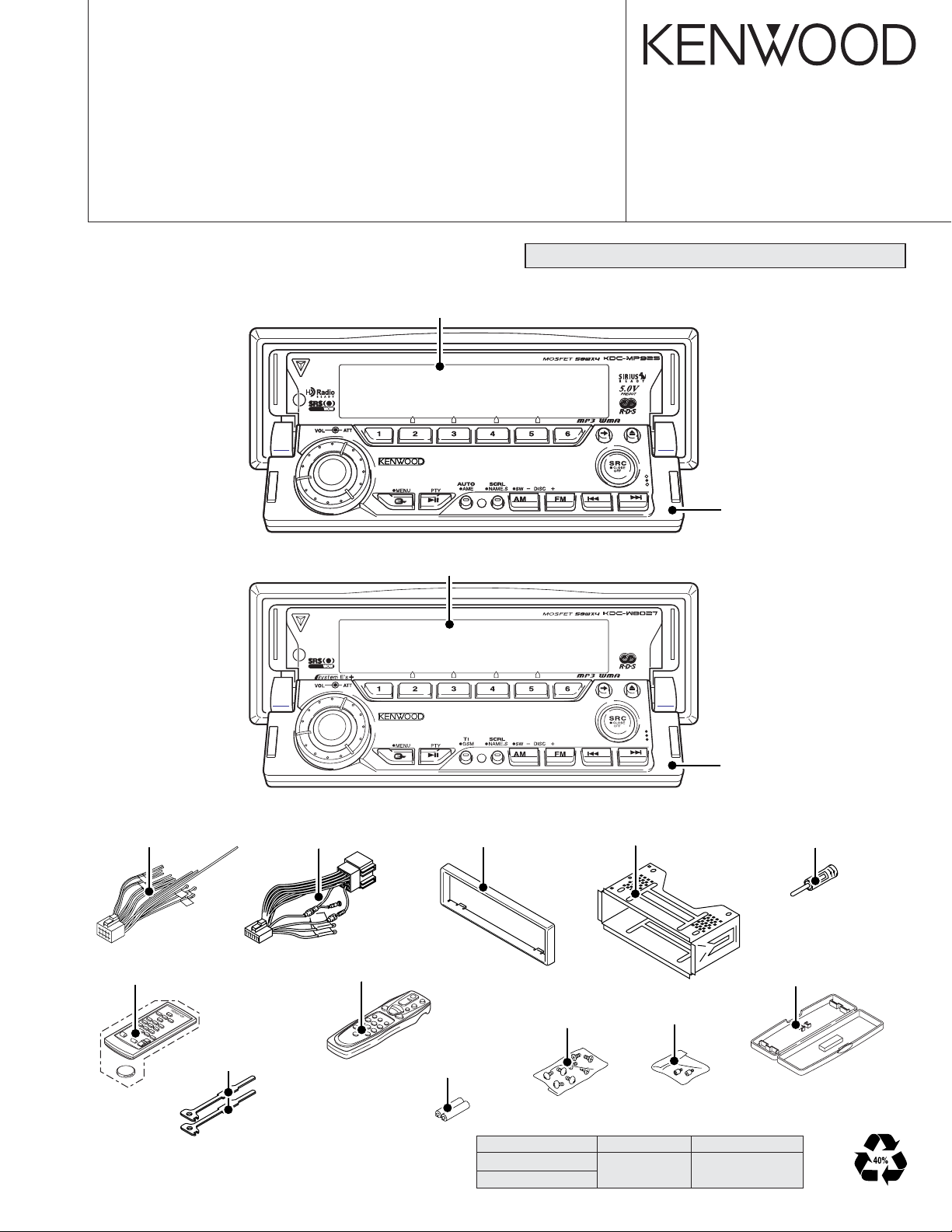
Panel assy
KDC-MP925 (A64-3226-01)
Panel assy
KDC-W8027 (A64-3232-01)
© 2004-02 PRINTED IN JAPAN
B53-0131-00 (N) 2439
CD mechanism extension cord (24PIN) : W05-0935-00
Panel assy
(A64-3248-02)
* DC cord
(E30-6295-05)
*Remote controller assy
(A70-2026-05) : RC-420
Lever
(D10-4674-04) x 2
* Depends on model. Refer to the parts list.
* DC cord
(E30-4942-05)
*Remote controller assy
(A70-2040-05) : RC-505
Escutcheon
(B07-3078-01)
*Size AA Battery
(Not Supplied)
TDF PANEL INFORMATION
MODEL PARTS NO. PANEL NAME
KDC-MP925
KDC-W8027
Mounting hardware assy
(J21-9823-03)
*Screw set
(N99-1723-05)
Y33-1790-61 TDF-M7000
Panel assy
(A64-3252-02)
* Antenna adaptor
(T90-0552-05)
Plastic cabinet assy
(A02-2731-13)
Screw
(N99-1734-05)
Page 2
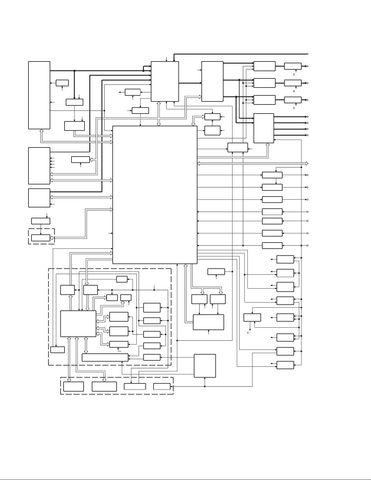
KDC-MP925/W8027
BLOCK DIAGRAM
(X34- )
TUNER
AUDIO OUT
S-METER
CD
CH
BU5V
Q501
EEP5V
IC1
EEPROM
TDF UNIT
(X16-208)
DISPLAY
UNIT
(X16-253)
SWITCH UNIT
(X16-256)
Q303,304
AM+B
8V
BU5V
8V
SERVO
CD4.7V
BACK UP
IC9
REMO
8V 8V
BUFFER
IC14
RDS
DECODER
EEPROM
SW5V
IC7
LEVEL
SHIFT
IC11
u-COM
ROT ARY
ENCODER
SW5V
LEVEL
SHIFT
IC8
BU5V
IC2
IC4
IC10
FL
KEY
KEY MATRIX
BPF
SW5V
IC1
2.5V
MASK
ROM
FLASH
ROM
BPF
AGC
8V
BUFFER
LEDLED
ILL+
AGC
RESET SW
8V
IC2
FM
AM
CD
E-VOL
CH
&
MPX
QUAL
SYSTEM
MICROPROCESSOR
PANEL5
Q6,10
PANEL
SW5V
IC6
3.3V
Q5
SW3.3V
Q4
FL3.3V
Q2,3
FL+B
KEY ILL
8V
IC15
MOTOR
FL+B
FAC
IC5
SYSTEM
E'S+
IC20
FOCUS
SW
IC8
SERVO
PANEL
MECHA
SW5V
DC/DC
WOW
RESET
BU5V
IC16
MOTOR
DRDR
IC6
IC9
8V
8V
MUTE
DRIVER
Q207,208
PRE MUTE
Q203,204
PRE MUTE
Q205,206
PRE MUTE
IC4
POWER
IC
BU5V
IC18
Q23,24
ANT-CON ANT CON
Q25
EXT AMP
Q26
DIMMER DIMMER
TEL MUTE
Q29
ACC DET
Q27
B.U DET
BU5V
SW5V
PANEL5V
SW14V
DC/DC A8V
9V
SERVO
CD4.7V
IC13
IC12
IC11
P-CON P CON
Q1,2
BU5V
Q3,601
SW 5V
Q502,503
PANEL
5V
Q4,5
SW 14V
Q6-8
A8V
Q9,602
SERVO
Q11-14
FL+B
IC19
SW REG
OP AMP
9V
OP AMP
9V
OP AMP
9V
AUX IN
PRE OUT
(SUB WOOFER)
PRE OUT
(REAR)
PRE OUT
(FRONT)
SP OUT (FL)
SP OUT (FR)
SP OUT (RL)
SP OUT (RR)
WIRED REMO/
OPEL DISP I/F
EXT.AMP.CON
TEL MUTE
ACC
BACK UP
2
Page 3
KDC-MP925/W8027
COMPONENTS DESCRIPTION
● SUB CIRCUIT UNIT (X16-2080-10)
Ref No. Application / Functions Operation / Condition / Compatibility
IC1 E2PROM E2PROM for security
● DISPLAY UNIT (X16-2530-11)
Ref No. Application / Functions Operation / Condition / Compatibility
IC1 Panel microprocessor Panel control microprocessor
IC2 ROM IC Graphic ROM
IC4 AVR For 3.3V power supply
IC5 AVR For 2.5V power supply
IC6 Buffer IC Level shift buffer IC (5V→3.3V)
IC7 Buffer IC Level shift buffer IC (3.3V→5V)
IC8 Remote control IC For Remote control sensor
IC9 Logic IC Control for FL contrast
IC10 Analog IC Spectrum analyzer IC
Q1 3.3V Regulator While PAN5V is applied when 3.3V regulator output is +3.3V
Q2 2.5V Regulator While PAN5V is applied when 2.5V regulator output is +2.5V
Q3,4 FL +B SW FL +B (VDD1) is turned on when Q3 base level goes H
Q5 3.3V SW SW3.3V is turned on when Q5 base level goes L
Q6,200 FL 3.3V SW FL +3.3V (VDD1) is turned on when Q200 base level goes H
Q7,8 Remote control ON SW The power supply of IC8, 10 is turned on when Q10 base level goes H
Q9 FL BLK SW VFD is turned on when Q9 base level goes H
Q11 Red LED SW Red LED is turned on when Q11 base level goes H
● SWITCH UNIT (X16-2560-10)
Ref No. Application / Functions Operation / Condition / Compatibility
Q1 DSI LED SW DSI LED blinks when Q1 base level goes H/L
Q2 KEY Illumination SW (Green) KEY Illumination SW “ON” when the Q2 base level goes H
Q3 KEY Illumination SW (Red) KEY Illumination SW “ON” when the Q3 base level goes H
Q4 KEY Illumination SW (Blue) KEY Illumination SW “ON” when the Q4 base level goes H
● CD PLAYER UNIT (X32-5540-00)
Ref No. Application / Functions Operation / Condition / Compatibility
IC1 Mechanism control microprocessor IC2 DSP CD signal processor, RF amp, Servo control
IC3 Decoder IC MP3/WMA decoder
IC4 BTL driver Focus, Tracking coil, Feed and Spindle motor driver IC
IC5 AVR SW3.3V AVR
IC6 AVR BU3.3V AVR
IC7 AVR BU2.5V AVR
IC8 Selector IC Serial audio data selector
3
Page 4
KDC-MP925/W8027
COMPONENTS DESCRIPTION
Ref No. Application / Functions Operation / Condition / Compatibility
IC9 AVR 3.3V AVR (IC2 DAC part)
Q1,4 Level shift FET Level shift (3.3V - 5.0V)
Q3,5 Level shift TR Level shift (3.3V - 5.0V)
Q6 Level shift TR Level shift (3.3V - 5.0V)
Q7 Level shift TR Level shift (3.3V - 5.0V)
Q8 APC Auto power control
Q9,10 Switching TR Sub beam delay control switch
● ELECTRIC UNIT (X34-3030-10, X34-3032-71)
Ref No. Application / Functions Operation / Condition / Compatibility
IC1 System control IC System control microprocessor
IC2 E-VOL & tuner IC E-VOL. FM/AM tuner & stereo decoder
IC3 Power supply IC For A8V AVR
IC4 Audio power IC Audio power amplifier
IC5 System IC For System E’s control
IC6 Audio control IC For WOW/FOCUS control
IC7 Power supply IC -9V AVR (For 4.5V Pre-out)
IC8 Reset IC When BU5V line voltage is less than 3.5V, this IC output line is “L”
IC9 Muting logic IC Control for MUTE, P-ANT & RESET muting
IC10 Buffer IC For spectrum analyzer
IC11~13 OP AMP For 4.5V Pre-out
IC14 RDS decoder Decode for RDS signal
IC15,16 Motor driver Control for Panel mechanism motor
IC18 P-CON IC Power control IC
IC19 Power supply IC Switching regulator IC for CD4.7V
IC20 Analog SW Control for WOW/FOCUS IC (IC4)
Q1,2 BU 5V AVR While BU is applied when BU5V regulator output is +5V
Q3,601 SW5V AVR When Q601base level goes H, SW5V regulator output is +5V
Q4,5 SW14V AVR When Q5 base level goes H, SW14V regulator output is +14V
Q6~8 Audio 8V AVR When Q6 base level goes H, A8V regulator output is +8.3V
Q9,602 Servo +B AVR When Q602 base level goes H, S+B regulator output is +7.5V
Q11~14 Illumination & DC/DC +B AVR When Q11 base level goes H, AVR output is +9.2V
Q15,16 Audio 10.5V AVR When Q16 base level goes H, AVR output is +10.5V
Q17~19 Pre Amp & -9V AVR
Q20~22 Pre Amp & +9V AVR
Q23,24 P-ANT SW When Q23 base level goes H, P-ANT SW output is +14V
Q25 Buffer EX amp control buffer
Q26 Small lamp det. SW When Q26 base level goes H, Q26 turned ON
Q18,19 work as differential amplifier, Q17 wark as driver and -9.1V is supplied to
OP AMP for Pre-out
Q20,22 work as differential amplifier, Q21 wark as driver and +9.4V is supplied to
OP AMP for Pre-out
4
Page 5
KDC-MP925/W8027
COMPONENTS DESCRIPTION
Ref No. Application / Functions Operation / Condition / Compatibility
Q27 BU detector When Q27 base level goes H, Q27 turned ON
Q29 ACC detector When Q29 base level goes H, Q29 turned ON
Q30,31 Muting driver When base level goes L, muting driver is turned ON
Q201 Buffer Noise detect buffer amp
Q202 E-VOL muting SW When Q202 base level goes H, muting SW is turned ON
Q203~208
Q210 AGC For AGC for spectrum analyzer
Q303,304 AM +B SW When Q303 base level goes H, AM +B is out to tuner unit
Q305 Buffer Composite signal buffer for RDS
Q501 E2P 5V SW When Q501 base level goes L, E2P 5V is out for E2PROM
Q502,503 Panel 5V SW When Q503 base level goes H, Panel 5V is out
Q603 SW When Q603 base level goes H, Q603 is turned ON
Pre-out muting SW When base level goes H, Pre-output is muted
MICROCOMPUTER’S TERMINAL DESCRIPTION
● SYSTEM MICROPROCESSOR : UPD703030GC041 (X34-303 : IC1)
Pin No. Pin Name I/O Description / Processing Operation
1 PLL DATA I/O Data input/output terminal for Tuner front-end
2 AM+B I/O AM+B (AM operation : H)
3 (FM+B) O FM+B (FM operation : H, Last FM : H with RDS, RBDS model)
4PAN E2P DATA I/O Variable illumination D/A converter, E2PROM DATA terminal
5PAN E2P CLK I/O Variable illumination D/A converter, E2PROM CLK terminal
6 EVDD - VDD 5V
7 EVSS - GND
8 AFS O Time constant switching for noise detection (FM seek, AF search, AUTO 0 : L, Receiving : H)
9 BEEP O BEEP audio output terminal
10 REMO I Remote control input terminal
11 P MUTE O Audio power IC muting control terminal (POWER OFF, ALL OFF, TEL MUTE : L)
12 SVR O Audio power IC SVR discharge circuit control terminal
13 IC2 SDA I/O CD mechanism, IC2, IC5, ROM correction DATA line
14 IC2 CLK I/O CD mechanism, IC2, IC5, ROM correction CLOCK line
15 P STBY O Audio power IC Stand-by terminal (POWER IC ON, ALL OFF : H, POWER IC OFF : L)
16 P CON I/O Power control terminal (POWER ON : H, POWER OFF, ALL OFF : Hi-Z)
17 WOW MODE2 O WOW control terminal 1
Fig.
5
Page 6

KDC-MP925/W8027
MICROCOMPUTER’S TERMINAL DESCRIPTION
Pin No. Pin Name I/O Description / Processing Operation
18 TEST - NC (GND)
19 DIAG I Over voltage/Over current detection terminal (Normal : H, Bad condition : L)
20 MUTE O MUTE output terminal (ON : OPEN, OFF : L)
21 PRE MUTER O PREOUT (Rch) muting control terminal
22 PRE MUTEL O PREOUT (Lch) muting control terminal
23 BU DET I
24 ACC DET I ACC detection terminal (With ACC : L, Without ACC : H)
25 FOCUS I/O WOW/FOCUS control terminal (FOCUS HI : H, FOCUS LOW : L)
26 EXT AMP CONT O External amplifier control terminal
27 DIMMER I Small lamp detection terminal (ON : L, OFF : H)
28
29 P ON I/O SW14V, SW5V control terminal (POWER ON : H, POWER OFF : Hi-Z)
30 ILL ON I/O FL, illumination control terminal (ON : H, OFF : Hi-Z)
31 RESET I Reset input terminal
32,33 XT1/XT2 - Sub clock (32.768KHz)
34 REGC - Connect to 1µF capacitor
35,36 X2/X1 - Main clock (20MHz)
37 VSS - GND
38 VDD - AVR 5V
39 CLKOUT - NC
40 LX REQ M O Communication request to external slave unit (Request : L)
41 LX MUTE I Mute request from external slave unit (MUTE : H)
42 LX CON O External slave unit (ON : H, OFF : L)
43 LX RST O Reset output to external slave unit (Normal : L, After system reset : H 400ms or more and then L)
44 CD MECHA+B O CD4.7V output terminal (CD : H, Except CD source : L)
45,46 TYPE0/TYPE1 I Destination select terminal
47,48
49 PAN5V O Panel 5V control terminal (ON : H, Momentary power dropped : Hi-Z)
50 E2P5V I/O E2PROM, D/A converter power supply control terminal (ON : L, OFF : Hi-Z)
51 DSI I/O DSI control (ON : L, OFF : Hi-Z)
52 MC REQ O Communication request to panel microprocessor
53 PAN RST O Reset output to panel microprocessor (Normal : H, Reset, Momentary power dropped : L)
54 WOW MODE3 O WOW control terminal 1
55 DVDD - AVR 5V
56 DVSS - GND
57 SC CON O Panel microprocessor control terminal (POWER OFF, ACC OFF : L)
58 M RST O Reset output to CD mechanism (Normal : H, Reset : L)
59 M STOP O Stop request to CD mechanism (STOP : L, CD : H)
60 CD SW3 I CD DOWN SW detection terminal (CD disc chucking : H)
61 LO/EJ I/O CD mechanism loading/ eject selector (STOP, Brake : Hi-Z, LOADING : L, EJECT : H)
ANT CONT(TYPE2)
IC2 TYPE0/TYPE1
Momentary power dropped detection terminal (No Backup, Momentary power dropped : H, Backup : L)
I/O Antenna control/Destination select terminal (TUNER ON : H)
.
I IC2 destination select terminal
Fig
6
Page 7

KDC-MP925/W8027
MICROCOMPUTER’S TERMINAL DESCRIPTION
Pin No. Pin Name I/O Description / Processing Operation
62 MOSW O CD mechanism motor driver SW (LOADING, EJECT, Brake : H)
63 FPM MOTOR B O FPM mechanism (Slider) control terminal 2
64 FPM MOTOR F O FPM mechanism (Slider) control terminal 2
65 FPM MOTOR O O FPM mechanism (Angle) control terminal 2
66 FPM MOTOR C O FPM mechanism (Angle) control terminal 2
67 O DATA I/O External display DATA terminal 2
68 O CLK I/O External display CLK terminal
69 O CE I/O External display chip enable terminal
70 M MUTER I Mute request from CD mechanism (Rch ON : L)
71 AVDD - AVR 5V
72 AVSS - GND
73 AVREF I Connect to P-ON (29PIN)
74 M MUTEL I Mute request from CD mechanism (Lch ON : L)
75 PAN DET I PANEL, E2PROM detection terminal (With panel : L, Without : H)
76 PHONE I PHONE detection terminal (TEL MUTE : 1V or less, NAVI MUTE : 2.5V or more)
77 FPM SW4 I
78 FPM SW1 I FPM mechanism position detect terminal 2
79 FPM SW2 I FPM mechanism position detect terminal 2
80 FPM SW3 I FPM mechanism position detect terminal 2
81 FPM PHOUT I FPM mechanism position detect terminal (2.2V or more : H) 2
82 S METER I S meter detection terminal
83 NOISE I FM noise detection terminal
84 IFC OUT I Front end IFC OUT input terminal (Receiving station : 2.5V or more)
85 POWER DET I Audio power IC DC offset detection
86 CD SW4 I 8cmDISC detection terminal (8cmDISC : L)
87 R CLK I RDS decoder clock input terminal
88 LX REQ S I Receive request from external slave unit (Request : L)
89 SC REQ I Communication request from panel microprocessor
90 CD SW1 I LOADING SW detection terminal (LOADING start, POWER OFF : L)
91 CD SW2 I 12cmDISC detection terminal (12cmDISC, POWER OFF : L)
92 R QUAL I RDS decoder QUAL input terminal
93 R DATA I RDS decoder DATA input terminal
94 LX DATA S I Data input from external slave unit
95 LX DATA M O Data output to external slave unit
96 LX CLK I/O Clock input/ output with external slave unit
97 PAN RX I Data input from panel microprocessor
98 PAN TX O Data output to panel microprocessor
99 WOW MODE1 O WOW control terminal
100 PLL CLK I/O Clock input/ output to Tuner front-end 1
FPM mechanism position detect/ CD Mechanism detection terminal
(3.75V or more : No mechanism, 1.25V or more : H, Less than 1.25V : L)
Fig
2
7
Page 8
KDC-MP925/W8027
MICROCOMPUTER’S TERMINAL DESCRIPTION
Fig.1 WOW mode operation
MODE WOW MODE1 WOW MODE2 WOW MODE3 FOCUS
BYPASS L L L Don’t care
TuBass L H L Don’t care
3D-STEREO L L H Don’t care
FOCUS LOW H L L L (Hi-Z)
FOCUS HI H L L H
WOW LOW H H H L (Hi-Z)
WOW HI H HHH
Fig.2 FPM motor control
SLIDE FPM mechanism
FPM MOTOR B FPM MOTOR F operation
LLStandby
HLBackward operation
LHForward operation
HHBrake
ANGLE FPM mechanism
FPM MOTOR O FPM MOTOR C operation
LLStandby
HLAngle open direction
LHAngle close direction
HHBrake
● PANEL MICROPROCESSOR : 703132GJ011-A (X16-253 : IC1)
Pin No. Pin Name I/O Description / Processing Operation
1~7 D14~D8 I/O External ROM data input/output terminal
8 3.3VDD - AVR 3.3V
9 VSS - GND
10~17 D7~D0 I/O External ROM data input/output terminal
18 FL GCP1 O FL bright control terminal
19 SC REQ O Communication request to system microprocessor (H : Request)
20 MC REQ I Request from system microprocessor (H : Request)
21 SC CON I Panel microprocessor control (H : While operation)
22 FL BLK O Display control SW for FL driver (H : Display ON, L : Display OFF)
23 2.5V VDD - AVR 2.5V
24 VSS - GND
25~27 KS5~KS3 O Key scan output terminal
28,29 TDI/TDO - NC
30,31 KS2,1 O Key scan output terminal
32 TRST I NC
33 ROTARY CCW I Volume input terminal
34 ROTARY CW I Volume input terminal
35,36 TMS/TCM O NC
37 3.3VDD - AVR (3.3V)
8
Page 9

KDC-MP925/W8027
MICROCOMPUTER’S TERMINAL DESCRIPTION
Pin No. Pin Name I/O Description / Processing Operation
38 VSS - GND
39~42 KI1~KI4 I Key return input terminal
43 FLGCP2 O FL bright control terminal
44 NC - NC
45 SYS TX I DATA input from system microprocessor
46 SYS RX O DATA output to system microprocessor
47 FL CLK3 O Clock output to FL driver
48 KI5 I Key return input terminal (SRC, OPEN, EJECT interrupt port)
49 FL DATA3 O DATA output to FL driver
50 SCK1 I Clock input from FL driver
51 NC - NC
52 FL DATA2 O DATA output to FL driver
53 CLK IN1 I Clock input from FL driver
54 NC - NC
55 FL DATA1 O DATA output to FL driver
56 3.3VDD - AVR (3.3V)
57,58 X2/X1 - Main clock (5MHz)
59~61
62 2.5V VDD - AVR 2.5V
63 VSS - GND
64,65 MODE0,1 - GND
66 PAN RST I Reset signal request form system microprocessor (L : Reset)
67 VREF - Connect to 83PIN (VREF)
68,69 NC - NC
70,71 AVSS1,0 - GND
72 VREF - Connect to 83PIN (VREF)
73 WAVE IN I Audio signal input terminal
74 F06 I Spectrum analyzer input terminal (BPF 10KHz)
75 F05 I Spectrum analyzer input terminal (BPF 3.3KHz)
76 F04 I Spectrum analyzer input terminal (BPF 1KHz)
77 F03 I Spectrum analyzer input terminal (BPF 330Hz)
78 F02 I Spectrum analyzer input terminal (BPF 150Hz)
79 F01 I Spectrum analyzer input terminal (BPF 63Hz)
80 NC - NC
81 2.5V VDD - AVR 2.5V
82 VSS - GND
83 VREF CON O VREF control terminal (Connect to VREF terminal)
84 NC - NC
85 FLGCP3 O FL bright control terminal
86 NC - NC
CVSS/CKSEL/PSEL
- GND
9
Page 10

KDC-MP925/W8027
MICROCOMPUTER’S TERMINAL DESCRIPTION
Pin No. Pin Name I/O Description / Processing Operation
87 FL LATCH O Latch output to FL driver IC
88,89 NC - NC
90 REMO ON O Power supply control for remote control IC (H : ON, Hi-Z : OFF)
91 FL3.3V SW O FL3.3V control terminal (H : ON, Hi-Z : OFF)
92 FL+B SW O FL+B control terminal (H : ON, Hi-Z : OFF)
93 3.3V SW O 3.3V control terminal (L : ON, Hi-Z : OFF)
94 NC - NC
95 OE O OE control for Flash ROM (L : DATA transmission, Hi-Z : Wait ready)
96 NC - NC
97 WE/WR O WRITE/READ control for Flash ROM (L : Writing, Hi-Z : Wait ready)
98 3.3V VDD - AVR 3.3V
99 EVSS - GND
100 CE ROM O CE control for ROM (L : DATA transmission, Hi-Z : Wait ready)
101 CE F/ROM O CE control for Flash ROM (L : DATA transmission, Hi-Z : Wait ready)
102
103,104 NC - NC
105 GREEN LED O Select for illumination (GREEN H : ON, L : OFF)
106 RED LED O Select for illumination (RED H : ON, L : OFF)
107 DISP LED O DISP LED control (Normal H: ON, L : OFF)
108 BLACK DISP O Light up to DISP LED (H : ON, L : OFF)
109,110 NC - NC
111 SA RST O Reset for spectrum analyzer (H : Reset, L : Normal)
112 3.3V VDD - AVR 3.3V
113 EVSS - GND
114~117
118~123
124 2.5V VDD - AVR 2.5V
125 VSS - GND
126~133
134 3.3V VDD - AVR 3.3V
135 EVSS - GND
136~143
144 D15 I/O External ROM data input/output terminal
FLASHROM CHECK
NC - NC
A21~A16 O Address bus
A15~A8 O Address bus
A7~A0 O Address bus
OWriting condition check for Flash ROM (H : OK, L : NG)
10
Page 11

TEST MODE
KDC-MP925/W8027
● How to enter the test mode
While pressing and holding the Preset 1 and Preset 3 keys,
reset the unit.
● How to exit from the test mode
While holding the Preset 6 key, reset the unit.
Note : Turning ACC off, po wer off, momentary power down
or panel detaching does not terminate the test mode.
● Initial status in the test mode
• Sources : ALL OFF
• Display : All segments are lit.
•Volume : -10dB (displayed as “30”)
• Loudness : OFF
• CRSC : OFF regardless of the presence of switching function.
• SYSTEM Q : Flat
•WOW : All OFF
• BEEP : When pressing any keys, the buzzer generates a
beep at any time.
•AUX : ON
• MENU SYSTEM Q : OFF
•Variable model : Default is white
• Multifunction : Source dependency (Preset, SCAN, etc.)
● Special display in Tuner mode
When any of the following messages is displayed in Tuner
mode, the F/E may be abnormal.
• “TNE2P NG” : The EEPROM is set to the default (unstable
values) because the F/E was shipped without passing
through the adjustment process, etc.
• “TNCON NG” : Comm unication with the F/E is not possible.
● Forced switching of K3I
Each press of the Preset 6 key in Tuner mode should switch
K3I from AUTO→Forced Wide→Forced Middle→Forced
Narrow→AUTO.
The initial status is AUTO and the display shows these
modes as follows.
•AUTO : FMA
•Forced Wide : FMW
•Forced Middle : FMM
•Forced Narrow : FMN
● Test mode specifications of the CD receiver
•Forced ejection is inhibited in the reset start operation. When
the unit is reset while a CD is loaded in it, resetting does
not recognize the CD.
• Each press of the Track Up key jumps to the following track
numbers :
No. 9→No. 15→No. 10→No. 11→No. 12→No. 13→No. 22
→No. 14→No. 9 (The cycle restarts from here.)
• Each press of the Track Down key jumps to the previous
track number to the track being played.
•When the number of total trucks of the MP3 disc or the
WMA disc is less than 9, 1st truck is played.
• When the disc media is CD, A short press of the Preset 1
key jumps to the track number 28.
• When the model is equipped the CD mechanism assembly
adapted for MP3 or MP3/WMA disc, the mechanism name
and version number are displayed during the FL model is
lower stand and Display mode of LCD model is DNPS.
● Audio-related specifications
• Pressing the ✽ key on the remote initiates the audio adjustment mode.
• BL/F key on the Fader initials.
• Continuous holding of a remote control key is inhibited, and
workings are short press of any keys.
• Bass, Middle and Treble are adjusted in 3 steps of -8 / 0 /+8
with the Track Up/Down keys (Default value at 0).
• Balance is adjusted in 3 steps of L15 / 0 / R15 with the
Track Up/Down keys (Default value at 0).
•Fader is adjusted in 3 steps of R15 / 0 / F15 with the Track
Up/Down keys (Default value at 0).
• HPF is adjusted in 2 steps of OFF / 170Hz (or 200Hz) with
the Track Up/Down keys (Default value at OFF).
• LPF is adjusted in 2 steps of OFF / 120Hz with the Track
Up/Down keys (Default value at OFF).
• Bass f, Bass Q, Bass EXT, Middle f, Middle Q and Treble f
are not dealt with by the audio adjust.
•The WOW key passes during the audio adjustment as following steps (WOW model only).
Ordered TruBass FOCUS SRS Display
1 OFF OFF OFF SRS WOW OFF
2ONOFF OFF SRS TruBass ON
3 OFF LOW OFF FOCUS LOW
4 OFF HIGH OFF FOCUS HIGH
5 OFF OFF ON SRS ON
6ONHIGH ON SRS WOW HIGH
11
Page 12

KDC-MP925/W8027
TEST MODE
● Menu-related specifications
• A short press of the Q key initiates the menu mode.
• Pressing the DNPP key on the remote initiates the Menu
mode.
• Continuous holding of a remote control key is inhibited, and
workings are short press of any keys.
• Contrast is adjusted in 3 steps of 0 / 5 / 10 with the Track
Up/Down keys (Default value at 5).
● Backup current measurement
When the unit is reset while ACC is OFF (i.e. by turning
Backup ON), the MUTE terminal goes OFF in 2 seconds in
place of 15 second. (The CD mechanism is not activated at
this time.)
● Special display when the display is all on
Pressing the Preset keys while the power is ALL OFF displays the following information.
[PRESET 1]
[PRESET 2]
[PRESET 3]
[PRESET 4]
[PRESET 5]
[PRESET 6]
FM key Display ROM collection version.
Version display (8 digits, Month/Day/Hour/Minute)
(Display) SYS xxxxxxxx :
PAN xxxxxxxx : FL model only
MEM
xxxxxxxx :
Serial number display (8 digits)
(Display) SNo xxxxxxxx
Short press : View power ON time. (The All OFF
period is not counted.)
2 seconds long press/hold : Clear power ON time
at the power ON time displaying.
(Display) PonTim xxxxx Max. 60000 (hours)
Short press : Display CD operation time.
2 seconds long press/hold : Clear CD operation
time at the CD operation time displaying.
(Display) CDTim xxxxx Max. 60000 (hours)
Short press : Display CD ejection count.
2 seconds long press/hold : Clear CD ejection
count at the CD ejection count displaying.
(Display) EjeCnt xxxxx Max. 60000 (times)
Short press : Display Panel open/close count.
2 seconds long press/hold : Clear Panel open/close
count at the Panel open/close count.
(Display) PnCnt xxxxxx Max. 600000 (times)
(Display) ROM R xxx Invalid : “R – – –”
4 contrasts FL model only
AM key Display panel E2PROM condition.
(Display) P–ROM OK (Registered code)
P–ROM NG (Code is write in error)
P–ROM WAIT (Unregistered code)
P-ROM NON
(Panel security nonfunctional)
● Panel mechanism
• Auto-panel close inhibition when set-in the CD.
• The panel operation inhibition at power ON/OFF and ACC
ON/OFF.
• The panel position changing Eject→Last with a short press
of the PLAY/PAUSE keys.
● Other specifications
• No displays such as “CODE OFF/ON” during Power-ON.
• The LINE MUTE inhibition time is one second from 10 seconds when start-up the test mode.
• Do not write the security code with the security jig on the
test mode.
•Do not wr ite the serial with the serial writing jig on the test
mode.
• OEM display output is not stop if OEM displa y not connection on the test mode.
● Switching the frequency span (K/M type)
While holding the Preset 1 key and Preset 5 key, reset the
unit.
● Demonstration mode
1. How to enter to the Demonstration mode
1. Hold down the [Q] key and [TI (AME)] k ey button when the
power is on and press the Reset button.
2. This will enter to the Demonstration mode.
2. How to chancel the Demonstration mode
1. Hold-down the Preset [5] key button when the power is on
and press the Reset button.
2. This will cancel the Demonstration mode.
12
Page 13

TEST MODE
KDC-MP925/W8027
● Security information
1. Forced Power ON mode (All models)
Even when the security (Cord) is approved, resetting the
unit while holding the Q and Preset 4 keys makes it possible to turn the power ON for 30 minutes.
After 30 minutes have elapsed, it is not possib le to return to
the previous condition unless the unit is reset again. (Security code is doing not clear at this mode. Put the power on
fill-in.)
When panel security was set up for the unit when it is can
not power on.
In this case, you can use new ROM for the TDF panel that
the unit can be power on for test mode.
Note : Don’t enter the panel security set up for new ROM
panel. User can not power on the unit.
2. Method of registration of the security code after
EEPROM (F/E) replacement (Code security model)
1. Enter the test mode. (See How to enter the test mode)
2. Press the MENU key to enter the Menu mode.
3. When the message “Security” is displayed, press and hold
the Track Up/Down key for 1 second to enter the security
registration mode.
4. Enter the code using the FM/AM/Track Up/Track Down keys.
FM key : Number up
AM key : Number down
Track Up key : Cursor right shift
Track Down key : Cursor left shift
5. Hold down the Track Up key for at least 3 seconds and the
message, “RE-ENTER” appears, so once again enter the
code according to Step 4 above.
6. Press and hold the Track Up key for 3 seconds until “APPROVED” is displayed.
7. Exit from the test mode. (See 2. How to exit from the test
mode)
Note 1 : All Clear is not applicable to the security code of
this model.
Note 2 : When the F/E changed, need re-inscription because the panel security is clear.
3. How to inscription the panel security code
1. Enter the test mode.
2. Pressing the AM key on all lighting, check the “P-ROM W AIT”
display.
3. The NEXT key is long press 2 seconds, writing the code.
4. Display is “P-ROM OK”.
5. Exit from the test mode.
Note : E2PROM connection is NG when displa y is “P-R OM
NG”, so detach the panel and rewrite after the display is
“PROM WAIT”. This code can not clear.
4. Simple way to c lear the security code (K type only)
1. During code request mode, press the Track UP key for at
least 3 seconds while holding down the AUTO key. (– – – –
will disappear)
2. Enter, “KCAR” with the remote controller as described below.
• Press the remote controller 5 key twice, and press the Track
Up key. (Enters a “K” )
• Press the remote controller 2 key three times, and press
the Track Up key. (Enters a “C” )
• Press the remote controller 2 key once, and press the Track
Up key. (Enters an “A” )
• Press the remote controller 7 key twice, and press the Track
Up key. (Enters an “R” )
3. Security function is canceled and unit sets to All-Off mode.
4. Code request mode appears if a mistake was made in entering the numbers.
13
Page 14

A B C D E
7
KDC-MP925/W8027
1
PC BOARD (COMPONENT SIDE VIEW)
ELECTRIC UNIT X34-3030-10, X34-3032-71 (J74-1473-32)
CN1
12
CN2
11
2
1
R262
2
Q13
Q8
3
Q1
Q9
R264
R48
R46
R47
EBEBEBEB
EB
Q11
EB
Q12
C204
R14
R6
EB
Q7
IGO
IC3
EB
C3
C5
R7
4
5
R263
C205
Q6
D7
C203
C9
C700
2
1
224
1
C277
C272
MUTE
1222
1123
1
D504
R508
R503
R504
R145
R146
C36
L1
EB
EBEBEBEBEB
R220
R233
X2
C101
R106
R526
Q208
Q207
Q203
Q204
Q206
Q205
C264
R184
R183
X1
C298
C269
R101
R108
R109
R525
CN4
C100
C241
IC20
5
8
C240
R609
D1
C265
4
1
26
R102
50
R119
C297
1
C268
14
24
25
R608
36
37 48
C226
TEST
R180
R121
R120
IC6
C223
IC5
C222
R179
IC1
13
C227
R172
R123
R122
C238
12
1
R170
R171
28
15
R217
R205
R625
C228
R169
125
7551
R127
C234
C229
R167
100
76
R129
C259
R219
R623
C48
R131
C233
R218
R624
R626
R136
R135
C201
C215
IC2
33
34 44
C219
C218
C202
CLK DATA
R164
R163
R162
R160
R159
L102
R153
R152
R186
R148
R144
R143
R142
R141
R134
R133
4
C299
C300
C267
C266
C270
16
1
J1
R42
85
1
85
IC13
IC11
C47
D15
R244
4
R245
R221
41
R232
58
9
8
Q24
C8
R33
C6
R34
Q25
W3
C41
BE
R29
R49
5
IC18
81
D17
D16
R32
Q26
EB
IC12
C43
R35
C42
C31
1
C271
Q15
EB
456
4
C30
D8
R107
5V
RST
C250
C274
IC4
25
C273
C275
C2
CN3
16
15
124
321
A2
C18
L2
C12
1
CN5
28
CN6
15
1
6
C16
L3
C23
C10
P1
7
14
Page 15

JIHGF
KDC-MP925/W8027
1
24
25
C279
C275
C278
C206
N3
2
1
X34-303x-xx
Ref. No. Address
IC1 5D
IC2 3D
IC3 3A
IC4 2E
IC5 3D
IC6 4D
IC11 3C
IC12 4C
IC13 3C
IC18 3B
IC20 4C
Q1 3A
Q6 3A
Q7 3A
Q8 3A
R261
L7
12
C314
R308
R307
C311
R306
C502
X3
Ref. No. Address
Q11 2A
Q12 3A
Q13 2A
Q15 4C
Q24 2B
Q25 3B
Q26 4B
Q203 3C
Q204 4C
Q205 4C
Q206 4C
Q207 3C
Q208 3C
Q305 4F
CN7
L305
L307
Q305
EB
R305
L306
Q9 3A
DISPLAY UNIT
X16-2530-11 (J74-1587-02)
W2
A1
1
24
ED1
D13
D14
IC8
3
1
4
2
SWITCH UNIT
X16-2560-10 (J74-1590-02)
D1
S15
D2
S12
C10
D20
S17
C9
D19
S16
C8
D18
S18
C7
D17
S13
C5
D15
S8
12 3 4 5 6 SHIFT
S3
D14
C4
13 4201817
R13
R15
Q1
SRC
Q2
D13
D12
EB
Q3
EB
R17
EB
D21
Q4
D25
D22
EB
S10
R16
R14
R12
S9
S14
D4 D3
D5
S4
S19
D6
D7
S6S7
SCRLAUTO
S20
D8
D9
S2 S11
D10
S1
S21
D11
VOLUME
AM FM
RESET
MENU
2
3
4
5
6
Refer to the schematic diagram for the
values of resistors and capacitors.
X16-2530-11
Ref. No. Address
IC8 6H
X16-2560-10
Ref. No. Address
Q1 4I
Q2 5I
Ref. No. Address
Q3 5I
Q4 4J
7
15
Page 16

K L M N O
D10
3
C
R28
KDC-MP925/W8027
1
PC BOARD (FOIL SIDE VIEW)
ELECTRIC UNIT X34-3030-10, X34-3032-71 (J74-1473-32)
D214
D213
D215
D216
2
D208
R260
R304
FPM1-
18
R257
D501
R509
X34-303x-xx
R259
R256
D206
C208
R268
D502
R511
R512
R510
R266
C290
R267
C310
C309
Ref. No. Address
IC7 5O
IC8 5O
IC9 4N
IC10 5P
IC14 4L
IC15 6M
IC16 5M
IC19 6O
Q2 3Q
Q3 4P
Q4 3Q
Q5 3Q
Q14 3Q
Q16 4O
Q17 5O
Q18 5O
Q19 5O
Q20 6O
D301
GND
3
PLL+B
4
5
SUB CIRCUIT UNIT
X16-2080-10 (J74-1476-02)
14 2
6
15
1
4
X16-2080-10
Ref. No. Address
IC1 6K
7
D207
FM+B
AM+B
C303
Q304
L303
EB
L304
C304
C505
C305
C307
C501
BE
R303
FPM1+
C312
VDD
C313
IC14
916
IF1+B
J1
1
8
CP1
IC1
5
Q303
D205
C207
R502
D503
R269
R501
Ref. No. Address
Q21 5O
Q22 5O
Q23 2O
Q27 3P
Q29 3P
Q30 4N
Q31 4N
Q201 3M
Q202 3M
Q210 5P
Q303 3L
Q304 3L
Q501 5O
Q502 6N
Q503 6O
Q601 3P
Q602 4Q
Q603 4N
58
IC17
14
R506
R507
D211
D209
D210
TH1
C276
C209
C211
R505
R201
R202
R204
C210
C212
D212
C214
Q202
BE
EB
C213
R203
Q201
C199
C221
R279
D201
D202
14 8
IC9
17
R161
R158
RQUAL
R156
R155
R154
R151
C109
C319
C318
R140
R139
610
R138
R137
IC16
15
R616
R615
1
51
IC15
C316
R516
106
C317
FPM2
FPM2+
L201
C220
R618
R617
R515
E2P5V
C231
R206
C230
R210
R209
R208
D508
D506
C255
R280
C232
R150
R149
SERV GND
SERV +B
C257
C253
C251
Q30
R165
C603
R130
SW4.7V
DGND
R519
R518
R517
D507
C237
C235
R166
C110
R128
E GND
C224
C225
R207
D20
R132
BU5
C217
C216
C236
C239
R173
R126
D601
C260
C261
C262
C263
C258
C256
C254
C252
Q31
R174
R125
R620
R601
EBEB
R175
R176
R124
C2
R607
R610
R603
R604
R606
R605
R177
R178
R185
R103
R521
A GND
D505
R602
D21
R181
C107
R522
R520
D509
R611
R612
Q603
R182
C104
R111
R112
R524
R523
CLK
Q502
BE
PAN5V
FL GND
EB
C111
R118
R527
FAC1
C602
C601
R614
R613
C102
R117
DATA
FAC2
C103
R113
R114
R115
R701
R621
R116
D101
R514
R513
C106
EB
BE
FL+B
C13
R12
R248
R249
R225
R224
R236
R237
R17
D9
R110
IC8
DGND
Q501
C504
Q503
BU
R246
R247
R223
R222
R234
R235
Q16
R18
BE
L101
Q21Q22
12
43
SW4.7
R11
R10
IC19
58
R250
R251
R227
R226
R238
R239
R24
C503
L4
+9V
C39
EB
EB
R21
GND
R252
R253
R229
R228
R240
R241
C11
R20
R27
14
C40
Q23
EB
EB
R19
R22
BE
Q17
Q18
EB
C38
Q20
Refer to the schematic diagram for the values of resistors and capacitors.
R31
D13
D12
R254
R255
R231
R230
R242
R243
9V
58
IC7
14
R25
C
Q19
C37
R23
R26
EB
D5
C22
16
Page 17

TSRQP
D5
Q19
KDC-MP925/W8027
1
R31
D13
D12
R254
R255
R231
R230
R242
R243
C34
V
5
IC7
14
R25
C33
C37
R23
R26
E
20
C22
R28
D10
R41
C46
C35
C32
D217
C17
D11
R37
R38
C296
C15
NGND
NR
C284
R30
R43
R45
D18
R36
Q27
EB
R274
R271
R276
IC10
R278
14
1
C293
C292
EB
R277
NL
C289
C44
R16
C294
FGND
C285
C281
D19
C45
R44
A8V
R4
R3
R270
58
Q210
FL
C282
D204
Q29
Q601
Q3
C21
R272C291
C295
FR
RGND
C287
C280
BE
EB
BE
R273
SW5V
AUXL
RR
RL
AUXG
C283
C288
D203
D2
SERVO+B
R275
AUXR
R13
R265
C286
R15
D6
C14
BE
Q5
BE
EB
Q4
W1
R1
C4
D3
R2
C701
X16-2530-11
Ref. No. Address
IC1 3R
IC2 2R
IC4 6R
IC5 6R
IC6 5R
IC7 5R
IC9 3S
IC10 5R
Q1 6R
Q2 6R
Q3 6R
Q4 6R
Q5 5R
Q6 2R
Q7 6R
Q8 6S
Q9 2R
Q11 6R
Q200 2S
Q14
D4
ILL+B
C7
R8
BU5V
R9
Q602
CH+B
CH GND
R5
SW14V
EB
BE
DISPLAY UNIT
X16-2530-11 (J74-1587-02)
Q6
L8
1
4
CP13
109
72
R7
SYSRX
SYSTX
SCREQ
SCCON
MCREQ
PANRST
FLGND
C29
R36
C30
Q3
R300
R43
EB
R203
124
C27
CP9
108 73
C11
R6
C7
DSI
RST
ANA
REMO
CP3
D3
R35
R27
EB
Q7
EB
Q10
R204
C13
R12
R10
R50
R9
C12
E2P5V
CP31
C28
EB
R201
EB
R202
C200
120
IC9
58
CP200
CP300
CP10
R11
CP8
L3
E2PDATA
FAC1
FAC2
R3
D1
R34
C31
Q8
R26
R41
Q200
CP19
C15
IC2
CP21
CP22
CP12
IC3
CP24
CP23
CP11
R28
R49
C14
CP30
CP14
Q9
L9
25 48
R30
EB
R29
C35
C36
R25
21 40
C26
C25
C38
C39
C37
CP17
L10
CP20
CP18
CP15
144
C16
CP16
136
C17 R14
Q2
CP25
IC1
C18
CP26
C10
C9
R8
X1
TEST
E2PCLK
132
28
CN1
1
ILL+B
FL+B
PANDET
D4
R2
CP27
D2
C19
R23
R22
Q5
R21
EB
CP32
18 10
IC10
R40
R37
R39
19169
R38
CP1
EB
R19
IC4
45
R24
R20
R18
Q4
EB
R32
C23
R17
R42
R33
L1
CLK
R16
GREEN
RED
KI5
KI4
KI3
KI2
KI1
ESDGND
CP4
IC7
C34
C33
C32
R45
+2.5V
DI
CBC
Q11
C5
L2
R5
VOLB
CP5
14
85
R206
IC5
C4
37
L4
C8
CP7
DO
CN2
KS4
KS3
KS2
KS1
VOLA
R4
CP2
C22
81
R44
R47
R46
BEE
R48
+3 3V
Q2
EB
54
31
R200
L5
L6
L7
DGND
D5
CP28
C20
CP6
IC6
Q1
BE
C2
C1
C21
R1
13
R31
SWITCH UNIT
X16-2560-10 (J74-1590-02)
FROM CHECK
KI3
KI2
PAN5V
R5
C1
ESDGND
C12
R10
R1
R2
C11
DSI
D24
R11
R9
2
3
R8
RST
R3
R4
GREEN
KI4
KI5
RED
KS3
KI1
KS2
PAN5V
VOLB
VOLA
C3
DSI
KS4
124
CN1
ILLGND
DGND
ILL+B
R7R6
S5
KS1
C2
4
5
6
7
17
Page 18

U V W X Y
KDC-MP925/W8027
1
PC BOARD (COMPONENT SIDE VIEW)
CD PLAYER UNIT X32-5540-00 (J74-1552-12)
S2
C32
C66
CP11
C25
C67
R38
C50
C29
2
S1
R27
R66
C72
L1
CP6
3
R65
32 17
C44
R68
1633
IC3
C27
CP12
C69
R67
C18
C35
RFOK
C46
CP13
48
4
CP14
CP15
C13
R49
C15
C11
5
S4
6
X32-5540-00
R48
C41
MIACK
C10
R47
1
6449
C37
R46
/RESET
R42
Q4
G
D
S
MIDIO
CP5
R69
R13
CP7
Q7
EB
CP3
S3
IC6
C8
R12
C3
1345
R6
CBE
BEC
C52
Q5
CP2
R50
R63
Ref. No. Address
IC3 4V
IC6 5W
Q4 5V
Q5 5X
Q7 5W
7
Refer to the schematic diagram for the values of resistors and capacitors.
18
Page 19

ADACABAAZ
KDC-MP925/W8027
PC BOARD (FOIL SIDE VIEW)
CD PLAYER UNIT X32-5540-00 (J74-1552-12)
IOP-
Vref
E
VCC
PD
C28
241
R64
Q8
EB
R36
C+D
Q10
R70
CN1
Q3
15
130
C38
C63
TE
B
FE
R43
EB
SPDL
R61
R58
C57
R45
T
Q9
EB
/CLK
/MUTEL
CP1
FCS
TRK IN
SLED IN
TRK OUT
FCS DOWN
FCS UP
D3.3V
DGND
/EJECT
SLED OUT
/LOAD
SD
MOTOR
SLED
R56
TRK
CN2
C5
R53
16
R9
C7
4
5
R2
/MUTER
8EJE
LOE/LIM
D.GND
D5V
/MUTEL
R60
C58
TD
R57
IC5
DATA
LO/EJ
S.7.5V
S.GND
/MUTER
16
R62
C56
LD
D3
3
1
LOS
1
VR
R35
C6
PON
CEB
IC4
R34
BEC
ARF
F
R40
ADCIN
D.OUT
Lch
Rch
MD
FD
R52
F
R44
R59
RF
IOP+
A
C53
C34
C31
R37
R22
12EJE
A.+8V
A.GND
/MRST
/MSTOP
BU5V
GND
C47
ATEST
C36
100
C30
D2
SPDL+
R5
BU3.3V
C48
75
76
1
C26
C21
R29
SPDL-
R10
/RESET
C54
C51
C49
R51
C24
Q6
C12
SEARCH
LIM-SW
FLAGIN
C55
R54
IC2
C22
L2
C70
R21
BEC
ECB
R55
C23
C17
R24
DAVdd3.3V
C71
IC9
C19
C9
45
31
C4
R1
/MICK
C16
CLK
X2
/STB
A0
INT
T1
T2
T3 T4
CP10
51
50
26
25
R25
1345
BU2.5V
IC7
TXD1
C14
26
/RST
50
/MSTOP
MIRR
R4
R3
R33
R23
25
D
C39
TX
C68
R32
RXD1
Q1
C59
C62
FLAG
LOCK
X1
R31
CP16
R18
C60
C61
C2
C1
C20
IC1
S
G
R39
C42
/MILP
CP4
Vref
HOLD
TZD
FZD
SDIO
LRCKIA
C64
D.GND
C43
/MIRST
RZM
/MICS
CP8
BCKIA
TXO
LZM
1
7551
CP9
SDO
IC8
C33
R17
FOGUP
100
76
R11
/BOOT
13
45
C45
R28
XI
R16
R15
R14
R7
R8
POND3.3
1
2
3
STBY
REQ
4
5
X32-5540-00
Ref. No. Address
IC1 5AC
IC2 2AB
IC4 5AA
IC5 3AA
IC7 4AB
IC8 3AC
Ref. No. Address
Q1 5AC
Q3 5AA
Q6 5AB
Q8 2AA
Q9 3AA
Q10 3AA
IC9 3AB
Refer to the schematic diagram for the values of resistors and capacitors.
6
7
19
Page 20

A B C D E
C18 100u16
3
3
S
0
4
FRONT
P
R
R
G
KDC-MP925/W8027
1
WHT
GRN
GRY
BLU
RED
BLK
WHT
GRY
BLU
RED
BLK
WHT
GRY
BLU
RED
BLK
WHT
GRY
RED
BLK
4
143
161
107
116
125
4
13
143
152
161
10987
11126
5
134
143
152
16
1
89
107
116
125
134
143
152
161
98
107
116
125
13
152
98
GRN/BLK
VIOL/BLK
VIOL
PNK/BLK
BRN
ORG/WHT
YEL
GRN
GRN/BLK
VIOL/BLK
VIOL
BRN
ORG/WHT
YEL
GRN
GRN/BLK
VIOL/BLK
VIOL
PNK/BLK
BRN
ORG/WHT
YEL
GRN
GRN/BLK
VIOL/BLK
VIOL
PMK/BLK
BRN
ORG/WHT
YEL
TEL MUTE
TEL MUTE
LINE MUTE
ILLUMI
RL+
RLRR-
RR+
TEL MUTE
FRONT L
WHT/BLK
FRONT R
ANT CONT
ACC
GND
2
FRONT L
FRONT R
ANT CONT
ACC
GND
3
L
R
4
ANT CONT
GRY/BLK
BLU/WHT
P. CON
DC CORD
(E30-6294-05) : KDC-X879
WHT/BLK
GRY/BLK
BLU/WHT
P. CON
DC CORD
(E30-6295-05) : KDC-MP925
WHT/BLK
GRY/BLK
ANT CONT
BLU/WHT
P. CONT
ACC
DC CORD
(E30-6061-05) : FX-9100
FL+
WHT/BLK
FL-
GRY/BLK
FR-
FR+
BLU/WHT
P CONT
BLU/WHT
5
ILLUMI
B.UP
GND
6824
ACC
P.CON
1A53
2
B
1
RR+
7
8
64
7
53
FR-
FL+
RR-
FR+
FL-
RL+
RL-
DC CORD
(E30-4942-05)
KDC-W8027:
6
CAUTION : For continued safety, replace safety critical
components only with manufacturer’s recommended parts
(refer to parts list).
Indicates safety critical components. To reduce the
risk of electric shock, leakage-current or resistance measurements shall be carried out (exposed parts are acceptably insulated from the supply circuit) before the
appliance is returned to the customer.
• DC voltages are as measured with a high impedance
7
voltmeter. Values may vary slightly due to variations
between individual instruments or/and units.
X34-303x-xx (1/5)
20
REAR L
REAR R
EXT.
CONT.
ILLUMI
REAR L
REAR R
ILLUMI
EXT.
CONT.
BATT
EXT.
CONT
(X34-303x-xx)
MODEL NAME
KDC-MP925
KDC-X879
FX-9100
KDC-W8027
UNIT
ABCDEFGHI
No.
0-10
YES
YES
YES
YES
YES
NO
NO
NO
0-11
0-01
2-71
YES
YES
YES
A1
X86-3730-11
NO
X86-3730-11
YES
X86-3730-01
NO
YES
X86-3732-70
YES
C100 C250
C90-5624
C90-5626
CE32AT1H2R2M
C90-5626
CE32AT1H2R2M
C90-5626
CE32AT1H2R2M
C92-0687
C259
C92-0686
CE32AT1H010M
CE32AT1H010M
CE32AT1H010M
ELECTRIC UNIT (X34-303x-xx)
TP67
BU
TP66
TP65
220u16
D3
C4
0.01
C5
10u16
+
100u6.3
TP60
Q3,601
SW5V
Q601
22K
Q4,5
SW14V
22K
BU
L
REAR
R
Q6
47K
REGULATOR
IC for A8V
R7
4.3K
C8
220u10
D4
C701
0.47
100u10
D10
R28 4.7K
∗
P-ANT SW
A
Q23
47K
10K
D12
R31 4.7K
C47
1
C10
D1
C100
∗
C2 0.01
3900u16
C3
+
R1
22K
B.U.5V
AVR
R2
100
Q2
C6
+
R3
R4
22K
2.2K
Q5
22K
Q6-8
AUDIO
8V AVR
Q7
22K
47K
22K
3
IC3
2
0V
GND
1
R6
15KC7
+
R9 1.5K
Q602
C9
+
SERVO +B AVR
R29
1K
Q24
1/2W
R49
R30
1K
22K
1/2W
D13
C11
+
220u25
C503 0.01
L1
+
D2
22K
R5
220
13.7V
IN
OUT
1.29V
24K
TP61
D11
IC19
3300P
AUDIO 10.5V AVR
R17
1K
Q1
TP58
C32
IC7
Q3
TP59
Q4
22K
22K
Q8
R8
1
Q9
TP62
W3
∗
C34
2.2
C35
2.2
Q17
∗
28
R18
75
+
D8
C30
4.7u25
2.2
2.2
C33
5.3V
0V
1
4
2
3
GND
CAP-
CAP+
10V
0V
OSC
LV
VOUT
5
8
6
7
R19
-10V
2.7K
47
R20
Q19
C37
0.022
R23 56K
R25
10K
Q20-22
PRE-AMP
+9V AVR
R26
91K
C40 2.2
B
TP124
IC18
5
16 ENABLE
6
0V 4.1V
GND3
7
0V
GND4
8
19
DIAGOUT
10.5V
BST
V+
10.5V
Q18
P-CON IC
5V
0V
Q22
0V
Q16
TP133
C31
+
100u16
-9V AVR
(DC/DC IC)
for 4.5V
PRE-OUT
D9
C36
22u16
+
R21
7.5K
Q17-19
PRE-AMP
-9V AVR
R22
270K
47
R24
Q20
R27 91K
C39 2.2
VS
GND2
GND1
OUT
4
3
2
1
C38
0.01
Q15
Q21
14.0V
0V
0V
14.0V
L4
TP123
22uH
∗
EX AM
I
CONT
BUFFE
Q25
D16
47K
2.2K
∗
∗
26
76
27
R35
100K
29
23
R33
SMALL
LAMP
DET SW
5V
0V
20
R
C
0.
Q26
47K
C4
IC9
5V
1
0V
2
3
4
5V
0V
5
6
7
0V
VS
LO
D15
13.5V
0V
14.0V
44
R13
L2
TP63
82uH
D5
5.7V
0V
14.0V
63
7
8
5
VIN
GND
VSW
ON/OFF
SS
CB
SYNC
FB
1
2
4
1.2V
IC19
SWICHING
REGULATOR
IC for CD4.7V
R11
2.2K750
R10
C12
220u16
+
C504 0.01
10K
R12
C13 1
2.2
1W
Q11-14
ILL &
DC/DC
+B AVR
Q12
22K
Q11
22K
30
R14
750
22K
22K
Q13
Q14
2.2
C14
R15 47K
D6
C15 0.01
L3
22uH
+
C17 0.01
C16 100u16
Page 21

JIHGF
V
V
V
V
C15
0
01
75
5
KDC-MP925/W8027
EX AMP
CONTROL
BUFFER
5
D16
2.2K
∗
R343
C41
0.01
SMALL
LAMP
DET SW
Q26
47K
C43 1
IC9
5V
1
0V
5V
2
0V
3
4
5V
0V
5
6
7
0V
VSS
LOGIC IC for MUTING
L3
22uH
(X34-303x-xx)
MODEL NAME
KDC-MP925
KDC-X879
FX-9100
KDC-W8027
R32
D17
C42
0.022
47K
VDD
13
560
14
15
C48 0.01
14
13
12
11
10
9
8
5.0V
UNIT
No.
0-10
0-11
0-01
2-71
3
R41
22K
5V
0V
5V
0V
5V
0V
DC/DC
CONVERTER
C264,265,
268,269
C94-0040
C94-0040
C94-0039
C94-0039
D18
10K
R36
10K
R37
BU DET
C297,
C501
298
22u16
NO
22u16
NO
10u16
NO
YES
10u16
30
D20 D21
22K
22K
R42
3.3K
1/2W
C45
C46
0.01
1000P
R44
R38
18K
8.2K
Q27 Q29
R148,149,
154,155,521
NO
NO
YES
NO
28
27
R183 2.2K
32.768kHz
C104
1
40
41
42
43
R526
10K
R109
∗
TP132
TP602
C106
1
26
R184 2.2K
X2
15K
R102
R103
47K
R111 10K
10K
R112 10K
R222,223,234,
C111
0.01
C101
R108
YES
YES
NO
L101
+
R124-
R109
126
YES
NO
NO
NO
NO
NO
YES
YES
4.7uH
TP601
C102 22P R101 10K
C103
27P
X1
R34
100K
R33
47K
47K
47K
22
R106 R107
22K
YES NO
YES
22K
47K
22K
NO
YES
NO
YES
NO
NO
47u6.3
C502
C505
YES
NO
YES
NO
NO
YES
YES
NO
31
21
Q31Q30
22K
22K
Q30,31
MUTE
DRIVER
47K
R43
D19
ACC
DET
24
0.01
C44
R45
100K
30
44
∗
R106 10K
∗
R107 10K
R110
100K
20.000MHz
R108
∗
D101
29
76
235,246,247
2.2K
2.2K
22K
22K
5V
0V
3.3V
0V
5.0V
100K
49
31
R230,231,242,
243,254,255
NO
NO
YES
YES
26
EXT-AMP
5V
0V 0V
27
DIMMER
28
ANT-CON(TYPE2)
29
P-ON
30
ILL-ON
31
RESET
32
XT1
33
XT2
34
REGC
35
X2
36
X1
37
VSS
38
VDD
39
CLKOUT
40
LX REQ M
41
LX MUTE
42
LX CON
43
LX RST
44
CD-MECHA+B
45
TYPE0
46
TYPE1
47
IC2-TYPE0
48
IC2-TYPE1
49
PAN5V
50
E2P5V
5V 5V
0V
DSI
51
5V
0V
1K
R525
51
50
24
25
FOCUS
0V or 5.0V
MC-REQ
52
R116 1K
R115 1K
52
W3
NO
NO
NO
YES
23
24
23
BU-DET
ACC-DET
5V
0V
5V
0V
5V
0V
PAN-RST
53
R117 10K
53
R182
21
22
22
21
PRE-MUTEL
PRE-MUTER
5V
0V
WOW-MODE3
BVDD
55
54
5.0V
20
5V
0V
C107
100K
20
MUTE
5V
0V
5V
0V
0V
47K
R181
19
2.2K
R180
0V
19
18
DIAG
TEST
5V
0V or 2.5V or 5.0V
SC-CON
BVSS
56
58
57
0V
R119 1K
R118 1K
57
16
M-RST
59
R120 1K
58
25
5V
0V
5V
0V
M-STP
59
17
R179 10K
R177 2.2K
16
17
WOW-MODE2
CD-SW3
61
60
R122 100
R121 2.2K
60
R178
10K
P-CON
LO/EJ
R123 100
61
MOSW
62
5V
0V
63
R615 1K
33K
R175
R176
47K
R174 4.7K
15
5V
0V
P-STBY
IC1
SYSTEM u-COM
5V
0V
FPM-MOTOR O
FPM-MOTOR F
FPM-MOTOR B
65
66
64
R618 1K
R617 1K
R616 1K
636265
64
5V
0V
FPM-MOTOR C
66
SCL
TP126
470
R172
14
IC2-CLK
O-DATA
67
R124 100
∗
TP125
470
R171
13
5V
0V
O-CLK
68
R125 100
∗
∗
686769
15
SDA
R173 4.7K
12
IC2-DATA
5V
0V
O-CE
70
69
R127 1K
R126 100
11
R170 2.2K
11
(SVR)
P-MUTE
5V
0V
M-MUTER
AVDD
71
5.0V
C603
0.01 0.01
R128
100K
70
REMO
5V
0V
9
BEEP
72
0V
R169 1K
8910
AVSS
73
8
AFS
AV-REF
10
C110
0.01
0V
7
EVSS
5V
0V
5V
0V
M-MUTEL
74
R129
R130
5V
0V
1K 100K
5.0V
6
5
0
EVDD
5
0
74
R131R132
4
6
R16
10K
465
321
VIN
VO1
.
+
C17 0.01
C16 100u16
+
C18 100u16
GND
A2
V03-1
D7
CT
C21 2.2
V03-2
C22
0.01
C23
33u63
TP64
+
X34-303x-xx (2/5)
21
Page 22

K L M N O
V
V
V
V
V
V
V
V
73
8
10K
FL GND
3
0
R169
1K
L
W
KDC-MP925/W8027
8
1
AFS
AV-REF
0V
7
5V
0V
10
C110
0.01
EVSS
5V
0V
5V
0V
M-MUTEL
74
1K 100K
R129R130
5.0V
6
5V
0V
5V
0V
74
5
EVDD
75
R131R132
4
5
1K
R167
2
3
4
(FM+B)
PAN-E2P-CLK
PAN-E2P-DATA
5V
0V
5V
0V
0V-2.0V
0V-5.0V
2.5V or 5V
0V
PAN-DET
100K 1K
75
2
AM+B
5V
0V
R164
1
5V
0V
470
R166
4.7K
5V
0V
PLL-CLK
PLL-DATA
WOW-MODE1
5V
PAN-TX
0V
PAN-RX
5V
0V
LX DATA M
LX DATA S
R-DATA
R-QUAL
CD-SW2
5V
0V
CD-SW1
5V
0V
SC-REQ
LX REQ S
5V
0V
CD-SW4
POWER-DET
IFC-OUT
S-METER
4.6
PH-OUT
0V
FPM-SW3
5V
FPM-SW2
0V
FPM-SW1
FPM-SW4
LX CLK
R-CLK
NOISE
PHONE
R165
4.7K
100
99
98
97
96
95
94
93
92
91
90
89
88
87
86
85
84
83
82
81
80
79
78
77
76
100
470
R163
R158 100K
5V
0V
R160 470
R159 470
L102
TP702
R153 2.2K
R152 2.2K
R186
R151
100K
1K
∗
R148 2.2K
R145 47K
0V
R144 1K
R143 2.2K
R142 2.2K
R141 1K
R135 2.2K
R134 2.2K
R133 2.2K
0.6V or 1.6V or 4.2V
79
78
77
R162
10K
R161 100K
R156 100K
∗
R155 100K
∗
R154 100K
91
90
100K
R150
R146 47K
C109
1000P
R140
R136 2.2K
R139 2.2K
R138 2.2K
R137 1K
80
2.2K
98
97
96
95
94
R149
∗
AUX IN
REAR
12 10
11
(E30-6310-05) : KDC-W8027/FX-9100
(E30-6311-05) : KDC-X879/MP925
J1
10
9
7
8
REAR Lch+
FRONT Lch-
FRONT Lch+
TP68
TP69
TP70
FL-
FL+
RL+
FR-
RR-
FR+
RR+
D209
D210
D211
99
D212
IC4
AUDIO
POWER
IC
D207
93
92
100K
89
88
87
86
84
83
82
81
54
R256
220
22K
R257
11
SW for
IC20
Q603
22K
0V
2
4
IC4
STBY
PGND2
TAB
OUT2-
1
0V
6.8V
C277
33u16
+
C276
C274
1
15
9
4.2V 8.4V
4.2V
22K
25
0V
40
39
12 14
REAR Lch-
TP71
RL-
5V
0V
OUT2+
573
6.8V
6.8V
0.22u50
RR
6115
FRONT Rch-
TP72
FR-
14.4V
6
OUT1-
OUT1+
9
6.8V
C272
REAR Rch-
TP73
RR-
0V
8
VCC1
PGND1
IN1
0V
6.8V
0.22u50
FR
FRONT Rch+
TP74
FR+
6.8V
SVR
SGND
41332
P-ANT
EXT CONT
REAR Rch+
TP76
TP75
R48
RR+
13
6.8V
6.8V
6.8V
141012
16
18
IN2
IN4
ACGND
IN3
151113
6.8V
C273
C275
0.22u50
0.22u50
RL
IC20
18
2
3
4
O/I1
CONT2
GND
VCCI/O1
8.4V
0V
CONT1
O/I2
I/O2
7
4.2V
6
4.2V
5
P-CON
TP77
1K
0V
PGND3
17
6.8V
FL
32
8
79
PHONE
TP78
R47
3
14.4V
OUT3+
19
6.8V
R259
4.3K
R621
34
14
222024
VCC2OUT3-
21
6.8V
C278
4.7K
15
ACC
TP79
10K
MUTE
1u50
FRONT
SUB
HSD
10
16
10K
1
GND
C279
2
1
345
F1 10A
FUSE
B.U.
TP81
FL-
FL+
0V-4.4V
+
1u50
R261
7.5K
470
TH1
6
ILLUM
TP80
R46
15
0V
PGND4
OUT4+
OUT4-
25
23
6.8V
+
R260
ANALOG SW for
SWITCHING IC6 FOCUS
RL-
D208
RL+
D213
D214
D215
D216
R265
1K
C286
0.01
C288
0.1
C287
0.1
C289
0.1
CN1
32
34
AUXG
AUXRRLAUXL
11 9
TP83
TP84
R264 10
R262 4.7
AUXR
AUXG
40
2.2K
R606
39
10K
R604
R603
2.2K
38
39
1012
TP82
TP88
R263 10
AUXL
910
R614
R607
910
R605
10K
100K
R602
C601
0.1
C223 1
C222 1
C224 0.1
C225 0.01
PRL
R610
2.2K
C227
RR
TP90
PRR
R613
2.2K
C226
0.047
Q502,5
PANE
5V S
TP89
R601
4.2
4.2
4.2
4.2
4.2
4.2
4.2
4.2
0.047
RG
8
7
R611
100K
49
22
X34-303x-xx (3/5)
CN4
R524 2.2K
24
D OUT
91
SW2
TP57
R523 2.2K
90
SCL
SDA
TP54
TP55
TP56
2223 192021 1718
SW1
MSDA
MS CLK
AUDIO 8V
TP53
L ch
44
TP52
A GND
7074586059
43
TP49
TP50
TP51
R ch
MUTE L
MUTE R
to CD MECHANISM
TP48
TP47
M RST
TP46
M STOP
86
R522 2.2K
R521 2.2K
TP45
∗
11141516 1213 8910 67
SW3
SW4
TP44
61
62
TP16
CN5
1
FL+B
TP701
2
ILL+B
TP43
4.7V
BU 5V
D GND
D GND
4.7V
LO/EJ
34512
MOSW
TP38
SERVO +B
SERVO GND
TP37
TP39
TP41
TP40
TP42
Page 23

TSRQP
42V
42V
FL+B
CDCHL-
VDD
033
22
7
C263 0 1
6
0
6
P
P
C
KDC-MP925/W8027
RL
10
9
TP88
PRL
910
7 R610
5
100K
1
1
223 1
222 1
24 0.1
25 0.01
2
ILL+B
RR
TP90
PRR
R613
2.2K
2.2K
C226
0.047
C227
0.047
Q502,503
PANEL
5V SW
TP701
R601
4.2V
4.2V
4.2V
4.2V
4.2V
4.2V
4.2V
4.2V
7
TP89
49
RG
10K
R611
100K
FL GND
FR
NFL
FL
FG
NFR
68
TP86
TP91
PFR
R612
10K
C602
0.1
37
NC37
38
FFL3
39
FFL2
40
FFL1
41
INR
42
INL
43
C3
44
C4
45
FILOUT
46
FIL1
47
FIL2
48
NC48
R207
47K
R209
36K
Q503
22K
22K
6
TP17
4376510981211
FAC2
FL GND
NFG
4
2
35
1
TP93
TP85
TP92
TP87
C284 2200P
C285 2200P
C281 2200P
C280 2200P
C283 2200P
C282 2200P
PFL
PNFL
PNFR
R609
100K
35
R608
100K
33
34
35
FFR1
FFL4
FFR2
NC36
4.2V
4.2V
FIL5
FIL4
FIL3
NC1
136
2
3
4
R205
130K
C228
C229
C230
0.047
0.047
R208
9.1K
R514
R513
3.9K
22K
34
30
31
32
FFR3
FFR4
OUTL
OUTR
IC6
AUDIO IC(WOW)
4.2V
PCOUT
FIL7
FIL6
6
5
7
R206
R217
82K
6.8K
C231
0.047
0.047
R210
6.2K
10
2829252627
BASSOUT
PCIN
8
3.3K
R218
Q502
52
53
10
R527
47K
4.7K
TP20
D GND
PAN5V
TP21
13
PAN5V
TP31
REMO
R520
TP29
P RST
TP30
TP26
161514 1817 212019 2322
ANA
MC REQ
TP18
FAC2
4
TP19
FAC1
FAC1
D GND
B
∗
99
TP2
MODE1
C1
9
0V
C232 1
57
TP24
SC CON
2/3
R243 180
∗
NC25
5V
0V
C2
10
0V
+
C233 10u10
89
97
TP25
PAN TX
SC REQ
X16-253CN1
C
PRL
AMP for 4.5V
PRE-OUT PRE-OUT
+
10u16
IC12
82
R241
0V
1
VDD
22K
R239
0V
2
0V
3
4
VSS
-9.1V
R237 R236
10K
10K
∗
∗
R235
R234
PRR
+
C270
9.4V
8
7
0V
R242 180
22K 82 10u16
∗
R238 R240
0V
6
0V
5
Q205 Q206 Q204
C241
10u10
3.9K
TP34
+
Q501
50
75
TP36
R519 470
PAN DET
R232
C291
R275
C296
22K
22K
272625 28
360
C268
∗
0.01
R273
47K4.7
ESD GND
360 C271
R233
+
C269
∗
13
30
31
NC24
MODE2
MODE3
VREF
VREFIN
GND
SVOL1
SVOL2
SFIL3
SFIL2
NC13
NC12
SFIL1
11
12
C234 0.033
31
98
R620
TP28
TP27
RST
PAN RX
V+
1K
TP23
4.7K
4.7K
PRE-OUT
MUTE SW
54
17
24
23
22
4.2V
21
C240
10u10
4.2V
20
+
8.4V
19
0.01
0V
18
C239
4.2V
17
220P
C238
R219
4.2V
16
C237 0.47
4.2V
15
C236 0.33
C235 0.01
4.2V
14
13
∗
G
5
4
51
R701
100K
TP35
TP33
TP22
DSI
R518 100
24
P E2P DATA
R517 100
E2P5V
P E2P CLK
R230 180
∗
+
14
10K
R272
10K
Q210
AGC
for SA
E2P 5V
SW
ESD GND
∗
TP32
D
R220
4.2V
4.2V
4.2V
C266
R228
R226
360
C264
∗
0V
PFR
AMP for 4.5V AMP for 4.5V
+
10u16
IC11 IC13
0V
18
VDD
22K 82
0V
2
0V
3
4
VSS
-9.1V
R225R224
10K
10K
∗
∗
R222
R223
PFL
+
C267
10u16
9.4V
82
R229
7
0V
22K
R227
6
0V
5
0V
R231 180
R255 180
∗
∗
C300
10u16
82
R253
22K
R251
∗
E
Q203 Q207 Q208
360
C265
∗
4.7
360
R245
+
C298
∗
9
10
4.7K
+
11
IC10
1
VDD
2
3
4
VSS
BUFFER for S.A
R278
33K
4.7
C295
R221
PRE-OUT
MUTE SW MUTE SW
820
47K
R270
R274
100K
1K
4.7
C293
4.747K
C292
D217
4.7K
8.4V
R271
8
7
4.2V
6
4.2V
5
4.2V
R276
C294
R277
D509
D505
R516
4.7K
D506
4.7K
R515
D507
D508
D601
P1
PNFL
PRE-OUT
+
18
0V
0V
0V
-9.1V
+
VDD
2
3
4
VSS
R249
R248
10K
10K
∗
∗
R247
R246
4.7K
R279 330K
R280 330K
C218 1
34
C219 1
35
R625
1K
38
39
1K
R626
D202
D201
C202
0.47u50
43
C201
0.47u50
44
D204
X34-303x-xx (4/5)
4.7K
R623
3.3K
R624
3.3K
∗
C250
2.2u50
+
+
9.4V
0V
7
0V
6
0V
5
PRE-OUT
SYSTEM
E's IC
+
4.2V
4.2V
C299
R250 R252
4.2V
4.2V
IC5
10u1622K 82
PNFR
+
D203
R244
C221
C220
34
35
36
37
38
39
40
41
42
43
44
1
1
R254 180
∗
360
+
C297
∗
8
14
RR
4.2V
4.2V
14
HRRO
HRR2
16
15
4.2V
4.2V
C252
C251
0.33
23
ACIN0R
ACIN0L
ACOUTL
ACOUTR
SUBR
SUBL
CREF
MDL
MDR
CDR
CDL
13
HRR1
C203
13
HRLO
0.33
C253
1
4.2V
0.47
RL
12
17
4.2V
4.2V
4.2V
AUXL
AUXL
CN2 C
R266
1K
C290
0.01
D206
D205
11
FR
4.2V
4.2V
10
11
OREF
HFRO
HRL2
HRL1
19
18
4.2V
4.2V
0.33
C254
0.33
C255
22
4.2V
33
32
ACIN2L
ACIN1L
ACIN1R
AUXC
2
4.2V
+
C205
47u6.3
AUXG
23
21
B.U
GND
R267
0.47 10
C208
4
9
10
FL
4.2V
9
HFLO
AXOL
HFR1
HFR2
21
20
4.2V
4.2V
C256
0.33
C257
0.33
24
3031272829
ACIN2R
ACIN3R
E-VOL&N.
CDCHR+
AUXR
4.2V
4.2V
4
0.47
C204
AUXR
R268
C206
8
4.2V
8
AXOR
HFL2
25
ACIN3L
IC2
CDCHR-
543
T
T
4.7
47u6.3
C258
0.33
8.4V
6
4.2V
Page 24

KDC-MP925/W8027
4
2V
ACIN2L
HFR2
10
24
2
YXWVU
3
4
CN3
21
B.U
GND
TP111
TP110
4.7
R268
0.47 10
+
C206
C208 R267
47u6.3
8
9
10
FL
C263 0.1
.
4.2V
4.2V
4.2V
9
7
8
HFLO
AXOL
AXOR
HFL2
HFR1
21
22
20
4.2V
4.2V
4.2V
0.33
C256
C258
0.33
0.33
C257
0.33
25
C214
0.01
8.4V
302728
29
VDD
ACIN3L
ACIN2R
ACIN3R
IC2
E-VOL&N.C.&MPX
CDCHR+
AUXR
CDCHL-
CDCHR-
6
543
4.2V
4.2V
4.2V
4
6
0.47
C204
AUXR
1
2
10
R269
0.47
C207
CN3
95
610
13
117
812
16 14 12 610 8 4 2
LX REQ M
LX DATA S
TP96
TP100
R508 100
R503 4.7K
LX DATA M
TP95
R502 100
LX CLK
LX REQ S
TP94
TP101
R501 100
R504 4.7K
LX-BUS
LX MUTE
TP98
R506 4.7K
Lch
TP104
LX CON
AUDIO GND
TP99
R507 4.7K
R505 4.7K
LX RST
TP103
D503
Rch
TP97
D504
746
41
96
4.2V
22
18
19
21
20
19
18
Q201
4.7K
C213
0.1
R203 4.7K
C199 0.1
C212 150P
R202 4.7K0.47
R201 10KC209
C210 0.01
42
TP134
Q202
22K
R204
43
22K
8
TP131
83
4.7K
82
C262 0.1
4.2V
6
CL2
HFL1
C259
∗
CDCHL+
8
7
4.2V
7
0V
C261 0.1
4.2V
5
CL1
CREF
23
4.2V
1u50
4.2V
GND
NV+
9
CR2
AGND
24
0V
+
4.2V
242526
OUTLF
4.2V
NV-
10
4.2V
40
C260 0.1
4.2V
4
DGND CR1
25
0V
4.2V
23
OUTRF
5V
0V
5V
0V
AM
MPX
11
4.2V
94
4.2V
2
3
MUTE
SCL
26
27
SCL
L201
4.7uH
Q202
232425
E-VOL
MUTE SW
OUTLR
OUTRR
FREEL
FREER
SDA
SMUTE
QUAL
MPOUT
MPIN
LEVEL
20
AXIR
SDA
SDA
SCL
AFS
C211
0.022
88
95
21
4.2V
1
AXIL
5V
0V
VCC
28
8.4V
C215
47u16
+
22
C217 1
21
C216 1
20
19
18
0V or 2.7V or 3.7V
17
16
0-2.6V
15
NOISE
BUFFER
0V
14
0-5.0V
13
0-5.0V
12
TP102
∗
H
12
43
13795111315
NC
O CE
REMO
O CLK
O DATA
TP109
TP106
TP107
R512 1K
R509 470
R511 470
R510 470
69
68
67
10
Q303
22K
2
7.6V
63
0V 0V
EXTERNAL DISPLAY &
STEERING REMOTE CORD
IC1 :
UPD703030GC041
IC2 : TDA7411
IC3 : M5237ML
IC4 : TDA7560
IC5 : TDA7401
IC6 : NJM2195FJ1
IC7 : ICL7660SIBA
IC9 : TC74HCO2AF
TP108
D501
L303
D502
R303
1K
22K
COMPOSITE
SIGNAL
BUFFER
for RDS
R306 2.2K
87
R307 2.2K
92
R308 2.2K
93
L307
4.7uH
Q304
R304
22K
C313 0.01
Q305
C311
330P
C314 10u16
4.7K
4.7uH
L304
4.7uH
Q303,304
AM +B
SW
L305
4.7uH
L306
4.7uH
R305
4.7K
IC14
1
QUAL
2
RDDA
3
4
5
6
7
8
VREF
MPX
OSEL
GND
ARI
FILOUT
OSCOUT
EXTRES
2.4V
2.4V
5.0V
2.2
C312
0V 0V
+
TP112
TP113
IC16 IC15
1
VCC
2
NC2
3
IN1
4
IN2
5
SGND
MOTOR DRIVER
IC for
PANEL MECHA
10
NC10
9
OUT1
8
NC8
7
5V
OUT2
0V
6
PGND
7.6V
0V or 0V or
7.0V
0V or
6664
7.0V
65
0V
C318 0.22
C319 0.22
IC10-13 : NJM4565M-TE2
IC14 : TDA7479D
:
IC15,16 LB1930M
IC18 : L9820D013TR
IC19 : LM2672M-ADJ
IC20 : TC7W66FK
L7
D301
TP2
0.01
C303
0.01
C304
84
1
100
0.01
C305
0.01
C307
0.01
C502
C505
∗
∗
16
RDCL
5V
0V
15
T57
14
X3
4.332MHz
13
OSCIN
5.0V
12
VCC
11
10
TM
9
FSEL
1
VCC
2
38
IN1
5V
4
IN2
0V
5
MOTOR DRIVER
IC for
PANEL MECHA
TP1
TP3
TP4
TP6
TP7
TP8
TP9
TP11
TP12
TP13
TP14
1
0.01
C501
∗
C309
10P
C310
10P
RDS
DECODER IC
10
NC10
9
OUT1NC2
NC8
7
OUT2
6
PGNDSGND
TP119
10
11
12
13
14
15
16
17
18
19
20
21
22
23
24
7.0V
0V or
7.0V
0V
TP117
∗
A1
1
RF GND
2
FMANT IN
3
AMANT IN
4
OSC GND
5
FM +B
6
AM +B
7
OSC GND1
8
OSC GND2
9
OSC GND3
OSC GND4
VT
PLL +B
IFC OUT
SDA
SCL
DIG GND
VDD5V
IF2 GND
IF2+B
AUDIO OUT
SD
S-METER
IF1+B
IF1GND
∗
F
C317
TUNER
0.22
81
77
78
79
80
C316
TP114
0.22
TP115
TP116
TP118
TP128
TP129
TP130
ANT.
W2
3
2
1
27,29,210,602
:
2SC4081
:
:
:
DTA124EUA or
UN5112
:
DTC124EUA or
UN5212
:
UN5213
:
:
UN5214
:
DTA123JK or
:
KRA105S
: DTC143TUA or
UN5216
:ISR154-400 or
S1J
:DAP202U or
MA142WA
: RD6.8M(B2)
:DA204K
Q1,8,9,13 2SA2057
Q2,14,16,17,20,22,
Q3,18,19,21 2SA1576A
Q4,7,12,30,31,501
Q5,11,202,303,503,601,603
Q6,26 DTC144EUA or
Q15 2SB1443
Q23 DTC114YUA or
Q24 2SB1240
Q25
Q201,203-208,305
Q304 : 2SB1188(Q,R)
Q502 : 2SB1427
D1 : 1N5393G-M5
D2 : RB160L-40
D3,9 : MA8056-M
D4 : MA8082-L
D5 : SFPB-54V
D6 : MA8100-L
D7 : MA4062(N)-L
D8 : MA8110-M
D10-13,15,209-216
D16 : MA3056-M
D17 : MA3047-M
D18 : MA8068-M
D19 : MA8062-M
D20,21,101,207,208
D201,202,204,205
D203,206 : RD6.8MW
D217,506-509,601
D301 IMSA-6801:
D501-505 : MA3062WA
PANEL MECHA ASSY
M
S-MOTOR
M
P-MOTOR
RLED
RPH
(100K)
(1K)
PH
(1K)
SW4
SW1
SW2
SW3
CN7
1
MOTOR+
2
MOTOR-
CN6
15
MOTOR-
14
MOTOR-
13
MOTOR-
12
MOTORMOTOR+
11
MOTOR+
10
9
MOTOR+
8
MOTOR+
7
PH-OUT
6
SW5V
5
SW4
4
D GND
3
SW1
2
SW2
1
SW3
SIGNAL LINE
GND LINE
B LINE
B LINE
1
MOTOR+
2
MOTOR-
1514MOTOR-
MOTOR13 MOTOR12
MOTOR-
11
MOTOR+
109MOTOR+
MOTOR+
8MOTOR+
7
PH-OUT
SW5V
56SW4
D GND
34SW1
2SW2
1SW3
1
2
3
4
5
6
24
X34-303x-xx (5/5)
KDC-MP925/W8027 (1/3)
7
Page 25

Z AA AB AC AD
0V
3
V
R
C2201
12
470
KDC-MP925/W8027
DISPLAY UNIT (X16-2530-1x)
1
CN1
TP1
FL+B 1
TP300
ILL+B 2
FLGND
3
FLGND
FAC2
FAC2
FAC1
FAC1
D GND
D GND
PAN5V
2
X34-303CN5
PAN5V 12
REMO1413
1/3
PAN RST
B
ANA 15
MCREQ
SCCON
SCREQ
SYSRX
SYSTX2120
RST
3
E2PDATA
E2P5V
E2PCLK 25
PAN-DET
ESD GND
ESD GND
TP2
4
5
TP3
TP4
TP5
TP6
TP7
TP8
TP9
TP10
TP11
TP12
TP13
TP14
TP15
TP16
TP17
TP18
TP19
TP20
TP21
F2
F1
CP1 470
R1 470
CP2 470
13
14
15
16
17
18
19
20
21
22
23
24
25
26
6
7
8
9
10
11
16
17
18
19
DSI
22
23
24
26
27
28
L1
R17
C1
0.1
CP18 22K
CP20 22K
R18
4.9V
3.4V
D5
4
D1
D2
CP22 22K
D3
D4
CN2
ESD GND
1
RST
RED
KS4
KS3
KS2
R2
2
1K
3
CP3 470
4
5
R3
6
4.7
DSI
8
NC
9
TP22
10
TP23
11
TP24
12
TP25
KI5
13
TP26
14
KI4
TP27
15
KI3
TP28
16
KI2
TP29
KI1
17
NC
18
TP31
19
TP32
20
TP33
TP34
2221KS1
TP35
23
TP36
24
25
26
28
29
30
NC
31
32
26
23
25
24
22
21
105
106
48
42
41
40
39
26
27
30
31
34
33
ESD GND
PAN-DET
E2PDATA
1
X16-256CN1
3/3
E2PCLK
E2P5V
D GND 7
GREEN
5
6
C
VOL B
VOL A
D GND
PAN5V
ILL +B 27
ILL +B
FLGND
FLGND
7
ESD GND
CP24 22K
R25
Q4
R24
22
100K
L3
CP28
3.3K
2.2K
10uH
R14
100
19
20
21
FL3.3V SW
91
0.22
C200
L2
1
2
3
4
5
6
7
C17
10
11
12
13
14
15
16
17
C18
R16
1K
0.01
C19
R202
0.1
0.1
CP26
1K
47K
R200
3.3V
CP25
1K
2.5V
3.3V
C20
R201
R203
3.3
C4
0V
0V
47K
47K
0.1
0.01
4.7K
R204
Q200
4.9V
2.5V
C5
10u10
1
D14
2
D13
3
D12
4
D11
5
D10
6
D9
7
D8
8
3.3VDD
9
VSS
10
D7
11
D6
12
D5
13
D4
14
D3
15
D2
16
D1
17
D0
18
FL GCP1
19
SC REQ
20
MC REQ
21
SC CON
22
FL BLK
23
2.5VVDD
24
VSS
25
NC
26
KS4
27
KS3
28
TDI
29
TDO
30
KS2
31
KS1
32
TRST
33
ROTARY CCW
34
ROTARY CW
35
TMS
36
TCM
L8
Q6
IC5
4
VIN
5
VOUT
+
10K
R26
Q7
2.5V AVR
ON/OFF
VSS
EXT
TP45
3.3V
0V
3.3V
0V
3.3V
0V
3.3V
0V
R27
10K
10K
3
2
1
144
D15
Q8
REMO.
ON SW
10K
4.9V
0V
4.2V
470
CP16
Q2
A1
A2
A0
141
140
142
143
A1
A2
A0
4
3.3V
0V
5.0V
3.3V
LEVEL SHIFT
IC6
3.3V
1
VCC
20
4590
107
A3
139
A3
3.3V
0V
C21
A4
A4
2
Y1
5V
0V
3
A1
0.1
4
Y2
5
A2
6
Y3
7
0V
A3
8
0V
GND
A6
A5
A7
C16
0.1
CP14
470
CP15
0V
3.3V
134
135
136
138
137
A6
A5
A7
VSS
3.3VDD
3.3V
0V
3.3V
0V
470
133
3.3V
0V
3.3V
0V
NC16
5V
0V
NC13
5V
0V
5V
0V
A9
A8
132
A9
A8
16
15
Y6
14
A6
13
12
Y5
11
A5
10
Y4
9
A4
22K
R206
A11
A10
129
131
130
A11
A10
3.3V
0V
PANEL MICRO P
19
16
17
14
21
20
66
19
A12
A13
A15
A14
CP13
126
127
128
A12
A15
A13
A14
IC1
3.3V
0V
3.3V
0V
3.3VDD
37
3.3V
C8
0.1
3.3V
CP5
0V
3.3V
0V
KI2
LI3
KI4
KI1
41
42
39
40
1K
R5
41
42
40
39
3.3V
0V
VSS
38
0V
CP4
22K
FL GCP2
43
44
100
CP6
43
3.3V
0V
3.3V
0V
NC
FL CLK
SYS RX
SYS TX
46
45
47
1K
45
46
48
R4
48
KI5
22K
49
L5
600
52
55
3.3V0V3.3V
0V
NCNCFL DATA2
CLK IN
FL DATA3
51
52
50
L6
L4
600
CP7
220
49
50
53
600
CLK IN
TP48
3.
0
54
L7
TP46
VSS
EXT
TP37
CP17 220
CP19 220
CP21 220
CP23 220
-
3
2
1
3.3V SW
R21
10K
R22
92
4.9V
0V
4.2V
18
10
11
12
13
14
15
16
17
22
26
27
30
31
33
34
CP27
3.3K
1.5K
1
2
3
4
5
6
7
Q5
R23
93
Q1
1
C7
47K
FL
+B
39K
39K
SW
R300
Q3
R20
47K
47K
R19
3.3V AVR
IC4
4
ON/OFFVIN
5
VOUT
+
C2
10u10
SD15
SD14
SD13
SD12
SD11
SD10
SD9
SD8
SD7
SD6
SD5
SD4
SD3
SD2
SD1
SD0
X16-2530-11 (1/3)
25
Page 26

S12
FL
DATA2
128
21
G
52
AE AF AG AH AI
KDC-MP925/W8027
ED1
3.3V 5.0V
LEVEL SHIFT
IC7
5.0V
1
19
16
17
14
0V
C22 0.1
2
3
4
REMOTE CONTROL SENSOR
5.0V
3
20
66
19
R31 100
A13
A15
A14
C15
0.1
CP13
470
0V
2.5V
125
124
126
127
A15
A13
A14
VSS
2.5VDD
IC1
L MICRO PROCESSOR
3.3V
0V
3.3V
0V
NC
FL DATA1
CLK IN
55
53
54
L7
600
600
TP48
TP47
TP46
3.3V
G1 VCC
0V
A1
Y2
5V
0V
3.3V
GND
0V
IC8
4
VCC
GND
1
56
3.3V
OUT
470
CP12
3.3VDD
C9
0.1
5V
0V
123
X2
57
GND
A16
A17
122
A16
A17
X1
5.000MHz
2
121
X1
CVSS
596058
R33
A18
A18
3.3V
0V
R32
1K
G2
Y1
A2
100K
0V
A19
120
A19
CKSEL
61
0V
5.0V
8
7
6
5
C23 2.2
A20
119
A20
PSEL
118
2.5VDD
62
2.5V
A21
A21
C10
19
18
GA G1 G3G2 G16G4 G5 G6 G8G7 G9 G13G11G10 G12 G14 G15 G22G19G17 G18 G20 G21 G24G23 G25 G27G26 G28
S13
F1-3
F1-2
F1-1
1
2
3
5
4
13
15
46
NC
VREF
109
CP8
NC
22K
CP200
1K
68
NC
69
91
BLACK DISP
3.3V
0V
GREEN LED
FLASHROM CHECK
3.3V
0V
3.3V
PAN3.3VDD
0V
3.3V
0V
3.3V
0V
3.3V
0V
3.3V
0V
3.3V
0V
PAN2.5VDD
0V
AVSS1
AVSS0
VREF
NC
71
72
70
3.3V
DISP LED
RED LED
CE F/ROM
CE RON
VSS
W/E
3.3V
FL +B
FL 3.3V
REMO ON
FL LATCH
FL GCP3
VREF CON
VSS
WAVE IN
111
IC2
1
A16
A15
2
A15
108
107
CP10
106
1K
105
104
NC
103
NC
TP44
102
101
100
99
0V
98
3.3V
97
96
NC
95
OE
94
NC
93
92
91
R12
90
89
1K
NC
88
NC
R10 100
87
86
NC
R50 100
85
0V
84
NC
3.3V
83
0V
82
81
2.5V
0V
80
NC
79
F01
79
78
F02
78
77
F03
77
76
F04
76
75
75
F05
74
F06
74
73
73
CP9
470
93
92
90
108
107
106
105
CP300
22K
101
100
97
OE
0.1
C13
87
R11
22K
85
R9
22K
0.1
C12
A14
3
A14
A13
4
A13
A12
A12
A11
6
A11
A10
7
A10
A9
8
A9
A8
9
A20
A19
10
A20
A21
11
12
NC12
13
NC13
3.3V
14
NC14
15
NC15
16
A19
A18
17
A18
A17
A8
A7
19
A7
A6
20
A6
A5
21
A5
A4
22
A4
A3
23
A3
A2
24
A2
∗
A
IC3
1
A16
A16
2
A15
A15
3
A14
A14
4
A13
A13
5
A12
A12
6
A11
A11
7
A9
A9
8
A8
A8
9
97
WE
10
3.3V
RESET
11
NC11
12
RY/BY
13
A18
A18
14
A7
A7
15
A6
A6
16
A5
A5
17
A4
A4
18
A3
A3
19
A2
A2
20
A1
A1
3.3V
0V
3.3V
0V
3.3V
0V
3.3V
0V
3.3V
0V
3.3V
0V
FLASH ROM
(for DISPLAY CUSTOMIZE)
3.3V
0V
3.3V
0V
3.3V
0V
3.3V
0V
3.3V
0V
3.3V
0V
BYTE
VSS2
VCC
VSS1
VSS2
NC38
NC37
DO7
DO6
DO5
DO4
VCC2
VCC1
NC29
DO3
DO2
DO0
VSS1
A16
D15
D14
D13
D12
D11
D10
A17
A10
DO1
D7
D6
D5
D4NC11
D3
D2
D9
D1
D8
D0
OE
CE
A0A1
OE
CE
A0
GRAPHIC ROM
48
3.3V
47
0V
46
45
445
43
42
41
40
39
38
3.3V
37
36
35
34
33
32
3118
30
29
28
0V
27
26
25
3.3V
0V
40
39
0V
38
37
36
35
34
33
32
31
3.3V
30
29
28
27
26
25
24
23
0V
22
21
3.3V
0V
3.3V
0V
3.3V
0V
A17
SD15
SD7
SD14
SD6
SD13
SD5
SD12
SD4
SD11
SD3
SD10
SD2
SD9
SD1
SD8
SD0
A10
SD7
SD6
SD5
SD4
SD3
SD2
SD1
SD0
C35
10u10
C36
0.1
OE
100
A1
C37
A17
10u10
C38
C39
OE
101
A0
C14
0.1
CP11
470
0V
3.3V
111
110
113
114
116
117
115
112
NC
NC
NC
NC
VSS
3.3VDD
SA RST
3.3V
0V
3.3V
0V
VSS
MODE0
MODE1
65
63
64
0V
0V
TP38
R8
22K
0.1
PAN RST
66
67
3.3V
1K
R6
R7
22K
C11
0.01
66
49
F2
4
L9
10uH
+
L10
10uH
+
0.1
0.1
X16-2530-11 (2/3)
26
Page 27

F1
1
F2
192x36 Dot Matrix
ANAMALAKAJ
KDC-MP925/W8027
1
2
27 G28 G3G30G29 G31 GB G1 G2 G6G4 G5 G7 G8 G9 G11G10 G12 G14G13 G15 G19G17G16 G18 G20 G21 G25G23 G24 G27G26 G28 G30G29 G31 GC
F1-3
F1-2
326
4
4
S01
CLK
S11
S12
S13
5
8
7
52
49
55
50
R30
22
2.2K
LED SW
(GREEN)
∗
R42
10K
108
R44
100K
9
R43
∗
CP30
22K
BK
LAT
GCP
S03
S02
11
10
R28
12
2.2K
VSS1
VDD1
15
13
14
87
2.2
C25
Q9
FL BK SW
R29
2.2K
LED SW
D14
D13
∗
R41
∗
10K
(RED)
Q11
240
180
R45
∗
Q10
4.7
4.7
C32
C33
F2-18
VDD2
VSS2
1817162019
F1
0.1
C26
4.7
C34
R47
FL
GRADATION
CONTROL
F2-19
330
F2-20
R46
4.7K
R48
100K
C31
2.2
R34
10
5.0V
R35
15K
10
C28
0V
9
GND
SPECTRUM
ANALAYZER
F06
RELV
VCC
11
12
10
74
47K
CP31
BISC
IC1 : 703132GJ011-A
IC2 : MX23L3213TG114
IC3 : MBM29LV004T-90
IC4 : S-816A34AMCT2G
IC6 : TC74HC4050AFT
IC7 : TC7WT126FU
IC8 : RS-171
IC9 : TC7WH32FU-F
Q1 : 2SB1188(Q,R)
Q3 : 2SC2713
Q5,6,8 : 2SA1774
: DTC114EEQ7
C30
C29
3300P
3300P
R36
5.0V2.4V
10K
4
5
678
LNIN
REIN
RSTC
RENF
2.4V
IC10
F03
F04
F05
13
15
14
76
75
77
R38
R37
270K
270K
3
1
2
R01
R02
LNNF
1.35V
22K
R39
RST
F01
F02
18
16
17
3.3V
0V
111
79
78
73
33K
R40
47K
CP32
: 2SC4667Q9
Q10,200
: 2SC4617
Q11 :
D1-5 : DA204U
IC9
R49
18
A1
3.3V
2
0V
B1
3
Y2
GND
3.3V
0V
4
100
0V
43
85
18
VCC
3.3V
7
Y1
6
B2
5
A2
C27
0.1
G22
: GREEN
S-816A25AMCT2GIC5 :
BA3830FIC10 :
2SB1132:Q2
2SA1163:Q4
UMX2N
B30-1575-05D13 :
B30-2233-05D14 :
DTA123JK
DTC114EE
DTC114YUA
DTC143TUA
UN5114
UN5213
UN5214
UN5216
2SA1163
2SA1576A
2SC2713
2SC4617
2SD2114K
: BLUE
(X16-2530-xx)
KDC-X879
KDC-PSW9527
FX-9100
KDC-X979
KDC-9026R
KDC-W9027
UNIT
AMODEL NAME
No.
YES
0-10
NO
0-11
GND LINE
B LINE
2SA1774
2SC4081
UMX2N
D13
YES
Q10
R41-43
YES
YES
NO
NO
NO
3
4
5
10uH
0
SWITCH UNIT (X16-2080-XX)
J1
N.C
1
PAN-DET
2
N.C
3
TP4
N.C
4
∗
SDA
5
CP1
N.C
N.C
SCL
N.C
N.C
VDD
N.C
N.C
GND
N.C
100
6
7
8
9
TP3
10
5.0V
11
12
TP2
13
14
15
BR24C01AFV-WIC1
:
5V
0V
∗
IC1
5
SDA
6
SCL
7
WP
8
VCC
EEP ROM
TP1
GND
4
3
A2
2
A1
1
A0
0V
(X16-2080-xx)
MODEL NAME
KDC-X969
KDC-9023R
1
KDC-PSW9524
FX-9000
UNIT
No.
0-10
0-01
CP1 IC1
YES
YES
NO
NO
CAUTION : For continued safety,
replace safety critical components
only with manufacturer’s recommended parts (refer to parts list).
Indicates safety critical components. To reduce the risk of electric shock, leakage-current or resistance measurements shall be
carried out (exposed parts are acceptably insulated from the supply
circuit) before the appliance is returned to the customer.
• DC voltages are as measured
with a high impedance voltmeter. Values may vary slightly
due to variations between individual instruments or/and units.
KDC-MP925/W8027 (2/3)
2SB1132
2SB1188
2SB1443
X16-2530-11 (3/3), X16-2080-10 (1/1)
DTA124EUA
DTC124EUA
DTC144EUA
6
NJM4565M-TE2
7
27
Page 28

AO AP AQ AR AS
KDC-MP925/W8027
1
SWITCH UNIT (X16-2560-xx)
R1
R2
R3
∗
∗
∗
∗
∗
D1
∗
∗
D2
D5
D3
∗
D6
D4
R4
∗
∗
∗
D8
∗
D9
R5
R6
∗
∗
C1
C2
C4
0.01
0.01
0.01
D11
∗
D12
∗
∗
∗
∗
∗
R7
∗
D14
R8
R9
∗
C9
C7
0.01
0.01
D17
∗
∗
∗
R10
∗
∗
0.01
C11
D21
D19
∗
∗
∗
DAN202U
DAP202U
DA204K
∗
∗
D7
D10
ILLUMINATION SW
2
CN1
3
X16-253CN2
2/3
C
4
RST
GREEN-SW
RED-SW
KS4
KS3
KS2
VOL-B
VOL-A
D GND
PAN-5V
ILL +B
ILL +B
ILL-GND
ESD GND
NC 2
KI4 7
NC 11
KS1
5
RESET
S20
GRN
RED
D24
240
R11
Q1
DSI SW
GRN
RED
KI5
KI4
KI3
KI29KI2
KI1
KS4
KS3
KS2
KS1
S21
10K
47K
1DSI
3
4
5
6KI5
8KI3
10KI1
12
13
14
15
16
17
18
19
20
21
22
23NC
24
R14
3.3K
KI1
KI2
S2
KI3
S3
KI4
S4
KI5
S5
R15
R12
Q2Q3 Q4
3.3K
10K
S1
ATT
MENU
1
FM
OPEN
R13
10K
S6
S7
S8
S9
D25
SCRL
AUTO
2
R16
2.2K
S10
SRC
R17
C3
C5
0.01
D13
∗
∗
10K
C8
0.01
D15
∗
∗
∗
S11
S12
SHIFT
S13
3
S14
S15
0.01
∗
D18
0.01
0.01
C12
C10
∗
S16
S17
S18
S19
D22
D20
∗
∗
∗
5
6
4
AM
DA204U
DTA114YUA
MA142WA
UN5212
RD6.8M
TC74HC02AF
BA3830F
TC7SH08FU
M5237ML
17-22
BLUE
RED
BLUE
R1,2
470
560
470
KS1
R3,4
300
390
330
R6-10
470R5180
750
470
560
180
VOLUME
(X16-256x-xx)
MODEL NAME
KDC-X979/X879
KDC-9026R
KDC-PSW9527
KDC-W9027
KDC-W8027
6
KDC-MP925
KDC-MPV8025
KDC-MP825
KDC-8026
KDC-W7027
KDC-7027/Y
FX-9100
UNIT
No.
0-10
0-11
0-01
C1-5,
7-12
YES
NO
YES
D1-10
SR/PG
SR/PG
HR/YG
D11-15,
KS2
KS3
Q1 : DTA114YUA
Q2-4 : 2SD2114K
D24 : B30-1566-05
D25 : DAN222
KDC-MP925/W8027 (3/3)
GND LINE
B LINE
KS4
LB1930M
TC74HC4050AFT
TDA7479D
CAUTION : For continued safety, replace safety critical components only with manufacturer’s recommended parts
(refer to parts list).
Indicates safety critical components. To reduce the risk of electric shock, leakage-current or resistance
measurements shall be carried out (exposed parts are acceptably insulated from the supply circuit) before the
appliance is returned to the customer.
7
• DC voltages are as measured with a high impedance voltmeter. Values may vary slightly due to variations between
individual instruments or/and units.
X16-2560-10 (1/1)
28
Page 29

AT AU AV AW AX
0
3
27
TEO
E
KDC-MP925/W8027
CD PLAYER UNIT (X32-5500-00/01,5540-00/01)
1
R36
4.7
C28 10
8
R21
10K
7
9
10
C66
12P
C67
18P
D3
10K
R37
R34 4.7K
Q8
APC
1
3.3V
LD
0.2V
2
PD
0V
3
RFOK
1.65V
1.65V
1.65V
R38
220
3.3V
3.3V
3.3V
3.3V
3.3V
3.3V
PN
4
AVDD1
5
DGND1
6
RFOK
0V
7
INTQ
8
RST
9
A0
10
STB
11
SCK
12
SO
13
SI
14
DVDD1
15
DAVDD1
16
ROUT
0V
17
DAGND1
18
REGC
0V
19
DAGND2
20
LOUT
21
DAVDD2
22
XVDD
23
XTAL
24
XTAL
0V
25
XGND
0.1
C26
C21
1000P
D2
R29
1K
CP7
1K
11
12
13
L2
10K
R22
1
C22
C17
10
1
C23
X1
16.898MHz
1.5V
3.3V
PWMSW
0V
AGND2
3.3V
3.3V
T
C30
1500P
97969998100
TE2
TEC
3.3/
0/3.
DVDD2
26
3.3V
0.1
C29
Q6
LEVEL SHIFT
X2
16.000MHz
0V
28
27
26
X1
X2
DVSS
25
DVCC
24
AM0
23
0/3.3V
0/3.3V
0/3.3V
SEL0
R17
C13
DSPSCLK1
SEL1
99
100K
0.1
RXD1
22
DSPRXD1
21
DSPTXD1
TXD1
20
20SCLK0
19
20RXD0
18
20TXD0
17
20LP 17
16
20CS
15
NC
14
NC
0V
13
RZM
12
LZM
11
FOGUP
10
20INT
9
NC
8
NC
7
6
20ACK
5
20RST
4
NC
3
AVCC
2
AVSS
1
VREFL
VREFH
3.3V
100
5.0V)(3.3V
3.8/0V
3.3V
3.3V
CP6
100K
0V
0V
0V
3.3V
3.3V
0V
R27
100K
CP5
1K
IOP1 IOP2
R35 100K
11
12
13
20
R18
100
18
C14
16
0.1
CP8
1K
13
12
10
720STBY
6
5
C15
0.1
C24
0.1
R24
4.7
R25
4.7
0.1
C25
R7
47K
RESET
33
EMU1
94
100K
R10
EMU0
MSEL
95
32
NC
47K
47K
47K
100
31
30
NC
NC
RESET
(DA) 3.3V
(MP3) 3.3/0V
0V
ASEL
96
R14
100K
Q6
C12
3.3V
(DA) 3.3V
(MP3)
(DA) 0V
(MP3)
(DA) 3.3V
(MP3)
CHSEL
97
R15
100K
0.1
R16
3.3V
29
AM1
2.4/0V
3.3/0V
98
100K
LEVEL SHIFT
NC/BOOT
78
3.3V
R11
100K
10
NCNCNCNCNC
(DA) 0V
(MP3)
NC
807779
Q7
22K
22K
5.0V)(3.3V
45
3.3V
POND3.3
81
82
43
NC
3.3/0V
MUTEL
83
R12
NC
ALE
0/3.3V
SDA
MUTER
84
84
100K
7
8
3.3V
0V
0.3V
414442
40
39
38
37
NC
DSPINT
DSPRST
SEARCH
LOE/LIM SW
IC1
MECHANISM
CONTROL
MICRO PROCESSOR
3.3V
NC87NC
DVCC
DMUTE
MSTOP
SCL
888990
86
85
3.3V
3.3V
86
858283
1K
R13
9
36
DSPA0
C11
10DSPSTB
35
3.3/0V
DVSSNCNC
91
92
0.1
RST
34
93
(DA) 0V
0/3.3V
(MP3)
R69
100K
5046494847
2
FLAG IN
51
NC
52
NC
53
NC
54
NC
55
NC
56
NC
57
NC
58
NC
59
NC
60
NC
61
NC
62
3
C10
0.1
4
3.3V
0V
DVSS
63
NMI
64
DVCC
65
NC
66
NC
67
NC
68
NC
69
NC
70
NC
71
NC
72
NC
73
NC
74
NC
75
NC
NCNCNC
76
BOOT
8.0V 3.3V
5
4
10
C71
IC9
DAC3.3V
AVR
5
Q1,4
LEVEL
SHIFT
(3.3V
5.0V)
R67
2.2K
CP4
10K
Q1
6
12EJE SW
LOS SW
S1
S2
CN1
D.OUT
LOS-SW
12EJE-SW
IN
OUT
GND
CTL
NIS
1
2
3
0V
1.3V
3.3V
2.2
0.01
C68
C69
1
C70
Q3,5
LEVEL SHIFT
85
84
83
1
5.0V
0V
5.0V
1
C3
5.0V)(3.3V
VIN
2
VSS
3
CE5NC
82
VOUT
Q4
Q5
R3
330
C1
16 15 14
R ch
A.GND
CP1
100K
CP3
100
MUTE L
MUTE R
CP2
100
R4
330
2200PC22200P
1718
19
20
212224 23
L ch
CLK
A8V
DATA
Q3
R8
39K
R6
22K
8EJE SW
MRST
MSTOP
R1
10
3.3V
4
1
C8
C4
86
S3
LOE/LIM SW
10
RST
R5
100
S4
∗
10 89
111213
BU5V
8EJE-SW
LOE/LIM-SW
BU2.5V AVRBU3.3V AVR
IC7IC6
1
4.5V
2
0V
3
4.5V
1
6
7
D.GND
D.GND
VIN
VSS
CE
R2
4.0V 3.3V
5
5
2.5V
VOUT
4
1
NC
C9
R9
100K
C7
1
C6
0.01
22
MOTOR
SW3.3V
AVR
21
S7.5V
GND
CNTL
S.GND
3
0V
NB
2
0V
1
3.3V
C5
0.1
4
VOUT
5
VIN
IC5
5.6
1/2W
24
D5V43D5V
LO/EJ
10
4.7
C16
CP12
100K
R68
C20
100K0.1
0V
17
LRCKIB
2.5V
18
R28
10K
C64
VDD1
0V
19
7
STANBY
0V
20
VSS1
21
VSSL
22
VRAL
23
LO
24
VDAL
2.5V
25
VDAR
26
RO
27
0.1
4.7
C19
VRAR
28
VSSR
29
0V
TESTP
30
TXO
31
PO0
32
PO1
to MAIN UNIT
7
X32-5540-00 (1/2)
29
Page 30

KDC-MP925/W8027
PWMSW
Q9,10
SW
35
47K
R39
C72
6
MIACK
0.1
10K
PLCK
1.5K
1000P
6
R70
C16M
36
20
MICK
FI1
44
Q9
47K
1K
C38
6800P
DGND2TXEMPH
38
39
37
0V
3.3V
0V
C45
18
17
3.3V
453
MILP
MIDIO
0V
PI0
VSSM
464548
47
10K
FLAG
0.1
16
MICS
PI1
0V
99
1
1
1
D1
D1
D2
D2
3.3V
LRCKIB
VDD1
STANBY
VSS1
VSSL
VRAL
LO
VDAL
VDAR
RO
VRAR
VSSR
TESTP
TXO
PO0
PO1
C30
98
AGND2
3.3V
C29
0.1
TE
1500P
979695
TE2
TEC
3.3/0V
0/3.3V
DVDD2
26
3.3V
CP12
100K
C31
47P
94
TE-
TEO
1.65V
0/3.3V
FZD
TZD
28
27
FZD
TZD
C27
0V
0V
1516141213
SDI1
BCKIB
3.3/0V
MP3/WMA
DECODER
(DA) 0V
(MP3) 0/3.3V
PO2
33
34
0.1
C44
ADCIN
29
0.1
PO3
Vref
FE
0V
RZM
13
100K
R32
100K
R33
100K
IC3
VDDT2
35
3.3V
939192
3.3/0V
LZM
31
30
12
R31
0/3.3V
PO4
36
C34
56P
R40
270K
FEO
SHOCKD
32
LRCKIA
PO5
LOCK
LOCK
BCKIA
383740
0.1
C35
3.3V
89
90
FE-
REFC
REFOUT
WFCK/MIRR
33
34
0V
0V
MIRR
HOLD
0/3.3V
11
10
SDI0
BCKO
LRCKO
3.3/0V
(DA) 3.3V
(MP3) 0/3.3V
(DA) 3.3V
REQ
PO6
VSS2
IRQ
41
39
0V
0V
R65
1
C53
Q10
R43
1.65V
39K
88
AVDD2
VREFIN
IC2
RF AMP/SERVO
CD SIGNAL
PROCESSOR
3.3/0V
PFCK/HOLD
SELECTOR
(SERIAL DATA)
R23
10K
3.3V
897
SDO
VDDT1
3.3/0V(MP3)
(DA) 3.3V
(MP3) 0/3.3V
VDDM43FI0
42
2.5V
CP13
100K
100K
C33
3.3/0V
0V
1000P
2
MIMD
VSS3
3K
R45
878586
R66
IC8
1
B
2
A
3
C37
1.35V
87
E
E
FLAG
40
4.7K
R42
1
RESET
3.5/0V
1.0/0V
0V
R44
0/3.3V
100
0V
3K
41
3.3V
86
F
DVDD3
C39
5
3.3V
VSSX
VDDX
CKIO
VDDP
VCOI
PDO
VSSP
TSTIN
VDD2
F
42
0.1
XO
XI
FI2
PI5
PI4
PI3
PI2
84
B
D
0.3Vp-p
LIMIT
XTALEN
43
0V
VCC
CP16
2.2K
64
63
62
61
60
59
58
57
56
55
54
53
52
51
50
49
YGND
837982
C
DGND3
44
5
4
3.3V
CP9
100
0V
R46
1M
0V
2.5V
R48
330
CP15
100K
A
0V
81
AGND1
1.65V
L1
C46
2.5V
1.0V
80
45
R49
330
CP14
100K
C3T
DIN
6800P
46
R47
100K
RF
ATEST
787677
ATEST
1.0Vp-p
3.3/1.65/0V
DOUT
SCKIN
47
C41
0.33
C47
RFO
AGCI
1.0Vp-p
1.7Vp-p
3.3/0V
SCKO
484950
C42
0.1
C43
0.1
0.1
AGCO
3.0/0.3V
TESTEN
LRCK
LRCKIN
RF2-
EQ2
ADVDD
ASY
EFM
ADGND
TEST0
TEST1
TEST2
TEST3
TEST4
DGND4
MD-
MD+
SD+
TD+
FD+
DVDD4
RFEQ1
SD-
TD-
FD-
RFI
1.7Vp-p
52
58
1.65V
75
C48
4P
74
73
R51
3.9K
72
C49
71
3300P
70
3.3V
1.65V
69
R55
10K
68
67
66
0V
65
64
63
62
61
60
59
58
57
56
55
54
53
52
51
3.3V
0.1
C50
IC4
1
R52
16K
2
C57
13K
R58
3
330P
4
R59
4.7K
5
R61
C63
18K
6
1500P
7
0V
8
3.3V
9
10
7.5V
11
12
12
13
14
F-
15
F+
2.2
C52
DM1 DM2
C36
ARF
R54
CP11
4.7K
CP10
10K
C61
33K
C59
1500P
1500P
0.1
C51
33P
C18
C54
0.01
C55
0.01
C32
0.1
C60
1500P
58
56
54
52
C62
1500P
F+
0.1
TF-
IC1
IC2
IC4
IC5
IC6
IC7
IC8
IC9
Q1,4
Q3,5
Q6
Q7
Q8
Q9,10
D2D3:
87
X32-5500-00
X32-5540-00
X32-5500-01
X32-5540-01
UNIT No. S4
3
4
R64
5
240
6
7
8E86
9
10
11
12
13
14T+
15
16
91CW12AFG-4VF6
:
UPD63712GC
:
:IC3 TC94A20F-010
: BA5824FP-F
NJM2880U133
:
XC6219B332MR
:
XC6219B252MR
:
::TC7SH08FU
TAR5S33-F
: 2SK3018F
:
UMD9N
:
UMD12N
DTC124EUAF
:
:
2SB0970
DTC114YUAF
:
DA204UF
:DAN202UF
4ch BTL DRIVER
7.5V
30
BIAS
FDIN-
FDIN
SPIN+
SPIN-
SPIN
GND
MUTE
GND
VCC1
SPD-
FOFO+
SPD-
VCC
TDIN-
TDIN
SLIN+
1.65V
SLIN-
SLIN
LO/EJ
0V 1.65V
CNT
GND
VCC2
SLD-
SLD+13 SPD+
TR-
4.0V
4.0V
TR+
12
13
SPD+
R53
12K
29
28
27
26
25
24
23
22
21
20
19
18
17
16
SLD+
C56R62 R60 C58
R63
13K
R50
100
7.5V
TT+
330P
R56
12K
4700P
12K
4.3K
19
18
18
54
13K
R57
56
24
22
19
SLD-
MM
SPINDLE
MOTOR MOTOR
(X92- )(X92- )
LOADING & SLED
CN2
VCC21
VC
GND
LD
VR
PD
C
A
B
F
GND
FCS+
TRK+
TRKFCS-
YES
NO
DPU1(X92- )
OPTICAL
PICKUP
SIGNAL LINE
GND LINE
B LINE
CAUTION : For continued safety, replace
safety critical components only with
manufacturer’s recommended parts (refer to
parts list).
Indicates safety critical components. To reduce the risk of electric
shock, leakage-current
or resistance measurements shall be carried
out (exposed parts are
acceptably insulated
from the supply circuit)
before the appliance is
returned to the customer.
• DC voltages are as
measured with a high
impedance voltmeter.
Values may vary
slightly due to variations between individual instruments or/
and units.
BCBBBAAZAY
1
2
3
4
5
6
7
X32-5540-00 (2/2)
30
Page 31

KDC-MP925/W8027
EXPLODED VIEW (MECHANISM)
BA
F
37
43
43
51
F
1
Jx2
43
4356
37
2
37
37
H
850
53
Bx2
36
33
55
834
855
843
843
843
32
849
809
33
22
G
8
40
15
806
41
807
35
DPU1
5
E
Ax2
44
2
39
x2
C
801
42
10
11
30
27
29
45
23
18
17
DM2
38
19
12
DFPC1
13
26
31
25
28
14
16
24
DM1
842
F
52
858
(X32)
F
* CD MECHANISM OPERATION DESCRIPTION is not in this sevice manual.
Please refer to service manual for X92-4450-0x (B51-7889-00).
F
3
A
φ
2x8
B
M1.7x8.5
C
M1.7x2.5
E
M2x2
F
φ
2x6(BLK)
G
1.6 WASHER
H
M2x2
J
φ
2x3.5
: N09-6192-05
: N09-6191-05
: N09-6004-05
: N09-6193-05
: N09-6194-05
: N19-2163-04
: N39-2020-46
: N09-6196-05
Parts with the exploded numbers larger than 700 are not supplied.
31
Page 32

KDC-MP925/W8027
EXPLODED VIEW (UNIT)
(X16-256)
281
M
G
J
x2
808
768
W
G
776
315
774
709
210
219
225
G
G
PA2
G
R
x2
264
G
x2
K
253
220x2
273
297
295
296
299
773
222
FPC3
(X16-221)
251
286
D
B
DC2
RM1
302
306
DC1
PA1
213
216
214
707
F
(X16-253)
ED1
Q
Q
284
256
252
265
239
237
223
Q
C
230
N
238
232
285
A
Q
250
Depends on the model. Refer to the parts list.
Parts with the exploded numbers larger than 700 are not supplied.
32
RM2
1
SIZE AA
BATTERY
(Not Supplied)
294
300
2
3
204
212
763
208
273
270
790
718
PME1
249
(X16-208)
775
768
278
303
201
298
810
G
293
264
225
G
A
703
x2
C
K
277
809
757
x2
A
B
C
D
E
F
G
J
K
M
N
F
228
279
K
M2x1.9
M2x2
M2x3(BLK)
φ2x5
φ2x5(BLK)
M2x3(BLK)
M2x2
φ2x5(BLK)
FLA T W ASHER
DME1
FC1
FPC1
Vx2
V
C
748
K
229
Cx2
K
245
P
226
287
227
266
Ex2
C
224
K
N09-4448-05
:
N09-6073-05
:
N09-6087-15
:
N09-6088-05
:
N09-6089-15
:
N09-6093-05
:
N09-6094-05
:
N09-6096-05
:
N09-6097-05
:
N09-6105-05
:
N19-2175-04
:
Tx2
V
x2
820
U
812
PM1
267
236
C
S
747
702
206
758
Z
DC
FLA T W ASHER
P
RETAINIING RING
Q
M2x2.5
R
M2.6x5(BLK)
S
M3x5
T
φ3x5
U
φ3x8
V
φ2x4(BLK)
W
φ3x8
X
φ3x10
Y
φ2x4
Z
U
242
816
(X34-303)
760
K
FPC2
X
F1
740
280
272
PM2
U
243
283
N19-2176-04
:
N24-3015-60
:
N38-2025-46
:
N38-2650-45
:
N67-3005-46
:
N83-3005-46
:
N83-3008-46
:
N86-2004-45
:
N80-3008-46
:
N83-3010-46
:
N84-2004-46
:
262
U
759
234
Cx2
S
U
819
Cx2
233
x2
262
U
P
Cx2
x2
262
262
U
W2
(X34-)
Y
x2
817
Q
235
243
Y
U
x2
x2
x2
Page 33

PARTS LIST
✽ New parts
Parts without Parts No. are not supplied.
Les articles non mentionnes dans le Parts No. ne sont pas fournis.
Teile ohne Parts No. werden nicht geliefert.
A
Ref. No.
N
d
d
Parts No. Description
e
w
KDC-MP925/KDC-W8027
201 1C A02-2731-13 PLASTIC CABINET ASSY
204 3C A22-2988-03 SUB PANEL ASSY
206 1D A52-0831-02 TOP PLATE
PA1 1D
PA1 1D
✽
A64-3226-01 PANEL ASSY K1
✽
A64-3232-01 PANEL ASSY E1
Desti-
nation
KDC-MP925/W8027
A
Ref. No.
FC1 2D E39-0565-05 FLAT CABLE
249 2C F07-1121-03 COVER
250 3C F07-1122-03 COVER
251 3C F07-1123-03 COVER
252 2C F09-1794-04 SHEET
253 3C F09-1798-04 SHEET
N
d
d
Parts No. Description
e
w
Desti-
nation
PA2 1C
PA2 1C
PME1 2C
RM1 1C A70-2026-05
RM2 1C A70-2040-05
- B46-0100-50 WARRANTY CARD
- B46-0606-04 ID CARD K1
- B46-0612-14 ID CARD E1
-
-
-
-
-
208 3C B03-5015-03 DRESSING PLATE ASSY
210 1C B07-3078-01 ESCUTCHEON
212 3C B07-3080-02 ESCUTCHEON
213 1D
213 1D
214 1C
216 1C
219 1C B43-1505-04 KENWOOD BADGE
220 1C D10-4674-04 LEVER
222 2C D10-4716-04 ARM ASSY
223 3C D10-4718-04 ARM ASSY
224 3D D10-4721-21 SLIDER ASSY
225 2C D10-4749-03 LEVER
226 3D D10-4750-04 LEVER
227 3D D12-0637-03 CAM
228 2D D13-2270-04 GEAR
229 3D D13-2272-04 GEAR
230 3C D13-2273-34 GEAR
232 3C D13-2274-24 GEAR
233 3D D13-2276-04 GEAR
234 3D D13-2277-04 GEAR
235 3D D13-2278-04 GEAR
236 3D D13-2289-03 RACK (GEAR)
237 3C D13-2290-04 GEAR ASSY
238 3C D16-0617-15 BELT
239 3C D23-0958-04 RETAINER
242 2D
242 2D
243 2D E30-6216-05
243 2D E30-6217-05
245 3D E41-0351-05 FLAT CABLE CONNECTOR
DC1 1C E30-6295-05 DC CORD K1
DC2 1C E30-4942-05 DC CORD E1
K1 : KDC-MP925 E1 : KDC-W8027
✽
A64-3248-02 PANEL ASSY K1
✽
A64-3252-02 PANEL ASSY E1
✽
A10-5123-01 CHASSIS ASSY
✽
B64-2741-00 INST. MANUAL (ENGLISH) K1
✽
B64-2742-00 INST. MANUAL (FRE, SPA) K1
✽
B64-2746-00 INST. MANUAL (ENGLISH) E1
✽
B64-2747-00 INST. MANUAL (FRE, GER) E1
✽
B64-2748-00 INST. MANUAL (DUT, ITA) E1
✽
B64-2749-00 INST. MANUAL (SPA, POR) E1
✽
B10-4513-01 FRONT GLASS K1
✽
B10-4519-01 FRONT GLASS E1
✽
B12-1227-04 INDICATOR
✽
B19-2248-04 LIGHTING BOARD
✽
E30-6310-05
✽
E30-6311-05
REMOTE CONTROLLER ASSY (RC-420)
REMOTE CONTROLLER ASSY (RC-505)
CORD WITH PINPLUG (2PR+1AUX)
CORD WITH PINPLUG (3PR+1AUX)
CORD WITH DIN CONNECTOR (CH)
CORD WITH DIN CONNECTOR (&REM)
E1
K1
E1
K1
K1
E1
256 2D F09-1842-04 SHEET
262 2D F29-0626-04 INSULATING COVER
F1 2D F52-0023-05 FUSE (MINI BLADE TYPE : 10A)
✽
264 2C
265 2C G01-3221-04 EXTENSION SPRING
266 3C G01-3189-04 TORSION COIL SPRING
267 3D G01-3199-04 TORSION COIL SPRING
270 2C G11-3539-04 CUSHION
272 3D G11-3559-04 CUSHION
273 1C G11-3574-04 CUSHION (KEY) K1
273 1C G11-3575-04 CUSHION (KEY) E1
-
- H21-1151-04 PROTECTION SHEET
- H25-0329-04
- H25-0337-04
- H25-1111-04
-
277 3C J19-5220-03 HOLDER
278 1C J21-9823-03 MOUNTING HARDWARE ASSY
279 3D J21-9951-03 MOUNTING HARDWARE ASSY
280 3D J21-9954-02 MOUNTING HARDWARE ASSY
281 2C
283 3D J21-9997-03 MOUNTING HARDWARE ASSY
284 2C J21-9999-02 MOUNTING HARDWARE ASSY
285 3C J31-1055-04 COLLAR
286 3C J31-1056-04 COLLAR
287 3D J74-1444-14
FPC1 2D J84-0153-05
FPC2 3D J84-0156-04
293 2C K24-4007-04 KNOB (OPEN)
294 1C
295 1C
296 1C
296 1C
297 2C
297 2C
298 1C
298 1C
299 2C
299 2C
300 1C
302 1C N99-1723-05 SCREW SET K1
303 1C N99-1734-05 SCREW SET
A3DN09-4448-05 MACHINE SCREW
B3CN09-6073-05 STEPPED SCREW
G01-3162-04 EXTENSION SPRING
✽
H10-4854-22
✽
H54-3029-03 ITEM CARTON CASE K1
✽
H54-3035-03 ITEM CARTON CASE E1
✽
J21-9996-32 MOUNTING HARDWARE ASSY
✽
K24-4106-03 KNOB (ATT)
✽
K24-4167-03 KNOB (SRC)
✽
K25-1605-02 KNOB (PRESET1-6) K1
✽
K25-1632-02 KNOB (PRESET1-6) E1
✽
K25-1607-03 KNOB (EJECT) K1
✽
K25-1634-03 KNOB (EJECT) E1
✽
K25-1609-03 KNOB (Q, PLAY) K1
✽
K25-1610-03 KNOB (Q, PLAY) E1
✽
K25-1612-02 KNOB (FM/AM, SKIP) K1
✽
K25-1633-02 KNOB (FM/AM, SKIP) E1
✽
K29-7082-03 KNOB ASSY (VOL.)
POLYSTYRENE FOAMED FIXTURE
PROTECTION BAG (280X450X0.03)
PROTECTION BAG (180X300X0.03)
PROTECTION BAG (280X450X0.03
RIGID PRINTED WIRING BOARD
FLEXIBLE PRINTED WIRING BOARD
FLEXIBLE PRINTED WIRING BOARD
Indicates safety critical components.
K1
)E1
33
Page 34

KDC-MP925/W8027
PARTS LIST
✽ New parts
Parts without Parts No. are not supplied.
Les articles non mentionnes dans le Parts No. ne sont pas fournis.
Teile ohne Parts No. werden nicht geliefert.
A
Ref. No.
C3D
D3CN09-6088-05 STEPPED SCREW
E3D
F2CN09-6093-05 TAPTITE SCREW
G2CN09-6094-05 MACHINE SCREW
N
d
d
Parts No. Description
e
w
✽
N09-6087-15 MACHINE SCREW
✽
N09-6089-15 MACHINE SCREW
Destination
KDC-MP925/KDC-W8027
A
Ref. No.
C21,22 CK73GB1C104K CHIP C 0.10UF K
C21,22 CK73GB1H104K CHIP C 0.10UF K
C23 CK73FB1A225K CHIP C 2.2UF K
C25 CK73FB1A225K CHIP C 2.2UF K
C26 C93-1174-05 CERAMIC 0.1UF 100WV
N
d
d
Parts No. Description
e
w
Desti-
nation
J2CN09-6096-05 MACHINE SCREW
K3CN09-6097-05 MACHINE SCREW
M2CN09-6105-05 STEPPED SCREW
N2CN19-2175-04 FLA T WASHER
P3DN19-2176-04 FLAT WASHER
Q2CN24-3015-60 E TYPE RETAINING RING
R3CN38-2025-46 PAN HEAD MACHIN SCREW
S3DN38-2650-45 PAN HEAD MACHIN SCREW
T2DN67-3005-46 PAN HEAD SEMS SCREW
U2DN83-3005-46 PAN HEAD TAPTITE SCREW
V2DN83-3008-46 PAN HEAD TAPTITE SCREW
W3CN86-2004-45
RLED RK73GB2A102J CHIP R 1.0K J 1/10W
RPH RK73GB2A104J CHIP R 100K J 1/10W
SW1 S68-0871-05
SW2-3 S68-0863-05
SW4 S68-0864-05
306 1C T90-0552-05 ANTENNA ADAPTOR E1
PH T95-0212-05
PM1 3D T42-1076-14 MOTOR ASSY
PM2 3D
DME1 2D
✽
T42-1077-24 MOTOR ASSY
✽
X92-4900-00
BINDING HEAD TAPTITE SCREW
PUSH SWITCH (PANEL MECHA)
PUSH SWITCH (PANEL MECHA)
PUSH SWITCH (PANEL MECHA)
OPTO ISOLATOR (PANEL MECHA)
MECHANISM ASSY (DXM-6540V)
SUB CIRCUIT UNIT (X16-2080-10)
J1 E59-0833-15 RECTANGULAR PLUG
CP1 R90-1019-05 MULTI-COMP 100 X2
IC1 BR24C01AFV-W MEMORY IC
SUB CIRCUIT UNIT (X16-2210-10)
315 3C E58-0968-05 RECTANGULAR RECEPTACLE
FPC3 2C J84-0154-05 FLEXIBLE PRINTED WIRING BOARD
DISPLAY UNIT (X16-2530-11)
D14 B30-2233-05 LED (HR 1608)
C1 CK73GB1C104K CHIP C 0.10UF K
C1 CK73GB1H104K CHIP C 0.10UF K
C2 C92-0628-05 CHIP-TAN 10UF 10WV
C4 CK73GB1C104K CHIP C 0.10UF K
C4 CK73GB1H104K CHIP C 0.10UF K
C5 C92-0628-05 CHIP-TAN 10UF 10WV
C7 CK73GB0J105K CHIP C 1.0UF K
C8-10 CK73GB1C104K CHIP C 0.10UF K
C8-10 CK73GB1H104K CHIP C 0.10UF K
C11 CK73GB1H103K CHIP C 0.010UF K
C12-18 CK73GB1C104K CHIP C 0.10UF K
C12-18 CK73GB1H104K CHIP C 0.10UF K
C19,20 CK73GB1H103K CHIP C 0.010UF K
K1 : KDC-MP925 E1 : KDC-W8027
C27 CK73GB1C104K CHIP C 0.10UF K
C27 CK73GB1H104K CHIP C 0.10UF K
C28 CK73EB0J106K CHIP C 10UF K
C29,30 CK73GB1H332K CHIP C 3300PF K
C31 CK73FB1A225K CHIP C 2.2UF K
C32-34 CK73FB0J475K CHIP C 4.7UF K
C35 C92-0628-05 CHIP-TAN 10UF 10WV
C36 CK73GB1C104K CHIP C 0.10UF K
C36 CK73GB1H104K CHIP C 0.10UF K
C200 CK73GB1A224K CHIP C 0.22UF K
CN1 E40-9364-05
CN2 E41-0166-05
L1,2 L92-0321-05 CHIP FERRITE
L3 L40-1005-34 SMALL FIXED INDUCTOR
L3 L40-1005-68 SMALL FIXED INDUCTOR
L4-8 L92-0332-05 CHIP FERRITE
L9 L40-1005-34 SMALL FIXED INDUCTOR
L9 L40-1005-68 SMALL FIXED INDUCTOR
X1 L78-0868-05 RESONATOR (5.00MHZ)
CP1 R90-1022-05
CP2 RK74HB1J471J CHIP-COM 470 J 1/16W
CP3 R90-1022-05
CP4
CP5,6 RK74HB1J102J CHIP-COM 1.0K J 1/16W
CP7 RK74HB1J221J CHIP-COM 220 J 1/16W
CP8 R90-1020-05
CP9 RK74HB1J471J CHIP-COM 470 J 1/16W
CP10 RK74GA1J102J CHIP-COM 1.0K J 1/16W
CP11 RK74HB1J471J CHIP-COM 470 J 1/16W
CP12 R90-1022-05
CP13-16 RK74HB1J471J CHIP-COM 470 J 1/16W
CP17 RK74HB1J221J CHIP-COM 220 J 1/16W
CP18
CP19 RK74HB1J221J CHIP-COM 220 J 1/16W
CP20
CP21 RK74HB1J221J CHIP-COM 220 J 1/16W
CP22
CP23 RK74HB1J221J CHIP-COM 220 J 1/16W
CP24
CP25,26 RK74HB1J102J CHIP-COM 1.0K J 1/16W
CP27,28 R90-1021-05
CP30
CP31 RK74HB1J473J CHIP-COM 47K J 1/16W
CP32 R90-0723-05
CP200 RK74GA1J102J CHIP-COM 1.0K J 1/16W
CP300
R1 RK73GB2A471J CHIP R 470 J 1/10W
R2 RK73GB2A102J CHIP R 1.0K J 1/10W
R3 RK73GB2A4R7J CHIP R 4.7 J 1/10W
✽
RK74HB1J223J CHIP-COM 22K J 1/16W
✽
RK74HB1J223J CHIP-COM 22K J 1/16W
✽
RK74HB1J223J CHIP-COM 22K J 1/16W
✽
RK74HB1J223J CHIP-COM 22K J 1/16W
✽
RK74HB1J223J CHIP-COM 22K J 1/16W
✽
RK74HB1J223J CHIP-COM 22K J 1/16W
✽
RK74HB1J223J CHIP-COM 22K J 1/16W
FLAT CABLE CONNECTOR (28PIN)
FLAT CABLE CONNECTOR (32PIN)
MULTI-COMP
MULTI-COMP
MULTI-COMP
MULTI-COMP
MULTI-COMP
MULTI-COMP
Indicates safety critical components.
470 X2
470 X2
22K X2
470 X2
3.3K X2
47K X2
34
Page 35

PARTS LIST
✽ New parts
Parts without Parts No. are not supplied.
Les articles non mentionnes dans le Parts No. ne sont pas fournis.
Teile ohne Parts No. werden nicht geliefert.
A
Ref. No.
R4 RK73GB2A223J CHIP R 22K J 1/10W
R5 RK73GB2A101J CHIP R 100 J 1/10W
R6 RK73GB2A223J CHIP R 22K J 1/10W
R7 RK73GB2A102J CHIP R 1.0K J 1/10W
R8,9 RK73GB2A223J CHIP R 22K J 1/10W
N
d
d
Parts No. Description
e
w
Desti-
nation
KDC-MP925/W8027
DISPLAY UNIT (X16-2530-11)
A
Ref. No.
Q5,6 2SA1774 TRANSISTOR
Q7 DTC114EE DIGITAL TRANSISTOR
Q8 2SA1774 TRANSISTOR
Q9 2SC4667 TRANSISTOR
Q11 UMX2N TRANSISTOR
N
d
d
Parts No. Description
e
w
Desti-
nation
R10 RK73GB2A101J CHIP R 100 J 1/10W
R11 RK73GB2A223J CHIP R 22K J 1/10W
R12 RK73GB2A102J CHIP R 1.0K J 1/10W
R14 RK73GB2A101J CHIP R 100 J 1/10W
R16 RK73GB2A102J CHIP R 1.0K J 1/10W
R17 RK73GB2A473J CHIP R 47K J 1/10W
R18 RK73GB2A393J CHIP R 39K J 1/10W
R19,20 RK73GB2A473J CHIP R 47K J 1/10W
R21 RK73GB2A103J CHIP R 10K J 1/10W
R22 RK73GB2A152J CHIP R 1.5K J 1/10W
R23 RK73GB2A222J CHIP R 2.2K J 1/10W
R24 RK73GB2A104J CHIP R 100K J 1/10W
R25 RK73GB2A220J CHIP R 22 J 1/10W
R26,27 RK73GB2A103J CHIP R 10K J 1/10W
R28-30 RK73GB2A222J CHIP R 2.2K J 1/10W
R31 RK73GB2A101J CHIP R 100 J 1/10W
R32 RK73GB2A104J CHIP R 100K J 1/10W
R33 RK73GB2A102J CHIP R 1.0K J 1/10W
R34 RK73GB2A100J CHIP R 10 J 1/10W
R35 RK73GB2A153J CHIP R 15K J 1/10W
R36 RK73GB2A103J CHIP R 10K J 1/10W
R37,38 RK73GB2A274J CHIP R 270K J 1/10W
R39 RK73GB2A223J CHIP R 22K J 1/10W
R40 RK73GB2A333J CHIP R 33K J 1/10W
R44 RK73GB2A104J CHIP R 100K J 1/10W
R45 RK73GB2A181J CHIP R 180 J 1/10W
R46 RK73GB2A472J CHIP R 4.7K J 1/10W
R47 RK73GB2A331J CHIP R 330 J 1/10W
R48 RK73GB2A104J CHIP R 100K J 1/10W
R49,50 RK73GB2A101J CHIP R 100 J 1/10W
✽
R200
R201-203 RK73GB2A473J CHIP R 47K J 1/10W
R204 RK73GB2A472J CHIP R 4.7K J 1/10W
R206 RK73GB2A223J CHIP R 22K J 1/10W
R300 RK73GB2A393J CHIP R 39K J 1/10W
D1-5 DA204U DIODE
ED1
IC1
IC2
IC4
IC5
IC6 TC74HC4050AFT MOS-IC
IC7 TC7WT126FU MOS-IC
IC8 RS-171 ANALOGUE IC
IC9
IC10 BA3830F ANALOGUE IC
Q1 2SB1188(Q,R) TRANSISTOR
Q2 2SB1132 TRANSISTOR
Q3 2SC2713 TRANSISTOR
Q4 2SA1163 TRANSISTOR
K1 : KDC-MP925 E1 : KDC-W8027
RK73EB2E3R3J CHIP R 3.3 J 1/4W
✽
MN19236A
✽
703132GJ011-A MICROCONTROLLER IC
✽
MX23L3213TG114 ROM IC
✽
S-816A34AMCT2G ANALOGUE IC
✽
S-816A25AMCT2G ANALOGUE IC
✽
TC7WH32FU-F MOS-IC
FLUORESCENT INDICATOR TUBE
Q200 2SC4617 TRANSISTOR
SWITCH UNIT (X16-2560-10)
D1-10 B30-1605-05 LED (2COLOR PG/RED)
D11-15 B30-1564-05 LED (1608,BLUE)
D17-22 B30-1564-05 LED (1608,BLUE)
D24 B30-1566-05 LED (1608,RED)
C1-5 CK73GB1H103K CHIP C 0.010UF K
C7-12 CK73GB1H103K CHIP C 0.010UF K
CN1 E41-0419-05
R1,2 RK73FB2B471J CHIP R 470 J 1/8W
R3,4 RK73FB2B301J CHIP R 300 J 1/8W
R5 RK73FB2B471J CHIP R 470 J 1/8W
R6-10 RK73FB2B181J CHIP R 180 J 1/8W
R11 RK73GB2A241J CHIP R 240 J 1/10W
R12 RK73GB2A332J CHIP R 3.3K J 1/10W
R13 RK73GB2A103J CHIP R 10K J 1/10W
R14 RK73GB2A332J CHIP R 3.3K J 1/10W
R15 RK73GB2A103J CHIP R 10K J 1/10W
R16 RK73GB2A222J CHIP R 2.2K J 1/10W
R17 RK73GB2A103J CHIP R 10K J 1/10W
S1 S70-0901-05 TACT SWITCH
S2-9
S10 S70-0901-05 TACT SWITCH
S11-20
S21 T99-0445-05 ROTARY ENCODER
D25 DAN222 DIODE
Q1 DTA114YU A DIGITAL TRANSISTOR
Q1 UN5114 DIGITAL TRANSIST OR
Q2-4 2SD2114K TRANSISTOR
✽
S70-0912-05 TACT SWITCH
✽
S70-0912-05 TACT SWITCH
FLAT CABLE CONNECTOR (24PIN)
CD PLAYER UNIT (X32-5540-00)
C1,2 CK73GB1H222K CHIP C 2200PF K
C3,4 CK73GB0J105K CHIP C 1.0UF K
C5 CK73GB1C104K CHIP C 0.10UF K
C6 CK73GB1H103K CHIP C 0.010UF K
C7-9 CK73GB0J105K CHIP C 1.0UF K
C10-15 CK73GB1C104K CHIP C 0.10UF K
C16 CK73FB0J475K CHIP C 4.7UF K
C17 CK73FB0J106M CHIP C 10UF M
C18 CK73GB1C104K CHIP C 0.10UF K
C19 CK73FB0J475K CHIP C 4.7UF K
C20 CK73GB1C104K CHIP C 0.10UF K
C21 CK73GB1H102K CHIP C 1000PF K
C22,23 CK73GB0J105K CHIP C 1.0UF K
C24-27 CK73GB1C104K CHIP C 0.10UF K
C28 CK73FB0J106M CHIP C 10UF M
C29 CK73GB1C104K CHIP C 0.10UF K
Indicates safety critical components.
35
Page 36

KDC-MP925/W8027
PARTS LIST
✽ New parts
Parts without Parts No. are not supplied.
Les articles non mentionnes dans le Parts No. ne sont pas fournis.
Teile ohne Parts No. werden nicht geliefert.
A
Ref. No.
C30 CK73GB1H152K CHIP C 1500PF K
C31 CC73GCH1H470J CHIP C 47PF J
C32,33 CK73GB1C104K CHIP C 0.10UF K
C34 CC73GCH1H560J CHIP C 56PF J
C35,36 CK73GB1C104K CHIP C 0.10UF K
N
d
d
Parts No. Description
e
w
Destination
CD PLAYER UNIT (X32-5540-00)
A
Ref. No.
R6 RN73GH1J223D CHIP R 22K D 1/16W
R7 RK73GB2A104J CHIP R 100K J 1/10W
R8 RN73GH1J393D CHIP R 39K D 1/16W
R9 RK73GB2A104J CHIP R 100K J 1/10W
R10 RK73GB2A101J CHIP R 100 J 1/10W
N
d
d
Parts No. Description
e
w
Desti-
nation
C37 CK73GB1H102K CHIP C 1000PF K
C38 CK73GB1H682K CHIP C 6800PF K
C39 CK73GB1C104K CHIP C 0.10UF K
C41 CK73GB1A334K CHIP C 0.33UF K
C42-45 CK73GB1C104K CHIP C 0.10UF K
C46 CK73GB1H682K CHIP C 6800PF K
C47 CK73GB1C104K CHIP C 0.10UF K
C48 CC73GCH1H040C CHIP C 4.0PF C
C49 CK73GB1H332K CHIP C 3300PF K
C50 CK73GB1C104K CHIP C 0.10UF K
C51 CC73GCH1H330J CHIP C 33PF J
C52 CK73FB1A225K CHIP C 2.2UF K
C53 CK73GB0J105K CHIP C 1.0UF K
C54,55 CK73GB1H103K CHIP C 0.010UF K
C56,57 CK73GB1H331K CHIP C 330PF K
C58 CK73GB1H472K CHIP C 4700PF K
C59-63 CK73GB1H152K CHIP C 1500PF K
C64 CK73GB1C104K CHIP C 0.10UF K
C66 CC73GCH1H120J CHIP C 12PF J
C67 CC73GCH1H180J CHIP C 18PF J
C68 CK73GB1H103K CHIP C 0.010UF K
C69 CK73FB1A225K CHIP C 2.2UF K
C70 CK73FB1A105K CHIP C 1.0UF K
C71 CK73FB0J106M CHIP C 10UF M
C72 CK73GB1H102K CHIP C 1000PF K
CN1 E41-2083-05
CN2 E41-2068-05
CN2 E41-2085-05
L1,2 L92-0386-05 CHIP FERRITE
X1 L77-2808-05
X2 L78-0896-05 RESONATOR (16.00MHZ)
CP1 RK74GA1J104J CHIP-COM 100K J 1/16W
CP2,3 RK74GA1J101J CHIP-COM 100 J 1/16W
CP4 RK74GA1J103J CHIP-COM 10K J 1/16W
CP5 RK74GA1J102J CHIP-COM 1.0K J 1/16W
CP6 RK74GA1J104J CHIP-COM 100K J 1/16W
CP7 RK74GB1J102J CHIP-COM 1.0K J 1/16W
CP8 RK74GA1J102J CHIP-COM 1.0K J 1/16W
CP9 RK74GB1J101J CHIP-COM 100 J 1/16W
CP10 RK74GB1J103J CHIP-COM 10K J 1/16W
CP11 RK74GB1J472J CHIP-COM 4.7K J 1/16W
CP12 RK74GA1J104J CHIP-COM 100K J 1/16W
CP13,14 RK74GB1J104J CHIP-COM 100K J 1/16W
CP15 RK74GA1J104J CHIP-COM 100K J 1/16W
CP16 RK74GB1J222J CHIP-COM 2.2K J 1/16W
R1 RK73GB2A100J CHIP R 10 J 1/10W
R2 R92-3494-05 CHIP R 5.6 J 1/2W
R3,4 RK73FB2B331J CHIP R 330 J 1/8W
R5 RK73GB2A101J CHIP R 100 J 1/10W
K1 : KDC-MP925 E1 : KDC-W8027
FLAT CABLE CONNECTOR (24PIN)
FLAT CABLE CONNECTOR (16PIN)
FLAT CABLE CONNECTOR (16PIN)
CRYSTAL RESONATOR (16.897849MHZ)
R11,12 RK73GB2A104J CHIP R 100K J 1/10W
R13 RK73GB2A102J CHIP R 1.0K J 1/10W
R14-17 RK73GB2A104J CHIP R 100K J 1/10W
R18 RK73GB2A101J CHIP R 100 J 1/10W
R21-23 RK73GB2A103J CHIP R 10K J 1/10W
R24,25 RK73GB2A4R7J CHIP R 4.7 J 1/10W
R27 RK73GB2A104J CHIP R 100K J 1/10W
R28 RK73GB2A103J CHIP R 10K J 1/10W
R29 RK73GB2A102J CHIP R 1.0K J 1/10W
R31-33 RK73GB2A104J CHIP R 100K J 1/10W
R34 RK73GB2A472J CHIP R 4.7K J 1/10W
R35 RK73GB2A104J CHIP R 100K J 1/10W
R36 RK73FB2B4R7J CHIP R 4.7 J 1/8W
R37 RK73GB2A103J CHIP R 10K J 1/10W
R38 RK73GB2A221J CHIP R 220 J 1/10W
R39 RK73GB2A152J CHIP R 1.5K J 1/10W
R40 RK73GB2A274J CHIP R 270K J 1/10W
R42 RK73GB2A101J CHIP R 100 J 1/10W
R43 RK73GB2A393J CHIP R 39K J 1/10W
R44,45 RK73GB2A302J CHIP R 3.0K J 1/10W
R46 RK73GB2A105J CHIP R 1.0M J 1/10W
R47 RK73GB2A104J CHIP R 100K J 1/10W
R48,49 RK73GB2A331J CHIP R 330 J 1/10W
R50 RK73GB2A101J CHIP R 100 J 1/10W
R51 RK73GB2A392J CHIP R 3.9K J 1/10W
R52 RK73GB2A163J CHIP R 16K J 1/10W
R53 RK73GB2A123J CHIP R 12K J 1/10W
R54 RK73GB2A333J CHIP R 33K J 1/10W
R55 RK73GB2A103J CHIP R 10K J 1/10W
R56 RK73GB2A123J CHIP R 12K J 1/10W
R57,58 RK73GB2A133J CHIP R 13K J 1/10W
R59 RK73GB2A472J CHIP R 4.7K J 1/10W
R60 RK73GB2A123J CHIP R 12K J 1/10W
R61 RK73GB2A183J CHIP R 18K J 1/10W
R62 RK73GB2A432J CHIP R 4.3K J 1/10W
R63 RK73GB2A133J CHIP R 13K J 1/10W
R64 RK73GB2A241J CHIP R 240 J 1/10W
R65 RK73GB2A104J CHIP R 100K J 1/10W
R66 RK73GB2A472J CHIP R 4.7K J 1/10W
R67 RK73GB2A222J CHIP R 2.2K J 1/10W
R68,69 RK73GB2A104J CHIP R 100K J 1/10W
R70 RK73GB2A102J CHIP R 1.0K J 1/10W
S1,2 S68-0863-05 PUSH SWITCH
S3 S68-0862-05 PUSH SWITCH
D2 DA204U DIODE
D3 DAN202U DIODE
IC1 91CW12AFG-4VF6 MICROCONTROLLER IC
IC2 UPD63712GC MOS-IC
IC3 TC94A20F-010 MOS-IC
Indicates safety critical components.
36
Page 37

PARTS LIST
✽ New parts
Parts without Parts No. are not supplied.
Les articles non mentionnes dans le Parts No. ne sont pas fournis.
Teile ohne Parts No. werden nicht geliefert.
A
Ref. No.
IC4 BA5824FP ANALOGUE IC
IC5 NJM2880U133 ANALOGUE IC
IC5 NJM2880U33 ANALOGUE IC
IC6 S-1112B33MCG ANALOGUE IC
IC6 XC6219B332MR ANALOGUE IC
N
d
d
Parts No. Description
e
w
Desti-
nation
KDC-MP925/W8027
CD PLAYER UNIT (X32-5540-00)
A
Ref. No.
C100
C100 C90-5626-05 ELECTRO 3900UF 16WV E1
C101 C94-0032-05 ELECTRO 47UF 6.3WV
C102 CC73GCH1H220J CHIP C 22PF J
C103 CC73GCH1H270J CHIP C 27PF J
N
d
d
Parts No. Description
e
w
✽
C90-5624-05 ELECTRO 3900UF 16WV K1
Desti-
nation
IC7 S-1112B25MCG ANALOGUE IC
IC7 XC6219B252MR ANALOGUE IC
IC8 TC7SH08FU MOS-IC
IC9 TAR5S33-F ANALOGUE IC
Q1 2SK3018 FET
Q3 UMD9N TRANSISTOR
Q4 2SK3018 FET
Q5 UMD9N TRANSISTOR
Q6 UMD12N TRANSISTOR
Q7 DTC124EUA DIGIT AL TRANSIST OR
Q8 2SB0970 TRANSISTOR
Q9,10 DTC114YUA DIGIT AL TRANSIST OR
ELECTRIC UNIT (X34-3030-10, X34-3032-71)
C2 CK73GB1H103K CHIP C 0.010UF K
C3
C4 CK73GB1H103K CHIP C 0.010UF K
C5 C94-0039-05 ELECTRO 10UF 16WV
C6 C94-0033-05 ELECTRO 100UF 6.3WV
C7 CK73FB1C105K CHIP C 1.0UF K
C8
C9
C10 CE32AZ1E221M CHIP EL 220UF 25WV
C11 CK73GB1H332K CHIP C 3300PF K
C12 CE32AZ1C221M CHIP EL 220UF 16WV
C13 CK73GB0J105K CHIP C 1.0UF K
C14 CK73EB1C225K CHIP C 2.2UF K
C15 CK73GB1H103K CHIP C 0.010UF K
C16 CE32AZ1C101M CHIP EL 100UF 16WV
C17 CK73GB1H103K CHIP C 0.010UF K
C18 CE32AZ1C101M CHIP EL 100UF 16WV
C21 CK73FB1A225K CHIP C 2.2UF K
C22 C93-1218-05 CHIP C 0.010UF K
C23 C90-5375-05 ELECTRO 33UF 63WV
C30 C94-0044-05 ELECTRO 4.7UF 25WV K1
C31 C90-2962-05 ELECTRO 100UF 16WV K1
C32-35 CK73EB1C225K CHIP C 2.2UF K K1
C36 C94-0040-05 ELECTRO 22UF 16WV K1
C37 CK73GB1E223K CHIP C 0.022UF K K1
C37 CK73GB1H223K CHIP C 0.022UF K K1
C38 CK73GB1H103K CHIP C 0.010UF K K1
C39,40 CK73EB1C225K CHIP C 2.2UF K K1
C41 CK73GB1H103K CHIP C 0.010UF K
C42 CK73GB1E223K CHIP C 0.022UF K
C42 CK73GB1H223K CHIP C 0.022UF K
C43 CK73FB1C105K CHIP C 1.0UF K
C44,45 CK73GB1H103K CHIP C 0.010UF K
C46 CK73GB1H102K CHIP C 1000PF K
C47 CK73FB1C105K CHIP C 1.0UF K
C48 CK73GB1H103K CHIP C 0.010UF K
K1 : KDC-MP925 E1 : KDC-W8027
✽
C90-5619-05 ELECTRO 220UF 16WV
✽
C94-0188-05 ELECTRO 220UF 10WV
✽
C94-0186-05 ELECTRO 100UF 10WV
C104 CK73GB0J105K CHIP C 1.0UF K
C106 CK73GB0J105K CHIP C 1.0UF K
C107 CK73GB1H103K CHIP C 0.010UF K
C109 CK73GB1H102K CHIP C 1000PF K
C110,111 CK73GB1H103K CHIP C 0.010UF K
C199 CK73GB1C104K CHIP C 0.10UF K
C199 CK73GB1H104K CHIP C 0.10UF K
C201,202 C94-0161-05 ELECTRO 0.47UF 50WV
C203,204 CK73FB1C474K CHIP C 0.47UF K
C205,206 C94-0032-05 ELECTRO 47UF 6.3WV
C207,208 CK73FB1C474K CHIP C 0.47UF K
C209 CK73GB1E223K CHIP C 0.022UF K
C209 CK73GB1H223K CHIP C 0.022UF K
C210 CK73GB1H103K CHIP C 0.010UF K
C211 CK73GB1A474K CHIP C 0.47UF K
C212 CC73GCH1H151J CHIP C 150PF J
C213 CK73GB1C104K CHIP C 0.10UF K
C213 CK73GB1H104K CHIP C 0.10UF K
C214 CK73GB1H103K CHIP C 0.010UF K
C215 C94-0042-05 ELECTRO 47UF 16WV
C216-223 CK73FB1C105K CHIP C 1.0UF K
C224 CK73GB1C104K CHIP C 0.10UF K
C224 CK73GB1H104K CHIP C 0.10UF K
C225 CK73GB1H103K CHIP C 0.010UF K
C226-231 CK73GB1E473K CHIP C 0.047UF K
C226-231 CK73GB1H473K CHIP C 0.047UF K
C232 CK73FB1C105K CHIP C 1.0UF K
C233 C92-0667-05 ELECTRO 10UF 10WV
C234 CK73GB1E333K CHIP C 0.033UF K
C234 CK73GB1H333K CHIP C 0.033UF K
C235 CK73GB1H103K CHIP C 0.010UF K
C236 CK73GB1A334K CHIP C 0.33UF K
C237 CK73GB1A474K CHIP C 0.47UF K
C238 CC73GCH1H221J CHIP C 220PF J
C239 CK73GB1H103K CHIP C 0.010UF K
C240,241 C92-0667-05 ELECTRO 10UF 10WV
C250 CE32AT1H2R2M CHIP EL 2.2UF 50WV E1
C250 C92-0687-05 ELECTRO 2.2UF 50WV K1
C251 CK73FB1C334K CHIP C 0.33UF K
C252 CK73GB1A334K CHIP C 0.33UF K
C253 CK73FB1C334K CHIP C 0.33UF K
C254 CK73GB1A334K CHIP C 0.33UF K
C255 CK73FB1C334K CHIP C 0.33UF K
C256 CK73GB1A334K CHIP C 0.33UF K
C257 CK73FB1C334K CHIP C 0.33UF K
C258 CK73GB1A334K CHIP C 0.33UF K
C259 CE32AT1H010M CHIP EL 1.0UF 50WV E1
C259 C92-0686-05 ELECTRO 1UF 50WV K1
C260-263 CK73GB1C104K CHIP C 0.10UF K
C260-263 CK73GB1H104K CHIP C 0.10UF K
Indicates safety critical components.
37
Page 38

KDC-MP925/W8027
PARTS LIST
✽ New parts
Parts without Parts No. are not supplied.
Les articles non mentionnes dans le Parts No. ne sont pas fournis.
Teile ohne Parts No. werden nicht geliefert.
A
Ref. No.
C264,265 C94-0039-05 ELECTRO 10UF 16WV E1
C264,265 C94-0040-05 ELECTRO 22UF 16WV K1
C266,267 C94-0039-05 ELECTRO 10UF 16WV K1
C268,269 C94-0039-05 ELECTRO 10UF 16WV E1
C268,269 C94-0040-05 ELECTRO 22UF 16WV K1
N
d
d
Parts No. Description
e
w
Destination
ELECTRIC UNIT (X34-3030-10, X34-3032-71)
A
Ref. No.
L303-307 L40-4795-34 SMALL FIXED INDUCTOR
L303-307 L40-4795-68
X1 L78-0821-05 RESONATOR (20MHz)
X2 L77-2738-05
X3 L77-2002-05
N
d
d
Parts No. Description
e
w
SMALL FIXED INDUCTOR (4.7UH)
CRYSTAL RESONATOR (32.768KHz)
CRYSTAL RESONATOR (4.332MHz)
Desti-
nation
C270,271 C94-0039-05 ELECTRO 10UF 16WV K1
C272-275 C94-0179-05 ELECTRO 0.22UF 50WV
C276 CK73FB1C105K CHIP C 1.0UF K
C277 C94-0041-05 ELECTRO 33UF 16WV
C278 C90-5663-05 ELECTRO 1UF 50WV
C279 C94-0051-05 ELECTRO 1UF 50WV
C280-285 CK73GB1H222K CHIP C 2200PF K K1
C286 CK73GB1H103K CHIP C 0.010UF K
C287-289 CK73FB1H104K CHIP C 0.10UF K
C290,291 CK73GB1H103K CHIP C 0.010UF K
C292-296 CK73EB1A475K CHIP C 4.7UF K
C297,298 C92-0671-05 ELECTRO 10UF 16WV E1
C297,298 C92-0672-05 ELECTRO 22UF 16WV K1
C299,300 C94-0039-05 ELECTRO 10UF 16WV K1
C303-305 CK73GB1H103K CHIP C 0.010UF K
C307 CK73GB1H103K CHIP C 0.010UF K
C309,310 CC73GCH1H100D CHIP C 10PF D
C311 CC73GCH1H331J CHIP C 330PF J
C312 CK73FB1A225K CHIP C 2.2UF K
C313 CK73GB1H103K CHIP C 0.010UF K
C314 C94-0039-05 ELECTRO 10UF 16WV
C316-319 CK73GB1A224K CHIP C 0.22UF K
C501 CK73FB1C105K CHIP C 1.0UF K E1
C502-504 CK73GB1H103K CHIP C 0.010UF K
C601,602 CK73GB1C104K CHIP C 0.10UF K
C601,602 CK73GB1H104K CHIP C 0.10UF K
C603 CK73GB1H103K CHIP C 0.010UF K
C701 CK73GB1A474K CHIP C 0.47UF K
CN1 E41-0224-05 PIN ASSY (12PIN)
CN2 E40-3237-05 PIN ASSY (2PIN)
CN3 E41-0384-05 PIN ASSY (16PIN)
CN4 E40-9527-05
CN4 E41-0213-05
CN5 E40-9368-05
CN6 E41-0399-05
CN7 E41-0009-05 PIN ASSY (2PIN)
J1 E58-0863-15
P1 E23-0745-05 TERMINAL
W2 E30-6218-05 CORD WITH PLUG (ANT)
L1 L33-1170-05 CHOKE COIL ASSY
L2 L33-1126-05 CHOKE COIL
L3 L33-1029-05 SMALL FIXED INDUCTOR
L4 L40-2205-34
L7 L33-1039-05 LINE FILTER COIL
L101 L40-4795-34 SMALL FIXED INDUCTOR
L101 L40-4795-68
L102 L92-0075-05 CHIP FERRITE
L201 L40-4795-34 SMALL FIXED INDUCTOR
L201 L40-4795-68
K1 : KDC-MP925 E1 : KDC-W8027
FLAT CABLE CONNECTOR (24PIN)
FLAT CABLE CONNECTOR (24PIN)
FLAT CABLE CONNECTOR (28PIN)
FLAT CABLE CONNECTOR (15PIN)
RECTANGULAR RECEPTACLE (16PIN)
SMALL FIXED INDUCTOR (22UH)
SMALL FIXED INDUCTOR (4.7UH)
SMALL FIXED INDUCTOR (4.7UH)
K1
U2DN83-3005-46 PAN HEAD TAPTITE SCREW
X2DN80-3008-46 PAN HEAD TAPTITE SCREW
Y2DN83-3010-46 PAN HEAD TAPTITE SCREW
Z2DN84-2004-46 PAN HEAD TAPTITE SCREW
R1 RK73FB2B223J CHIP R 22K J 1/8W
R2 RK73GB2A101J CHIP R 100 J 1/10W
R3 RK73GB2A223J CHIP R 22K J 1/10W
R4 RK73GB2A222J CHIP R 2.2K J 1/10W
R5 RK73FB2B221J CHIP R 220 J 1/8W
R6 RK73GB2A153J CHIP R 15K J 1/10W
R7 R92-3032-05 CHIP R 4.3K D 1/10W
R8 R92-3047-05 CHIP R 24K D 1/10W
R9 RK73FB2B152J CHIP R 1.5K J 1/8W
R10 R92-3022-05 METAL R 750 D 1/10W
R11 R92-3028-05 CHIP R 2.2K D 1/10W
R12 RK73GB2A103J CHIP R 10K J 1/10W
R13 R92-2104-05 CHIP R 2.2 J 1W
R14 RK73FB2B751J CHIP R 750 J 1/8W
R15 RK73GB2A473J CHIP R 47K J 1/10W
R16 RK73FB2B103J CHIP R 10K J 1/8W
R17 RK73GB2A102J CHIP R 1.0K J 1/10W K1
R18 RK73GB2A750J CHIP R 75 J 1/10W K1
R19 RK73GB2A272J CHIP R 2.7K J 1/10W K1
R20 RK73GB2A470J CHIP R 47 J 1/10W K1
R21 RK73GB2A752J CHIP R 7.5K J 1/10W K1
R22 RK73GB2A274J CHIP R 270K J 1/10W K1
R23 RK73GB2A563J CHIP R 56K J 1/10W K1
R24 RK73GB2A470J CHIP R 47 J 1/10W K1
R25 RK73GB2A103J CHIP R 10K J 1/10W K1
R26,27 RK73GB2A913J CHIP R 91K J 1/10W K1
R28 RK73FB2B472J CHIP R 4.7K J 1/8W
R29 RD14DB2H102J SMALL-RD 1.0K J 1/2W K1
R30 RK73GB2A223J CHIP R 22K J 1/10W K1
R31 RK73FB2B472J CHIP R 4.7K J 1/8W
R32 RK73FB2B561J CHIP R 560 J 1/8W E1
R33 RK73GB2A473J CHIP R 47K J 1/10W
R34 RK73GB2A223J CHIP R 22K J 1/10W
R35 RK73GB2A104J CHIP R 100K J 1/10W
R36 RK73FB2B103J CHIP R 10K J 1/8W
R37 RK73GB2A103J CHIP R 10K J 1/10W
R38 RK73GB2A822J CHIP R 8.2K J 1/10W
R41 RK73GB2A223J CHIP R 22K J 1/10W
R42 RD14DB2H332J SMALL-RD 3.3K J 1/2W
R43 RK73EB2E473J CHIP R 47K J 1/4W
R44 RK73GB2A183J CHIP R 18K J 1/10W
R45 RK73GB2A104J CHIP R 100K J 1/10W
R46,47 RK73EB2E103J CHIP R 10K J 1/4W
R48 RK73EB2E102J CHIP R 1.0K J 1/4W E1
R49 RD14DB2H102J SMALL-RD 1.0K J 1/2W K1
Indicates safety critical components.
38
Page 39

PARTS LIST
✽ New parts
Parts without Parts No. are not supplied.
Les articles non mentionnes dans le Parts No. ne sont pas fournis.
Teile ohne Parts No. werden nicht geliefert.
A
Ref. No.
R101 RK73GB2A103J CHIP R 10K J 1/10W
R102 RK73GB2A153J CHIP R 15K J 1/10W
R103 RK73GB2A104J CHIP R 100K J 1/10W
R106 RK73GB2A103J CHIP R 10K J 1/10W K1
R108,109 RK73GB2A103J CHIP R 10K J 1/10W E1
N
d
d
Parts No. Description
e
w
Desti-
nation
KDC-MP925/W8027
ELECTRIC UNIT (X34-3030-10, X34-3032-71)
A
Ref. No.
R208 RK73GB2A912J CHIP R 9.1K J 1/10W
R209 RK73GB2A363J CHIP R 36K J 1/10W
R210 RK73GB2A622J CHIP R 6.2K J 1/10W
R217 RK73GB2A682J CHIP R 6.8K J 1/10W
R218 RK73GB2A332J CHIP R 3.3K J 1/10W
N
d
d
Parts No. Description
e
w
Desti-
nation
R109 RK73GB2A103J CHIP R 10K J 1/10W K1
R110 RK73GB2A104J CHIP R 100K J 1/10W
R111,112 RK73GB2A103J CHIP R 10K J 1/10W
R115,116 RK73GB2A102J CHIP R 1.0K J 1/10W
R117 RK73GB2A103J CHIP R 10K J 1/10W
R118-120 RK73GB2A102J CHIP R 1.0K J 1/10W
R121 RK73GB2A222J CHIP R 2.2K J 1/10W
R122-126 RK73GB2A101J CHIP R 100 J 1/10W
R127 RK73GB2A102J CHIP R 1.0K J 1/10W
R128 RK73GB2A104J CHIP R 100K J 1/10W
R129 RK73GB2A102J CHIP R 1.0K J 1/10W
R130 RK73GB2A104J CHIP R 100K J 1/10W
R131 RK73GB2A102J CHIP R 1.0K J 1/10W
R132 RK73GB2A104J CHIP R 100K J 1/10W
R133-136 RK73GB2A222J CHIP R 2.2K J 1/10W
R137 RK73GB2A102J CHIP R 1.0K J 1/10W
R138-140 RK73GB2A222J CHIP R 2.2K J 1/10W
R141 RK73GB2A102J CHIP R 1.0K J 1/10W
R142,143 RK73GB2A222J CHIP R 2.2K J 1/10W
R144 RK73GB2A102J CHIP R 1.0K J 1/10W
R145,146 RK73GB2A473J CHIP R 47K J 1/10W
R150,151 RK73GB2A104J CHIP R 100K J 1/10W
R152,153 RK73GB2A222J CHIP R 2.2K J 1/10W
R156 RK73GB2A104J CHIP R 100K J 1/10W
R158 RK73GB2A104J CHIP R 100K J 1/10W
R159,160 RK73GB2A471J CHIP R 470 J 1/10W
R161 RK73GB2A104J CHIP R 100K J 1/10W
R162 RK73GB2A103J CHIP R 10K J 1/10W
R163,164 RK73GB2A471J CHIP R 470 J 1/10W
R165,166 RK73GB2A472J CHIP R 4.7K J 1/10W
R219 RK73GB2A392J CHIP R 3.9K J 1/10W
R220,221 RK73FB2B361J CHIP R 360 J 1/8W
R222,223 RK73FB2B222J CHIP R 2.2K J 1/8W K1
R222,223 RK73FB2B223J CHIP R 22K J 1/8W E1
R224,225 RK73FB2B103J CHIP R 10K J 1/8W K1
R226,227 RK73FB2B223J CHIP R 22K J 1/8W K1
R228,229 RK73FB2B820J CHIP R 82 J 1/8W K1
R230,231 RK73EB2E181J CHIP R 180 J 1/4W E1
R232,233 RK73FB2B361J CHIP R 360 J 1/8W
R234,235 RK73FB2B222J CHIP R 2.2K J 1/8W K1
R234,235 RK73FB2B223J CHIP R 22K J 1/8W E1
R236,237 RK73FB2B103J CHIP R 10K J 1/8W K1
R238,239 RK73FB2B223J CHIP R 22K J 1/8W K1
R240,241 RK73FB2B820J CHIP R 82 J 1/8W K1
R242,243 RK73EB2E181J CHIP R 180 J 1/4W E1
R244,245 RK73FB2B361J CHIP R 360 J 1/8W
R246,247 RK73FB2B222J CHIP R 2.2K J 1/8W K1
R246,247 RK73FB2B223J CHIP R 22K J 1/8W E1
R248,249 RK73FB2B103J CHIP R 10K J 1/8W K1
R250,251 RK73FB2B223J CHIP R 22K J 1/8W K1
R252,253 RK73FB2B820J CHIP R 82 J 1/8W K1
R254,255 RK73EB2E181J CHIP R 180 J 1/4W E1
R256 RK73GB2A221J CHIP R 220 J 1/10W
R257 RK73GB2A223J CHIP R 22K J 1/10W
R259 RK73GB2A432J CHIP R 4.3K J 1/10W
R260 RK73GB2A100J CHIP R 10 J 1/10W
R261 RK73GB2A752J CHIP R 7.5K J 1/10W
R262 RK73EB2E4R7J CHIP R 4.7 J 1/4W
R263,264 RK73EB2E100J CHIP R 10 J 1/4W
R265,266 RK73GB2A102J CHIP R 1.0K J 1/10W
R167 RK73GB2A102J CHIP R 1.0K J 1/10W
R169 RK73GB2A102J CHIP R 1.0K J 1/10W
R170 RK73GB2A222J CHIP R 2.2K J 1/10W
R171,172 RK73GB2A471J CHIP R 470 J 1/10W
R173,174 RK73GB2A472J CHIP R 4.7K J 1/10W
R175 RK73GB2A333J CHIP R 33K J 1/10W
R176 RK73GB2A473J CHIP R 47K J 1/10W
R177 RK73GB2A222J CHIP R 2.2K J 1/10W
R178,179 RK73GB2A103J CHIP R 10K J 1/10W
R180 RK73GB2A222J CHIP R 2.2K J 1/10W
R181 RK73GB2A473J CHIP R 47K J 1/10W
R182 RK73GB2A104J CHIP R 100K J 1/10W
R183 RK73GB2A222J CHIP R 2.2K J 1/10W K1
R183,184 RK73GB2A222J CHIP R 2.2K J 1/10W E1
R186 RK73GB2A102J CHIP R 1.0K J 1/10W
R201 RK73GB2A103J CHIP R 10K J 1/10W
R202-204 RK73GB2A472J CHIP R 4.7K J 1/10W
R205 RK73GB2A134J CHIP R 130K J 1/10W
R206 RK73GB2A823J CHIP R 82K J 1/10W
R207 RK73GB2A473J CHIP R 47K J 1/10W
K1 : KDC-MP925 E1 : KDC-W8027
R267 RK73EB2E100J CHIP R 10 J 1/4W
R268 RK73EB2E4R7J CHIP R 4.7 J 1/4W
R269 RK73EB2E100J CHIP R 10 J 1/4W
R270 RK73GB2A473J CHIP R 47K J 1/10W
R271 RK73GB2A821J CHIP R 820 J 1/10W
R272,273 RK73GB2A103J CHIP R 10K J 1/10W
R274 RK73GB2A104J CHIP R 100K J 1/10W
R275 RK73GB2A473J CHIP R 47K J 1/10W
R276 RK73GB2A102J CHIP R 1.0K J 1/10W
R277 RK73GB2A473J CHIP R 47K J 1/10W
R278 RK73GB2A333J CHIP R 33K J 1/10W
R279,280 RK73GB2A334J CHIP R 330K J 1/10W
R303 RK73FB2B102J CHIP R 1.0K J 1/8W
R304 RK73GB2A223J CHIP R 22K J 1/10W
R305 RK73GB2A472J CHIP R 4.7K J 1/10W
R306-308 RK73GB2A222J CHIP R 2.2K J 1/10W
R501,502 RK73EB2E101J CHIP R 100 J 1/4W
R503-507 RK73EB2E472J CHIP R 4.7K J 1/4W
R508 RK73EB2E101J CHIP R 100 J 1/4W
R509-511 RK73EB2E471J CHIP R 470 J 1/4W
Indicates safety critical components.
39
Page 40

KDC-MP925/W8027
PARTS LIST
✽ New parts
Parts without Parts No. are not supplied.
Les articles non mentionnes dans le Parts No. ne sont pas fournis.
Teile ohne Parts No. werden nicht geliefert.
A
Ref. No.
R512 RK73EB2E102J CHIP R 1.0K J 1/4W
R513 RK73GB2A223J CHIP R 22K J 1/10W
R514 RK73GB2A392J CHIP R 3.9K J 1/10W
R515,516 RK73GB2A472J CHIP R 4.7K J 1/10W
R517,518 RK73EB2E101J CHIP R 100 J 1/4W
N
d
d
Parts No. Description
e
w
Destination
ELECTRIC UNIT (X34-3030-10, X34-3032-71)
A
Ref. No.
D209-216 1SR154-400 DIODE
D217 DA204K DIODE
D301 IMSA-6801 SURGE ABSORBER
D501-505 MA3062WA ZENER DIODE E1
D503-505 MA3062WA ZENER DIODE K1
N
d
d
Parts No. Description
e
w
Desti-
nation
R519 RK73EB2E471J CHIP R 470 J 1/4W
R520 RK73EB2E472J CHIP R 4.7K J 1/4W
R522-524 RK73GB2A222J CHIP R 2.2K J 1/10W
R525 RK73GB2A102J CHIP R 1.0K J 1/10W
R526,527 RK73GB2A473J CHIP R 47K J 1/10W
R601,602 RK73GB2A104J CHIP R 100K J 1/10W
R603 RK73GB2A222J CHIP R 2.2K J 1/10W
R604,605 RK73GB2A103J CHIP R 10K J 1/10W
R606 RK73GB2A222J CHIP R 2.2K J 1/10W
R607 RK73GB2A911J CHIP R 910 J 1/10W
R608,609 RK73GB2A104J CHIP R 100K J 1/10W
R610 RK73GB2A222J CHIP R 2.2K J 1/10W
R611,612 RK73GB2A103J CHIP R 10K J 1/10W
R613 RK73GB2A222J CHIP R 2.2K J 1/10W
R614 RK73GB2A911J CHIP R 910 J 1/10W
R615-618 RK73GB2A102J CHIP R 1.0K J 1/10W
R620 RK73EB2E102J CHIP R 1.0K J 1/4W
R621 RK73GB2A472J CHIP R 4.7K J 1/10W
R623,624 RK73GB2A332J CHIP R 3.3K J 1/10W
R625,626 RK73GB2A102J CHIP R 1.0K J 1/10W
R701 RK73GB2A104J CHIP R 100K J 1/10W
W3 R92-1252-05 CHIP R 0 OHM J 1/16W E1
D1 1N5393G-M5 DIODE
D2 RB160L-40 DIODE
D3 MA8056-M ZENER DIODE
D4 MA8082-L ZENER DIODE
D5 SFPB-54V DIODE
D6 MA8100-L ZENER DIODE
D7 MA4062(N)-L ZENER DIODE
D8 MA8110-M ZENER DIODE K1
D9 MA8056-M ZENER DIODE K1
D16 MA3056-M ZENER DIODE E1
D17 MA3047-M ZENER DIODE
D18 MA8068-M ZENER DIODE
D19 MA8062-M ZENER DIODE
D20,21 DAP202U DIODE
D20,21
D20,21 MA142WA DIODE
D101 DAP202U DIODE
D101
D101 MA142WA DIODE
D201,202 RD6.8M(B2) ZENER DIODE
D203 RD6.8MW ZENER DIODE
D204,205 RD6.8M(B2) ZENER DIODE
D206 RD6.8MW ZENER DIODE
D207,208 DAP202U DIODE
D207,208
D207,208 MA142WA DIODE
D209-216 S1J DIODE
K1 : KDC-MP925 E1 : KDC-W8027
✽
LM1MA142WA-G DIODE
✽
LM1MA142WA-G DIODE
✽
LM1MA142WA-G DIODE
D506-509 DA204K DIODE
D601 DA204K DIODE
IC1
IC2 TDA7411 ANALOGUE IC
IC3 M5237ML ANALOGUE IC
IC4 TDA7560 ANALOGUE IC
IC5 TDA7401 ANALOGUE IC
IC6 NJM2195FJ1 ANALOGUE IC
IC7 ICL7660SIBA ANALOGUE IC K1
IC8 S-80837CNNB MOS-IC
IC9 TC74HC02AF MOS-IC
IC10 NJM4565M-TE2 ANALOGUE IC E1
IC10-13 NJM4565M-TE2 ANALOGUE IC K1
IC14 TDA7479D ANALOGUE IC
IC15,16 LB1930M ANALOGUE IC
IC18 L9820D013TR ANALOGUE IC
IC19 LM2672M-ADJ ANALOGUE IC
IC20 TC7W66FK MOS-IC
Q1 2SA2057 TRANSISTOR
Q2 2SC4081 TRANSISTOR
Q3 2SA1576A TRANSISTOR
Q4 DTA124EU A DIGIT AL TRANSIST OR
Q4 UN5112 DIGITAL TRANSIST OR
Q5 DTC124EUA DIGIT AL TRANSIST OR
Q5 UN5212 DIGITAL TRANSIST OR
Q6 DTC144EUA DIGIT AL TRANSIST OR
Q6 UN5213 DIGITAL TRANSIST OR
Q7 DTA124EU A DIGIT AL TRANSIST OR
Q7 UN5112 DIGITAL TRANSIST OR
Q8,9 2SA2057 TRANSISTOR
Q11 DTC124EUA DIGITAL TRANSIST OR
Q11 UN5212 DIGIT AL TRANSIST OR
Q12 DT A124EU A DIGIT AL TRANSIST OR
Q12 UN5112 DIGIT AL TRANSIST OR
Q13 2SA2057 TRANSISTOR
Q14 2SC4081 TRANSISTOR
Q15 2SB1443 TRANSISTOR K1
Q16,17 2SC4081 TRANSISTOR K1
Q18,19 2SA1576A TRANSISTOR K1
Q20 2SC4081 TRANSISTOR K1
Q21 2SA1576A TRANSISTOR K1
Q22 2SC4081 TRANSISTOR K1
Q23 DTC114YUA DIGITAL TRANSIST OR K1
Q23 UN5214 DIGIT AL TRANSIST OR K1
Q24 2SB1240 TRANSISTOR K1
Q25 DT A123JK DIGITAL TRANSIST OR E1
Q25 KRA105S DIGITAL TRANSIST OR E1
Q26 DTC144EUA DIGITAL TRANSIST OR
Q26 UN5213 DIGIT AL TRANSIST OR
Q27 2SC4081 TRANSISTOR
✽
UPD703030GC041 MICROCONTROLLER IC
Indicates safety critical components.
40
Page 41

PARTS LIST
✽ New parts
Parts without Parts No. are not supplied.
Les articles non mentionnes dans le Parts No. ne sont pas fournis.
Teile ohne Parts No. werden nicht geliefert.
A
Ref. No.
Q29 2SC4081 TRANSISTOR
Q30,31 DTA124EUA DIGITAL TRANSISTOR
Q30,31 UN5112 DIGITAL TRANSISTOR
Q201 DTC143TUA DIGIT AL TRANSIST OR
Q201 UN5216 DIGIT AL TRANSIST OR
N
d
d
Parts No. Description
e
w
Desti-
nation
Ref. No.
31 3B
32 2B
33 2A
35 2B
36 1A
KDC-MP925/W8027
ELECTRIC UNIT (X34-3030-10, X34-3032-71)
A
N
d
d
Parts No. Description
e
w
✽
D13-2184-04 GEAR
✽
D13-2173-03 RACK (GEAR)
✽
D14-0763-04 ROLLER
✽
D21-2389-04 SHAFT
✽
D23-0955-04 RETAINER
Desti-
nation
Q202 DTC124EUA DIGITAL TRANSIST OR
Q202 UN5212 DIGIT AL TRANSIST OR
Q203-208 DTC143TUA DIGIT AL TRANSIST OR
Q203-208 UN5216 DIGIT AL TRANSIST OR
Q210 2SC4081 TRANSISTOR
Q303 DTC124EUA DIGITAL TRANSIST OR
Q303 UN5212 DIGIT AL TRANSIST OR
Q304 2SB1188(Q,R) TRANSISTOR
Q305 DTC143TUA DIGIT AL TRANSIST OR
Q305 UN5216 DIGIT AL TRANSIST OR
Q501 DT A124EU A DIGIT AL TRANSIST OR
Q501 UN5112 DIGIT AL TRANSIST OR
Q502 2SB1427 TRANSISTOR
Q503 DTC124EUA DIGITAL TRANSIST OR
Q503 UN5212 DIGIT AL TRANSIST OR
Q601 DTC124EUA DIGITAL TRANSIST OR
Q601 UN5212 DIGIT AL TRANSIST OR
Q602 2SC4081 TRANSISTOR
Q603 DTC124EUA DIGITAL TRANSIST OR
Q603 UN5212 DIGIT AL TRANSIST OR
TH1 PTH9C42BD471Q POSITIVE RESISTOR
A2 W02-3430-05 ELECTRIC CIRCUIT MODULE
A1 X86-3730-11 FRONT-END UNIT K1
A1 X86-3732-70 FRONT-END UNIT E1
CD MECHANISM ASSY (X92-4900-00)
✽
21B
51B
82A
10 3A
11 2A
12 3A
A10-4884-02 CHASSIS
✽
D10-4610-03 ARM ASSY
✽
D10-4608-03 LEVER ASSY
✽
D10-4602-03 ARM
✽
D10-4603-03 ARM
✽
D10-4604-03 ARM
37 1B
38 2B
39 2A
40 2A
41 1B
42 2A
43 1B
44 2B
45 2B
51 1A
52 3B
53 1B
55 1A
56 1B
DFPC1 3A J84-0141-05
A2B
B1B
C2BN09-6004-05
E2B
F1A
G2AN19-2163-04 FLAT WASHER
H1BN39-2020-46 PAN HEAD MACHIN SCREW
J1B
DM1 3B T42-1066-04 DC MOTOR ASSY (SPINDOL)
DM2 3B T42-1067-04 DC MOTOR ASSY (LOADING)
DPU1 2B X93-2010-00 OPTICAL PICKUP ASSY
✽
D39-0246-05 DAMPER
✽
G01-3095-04 EXTENSION SPRING
✽
G01-3093-04 TORSION COIL SPRING
✽
G01-3094-04 EXTENSION SPRING
✽
G01-3091-04 EXTENSION SPRING
✽
G01-3092-04 EXTENSION SPRING
✽
G01-3090-04 EXTENSION SPRING
✽
G02-1413-04 FLAT SPRING
✽
G02-1414-04 FLAT SPRING
✽
J21-9753-02 MOUNTING HARDWARE
✽
J21-9755-02 MOUNTING HARDWARE
✽
J21-9752-03 MOUNTING HARDWARE
✽
J90-1014-01 GUIDE
✽
J90-1024-03 GUIDE
FLEXIBLE PRINTED WIRING BOARD
✽
N09-6192-05
✽
N09-6191-05
✽
N09-6193-05
✽
N09-6194-05
✽
N09-6196-05
TAPPING SCREW (P2X8COUNTERSU)
STEPPED SCREW (M1.7TOTAL8BON)
MACHINE SCREW (M1.7X2.5 IB-L)
MACHINE SCREW (M2X2PAN-HEAD#)
TAPPING SCREW (P2X5BINDING-H)
TAPTITE SCREW (S2X3.5PRECISI)
13 3A
14 3B
15 2A
16 3B
17 3B
18 3B
19 3B
22 2A
23 2B
24 3B
25 3B
26 3B
27 3B
28 3B
29 3B
30 3B
K1 : KDC-MP925 E1 : KDC-W8027
✽
D10-4605-03 ARM
✽
D10-4613-03 ARM
✽
D10-4615-03 SLIDER
✽
D10-4617-02 SLIDER
✽
D10-4618-03 SLIDER
✽
D10-4614-04 ARM
✽
D10-4606-04 ARM
✽
D13-2174-04 GEAR
✽
D13-2180-04 GEAR
✽
D13-2181-04 GEAR
✽
D13-2182-04 GEAR
✽
D13-2175-04 WORM
✽
D13-2176-04 GEAR
✽
D13-2177-04 GEAR
✽
D13-2178-04 GEAR
✽
D13-2183-04 GEAR
Indicates safety critical components.
41
Page 42

KDC-MP925/W8027
SPECIFICATIONS
KDC-MP925
FM
Frequency Range (Frequency step).......
Channel Space Selection............................................... 50k/200kHz
Usable Sensitivity (S/N 30dB) .............................9.3dBf (0.8µV/75Ω)
Quieting Sensitivity (S/N 50dB)......................... 15.2dBf (1.6µV/75Ω)
Frequency Response (±3.0dB) ..................................... 30Hz~15kHz
S/N ............................................................................. 70dB (MONO)
Selectivity (DIN) ................................................... ≥80dB (±400kHz)
Stereo Separation ......................................................... 40dB (1kHz)
AM
Frequency Range (Frequency step)........ 530kHz~1700kHz (10kHz)
Channel Space Selection................................................... 9k/10kHz
Usable Sensitivity (S/N 20dB) ..................................... 28dBµ (25µV)
CD
Laser Diode........................................................................... GaAlAs
Digital Filter (D/A).......................................... 8 Times OverSampling
D/A Converter ............................................................................ 1 Bit
Spindle Speed (CD-DA/MP3/WMA)........
Wow & Flutter................................................ Below Mesurable Limit
Frequency Response ........................................ 10Hz~20kHz (±1dB)
Total Harmonic Distortion............................................. 0.01% (1kHz)
S/N Ratio..................................................................... 105dB (1kHz)
Dynamic Range ........................................................................ 93dB
Channel Separation .................................................................. 95dB
MP3 Decode ..................... Compliant with MPEG-1/2 Audio Layer-3
WMA Decode .........................Compliant with Windows Media Audio
Preout Level/Load-Unbalanced............. 5000mV/10kΩ (CD/CD-CH)
Preout Impedance....................................................................... 80Ω
AUX Input
Frequency Response ........................................ 20Hz~20kHz (±1dB)
Input Maximum Voltage........................................................ 1200mV
Input Impedance ..................................................................... 100kΩ
AMP
Maximum Power................................................................... 50W x 4
Full Bandwidth Power (at less than 1% THD) ...................... 22W x 4
TONE
Bass ................................................................................100Hz±8dB
Middle ............................................................................... 1kHz±8dB
Treble ........................................................................... 12.5kHz±8dB
GENERAL
Operating voltage (11~16V allowable)..................................... 14.4V
Current Consumption .................................................................. 10A
Installation Size (W x H x D) ............................... 182 x 53 x 162 mm
.................................................................. 7-3/16 x 2-1/16 x 6-3/8 in
Weight ........................................................................1.9kg (4.19lbs)
87.9MHz~107.9MHz (200kHz)
1000~400rpm (CLV 2 times)
KDC-W8027
FM
Frequency Range (Frequency step).... 87.5MHz~108.0MHz (50kHz)
Usable Sensitivity (S/N 26dB) .......................................... 0.7µV/75Ω
Quieting Sensitivity (S/N 46dB)........................................ 1.6µV/75Ω
Frequency Response (±3.0dB) .....................................30Hz~15kHz
S/N ............................................................................. 65dB (MONO)
Selectivity (DIN) ................................................... ≥80dB (±400kHz)
Stereo Separation ......................................................... 35dB (1kHz)
MW
Frequency Range (Frequency step).......... 531kHz~1611kHz (9kHz)
Usable Sensitivity (S/N 20dB) ................................................... 25µV
LW
Frequency Range.................................................... 153kHz~281kHz
Usable Sensitivity (S/N 20dB) ................................................... 45µV
CD
Laser Diode........................................................................... GaAlAs
Digital Filter (D/A).......................................... 8 Times OverSampling
D/A Converter ............................................................................ 1 Bit
Spindle Speed (CD-DA/MP3/WMA)........
Wow & Flutter................................................ Below Mesurable Limit
Frequency Response ........................................10Hz~20kHz (±1dB)
Total Harmonic Distortion .............................................0.01% (1kHz)
S/N Ratio..................................................................... 105dB (1kHz)
Dynamic Range ........................................................................ 93dB
Channel Separation .................................................................. 95dB
MP3 Decode ..................... Compliant with MPEG-1/2 Audio Layer-3
WMA Decode.........................Compliant with Windows Media Audio
Preout Level/Load-Unbalanced............. 2000mV/10kΩ (CD/CD-CH)
Preout Impedance.................................................................. ≤600Ω
AUX Input
Frequency Response ........................................20Hz~20kHz (±1dB)
Input Maximum Voltage........................................................ 1200mV
Input Impedance ..................................................................... 100kΩ
AMP
Maximum Power ................................................................... 50W x 4
PWR DIN45324, +B=14.4V ................................................. 30W x 4
TONE
Bass ..................................................................... 60Hz~150Hz±8dB
Middle .................................................................. 500Hz~2kHz±8dB
Treble .............................................................. 10kHz~17.5kHz±8dB
GENERAL
Operating voltage (11~16V allowable) ..................................... 14.4V
Current Consumption .................................................................. 10A
Installation Size (W x H x D) ...............................182 x 53 x 162 mm
Weight .......................................................................................1.9kg
1000~400rpm (CLV 2 times)
KENWOOD CORPORATION
2967-3, Ishikawa-machi, Hachioji-shi, Tokyo, 192-8525 Japan
KENWOOD USA CORPORATION
P.O. Box 22745, 2201 East Dominguez Street, Long Beach, CA 90801-5745, U.S.A.
KENWOOD ELECTRONICS CANADA INC.
6070 Kestrel Road, Mississauga, Ontario, Canada L5T 1S8
KENWOOD ELECTRONICS LATIN AMERICA S.A.
P.O. Box 55-2791 Paitilla, Plaza Credicorp Bank Panama,
Piso 9, Oficina 901, Calle 50, Panama, Rep. de Panama
KENWOOD ELECTRONICS BRASIL LTDA.
Alameda Ministro Rocha Azevedo No. 456,
Edificio Jaú, 10o Andar, Cerqueira César, Cep 0140-001,
São Paulo-SP-Brasil
KENWOOD ELECTRONICS UK LIMITED
Kenwood House, Dwight Road, Watford, Herts, WD18 9EB, United Kingdom
KENWOOD ELECTRONICS DEUTSCHLAND GMBH
Rembrücker-Str. 15, 63150 Heusenstamm, Germany
KENWOOD ELECTRONICS FRANCE S.A.
13, Boulevard Ney, 75018 Paris, France
KENWOOD ELECTRONICS BELGIUM N.V.
Leuvensesteenweg 248 J, 1800 Vilvoorde, Belgium
KENWOOD follows a policy of continuous adv ancements in development. For this reason specifications may be changed without
notice.
KENWOOD ELECTRONICS ITALIA S.p.A.
Via G. Sirtori 7/9, 20129 Milano, Italy
KENWOOD IBÉRICA S.A.
Bolivia, 239-08020 Barcelona, Spain
KENWOOD ELECTRONICS AUSTRALIA PTY. LTD. (A.C.N. 001 499 074)
16 Giffnock Avenue, Centrecourt Estate, North Ryde,
N.S.W. 2113, Australia
KENWOOD ELECTRONICS (HONG KONG) LTD.
Unit 3712-3724, Level 37, Tower 1, Metroplaza, 223 Hing Fong Road, Kwai Fong, N.T.,
Hong Kong
KENWOOD ELECTRONICS GULF FZE
P.O. Box 61318, Jebel Ali, Dubai, U.A.E.
KENWOOD ELECTRONICS (THAILAND) CO., LTD.
956 Udom Vidhya Building (Olympia) Rama IV Road, Silom, Bangrak, Bangkok 10500 Thailand
KENWOOD ELECTRONICS SINGAPORE PTE. LTD.
1 Genting Lane, #07-00, Kenwood Building, Singapore, 349544
KENWOOD ELECTRONICS (MALAYSIA) SDN BHD
#4.01 Level 4, Wisma Academy Lot 4A, Jalan 19/1, 46300 Petaling Jaya, Selangor Darul Ehsan,
Malaysia
 Loading...