

Kenwood KD-CD-301 Service Manual
CD PLAYER
KDC-D301
SERVICE MANUAL
© 2001-3 PRINTED IN JAPAN
B51-7765-00(S) 3165
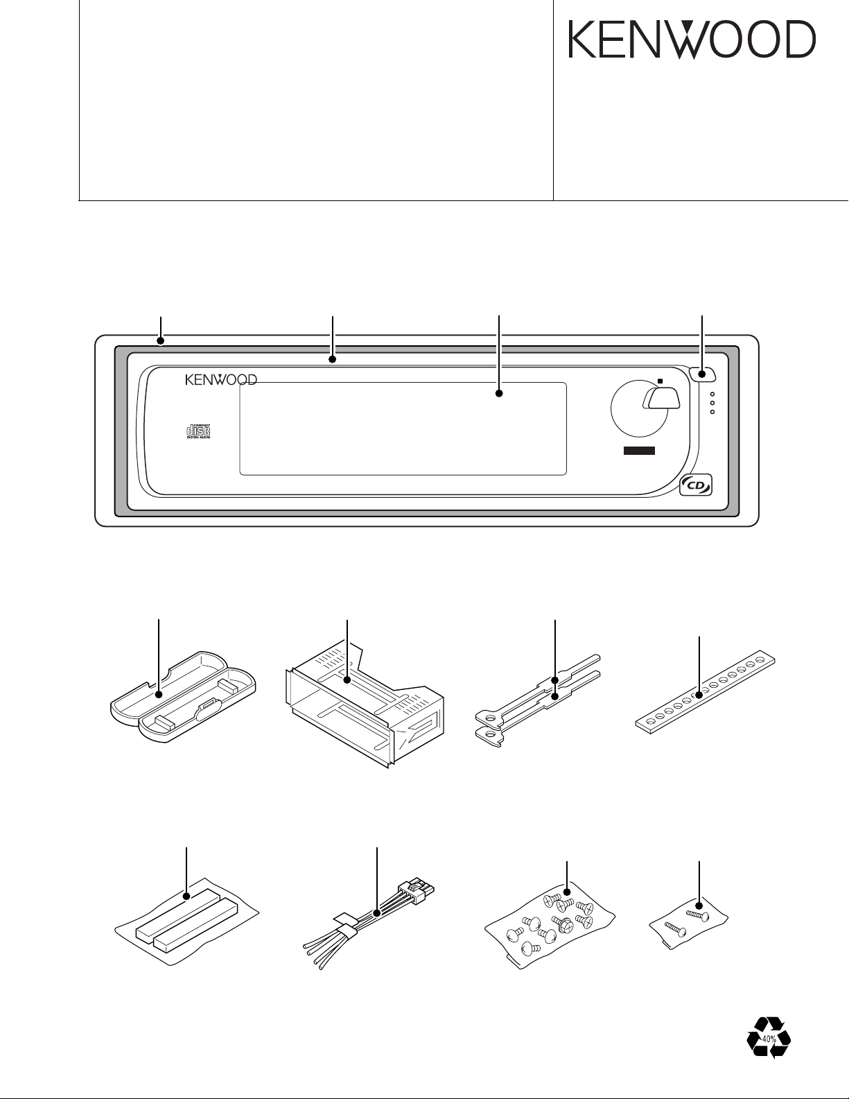
ESCUTCHEON
(B07-2188-02)
DIGITAL OPTMUM
SERVO CONTROL
PLASTIC CABINET ASSY
(A02-1486-13)
PANEL ASSY
(A64-2366-02)
CD PLAYER
60 120 250 380 500 750 1k 2k 4k 8k 16k
KDC-D301
MOUNTING HARDWARE ASSY
(J21-9491-13)
FRONT GLASS
(B10-4055-02)
LEVER x 2
(D10-3031-04)
INTEGRATED QUAD
1BIT D/A
CONVERTER
11BAND
SPECTRUM ANALYZER
KNOB
(K24-1923-14)
MENU
DISP
DPAC
STAY
(J54-0606-04)
: K TYPE ONLY
CUSHION
(G11-1860-05)
DC CORD
(E30-4730-05)
SCREW SET
(N99-1632-05)
: K TYPE ONLY
SCREW SET
(N99-1656-05)
: K TYPE ONLY
KDC-D301
CONTENTS
BLOCK DIAGRAM .............................................................. 2
COMPONENT DESCRIPTION ........................................... 3
MICROCOMPUTER’S DESCRIPTION............................... 5
PC BOARD ......................................................................... 7
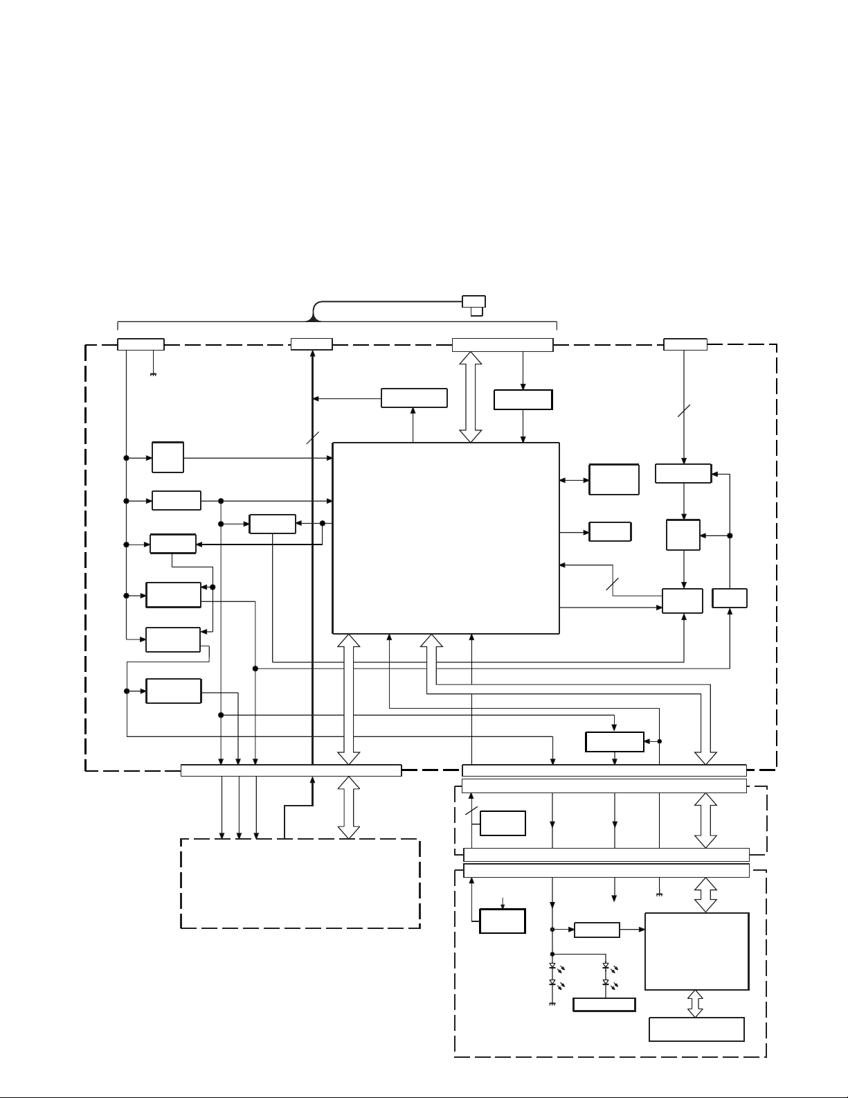
BLOCK DIAGRAM
CH CORD
B.U.
CN1
Q9
B.U.
DET
Q1,2
BU +5V
Q17
SW 14V
Q3,4
AUDIO +B
Q5,6
ILL +B
to H.U.
(X25- )
CN3
L CH
Q19
SW 5V
R CH
2
13PIN
Q14,15,20
AUDIO MUTE
IC1
B.U.DET
VDD
AVDD
P ON
CH CON
SCHEMATIC DIAGRAM ................................................... 13
EXPLODED VIEW ............................................................ 19
PARTS LIST...................................................................... 21
SPECIFICATIONS ...............................................Back cover
SP INPUT
CN2
A MUTE
SYSTEM
MI-COM
DATA H
DATA C
CH CLK
P KEY
REQ H
REQ C
CH CON
EJECT
CH RST
RESET SW
RESET
CH MUTE
BEEP
BPF IN
BPF SEL
BPF A
BPF B
BPF C
IC2
Q16
X1
CLOCK
4.19MHz
Q13
BUZZ
J1
4PIN
4
IC5
ISO AMP
IC6
(1/2)
AGC
AMP
4
IC7
B.P.F.
IC6
(2/2)
VREF
Q7,8
SERVO +B
Q10
CN1
(X89- )
J1
J1
LCD AVR
Q1
DIMMER SW
PAN 5V SW
PAN 5V
PAN 5V
PANEL
IC1
LCD DRIVER
ED1
LCD
CN4
22PIN
2
EJECT
(X92- )
SCL
SDA
BU 5V
L CH
AUD +B
SERVO +B
R CH
SW1
SW2
SW3
MUTE L
RST
STOP
MUTE R
LO/EJ
MO SW
PAN 5V
DISP
CD MECHANISM
2
ILL +B
ILL +B
(X13- )
L CE
L INH
L DATAL
CN5
16PIN
L CLK
KDC-D301
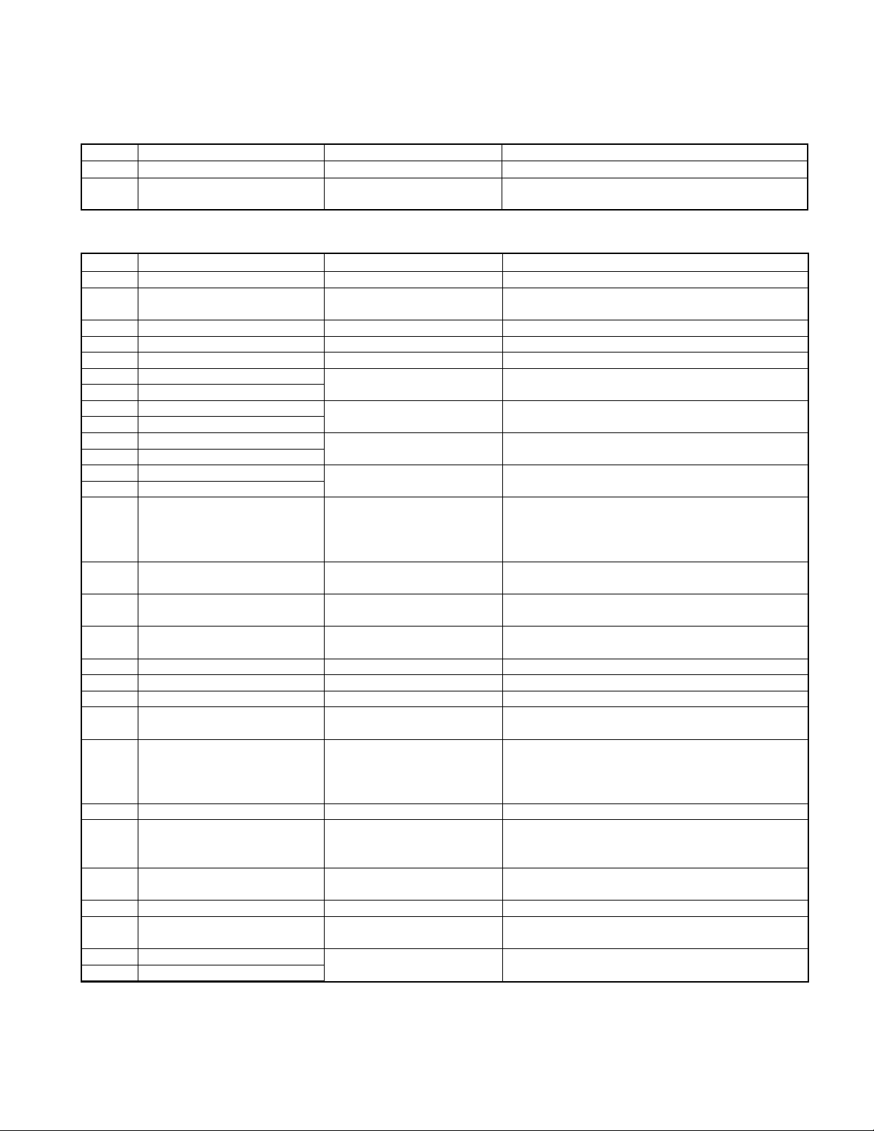
COMPONENT DESCRIPTION
● SWITCH UNIT(X16-110X-XX)
Ref.No. Component Name Application/Function Operation/Condition/Compatibility
IC1 LC75823W LCD driver
Q1 2SC4081 Dimmer SW
● ELECTRIC UNIT(X25-8902-71)
Ref.No. Component Name Application/Function Operation/Condition/Compatibility
IC1 UPD780058GC255 System MI-COM.
IC2 S-80830ANNP Reset IC
IC5 NJM4565M-TE2 Isolation amp.
IC6 NJM4565M-TE2 1/2 VCC & A.G.C.amp.
IC7 BA3834F BPF IC
Q1 2SC4081
Q2 2SA1870 or 2SB1450 Q1 and Q2 are inverted Darlington connection.
Q3 2SC4081
Q4 2SB1202
Q5 2SC4081
Q6 2SB1202
Q7 2SC4081
Q8 2SB1202
Q9 2SC4081 BU detection SW
Q10 2SA1037K Panel 5V SW
Q11 2SC4081
Q12 DTA143EUA Changer mute SW
Q13 DTC144EUA or UN5213 Buzzer SW When a base goes "Hi", Buzzer is turned on.
Q14 DTC343TK Audio mute SW(L Ch) When a base goes "Hi", Audio mute is activated.
Q15 DTC343TK Audio mute SW(R Ch) When a base goes "Hi", Audio mute is activated.
Q16 DTC144EUA or UN5213 Changer reset SW
Q17 UMC2N SW 14V
Q18 DTC144EUA or UN5213 BU detection inverter
Q19 UMC2N SW 5V
Q20 UMC2N Audio mute driver
Q21 2SD2114K AGC Signal level control
Q22 DTC144EUA or UN5213 Changer control SW
Q23 2SA1037K
Q24 DTC144EUA or UN5213 Switch Unit.
BU 5V AVR
Audio +B AVR While Q3's base goes "Hi", AVR outputs +8.0V.
Illumination +B AVR While Q5's base goes "Hi", AVR outputs +10.5V.
Servo +B AVR While Q7's base goes "Hi", AVR outputs +8.0V.
Guide or Eject illumination SW
LED +B SW
When Q1's base goes "Hi", Dimmer LEDs are turned
on.
When BU 5V voltage is less than 3.0V, IC outputs
"Lo".
While BACKUP is applied, AVR outputs +5V.
While BACKUP is applied, a base goes "Hi", and Q12
is turned on.
When momentary power down has detected, a base
goes "Lo", and Q12 is turned off.
When a base goes "Lo" during panel closed, Q10 is
turned on.
When a base goes "Hi", Guide or Eject illumination
LED is lighting-up.
When CHANGER MUTE REQUEST to H/U is worked,
a base goes "Lo" and Q12 is turned on.
When CHANGER RESET from H/U is worked, a base
goes "Hi" and Q19 is turned on.
Audio +8V AVR, Illumination +B AVR, Servo +B AVR
on/off control
When a base goes "Hi", Q17 is turned on, and Each
AVR are working.
CD MECHA. SW, BPF IC on/off control
When a base goes "Lo", Q19 is turned on, and Each
circuits are working.
When a base goes "Hi", Audio mute driver outputs
"Hi".
When CHANGER CONTROL from H/U goes "Hi",
Q15 is turned on.
When Q23's base goes "Hi", BU 5V is supplied to the
3
KDC-D301
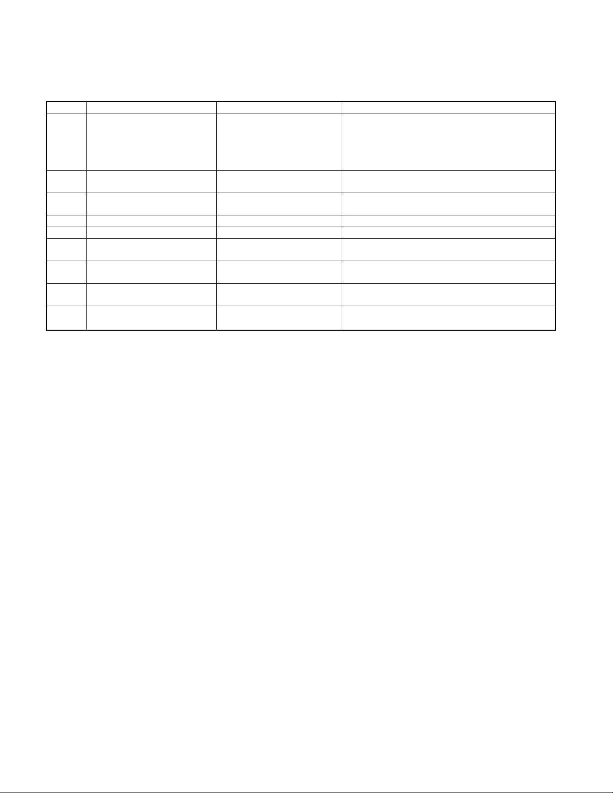
COMPONENT DESCRIPTION
● CD PLAYER UNIT(X32-5010-00)
Ref.No. Component Name Application/Function Operation/Condition/Compatibility
Generation of RF signal based on the signals from
IC1 AN22000AA RF amplifier
IC2 MN662774KG1
IC4 BA5917AFP 4CH BTL driver
IC6 NJM4565MD OP Amp. Low pass filter
Q1 MCH6101 APC LD power control
Q2 DTC124EUA P ON SW
Q3 DTA143XUA A.8V SW
Q4 2SA1362(Y) D.5V SW
Q5 DTC124EUA MOTOR SW
CD signal processor bult-in
MI-COM.
the APC circuit and pickup, and generation of servo
error(focusing error and tracking error)signals.
Detection of dropout, anti-shock, track crossing and
off-track conditions, Gain control function building in.
Focusing coil, tracking coil, spindle motor and sled
motor driver
When CD source is selected, Q2's base goes "Hi",
Q3 and Q4 are turned on.
A8V ON/OFF control. When a base goes "Lo", Q3 is
turnde on.
D5V ON/OFF control. When a base goes "Lo", Q4 is
turnde on.
When CD loading or eject operation is activating, Q5's
base goes "Hi", Q4 is turned on.
4
KDC-D301
MICROCOMPUTER'S DESCRIPTION
IC1 (ELECTRIC UNIT: X25-8902-71)
● Terminal Description
Pin No.
8-10 NC O Not used(N.C.)
30,31 NC O Not used(N.C.)
Pin Name I/O Description Processing Operation
1 EJECT I Eject key input "Lo": Eject key pressed
2 REF CON O A/D converter reference voltage control output "Hi": Reference voltage supplying
3 NC O Not used(N.C.)
4 AVSS - A/D, D/A converter ground connection terminal Connected to ground lines.
5 NC O Not used(N.C.)
6 NC O Not used(N.C.)
7 AVREF1 - D/A converter reference voltage input terminal Connected to BU 5V lines.
11 DATA H I Data input from H/U
12 DATA C O Data output to H/U
13 CH CLK I/O Clock input/output with H/U New type: Input, Previous type: Output
14 REQ C O Communication request to H/U "Lo": Communication request
15 NC O Not used(N.C.)
16 P KEY I Key data input from LCD driver IC
17 L DATA O Data output to LCD driver IC
18 L CLK O Clock output to LCD driver IC
19 NC O Not used(N.C.)
20 NC O Not used(N.C.)
21 MSTOP O Stop request to CD mechanism MI-COM. "Lo": Stop mode, "Hi": Operation mode
22 L INH O INH output to LCD driver IC "Lo": Display lighting-up, "Hi": Display lighting -out
23 L CE O CE output to LCD IC "Hi": Data communication
24 DIMMER O Dimmer output "Lo": Dimmer mode, "Hi": Except dimmer mode
25 NC O Not used(N.C.)
26 BPF SEL O BPF IC control output (SEL,A,B,C)=("Lo",X,X,X)..................GND
27 BPF A O BPF IC band control output A
28 BPF B O BPF IC band control output B
29 BPF C O BPF IC band control output C
32 G ILLUMI O Disc indicator control output
33 VSS1 - Ground connection terminal Connected to ground lines.
34 TYPE1 I Destination selection terminal
35 NC O Not used(N.C.)
36 SDA I/O Data input/output with CD mechanism MI-COM.
37 SCL I/O Clock input/output with CD mechanism MI-COM.
38 NC O Not used(N.C.)
39 CH MUTE O Audio mute request to H/U "Lo": Mute request
40 MUTE O Audio mute control output "Hi": Audio mute on, "Lo": Audio mute off
41 NC O Not used(N.C.)
42 PON O Peripheral circuits AVR control output
43 NC O Not used(N.C.)
44 BEEP O Beep output
45 MRST O Reset output to CD mechanism MI-COM. "Lo": CD mechanism MI-COM. reset
46 CD MUTE I Mute request input from CD mechanism MI-COM. "Lo": Mute request
47 EJ BUP I OR input (EJECT key, B UP inverter signal)
48 NC O Not used(N.C.)
49 MOTOR O CD mechanism loading motor control output "Hi": CD loading/eject action or Break, "Lo": other
50 LOEJ I/O CD mechanism loading/Eject switching output "Lo": Loading, "Hi": Eject, "Hi-Z": Stop or Break
(SEL,A,B,C)=("Hi","Lo","Lo","Lo")......GND
(SEL,A,B,C)=("Hi","Lo","Lo","Hi") ...... 68Hz
(SEL,A,B,C)=("Hi","Lo","Hi","Lo") ...... 170Hz
(SEL,A,B,C)=("Hi","Lo","Hi","Hi") ....... 420Hz
(SEL,A,B,C)=("Hi","Hi","Lo","Lo") ...... 1kHz
(SEL,A,B,C)=("Hi","Hi","Lo","Hi") ....... 2.4kHz
(SEL,A,B,C)=("Hi","Hi","Hi","Lo") ....... 5.9kHz
(SEL,A,B,C)=("Hi","Hi","Hi","Hi") .......14.4kHz
"Hi": Indicator lighting-up, "Lo": Indicator lightingout
J type : Pull down to ground lines
K,E type: Pull up to BU 5V lines
"Hi": A.+8V AVR, ILL +B AVR , SERVO +B AVR
and BPF IC are turned on.
5
KDC-D301
MICROCOMPUTER'S DESCRIPTION
Pin No.
Pin Name I/O Description Processing Operation
51-59 NC O Not used(N.C.)
60 RESET I Reset input "Lo": System reset
61 REQH I Communication request from H/U "Lo": Communication request
62 COMM SW I 5-line communication previous/new switch input "Lo": New type, "Hi": Previous type
63 SW2 I 12cm disc detection terminal(8cm/12cm)
64 SW1 I Loading detection (Loading start) "Lo": Loading start
65 FLIP SW I Panel tilting detection input "Hi": Panel tilted or detached, "Lo": Panel closed
66 CHCON I Changer control input from H/U "Hi": Standby mode, "Lo": Operation mode
67 VSS0 - Ground connection terminal Connected to ground lines.
68 VDD1 - Positive power supply connection terminal Connected to BU 5V lines.
69 X2 - Main clock resonator connection terminal
70 X1 I Main clock resonator connection terminal
71 IC(VPP) - Not used(connected to ground lines)
72 XT2 - Sub clock resonator connection terminal Not used(N.C.)
73 XT1 I Sub clock resonator connection terminal Not used(connected to BU 5V lines)
74 VDD0 - Positive power supply connection terminal Connected to BU 5V lines.
75 AVREF0 I A/D converter reference voltage input terminal Connected to REF CON terminal
76 BPF IN I Level detection input from BPF IC out
77 ILLUMI ON O ILL+B AVR control output "Hi": AVR ON, "Lo": AVR OFF
78 NC O Not used(N.C.)
79 SW3 I Down & limit switch detection input "Hi": Chucking, "Lo": Pickup most inner position
80 B UP I Momentary power down detection input
When 12cm disc is detected, the input becomes
"Lo" temporarily. (Watched in SW1 "Lo")
"Hi" : When momentary power down detected or
BU OFF
"Lo" : BU ON
6
 Loading...