

Kenwood KCA-RC35MR Instruction Manual
WARNING:
FCC
This equipment may generate
modifications to this equipment may cause harmful interference
or
unless the modifications
manual.
unauthorized change
NOTE:
This equipment has been tested and found to comply with the limits
B digital device, pursuant
Class
limits are designed to provide reasonable protection against harmful
interference
harmful
in
used
that interference
this equipment does cause
If
reception, which can
user
the
the following
of
-- Reorient
-- Increase the separation between the equipment and receiver.
-- Consult
THIS DEVICE COMPLIES WITH
OPERATION IS SUBJECT
)THIS DEVICE
(1
(2)THIS DEVICE MUST
INCLUDING INTERFERENCE
OPERATION.
NOTICE:
Class
This
REMARQUE:
appareil
Cet
Canada.
du
could lose
user
The
interference to radio communications, if
accordance with
encouraged
is
or
the
or
a residential installation. This equipment may cause
in
not
will
be
measures:
relocate the receiving antenna.
or
dealer
MAY
apparatus complies with Canadian
digital
B
numeique
use radio frequency energy. Changes
or
instruction
OF
the
FCC
not
is
it
FCC RULES.
THE
TWO
a
equipment
this
Rules. These
installed
no
is
television
or
one or more
by
help.
CONDITIONS:
ICES-003.
norma
Ia
guarantee
NMB-003
expressly approved in
are
the authority to operate
made.
modification
the
occur in a particular installation.
determined
try to correct the interference
to
an experienced radio technician for
NOT CAUSE
ACCEPT ANY INTERFERENCE RECEIVED,
de
is
Part 15 of the
to
instructions. However, there
interference to radio
harmful
turning the equipment off and.on,
by
PART 15
FOLLOWING
THE
TO
HARMFUL INTERFERENCE, AND
MAY CAUSE UNDESIRED
THAT
classe B est conforme
Ia
and
an
if
for a
KENWOOD
KCA-RC35MR
REMOTE CONTROL UNIT
INSTRUCTION
UNITE DE
TELECOMMANDE
MODE D'EMPLOI
CONT-ROL REMOTO
UNlOAD
DE
MANUAL DE
JVC KENWOOD
Resident Only
US
Register
Online
MANUAL
INSTRUCCIONES
Corporation
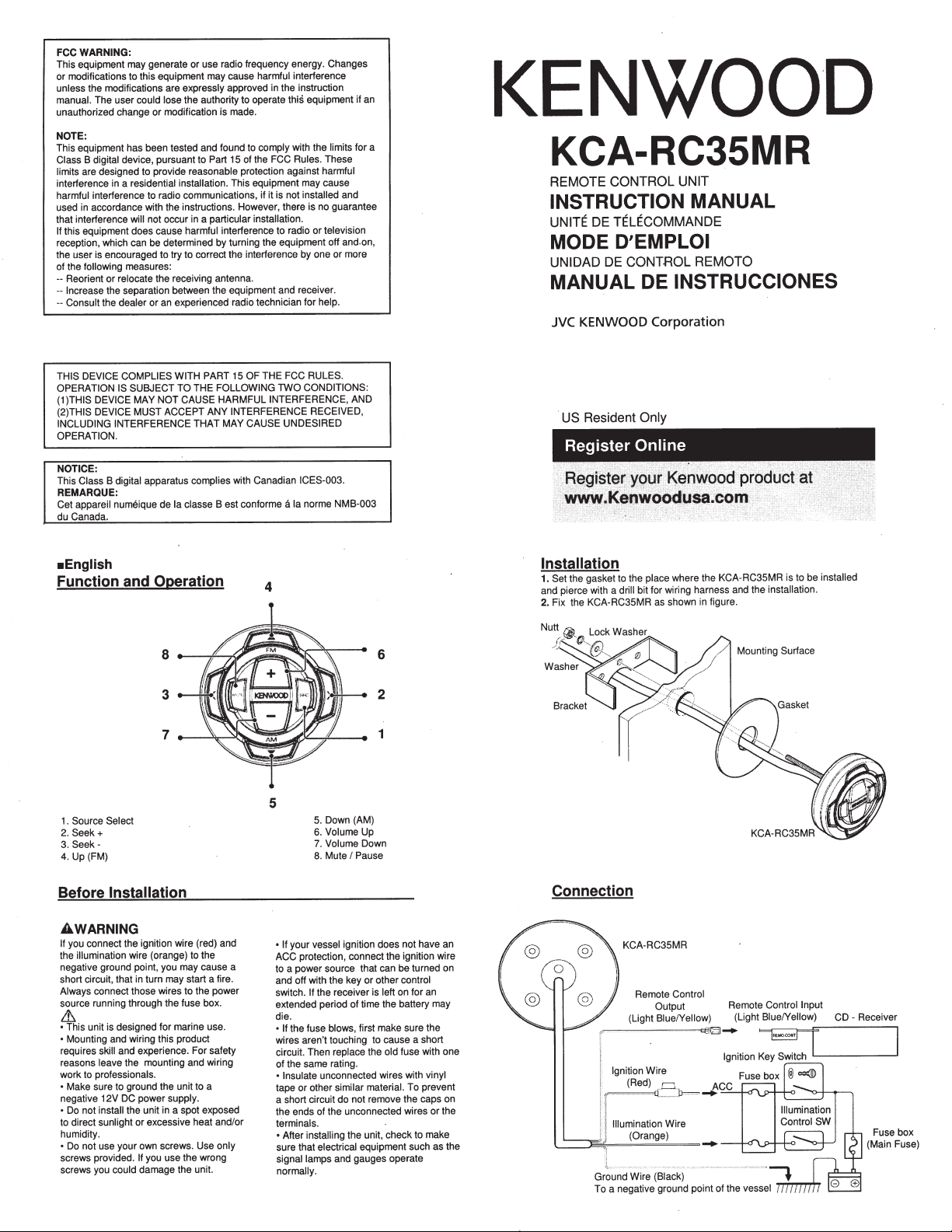
•English
Function and Operation
8
3
7
Source Select
1.
Seek+
2.
Seek-
3.
Up (FM)
4.
Before Installation
WARNING
A
you connect the ignition wire (re
If
illumination
the
negative ground point, you may
short circuit, that in turn may start a fire.
Always
source running through
&
This unit is designed for marine use.
•
Mounting and wiring this product
•
requires
reasons
work to professionals.
Make sure to ground the unit to a
•
negative
Do not
•
to direct
humidity.
not
Do
•
screws provided.
screws you
wire (orange)
connect those wires to the power
and experience.
skill
the mounting and wiring
ve
lea
12V DC power
install
sunlight
use your own screws. Use only
could
in
the unit
excessive heat and/
or
you use
If
damage the unit.
d)
the
to
use a
ca
fuse box.
the
safe
For
supply.
a spot exposed
wrong
the
and
Installation
where the KCA-RC35MR is
the gasket to the
Set
4
1.
and pierce with a
2. Fix the KCA-RC35MR
place
bit for wiring harness and the installation.
drill
as
shown
in
figure.
to
be
installed
6
2
1
5
5. Down (AM)
6.
7.
8. Mute
Volume
Volume
Up
Down
Pause
I
Connection
ignition does not have an
vessel
your
• If
protection, connect the ignition wire
ACC
to a
and
switch.
extended period
die.
• If
ty
wires aren't touching to cause a short
circuit. Then
of
• Insulate
tape
a short circuit
the ends of the unconnected wires
or
terminals.
•
sure that
signal lamps and gauges operate
normally.
source that can
power
off with the key or other control
the receiver is
If
fuse blows, first make sure the
the
the same rating.
other
or
installing
After
time the battery may
of
replace
unconnected wires with
similar material.
not
do
the unit, check to make
equipment such
electrical
left
old
the
remove
turned on
be
for an
on
fuse with one
vinyl
prevent
To
caps on
the
the
or
the
as
KCA-RC35MR
Ground Wire
To
(Black)
a negative ground point of the
Remote
vessel
Control Input
- Receiver
CD
Fuse box
(Main Fuse)

•Fran~tais
Role et Fonctionnement
Installation
1.
Placer
le
4
des
2. Fixer
joint a l'endroit ou KCA-RC35MR sera installe, et percez
trous
pour
le
faisceau
de
fils
et
pour
le
dispositif KCA-RC35MR comme indique sur
!'installation.
le
schema.
8
3
7
1.
Selection de source
2. Recherche vers
3. Recherche vers
4.
Haul
(FM)
le
le
haul
bas
5
Avant !'Installation
AAVERTISSEMENT
sr
vous branchez le cable d'allumage (rouge)
le
cable
de
des
de
montage et
batterie Uaune)
le
cablage
competences
de
mettre l'appareil a Ia
et
masse negatif , vous risquez
court-circuit qui pourrait declench
incendie. Connectez toujours
source d'alimentation passant par
de
fusibles.
&
• Cet appareil est seulement conc;u pour un
utilisation maritime.
• Le montage et
necessite
!'experience. Pour des raisons
securite, laissez un professionnel effectuer le
travail
• Assurez-vous
masse sur une alimentation negative de
cc.
• N'installez pas l'appareil
expose directement
une chaleur excessive ou a l'humidite.
sur
le
point
de
provoquer un
er
un
ces
cables a Ia
le
boitier
de
ce
produit
et
de
de
de
cablage.
dans
a Ia lumiere du soleil, a
un endroit
• N'utilisez pas vos propres vis. N'utilisez
de
vis fournies. L'utilisation
pourrait endommager l'appareil.
• Si l'allumage
de
sur
allumee
interrupteur
allume pendant longtemps, Ia batterie risque de
se vider.
• Si un fusible saute, assurez-vous d'abord que
les cables n'ont pas cause
remplacez
meme valeur.
• lsolez les cables non-Gonnectes
de
12V
eviler
les
connectes au des prises.
Aprils
•
autres dispositifs electriques (feux
signalisation, jauges) fonctionnent normalement.
•Espaiiol
Caracterlsticas y funcionamiento
6
2
1
5. Bas (AM)
6. Volume
haul
7. Volume bas
8. Sourdine I Pause
de
vis incorrectes
de
position ACC, branchez
une
vinyle ou d'un autre materiel similaire. Pour
les
ca
puc
votre vehicule ne dispose pas
le
source d'alimentation
et
eteinte avec
de
corpmande. Si
le
vieux fusible par un nouveau
courts-circuits, ne retirez pas non plus
hons a l'extremite des cables non-
avoir installe l'appareil, venfiez que les
cable d'allumage
qui
Ia
cle ou
le
de
court-circuit puis
que
peut etre
avec
un autre
recepteur reste
de
avec
un ruban
de
le
L:==~~~~~~~
KCA-RC35MR
Fil d'allumage
(Rouge)
, _
__
-e...J=-
lir
Fil
~:~~~;
· 1 (Orange)
L
..
----~~-
Fil
de
masse (Noir) · •
a
un
Relier
vehicule ·
point de masse negatif
...:cc
a;de
9
-.
-
--~----
--------
Entre
de
te!ecommande
(Bieu clair/Jaune) Recepteur CD
---~--
·--<>
.....,
du
Boitierde
fusible
(Fusible
principal)
lnstalacion
1.
Coloque Ia junta donde
con
un taladro para poder pasar el cableado y realizar
2.
Fije Ia unidad KCA-RC35MR como se muestra
se
encuentre
Ia
unidad KCA-RC35MR y perfore
en
Ia flgura.
Ia
instalaci6n.
8
3
7
1 . Encendido
2. Busqueda +
Bu
squeda-
3.
4. Arriba (FM)
Antes de Ia instalacion
AADVERTENCIA
Si conecta el cable
cable de bateria (amarillo) al punta
negative, puede provocar un cortocircuito
que, a su vez, puede originar
Conecte siempre esos cables a
alimentaci6n que pasa por Ia caja
&
• Esta unidad esta disefiada
maritima.
• El montaje y cableado de este producto
debe realizarlos un profesional cualificado y
con experiencia. Par motives
Ia
labor de instalaci6n y montaje en
deje
manes de profesionales.
• Asegurese de conectar a tierra Ia unid
con una fuente
12VCC
.
No
insta
•
Ia luz solar
humedad excesivos.
No
use sus propios tornillos. Utilice solo los
•
tornillos in
diferentes podrfa
principal.
de
de
alimentaci6n negativa
te
Ia unidad
dir
ecta a
en
cl
uidos. El uso
ca
usar
encendido (raja) y el
en
un spot expuesto a
entornos con calor o
daiios
de
s61o
tornillos
de
un
incendio.
Ia
fuente
de
para usa
de
seguridad,
en Ia unidad
tierra
fusibles.
ad
de
de
6
2
1
5. Abajo (AM)
6. Aumentar Volumen
5
7. Disminuir Volumen
8. Silenciado I Pausa
• Si el soporte de encendido no tiene una
posicion ACC, conecte el cable
una
fuente
de
encenderse y apagarse mediante
otro interrupter de control. Si se deja encendido
el receptor durante un periodo
prolongado, es posible
• Si el fusible se dispara, compruebe
cables
cortocircuitos y sustituya el fusible antiguo par
uno nuevo
• Enrolle
de
vinilo u otro material similar para q
ais
lados. Para evitar cortocircuitos, no retire las
tapas
terminales no conectados.
• Despues
el equipam
indicadoras o los calibradores, funciona
correctamente
alimentaci6n para
no
estan
en
contacto para evitar
de
Ia misma clasificaci6n.
los
cables no conectados con una cinta
de
los extremes
de
instalar
ie
nto electrico, como
de
encendido a
que
pueda
una
llave u
de
que
de
Ia
tiempo
Ia
baterfa se agate.
que
ue
los
cables o
unidad, compruebe que
las
lamparas
los
queden
r--~
1
I (Raja)
~-~
!'
L:_.Jili!.
~.;._....;,._....;..,;,_
II
c;ilieal'i.lrffi
Hacia un punto de
KCA-RC35MR
Salida de Control Entrada
Remota Remota Unidad Principal
ar
-----
:
lgnici6n Caja
_ _
(Ne"Qr-0)·
------~-
Tierra
Cable
(Celeste/Am
-
de
Cable de
lluminaci6n
(Naranja)
Superficie
KCA-RC35MR
illo)
(Cele:.s
:orde
:;::r
Fusibles
-ACC
en
el chassis
de
de
... t
__
ei
__ A __
m.,.a_ri=l
de
-,
Montura
Control
lloi)
L
_____
_____
1
__,
de
Caja
Fusibl
es
(Fusible
Principal)
 Loading...