

CD CASSETTE DSP RECEIVER
DPX-5050
SERVICE MANUAL
P
S
D
DIGITAL
SIGNAL
PROCESSOR
AUD
EQ
FM+
B NR
DISC
SCRL 1 SCN 2 RDM 3 REP 45M. RDM 6
USER B.S METAL
CD CASSETTE DSP RECEIVER
© 2003-4 PRINTED IN JAPAN
B53-0044-00 (N) 153
OPEN
DISP
DIGIT
DPAC
ATT
COMPACT
AL A
NAME.S
PWR
OFF
UDIO
FNC
CD-R/CD-RW
AVAILABLE
CRSC
SRC
S.A
DOLBY B NR
DIGITAL
PULSE
AXIS
CONTROL
Refer to the Destination "M1" of service manual DPX-4020's parts list (B51-7776-00)
except the following parts.
PARTS LIST
New Parts
✽
Ref. No. d e Parts No. Description Ref. No. d e Parts No. Description
AN
dw
250 2E✽K24-4084-03 KNOB (CD EJECT)
251 2E
254 3H
255 1H K25-1288-03 KNOB (CASSETTE EJECT)
256 3H K25-1467-02 KNOB (SRC)
257 2H K25-1468-02 KNOB (SEEK)
258 3H K25-1469-02 KNOB (FM)
259 3H K25-1470-03 KNOB (VOL)
260 3H K25-1471-02 KNOB (1-6)
271 1F N99-1724-05
204
205
PA1
213
-
DPX-5050
3E
A22-3020-02 SUB PANEL ASSY 252 3H K24-3891-03 KNOB (DSP)
✽
3E
A22-3021-01 SUB PANEL 253 3H K24-3892-03 KNOB (EQ)
✽
A64-3125-02 PANEL ASSY
3G
✽
B10-4429-01 FRONT GLASS
3G
✽
H54-2914-03 ITEM CARTON CASE
✽
AN
dw
K24-4086-03 KNOB (OPEN)
✽
K24-4085-03 KNOB (SA)
✽
SCREW SET
©
2001-5 PRINTED IN JAPAN
B51-7776-00 (N)1734
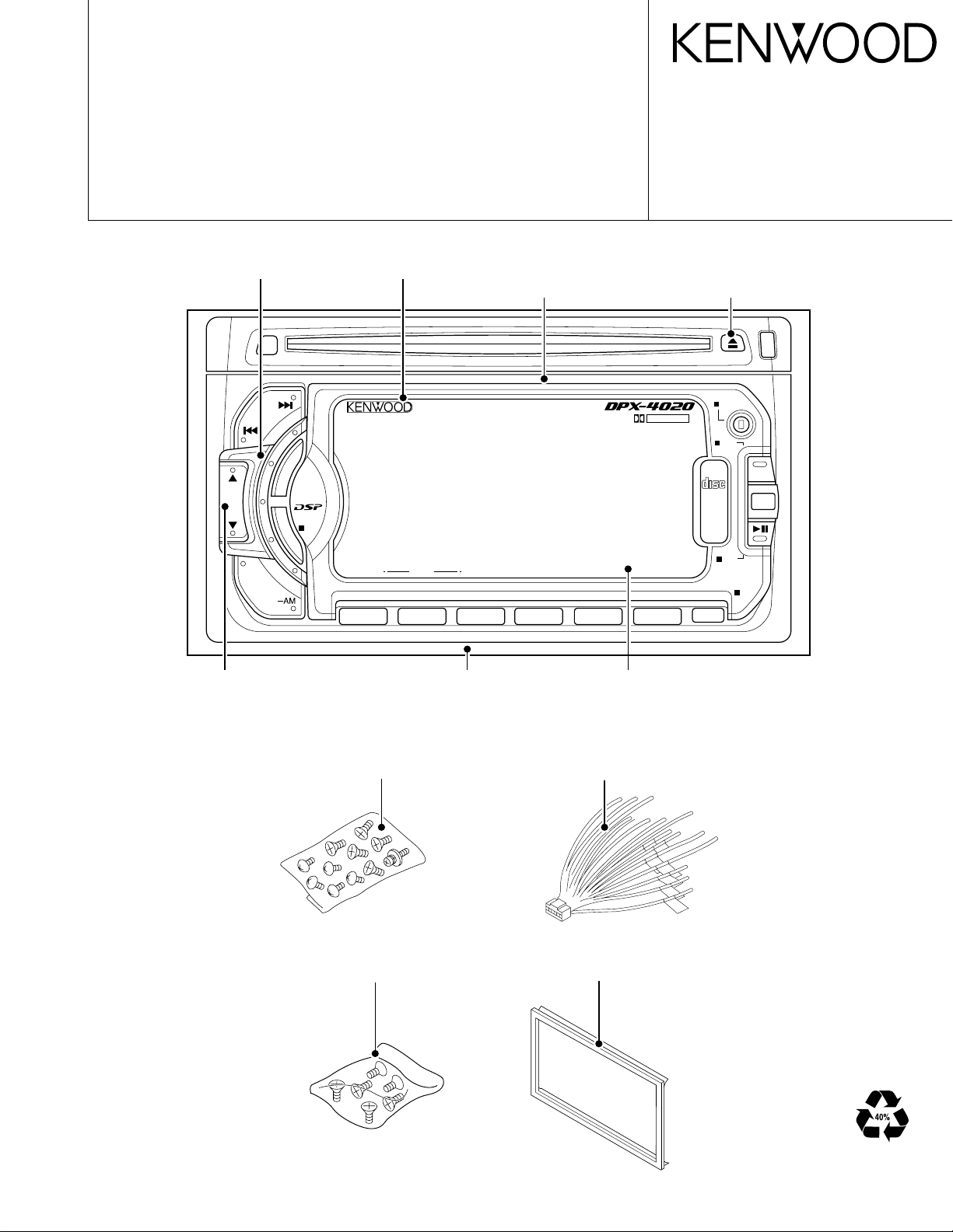
CD CASSETTE DSP RECEIVER
DPX-4020
SERVICE MANUAL
AUD
DIGITAL
SIGNAL
PROCESSOR
D
S
P
EQ
FM+
DISC
B NR
SCRL 1 SCN 2 RDM 3 REP 45M. RDM 6
ATT
USER B.S METAL
DISP
DIGITAL
PULSE
AXIS
CONTROL
NAME.S
PWR
OFF
FNC
CD-R/CD-RW
AVAILABLE
TI
SRC
S.A
CD CASSETTE DSP RECEIVER
OPEN
DPAC
COMPACT
DIGITAL AUDIO
DOLBY B NR
Screw set
(N99-1701-05) : M type
DC cord
(E30-4939-05)
Screw set
(N99-1711-05) : K type
Knob (VOL)
(K25-1302-03)
Escutcheon assy
(B07-3046-04)
Front glass
(B10-4063-01) : K type
(B10-4064-01) : M type
Escutcheon assy
(B07-3047-04) : K type
Panel assy
(A64-2383-02) : K type
(A64-2384-02) : M type
Knob (CD EJ)
(K24-3716-03) : M type
(K24-3717-03) : K type
Badge
(B43-1284-04)
Dressing panel
(A21-4102-02)
DPX-4020
2
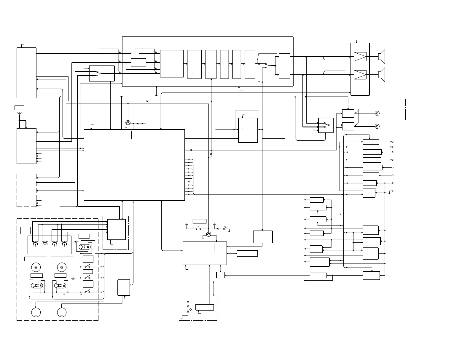
SWITCH UNIT
(X25-8970-00)
DOLBY UNIT
(X87-3040-00)
CASSETTE MECHA
CD MECHA
(X16-1250-00)
SUB PANEL UNIT
SYSTEM u-CON
MN101C15
VOL
BASS
INPUT
SEL
ISO
NC. MPX
PWR AMP
FRONT
SP OUT
REAR
SP OUT
MUTE
TC4066FB
ANALOG SW
TA8263BH
PRE OUT
FRONT
FRONT/REAR/N-F (J TYPE)
PRE OUT
E VOL, TONE, NC, MPX TDA7407
TRE
MD/CD
CHANGER
DSP
M65849BFP
VFD
PANEL u-CON
REMOCON
KEY MATRIX
VOL
SOFT
MUTE
MN101C10
AMP-CTRL
ANT CON
CXA2560Q
LB1641
F/E
ANT.
PLAY
HEAD
MODE
PAC K
DET
STBY
PAC K
IN
TAKEUP REEL SUPPLY REEL
REELT REELS
MID
RST SW
BPF
ANALYZER
SPECTRUM
BA3129F
SW OP
MUTE
(K,M) TYPE ONLY
REAR/N-F (K,M TYPE)
NAVI MUTE
SMALL DET
ACC DET
BU DET
5V AVR
FM8V SW
AM8V SW
P CON
5V AVR
5V SW
MOTOR SW
MAIN
A8V AVR
BU5V AVR
+7.5V
CD SRV
AVR
DC/DC +B
SW
DC/DC +B
SDA
SCL
RESET
FSD OUT
FM SD
PWR SVR
PWR STBY
PWR TEST
MUTE
AUDIO OUT
SCL
FM SD
FSD
SDA
AM ANT
FM ANT
AUD +B
FM +B
AM +B
F/E 5V
SW1-3
MRST
CD MOTOR
ANT CON
P CON
LINE MUTE
ILLUMI
ACC
B. U
GND
P MUTE
BU DET
ACC DET
ILL CON
LANP
P CON
BU 5V
CD CH
+6dB
0dB
DSP 5V
FL +BBU 5V
LED +B
AM
FM
FM +B
AM +B
LED +B
F/E 5V
B. U
B.U
BU 5V
AUD +B
SDA
SCL
PON 5V
BUZZ
DSP STBY
DSP DATA
DSP CLK
(-0.5dB)
AUDIO OUT
AMP CTRL
AMP-CTRL
P CON
MOTOR +B
CD SRV +B
DSP 5V
AUDIO +B
BUZZ
PWR STBY
PWR TEST
PWR SVR
SCL
SDA
FRONT
REAR
FM
AM
+10dB
P ANT
BU 5V
PN SC CON
PN SC REQ
PN SC DATA
PN MC REQ
CD MUTE
CD LO/EJ
CD MSTOP
F-IN(L)
VREF
R-IN(L)
F-IN(R)
R-IN(R)
SUB
MOTOR
DRIVER
SUB
MAIN
REV
RchRch
FWD
Lch
REV
Lch
FWD
A OUT
AM : +3dB
CAS : +0dB
FM : +1dB
CD CH : +2dB
CH DATA H
CH CON
CH REQ H
CH REQ C
CH DATA C
CH CLK
RESET
MUTE
CD SRV +B
BU 5V
AUD +B
BU 5V
AND +B
CD SRV +B
MOTOR +B
AUD +B
SW
INPUT
PREOUT
NON-FAD
PWR MUTE
DSP-DATA
DSP-STBY
DSP-CLK
P ON
P ANT
BU DET
ACC DET
AMP CTRL
P MUTE
FM
u MUTE
LAMP
ILL CON
AM
MIAN-M
PN MC CLK
PN MC DATA
C SUB M-
C SUB M+
R REEL
F REEL
C MODE 3
C MODE 2
C MODE 1
C MUTE
C MSC
C MUSIC
C F/R
C MTL
C NR
SW1-3
MRST
CD MSTOP
CD MOTOR
CD LO/EJ
CD MUTE
MPX OUT
DSP OFF
-4dB
DSP ON
-4dB
-12dB +15dB
CAS
PWR MUTE
+10.6dB
RESET
PN MC REQ
PN MC CLK
PN MC DATA
PN SC CON
PN SC DATA
PN SC REQ
REMOCON
AUD +B
FRONT
REAR
PREOUT
NON-FAD
(-0.5dB)
CPH3105
CPH3105
PON 5V
BU 5V
MAIN-M
P ON
SUB PANEL
CH REQ H
CH CLK
CH DATA C
CH REQ C
CH DATA H
CHCON
MM
CAS : 440mV
AM : 170mV
FM : 340mV
CD CH : 1200mV
AM : 170mV
FM : 340mV
CD : 1200mV
CD CH : 956mV
FM : 480mV
CAS : 277mV
AM : 151mV
CAS : 440mV
CD CH : 1200mV
AM : 170mV
FM : 680mV
DSP OFF
AM : 477mV
FM : 1516mV
CAS : 1557mV
CD CH : 3010mV
(STADIUM)
AM : 202mV
CAS : 370mV
FM : 680mV
CD CH : 1270mV
DSP ON
AM : 120mV
(STADIUM)
FM : 381mV
CAS : 220mV
CD CH : 756mV
DSP ON
CD CH : 2858mV
FM : 1431mV
AM : 450mV
CAS : 440mV
BLOCK DIAGRAM

DPX-4020
3
● SYNTHESIZER UNIT (X14-6710-XX)
COMPONENTS DESCRIPTION
Ref.No.
Component Name Application/Function Operation/Condition/Compatibility
IC1 MN101C15FCP System micom
IC2 TDA7407 Electronic volume
IC3 TC4066BF(N) Analog SW Voice signal input switching (CD,.MD,CASSETTE)
IC4 M65849BFP DSP IC
IC5 BA3129F Switching ope-amplifier Voice signal output switching (FRONT
,.
REAR)
IC7 TA8263BH PWR IC
IC8 LB1641 Motor driver For cassette mechanism sub-motor
IC9 PST9135NR Reset IC Reset 3.5V voltages
IC10 TC7W02FU Logic IC(OR) Rogic circuit for MUTE
IC11 M5237ML Power source IC Reg for A8V
Q1 2SC4081 Power source SW for F/E VDD 5V ON:F/E VDD 5V output
Q2 CPH3105 Power source SW for FM ON:FM+B 8V output
Q3 CPH3105 Power source SW for AM ON:AM+B 8V output
Q4 FMG1A Power source control SW for FM/AM ON:FM+B/AM+B 8V output
Q101 2SB1443 Power source SW for main motor ON:Main motor ON
Q102 DTC144EK Power source control SW for main motor ON:Main motor ON
Q201 DTC143TK MUTE SW
Q202 DTC143TK MUTE SW
ON:MUTE
Q301 DTC143TK MUTE SW
Q302 DTC143TK MUTE SW
Q401 DTC124EUA SW for electronic volume mute ON:MUTE
Q402 FMC2A SW for analog switch control
Q403 DTC144EUA SW for switching ope-amplifier control
Q404 DTC144EUA SW for power IC mute terminal contorol ON:Temperature protection OFF (Test mode)
Q405 DTA114EUA Control terminal for MUTE (preout) ON:MUTE
Q406 DTA114EUA Control terminal for MUTE (preout) ON:MUTE
Q407 DTA114EUA SW for electronic volume mute ON:MUTE
Q601 DTC114YUA SW for system micom reset ON:REEST
Q602 DTA124EUA SW for RESET IC output ON:REEST
Q701 DTC144EUA SW for BU serge detection ON:Serge(power down)
Q702 FMW1 SW for BU/ACC detection ON:Power down
Q703 DTC144EUA SMALL detection SW ON:SMALL ON
Q705 DTA124EUA SW for external amplifier control
Q706 2SB1277(Q,R) SW for P-CON ON:P-CON output
Q707 2SA1037K
SW for P-CON over-electric current protect
ON:Stop P-CON output
Q708 DTA124EUA
Control
SW for P-CON over-electric current protect
ON:Stop P-CON output
Q709 DTC114YUA Control switch for P-CON ON:P-CON output
Q710 2SB1277(Q,R) SW for P-ANT ON:P-ANT output
Q711 DTC114YUA Control switch for P-ANT ON:P-ANT output
Q712 2SB1548(P) Power source switch for BU 5V
Q713 2SC4081
Power source switch for BU 5V (Darling ton)
Q714 IMD16A Power source switch for PON 5V ON:PON 5V output
Q715 FMC2A
Power source control switch for analog+B
ON:Analog+B 8V output
Q716 2SB1548(P) Power source switch for analog+B ON:Analog+B 8V output
Q717 2SD1766 Power source switch for DSP+B ON:DSP+B 5V output
Q718 FMC2A Power source control switch for servo+B ON:Servo+B 7.5V output
Q719 2SB1548(P) Power source switch for servo+B ON:Servo+B 7.5V output
Q720 2SC4081
Power source switch for servo+B(Darling ton)
ON:Servo+B 7.5V output
Q724 2SB1548(P) Power source switch for servo+B ON:Servo+B 7.5V output
Q901 FMC3A
Power source control switch for ILLUMI+B
ON:ILLUMI+B 14.4V output
Q902 2SB1446
Power source switch for ILLUMI+B (Darling ton)
ON:ILLUMI+B 14.4V output
Q903 2SC4081 Power source switch for ILLUMI+B ON:ILLUMI+B 14.4V output

DPX-4020
4
● SUB CIRCUIT UNIT (X16-1250-00)
Ref.No.
Component Name Application/Function Operation/Condition/Compatibility
IC1 SBX-3050 Remote control IC Light receive port of remote controller
● DOLBY UNIT (X87-3040-00)
Ref.No.
Component Name Application/Function Operation/Condition/Compatibility
IC1 CXA2560Q DOLBY IC PRE-AMP/DOLBY-EQ
Q1 KRC103S
Between-music detection level adjustment FF/REW
FF/REW ON
● SWITCH UNIT (X25-8970-00)
Ref.No.
Component Name Application/Function Operation/Condition/Compatibility
IC1 MN101C10AAL Panel micom Display mechanism & key matrix control
IC2 BA3830F BAND PASS IC (Spectrum analyzer)
Signal data from X14 are displayed with
strength of frequency
Q1 DTC114EUA RST switch H:RST
Q2 2SK3018 Analog signal AGC Auto gain control of analog signal
Q3 UMC3N SW5V H:ON
Q4 FMC4A SW for VFD logic power source H:ON
Q5 DTC114EUA VFD branking control H:ON
COMPONENTS DESCRIPTION

DPX-4020
5
● SYSTEM µ-COM (IC1:X14-6710-XX) MN101C15FCP
Pin.No.
Pin name I/O Description
Processing Operation
1 VREF- - Connected to GND.
2 NC I Not used. Connected to GND.
3 FM_SD I FM SD input.
4 F_REEL I Reel pulse (FWD) detection. Hi-Z
5 R_REEL I Reel pulse (REV) detection. Hi-Z
6 NC I Not used. Connected to GND.
7 ACC_DET I Acc detection input.
8 SMALL I SMALL detection input.
9 LINE MUTE I LINE MUTE detection input.
10 VREF+ - A/D converter. Reference voltage input terminal.
11 VDD - Main power input.
12 X' Tal (8.38) O Connected to main clock.
13 X' Tal (8.38) I Connected to main clock.
14 VSS - Connected to GND.
15 XI I Connected to GND.
16 XO O Open.
17 MMOD I Connected to GND.
18 PN_MC_DATA O Data output to panel micom.
19 PN_SC_DATA I Data input from panel micom.
20 PN_MC_CLK O Clock output to panel micom.
21 CH_DATAH O Data output to CD-CH.
22 CH_DATAC I Data input from CD-CH.
23 CH_CHCLK I/O
Previous bus : Data input from CD-CH. New bus : Data output to CD-CH.
24 BEEP O Beep output.
25 RESET I System reset.
26 CH_REQH O Send request output to CD-CH.
27 CH_CON1 - Operation control of CD-CH1.
28 CH_CON2 - Operation control of CD-CH2.
29 P_ANT - Power ANT control.
30 P_CON - External amplifier power control.
31 BU_DET I Back up detection input.
32 CH_REQC I Send request input from CD-CH.
33 PN_SC_REQ I Send request input from panel micom.
34 SEL1 - IC2$ noise cancellation selection.
35 SEL2 - IC2$ noise cancellation selection.
36 SDA I/O I2C data input/output.
37 NC - Not used. (Open)
38 SCL O I2C clock output.
39 P_ON - Internal power control.
40 LAMP - Key illumination control.
MICROCOMPUTER'S TERMINAL DESCRIPTION

DPX-4020
6
Pin.No.
Pin name I/O Description
Processing Operation
41 PN_MC_REQ O Send request output to panel micom.
42 PN_SC_CON O Operation control output of panel micom.
43 NON_FAD O Control Non-Fad output. (ON/OFF)
44 MUTE O Audio mute output.
45 TYPE1 I Destination type input.
46 TYPE2 I Destination type input.
47 PNL_OPEN - Panel open detection.
48 C_SUB_M- O C mechanism loading motor control. L
49 C_SUB_M+ O C mechanism loading motor control. L
50 C_MAIN_M O C mechanism motor control. L
51 C_MODE3 I Sub-motor control SW3 (pack-in detection). Hi-Z
52 C_MODE2 I Sub-motor control SW2. Hi-Z
53 C_MODE1 I Sub-motor control SW1. Hi-Z
54 CD_SW1 I Input from CDSW1.(loading start SW)
55 CD_SW2 I Input from CDSW2.(12cm disc detection SW)
56 CD_SW3 I Input from CDSW3.(down &limit switch)
57 CD_LO/EJ - CD mechanism loading motor control .(LO/EJ)
58 CD_LMON - CD mechanism loading motor control .(ON/OFF)
59 CD_MSTOP O Stop output to CD mechanism computer.
60 CD_MRST O Reset output to CD mechanism.
61 CD_MUTE I Mute input from CD mechanism.
62 C_MUTE O EQ mute selection SW. L
63 C_F/R O FWD/REV selection. L
64 C_MSC O Between-music detection mode control. L
65 C_NR O DOLBY control.(ON/OFF) L
66 C_MS_IN I Between-music pulse detection input. Hi-Z
67 C_MTL O METAL control.(ON/OFF) L
68 DSP_DATA O Data output to DSP.
69 DSP_CLK O CLK output to DSP.
70 DSP_STB O Latch output to DSP.
71 INPUT - Control input selected SW.
72 NC - Not used.
73 FM+B - FM power.
74 AM+B - AM power.
75 FSD_OUT - Station-meter detection.
76 TEST - Power IC control.
77 PW_MUTE - Power IC mute control.
78 PWIC_STBY - Power IC standby control.
79 PWIC_SVR - Power IC control.
80 AMP_CTRL - External amplifier control.
MICROCOMPUTER'S TERMINAL DESCRIPTION

DPX-4020
7
● PANEL µ-COM (IC1 : X25-8970-00) MN101C10AAL
Pin.No.
Pin name I/O Description
Processing Operation
1 ANA4 I Spectrum analyzer input.(1kHz) H(Hi-Z)
2 ANA5 I Spectrum analyzer input.(3.3kHz) H(Hi-Z)
3 ANA6 I Spectrum analyzer input.(10kHz) H(Hi-Z)
4 NC I Not used. Connected to GND. L(Hi-Z)
5 NC I Not used. Connected to GND. L(Hi-Z)
6 VREF+ I A/D converter. Reference voltage input terminal. -
7 VDD - Main power input. -
8 OSC2 - Main clock connection.(16.0MHz) -
9 OSC1 - Main clock connection.(16.0MHz) -
10 VSS - Connected to GND. -
11 XI I Connected to GND. L
12 XO O Not used.(Open) -
13 MMOD I Connected to GND. L
14 PN_SC_DATA O System computer communication.Data output terminal. L
15 PN_MC_DATA I System computer communication.Data input terminal. H/L(Hi-Z)
16 PN_MC_CLK I System computer communication.Clock input terminal. H/L(Hi-Z)
17 VFD_DATA O VFD driver data output. L
18 NC O Not used.(Open) L
19 VFD_CLK O VFD driver clock output. L
20 VFD_LAT O VFD driver latch output. L
21 RST I Reset input. -
22 VFD_BK O VFD driver blank output. L
23 NC O Not used.(Open) L
24 PON O P-ON 5V control. L
25 NC O Not used.(Open) L
26 PN_SC_REQ O System computer communication.Send request output. L
27 PN_MC_REQ I System computer communication.Reception request input. H(a)(Hi-Z)
28 PN_SC_CON I System computer communication.Panel operation control. H(a)(Hi-Z)
29 REMOCON I Remote control signal input. -
30 KR0 I Key-return signal input 0. -
31 KR1 I Key-return signal input 1. -
32 KR2 I Key-return signal input 2. -
33 KR3 I Key-return signal input 3. -
34 KR4 I Key-return signal input 4. -
35 KR5 I Key-return signal input 5. -
36 NC O Not used.(Open) L
37 KS0 O Key-scan signal output 0. L
38 KS1 O Key-scan signal output 1. L
39 KS2 O Key-scan signal output 2. H
40 KS3 O Key-scan signal output 3. H
41~60 NC O Not used.(Open) L
61 VREF- I Connected to GND. L
62 ANA1 I Spectrum analyzer input.(63Hz) H(Hi-Z)
63 ANA2 I Spectrum analyzer input.(150Hz) H(Hi-Z)
64 ANA3 I Spectrum analyzer input.(330Hz) H(Hi-Z)
MICROCOMPUTER'S TERMINAL DESCRIPTION
DPX-4020
8
■ How to enter the test mode
While pressing on DSP + EQ or DSP + AM keys, press
SRC key. It is possible to enter the test mode in this manner.
■ Test Mode Condition
When booted with all OFF.
The value for the volume is -10dB. (On display: 30)
Beep disabled.
All lights display.
CRSC: OFF (Only K/M type)
DSP: Bybass
EQ: Flat
SEP/ANA: Peak hold
However, when entering the test mode with DSP + AM key,
the volume value will be -30dB with beep enabled.
The beep enable condition is such that, regardless of effective
keys and non-effective keys, beeps are effective whenever
keys are pressed.
■ Test Mode (Display)
Since there are many segment numbers in the display
section, bridging with other segments can be confirmed (Only
when the source condition is in all OFF.)
■ Test Mode (Source: CD)
When the disk is loaded, track No. 9 is the first track to be
played.
The following keys are operated only when the source is CD.
When there are changes in the track numbers being played in
other cases, the playing is continued.
>>| key selects only certain tracks.
|<< key selects by going down the tracks, as with the regular
operation.
■ Test Mode (EQ Adjustment)
When displaying the source, by pressing EQ/AUD once
quickly, adjustment mode is entered.
When 1 key is press: Flat
When 2 key is pressed: Full boost
Whne 3 key is pressed: Full cut
■ The settings for Q, Feq, Ex are fixed.
Bass Q 2.0
Feq 150Hz
Ext ON
Mid Q 2.0
Feq 1kHz
Treble Feq 10KHz
■ Test Mode (Audio Adjustment)
While displaying the source, by pressing EQ/AUD key in an
elongated manner, adjustment mode is entered. By
continuing with FM , AM key, the following items may be
selected and I<< and >>I keys can be used for adjustment.
∗ For balance adjustment, three steps of Right ,. Center ,. Left
are set. (L15, R15)
∗ For fader adjustment, three steps of Front ,. Center ,. Rear
are set. (F15, R15)
∗ For the amplifier control, OFF ,. 2
∗ Test Mode (Function at the time of ALL OFF Source)
By pressing PLAY/PAUSE key in an elongated manner
during each sources, adjustment mode can be entered and
the following items are selected with AM , FM keys.
Adjustment will be conducted with |<< and >>| keys.
The following are added to each source functions (including
CD and TAPE).
For Preout adjustment, Front ,. Rear ,. N-F
∗ Preout adjustment is the first item.
■ Releasing the Test Mode
Test mode is released by RESET, ACC OFF/ON, Power
OFF/ON.
Also, Source, Tuner, and Audio are returned to initial condition
by ACC OFF and Power OFF.
■ Backup current measurement compatible
Regardless of the test mode, when reset at ACC OFF
condition (Backup is ON), MUTE will go OFF after two
seconds. (The peripherals are not powered off unlit the
CD/MD mechanism stops, it takes 2 seconds plus alpha.)
Adjustment
This model has no adjustment items.
Tuner section adjustment is conducted for individual F/E and
adjustment cannot be conducted on a set.
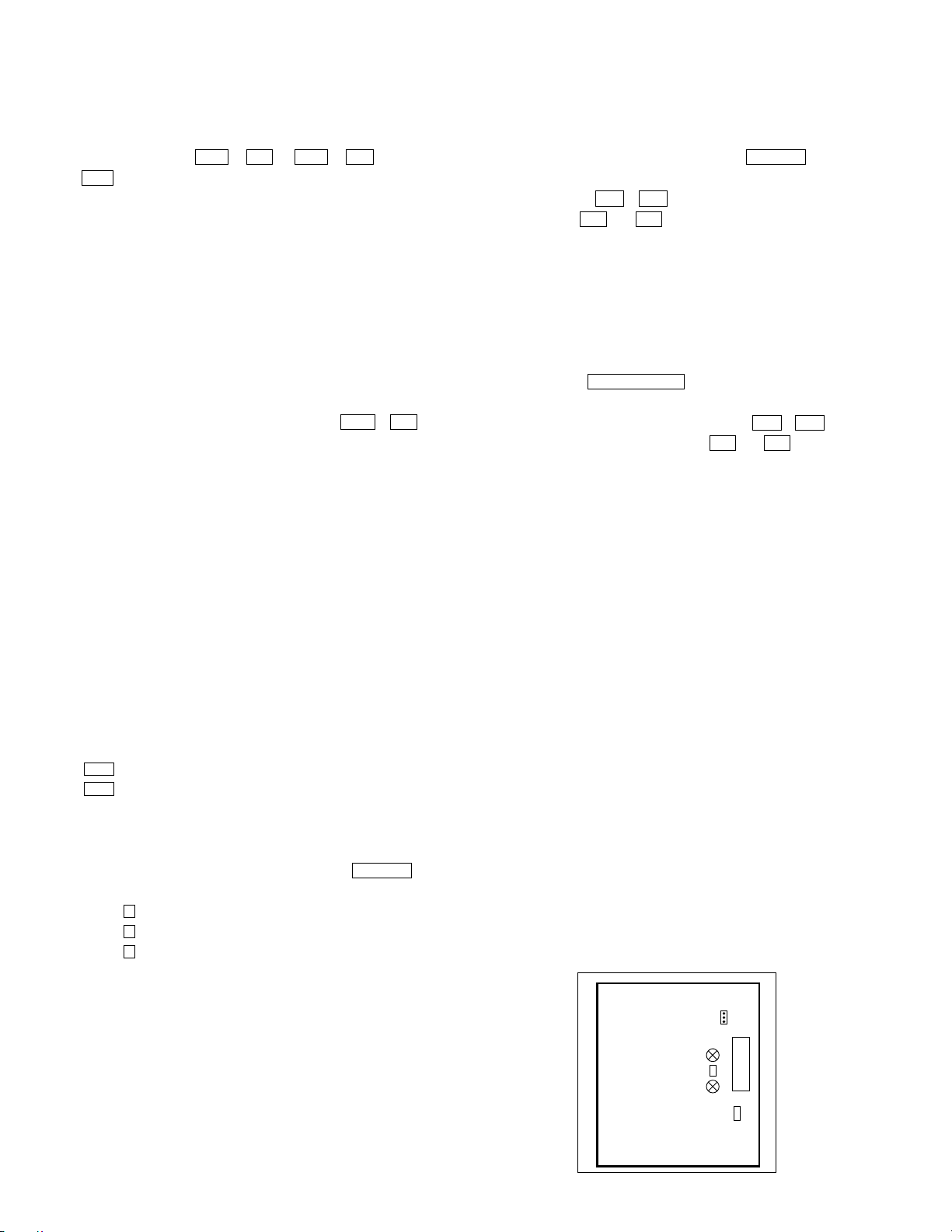
Dolby adjustment
Play the Tape TCC-130 and adjust so that -6dBm (388mV) is
achieved at test points for Lch/Rch, Fwd/Rev. For each
channel, common difference within 2dB (310mV - 488mV)
∗ Make an end of adjustment prior to shipment from the factory.
VR1
VR2
R
CN2
front
and
CN5
L
R
G
L
TEST MODE / ADJUSTMENT

A B C D E
1
2
3
4
5
6
7
9
43
21
S1
D1
IC1
X16-1250-00 (J74-1225-02)
X16-1250-00 (J74-1225-02)
R2
R1
R3
C1
16
D2
CN1
X16-1250-00
IC Q
address
16A
DOLBY
R
L
DOLBYL
DOLBYR
W10
W11
W6
C15
VR1
C6
W2
W5
W3
W4
W7
W9
W1
W8
VR2
C16
C5
1
5
10
1
13
CN4
CN3
CN2
X87-3040-00 (J74-1226-12)
C29
C28
C30
C25C26
C31
C32
C9
C12
C11
C4
R4
C3
C1
C2
R5
R2R1
R3
C20
W12
W14
R11
W13
C23
R8
C7
R13
R7
C22
C14
R6
C8
C24
R12
R10
C17
C13
R9
C21
EB
1
40
31
30
21
20
11
10
IC1
Q1
X87-3040-00
IC Q
address
13D
14C
PC BOARD
(COMPONENT SIDE VIEW)
(FOIL SIDE VIEW)
(FOIL SIDE VIEW)
Refer to the schematic diagram for the values of resistors and capacitors.
 Loading...