

Page 1

DMX9720XDS
MONITOR WITH RECEIVER
Quick Start Guide
MONITEUR AVEC RÉCEPTEUR
Guide de démarrage rapide
MONITOR MIT RECEIVER
Schnellstartanleitung
MONITOR MET ONTVANGER
Snelstartgids
MONITOR CON RICEVITORE
Guida rapida all’avvio
MONITOR CON RECEPTOR
Guía de inicio rápido
MONITOR COM RECETOR
Guia de Início Rápido
МОНИТОР С РЕСИВЕРОМ
Краткое руководство по
началу работы
• Updated information (the latest Instruction Manual, system updates, new functions, etc.) is available from
• Des informations actualisées (le dernier mode d'emploi, les mises à jour du système, les nouvelles fonctions, etc.) sont disponibles sur le site
• Aktualisierte Informationen (die aktuelle Bedienungsanleitung, Systemupdates, neue Funktionen usw.) finden Sie unter
• Bijgewerkte informatie (de meest recente instructiehandleiding, systeemupdates, nieuwe functies, enz.) is beschikbaar op
• Informazioni aggiornate (il Manuale di istruzioni più recente, aggiornamenti di sistema, nuove funzioni, ecc.) sono disponibili da
• La información actualizada (el Manual de instrucciones más actualizado, actualizaciones del sistema, nuevas funciones, etc.) está disponible desde
• Estão disponíveis informações atualizadas (o Manual de Instruções mais recente, atualizações de sistema, novas funções, etc.) em
• Обновленная информация (последняя инструкция по эксплуатации, системные обновления, новые фу
<https://www.kenwood.com/cs/ce/>
нкции и др.) доступна по адресу
Hi-Res Audio logo and Hi-Res
Audio Wireless logo are used
under license from Japan Audio
Society.
B5K-0762-00 (E)© 2020 JVCKENWOOD Corporation
Page 2

Important Notice on Software
EULA
Ñ Software License on This Product
The software embedded in this product
comprises a number of independent software
components, each of which is copyrighted by
JVCKENWOOD Corporation or by a third party.
This product uses software components that
are based on an End-User License Agreement
(hereinafter called “EULA”) stipulated by
JVCKENWOOD Corporation and by third parties.
The EULA dictates the availability of the source
codes of free-software components as a
prerequisite to distributing them in executable
form under the terms of the GNU General
Public License or the Lesser General Public
License (hereinafter called “GPL/LGPL”). To get
information about the software components
that are subject to the terms of the GPL/LGPL,
please visit the following Website:
Website URL https://www2.jvckenwood.com/gpl/
Queries concerning the contents of the source
code or the like will not be accepted.
Please note that software components based
on a EULA that is not subject to the terms of the
GPL/LGPL or those that have been developed
or created by JVCKENWOOD Corporation will
be excluded from the scope of source code
disclosure.
Because licenses to use software components
distributed under the GPL/LGPL are offered to
the customers for free of charge, no warranty is
granted to the customers, whether explicitly or
implicitly, to the extent of the applicable laws.
Unless otherwise stipulated by the applicable
laws or agreed upon in writing, the copyright
holders or those who are entitled to modify
and redistribute the software components are
not held responsible for any and all damages
resulting from their use or from inability to use
them. For more information about the terms of
use of the software components, required items
of compliance and so on, please refer to the
GPL/LGPL.
Customers wishing themselves to use a software
component that is subject to the GPL/LGPL
embedded in this product are encouraged to
read the terms of the corresponding license
before use. Because each individual license
is prescribed by a third party other than
JVCKENWOOD Corporation, the original (English)
of the license is presented.
2
Ñ Software License Agreement
JVCKENWOOD Corporation (hereinafter called
“Licensor”) holds either the copyright to the
embedded software or the right to sublicense
it. This agreement establishes the conditions
under which the customer uses this “Licensed
Software.”
The customer shall agree to the terms of this
license agreement before proceeding to use
Licensed Software.
This agreement is deemed to have taken effect
when the customer (hereinafter called “User”)
has used a product implementation of Licensed
Software.
The Licensed Software may contain software
Licensor has been licensed to use by third
parties directly or indirectly. Some third parties
may have terms of use prescribed for their
customers, apart from this Software License
Agreement. This agreement does not apply to
such software. Be sure to consult “Important
Notice on Software” as presented separately.
Article 1 (General)
Licensor grants to User a non-exclusive,
non-assignable right of use Licensed Software
within the country where the User purchases
the Product (hereinafter the "Country") (except
for the exception provided for in Paragraph 1,
Article 3).
Article 2 (Right of Use)
1.
The rise of use granted under this agreement
is the right to use Licensed Software in this
product.
2.
User may not duplicate, copy, modify, add to,
translate or otherwise alter, or loan licensed
Software and the associated literature in
whole or in part.
3.
Use of Licensed Software is limited to a
private extent , and Licensed Software may
not be distributed, licensed or sublicensed
for any purposes whatsoever, including
commercial use.
4.
User shall use Licensed Software as per the
instruction manual or instructions given in the
help file and may not use or duplicate data in
violations of the regulations of the Copyright
Law or other governing laws by using
Licensed Software in whole or in part.
Page 3

Article 3 (Terms of License)
1.
In assigning this product, User may not retain
the original copy of the embedded Licensed
Software (including associated literature,
updates and upgrades) and any duplicates
and associated literature with regard to
the license to use Licensed Software. User
may transfer Licensed Software only to the
condition of binding the assignee to abide by
the terms of this Software License Agreement.
2.
User may not reverse-engineer, disassemble,
decompile or otherwise analyze the source
code of Licensed Software.
Article 4 (Rights to Licensed Software)
All rights to Licensed Software and the
associated literature, including copyrights, shall
reside with Licensor or
the original right holder who has granted the
Right of Use and right to sublicense to Licensor
(hereinafter referred to as “Original Right
Holder”), and User does not have any rights
other than Right of Use granted hereunder
with regard to Licensed Software and the
associated literature.
Article 5 (Exemption Granted to Licensor)
1.
Licensor and Original Right Holder do not
assume any responsibility for damages
caused to User or third parties resulting from
the exercise by User of the license granted
hereunder, unless otherwise provided by any
law to the contrary.
2.
Licensor does not warrant Licensed Software
to be merchantable, compatible and fit for
specific purposes.
Article 6 (Responsibility for Third Parties)
If disputes over the infringement of third
parties’ intellectual property rights, such as
copyrights and patent rights, arise out of the
use of Licensed Software by User, User shall
resolve these disputes at User’s own expenses
while keep Licensor and Original Right Holder
harmless.
Article 7 (Secrecy Obligation)
User shall keep confidential Licensed Software
provided hereunder, information contained in
the associated literature or the like and those
provisions of this agreement not yet in public
knowledge and may not disclose or leak these
to third parties without prior written consent
from Licensor.
Article 8 (Cancellation of the Agreement)
Licensor reserves the right to cancel this
agreement forthwith and claim compensation
from User for the damages caused by such
cancellation when User:
(1)
Breaches any of the provisions of this
agreement, or
(2)
Has received a petition for seizure, provisional
seizure, provisional disposition or any other
kind of compulsory execution.
Article 9 (Destruction of Licensed Software)
If this agreement is terminated under the
provision of the foregoing paragraph, User
shall destroy Licensed Software, along with all
associated literature and its duplicates, within
two (2) weeks from the date of termination.
Article 10 (Copyright Protection)
1.
Copyrights and all other intellectual property
rights relating to Licensed Software shall
reside with Licensor and Original Right Holder
and in no circumstances with User.
2.
User shall abide by the laws relating to
copyrights and intellectual property rights in
using Licensed Software.
Article 11 (Export Control)
1.
Licensed Software and the associated
literature or the like may not be exported
to places outside the Country (including
transmission outside the Country over the
Internet or the like).
2.
User agrees that Licensed Software is subject
to export controls imposed by the Country
and the United States of America.
3.
User agrees to comply with all the
international and domestic laws that apply
to this software (U.S. Export Administration
Regulations and regulations established by
the U.S., the Country and their governmental
agencies regarding usage by end users and
export destinations).
Article 12 (Miscellaneous)
1.
Even if this agreement is invalidated in part by
law, all other provisions shall remain in effect.
2.
Licensor and User shall consult each other in
good faith to resolve any matters not provided
for in this agreement or questions arising from
the interpretation of this agreement.
3.
Licensor and User agree that this agreement
is governed by the law of Japan and that all
disputes involving claims and obligations that
may arise out of this agreement will be settled
by arbitration at the Tokyo District Court as the
court of first instance.
3
Page 4
Before Use
Contents
Before Use 4
About the Quick start guide ......................................4
Precautions ......................................................................4
How to read this manual .............................................5
Touch screen operations .............................................5
Note for specifications .................................................5
Basic Operations 6
Functions of the Buttons on the Front Panel .......6
Turning on the Unit .......................................................6
Calendar/clock settings ...............................................6
HOME screen ...................................................................7
Popup menu ....................................................................7
Radio ..................................................................................8
Digital Radio ....................................................................8
USB/iPod/iPhone ...........................................................9
Bluetooth Control 10
Register the Bluetooth device ................................10
Using the Hands-Free Unit ......................................11
Connection/Installation 12
Before Installation ......................................................12
Installing the unit ........................................................14
Before Use
About the Quick start guide
• This Quick Start Guide describes basic functions of this
unit. For functions not described in this Guide, refer to
the Instruction Manual on the following website:
https://manual.kenwood.com/edition/im406/
Precautions
# WARNINGS
Ñ To prevent injury or fire, take the
following precautions:
• To prevent a short circuit, never put or leave
any metallic objects (such as coins or metallic
tools) inside the unit.
• Do not watch or fix your eyes on the unit’s
display when you are driving for any extended
period.
• If you experience problems during installation,
consult your KENWOOD dealer.
Ñ Precautions on using this unit
• When you purchase optional accessories,
check with your KENWOOD dealer to make
sure that they work with your model and in
your area.
• You can select a language to display menus,
audio file tags, etc. See System Setup (P.56)
in the Instruction Manual.
• The Radio Data System feature won’t work in
areas where the service is not supported by
any broadcasting station.
Ñ Protecting the monitor
• To protect the monitor from damage, do not
operate the monitor using a ball point pen or
similar tool with a sharp tip.
Ñ Cleaning the unit
• If the faceplate of this unit is stained, wipe it
with a dry soft cloth such as a silicon cloth.
If the faceplate is stained badly, wipe it with
a cloth moistened with neutral cleaner, then
wipe it again with a clean soft dry cloth.
NOTE
• Applying spray cleaner directly to the unit
may damage its mechanical parts. Wiping the
faceplate with a hard cloth or using a volatile
liquid such as thinner or alcohol may scratch the
surface or erase the screened print.
• The Instruction manual is subject to change for
modification of specifications and so forth. Be sure to
download the latest edition of the Instruction manual
for reference.
4
Page 5
Before Use
Ñ Acquiring GPS signal
The first time you turn on this unit, you must
wait while the system acquires satellite signals
for the first time. This process could take up
to several minutes. Make sure your vehicle
is outdoors in an open area away from tall
buildings and trees for fastest acquisition.
After the system acquires satellites for the first
time, it will acquire satellites quickly each time
thereafter.
Ñ About GLONASS
This unit uses Global Navigation Satellite System
(GLONASS) in addition to GPS.
Combining GPS and GLONASS can refine
positioning accuracy than using GPS only.
Ñ Caution for Smartphone Users
Simultaneously running multiple applications
on your smartphone while screen sharing places
heavy demand on the microprocessor of the
phone, potentially affecting communication and
performance.
For best results while pairing with your
KENWOOD receiver, please be sure to close any
unused applications.
How to read this manual
• The screens and panels shown in this
manual are examples used to provide a clear
explanation of operations.
For this reason, they may be different from
the actual screens or panels, or some display
patterns may be different from the actual ones.
• Display language: English is used for the
purpose of explanation. You can select a
display language from the [SETUP] menu.
See System Setup (P.56) in the Instruction
Manual.
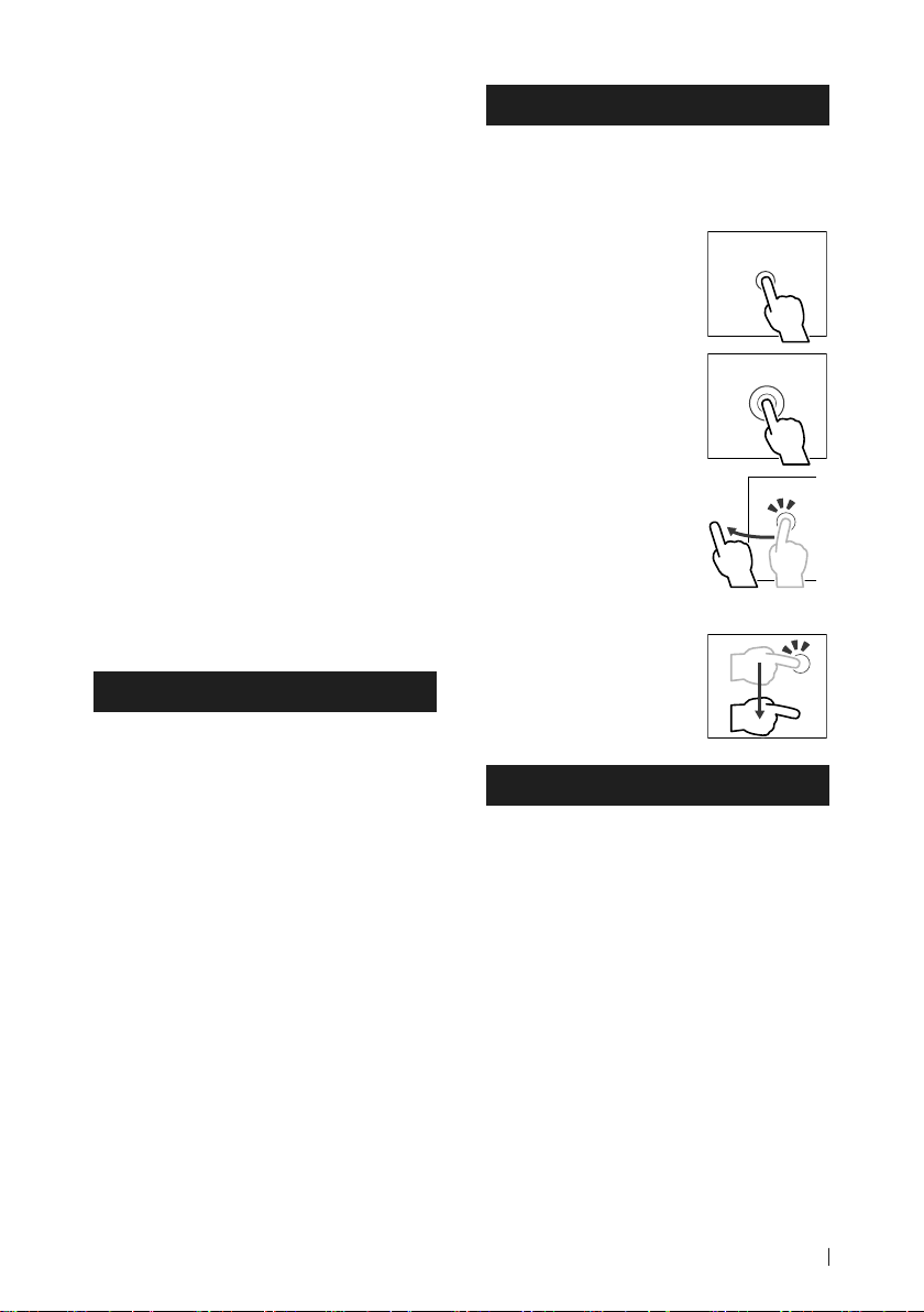
Touch screen operations
To perform operations on the screen, you need
to touch, touch and hold, flick or swipe to
select an item, display a setting menu screen
or change pages.
● Touch
Touch the screen gently to
select an item on the screen.
● Touch and hold
Touch the screen and keep
your finger in place until
the display changes or a
message is displayed.
● Flick
Slide your finger quickly
to the left or right on the
screen to change the page.
You can scroll a list screen
by flicking up/down on the
screen.
● Swipe
Slide your finger up or down
on the screen to scroll the
screen.
Note for specifications
■ Bluetooth section
Frequency
: 2.402 – 2.480 GHz
RF Output Power (E.I.R.P.)
: +4 dBm (MAX), Power Class2
■ General
Operating Voltage
: 12 V DC car battery
Speaker Impedance
: 4 – 8 Ω
5English
Page 6
Basic Operations
Basic Operations
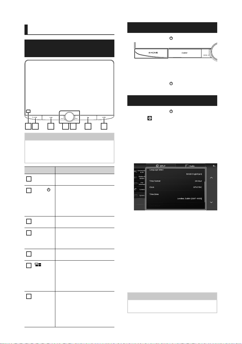
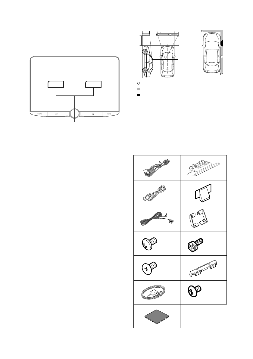
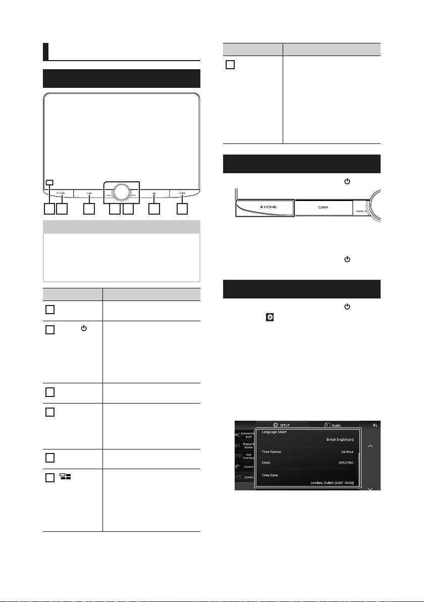
Functions of the Buttons on the Front Panel
2 3 6 71 4 5
NOTE
• The panels shown in this manual are examples
used to provide a clear explanation of operations.
For this reason, they may be different from the
actual panels.
Name Motion
Remote
1
Sensor
HOME/[ ]
2
CAM • Switches view camera display
3
MENU/ATT • Displays the popup menu
4
Volume
5
knob
6
VOICE • Switches the voice recognition
7
6
• Receives the remote control
signal.
• Displays the HOME screen
(P. 7).
• Pressing for 1 second turns the
power off.
• When the power is off, turns the
power on.
on/off.
screen.
• Pressing for 1 second switches
attenuation of the volume on/off.
• Adjusts the volume.
• Displays the APP (Apple
CarPlay/Android Auto/Wireless
Mirroring) screen.
• While the APP screen is
displayed, switches to the
control screen of current source.
function on/off.
• When neither Apple CarPlay,
Android Auto, nor a Bluetooth
Hands-Free phone is connected,
pressing and holding displays
Bluetooth pairing waiting dialog.
Turning on the Unit
Press the [HOME]/[ ] button.
1
The unit is turned on.
● To turn off the unit:
Press the [HOME]/[ ] button for 1
1
second.
Calendar/clock settings
Press the [HOME]/[ ] button.
1
Touch [ ].
2
Touch [SETUP].
3
SETUP Menu screen appears.
Touch [System].
4
System setting menu appears.
Set each item as follows.
5
Scroll the page to show hidden items.
■ [Time Format]
Select the time display format.
[12-Hour]/[24-Hour] (Default)
■ [Clock]
[GPS-SYNC] (Default): Synchronizes the
clock time with the GPS.
[Manual]: Set the clock manually.
■ [Time Zone]
Select the time zone.
■ [Clock Adjust]
If you select [Manual] for Clock, adjust the
date and time manually. (P. 7)
NOTE
• Please set the date and time. If they are not set,
some functions may not work.
Page 7
Basic Operations
● Adjust the date and time manually
Touch [Clock Adjust] in the System setting
1
menu.
Adjust the date, then adjust the time.
2
Touch [Set].
3
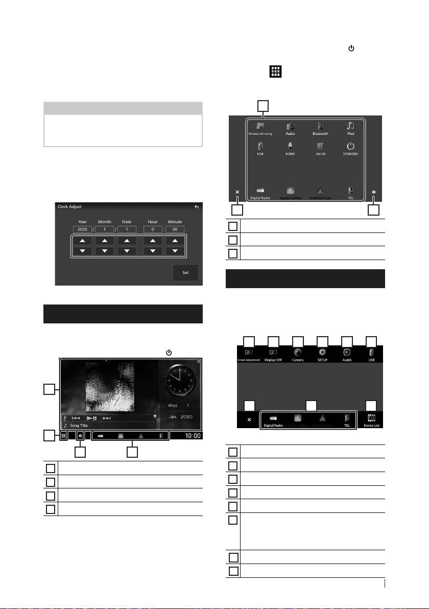
HOME screen
Most functions can be performed from the
HOME screen.
Press the [HOME]/[ ] button.
1
1
2
43
• Widget
1
• Displays the source selection screen.
2
• Displays the SETUP Menu screen.
3
• Short-cut playback source icons
4
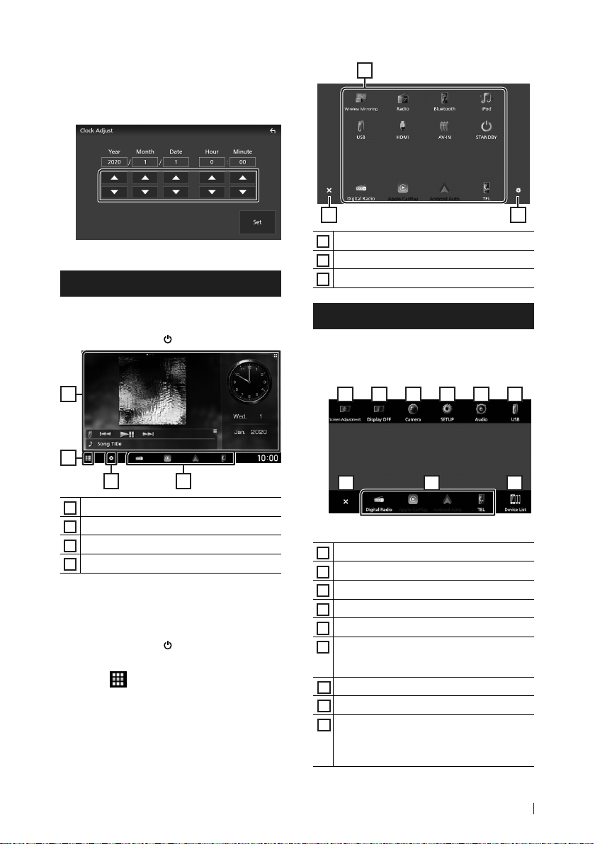
Ñ Source selection screen description
You can display icons of all playback sources
and options on the source selection screen.
Press the [HOME]/[ ] button.
1
HOME screen appears.
Touch [ ].
2
From the screen, you can select the
following sources and functions.
1
2 3
• Changes playback sources.
1
• Returns to the previous screen.
2
• Displays the SETUP Menu screen.
3
Popup menu
Press the [MENU]/[ATT ] button.
1
Popup menu appears.
Touch to display the popup menu.
2
182 3 4 5 6
7
The contents of the menu are as follows.
• Displays the Screen Adjustment screen.
1
• Turns the display off.
2
• Displays the view camera screen.
3
• Displays the SETUP Menu screen.
4
• Displays the Audio screen.
5
• Displays the control screen of current source.
6
Icon feature differs depending on the source.
This icon is for USB source.
• Close the popup menu.
7
• Short-cut source icons:
8
• Displays the Android Auto device list. This icon
9
appears only when Android Auto is connected
and two or more devices can be used as
Android Auto source.
9
7English
Page 8
Basic Operations
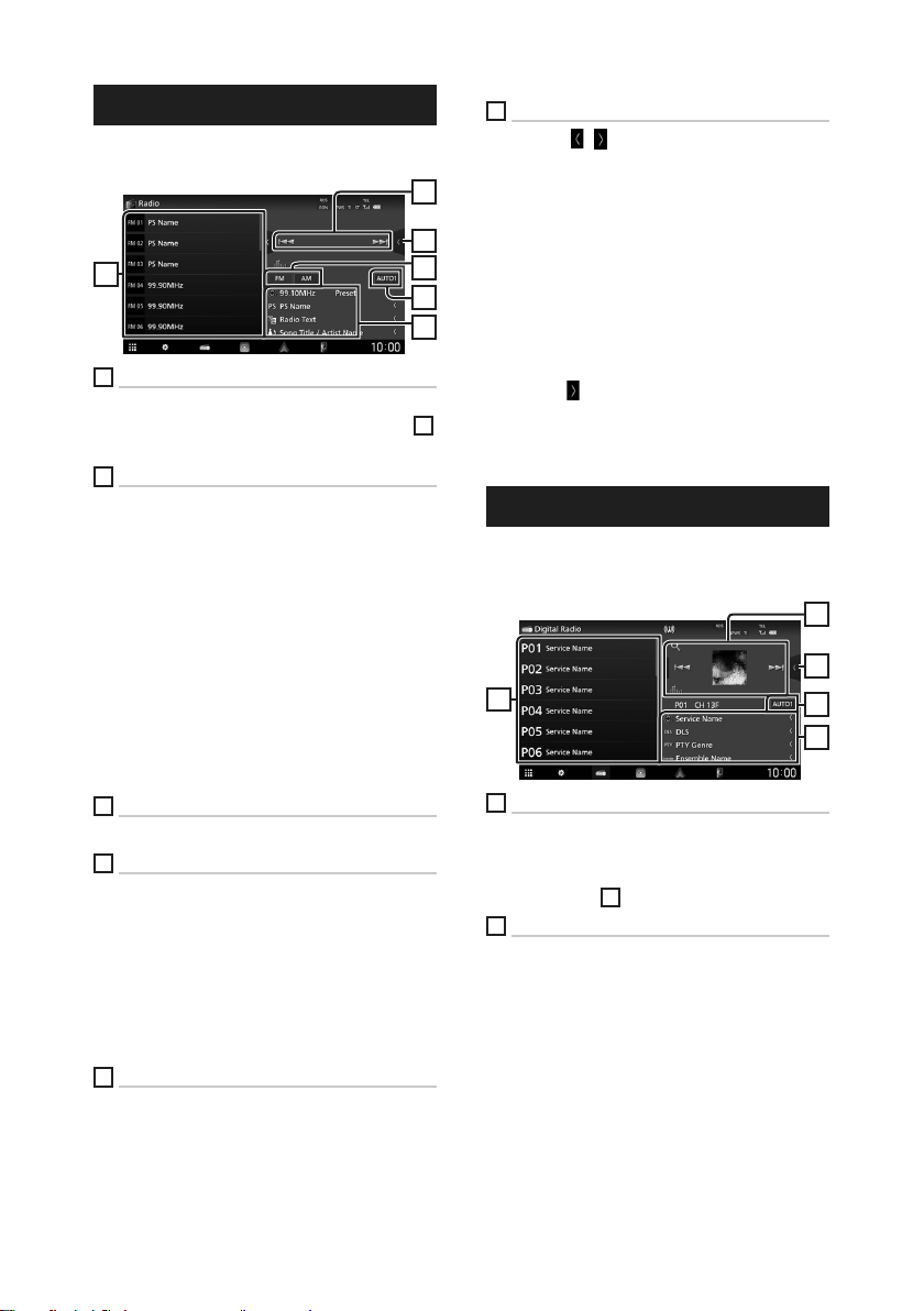
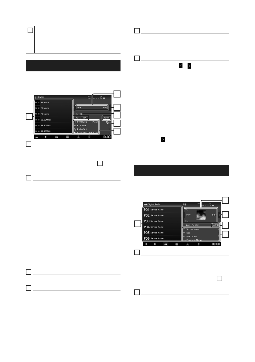
Radio
To listen to the Radio source, touch [Radio]
icon on the source selection screen. (P. 7)
6
1
Operation keys
• [E] [F] : Tunes in a station. The method of
switching frequencies can be changed (see
Seek mode).
2
Function panel
Touch the right side of the screen to display the
function panel. Touch again to close the panel.
• [TI] (FM only) : Selects the traffic information
mode.
• [SETUP](FM only) : Displays the Radio SETUP
screen.
• [AME] : Presets stations automatically.
• [PTY] (FM only) : Searches for a program by
program type.
• [MONO] (FM only) : Selects the Monaural
reception mode.
• [LO.S] (FM only) : Turns the Local Seek
function on or off.
3
Band keys
Switches bands (between FM and AM).
4
Seek mode
Touch to switch seek mode in the following
sequence: [AUTO1], [AUTO2], [MANUAL].
• [AUTO1]: Tunes in a station with good
reception automatically.
• [AUTO2]: Tunes in the memorized stations
one after another.
• [MANUAL]: Switches to the next frequency
manually.
5
Information display
• Displays the information on the current station:
Frequency
Preset#: Preset number
6
Preset list
• Touching [
display size.
1
2
• Recalls the memorized station.
• When touched for 2 seconds, stores the
currently being received station in the
memory.
]/[ ] allows you to change the
3
4
5
4
Ñ Auto memory
You can store stations with good reception in
the memory automatically.
Touch desired band key ([FM]/[AM]).
1
Touch [ ] on the left side of the screen.
2
Touch [AME].
Touch [Yes ].
3
Auto memory starts.
Digital Radio
To listen to Digital Radio source, touch [Digital
Radio] icon on the source selection screen.
(P. 7)
1
2
5
1
Operation keys
• [1] : Displays the Service List screen.
• [E] [F] : Tunes in a ensemble, service, and
component. The seek mode switching can be
changed. (see
2
Function panel
Touch the right side of the screen to display the
function panel. Touch again to close the panel.
• [TI]: Selects the traffic information mode.
• [SETUP]: Displays the Digital Radio SETUP
screen.
• [PTY]: Searches for a program by program
type.
• [DLS]: Display the Dynamic Label Segment
screen.
Seek mode).
3
3
4
8
Page 9
Basic Operations
3
Seek mode
Touch to switch seek modes in the following
sequence: [AUTO1], [AUTO2], [MANUAL].
• [AUTO1]: Tunes in a ensemble with good
reception automatically.
• [AUTO2]: Tunes in the memorized ensemble
one after another.
• [MANUAL]: Switches to the next ensemble
manually.
4
Information display
• Displays the information on the current station:
Service Name
• Touch to switch between the Control and
Information screen.
5
Preset list
• Touching [
display size.
• Recalls the memorized service.
• When touched for 2 seconds, stores the
currently being received service in the
memory.
]/[ ] allows you to change the
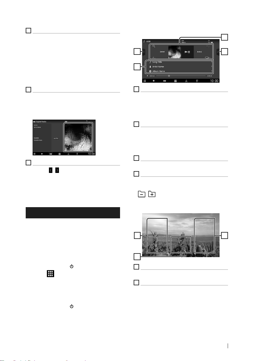
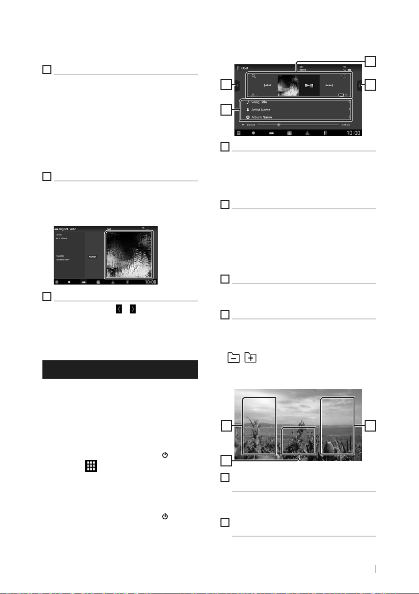
USB/iPod/iPhone
Ñ Basic Operation
2
3
1
Operation keys
• 1] : Searches track/file.
• E] [F] : Searches the previous/next track/
file.
• [DH] : Plays or pauses.
2
Content list
• Touch the left side of the screen to display the
Content list. Touch again to close the list.
• Displays the playing list. When you touch a
track/file name on the list, playback will start.
3
Track information
• Displays the information on the current file.
4
Function panel (USB only)
Touch the right side of the screen to display the
function panel. Touch again to close the panel.
• [
] [ ] : Searches for the previous/next
folder.
Video screen (USB only)
1
4
Ñ Connecting a USB device/iPod/
iPhone
Connect the USB device with the USB
1
cable. (P. 21)
Connect the iPod/iPhone using the KCAiP103. (P. 22)
Press the [HOME]/[ ] button.
2
Touch [ ].
3
Touch [USB] or [iPod]. (P. 7)
4
Ñ Disconnect the USB device/iPod/
iPhone
Press the [HOME]/[ ] button.
1
Touch a source other than [USB].
2
Detach the USB device/iPod/iPhone.
3
6
5
File search area (Video file only)
Touch to search for the next/previous file.
6
Key display area (Video file only)
Touch to display the control screen.
55
9English
Page 10
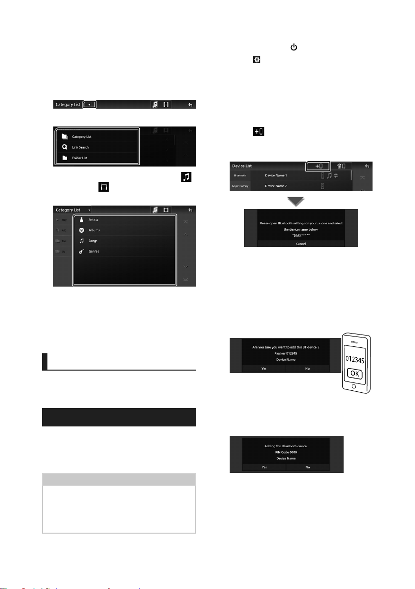
Bluetooth Control
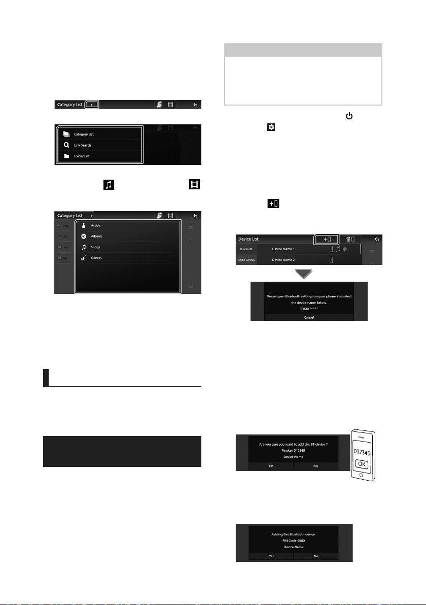
Ñ Search Operation
You can search music or video files by the
following operations.
Touch [1].
1
Touch [S].
2
Select a list type.
3
Select whether you search audio files
4
or video files
Touch the desired category.
5
The list corresponding to your selection
appears.
Touch to select the desired item in the
6
list. Repeat this step until you find the
desired file.
. (USB only)
Press the [HOME]/[ ] button.
1
Touch [ ].
2
Touch [SETUP].
3
SETUP Menu screen appears.
Touch [Connections & AV].
4
Touch [Device List].
5
Select a device type.
6
Touch [ ].
7
Bluetooth pairing waiting dialog
appears.
Search for the unit (”DMX9720XDS”) from
8
your smartphone/cell-phone.
Complete steps 8 to 10 within 30 seconds.
Operate your smartphone/cell-phone
9
according to the displayed messages.
● Confirm the request both on the
smartphone/cell-phone.
Bluetooth Control
Using the Bluetooth function allows you to use
various functions such as listening to the audio
file and making/receiving a call.
Register the Bluetooth device
It is necessary to register the Bluetooth audio
player or smartphone/cell-phone in this unit
before using the Bluetooth function.
You can register up to 10 Bluetooth devices.
NOTE
• Up to 10 Bluetooth devices can be registered. If
an attempt is made to register the 11th Bluetooth
device, the Bluetooth device connected on the
earliest date will be deleted to register the 11th
one.
10
● Input the PIN Code in your
smartphone/cell-phone.
PIN Code is set to “0000” as the default.
Touch [Yes ].
10
Page 11
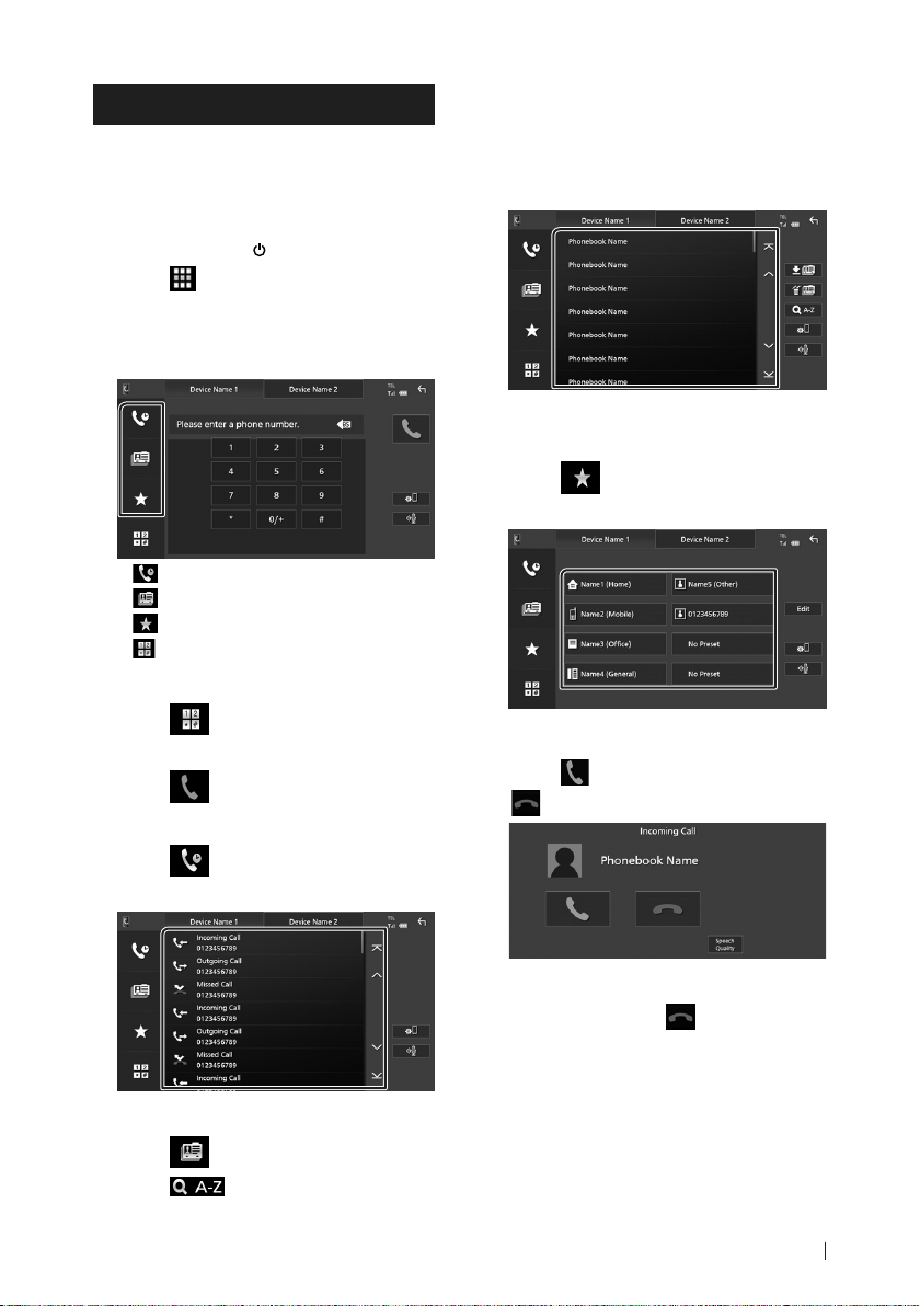
Using the Hands-Free Unit
You can use the telephone function by
connecting the Bluetooth telephone to this
unit.
Ñ Make a call
Press the [HOME]/[ ] button.
1
Touch [ ].
2
Touch [TEL].
3
Hands-Free screen appears.
Select a dialing method.
4
• [ ]: Call using call records
• [
]: Call using the phonebook
• [
]: Call using the preset number
• [
]: Call by entering a phone number
Call by entering a phone number
Bluetooth Control
Select the initial.
3
• Characters with no corresponding name
will not appear.
Select the person you want to call from
4
the list.
Select the phone number from the list.
5
Call using the preset number
Touch [ ].
1
Touch the name or phone number.
2
Touch [ ].
1
Enter a phone number with number keys.
2
Touch [ ].
3
Call using call records
Touch [ ].
1
Select the phone number from the list.
2
Call using the phonebook
Touch [ ].
1
Touch [ ].
2
Ñ Receive a call
Touch [ ] to answer a phone call or
1
[
] to reject an incoming call.
To end call
While talking, touch [ ].
1
11English
Page 12
Connection/Installation
Connection/
Installation
This section is for the professional installer.
For safety’s sake, leave wiring and mounting to
professionals. Consult the car audio dealer.
Before Installation
Before installation of this unit, please note the
following precautions.
# WARNINGS
• If you connect the ignition wire (red) and
the battery wire (yellow) to the car chassis
(ground), you may cause a short circuit, that
in turn may start a fire. Always connect those
wires to the power source running through
the fuse box.
• Do not cut out the fuse from the ignition wire
(red) and the battery wire (yellow). The power
supply must be connected to the wires via
the fuse.
# CAUTION
• Install this unit in the console of your vehicle.
Do not touch the metal part of this unit during
and shortly after the use of the unit. Metal part
such as the heat sink and enclosure become
hot.
NOTE
• Mounting and wiring this product requires
skills and experience. For best safety, leave the
mounting and wiring work to professionals.
• Do not install the unit if it becomes an obstacle
to driver performance.
• Adjust the panel position not to become an
obstacle to driver performance.
• Make sure to ground the unit to a negative 12V
DC power supply.
• Do not install the unit in a spot exposed to
direct sunlight or excessive heat or humidity.
Also avoid places with too much dust or the
possibility of water splashing.
• Do not use your own screws. Use only the
screws provided. If you use the wrong screws,
you could damage the unit.
• If the power is not turned ON (“There is an
error in the speaker wiring. Please check the
connections.” is displayed), the speaker wire
may have a short-circuit or touched the chassis
of the vehicle and the protection function may
have been activated. Therefore, the speaker
wire should be checked.
• If your car’s ignition does not have an ACC
position, connect the ignition wires to a power
source that can be turned on and off with the
ignition key. If you connect the ignition wire to
a power source with a constant voltage supply,
such as with battery wires, the battery may be
drained.
• If the console has a lid, the lid will not be
closed even when the unit is installed correctly.
• If the fuse blows, first make sure the wires are
not touching to cause a short circuit, then
replace the old fuse with one with the same
rating.
• Insulate unconnected wires with vinyl tape or
other similar material. To prevent a short circuit,
do not remove the caps on the ends of the
unconnected wires or the terminals.
• Connect the speaker wires correctly to the
terminals to which they correspond. The unit
may be damaged or fail to work if you share
the ¤ wires or ground them to any metal part
in the car.
• When only two speakers are being connected
to the system, connect the connectors either
to both the front output terminals or to both
the rear output terminals (do not mix front
and rear). For example, if you connect the ¢
connector of the left speaker to a front output
terminal, do not connect the ¤ connector to
a rear output terminal.
• After the unit is installed, check whether the
brake lamps, blinkers, wipers, etc. on the car
are working properly.
• Mount the unit so that the mounting angle is
30° or less.
• This unit has the cooling fan to decrease the
internal temperature. Do not mount the unit
in a place where the cooling fan of the unit is
blocked. Blocking these openings will inhibit
the cooling of the internal temperature and
result in malfunction.
Cooling fan
12
Page 13
Connection/Installation
• Do not press hard on the panel surface when
installing the unit to the vehicle. Otherwise
scars, damage, or failure may result.
• Reception may drop if there are metal objects
near the Bluetooth antenna.
Bluetooth/Wi-Fi antenna unit
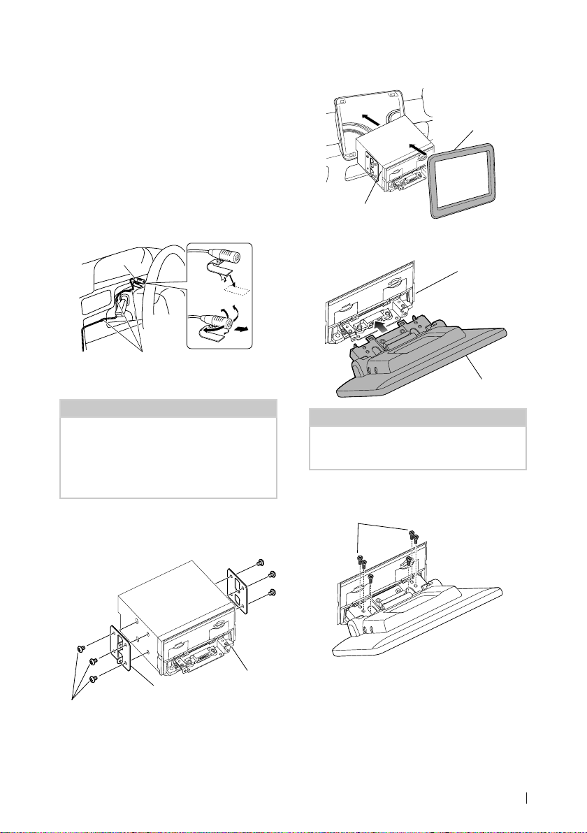
Ñ Installation procedure
1) To prevent a short circuit, remove the key
from the ignition and disconnect the ¤
terminal of the battery.
2) Remove the vehicle parts for installing the
unit and connecting wires to terminal.
3) Make the proper input and output wire
connections for each unit.
4) Determine the height of the display unit and
position of the slider. See Distance between
the display unit and the main unit (P.14).
5) Take Connector B on the wiring harness and
connect it to the speaker connector in your
vehicle.
6) Take Connector A on the wiring harness and
connect it to the external power connector
on your vehicle.
7) Connect the wiring harness connector to the
unit.
8) Install the main unit to the vehicle.
9) Reinstall the vehicle parts.
10) Install the display unit.
11) Reconnect the ¤ terminal of the battery.
12) Perform the Initial Setup.
See Initial SETUP (P.6) in the Instruction
Manual.
● Forward and Lateral Fields of Vision
• To determine driver’s forward and lateral fields
of vision under normal conditions, place a
pole (directly visible from the front or visible
through the car rear-view mirror) as shown.
1
*
1 m 0.7 m 0.9 m
0.3 m
2 m
2
*
0.3 m
2 m
0.3 m
[ ]: Pole (height: 1m, diameter: 0.3m)
[ ]: Field of vision from steering position
[ ]: Exempted area (pole size is subject to
regulation)
• For right hand drive vehicles, standards are
reversed.
*1 The pole must be visible from the driver's position as
direct forward field of vision.
*2 The pole must be directly visible or indirectly visible
through the mirror, etc. from the driver's position.
Ñ Supplied accessories for
installation
1
2
3
(3 m)
4
(M5 x 8 mm)
5
(M5 x 8 mm)
6
(3.5 m)
7
8
x1
9
x1
0
x1
-
x6
=
x6
~
x1
x1
Left/Right
(M5 x 8 mm)
(Ø3 x 6 mm)
(Black)
x1
x2
x1
x6
x1
x2
13English
Page 14

Connection/Installation
4
3
2
1
4
3
2
a
a
d
b
4
3
2
a
d
c
a
4
3
2
1
4
3
2
4
3
2
1
4
3
2
1
4
3
2
1
a
a
a
b
b
d
d
b
c
4
3
2
4
3
2
1
4
3
2
1
a
a
d
d
b
c
4
3
2
1
c
d
c
Installing the unit
Ñ Confirm the installing position of the display unit
● Vehicles cannot be installed
It may be possible to install if it can avoid the following by adjustment for slider position and
display height.
Lever operations are interfered
such as shift lever, wiper lever,
winker lever when install the unit.
● Distance between the display unit and the main unit
Adjust slider position and display height so that it does not interfere with display movement.
Slider
position
Back
position
-10° 0° 45° 1 2 3 4
b
A hazard switch is hidden from a
driver seat.
The display unit hits a panel on the
vehicle.
Display angle Display height
4
3
2
b
1
4
3
2
1
d
4
3
2
1
a 10
-10°
b 38.1 50.9 63.8 76.5
a 26.7
0°
b 34.7 47.7 60.7 73.7
c 5.7 14.4 24.1 33.4
45°
d 55.4 46.3 37.1 27.8
a 30.1
-10°
b 38.1 50.9 63.8 76.5
a 46.7
0°
4
3
2
1
b 34.7 47.7 60.7 73.7
c 25.7 34.9 44.1 53.3
45°
d 55.4 46.3 37.1 27.8
Forward
position
4
3
b
2
b
1
4
3
2
1
d
Unit: mm
Examples
Cluster panel
on the vehicle
14
Slider in back
position
C’
C’ =50mm C’ =50mm
1
C’ =30mm C’ =30mm
4
4
Slider in forward
position
• C'=50mm;
Slider position: Forward position
Display height: Set only "4"
4
1
1
• C'=30mm;
Slider position: Back position
Display height: Set only "4"
4
2
Slider position: Forward position
Display height: Set "2"~"4"
Page 15
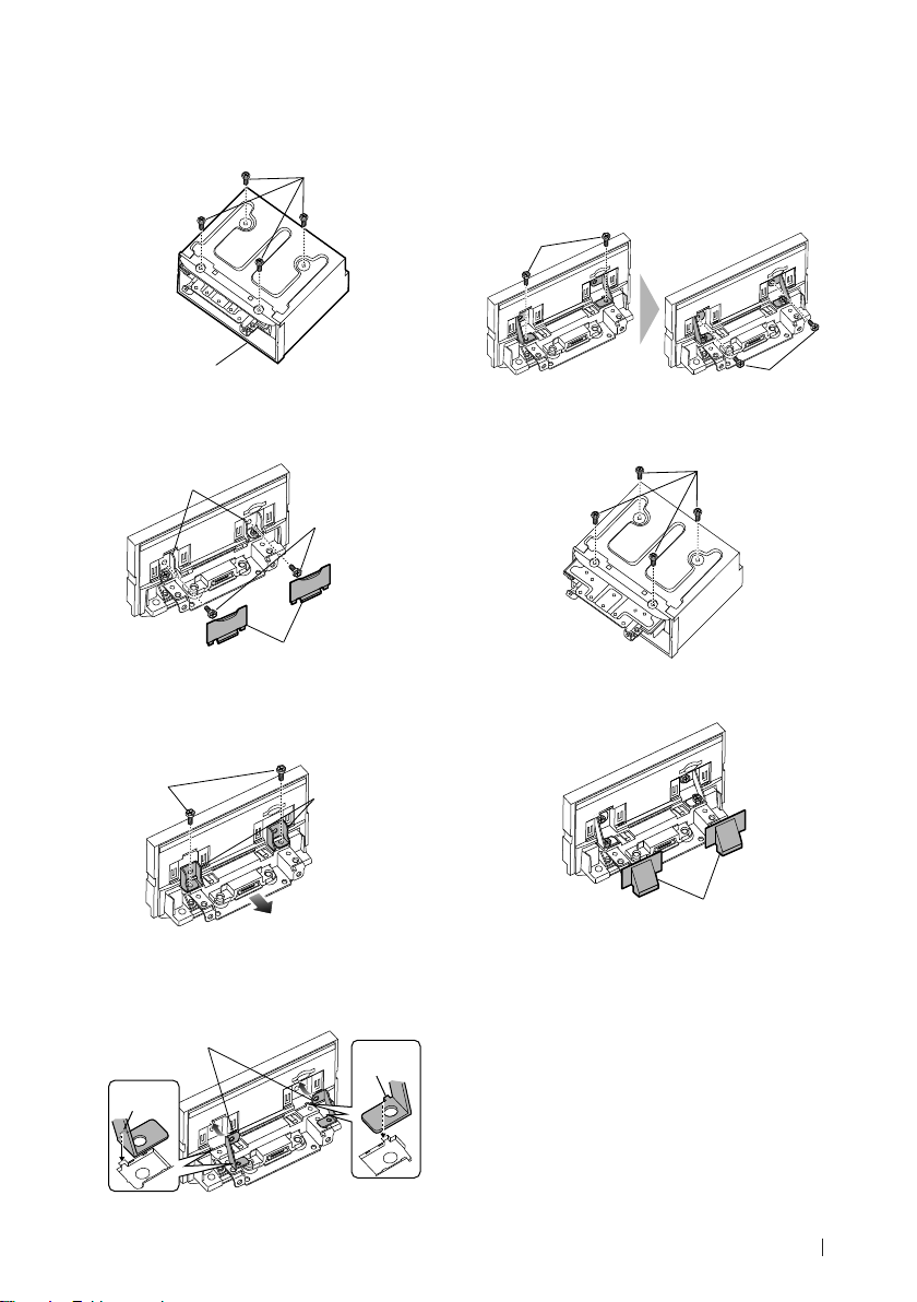
Ñ Positioning the slider in forward
Remove the four screws from the bottom
1
of the main unit.
Screw
Connection/Installation
Fix the bracket for forward position to
5
the slider block with the two hexagon
head screws. Push the slider block until it
stops and then fix the bracket for forward
position to the main unit with the two
hexagon head screws.
Hexagon head
screw
Main unit
Remove the two cover for back position,
2
and then remove the two hexagon head
screws from the bracket for back position.
Bracket for back
position
Hexagon head
screw
Cover for back
position
Pull the slider block forward and remove
3
the two hexagon head screws to remove
the bracket for back position.
Hexagon head
screw
Install the bracket for forward position
4
(accessory 0) each side so that its
projections are aligned with the slots on
the main unit.
0
Projection
Bracket for back
position
Projection
Hexagon
head screw
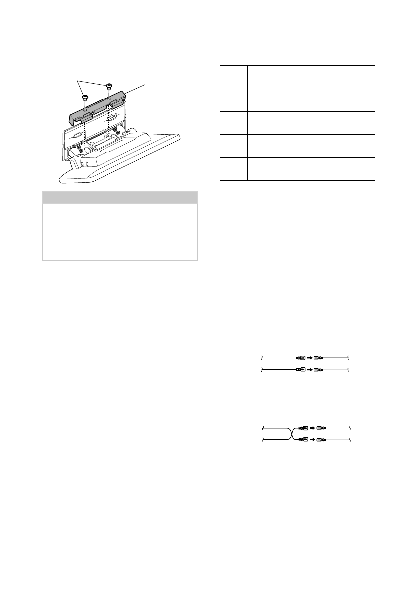
Reinstall the four screws to the bottom of
6
the main unit.
Screw
Install the cover for forward position
7
(accessory 9) to two locations, as shown.
9
15English
Page 16
Connection/Installation
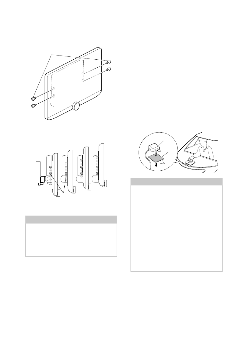
Ñ Adjusting the display height
Remove the four flat head screws from
1
both sides.
Flat head screw
Adjust the display height according to the
2
screw hole position.
Default is "1".
4
3
2
1
Screw hole position
Reinstall the four flat head screws on both
3
sides and fix the display.
NOTE
• Fix with flat head screws correctly. After installing
the display unit (accessory 8) to the main unit,
tilt the display forward until it stops and confirm
that the display unit (accessory 8) does not hit
vehicle parts. If the display unit hits vehicle parts,
adjust the display height again.
Ñ GPS antenna
GPS antenna is installed inside of the car. It
should be installed as horizontally as possible
to allow easy reception of the GPS satellite
signals.
To mount the GPS antenna inside your vehicle:
1) Clean your dashboard or other surface.
2) Remove the separator of the metal plate
(accessory 7).
3) Press the metal plate (accessory 7) down
firmly on your dashboard or other mounting
surface. You can bend the metal plate
(accessory 7) to conform to a curved surface,
if necessary.
4) Remove the separator of the GPS antenna
(accessory 6), and stick the antenna to the
metal plate (accessory 7).
6
7
NOTE
• Use the supplied GPS antenna. Using the GPS
antenna other than the supplied one may cause a
drop in positioning accuracy.
• Depending on the type of car, reception of the
GPS satellite signals might not be possible with
an inside installation.
• Please install this GPS antenna in an area away
from any antennas that are used with CB radios or
satellite televisions.
• The GPS antenna should be installed at a position
that is spaced at least 12 inch (30 cm) from
smartphone/cell-phone or other transmitting
antennas. Signals from the GPS satellite may be
interfered with by these types of communication.
• Painting the GPS antenna with (metallic) paint
may cause a drop in performance.
16
Page 17
Ñ Microphone unit
1) Check the installation position of the
microphone (accessory 3).
2) Clean the installation surface.
3) Remove the separator of the microphone
(accessory 3), and stick the microphone to
the place shown below.
4) Wire the microphone cable up to the unit
with it secured at several positions using tape
or other desired method.
5) Adjust the direction of the microphone
(accessory 3) to the driver.
3
Fix a cable with a commercial item of tape.
Connection/Installation
Reinstall the removed parts such as a
5
panel on the vehicle.
Panel on the
vehicle
Main unit
Install the display unit (accessory 8) to
6
the main unit.
Main unit
Ñ Installing the main unit
NOTE
• Determine the slider position before installing the
main unit. (P. 15) The slider position cannot be
changed after installing to the vehicle.
• Make sure that the unit is installed securely in
place. If the unit is unstable, it may malfunction
(eg, the sound may skip).
Remove parts that interfere with
1
installing such as a panel on the vehicle.
Install the car bracket to the main unit.
2
Main unit
Car bracket
4 or 5
Connect the wiring harness wires and
3
peripheral equipment.
Install the main unit to the vehicle.
4
8
NOTE
• If the display unit hits a panel on the vehicle,
adjust the display height by referring to
Adjusting the display height (P.16).
Fix the display unit with six hexagon head
7
screws (accessory -).
-
17English
Page 18
Connection/Installation
Attach the protective cover (accessory =)
8
to coupling part, and then fix it with two
binding head screws (accessory ~).
~
=
NOTE
• If the protective cover (accessory =) is not
attached, this unit will not turn on. Even if the
unit is turned on, the power may be turned off
halfway.
Be sure to attach the protective cover (accessory
=).
Raise the display manually.
9
Ñ Wiring harness (Accessory 1)
connector function guide
Pin Color and function
A-4 Yellow Battery
A-5 Blue/White
A-6 Orange/White Dimmer
A-7 Red Ignition (ACC)
A-8 Black Earth (Ground) Connection
B-1/B-2 Purple (+) / Purple/Black (–) Rear Right
B-3/B-4 Gray (+) / Gray/Black (–) Front Right
B-5/B-6 White (+) / White/Black (–) Front Left
B-7/B-8 Green (+) / Green/Black (–) Rear Left
*Speaker Impedance: 4-8 Ω
[1] [2]: Blue/White wire is provided two wires, [1] and [2].
Blue/White wire total output ([1] + [2]):
12 V = 350 mA
#WARNING for Connecting the ISO
Connector
The pin arrangement for the ISO connectors depends
on the type of vehicle you drive. Make sure to make
the proper connections to prevent damage to the
unit. The default connection for the wiring harness is
described in (1) below. If the ISO connector pins are set
as described in (2), make the connection as illustrated.
Please be sure to reconnect the cable as shown (2)
below to install this unit to the Volkswagen vehicles etc.
(1): Default setting
The red (A-7 pin) of the vehicle’s ISO connector is linked
with the ignition, and the yellow (A-4 pin) is connected
to the constant power supply.
Red (Ignition cable)
Yellow (Battery cable) Yellow (A-4 pin)
(2)
The red (A-7 pin) of the vehicle’s ISO connector is
connected to the constant power supply, and the
yellow (A-4 pin) is linked to the ignition.
Red (Ignition cable)
Yellow (Battery cable) Yellow (A-4 pin)
[2]
Power Control
Red (A-7 pin)
Unit Vehicle
Red (A-7 pin)
Unit Vehicle
18
Page 19
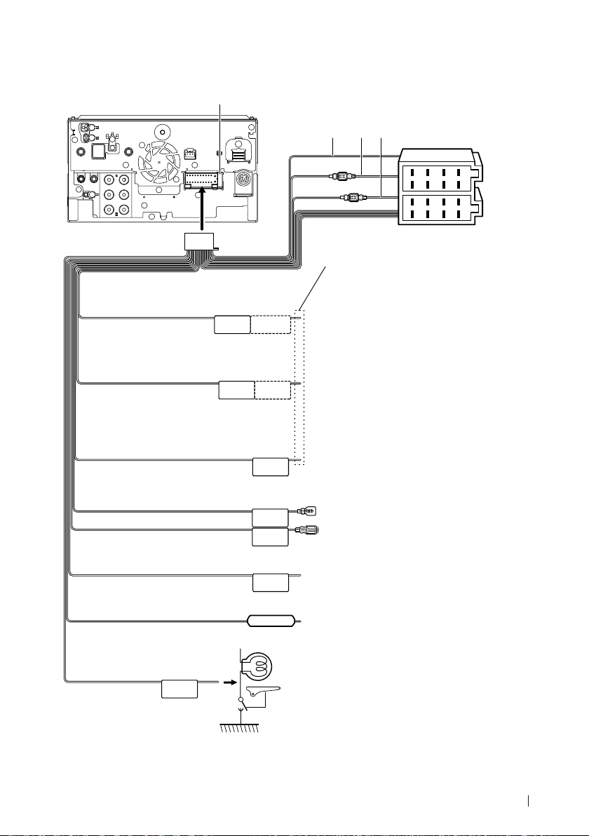
Ñ Connecting wires to terminals
Fuse (15A)
A: Black (Ground wire)
B: Yellow (Battery wire)
C: Red (Ignition wire)
A B C
Connection/Installation
Connector A
Accessory 1
Light Blue/Yellow
(Steering remote control wire)
Blue/White
[1]
(Power control/Antenna control wire)
Brown
(Mute control wire)
Green/White
Green/Red
Purple/White
(Reverse sensor wire) (2 m)
Pink
(Speed Pulse Input) (2m)
REMOTE CONT
P. CONT
STEERING WHEEL
REMOTE INPUT
ANT CONT
MUTE
CAM–
CAM+
REVERSE
S SENS
8
1234567
8
1234567
Connector B
If no connections are made, do not let the cable
come out from the tab.
To steering remote
To use the steering wheel remote control feature,
you need an exclusive remote adapter (not supplied)
matched to your car.
Connect either to the power control terminal when
using the optional power amplifier, or to the power
terminal for the booster amplifier of the film-type or
short pole type antenna.
Connect to the terminal that is grounded when either
the telephone rings or during conversation.
To CMOS-3xx series (optional accessory) camera
control terminal
Connect to vehicle’s reverse lamp harness when using
the optional rear view camera.
Connect to the vehicle’s speed pulse harness.
Do not cut the "S SENS" tag or failure may result.
Light Green
(Parking sensor wire) (2 m)
PRK SW
Connect to the vehicle’s parking brake detection switch
harness.
For best safety, be sure to connect
the parking sensor.
[1] [2]: Blue/White wire is provided two wires, [1] and [2]. Blue/White wire total output ([1] + [2]): 12 V = 350 mA
19English
Page 20
Connection/Installation
Ñ 3-way speaker system setup
Subwoofer Preout
Mid Range Preout
Tweeter Preout
When connecting to an external amplifier,
connect its ground wire to the car’s chassis to
avoid damaging the unit.
Preout
RCA Cable
(Sold separately)
Power amplifier
(optional
accessory)
Input
White
+
White/Black
Gray
+
Gray/Black
Green
+
Green/Black
Purple
+
Purple/Black
NOTE
• For speaker system setup, see 3-way speaker
system setup (P.57) in the Instruction Manual.
• For speaker setup and crossover setup, see
Speaker / X’over setup (P.58) in the
Instruction Manual.
• For how to connect speaker wires to terminals
other than speaker terminals and Preout
terminals, see Connecting the system and
external components (P.20) and Connecting
wires to terminals (P.19).
Speaker
To mid range left
speaker
To mid range right
speaker
To tweeter left speaker
To tweeter right
speaker
Speaker impedance: 4-8 Ω
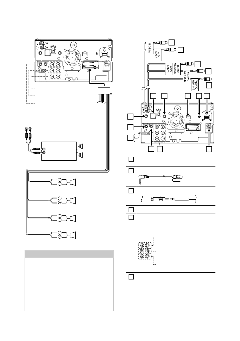
Ñ Connecting the system and
external components
16
15
911 10 8 7
1
2
3
4
5
Connect to vehicle’s steering remote harness.
1
Contact your KENWOOD dealer for details.
Accessory 3: Bluetooth Microphone
2
FM/AM antenna input
3
AV Audio output (ø3.5 mini jack)
4
When connecting to an external amplifier,
5
connect its ground wire to the car’s chassis to
avoid damaging the unit.
Rear Audio Preout
(Left; White, Right; Red)
Front Audio Preout
(Left; White, Right; Red)
Subwoofer Preout
(Left; White, Right; Red)
External I/F
6
Maximum power supply current :
12 V = 500 mA
14
13
12
6
20
Page 21
Connection/Installation
HDMI input
7
Use HDMI cable KCA-HD100 (optional
accessory).
When you connect the cable to HDMI terminal,
remove the fixture. After connecting the cable,
put the fixture again.
Fixture
HDMI connector
Digital Radio antenna CX-DAB1 (Optional
8
accessory)
!
Use of a CX-DAB1(optional accessory) as a
Digital Radio antenna is recommended.
When using a commercially available Digital
Radio antenna, the diameter of the SMB
connector must be Φ6.5 mm or less.
Φ 6.5 mm (maximum)
Dashboard camera interface
9
Connect a Dashboard Camera DRV-N520
(optional accessory). ( P.23)
AV Audio input (ø3.5 mini jack)
10
Accessory 6: GPS Antenna
11
Use the supplied GPS antenna. Using the GPS
antenna other than the supplied one may
cause a drop in positioning accuracy.
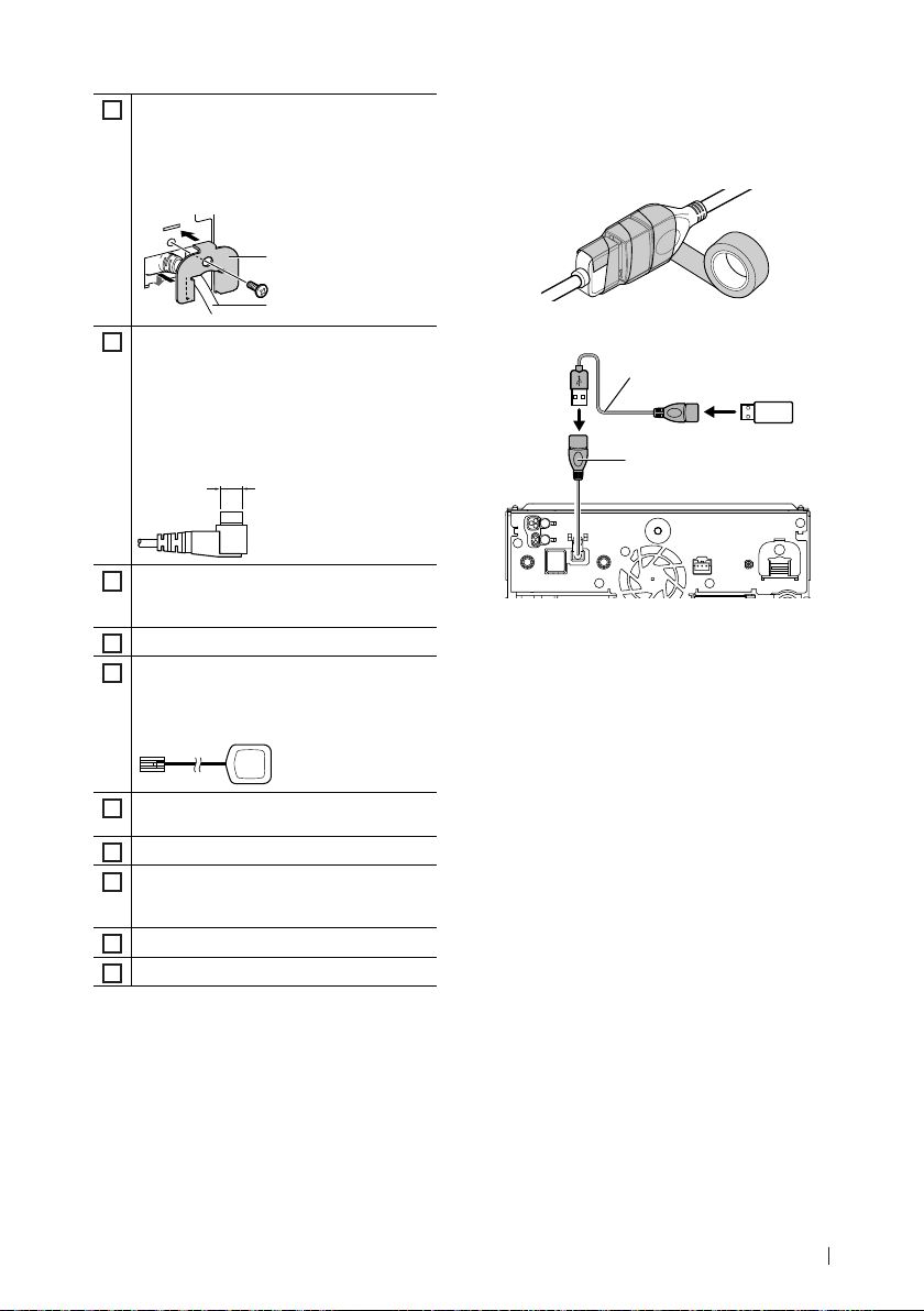
Ñ Securing the USB extension cable
Secure the USB extension cable with insulating
tape or the like so that its connectors are not
disconnected.
Ñ Connecting a USB device
Accessory 2 (1 m)
USB terminal
[1]
USB maximum power supply current :
DC 5 V = 1.5 A
[2]
Sold separately
[3]
See Securing the USB extension cable
(P. 21).
[3]
USB device
[1]
[2]
3rd view camera input (Yellow). See To set up
12
the camera assignment settings (P.23).
Rear view camera input (Yellow) *
13
Front view camera/Dashboard camera
14
input (Yellow).*2 See To set up the camera
assignment settings (P.23).
Video output (Yellow)
15
Video input (Yellow)
16
1
*1 Connect an HD camera to Rear view camera
input terminal to use HD video.
*2 Connect an HD camera to Front view camera/
Dashboard camera input terminal to use HD
video.
21English
Page 22
Connection/Installation
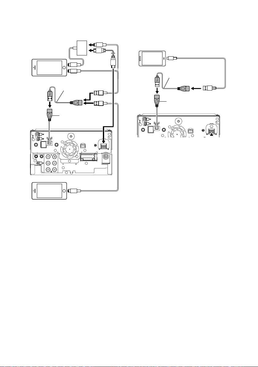
Ñ Connecting an iPod/iPhone
Lightning Digital AV
[2]
Adapter
iPod/iPhone
[2]
Accessory 2 (1 m)
USB terminal
iPhone (with Apple CarPlay)
[1]
USB maximum power supply current :
DC 5 V = 1.5 A
[2]
Sold separately
[3]
Optional accessory
[4]
See Securing the USB extension cable
(P. 21).
KCA-iP103 (0.8 m)
KCA-HD100
(1.8 m)
KCA-iP103 (0.8 m)
[4]
[1]
[2]
KCA-iP103 (0.8 m)
[3]
[3]
[3]
[3]
smartphone
Android smartphone
(with Android Auto)
[1]
USB maximum power supply current :
DC 5 V = 1.5 A
[2]
Sold separately
[3]
See Securing the USB extension cable
(P. 21).
[2]
USB cable
Accessory 2 (1 m)
USB terminal
[1]
[2]
[3]
Ñ Connecting an Android
22
Page 23
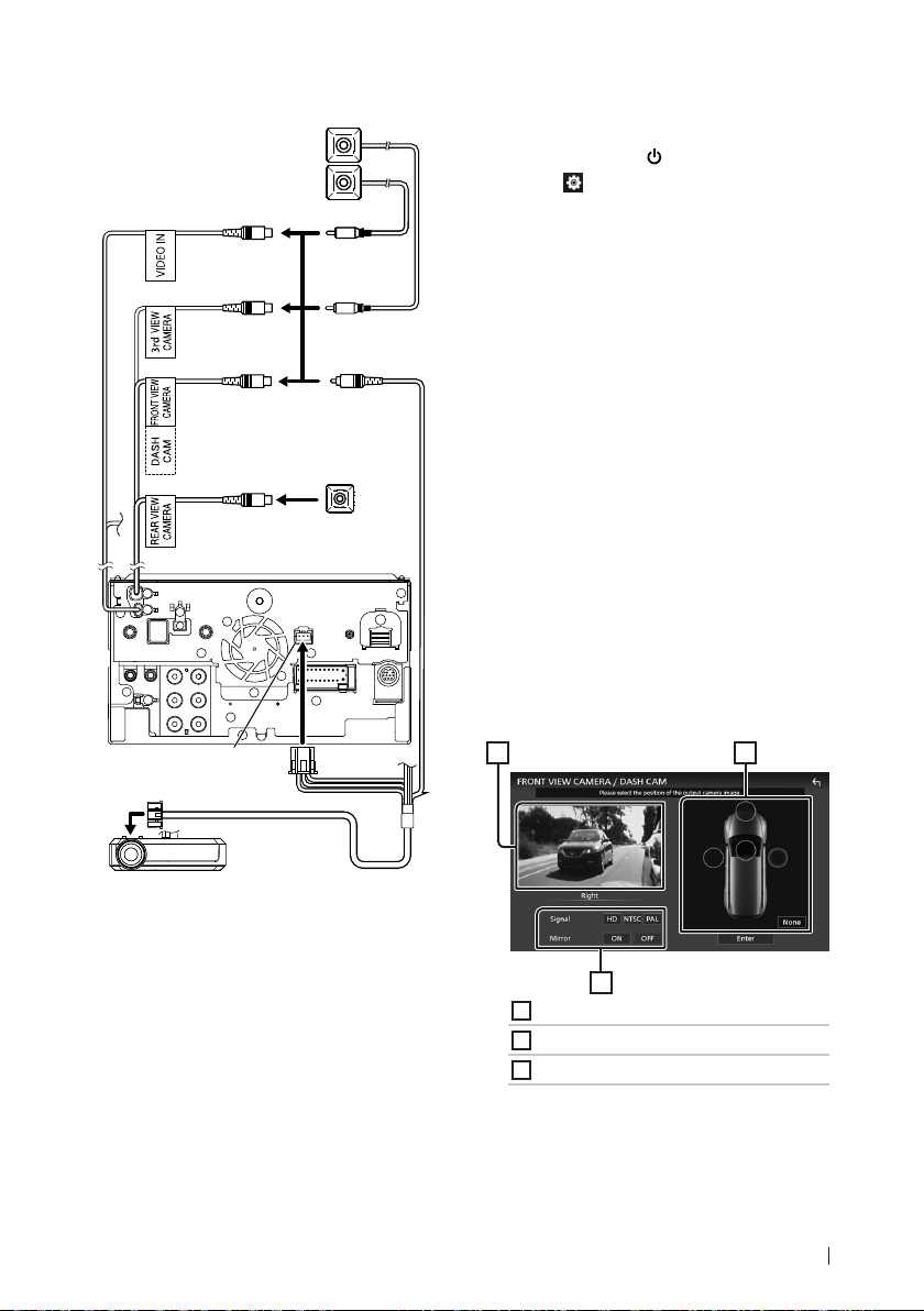
Connection/Installation
Ñ Connecting the camera
Left side view camera and
Right side view camera
Front view camera
Video input
(Yellow)
3rd view camera
input (Yellow)
Front view camera/
Dashboard camera
input (Yellow)
Rear view camera
input (Yellow)
Dashboard camera interface
[4] [6]
Rear view camera
Ñ To set up the camera assignment
settings
[2]
[3]
[4] [5]
Press the [HOME]/[ ] button.
1
Touch [ ].
2
Touch [SETUP].
3
SETUP Menu screen appears.
Touch [Camera].
4
Camera setting menu appears.
Touch [Camera Assignment Settings].
5
Select the item to set up.
6
■ [REAR VIEW CAMERA]
Set the camera assignment from view
camera connected to Rear view camera
input terminal.
■ [FRONT VIEW CAMERA / DASH CAM]
Set the camera assignment from view
camera connected to Front view camera/
Dashboard camera input terminal.
■ [3rd VIEW CAMERA]
Set the camera assignment from view
camera connected to 3rd view camera input
terminal.
■ [VIDEO IN]
Set the camera assignment from view
camera connected to Video input terminal.
Select the view camera to set up.
7
1 2
DRV-N520
[1]
Optional accessory
[2]
Sold separately
[3]
Up to 3 cameras of Dashboard camera, Front
[1]
view camera, Left side view camera and Right
side view camera can be connected. (P. 23)
[4]
CMOS-3xx series (optional accessory) or
commercially available camera.
[5]
For HD video, an HD camera is also used as
Rear view camera.
[6]
For HD video, an HD camera is also used as
Front view camera.
3
1
[Picture from view camera]
2
[Camera position]
3
[Picture quality settings]
Touch [Enter].
8
23English
Page 24

Avant l'utilisation
Table des matières
Avant l'utilisation 24
À propos du guide de démarrage rapide ..........24
Précautions ...................................................................24
Comment lire ce manuel ..........................................25
Fonctionnement tactile ............................................25
Note pour les spécifications....................................25
Utilisation de base 26
Fonctions des boutons en façade .........................26
Mise en marche de l'appareil .................................. 26
Réglages du calendrier/horloge............................26
Écran HOME ..................................................................27
Menu contextuel ......................................................... 27
Radio ............................................................................... 28
Radio numérique ........................................................ 28
USB/iPod/iPhone ........................................................29
Utilisation du Bluetooth 30
Enregistrez le périphérique Bluetooth ................30
Utilisation du module mains-libres ......................31
Connexion/Installation 32
Avant l'installation ......................................................32
Installation de l'appareil ........................................... 34
Avant l'utilisation
À propos du guide de démarrage rapide
• Ce Guide de démarrage rapide décrit les fonctions de
base de cet appareil. Pour les fonctions non décrites
dans ce guide, reportez-vous au manuel d'instructions
disponible sur le site Web suivant :
https://manual.kenwood.com/edition/im406/
• Le mode d'emploi est susceptible d'être modifié
suite aux changements pouvant être apportés aux
spécifications etc. Téléchargez impérativement
la dernière édition du mode d'emploi aux fins de
référence.
Précautions
#AVERTISSEMENTS
Ñ Pour éviter toute blessure ou
incendie, prenez les précautions
suivantes:
• Pour éviter un court-circuit, ne mettez ni ne
laissez jamais d'objets métalliques (comme des
pièces de monnaie ou des outils métalliques) à
l'intérieur de l'appareil.
• Ne regardez pas ni ne fixez votre regard
sur l'affichage de l'appareil trop longtemps
pendant la conduite.
• Si vous rencontrez des problèmes pendant
l'installation, consultez votre revendeur
KENWOOD.
Ñ Précautions d'utilisation de
l'appareil
• Lorsque vous achetez des accessoires en
option, vérifiez auprès de votre revendeur
KENWOOD qu'ils fonctionneront avec votre
modèle et dans votre région.
• Vous avez le choix de la langue dans laquelle
s'affichent les menus, les balises des fichiers
audio, etc. Voir Configuration système
(p.56) dans le mode d'emploi.
• La fonction Radio Data System ne fonctionne
pas dans les zones où le service n'est pris en
charge par aucune station de radiodiffusion.
Ñ Protection du moniteur
• Ne touchez pas le moniteur avec un stylo à
bille ou tout autre outil pointu. Cela pourrait
l'endommager.
Ñ Nettoyage de l'appareil
• Si la façade de l'appareil est tâchée, essuyez-la
avec un chiffon doux et sec comme un chiffon
en silicone. Si la façade est très sale, essuyezla avec un chiffon humidifié d'un produit de
nettoyage neutre, puis essuyez-la à nouveau
avec un chiffon doux et sec propre.
REMARQUE
• La pulvérisation directe de produit de nettoyage
sur l'appareil risque d'endommager les pièces
mécaniques. Si vous nettoyez la façade avec un
chiffon trop rugueux ou un liquide volatil, comme
un solvant ou de l'alcool, vous risquez d'en rayer
la surface ou d'effacer les caractères sérigraphiés.
24
Page 25
Avant l'utilisation
Ñ Réception du signal GPS
Lors de la première mise sous tension de
l'appareil, vous devez attendre que le système
acquière les signaux satellite pour la première
fois. Ce processus peut durer quelques minutes.
Pour une acquisition rapide des signaux, veillez à
ce que votre véhicule se trouve à l'extérieur, sur
une zone ouverte éloignée des bâtiments hauts
et des arbres.
Après la première acquisition des signaux
satellite, le système pourra acquérir les signaux
satellite plus rapidement par la suite.
Ñ À propos de GLONASS
Cet appareil utilise le Système mondial de
navigation par satellite (GLONASS) en plus du
GPS.
La combinaison du GPS et du GLONASS permet
d'affiner la précision de positionnement par
rapport au GPS seul.
Ñ Avertissement pour les utilisateurs
de smartphones
L’exécution en simultané de plusieurs
applications sur votre smartphone, en écran
partagé, sollicite tout particulièrement son
microprocesseur, d’où une altération potentielle
des performances et de la qualité des
communications.
Afin d'obtenir des résultats optimaux lors de
l'appariement de votre récepteur KENWOOD,
assurez-vous de fermer toutes les applications
inutilisées.
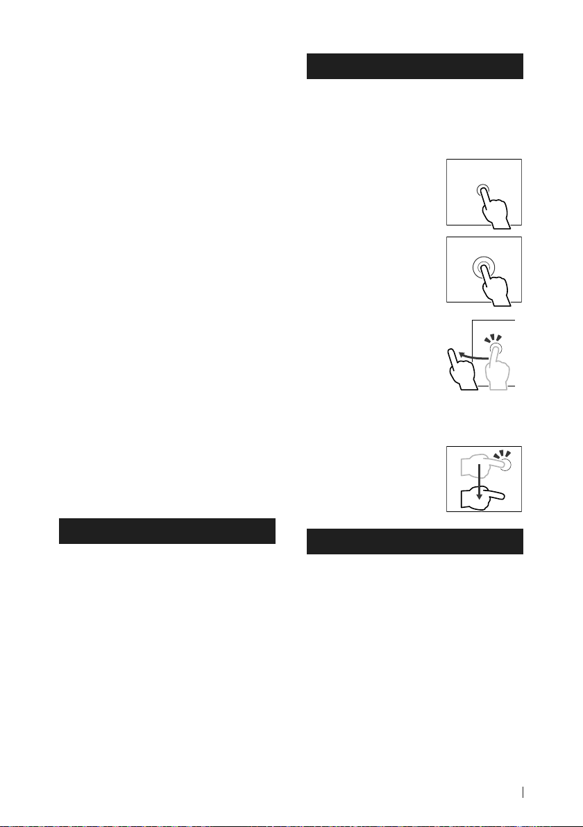
Fonctionnement tactile
Pour réaliser des opérations sur l'écran, vous
devez toucher, toucher longuement, feuilleter
ou défiler pour sélectionner un élément,
afficher l'écran de menu de réglage ou
changer les pages.
● Toucher
Touchez légèrement l'écran
pour sélectionner un
élément sur l'écran.
● Toucher longuement
Touchez l'écran et gardez
votre doigt sur l'écran
jusqu'à ce que l'affichage
change ou qu'un message
soit affiché.
● Feuilleter
Faites glisser votre doigt
rapidement vers la gauche
ou vers la droite sur l'écran
pour changer de page.
Vous pouvez faire défiler
un écran de liste en faisant
glisser votre doigt vers le
haut/bas sur l'écran.
● Défiler
Faites glisser votre doigt vers
le haut ou le bas pour faire
défiler l'écran.
Comment lire ce manuel
• Les écrans et façades illustrés dans le présent
manuel sont des exemples destinés à fournir
une explication plus claire des opérations.
C'est pourquoi il est possible qu'ils soient
différents des écrans ou de la façade de
l'appareil, ou que certaines séquences
d'affichage soient différentes de celles utilisées.
• Langue d'affichage: L'anglais est utilisé
dans un but explicatif. Vous pouvez choisir la
langue d'affichage à partir du menu [SETUP].
Voir Configuration système (p.56) dans le
mode d'emploi.
Note pour les spécifications
■ Section Bluetooth
Fréquence
: 2,402 – 2,480 GHz
Puissance de sortie RF (E.I.R.P.)
: +4 dBm (MAX), classe de puissance 2
■ Général
Tension de fonctionnement
: batterie de voiture 12 V CC
Impédance d'enceinte
: 4 – 8 Ω
25Français
Page 26
Utilisation de base
Utilisation de base
Fonctions des boutons en façade
2 3 6 71 4 5
REMARQUE
• Les écrans illustrés dans le présent manuel sont
des exemples destinés à fournir une explication
plus claire des opérations. Pour cette raison,
il peut arriver qu'ils soient différents de ceux
rencontrés dans la réalité.
26
Désignation
Capteur de
1
télécommande
HOME/[ ]
2
CAM • Active/désactive l'affichage de
3
MENU/ATT • Affiche l'écran du menu
4
Bouton du
5
volume
6
Mouvement
• Reçoit le signal de la
télécommande.
• Affiche l'écran d'ACCUEIL
(p.27).
• Appuyez pendant 1 seconde
pour éteindre l'appareil.
• Quand l'appareil est éteint,
permet de le mettre en
marche.
la caméra de vue.
contextuel.
• Appuyez pendant 1 seconde
pour commuter l'atténuation
du volume sur marche/arrêt.
• Règle le volume.
• Affiche l'écran APP (Apple
CarPlay/Android Auto/
Miroitage sans fil).
• Lorsque l'écran de
l'application s'affiche, l'écran
passe à l'écran de contrôle de
la source actuelle.
Désignation
VOICE • Active ou désactive la fonction
7
Mouvement
de reconnaissance vocale.
• Lorsque ni Apple CarPlay, ni
Android Auto, ni un téléphone
mains libres Bluetooth
n'est connecté, le fait de
maintenir enfoncé le bouton
permet d'afficher la boîte de
dialogue de mise en attente
d'appariement Bluetooth.
Mise en marche de l'appareil
Appuyez sur le bouton [HOME]/[ ].
1
L'appareil se met en marche.
● Pour éteindre l'appareil:
Appuyez sur le bouton [HOME]/[ ]
1
pendant 1 seconde.
Réglages du calendrier/horloge
Appuyez sur le bouton [HOME]/[ ].
1
Touchez [ ].
2
Touchez [SETUP].
3
L'écran de menu de configuration
s'affiche.
Touchez [System].
4
Le menu des paramètres du système
s'affiche.
Réglez chaque option comme suit.
5
Faites défiler la page pour afficher les
éléments cachés.
■ [Time Format]
Sélectionnez le format d'affichage de l'heure.
[12-Hour]/[24-Hour] (valeur par défaut)
■ [Clock]
[GPS-SYNC ](Par défaut): Synchronise l'heure
de l'horloge avec le GPS.
[Manual]: Réglez l'horloge manuellement.
Page 27
Utilisation de base
■ [Time Zone]
Sélectionnez le fuseau horaire.
■ [Clock Adjust]
Si vous sélectionnez [Manual] pour l'horloge,
réglez la date et l'heure manuellement. (p.27)
REMARQUE
• Veuillez régler la date et l'heure. Si elles ne sont
pas réglées, certaines fonctions peuvent ne pas
fonctionner.
● Réglez la date et l'heure manuellement
Touchez [Clock Adjust] dans le menu de
1
configuration du système.
Réglez la date puis l'heure.
2
Touchez [Set].
3
Écran HOME
La plupart des fonctions sont accessibles
depuis l'écran ACCUEIL.
Appuyez sur le bouton [HOME]/[ ].
1
Appuyez sur le bouton [HOME]/[ ].
1
L'écran d'ACCUEIL apparaît.
Touchez [ ].
2
Depuis cet écran, vous pouvez sélectionner
les sources et fonctions suivantes.
1
2 3
• Change les sources de lecture.
1
• Revient à l'écran précédent.
2
• Affiche l'écran du menu CONFIGURATION.
3
Menu contextuel
Appuyez sur le bouton [MENU]/[ATT ].
1
Le menu contextuel s'affiche.
Appuyez pour afficher le menu
2
contextuel.
182 3 4 5 6
1
2
43
• Widget (élément graphique)
1
• Affiche l'écran de sélection de la source.
2
• Affiche l'écran du menu CONFIGURATION.
3
• Icônes de raccourci de source de lecture
4
Ñ Description de l'écran de sélection
de source
Vous pouvez afficher les icônes de toutes les
sources de lecture et les options sur l'écran de
sélection de source.
7
Le menu contient les options suivantes.
• Affiche l'écran de réglage de l'écran.
1
• Éteint l'affichage.
2
• Affiche l'écran de la caméra de vue.
3
• Affiche l'écran du menu CONFIGURATION.
4
• Affiche l'écran audio.
5
• Affiche l'écran de contrôle de la source
6
en cours. Les fonctionnalités attachées au
pictogramme varient selon les sources. Cette
icône est pour la source USB.
• Fermez le menu contextuel.
7
• Icônes de sources de raccourcis :
8
9
27Français
Page 28
Utilisation de base
• Affiche la liste des périphériques Android
9
Auto. Cette icône n'apparaît que si Android
Auto est connecté et que deux périphériques
ou plus peuvent être utilisés comme source
Android Auto.
Radio
Pour écouter la source radio, appuyez sur
l'icône [Radio] sur l'écran de sélection de la
source. (p.27)
6
1
Touches de commande
• [E] [F] : Syntoniser sur une station. Il
est possible de changer la méthode de
commutation des fréquences (voir
de recherche).
2
Panneau de fonction
Appuyez sur le côté droit de l'écran pour afficher
le panneau de fonction. Appuyez de nouveau
pour fermer le panneau.
• [TI] (FM uniquement) : Sélectionne le mode
infos-trafic.
• [SETUP] (FM uniquement) : Affiche l'écran de
CONFIGURATION de la radio.
• [AME] : Prédéfinit automatiquement les stations.
• [PTY] (FM uniquement) : Recherche un
programme par type de programme.
• [MONO] (FM uniquement) : Sélectionne le
mode de réception monaurale.
• [LO.S] (FM uniquement) : Active ou désactive la
fonction de recherche locale.
3
Touches de bande
Change les bandes (entre FM et AM).
4
Mode de recherche
Touchez pour changer de mode de recherche
dans l'ordre suivant : [AUTO1], [AUTO2],
[MANUAL].
• [AUTO1] : Syntonise automatiquement sur une
station offrant une bonne réception.
• [AUTO2] : Syntonise les stations en mémoire
les unes après les autres.
• [MANUAL] : Commute sur la fréquence
suivante manuellement.
28
4
Mode
5
Affichage des informations
• Affiche les informations concernant la station
en cours : Fréquence
Préréglage # : Numéro de préréglage
6
Liste des présélections
• Un simple appui sur [
changer la taille de l'écran.
• Rappelle la station mémorisée.
• En le touchant pendant 2 secondes, il
1
mémorise la station en cours de réception.
]/[ ] vous permet de
Ñ Mémoire automatique
2
3
4
5
Vous pouvez enregistrer automatiquement les
stations offrant une bonne réception dans la
mémoire.
Touchez la touche de la bande de votre
1
choix ([FM]/[AM]).
Touchez [ ] sur le côté gauche de l'écran.
2
Touchez [AME].
Appuyez sur [Yes ].
3
La mémorisation automatique se lance.
Radio numérique
Pour écouter une source radio numérique,
appuyez sur l'icône [Digital Radio] sur l'écran
de sélection de la source. (p.27)
1
2
5
1
Touches de commande
• [1] : Affiche l'écran de liste des services.
• [E] [F] : Syntonisation sur un ensemble, un
service et un composant. Le mode recherche
de commutation peut être modifié. (voir
Mode de recherche).
2
Panneau de fonction
Appuyez sur le côté droit de l'écran pour afficher
le panneau de fonction. Appuyez de nouveau
pour fermer le panneau.
• [TI]: Sélectionne le mode infos-trafic.
• [ SETUP] : Affiche l'écran de CONFIGURATION
de la radio numérique.
• [PTY] : Recherche un programme par type de
programme.
3
4
3
Page 29
Utilisation de base
• [DLS]: Afficher l'écran de segment d'Étiquette
Dynamique.
3
Mode de recherche
Touchez pour changer de mode de recherche
dans l'ordre suivant : [AUTO1], [AUTO2],
[MANUAL].
• [AUTO1] : Syntonise automatiquement sur un
ensemble offrant une bonne réception.
• [AUTO2] : Syntonise les ensembles en
mémoire les uns après les autres.
• [MANUAL] : Commute sur l'ensemble suivant
manuellement.
4
Affichage des informations
• Affiche les informations concernant la station
en cours : Nom du service
• Touchez pour sélectionner successivement
l'écran de contrôle ou d'information.
5
Liste des présélections
• Un simple appui sur [
changer la taille de l'écran.
• Rappelle le service mémorisé.
• En le touchant pendant 2 secondes, il
mémorise le service en cours de réception.
]/[ ] vous permet de
USB/iPod/iPhone
Ñ Connexion d'un périphérique USB/
iPod/iPhone
Connectez le périphérique USB avec le
1
câble USB. (p.41)
Connectez l'iPod/iPhone à l'aide du KCAiP103. (p.42)
Appuyez sur le bouton [HOME]/[ ].
2
Touchez [ ].
3
Appuyez sur [USB] ou [iPod]. (p.27)
4
Ñ Déconnexion d'un périphérique
USB/iPod/iPhone
Appuyez sur le bouton [HOME]/[ ].
1
Touchez une source autre que [USB].
2
Détachez le périphérique USB/iPod/
3
iPhone.
Ñ Utilisation de base
1
2
3
1
Touches d'opération
• 1] : Fait une recherche de piste/fichier.
• E] [F] : Recherche la piste/fichier
précédent/suivant.
• [DH] : Lit ou met en pause.
2
Liste des contenus
• Touchez le côté gauche de l'écran pour afficher
la Liste de contenu. Appuyez de nouveau pour
fermer la liste.
• Affiche la liste de lecture. Lorsque vous
appuyez sur un nom de fichier/piste dans la
liste, la lecture démarre.
3
Informations sur la piste
• Affiche les informations concernant le fichier
en cours.
4
Panneau de fonctions (USB uniquement)
Appuyez sur le côté droit de l'écran pour afficher
le panneau de fonction. Appuyez de nouveau
pour fermer le panneau.
• [
] [ ] : Recherche le dossier précédent/
suivant.
Écran vidéo (USB uniquement)
6
5
Zone de recherche des fichiers (fichier
vidéo uniquement)
Touchez pour faire une recherche du fichier
suivant/précédent.
6
Zone d'affichage des touches (fichier
vidéo uniquement)
Touchez pour afficher l'écran de contrôle.
4
55
29Français
Page 30
Utilisation du Bluetooth
Ñ Recherche
Vous pouvez rechercher des fichiers de
musique ou vidéo en procédant comme suit.
Touchez [1].
1
Touchez [S].
2
Choisissez un type de liste.
3
Sélectionnez si vous recherchez des
4
fichiers audio ou des fichiers vidéo
. (USB uniquement)
Touchez la catégorie de votre choix.
5
La liste correspondant à votre choix
s'affiche.
Touchez pour sélectionner l'élément de
6
votre choix dans la liste. Répétez cette
étape jusqu'à ce que vous ayez trouvé le
fichier voulu.
Utilisation du Bluetooth
L'utilisation de la fonction Bluetooth vous
permet d'utiliser différentes fonctions telles
que l'écoute du fichier audio et de passer/
recevoir un appel.
REMARQUE
• Vous pouvez enregistrer jusqu'à 10 périphériques
Bluetooth. Si vous essayez d'enregistrer un
11ème périphérique Bluetooth, le périphérique
Bluetooth connecté à la date la plus ancienne
sera effacé pour pouvoir enregistrer le 11ème.
Appuyez sur le bouton [HOME]/[ ].
1
Touchez [ ].
2
Touchez [SETUP].
3
L'écran de menu de configuration
s'affiche.
Touchez [Connections & AV].
4
Touchez [Device List].
5
Choisissez un type de périphérique.
6
Touchez [ ].
7
La boîte de dialogue d'attente
d'appariement Bluetooth apparaît.
Recherchez l'appareil (« DMX9720XDS »)
8
à partir de votre smartphone/téléphone
portable.
Complétez les étapes 8 à 10 dans un délai de
30 secondes.
Utilisez votre smartphone/téléphone
9
portable en fonction des messages
affichés.
● Confirmez la requête sur le
smartphone/téléphone portable.
Enregistrez le périphérique Bluetooth
Il est indispensable de déclarer à l'appareil le
lecteur audio Bluetooth ou le smartphone/
téléphone portable avant de pouvoir utiliser la
fonction Bluetooth.
Vous pouvez enregistrer jusqu'à 10 appareils
Bluetooth.
30
● Entrez le code PIN sur votre
smartphone/téléphone portable.
Le code PIN est défini par défaut comme la
chaîne « 0000 ».
Appuyez sur [Yes ].
10
Page 31

Utilisation du Bluetooth
Utilisation du module mains-libres
Vous pouvez utiliser la fonction téléphone
en connectant le téléphone Bluetooth à cet
appareil.
Ñ Effectuez un appel
Appuyez sur le bouton [HOME]/[ ].
1
Touchez [ ].
2
Touchez [TEL].
3
L'écran mains libres apparaît.
Sélectionnez une méthode de
4
numérotation.
• [ ] : Appel depuis l'historique des appels
• [
] : Appel depuis le répertoire
téléphonique
• [
] : Appel depuis un numéro
présélectionné
• [
] : Appel en saisissant un numéro de
téléphone
Appel par entrée d'un numéro de
téléphone
Appel depuis le répertoire téléphonique
Touchez [ ].
1
Touchez [ ].
2
Sélectionner l'initiale.
3
• Les caractères n'ayant aucun nom
correspondant ne sont pas affichés.
Sélectionnez la personne que vous
4
souhaitez appeler dans la liste.
Sélectionnez dans la liste le numéro de
5
téléphone.
Appel depuis un numéro présélectionné
Touchez [ ].
1
Touchez le nom ou le numéro de
2
téléphone.
Touchez [ ].
1
Utilisez les touches numériques pour
2
entrer un numéro de téléphone.
Touchez [ ].
3
Appel depuis l'historique des appels
Touchez [ ].
1
Sélectionnez dans la liste le numéro de
2
téléphone.
Ñ Réception d'un appel
Touchez [ ] pour répondre à un appel
1
téléphonique ou
[
] pour rejeter un appel entrant.
Pour mettre fin à l'appel
Pendant une conversation, touchez [ ].
1
31Français
Page 32

Connexion/Installation
Connexion/Installation
Cette section est destinée à l'installateur
professionnel.
Pour des raisons de sécurité, confiez le câblage
et le montage à des professionnels. Consultez
le revendeur audio pour automobile.
Avant l'installation
Avant d'installer cet appareil, veuillez prendre
les mesures de précaution suivantes.
#AVERTISSEMENTS
• Si vous branchez le câble d'allumage (rouge)
et le câble de la batterie (jaune) au châssis
de la voiture (masse), il peut y avoir un courtcircuit entraînant, à son tour, un incendie. Il
faut toujours brancher ces câbles à la source
d'alimentation fonctionnant via le boîtier de
fusibles.
• Ne débranchez pas le fusible du câble
d'allumage (rouge) ni du câble de la batterie
(jaune). L'alimentation électrique doit être
connectée aux câbles via le fusible.
#ATTENTION
• Installez cet appareil dans la console du véhicule.
Ne touchez pas les éléments métalliques de
cet appareil pendant et juste après l'utilisation
de l'appareil. Les éléments métalliques tels que
le dissipateur thermique et le coffret sont très
chauds.
REMARQUE
• Le montage et le câblage de ce produit requièrent
expérience et savoir-faire. Pour des questions de
sécurité, les travaux de montage et de câblage
doivent être effectués par des professionnels.
• N'installez pas l'unité si elle devient un obstacle à
la performance du conducteur.
• Ajustez la position du panneau de manière à ce
qu'il ne gêne pas le conducteur.
• Veillez à brancher l'appareil à une alimentation
électrique négative de 12 Vcc avec mise à la terre.
• N'installez pas l'appareil dans un endroit
directement exposé aux rayons du soleil, à
une chaleur excessive ou à l'humidité. Évitez
également les endroits trop poussiéreux ou
susceptibles d'être éclaboussés par de l'eau.
• N'utilisez pas vos propres vis. N'utilisez que les vis
fournies. L'utilisation de vis non appropriées risque
d'endommager l'appareil.
32
• Si l'appareil n'est pas sous tension (« There is
an error in the speaker wiring. Please check the
connections. » (Il y a un problème avec le câblage
du haut-parleur. Veuillez vérifier les branchements)
s'affiche), le câble du haut-parleur est peut-être en
court-circuit ou est en contact avec le châssis du
véhicule et la fonction de protection a peut-être
été enclenchée. C'est pourquoi il faut vérifier le
câble de l'enceinte.
• Si l'allumage de votre véhicule ne possède pas de
position ACC, branchez les câbles d'allumage à
une source d'alimentation que la clé de contact
peut allumer ou éteindre. Si vous branchez le
câble d'allumage à une source d'alimentation à
tension constante comme les câbles de la batterie,
il se peut que la batterie se décharge.
• Si la console a un couvercle, il est possible que le
couvercle ne puisse pas se fermer, même lorsque
l'appareil est installé correctement.
• Si le fusible saute, vérifiez d'abord que les câbles
ne se touchent pas afin d'éviter tout court-circuit,
puis remplacez l'ancien fusible par un nouveau
fusible de même puissance.
• Isolez les câbles non connectés avec un ruban
vinyl, ou tout autre matériau similaire. Pour éviter
tout court-circuit, ne retirez pas les capuchons
placés aux extrémités des câbles non connectés
ou des bornes.
• Branchez correctement les câbles de l'enceinte
aux bornes correspondantes. L’appareil peut subir
des dommages et ne plus fonctionner si vous
partagez les fils ¤ ou les mettez à la masse avec
une partie métallique du véhicule.
• Si seulement deux enceintes sont branchées au
système, branchez les connecteurs soit aux bornes
de sortie avant soit aux bornes de sortie arrière (ne
pas mélanger les bornes de sortie avant et arrière).
Par exemple, si vous connectez le connecteur ¢
de l'enceinte gauche à une borne de sortie avant,
ne connectez pas le connecteur ¤ à une borne
de sortie arrière.
• Une fois l'appareil installé, vérifiez que les feux de
freinage, les clignotants et les essuie-glace, etc. du
véhicule fonctionnent correctement.
• L'angle de montage de l'appareil doit être inférieur
ou égal à 30°.
• Cet appareil est équipé d'un ventilateur destiné
à réduire la température interne. Ne montez
pas l'appareil dans un endroit où les orifices du
ventilateur seraient obstrués. L'obstruction de
ces orifices empêcherait le refroidissement de la
température interne du ventilateur, provoquant
alors un dysfonctionnement.
Page 33

Ventilateur
• N'exercez pas de pression excessive sur la surface
du panneau lors de l'installation de l'appareil dans
le véhicule. Cela risque de rayer la surface, de
l'endommager ou d'entraîner une défaillance.
• Il se peut que la réception soit mauvaise si des
objets métalliques se trouvent à proximité de
l’antenne Bluetooth.
Unité d'antenne Bluetooth/Wi-Fi
Ñ Procédure d'installation
1) Pour éviter les courts-circuits, retirez la clé de
contact, puis débranchez la borne ¤ de la
batterie.
2) Retirez les pièces du véhicule pour l'installation de
cet appareil et la connexion des câbles à la borne.
3) Veillez à effectuer correctement les connexions
des câbles d'entrée et de sortie pour chaque
appareil.
4) Déterminez la hauteur de l'unité d'affichage et la
position du curseur. Voir Distance entre l'unité
d'affichage et l'unité principale (p.34).
5) Prenez le connecteur B sur le faisceau de fils, puis
branchez-le au connecteur de l'enceinte dans
votre véhicule.
6) Prenez le connecteur A sur le faisceau de fils, puis
branchez-le à la prise d'alimentation externe de
votre véhicule.
7) Branchez le connecteur du faisceau de fils sur
l'appareil.
8) Installez l'unité principale sur le véhicule.
9) Réinstallez les pièces du véhicule.
10) Installez l'unité d'affichage.
11) Reconnectez la borne ¤ de la batterie.
12) Procédez au réglage initial.
Voir CONFIGURATION initiale (p.6) dans le
mode d'emploi.
● Champs de vision avant et latéral
• Pour déterminer les champs de vision avant
et latéral du conducteur dans des conditions
Connexion/Installation
normales, placez un bâton (directement visible
depuis l'avant ou visible à travers le rétroviseur de
la voiture), comme indiqué sur le schéma.
1
*
1 m 0,7 m 0,9 m
0,3 m
2 m
2
*
0,3 m
2 m
0,3 m
[ ]: Pôle (hauteur : 1 m, diamètre : 0,3 m)
[ ]: Champ de vision à partir depuis la position du
volant
[ ]: Zone exemptée (la taille de pôle est soumise à
la réglementation)
• Pour les véhicules avec conduite à droite, les
normes sont inversées.
*1 Le bâton doit être visible depuis la position du
conducteur comme champ de vision directe vers l'avant.
*2 Le bâton doit être visible directement ou indirectement
dans le rétroviseur, etc. depuis la position du conducteur.
Ñ Accessoires fournis pour l'installation
1
2
3
(3 m)
4
(M5 x 8 mm)
5
(M5 x 8 mm)
6
(3,5 m)
7
8
x1
9
x1
0
x1
-
x6
=
x6
~
x1
x1
Gauche/
Droite
(M5 x 8 mm)
(Ø3 x 6 mm)
(Noir)
x1
x2
x1
x6
x1
x2
33Français
Page 34

Connexion/Installation
4
3
2
1
4
3
2
a
a
d
b
4
3
2
a
d
c
a
4
3
2
1
4
3
2
4
3
2
1
4
3
2
1
4
3
2
1
a
a
a
b
b
d
d
b
c
4
3
2
4
3
2
1
4
3
2
1
a
a
d
d
b
c
4
3
2
1
c
d
c
Installation de l'appareil
Ñ Confirmez la position d'installation de l'unité d'affichage
● Les véhicules ne peuvent pas être installés
Une installation est possible si l'on peut éviter ce qui suit en réglant la position du curseur et la
hauteur de l'affichage.
Les opérations du levier sont perturbées telles
que le levier de changement de vitesse, le
levier d'essuie-glace, le levier de clignotant
lors de l'installation de l'unité.
● Distance entre l'unité d'affichage et l'unité principale
Réglez la position du curseur et la hauteur d'affichage de manière à ne pas perturber le
mouvement de l'affichage.
Position du
curseur
Position
arrière
-10° 0° 45° 1 2 3 4
b
Angle de l'affichage Hauteur de l'affichage
4
3
2
b
1
Un interrupteur de détresse est
caché sur le siège conducteur.
4
3
2
1
d
4
3
2
1
L'unité d'affichage heurte
un panneau sur le véhicule.
a 10
-10°
b 38,1 50,9 63,8 76,5
a 26,7
0°
b 34,7 47,7 60,7 73,7
c 5,7 14,4 24,1 33,4
45°
d 55,4 46,3 37,1 27,8
a 30,1
-10°
b 38,1 50,9 63,8 76,5
a 46,7
0°
4
3
2
1
b 34,7 47,7 60,7 73,7
c 25,7 34,9 44,1 53,3
45°
d 55,4 46,3 37,1 27,8
Position
avant
4
3
b
2
b
1
4
3
2
1
d
Appareil : mm
Exemples
Panneau d'instruments
sur le véhicule
34
Curseur en
position arrière
C’
C’ =50mm C’ =50mm
1
C’ =30mm C’ =30mm
4
4
Curseur en
position avant
4
1
4
2
1
• C'=50 mm ;
Position du curseur : Position avant
Hauteur de l'affichage : Définissez uniquement « 4 »
• C'=30 mm ;
Position du curseur : Position arrière
Hauteur de l'affichage : Définissez uniquement « 4 »
Position du curseur : Position avant
Hauteur de l'affichage : Réglez «2»~«4»
Page 35

Connexion/Installation
Ñ Positionnement du curseur vers
l'avant
Retirez les quatre vis du bas de l'unité
1
principale.
Vis
Unité principale
Retirez les deux vis en position arrière,
2
puis retirez les deux vis à tête hexagonale
du support pour la position arrière.
Support pour
position arrière
Vis à tête
hexagonale
Cache pour
position arrière
Tirez le bloc à coulisse vers l'avant et
3
retirez les deux vis à tête hexagonale
pour retirer le support pour la position
arrière.
Vis à tête
hexagonale
Support pour
position arrière
0
Projection
Projection
Fixez le support pour la position en
5
avant du bloc à coulisse à l'aide des deux
vis à tête hexagonale. Poussez le bloc
coulissant jusqu'à ce qu'il s'arrête, puis
fixez le support pour la position en avant
de l'unité principale à l'aide des deux vis à
tête hexagonale.
Vis à tête
hexagonale
Vis à tête
hexagonale
Réinstallez les quatre vis au bas de l'unité
6
principale.
Vis
Installez le capot pour la position avant
7
(accessoire 9) à deux emplacements,
comme indiqué sur le schéma.
Installez le support pour la position
4
avant (accessoire 0) pour chaque côté
de manière à ce que ses saillies soient
alignées avec les fentes situées sur l'unité
principale.
9
35Français
Page 36

Connexion/Installation
Ñ Réglage de la hauteur de
l'affichage
Retirez les quatre vis à tête plate de
1
chaque côté.
Vis à tête plate
Réglez la hauteur de l'affichage en
2
fonction de la position du trou de vis.
La valeur par défaut est « 1 ».
3
2
1
Ñ Antenne GPS
L'antenne GPS est installée à l'intérieur du
véhicule. Elle doit être installée dans une
position aussi horizontale que possible pour
permettre une réception aisée des signaux
satellite GPS.
Montage de l'antenne GPS à l'intérieur du
véhicule :
1) Nettoyez votre tableau de bord ou autre
surface de montage.
2) Retirez le séparateur de la plaque métallique
(accessoire 7.)
3) Appuyez fermement la plaque métallique
(accessoire 7) contre le tableau de bord ou
une autre surface de montage. Vous pouvez
courber la plaque de métal (accessoire 7)
pour l'adapter à une surface incurvée, si
nécessaire.
4) Retirez le séparateur de l'antenne GPS
(accessoire 6), et fixez l'antenne sur la plaque
4
métallique (accessoire 7).
6
7
Position du trou de vis
Réinstallez les quatre vis à tête plate sur
3
les deux côtés et fixez l'écran.
REMARQUE
• Fixez correctement avec les vis à tête plate. Après
l'installation de l'unité d'affichage (accessoire 8)
sur l'unité principale, inclinez l'écran vers l'avant
jusqu'à ce qu'il s'arrête et assurez-vous que l'unité
d'affichage (accessoire 8) n'entre pas en contact
avec des pièces du véhicule. Si l'unité d'affichage
entre en contact avec les pièces du véhicule,
ajustez de nouveau la hauteur de l'affichage.
36
REMARQUE
• Utilisez l'antenne GPS fournie. Utiliser une
antenne GPS autre que celle fourni peut entraîner
une baisse de la précision de positionnement.
• Selon le type de véhicule, il se peut que la
réception des signaux satellite GPS ne soit pas
possible avec une installation intérieure.
• Veuillez installer l'antenne GPS à distance des
antennes utilisées pour les radios CB ou les
télévisions par satellite.
• L'antenne GPS doit être installée à au moins
30 cm (12 pouces) du smartphone/téléphone
portable ou de toute autre antenne de
transmission. Ces types de communication
peuvent interférer avec les signaux du satellite
GPS.
• Le fait de peindre l'antenne GPS avec une
peinture (métallique) peut entraîner une baisse
de performance.
Page 37

Ñ Microphone
1) Vérifiez la position d'installation du
microphone (accessoire 3).
2) Nettoyez la surface d'installation.
3) Retirez le séparateur du microphone
(accessoire 3) et collez le microphone à
l'emplacement indiqué ci-dessous.
4) Branchez le câble du microphone sur
l'appareil en le fixant à divers endroits à l'aide
de ruban adhésif ou de toute autre méthode
appropriée.
5) Réglez l'orientation du microphone
(accessoire 3) en direction du conducteur.
3
Fixez un câble avec du ruban spécialement
prévu à cet effet.
Ñ Installation de l'unité principale
REMARQUE
• Déterminez la position du curseur avant
l'installation de l'unité principale. (p.35) La
position du curseur ne peut pas être modifiée
après l'avoir installée sur le véhicule.
• Vérifiez que l'appareil est correctement en place.
Si l'appareil n'est pas stable, cela peut occasionner
un dysfonctionnement (le son peut par exemple
sauter).
Retirez les pièces qui gênent l'installation
1
comme par exemple un panneau sur le
véhicule.
Installez le support de voiture sur l'unité
2
principale.
Connexion/Installation
Branchez les fils du faisceau de câblage et
3
l'équipement périphérique.
Installez l'unité principale sur le véhicule.
4
Réinstallez les pièces retirées comme par
5
exemple, un panneau sur le véhicule.
Panneau sur
le véhicule
Unité principale
Installez l'unité d'affichage (accessoire 8)
6
sur l'unité principale.
Unité principale
8
REMARQUE
• Si l'unité d'affichage heurte un panneau
d'affichage sur le véhicule, ajustez la hauteur
de l'affichage en vous référant à Réglage de la
hauteur de l'affichage (p.36).
Fixez l'unité d'affichage à l'aide des six vis
7
à tête hexagonale (accessoire -).
-
4 ou 5
Unité principale
Support de voiture
37Français
Page 38

Connexion/Installation
Montez le capot de protection (accessoire
8
=) sur la pièce d'accouplement, puis
fixez-le à l'aide des deux vis à tête de
liaison (accessoire ~).
~
=
REMARQUE
• Si le couvercle de protection (accessoire =) n'est
pas installé, cette unité ne s'allume pas. Même si
l'unité est mise sous tension, l'alimentation peut
être mise hors tension à mi-course.
Veillez à fixer le cache de protection (accessoire
=).
Relevez l'affichage manuellement.
9
Ñ Guide de fonctionnement du
connecteur du faisceau de fils
(Accessoire 1)
Broche Couleur et fonction
A-4 Jaune Batterie
A-5 Bleu/Blanc
A-6 Orange/Blanc Dimmer/ Gradateur
A-7 Rouge Allumage (ACC)
A-8 Noir Branchement à la terre
B-1/B-2 Violet (+)/Violet/Noir (–) Arrière droit
B-3/B-4 Gris (+)/Gris/Noir (–) Avant droit
B-5/B-6 Blanc (+)/Blanc/Noir (–) Avant gauche
B-7/B-8 Vert (+)/Vert/Noir (–) Arrière
*Impédance d'enceinte 4-8 Ω
[1] [2]: Bleu/Blanc est fourni en 2 fils, [1] et [2]. Sortie
totale du fil bleu/blanc ([1] + [2]) :
12 V = 350 mA
#AVERTISSEMENT relatif au
branchement du connecteur ISO
La disposition des broches du connecteur ISO dépend
du type de véhicule que vous conduisez. Vérifiez que
les branchements sont corrects afin d'éviter tout risque
d'endommagement de l'appareil. La connexion par
défaut du faisceau de fils est décrite à la position (1)
ci-dessous. Si les broches du connecteur ISO sont
placées comme l'indique la position (2), effectuez le
branchement selon le schéma. Veuillez rebrancher le
câble comme indiqué à la position (2) ci-dessous pour
installer l'appareil dans les véhicules Volkswagen, etc.
(1): Paramètre par défaut
Le rouge (broche A-7) du connecteur ISO du véhicule
est relié à l'allumage, et le jaune (broche A-4) est relié à
l'alimentation électrique constante.
Rouge (câble d'allumage)
Jaune (câble de la batterie) Jaune (broche A-4)
(2)
Le rouge (broche A-7) du connecteur ISO du véhicule
est relié à l'allumage, et le jaune (broche A-4) est relié à
l'alimentation électrique constante.
Rouge (câble d'allumage)
Jaune (câble de la
[2]
Réglage de puissance
(masse)
gauche
Rouge (broche A-7)
Appareil Véhicule
Rouge (broche A-7)
Appareil Véhicule
batterie)
Jaune (broche A-4)
38
Page 39

Ñ Connexion des câbles sur les contacts électriques
Fusible (15 A)
A : Noir (Conducteur de terre)
B : Jaune (Câble de la batterie)
C : Rouge (Câble d'allumage)
A B C
Connexion/Installation
Connecteur A
Accessoire 1
Bleu ciel/Jaune
(Câble de la télécommande au volant)
REMOTE CONT
Bleu/Blanc
[1]
(Câble de commande de puissance/commande
d'antenne)
P. CONT
Marron
(Fil de commande de la sourdine)
Vert/Blanc
Vert/Rouge
Violet/Blanc
(câble du capteur de marche arrière) (2 m)
Rose
(entrée d'impulsion de vitesse) (2 m)
Vert clair
(câble du détecteur de stationnement)
(2 m)
PRK SW
Par mesure de sécurité, connectez
le détecteur de stationnement.
8
8
Connecteur B
Si aucune connexion n'est faite, ne laissez pas le
câble sortir de la languette.
Vers la télécommande au volant
STEERING WHEEL
REMOTE INPUT
Pour utiliser la fonction de télécommande au volant,
vous avez besoin d'un adaptateur de télécommande
spécial (non fourni) qui correspond à votre véhicule.
À brancher à la borne de commande motorisée avec
ANT CONT
l'amplificateur de puissance en option, ou à la borne
d'alimentation de l'amplificateur de puissance d'une
antenne de type film ou courte.
Connectez à la borne qui est mise à la masse lorsque le
MUTE
CAM–
téléphone sonne ou pendant les conversations.
Vers la borne de commande de la caméra de la série
CMOS-3xx (accessoire en option)
CAM+
Connexion au faisceau du feu de marche arrière du
REVERSE
S SENS
véhicule lors de l'utilisation de la vue arrière de la
caméra.
Se connecter au faisceau d'impulsion de vitesse du
véhicule.
Ne coupez pas l'étiquette «S SENS» sous peine
d'entraîner une panne.
Connexion au commutateur de détection du frein à main.
1234567
1234567
[1] [2]: Bleu/Blanc est fourni en 2 fils, [1] et [2]. Sortie totale du fil bleu/blanc ([1] + [2]) : 12 V = 350 mA
39Français
Page 40

Connexion/Installation
Ñ Configuration du système
d'enceinte à 3 voies
Préamplification du caisson de basses
Préamplification de l'enceinte des
médiums
Préamplification du haut-parleur des
aigus
Lors de la connexion à un amplificateur externe,
connectez son fil de terre au châssis de la voiture
afin d'éviter d'endommager l'unité.
Préamplification
Câble RCA
(Vendu séparément)
Amplificateur de
puissance
(accessoire en
option)
Entrée
Blanc
+
Blanc/Noir
Gris
+
Gris/Noir
Vert
+
Vert/Noir
Violet
+
Violet/Noir
Impédance de haut-parleur : 4-8 Ω
REMARQUE
• Pour la configuration du système d'enceintes, voir
Configuration du système d'enceinte à 3 voies
(p.57) dans le mode d'emploi.
• Pour la configuration des enceintes et la
configuration croisée, voir Configuration de
l'enceinte/du répartiteur (p.58) dans le
mode d'emploi.
• Pour connecter les fils des enceintes aux bornes
autres que les bornes des enceintes ou les
bornes de préamplification, voir Connexion du
système et des composants externes (p.40)
et Connexion des câbles sur les contacts
électriques (p.39).
40
Vers l'enceinte gauche
des sons médiums
Vers l'enceinte droite
des sons médiums
Vers l'enceinte gauche
des aigus
Vers l'enceinte droite
des aigus
Enceinte
Ñ Connexion du système et des
composants externes
16
15
911 10 8 7
1
2
3
4
5
Connexion au faisceau des commandes au
1
volant du véhicule. Contactez votre revendeur
KENWOOD pour en savoir plus.
Accessoire 3 : Microphone Bluetooth
2
Entrée de l'antenne FM/AM
3
Sortie audio et AV (mini jack ø3,5)
4
Lors de la connexion à un amplificateur externe,
5
connectez son fil de terre au châssis de la
voiture afin d'éviter d'endommager l'unité.
Préamplification audio arrière
(Gauche : blanc, Droite : rouge)
Préamplification audio avant
(Gauche : blanc, Droite : rouge)
Préamplification du caisson de
basses
(Gauche : blanc, Droite : rouge)
I/F externe
6
Tension d'alimentation maximum :
12 V = 500 mA
14
13
12
6
Page 41

Connexion/Installation
Entrée HDMI
7
Utilisez le câble KCA-HD100 (accessoire en
option).
Retirez la protection lorsque vous branchez le
câble au connecteur HDMI. Après avoir branché
le câble, remettez la protection en place.
Protection
Connecteur HDMI
Antenne radio numérique CX-DAB1 (accessoire
8
en option)
!
L'utilisation de CX-DAB1 (accessoire en option)
comme antenne de radiodiffusion numérique
est recommandée.
Lors de l'utilisation d'une antenne de
radiodiffusion numérique disponible dans le
commerce, le diamètre du connecteur SMB
doit être de 6,5 mm maximum.
Φ 6,5 mm (maximum)
Interface de la caméra du tableau de bord
9
Connectez une caméra de tableau de bord
DRV-N520 (accessoire en option). (p.43)
Sortie audio AV (mini jack ø3,5)
10
Accessoire 6 : Antenne GPS
11
Utilisez l'antenne GPS fournie. Utiliser une
antenne GPS autre que celle fourni peut
entraîner une baisse de la précision de
positionnement.
Ñ Fixation d'un câble prolongateur
USB
Fixez le câble prolongateur USB avec une bande
isolante ou similaire afin que ses connecteurs ne
soient pas débranchés.
Ñ Connecter un périphérique USB
Accessoire 2 (1 m)
Borne USB
[1]
Tension d'alimentation maximum pour USB :
DC 5 V = 1,5 A
[2]
Vendue séparément
[3]
Voir Fixation d'un câble prolongateur USB
(p.41).
[3]
Périphérique USB
[1]
[2]
Entrée de la caméra 3ème vue (jaune).
12
Reportez-vous à la section Pour configurer
les paramètres d'attribution de la caméra
(p.43).
Entrée de la caméra vue arrière (jaune) *
13
Entrée de caméra de vue avant/caméra
14
de tableau de bord (jaune).*2. Voir Pour
configurer les paramètres d'attribution de la
caméra (p.43).
Sortie vidéo (jaune)
15
Entrée vidéo (jaune)
16
*1 Connectez une caméra HD à la borne
d'entrée de la caméra de recul pour utiliser la
vidéo HD.
*2 Connectez une caméra HD à la borne
d'entrée de caméra de vue avant/caméra du
tableau de bord pour utiliser la vidéo HD.
1
41Français
Page 42

Connexion/Installation
Ñ Branchement d'un iPod/iPhone
Adaptateur AV
numérique d'éclairage
iPod/iPhone
[2]
Accessoire 2 (1 m)
Borne USB
iPhone (avec Apple CarPlay)
[1]
Tension d'alimentation maximum pour USB :
DC 5 V = 1,5 A
[2]
Vendue séparément
[3]
Accessoire en option
[4]
Voir Fixation d'un câble prolongateur USB
(p.41).
KCA-iP103 (0,8 m)
[2]
KCA-HD100
(1,8 m)
KCA-iP103 (0,8 m)
[4]
[1]
[2]
KCA-iP103 (0,8 m)
[3]
[3]
[3]
[3]
Smartphone Android
(avec Android Auto)
[1]
Tension d'alimentation maximum pour USB :
[2]
Câble USB
Accessoire 2 (1 m)
Borne USB
[1]
[2]
[3]
DC 5 V = 1,5 A
[2]
Vendue séparément
[3]
Voir Fixation d'un câble prolongateur USB
(p.41).
Ñ Connecter un smartphone Android
42
Page 43

Connexion/Installation
Ñ Connexion de la caméra
Caméra de vue latérale gauche et
caméra de vue latérale droite
Caméra de vue avant
Entrée vidéo
(jaune)
Entrée de la
caméra 3ème
vue (jaune)
Entrée de la
caméra vue avant/
caméra du tableau
de bord (jaune)
Entrée de la
caméra vue
arrière (jaune)
Interface de la caméra du
tableau de bord
DRV-N520
[4] [6]
[3]
Caméra de recul
[1]
Ñ Pour configurer les paramètres
d'attribution de la caméra
[2]
[4] [5]
Appuyez sur le bouton [HOME]/[ ].
1
Touchez [ ].
2
Touchez [SETUP].
3
L'écran de menu de configuration
s'affiche.
Touchez [Camera].
4
Le menu des paramètres de la caméra
s'affiche.
Touchez [Camera Assignment Settings].
5
Sélectionnez l'élément à configurer.
6
■ [REAR VIEW CAMERA]
Réglez l'attribution de la caméra à partir de
la vue de la caméra connectée à la borne
d'entrée de la caméra de recul.
■ [FRONT VIEW CAMERA / DASH CAM]
Réglez l'attribution de la caméra à partir de
la vue de la caméra connectée à la borne
d'entrée de la caméra de vue avant/caméra
de tableau de bord.
■ [3rd VIEW CAMERA]
Réglez l'attribution de la caméra à partir de
la vue de la caméra connectée à la borne
d'entrée de la caméra de recul 3ème vue.
■ [VIDEO IN]
Réglez l'attribution de la caméra à partir de
la vue de la caméra connectée à la borne
d'entrée vidéo.
Sélectionnez la vue de la caméra à
7
configurer.
1 2
[1]
Accessoire en option
[2]
Vendue séparément
[3]
Jusqu'à 3 caméras sur le tableau de bord, la
caméra de vue avant, la caméra de vue latérale
gauche et la caméra de vue latérale droite
peuvent être connectées. (p.43)
[4]
Caméra de la série CMOS-3xx (accessoire en
option) ou en vente dans le commerce.
[5]
Pour une vidéo HD, une caméra HD est
également utilisée comme caméra de recul.
[6]
Pour une vidéo HD, une caméra HD est
également utilisée comme caméra de vue
avant.
3
1
[Picture from view camera]
2
[Camera position]
3
[Picture quality settings]
Touchez [Enter].
8
43Français
Page 44

Vor Verwendung
Inhalt
Vor Verwendung 44
Über die Schnellstartanleitung ..............................44
Vorsichtsmaßnahmen ...............................................44
Hinweise zu diesem Handbuch .............................45
Sensordisplay-Bedienungen ..................................45
Hinweis für Spezifikationen .................................... 45
Grundfunktionen 46
Tastenfunktionen auf dem Frontpanel ...............46
Gerät einschalten ........................................................46
Kalender-/Uhreinstellungen ................................... 46
Startbildschirm ............................................................ 47
Popup-Menü ................................................................ 47
Radio ............................................................................... 48
Digitales Radio ............................................................. 48
USB/iPod/iPhone ........................................................49
Bluetooth-Steuerung 50
Registrieren des Bluetooth-Geräts ....................... 50
Verwendung der Freisprecheinrichtung ............51
Verbindung/Installation 52
Vor der Installation .....................................................52
Installation des Geräts ..............................................54
Vor Verwendung
Über die Schnellstartanleitung
• Diese Schnellstartanleitung beschreibt die
Grundfunktionen dieses Geräts. Informationen
zu Funktionen, die in diesem Handbuch
nicht beschrieben sind, finden Sie in der
Bedienungsanleitung auf der folgenden Website:
https://manual.kenwood.com/edition/im406/
• Die Informationen in dieser Bedienungsanleitung
unterliegen ständigen Änderungen aufgrund von
Aktualisierungen technischer Daten usw. Bitte laden
Sie zum Nachschlagen die neueste Ausgabe der
Bedienungsanleitung herunter.
44
Vorsichtsmaßnahmen
#WARNHINWEISE
Ñ Folgende Vorsichtsmaßnahmen
beachten, um Brand oder
Verletzungen zu vermeiden:
• Niemals Metallgegenstände (z. B. Münzen oder
metallische Werkzeuge) ins Gerät stecken oder
darin belassen, um Kurzschlüsse zu verhindern.
• Verfolgen Sie die Anzeige des Geräts während
der Fahrt nicht für längere Zeit.
• Falls bei der Installation Probleme auftreten,
nehmen Sie Kontakt mit Ihrem KENWOODHändler auf.
Ñ Vorsichtsmaßnahmen bei der
Verwendung dieses Gerätes
• Falls Sie optionale Zusatzgeräte kaufen,
kontaktieren Sie Ihren KENWOOD-Händler,
um sicherzustellen, dass sie mit dem Gerät
kompatibel sind und in Ihrer Region verwendet
werden können.
• Sie können eine Sprache zur Darstellung
von Menüs, Audiodatei-Tags usw. wählen.
Siehe Systemeinstellung (S.56) in der
Bedienungsanleitung.
• Das Radio Data System funktioniert nicht in
Regionen ohne Sender, die diese Dienste
unterstützen.
Ñ Schutz des Monitors
• Um den Monitor vor Beschädigungen zu
schützen, sollten Sie ihn nicht mit einem
Kugelschreiber oder einem ähnlichen spitzen
Gegenstand bedienen.
Ñ Gerät reinigen
• Ist die Frontplatte des Geräts verschmutzt,
reinigen Sie sie mit einem weichen trockenen
Tuch, z. B. mit einem Silikontuch. Ist die
Frontplatte stark verschmutzt, entfernen
Sie den Schmutz mit einem mit neutralem
Reinigungsmittel angefeuchteten Tuch und
wischen Sie sie anschließend wieder mit einem
weichen trockenen Tuch ab.
HINWEIS
• Kein Reinigungsmittel direkt auf das Gerät
sprühen. Dies könnte die mechanischen Bauteile
beschädigen. Die Frontplatte nicht mit einem
harten Tuch oder Lösungsmitteln wie z. B.
Verdünner oder Alkohol reinigen. Dies könnte
die Oberfläche zerkratzen oder die Aufdrucke
löschen.
Page 45

Vor Verwendung
Ñ GPS-Signal erfassen
Wenn Sie dieses Gerät erstmals einschalten,
müssen Sie warten, bis das System die ersten
Satellitensignale erfasst hat. Dieser Vorgang kann
manchmal mehrere Minuten dauern. Stellen Sie
zur schnellstmöglichen Signalerfassung sicher,
dass Ihr Fahrzeug im Freien und in einem offenen
Bereich steht, also abseits von großen Gebäuden
und hohen Bäumen.
Nachdem das System erstmals ein Satellitensignal
empfangen hat, wird es dies in Zukunft schneller
tun.
Ñ Über GLONASS
Dieses Gerät verwendet das Global Navigation
Satellite System (GLONASS) zusätzlich zum GPS.
Die Kombination von GPS und GLONASS kann die
Positionsgenauigkeit im Vergleich zur alleinigen
Verwendung von GPS verfeinern.
Ñ Vorsichtshinweis für Smartphone-
Besitzer
Wenn Sie mehrere Anwendungen auf Ihrem
Smartphone laufen lassen, während der
Bildschirm mit diesem Gerät geteilt wird, wird
der Mikroprozessor des Smartphones stark
beansprucht, wodurch die Kommunikation und
die Leistungsfähigkeit beeinträchtigt werden
können.
Um die besten Ergebnisse bei der Kopplung mit
Ihrem KENWOOD-Receiver zu erzielen, schließen
Sie bitte alle nicht benötigten Anwendungen.
Hinweise zu diesem Handbuch
• Die in diesem Handbuch gezeigten Bildschirme
und Bedienelemente sind Beispiele, die zur
Verdeutlichung der Funktionen dienen sollen.
Aus diesem Grund können sie sich von
den tatsächlichen Bildschirmen oder
Bedienelementen unterscheiden oder es
werden andere Anzeigemuster verwendet.
• Anzeigesprache: Englisch wird zur
Erklärung verwendet. Sie können eine
Anzeigesprache im [SETUP]-Menü wählen.
Siehe Systemeinstellung (S.56) in der
Bedienungsanleitung.
Sensordisplay-Bedienungen
Um Bedienungen auf dem Bildschirm
auszuführen, können Sie berühren, berührt
halten, wischen oder streichen, um einen Punkt
zu wählen, einen Einstellungsmenübildschirm
anzuzeigen oder Seiten zu ändern.
● Berühren
Berühren Sie den Bildschirm
sanft, um einen Gegenstand
auf dem Bildschirm zu
wählen.
● Berührt halten
Berühren Sie den Bildschirm
und lassen Sie Ihren Finger
an der gleichen Stelle, bis die
Anzeige wechselt oder eine
Meldung angezeigt wird.
● Wischen
Ziehen Sie Ihren Fingers nach
links oder rechts auf dem
Bildschirm entlang, um die
Seite zu wechseln.
Sie können durch eine
Listenansicht scrollen, indem
Sie auf dem Bildschirm nach
oben/unten wischen.
● Streichen
Ziehen Sie Ihren Fingers nach
oben oder unten auf dem
Bildschirm entlang, um das
Schirmbild weiterzublättern.
Hinweis für Spezifikationen
■ Bluetoothbereich
Frequenz
: 2,402 – 2,480 GHz
RF-Ausgangsleistung (EIRP)
: +4 dBm (MAX), Leistungsklasse2
■ Allgem.
Betriebsspannung
: 12 V DC-Autobatterie
Lautsprecherimpedanz
: 4 – 8 Ω
45Deutsch
Page 46

Grundfunktionen
Grundfunktionen
Tastenfunktionen auf dem Frontpanel
2 3 6 71 4 5
HINWEIS
• Die in dieser Anleitung gezeigten
Bedienelemente sind Beispiele, die zur
Verdeutlichung der Funktionen dienen sollen. Aus
diesem Grund kann es zu Abweichungen vom
vorliegenden Panel kommen.
Name Handlung
46
Fernbedie-
1
nung
HOME/[ ]
2
CAM • Schaltet die Kameraanzeige
3
MENU/ATT • Zeigt den Popup-Menü-
4
Lautstär-
5
keknopf
6
• Empfängt das
Fernbedienungssignal.
• Zeigt den HOME-Bildschirm an
(S.47).
• Drücken Sie die Taste länger
als 1 Sekunde, um die
Stromversorgung auszuschalten.
• Ist die Stromversorgung
ausgeschaltet, wird sie hierdurch
eingeschaltet.
ein/aus.
Bildschirm an.
• Gedrückthalten für 1
Sekunde schaltet die
Lautstärkeabschwächung ein/aus.
• Regelt die Lautstärke.
• Zeigt den APP-Bildschirm an
(Apple CarPlay/Android Auto/
Wireless Mirroring).
• Wechselt zum
Steuerungsbildschirm der
aktuellen Quelle, wenn der APPBildschirm angezeigt wird.
Name Handlung
VOICE • Schaltet die
7
Spracherkennungsfunktion ein/
aus.
• Wenn weder Apple CarPlay,
Android Auto, noch ein Bluetooth
Telefon mit Freisprecheinrichtung
angeschlossen sind, zeigt
gedrückt halten den Bluetooth
Pairing-Wartedialog an.
Gerät einschalten
Drücken Sie die [HOME]/[ ]-Taste.
1
Das Gerät ist eingeschaltet.
● Zum Ausschalten des Geräts:
Drücken Sie die [HOME]/[ ]-Taste 1
1
Sekunde lang.
Kalender-/Uhreinstellungen
Drücken Sie die [HOME]/[ ]-Taste.
1
Berühren Sie [ ].
2
Drücken Sie [SETUP].
3
Der SETUP-Menübildschirm wird
angezeigt.
Berühren Sie [System].
4
Das Systemeinstellungsmenü wird
angezeigt.
Jedes Element wie folgt einstellen.
5
Blättern Sie die Seite nach unten, um die
nicht sichtbaren Punkte anzuzeigen.
■ [Time Format]
Wählen Sie das Format für die Zeitanzeige aus.
[12-Hour]/[24-Hour] (Standard)
■ [Clock]
[GPS-SYNC] (Werkseinstellung):
Synchronisiert die Uhrzeit mit den GPSDaten.
[Manual]: Stellen Sie die Uhr manuell ein.
Page 47

Grundfunktionen
■ [Time Zone]
Wählen Sie die Zeitzone.
■ [Clock Adjust]
Wenn Sie [Manual] für Uhr auswählen,
stellen Sie das Datum und die Uhrzeit
manuell ein. (S.47)
HINWEIS
• Bitte stellen Sie Datum und Uhrzeit ein. Wenn
sie nicht eingestellt sind, funktionieren einige
Funktionen möglicherweise nicht.
● Stellt das Datum und die Uhrzeit manuell
ein
Berühren Sie [Clock Adjust] im
1
Systemeinstellungsmenü.
Stellen Sie das Datum und dann die
2
Uhrzeit ein.
Berühren Sie [Set].
3
Startbildschirm
Die meisten Funktionen lassen sich über den
HOME-Bildschirm ausführen.
Drücken Sie die [HOME]/[ ]-Taste.
1
1
Ñ Beschreibung des
Quellenauswahlbildschirms
Sie können die Symbole aller
Wiedergabequellen und Optionen auf dem
Quellenauswahlbildschirm anzeigen.
Drücken Sie die [HOME]/[ ]-Taste.
1
Der HOME-Bildschirm erscheint.
Berühren Sie [ ].
2
In diesem Bildschirm können Sie die
folgenden Quellen und Funktionen
auswählen.
1
2 3
• Ändert die Wiedergabequellen.
1
• Kehrt zum vorherigen Bildschirm zurück.
2
• Zeigt den Einstellungs-Menü-Bildschirm an.
3
Popup-Menü
Drücken Sie die [MENU]/[ATT]-Taste.
1
Das Popup-Menü erscheint.
Tippen Sie, um das Popup-Menü
2
anzuzeigen.
182 3 4 5 6
2
43
• Widget
1
• Zeigt den Quellenauswahlbildschirm an.
2
• Zeigt den Einstellungs-Menü-Bildschirm an.
3
• Verknüpfungssymbole für die
4
Wiedergabequelle
7
Der Inhalt des Menüs ist wie folgt.
• Zeigt den Bildschirm-Einstellungsbildschirm an.
1
• Schaltet die Anzeige aus.
2
• Zeigt den Bildschirm der Kameraansicht an.
3
9
47Deutsch
Page 48

Grundfunktionen
• Zeigt den Einstellungs-Menü-Bildschirm an.
4
• Zeigt den Audio-Bildschirm an.
5
• Zeigt den Steuerungsbildschirm der aktuellen
6
Quelle an. Die Funktion des Symbols ändert
sich je nach Quelle. Dieses Symbol steht für
USB-Quelle.
• Schließen Sie das Popup-Menü.
7
• Abkürzungs-Quellensymbole:
8
• Zeigt die Android Auto-Geräteliste an. Dieses
9
Symbol wird nur angezeigt, wenn Android
Auto verbunden ist und zwei oder mehr
Geräte als Quelle für Android Auto verwendet
werden können.
Radio
Um die Radio-Quelle auszuwählen,
berühren Sie das Symbol [Radio] auf dem
Quellenauswahlbildschirm. (S.47)
6
1
Bedientasten
• [E] [F] : Schaltet auf einen Sender. Die
Methode zum Umschalten der Frequenzen
kann geändert werden (siehe 4 Suchmodus).
2
Funktionspanel
Berühren Sie die rechte Seite des Bildschirms,
um das Funktionspanel anzuzeigen. Tippen Sie
erneut, um das Panel zu schließen.
• [TI] (nur FM): Wählt den
Verkehrsnachrichtenmodus aus.
• [SETUP](nur FM): Zeigt den Radio-SETUPBildschirm an.
• [AME]: Stellt Sender automatisch vorab ein.
• [PTY] (nur FM): Sucht nach einem Programm
nach der Programmsparte.
• [MONO] (nur FM): Wählt den MonoEmpfangsmodus aus.
• [LO. S] (nur FM): Schaltet die lokale Suchfunktion
ein oder aus.
3
Bandtasten
Schaltet die Frequenzbänder um (zwischen FM
und AM).
48
4
Suchmodus
Berühren Sie, um den Suchmodus in der
folgenden Reihenfolge umzuschalten: [AUTO1],
[AUTO2], [MANUAL].
• [AUTO1]: Stellt automatisch einen Sender mit
gutem Empfang ein.
• [AUTO2]: Stellt einen gespeicherten Sender
nach dem anderen ein.
• [MANUAL]: Schaltet manuell zur nächsten
Frequenz um.
5
Informationsanzeige
• Zeigt die Informationen zum aktuellen Sender
an: Frequenz
Voreinstellung#: Voreinstellungsnummer
6
Presetliste
• Wenn Sie [ ]/[ ] berühren, können Sie die
Anzeigegröße ändern.
• Ruft den gespeicherten Sender auf.
1
2
3
4
5
• Wenn Sie die Taste 2 Sekunden lang gedrückt
halten, wird der gerade empfangene Sender
gespeichert.
Ñ Automatische
Programmspeicherung
Sie können Sender mit gutem Empfang
automatisch im Senderspeicher speichern.
Drücken Sie auf die gewünschte
1
Frequenzbandtaste ([FM]/[AM]).
Berühren Sie [ ] auf der linken Seite des
2
Bildschirms.
Drücken Sie [AME].
Drücken Sie auf [Ye s].
3
Automatische Programmspeicherung
startet.
Digitales Radio
Drücken Sie zum Anhören der
Digitalradioquelle das Symbol [Digital Radio]
auf dem Quellenauswahlbildschirm. (S.47)
1
2
5
1
Bedientasten
• [1] : Zeigt den Servicelisten-Bildschirm an.
3
4
Page 49

Grundfunktionen
• [E] [F] : Stellt ein Ensemble, einen Service
und Komponente ein. Das Umschalten der
Suchmethode kann geändert werden. (siehe 3
Suchmodus).
2
Funktionspanel
Berühren Sie die rechte Seite des Bildschirms,
um das Funktionspanel anzuzeigen. Tippen Sie
erneut, um das Panel zu schließen.
• [TI]: Wählt den Verkehrsnachrichtenmodus aus.
• [SETUP]: Zeigt den Digital-Radio-SETUPBildschirm an.
• [PTY]: Sucht nach einem Programm nach der
Programmsparte.
• [DLS]: Zeigt den Bildschirm Textinformationen an.
3
Suchmodus
Berühren Sie, um durch die Suchmodi in der
folgenden Reihenfolge umzuschalten: [AUTO1],
[AUTO2], [MANUAL].
• [AUTO1]: Stellt automatisch ein Ensemble mit
gutem Empfang ein.
• [AUTO2]: Stellt ein gespeichertes Ensemble
nach dem anderen ein.
• [MANUAL]: Schaltet manuell zum nächsten
Ensemble um.
4
Informationsanzeige
• Zeigt die Informationen zum aktuellen Sender
an: Servicename
• Drücken, um zwischen dem Auswahl- und dem
Informationsbildschirm zu wechseln.
5
Presetliste
• Wenn Sie [ ]/[ ] berühren, können Sie die
Anzeigegröße ändern.
• Ruft die gespeicherten Services auf.
• Wenn Sie die Taste 2 Sekunden lang gedrückt
halten, wird der gerade empfangene Service
gespeichert.
Drücken Sie die [HOME]/[ ]-Taste.
2
Berühren Sie [ ].
3
Drücken Sie [USB] oder [iPod]. (S.47)
4
Ñ Trennen Sie die Verbindung des
USB-Geräts/iPods/iPhones
Drücken Sie die [HOME]/[ ]-Taste.
1
Berühren Sie eine andere Quelle als [USB].
2
Trennen Sie das USB-Gerät/iPod/iPhone ab.
3
Ñ Grundfunktion
2
3
1
Bedientasten
• 1] : Durchsucht Titel/Datei.
• E] [F] : Antippen, um vorige/nächste Datei
zu suchen.
• [DH] : Wiedergabe oder Pause.
2
Inhaltsliste
• Berühren Sie die linke Seite des Bildschirms, um
die Inhaltsliste anzuzeigen. Tippen Sie erneut,
um die Liste zu schließen.
• Zeigt die Wiedergabeliste an. Wenn Sie einen
Titel/Dateinamen in der Liste antippen, beginnt
die Wiedergabe.
3
Titelinformation
• Zeigt die Informationen zur aktuellen Datei an.
4
Funktionspanel (nur USB)
Berühren Sie die rechte Seite des Bildschirms,
um das Funktionspanel anzuzeigen. Tippen Sie
erneut, um das Panel zu schließen.
• [
] [ ]: Sucht nach dem vorherigen/
nächsten Ordner.
Videobildschirm (nur USB)
1
4
USB/iPod/iPhone
Ñ Anschließen eines USB-Geräts/
iPods/iPhones
Verbinden Sie das USB-Gerät mit dem USB-
1
Kabel. (S.61)
Schließen Sie den iPod/das iPhone mit
dem KCA-iP103 an. (S.62)
55
6
49Deutsch
Page 50

Bluetooth-Steuerung
5
Dateisuchbereich (nur Videodatei)
Berühren Sie, um nach der nächsten/vorherigen
Datei zu suchen.
6
Tastenanzeigebereich (nur Videodatei)
Berühren Sie, um den Steuerungsbildschirm
anzuzeigen.
Ñ Suchfunktionen
Sie können Musik- oder Videodateien durch die
folgende Bedienung suchen.
Berühren Sie [1].
1
Berühren Sie [S].
2
Wählen Sie einen Listentyp.
3
Wählen Sie, ob Sie Audiodateien oder
4
Videodateien suchen möchten . (Nur
USB)
Berühren Sie die gewünschte Kategorie.
5
Sie können bis zu 10 Bluetooth-Geräte
registrieren.
HINWEIS
• Bis zu 10 Bluetooth-Geräte können registriert
werden. Wenn Sie versuchen, ein 11.
Bluetooth-Gerät zu registrieren, wird das zuerst
angeschlossene Bluetooth-Gerät gelöscht, damit
das 11. Gerät registriert werden kann.
Drücken Sie die [HOME]/[ ]-Taste.
1
Berühren Sie [ ].
2
Drücken Sie [SETUP].
3
Der SETUP-Menübildschirm wird
angezeigt.
Berühren Sie [Connections & AV].
4
Berühren Sie [Device List].
5
Wählen Sie einen Gerätetyp aus.
6
Berühren Sie [ ].
7
Der Bluetooth-Pairing-Wartedialogfeld
erscheint.
Die Ihrer Auswahl entsprechende Liste
erscheint.
Berühren Sie, um das gewünschte Element
6
der Liste auszuwählen. Wiederholen Sie
diesen Schritt, bis Sie die gewünschte
Datei gefunden haben.
Bluetooth-Steuerung
Die Bluetooth-Funktion ermöglicht Ihnen,
diverse Funktionen, wie zum Beispiel das Hören
einer Audiodatei und das Tätigen/Annehmen
eines Anrufs, auszuführen.
Registrieren des Bluetooth-Geräts
Der Bluetooth-Audioplayer oder das
Smartphone/Mobiltelefon müssen in diesem
Gerät registriert werden, bevor Sie die
Bluetooth-Funktion verwenden können.
50
Suchen Sie von Ihrem Smartphone/
8
Mobiltelefon aus nach dem Gerät
(„DMX9720XDS“).
Führen Sie die Schritte 8 bis 10 innerhalb von
30 Sekunden aus.
Bedienen Sie Ihr Smartphone/Mobiltelefon
9
entsprechend den angezeigten
Mitteilungen.
● Bestätigen Sie die Anfrage auf dem
Smartphone/Mobiltelefon.
● Geben Sie den PIN-Code in Ihr
Smartphone/Handy ein.
Die Werkseinstellung für den PIN-Code ist
„0000“.
Page 51

Drücken Sie auf [Ye s].
10
Verwendung der Freisprecheinrichtung
Sie können die Telefonfunktionen nutzen,
indem Sie ein Bluetooth-Telefon an dieses Gerät
anschließen.
Ñ Einen Anruf durchführen
Drücken Sie die [HOME]/[ ]-Taste.
1
Berühren Sie [ ].
2
Berühren Sie [TEL].
3
Der Freisprechbildschirm wird angezeigt.
Wählverfahren auswählen.
4
• [ ]: Anruf mittels Anruflisten
• [
]: Anruf mittels Telefonbuch
• [
]: Anruf mittels gespeicherter
Nummer
• [
]: Anruf durch Eingabe einer
Telefonnummer
Anruf durch Eingabe einer
Telefonnummer
Bluetooth-Steuerung
Anruf tätigen mittels Telefonbuch
Berühren Sie [ ].
1
Berühren Sie [ ].
2
Wählen Sie den Anfangsbuchstaben.
3
• Namen ohne den ausgewählten
Buchstaben werden nicht angezeigt.
Wählen Sie die Person, die Sie anrufen
4
möchten, aus der Liste aus.
Wählen Sie die Telefonnummer von der
5
Liste.
Anruf tätigen mittels Speichernummer
Berühren Sie [ ].
1
Berühren Sie den Namen oder die
2
Telefonnummer.
Berühren Sie [ ].
1
Geben Sie eine Telefonnummer mittels
2
Zifferntasten ein.
Berühren Sie [ ].
3
Anruf tätigen mittels Anruflisten
Berühren Sie [ ].
1
Wählen Sie die Telefonnummer von der
2
Liste.
Ñ Einen Anruf empfangen
Berühren Sie [ ] zur Annahme eines
1
Telefonanrufes oder [
eingehenden Anruf abzuweisen.
Auflegen
Drücken Sie während des Gesprächs [ ].
1
], um einen
51Deutsch
Page 52

Verbindung/Installation
Verbindung/Installation
Dieser Abschnitt richtet sich an den
professionellen Installateur.
Überlassen Sie die Verkabelung und Montage
aus Sicherheitsgründen Fachleuten. Wenden Sie
sich an den Autoradio-Händler.
Vor der Installation
Vor der Installation dieses Geräts beachten Sie
bitte die folgenden Vorsichtsmaßnahmen.
#WARNHINWEISE
• Verbinden Sie Zünddraht (rot) und Batteriekabel
(gelb) mit dem Fahrzeugchassis (der Erde), so
könnte dies zu einem Kurzschluss führen, der
ein Feuer entzündet. Schließen Sie diese Drähte
nur an eine Stromquelle an, die durch den
Sicherungskasten geführt wird.
• Zündkabel (rot) und Batteriekabel (gelb) dürfen
nie ohne Einbindung einer Sicherung installiert
werden. Zwischen Stromversorgung und Kabel
muss immer eine Sicherung installiert sein.
#ACHTUNG
• Montieren Sie dieses Gerät in der Konsole Ihres
Fahrzeugs.
Berühren Sie die Metallteile des Geräts während
oder kurz nach der Benutzung nicht. Metallteile
wie der Kühlkörper und das Gehäuse werden heiß.
HINWEIS
• Die Montage sowie die Verkabelung dieses Gerätes
macht besondere Fähigkeiten und Erfahrung
erforderlich. Überlassen Sie die Montage- und
Verkabelungsarbeiten aus Sicherheitsgründen
ausgewiesenem Fachpersonal.
• Installieren Sie das Gerät nicht, wenn es die
Fahrerleistung behindert.
• Stellen Sie die Panelposition so ein, dass es die
Fahrerleistung nicht behindert.
• Betreiben Sie das Gerät ausschließlich mit 12-VoltGleichstrom und negativer Masseverbindung.
• Setzen Sie weder die Frontblende noch deren
Etui direktem Sonnenlicht, extremer Wärme oder
Luftfeuchtigkeit aus. Schützen Sie diese Teile
außerdem vor Staub und Spritzwasser.
• Verwenden Sie für den Einbau keine eigenen
Schrauben. Verwenden Sie ausschließlich die
mitgelieferten Schrauben. Falsche Schrauben können
das Gerät beschädigen.
• Wenn die Stromversorgung nicht eingeschaltet ist
(Anzeige: „There is an error in the speaker wiring.
Please check the connections.“ / Es liegt ein Fehler in
der Lautsprecherverkabelung vor. Bitte überprüfen
52
Sie die Verbindungen.), liegt möglicherweise ein
Kurzschluss im Lautsprecherkabel vor oder das
Kabel hat das Fahrzeugchassis berührt und die
Schutzfunktion wurde deswegen aktiviert. Daher
sollte das Lautsprecherkabel überprüft werden.
• Wenn die Zündung Ihres Fahrzeuges keine ACCStellung hat, dann schließen Sie die Zündkabel an
eine Stromquelle an, die mit dem Zündschlüssel
ein- und ausgeschaltet werden kann. Wenn Sie
das Zündkabel an eine Stromquelle mit konstanter
Stromversorgung anschließen, wie z. B. Batteriekabel,
kann dies die Batterie entleeren.
• Wenn die Konsole über eine Klappe verfügt, kann die
Klappe nicht geschlossen werden, selbst wenn das
Gerät ordnungsgemäß installiert ist.
• Wenn die Sicherung durchbrennt, überprüfen Sie
zuerst, dass die Drähte sich nicht berühren und
einen Kurzschluss verursachen. Ersetzen Sie dann
die durchgebrannte Sicherung durch eine neue
Sicherung mit den gleichen Nenngrößen.
• Isolieren Sie nicht angeschlossene Kabel mit
Vinylband oder ähnlichem Material. Entfernen
Sie nicht die Kappen von den Enden nicht
angeschlossener Kabel und Anschlüsse, damit keine
Kurzschlüsse entstehen.
• Schließen Sie beide Pole der Lautsprecher an den
Lautsprecherausgängen am Gerät an. Das Gerät
kann beschädigt werden oder den Dienst versagen,
wenn Sie die ¤-Leiter zusammenführen oder über
Metallteile des Fahrzeugs erden.
• Sind nur zwei Lautsprecher an das System
angeschlossen, nutzen Sie die Anschlüsse entweder
an den beiden vorderen oder an den beiden hinteren
Ausgangsklemmen (nicht 1x vorne und 1x hinten
anschließen). Wenn Sie zum Beispiel den ¢-Stecker
des linken Lautsprechers an eine Ausgangsbuchse für
vorne anschließen, darf der ¤-Stecker nicht an eine
Ausgangsbuchse für hinten angeschlossen werden.
• Überprüfen Sie nach der Montage des Geräts, ob
die Bremslichter, Blinker, Scheibenwischer usw.
ordnungsgemäß funktionieren.
• Das Gerät so anbringen, dass der Montagewinkel 30 °
oder weniger beträgt.
• Dieses Gerät hat ein Kühlgebläse zur Senkung der
Innentemperatur. Montieren Sie das Gerät nie an
einem Ort, wo das Kühlgebläse des Geräts blockiert
ist. Eine Blockierung der Öffnungen wird das
Abkühlen der Innentemperatur verhindern, was zu
Fehlfunktionen führen wird.
Kühlgebläse
Page 53

Verbindung/Installation
• Bei der Installation des Gerätes im Fahrzeug dürfen
Sie nicht zu sehr auf die Paneloberfläche drücken.
Ansonsten könnte es zu Kratzern, Beschädigungen
oder Fehlfunktionen kommen.
• Die Empfangsqualität wird u. U. durch metallische
Gegenstände in der Nähe der Bluetooth-Antenne
beeinträchtigt.
Bluetooth/Wi-Fi-Antenne
Ñ Installationsvorgang
1) Um einem Kurzschluss vorzubeugen, ziehen Sie
bitte den Schlüssel aus dem Zündschloss und
trennen Sie die ¤-Klemme der Batterie ab.
2) Bauen Sie die Fahrzeugteile für die Installation und
den Anschluss des Geräts aus.
3) Schließen Sie die Eingangs- und Ausgangskabel
jedes Gerätes richtig an.
4) Bestimmen Sie die Höhe der Anzeigeeinheit
und die Position des Schiebers. Siehe Abstand
zwischen der Anzeigeeinheit und der
Haupteinheit (S.54).
5) Schließen Sie den Steckverbinder B des
Kabelbaums am Lautsprecheranschluss Ihres
Fahrzeugs an.
6) Schließen Sie den Steckverbinder A des
Kabelbaums am externen Stromanschluss Ihres
Fahrzeugs an.
7) Schließen Sie den Kabelbaumanschluss am Gerät
an.
8) Bauen Sie die Haupteinheit in das Fahrzeug ein.
9) Bauen Sie die Fahrzeugteile wieder ein.
10) Bauen Sie die Anzeigeeinheit ein.
11) Schließen Sie die ¤-Klemme der Batterie wieder
an.
12) Grundeinstellungen durchführen.
Siehe Ersteinrichtung (S.6) in der
Bedienungsanleitung.
● Vorwärts- und seitliche Sichtfelder
• Um die Vorwärts- und seitlichen Sichtfelder des
Fahrers unter normalen Bedingungen zu ermitteln,
bringen Sie eine Stange (nach vorn direkt oder über
den Rückspiegel sichtbar) wie gezeigt an.
1
*
1 m 0,7 m 0,9 m
0,3 m
2 m
2
*
0,3 m
2 m
[ ]: Stange (Höhe: 1 m, Durchmesser: 0,3 m)
[
]: Sichtfeld aus der Fahrerposition
]: Ausgenommener Bereich (die Größe der Stange
[
unterliegt behördlichen Vorschriften)
• Für Fahrzeuge mit Rechtslenkung sind die
Vorschriften seitenverkehrt.
*1 Die Stange muss von der Position des Fahrers aus im
direkten Sichtfeld nach vorn sichtbar sein.
*2 Die Stange muss von der Position des Fahrers aus direkt
oder über den Rückspiegel usw. indirekt sichtbar sein.
Ñ Für die Installation mitgeliefertes
Zubehör
1
2
3
(3 m)
4
(M5 x 8 mm)
5
(M5 x 8 mm)
6
(3,5 m)
7
8
x1
9
x1
0
x1
x6
x6
x1
x1
Links/rechts
-
(M5 x 8 mm)
=
~
(Ø3 x 6 mm)
(Schwarz)
0,3 m
x1
x2
x1
x6
x1
x2
53Deutsch
Page 54

Verbindung/Installation
4
3
2
1
4
3
2
a
a
d
b
4
3
2
a
d
c
a
4
3
2
1
4
3
2
4
3
2
1
4
3
2
1
4
3
2
1
a
a
a
b
b
d
d
b
c
4
3
2
4
3
2
1
4
3
2
1
a
a
d
d
b
c
4
3
2
1
d
c
Installation des Geräts
Ñ Überprüfung der Installationsposition der Anzeigeeinheit
● Das Gerät kann nicht installiert werden
Die Installation kann über die Einstellung des Schiebers und der Anzeigehöhe ermöglicht werden,
indem Folgendes vermieden wird.
Hebelfunktionen wie zum Beispiel Schalthebel,
Wischerhebel und Blinkerhebel werden durch
die Installation des Geräts gestört.
● Abstand zwischen der Anzeigeeinheit und der Haupteinheit
Stellen Sie die Position des Schiebers und die Anzeigehöhe so ein, dass die Bewegung der Anzeige
nicht behindert wird.
Position des
Schiebers
Hintere
Position
-10° 0° 45° 1 2 3 4
b
Anzeigewinkel Anzeigehöhe
4
3
2
b
1
Der Warnblinkschalter ist vom
Fahrersitz aus nicht mehr
erreichbar.
4
3
2
1
d
4
3
2
1
Die Anzeigeeinheit stößt
an einer Abdeckung des
Fahrzeugs an.
a 10
-10°
b 38,1 50,9 63,8 76,5
a 26,7
0°
b 34,7 47,7 60,7 73,7
c 5,7 14,4 24,1 33,4
45°
d 55,4 46,3 37,1 27,8
a 30,1
-10°
b 38,1 50,9 63,8 76,5
a 46,7
0°
4
3
2
1
b 34,7 47,7 60,7 73,7
c 25,7 34,9 44,1 53,3
45°
d 55,4 46,3 37,1 27,8
Vorwärtsposition
4
3
b
2
b
1
4
3
2
1
d
c
Gerät: mm
Beispiele
Clusterpanel
am Fahrzeug
54
Schieber in der
hinteren Position
C’
C’ =50mm C’ =50mm
1
C’ =30mm C’ =30mm
4
4
Schieber in der
vorderen Position
4
1
4
2
1
• C'=50 mm;
Position des Schiebers: Vorwärtsposition
Anzeigehöhe: Nur „4“ einstellen
• C'=30 mm;
Position des Schiebers: Hintere Position
Anzeigehöhe: Nur „4“ einstellen
Position des Schiebers: Vorwärtsposition
Anzeigehöhe: „2“~„4“ einstellen
Page 55

Verbindung/Installation
Ñ Positionierung des Schiebers in der
vorderen Position
Entfernen Sie die vier Schrauben an der
1
Unterseite der Haupteinheit.
Schraube
Haupteinheit
Nehmen Sie die beiden Abdeckungen der
2
hinteren Position ab und entfernen Sie
dann die beiden Sechskantschrauben von
der Halterung für die hintere Position.
Halterung für die
hintere Position
Sechskantschraube
Abdeckung der
hinteren Position
Ziehen Sie den Schieberblock nach
3
vorn und entfernen Sie die beiden
Sechskantschrauben, um die Halterung für
die hintere Position abzunehmen.
Sechskantschraube
Halterung für die
hintere Position
0
Vorsprung
Befestigen Sie die Halterung für die
5
vordere Position mit den beiden
Sechskantschrauben am Schieberblock.
Drücken Sie auf den Schieberblock, bis
er anhält, und befestigen Sie dann die
Halterung für die vordere Position mit
den beiden Sechskantschrauben an der
Haupteinheit.
Sechskantschraube
Sechskantschraube
Bringen Sie die vier Schrauben an der
6
Unterseite der Haupteinheit wieder an.
Schraube
Installieren Sie die Abdeckung der
7
vorderen Position (Zubehör 9) an den
beiden abgebildeten Stellen.
Vorsprung
Installieren Sie die Halterung für die
4
vordere Position (Zubehör 0) an jeder
Seite, richten Sie dabei deren Vorsprünge
an den Schlitzen der Haupteinheit aus.
9
55Deutsch
Page 56

Verbindung/Installation
Ñ Einstellung der Anzeigehöhe
Entfernen Sie die vier Flachkopfschrauben
1
von beiden Seiten.
Flachkopfschraube
Stellen Sie die Anzeigehöhe gemäß der
2
Schraubenöffnungsposition ein.
Werkseinstellung ist „1“.
4
3
2
1
Schraubenöffnungsposition
Setzen Sie die vier Flachkopfschrauben
3
wieder an beiden Seiten ein und
befestigen Sie die Anzeige.
HINWEIS
• Ziehen Sie die Flachkopfschrauben ordentlich
fest. Neigen Sie nach der Installation
der Anzeigeeinheit (Zubehör 8) an der
Haupteinheit die Anzeige nach vorn, bis sie
angehalten wird, und vergewissern Sie sich,
dass die Anzeigeeinheit (Zubehör 8) nicht an
Fahrzeugteilen anstößt. Wenn die Anzeigeeinheit
an Fahrzeugteilen anstößt, stellen Sie die
Anzeigehöhe erneut ein.
Ñ GPS-Antenne
Die GPS-Antenne wird innerhalb des Fahrzeugs
installiert. Es sollte möglichst horizontal
eingebaut werden, um einen problemlosen
Empfang der GPS-Satellitensignale zu
ermöglichen.
Zur Montage der GPS-Antenne innerhalb Ihres
Fahrzeugs:
1) Reinigen Sie das Armaturenbrett bzw. die
alternative Montagefläche.
2) Entfernen Sie die Schutzfolie von der
Metallplatte (Zubehör 7).
3) Drücken Sie die Metallplatte (Zubehör 7)
fest auf das Armaturenbrett bzw. auf eine
alternative Montagefläche. Die Metallplatte
(Zubehör 7) ist biegsam und kann somit
bei Bedarf an eine gewölbte Oberfläche
angepasst werden.
4) Ziehen Sie die Schutzfolie von der GPSAntenne (Zubehör 6) ab und kleben Sie die
Antenne auf die Metallplatte (Zubehör 7).
6
7
HINWEIS
• Verwenden Sie die beiliegende GPS-Antenne.
Verwendung einer anderen als der beiliegenden
GPS-Antenne kann zu einer Verschlechterung der
Positionsgenauigkeit führen.
• Abhängig von der Art des Fahrzeugs ist u. U. der
Empfang der GPS-Satellitensignale bei einem
Inneneinbau nicht möglich.
• Bitte installieren Sie diese GPS-Antenne in einem
Bereich, in dessen Nähe sich keine für CB-Funk
oder Satellitenfernsehen verwendeten Antennen
befinden.
• Die GPS-Antenne sollte mit mindestens 30 cm
Abstand zu Smartphone-/Mobilfunkantennen
oder anderen Sendeantennen installiert werden.
GPS-Satellitensignale können durch derartige
Kommunikationsmittel gestört werden.
• Ein Anstrich der GPS-Antenne mit (metallischer)
Farbe kann zu einem Leistungsabfall führen.
56
Page 57

Ñ Mikrofoneinheit
1) Überprüfen Sie die Einbauposition des
Mikrofons (Zubehör 3).
2) Säubern Sie die Installationsfläche.
3) Entfernen Sie die Schutzfolie vom Mikrofon
(Zubehör 3) und kleben Sie das Mikrofon an
die unten gezeigte Stelle.
4) Verlegen Sie das Mikrofonkabel bis zum Gerät
und befestigen Sie es an mehreren Punkten
mit Klebeband oder Ähnlichem.
5) Richten Sie das Mikrofon (Zubehör 3) auf den
Fahrer aus.
3
Befestigen Sie das Kabel mit handelsüblichem
Klebeband.
Ñ Installation der Haupteinheit
HINWEIS
• Ermitteln Sie die Position des Schiebers vor
der Installation der Haupteinheit. (S.55) Die
Position des Schiebers kann nach der Installation
in das Fahrzeug nicht mehr verstellt werden.
• Stellen Sie sicher, dass das Gerät sicher installiert
ist. Wenn das Gerät instabil ist, kann es zu einer
Fehlfunktion kommen (beispielsweise kann der
Ton springen).
Entfernen Sie die Teile, die die Installation
1
behindern, wie zum Beispiel eine
Abdeckung des Fahrzeugs.
Installieren Sie die Fahrzeughalterung an
2
der Haupteinheit.
Verbindung/Installation
Schließen Sie die Kabel des Kabelbaums
3
und die Peripheriegeräte an.
Bauen Sie die Haupteinheit in das
4
Fahrzeug ein.
Bauen Sie die entfernten Teile, wie zum
5
Beispiel eine Abdeckung, wieder in das
Fahrzeug ein.
Abdeckung des
Fahrzeugs
Haupteinheit
Installieren Sie die Anzeigeeinheit
6
(Zubehör 8) an der Haupteinheit.
Haupteinheit
HINWEIS
• Wenn die Anzeigeeinheit an einer Abdeckung
des Fahrzeugs anstößt, stellen Sie die
Anzeigehöhe ein, beziehen Sie sich dabei auf
Einstellung der Anzeigehöhe (S.56).
Befestigen Sie die Anzeigeeinheit mit
7
sechs Sechskantschrauben (Zubehör -).
-
8
4 oder 5
Haupteinheit
Autohalterung
57Deutsch
Page 58

Verbindung/Installation
Befestigen Sie die Schutzabdeckung
8
(Zubehör =) am Kupplungsstück
und befestigen Sie sie dann mit zwei
Kopfschrauben (Zubehör ~).
~
=
HINWEIS
• Wenn die Schutzabdeckung (Zubehör =)
nicht angebracht ist, kann dieses Gerät nicht
eingeschaltet werden. Auch wenn das Gerät
eingeschaltet wird, wird die Stromversorgung
unterbrochen.
Bringen Sie stets die Schutzabdeckung
(Zubehör=) an.
Richten Sie die Anzeige manuell auf.
9
Ñ Zuordnung/Funktion der
Kabelbaumanschlüsse (Zubehör 1)
Stift Farbe und Funktion
A-4 Gelb Batterie
A-5 Blau/Weiß
A-6 Orange/weiß Dimmer
A-7 Rot Zündung (ACC)
A-8 Black Erdungsanschluss (Masse)
B-1/B-2 Lila (+)/Lila/Schwarz (–) Hinten rechts
B-3/B-4 Grau (+)/Grau/Schwarz (–) Vorne rechts
B-5/B-6 Weiß (+)/Weiß/Schwarz (–) Vorne links
B-7/B-8 Grün (+)/Grün/Schwarz (–) Hinten links
*Lautsprecherimpedanz: 4-8 Ω
[1] [2]: Blau/Weiß Kabel für zwei Kabel, [1] und [2].
Gesamtausgang blau/weißer Draht ([1] + [2]):
12 V = 350 mA
#WARNUNG bei Verbindung des ISOAnschlusses
Die Stiftbelegung der ISO-Anschlüsse ist vom
Fahrzeugtyp abhängig. Stellen Sie sicher, dass Sie alles
ordnungsgemäß anschließen, um Schäden am Gerät
zu verhindern. Der standardmäßige Anschluss des
Kabelbaums ist unten unter (1) beschrieben. Sind die
ISO-Anschlussstifte wie unter (2) beschrieben belegt,
schließen Sie die Kabel wie dargestellt an. Stellen
Sie bitte sicher, dass das Kabel wie unter (2) unten
beschrieben wieder angeschlossen wird, falls dieses
Gerät in ein Fahrzeug der Marke Volkswagen eingebaut
wird usw.
(1): Werkseinstellung
Der rote (A-7)-Stift des ISO-Anschlusses am Fahrzeug ist
mit der Zündung verbunden, während der gelbe (A-4)Stift mit der Konstantspannungsquelle verbunden ist.
gelb (Batteriekabel) gelb (A-4-Stift)
(2)
Der rote (A-7)-Stift des ISO-Anschlusses am Fahrzeug ist
mit der Konstantspannungsquelle verbunden, während
der gelbe (A-4) Stift mit der Zündung verbunden ist.
gelb (Batteriekabel) gelb (A-4-Stift)
[2]
Stromsteuerung
rot (Zündkabel)
Gerät Fahrzeug
rot (Zündkabel)
Gerät Fahrzeug
rot (A-7-Stift)
rot (A-7-Stift)
58
Page 59

Ñ Anschließen der Kabel an die Anschlüsse
Sicherung (15 A)
A: Schwarz (Masseleitung)
B: Gelb (Batteriekabel)
C: Rot (Zünddraht)
A B C
Verbindung/Installation
Anschluss A
Zubehör 1
Hellblau/Gelb
(Lenkrad-Fernbedienungskabel)
REMOTE CONT
[1]
Blau/Weiß
(Strom-/Antennensteuerkabel)
P. CONT
Braun
(Stummschaltungskabel)
Grün/Weiß
Grün/Rot
Lila/Weiß
(Rückwärtsgang-Sensorkabel) (2 m)
Rosa
(Geschwindigkeits-Impulseingang) (2 m)
Hellgrün
(Parksensorkabel) (2 m)
PRK SW
Aus Sicherheitsgründen muss der
Feststellbremsen-Sensor unbedingt
angeschlossen werden.
8
8
Anschluss B
Wenn keine Anschlüsse durchgeführt werden,
lassen Sie das Kabel bitte nicht von der Öse
überstehen.
Zur Lenkrad-Fernbedienung
Für die Verwendung der Lenkrad-
STEERING WHEEL
REMOTE INPUT
Fernbedienungsfunktion benötigen Sie einen speziellen
Fernbedienungsadapter (nicht im Lieferumfang
enthalten), der auf Ihr Fahrzeug abgestimmt ist.
Bei Verwendung des Leistungsverstärkers
(optionales Zubehör) mit der Stromsteuerklemme
ANT CONT
der Motorantenne verbinden; andernfalls mit der
Einspeiseklemme für den Booster-Verstärker der
Folienantenne bzw. der kurzen Stabantenne verbinden.
Schließen Sie dieses Kabel an einen geerdeten
MUTE
CAM–
Anschluss an, wenn das Telefon klingelt oder telefoniert
wird.
An den CMOS-3xx Serien (optionales Zubehör)
Kamerasteuerungs-Anschluss
CAM+
Bei Verwendung der optionalen Rückspiegelkamera
REVERSE
S SENS
an den Rückfahrlicht-Kabelbaum des Fahrzeugs
anschließen.
Verbinden Sie mit dem GeschwindigkeitsImpulskabelbaum des Fahrzeugs.
Schneiden Sie die „S SENS“-Markierung nicht ab oder
eine Fehlfunktion kann auftreten.
Am Feststellbremsen-Erkennungsschalterkabelbaum des
Fahrzeugs anschließen.
1234567
1234567
[1] [2]: Blau/Weiß Kabel für zwei Kabel, [1] und [2]. Blau/Weiß Kabel-Gesamtausgang ([1] + [2]): 12 V = 350 mA
59Deutsch
Page 60

Verbindung/Installation
Ñ 3-Wege-Lautsprechersystem-Setup
Subwoofer-Preout
Mittelbereich-Preout
Hochtöner-Preout
Wenn Sie die Verbindung zu einem externen
Verstärker einrichten, verbinden Sie dessen
Erdungskabel mit der Autokarosserie, um
Schäden am Gerät zu vermeiden.
Preout
RCA-Kabel
(separat erhältlich)
Verstärker
(optionales
Zubehör)
Eingang
Weiß
+
Weiß/Schwarz
Grau
+
Grau/Schwarz
Grün
+
Grün/Schwarz
Lila
Lila/Schwarz
+
HINWEIS
• Für die Lautsprechersystemeinstellung, siehe
3-Wege-Lautsprechersystem-Setup (S.57) in
der Bedienungsanleitung.
• Zur Lautsprechereinstellung und
Crossover-Einstellung, siehe Lautsprecher/
X'over-Einstellung (S.58) in der
Bedienungsanleitung.
• Zum Anschluss von Lautsprecherkabeln an
andere Anschlüsse als die Lautsprecheranschlüsse
und Preout-Anschlüsse, siehe Anschluss der
System- und externen Komponenten (S.60)
und Anschließen der Kabel an die Anschlüsse
(S.59).
60
Zum MittelbereichLautsprecher
Zum MittelbereichLautsprecher rechts
Zum HochtönerLautsprecher links
Zum HochtönerLautsprecher rechts
Lautsprecherimpedanz: 4-8 Ω
Lautsprecher
Ñ Anschluss der System- und
externen Komponenten
16
15
911 10 8 7
1
2
3
4
5
Am Lenkrad-Fernbedienungskabelbaum des
1
Fahrzeugs anschließen. Wenden Sie sich für
Einzelheiten an Ihren KENWOOD-Händler.
Zubehör 3: Bluetooth-Mikrofon
2
UKW/MW-Antenneneingang
3
AV-Audioausgang (ø3,5-Minibuchse)
4
Wenn Sie die Verbindung zu externen
5
externem Verstärker einrichten, verbinden Sie
dessen Erdungskabel mit der Autokarosserie,
um Schäden am Gerät zu vermeiden.
Hinterer Audiovorverstärker
(Links; Weiß, Rechts; Rot)
Vorderer Audiovorverstärker
(Links; Weiß, Rechts; Rot)
Subwoofer-Vorverstärker
(Links; Weiß, Rechts; Rot)
Externe I/F
6
Max. Stromversorgung:
12 V = 500 mA
14
13
12
6
Page 61

Verbindung/Installation
HDMI-Eingang
7
Benutzen Sie das HDMI-Kabel KCA-HD100
(optionales Zubehör).
Entfernen Sie zum Verbinden des Kabels am
HDMI-Anschluss die Halterung. Bringen Sie die
Halterung wieder an, nachdem Sie das Kabel
angeschlossen haben.
Halterung
HDMI-Anschluss
Digital Radio Antenne CX-DAB1 (optionales
8
Zubehör)
!
Verwendung einer CX-DAB1 (optionales
Zubehör) als DAB-Antenne wird empfohlen.
Bei Verwendung einer handelsüblichen Digital
Radio-Antenne darf der Durchmesser des SMBSteckers höchstens Φ6,5 mm betragen.
Φ 6,5 mm (maximal)
Armaturenbrettkamera-Schnittstelle
9
Schließen Sie eine Armaturenbrettkamera
DRV-N520 (optionales Zubehör) an. (S.63)
AV-Audioeingang (ø3,5-Minibuchse)
10
Zubehör 6: GPS-Antenne
11
Verwenden Sie die beiliegende GPSAntenne. Verwendung einer anderen als der
beiliegenden GPS-Antenne kann zu einer
Verschlechterung der Positionsgenauigkeit
führen.
Ñ Sichern des USB-
Verlängerungskabels
Sichern Sie das USB-Verlängerungskabel mit
Isolierband o. Ä., damit die Steckverbinder nicht
getrennt werden können.
Ñ Anschluss eines USB-Geräts
Zubehörteil 2 (1 m)
USB-Anschluss
[1]
Max. USB-Stromversorgung:
DC 5 V = 1,5 A
[2]
Separat erhältlich
[3]
Siehe Sichern des USB-Verlängerungskabels
(S.61).
[3]
USB-Gerät
[1]
[2]
Drittansichtskameraeingang
12
(gelb). Siehe Zur Einstellung der
Kamerazuweisungseinstellungen (S.63).
Rückfahrkameraeingang (gelb) *
13
Frontkamera/Armaturenbrettkamera-
14
Eingang (gelb).*2 Siehe Zur Einstellung der
Kamerazuweisungseinstellungen (S.63).
Videoausgang (gelb)
15
Videoeingang (gelb)
16
1
*1 Schließen Sie die HD-Kamera am
Rückfahrkamera-Eingangsanschluss an, um
HD-Video zu verwenden.
*2 Schließen Sie die HD-Kamera am Frontkamera/
Armaturenbrettkamera-Eingangsanschluss an,
um HD-Video zu verwenden.
61Deutsch
Page 62

Verbindung/Installation
Ñ Anschluss eines iPods/iPhones
Lightning-DigitalAV-Adapter
iPod/iPhone
[2]
[2]
Zubehörteil 2 (1 m)
USB-Anschluss
iPhone (mit Apple CarPlay)
[1]
Max. USB-Stromversorgung:
DC 5 V = 1,5 A
[2]
Separat erhältlich
[3]
Optionales Zubehör
[4]
Siehe Sichern des USB-Verlängerungskabels
(S.61).
KCA-iP103 (0,8 m)
KCA-HD100
(1,8 m)
KCA-iP103 (0,8 m)
[4]
[1]
[2]
KCA-iP103 (0,8 m)
[3]
[3]
[3]
Ñ Anschluss eines Android-
[3]
Smartphones
Android-Smartphone (mit
Android Auto)
[1]
Max. USB-Stromversorgung:
DC 5 V = 1,5 A
[2]
Separat erhältlich
[3]
Siehe Sichern des USB-Verlängerungskabels
(S.61).
[2]
USB-Kabel
Zubehörteil 2 (1 m)
USB-Anschluss
[2]
[3]
[1]
62
Page 63

Verbindung/Installation
Ñ Verbinden der Kamera
Linke Ansichtskamera und
rechte Ansichtskamera
Frontkamera
Videoeingang
(gelb)
Drittansichtskameraeingang
(gelb)
Eingang für
Frontkamera/
Armaturenbrettkamera
(Gelb)
Rückfahrkameraeingang
(Gelb)
ArmaturenbrettkameraSchnittstelle
DRV-N520
[1]
Optionales Zubehör
[2]
Separat erhältlich
[3]
Bis zu 3 Kameras aus Dashboard-Kamera,
Frontkamera, linker Kamera und rechter Kamera
können verbunden werden. (S.63)
[4]
CMOS-3xx-Serie (optionales Zubehör) oder im
Handel erhältliche Kamera.
[5]
Für HD-Video wird auch eine HD-Kamera als
Rückfahrkamera verwendet.
[6]
Für HD-Video wird auch eine HD-Kamera als
Frontkamera verwendet.
[2]
[4] [6]
[3]
Rückfahrkamera
[1]
[4] [5]
Ñ Zur Einstellung der
Kamerazuweisungseinstellungen
Drücken Sie die [HOME]/[ ]-Taste.
1
Berühren Sie [ ].
2
Drücken Sie [SETUP].
3
Der SETUP-Menübildschirm wird
angezeigt.
Drücken Sie [Camera].
4
Das Kameraeinstellungsmenü wird
angezeigt.
Berühren Sie [Camera Assignment
5
Settings].
Wählen Sie das einzurichtende Element
6
aus.
■ [REAR VIEW CAMERA]
Stellen Sie die Kamerazuweisung über die
am Rückfahrkamera-Eingangsanschluss
verbundene Kamera ein.
■ [FRONT VIEW CAMERA/DASH CAM]
Stellen Sie die Kamerazuweisung über die
am Frontkamera/ArmaturenbrettkameraEingangsanschluss verbundene
Kameraansicht ein.
■ [3rd VIEW CAMERA]
Stellen Sie die Kamerazuweisung über die
am Drittansichtskamera-Eingangsanschluss
verbundene Kamera ein.
■ [VIDEO IN]
Stellen Sie die Kamerazuweisung über die
am Videoeingangsanschluss verbundene
Kamera ein.
Wählen Sie die einzustellende
7
Ansichtskamera aus.
1 2
3
1
[Picture from view camera]
2
[Camera position]
3
[Picture quality settings]
Drücken Sie [Enter].
8
63Deutsch
Page 64

Voor ingebruikname
Inhoud
Voor ingebruikname 64
Over de snelstartgids ................................................ 64
Voorzorgsmaatregelen .............................................64
De handleiding gebruiken ...................................... 65
Gebruik aanraakscherm ........................................... 65
Opmerking voor specificaties ................................ 65
Basisbediening 66
Functies van de knoppen op het voorpaneel
Het toestel inschakelen ............................................66
Instellingen voor de kalender/klok ...................... 66
Startscherm...................................................................67
Pop-up menu ...............................................................67
Radio ............................................................................... 68
Digitale radio ................................................................68
USB/iPod/iPhone ........................................................69
... 66
Bluetoothregeling 70
Registreer het Bluetooth-apparaat ......................70
Het handsfree-apparaat gebruiken ..................... 71
Verbinden/installeren 72
Vóór de installatie .......................................................72
De unit installeren ...................................................... 74
Voor ingebruikname
Over de snelstartgids
• Deze snelstartgids beschrijft de basisfuncties van dit
apparaat. Raadpleeg de handleiding op de volgende
website voor functies die niet in deze handleiding
worden beschreven:
https://manual.kenwood.com/edition/im406/
• Wijzigingen van de specificaties en dergelijke in de
gebruiksaanwijzing zijn voorbehouden. Download
de laatste editie van de gebruiksaanwijzing voor
referentie.
Voorzorgsmaatregelen
#WAARSCHUWINGEN
Ñ Neem de volgende
voorzorgsmaatregelen om
persoonlijk letsel of brand te
voorkomen:
• Om kortsluiting te voorkomen, nooit metalen
voorwerpen (zoals munten of metalen
gereedschappen) in het toestel plaatsen of
achterlaten.
• Kijk niet naar het scherm of richt uw ogen niet
op het scherm als u langere tijd aan het rijden
bent.
• Raadpleeg uw KENWOOD-dealer als u tijdens
de installatie problemen ondervindt.
Ñ Voorzorgsmaatregelen voor het
gebruik van het toestel
• Neem wanneer u optionele toebehoren
aanschaft contact op met uw KENWOODdealer om te controleren of deze optionele
toebehoren met uw model en in uw regio
functioneren.
• U kunt een taal selecteren om menu's,
audiobestanden, enz. weer te geven.
Zie Systeeminstellingen (P.56)in de
instructiehandleiding.
• De functie Radio Data System werkt niet in
gebieden waar de dienst niet ondersteund
wordt door een uitzendstation.
Ñ De monitor beschermen
• Om de monitor tegen beschadiging te
beschermen, mag u de monitor niet bedienen
met een balpen of een soortgelijk hulpmiddel
met een scherpe punt.
Ñ Het toestel reinigen
• Als er vlekken op het frontje van dit toestel
zitten, veeg deze er dan met een droge, zachte
doek, zoals een siliconendoekje, van af. Als er
hardnekkige vlekken op het voorpaneel zitten,
veeg deze af met een doek bevochtigd met
een neutrale reiniger, veeg het vervolgens
opnieuw af met een schone, zachte, droge
doek.
64
Page 65

Voor ingebruikname
OPMERKING
• Reinigingsspray rechtstreeks op het toestel
aanbrengen kan de mechanische onderdelen
beschadigden. Het afvegen van het voorpaneel
met een harde doek of met een vluchtige
vloeistof zoals thinner of alcohol kan krassen op
het oppervlak veroorzaken of de gescreende
print wissen.
Ñ Ontvangen van GPS-signalen
Wanneer u het toestel voor het eerst inschakelt,
moet u even wachten tot het toestel het
satellietsignaal voor de eerste keer ontvangt. Dit
kan enkele minuten duren. Zorg ervoor dat uw
voertuig buiten op een open plek uit de buurt
van hoge gebouwen en bomen staat zodat de
ontvangst snel tot stand kan komen.
Nadat het systeem voor de eerste keer een
satellietsignaal heeft ontvangen, zal de
ontvangst daarna sneller tot stand komen.
Ñ Over GLONASS
Dit apparaat maakt gebruik van een Global
Navigation Satellite System (GLONASS) naast het
GPS-signaal.
Door GPS en GLONASS te combineren, kan de
nauwkeurigheid van de positionering worden
meer dan met alleen GPS worden verfijnd.
Ñ Waarschuwing voor
Smartphonegebruikers
Gelijktijdige uitvoering van meerdere applicaties
op uw smartphone tijdens het delen van het
scherm vraagt veel van de microprocessor
van de telefoon, dit beïnvloedt mogelijk de
communicatie en prestaties.
Voor de beste resultaten tijdens het koppelen
met uw KENWOOD-ontvanger, moet u ervoor
zorgen dat u ongebruikte toepassingen sluit.
De handleiding gebruiken
• De in deze handleiding weergegeven
schermen en panelen worden als een
voorbeeld gebruikt om de bediening te
verduidelijken.
Ze kunnen daarom afwijken van de
werkelijk schermen en panelen, of sommige
schermpatronen kunnen van de actuele
patronen verschillen.
• Schermtaal: Engels wordt gebruikt ter
verklaring. U kunt een weergavetaal selecteren
in het menu [SETUP].
Zie Systeeminstellingen (P.56)in de
instructiehandleiding.
Gebruik aanraakscherm
Om bewerkingen op het scherm uit te voeren,
moet u een item aanraken, blijven aanraken,
tikken of vegen om een item te selecteren,
een instellingsmenuscherm weergeven of van
pagina veranderen.
● Tikken
Tik licht op het scherm
om een onderdeel op het
scherm te kiezen.
● Iets langer aanraken
(lang tikken)
Tik op het scherm en houd
uw vinger op zijn plaats
totdat het display verandert
of een mededeling wordt
getoond.
● Vegen
Schuif uw vinger snel
naar links of rechts op het
scherm om van pagina te
veranderen.
U kunt door een lijstscherm
bladeren door omhoog/
omlaag te vegen op het
scherm.
● Snel bewegen
Schuif uw vinger omhoog of
omlaag op het scherm om
het scherm te rollen.
Opmerking voor specificaties
■ Bluetooth-gedeelte
Frequentie
: 2,402 – 2,480 GHz
RF-uitgangsvermogen (E.I.R.P.)
: +4 dBm (MAX), vermogensklasse2
■ Algemeen
Bedrijfsspanning
: 12 V gelijkstroom autoaccu
Luidsprekerimpedantie
: 4 – 8 Ω
65Nederlands
Page 66

Basisbediening
Basisbediening
Functies van de knoppen op het voorpaneel
2 3 6 71 4 5
OPMERKING
• De panelen in deze handleiding zijn voorbeelden
die worden gebruikt om een duidelijke uitleg van
de bewerkingen te geven. Om die reden kunnen
de panelen afwijken van de werkelijke panelen.
Naam Beweging
66
Sensor op
1
afstand
HOME/[ ]
2
CAM • Schakelt weergave
3
MENU/ATT • Geeft het Pop-up menuscherm
4
Volumeknop • Regelt het volume.
5
6
• Ontvangt het
bedieningssignaal op afstand.
• Geeft het START-scherm weer
(P. 67).
• Als de knop 1 seconde wordt
ingedrukt, wordt het toestel
uitgeschakeld.
• Wanneer de stroom is
uitgeschakeld, wordt de
stroom ingeschakeld.
cameradisplay aan/uit.
weer.
• Als de knop 1 seconde wordt
ingedrukt, schakelt het dempen
van het volume in/uit.
• Toont het APP-scherm (Apple
CarPlay/Android Auto/Wireless
Mirroring).
• Terwijl het APP-scherm
wordt weergegeven, wordt
er geschakeld naar het
regelscherm van de huidige
bron.
Naam Beweging
VOICE
7
• Zet de stemherkenningsfunctie
aan/uit.
• Wanneer Apple CarPlay, Android
Auto, noch een Bluetooth
handsfree-telefoon is aangesloten,
wordt door het ingedrukt
houden het dialoogvenster
wachten op koppelen Bluetooth
weergegeven.
Het toestel inschakelen
Druk op de knop [HOME]/[ ].
1
Het toestel wordt ingeschakeld.
● Het toestel uitschakelen:
Druk op de knop [HOME]/[ ] gedurende 1
1
seconde.
Instellingen voor de kalender/klok
Druk op de knop [HOME]/[ ].
1
Raak [ ] aan.
2
Raak [SETUP] aan.
3
Het scherm SETUP Menu verschijnt.
Raak [System] aan.
4
Het menu systeeminstellingen
verschijnt.
Stel de verschillende items als volgt in.
5
Blader door de pagina om verborgen items
weer te geven.
■ [Time Format]
Selecteer het formaat van de tijdweergave.
[12-Hour]/[24-Hour] (Standaard)
■ [Clock]
[GPS-SYNC] (Standaard): Synchroniseert de
kloktijd met de GPS.
[Manual]: Stel de klok handmatig in.
■ [Time Zone]
Selecteer de tijdzone.
Page 67

Basisbediening
■ [Clock Adjust]
Als u [Manual] selecteert voor Klok, pas dan
de datum en tijd handmatig aan. (P. 67)
OPMERKING
• Stel de datum en tijd in. Als ze niet zijn ingesteld,
kunnen sommige functies niet werken.
● Pas handmatig de datum en tijd aan
Raak [Clock Adjust] aan in het menu
1
systeeminstellingen.
Pas de datum aan en pas vervolgens de
2
tijd aan.
Raak [Set] aan.
3
Startscherm
De meeste functies kunnen worden
uitgevoerd met het START-scherm.
Druk op de knop [HOME]/[ ].
1
Raak [ ] aan.
2
In dit scherm kunt u de volgende bronnen
en functies selecteren.
1
2 3
• Wijzigt afspeelbronnen.
1
• Keert terug naar de vorige scherm.
2
• Geeft het SETUP-menuscherm weer.
3
Pop-up menu
Druk op de knop [MENU]/[AT T].
1
Pop-up menu verschijnt.
Raak aan om het Pop-up menu weer te
2
geven.
182 3 4 5 6
1
2
43
• Widget
1
• Geeft het bronselectiescherm weer.
2
• Geeft het SETUP-menuscherm weer.
3
• Snelkoppelingspictogrammen voor de
4
weergavebron
Ñ Beschrijving bronselectiescherm
U kunt pictogrammen van alle
weergavebronnen en opties weergeven op het
bronselectiescherm.
Druk op de knop [HOME]/[ ].
1
START-scherm verschijnt.
7
De inhoud van het menu is als volgt:
• Geeft het scherm voor schermafstelling weer.
1
• Schakelt het display uit.
2
• Geeft het scherm van de weergavecamera
3
weer.
• Geeft het SETUP-menuscherm weer.
4
• Geeft het Audioscherm weer.
5
• Geeft het regelscherm van de huidige bron
6
weer. Pictogram verschilt per bron. Dit
pictogram staat voor de USB-bron.
• Sluit het Pop-up menu.
7
• Snelkoppelingsbronpictogrammen:
8
9
67Nederlands
Page 68

Basisbediening
• Toont de Android Auto-apparatenlijst. Dit
9
pictogram verschijnt alleen wanneer Android
Auto is verbonden en twee of meer apparaten
kunnen worden gebruikt als Android Autobron.
Radio
Als u naar de Radiobron wilt luisteren,
raak het [Radio]-icoontje aan in het
bronselectiescherm. (P.67)
6
1
Bedieningstoetsen
• [E] [F] : Stemt af op een zender. De
methode om frequenties te wisselen kan
veranderd worden (zie
2
Functiepaneel
Raak de rechterkant van het scherm aan om het
functiepaneel weer te geven. Raak nogmaals aan
om het paneel te sluiten.
• [TI] (alleen FM): Selecteert de
verkeersinformatiemodus.
• [SETUP] (alleen FM): Geeft het Radio SETUPscherm weer.
• [AME]: Stelt zenders vooraf automatisch in.
• [PTY] (alleen FM): Zoekt naar een programma
op programmatype.
• [MONO] (alleen FM): Selecteert de Monoontvangstmodus.
• [LO.S] (alleen FM): Schakelt de lokale
zoekfunctie in of uit.
3
Bandknoppen
Schakelt banden (tussen FM en AM).
4
Zoekmodus
Raak om de zoekmodus om te schakelen aan
in de volgende volgorde: [AUTO1], [AUTO2],
[MANUAL].
• [AUTO1]: stemt automatisch af op een zender
met goede ontvangst.
• [AUTO2]: Stemt de ene na de andere
opgeslagen zender af.
• [MANUAL]: schakelt handmatig over naar de
volgende frequentie.
4
Zoek modus).
68
5
Informatieweergave
• Geeft de informatie over de huidige zender
weer: Frequentie
Preset-toets: Voorkeuzenummer
6
Voorkeurslijst
• Het aanraken van [
de schermgrootte te wijzigen.
• Roept de opgeslagen zender op.
• Als deze toets 2 seconden wordt aangeraakt,
1
2
3
4
5
wordt de huidige ontvangen zender in het
geheugen opgeslagen.
Ñ Automatisch geheugen
U kunt zenders met goede ontvangst
automatisch in het geheugen opslaan.
Raak de gewenste frequentiebandtoets
1
aan ([FM]/[AM]).
Raak [ ] de linkerkant van het scherm
2
aan.
Raak [AME] aan.
Raak [Ye s] aan.
3
Het automatisch geheugen start.
]/ [ ] stelt u in staat om
Digitale radio
Raak het pictogram [Digital Radio] aan op
het bronselectiescherm om naar de digitale
radiobron te luisteren. (P. 67)
1
2
5
1
Bedieningstoetsen
• [1] : Geeft het Servicelijst-scherm weer.
• [E] [F] : Stemt af op een ensemble label,
service label en component. Het schakelen
van zoekmodus kan gewijzigd worden. (zie
Zoek modus).
2
Functiepaneel
Raak de rechterkant van het scherm aan om het
functiepaneel weer te geven. Raak nogmaals aan
om het paneel te sluiten.
• [TI]: Selecteert de verkeersinformatiemodus.
• [SETUP]: Geeft het SETUP-scherm van digitale
radio weer.
3
4
3
Page 69

Basisbediening
• [PTY]: Zoekt naar een programma op
programmatype.
• [DLS]: Het scherm Dynamische Label Segment
weergeven.
3
Zoekmodus
Raak om de zoekmodi om te schakelen aan
in de volgende volgorde: [AUTO1], [AUTO2],
[MANUAL].
• [AUTO1]: Stemt automatisch af op een
ensemble met goede ontvangst.
• [AUTO2]: Stemt het ene na het andere
opgeslagen ensemble af.
• [MANUAL]: Schakelt handmatig over naar het
volgende ensemble.
4
Informatieweergave
• Geeft de informatie over de huidige zender
weer: Servicenaam
• Raak aan om te schakelen tussen bedieningsen informatiescherm.
5
Voorkeurslijst
• Het aanraken van [
de schermgrootte te wijzigen.
• Roept de opgeslagen service op.
• Als deze gedurende 2 seconden wordt
aangeraakt, wordt de momenteel ontvangen
service in het geheugen opgeslagen.
]/ [ ] stelt u in staat om
USB/iPod/iPhone
Koppel het USB-apparaat/de iPod/iPhone
3
los.
Ñ Basisoperatie
1
2
3
1
Bedieningstoetsen
• 1] : Zoekt nummer/bestand.
• E] [F] : Zoekt naar het vorige/volgende
nummer/bestand.
• [DH] : Speelt af of onderbreekt het afspelen.
2
Inhoudslijst
• Raak het scherm aan de linkerkant aan om de
Inhoudslijst weer te geven. Raak nogmaals aan
om de lijst te sluiten.
• Geeft de afspelende lijst weer. Wanneer u een
nummer/bestandsnaam aanraakt in de lijst, zal
het afspelen beginnen.
3
Nummerinformatie
• Informatie over het huidige bestand wordt
weergegeven.
4
Functiepaneel (alleen USB)
Raak de rechterkant van het scherm aan om het
functiepaneel weer te geven. Raak nogmaals aan
om het paneel te sluiten.
• [
] [ ] : Zoekt naar de vorige/volgende
map.
Videoscherm (alleen USB)
4
Ñ Een USB-apparaat/iPod/iPhone
aansluiten
Verbind het USB-apparaat met de USB-
1
kabel. (P.81)
Sluit de iPod/iPhone aan met gebruik van
de KCA-iP103. (P. 82)
Druk op de knop [HOME]/[ ].
2
Raak [ ] aan.
3
Raak [USB] of [iPod] aan. (P. 67)
4
Ñ Ontkoppel het USB-apparaat/de
iPod/iPhone
Druk op de knop [HOME]/[ ].
1
Raak een andere bron dan [USB] aan.
2
6
5
Bestandszoekvlak (alleen Videobestand)
Raak aan om te zoeken naar het volgende/
vorige bestand.
6
Toetsenweergavevlak (alleen
videobestand)
Aanraken om het regelscherm weer te geven.
55
69Nederlands
Page 70

Bluetoothregeling
Ñ Zoeken
U kunt via de volgende bewerkingen naar
muziek- of videobestanden zoeken.
Raak [1] aan.
1
Raak [S] aan.
2
Kies een lijsttype.
3
Selecteer of u zoekt naar audiobestanden
4
of videobestanden . (Alleen USB)
Raak de gewenste categorie aan.
5
De bij uw keuze behorende lijst wordt
weergegeven.
Raak aan om het gewenste item in de lijst
6
te selecteren. Herhaal dit totdat u het
gewenste bestand hebt gevonden.
Druk op de knop [HOME]/[ ].
1
Raak [ ] aan.
2
Raak [SETUP] aan.
3
Het scherm SETUP Menu verschijnt.
Raak [Connections & AV] aan.
4
Raak [Device list] aan.
5
Kies een type apparaat.
6
Raak [ ] aan.
7
Het dialoogvenster Bluetooth-
wachtparing verschijnt.
Zoek naar het toestel („DMX9720XDS”)
8
vanaf uw smartphone/mobiele telefoon.
Voer stappen 8 tot 10 uit binnen 30
seconden.
Bedien uw smartphone/mobiele telefoon
9
volgens de weergegeven berichten.
● Bevestig de aanvraag zowel op de
smartphone/mobiele telefoon.
Bluetoothregeling
Gebruik maken van de Bluetooth-functie stelt
u in staat verschillende functies te gebruiken,
zoals naar een audiobestand luisteren en een
telefoongesprek plaatsen/aannemen.
Registreer het Bluetooth-apparaat
Het is noodzakelijk om de Bluetoothaudiospeler of smartphone/mobiele telefoon
in dit toestel te registreren voordat u de
Bluetooth-functie gebruikt.
U kunt maximaal 10 Bluetooth-apparaten
registreren.
OPMERKING
• Tot maximaal 10 Bluetooth apparaten
kunnen worden geregistreerd. Als u de 11e
Bluetooth-eenheid probeert te registreren,
zal het Bluetooth-apparaat die als eerste werd
geregistreerd verwijderd worden om de 11e te
registreren.
70
● Voer de PIN-code in uw smartphone/
mobiele telefoon in.
De PIN-code is standaard ingesteld op “0000”.
Raak [Ye s] aan.
10
Page 71

Bluetoothregeling
Het handsfree-apparaat gebruiken
U kunt de telefoonfunctie gebruiken door
de Bluetooth-telefoon op dit toestel aan te
sluiten.
Ñ Een telefoongesprek tot stand
brengen
Druk op de knop [HOME]/[ ].
1
Raak [ ] aan.
2
Raak [TEL] aan.
3
Het handsfree-scherm verschijnt.
Selecteer een methode om het nummer
4
te kiezen.
• [ ]: Bellen via de gesprekslijsten
• [
]: Bellen via het telefoonboek
• [
]: Bellen met het voorkeursnummer
• [
]: Bellen door een telefoonnummer in
te voeren
Bellen door een telefoonnummer in te
voeren
Bellen via het telefoonboek
Raak [ ] aan.
1
Raak [ ] aan.
2
Selecteer de beginletter.
3
• Tekens waarmee geen namen
corresponderen, worden niet
weergegeven.
Selecteer de persoon die u wilt bellen uit
4
de lijst.
Selecteer het telefoonnummer uit de lijst.
5
Bellen met behulp van het
voorkeurnummer
Raak [ ] aan.
1
Raak de naam of het telefoonnummer
2
aan.
Raak [ ] aan.
1
Voer een telefoonnummer in met de
2
nummertoetsen.
Raak [ ] aan.
3
Bellen via de gesprekslijsten
Raak [ ] aan.
1
Selecteer het telefoonnummer uit de lijst.
2
Ñ Een telefoongesprek ontvangen
Raak [ ] aan om een inkomend gesprek
1
aan te nemen, of
[
] om een inkomend telefoongesprek
te weigeren.
Een telefoongesprek beëindigen
Tijdens een gesprek, raak [ ] aan.
1
71Nederlands
Page 72

Verbinden/installeren
Verbinden/installeren
Deze paragraaf is bedoeld voor de
professionele installateur.
Laat voor de veiligheid de bedrading en
montage over aan professionals. Raadpleeg de
autoradio-dealer.
Vóór de installatie
Neem vóór de installatie van dit toestel de
volgende voorzorgsmaatregelen in acht.
#WAARSCHUWINGEN
• Als u de ontstekingskabel (rood) en de
accukabel (geel) op het chassis van de
auto (massa) aansluit, kunt u kortsluiting
veroorzaken waardoor brand kan ontstaan.
Sluit deze kabels altijd aan op de voedingsbron
die door de zekeringkast loopt.
• Verwijder niet de zekering van de
ontstekingskabel (rood) en de accukabel
(geel). De voeding moet zijn aangesloten op
de kabels via de zekering.
#LET OP
• Installeer dit toestel in de console van uw auto.
Raak het metalen deel van dit toestel tijdens
of na het gebruik niet aan. Metalen delen zoals
de behuizing worden heet.
OPMERKING
• De montage en aansluiting van dit product
vereist kennis en ervaring. Voor uw eigen
veiligheid dient u de montage en aansluiting
over te laten aan deskundigen.
• Installeer het toestel niet als het een
belemmering wordt voor prestaties van de
chauffeur.
• Pas de positie van het paneel aan zodat het
geen belemmering wordt voor prestaties van de
chauffeur.
• Zorg dat het toestel op een negatieve 12 Volt
gelijkstroomvoeding is geaard.
• Installeer het toestel niet op plaatsen die aan
direct zonlicht, overmatige hitte of vochtigheid
blootstaan. Vermijd tevens zeer stoffige plaatsen
of plaatsen waar het toestel nat zou kunnen
worden.
• Gebruik geen eigen schroeven. Gebruik
uitsluitend de bij het toestel geleverde
schroeven. Het gebruik van verkeerde schroeven
kan het toestel beschadigen.
72
• Indien de stroom niet is ingeschakeld, („er is
een storing in de bedrading van de luidspreker.
Controleer de aansluitingen.” Indien wordt
weergegeven), is er misschien een kortsluiting
van de luidspreker draden of komen de draden
in aanraking met het chassis van het voertuig en
is de beschermingsfunctie mogelijk geactiveerd.
Controleer in dit geval de luidsprekerkabel.
• Als het contact van uw auto geen ACC-stand
heeft, moet u de ontstekingskabel met een
spanningsbron verbinden die gelijk met het
contact van de auto wordt in- of uitgeschakeld.
Als u de ontstekingskabel verbindt met een
spanningsbron waar constant spanning op staat,
zoals een accukabel, kan de accu leeglopen.
• Als de console een deksel heeft, sluit het deksel
niet, zelfs niet wanneer het toestel correct is
geïnstalleerd.
• Als de zekering is doorgebrand, controleert
u eerst of de kabels elkaar niet raken en zo
een kortsluiting veroorzaken en vervangt u
de zekering door een nieuwe met dezelfde
stroomsterkte.
• Isoleer niet-aangesloten kabels met isolatieband
of ander geschikt materiaal. Voorkom kortsluiting
door de kapjes op het uiteinde van de nietaangesloten kabels of aansluitingen niet te
verwijderen.
• Sluit de luidsprekerkabels correct aan op de
corresponderende aansluitingen. Het toestel kan
beschadigd raken of niet langer werken als u de
¤-draden deelt of deze aardt met een metalen
onderdeel van het voertuig.
• Indien er maar twee luidsprekers op het systeem
worden aangesloten, moeten de connectors
óf op de beide voorste uitgangen óf op de
beide achterste uitgangen worden aangesloten
(verwissel voor en achter niet). Indien u
bijvoorbeeld de ¢ connector van de linker
luidspreker op een voorste uitgang aansluit, mag
u de ¤ connector niet op een achterste uitgang
aansluiten.
• Controleer na het installeren van het toestel of de
remlichten, richtingaanwijzers, ruitenwissers etc.
van de auto correct functioneren.
• Installeer het toestel zodanig dat een maximale
hoek van 30° wordt bereikt.
• Dit toestel is uitgerust met een ventilator om de
binnentemperatuur te verminderen. Monteer
de unit niet op een plaats waar de koelventilator
van de unit wordt geblokkeerd. Wanneer
deze openingen worden geblokkeerd, kan de
binnentemperatuur oplopen en het toestel
defect raken.
Page 73

Ventilator
• Duw niet te hard op het paneeloppervlak tijdens
de installatie van het toestel in het voertuig. Dit
kan leiden tot krassen, schade of het niet meer
goed functioneren.
• De ontvangst wordt mogelijk slechter wanneer
zich metalen voorwerpen in de buurt van de
Bluetooth-antenne bevinden.
Bluetooth/Wi-Fi-antenne-eenheid
Ñ Installatieprocedure
1) Voorkom kortsluiting door de sleutel uit het
contactslot te verwijderen en de ¤ aansluiting
van de accu los te koppelen.
2) Verwijder de onderdelen van het voertuig voor
het installeren van het toestel en het aansluiten
van kabels op de terminal.
3) Verbind de juiste in- en uitgangskabels van elk
toestel.
4) Bepaal de hoogte van het beeldscherm
en de positie van de schuifregelaar. Zie
Afstand tussen het beeldscherm en het
hoofdapparaat (P.74).
5) Neem connector B op de bedradingsbundel en
sluit deze aan op de luidsprekerconnector van
uw auto.
6) Neem connector A op de bedradingsbundel
en sluit deze aan op de externe
spanningsconnector op uw auto.
7) Sluit de connector van de bedradingsbundel op
het toestel aan.
8) Installeer het hoofdapparaat in het voertuig.
9) Plaats de onderdelen van het voertuig terug.
10) Installeer het beeldscherm.
11) Sluit de ¤-pool van de batterij weer aan.
12) Voer de begininstelling uit.
Zie Eerste installatie (P.6) in de
instructiehandleiding.
Verbinden/installeren
● Voorwaartse en laterale gezichtsvelden
• Om het voorwaartse en laterale gezichtsveld
van de bestuurder te bepalen onder normale
omstandigheden, plaats een statief (direct
zichtbaar vanaf de voorkant of zichtbaar via de
achteruitkijkspiegel van de auto) zoals afgebeeld.
1
*
1 m 0,7 m 0,9 m
0,3 m
2 m
2
*
0,3 m
2 m
0,3 m
[ ]: Statief (hoogte: 1 m, diameter: 0,3 m)
[ ]: Gezichtsveld vanaf stuurpositie
]: Uitzonderingsgebied (afmeting statief is
[
onderhevig aan regelgeving)
• Voor voertuigen met het stuur aan de
rechterkant zijn de normen omgekeerd.
*1 Het statief moet zichtbaar zijn vanaf de positie van de
bestuurder direct vooruit in zijn gezichtsveld.
*2 Het statief moet direct of indirect zichtbaar zijn door de
spiegel, etc. vanuit de positie van de bestuurder.
Ñ Meegeleverde accessoires voor installatie
1
2
3
(3 m)
4
(M5 x 8 mm)
5
(M5 x 8 mm)
6
(3,5 m)
7
8
x1
9
x1
0
x1
-
x6
x6
x1
x1
(M5 x 8 mm)
=
~
(Ø3 x 6 mm)
(Zwart)
x1
x2
Links/
Rechts
x1
x6
x1
x2
73Nederlands
Page 74

Verbinden/installeren
4
3
2
1
4
3
2
a
a
d
b
4
3
2
a
d
c
a
4
3
2
1
4
3
2
4
3
2
1
4
3
2
1
4
3
2
1
a
a
a
b
b
d
d
b
c
4
3
2
4
3
2
1
4
3
2
1
a
a
d
d
b
c
4
3
2
1
c
d
c
De unit installeren
Ñ Controleer de installatiepositie van het beeldscherm
● Voertuigen kunnen niet worden geïnstalleerd
Installatie is misschien mogelijk als het volgende vermeden kan worden door de positie van de
schuifregelaar en de weergavehoogte aan te passen.
Als het toestel geïnstalleerd is, wordt
de bediening van hendels, zoals de
versnellingshendel, ruitenwisserhendel en de
hendel voor de richtingaanwijzer, beïnvloed.
● Afstand tussen het beeldscherm en het hoofdapparaat
Pas de positie van de schuifregelaar en de weergavehoogte aan zodat beweging van het
beeldscherm niet wordt belemmerd.
Positie van de
schuifregelaar
Achterste
positie
-10° 0° 45° 1 2 3 4
b
Weergavehoek Weergavehoogte
4
3
2
b
1
Er zit een alarmschakelaar
verborgen onder de
bestuurdersstoel.
4
3
2
1
d
4
3
2
1
Het beeldscherm komt
tegen een paneel aan op
het voertuig.
a 10
-10°
b 38,1 50,9 63,8 76,5
a 26,7
0°
b 34,7 47,7 60,7 73,7
c 5,7 14,4 24,1 33,4
45°
d 55,4 46,3 37,1 27,8
a 30,1
-10°
b 38,1 50,9 63,8 76,5
a 46,7
0°
4
3
2
1
b 34,7 47,7 60,7 73,7
c 25,7 34,9 44,1 53,3
45°
d 55,4 46,3 37,1 27,8
Voorwaartse
positie
4
3
b
2
b
1
4
3
2
1
d
Toestel: mm
Voorbeelden
Clusterpaneel
op het voertuig
74
Schuifregelaar in
achterste positie
C’
C’ =50mm C’ =50mm
1
C’ =30mm C’ =30mm
4
4
Schuifregelaar in
voorwaartse positie
4
1
4
2
1
• C'=50 mm;
Positie van de schuifregelaar: Voorwaartse positie
Weergavehoogte: Alleen „4” instellen
• C'=30 mm;
Positie van de schuifregelaar: Achterste positie
Weergavehoogte: Alleen „4” instellen
Positie van de schuifregelaar: Voorwaartse positie
Weergavehoogte: Stel „2”~„4” in
Page 75

Verbinden/installeren
Ñ De schuifregelaar naar voren
plaatsen
Verwijder de vier schroeven van de
1
onderkant van het hoofdapparaat.
Schroef
Hoofdapparaat
Verwijder de twee afdekkingen voor de
2
achterste positie en verwijder vervolgens
de twee zeskantschroeven uit de beugel
voor de achterste positie.
Beugel voor
achterste positie
Zeskantschroef
Afdekking voor
achterste positie
Trek het schuifregelaarsblok naar voren
3
en verwijder de twee zeskantschroeven
om de beugel voor de achterste positie te
verwijderen.
Zeskantschroef
Beugel voor
achterste positie
0
Uitsteeksel
Uitsteeksel
Bevestig de beugel voor de voorste
5
positie op het schuifregelaarsblok met de
twee zeskantschroeven. Duw tegen het
schuifregelaarsblok totdat het stopt en
bevestig vervolgens de beugel voor de
voorste positie aan het hoofdapparaat
met de twee zeskantschroeven.
Zeskantschroef
Zeskantschroef
Plaats de vier schroeven terug aan de
6
onderkant van het hoofdapparaat.
Schroef
Monteer de afdekking voor de voorste
7
positie (accessoire 9) op twee plaatsen,
zoals afgebeeld.
Plaats de beugel voor de voorste positie
4
(accessoire 0) aan elke kant zodat de
uitsteeksels zijn uitgelijnd met de sleuven
op het hoofdapparaat.
9
75Nederlands
Page 76

Verbinden/installeren
Ñ De weergavehoogte aanpassen
Verwijder de vier platkopschroeven van
1
beide zijden.
Platkopschroef
Pas de weergavehoogte aan in
2
overeenstemming met de positie van het
schroefgat.
Standaard is „1”.
4
3
2
1
Positie schroefgat
Plaats de vier platkopschroeven aan
3
beide zijden terug en bevestig het
beeldscherm.
OPMERKING
• Bevestig op de juiste manier met de
platkopschroeven. Na het installeren van
het beeldscherm (accessoire 8) op het
hoofdapparaat, kantelt u het toestel naar voren
totdat het niet verder kan en controleer of het
beeldscherm (accessoire 8) niet in aanraking
komt met onderdelen. Als het beeldscherm
tegen voertuigonderdelen aan komt, past u de
weergavehoogte opnieuw aan.
Ñ GPS-antenne
De GPS-antenne wordt in de auto
geïnstalleerd. De antenne moet zo horizontaal
mogelijk worden geïnstalleerd zodat de
GPS-satellietsignalen goed kunnen worden
ontvangen.
Installeer de GPS-antenne als volgt in uw auto:
1) Reinig het dashboard of het oppervlak
waarop u de antenne wilt installeren.
2) Verwijder de afdekfolie van de metalen plaat
(accessoire 7).
3) Druk de metalen plaat (accessoire 7) stevig
op het dashboard of een ander oppervlak
waarop u de antenne wilt installeren. U kunt
de metalen plaat (accessoire 7) buigen,
zodat deze indien nodig ook op gebogen
oppervlakken kan worden geïnstalleerd.
4) Verwijder de beschermstrook van de GPSantenne (accessoire 6) en plak de antenne
op de metalen plaat (accessoire 7) vast.
6
7
OPMERKING
• Gebruik de meegeleverde GPS-antenne. Het
gebruik van andere dan de meegeleverde GPSantenne kan een daling in de nauwkeurigheid
van uw positionering teweeg brengen.
• In sommige typen auto's is de ontvangst van
GPS-satellietsignalen niet mogelijk als de antenne
in de auto wordt geïnstalleerd.
• Installeer deze GPS-antenne niet dichtbij
antennes die worden gebruikt voor CB-radio’s of
satelliettelevisies.
• De afstand tussen de GPS-antenne en de
antennes van smartphones/mobiele telefoons
of andere zendantennes moet minimaal 30
cm bedragen. Het is mogelijk dat de GPSsatellietsignalen hinder ondervinden van deze
apparaten.
• GPS-antennes presteren minder goed wanneer u
ze verft (metaalkleur).
76
Page 77

Ñ De microfoon
1) Controleer de installatiepositie van de
microfoon (accessoire 3).
2) Reinig het installatieoppervlak.
3) Verwijder de beschermstrook van de
microfoon (accessoire 3) en plak de
microfoon op de plek die hieronder wordt
getoond.
4) Leid de microfoonkabel tot aan de
handsfreekit en zet de kabel op verschillende
plaatsen vast met tape of vergelijkbaar
materiaal.
5) Verstel de microfoon (accessoire 3) in de
richting van de bestuurder.
3
Bevestig de kabel met in de handel
verkrijgbare tape.
Ñ Het hoofdapparaat installeren
OPMERKING
• Bepaal de positie van de schuifregelaar vóór het
installeren van het hoofdapparaat. (P. 75) De
positie van de schuifregelaar kan niet worden
gewijzigd na installatie op het voertuig.
• Zorg ervoor dat het toestel stevig op zijn plaats
zit. Als het toestel instabiel is, kan het mogelijk
slecht functioneren (het geluid kan bijvoorbeeld
overslaan).
Verwijder onderdelen die een
1
belemmering vormen bij het installeren
zoals een paneel op het voertuig.
Plaats de autobeugel op het
2
hoofdapparaat.
Verbinden/installeren
Sluit de kabels van de bedradingsbundel
3
en de randapparatuur aan.
Installeer het hoofdapparaat in het
4
voertuig.
Plaats de verwijderde onderdelen terug,
5
zoals een paneel op het voertuig.
Paneel op
het voertuig
Hoofdapparaat
Installeer het nieuwe beeldscherm
6
(accessoire 8) op het hoofdapparaat.
Hoofdapparaat
8
OPMERKING
• Als het beeldscherm tegen een paneel op het
voertuig aan komt, pas dan de weergavehoogte
aan door te kijken naar De weergavehoogte
aanpassen (P.76).
Bevestig het beeldscherm met zes
7
zeskantschroeven (accessoire -).
-
4 of 5
Hoofdapparaat
Autobeugel
77Nederlands
Page 78

Verbinden/installeren
Bevestig de beschermende
8
afdekking (accessoire =) aan het
koppelingsonderdeel en maak hem
vervolgens vast met twee bindschroeven
(accessoire ~).
~
=
OPMERKING
• Als de beschermende afdekking (accessoire =)
niet is bevestigd, zal dit toestel niet ingeschakeld
worden. Zelfs als het toestel is ingeschakeld,
wordt mogelijk halverwege de stroom
uitgeschakeld.
Zorg ervoor dat u de beschermende afdekking
bevestigt (accessoire =).
Breng het beeldscherm handmatig
9
omhoog.
Ñ Aansluitoverzicht stekker
bedradingbundel (toebehoren 1)
Pen Kleur en functie
A-4 Geel Accu
A-5 Blauw/wit
A-6 Oranje/wit Dimmer
A-7 Rood Ontsteking (ACC)
A-8 Zwart Aardaansluiting (massa)
B-1/ B-2 Paars (+) / Paars/Zwart (–) Rechts achter
B-3/ B-4 Grijs (+) / Grijs/Zwart (–) Rechts voor
B-5/ B-6 Wit (+) / Wit/Zwart (–) Links voor
B-7/ B-8 Groen (+) / Groen/Zwart (–) Links achter
*Luidsprekerimpedantie: 4-8 Ω
[1] [2]: Blauw/witte kabel wordt geleverd als twee
kabels, [1] en [2]. Blauwe/witte draad totale
output ([1] + [2]):
12 V = 350 mA
#WAARSCHUWING voor het bevestigen
van de ISO-connector
De penopstelling voor de ISO-connectors is afhankelijk
van het type auto dat u rijdt. Voorkom beschadiging
en zorg dat u de juiste aansluitingen verricht. De
standaardaansluiting voor de bedradingsbundel
is in (1) hieronder beschreven. Als de ISOconnectorpenopstelling is als beschreven in (2),
verricht de aansluiting dan zoals afgebeeld. De kabel
moet opnieuw worden aangesloten zoals afgebeeld
in (2) hieronder voor het monteren van dit toestel in
Volkswagen-modellen, etc.
(1): Standaardinstelling
De rode (A-7-pen) van de ISO-connector van de auto is
aangesloten op de ontsteking, en de gele (A-4-pen) is
aangesloten op de constante voeding.
Rood (ontstekingskabel)
(2)
De rode (A-7-pen) van de ISO-connector van de auto is
aangesloten op de constante voeding, en de gele (A-4pen) is aangesloten op de ontsteking.
Rood (ontstekingskabel)
Geel (accukabel) Geel (A-4-pen)
[2]
Spanningsregeling
Rood (A-7-pen)
Toestel Auto
Geel (accukabel) Geel (A-4-pen)
Rood (A-7-pen)
Toestel Auto
78
Page 79

Ñ Verbinden van kabels met aansluitingen
Zekering (15 A)
Verbinden/installeren
A: Zwart (aardkabel)
B: Geel (accukabel)
C: Rood (contactspanningskabel)
A B C
Connector A
Toebehoren 1
Lichtblauw/geel
(stuurafstandsbedieningsingang)
REMOTE CONT
[1]
Blauw/wit
(Spanningsregeling/antennebedieningskabel)
P. CONT
Bruin
(kabel van dempregeling)
Groen/wit
Groen/rood
Paars/wit
(kabel van achteruitrijsensor) (2m)
Roze
(snelheidspulsgever) (2 m)
Lichtgroen
(kabel van parkeersensor) (2m)
PRK SW
Uit het oogpunt van veiligheid is het
beslist noodzakelijk om de kabel van
de parkeersensor aan te sluiten.
Laat de kabel niet uit het lipje hangen als u geen
aansluitingen maakt.
Naar stuurafstandsbediening
STEERING WHEEL
REMOTE INPUT
Om de stuurafstandsbediening te gebruiken, hebt u
een adapter nodig (niet meegeleverd) die bij uw auto
past.
Aansluiten op de spanningsregelingsaansluiting
ANT CONT
wanneer de optionele eindversterker wordt gebruikt of
op de spanningsaansluiting voor de antenneversterker
of de platte antenne of de antenne met korte mast.
Sluit aan op de geaarde aansluiting tijdens ontvangst
MUTE
CAM–
van of gedurende een telefoongesprek.
Naar CMOS-3xx serie (optionele accessoire)
camerabesturingsaansluiting
CAM+
Verbinden met de bedradingsbundel van de
REVERSE
S SENS
achteruitrijlamp van de auto wanneer de optionele
achteruitzichtcamera wordt gebruikt.
Verbinding maken met het snelheidsimpulstuig van
het voertuig.
Knip niet door het „S SENS”-label, dit kan resulteren in
een storing.
Verbinden met de bedradingsbundel van de
parkeerremdetectieschakelaar.
8
1234567
8
1234567
Connector B
[1] [2]: Blauw/witte kabel wordt geleverd als twee kabels, [1] en [2]. Blauw/witte kabel totale output ([1] + [2]):
12 V = 350 mA
79Nederlands
Page 80

Verbinden/installeren
Ñ 3-weg luidspreker
systeeminstellingen
Preout subwoofer
Middenbereik vooruitgang
Tweeter vooruitgang
Bij aansluiting op een externe versterker, verbind
de aardkabel aan het chassis van de auto om
beschadiging van het toestel te vermijden.
Preout
RCA-kabel
(Afzonderlijk verkocht)
Versterker
(optionele
accessoire)
Invoer
Wit
+
Wit/Zwart
Grijs
+
Grijs/zwart
Groen
+
Groen/zwart
Paars
+
Paars/zwart
OPMERKING
• Voor het instellen van het luidsprekersysteem,
zie 3-weg luidspreker systeeminstellingen
(P. 57) in de instructiehandleiding.
• Zie voor instellen van luidsprekers en crossover
Instelling speaker/X'over (P.58) in de
Instructiehandleiding.
• Zie voor informatie over het aansluiten van
luidsprekerdraden op aansluitingen anders dan
luidsprekeraansluitingen en preout-aansluitingen
Aansluiten van het systeem en de externe
componenten (P.80) en Verbinden van
kabels met aansluitingen (P.79).
Luidspreker
Naar middenbereik
linker luidspreker
Naar middenbereik
rechter luidspreker
Naar tweeter linker
luidspreker
Naar tweeter rechter
luidspreker
Luidsprekerweerstand: 4-8 Ω
Ñ Aansluiten van het systeem en de
externe componenten
16
15
14
911 10 8 7
1
2
3
4
5
Verbinden met de stuurafstandsharnas van het
1
voertuig. Neem contact op met uw KENWOODdealer voor meer informatie.
Toebehoren 3: Bluetooth-microfoon
2
FM/AM antenne-ingang
3
AV Audio-uitgang (ø3,5 ministekker)
4
Bij aansluiting op een externe versterker,
5
verbind de aardkabel aan het chassis van
de auto om beschadiging van het toestel te
vermijden.
Audio-preout achter
(Links; wit, rechts; rood)
Audio-preout voor
(Links; wit, rechts; rood)
Subwoofer preout
(Links; wit, rechts; rood)
Externe I/F
6
Maximale voedingsstroom:
12 V = 500 mA
13
12
6
80
Page 81

Verbinden/installeren
HDMI-ingang
7
Gebruik HDMI-kabel KCA-HD100 (optionele
accessoire).
Wanneer u de kabel aansluit op een HDMI
aansluiting, verwijdert u de bevestiging.
Na aansluiten van de kabel brengt u de
bevestiging weer aan.
Bevestiging
HDMI-connector
Digitale radioantenne CX-DAB1 (optionele
8
accessoire)
!
Gebruik van een CX-DAB1 (optionele
accessoire) als een Digitale radio-antenne is
aanbevolen.
Wanneer een in de handel verkrijgbare Digitale
radio-antenne wordt gebruikt, moet de
diameter van de SMB-connector Φ6,5 mm of
kleiner zijn.
Φ 6,5 mm (maximaal)
Interface dashboardcamera
9
Sluit een dashboardcamera DRV-N520
(optionele accessoire) aan. (P. 83)
AV Audio-ingang (ø3,5 ministekker)
10
Toebehoren 6: GPS-antenne
11
Gebruik de meegeleverde GPS-antenne. Het
gebruik van andere dan de meegeleverde GPSantenne kan een daling in de nauwkeurigheid
van uw positionering teweeg brengen.
Ñ Aansluiten van de USB-
verlengkabel
Bevestig de USB-verlengkabel met isolatietape
of dergelijke zodat de aansluitingen niet worden
losgekoppeld.
Ñ Een USB-apparaat aansluiten
Accessoire 2 (1 m)
USB-aansluiting
[1]
USB maximale voedingsstroom :
DC 5 V = 1,5 A
[2]
Afzonderlijk verkocht
[3]
Zie Aansluiten van de USB-verlengkabel
(P. 81).
[3]
USB-apparaat
[1]
[2]
Ingang camera met derdepersoonsperspectief
12
(geel). Zie Om de cameratoewijzingsinstellingen in te stellen (P.83).
Ingang achteruitzichtcamera (geel) *
13
Ingang vooruitzichtcamera/dashboardcamera
14
(geel).*2 Zie Om de cameratoewijzingsinstellingen in te stellen (P.83).
Video-uitgang (geel)
15
Video-ingang (geel)
16
1
*1 Sluit een HD-camera aan op een
ingangsterminal achteruitzichtcamera om
HD-video te gebruiken.
*2 Sluit een HD-camera aan op een
ingangsterminal vooruitzichtcamera/
dashboardcamera om HD-video te gebruiken.
81Nederlands
Page 82

Verbinden/installeren
Ñ Aansluiten van een iPod/iPhone
Lightning digitale
AV-adapter
iPod/iPhone
[2]
[2]
Accessoire 2 (1 m)
USB-aansluiting
iPhone (met Apple CarPlay)
[1]
USB maximale voedingsstroom :
DC 5 V = 1,5 A
[2]
Afzonderlijk verkocht
[3]
Optionele accessoire
[4]
Zie Aansluiten van de USB-verlengkabel
(P. 81).
KCA-iP103 (0,8 m)
KCA-HD100
(1,8 m)
KCA-iP103 (0,8 m)
[4]
[1]
[2]
KCA-iP103 (0,8 m)
[3]
[3]
[3]
[3]
smartphone
Android-smartphone
(met Android Auto)
[1]
USB maximale voedingsstroom :
DC 5 V = 1,5 A
[2]
Afzonderlijk verkocht
[3]
Zie Aansluiten van de USB-verlengkabel
(P. 81).
[2]
USB-kabel
Accessoire 2 (1 m)
USB-aansluiting
[1]
[2]
[3]
Ñ Verbinden van een Android-
82
Page 83

Verbinden/installeren
Ñ De camera aansluiten
Camera linkerzijde en
camera rechterzijde
Vooruitzichtcamera
Video-ingang
(geel)
Ingang camera met
derdepersoonsperspectief (geel).
Ingang
vooruitzichtcamera/
dashboardcamera
(geel)
Ingang
achteruitzichtcamera
(geel)
Interface dashboardcamera
Achteruitzichtcamera
[4][6]
Ñ Om de camera-
toewijzingsinstellingen in te stellen
[2]
[3]
[4] [5]
Druk op de knop [HOME]/[ ].
1
Raak [ ] aan.
2
Raak [SETUP] aan.
3
Het scherm SETUP Menu verschijnt.
Raak [Camera] aan.
4
Het camera-instellingenmenu verschijnt.
Raak [Camera Assignment Settings] aan.
5
Selecteer het in te stellen item.
6
■ [REAR VIEW CAMERA]
Stel de cameratoewijzing in van
de weergavecamera aangesloten
op de ingangsaansluiting van de
achteruitzichtcamera.
■ [FRONT VIEW CAMERA / DASH CAM]
Stel de cameratoewijzing in van de
vooruitzichtcamera verbonden via de
vooruitzichtcamera/dashboardcameraingangsterminal.
■ [3rd VIEW CAMERA]
Stel de cameratoewijzing in van camera
aangesloten op de ingangsaansluiting van
de camera met derde persoonsperspectief.
■ [VIDEO IN]
Stel de cameratoewijzing van de
weergavecamera aangesloten op de videoingangsaansluiting in.
Selecteer de in te stellen uitzichtcamera.
7
1 2
DRV-N520
[1]
Optionele accessoire
[2]
Afzonderlijk verkocht
[3]
Er kunnen maximaal 3 camera's van het type
[1]
dashboardcamera, vooruitzichtcamera, camera
linkerzijde en camera rechterzijde worden
aangesloten. (P. 83)
[4]
De CMOS-3xx-serie (optionele accessoire) of
een in de handel verkrijgbare camera.
[5]
Voor HD-video, wordt een HD-camera ook
gebruikt als achteruitzichtcamera.
[6]
Voor HD-video, wordt een HD-camera ook
gebruikt als vooruitzichtcamera.
3
1
[Picture from view camera]
2
[Camera position]
3
[Picture quality settings]
Raak [Enter] aan.
8
83Nederlands
Page 84

Prima dell'uso
Indice
Prima dell'uso 84
Informazioni sulla Guida rapida all'avvio ........... 84
Precauzioni ....................................................................84
Come utilizzare questo manuale ..........................85
Uso dello schermo tattile ......................................... 85
Nota per le specifiche ................................................85
Funzioni di base 86
Funzioni dei tasti sul pannello frontale...............86
Accensione dell'unità ................................................86
Regolazione della data e dell'ora ..........................86
Schermata HOME ........................................................87
Menu a comparsa ....................................................... 87
Radio ............................................................................... 88
Radio digitale ............................................................... 88
USB/iPod/iPhone ........................................................89
Controllo Bluetooth 90
Registrare il dispositivo Bluetooth........................90
Utilizzo dell'unità vivavoce ......................................91
Collegamenti/Installazione 92
Prima dell'installazione .............................................92
Installazione dell'unità .............................................. 94
Prima dell'uso
Informazioni sulla Guida rapida all'avvio
• Questa Guida rapida all'avvio descrive le funzioni di
base di questa unità. Per le funzioni non descritte in
questa Guida, fare riferimento al Manuale di istruzioni
sul seguente sito web:
https://manual.kenwood.com/edition/im406/
• Le Istruzioni per l'uso sono soggette a modifica delle
specifiche e di altri contenuti. Assicurarsi di scaricare
l'edizione più recente delle Istruzioni per l'uso da
utilizzare come riferimento.
Precauzioni
#AVVERTENZE
Ñ Per prevenire lesioni o incendi,
adottare le seguenti precauzioni:
• Per prevenire cortocircuiti, non mettere né
lasciare mai oggetti metallici (quali monete o
attrezzi metallici) all'interno dell'unità.
• Non fissare a lungo il display dell'unità durante
la guida.
• Se si verificano problemi durante l'installazione,
consultare il rivenditore KENWOOD.
Ñ Precauzioni per l'uso di questa
unità
• Prima di acquistare accessori opzionali,
verificare con il rivenditore KENWOOD che
siano compatibili con il proprio modello e che
siano utilizzabili nel proprio Paese.
• È possibile selezionare una lingua di
visualizzazione di menu, tag dei file audio, ecc.
Vedere Impostazione del sistema (P.56)
nelle Istruzioni per l'uso.
• La funzione Radio Data System non opera in
aree in cui tale servizio non è supportato da
stazioni emittenti.
Ñ Protezione del monitor
• Per evitare che il monitor si danneggi, non
sfiorarlo con una penna a sfera o oggetti simili
appuntiti.
Ñ Pulizia dell'unità
• Se il frontalino di questa unità è macchiato,
pulirlo con un panno morbido asciutto
come ad esempio un panno al silicone. Se il
frontalino è molto macchiato, pulirlo con un
panno imbevuto di un detergente neutro,
quindi passare di nuovo un panno morbido,
pulito e asciutto.
NOTA
• Applicare detergenti spray direttamente sull'unità
potrebbe danneggiare i componenti meccanici.
Pulendo il frontalino con un panno non morbido
o usando un liquido volatile come diluente o alcol
si rischia di graffiare la superficie o di cancellare
le serigrafie.
84
Page 85

Prima dell'uso
Ñ Acquisizione del segnale GPS
Alla prima accensione di quest'unità, occorre
attendere che il sistema acquisisca per la prima
volta i segnali dal satellite. Questa operazione
potrebbe durare diversi minuti. Per accelerare
l'operazione, accertarsi che il veicolo sia
all'esterno, in una zona aperta, lontano da edifici
e da alberi alti.
Dopo la prima acquisizione dei segnali dal
satellite, le volte successive l'operazione avverrà
molto più rapidamente.
Ñ Informazioni su GLONASS
Questa unità utilizza il sistema satellitare globale
di navigazione (GLONASS) oltre al GPS.
La combinazione di GPS e GLONASS può
perfezionare la precisione di posizionamento
rispetto all'uso del solo GPS.
Ñ Precauzione per gli utenti di
smartphone
Eseguire simultaneamente più applicazioni
sullo smartphone durante la condivisione
dello schermo pone un onere notevole sul
microprocessore del telefono, il che potrebbe
influire sulla comunicazione e sulle prestazioni.
Per ottenere i migliori risultati durante
l'accoppiamento con il ricevitore KENWOOD,
assicurarsi di chiudere tutte le applicazioni non
utilizzate.
Come utilizzare questo manuale
• Le immagini delle schermate e dei pannelli
riportate in questo manuale sono esempi
utilizzati per spiegare il funzionamento.
Per questo motivo, possono differire dalle
schermate o dai pannelli correnti, oppure
alcuni modelli di visualizzazione possono
essere diversi da quelli correnti.
• Lingua del display: a scopo illustrativo si fa
uso della lingua inglese. È possibile selezionare
una lingua di visualizzazione dal menu
[SETUP]. Vedere Impostazione del sistema
(P. 56) nelle Istruzioni per l'uso.
Uso dello schermo tattile
Per effettuare operazioni sulla schermata,
è necessario sfiorare, sfiorare e mantenere,
scorrere o passare il dito per selezionare una
voce, visualizzare una schermata del menu
impostazioni o cambiare pagine.
● Sfiorare
Sfiorare lievemente lo
schermo per selezionare un
elemento.
● Sfiorare e mantenere
Sfiorare sullo schermo
l'elemento desiderato
mantenendovi il dito sino a
quando si ottiene una nuova
visualizzazione o appare un
messaggio.
● Passata orizzontale del
dito
Fare scorrere rapidamente il
dito a destra o a sinistra per
cambiare pagina.
È possibile far scorrere una
schermata di elenco facendo
passare un dito verso
l'alto/verso il basso sulla
schermata.
● Passata verticale del
dito
Fare scorrere rapidamente
il dito in su o in giù per fare
scorrere la schermata.
Nota per le specifiche
■ Sezione Bluetooth
Frequenza
: 2,402 – 2,480 GHz
Potenza di uscita RF (E.I.R.P.)
: +4 dBm (MAX), Classe di potenza 2
■ Generali
Tensione di esercizio
: Batteria auto da 12 V CC
Impedenza altoparlante
: 4 – 8 Ω
85Italiano
Page 86

Funzioni di base
Funzioni di base
Funzioni dei tasti sul pannello frontale
2 3 6 71 4 5
NOTA
• Le immagini dei pannelli riportate in questo
manuale sono esempi utilizzati per spiegare
in modo chiaro il funzionamento. Per questo
motivo, possono differire dagli effettivi pannelli.
Denominazione
1
2
3
4
5
6
86
Sensore
remoto
HOME/[ ]
CAMERA • Abilita/disabilita il display della
MENU/ATT • Visualizza la schermata del
Manopola
volume
Funzione
• Riceve il segnale del
telecomando.
• Viene visualizzata la schermata
HOME (P. 87).
• Premendolo per 1 secondo
disinserisce l'alimentazione.
• Quando l'alimentazione è
disinserita, la inserisce.
telecamera di visualizzazione.
menu a comparsa.
• Premendo per 1 secondo si
commuta l'attenuazione del
volume tra attivata e disattivata.
• Regola il volume.
• Visualizza la schermata APP
(Apple CarPlay/Android Auto/
Wireless Mirroring).
• Mentre è visualizzata la
schermata APP, passa alla
schermata di controllo della
sorgente attuale.
Denominazione
VOICE • Attiva e disattiva la funzione di
7
Funzione
riconoscimento vocale.
• Quando né Apple CarPlay, né
Android Auto, né un telefono
vivavoce Bluetooth sono
collegati, premendo e tenendo
premuto viene visualizzata la
finestra di dialogo di attesa
accoppiamento Bluetooth.
Accensione dell'unità
Premere il tasto [HOME]/[ ].
1
L'unità si accende.
● Per spegnere l'unità:
Premere il tasto [HOME]/[ ] per 1 secondo.
1
Regolazione della data e dell'ora
Premere il tasto [HOME]/[ ].
1
Sfiorare [ ].
2
Sfiorare [SETUP].
3
Viene visualizzata la schermata SETUP
Menu.
Sfiorare [System].
4
Appare il menu di impostazione sistema.
Impostare ogni voce come segue.
5
Scorrere la pagina per visualizzare le voci
nascoste.
■ [Time Format]
Selezionare il formato di visualizzazione
dell'ora.
[12-Hour]/[24-Hour] (Predefinito)
■ [Clock]
[GPS-SYNC] (predefinito): sincronizza l'ora
dell'orologio con il GPS.
[Manual]: Impostare l'orologio manualmente.
■ [Time Zone]
Selezionare il fuso orario.
Page 87

Funzioni di base
■ [Clock Adjust]
Se si seleziona [Manual] per Orologio,
regolare data e ora manualmente. (P. 87)
NOTA
• Impostare la data e l'ora. Se non sono impostate,
alcune funzioni potrebbero non essere disponibili.
● Impostare manualmente la data e l'ora
Sfiorare [Clock Adjust] nel menu di
1
impostazione sistema.
Regolare la data, quindi regolare l'ora.
2
Sfiorare [Set].
3
Schermata HOME
La maggior parte delle funzioni può essere
eseguita dalla schermata HOME.
Premere il tasto [HOME]/[ ].
1
1
Premere il tasto [HOME]/[ ].
1
Compare la schermata HOME.
Sfiorare [ ].
2
Da questa schermata, è possibile
selezionare le seguenti sorgenti e funzioni.
1
2 3
• Cambia le sorgenti di riproduzione.
1
• Ritorna alla schermata precedente.
2
• Visualizza la schermata del menu
3
CONFIGURAZIONE.
Menu a comparsa
Premere il tasto [MENU]/[ATT ].
1
Viene visualizzato il menu a comparsa.
Sfiorare per visualizzare il menu a
2
comparsa.
182 3 4 5 6
2
43
• Widget
1
• Visualizza la schermata di selezione sorgente.
2
• Visualizza la schermata del menu
3
CONFIGURAZIONE.
• Icone di scorciatoia delle sorgenti di riproduzione
4
Ñ Descrizione della schermata di
selezione sorgente
Sulla schermata di selezione sorgente è
possibile visualizzare le icone di tutte le
sorgenti e le opzioni di riproduzione.
7
Le voci del menu sono le seguenti.
• Visualizza la schermata di Regolazione
1
schermata.
• Spegne il display.
2
• Visualizza la schermata Telecamera di
3
visualizzazione.
• Visualizza la schermata del menu
4
CONFIGURAZIONE.
• Visualizza la schermata Audio.
5
9
87Italiano
Page 88

Funzioni di base
• Viene visualizzata la schermata di controllo della
6
sorgente corrente. L'icona varia a seconda della
sorgente. Questa icona rappresenta la sorgente USB.
• Chiudere il menu a comparsa.
7
• Icone sorgente di scelta rapida:
8
• Visualizza l'elenco dei dispositivi Android Auto.
9
Questa icona appare solo quando Android Auto
è collegato e due o più dispositivi possono
essere utilizzati come sorgente di Android Auto.
Radio
Per ascoltare la sorgente Radio, sfiorare l'icona
[Radio] sulla schermata di selezione sorgente.
(P. 87)
6
1
Tasti operativi
• [E] [F] : Sintonizza una stazione. Il metodo
di commutazione delle frequenze può essere
modificato (vedere
2
Pannello delle funzioni
Sfiorare la parte destra dello schermo per
visualizzare il pannello delle funzioni. Sfiorare
nuovamente per chiudere il pannello.
• [TI] (solo FM): Seleziona la modalità
Informazioni sul traffico.
• [SETUP] (solo FM): Visualizza la schermata
IMPOSTAZIONE Radio.
• [AME]: Preseleziona le stazioni
automaticamente.
• [PTY] (solo FM): Ricerca un programma per tipo
di programma.
• [MONO] (solo FM): Seleziona la modalità di
ricezione monofonica.
• [LO.S] (solo FM): Attiva o disattiva la
sintonizzazione delle emittenti locali.
3
Tasti banda
Commuta le bande (tra FM e AM).
4
Modalità di ricerca
Toccare per commutare la modalità di ricerca
nella sequenza seguente: [AUTO1], [AUTO2],
[MANUAL].
4
Modalità ricerca).
88
• [AUTO1]: Consente di sintonizzare
automaticamente una stazione con una buona
ricezione.
• [AUTO2]: Si sintonizza sulle stazioni in memoria
una dopo l'altra.
• [MANUAL]: Cambia manualmente alla
frequenza successiva.
5
Visualizzazione delle informazioni
• Visualizza le informazioni sulla stazione attuale:
Frequenza
N. preselezione: Numero preselezione
6
Elenco stazioni memorizzate
• Quando si sfiora [
le dimensioni di visualizzazione.
1
2
3
4
5
• Richiama la stazione memorizzata.
• Se sfiorato per 2 secondi, memorizza la
stazione attualmente in ricezione.
Ñ Memorizzazione automatica
Consente di memorizzare automaticamente le
stazioni che offrono una buona ricezione.
Sfiorare il tasto della banda desiderata
1
([FM]/[AM]).
Sfiorare [ ] sul lato sinistro dello
2
schermo.
Sfiorare [AME].
Sfiorare [Yes ].
3
Inizia la memorizzazione automatica.
]/[ ] è possibile modificare
Radio digitale
Per ascoltare la sorgente Radio digitale,
sfiorare l'icona [Digital Radio] sulla schermata
di selezione sorgente. (P. 87)
1
2
5
1
Tasti operativi
• [1] : Visualizza la schermata dell'elenco servizi.
• [E] [F] : Sintonizza l'etichetta gruppo,
l'etichetta servizio e il componente. Il metodo
di ricerca può essere modificato. (vedere
Modalità di ricerca).
3
4
3
Page 89

2
Pannello delle funzioni
Sfiorare la parte destra dello schermo per
visualizzare il pannello delle funzioni. Sfiorare
nuovamente per chiudere il pannello.
• [TI]: Seleziona la modalità Informazioni sul
traffico.
• [SETUP]: Visualizza la schermata
CONFIGURAZIONE radio digitale.
• [PTY]: Ricerca un programma per tipo di
programma.
• [DLS]: Visualizzare la schermata segmento
Dynamic Label (Etichetta dinamica).
3
Modalità di ricerca
Sfiorare per commutare la modalità di ricerca
nella sequenza seguente: [AUTO1], [AUTO2],
[MANUAL].
• [AUTO1]: Sintonizza automaticamente un
ensemble con buona ricezione.
• [AUTO2]: Si sintonizza sui gruppi in memoria
uno dopo l'altro.
• [MANUAL]: Consente di passare manualmente
all'ensemble successivo.
4
Visualizzazione delle informazioni
• Visualizza le informazioni sulla stazione attuale:
Nome del servizio
• Sfiorare per commutare tra la schermata di
Controllo e la schermata Informazioni.
5
Elenco stazioni memorizzate
• Quando si sfiora [
le dimensioni di visualizzazione.
• Richiama l'etichetta servizio memorizzata.
• Se sfiorato per 2 secondi, memorizza il servizio
attualmente in ricezione.
]/[ ] è possibile modificare
USB/iPod/iPhone
Funzioni di base
Premere il tasto [HOME]/[ ].
2
Sfiorare [ ].
3
Sfiorare [USB] o [iPod]. ( P.87)
4
Ñ Disconnessione di un dispositivo
USB/iPod/iPhone
Premere il tasto [HOME]/[ ].
1
Sfiorare una sorgente diversa da [USB].
2
Staccare il dispositivo USB/iPod/iPhone.
3
Ñ Funzionamento di base
2
3
1
Tasti operativi
• 1] : Cerca un brano/un file.
• E] [F] : Cerca il brano/file precedente/
successivo.
• [DH] : Riproduce o mette in pausa.
2
Elenco contenuti
• Sfiorare il lato sinistro dello schermo per
visualizzare l'elenco dei contenuti. Sfiorare
nuovamente per chiudere l'elenco.
• Visualizza l'elenco in riproduzione. Quando si
sfiora il nome di una traccia o di un file si avvia
la riproduzione.
3
Informazioni brano
• Visualizza le informazioni sul file corrente.
4
Pannello funzioni (solo USB)
Sfiorare la parte destra dello schermo per
visualizzare il pannello delle funzioni. Sfiorare
nuovamente per chiudere il pannello.
• [
] [ ] : Ricerca la cartella precedente/
successiva.
Schermata video (solo USB)
1
4
Ñ Collegamento di un dispositivo
USB/iPod/iPhone
Collegare il dispositivo USB con il cavo
1
USB. (P. 101)
Collegare iPod/iPhone utilizzando KCAiP103. (P. 102)
55
6
89Italiano
Page 90

Controllo Bluetooth
5
Area ricerca file (solo file video)
Sfiorare per ricercare il file successivo/
precedente.
6
Area visualizzazione tasti (solo file
video)
Sfiorare per visualizzare la schermata di controllo.
Ñ Funzione di ricerca
È possibile ricercare file musicali o video con le
funzioni indicate di seguito.
Sfiorare [1].
1
Sfiorare [S].
2
Selezionare un tipo di elenco.
3
Selezionare se ricercare file audio o
4
file video
Sfiorare la categoria desiderata.
5
Viene visualizzato l'elenco
corrispondente alla selezione effettuata.
Sfiorare per selezionare la voce desiderata
6
dall'elenco. Ripetere l'operazione fino a
trovare il file desiderato.
. (Solo USB)
NOTA
• Possono essere registrati fino a 10 dispositivi
Bluetooth. Se si tenta di registrare l'11° dispositivo
Bluetooth, il dispositivo Bluetooth che è stato
connesso per primo verrà eliminato per registrare
l'11°.
Premere il tasto [HOME]/[ ].
1
Sfiorare [ ].
2
Sfiorare [SETUP].
3
Viene visualizzata la schermata SETUP
Menu.
Sfiorare [Connections & AV].
4
Sfiorare [Device List].
5
Selezionare un tipo di dispositivo.
6
Sfiorare [ ].
7
Viene visualizzata la finestra di dialogo
attesa di accoppiamento Bluetooth.
Ricercare l'unità (“DMX9720XDS”) dal
8
proprio smartphone/telefono cellulare.
Completare i passaggi da 8 a 10 entro 30
secondi.
Utilizzare il proprio smartphone/telefono
9
cellulare in base ai messaggi visualizzati.
● Confermare la richiesta sullo
smartphone/telefono cellulare.
Controllo Bluetooth
Con la funzione Bluetooth è possibile utilizzare
varie funzioni quali ascoltare file audio ed
effettuare/ricevere una chiamata.
Registrare il dispositivo Bluetooth
Prima di usare la funzione Bluetooth, è
necessario registrare il lettore audio o lo
smartphone/telefono cellulare Bluetooth in
questa unità.
Si possono registrare fino a 10 dispositivi
Bluetooth.
90
● Inserire il codice PIN nel proprio
smartphone/telefono cellulare.
Il codice PIN è impostato, in modo
predefinito, a “0000”.
Sfiorare [Yes ].
10
Page 91

Controllo Bluetooth
Utilizzo dell'unità vivavoce
Le funzioni del telefono possono essere
utilizzate collegando il telefono Bluetooth a
questa unità.
Ñ Effettuare una chiamata
Premere il tasto [HOME]/[ ].
1
Sfiorare [ ].
2
Sfiorare [TEL].
3
Viene visualizzata la schermata Vivavoce.
Selezionare un metodo di composizione.
4
• [ ]: Chiamata utilizzando i registri delle
chiamate
• [
]: Chiamata mediante rubrica
telefonica
• [
]: Chiamata mediante numero
preselezionato
• [
]: Chiamata tramite inserimento di un
numero di telefono
Chiamata tramite inserimento di un
numero di telefono
Chiamata mediante rubrica telefonica
Sfiorare [ ].
1
Sfiorare [ ].
2
Selezionare l'iniziale.
3
• I caratteri senza un nome corrispondente
non verranno visualizzati.
Selezionare la persona che si desidera
4
chiamare dall'elenco.
Selezionare il numero telefonico
5
dall'elenco.
Chiamate mediante numeri
memorizzati
Sfiorare [ ].
1
Sfiorare il nome o il numero di telefono.
2
Sfiorare [ ].
1
Inserire un numero telefonico utilizzando
2
i tasti numerici.
Sfiorare [ ].
3
Chiamata utilizzando l'elenco delle chiamate
Sfiorare [ ].
1
Selezionare il numero telefonico
2
dall'elenco.
Ñ Ricevere una chiamata
Sfiorare [ ] per rispondere a una
1
chiamata telefonica o
[
] per rifiutare una chiamata in arrivo.
Per terminare una chiamata
Durante la conversazione, sfiorare [ ].
1
91Italiano
Page 92

Collegamenti/Installazione
Collegamenti/
Installazione
Questa sezione è dedicata all'installatore
professionista.
Per motivi di sicurezza, affidare il cablaggio
e il montaggio a professionisti. Consultare il
rivenditore di audio per automobili.
Prima dell'installazione
Prima dell'installazione di quest'unità,
osservare le seguenti precauzioni.
#AVVERTENZE
• Se si collega il cavo di accensione (rosso) e
il cavo della batteria (giallo) al telaio della
vettura (massa), si potrebbe provocare un
cortocircuito, dal quale potrebbe scaturire
un incendio. Collegare sempre questi cavi
all'alimentazione passante per la scatola
fusibili.
• Non escludere il fusibile dal cavo di accensione
(rosso) e dal cavo della batteria (giallo).
L'alimentazione deve essere collegata ai cavi
tramite il fusibile.
#ATTENZIONE
• Installare quest'unità nella console del veicolo.
Durante e immediatamente dopo l'uso
dell'unità non sfiorare la parte metallica
dell'unità stessa, poiché la temperatura
delle parti metalliche, per esempio il
termodispersore e il contenitore, può diventare
molto alta.
NOTA
• Il montaggio e i collegamenti elettrici di questo
prodotto richiedono competenza ed esperienza.
Per garantire la massima sicurezza, affidare il
montaggio e i collegamenti elettrici a tecnici
qualificati.
• Non installare l'unità se diventa un ostacolo alle
prestazioni del conducente.
• Regolare la posizione del pannello in modo da
non diventare un ostacolo alle prestazioni del
conducente.
• Collegare l'unità a massa ad un'alimentazione
negativa a 12 V c.c.
• Non installare l'unità in un punto esposto alla luce
solare diretta o a calore o umidità eccessivi. Evitare
anche luoghi troppo polverosi o esposti a possibili
spruzzi d'acqua.
• Non usare viti di tipo diverso; utilizzare soltanto
quelle fornite in dotazione. L'uso di viti non idonee
potrebbe danneggiare l'unità.
• Se l'unità non è accesa (“There is an error in the
speaker wiring. Please check the connections.”
(C'è un errore nel cablaggio dell'altoparlante.
Controllare i collegamenti.), è possibile che il cavo
dell'altoparlante sia in corto o a contatto con il
telaio e che la funzione di protezione si sia attivata.
Controllare quindi il cavo dell'altoparlante.
• Se l'accensione della vettura non prevede la
posizione ACC, collegare i cavi dell'accensione ad
un alimentazione commutabile mediante la chiave
di accensione. Se si collega il cavo di accensione
ad un'alimentazione a tensione costante, come i
cavi della batteria, la batteria potrebbe scaricarsi.
• Se la consolle ha un coperchio, il coperchio non
si chiude, neanche quando l'unità è installata
correttamente.
• Se il fusibile si brucia, verificare prima di tutto se
l'eventuale contatto dei cavi ha provocato un
cortocircuito, quindi sostituire il fusibile con uno di
capacità identica.
• Isolare i cavi scollegati con nastro vinilico o un
materiale simile. Per evitare cortocircuiti, non
rimuovere i cappucci alle estremità dei cavi
scollegati o dei terminali.
• Collegare correttamente i cavi degli altoparlanti
ai corrispondenti terminali. L'unità potrebbe
danneggiarsi o smettere di funzionare se si
condividono i cavi ¤ o se li si collega a terra a
qualsiasi parte metallica nel veicolo.
• Se al sistema sono collegati soltanto due
altoparlanti, collegare i connettori ad entrambi
i terminali di uscita anteriori o ad entrambi i
terminali di uscita posteriori (non collegare
contemporaneamente ai terminali anteriori e
posteriori). Per esempio, se si collega il connettore
¢ dell'altoparlante sinistro a un terminale di
uscita anteriore, non collegare il connettore ¤ a
un terminale di uscita posteriore.
• Dopo l'installazione dell'unità, controllare
il corretto funzionamento di luci di arresto,
lampeggiatori, tergicristalli, ecc.
• Montare l'unità con un'angolazione non superiore
a 30°.
• Quest'unità è dotata di ventola di raffreddamento
per abbassare la temperatura interna. Non
montare l'unità in un luogo che ostruisca la
ventola di raffreddamento. L'ostruzione delle
feritoie di ventilazione impedisce il raffreddamento
con conseguente malfunzionamento dell'unità.
92
Page 93

Collegamenti/Installazione
Ventola di raffreddamento
• Non premere con decisione sulla superficie del
pannello durante l'installazione dell'unità sul veicolo,
onde evitare possibili deformazioni, danni o anomalie.
• La presenza di oggetti metallici in prossimità
dell'antenna Bluetooth può compromettere
l'efficacia della ricezione.
Unità antenna Bluetooth/Wi-Fi
Ñ Procedura di installazione
1) Per evitare cortocircuiti, estrarre la chiave
dall'accensione e scollegare il morsetto ¤ della
batteria.
2) Rimuovere le parti del veicolo per installare l'unità
e collegare i cavi al morsetto.
3) Effettuare le corrette connessioni dei cavi in
ingresso e in uscita da ciascuna unità.
4) Determinare l'altezza dell'unità display e la
posizione del cursore. Vedere Distanza tra
l'unità display e l'unità principale (P.94).
5) Prendere il connettore B dal cablaggio e collegarlo
al connettore dell'altoparlante sul veicolo.
6) Prendere il connettore A dal cablaggio e
collegarlo al connettore dell'alimentazione
esterna sul veicolo.
7) Collegare il connettore del cablaggio all'unità.
8) Installare l'unità principale sul veicolo.
9) Reinstallare le parti del veicolo.
10) Installare l'unità display.
11) Ricollegare il terminale ¤ della batteria.
12) Eseguire l'impostazione iniziale.
Vedere CONFIGURAZIONE iniziale (P.6) nel
Manuale di istruzioni.
● Campi di visione anteriori e laterali
• Per determinare i campi di visione anteriore e
laterale del conducente in condizioni normali,
posizionare un paletto (direttamente visibile dalla
parte anteriore o visibile attraverso lo specchietto
retrovisore dell'automobile), come indicato in figura.
1
*
1 m 0,7 m 0,9 m
0,3 m
2 m
2
*
0,3 m
2 m
[ ]: Asta (altezza: 1 m, diametro: 0,3 m)
[ ]: Campo visivo dalla posizione dello sterzo
[ ]: Area esente (la dimensione dell'asta è soggetta
a normativa)
• Per veicoli con guida a destra, gli standard sono
invertiti.
*1 Il paletto deve essere visibile dalla posizione del
conducente come campo visivo diretto in avanti.
*2 Il paletto deve essere visibile direttamente o
indirettamente attraverso lo specchietto, ecc. dalla
posizione del conducente.
Ñ Accessori in dotazione per
l'installazione
1
2
3
(3 m)
4
(M5 x 8 mm)
5
(M5 x 8 mm)
6
(3,5 m)
7
8
x1
9
x1
0
x1
-
x6
=
x6
~
x1
x1
Sinistro/
Destro
(M5 x 8 mm)
(Ø3 x 6 mm)
(Nero)
0,3 m
x1
x2
x1
x6
x1
x2
93Italiano
Page 94

Collegamenti/Installazione
4
3
2
1
4
3
2
a
a
d
b
4
3
2
a
d
c
a
4
3
2
1
4
3
2
4
3
2
1
4
3
2
1
4
3
2
1
a
a
a
b
b
d
d
b
c
4
3
2
4
3
2
1
4
3
2
1
a
a
d
d
b
c
4
3
2
1
c
d
c
Installazione dell'unità
Ñ Confermare la posizione di installazione dell'unità display
● Veicoli su cui è impossibile installare
Potrebbe essere possibile installare se si riesce a evitare quanto segue mediante la regolazione
della posizione del cursore e dell'altezza del display.
Le operazioni delle leve, come la leva del cambio,
la leva del tergicristallo, la leva delle quattro frecce,
subiscono interferenze quando si installa l'unità.
● Distanza tra l'unità display e l'unità principale
Regolare la posizione del cursore e l'altezza del display in modo che non interferiscano con il
movimento del display.
Posizione
del cursore
Posizione
posteriore
-10° 0° 45° 1 2 3 4
b
Angolo del display Altezza del display
4
3
2
b
1
Un interruttore luci di
emergenza è nascosto dal
sedile conducente.
4
3
2
1
d
L'unità display colpisce
un pannello sul veicolo.
a 10
-10°
b 38,1 50,9 63,8 76,5
a 26,7
0°
4
3
2
1
b 34,7 47,7 60,7 73,7
c 5,7 14,4 24,1 33,4
45°
d 55,4 46,3 37,1 27,8
a 30,1
-10°
b 38,1 50,9 63,8 76,5
a 46,7
0°
4
3
2
1
b 34,7 47,7 60,7 73,7
c 25,7 34,9 44,1 53,3
45°
d 55,4 46,3 37,1 27,8
Posizione
anteriore
4
3
b
2
b
1
4
3
2
1
d
Unità: mm
Esempi
Pannello cluster
sul veicolo
94
Cursore nella
posizione posteriore
C’
C’ =50mm C’ =50mm
C’ =30mm C’ =30mm
Cursore nella
posizione anteriore
• C'= 50 mm;
Posizione del cursore: Posizione anteriore
Altezza del display: Impostare solo “4”
4
4
1
4
1
4
2
1
• C'=30 mm;
Posizione del cursore: Posizione posteriore
Altezza del display: Impostare solo “4”
Posizione del cursore: Posizione anteriore
Altezza del display: Impostare “2”~“4”
Page 95

Collegamenti/Installazione
Ñ Posizionare il cursore in avanti
Rimuovere le quattro viti dalla parte
1
inferiore dell'unità principale.
Vite
Unità principale
Rimuovere i due coperchi per la posizione
2
posteriore, quindi rimuovere le due
viti a testa esagonale dalla staffa della
posizione posteriore.
Staffa per posizione
posteriore
Vite a testa
esagonale
Coperchio per
posizione posteriore
Tirare il blocco cursore in avanti e
3
rimuovere le due viti a testa esagonale
per rimuovere la staffa della posizione
posteriore.
Vite a testa
esagonale
Staffa per
posizione
posteriore
0
Sporgenza
Sporgenza
Fissare la staffa per la posizione anteriore
5
sul blocco cursore con le due viti a testa
esagonale. Spingere il blocco cursore
finché non si arresta, quindi fissare
la staffa per la posizione anteriore
all'unità principale con le due viti a testa
esagonale.
Vite a testa
esagonale
Vite a testa
esagonale
Reinstallare le quattro viti sulla parte
6
inferiore dell'unità principale.
Vite
Installare la staffa della posizione
4
anteriore (accessorio 0) in ciascun lato
in modo che le sporgenze siano allineate
con le fessure sull'unità principale.
Installare il coperchio per la posizione
7
anteriore (accessorio 9) in due posizioni,
come indicato in figura.
9
95Italiano
Page 96

Collegamenti/Installazione
Ñ Regolazione dell'altezza del display
Rimuovere le quattro viti a testa piatta da
1
entrambi i lati.
Vite a testa piatta
Regolare l'altezza del display in base alla
2
posizione dei fori delle viti.
L'impostazione predefinita è “1”.
4
3
2
1
Posizione del foro della vite
Reinstallare le quattro viti a testa piatta
3
su entrambi i lati e fissare il display.
NOTA
• Fissare correttamente con viti a testa piatta.
Dopo aver installato l'unità display (accessorio
8) sull'unità principale, inclinare in avanti il
display finché non si arresta e confermare che
l'unità display (accessorio 8) non colpisca parti
del veicolo. Se l'unità display colpisce parti del
veicolo, regolare nuovamente l'altezza.
Ñ Antenna GPS
L'antenna GPS è montata all'interno del
veicolo. Deve essere installata in posizione
quanto più orizzontale possibile per agevolare
la ricezione dei segnali satellitari del GPS.
Per montare l'antenna GPS all'interno del
veicolo:
1) Pulire il cruscotto o la superficie interessata.
2) Rimuovere il separatore della piastra metallica
(accessorio 7).
3) Premere in basso la piastra metallica
(accessorio 7) con decisione sul cruscotto
o su un'altra superficie di montaggio. Se
necessario, è possibile piegare la piastra
metallica (accessorio 7) per adattarla a una
superficie curva.
4) Rimuovere il separatore dell'antenna GPS
(accessorio 6) e attaccare l'antenna alla
piastra metallica (accessorio 7).
6
7
NOTA
• Utilizzare l'antenna GPS in dotazione. L'utilizzo
di un'antenna GPS diversa da quella in
dotazione può causare un calo di precisione di
posizionamento.
• A seconda del tipo di vettura, la ricezione dei
segnali satellitari del GPS potrebbe non essere
possibile in caso di installazione interna.
• Installare questa antenna GPS in un'area distante
da antenne utilizzate con radio CB o televisioni
satellitari.
• L'antenna GPS deve essere installata in una
posizione distante almeno 30 cm da smartphone/
telefoni cellulari o altre antenne di trasmissione.
Questi dispositivi di comunicazione possono
interferire con i segnali trasmessi dal satellite GPS.
• La verniciatura dell'antenna GPS con una vernice
(metallica) può comprometterne le prestazioni.
96
Page 97

Ñ Microfono
1) Controllare la posizione di installazione del
microfono (accessorio 3).
2) Pulire la superficie di installazione.
3) Rimuovere il separatore del microfono
(accessorio 3) e attaccare il microfono nel
punto mostrato di seguito.
4) Collegare il cavo del microfono fino all'unità,
fissandolo in vari punti con nastro adesivo o
altri metodi di fissaggio.
5) Regolare la direzione del microfono
(accessorio 3) rispetto al guidatore.
Collegamenti/Installazione
Collegare i cavi del cablaggio e le
3
apparecchiature periferiche.
Installare l'unità principale sul veicolo.
4
Reinstallare le parti rimosse, per esempio
5
un pannello sul veicolo.
Pannello sul
veicolo
3
Fissare un cavo con un nastro normalmente
reperibile in commercio.
Ñ Installazione dell'unità principale
NOTA
• Determinare la posizione del cursore prima di
installare l'unità principale. (P. 95) La posizione
del cursore non può essere modificata dopo
averlo installato sul veicolo.
• Assicurarsi che l'unità sia installata saldamente
in posizione. Se l'unità è instabile, potrebbe non
funzionare correttamente (ad esempio il suono
potrebbe saltare).
Rimuovere i componenti che
1
interferiscono con l'installazione, per
esempio un pannello del veicolo.
Installare la staffa per auto sull'unità
2
principale.
Unità principale
Installare l'unità display (accessorio 8)
6
sull'unità principale.
Unità principale
NOTA
• Se l'unità display colpisce un pannello sul
veicolo, regolare l'altezza facendo riferimento a
Regolazione dell'altezza del display (P.96).
Fissare l'unità display con sei viti a testa
7
esagonale (accessorio -).
-
8
4 o 5
Unità principale
Staffa per auto
97Italiano
Page 98

Collegamenti/Installazione
Fissare il coperchio di protezione
8
(accessorio =) alla parte di
accoppiamento, quindi fissarlo con due
viti a testa di fissaggio (accessorio ~).
~
=
NOTA
• Se il coperchio di protezione (accessorio =) non
è fissato, questa unità non si accenderà. Anche se
l'unità è accesa, l'alimentazione potrebbe essere
disattivata a metà corsa.
Assicurarsi di applicare il coperchio di protezione
(accessorio =).
Sollevare il display manualmente.
9
Ñ Guida alle funzioni dei connettori
del cablaggio (accessorio 1)
Contatto Colori e funzioni
A-4 Giallo Batteria
A-5 Blu/Bianco
A-6 Arancione/
bianco
A-7 Rosso Accensione (ACC)
A-8 Nero Collegamento a terra
B-1/B-2 Viola (+)/viola/nero (–) Posteriore
B-3/B-4 Grigio (+)/grigio/nero (–) Anteriore
B-5/B-6 Bianco (+)/bianco/nero (–) Anteriore
B-7/B-8 Verde (+)/verde/nero (–) Posteriore
*Impedenza altoparlanti: 4-8 Ω
[1] [2]: Il cavo blu/bianco è dotato di due cavi, [1] e [2].
Uscita totale del cavo blu/bianco ([1] + [2]):
12 V = 350 mA
#AVVERTENZA per collegare il
connettore ISO
La disposizione dei pin sui connettori ISO dipende dal
tipo di veicolo. Accertarsi di effettuare correttamente
i collegamenti per non danneggiare l'unità. Il
collegamento predefinito per il cablaggio è descritto
al punto (1) seguente. Se i pin dei connettori ISO
sono disposti come indicato al punto (2), effettuare il
collegamento come indicato in figura. Ricollegare il
cavo come indicato al punto (2) per installare questa
unità su veicoli Volkswagen, ecc.
(1): Impostazione predefinita
Il pin rosso (A-7n) del connettore ISO del veicolo è
collegato all'accensione e quello giallo (A-4) è collegato
all'alimentazione costante.
Rosso (cavo accensione)
Giallo (cavo batteria) Pin giallo (A-4)
(2)
Il pin rosso (A-7) del connettore ISO del veicolo è
collegato all'alimentazione costante e quello giallo (A-4)
all'accensione.
Rosso (cavo accensione)
Giallo (cavo batteria) Pin giallo (A-4)
[2]
Comando alimentazione
Dimmer/ Attenuazione
(massa)
Pin rosso (A-7)
Unità Veicolo
Pin rosso (A-7)
Unità Veicolo
destro
destro
sinistro
sinistro
98
Page 99

Ñ Collegare i fili ai terminali
Fusibile (15 A)
Collegamenti/Installazione
A: Nero (cavo di massa)
B: Giallo (cavo batteria)
C: Rosso (cavo accensione)
A B C
Connettore A
Accessorio 1
Celeste/giallo
(cavo di comando remoto dello sterzo)
STEERING WHEEL
REMOTE CONT
Blu/Bianco
[1]
(Cavo controllo alimentazione/controllo antenna)
P. CONT
Marrone
(cavo di controllo esclusione audio)
Verde/Bianco
Verde/Rosso
Viola/Bianco
(cavo sensore retromarcia) (2 m)
Rosa
(Ingresso degli impulsi di velocità) (2 m)
Verde chiaro
(cavo sensore di parcheggio) (2 m)
PRK SW
Per la massima sicurezza, collegare
il sensore di parcheggio.
Connettore B
Se non vengono eseguiti collegamenti, non lasciare
che il cavo fuoriesca dalla linguetta.
Al controllo remoto dello sterzo
Per utilizzare la funzione di comando remoto dello
REMOTE INPUT
sterzo, occorre uno speciale adattatore remoto (non in
dotazione) adatto alla vettura.
Collegare al terminale di comando dell'alimentazione
quando si utilizza l'amplificatore di alimentazione
ANT CONT
opzionale, oppure al terminale di alimentazione
dell'amplificatore ausiliario dell'antenna piatta o di tipo
a polo corto.
Collegarlo al terminale messo a terra quando il telefono
MUTE
CAM–
squilla o durante la conversazione.
Al terminale di controllo telecamera serie CMOS-3xx
(accessorio opzionale)
CAM+
Collegare il cablaggio della luce di retromarcia del
REVERSE
S SENS
veicolo quando si utilizza la telecamera opzionale di
retrovisione.
Collegare al cablaggio degli impulsi della velocità del
veicolo.
Non tagliare la tag “S SENS” o potrebbe non funzionare.
Collegare il cablaggio dell'interruttore di rilevamento
posizione del freno di stazionamento del veicolo.
8
1234567
8
1234567
[1] [2]: Il cavo blu/bianco è dotato di due cavi, [1] e [2]. Uscita totale del cavo blu/bianco ([1] + [2]): 12 V = 350 mA
99Italiano
Page 100

Collegamenti/Installazione
Ñ Configurazione del sistema
altoparlanti a 3 vie
Preuscita subwoofer
Preuscita gamma dei medi
Preuscita tweeter
Quando si esegue il collegamento a un
amplificatore esterno, collegare la massa al telaio
dell'auto per evitare di danneggiare l'unità.
Preuscita
Cavo RCA
(Venduto separatamente)
Amplificatore di
potenza
(accessorio
opzionale)
Ingresso
Bianco
+
Bianco/Nero
Grigio
+
Grigio/Nero
Verde
+
Verde/Nero
Viola
+
Viola/Nero
NOTA
• Per la configurazione del sistema di altoparlanti,
vedere Configurazione del sistema
altoparlanti a 3 vie (P.57) nel Manuale di
istruzioni.
• Per la configurazione altoparlanti e la
configurazione crossover, vedere Impostazione
altoparlante/X'over (Crossover) (P.58) nel
Manuale di istruzioni.
• Per il metodo di connessione dei cavi altoparlanti
a terminali diversi dai terminali altoparlanti e dai
terminali preuscita, vedere Collegamento del
sistema e dei componenti esterni (P.100) e
Collegare i fili ai terminali (P.99).
100
Impedenza altoparlante: 4-8 Ω
Altoparlante
All'altoparlante sinistro
gamma dei medi
All'altoparlante destro
gamma dei medi
All'altoparlante sinistro
tweeter
All'altoparlante destro
tweeter
Ñ Collegamento del sistema e dei
componenti esterni
16
15
14
911 10 8 7
1
2
3
4
5
Collegare il cablaggio del controllo remoto
1
dello sterzo del veicolo. Contattare il rivenditore
KENWOOD per informazioni dettagliate.
Accessorio 3: Microfono Bluetooth
2
Ingresso antenna FM/AM
3
Uscita audio AV (mini jack ø3,5)
4
Quando si esegue il collegamento a un
5
amplificatore esterno, collegare la massa al
telaio dell'auto per evitare di danneggiare
l'unità.
Preuscita audio posteriore
(sinistra: bianco, destra: rosso)
Preuscita audio anteriore
(sinistra: bianco, destra: rosso)
Preuscita subwoofer
(sinistra: bianco, destra: rosso)
I/F esterno
6
Corrente massima di alimentazione:
12 V = 500 mA
13
12
6
 Loading...