

Page 1

AV CONTROL CENTER
C-V751
INSTRUCTION MANUAL
KENWOOD CORPORATION
B60-4341-10 01 CH (T, X) 9904
AP
Page 2
Before applying power
ENTER
V
O
L
U
M
E
UP
DOWN
CONFIRM
ON/STANDBYCONTRAST Backlight
e
d
i
t
m
o
v
i
e
m
u
s
i
c
s
o
u
n
d
l
i
s
t
e
n
m
o
d
e
S
l
e
e
p
Units are designed for operation as follows.
2
Europe and U.K......................................................................... AC 230 V only
Australia ....................................................................................AC 240 V only
For the United Kingdom
Factory fitted moulded mains plug
1. The mains plug contains a fuse. For replacement, use only a 13Amp ASTA-approved (BS1362) fuse.
2. The fuse cover must be refitted when replacing the fuse in the
moulded plug.
3. Do not cut off the mains plug from this equipment. If the plug fitted
is not suitable for the power points in your home or the cable is too
short to reach a power point, then obtain an appropriate safety
approved extension lead or adapter, or consult your dealer.
If nonetheless the mains plug is cut off, remove the fuse and
dispose of the plug immediately, to avoid a possible shock hazard
by inadvertent connection to the mains supply.
Caution : Read this page carefully to ensure safe operation.
Before applying power
IMPORTANT: The wires in the mains lead are coloured in accordance
with the following code:
Blue : Neutral
Brown : Live
Do not connect those leads to the earth terminal of a three-pin plug.
Safety precautions
WARNING : TO PREVENT FIRE OR ELECTRIC SHOCK, DO NOT EXPOSE THIS APPLIANCE TO
RAIN OR MOISTURE.
CAUTION
RISK OF ELECTRIC SHOCK
DO NOT OPEN
THE LIGHTNING FLASH WITH ARROWHEAD SYMBOL, WITHIN AN EQUILATERAL TRIANGLE, IS INTENDED
TO ALERT THE USER TO THE PRESENCE OF UNINSULATED “DANGEROUS VOLTAGE” WITHIN THE
PRODUCT’S ENCLOSURE THAT MAY BE OF SUFFICIENT MAGNITUDE TO CONSTITUTE A RISK OF ELECTRIC SHOCK TO PERSONS.
THE EXCLAMATION POINT WITHIN AN EQUILATERAL TRIANGLE IS INTENDED TO ALERT THE USER TO
THE PRESENCE OF IMPORTANT OPERATING AND MAINTENANCE (SERVICING) INSTRUCTIONS IN THE
LITERATURE ACCOMPANYING THE APPLIANCE.
CAUTION: TO REDUCE THE RISK OF ELECTRIC SHOCK, DO NOT REMOVE COVER
(OR BACK). NO USER-SERVICEABLE PARTS INSIDE. REFER SERVICING TO QUALIFIED SERVICE PERSONNEL.
Unpacking
Unpack the unit carefully and make sure that all accessories are put aside so they will not be lost.
Examine the unit for any possibility of shipping damage. If your unit is damaged or fails to operate, notify your dealer immediately. If your unit was shipped
to you directly, notify the shipping company without delay. Only the consignee (the person or company receiving the unit) can file a claim against the
carrier for shipping damage.
We recommend that you retain the original carton and packing materials for use should you transport or ship the unit in the future.
Keep this manual handy for future reference.
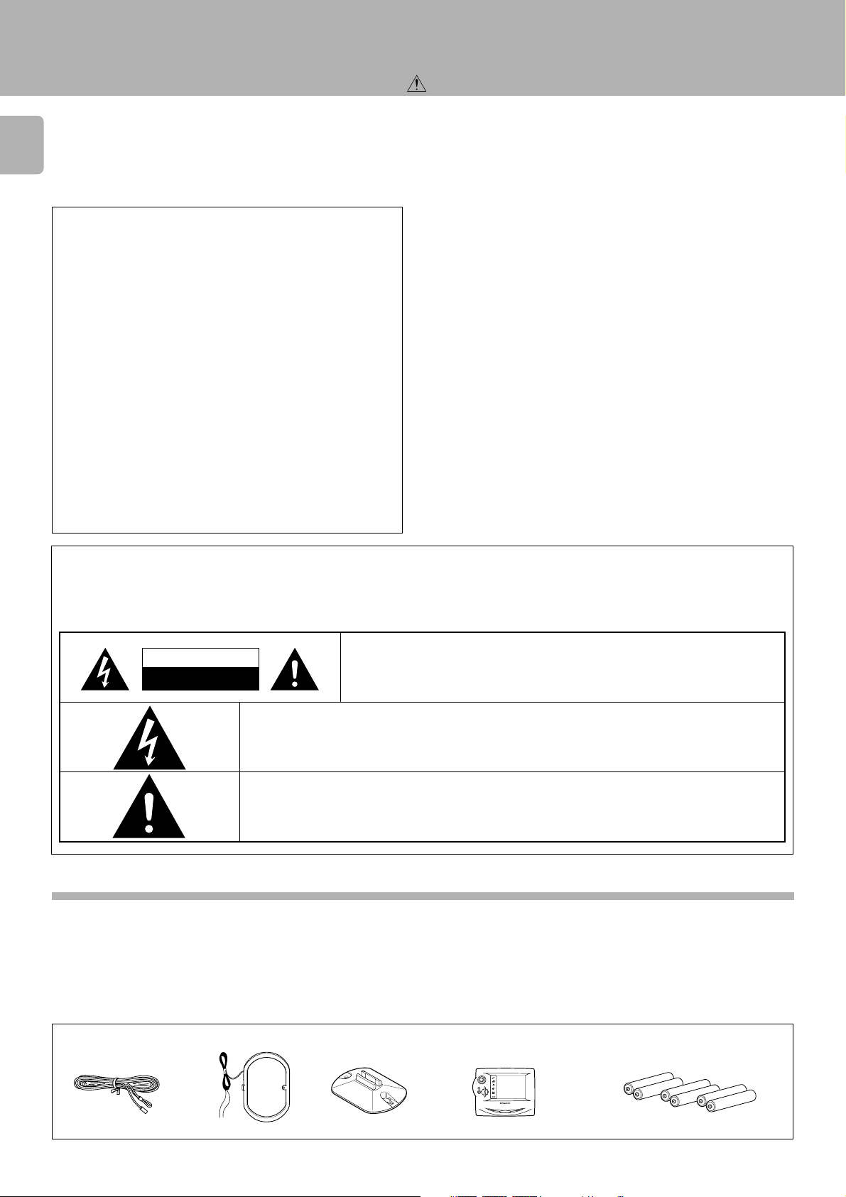
Accessories
FM indoor antenna (1) AM loop antenna (1) Loop antenna stand (1)
GRC-700 (1)
Batteries (R06/AA) (6)
Page 3

Before applying power
Contents
Caution : Read the pages marked
carefully to ensure safe operation.
Before applying power .........................................................................................................................................................................2
Safety precautions.......................................................................................................................................... 2
Unpacking ........................................................................................................................................................ 2
Special features .....................................................................................................................................................................................4
How to use this manual .......................................................................................................................................................................4
System connection ................................................................................................................................................................................5
Connection of audio components (CD player, MD recorder, cassette deck, power amplifier) .............. 5
Connection of video components (LD player, VCR, DVD) ............................................................................. 6
Digital connections........................................................................................................................................... 7
About the system control connections ........................................................................................................... 8
Connection of flat-cable connector ................................................................................................................ 8
Connection of antenna ..................................................................................................................................... 9
Using DVD 6ch INPUT ........................................................................................................................................................................ 10
Controls and indicators...................................................................................................................................................................... 11
Setup of the Graphical Remote Control (GRC) unit....................................................................................................................... 12
Controls and indicators ............................................................................................................................... 12
Operation of Graphcal Remote Control .............................................................................................................13
Setting up the GRC according to other components (Set Up).............................................................. 15
Remote control of components from the GRC................................................................................................................................ 18
Controlling the AV CONTROL CENTER...................................................................................................... 18
Controlling the components connected through system control cords ............................................ 19
Convenient functions...........................................................................................................................................................................22
One-touch operation features .................................................................................................................... 22
Easy operation feature.................................................................................................................................. 22
Speaker settings ..................................................................................................................................................................................23
Setup for surround play (SET UP) ............................................................................................................... 23
Playing music ...................................................................................................................................................................................... 27
Sound adjustment ............................................................................................................................................................................... 29
Setup for surround play (SOUND)............................................................................................................... 29
Recording.............................................................................................................................................................................................. 31
Recording an analog input source ............................................................................................................. 31
Recording a digital input source (CD, DVD) ............................................................................................. 33
Listening to radio broadcasts ........................................................................................................................................................... 38
Tuning radio stations.................................................................................................................................... 38
Functions of RDS ........................................................................................................................................... 39
RDS DISPLAY key........................................................................................................................................... 39
Presetting RDS stations (AUTO MEMORY) .............................................................................................. 40
Storing radio stations manually in preset memory................................................................................ 41
Receiving all preset stations in order (P. CALL) ..................................................................................... 42
Receiving a preset station .......................................................................................................................... 42
Searching for a desired program type (PTY search) ............................................................................. 43
Reserving the desired information (EON reservation) ............................................................................... 45
Ambience effects .................................................................................................................................................................................48
Surround modes ............................................................................................................................................ 48
Surround play (LISTEN MODE) ................................................................................................................... 50
To select the DSP mode (DSP) ................................................................................................................... 52
Listen mode selection.................................................................................................................................. 53
Clock adjustment .................................................................................................................................................................................54
Clock adjustment .......................................................................................................................................... 54
Displaying the Time...................................................................................................................................... 54
Timer operation ....................................................................................................................................................................................55
Timer programming ...................................................................................................................................... 55
Activating the timer...................................................................................................................................... 57
Sleep timer ..................................................................................................................................................... 58
Important Items.....................................................................................................................................................................................60
Maintenance................................................................................................................................................... 60
Reference ....................................................................................................................................................... 60
In case of difficulty ..............................................................................................................................................................................61
Specifications.......................................................................................................................................................................................63
3
Page 4
Special features
4
True home theater sound
DTS
DTS (Digital Theater Systems) is a 5.1 channel digital audio format that provides five full-spectrum channels and one low-frequency (subwoofer)
channel for unprecedented clarity, optimum channel separation and a (wide) dynamic range.
In the DTS mode, the 5.1 channel digital input from a DTS CD, LD or DVD disc (carrying the DTS marking) can be played in Digital Surround.
Important:
When a DTS disc is played on a CD, LD or DVD player, noise may be output from the analog output. It is recommended that you connect the
digital output of the player to the digital input of this unit.
Dolby Digital (AC-3)
The DOLBY DIGITAL (AC-3) mode lets you enjoy full digital surround from software processed in the Dolby Digital (AC-3) format. Dolby Digital
(AC-3) provides up to 5.1 channels of independent digital audio for better sound quality and more powerful presence than conventional Dolby
Surround.
Dolby Pro Logic & Dolby 3 Stereo
This surround system reproduces theater-like surround sound from video software marked .
The PRO LOGIC mode uses the built-in adaptive matrix circuit to steer the Left, Center, Right and Surround channel audio signals.
The 3 STEREO mode will redirect the surround signal to the front left and right speakers when only the front and center speakers are used.
DSP surround modes
The DSP (Digital Signal Processor) used for this AV CONTROL CENTER incorporates a variety of high quality adjustable sound fields, like
"ARENA", "THEATER", "JAZZ CLUB" to add the “presence” associated with an arena, theater, jazz club to the original signal.
process either PCM or analog sources.
Multi channel music (SRS Circle Surround)
SRS Circle surround enables you to listen to multi channel sound from the stereo source. We assume you have already enjoyed listening
to Dolby digital sound / DTS multi channel sound with your multi speakers. Now, this time try listening to the stereo source (ex. Audio CD)
using your multi speakers. You may discover a new type of “stereo” sound through SRS Circle Surround.
Before applying power
System connection
The DSP can
Graphical Remote Control unit ”GRC”
The GRC unit incorporates a large-screen LCD which displays key icons and parameters. The LCD also shows information on the operating
modes of the main unit. It incorporates sophisticated engineering and design to allow you to simply touch the screen to press buttons and
operate controls. You can touch the screen with your finger or with the stylus stored at the top of the GRC.
To improve the operability, frequently used icons are located in the higher hierarchy in the LCD display and icons which are associated
between each other are shown on the same screen.
The GRC unit is a multi-function remote control unit which can be programd to control AV components from other manufacturers than
KENWOOD.
RDS (Radio Data System) tuner
The tuner of this AV CONTROL CENTER provides the RDS reception capability with wide functionality: The AUTO MEMORY automatically
presets up to 40 RDS stations broadcasting different programs, the station name display shows you the name of the current broadcast station,
and the PTY search lets you tune stations by program type.
ONE TOUCH OPERATION
Simply pressing the play key of the CD player or cassettedeck turns the system on and starts playback.
Low standby power consumption
The power consumption during standby is no more than 1.6 W.
How to use this manual
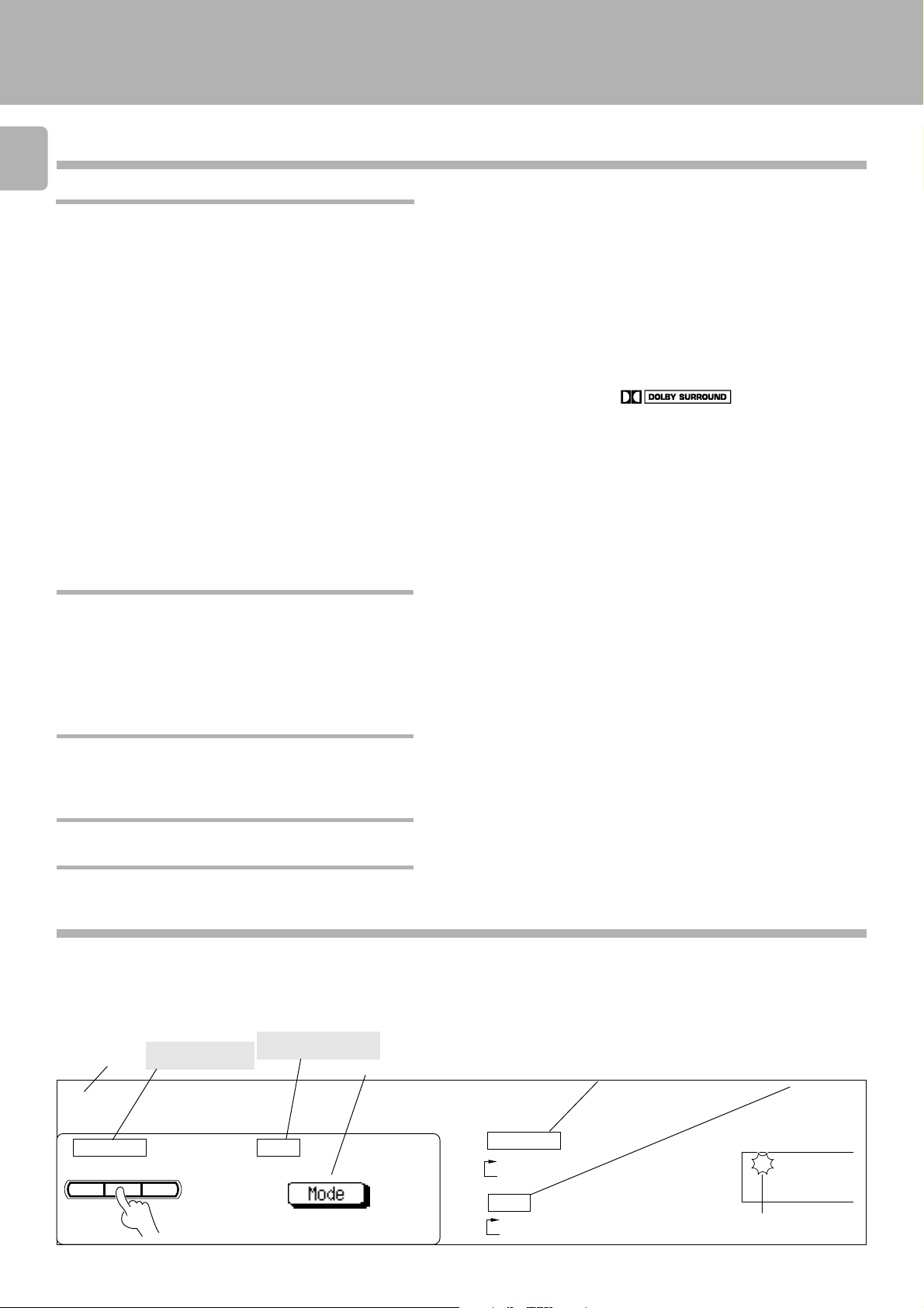
In this manual, the operating procedures are described on the left half of each page and the supplementary explanation,
display information and other notes on each step are described on the right half.
(Example of instructions in this manual)
Operating procedure steps
Remote control key to
be used
Step No.
Main unit key to be
used
(Left half)
Icon selection
Supplementary explanation
Supplementary
explanation for the main
unit operation
(Right half)
Supplementary
explanation for the
graphical remote
control operation
Select the tuning method.
3
Main unit GRC
A.MEMO
AUTO BAND
Main unit
1 AUTO lit (auto tuning)
2 AUTO not lit (manual tuning)
GRC
1 Auto (auto tuning)
2 Manual (manual tuning)
AUTO STEREO
MEMO.
TUNED
RDS
TP
EON
PTY TA NEWS
CLIP
MUTE
Lights up
FM
AM
MW
LW
Page 5
System connection
System connection
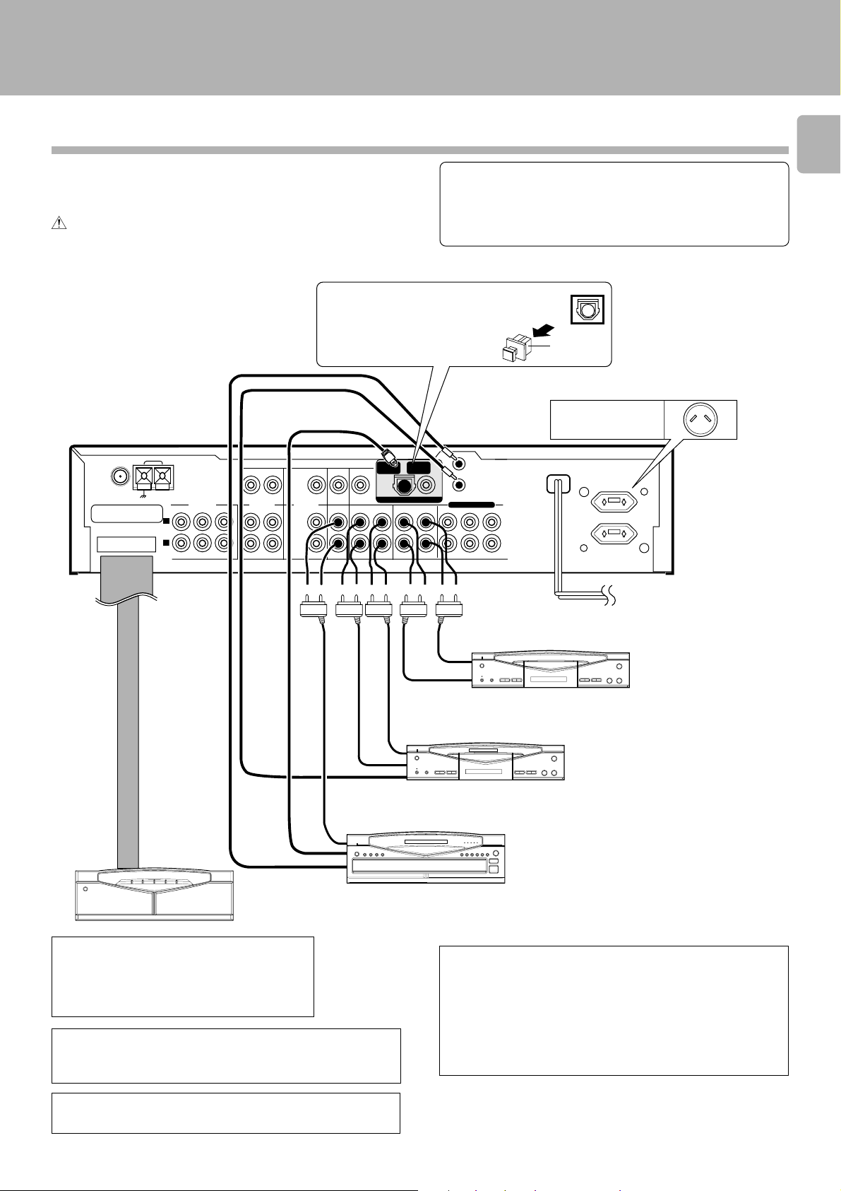
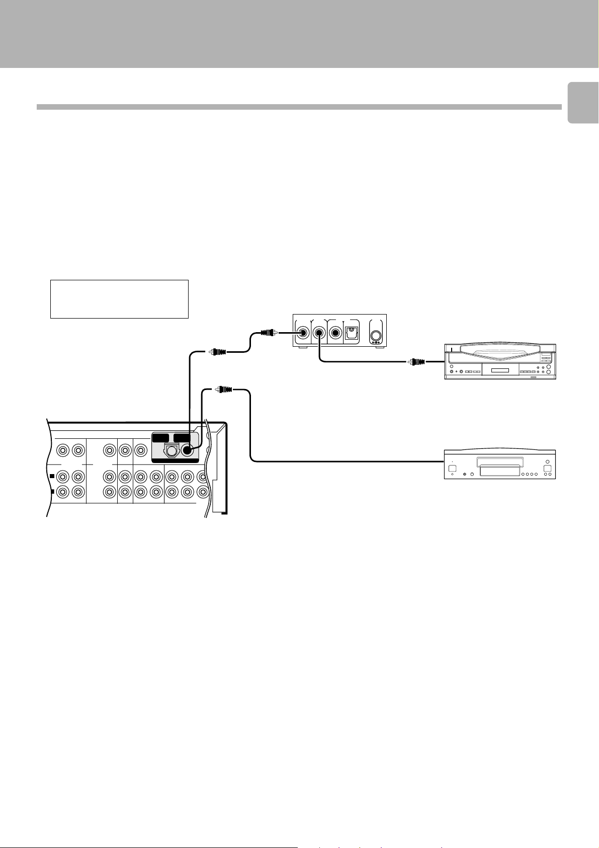
Connection of audio components
(CD player, MD recorder, cassette deck, power amplifier)
Make connection as shown below.
When connecting the related system components, refer
also to the instruction manuals of the related components.
Do not plug in the power lead until all connections are
completed.
DIGITAL IN jack
Remove the protective cap
before using the DIGITAL IN
jack.
System control cord
Optical fiber cable
ANTENNA
FM 75Ω
CONNECT
WITH
POWER AMPLIFIER
AM
GND
L
R
PREOUT
FRONT SURROUND CENTER
SUB WOOFER
PLAY
REC
VIDEO 1 VIDEO 2
PLAY
REC
VIDEO
PLAY
6CH.INPUT
PLAY PLAY
CD
(OPTICAL 1)
MONITOR
DVD/
CD
OUT
MD/TAPE1
REC
DIGITAL IN
PLAY
(COAXAL)
TAPE 2/MON
REC
Malfunction of microcomputer
If operation is not possible or erroneous display appears even
though all connections have been made properly, reset the
microcomputer referring to “In case of difficulty”.
Remove cap
Shape of AC outlet
Australia x 1
DVD
PLAY
SYSTEM
CONTROL
DVD/6CH.INPUT
FRONT SURROUND CENTER
SUB WOOFER
UNSWITCHED
5
Œ
REC
IN
Connection
cable
LINE
OUTPUT
System control cord
1
Power amplifier
*
M-A300
*1 For the connection and operation proce-
dures of the power amplifier and speakers, refer to the instruction manual of
the power amplifier (M-A300).
Also connect the system control cords when the
KENWOOD Audio Component System “SERIES 21” is
connected.
PLAY
OUT
To wall
AC outlet
PLAY
OUT
2
Cassette deck 2
*
REC IN
MD recorder or
Cassette deck 1
CD player
The connected components shown here are given as examples
because the available models vary depending on marketing areas.
Caution regarding placement
Be sure to adhere followings. Or proper ventilation will be
blocked causing damage or fire hazard.
÷ Do not place any objects impairing heat radiation onto the top of
unit.
÷ Leave a space around the unit (from the largest outside dimension
including projection) equal or greater than, shown below.
Top panel : 50 cm Side panel : 10 cm Back panel : 10 cm
*2Do not connect system control cord to the cassette
deck connected to the TAPE 2/MONITOR jacks.
Page 6
System connection
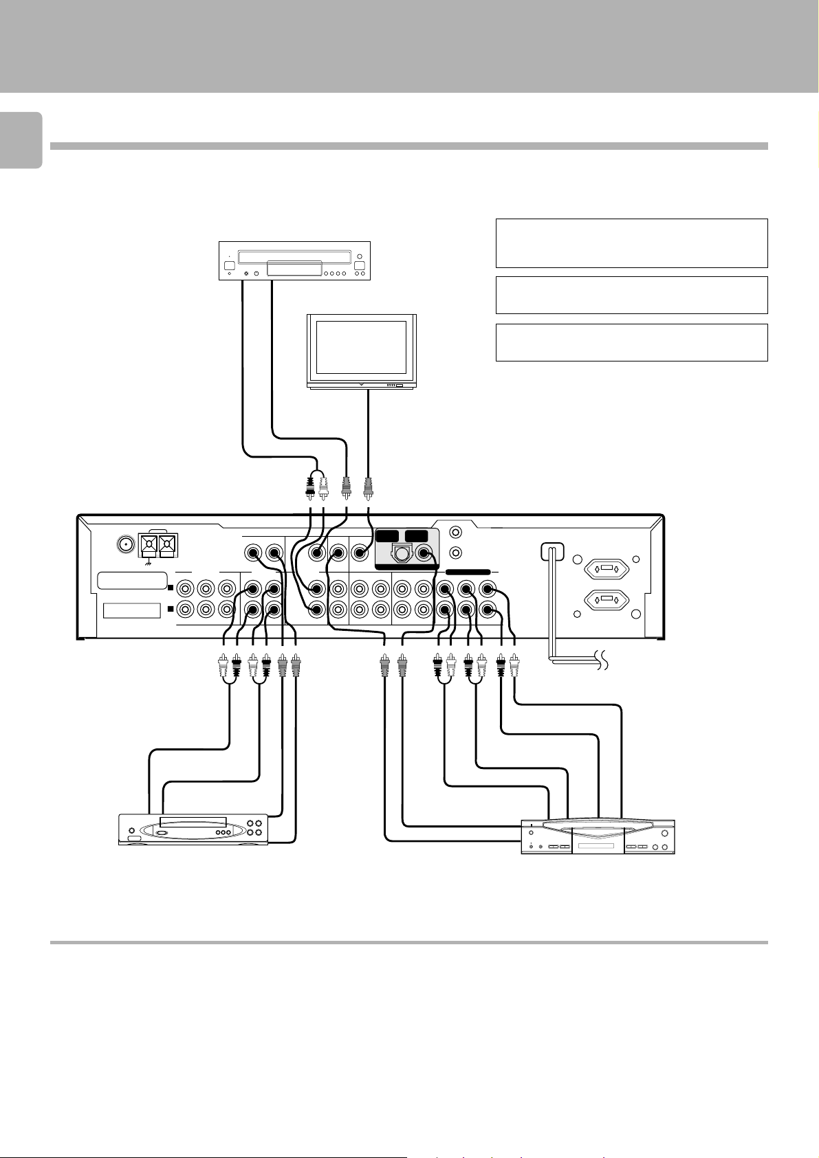
Connection of video components
6
LD player *1
Video
OUT
PLAY
REC
VIDEO 1 VIDEO 2
PLAY
REC
VIDEO
PLAY
PLAY PLAY
Monitor TV
Video
IN
(OPTICAL 1)
MONITOR
DVD/
OUT
6CH.INPUT
CD
MD/TAPE1
PLAY
REC
CD
ANTENNA
FM 75Ω
CONNECT
WITH
POWER AMPLIFIER
AM
GND
L
R
Audio
OUT
PRE OUT
FRONT SURROUND CENTER
SUB WOOFER
(LD player, VCR, DVD)
*1
When using an LD player of Series 21, connect it
to the DVD/6CH INPUT.
When using a cable or satellite tuner, connect it to
the VIDEO 2 input.
*2
When using DVD 6ch INPUT.
DVD
(COAXAL)
SYSTEM
DIGITAL IN
DIGITAL IN
TAPE 2/MON
REC
PLAY
CONTROL
DVD/6CH.INPUT
FRONT SURROUND CENTER
SUB WOOFER
0
UNSWITCHED
2
*
Audio CENTER OUT
Audio SUBWOOFER OUT
Audio IN
Audio SURROUND OUT
Audio OUT
Video IN
Audio FRONT OUT
Audio DIGITAL OUT
Video OUT
Video OUT
DVD
VCR
The connected components are given as examples because the available models vary depending on marketing areas.
DTS disclaimer clause
DTS Digital Surround™ is a discrete 5.1 channel digital audio format available on CD, LD, and DVD software which consequently cannot be
decoded and played back inside most CD, LD, or DVD players. For this reason, when DTS-encoded software is played back through the
analog outputs of the CD, LD, or DVD player, excessive noise will be exhibited. To avoid possible damage to the audio system, proper
precautions should taken by the consumer if the analog outputs are connected directly to an amplification system. To enjoy DTS Digital
Surround™ playback, an external 5.1 channel DTS Digital Surround™ decoder system must be connected to the digital output (S/PDIF, AES/
EBU, or TosLink) of the CD, LD or DVD player.
This unit is equipped with DTS Digital Surround™ decoder.
Page 7
System connection
Digital connections
Make connections as shown below.
The digital in jacks can accept DTS, Dolby Digital (AC-3) or PCM signals. Connect components capable of outputting DTS, Dolby
Digital (AC-3) or standard PCM (CD) format digital signals.
When connecting the related system components, be sure to also refer to the instruction manuals supplied with the
components you are connecting.
Do not connect the power cord to a wall outlet until all connections are completed.
Connect components capable of outputting Dolby Digital (AC-3) or standard PCM
format digital signals.
An LD player and DVD player cannot be connected simultaneously
when an RF demodulator is used.
AC-3 DIGITAL OUT
To connect an LD player with a DIGITAL RF OUT.
Connect the LD player to the KENWOOD RF digital demodulator (DEM-9991D).
Then connect the demodulator to the AC-3 AUDIO INPUT DIGITAL IN.
Connect the video signal and analog audio signals to LD jacks (See "Connection
of video components".)
DIGITAL OUTPUT
RF INPUT
AC-3 RF
DIGITAL INPUT
COAX. OPT.
COAX.
DC IN
To connect an LD player
6
with a DIGITAL OUT
AC-3 RF OUT
RCA pin cord
7
PLAY
REC
VIDEO 1 VIDEO 2
L
R
PLAY
REC
VIDEO
PLAY
PLAY
DVD/
6CH.INPUT
CD
PLAY
MONITOR
OUT
MD/TAPE 1
REC
CD
(OPTICAL 1)
PLAY
DIGITAL IN
TAPE 2/MON
REC
DVD
(COAXAL)
PLAY
AC-3 RF Demodulator
(DEM-9991D) (option)
To connect a DVD player
with a DIGITAL OUT
COAXIAL DIGITAL OUT
FRONT
Connect the video signal and analog audio
signals to the DVD jacks.
(See "Connection of video components".)
6
The connected components are given as examples because the available models vary depending on marketing areas.
Page 8
System connection
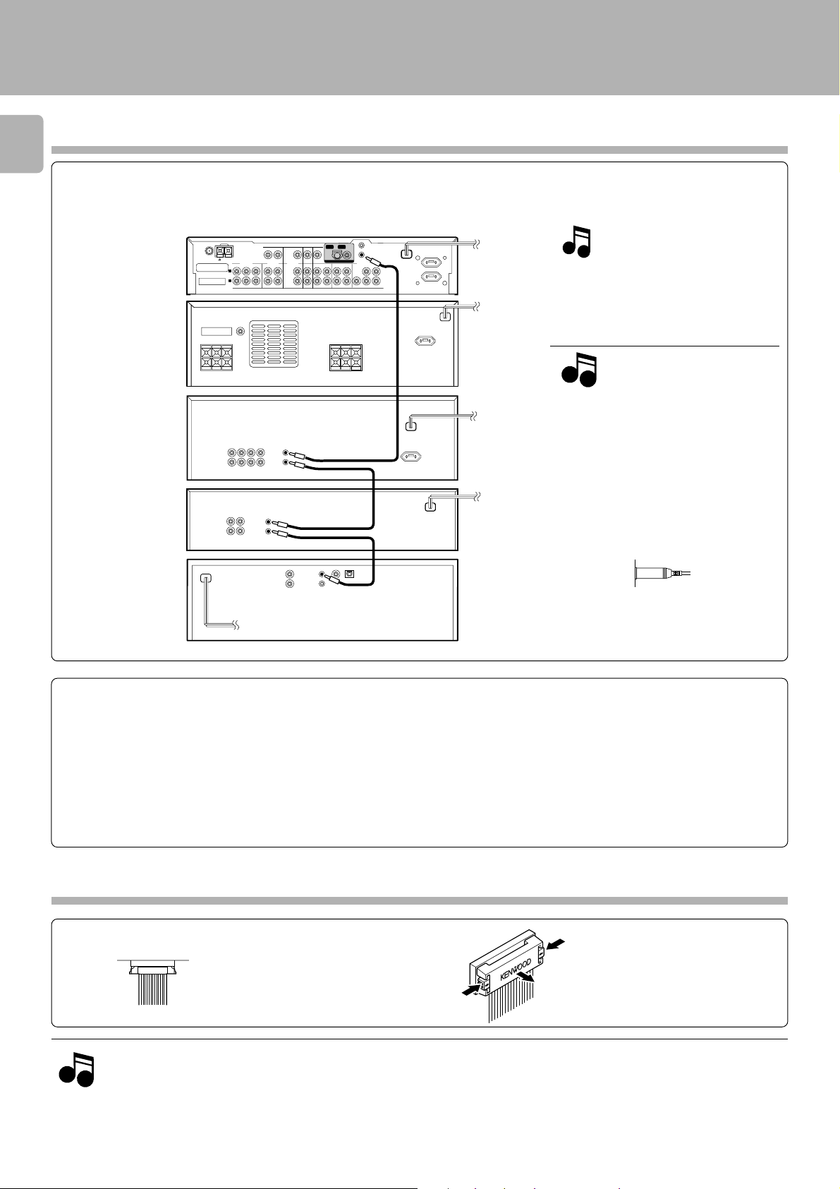
About the system control connections
8
When this unit is connected to KENWOOD audio component system “SERIES 21”, also connect them through the system control cords
to allow system-control operations between components.
Connection example
AM
AV
CONTROL
CENTER
POWER
AMPLIFIER
GRAPHIC
EQUALIZER
MD recorder
ANTENNA
CONNECT WITH
POWER AMPLIFIER
FM 75Ω
GND
L
R
SYSTEM
CONTROL
SYSTEM
CONTROL
SYSTEM
CONTROL
System
control cord
System
control cord
UNSWITCHED
The SERIES 21 components which can be
system-connected with this unit include
the LD player, MD recorder and DVD player.
NotesNotes
Notes
1. Do not connect the SERIES 21 components
to other system components using system
control cords.
2. Do not connect system control cords to any
components other than those specified by
KENWOOD. It may cause a malfunction and
damage your equipment.
3. Be sure the system control plugs are inserted all the way in to the system control
terminals.
CD
SYSTEM
CONTROL
System
control cord
PLAYER
About the system control operations
(Available operations when SERIES 21 components are connected through system control cords)
Remote Control *
Lets you operate source components with the system remote supplied with this unit.
Automatic Operation ™
When you start playback from a source component, the input selector on this unit switches to that component automatically. (Except TAPE 2)
Synchronized Recording ⁄
Lets you synchronize recording with the start of playback when recording from CD etc.
Connection of flat-cable connector
Inserting the connector
Push in the
connector straight
into the socket until it
clicks to indicate the
locking.
Removing the connector
Push and hold the two ends of the
connector, and pull it straight
outward.
NotesNotes
Notes
1. Connect all cords firmly. If connections are loose, there could be loss of sound or noise produced.
2. When plugging and unplugging connection cords, be sure to first remove the power cord from the AC outlet. Plugging / unplugging
connection cords without removal of the power cord can cause malfunctions or damage to the unit.
3. Do not connect up a power source which is larger than that indicated on the socket at the rear of the unit.
4. If the system control cords or audio cords are not connected properly, the remote control or automatic operation between system
components will not work properly.
Page 9
System connection
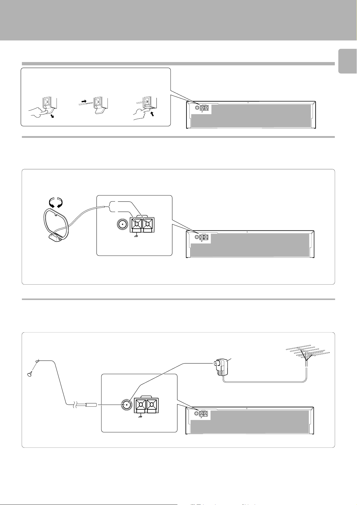
Connection of antenna
Connection method to each antenna terminal
1 Push lever. 2 Insert cord. 3 Return lever.
AM loop antenna connection
The supplied antenna is for indoor use. Place it as far as possible from the
main system, TV set, speaker cords and power cord, and set it to a
direction which provides the best reception.
ANTENNA
FM 75Ω
AM
GND
9
AM
ANTENA
FM 75Ω
GND
AM
ANTENA
FM 75Ω
GND
FM indoor antenna connection
The accessory antenna is for temporary indoor use only. For stable signal
reception we recommend using an outdoor antenna. Remove the indoor
antenna if you connect one outdoors.
ANTENNA
FM 75Ω
AM
GND
FM outdoor antenna connection
Lead the 75 Ω coaxial cable connected to the FM outdoor antenna into
the room and connect it to the FM 75 Ω terminal.
Use the commercially
available antenna adaptor.
AM
ANTENA
FM 75Ω
GND
Page 10
D
Using DVD 6ch INPUT
10
Opening/closing the door
1 Press the ON/STANDBY key to ON.
System connection
2 Opening/closing the door
ON/STANDBY
OPEN/CLOSE
Note
Note
When opening or closing the door, be careful not to catch
your finger in the door. Otherwise there is a risk of injury.
Changing the input selection display (AUTO key)
To make the system control operation, the input selection display should be switched according to the actually connected components.
About the system control connections
To change the DVD display into the DVD 6CH display or LD display.
Main unit
1 Select “DVD” with the INPUT SELECTOR .
INPUT
GRC
o
e
i
v
m
2 Press the INPUT MODE key.
8
INPUT MODE
EMO
AUTO BAN
o
d
e
m
n
e
t
s
i
l
Select the “Input Analog” icon.
3 Press and hold the AUTO key for more
than 2 seconds, until “DVD 6ch” is
displayed. (Main unit only)
Analog input
Each press switches the indication.
1 DVD 2 DVD 6ch 3 LD
Digital input
Each press switches the indication.
1 DVD 2 LD
Page 11
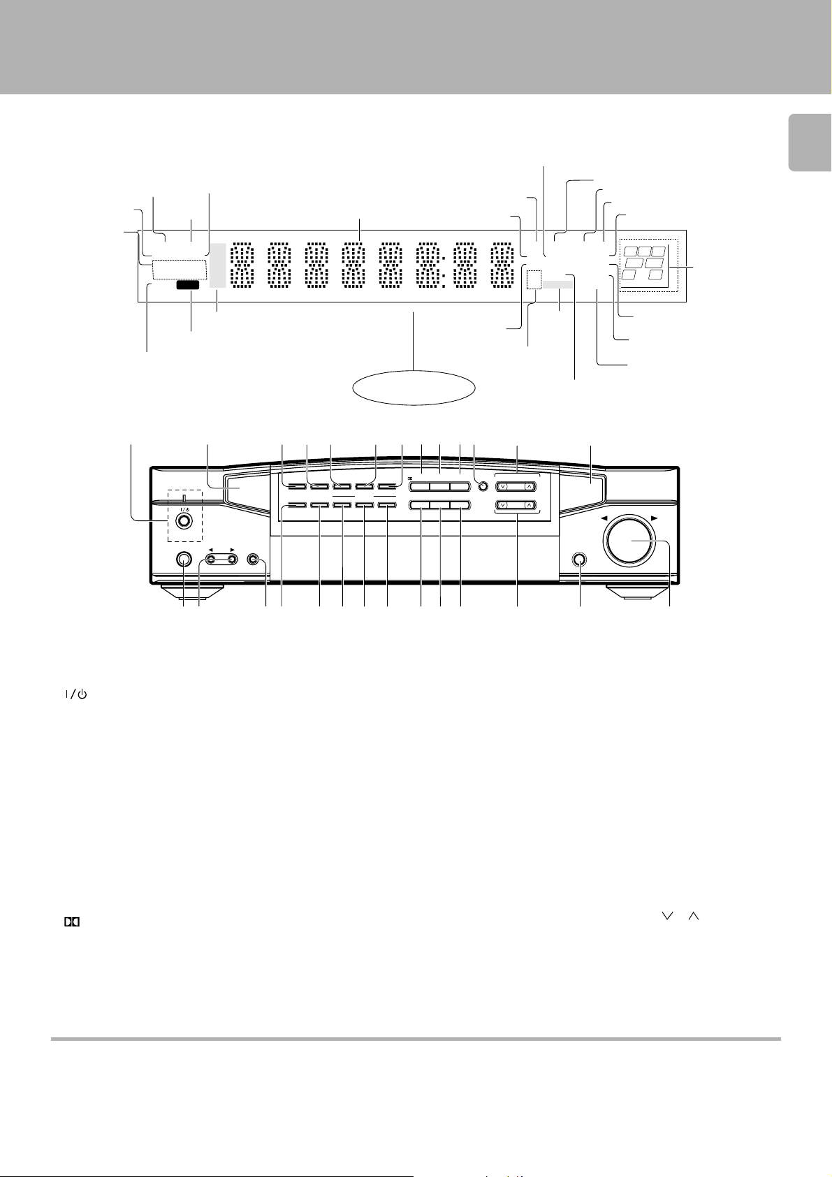
Controls and indicators
System connection
AUTO tuning mode
Memory indicator
RDS indicators
TUNED indicator
STEREO
indicator
AUTO STEREO
MEMO.
RDS
EON
PTY TA NEWS
MUTE
CLIP indicator
MUTE indicator
1
ON/STANDBY
PHONES
FM
TUNED
AM
TP
MW
LW
CLIP
Broadcast band indicators
(AM : Australia only)
2
TAPE 2
INPUT
/ MONITOR
Frequency display, input selector
display, preset channel display,
surround mode display
Display
4 5
TIMER
DIGITAL
SET
REC MODE
TIMER
CLOCK
MODE
SET UP
DISPLAY
SOUND
INPUT MODE
RDS
PTY
TA/NEWS
DOLBY DIGITAL indicator
11
SOUND indicator
DIGITAL REC
3 STEREO
DOWN MIX
TAPE2/MONI.
#
OPEN/CLOSE
DIGITAL indicator
REC indicator
CS indicator
L
CS
C
LFE
LS
S
3 STEREO indicator
STEREO indicator
DOWN MIX indicator
TAPE 2/MONI. indicator
VOLUME CONTROL
DOWN
Speaker selection
R
SW
RS
UP
indicators
Input channel
indicators
Output channel
indicators
AUTO indicator
DTS indicator
AUTO SOUND
DTS DOLBY DIGITAL
PRO LOGIC
MHz SLEEP
KHz TIMER 1 2
@
MULTI.CONTROL
LEVEL
PTY SELECT
TUNING
TIMER
indicators
SLEEP indicator
PRO LOGIC
indicator
Receiving frequency
unit indicators
73
9 08
!6
LISTEN
CIRCLE
DTS
DIGITAL
A.MEMO
AUTO BAND
SURROUND
MODE
% ¶
^
&* )¡(™£¢∞
The keys which have the same names as the controls on the
remote control unit provide the same functions as them.
1 (ON/STANDBY) key/indicator
Press to switch between ON and STANDBY.
0
2 Remote sensor
3 TIMER SET key
Press to set the timer function.
4 DIGITAL REC MODE key ›
Use to select the DIGITAL REC mode.
5 SET UP key £
Use to select the surround sound settings.
6 SOUND key ª
Use to adjust the sound quality and ambience effects.
7 INPUT MODE key *
Use to switch between the digital and analog
inputs.
T
8 DIGITAL key p
Use to select the Dolby digital mode.
9 DTS key p
0 CIRCLE SURROUND key p
! LISTEN MODE key p
Use to select the listening mode.
@ MULTI. CONTROL key R
Press to select various setting modes.
These keys are also used in the clock adjustment and timer operations.
# GRC transmitter
Outputs the signals transmitted to the
Graphical Remote Control.
$ PHONES jack •
For use in headphones listening.
% INPUT SELECTOR keys 0
Press to select the input.
^ TAPE 2/MONITOR key •
For use in monitoring of recording, etc.
& TIMER MODE key T
Press to switch the timer modes.
* CLOCK key R
Press when setting the clock.
( RDS DISPLAY key ·
Press to switch the RDS display.
) RDS PTY key e
For use during reception of RDS broadcasting.
§$
¡ RDS TA/NEWS key y
For use during reception of RDS broadcasting.
™ A.MEMO key ‚
Press when using the auto memory function.
£ AUTO key 0°
Press to select the tuning mode.
The auto tuning or manual tuning mode can
be selected.
Pressing and holding this key for more than
2 seconds changes the MD input display to
TAPE 1 display or the DVD input display to
DVD 6ch INPUT or LD display.
¢ BAND key °
Press to switch the broadcasting band.
∞ TUNING keys ( , ) °
Press to select the radio station to be received.
§ OPEN/CLOSE key 0
¶ VOLUME CONTROL knob •
Standby mode
While the standby indicator of the unit is lit, a small amount of current is flowing into the unit’s internal circuitry to back up the memory. This condition
is referred to as the standby mode of the unit. While the unit is in the standby mode, it can be turned ON from the remote control unit.
Page 12
Setup of the Graphical Remote Control (GRC) unit
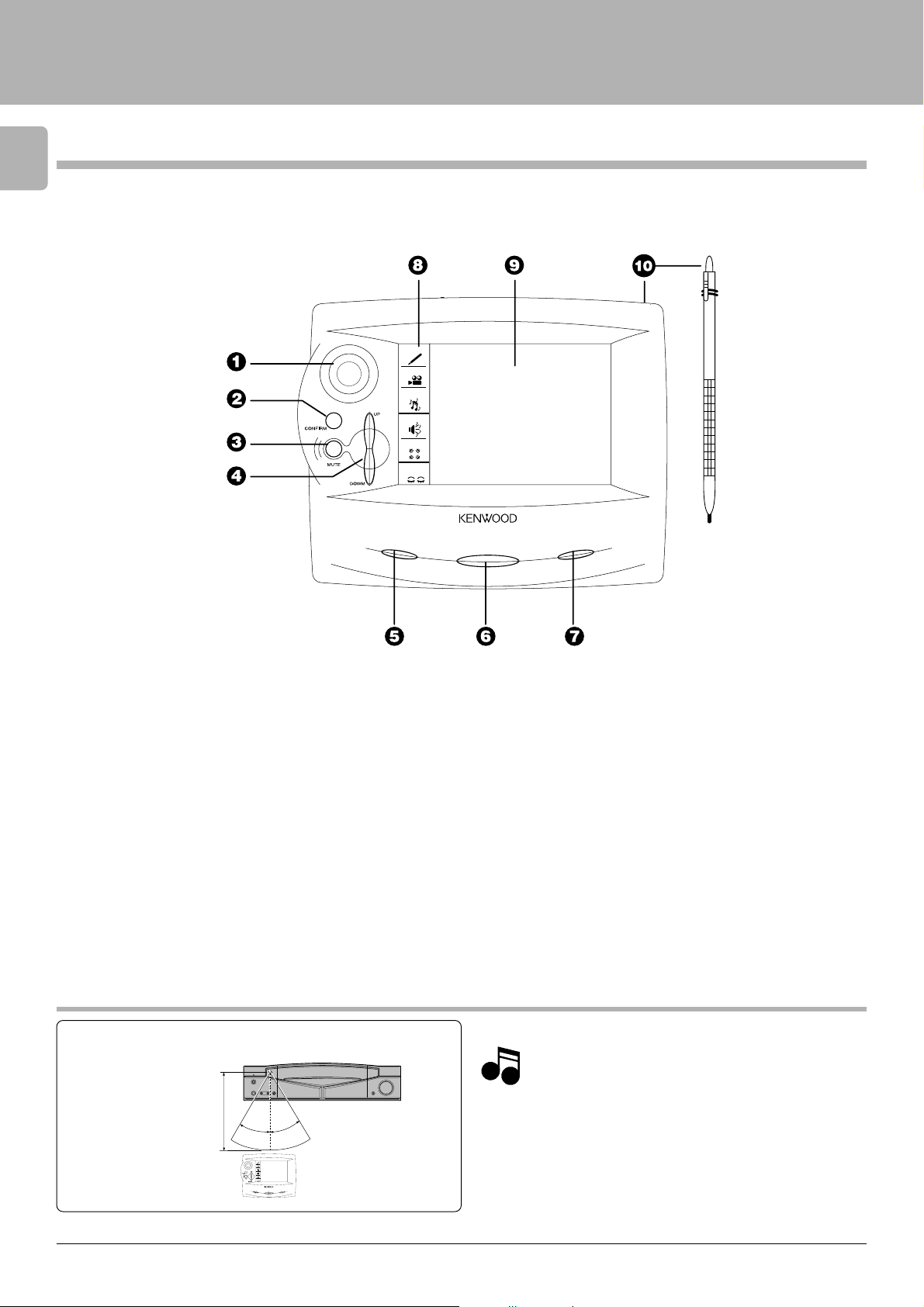
Controls and indicators
12
Setup of the Graphical Remote Control (GRC) unit
The Graphical Remote Control (GRC) unit provided with the AV CONTROL CENTER can also control KENWOOD cassette decks,
CD player, MD recorder and LD player which are connected to it through system control cords. For details of the controllable
functions, refer to the instruction manuals of these components.
Model: GRC-700
Infrared system
d
i
t
e
o
m
ENTER
E
M
U
L
O
V
v
i
e
s
u
i
c
m
u
o
n
s
d
n
m
e
t
o
s
i
d
l
e
e
e
l
p
s
1 Joystick $
2 Confirm button $
3 Mute button •
4 Volume up/down button
¶
5 Contrast button $
6 On/Standby button ¶
7 Backlight button $
CONTRAST
ON/STADBY
POWER
8 Quick Access menu *
edit : Editing feature
movie : Movie device controls such as DVD
players or VCRs.
music : Music device controls such as CD
players or the radio tuner.
sound : Sound controls, such as ”midnight“
mode.
listen mode : Listen modes such as stereo, Dolby
Digital.
sleep : Sleep timer
9 Touch screen display #
0 Stylus (stored on top edge)
#
Approximate operating range
Remote sensor
30°6m30°
GRC
Infrared ray system
d
i
e
t
o
m
v
ENTER
i
e
u
s
i
m
c
u
o
n
s
d
E
M
U
L
O
V
n
m
e
t
o
s
i
l
d
e
e
l
e
s
p
CONTRAST
ON/STADBY
POWER
Infrared remote control
1. The supplied batteries are intended for use in operation check.
NotesNotes
Notes
Therefore, their lives may be shorter than ordinary batteries.
2. When the remote-controllable distance gets shorter than
before, replace all 6 batteries with new ones.
3. Malfunction may occur if direct sunlight or the light of a highfrequency lighting fluorescent lamp enters the remote sensor. In such a case, change the system installation position to
prevent the malfunction.
4. The GRC display may show erroneous information when the
GRC unit is operated from outside the specified range.
5. The GRC unit may display incorrect information when the
communication is not normal.
In such a case, press the CONFIRM button.
Page 13
Setup of the Graphical Remote Control (GRC) unit
Operation of Graphcal Remote Control
Perform the following procedure after inserting batteries for
the first time and every time after changing them.
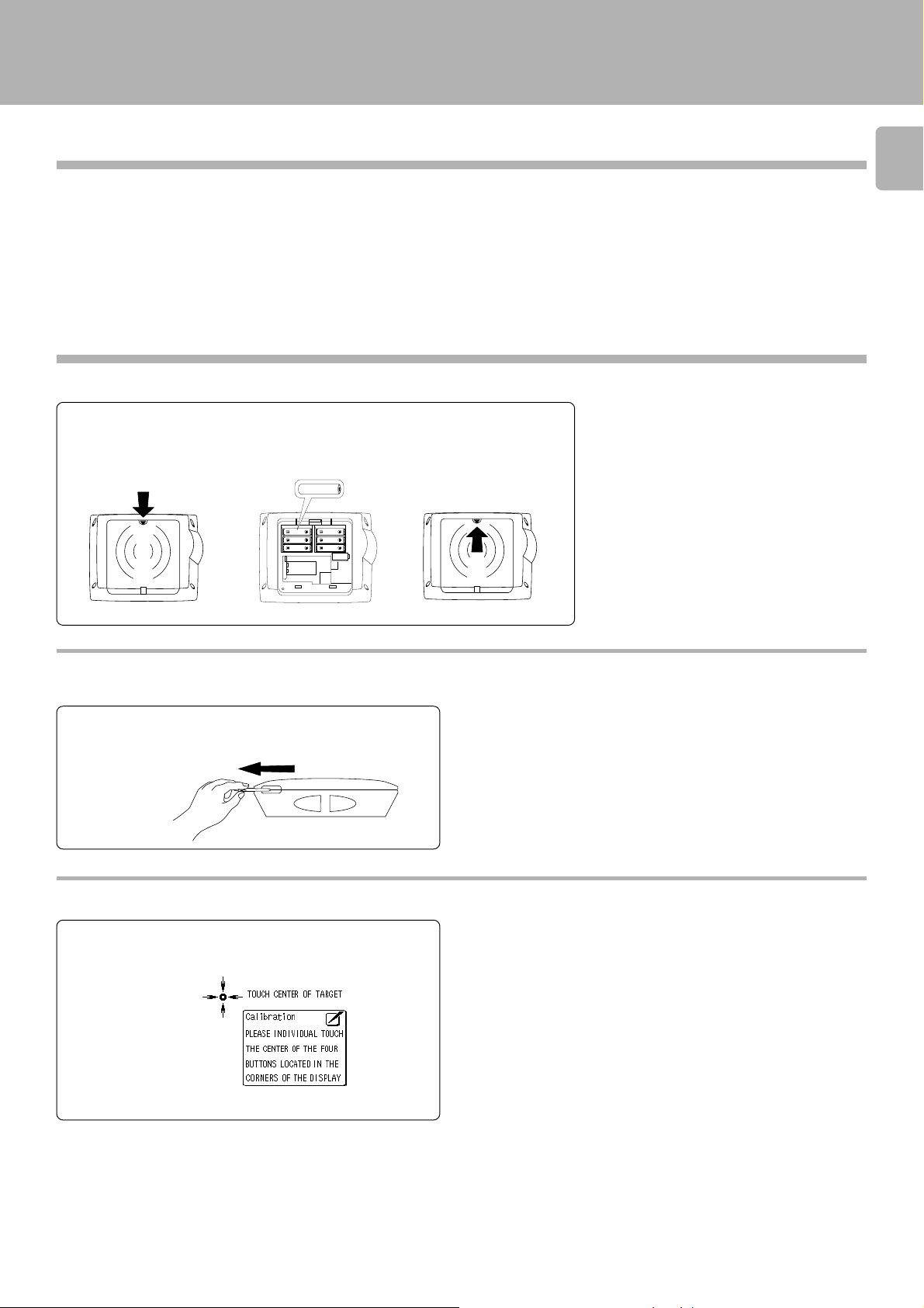
Loading the batteries
Loading batteries
1 Remove the cover. 2 Insert batteries. 3 Close the cover.
·
ª
13
Caution in battery replacement
÷ Insert 6 AA-size batteries as indicated by the
polarity marking.
÷ To maintain the memory of the settings you
made before, complete the battery replacement operation within 30 seconds.
Remote control operation
1 The touch screen responds to pressure
from the included stylus or your finger.
Calibrating the Touch screen
1 To calibrate the touch screen, use the
stylus to touch the center of each of the
calibration points displayed.
÷ When you touch each calibration point, you should hear a beep and see
the next point, indicating that area of the screen is now calibrated. If
you do not hear a beep, touch the calibration point until you do.
÷ The touch screen is sensitive to pressure, not to movement. Press
firmly but gently on any touch screen element. The screen will not
respond if you simply brush the stylus or your finger along the surface.
÷ If you are replacing batteries and complete the battery replacement
within 3 minutes, you do not need to calibrate the screen; calibration
is stored in memory.
Page 14
14
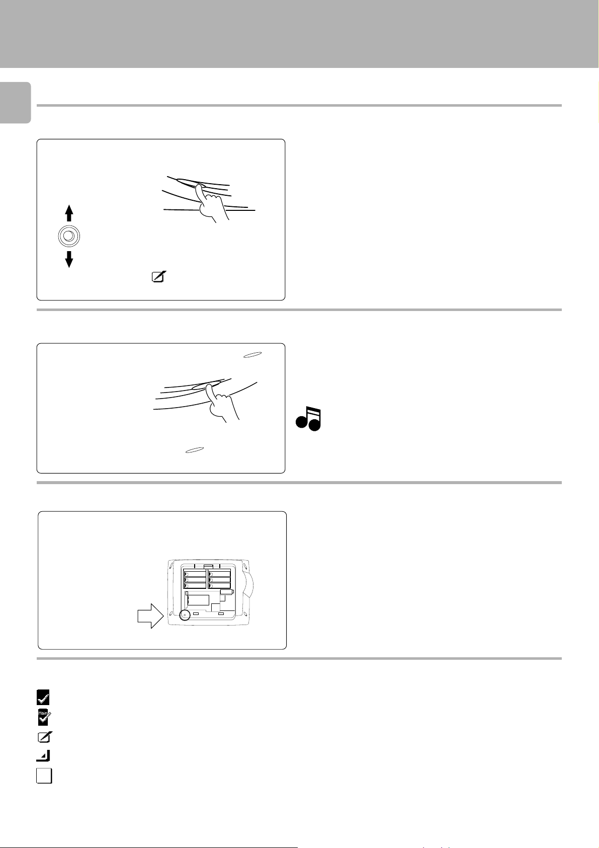
To adjust the contrast
1 Press the CONTRAST button until “Con-
trast” message appears on the screen.
Setup of the Graphical Remote Control (GRC) unit
CONTRAST
ENTER
2 While this message is displayed, move
the joystick up or down to increase or
decrease the contrast until you are satisfied.
3 Press the save the contrast setting
and return to the control screen.
Backlight botton
1 To use GRC in the dark, press
Backlight
2 To turn off the light and return to normal
display , press
BACKLIGHT
Resetting the GRC unit
1 Open the cover.
2 Use the stylus to press the blue button at
the bottom of the battery case.
again.
BACKLIGHT
.
÷ Backlight is automatically turned off when GRC goes to “sleep”–you
will need to turn it on again when you reactivate GRC.
Keep the Back Light turned off during normal use to
maximize the life of your batteries.
Note
Note
÷ If you are replacing batteries and complete the battery replacement
within 3 minutes, you do not need to calibrate the screen; calibration
is stored in memory.
÷ The setups made by the user are not cleared.
Icons
................ Return to previous display
............... Return to the main menu
.............. Quit the current display
............... Go to the next hierarchy level
............... Normal frame
To reset to the factory setup
÷ While pressing and holding the CONFIRM and VOLUME DOWN
button, use the stylus to press the blue button at the bottom of the
battrey case.
Page 15
Setup of the Graphical Remote Control (GRC) unit
Setting up the GRC according to other components (Set Up)
In the initial condition, the setup codes for CD, MD and DVD
have already been pre-registered. The GRC can also be used
to remote control other components which are not connected through system control cords.
In the operations of the GRC (Graphical Remote
Control unit), proceed to each step within 10
seconds after the previous step.
The display disappears in 10 seconds.
To resume GRC display, move the Joystick in any directions.
Registering setup codes for VIDEO 1
Enter the setup code.
1
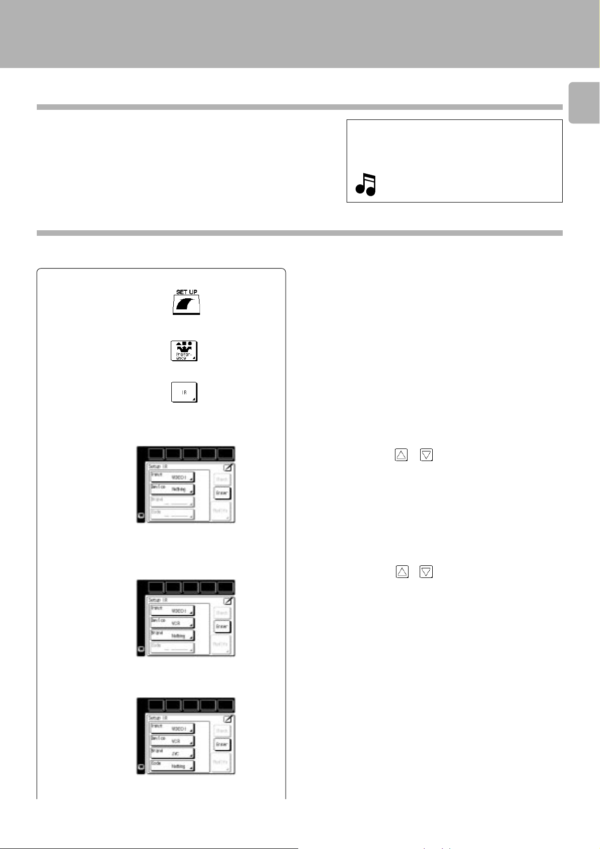
1 Select the ”SET UP“ icon.
2 Select the ”Preference“ icon.
3 Press the ”IR“ icon.
15
4 Press the ”Input“ icon to open the list of available jack
sets.
5 Press the “Device” icon to select the type of device you
have connected to the jack set.
6 Press the “Brand” icon to select the device’s brand.
Select the icon with or .
1 CD
2 MD/TAPE 1
3 VIDEO 1
4 VIDEO 2
5 DVD/DVD 6CH
6 TV 1
7 TV 2
8 TAPE 2/MONI.
Select the icon with or .
1 CD
2 TAPE
3 MD
4 VCR
5 CABLE
6 SATELLITE
7 TV
8 LD
9 DVD
0 Nothing
Continued to next page
Page 16
16
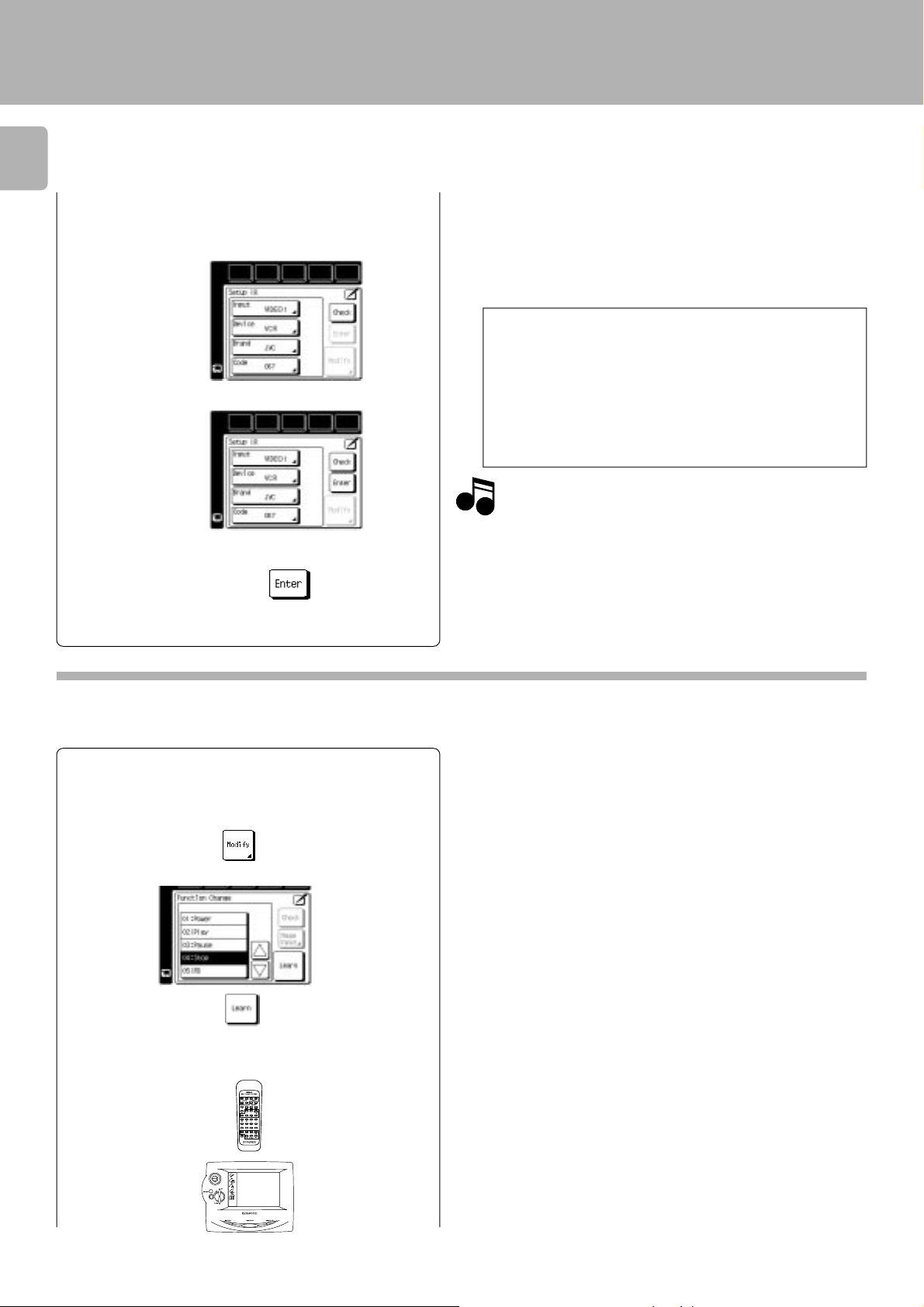
7 Press the “Code” icon. You can now choose from a list of
all the codes available for the device. Select the first code
on the list.
8 Press the “Check” icon.
9 Press the “Enter” icon.
Set up other components in the same way as above.
Setup of the Graphical Remote Control (GRC) unit
÷ When a code which is not shown in the setup code chart is entered,
the entered code disappears automatically.
÷ Even when the system control code is connected, some models may
not automatically display the “System” screen.
÷ With CD-Carrousel, select “Sys-carrousel”.
÷ When CD, MD and TAPE are connected through system control
cords, select “System”.
Check the operation of the component.
1 Display the operation screen of the component to be checked.
2 Turn on the component from the GRC and confirm the actual
component.
÷ If there is more than one setup code, select the “Check” icon.
This instructs GRC to send a “Power” test signal to the receiver.
If your device turns on, the code you entered was correct. If it
does not turn on, try the next code in the list. Continue until one
of the codes works.
Although each setup code is designed to work with a
number of different models, certain codes may not work
Note
Note
with some models. (Also, certain codes may only operate some of the functions available on a given model.)
With some models, be sure to keep the Check icon
pressed for a while.
÷ If the device power cannot be turned ON/OFF, return to 7 and select
the net code in the list.
Repeat 7 and 8 until the device power can be turned ON and OFF
properly.
Programming remote control functions
Remote control functions of some components may not be available even after the setup codes have been registered. In this
case, required functions can be programmed as if the GRC unit “learns” them.
To program STOP as a new control item
1 Perform steps 1 to 4 in 1.
2 Press the “Modify” icon.
3 Select the function to be programmed.
4 Aim the device’s remote at GRC and press and hold the
button on the device’s remote that corresponds to the
command you want GRC to learn.
10 cm
÷ This may take a few seconds; do not move GRC or the device’s remote
until GRC displays the the Function change menu again.
÷ Be sure to use the device’s original remote. GRC will not learn
commmands from other universal remotes.
Continued to next page
Page 17
5 Repeat steps 2 through 4 until you have taught GRC all the
commands you want it to know. If you need more lines,
touch or to access more lines.
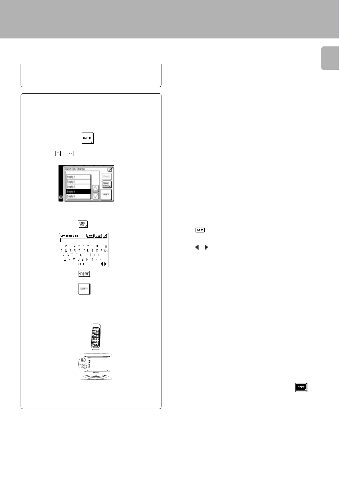
Programming an additional function which is not displayed in the screen
1 Repeat steps 1 and 2 in “To program STOP as a new
control item”.
2 Press the “Modify” icon.
3 Press the or icon to select one of
“Empty 1 to 8”.
^
Setup of the Graphical Remote Control (GRC) unit
17
4 Assign a name to the function.
5 Aim the device’s remote at GRC and press and hold the
button on the device’s remote that corresponds to the
command you want GRC to learn.
10 cm
÷ The name can be composed using up to 8 characters.
÷ Touch to access to lowercase characters. Touch it again to
access special characters (such as @, !, &, etc.). Touch it a third time
to return to uppercase characters.
÷ Touch
÷ Touch BS (Backspace) to clear the last caracter you entered. Touch
ALL DEL to delete all the characters in the line.
÷ This may take a few seconds; do not move GRC or the device’s remote
until GRC displays the Function change menu again.
÷ Be sure to use the device’s original remote. GRC will not learn
commmands from other universal remotes.
or to move back and forth between the characters.
6 Repeat steps 2 through 5 until you have taught GRC all the
commands you want it to know. If you need more lines,
touch or to access more lines.
÷ The additionally programmed function is registered in the
area.
Page 18
Remote control of components from the GRC
ENTER
V
O
L
U
M
E
UP
DOWN
CONFIRM
ON/STANDBYCONTRAST BACKLIGHT
Controlling the AV Control Center
18
Remote control of components from the GRC
The operations required to remote control the AV Control
Center includes the INPUT SELECTOR selection, display
mode selection, stereo selection and so on.
The following procedures show how to remote control the
basic operations of the GRC.
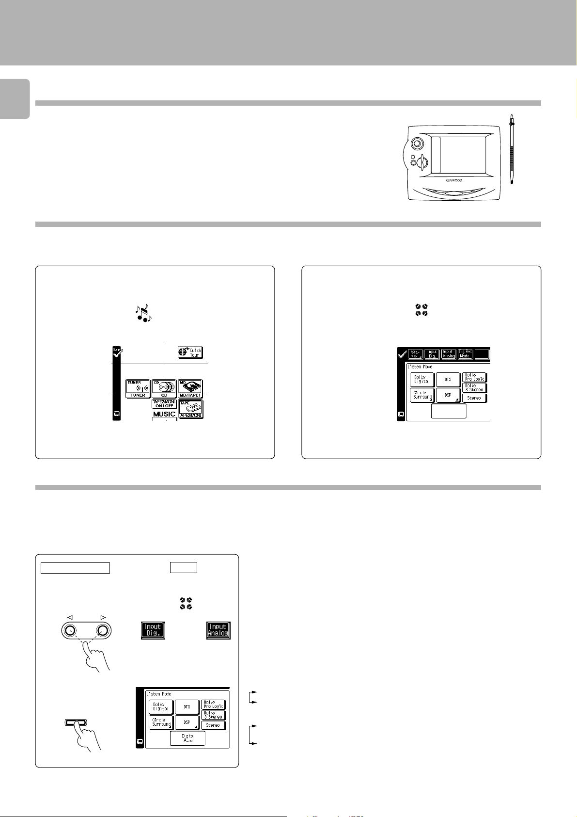
Operation examples
Switching the INPUT SELECTOR (Selecting the
Selecting the listen mode (select STEREO)
CD input)
1 Select the ”music“ icon in the Quick access menu.
s
u
i
c
m
2 Select the ”CD“ icon.
3 The input source is switched to ”CD“.
÷ Other input than CD can be selected in step 2.
÷ The icon of the registered component is displayed.
1Select the ”listen mode“ icon in the Quick access menu.
o
d
e
m
n
e
t
s
i
l
2Select the ”Stereo“ icon.
÷ It is also possible to select the Pro Logic, 3 STEREO icon in step
2.
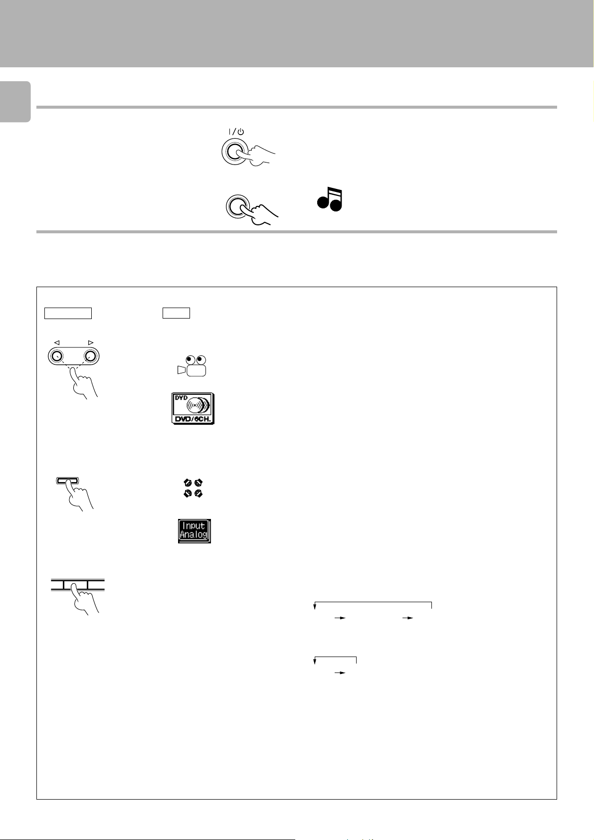
Input mode settings
CD and DVD inputs each include jacks for digital audio input and analog audio input.
You must select beforehand which type of input is to be used for each connected component. The initial factory setting is to use the digital audio signal
for playback.
To use the analog audio input for playback instead, you must set the input mode for the corresponding input to the analog mode.
After completing connections and turning on the AV control center, follow the steps below.
Digital input:
Main unit
1 Use the INPUT SE-
LECTOR key to select CD or DVD.
INPUT
GRC
m
n
e
t
s
i
l
or
o
d
e
Select this setting to play digital signals from a DVD, CD, or LD player.
Analog input:
Select this setting to play analog signals from CD,DVD.
Auto sound:
In the auto sound mode (AUTO SOUND indicator lights), the AV control center selects
the listening mode automatically during playback to match the type of input signal (Dolby
Digital, PCM, DTS ) and the speaker setting. The initial factory setting is auto sound on.
To keep the receiver set to the currently selected listening mode, use the INPUT MODE
key to select “DIGITAL MANUAL” (manual sound). However, even when this setting is
selected, there may be cases in which the listening mode is selected automatically to
match a Dolby Digital source signal depending on the combination of listening mode and
source signal.
Each press switches the setting as follows:
In DTS play mode
2 Press the INPUT
MODE key.
INPUT MODE
1 DIGITAL AUTO (digital input, auto sound)
2 DIGITAL MANUAL (digital input, manual sound)
In other mode than DTS play mode
1 DIGITAL AUTO (digital input, auto sound)
2 DIGITAL MANUAL (digital input, manual sound)
3 ANALOG (analog input, manual sound)
÷ With DIGITAL MANUAL, the audio may sometimes be not output when the signal
is switched.
Page 19
Remote control of components from the GRC
ENTER
V
O
L
U
M
E
UP
DOWN
CONFIRM
ON/STANDBYCONTRAST BACKLIGHT
Controlling the components connected through system control cords
When a CD player, MD recorder, cassette deck and/or DVD
player are connected with the AV CONTROL CENTER through
system control cords, their system control operations are
possible from the GRC.
Preparations
Select the “music” icon in the Quick access menu.
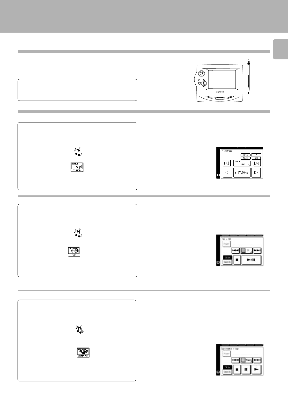
Operating the tuner
1 Select the ”music“ icon in the fixed segment screen.
(Select the icon)
2 Select the ”TUNER“ icon
Display the tuner operation menu.
3 Select the icon to be operated.
÷ System control connection 8
÷ Setup of source components%
s
u
i
c
m
÷ Any of the keys which can control the tuner can be selected.
19
Operating the CD player
1 Select the ”music“ icon in the fixed segment screen.
(Select the icon)
2 Select the ”CD“ icon.
Display the CD operation menu.
3 Select the icon to be operated.
s
u
i
c
m
Operating the MD recorder
1 Select the ”music“ icon in the fixed segment screen.
(Select the icon)
2 Select the ”MD/TAPE 1“ icon.
s
u
i
c
m
÷ The illustration shows the single CD operation menu.
÷ Any of the CD player operation keys can be selected.
÷ For the operation of the CD player, also read the instruction manual of
the CD player.
÷ Any of the MD recorder operation keys can be selected.
÷ For the operation of the MD recorder, also read the instruction manual
of the MD recorder.
Display the MD recorder operation menu.
3 Select the icon to be operated.
Page 20
20
Remote control of components from the GRC
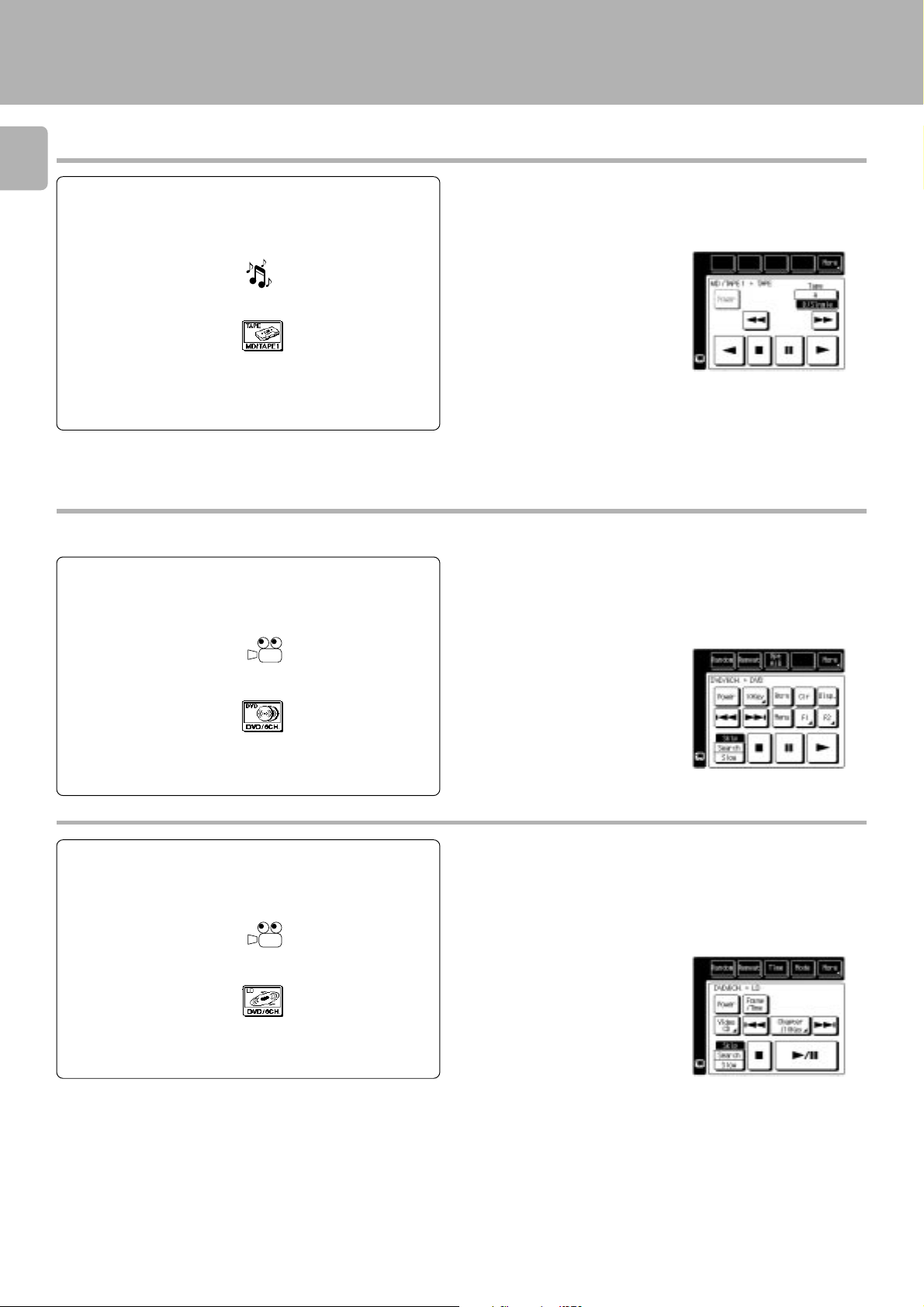
Operating the cassette deck
1 Select the ”music“ icon in the fixed segment screen.
(Select the icon)
2 Select the ”MD/TAPE 1“ icon.
Display the cassette deck operation menu.
3 Select the icon to be operated.
s
u
i
c
m
÷ Any of the cassette deck operation keys can be selected.
÷ For the operation of the cassette deck, also read the instruction manual
Select the ”movie“ icon in the Quick access menu.
Operating the DVD player
1 Select the ”movie“ icon in the fixed segment screen.
(Select the icon)
e
i
v
o
m
÷ Any of the DVD player operation keys can be selected.
÷ For the operation of the DVD player, also read the instruction manual
of the cassette deck.
of the DVD player.
2 Select the ”DVD/6CH.“ icon.
Display the DVD player operation menu.
3 Select the icon to be operated.
Operating the LD player
1 Select the ”movie“ icon in the fixed segment screen.
(Select the icon)
2 Select the ”LD“ icon.
Display the LD player operation menu.
3 Select the icon to be operated.
e
i
v
o
m
÷ Any of the LD player operation keys can be selected.
÷ For the operation of the LD player, also read the instruction manual of
the LD player.
Page 21

Remote control of components from the GRC
Controlling the other components
Operating the Video cassette recorder
1 Select the ”movie“ icon in the fixed segment screen.
(Select the icon)
2 Select the ”VIDEO 1“ icon.
Display the Video cassette recorder operation menu.
3 Select the icon to be operatwed.
e
i
v
o
m
Examples of component operation menus
The operation menus are variable depending on the connected components.
Operating the LD
÷ Any of the Video operation keys can be selected.
÷ For the operation of the Video cassette recorder, also read the
instruction manual of the Video cassette recorder.
21
Operating the TV
Operating the CABLE
Operating the SATELLITE
Operating the LD player (Non Kenwood)
Page 22

Convenient functions
22
Remote control of components from the GRC
One-touch operation features
(Main unit only)
(CD player, cassette deck (Single deck only), DVD player)
When the system is in standby mode, the operations as described below are possible provided that the associated components are connected through system control cords.
Preparations
1 Ensure that system control cords are connected.
2 Load the source component with the software to be played.
3 Press the
CENTER to put it to standby mode.
(ON/STANDBY) key of the AV CONTROL
Function available with the play key operation
1 Press the play key.
2 The system is switched from standby mode to ON mode.
3 The input selector is switched automatically.
4 Playback starts.
÷ The STANDBY indicator lights in the STANDBY mode.
÷ CD player and cassette deck.
Easy operation feature
The operations as described below are possible provided that
the associated components are connected through system control cords.
Operation available by switching the input
selector
1 Select the desired input with the input selector.
2 The selected source component starts to play.
÷ Turn on the system before switching the input selector.
÷ Select the source component with the INPUT SELECTOR.
Page 23

Speaker settings
Speaker settings
Setup for surround play (SET UP)
The feeling of presence in the surround effects can be improved by
performing the following adjustment procedure according to the speaker
system and listening room environment in use.
Once they are adjusted, re-adjustment is not necessary even after the
surround mode is switched to other modes.
When the SERIES 21 speakers are used, the settings in steps 1 and 2 are
not necessary.
Select the speaker setup mode
Select the speaker setup mode.
1
GRC
1 Select the “music” or “movie” icon in
the fixed segment screen.
e
s
u
i
c
m
2 Select the “Main” icon .
or
i
v
o
m
23
3 Enter the setup mode.
(Select the icon)
4 Select “SP Selection” icon.
5 Select “Quick” or “Custom” icon.
or
6 Select the item to be adjusted.
(Select the icon)
1 Quick Setup : Use this method for a simplified setup where
you identify whether a speaker is present and
let the receiver automatically determine the
appropriate speaker settings.
2 Custom Setup : Use this method for a more customized setup
where you determine more of the speaker
settings, such as the bandwidth of the sound
sent to each speaker.
Main unit
Each press of the SETUP key switches the adjustment items as
shown below. Each press MULTI CONTROL LEVEL
key switches the indication.
“SUBW” ................................. Sub-woofer ON/OFF setting.
“REMIX”*1 ............................. Sub-woofer remix ON/OFF
setting.
“FRNT”*2 ............................... Front speaker setting.
“CNTR” ................................... Center speaker setting.
“SURR” .................................. Surround speaker setting.
TEST TONE ............................ Test tone output.
FRONT DISTANCE ................. Front speaker distance.
CENTER DISTANCE ............... Center speaker distance.
SURROUND DISTANCE ........ Surround speaker distance.
End of SET UP
*1, *2 This setting is not available if “SW Off” is selected in the above.
÷ After adjusting the speaker size and ON/OFF setting, be sure to
perform “Adjust the speaker level”
described in step 4.
∞ using the test tone
or
Page 24

24
Select a speaker system.
2
1 Set up the subwoofer. “SW”
2 Select On or Off.
3 Set up the subwoofer remix. “Remix”
GRC GRC
(Select the icon)
Each press changes the setup.
(Select the icon)
Speaker settings
Quick setup
SW Yes : Subwoofer on
SW No : Subwoofer off
Custom setup
SW On : Subwoofer on
SW Off : Subwoofer off
÷ When the setting "SW Off" is selected, the front speakers automati-
cally are set to "Lrg" and the procedure skips to step 7.
SW Remix On : Subwoofer remix on
SW Remix Off : Subwoofer remix off
4 Select On or Off.
Each press changes the setup.
5 Set up the front speaker size. “FRNT (L/
R)”
(Select the icon)
or
6 Select Nml or Lrg.
Each press changes the setup.
7 Set the center speaker size. “CNTR (C)”
(Select the icon)
8 Select Lrg, Nml or Off.
9 Set the surround speaker size.“SURR (LS/
RS)”
(Select the icon)
or
0 Select Lrg, Nml or Off.
! Select the “Enter” icon.
÷ This setting is not available if “SW Off” is selected in the above.
÷ Only the Custom setup can be set.
÷ If you selected “On” for the subwoofer, all of the bass below 80Hz
is removed from other speakers in your system and is sent to the
subwoofer in all listening modes.
L/R Nml (normal)
: Average size front speakers are connected to the AV control
center.
L/R Lrg (large)
: Large front speakers are connected to the AV control center.
÷ When “SW” is set to ON and “L/R” is set to “Nml”, “C” and “LS/RS”
are set to automatically “Nml”.
C Lrg : A large center speaker is connected to the AV
control center.
C Nml : An average size center speaker is connected to the
AV control center.
C Off : No center speaker is connected to the AV control
center.
÷ When “SW” is set to ON and “L/R” is set to “Nml”, “C” and “LS/RS”
are set to automatically “Nml”.
÷ When “C” is set to “Nml” or Off, “LS/RS” is automatically set to
“Nml” or Off.
LS/RS Lrg : Large surround speakers are connected to the AV
control center.
LS/RS Nml : Average size surround speakers are connected to
the AV control center.
LS/RS Off : No surround speakers are connected to the AV
control center.
@ Select the “Next” icon.
Page 25

Set the speaker distance.
3
Speaker settings
25
GRC
1 Measure the distance from the listening
position to each of the speakers.
2 Select a speaker distance.
(Select the icon)
3 Set “SP Distance”.
(Select the icon)
To decrease
4 Touch to select the speaker.
5 Repeat steps 3 and 4 for each speaker.
6 Press the “Next” icon.
(Select the icon)
To increase
Jot down the distance from the listening position to each of
the speakers
FRONT (L/R) : meter(s)
CENTER (C) : meter(s)
SURROUND (LS/RS) : meter(s)
Speaker distance
DIGITAL REC
AUTO SOUND
DIGITAL REC
DIGITAL CS
DTS DOLBY
PRO LOGIC
DOWN MIX
1)F
÷ The allowable setting range is 1 to 30 feet (0.3 to 9.0 m), adjustable in 1
foot (0.3 m) increments.
÷ The speakers you selected appear on the display. Confirm that all the
speakers have been correctly selected.
T
3.)M
MHz SLEEP
KHz TIMER 1 2
3 STEREO
TAPE2/MONI.
L
LFE SW
LS
C
R
S
RS
Adjust the speaker level.
4
1 Select a speaker level.
2 Select "Test Tone" icon.
GRC
(Select the icon)
(Select the icon)
÷ The test tone which sounds like noise move across speakers in the
following sequence about 2 seconds.
TEST Lch (Front speaker, Left)
TEST Cch (Center speaker)
TEST Rch (Front speaker, Right)
TEST RSch (Surround speaker, Right)
TEST LSch (Surround speaker, Left)
TEST SWch (Subwoofer)
÷ Even when “Test Tone” is “Off”, it is possible to select the speaker
with the
or icon and adjust its level with the or icon.
Continued to next page
Page 26

26
2
T
O
S
D
GRC
3 Adjust the levels of all the speakers than
the front speakers (left, right).
While test tone is output from a speaker,
adjust the volume level of the speaker.
(Select the icon)
Speaker settings
÷ The test tones is not output from the speaker which has been set to
off. "Speaker settings"
FM
AM
MW
LW
Cch+1)dB
£
AUTO SOUND
DTS DOLBY
PRO LOGIC
MHz SLEEP
KHz TIMER 1
To decrease
level
4 Repeat 3 until all the system's speakers
(except the subwoofer) play at the same
volume.
5 Press the “Test Tone” icon.
(Select the icon)
Adjust the input level. (analog sources only)
5
GRC
1 Select the “music” or “movie” icon in
the fixed segment screen.
s
u
i
c
m
or
2 Select the “Main” icon .
3 Enter the SETUP mode.
(Select the icon)
To increase
level
e
i
v
o
m
Display when test tone is output from a surround speaker
÷ Be sure to adjust from the listening position.
÷ Each press of the key increases or decrease the level by 1 dB.
÷ To set the subwoofer level, listen to familiar music or films that have
strong bass content and adjust the subwoofer level until it sounds
balanced with the rest of the speakers.
÷ When the volume level is increased during the “Test Tone” operation
and it is finished while the volume level is high, the increased volume
level will be maintained.
If the input level of an analog source signal is too high or the AV control
center’s CLIP indicator lights, adjust the input level.
AUTO STEREO
FM
MEMO.
TUNED
AM
RDS
TP
EON
MW
PTY TA NEWS
LW
CLIP
10F
MUTE
T
4.5
4 Select the “Input” icon.
(Select the icon)
5 Select the “Attenuation” icon.
(Select the icon)
To quit the SETUP mode
If the CLIP indicator lights with analog input, set the input level to -3
or -6 dB to avoid sound distortion.
÷ This adjustment is not available with DVD 6ch INPUT.
÷ This adjustment is not available when the input mode is DIGITAL.
÷ The selected input level can be stored in memory on a per-selector
basis.
Input level
O STEREO
FM
O.
TUNED
AM
TP
EON
MW
TA NEWS
LW
INPUT 6
E
CLIP
Each press changes the level.
1 0 dB
2 -3 dB
3 -6 dB
GRC
Press the icon.
_
AUTO
DTS
PRO L
MHz
KHz
Page 27

Playing music
KHz TIMER 1 2
TAPE2/M
FM
LW
MW
AUTO SOUND
TUNED
EON
TP
CLIP
PRO LOGIC
DIGITAL
3 ST
AM
MHz SLEEP
DOWN
DIGITAL
DTS DOLBY
DIGITAL
VOL
_
5
)
d
B
The following procedure allows to play a MD,CD or cassette
tape.
Preparations
÷ Connect components as described in “System connection”.
÷ Complete “Setup of the Graphical Remote Control (GRC)
unit”.
Press the ON/STANDBY key to ON.
1
5
@
Sound adjustment
27
Main unit
ON/STANDBY
Select the input source.
2
Main unit
INPUT
÷ Step 3 can be omitted if the easy operation feature is available.
“Easy operation feature”
Play the selected source.
3
Main unit
Operation on each
source component
GRC
GRC
(Select the icon)
s
u
m
or
GRC
(Select the icon)
CD
ON/STANDBY
i
c
MD
or
™
÷ Load the CD player or cassette deck with the software to be played.
\Read the instruction manuals of the associated components.
With the main unit operation, the input sources are switched as shown below.
1 TUNER (frequency display)
2 CD
3 MD/TAPE 1
4 DVD/DVD 6ch INPUT *1
5 VIDEO 1
6 VIDEO 2
Pressing and holding the AUTO key for more than 2
seconds allows the source to be switched as shown
below.
*1: To change the DVD display to DVD 6ch INPUT or LD
display
To enable system-control operation, the displayed information should
be set according to the actually connected components.
The selected source is displayed.
AUTO STEREO
FM
MEMO.
TUNED
AM
RDS
TP
EON
MW
PTY TA NEWS
CLIP
MUTE
DC
LW
0
Adjust the volume.
4
Main unit
VOLUME CONTROL
DOWN
To
decrease
volume
UP
To
increase
volume
GRC
U
L
O
V
DOWN
Volume level is displayed.
UP
E
M
To increase volume
To decrease volume
÷ Rotating the VOLUME CONTROL at a higher speed increases the
amount of volume change (AI VOLUME function).
÷ The sound of input source cannot be listened to while TAPE 2/
MONITOR is ON.
•
Page 28

28
FM
LW
MW
AUTO STEREO
MEMO.
TUNED
MUTE
RDS
EON
TP
PTY TA NEWS
CLIP
AM
To listen through headphones
Sound adjustment
Playing music
1 Plug headphones.
PHONES
2 Adjust the volume.
L
O
V
DOWN
U
E
M
GRC
UP
Main unit
VOLUME CONTROL
DOWN
To
decrease
volume
UP
To
increase
volume
To mute sound temporarily
÷ The speaker sound is defeated at the moment headphones are
inserted into the PHONES jack.
÷ If headphones are plugged in during surround play, its mode is
automatically switched to the STEREO mode.
If they are plugged in during DVD 6ch INPUT play, only the front L ch
and R ch will be played.
The previous status resumes at the moment headphones are unplugged.
÷ If headphones are plugged in during test tone output, the test tone
output stops.
To increase volume
To decrease volume
Main unit
GRC
MUTE
Blinks
To cancel
Press the MUTE key again.
Notes for using the CD, DVD or DVD 6ch INPUT source
When CD, DVD or DVD 6ch INPUT is selected as the input source, the operation is subjected to the following restrictions.
Restrictions with CD and DVD:
1. When the input is a digital signal, the TAPE2/MONITOR function cannot be used.
Restrictions with DVD 6ch INPUT (except with the ANALOG input) :
1. The monitor function cannot be activated by pressing the TAPE 2/MONITOR key.
2. The Listen mode operations are not available.
÷ The speaker setting is not available with DVD 6ch INPUT.
÷ The sound adjustment is not available with DVD 6ch INPUT.
÷ When DVD 6ch INPUT is selected, all the speaker levels become 0 dB so the levels should be set on the source component.
Regarding TAPE 2/MONITOR
A cassette deck or graphic equalizer can be connected to this unit’s TAPE 2/MONITOR terminals. If you connect a graphic equalizer, turn the
TAPE 2/MONITOR key ON. If you connect a 3-head cassette deck, you can monitor the source sound, or the sound being recorded, while recording.
Pressing the TAPE 2/MONITOR key lets you compare the recorded sound and the source sound. Refer to the operating manual for the component you
connected for further details.
Page 29

A
L
G
G
G
G
G
Sound adjustment
Sound adjustment
29
Ajustment for surround play
Adjusting the tone (Stereo status only)
1
GRC
1 Enter the SOUND adjustment mode.
(Select the icon)
2 Select the "Tone" icon.
(Select the icon)
To decrease
3 Touch to turn the tone setting on or
off.
This adjustment is possible only when the
PCM or Analog input is used and the listen
mode is set to STEREO.
4 Touch the left
next to a tone setting (treble or bass) to
adjust it. A readout
arrows shows the current setting.
d
n
u
o
s
or right arrow
To increase
between the
(while listening to music) (SOUND)
Main unit
Each press of the SOUND key switches the indication.
1 BASS : Tone, Bass
2 TREBLE : Tone, Treble
3 C : Center speaker
4 LS/RS : Surround speaker, Left/Right
5 SW : Sub woofer
6 MIDNIGHT
÷ Adjustments 1 and 2 are not available in other modes than STEREO
and “Tone” is set to “On”.
÷ Adjustments 3, 4 and 5 are available only when the corresponding
speakers are set.
÷ The tone adjustment is not available with DVD 6ch INPUT.
÷ With the GRC, the adjustment items shown in a single menu can be
adjusted at once. (The adjustment steps 1, 2 are provided in a single
menu so they can be adjusted successively without changing the
menu screen.)
÷ 6 is available only with the Digital input.
The display on the GRC disappears if no operation on the GRC
has been pressed for about 7 seconds.
Note
NoteNote
M
M
M
M
W
W
WLW
BAss
÷ The level can be adjusted between -10 and +10 in step of 2.
EREO
FM
NED
AM
TP
MW
EWS
LW
TREB +2
IP
÷ The level can be adjusted between -10 and +10 in step of 2.
Bass tone level
_
Treble tone level
2
•
AUTO SOUND
DTS DOLBY
PRO LOGIC
MHz SLEEP
KHz TIMER 1 2
AUTO SOUND
DTS DOLBY
PRO LOGIC
MHz SLEEP
KHz TIMER 1 2
DI
DI
DI
DI
DIG DI
D
TAT
Adjust the volume levels for the speakers. (In other modes than stereo)
2
1 Select the "SP Level" icon.
(Select the icon)
To increase
To decrease
÷ This adjustment is not available when DVD 6ch INPUT is selected.
Continued to next page
Page 30

30
T
D
D
D
2
T
KHz TIMER 1 2
FM
LW
MW
AUTO SOUND
TP
PRO LOGIC
AM
MHz SLEEP
DTS DOLBY
s
W +1
)
Sound adjustment
2 Adjust the center speaker level. “C”
(Select the icon)
3 Adjust to the desired level by pressing
keys
and
4 Adjust the surround speaker level. “LS/
RS”
(Select the icon)
or
5 Adjust to the desired level by pressing
keys
and
6 Adjust the subwoofer level. “SW”
(Select the icon)
Main unit
center speaker level
EREO
FM
UNED
AM
TP
MW
NEWS
LW
Cch +2
LIP
÷ The level can be adjusted between -10 and +10 in step of 1.
Surround speaker level
EREO
FM
UNED
AM
TP
MW
EWS
LW
s+1/+1
LIP
÷ The level can be adjusted between -10 and +10 in step of 1.
Sub woofer level
AUTO SOUND
DTS DOLBY
PRO LOGIC
MHz SLEEP
KHz TIMER 1
AUTO SOUND
DTS DOLBY
PRO LOGIC
MHz SLEEP
KHz TIMER 1 2
7 Adjust to the desired level by pressing
keys
MIDNIGHT function
1 Select the “Midnight” icon.
2 Select the MIDNIGHT mode.
and
÷ The level can be adjusted between -10 and +10 in steps of 1.
÷ The volume levels adjusted here are just temporary; they return to the
levels originally set in the setup operation when the power is turned off,
the input selector is switched or the setup operation is started.
MIDNIGHT function
Any time you don't want to experience the loud and soft volume extremes
of recorded sound (for example, late at night), use MIDNIGHT function to
reduce volume extremes. This feature keeps loud, dramatic sound from
being too loud (perhaps disturbing family members or neighbors) while
ensuring that you can still hear whispered dialog or other soft sounds.
Midnight function only works if you are listening to a Dolby Digital program
that has been encorded with special compression data.
Each press changes the mode.
1 1 ... For quieter balancing.
2 2 ... For quietest balancing (the least difference between the
loudest and quietest sound).
3 OFF
Page 31

Recording
When recording sound with a recorder component of
KENWOOD, synchro recording is possible by setting the
INPUT SELECTOR to select MD or TAPE 1 according to the
connected component.
Sound may not be reproduced when the input signal and
LISTEN MODE are selected improperly.
How to select the digital input, analog input and LISTEN
MODE.
Recording an analog input source
To record a music source
1
Main unit
1 Select the ”edit“ icon in the fixed seg-
ment screen.
(Select the icon)
2 Select the source to be recorded.
Select an input source other than MD/TAPE 1.
INPUT
GRC
t
i
d
e
E
Each press switches the indication.
Select the icon of the source to be played.
Recording
31
Main unit
1 TUNER (Frequency display)
2 CD
3 MD/TAPE 1
4 DVD/DVD 6ch INPUT
5 VIDEO 1
6 VIDEO 2
GRC
3 Select the “Distination”.
4 Press the “Src.” icon.
÷ For the recording using a cassette deck or MD recorder, read the
instruction manual of the cassette deck or MD recorder.
Continued to next page
Page 32

32
Select the ANALOG input mode.
2
Main unit
INPUT MODE
Start recording.
3
1 Set the input mode to ANALOG.
(Select the icon)
GRC
Recording
Main unit
Each press switches the indication.
1 DIGITAL AUTO
2 DIGITAL MANUAL
3 ANALOG
GRC
Select the icon of the source to be played.
÷ The switching is not available when the DVD 6ch INPUT is selected.
÷ “3 ANALOG” cannot be selected when the input signal is the DTS
signal.
÷ Each press of
and “Destination” alternately.
÷ The input mode cannot be changed during recording.
÷ Setting 1 is not necessary unless when the CD or DVD source is
selected.
or switches the display between “Source”
•
Main unit
GRC
1 Play the source to be recorded.
2 Press the “Dst.” icon.
3 Press the record key to enter record-pause
mode.
4 Press the “Src.” icon.
5 Pause the playing the source from begin-
ning of the track being recorded.
6 Play the source and start recording.
÷ The synchro recording function is not available when the playback
source is the DVD player.
Page 33

Recording
When recording sound with a recorder component of
KENWOOD, synchro recording is possible by setting the
INPUT SELECTOR to select MD or TAPE 1 according to the
connected component.
Sound may not be reproduced when the input signal and
LISTEN MODE are selected improperly.
How to select the digital input, analog input and LISTEN
MODE.
E
Recording a digital input source (CD,DVD)
To record a music source
1
Main unit
INPUT
GRC
1 Select the ”edit“ icon in the fixed seg-
ment screen.
(Select the icon)
t
i
d
e
2 Select the source to be recorded.
Select an input source other than MD/TAPE 1.
Main unit
Each press switches the indication.
1 TUNER (Frequency display)
2 CD
3 MD/TAPE 1
4 DVD/DVD 6ch
5 VIDEO 1
6 VIDEO 2
GRC
Select the icon of the source to be played.
33
3 Select the “Distination”.
4 Press the “Src.” icon.
÷ For the recording using a cassette deck or MD recorder, read the
instruction manual of the MD recorder or cassette deck.
Continued to next page
Page 34

34
Set the input mode to DIGITAL AUTO (MANUAL).
2
Recording
Main unit
INPUT MODE
Select the DIGITAL REC mode.
3
AUTO REC MODE
Main unit
DIGITAL
REC
MANUAL REC MODE
Main unit
1 Set the input mode to “DIGITAL AUTO
(MANUAL)”.
(Select the icon)
1 Set the REC mode to “AUTO REC
MODE”.
2 Put the cassette deck (MD recorder) in
record-pause mode.
Method 1
DIGITAL
REC
1 Play the source to be recorded.
2 Set the input mode to “MANUAL REC
MODE”.
3 Apply decoding that matches the input
signal from the source selected and played
in “1” above.
Method 2
1 Set the input mode to “MANUAL REC
MODE”.
2 Play the source to be recorded.
3 If audio is not output, switch the decoder
by pressing the LISTEN MODE key.
GRC
Main unit
Each press switches the indication.
1 DIGITAL AUTO Input signal is detected automatically.
2 DIGITAL MANUAL Selected input signal is held.
3 ANALOG
GRC
1 DIGITAL AUTO Input signal is detected automatically.
2 DIGITAL MANUAL Selected input signal is held.
÷ The switching is not available when the DVD 6ch INPUT is selected.
•
÷ “3 ANALOG” cannot be selected when the input signal is the DTS
signal.
÷ Each press of
and “Destination” alternately.
Main unit
Each press switches the indication.
1 REC MODE OFF Off
2 AUTO REC MODE
3 MANUAL REC MODE
Switch on the REC MODE to record a digital input source.
Usually use the AUTO REC MODE to record audio input sources.
When the digital mode changes during recording in the AUTO
REC MODE, the audio may be interrupted momentarily. To
record the audio from the beginning of the digital mode change,
use the MANUAL REC MODE.
÷ The input is automatically down-mixed to 2 channels.
÷ Recording is not available when the DVD 6ch INPUT is selected.
÷ The EON overriding does not occur during recording.
÷ For the recording using a cassette deck or MD recorder, read the
instruction manual of the cassette deck or MD recorder.
÷ The LISTEN MODE key can be used to switch the decoder only when
the MANUAL REC MODE is selected.
÷ Sound may not be reproduced when the input signal and LISTEN
MODE are selected improperly.
How to select the digital input, analog input and LISTEN MODE.
or switches the display between “Source”
•
E
Continued to next page
Page 35

GRC
1 Select the ”edit“ icon in the fixed seg-
ment screen.
(Select the icon)
2 Select the source to be recorded.
Select an input source other than MD/TAPE 1.
t
i
d
e
Recording
GRC
Select the icon of the source to be played.
÷ For the recording using a cassette deck or MD recorder, read the
instruction manual of the MD recorder or cassette deck.
÷ The input is automatically down-mixed to 2 channels.
÷ Recording is not available when the DVD 6ch INPUT is selected.
•
35
3 Select the “Distination”.
4 Press the “Src.” icon.
5 Set the REC mode to “Dig. Rec Mode.”.
(Select the icon)
6 Play the source to be recorded.
GRC
1 REC MODE OFF Off
2 AUTO REC MODE
3 MANUAL REC MODE
Switch on the REC MODE to record a digital input source.
Usually use the AUTO REC MODE to record audio input sources.
When the digital mode changes during recording in the AUTO
REC MODE, the audio may be interrupted momentarily. To
record the audio from the beginning of the digital mode change,
use the MANUAL REC MODE.
7 Press the “Dst.” icon.
8 Press the record key to enter record-pause
mode.
÷ The switching is not available when the DVD 6ch INPUT is selected.
•
÷ 3 cannot be selected when the input signal is the DTS signal.
÷ Each press of
and “Destination” alternately.
÷ If audio is not output, switch the decoder by pressing the LISTEN MODE
key.
or switches the display between “Source”
Continued to next page
Page 36

36
Start recording.
4
Recording
Main unit
GRC
1 Press the “Src.” icon.
2 Pause the playing the source from begin-
ning of the track being recorded.
3 Play the source and start recording.
Page 37

Recording
37
Page 38

Listening to radio broadcasts
I
S
O
L
1
D
D
KHz TIMEKHz TIME
FM
LW
MW
AUTO SOUAUTO SOU
AUTO STEREO
MEMO.
TUNED
MUTE
RDS
EON
TP
PTY TA NEWS
CLIP
PRO LOGICPRO LOGIC
AM
MHz SLEEP
DTS DOLBDTS DOLB
__
89
))
Radio stations can be classified into RDS (Radio Data System) stations and other stations. For listening to RDS sta-
38
tions or storing RDS stations in preset memory, see section
entitled “Functions of RDS”.
Tuning radio stations
Select the TUNER input.
1
Main unit
INPUT
GRC
(Select the icon)
u
m
s
i
c
·
Main unit
Each press switches the indication.
1 TUNER (Frequency display)
2 CD
3 MD/TAPE 1
4 DVD/DVD 6ch
5 VIDEO 1
6 VIDEO 2
Listening to radio broadcasts
Frequency display
AUTO SAUTO
DTS DODTS D
PRO LOPRO L
89
.
))
MHz S
KHz TIKHz T
Select the broadcast band.
2
Main unit
TO BAND
Select the tuning method.
3
Main unit
A.MEMO
AUTO BAND
GRC
(Select the icon)
GRC
(Select the icon)
÷ The previously tuned frequency is displayed.
Main unit
Each press switches the indication.
1 FM
2 MW
3 LW
Each press switches the indication.
Main unit
1 AUTO lit (auto tuning)
2 AUTO not lit (manual tuning)
GRC
1 Auto (auto tuning)
2 Manual (manual tuning)
÷ Normally, set to "AUTO" (auto tuning). If the radio waves are weak and
there is a lot of interference, switch to manual tuning. (With manual
tuning, stereo broadcasts will be received in monaural.)
1 FM (Australia only)
2 AM (Australia only)
AUTO STEREO
FM
MEMO.
TUNED
RDS
EON
PTY TA NEWS
MUTE
CLIP
TP
Lights up
__
AM
MW
LW
89
AUTO STEREO
MEMO.
TUNED
RDS
TP
EON
PTY TA NEWS
CLIP
MUTE
Lights up
FM
AM
MW
LW
))
.
AUTO SOUN
AUTO SOUN
DTS DOLBY
PRO LOGIC
MHz SLEEP
KHz TIMER 1KHz TIMER
4
Select a station.
Main unit
PTY SELECT
TUNING
To decrease
frequency
To increase frequency
To decrease frequency
GRC
(Select the icon)
To increase frequency
Frequency display
“TUNED” lights up when a
station is tuned.
Auto tuning : The next station found is tuned automatically.
Manual tuning : Press and hold the key until the desired station is
received.
Page 39

Listening to radio broadcasts
T
L
T
L
M
O
G
L
E
T
L
Functions of RDS
(Radio Data System)
RDS is a system which transmits useful information (digital data) for FM broadcasts together with the broadcast signal. Tuners
and receivers designed for RDS reception can extract the information from the broadcast signal for use with various functions
such as automatic display of the station name.
Functions made possible with RDS
The RDS indicator lights up when an
RDS broadcast (signal) is received.
PTY (Program Type Identification) Search :
The tuner automatically searches for a station which is currently
broadcasting a specified program type (genre).
e
EON (Enhanced Other Network) reservation
By selecting one of the two kinds of program previously, the tuner
switches automatically to a station broadcasting that kind of program
whenever it starts broadcasting. When the broadcasting completes,
the tuner returns automatically to the originally-received station.
t
÷ Some functions may not be provided or be given different names
depending on countries or areas.
AUTO STEREO
MEMO.
TUNED
RDS
EON
PTY TA NEWS
CLIP
MUTE
FM
AM
TP
MW
LW
BBC
1FM
PS (Program Service Name) display : See figure 1 below.
When an RDS broadcast is received, the station name is automatically
displayed.
RT (Radio Text) display :See figure 2 below.
Some of the RDS stations also transmit text data.
When the RT display is selected with the RT key, the broadcast text
is scrolled on the display.
AUTO MEMORY
This function automatically selects the stations providing RDS and
FM broadcasting and stores them in the preset memory (up to 40
stations can be preset).
‚
Before using a function utilizing the RDS, be sure to
perform the AUTO MEMORY operation by referring to the
description in “Presetting RDS stations (AUTO MEMORY)”.
‚
39
AUTO AUTO
DTS DTS
PRO LPRO
MHz MHz
KHz TKHz
RDS DISPLAY key
Main unit
Pressing the RDS DISPLAY key
changes the display contents.
DISPLAY
RDS
GRC
(Select the icon)
Display mode priority ranking
When an FM broadcast is received :
1 PS (Program Service Name) display
2 RT (Radio Text) display
3 Frequency display
1 PS (Program Service Name) display :
When an RDS broadcast is received, the station name is automatically displayed.
If no PS data was sent, “NO PS” is displayed.
STEREO
AUTO
FM
MEMO.
TUNED
AM
RDS
TP
EON
MW
PTY TA NEWS
LW
BBC
CLIP
MUTE
1FM
2 RT (Radio Text) display:
Text accompanying RDS broadcast is scrolled on the display during
reception. “NO RT” is displayed if the received RDS station is not
accompanied with RT data.
Text is scrolled from the right to the left.
STEREO
AUTO
FM
MEMO.
TUNED
AM
RDS
TP
EON
MW
PTY TA NEWS
LW
MUTE
ABCDEFGH
CLIP
AUTO AUTO
DTS DTS
PRO LPRO
MHz MHz
KHz TKHz
AUTO
DTS
PRO
MHz
KHz
3 Frequency display :
The frequency of the current station is displayed.
)
AUTO S
DTS DO
PRO LO
MHz SL
KHz TI
STEREO
AUTO
FM
MEMO.
TUNED
__
AM
RDS
TP
EON
MW
PTY TA NEWS
LW
MUTE
CLIP
1)25
.
Page 40

Use the operating procedure on this page to store RDS stations
I
S
O
L
1
automatically in preset memory. Up to 40 RDS stations can be
40
preset and received with a simple key operation.
This unit is compatible with the RDS so it can use convenient
RDS functions including automatic tuning and EON reservation.
RDS stations should be stored in the preset memory following
the procedure in “Presetting RDS stations” before listening to
RDS stations.
Listening to radio broadcasts
Presetting RDS stations
(AUTO MEMORY)
The following procedure allows to select stations broadcasting RDS broadcast and store them in the preset memory (up to 40
stations can be preset).
Select the TUNER input.
1
Main unit
INPUT
Select the broadcast band “FM”.
2
Main unit
TO BAND
(Select the icon)
(Select the icon)
GRC
GRC
s
u
i
c
m
Main unit
Each press switches the indication.
1 TUNER (Frequency display)
2 CD
3 MD/TAPE 1
4 DVD/DVD 6ch INPUT
5 VIDEO 1
6 VIDEO 2
÷ The previously tuned frequency is displayed.
Main unit
Each press switches the indication.
1 FM
2 MW
3 LW
1 FM (Australia only)
2 AM (Australia only)
UTO STEREO
FM
EMO.
TUNED
DS
EON
TY TA NEWS
UTE
CLIP
TP
Lights up
__
AM
MW
LW
Frequency display
89
89
))
.
))
.
AUTO SAUTO
DTS DODTS D
PRO LOPRO L
MHz S
KHz TIKHz T
AUTO SOUND
DTS DOLBY
PRO LOGIC
MHz SLEEP
KHz TIMER 1KHz TIMER
Preset radio stations by AUTO MEMORY.
3
Main unit
Press the
A.MEMO key.
A.MEMO
AUTO
1 Perform step 1~4 of “Tuning radio sta-
tions”
2 Press the “Memo” key during receiving a
station.
3 Press the “Auto Memo” key.
In a few minutes, the stations with which
RDS broadcast is received are stored in
order beginning from preset channels
“01” (up to 40 stations can be preset).
If the number of stations with RDS
broadcasting is less than 40, non-RDS
FM stations will be preset after the
RDS stations.
GRC
(Select the icon)
(Select the icon)
°
DIGITAL REC
AUTO SOUND
AUTO STEREO
FM
MEMO.
TUNED
AM
RDS
TP
EON
MW
PTY TA NEWS
LW
AUTO )M1
CLIP
MUTE
| Scroll display “AUTO MEMORY“
÷ If stations have already been stored in preset channels, the same
number of these preset channels as the number of stations are
replaced with the data of the newly preset stations.
Number of preset stations
DTS DOLBY
PRO LOGIC
MHz SLEEP
KHz TIMER 1 2
DIGITAL REC
DIGITAL CS
3 STEREO
DOWN MIX
TAPE2/MONI.
L
LFE SW
LS
C
R
S
RS
Page 41

Listening to radio broadcasts
The AUTO MEMORY function gives precedence to RDS
stations and assigns them from preset number 1. Therefore,
when it is required to preset RDS stations as well as non-RDS
stations, execute the AUTO MEMORY operation first then
proceed to the manual memory operation of non-RDS stations.
Preparation
÷ Select the TUNER input. (
÷ Display the Tuner operation menu. (
Order of radio station presetting
Other stations than the RDS stations can be stored in the
preset memory by presetting them after the RDS stations
preset by AUTO MEMORY as shown below or overwriting the RDS stations preset in some preset numbers.
Preset number
1 2 39 40
1 AUTO MEMORY
RDS stations
(~ FM stations)
2 Manual memory
FM, MW or LW stations
~
FM, AM stations (Australia only)
Storing radio stations manually in preset memory
GRC
1 Perform step 1~4 of “Tuning radio sta-
tions”
2 Press the “Memo” icon during receiving
a station.
3 Select the preset channel for use in pre-
setting the station.
4 Press the “Enter” icon.
(Select the icon)
°
÷ Apart from the auto memory function, radio stations can also be stored
manually in the preset memory.
÷ It is also possible to assign a station name to the manually preset
station.
÷ Repeat steps 1,2,3,4 for each of the stations to be stored in
memory.
÷ If a station is stored in a preset number which has already stored a
station memory under it, the previous memory is replaced by the new
memory content.
÷ If RDS stations are stored manually in the preset memory, the PS may
not be included in the memory depending on receiving conditions.
41
5 Assigning a name to preset memory.
(Select the icon)
6 Select the preset channel to be named by
pressing
7 Press the “Name Input” icon to select the
name input mode.
(Select the icon)
8 Compose a name.
or .
To decresase
To incresase
÷ The name can be composed using up to 8 characters.
÷ Touch
access special characters (such as @, !, &, etc.). Touch it a third time
to return to uppercase characters.
÷ Touch
÷ Touch BS (Backspace) to clear the last caracter you entered. Touch
ALL DEL to delete all the characters in the line.
to access to lowercase characters. Touch it again to
or to move back and forth between the characters.
Continued to next page
Page 42

Listening to radio broadcasts
/
A
T
N
A
A
42
GRC
9 Press the “Enter” icon to enter in memory.
(Select the icon)
0 Press the “Enter” icon.
Receiving all preset stations in order
GRC
1 Select the preset number of the desired
station by pressing
(Select the icon)
or .
÷ To preset other stations, repeat 6 to 9 for each of them.
(P. CALL)
÷ Every time the key is pressed, the next station in the order of the preset
number is received.
When you press key, ...................................
2 1 3394038
The preset number
decreases.
The preset
number
increases.
Receiving a preset station
GRC
1 Press the preset call icon.
Preset call icon
2 Select the preset number of the desired
station by pressing
or .
When you press
key, ..................................
2 1 3394038
If the key is held pressed .............. Preset stations will be received suc-
Preset number stored in memory
STEREO
FM
.
TUNED
AM
TP
ON
MW
A NEWS
LW
15 89.
CLIP
÷ Enter the preset number (max. 40) of the desired radio station.
cessively for about half a second each.
DIGIT
AUTO SOUND
DIGIT
DIGIT
DTS DOLBY
PRO LOGIC
DOW
))
MHz SLEEP
KHz TIMER 1 2
3 S
TAPE2
3 Press the “Enter” icon.
(Select the icon)
To decresase
To incresase
Page 43

T
L
By specifying the type of program (genre) you want to listen
to, the tuner automatically searches for a station which is
currently broadcasting a program of the specified type.
With certain receiving conditions, it may take more than
1 minute until the search completes.
Listening to radio broadcasts
43
Preparation
÷ Preset RDS stations with the AUTO
MEMORY function.
‚
÷ Select the TUNER input. ‚
÷ Set the receiving band to FM. ‚
This step can be omitted if you have already executed the
Note
NoteNote
AUTO MEMORY procedure.
Searching for a desired program type
Select the PTY search mode.
1
Main unit
RDS
PTY
Select the desired program type.
2
(Select the icon)
Use program type table on the right for your convenience.
Main unit
1 When selecting with the
(Select the icon)
PTY SELECT
TUNING
Previous
program
type
Next
program
type
The or icon allows to select desired program types from the
29 types. Press and hold the icon and release it when the desired
type is displayed.
GRC
GRC
Previous
program
type
Select while “PTY” is lit.
or icons.
Next
program
type
When an RDS broadcast is received, the program type is shown on
the display. If no PTY data is available, or if the station is not an RDS
station, “NONE” is displayed.
Program type table
( )
DOWN
)
(
UP
(PTY search)
AUTO STEREO
FM
MEMO.
TUNED
AM
RDS
TP
EON
MW
PTY TA NEWS
LW
MUTE
Program Type Name Display
No program type or undefined NONE
Pop Music POP M
Rock Music ROCK M
Easy Listening Music EASY M
Light Classical LIGHT M
Serious Classical CLASSICS
Other Music OTHER M
News NEWS
Current Affairs AFFAIRS
Information INFO
Sport SPORT
Education EDUCATE
Drama DRAMA
Culture CULTURE
Science SCIENCE
Varied VARIED
Weather WEATHER
Finance FINANCE
Children’s programs CHILDREN
Social affairs SOCIAL
Religion RELIGION
Phone in PHONE IN
Travel TRAVEL
Leisure LEISURE
Jazz Music JAZZ
Country Music COUNTRY
National Music NATION M
Oldies Music OLDIES
Folk Music FOLK M
Documentary DOCUMENT
NEWs
CLIP
AUTO
DTS
PRO
MHz
KHz
Continued to next page
Page 44

44
T
L
T
L
Start the search.
3
Main unit
RDS
PTY
GRC
(Select the icon)
Listening to radio broadcasts
When searching for a Rock Music broadcast.
Display while the tuner is searching.
STEREO
AUTO
FM
MEMO.
TUNED
AM
RDS
TP
EON
MW
PTY TA NEWS
LW
OCK M
R
CLIP
MUTE
AUTO
DTS
PRO
MHz
KHz
To change to a different program type:
Repeat steps 1, 2, 3.
To cancel search in the middle of it
Main unit
RDS
PTY
(Select the icon)
GRC
Blinks
Program type name display.
When a station is received.
STEREO
AUTO
FM
MEMO.
TUNED
AM
RDS
TP
EON
MW
PTY TA NEWS
MUTE
Goes off
LW
CLIP
BBC
1FM
Station name display.
÷ If search is started while the program type is “NONE”, it turns
automatically into “POP M”.
÷ No sound is heard while “PTY” is blinking.
÷ If a program of the desired type cannot be found, “NO PROG” is
displayed, then after several seconds the display returns to the original
display.
÷ When a station with the selected program type is searched, its
reception starts and the type name display changes to the station name
display.
AUTO AUTO
DTS DTS
PRO LPRO
MHz MHz
KHz TKHz
Page 45

Listening to radio broadcasts
M
E
E
O
O
zMHz
When the receiver is tuned to a RDS EON station (a station at which the EON indicator lights up), this function lets you set the
receiver to automatically switch stations to receive news or traffic programs as they are broadcast. When the broadcast is over,
the receiver returns to the original station automatically.
45
Preparation
Note
Perform steps 1 to 3 of “Presetting RDS stations (AUTO
MEMORY)”.
‚
Note
÷ The EON function cannot be used if all of the 40 preset stations have
been stored using the procedure in “Storing radio stations manually
in preset memory”. Be sure to use the AUTO MEMORY function.
Reserving the desired information
Set the receiving band to FM.
1
Main unit
1 Select the Tuner input.
(Select the icon)
INPUT
2 Display the Tuner operation menu.
GRC
Each press switches the indication.
s
u
i
c
m
÷ The previously tuned frequency is displayed.
This step can be omitted if you have already executed the
AUTO MEMORY procedure.
(EON reservation)
Main unit
1 TUNER (Frequency display)
2 CD
3 MD/TAPE 1
4 DVD/DVD 6ch INPUT
5 VIDEO 1
6 VIDEO 2
Frequency display
89
))
.
q
AUTO SOUND
DTS DOLBY
PRO LOGIC
MHz SLEEP
KHz TIMER 1 2
DIGITAL DIGITAL
DIGITAL DIGITAL
DIGITAL DIGITAL
3 ST
3 ST
DOWN DOWN
TAPE2/MTAPE2/
TO BAND
3 Select the FM Band.
(Select the icon)
Tune to a preset RDS station.
2
Select a station with which the EON and
RDS indicators light.
(Select the icon)
PTY SELECT
TUNING
GRC
Each press switches the indication.
1 FM
2 MW
3 LW
÷ Radio stations can also be selected by pressing the
÷ If you want to reserve TA, receive a station with which the TP indicator
lights.
÷ When “EON” does not light although an RDS station is received, that
station is not transmitting EON data. Please select a different station.
1 FM (Australia only)
2 AM (Australia only)
TO STEREO
FM
EMO.
TUNED
S
TP
EON
Y TA NEWS
UTE
CLIP
Lights up
Display when “TA” is selected
AUTO STEREO
FM
MEMO.
TUNED
AM
RDS
TP
EON
MW
PTY TA NEWS
LW
CLIP
MUTE
__
AM
MW
LW
BBC
8900
.
or key.
1FM
AUT
AUT
DTS DTS
PRO PRO
MH
KHz KHz
TP (Traffic Program) indication
When the “TP” indicator is lit, this means that the presently-received station or a station in the same network is transmitting traffic information. When
“TP” is displayed for the station being received, the traffic information of this station can be received without EON reservation.
Continued to next page
Page 46

46
M
O
O
Select the desired kind of program.
3
Main unit
RDS
TA/NEWS
Wait for a reserved reception to start.
4
Leave the station with which the EON and RDS indicators light
tuned in. The tuner stands by for the reception provided that the
power is left ON.
If the “EON” indicator does not light in steps 3 and 4 and the
desired kind of information has already been selected, the information from only the station being received will be waited for.
GRC
(Select the icon)
Listening to radio broadcasts
Display when “TA” is selected
STEREO
AUTO
FM
MEMO.
TUNED
AM
RDS
TP
EON
MW
PTY TA NEWS
LW
BBC
CLIP
MUTE
“TP” lights for stations where TP (Traffic
Program) can be received.
Each press switches the indication.
1 TA (Traffic Announcement)
2 NEWS (News)
3 TA/NEWS
4 OFF (EON reservation cancelled)
÷ “NO DATA” is displayed if this operation is attempted before perform-
ing the AUTO MEMORY operation.
To keep listening to a tuner station:
Receive a station with which the “EON” and “RDS” indicators light.
To listen to other source than tuner:
1 While keeping the tuner tuned into a station with which the “EON”
and “RDS” indicators light, select the desired source with the
INPUT SELECTOR.
2 Even when the INPUT SELECTOR is set to other source than
TUNER, it is switched automatically to TUNER when EON-re-
served broadcast starts.
In this period, the source pauses if the source selected in 1 is CD
or MD, or stops if it is TAPE.
3 When the EON-reserved reception completes, the INPUT SELEC-
TOR returns to the previous input source.
÷ The EON overriding does not occur during recording.
÷ When the unit is in STANDBY mode, the EON function does not operate.
÷ When the transmission of the selected program contents ends in case
of automatic reception with the EON function, return will be made to
the status directly before operation of the EON function.
FM2
‚
AUT
AUT
DTS DTS
PRO PRO
MHz MHz
KHz KHz
To cancel EON reservation
Main unit
RDS
TA/NEWS
Turn the “TA”, “NEWS” indicators off.
GRC
(Select the icon)
Each press switches the indication.
1 TA
2 NEWS
3 TA/NEWS
4 OFF
STEREO
AUTO
FM
MEMO.
TUNED
AM
RDS
TP
EON
MW
PTY TA NEWS
LW
BBC
CLIP
MUTE
Should be OFF.
1F
Page 47

Listening to radio broadcasts
47
Page 48

Ambience effects
TV
Listening to radio broadcasts
This AV CONTROL CENTER incorporates 7 different sound modes to let you enjoy surround sound with a wide variety of
program sources. The Dolby Digital (AC-3) and Dolby Pro Logic surround sound let you enjoy theater-like surround effects when
48
you play Dolby Digital (AC-3) and Dolby Surround program sources (like Laserdiscs and DVDs). Dolby 3 Stereo creates a
panoramic frontal sound field. The Digital Signal Processing (DSP) modes let you create a variety of different sonic
environments from almost any type of program source.
To obtain the best possible surround sound, be sure to complete "Setup for surround play (SET UP)" before using the surround
modes.
Surround modes
£
DTS
The DTS multi-channel audio format is available on CD, LD and DVD
software. DTS is a strictly digital format and can not be decoded inside
most CD, LD or DVD players. For this reason, if you attempt to listen
to DTS encoded software through the analog output of your CD, LD
or DVD player, you will experience digital noise in most cases. This
noise can be quite loud if the analog output is connected directly to a
high power amplification system. Proper measures for playing the
digital output as described below should be taken to avoid this
situation. To enjoy DTS Digital Surround playback, an external 5.1
channel DTS Digital Surround decoder system or an amplifier with a
built-in DTS Digital Surround decoder must be connected to the digital
output (S/P DIF, AES/EBU or TosLink) of a CD, LD or DVD player.
SRS Circle Surround
The Circle Surround System was developed to provide the highest
level of sonic performance available in a Matrix system. Audio for
music was not the focus for other multichannel formats and, as a
result, there is a serious compromise in the performance of these
systems. That is not to say that the Circle Surround system is only for
music–other applications such as Cinema, Home Theater, multichannel broadcast, video tape and any other type of audio delivery can take
advantage of the superior performance of Circle Surround. Since
Circle Surround provides proper performance for music, the sonic
impact for all other applications is also improved. Circle Surround 5.1
is capable of delivering true five-channel impact.
Center speaker
Subwoofer
Front speaker
Surround speakers (stereo signal)
* Optional in this mode.
Center speaker
Subwoofer
Front speaker
Surround speaker (stereo signal)
Dolby Digital (AC-3)
The Dolby Digital (AC-3) surround format lets you enjoy up to 5.1
channels of digital surround sound from Dolby Digital (AC-3) program
sources (such as Laserdisc software marked
with previous Dolby surround, Dolby Digital (AC-3) provides even
better sound quality, greater spatial accuracy, and improved dynamic
range.
Note
Although a full set of speakers (front left, right, and center, Surround
left and right, and a subwoofer) is required for true 5.1 channel Dolby
Digital (AC-3) surround sound, this AV CONTROL CENTER lets you
enjoy Dolby Digital (AC-3) (and Dolby Pro Logic) program sources,
even if you connect only the front speakers.
DIGITAL
). Compared
Center speaker
Subwoofer (LFE)*
Front speaker
Surround speaker (stereo signal)
* LFE = Low Frequency Effects. This channel delivers separate non-
directional bass signals to the subwoofer for more dynamic deep
bass sound effects.
Although only Dolby Digital (AC-3) soundtracks incorporate a separate low frequency channel, connecting a subwoofer will also
improve deep bass performance in the other surround modes.
Page 49

TV
Dolby Pro Logic
TV
TV
Dolby Pro Logic is a specially encoded 2 channel surround format designed to provide theaterlike surround sound from Dolby Surround encoded sources (such as video and Laserdisc
software marked
Pro Logic surround decoder to let you enjoy the wide variety of currently available Dolby
Surround home video software.
). This AV CONTROL CENTER is equipped with a Dolby
Listening to radio broadcasts
Subwoofer*
Front Speaker
Surround speaker
* Optional in this mode.
Ambience effects
49
Center speaker
TV
Dolby 3 Stereo
Dolby 3 Stereo is available for systems that do not have surround speakers. When in the Dolby
3 Stereo mode the surround information is redirected to the front left and right speakers. This
mode is designed for use with Dolby Surround program sources, but can also improve sound
field unity for programs that are not Dolby Surround encoded. Dialog positioning and sound
image definition, however, may not be as accurate when used with programs that are not
Dolby Surround encoded.
DSP mode
The DSP mode lets you add the atmosphere of a live concert or hall to PCM or analog of
program source. These modes are particularly effective when used with stereo program
sources, like CD, television, and FM radio. You might enjoy trying the ARENA, THEATER,
JAZZ CLUB mode the next time you watch a concert or sporting event!
DVD 6-channel INPUT mode
Using a DVD player or the like equipped with six (5.1) output channels and the receiver, you
can enjoy multi-channel encoded DVD source material in all its splendor. Since the source
signals are digital and each channel is input independently, the resulting sound quality, sense
of spaciousness, and dynamic range are superb.
Center speaker
Subwoofer*
Front Speaker
* Optional in this mode.
Center speaker
Subwoofer*
Front Speaker
Surround speaker
* Optional in this mode.
Center speaker
Recommended speaker installation
It is recommended that the surround speakers are installed straight to the left and right of the listening position or slightly behind, at a height
of about 1 meter higher than the listener’s ears.
Subwoofer
Front Speaker
Surround speaker
Page 50

Ambience effects
The DTS compatible models can reproduce a CD, DVD or LD carrying the DTS mark. Dolby Digital (AC-3) can be used when
playing DVD or LD software bearing the
50
and Dolby 3 Stereo can be used when playing video, DVD, or LD software bearing the
DIGITAL
mark and Dolby Digital (AC-3) format digital broadcasts (etc.). Dolby Pro Logic
mark. DSP modes can be used
with any source except Dolby Digital and DTS.
Preparations
÷Turn ON related components.
÷Complete "Setup for surround play".
÷Set the INPUT SELECTOR to the component you wish to play back
with surround sound.
÷Use the INPUT MODE key to select the input mode (analog or
digital) for the source you wish to play back.
£
*
Sound may not be reproduced when the input signal and
Listen mode are selected improperly.
How to select the digital input, analog input and LISTEN
MODE.
Surround play (LISTEN MODE)
Play video or music software.
1
Select the LISTEN MODE.
2
Main unit
CIRCLE
DTS
DIGITAL
A To select a Listen mode:
LISTEN
MODE
SURROUND
GRC
(Select the icon)
o
d
e
m
n
e
t
s
i
l
÷ The listening mode settings are stored separately for each input. If the
input mode is set to digital auto ("AUTO SOUND" lights), the receiver
selects the optimal listening mode automatically based on the type of
input signal and the speaker settings.
÷ Note that the only listening mode settings that can be used for playback
with the current input signal type and speaker settings are available.
When a Listen mode is selected:
÷ Select the Listen mode according to the software to be played.
Main unit
Display Listen mode
DTS
DOLBY DIGITAL
CIRCLE SURROUND
Each press of the LISTEN MODE key switches the mode as follows.
1 PRO LOGIC : Dolby Pro Logic
2 3 STEREO : Dolby 3 Stereo
3 CS CINEMA (Circle surround) :
4 CS MUSIC (Circle surround) :
5 ARENA (DSP) : A lively feeling as felt in the frontmost
seat in a concert arena.
6 THEATER (DSP) : A lively sound field like in a theater.
7 JAZZ CLUB (DSP) : Sound field of a jazz live house where
cymbals sound sharply.
8 STEREO :
E
B To select the DSP mode:
(Select the icon)
÷ 2 cannot be selected when “C” has been set to Off in the Setup
operation.
÷ 1, 3 and 4 cannot be selected when “LS/RS” has been set to Off in
the Setup operation.
÷ The LISTEN MODE key is not accepted during headphone listening.
÷ Switching is not possible when the DVD 6ch INPUT is used.
÷ Noise will be produced when a DTS source is played by selecting the
analog input.
÷ When playback is started, the sound may be cut or interrupted before
the input source is confirmed as Dolby Digital.
÷ If a Dolby Digital signal having more channels than the maximum
number of playback channels available using the receiver’s current
settings is input, the DOWNMIX indicator lights on the display and
downmixing is performed to match the number of available channels.
Example : If a Dolby Digital 5.1 signal is being input and the receiver
is set to the stereo mode or if the center speaker channel
is turned off.
Continued to next page
Page 51

GRC
c To select the Circle surround mode:
(Select the icon)
Ambience effects
51
1 Select the Circle surround type.
(Select the icon)
To end surround play
Main unit
1 Select the “Stereo” icon.
LISTEN
MODE
or
GRC
(Select the icon)
Page 52

52
Ambience effects
To select the DSP mode
Select the DSP surround mode.
1
GRC
1 Select DSP.
(Select the icon)
2 Select the “Arena” “Theater” “Jazz Club”.
(Select the icon)
o
d
e
m
n
e
t
s
i
l
(DSP)
÷ This can be selected when the input signal is other than DTS, Dolby
Digital (AC-3).
Main unit
Each press LISTEN MODE key switches the indication.
1 PRO LOGIC
2 3 STEREO
3 CS CINEMA
4 CS MUSIC
5 ARENA
6 THEATER
7 JAZZ CLUB
8 STEREO
÷ 2 cannot be selected when “C” has been set to Off in the Setup
operation.
÷ 1, 3 and 4 cannot be selected when “LS/RS” has been set to Off in
the Setup operation.
÷ The LISTEN MODE key is not accepted during headphone listening.
÷ The effects of adjustments are applied equally to sound fields 5 to 7.
÷ Switching is not possible when the DVD 6ch INPUT is used.
•
Select the adjustment parameter.
2
GRC
1 Display the setup screen.
To decrease
1 WALL TYPE
Select “Soft”, “Medium” or “Hard”.
2 EFFECT LEVEL
Adjust with keys
÷ The EFFECT level can be adjusted between 1 and 3.
and .
To increase
Page 53

Ambience effects
Listen mode selection
Surround play of digital input
INPUT selector
Input signal
1 DTS
2 STEREO
Listen mode
Surround play of analog input
INPUT selector
Input signal
Listen mode
DTS Dolby digital *1 PCM *1
The switching is not available when the DVD
6ch INPUT is selected.
DVD (COAXIAL), CD (OPTICAL)
1 DOLBY DIGITAL
2 PRO LOGIC
3 3 STEREO
4 STEREO
DVD 6ch INPUT MD/TAPE1, VIDEO1, 2, CD, TUNER
Analog Analog *1
•
1 PRO LOGIC
2 3 STEREO
3 CS CINEMA
4 CS MUSIC
5 ARENA (DSP)
6 THEATER (DSP)
7 JAZZ CLUB (DSP)
8 STEREO
1 PRO LOGIC
2 3 STEREO
3 CS CINEMA
4 CS MUSIC
5 ARENA (DSP)
6 THEATER (DSP)
7 JAZZ CLUB (DSP)
8 STEREO
53
÷ *1 : The possible selections may be limited depending on the played source and speaker setting.
Checking the current status (Status) (Remote control only)
GRC
1 Select the “listen mode” icon.
(Select the icon)
2 Select the “Status” icon.
(Select the icon)
o
d
e
m
n
e
t
s
i
l
Input mode of the signal
being input
÷ The encoding channel is displayed only during decoding of Dolby
Digital/DTS. It is not displayed during Analog or PCM input operation.
Page 54

Clock adjustment
/
A
T
N
A
A
2
A
S
W
A
A
This unit incorporates a clock function. Be sure to adjust the
correct time before using the timer function.
54
The time display blinks after a power failure or when the power
cord has been unplugged from the AC outlet and plugged in
again. In such a case, adjust the clock again.
Timer operation
Clock adjustment
Activate the clock adjustment mode.
1
Main unit
CLOCK
Enter the hour.
2
Main unit
MULTI.CONTROL
LEVEL
To decrease
the figure
CLOCK
Enter the minute.
3
Main unit
MULTI.CONTROL
LEVEL
To increase
the figure
1 Press the CLOCK key.
1 Press and hold the CLOCK key for
more than 2 seconds. (The time display starts to blink.)
2 Set the figure of hour.
3 Press the CLOCK key.
1 Set the figure of minute.
(Main unit only)
Example: Adjustment to 8:15
AUTO SOUND
DTS DOLBY
PRO LOGIC
DOW
AM 8:
÷ Press the CLOCK key. The hour is entered and the minute display
starts to blink.
))
AM 8: 1 5
MHz SLEEP
KHz TIMER 1 2
AUTO SOUND
DTS DOLBY
PRO LOGIC
MHz SLEEP
KHz TIMER 1 2
DIGIT
DIGIT
DIGIT
DO
3 S
DIGIT
DIGIT
DIGIT
TAPE2
3
TAPE
To decrease
the figure
CLOCK
To increase
the figure
2 Press the CLOCK key.
Displaying the Time
Main unit
Each press of DISPLAY
switches the displayed
information alternately.
CLOCK
÷ If you make a mistake, restart from the beginning.
÷ To adjust correct time, press the CLOCK key at the same moment as
a time announcement.
GRC
To switch between the 12-hour/24-hour display
(Main unit only)
Press and hold the CLOCK key
1 24-hour display
2 12-hour display
÷ From the second press, each press switches between 24h and 12h
alternately.
Page 55

Timer operation
S
FM
LW
MW
AUTO SOUND
PRO LOGIC
DIGITAL R
3 STER
AM
MHz SLEEP
DOWN M
DIGITAL
DTS DOLBY
DIGITAL R
ON TIM
E
KHz TIMER 1 2
TAPE2/MO
R
R
M
R
O
Two 24-hour timer systems (TIMER 1, TIMER 2) (which can
be used every day) and a sleep timer system (which works
only once) are available.
In each of TIMER 1 and TIMER 2, the timer data including the
operating period and played contents can be set and selected to be activated or not as required.
Timer reservation is possible for the two types TIMER 1 and
TIMER 2 at the same time.
÷ Please make reservations with an interval of at least one minute, so
that the operation times of TIMER 1 and TIMER 2 do not overlap.
Timer programming
Make preparations for the play (recording).
1
Timer operation
Timer playback, timer recording (TIMER 1, TIMER 2)
With each of the two timer programs, a selected source can be
played (or radio broadcast can be recorded) in the previously set time
period.
Sleep timer
The unit is put to STANDBY mode automatically after the specified
period has elapsed.
55
I
÷ To listen to radio ÷ To listen to CD ÷ To listen to MD ÷ For broadcast
The station should be
preset before timer programming.
Insert a disc.
(Program playback is not possible.)
Insert a MD. Make prepara-
÷ To listen to DVD
Insert a disc.
(Program playback is not possible.)
recordings
tions for recording. °
‚qw
Adjust the listening volume.
2
Main unit
VOLUME CONTROL
÷ The VOLUME CONTROL should be set to the desired volume while
DOWN
Select a TIMER No.
3
Main unit
TIMER
MODE
TIMER
SET
UP
1 Select the program timer mode.
2 Press while reservation content is
displayed.
the unit is ON.
÷ The MUTE function is activated during timer recording.
Each press of the key switches the TIMER numbers as follows.
1 TIMER 1
2 TIMER 2
3 TIMER 1,2
4 OFF
÷ The selected TIMER No. lights.
÷ If a previously programed TIMER No. is selected, the contents will be
replaced by the new contents programd.
÷ The timer programming operation is not possible when TIMER 1,2
have already been selected.
AUTO SOUND
DTS DOLBY
PRO LOGIC
MHz SLEEP
KHz TIMER 1 2
DIGITAL REC
DIGITAL REC
DIGITAL CS
3 STEREO
DOWN MIX
TAPE2/MONI.
L
LFE SW
LS
C
R
S
R
Enter the ON time (Hour).
4
Main unit
MULTI.CONTROL
LEVEL
To decrease
the figure
TIMER
SET
To increase
the figure
1 Set the figure of hour.
2 Enter the figure in memory.
FM
AM
MW
LW
AM 1
÷ If you make a mistake, restart from step 3 .
))
:
)
AUTO SOUND
DTS DOLBY
PRO LOGIC
MHz SLEEP
KHz TIMER 1 2
DIGITAL
DIGITAL
DIGITAL
3 STE
DOWN
TAPE2/M
Page 56

56
R
R
M
R
O
2
L
A
S
W
A
A
FM
LW
MW
AUTO SOUND
PRO LOGIC
DIGIT
3
AM
MHz SLEEP
DOW
DIGIT
DTS DOLBY
DIGIT
AM 11)):
KHz TIMER 1 2
TAPE
T
W
T
T
E
Enter the On time (Minute).
5
Timer operation
Main unit
MULTI.CONTROL
LEVEL
To decrease
the figure
6
To increase
the figure
TIMER
SET
Enter the OFF time (Hour).
1 Set the figure of minute.
2 Enter the figure in memory.
Main unit
MULTI.CONTROL
LEVEL
To decrease
the figure
TIMER
SET
To increase
the figure
1 Set the figure of hour.
2 Enter the figure in memory.
÷ After entering the figure of “hour” with the procedure in step 5, enter
the figure of “minute” using the same procedure.
AUTO SOUND
DIGITAL
DIGITAL
DIGITAL
DTS DOLBY
PRO LOGIC
3 STE
DOWN
AM 11
)
:
)
MHz SLEEP
KHz TIMER 1 2
TAPE2/M
÷ If you make a mistake, restart from step 3.
AUTO SOUND
DIGIT
M
M
W
W
OFF TIME
DTS DOLBY
PRO LOGIC
MHz SLEEP
KHz TIMER 1 2
DIGIT
DIGIT
DO
3
TAPE
Enter the OFF time (Minute).
7
Main unit
MULTI.CONTROL
LEVEL
To decrease
the figure
TIMER
SET
To increase
the figure
1 Set the figure of minute.
2 Enter the figure in memory.
÷ If you make a mistake, restart from step 3.
÷ After entering the figure of “hour” with the procedure in step 7, enter
the figure of “minute” using the same procedure.
AUTO SOUND
DIGI
FM
AM
MW
LW
AM 111):
DTS DOLBY
PRO LOGIC
MHz SLEEP
KHz TIMER 1 2
DIGI
DO
÷ If you make a mistake, restart from step 3.
DIGI
3
TAP
Continued to next page
Page 57

Make the desired reservation.
E
T
W
T
T
E
T
W
T
T
/
A
T
N
A
A
8
For timer playback Timer recording of broadcasts
Timer operation
57
Main unit
1 Select the mode.
MULTI.CONTROL
Down
TIMER
LEVEL
SET
1 Select “PLAY”
Up
2 Enter it.
2 Select the input source.
1 Select the source to be played.
MULTI.CONTROL
LEVEL
Down
TIMER
SET
Up
2 Enter it.
(Each press alternates them.)
PLAY : At the ON time, playback starts.
REC
FM
AM
MW
LW
PLAY
(Each press switches the following).
1 TUNER
2 CD
3 MD/TAPE 1
4 DVD/DVD 6ch INPUT
Display when TUNER is selected
EREO
FM
NED
AM
TP
MW
EWS
LW
TUNER
IP
AUTO SOUND
DTS DOLBY
PRO LOGIC
MHz SLEEP
KHz TIMER 1 2
AUTO SOUND
DTS DOLBY
PRO LOGIC
MHz SLEEP
KHz TIMER 1 2
Main unit
1 Select the mode.
MULTI.CONTROL
Down
TIMER
SET
LEVEL
DIGI
DIGI
DIGI
3
DO
TAP
1 Select “REC”.
Up
(Each press alternates them.)
PLAY
REC
2 Enter it.
2 Select the broadcast station.
DIGI
DIGI
DIGI
3
DO
TAP
MULTI.CONTROL
LEVEL
1 Select the preset station
No.
3 Select the broadcast station (only when TUNER is selected above).
MULTI.CONTROL
Down
TIMER
SET
LEVEL
1 Select the preset station No.
Up
EO
FM
ED
AM
MW
S
LW
2 Enter it.
)
1
89.
))
AUTO SOUND
DTS DOLBY
PRO LOGIC
MHz SLEEP
KHz TIMER 1 2
÷ The station to be received with timer must be preset beforehand.
‚qw
The reservation contents cannot be cleared. The contents are cleared only when they are
changed.
Activating the timer
Activating the timer
1
Select the TIMER No.to be used.
Main unit
TIMER
MODE
Each press of the key switches the TIMER numbers as follows.
1 TIMER 1 ...... Execution of timer 1 only.
2 TIMER 2 ...... Execution of timer 2 only.
3 TIMER 1, 2 .. Execution of timers 1 and 2.
4 Off
÷ The selected TIMER No. lights.
÷ The timer will not function unless a TIMER No. is selected.
DIGIT
DIGIT
DIGIT
DOW
3 S
Down
TIMER
SET
Up
2 Enter it.
TAPE2
Continued to next page
Page 58

58
KHz TIMER 1 2
TAPE2/
AUTO SOUND
PRO LOGIC
DIGITA
3 ST
MHz SLEEP
DOWN
DIGITA
DTS DOLBY
DIGITA
sLEEP 9
)
Timer operation
Check the reservation content.
Main unit
TIMER
MODE
Select the TIMER number to be checked.
When timer operation is not required
TIMER
MODE
Press so that all TIMER No. indicators are
OFF
To set the same timer program again
TIMER
MODE
Press so that the desired TIMER No. indicators light.
Each press of the key switches the TIMER numbers as follows.
1 TIMER 1 ...... (Contents of the timer 1 are displayed.)
2 TIMER 2 ...... (Contents of the timer 2 are displayed.)
3 TIMER 1, 2 .. (Contents of the timer 1 and timer 2 are displayed.)
4 Off
÷ The reserved contents will be displayed for 2 seconds per item. After
this, the previous display content appears again.
To change the reserved contents
Restart the procedure of “Timer programming” from the
beginning.
Each press of the key switches the TIMER numbers as follows.
1 TIMER 1 ...... (Only the timer 1 is carried out.)
2 TIMER 2 ...... (Only the timer 2 is carried out.)
3 TIMER 1,2 ... (Both timers 1 and 2 are carried out.)
4 Off ............... (No timer operation is carried out.)
÷ The reservation contents are held in memory.
Each press of the key switches the TIMER numbers as follows.
1 TIMER 1 ...... (Only the timer 1 is carried out.)
2 TIMER 2 ...... (Only the timer 2 is carried out.)
3 TIMER 1,2 ... (Both timers 1 and 2 are carried out.)
4 Off ............... (No timer operation is carried out.)
÷ Also prepare the disc or tape and adjust the listening volume.
T
Set the (ON/STANDBY) switch to STANDBY.
2
Sleep timer
(Remote control only)
Setting the number of minutes until the unit
is put to standby mode.
GRC
1 Select the “sleep” icon
p
e
e
l
s
Main unit
ON/STANDBY
÷ This unit is turned STANDBY automatically after the set time has
elapsed.
÷ While the SLEEP indicator is lit, the remaining sleep time is displayed
in the Sleep area of the GRC display.
÷ Each press increases the time by 10 minutes. The maximum time that
can be set is 90 minutes.
Lights in green.
10=20=30...70=80=90=0=10=20...
Lights up.
Duration for sleep timer.
To cancel
Turn STANDBY or select “Sleep” icon repeatedly until the
sleep time is cancelled (0).
Page 59

Timer operation
59
Page 60

Important items
Maintenance
60
Maintenance of the unit
When the front panel or case becomes dirty, wipe with a soft, dry
cloth. Do not use thinner, benzine, alcohol, etc. for these agents may
cause discoloration.
In regard to contact cleaner
Do not use contact cleaners because it could cause a malfunction. Be
specially careful not to use contact cleaners containing oil, for they
may deform the plastic component.
Reference
Manufactured under license from Dolby Laboratories. “DOLBY”,
“Pro Logic” and the double-D symbol are trademarks of Dolby
Laboratories. Confidential Unpublished Works. ©1992-1997 Dolby
Laboratories. All rights reserved.
Manufactured under license from Digital Theater
Systems, Inc. US Pat. No. 5,451,942 and other
worldwide patents issues and pending. “DTS”
and “DTS Digital Surround” are trademarks of
Digital Theater Systems, Inc. © 1996 Digital Theater Systems, Inc. All rights reserved.
Circle Surround and the symbol are trademarks of SRS
Labs, Inc. in the United States and selected foreign countries. Circle
surround technology is incorporated under license from SRS Labs,
Inc.
Memory backup function
Stored contents which are
cleared immediately when
power plug is unplugged from
power outlet
Stored contents which are
cleared in at least a day after
power plug is unplugged from
power outlet
Clock display
Amplifier section
ON/STANDBY status (ON or
STANDBY)
Input selection
Video output
Volume control value
Tone bass level
Tone treble level
Input level
Input selection mode
Surround section
LISTEN MODE
Speaker setup
Distance adjustment
LEFT level
RIGHT level
CENTER level
SURROUND level
SUB WOOFER level
MID NIGHT on/off
Tuner section
Receiving band
Frequency
Preset stations
Program settings
Page 61

In case of difficulty
What appears to be a mulfunction may not always be serious. If your unit should not perform as expected, consult the table
below to see if the problem can corrected before seeking help from your dealer or service representative.
61
How to reset the microcomputer
The microcomputer may malfunction (impossibility of operation, erroneous display, etc.) when the power cord is unplugged
and plugged in again while the unit is in ON mode with the
key pressed or due to other external causes. In this case, execute
the procedure on the right to reset the microcomputer and return
the unit to the normal condition.
Amplifier
Symptom
Sound is not output or the volume level is
low.
Standby LED blinks and sound is not output.
Sound is not output from the surround
speaker and/or center speaker, or their
sound is very small.
System control is not available when MD or
TAPE 1 is selected.
÷ Connection cords are unplugged from the jacks.
÷ MUTE is ON.
(The MUTE ON indicator is blinking)
÷ The TAPE 2/MONITOR is set to ON.
÷ The selected surround mode does not match
the input signal.
÷ Speaker cords are short-circuited.
÷ The surround speaker cords and/or center speaker
cord are disconnected.
÷ The Surround play mode has not been engaged.
÷ The surround and center speaker levels are set to
the minimum positions.
÷ “MD” or “TAPE 1” is not displayed.
1 Unplug the power cord from the wall outlet.
2 While holding the
(ON/STANDBY) key depressed,
plug the power cord into the wall outlet again.
÷ Resetting the microcomputer clears the memory you entered and
returns it to the initial condition when the unit left the factory.
RemedyCause
÷ Connect them properly referring to “System
connection”.
÷ Press the MUTE key to OFF. •
÷ Set the TAPE 2/MONITOR to OFF.
÷ Select the surround mode according to the
input signal.
÷ Unplug the AC cord, remove the short-circuit-
ing and plug the AC cord again.
÷ Connect them by referring to the power
amplifier’s instruction manual.
÷ Set the presence mode.
÷ Adjust the surround and center speaker lev-
els.
÷ Set up the GRC unit properly.
58
E
i
%
System control is not available when DVD
or 6ch INPUT is selected.
System control is impossible.
Tuner
Symptom
Radio stations cannot be received.
Interference.
A station which was preset cannot be received by pressing the corresponding numeric key.
÷ “DVD” or “DVD 6ch INPUT” is not displayed.
÷ System control cords are connected incorrectly.
÷ No antenna is connected.
÷ The broadcast band is not set properly.
÷ The frequency of the desired station is not
tuned.
÷ Noise due to ignition noise of an automobile.
÷ Noise due to an influence from an electric
appliance.
÷ Noise due to a nearby TV set.
÷ The preset memory was cleared because the
power cord had been unplugged for a long
period of time.
÷ The TUNER input is not selected.
÷ Switch the display to show “DVD” or “DVD
6ch INPUT”.
÷ Connect them correctly by referring to “Sys-
tem connection”.
0%
58
RemedyCause
÷ Connect an antenna.
÷ Set the broadcast band properly. °
÷ Tune the frequency of the desired station.
9
°
÷ Install the outdoor antenna away from the
road.
÷ Turn off the power to the appliance.
÷ Install the system farther away from the TV
set.
÷ Preset the stations by auto memory again.
‚
÷ Select the TUNER input.
Page 62

62
Remote control unit
Remote control operation is not possible.
÷ Batteries are exhausted.
÷ The remote control unit is too far away from the
main system, controlling angle is too large, or
there is an obstacle in between.
÷ The audio cords and system control cords are
not connected properly.
÷ The source component to be operated does not
contain the tape(s) or disc.
In case of difficulty
RemedyCauseSymptom
÷ Replace with new batteries. #
÷ Operate the remote control unit within the
controllable range.
÷ Connect properly referring to “System con-
nection”.
÷ Place the tape(s) or disc in the source compo-
nent to be played.
@
58
The GRC screen is not displayed.
Remote control operation is not available
though the GRC screen is displayed.
÷ Batteries are exhausted.
÷ The microcomputer is malfunctioning.
÷ Replace with new batteries.
÷ Reset the GRC unit. $
#
Page 63

Specifications
Caution : Read this page carefully to ensure safe operation.
For C-V751
Audio section
Total harmonic distortion (1 kHz, 1V)
...................................................................................... 0.01 %
Signal to noise ratio (IHF’66)
CD .................................................................................. 93 dB
Input sensitivity / impedance
CD .................................................................. 200 mV / 47kΩ
Tone controls
BASS ...................................................... ± 10 dB (at 100 Hz)
TREBLE .................................................. ± 10 dB (at 10 kHz)
Output level / impedance
TAPE REC ..................................................... 200 mV / 1 kΩ
Video section
VIDEO inputs / outputs
(composite) ....................................................... 1 Vp-p/75 Ω
Digital section
Sampling frequency
......................................................... 32 kHz,44.1 kHz,48 kHz
Digital input
(coaxial) .......................................................... 0.5 Vp-p/75 Ω
(optical) ..................... -15 dBm~-21 dBm, 600 nm ± 30 nm
63
AM Tuner section (for Australia)
Tuning frequency range ......................... 531 kHz ~ 1,602 kHz
Usable sensitivity
(30% mod., S/N 20 dB) ..................... 20 µV / (700 µV / m)
Signal to noise ratio
(at 30% mod. 1mV input) .......................................... 48 dB
General
Power consumption ........................................................ 35 W
AC outlet
UN SWITCHED (for Australia) ........... 1: (Total 100 W max)
UN SWITCHED (except Australia) .... 2: (Total 100 W max)
Dimensions....................................... W: 400 mm (15-3/4”)
.......................................... H: 105 mm (4-1/8”)
.......................................... D: 382 mm (15-1/16”)
Weight (net) .................................................... 5.2 kg (11.4 lb)
Weight (net) (For Australia)........................... 5.1 kg (11.2 lb)
FM Tuner section
Tuning frequency range ......................... 87.5 MHz~108 MHz
Usable sensitivity (DIN)
MONO ........................................ 1.2 µV (at 75 Ω) / 13.2 dBf
(40 kHz dev., S/N 26 dB)
STEREO ......................................... 35 µV (at 75 Ω) / 42 dBf
(46 kHz dev., S/N 46 dB)
Signal to noise ratio (DIN weighted at 1 kHz, 40 kHz dev.)
MONO ............................................... 65 dB (65.2 dBf input)
STEREO ............................................ 60 dB (65.2 dBf input)
Selectivity (DIN ± 300 kHz) ........................................... 64 dB
Stereo separation (DIN, 1 kHz) .................................... 36 dB
Frequency response .......... 30 Hz~15 kHz, + 0.5 dB, – 3.0 dB
MW Tuner section
Tuning frequency range ........................ 531 kHz ~ 1,602 kHz
Usable sensitivity
(30% mod., S/N 20 dB) ..................... 20 µV / (700 µV / m)
Signal to noise ratio
(at 30% mod. 1mV input) .......................................... 48 dB
LW Tuner section
Tuning frequency range ........................... 153 kHz ~ 279 kHz
Usable sensitivity
(30% mod., S/N 20 dB) .............................................. 35 µV
Signal to noise ratio
(at 30% mod. 1mV input) .......................................... 45 dB
1. KENWOOD follows a policy of continuous advancements in development. For reason specifications may be changed without notice.
2. The full performance may not be exhibited in an extremely cold location (under a water-freezing temperature).
NotesNotes
Notes
Page 64

For your records
Record the serial number, found on the back of the unit, in the spaces
designated on the warranty card, and in the space provided below. Refer
to the model and serial numbers whenever you call upon your dealer for
information or service on this product.
Model Serial Number
 Loading...