

Page 1
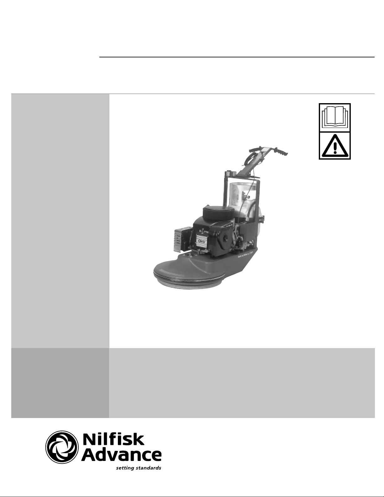
SelectGloss™ 21P
OPERATOR MANUAL AND PARTS LISTOPERATOR MANUAL AND PARTS LIST
OPERATOR MANUAL AND PARTS LIST
OPERATOR MANUAL AND PARTS LISTOPERATOR MANUAL AND PARTS LIST
Kent MODEL 56010814
12/99 Form Number 56041488
Page 2

RECORD THIS IMPORTANT INFORMATION
DATE OF PURCHASE
PURCHASED FROM
ADDRESS
CITY STATE ZIP
PHONE CONTACT
MACHINE SERIAL NUMBER
ENGINE
ENGINE SERIAL NUMBER
IMPORTANT PHONE NUMBERS
Medical Emergency
Police
Fire Department
Page 3

WARNING
Safe Operating Practicess
for
Kent by Nilfisk-Advance Propane Powered
Burnishers
Give serious consideration to items marked by this symbol, failure to do so may
cause injury to yourself or others and/or cause damage to the machine.
• Only allow qualified and trained personnel to operate equipment.
• Closely follow maintenance and operating instructions.
• Keep accurate records of maintenance and service in provided log book.
• Remember, routine maintenance NOW will prevent a breakdown LATER.
• Always check oil level before starting.
• Keep nuts and bolts tightened and hose connections snug.
• Refer to engine manufacturer's service manual or contact Nilfisk-Advance for engine repairs or
adjustments not listed in this manual.
• Never alter or reconstruct the fuel system. To do so may be dangerous and will void the factory
warranty.
• Always use U.L., C.T.C./D.O.T. listed cylinders supplied by Nilfisk-Advance.
• Be careful not to cross thread the Rego gas line coupling at the fuel cylinder.
• Always store cylinder outside away from heat and direct sunlight.
• Never leave the machine running unattended.
• Always operate in a well ventilated area. Failure to do so may cause nausea or carbon monoxide
poisoning.)
• Warning: Keep hands and feet clear of rotating pad! Inspect pad holders regularly. (A fractured pad
holder may result in pad fragments causing injury.)
WARNING
WARNING
Have the machine serviced by a certified technician, including an emission check
every three (3) months.
Failure to follow the instructions and warnings appearing in this operating manual or
on machine labels may result in serious injury to the person using the machine and
possibly to other persons and property.
NOTE: This machine is manufactured for commercial use only.
Page 4

SAFE OPERATING PRACTICES (Continued)
Propane Powered Floor Burnishers are designed and manufactured for high speed commercial floor buffing only.
These machines are designed to buff most modern types of floors including composition tile, stone, marble,
terrazzo, and resilient floor covering using floor coatings designed for high speed buffing.
Even though NFPA 58 8-4.5 says... " these machines shall be permitted to be used in buildings frequented by
the public, including the times when such buildings are occupied by the public." Nilfisk-Advance suggests
use when occupancy of a given work area is at a minimum.
These machines should not:
• Be used in nursing homes, hospitals, day care centers etc.
• Be used by unqualified or untrained personnel.
• Be used unless properly maintained and adjusted.
• Be left running unattended.
• Be used on areas with obstructions such as thresholds, floor outlet boxes, etc.
• Be used in rooms without proper ventilation.
These Propane Powered Burnishers are designed with the burnishing head offset to the right side to make it
easier to burnish the floor close to the edge. It is recommended to start burnishing on the right side of the aisle,
turn and come back down the isle in the opposite direction overlapping the previous path slightly. Continue this
pattern until the floor area to be burnished has been covered with the last pass being on the right side of the
machine. The forward speed is generally at a normal walking speed.
Caution: Do not allow the burnisher to operate without moving. It may burn the floor and could cause
damage to the floor covering.
SPECIFICATIONS
SELECTGLOSS™ 21P
Pad Size ..............................................................21" (53.3cm)
Pad Speed .......................................................... 2000 RPM
Width ................................................................... 22.75" (57.8 cm)
Length ................................................................. 51.5" (130.8 cm)
Engine ................................................................. Honda 11 hp
Starting ................................................................110 Volt
Weight ................................................................. 201 lbs. (91.2 kg.)
Deck .................................................................... Cast Alum. Alloy
Vibration .............................................................. Less than 2.5m/s
Sound Level ........................................................ 88 db
2
Page 5

TABLE OF CONTENTS
I. Propane Machine Safety
A. Purpose .................................................................................................................................1
B. Refueling and Storage of Fuel Cylinders ............................................................................... 1
C. Safety in Engineering ............................................................................................................1
D. Use and Care ........................................................................................................................1
II. Machine Preparation
A. Adding Oil ..............................................................................................................................1
B. Filling the Fuel Cylinder .........................................................................................................2
C. Installing the Fuel Cylinder ....................................................................................................2
III. Operating Instructions
A. Starting Instructions ...............................................................................................................2
B. Operation ............................................................................................................................... 3
C. Idling and Stopping the Machine ...........................................................................................3
D. Installing and Changing the Buffer Pad ................................................................................. 3
E. Storage .................................................................................................................................. 3
F. Transportation .......................................................................................................................3
IV. Scheduled Maintenance ..........................................................................................................4
V. General Maintenance Procedures
A. Fuel System
1. Adjusting the Regulator .................................................................................................5
2. Engine Dust Filter ..........................................................................................................5
3. Carburetor Air Filter .......................................................................................................5
4. Fuel Hose and Connections ..........................................................................................5
B. Engine Maintenance
1. Cooling Fins ..................................................................................................................5
2. Head Bolts .....................................................................................................................5
3. Changing Oil..................................................................................................................6
C. Belt Maintenance...................................................................................................................6
D. Adjusting the Handle .............................................................................................................7
VI. Troubleshooting .........................................................................................................................7
VII. Drawing and Parts List
A. Honda Engine, Deck, and Handle Drawing and Parts List ................................................8,9
Page 6

WARNING
I. Propane Machine Safety
A. Purpose
The accepted demand for and use of propane powered burnishers underscores the need
for responsible manufacturers and users to stress the importance of safety. This manual is
designed to provide the information you need to ensure proper and safe use of propane
powered burnishers.
In addition, we recommend operators of propane powered burnishers to complete a
program of training and certification on the safe operation of this equipment.
B. Refueling and Storage of Fuel Cylinders
Propane cylinders should only be filled by an authorized propane dealer. When not in use, they should
always be stored outside in an upright position in a secure, tamper-proof, steel mesh storage cabinet.
This cabinet may be located next to the building but with at least five feet of space between the cabinet
and the nearest building opening (door or window).
The National Fire Protection Association (NFPA) Standard for Storage and Handling of LP Gas is the
appropriate U.S.A. authority on safe propane use. A copy of this publication is available through the
National Fire Protection Association in Quincy, Massachusetts (1-800-334-3555).
C. Safety in Engineering
Nilfisk-Advance engineers and manufactures machines utilizing U.L. (Underwriters Laboratories)
approved components where possible. The U.L. logo will be affixed to a particular component. This
means the component is listed. Component recognition for the following parts is important: fuel
cylinders, couplings, regulators, and fuel lines. We strongly recommend that you use only machines
meeting the above minimum requirements. Even though the Kent propane powered burnishers meet
the O.S.H.A. Time Weighted Average (TWA) standard for noise, we still recommend hearing protection
be worn by the operator.
WARNING
D. Use and Care
Enclosed with your propane burnisher is a detailed Operator's Manual. Safety dictates that before
using any new equipment, read and understand the Operators Manual. We strongly recommend
this practice.
II. Machine Preparation
A. Adding Oil
The Burnisher is shipped by overland freight with the correct amount of oil in the engine. Air freight
shipments require the machine to be shipped without oil.
When Filling a "Dry" Burnisher or Changing The Oil:
Honda Engine: Add no more than 1 quart, then check the dipstick in the fill cap. Add oil if
necessary but DO NOT OVERFILL! Always check oil before using the machine.
NOTE: Honda engines use premium quality SAE 30, single viscosity motor oil.
IMPORTANT: When checking oil, be sure that the machine is level. Fill cap should be fully
screwed out and free. Do not check oil by screwing cap in and then out again. This will give a
false reading.
1
Page 7

II. Machine Preparation (continued)
B. Filling the Propane Fuel Cylinder
Nilfisk-Advance uses the 20 lb. capacity aluminum fuel cylinder which meets the D.O.T. 4E240
standards. These cylinders are also listed by U.L.. Filling should ONLY be done by a qualified propane
dealer. A properly filled cylinder should not exceed 80% of the rated capacity.
DO NOT attempt cylinder repair. Return the cylinder to your propane dealer if repair is necessary.
Please note that D.O.T. regulations prohibit shipping of cylinders after the cylinder has been filled
WARNING
with propane.
C. Installing the Fuel Cylinder
Strap the cylinder in place by clamping the toggle assembly to the cylinder band. Adjust the toggle
assembly by screwing in or out in order to keep the tank firmly secured. Connect the fuel hose coupling
to the service valve by turning right (clockwise). HAND TIGHTEN ONLY. Make sure coupling is not
cross threaded and check for leakage by noting any odors of propane immediately after cylinder is
connected. (It is sometimes easier to install if the connection to the service valve is made before
strapping the cylinder in place.
To remove cylinder, reverse above procedure. Always connect or change cylinders in a well ventilated
area.
III. Operating Instruction
WARNING
A. Starting Instructions
1. Check oil and fuel levels.
2. Check and clean engine air filter.
NEVER RUN CONTINUOUSLY FOR MORE THAN 1 HOUR WITHOUT CLEANING OR
CHANGING ENGINE DUST FILTER. (See Scheduled Maintenance)
3. Check carburetor air filter. Change if necessary. (See Scheduled Maintenance).
4. Turn propane service valve on the fuel cylinder counter-clockwise to open.
5. Allow machine to tilt backward (pad off floor) and move the throttle to the SLOW position.
6. Plug electric cord into 110 volt wall receptacle and onto starter switch.
7. Engage starter by pushing the button on starter switch.
Note: Do not engage starter for more than 10 seconds. Allow a 60 second cool down period for
each 10 second start-up cycle. If the starter overheats an internal overload switch will prevent it
from operating until cooled. Wait 15 or 20 minutes before trying again.
8. After engine starts, adjust the throttle to the proper speed.
B. Operation
1. After engine has started, allow approximately 30 seconds for the engine to "warm up" then
advance the throttle to operating speed.
2. Lower the burnishing head to the floor while moving the machine forward.
CAUTION!! Do not run the machine without moving. If allowed to run in one spot damage to the
floor may occur.
3. To stop burnishing, push down on handle raising the burnishing head off the floor.
2
Page 8

III. Operating Instructions (continued)
C. Idling and Stopping the Machine
If for any reason the machine needs to idle for short periods of time, simply raise the burnishing head and
move the throttle to the SLOW position.
WARNING
WARNING
Allowing the engine to idle excessively will increase the concentration of carbon monoxide!
To stop the engine, close the service valve on the fuel cylinder by turning it clockwise. (The engine will stop
when the fuel in the lines has been depleted).
NOTE: FOR EMERGENCY STOP: Pull throttle lever all the way back, this will activate the "KILL" switch.
D. Installing/Changing Burnishing Pad
1. With engine OFF, turn the machine over on the RIGHT side (the starter side). This can easily be
accomplished by pushing down on the right handle grip with some force while the machine is tilted
back.
2. Carefully pull old pad off the velcro pad holding material.
3. Carefully inspect the padholder for cracks or damage. Replace if necessary.
NOTE: A damaged padholder rotating at high speeds may be an extreme hazard if it should come
apart.
4. Pull center from new pad, center pad on padholder and tuck the center under the plastic center ring.
5. Press pad onto velcro.
6. Return machine to upright position.
E. Storage
WARNING
Only authorized, trained personnel should have access to propane cylinders and machines.
1. Remove propane fuel cylinder when not in use and store it outside in a storage cage in
accordance with NFPA Chapter 5-4.2.1. Do not release or bleed propane inside of building.
Please consult your local Fire Marshall to insure that you are in compliance with local fire codes.
2. Store machine away from objects that may fall and damage it.
3. Never store machine or fuel cylinders near an open flame or heat producing devices.
4. Make sure machine is cleaned properly before storing.
5. Never store machines with cylinders installed, or spare cylinders, in an enclosed van or trailer.
F. Transportation
When transporting a propane powered burnisher with the fuel cylinder installed, the cylinder should be securely
fastened with the service valve closed and the machine should be secured in the vehicle. Any
propane fuel cylinders not installed on a machine should be securely fastened to avoid movement and
damage. The service valves should be closed. Never store machines with cylinders installed, or spare
cylinders, in an enclosed van or trailer.
It is good practice to check propane cylinders for overfilling before transporting them. If overfilled, correct
before loading them in the vehicle by venting the excess propane outside in a safe area using the fixed liquid
level gauge.
3
Page 9

IV. SCHEDULED MAINTENANCE
Following proper scheduled maintenance procedures will provide years of uninterrupted service.
REGULAR SERVICE PERIOD
(Performed At Indicated Hour Intervals)
ITEM or TYPE of SERVICE
Each
Use 20 hrs. 50 hrs. 100 hrs. 300 hrs.
Engine Oil Check Level 2
Change 2,4,5
Engine Dust Filter Inspect 1
Clean/Change 1,2
Carburetor Air Cleaner Inspect 2
Clean/Change 2,4,5
Belt Inspect 2
Adjust/Replace As Required (5 below)
Fuel Hose & Connections Inspect 2
Replace If Signs of Wear are Present (3,5)
Cooling Fins Clean 2
Burnishing Head Assembly Inspect 6
Padholder Inspect When Changing Pads
Replace If Cracks Appear (7)
Bolts & Connections Inspect 6
Tighten 6
Spark Plug Clean/Replace 5,6 4,5
Valve Clearance Check 3,4,5
Exhaust Emissions Check 3,5
2,4,5
2,4,5
WARNING
1. Perform after each hour of operation.
2. Refer to Section V "General Maintenance Procedures".
3. These items should be serviced by an authorized Kent Service Center.
4. Refer to Engine Manufacturer's "Owners Manual" for recommended replacement.
5. Always enter maintenance performed in "Service Log Book"
6. Routine maintenance.
4
Page 10

WARNING
V. General Maintenance Procedures
A. Fuel System
The fuel system works from vacuum created by the engine running. Turning the safety fill cylinder valve on
pressurizes the system for flow to the carburetor once the engine starts to crank.
1. Adjusting the Regulator:
Note: The regulator and carburetor, on this machine has been factory pre-set. Only Kent authorized
personnel trained and certified in propane fuel systems, should modify
or adjust the system or its settings.
N.F.P.A. 58 8-1.4 states, "In the interest of safety, each person engaged in installing,
repairing, filling, or otherwise servicing an LP-Gas engine fuel system shall be properly
trained in the necessary procedures."
2. Engine Dust Filter
The engine dust filter should be cleaned each hour and after each use by rinsing with mild
detergent.
Squeeze out excess water (do not wring). Allow the filter to air dry.
WARNING
WARNING
Failure to maintain a clean engine air filter will cause the engine to overheat. Also, it may
cause the exhaust emissions to elevate to harmful levels!
3. Carburetor Air Filter
a. Loosen wing nut on top of air cleaner cover.
b. Remove foam pre-cleaner and paper filter element.
c. Clean foam pre-cleaner using the same procedure as "2" above.
d. Clean filter seal, making sure no dust is allowed in carburetor inlet.
e. Inspect paper element. Replace the paper element if dirty, bent or damaged.
f. Install the clean paper element, pre-cleaner, air cleaner cover and wing nut.
Note: Failure to maintain a clean air filter may produce excessive carbon monoxide
emissions. Inspect it before each operation!
4. Fuel Hose and Connections
a. Inspection
(1) Inspect hose for abrasions and other signs of wear; replace all worn or damaged
hoses.
(2) Check for gas leaks by spreading a soapy water solution around all connections with
the service valve OPEN and the fuel system pressurized.
b. Fixing Leaking Joints
(1) Uncouple bad joint, clean joint then apply pipe sealing compound (Loc-Tite Pipe
Sealant with Teflon or equivalent) to clean joint.
(2) Recouple joint finger tight plus 1/2 turn.
(3) Recheck for leaks using soap and water solution and watching for bubbles at
the joint with fuel cylinder service valve turned OPEN and the fuel system
pressurized.
B. Engine Maintenance
1. Cooling Fin Maintenance
a. Remove the blower housing and other cooling shrouds.
b. Clean the cooling fins as necessary.
c. Reinstall the blower housing and other cooling shrouds.
2. Head Bolt Maintenance
Refer to Engine Manufacturer's Service Manual.
5
Page 11

WARNING
B. Engine Maintenance (continued)
3. Changing the Oil
a. Run engine for 5 minutes to warm oil.
b. Locate oil drain plug and place a receptacle where the oil will drain into the receptacle.
c. Open the oil drain plug.
d. Allow oil to drain completely into receptacle.
e. Close the oil drain plug and set the machine upright.
f. Tighten the drain plug and wipe any remaining oil from the engine and deck.
g. Remove the oil fill cap/dipstick. For Honda engines slowly add 1quart of 10W-40 SE or
SF oil.
h. Check oil level with dipstick. Add additional oil if necessary.
DO NOT OVERFILL AND NEVER RUN ENGINE LOW ON OIL!
Important: Honda Engines: When checking oil, be sure that the machine is level. Fill cap
should be fully screwed out and free. Do not check oil by screwing cap in and then out
again. This will give a false reading.
i. Replace filler cap/dipstick and hand tighten.
Note: Care should be taken when changing the oil. Used motor oil should be treated as a
hazardous material.
C. Belt Maintenance
To inspect the belt it is necessary to turn the machine over on the right side (Starter side) for Honda models,
This can be easily accomplished by pushing down on the right handle handle grip with some force while the
machine is tilted back. If the belt is badly cracked or worn it should be replaced.
To check for the proper tightness squeeze the belt together. The belt should depress between 1/4" and 1/2".
To Change belt:
1. Turn the machine over on the right side.
2. Remove the padholder by holding the end of the shaft on the top of the machine with a 3/4"
wrench and turn the padholder counter-clockwise.
3. Using the 3/4" wrench to turn the end of the spindle shaft on top of the machine while removing
the old belt from the spindle pulley.
4. Finish removing the belt from the engine pulley, if necessary.
5. Check engine pulley for correct alignment with the spindle pulley. Check hardware attaching
pulleys for correct tightness.
6. Install the new belt onto the engine pulley.
7. Reinstall the new belt onto the spindle pulley using the 3/4" wrench to turn the spindle clockwise.
Make sure the belt is correctly placed on the idler pulley.
8. Reinstall the padholder onto the spindle shaft.
9. Turn the machine upright in the burnishing position.
10. Check belt for correct operation. Check all hardware for correct tightness.
6
Page 12

D. Adjusting the Handle
* Insert lever bolt through handle bracket and hinge bushing to locate handle in operating
position.
VI. TROUBLESHOOTING
SYMPTOM POSSIBLE CAUSES
1. Hard to Start Spark plug or head bolts loose. Blown head
2. Will Not Start No fuel, Blown head gasket, Insufficient vacuum
3. Engine lacks power Leaking head gasket. Insufficient vacuum.
4. Smell of burned rubber Belt out of adjustment or not aligned properly.
5. Machine vibrates Loose bolts. Pad not centered.
6. Machine "Bogs Down" When in Use Operator is bearing down too hard. Dirty air
gasket. Insufficient vacuum. Coil, air gap needs
adjusting. Low oil.
Defective Spark Plug, Defective coil, Dirty air
filter, Low oil.
Governor needs adjusting. No compression worn rings. Check air filters.
filters.
7. Machine Pulls To One Side Check for bent wheel bracket.
8. Engine stops running Dirty air filter, High exhaust emissions, Out of
fuel, Low oil.
7
Page 13

Honda
SelectGloss™ 21P
Deck, Engine, & Handle Diagram
8
Page 14

SelectGloss™ 21P
Handle, Deck & Engine Parts List
ITEM REF. NO. DESCRIPTION QTY
101 56630108 Cable, Throttle, Control, 32" ............................1
102 56630102 Block, Wheel, 14GA ........................................1
103 56630148 Bolt, Carriage, 3/8 - 16 x 4, Zinc......................2
104 56630105 Grip, Handle ....................................................2
105 56630133 Rivet, Pop, 1/8 x 1/4 ........................................7
106 56630145 Washer, Flat, 5/16 ...........................................8
107 56630104 Handle, Adjustable Lever ................................1
108 56630149 Nut, Acorn, 3/8 - 16 UNC.................................1
109 56630139 Washer, Flat, 3/8 .............................................2
110 56622099 Velcro, Felt, Black, 1 Yd. .................................2
111 56630107 Toggle, Tank Strap ..........................................1
112 56622129 Bolt, Carriage 3/8 - 16 x 1 1/4..........................5
113 56622120 Nut, Lock, 3/8 NC ............................................5
114 56630087 Regulator, Dry Gas..........................................1
115 56622094 Elbow, Brass, Large, Reg to Fuel....................1
116 56630144 Hose, Clamp, No. 38 .......................................2
117 56630132 Fuel, Line, 3/8", 1 Ft. .......................................2
118 56630131 Hose, Vacuum, 5/32, 1 Ft................................2
119 56630083 Ballcheck, 1/8 NPT ..........................................2
120 56630089 Fitting, 3325 x 4, Reg to Fuelock .....................1
121 56630090 Fitting, 49 x 6, Reg to Fuelock .........................2
122 56630093 Coupler, Quick Rego, Female .........................1
123 56630092 Hose, 12", Regulator .......................................1
124 56630082 Cylinder, Safety Fill, Unpainted, w/Dec. ..........1
125 56630084 Cord, Starter, Electric ......................................1
126 56630114 Pulley, 3.5", Motor Drive .................................. 1
127 56622116 Screw, Set, Hex Socket, 5/16 - 18 x 3/8..........2
128 56622131 Washer, Lock, 1/4............................................2
129 56648248 Fuelock, w/Primer............................................ 1
130 56622115 Tee, 3/16 x 3/16 x 3/16,Nylon..........................1
131 56630095 Guard, Reg./Fuelock, Kent ..............................1
132 56630163 Pad, 21", Blue (pkg of 5) ................................ 1
133 56630146 Screw, BH, 1/4 - 20 x 1....................................6
134 56630138 Washer, Flat, 1/4 ............................................14
135 56630116 Belt, BX-36 ......................................................1
136 56630176 Flexi Disc .........................................................1
ITEM REF. NO. DESCRIPTION QTY
137 56630141 Washer, .755 x 1.005 x .060, SS.....................1
138 56630119 Velcro, Studs ..................................................50
139 56630130 Moulding, 1 1/8, Black, Bumper.....................5 ft.
140 56630137 Nut, Lock, 1/4 .................................................10
141 56622110 Wire, Ground, Hour Meter Assembly...............1
142 56630098 Tensioner, Belt, w/4" Pulley.............................1
143 56630110 Spindle, w/5.54" Pulley, Asm...........................1
144 56622119 Nut, 5/16 - 18 NC.............................................1
145 56622132 Washer, Lock, 5/16..........................................5
146 56630136 Nut, Lock, 5/16 - 18 NC ...................................5
147 56630122 Wheel, w/Bracket 5" ........................................2
148 56630080 Caster, 2 1/2", Rear, 3/4" Stem .......................1
149 56630142 Screw, 6mm x 20mm....................................... 2
150 56622118 Bolt, Flange, M8 x 1.25 x 30............................2
151 56630135 Nut, Flange, M8 - 1.25.....................................2
152 56630134 Screw, BH, 5/16 - 18 x 1 3/4............................1
153 56622109 Wire, Lead, Hour Time Indicator......................1
154 56648249 Nut, Hex, 1/2 - 13, Jam....................................1
155 56622135 Bolt, Hex, 1/2 x 1, NC ......................................4
156 56622122 Bolt, Carriage, 5/16 x 1....................................1
157 56630126 Meter, Hour, Round .........................................1
158 56630143 Screw, Cap, 3/8 x 1 1/4 ...................................1
159 56630078 Deck, 21P Painted Complete .......................... 1
160 56622136 Washer, Flat, 7/16 ...........................................5
161 56622125 Screw BH, 5/16 - 18 x 1...................................9
162 56630140 Screw, Sheet Metal, 8 x 2 1/2..........................2
163 56630150 Screw, Cap, 5/16 - 24 x 1 1/4 ..........................2
164 56622105 Key, 1/4 x 1 1/2" ..............................................1
165 56648240 Padholder, 21", Complete Asm. ......................1
166 56630170 Padholder, 21", w/Studs Only..........................1
167 56622121 Screw, Drill Kwik, 8 x 3/4 .................................2
168 56630085 Starter, 110V, Electric......................................1
169 56630123 Filter, Recoil, Dust, Honda...............................1
170 56622134 Screw, Cap, HH, 1/4 - 20 x 1........................... 2
171 56630067 Element, Air Cleaner ....................................... 1
9
Page 15

Nilfisk-Advance, Inc.
14600 21st Avenue North
Plymouth, MN, 55447-3408
www.nilfisk-advance.com
Phone: 800-989-2235
Fax: 800-989-6566
©1999 Nilfisk-Advance, Inc.,
Plymouth, MN 55447-3408
Printed in the U.S.A.
 Loading...