


Kenmore 27298301491, 27298300491 Owner’s Manual
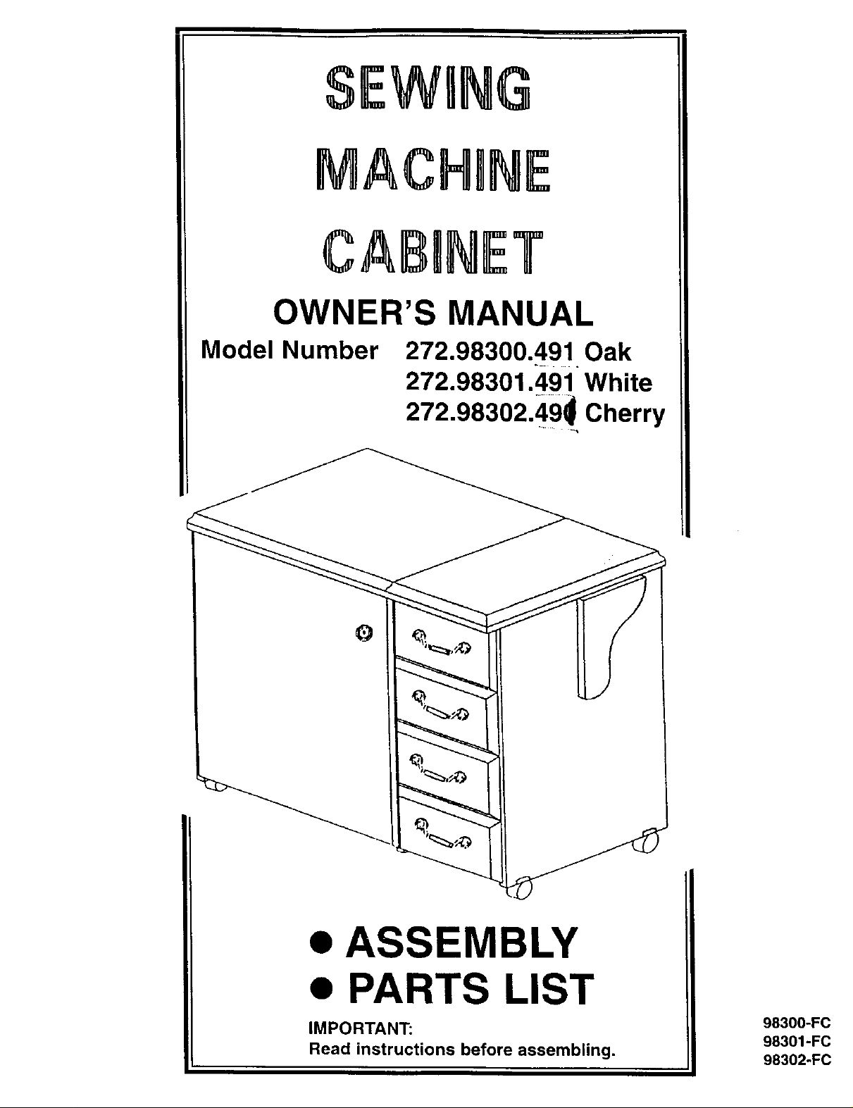
SEWRNG
MACHINE
CABINET
OWNER'S MANUAL
Model Number
272.98300.491 Oak
272.98301.491 White
272.98302.49_ Cherry
ASSEMBLY
PARTS LIST
IMPORTANT:
Read instructions before assembling.
98300-FC
98301-FC
98302-FC
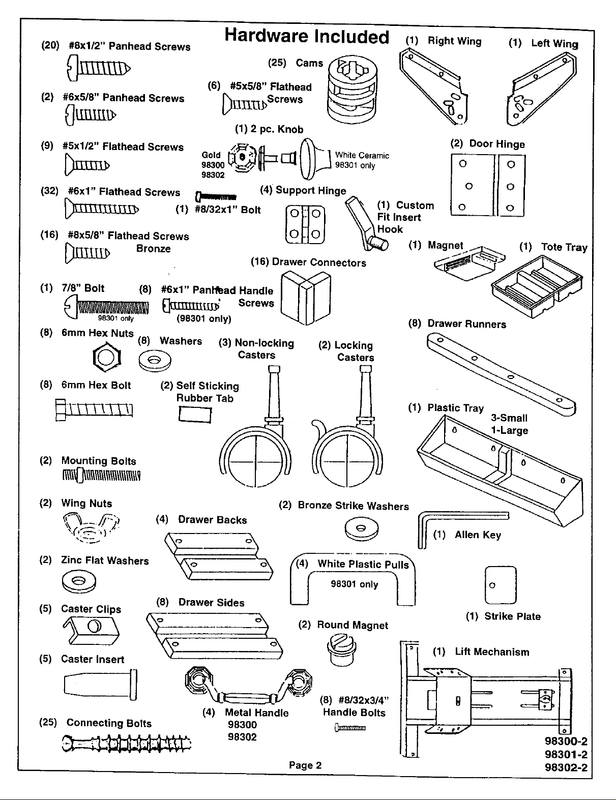
(20) #8xl/2" Panhead Screws
Hardware Included
(1) Right Wing (1) Left Wing
(2) #6x5/8" Panhead Screws
(8) 5ram Hex Bolt
(6) #5x5/8" Flathead _l
(25) Cams_ _ _
_j-_Screws _
(1) 2 pc, Knob
Rubber Tab
(2) Mounting Bolts ('r(/("f I--
(2) Wing Nuts
(2) Zinc Flat Washers
(5) Caster Clips
(5) Caster Insert
(25) Connecting Bolts
(4) Drawer Backs _
(8) Drawer Sides
_o (2) Round Magnet
(4) Metal Handle
98300
98302
(2) Bronze Strike Washers
"_ White Plastic
98301 only
@
(8) #8132x314"
Handle Bolts
Page 2
!
Allen Key
3-Small
1-Large
(1) Strike Plate
hanism
98300-2
98301-2
98302-2
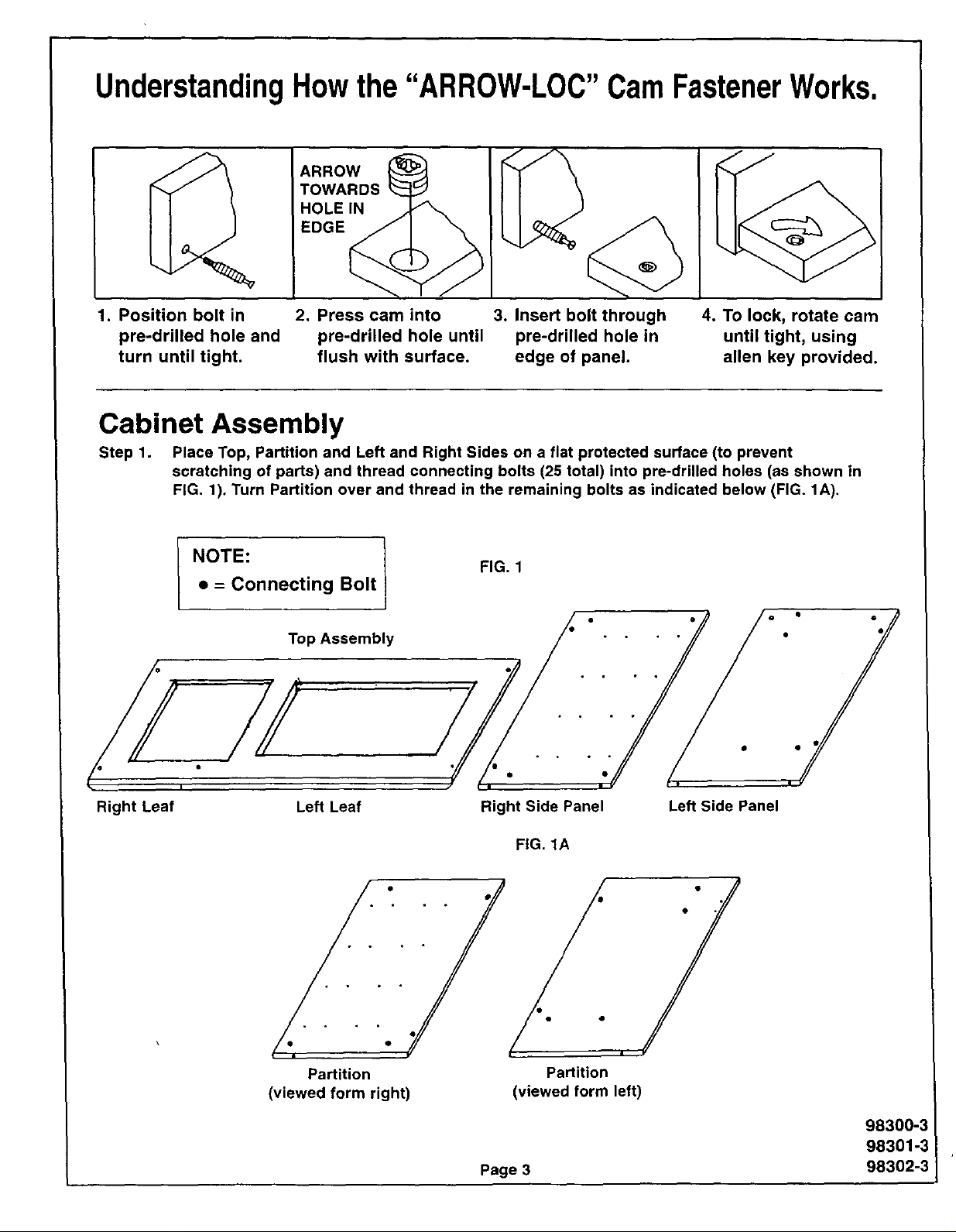
UnderstandingHowthe"ARR0W-LOC"CamFastenerWorks.
ARROW
TOWARDS
HOLEIN
EDGE
1. Position bolt in 2. Press cam into 3. Insert bolt through
pre-drilled hole and pre-drilled hole until pre-drilled hole in
turn until tight, flush with surface, edge of panel.
4. To lock, rotate cam
until tight, using
allen key provided.
Cabinet Assembly
Step 1. Place Top, Partition and Left and Right Sides on a flat protected surface (to prevent
scratching of parts) and thread connecting bolts (25 total) into pre-drilled holes (as shown in
FIG. 1), Turn Partition over and thread in the remaining bolts as indicated below (FIG. 1A).
FIG. 1
• = Connecting Bolt
l NOTE: !
Top Assembly
el
¢
Right Leaf
Left Leaf
• • • • 0 °
Partition Partition
(viewed form right) (viewed form left)
J J
Right Side Panel
FIG. 1A
Page 3
Left Side Panel
98300-3
98301-3
98302-3
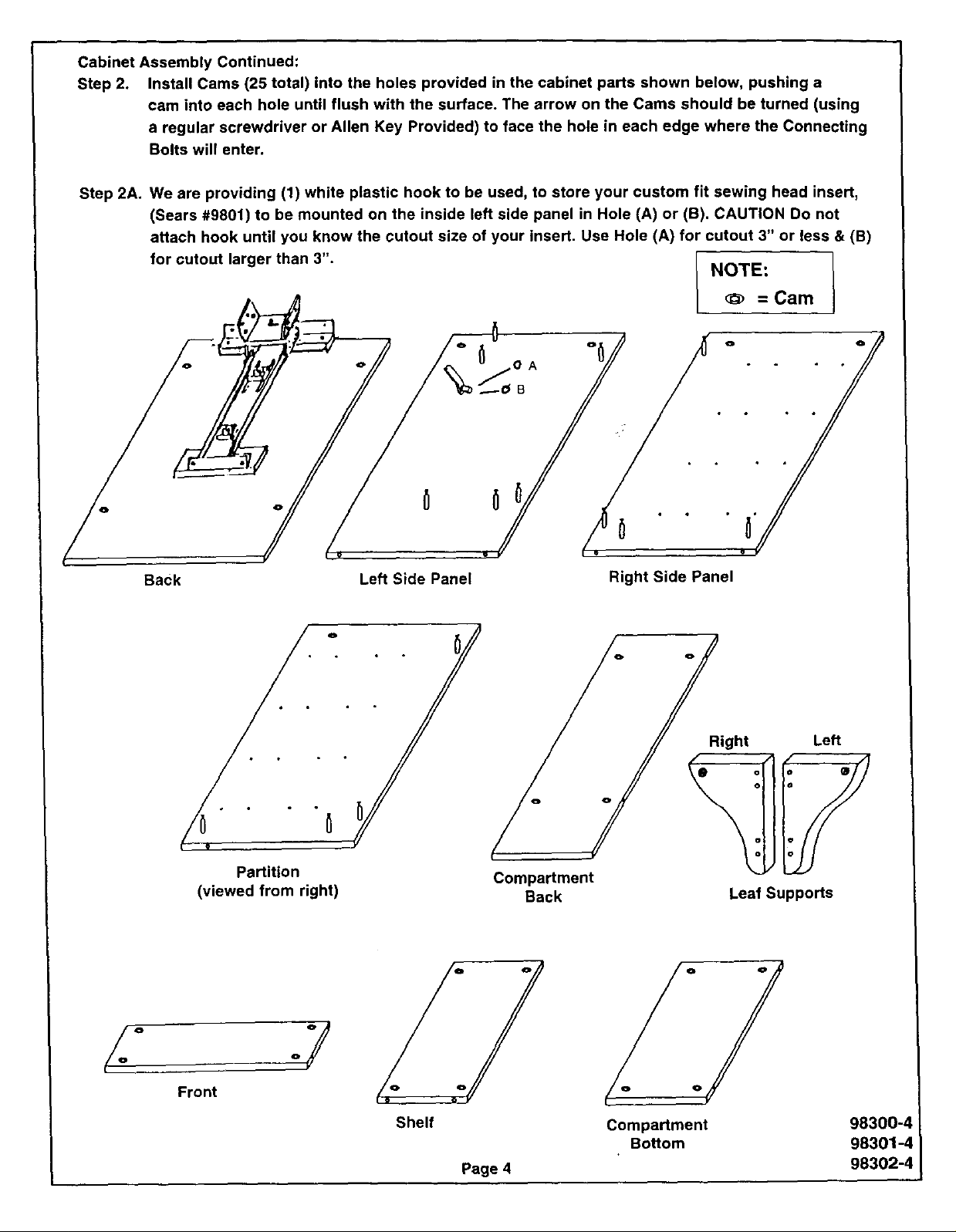
CabinetAssemblyContinued:
Step2• InstallCams(25total)intotheholesprovidedinthecabinetpartsshownbelow,pushinga
camintoeachholeuntilflush withthesurface•Thearrowon theCamsshouldbeturned(using
aregularscrewdriveror Allen KeyProvided)to facetheholeineachedgewheretheConnecting
Boltswill enter•
Step2A•Weareproviding(1)whiteplastichookto beused,tostoreyourcustomfitsewingheadinsert,
(Sears#9801) to be mounted on the inside left side panel in Hole (A) or (B). CAUTION Do not
attach hook until you know the cutout size of your insert. Use Hole (A) for cutout 3" or less & (B)
for cutout larger than 3". NOTE:
= Cam
o /
°• ° • i •
/
Back
• °
Partition
(viewed from right)
Left Side Panel
o
• ° o
0!
Compartment
Back
Right Side Panel
Right Left
Leaf Supports
Front
°y
Shelf
Page 4
Compartment
Bottom
Oi
98300-4
98301-4
98302-4
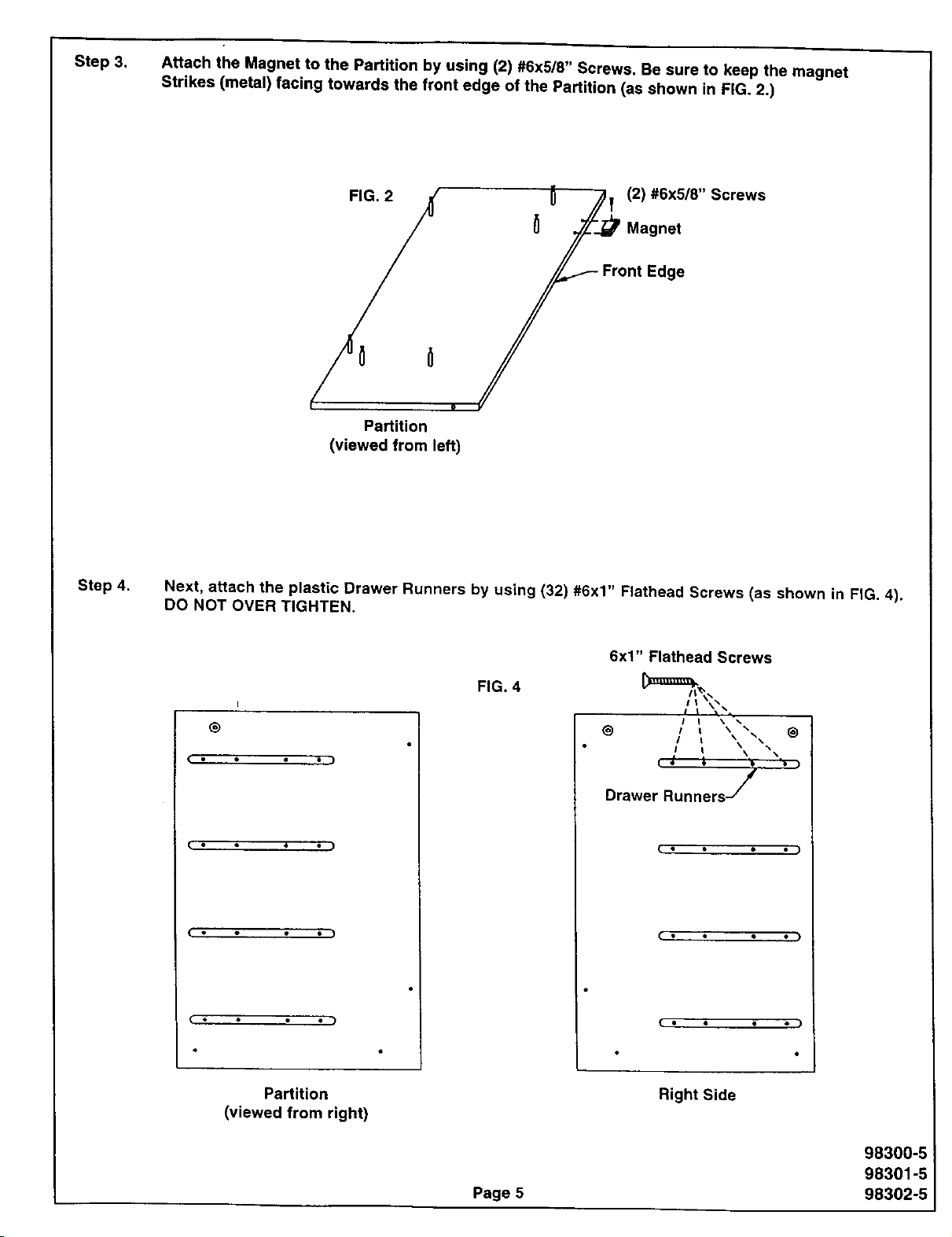
Step 3. Attach the Magnet to the Partition by using (2) #6x5/8" Screws. Be sure to keep the magnet
Strikes (metal) lacing towards the front edge ot the Partition (as shown in FiG. 2.)
(_ /_] (2) #6x5/8" Screws
/uo !
Partition
(viewed from left)
Step 4,
Next, attach the plastic Drawer Runners by using (32) #6x1" Flathead Screws (as shown in FIG. 4).
DO NOT OVER TIGHTEN.
6x1" Flathead Screws
FIG. 4
I
®
• .)
( • • )
C • • )
@ / i
I t
Drawer Runners /
( • • • ,,• )
( • • • .I
Partition
(viewed from right)
Page 5
Right Side
98300-5
98301-5
98302-5
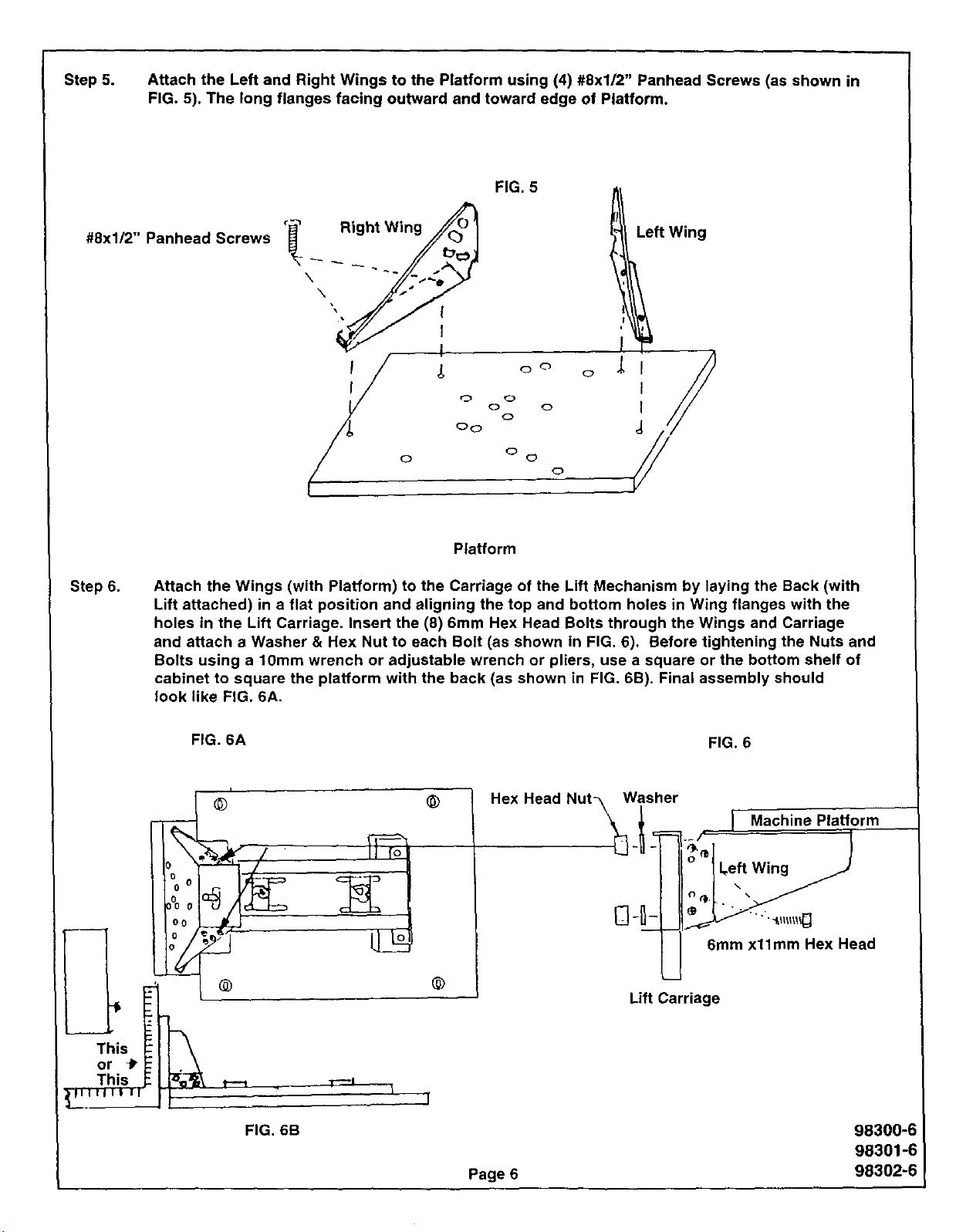
Step 5. Attach the Left and Right Wings to the Platform using (4) #8xl/2" Panhead Screws (as shown in
FIG. 5). The long flanges facing outward and toward edge of Platform.
FIG. 5
#8x1/2" Panhead Screws
Step 6.
o o
0
Platform
Attach the Wings (with Platform) to the Carriage of the Lift Mechanism by laying the Back (with
Lift attached) in a flat position and aligning the top and bottom holes in Wing flanges with the
holes in the Lift Carriage. Insert the (8) 6mm Hex Head Bolts through the Wings and Carriage
and attach a Washer & Hex Nut to each Bolt (as shown in FIG. 6). Before tightening the Nuts and
Bolts using a 10mm wrench or adjustable wrench or pliers, use a square or the bottom shelf of
cabinet to square the platform with the back (as shown in FIG. 6B). Final assembly should
look like FIG. 6A.
FIG. 6A FIG. 6
i
@ @
!
o
I Machine Platform
.ex. a u*\Wis;er:
or _P
This -_
This
® @
_ r-'*l I
FIG. 6B
I'
Page 6
i
L_
Lift Carriage
L,eft Wing
\
6mm x11mm Hex Head
98300-6
98301-6
98302-6
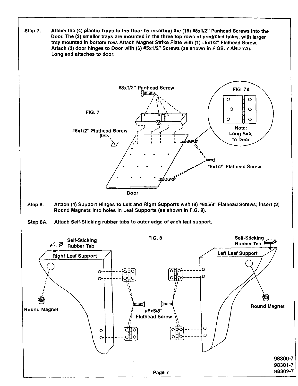
Step 7. Attach the (4) plastic Trays to the Door by inserting the (16) #8xl/2" Panhead Screws into the
Door. The (3) smaller trays are mounted in the three top rows of predrilled holes, with larger
tray mounted in bottom row. Attach Magnet Strike Plate with (1) #5xl/2" Flathead Screw.
Attach (2) door hinges to Door with (6) #5xl/2" Screws (as shown in FIGS. 7 AND 7A).
Long end attaches to door.
#8x1/2" Panhead Screw
#5x1/2" Flathead Screw
Door
Step 8.
Step 8Ao
_// t_ightLeafSupport (//1
Round Magnet \ ] ] ,_ #8x5/8 t
Attach (4) Support Hinges to Left and Right Supports with (8) #8x5/8" Flathead Screws; insert (2)
Round Magnets into holes in Leaf Supports (as shown in FIG. 8).
Attach Self-Sticking rubber tabs to outer edge of each leaf support.
Self-Sticking
d_ Rubber Tab
I I _l FlatheadScrew _,
FIG. 8 Self-Sticking
Rubber Tab
Left Leaf Support
Round Magnet
Page 7
98300°;
98301-7
98302°7
 Loading...