


Kenmore 27298201490, 27298200490 Owner’s Manual
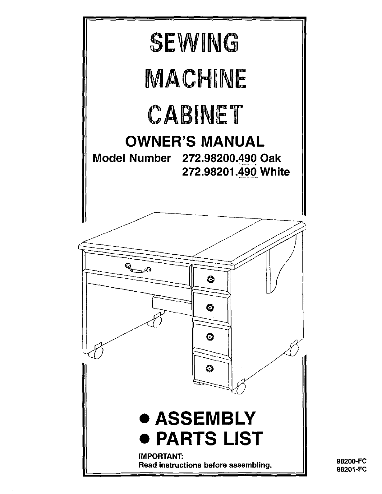
$EWRNG
MACHgNE
CABINET
OWNER'S MANUAL
Model Number 272.98200.490 Oak
272.98201.490 White
ASSEMBLY
PARTS LIST
IMPORTANT:
Read instructions before assembling.
98200-FC
98201-FC
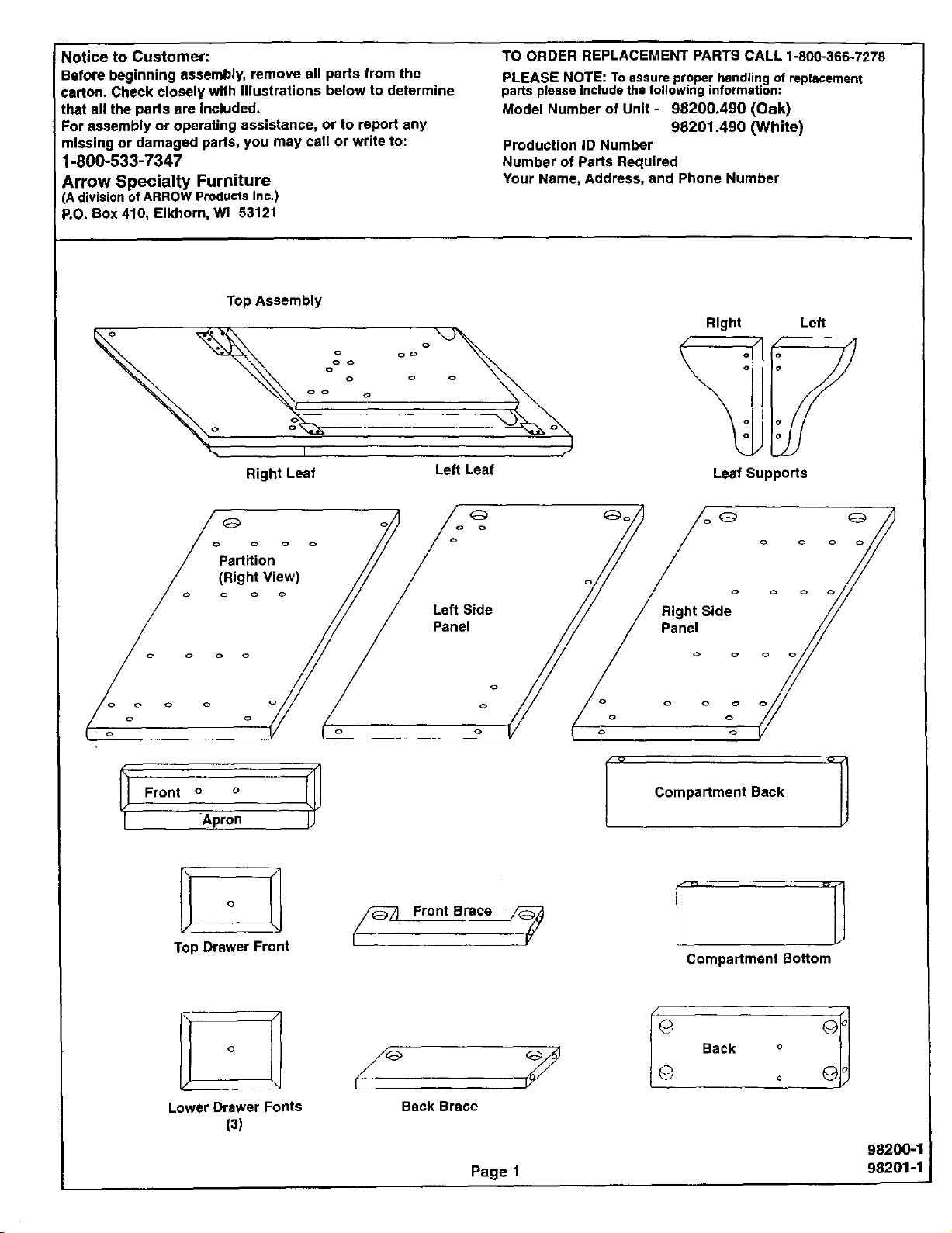
Notice to Customer:
Before beginning assembly, remove all parts from the
carton. Check closely with illustrations below to determine
that all the parts are included.
For assembly or operating assistance, or to report any
missing or damaged pads, you may call or write to:
1-800-533-7347
Arrow Specialty Furniture
(A divisionof ARROW Products Inc.)
RO. Box 410, Elkhorn, Wl 53121
Top Assembly
o o o
o
Right Leaf
Left Leaf
TO ORDER REPLACEMENT PARTS CALL 1-800-366-7278
PLEASE NOTE: To assure proper handling of replacement
parts please include the following information:
Model Number of Unit - 98200.490 (Oak)
98201.490 (White)
Production ID Number
Number of Parts Required
Your Name, Address, and Phone Number
Right Left
o
J
Leaf Supports
Partition
(Right View)
Front o o ]_
I Apron
I°1
Top Drawer Front
__ Front Brace ,/_
Right Side //
Panel° o o o //
o
Compartment Back
]
" °i
Compartment Bottom
I°1
Lower Drawer Fonts
(3)
Back Brace
Page 1
I Q Back o
Q o
98200-1
98201-1
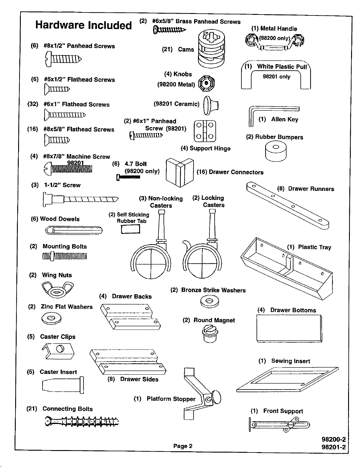
Hardware Included
(2) #6x5/8" Brass Panhead Screws
(1) Metal Handle
(6) #8xl/2" Panhead Screws
(6) #5xl/2" Flathead Screws
(32) #6x1" Flathead Screws
(16) #8x5/8" Flathead Screws
(4) #8x7/8" Machine Screw
,_ 98201 (6) 4.7 Bolt
_..J_\\\\_\_\_\\\\\\\_\\\_\\\\_\_\_\_] 198200 only)
(3) 1-1/2" Screw
(6) Wood Dowels
(2) Self Sticking
Rubber Tab
121) Cams
(4) Knobs
(98200 Metal) _
(98201 Ceramic) (_
(2) #6x1" Panhead
Screw (98201)
(4) Support Hinge
(3) Non-locking (2) Locking
Casters Casters
_1198200 only),_'_
White Plastic
98201 only
(1) Allen Key
(2) Rubber Bumpers
©
Drawer Connectors
(2) Mounting Bolts
(2) Wing Nuts
(2) Bronze Strike Washers
(2) Zinc Flat Washers
(5) Caster Clips
(5) Caster Insert °_ pper_
(21) Connecting Bolts
(4) Drawer Backs
_o <_ (2) Round Magnet
(
(8) Drawer Sides
(1) Platform Sto
I1) Plastic Tray
(4) Drawer Bottoms
@
(1) Sewing Insert
I 1/
(1) Front Support
Page 2
98200-2
98201-2
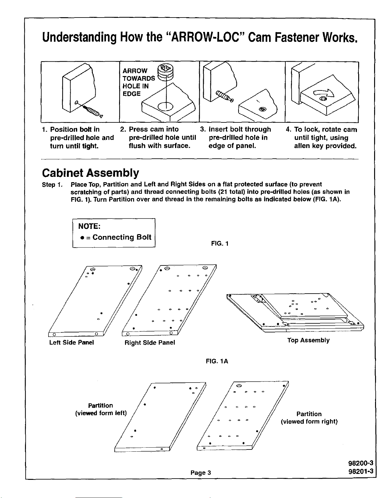
UnderstandingHowthe "ARROW-LOC"CamFastenerWorks.
ARROW
TOWARDS
HOLEIN
EDGE
1. Position bolt in 2. Press cam into 3. Insert bolt through
pre-drilled hole and pre-drilled hole until pre-drilled hole in
turn until tight, flush with surface, edge of panel.
4. To lock, rotate cam
until tight, using
allen key provided.
Cabinet Assembly
Step 1. Place Top, Partition and Left and Right Sides on a flat protected surface (to prevent
scratching of parts) and thread connecting bolts (21 total) into pre-drilled holes (as shown in
FIG. 1). Turn Partition over and thread in the remaining bolts as indicated below (FIG. 1A).
• = Connecting Bolt
NOTE: I
o o o o
o o o o
o o o
o o o
FIG. 1
°°°Zo °°
Left Side Panel Right Side Panel
Partition / °
(viewed form _.
Top Assembly
FIG. 1A
Partition
(viewed form right)
98200-3
Page 3 98201-3
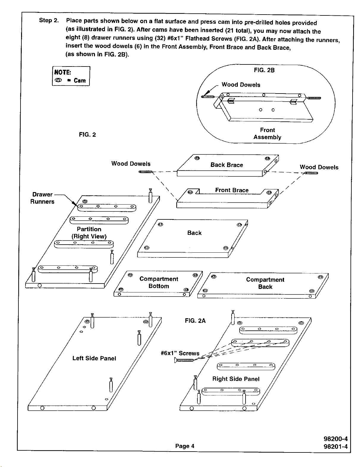
Step 2.
INOTE:
Place parts shown below on a flat surface and press cam into pre-drilled holes provided
(as illustrated In FIG. 2). After cams have been inserted (21 total), you may now attach the
eight (8) drawer runners using (32) #6x1" Flathead Screws (FIG. 2A). After attaching the runners,
insert the wood dowels (6) in the Front Assembly, Front Brace and Back Brace,
(as shown in FIG. 2B).
FIG. 2B
<_ • Cam
FIG. 2
Wood Dowels
Front
Assembly
Wood Dowels / _
Drawer _ F
Runners _o@ o o o
/ Partition
/ (Right View)
Back Brace
x
X
\
Front Brace
S Wood Dowels
/
/
/
W"
Back
Com.mon,.,,j
Le Side Panel // #6x1_/
f o o /
98200-4
Page 4 98201-4
i
 Loading...