


153313530

o S Rs
Electric
i!i_! 7
Water Heater N
Owners
Manual
MODEL NOS.
153.313130 30 Gal.
153.313230 40 Gal.
153.313330 30 Gal.
153.313430 40 Gal.
153.313530 52 Gal.
Z
0
GAMA certification applies to all
residential electric water heaters
with capacities of 20 to 120 Gallons.
Input rating of 12 Kw or less at a
voltage no greater than 250 V.
• Installation • OperatiOnwARN,NG" Repair Parts
READ THE GENERAL SAFETY SECTION BEGINNING ON INSIDE COVER AND
THEN THIS ENTIRE MANUAL BEFORE INSTALLING OR OPERATING THIS
WATER H EATER.
Save this Manual for Future Reference.
LU
L

General Safety ..................................................................................................................................2
Table of Contents ......................................................... 3
Introduction ....................................................................................................4
Specifications ...........................................................................
Preparing for the New Installation ..................................................................
Materials and Basic Tools Needed ....................................................................
Materials Needed .................................................................................................................................................. 5
Basic Tools ............................................................................................................................................................ 5
Removing the Old Water Heater ........................................................................
Locating the New Water Heater .........................................................................7
Facts to Consider About the Location .................................................................................................................... 7
Installing the New Water Heater .............................................8-11
Water Piping ......................................................................................................................................................... 8
Temperature-Pressure Relief Valve ......................................................................................................................... 9
Filling the Water Heater ....................................................................................................................................... 10
Wiring Diagram ................................................................................................................................................... 10
Wiring ............................................................................................................................................................ 10,11
Installation Checklist ........................................................................................................................................... 11
Temperature Regulation .................................................................................................._2
Thermostats ......................................................................................................................................................... 12
Temperature Settings ............................................................................................................................................ 12
Thermostat Adjustment ........................................................................................................................................ 12
For Your Information ........................................................... _3,_
Start Up Conditions ............................................................................................................................................. 13
Thermal Expansion ............................................................................................................................................ 13
Strange Sounds .................................................................................................................................................. 13
Operational Conditions .................................................................................................................................. 13,14
Smelly Water ..................................................................................................................................................... 13
"Air" In Hot Water Faucets ................................................................................................................................ 13
Rumbling Noise ................................................................................................................................................. 13
High Temperature Shut Off System ............................................................................................................... 13,14
Not Enough or No Hot Water ............................................................................................................................ 14
Water Is Too Hot ............................................................................................................................................... 14
Periodic Maintenance ...................................................................................................._-_8
Temperatu re-Pressu re Relief Valve Operation ...................................................................................................... 15
Draining .............................................................................................................................................................. 15
Element Cleaning/Replacement ...................................................................................................................... 16-18
Drain Valve Washer Replacement ....................................................................................................................... 18
Service ................................................................................................................................................................ 18
Leakage Checkpoints ............................................................................................................_9
Repair Parts............................................................................i.......................................................20,2_
Warranty ..................................................................... 24
About Your Warranty ........................................................................................................................................... 24
Sears Installation Policy ....................................................................................................................................... 24
Sears Installation Warranty .................................................................................................................................. 24
Thank You forpurchasing a Sears water heater.
Properly installed and maintained, it should give you
years of trouble free service. If you should decide that you
want the new water heater professionally installed by
Sears call the local Sears Service Center or any Sears
store. They will arrange for prompt, quality installation by
Sears authorized contractors.
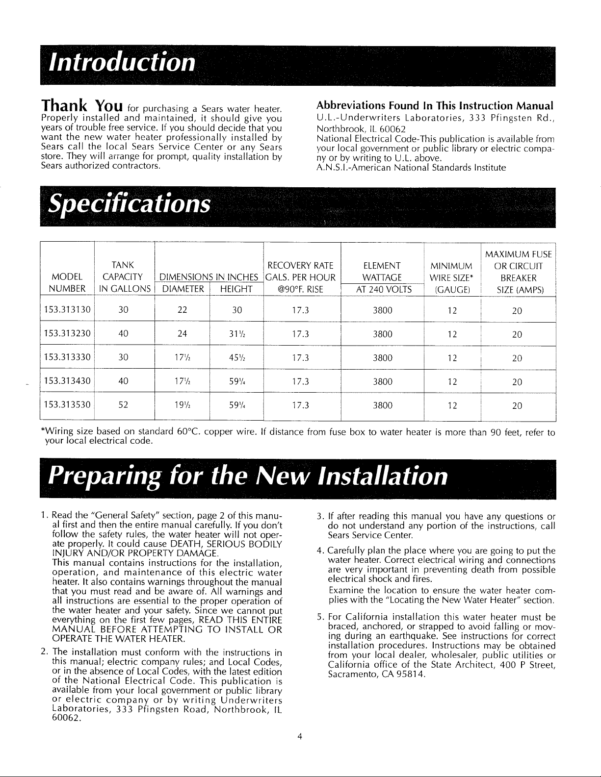
MODEL
NUMBER
TANK
CAPACITY
IN GALLONS
DIMENSIONS IN INCHES
DIAMETER HEIGHT
RECOVERY RATE
GALS. PERHOUR
Abbreviations Found In This Instruction Manual
U.L.-Underwriters Laboratories, 333 Pfingsten Rd.,
Northbrook, IL 60062
National Electrical Code-This publication is available from
your local government or public library or electric compa-
ny or by writing to U.L. above.
A.N.S.I.-American National Standards Institute
@90°F. RISE
ELEMENT
WA-I-FAGE
AT 24O VOLTS
MINIMUM
WIRE SIZE*
(GAUGE)
MAXIMUM FUSE
OR CIRCUIT
[ BREAKER
SIZE (AMPS)
153.313130
153.313230
153.313330
153.313430
153.313530
30
40
40
30
52
22 30
24 31 _/_ 20
171/2 451/2 i 20
17_/_ 59V_ i 20
191/2 59V_ i 20
17.3
17.3
17.3
17.3
17.3
3800
3800
3800
3800
3800
12
12
12
12
12
20
I
i
I
1
*Wiring size based on standard 60°C. copper wire. If distance from fuse box to water heater is more than 90 feet, refer to
your local electrical code.
1.
Read the "General Safety" section, page 2 of this manu- 3.
al first and then the entire manual carefully. If you don't
follow the safety rules, the water heater will not oper-
ate properly. It could cause DEATH, SERIOUS BODILY
INJURY AND/OR PROPERTY DAMAGE. 4.
This manual contains instructions for the installation,
operation, and maintenance of this electric water
heater. It also contains warnings throughout the manual
that you must read and be aware of. All warnings and
all instructions are essential to the proper operation of
the water heater and your safety. Since we cannot put
everything on the first few pages, READ THIS ENTIRE 5.
MANUAL BEFORE ATTEMPTING TO INSTALL OR
OPERATE THE WATER HEATER.
2,
The installation must conform with the instructions in
this manual; electric company rules; and Local Codes,
or in the absence of Local Codes, with the latest edition
of the National Electrical Code. This publication is
If after reading this manual you have any questions or
do not understand any portion of the instructions, call
Sears Service Center.
Carefully plan the place where you are going to put the
water heater. Correct electrical wiring and connections
are very important in preventing death from possible
electrical shock and fires.
Examine the location to ensure the water heater com-
plies with the "Locating the New Water Heater" section.
For California installation this water heater must be
braced, anchored, or strapped to avoid falling or mov-
ing during an earthquake. See instructions for correct
installation procedures. Instructions may be obtained
from your local dealer, wholesaler, public utilities or
California office of the State Architect, 400 P Street,
Sacramento, CA 95814.
available from your local government or public library
or electric company or by writing Underwriters
Laboratories, 333 Pfingsten Road, Northbrook, IL
60062.
4
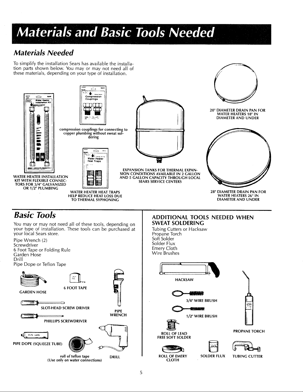
Materials Needed
To simplify the installation Sears has available the installa_
tion parts shown below. You may or may not need all of
these materials, depending on your type of installation.
m
cz_
Compression
Couplings
compression couplings for connecting to
WATER HEATER INSTALLATION
KIT WITH FLEXIBLE CONNEC-
TORS FOR 3/4" GALVANIZED
OR 1/2 '1PLUMBING
copper plumbing without sweat so|-
WATER HEATER HEAT TRAPS
HELP REDUCE HEAT LOSS DUE
TO THERMAL SYPHONING
dering
m
Water Heater
Heat Traps
EXPANSION TANKS FOR THERMAL EXPAN-
SION CONDITIONS AVAILABLE IN 2 GALLON
AND 5 GALLON CAPACITY THROUGH LOCAL
20" DIAMETER DRAIN PAN FOR
WATER HEATERS 18" IN
DIAMETER AND UNDER
SEARS SERVICE CENTERS
28" DIAMETER DRAIN PAN FOR
WATER HEATERS 26" IN
DIAMETER AND UNDER
Basic Tools
You may or may not need all of these tools, depending on
your type of installation. These tools can be purchased at
your local Sears store.
Pipe Wrench (2)
Screwdriver
6 Foot Tape or Folding Rule
Garden Hose
Drill
Pipe Dope or Teflon Tape
GARDEN HOSE
SLOT-HEAD SCREW DRIVER
PHILLIPS SCREWDRIVER
PIPE DOPE (SQUEEZE TUBE) _.//
(Use only on water connections)
6 FOOT TAPE
PIPE
WRENCH
roll of teflon tape DRILL
ADDITIONAL TOOLS NEEDED WHEN
SWEAT SOLDERING
Tubing Cutters or Hacksaw
Propane Torch
Soft Solder
Solder Flux
Emery Cloth
Wire Brushes
HACKSAW
3/4" WIRE BRUSH
1/2" WIRE BRUSH
ROLL OF LEAD
FREE SOFT SOLDER
ROLL OF EMERY
CLOTH
SOLDER FLUX
PROPANE TORCH
TUBING CUTTER
1
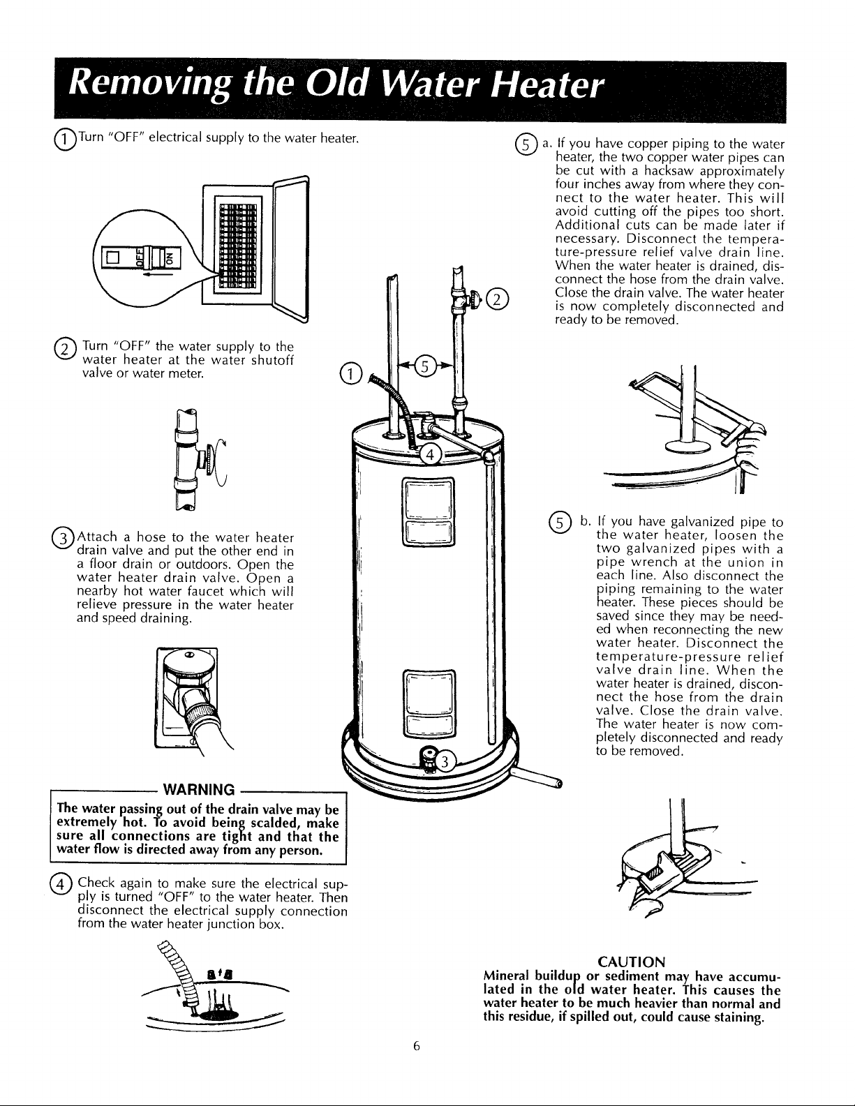
Turn "OFF" electrical supply to the water heater.
I
Q Turn "OFF" the water supply to the
water heater at the water shutoff
valve or water meter.
Attach a hose to the water heater
drain valve and put the other end in
a floor drain or outdoors. Open the
water heater drain valve. Open a
nearby hot water faucet which will
relieve pressure in the water heater
and speed draining.
©
©
a.
©
If you have copper piping to the water
heater, the two copper water pipes can
be cut with a hacksaw approximately
four inches away from where they con-
nect to the water heater. This will
avoid cutting off the pipes too short.
Additional cuts can be made later if
necessary. Disconnect the tempera-
ture-pressure relief valve drain line.
When the water heater is drained, dis-
connect the hose from the drain valve.
Close the drain valve. The water heater
is now completely disconnected and
ready to be removed.
If you have galvanized pipe to
the water heater, loosen the
two galvanized pipes with a
pipe wrench at the union in
each line. Also disconnect the
piping remaining to the water
heater. These pieces should be
saved since they may be need-
ed when reconnecting the new
water heater. Disconnect the
temperature-pressure relief
valve drain line. When the
water heater is drained, discon-
nect the hose from the drain
valve. Close the drain valve.
The water heater is now com-
pletely disconnected and ready
to be removed.
WARNING
The water passing out of the drain valve may be
extremely hot. To avoid being scalded, make
sure all connections are tight and that the
water flow is directed away from any person.
Q Check to make the electrical
disconnect the electrical supply connection
from the water heater junction box.
again
ply is turned "OFF" to the water heater. Then
sure
sup-
CAUTION
Mineral buildup or sediment may have accumu-
lated in the old water heater. This causes the
water heater to be much heavier than normal and
this residue, if spilled out, could cause staining.
Facts to Consider About the
Location
You should carefully choose an indoor location for the
new water heater, because the placement is a very impor-
tant consideration for the safety of the occupants in the
building and for the most economical use of the appli-
ance. This water heater is not intended for outdoor
installation.
Whether replacing an old water heater or putting the
water heater in a new location, the following critical
points must be observed.
1. The location selected should be indoors as close to and
as centralized with the water piping system as possible.
This water heater, as well as all water heaters, will even-
tually leak. Do not install without adequate drainage
provisions where water flow will cause damage.
CAUTION
WATER HEATERS EVENTUALLY LEAK: Installation of the
water heater must be accomplished in such a manner
that if the tank or any connections should leak, the flow
of water will not cause damage to the structure. When
such locations cannot be avoided, a suitable drain pan
should be installed under the water heater. Drain pans
are available at your local Sears Store. Such a drain pan
must be piped to an adequate drain. Under no circum-
stances is the manufacturer or Sears to be held liable for
any water damage in connection with this water heater.
CAUTION
INSTALLATION IN RESIDENTIAL GARAGES: The water
heater must be located and/or protected so it is not
subject to physical damage by a moving vehicle.
2. The location selection must provide adequate clear-
ances for servicing and proper operation of the water
heater.
Water Piping
WARNING
HOTTER WATER CAN SCALD: Water heaters are intend-
ed to produce hot water. Water heated to a temperature
which will satisfy clothes washing, dish washing, and
other sanitizing needs can scald and permanently injure
you upon contact. Some people are more likely to beper-
manently injured by hot water than others. These include
the elderly, children, the infirm, or physically/mentally
handicapped. If anyone using hot water in your home fits
into one of these groups or if there is a local code or
state law requiring a certain temperature water at the hot
water tap, then you must take special precautions. In
addition to using the lowest possible temperature setting
that satisfies your hot water needs, some type of temper-
ing device, such as a mixing valve, should be used at the
hot water taps used by these people or at the water
heater. Mixing valves are available at plumbing supply or
hardware stores. Follow manufacturers instructions for
installation" of the valves. Before changing,,the factory set-
ting on the thermostat, read the Temperature
Regulation" section in this manual.
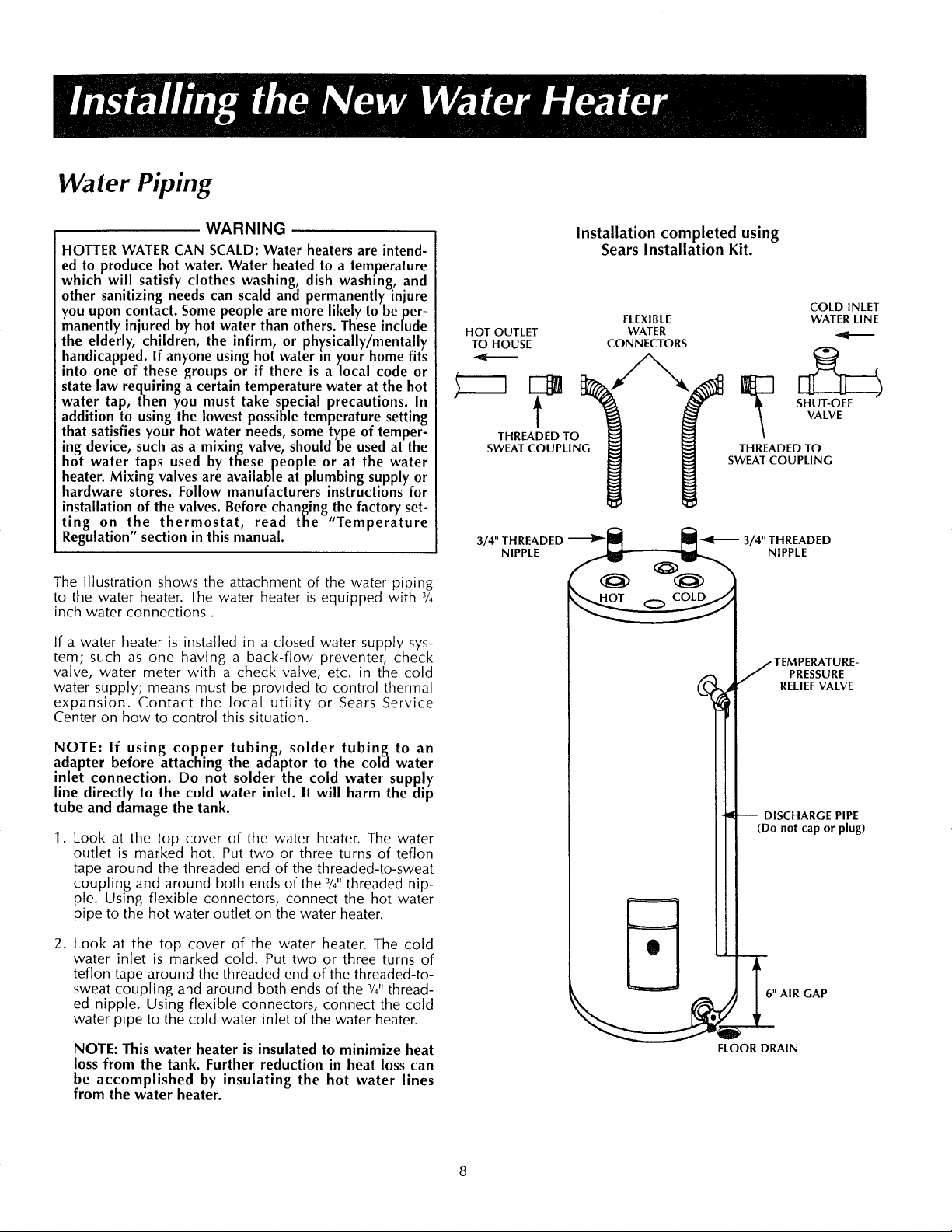
The illustration shows the attachment of the water piping
to the water heater. The water heater is equipped with 3/4
inch water connections.
If a water heater is installed in a closed water supply sys-
tem; such as one having a back-flow preventer, check
valve, water meter with a check valve, etc. in the cold
water supply; means must be provided to control thermal
expansion. Contact the local utility or Sears Service
Center on how to control this situation.
HOT OUTLET
TO HOUSE
t
THREADED TO
SWEAT COUPLING
3/4"THREADED _
NIPPLE
Installation completed using
Sears Installation Kit.
FLEXIBLE
WATER
CONNECTORS
TvLo
THREADED TO
SWEAT COUPLING
_3/4"THREADED
j TEMPERATURE-
• RELIEF VALVE
COLD INLET
WATER LINE
NIPPLE
PRESSURE
NOTE: If using copper tubing, solder tubing to an
adapter before attaching the ad_aptor to the cola water
inlet connection. Do not solder the cold water supply
line directly to the cold water inlet. It will harm the clip
tube and damage the tank.
1. Look at the top cover of the water heater. The water
outlet is marked hot. Put two or three turns of teflon
tape around the threaded end of the threaded-to-sweat
coupling and around both ends of the 3/4"threaded nip-
ple. Using flexible connectors, connect the hot water
pipe to the hot water outlet on the water heater.
2. Look at the top cover of the water heater. The cold
water inlet is marked cold. Put two or three turns of
teflon tape around the threaded end of the threaded-to-
sweat coupling and around both ends of the 3/4"thread-
ed nipple. Using flexible connectors, connect the cold
water pipe to the cold water inlet of the water heater.
NOTE: This water heater is insulated to minimize heat
loss from the tank. Further reduction in heat loss can
be accomplished by insulating the hot water lines
from the water heater.
DISCHARGE PIPE
(Do not cap or plug)
6" AIR GAP
FLOOR DRAIN
 Loading...