

Page 1

Model 2400 Series SourceMeter
Quick Results Guide
®
A GREATER MEASURE OF CONFIDENCE
Page 2

WARRANTY
Keithley Instruments, Inc. warrants this product to be free from defects in material and workmanship for a
period of 1 year from date of shipment.
Keithley Instruments, Inc. warrants the following items for 90 days from the date of shipment: probes, cables,
rechargeable batteries, diskettes, and documentation.
During the warranty period, we will, at our option, either repair or replace any product that proves to be defecti ve.
To exercise this warranty, write or call your local Keithley representative, or contact Keithley headquarters in
Cleveland, Ohio. You will be given prompt assistance and return instructions. Send the product, transportation
prepaid, to the indicated service facility . Repairs will be made and the product returned, transportation prepaid.
Repaired or replaced products are warranted for the balance of the original warranty period, or at least 90 days.
LIMITATION OF WARRANTY
This warranty does not apply to defects resulting from product modification without Keithley’s express written
consent, or misuse of any product or part. This warranty also does not apply to fuses, software, non-rechar geable
batteries, damage from battery leakage, or problems arising from normal wear or failure to follow instructions.
THIS WARRANTY IS IN LIEU OF ALL OTHER WARRANTIES, EXPRESSED OR IMPLIED, INCLUDING ANY IMPLIED WARRANTY OF MERCHANTABILITY OR FITNESS FOR A PARTICULAR USE.
THE REMEDIES PROVIDED HEREIN ARE BUYER’S SOLE AND EXCLUSIVE REMEDIES.
NEITHER KEITHLEY INSTRUMENTS, INC. NOR ANY OF ITS EMPLOYEES SHALL BE LIABLE FOR
ANY DIRECT , INDIRECT, SPECIAL, INCIDENTAL OR CONSEQUENTIAL DAMAGES ARISING OUT OF
THE USE OF ITS INSTRUMENTS AND SOFTWARE EVEN IF KEITHLEY INSTRUMENTS, INC., HAS
BEEN ADVISED IN ADVANCE OF THE POSSIBILITY OF SUCH DAMAGES. SUCH EXCLUDED DAMAGES SHALL INCLUDE, BUT ARE NOT LIMITED TO: COSTS OF REMOVAL AND INSTALLATION,
LOSSES SUSTAINED AS THE RESULT OF INJURY TO ANY PERSON, OR DAMAGE TO PROPERTY.
Keithley Instruments, Inc.
Sales Offices: BELGIUM: Bergensesteenweg 709 • B-1600 Sint-Pieters-Leeuw • 02-363 00 40 • Fax: 02/363 00 64
CHINA: Y uan Chen Xin Building, Room 705 • 12 Yumin Road, Dewai, Madian • Beijing 100029 • 8610-6202-2886 • Fax: 8610-6202-2892
FINLAND: Tietäjäntie 2 • 02130 Espoo • Phone: 09-54 75 08 10 • Fax: 09-25 10 51 00
FRANCE: 3, allée des Garays • 91127 Palaiseau Cédex • 01-64 53 20 20 • Fax: 01-60 11 77 26
GERMANY: Landsberger Strasse 65 • 82110 Germering • 089/84 93 07-40 • Fax: 089/84 93 07-34
GREAT BRITAIN: Unit 2 Commerce Park, Brunel Road • Theale • Berkshire RG7 4AB • 0118 929 7500 • Fax: 0118 929 7519
INDIA: Flat 2B, Willocrissa • 14, Rest House Crescent • Bangalore 560 001 • 91-80-509-1320/21 • Fax: 91-80-509-1322
ITALY: Viale San Gimignano, 38 • 20146 Milano • 02-48 39 16 01 • Fax: 02-48 30 22 74
JAPAN: New Pier T akeshiba North T o wer 13F • 11-1, Kaigan 1-chome • Minato-ku, Tokyo 105-0022 • 81-3-5733-7555 • Fax: 81-3-5733-7556
KOREA: 2FL., URI Building • 2-14 Yangjae-Dong • Seocho-Gu, Seoul 137-888 • 82-2-574-7778 • Fax: 82-2-574-7838
NETHERLANDS: Postbus 559 • 4200 AN Gorinchem • 0183-635333 • Fax: 0183-630821
SWEDEN: c/o Regus Business Centre • Frosundaviks Allé 15, 4tr • 169 70 Solna • 08-509 04 679 • F ax: 08-655 26 10
SWITZERLAND: Kriesbachstrasse 4 • 8600 Dübendorf • 01-821 94 44 • Fax: 01-820 30 81
TAIWAN: 1FL., 85 Po Ai Street • Hsinchu, Taiwan, R.O.C. • 886-3-572-9077 • Fax: 886-3-572-9031
28775 Aurora Road • Cleveland, Ohio 44139 • 440-248-0400 • Fax: 440-248-6168
1-888-KEITHLEY (534-8453) • www.keithley.com
4/02
Page 3

2400 Series SourceMeter
Quick Results Guide
®
©2000, Keithley Instruments, Inc.
All rights reserved.
Cleveland, Ohio, U.S.A.
Third Printing, May 2002
Document Number: 2400S-903-01 Rev. C
Page 4

Manual Print History
The print history shown below lists the printing dates of all Revisions and Addenda created
for this manual. The Revision Le vel letter increases alphabetically as the manual under goes subsequent updates. Addenda, which are released between Revisions, contain important change information that the user should incorporate immediately into the manual. Addenda are numbered
sequentially . When a new Re vision is created, all Addenda associated with the previous Re vision
of the manual are incorporated into the new Re vision of the manual. Each new Re vision includes
a revised copy of this print history page.
Revision A (Document Number 2400S-903-01)........................................................February 2000
Revision B (Document Number 2400S-903-01)..............................................................April 2001
Revision C (Document Number 2400S-903-01)...............................................................May 2002
All Keithley product names are trademarks or registered trademarks of Keithley Instruments, Inc.
Other brand names are trademarks or registered trademarks of their respective holders.
Page 5

S
afety Precautions
The following safety precautions should be observed before using this product and any associated instrumentation. Although
some instruments and accessories would normally be used with non-hazardous voltages, there are situations where hazardous
conditions may be present.
This product is intended for use by qualified personnel who recognize shock hazards and are familiar with the safety precautions
required to avoid possible injury. Read and follow all installation, operation, and maintenance information carefully before using the product. Refer to the manual for complete product specifications.
If the product is used in a manner not specified, the protection provided by the product may be impaired.
The types of product users are:
Responsible body
ment is operated within its specifications and operating limits, and for ensuring that operators are adequately trained.
Operators
instrument. They must be protected from electric shock and contact with hazardous live circuits.
Maintenance personnel
voltage or replacing consumable materials. Maintenance procedures are described in the manual. The procedures explicitly state
if the operator may perform them. Otherwise, they should be performed only by service personnel.
Service personnel
trained service personnel may perform installation and service procedures.
Keithley products are designed for use with electrical signals that are rated Installation Category I and Installation Category II,
as described in the International Electrotechnical Commission (IEC) Standard IEC 60664. Most measurement, control, and data
I/O signals are Installation Category I and must not be directly connected to mains voltage or to voltage sources with high transient over-voltages. Installation Cate gory II connections require protection for high transient over -voltages often associated with
local A C mains connections. Assume all measurement, control, and data I/O connections are for connection to Category I sources unless otherwise marked or described in the Manual.
Exercise extreme caution when a shock hazard is present. Lethal voltage may be present on cable connector jacks or test fixtures.
The American National Standards Institute (ANSI) states that a shock hazard exists when v oltage le vels greater than 30V RMS,
42.4V peak, or 60VDC are present.
circuit before measuring.
Operators of this product must be protected from electric shock at all times. The responsible body must ensure that operators
are prevented access and/or insulated from every connection point. In some cases, connections must be exposed to potential
human contact. Product operators in these circumstances must be trained to protect themselves from the risk of electric shock.
If the circuit is capable of operating at or above 1000 volts,
Do not connect switching cards directly to unlimited power circuits. They are intended to be used with impedance limited sources. NEVER connect switching cards directly to AC mains. When connecting sources to switching cards, install protective devices to limit fault current and voltage to the card.
Before operating an instrument, make sure the line cord is connected to a properly grounded power receptacle. Inspect the connecting cables, test leads, and jumpers for possible wear, cracks, or breaks before each use.
When installing equipment where access to the main power cord is restricted, such as rack mounting, a separate main input power disconnect device must be provided, in close proximity to the equipment and within easy reach of the operator.
For maximum safety, do not touch the product, test cables, or any other instruments while power is applied to the circuit under
test. ALWAYS remo ve power from the entire test system and discharge any capacitors before: connecting or disconnecting ca-
is the individual or group responsible for the use and maintenance of equipment, for ensuring that the equip-
use the product for its intended function. They must be trained in electrical safety procedures and proper use of the
perform routine procedures on the product to keep it operating properly, for example, setting the line
are trained to work on live circuits, and perform safe installations and repairs of products. Only properly
A good safety practice is to expect that hazardous voltage is present in any unknown
no conductive part of the circuit may be exposed.
5/02
Page 6
bles or jumpers, installing or removing switching cards, or making internal changes, such as installing or removing jumpers.
Do not touch any object that could provide a current path to the common side of the circuit under test or power line (earth) ground. Al-
ways make measurements with dry hands while standing on a dry , insulated surface capable of withstanding the voltage being measured.
The instrument and accessories must be used in accordance with its specifications and operating instructions or the safety of the
equipment may be impaired.
Do not exceed the maximum signal levels of the instruments and accessories, as defined in the specifications and operating in-
formation, and as shown on the instrument or test fixture panels, or switching card.
When fuses are used in a product, replace with same type and rating for continued protection against fire hazard.
Chassis connections must only be used as shield connections for measuring circuits, NOT as safety earth ground connections.
If you are using a test fixture, keep the lid closed while power is applied to the device under test. Safe operation requires the use
of a lid interlock.
If or is present, connect it to safety earth ground using the wire recommended in the user documentation.
!
The symbol on an instrument indicates that the user should refer to the operating instructions located in the manual.
The symbol on an instrument shows that it can source or measure 1000 volts or more, including the combined effect of
normal and common mode voltages. Use standard safety precautions to avoid personal contact with these voltages.
The
WARNING
information very carefully before performing the indicated procedure.
The
CAUTION
ranty.
Instrumentation and accessories shall not be connected to humans.
Before performing any maintenance, disconnect the line cord and all test cables.
To maintain protection from electric shock and fire, replacement components in mains circuits, including the power transformer,
test leads, and input jacks, must be purchased from Keithley Instruments. Standard fuses, with applicable national safety approvals, may be used if the rating and type are the same. Other components that are not safety related may be purchased from
other suppliers as long as they are equivalent to the original component. (Note that selected parts should be purchased only
through Keithley Instruments to maintain accuracy and functionality of the product.) If you are unsure about the applicability
of a replacement component, call a Keithley Instruments office for information.
To clean an instrument, use a damp cloth or mild, water based cleaner. Clean the exterior of the instrument only. Do not apply
cleaner directly to the instrument or allow liquids to enter or spill on the instrument. Products that consist of a circuit board with
no case or chassis (e.g., data acquisition board for installation into a computer) should never require cleaning if handled according to instructions. If the board becomes contaminated and operation is affected, the board should be returned to the factory for
proper cleaning/servicing.
heading in a manual explains dangers that might result in personal injury or death. Al ways read the associated
heading in a manual explains hazards that could damage the instrument. Such damage may in v alidate the war -
Page 7

Table of Contents
Introduction ................................................................................... 1
Source-measure capabilities .......................................................... 1
Front and rear panels ..................................................................... 3
Navigating menus and entering numeric data ............................... 4
Menu navigation .................................................................... 4
Numeric data entry (EDIT keys) ............................................ 4
Editing source and compliance values .......................................... 4
Editing keys ........................................................................... 4
Editing procedure ................................................................... 5
Toggling the source and measure display fields ..................... 5
Basic connections .......................................................................... 5
Front/rear terminals selection ................................................ 6
2-wire connections ................................................................. 6
4-wire connections ................................................................. 7
Cable guard ............................................................................ 8
Ohms guard ............................................................................ 8
Remote command programming .......................................... 10
Basic SourceMeter operations .................................................... 10
Source-measure .................................................................... 10
Measure only (V or I) .......................................................... 12
Measure ohms ...................................................................... 13
Remote command programming .......................................... 15
Settings to optimize performance ............................................... 19
Range ................................................................................... 19
Speed .................................................................................... 19
Digits .................................................................................... 20
Filter ..................................................................................... 20
Rel (nulling offsets) ............................................................. 21
Remote command programming .......................................... 22
Features to enhance DUT testing ................................................ 23
Data store ............................................................................. 23
Sweep operation ................................................................... 25
Performing sweeps ............................................................... 29
Limit testing ......................................................................... 34
Math functions ..................................................................... 36
Pulse mode (Model 2430 only) ............................................ 40
Page 8

List of Illustrations
Figure 1 Front panel ................................................................................ 3
Figure 2 Rear panel .................................................................................. 3
Figure 3 2-wire connections .................................................................... 6
Figure 4 4-wire connections .................................................................... 7
Figure 5 Cable guard connections ........................................................... 8
Figure 6 Guarded ohms measurements ................................................... 9
Figure 7 Linear staircase sweep ............................................................. 25
Figure 8 Logarithmic staircase sweep (example) .................................. 26
Figure 9 Custom pulse sweep (example) ............................................... 27
Figure 10 Pulse-measure timing .............................................................. 40
List of Tables
Table 1 SCPI commands; terminals, sense, and cable guard ............... 10
Table 2 Source-measure procedure ...................................................... 11
Table 3 Measure only (V or I) procedure ............................................. 12
Table 4 Auto ohms measurement procedure ........................................ 13
Table 5 Manual ohms measurement procedure .................................... 14
Table 6 SCPI commands; source-measure and measure only............... 16
Table 7 SCPI commands; measure ohms ............................................. 16
Table 8 Command sequence for source-measure example .................. 17
Table 9 Command sequence for measure current only example .......... 17
Table 10 Command sequence for auto ohms example ........................... 18
Table 11 Command sequence for manual ohms example ...................... 18
Table 12 SCPI commands; speed, digits, filter, and rel .......................... 22
Table 13 SCPI commands; data store .................................................... 24
Table 14 Command sequence for data store example ............................ 24
Table 15 SCPI commands; sweeping ..................................................... 31
Table 16 Command sequences for sweep examples .............................. 32
Table 17 SCPI commands; basic non-binning limit testing ................... 35
Table 18 Command sequence for Limit 2 test example ......................... 36
Table 19 SCPI commands; built-in math functions ............................... 39
Table 20 Command sequence for power measurement example ........... 39
Table 21 SCPI commands; select and configure Pulse Mode ................ 44
Table 22 Command sequence for Pulse Mode example ........................ 44
Page 9

Introduction
This guide is designed to familiarize users with fundamental operation (front panel and
remote) of the Keithley 2400 Series SourceMeters. For comprehensive information on all
aspects of SourceMeter operation, refer to the 2400 Series SourceMeter User’s Manual.
Operation information in this guide is divided into four parts; (1) Fundamental sourcemeasure operations, (2) Settings to optimize performance, (3) Features to enhance DUT testing
and (4) More testing techniques. This format allows a new user to easily progress from basic
simple operation to more complex procedures.
2400 Series
SourceMeter
Quick Results Guide
Remote command programming
in this guide, the related SCPI commands for remote operation are summarized in tables. Most
commands have a query form. For e xample, :OUTPut ON turns the output on, while :OUTPut?
requests the present state of the output. Note that the SourceMeter must be addressed to talk
after sending a query command.
For operations where command sequence is important, programming examples are provided. The exact programming syntax will depend on the test program language.
Source-measure capabilities
Model 2400:
• Source voltage from 5µV to 210V; measure voltage from 1µV to 211V.
• Source current from 50pA to 1.05A; measure current from 10pA to 1.055A.
• Measure resistance from 100µ
• Maximum source power is 22W.
- For the various SourceMeter operating modes covered
Ω
(<100µΩ in manual ohms) to 211MΩ.
Page 10

2 Quick Results Guide
Model 2410:
• Source voltage from 5µV to 1100V; measure voltage from 1µV to 1100V.
• Source current from 50pA to 1.05A; measure current from 10pA to 1.055A.
• Measure resistance from 100µ
• Maximum source power is 22W.
Model 2420:
• Source voltage from 5µV to 63V; measure voltage from 1µV to 63.3V.
• Source current from 500pA to 3.15A; measure current from 100pA to 3.165A.
• Measure resistance from 10µ
• Maximum source power is 66W.
Model 2425:
• Source voltage from 5µV to 105V; measure voltage from 1µV to 105.5V.
• Source current from 500pA to 3.15A; measure current from 100pA to 3.165A.
• Measure resistance from 10µ
• Maximum source power is 110W.
Ω
(<100µΩ in manual ohms) to 211MΩ.
Ω
(<10µΩ in manual ohms) to 21.1MΩ.
Ω
(<10µΩ in manual ohms) to 21.1MΩ.
Model 2430:
• Source DC or pulse voltage from 5µV to 105V; measure voltage from 1µV to 105.5V.
• Source DC current from 500pA to 3.15A; measure DC current from 100pA to 3.165A.
• Source pulse current from 500pA to 10.5A; measure pulse current from 100pA to
10.55A.
Ω
• Measure resistance from 10µ
(<10µΩ in manual ohms) to 21.1MΩ.
• Maximum DC source power is 110W.
• Maximum pulse source power is 1.1kW.
Model 2440:
• Source voltage from 5µV to 42V; measure voltage from 1µV to 42V.
• Source current from 500pA to 5.25A; measure current from 100pA to 5.25A.
• Measure resistance from 10µ
Ω (< 10µΩ
in manual ohms) to 21.1 MΩ.
• Maximum source power is 55W.
Page 11
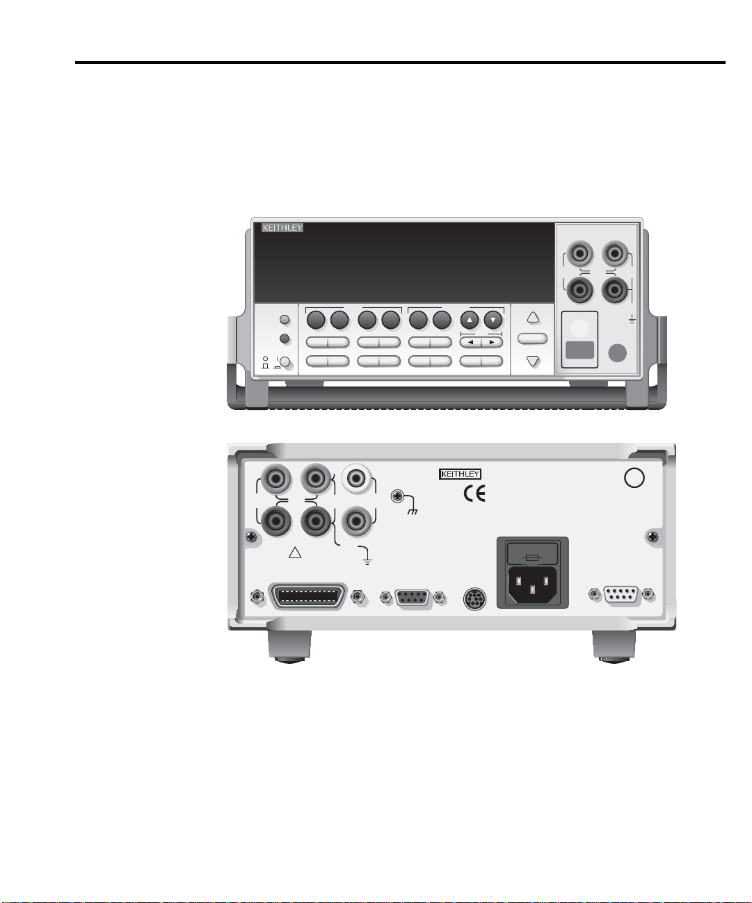
Front and rear panels
WARNING: NO INTERNAL OPERATOR SERVICABLE PARTS, SERVICE BY QUALIFIED PERSONNEL ONLY.
CAUTION: FOR CONTINUED PROTECTION AGAINST FIRE HAZARD, REPLACE FUSE WITH SAME TYPE AND RATING.
The front and rear panels of the Model 2400 SourceMeter are shown in Figures 1 and 2. The
front and rear panels of the other SourceMeter models are similar . The use of the v arious instrument controls and connectors will be explained throughout this guide.
Quick Results Guide 3
Figure 1
Front panel
Figure 2
Rear panel
EDIT
DISPLAY
TOGGLE
POWER
250V
PEAK
4-WIRE
SENSE
WITH FRONT PANEL MENU)
V
LOCAL
67
DIGITS SPEED
HI
5V
PEAK
LO
INPUT/
OUTPUT
!
IEEE-488
(ENTER IEEE ADDRESS
250V
PEAK
4-WIRE
INPUT/
SENSE
OUTPUT
HI
250V
PEAK
2400 SourceMeter
MEAS
250V
PEAK
Ω
230
FILTER
89
RECALL
STORE
GUARD
5V
PEAK
GUARD
SENSE
CAT I
FCTN
LIMIT
V, Ω,
I
1
REL
5V
PK
V
4
TRIG
+/-
CONFIG MENU
RS-232
5
SWEEP
SOURCE
I
EDIT
EXIT ENTER
TRIGGER
LINK
MADE IN
U.S.A.
RANGE
AUTO
RANGE
LINE FUSE
SLOWBLOW
2.5A, 250V
LINE RATING
100-240VAC
50, 60, Hz
190VA MAX.
FUSE DRAWER
ON/OFF
OUTPUT
PEAK
LO
5V
TERMINALS
FRONT/
REAR
OUTPUT
ENABLE
250V
PEAK
250V
PEAK
U
CUS
L
LISTED
SourceMeter
4ZA4
Page 12

4 Quick Results Guide
Navigating menus and entering numeric data
Menu navigation
Many operating modes for the SourceMeter are configured using front panel menus.
Throughout this guide, menu navigation will be presented as a sequence of key presses and
menu item selections. For example, the follo wing sequence selects the auto ohms source mode:
Press CONFIG > press MEAS
The above sequence is explained as follows:
1. Press the CONFIG key.
2. Press the MEAS
3. Select the SOURCE menu item.
4. Select the AUTO ohms source mode.
A menu item is selected by placing the cursor on it and pressing the ENTER key. The
keys control cursor position.
Ω
key.
Ω
> select SOURCE > select AUTO
Numeric data entry (EDIT keys)
Numeric values must to be entered for some menu items. Numeric entry is also used to set
source and compliance values. The edit k eys for numeric entry include the EDIT
to control cursor position, EDIT
the number keys.
After a value is keyed in, press ENTER to select it. Note that pressing MENU resets a displayed number to its minimum value.
and
keys to increment or decrement the digit value, and
Editing source and compliance values
Editing keys
and
and
keys
Use the following keys to edit source and compliance values:
• DISPLAY EDIT — Selects the source or compliance display field for editing. A blinking cursor will appear in the field to be edited. If no key is pressed within a fe w seconds,
the edit mode will be cancelled automatically.
• EDIT
• SOURCE
that pressing either of these keys will automatically enable the source edit mode.
• RANGE
• Numeric keys (0-9) — Allow you to directly enter source or compliance values.
• EXIT — Exits the edit mode without waiting for the time-out period.
and
— Places the display cursor on the display digit to be changed.
or — Increments or decrements the source or compliance value. Note
or — Selects the source or compliance range.
Page 13

Editing procedure
1. Press the DISPLAY EDIT key to place the blinking cursor in either the source or compliance display field to be edited.
2. If desired, use the RANGE
range.
3. To simply increment or decrement the display value, use the EDIT
place the blinking cursor on the digit to be changed, then increment or decrement the
value with the SOURCE
be updated immediately; you need not press ENTER to complete the process.
4. To enter the source or compliance value directly, simply key in the desired value with
the numeric keys while the cursor is blinking. Again, the source or compliance value
will be updated immediately.
and keys to select the desired source or compliance
and keys. Note that the source or compliance value will
Toggling the source and measure display fields
Normally, the measured reading value will appear in the upper, main display line, while the
source and compliance values will appear in the left and right fields respectively of the lower
display line. You can toggle the source and measure display fields by pressing the DISPLAY
TOGGLE key to place the source and measure values in the desired display fields.
Quick Results Guide 5
and
keys to
Basic connections
WARNING
The three basic connection configurations for the SourceMeter include 2-wire local sensing,
4-wire remote sensing, and cable guard.
NOTE
Connections and details for in-circuit ohms measur ements (ohms guard) are co ver ed
in the “Advanced operation” section of this guide.
The SourceMeter uses safety jacks for signal connections. To avoid
electric shock:
• Do not leave exposed connections.
• Properly insulate all external circuits.
• The front and rear terminals of the SourceMeters are rated for connection to circuits rated Installation Category I only. Do not connect the
SourceMeter terminals to CAT II, CAT III, or CAT IV circuits. Connection of the SourceMeter Input/Output terminals, to circuits higher than
CAT I, can cause damage to the equipment or expose the operator to
hazardous voltages.
• Hazardous voltages may be present on the output and guard terminals.
To prevent electrical shock that could cause injury or death, NEVER
make or break connections to the SourceMeter while the unit is on.
Power off the equipment from the front panel or disconnect the main
power cord from the rear of the SourceMeter before handling cables
connected to the outputs. Putting the equipment into standby mode
does not guarantee the outputs are not powered if a hardware or software fault occurs.
Page 14
6 Quick Results Guide
Front/rear terminals selection
The input/output and sense terminals are accessible from both the front and rear panels,
while the guard terminals and chassis ground are only accessible from the rear panel. On the
front panel, press the FRONT/REAR ke y to toggle between front and rear. The REAR annunciator indicates that the rear terminals are selected. With REAR off, the front terminals are
selected.
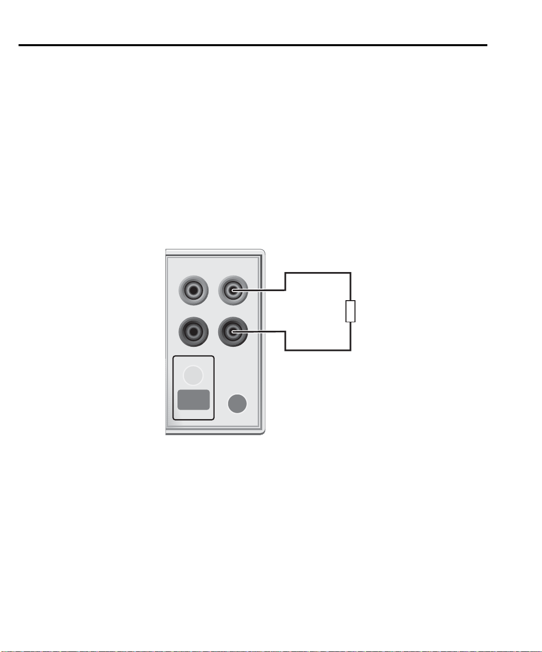
2-wire connections
Connections for 2-wire local sensing are shown in Figure 3. The following menu sequence
selects 2-wire local sensing:
Figure 3
2-wire connections
Press CONFIG > select SOURCE V (or
4-WIRE
SENSE
ON/OFF
OUTPUT
SourceMeter Front Panel
HI
LO
INPUT/
OUTPUT
TERMINALS
FRONT/
FRONT/
REAR
REAR
ΜΕΑS Ω
) > select SENSE MODE > select 2-WIRE
DUT
Sense Selection: 2-wire
Page 15
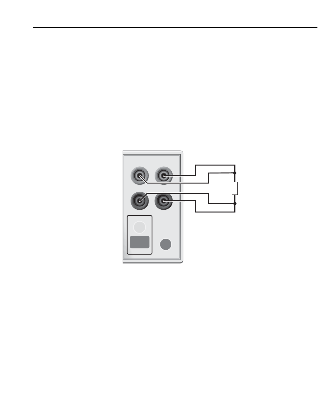
4-wire connections
Connections for 4-wire local sensing are shown in Figure 4. Use 4-wire remote sensing for
the following source-measure conditions:
Quick Results Guide 7
Figure 4
4-wire connections
•Test circuit impedance is <1k
Ω
.
• Optimum ohms, V-source, and/or V-measure accuracy is required.
With 4-wire sensing selected, the 4W annunciator is on. The following menu sequence
selects 4-wire remote sensing:
Ω
Press CONFIG > select SOURCE V (or MEAS
NOTE
Specified accuracies for both source and measure are achieved only using 4-wire
) > select SENSE MODE > select 4-WIRE
remote sensing.
4-WIRE
SENSE
ON/OFF
OUTPUT
HI
LO
INPUT/
OUTPUT
TERMINALS
FRONT/
FRONT/
REAR
REAR
DUT
SourceMeter Front Panel Sense Selection: 4-wire
Page 16
8 Quick Results Guide
WARNING:NO INTERNAL OPERATOR SERVICAB
CAUTION:FOR CONTINUED PROTECTION AGAINST FIR
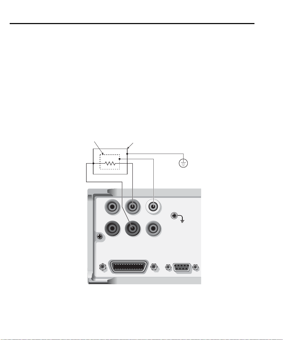
Cable guard
When testing high-impedance DUT (>1GΩ), cable guard is used to drive the shields of
cables and test fixtures to minimize leakage currents and input capacitance. A typical connection scheme using cable guard is shown in Figure 5. The following menu sequence selects
cable guard:
Press CONFIG > press SOURCE V (or SOURCE I or MEAS
CABLE
The guard terminal of the SourceMeter is at virtually the same potential as input/output HI.
Therefore, if there is hazardous voltage at input/output HI, it is also present on the guard shield
for the test circuit.
WARNING
Figure 5
Cable guard connections
Ω
) > select GUARD > select
To prevent injury from electric shock, the guard shield must be enclosed in
a safety shield (i.e., test fixture) that is connected to safety earth ground (as
shown in Figure 5).
Guard Shield
DUT
4-WIRE
SENSE
Test Fixture
HI
LO
INPUT/
OUTPUT
Connect to earth safety ground
using #18 AWG wire or larger.
V, Ω
GUARD
GUARD
SENSE
Ohms guard
Ohms guard allows in-circuit resistance measurements on DUT where other parasitic leakage devices are present. Connection schemes for a Delta DUT configuration is shown in
Figure 6.
IEEE-488
(ENTER IEEE ADDRESS
WITH FRONT PANEL MENU)
RS232
Page 17

Quick Results Guide 9
NOTE
The following menu sequence selects ohms guard:
Press CONFIG > press MEAS
OHMS
Basic connections for ohms guard is shown in Figure 6A. With V,
virtually the same potential, the voltage drop across R will be 0V, and therefore, the current
through R will be 0A. Virtually all the current from In/Out HI will flow through the DUT
resulting in an accurate measurement.
If the guard resistance path (R
enough such that a significant voltage drop appears across R. The resultant leakage current
through R will corrupt the measurement of the DUT.
Guard Sense is used to cancel the effect of IR drop in the V,
Figure 6B. Guard Sense regulates the guard voltage to ensure that the same potential appears
on either side of R.
For DUT <1k
NOTE
Figure 6
Guarded ohms measurements
V, Ω Guard
Ohms guard cannot be used for high current (>100mA) ranges. Ohms guard cannot
be selected if already on a high current range. Conversely, if ohms guard is already
selected, a high current range cannot be selected.
Ω
(or SOURCE V or SOURCE I) > select GUARD > select
Ω
Guard and In/Out HI at
) is <1kΩ, IR drop in the V, Ω Guard test lead could be high
G
Ω
Guard test lead as shown in
Ω
, 4-wire sensing should be used as shown in Figure 6C.
Guard current (IG) must never exceed 50mA. If it does, guard voltage will become
less than the output voltage and corrupt the measurement.
V, Ω Guard
In/Out HI
Sense Mode: 2-wire
In/Out LO
A. Basic connections
0V
DUT
RG
≥1kΩ
V, Ω Guard
Sense Mode: 4-wire
Guard Sense
C. 6-wire connections
R
IG
Sense HI
In/Out HI
In/Out LO
Sense LO
In/Out HI
Sense Mode: 2-wire
In/Out LO
Guard Sense
B. Connections using guard sense
DUT
DUT
RG
<1kΩ
0V
R
IG
Page 18

10 Quick Results Guide
Remote command programming
Table 1 lists the SCPI commands to select terminals, sense, and cable guard.
Table 1
SCPI commands; terminals, sense, and cable guard
Command Description
:ROUTe:TERMinals <name> Selects terminals; <name> = FRONt or REAR.
:SYSTem:RSENse <b> Selects sense mode; <b> = ON (4-wire) or OFF (2-wire).
:SYSTem:GUARd <name> Selects guard mode; <name> = CABLe or OHMS.
Basic SourceMeter operations
Fundamental SourceMeter operations include source-measure, measure only (V or I) and
measure ohms.
Source-measure
There are four source-measure combinations for the SourceMeter:
Source V, Measure I
Source I, Measure V
Source V, Measure V
Source I, Measure I
The basic procedure to source-measure is provided in Table 2. It assumes that the DUT is
already connected to the SourceMeter as explained in
Basic connections
.
Page 19

Quick Results Guide 11
Table 2
Source-measure procedure
Procedure Details
1. Select source function. Press SOURCE V or SOURCE I.
2. Set source level. Use DISPLAY EDIT key to place cursor in source
field (Vsrc or Isrc), use RANGE
and keys to
select range, use edit keys to key in source value,
then press ENTER.
3. Set compliance limit. Use DISPLAY EDIT key to place cursor in Cmpl
field, use RANGE
and keys to select range,
use edit keys to key in limit value, then press
ENTER.
4. Select measurement function. Press MEAS V or MEAS I.
5. If not measuring the source, select
measure range or use auto range (see
Notes 1 and 2).
6. Turn output on and take readings
from display.
Use RANGE and keys to manually select
range. Or press AUTO RANGE (AUTO annunciator on) to enable auto range.
Press ON/OFF OUTPUT key. Red OUTPUT indicator on.
7. Turn output off when finished. Press ON/OFF OUTPUT key. Red OUTPUT indi-
cator off.
Notes:
1. When measuring source (i.e., Source I, Measure I), you cannot change the measure range or enable auto
range. The measure range is determined by the source range.
2. When not measuring the source (i.e., Source I, Measure I), the compliance range determines the maximum
measurement range that can be selected.
Sink operation
When operating as a sink (V and I have opposite polarity), the SourceMeter is dissipating
power rather than sourcing it. An external source can force operation into the sink region. The
SourceMeter can be used to charge/discharge (source/sink) batteries. F or operation information
on battery charging/discharging (and the associated precautions), see Section 3,
of the 2400 Series SourceMeter User’s Manual.
Sink operation
Page 20

12 Quick Results Guide
Measure only (V or I)
The SourceMeter can be used to measure voltage only (voltmeter) or current only (amme-
ter). The procedure to measure only is provided in Table 3.
Table 3
Measure only (V or I) procedure
Procedure Details
1. Select source-measure
functions.
2. Set source level to zero. Use DISPLA Y EDIT key to place cursor in source fi eld (Vsrc
3. Set compliance higher than
the expected measurement
(see CAUTION 1).
4. Select measurement range
(see Note).
5. Connect voltage or current
to be measured.
6. Turn output on and take
reading from display.
7. Turn output off when
finished.
Note: When measuring current, auto range can be used. When measuring voltage, DO NOT use auto range
(see CAUTION 2).
To measure voltage, press SOURCE I and MEAS V. To measure current, press SOURCE V and MEAS I.
or Isrc), use RANGE
key to select lowest range, press
MENU to display zero source level, then press ENTER.
Use DISPLAY EDIT key to place cursor in Cmpl field, use
RANGE
and keys to select range, use edit keys to key
in compliance value, then press ENTER.
Use RANGE and keys to select a fixed measurement
range. For best accuracy, use the lowest possible range.
Connect DUT to SourceMeter using 2-wire connections (see
Figure 3).
Press ON/OFF OUTPUT key. Red OUTPUT indicator on.
Press ON/OFF OUTPUT key. Red OUTPUT indicator off.
CAUTION 1
When using the SourceMeter as a voltmeter only, voltage compliance must
be set higher than the voltage that is being measured. Failure to do so
could result in instrument damage due to excessive current that will flow
into the SourceMeter.
CAUTION 2 When using the SourceMeter as a voltmeter only, DO NOT use auto range
and NEVER select a measurement range that is below the applied signal
level. Otherwise, high current drawn from the external source could damage the external source or the test circuit.
Page 21

Measure ohms
Measurement methods
There are two methods to measure resistance; auto ohms and manual ohms. In auto ohms,
the SourceMeter operates as a conventional constant-current source ohmmeter. You simply
select an ohms measurement range (or auto range) and take the reading from the display.
In manual ohms, the SourceMeter uses the V/I measurement method. After configuring the
source (V or I) and selecting a voltage or current measurement range, the Ω measurement function will display the calculated V/I ohms reading.
Use the following menu sequence to select the auto ohms or manual ohms measurement
method:
Press CONFIG > press MEAS Ω > select SOURCE > select AUTO or MANUAL
Ohms source readback
With source readback enabled, the SourceMeter measures both V and I and uses these v alues
for the ohms calculation. This feature provides optimum accuracy for front panel operation
since the measured source value is more accurate than the programmed source value. For
remote operation, the user specifies the functions to measure.
Use the following menu sequence to enable or disable source readback:
Press CONFIG > press MEAS Ω > select SRC RDBK > select ENABLE or DISABLE
Quick Results Guide 13
Ohms measurement procedures
The auto ohms and manual ohms measurement procedures are provided in Tables 4 and 5.
They assume that the DUT is already connected to the SourceMeter. (See Basic connections.)
Note that resistance accuracy specifications are based on 4-wire sensing.
Table 4
Auto ohms measurement procedure
Procedure Details
1. Select ohms measurement
function.
2. Select auto ohms measurement
method.
3. Select measurement range. Use RANGE and keys to manually select range.
4. Turn output on and take readings
from display.
5. Turn output off when finished. Press ON/OFF OUTPUT key. Red OUTPUT indica-
Press MEAS Ω.
Press CONFIG > press MEAS Ω > select SOURCE
> select AUTO.
Or press AUTO RANGE (AUTO annunciator on) to
enable auto range.
Press ON/OFF OUTPUT key. Red OUTPUT indicator on.
tor off.
Page 22

14 Quick Results Guide
Table 5
Manual ohms measurement procedure
Procedure Details
1. Select ohms measurement
function.
2. Select manual ohms measurement
method.
3. Select source, set source level, and
set compliance limit.
4. Select measurement range (see
Notes 1 and 2).
5. Turn output on and take readings
from display.
6. Turn output off when finished. Press ON/OFF OUTPUT key. Red OUTPUT indica-
Notes
1. If sourcing I, you will be selecting the V measure range. If sourcing V, you will be selecting the I measure
range.
2. The compliance range determines the maximum measurement range that can be selected.
Press MEAS Ω.
Press CONFIG > press MEAS Ω > select SOURCE
> select MANUAL.
See steps 1, 2, and 3 of Table 2.
Use RANGE and keys to manually select range.
Or press AUTO RANGE (AUTO annunciator on) to
enable auto range.
Press ON/OFF OUTPUT key. Red OUTPUT indicator on.
tor off.
Offset-compensated ohms
Thermal EMFs can corrupt low-resistance measurements. An offset-compensated Ω
measurement cancels out unwanted offset by performing the following 2-point measurement
process:
Offset-Compensated Ω = ∆V / ∆I
where: ∆V = V2 - V1
∆I = I2 - I1
V1 and I1 are V and I measurements with the source set to a specific level.
V2 and I2 are V and I measurements with the source set to zero.
1. Select the Ω function, and select the auto or manual ohms measurement method.
2. Enable offset compensation by using the following menu sequence:
Press CONFIG > press MEAS Ω > select OFFSET COMPENSATION > select
ENABLE
3. If using auto ohms, go to the next step. For manual ohms, configure the desired source
(V or I) to output an appropriate source level. Set compliance and select a measurement
range (or use auto range).
4. Turn the output on and observe the offset-compensated ohms reading on the display.
Note that the source value alternates between the set output level and zero.
5. When finished, turn the output off and disable offset compensation.
Page 23

NOTE Manual offset-compensated ohms is also available as a math function (FCTN). This
math function allows you to specify both source levels (see “Math functions” in
“Features to enhance DUT testing.”
In-circuit ohms measurements
Ohms guard allows you make accurate in-circuit ohms measurements on resistor networks.
These measurements are covered in Advanced operation.
Remote command programming
Data string
The :READ? command is typically used to trigger a source-measure action and request the
data string. The data string is sent to the computer when the SourceMeter is addressed to talk.
The data string is typically made up of five elements separated by commas. The first element
is the voltage reading, the second is the current reading, and the third is the resistance reading.
For voltage and current, the reading could be source or measure depending on how the instrument is configured. For example, if sourcing voltage and measuring current, the voltage element is the source reading and the current element is the measured reading. The NAN (not a
number) value of +9.91e37 is used for a function that is not enabled.
Quick Results Guide 15
The fourth data element is the timestamp and the fifth is the status word. See Section 18,
FORMat subsystem, of the 2400 Series SourceMeter User’ s Manual for details on all aspects of
the data format.
NOTE The five element data string is the GPIB default condition.
Page 24

16 Quick Results Guide
SCPI commands
SCPI commands to source-measure and measure only are provided in Table 6, and the com-
mands to measure ohms are provided in Table 7.
Table 6
SCPI commands; source-measure and measure only
Command
2
Description
1
:SOURce:FUNCtion <name> Select source function; <name> = VOLTage or CURRent.
:SOURce:xxx:MODE FIXed Select fixed V or I sourcing mode.
:SOURce:xxx:RANGe <n> Select measurement range for V or I source; <n> = range.
:SOURce:xxx:LEVel <n> Set source amplitude; <n> = amplitude in volts or amps.
[:SENSe]:FUNCtion <name> Select measure function; <name> = “VOLTage” or “CURRent”.
[:SENSe]:xxx:PROTection <n> Set V or I compliance; <n> = compliance.
[:SENSe]:xxx:RANGe <n> Select V or I measure range; <n> = range.
[:SENSe]:xxx:RANGe:AUTO <b> Enable or disable auto range; <b> = ON or OFF.
:OUTPut <b> Turn output on or off; <b> = ON or OFF.
:READ? Trigger and acquire one data string.
1. For measure only, the following rules apply (Table 9 provides an example to measure I only):
a. To measure V only, you must source I. To measure I only, you must source V.
b. The source must be set to 0V or 0A.
c. When measuring V only, DO NOT use auto range.
d. When measuring V only, voltage compliance MUST be set higher than the voltage being measured.
2. :xxx = :VOLTage or :CURRent.
Table 7
SCPI commands; measure ohms
Command Description
[:SENSe]:FUNCtion “RESistance” Select ohms function.
[:SENSe]:RESistance:MODE <name> Select ohms mode; <name> = AUTO or MANual*.
[:SENSe]:RESistance:OCOMpensated <b> Enable/disable offset compensation.
[:SENSe]:RESistance:RANGe <n> Select range for auto ohms; <n> = range.
[:SENSe]:RESistance:RANGe:AUT O <b> Enable or disable auto range for auto ohms; <b> = ON or
OFF.
:OUTPut <b> Turn output on or off; <b> = ON or OFF.
:READ? Trigger and acquire one data string.
*For manual ohms, you must configure the SourceMeter to source-measure. Table 11 provides a programming example to
measure ohms using the manual ohms method.
Page 25

Quick Results Guide 17
Programming examples
Source-measure example — Table 8 shows a typical command sequence to source 10V
and measure current on the 10mA range.
Measure-only example — Table 9 shows a typical command sequence to measure current
only.
Table 8
Command sequence for source-measure example
Command* Comments
*RST Restore GPIB defaults (one-shot source-measure mode).
:SOUR:FUNC VOLT Select voltage source function.
:SOUR:VOLT:MODE FIX Select fixed voltage source mode.
:SOUR:VOLT:RANG 20 Select 20V source range.
:SOUR:VOLT:LEV 10 Set source output level to 10V.
:SENS:FUNC “CURR” Select current measurement function.
:SENS:CURR:PROT 10e-3 Set compliance limit to 10mA.
:SENS:CURR:RANG 10e-3 Select the 10mA measurement range.
:OUTP ON Turn the output on.
:READ? Trigger and acquire one data string.
*SourceMeter must be addressed to talk after sending :READ? to trigger and acquire data.
Table 9
Command sequence for measure current only example
Command* Comments
*RST Restore GPIB defaults (one-shot measure mode).
:SOUR:FUNC VOLT Select voltage source function.
:SOUR:VOLT:MODE FIX Select fixed voltage source mode.
:SOUR:VOLT:RANG 0.2 Select 200mV source range.
:SOUR:VOLT:LEV 0 Set source output level to 0.000mV.
:SENS:FUNC “CURR” Select current measurement function.
:SENS:CURR:PROT 100e-3 Set compliance limit to 100mA.
:SENS:CURR:RANG 10e-3 Select the 10mA measurement range.
:OUTP ON Turn the output on.
:READ? Trigger and acquire one data string.
*SourceMeter must be addressed to talk after sending :READ? to trigger and acquire data.
Page 26

18 Quick Results Guide
Auto ohms example — Table 10 shows a typical command sequence to use auto ohms to
measure resistance. Note that 4-wire sensing is used for this example. See Basic connections
for details on sensing.
Manual ohms example — T able 11 sho ws a typical command sequence to use manual ohms
to measure resistance. This example uses auto range for current measurements. If you were to
use manual ranging, you should select the lowest possible current range for the measurement.
For example, to measure a 1MΩ resistor with the source set to 2V, the 1µA measure range should
be selected to achieve the best accurac y (2V/1µA = 2MΩ). Note that 2-wire sensing is used for
this example. See Basic connections for details on sensing.
Table 10
Command sequence for auto ohms example
Command* Comments
*RST Restore GPIB defaults (one-shot measurement mode).
:SENS:FUNC “RES” Select ohms measurement function.
:SENS:RES:RANG 200 Select 200Ω range.
:SENS:RES:MODE AUTO Select the auto ohms measurement method.
:SYST:RSEN ON Select 4-wire sense mode.
:OUTP ON Turn the output on.
:READ? Trigger and acquire one data string.
*SourceMeter must be addressed to talk after sending :READ? to trigger and acquire data.
Table 11
Command sequence for manual ohms example
Command* Comments
*RST Restore GPIB defaults (one-shot measurement mode).
:SENS:FUNC “RES” Select ohms measurement function.
:SENS:RES:MODE MAN Select the manual ohms measurement method.
:SOUR:FUNC VOLT Select voltage source function.
:SOUR:VOLT:MODE FIX Select fixed voltage sourcing mode.
:SOUR:VOLT:RANG 2 Select 2V source range.
:SOUR:VOLT:LEV 2 Set source level to 2V.
:SENS:CURR:PROT 10e-3 Set current compliance to 10mA.
:SENS:CURR:RANG:AUTO ONSelect auto range for current measurements.
:SYST:RSEN OFF Select 2-wire sense mode.
:OUTP ON Turn the output on.
:READ? Trigger and acquire one data string.
*SourceMeter must be addressed to talk after sending :READ? to trigger and acquire data.
Page 27

Settings to optimize performance
Range
To achieve best accuracy, the SourceMeter should be on the lowest possible measurement
range. In most situations, auto range can be used to automatically select the best range. Auto
range is controlled (enabled/disabled) by the AUTO range key (AUTO annunciator indicates
auto range is enabled).
Quick Results Guide 19
Speed
RANGE
these keys disables auto range.
NOTE Basic ranging information (including the SCPI commands for remote operation) is
Measurement speed is set by setting the integration time of the A/D converter (period of
time the input signal is measured). Integration time affects the usable digits, reading noise, and
the ultimate reading rate of the instrument. It is specified in parameters based on the number of
power line cycles (NPLC), where 1 PLC for 60Hz is 16.67msec (1/60), and 1 PLC for 50Hz
and 400Hz is 20msec (1/50).
In general, the fastest speed setting (FAST; 0.01 PLC) results in increased noise and fewer
usable display digits. The slowest speed (HI A CCURACY; 10 PLC) provides the best commonmode and normal-mode noise rejection. In between settings are a compromise between speed
and noise.
Press SPEED and select one of the following speed setting options:
FAST Sets speed to 0.01 PLC and display resolution to 3½-digits.
MED Sets speed to 0.10 PLC and display resolution to 4½-digits.
NORMAL Sets speed to 1.00 PLC and display resolution to 5½-digits.
HI ACCURACY Sets speed to 1.00 PLC and display resolution to 5½-digits.
OTHER Use to set speed to any PLC value from 0.01 to 10. Display resolution is
and keys are used for manual range selection. Note that pressing either of
covered in “Fundamental source-measure operations.”
not changed after speed is set with this option.
NOTE After setting speed, display resolution can be changed using the DIGITS key.
Page 28

20 Quick Results Guide
Digits
The SourceMeter can display readings at 3½-digit, 4½-digit, 5½-digit or 6½-digit resolution. In situations where the last digits of the reading are noisy, you can turn those digits off by
decreasing display resolution.
To set display resolution, press the DIGITS key until the desired number of digits are displayed. Another way to set display resolution is with the following menu sequence:
Press CONFIG > press DIGITS > select 3.5, 4.5, 5.5, or 6.5.
NOTE Changing DIGITS does not affect measurement SPEED, but changing measurement
Filter
Filtering is used to stabilize noisy readings. In general, the more filtering that is applied, the
more stable (and accurate) the reading. However, more filtering also means slower speed.
The filtering process consists of filling a stack with the specified number of reading conversions (filter count), and then averaging them to yield a filtered reading. The SourceMeter has
two filter types; moving and repeating.
speed does affect DIGITS.
Repeating filter
The stack is filled with the specified number of reading conversions. The reading conversions are averaged to yield a filtered reading. The stack is then cleared, and the process starts
over. Use this filter for sweeping so readings for other source levels are not averaged with the
present source level.
Moving filter
The first reading conversion is placed in the stack, and is copied to the other stack locations
to fill it. Therefore, the first filtered reading is the same as the first reading conversion. The
stack type is first-in, first-out. Each subsequent conversion replaces one of the copied readings
in the stack, which is then averaged to yield the next filtered reading. Note that as this process
continues, a true average is not yielded until the stack is filled with new reading conversions
(no copies in stack).
Once the stack is filled, each subsequent conv ersion placed into the stack replaces the oldest
conversion. The stack is re-averaged, yielding a new filtered reading.
Page 29

Response time
Filter type and count have the following effects on the time needed to display, store, or out-
put a filtered reading:
• Filter type: The moving filter type yields faster filtered readings since it doesn’ t have to
re-fill the entire stack (as is the case for the repeating filter).
• Filter count: Speed and accuracy are trade-offs. Typically, you will want to apply just
enough filtering to achieve acceptably stable readings.
Filter configuration
Filter type — Use the following menu sequence to select filter type:
Press CONFIG > press FILTER > select AVERAGE MODE > select MOVING or REPEAT
Filter count — Use the following menu sequence to select the amount of filtering:
Press CONFIG > press FILTER > select AVERAGE COUNT, set count value (1 to 100)
Rel (nulling offsets)
The rel (relative) feature allows you to null offsets. With the offset displayed (measured),
enabling rel acquires the offset reading as the rel value and zeroes the display as follows:
Quick Results Guide 21
Displayed Reading = Actual Input - Rel Value
Since the actual input (offset) and the rel value are the same, the displayed reading is zero.
Rel is enabled by pressing the REL key (REL annunciator on). Pressing REL a second time
disables it. Perform the following steps to null out an offset:
1. Connect your test circuit to the SourceMeter.
2. Select the source function that you are going to use for your test.
3. Select the lowest source range and set the source level to zero.
4. Select the measure function that you are going to use for your test, and select the lowest
range.
5. Turn the output on to measure the offset.
6. With the offset reading displayed, press REL (REL annunciator on) to zero the display.
Turn the output off and configure the selected source and measure functions for your
test.
7. Turn the output back on. The displayed test readings will not include the nulled offset.
8. When finished, turn the output off.
If the offset drifts, disable rel and repeat the above procedure to null out the new offset.
NOTE Rel can also be used to establish a baseline reading. The baseline reading will be
subtracted from present and future readings. See “Relative” in Section 8 of the 2400
Series SourceMeter User’s Manual for details.
Page 30

22 Quick Results Guide
Remote command programming
The SCPI commands for speed, digits, filter, and rel are listed in T able 12. The commands for
ranging are listed in Tables 6 and 7.
Table 12
SCPI commands; speed, digits, filter, and rel
Command Description
Speed commands
[:SENSe]:CURRent:NPLCycles <n> Set measurement speed; <n> = 0.01 to 10.
[:SENSe]:VOLTage:NPLCycles <n> Set measurement speed; <n> = 0.01 to 10.
[:SENSe]:RESistance:NPLCycles <n> Set measurement speed; <n> = 0.01 to 10.
Digits command:
:DISPlay:DIGits <n> Set display resolution; <n> = 4, 5, 6, or 7.
Filter commands:
[:SENSe]:AVERage:TCONtrol <name> Select filter type; <name> = REPeat or MOVing.
[:SENSe]:AVERage:COUNt <n> Set filter count; <n> = 1 to 100.
[:SENSe]:AVERage <b> Enable/disable filter; <b> = ON or OFF.
1
:
Rel command
2
:
:CALCulate2:NULL:STATe <b> Enable/disable rel; <b> = ON or OFF.
1. The speed setting is global for all functions. Therefore, you can use any of the three commands to set speed.
2. The commands to acquire a rel value are not listed in this table (see Section 8, Relative in the 2400 Series
SourceMeter User’s Manual).
Page 31

Features to enhance DUT testing
Data store
The data store (buffer) can store from 1 to 2500 readings, and pro vides statistical data on the
stored readings.
Storing readings
To store readings, press STORE, key in the number of readings to store, and press ENTER.
The star (*) annunciator indicates that the buffer is enabled. To start the storage process, turn
the output on and (if necessary) trigger the unit. The star (*) annunciator turns off after storage
is completed.
Recalling readings
To recall readings, press the RECALL key. The buffer location number is the memory location of the recalled reading. Location #0000 indicates that the displayed reading is stored at the
first memory location. To display other stored readings, use the edit keys to change the buffer
location number. To exit from the recall mode, press EXIT.
Quick Results Guide 23
Timestamp — Just below the buffer location number is the timestamp (in seconds) for the
reading. It can be referenced to the first reading stored in the buffer (absolute timestamp), or it
can indicate the time between buffer readings (delta timestamp). If the absolute timestamp is
selected, the @ symbol precedes the timestamp value. If the delta timestamp is selected, the δ
symbol precedes the timestamp value. Regardless of which timestamp is selected, the fi rst reading is always timestamped at zero seconds.
To change the timestamp, exit from the recall mode and use the following menu sequence:
Press CONFIG > press STORE > select ABSOLUTE or DELTA
NOTE While in the recall mode, buffer statistics (minimum, maximum, peak-to-peak, aver-
age and standard deviation) can be displayed using the TOGGLE key. Details about
buffer statistics are provided in Section 9 of the 2400 Series SourceMeter User’s
Manual.
Page 32

24 Quick Results Guide
Remote command programming
SCPI commands
SCPI commands to configure and control the buffer are listed in Table 13.
NOTE Table 13 does not provide a complete listing of buf fer commands. Documentation for
Table 13
SCPI commands; data store
Command Description
:TRACe:POINts <n> Specify buffer size; <n> = 1 to 2500
:TRACe:FEED <name> Specify reading source; <name> = SENSe (raw read-
:TRACe:TSTamp:FORMat <name> Select timestamp format; <name> = ABSolute or
:TRACe:FEED:CONTrol <name> Enable/disable buffer; <name> = NEXT (fill buffer
:TRACe:DATA? Read contents of buffer.
:TRACe:CLEar Clear buffer.
all buffer commands (including the ones for b uf fer statistics) can be found in Section
9 of the 2400 Series SourceMeter User’s Manual.
ings), CALCulate (math readings), or CALCulate2
(limits readings).
DELTa.
and stop) or NEVer (disable buffer).
Programming example
Table 14 shows a typical command sequence to store and recall readings from the buffer.
Table 14
Command sequence for data store example
Command* Comments
*RST Restore GPIB defaults.
:SOUR:VOLT 10 Set voltage source to 10V.
:TRAC:POINts 10 Set buffer size to 10.
:TRIG:COUN 10 Trigger count equals number of readings.
:TRAC:FEED SENS Set to store raw readings.
:TRAC:FEED:CONT NEXT Enable buffer.
:OUTP ON Turn on output.
:INIT Trigger readings.
:TRAC:DATA? Request raw buffer readings.
*SourceMeter must be addressed to talk after sending :TRAC:DATA? to acquire data.
Page 33

Sweep operation
Sweep types
The four available sweep types are linear staircase, log arithmic staircase, custom, and source
memory.
Linear staircase sweep
When the sweep shown in Figure 7 is triggered to start, the output will go from the bias le v el
to the source level. The bias level is the initial source level prior to the start of the sweep. The
output will then change in equal steps until the stop source level is reached. With trigger delay
set to zero, the time duration at each step is determined by the source delay and the time it takes
to perform the measurement.
With the desired source (V or I) selected, use the following menu sequence to set the start,
stop and step source levels:
Press CONFIG > press SWEEP > select TYPE > select STAIR
After selecting STAIR, you will be prompted to enter the START, STOP and STEP levels.
Quick Results Guide 25
Figure 7
Linear staircase
sweep
Start
Bias
X = Measurement point
Step
Delay
X
Step
Delay
X
Step
Delay
X
Measure Measure Measure Measure
Delay
Stop
X
Page 34

26 Quick Results Guide
Logarithmic staircase sweep
This sweep is similar to the linear staircase sweep. The steps, however, are done on a logarithmic scale. The symmetrical log points for the steps are determined by the specified number
of sweep points. Figure 8 shows a 5-point log sweep from 1 to 10V.
With the desired source (V or I) selected, use the following menu sequence to set the start
and stop levels, and the number of sweep points (2 to 2500):
Press CONFIG > press SWEEP > select TYPE > select LOG
After selecting LOG, you will be prompted to enter the START and STOP levels, and the
NO OF POINTS.
Figure 8
Logarithmic staircase
sweep (example)
Volts
Bias
10
5.6234
3.1623
1.7783
1
Log
Scale
Delay
Start
X
Measure
#1
Delay
Delay
X
Measure
#2
X = Measurement Point
X
Measure
#3
Delay
Log Points = 5
X
Measure
#4
Delay
X
Measure
#5
Stop
(10)
Page 35

Quick Results Guide 27
Custom sweep
For a custom sweep, the user specifies the number of point in a sweep, and the source level
at each point. Figure 9 shows a 6-point, 50% duty cycle pulse sweep. The specified voltage
level at points P0, P2 and P4 is 1V, while the voltage level at P1, P3 and P5 is 0V.
With the desired source (V or I) selected, use the following menu sequence to specify the
number of sweep points and the source level at each point:
Press CONFIG > press SWEEP > select TYPE > select CUSTOM
After selecting CUSTOM, these menu items will be displayed:
# POINTS - Use to specify the number of points in the sweep (1 to 2500)
ADJUST POINTS - Use to set the source level at each point in the sweep. The first point in
the sweep is P0000. After setting the level for P0000, increment the pointer to P0001 and set
the level for that point. In a similar manner, set the level for each point in the sweep.
INIT - This option allows you to set a consecuti v e range of sweep points to a specifi ed le v el.
After selecting INIT, you will be prompted to enter the source VALUE, the STAR T PT (point),
and the STOP PT (point). For example, if you want points 10 through 15 to be 1V, set VALUE
to 1V, START PT to 10, and STOP PT to 15.
Figure 9
Custom pulse
sweep (example)
1V
Bias 0V
P0
Delay
P1
Measure
#1
Delay
Measure
P2
#2
Delay
Measure
P3
#3
Delay
Measure
P4
#4
Delay
P5
Measure
#5
Delay
Bias
Measure
#6
Page 36

28 Quick Results Guide
Source memory sweep
For a source memory sweep, up to 100 setup configurations can be saved in memory. When
the sweep is run, the setup at each memory point is recalled. This allo ws multiple functions and
math expressions to be used in a sweep.
A SourceMeter setup configuration is saved in memory by performing the following menu
sequence:
Press MENU > select SAVESETUP > select SOURCE MEMORY > select SAVE
After selecting SAVE, you will be prompted to enter the memory location where you want
to store the setup.
After saving all your test setups in concurrent memory locations, use the following menu
sequence to configure the sweep:
Press CONFIG > press SWEEP > select TYPE > select SRC MEMORY
After selecting SRC MEMORY, the following menu items will be displayed:
ST ART - Use this menu item to set the starting memory location for the sweep. F or example,
if your first setup is stored in memory location 001, set the start point to 001.
# POINTS - Use to specify the number of points (memory locations) in the sweep. For
example, if there are 10 points in the sweep, set the number of points to 010.
NOTE NPLC caching can be used to speed up source memory sweeps. See “NPLC cach-
ing” in Section 3 of the 2400 Series User’s Manual.
Sweep count
For front panel operation, a sweep can automatically repeat a specified number of times
(finite sweep count) or it can repeat continuously (infinite sweep count).
For a finite count sweep, the readings are automatically stored in the buffer. The maximum
number of finite sweeps that can be performed is determined as follows:
Maximum finite sweep count = 2500 / # points in sweep.
For an infinite sweep count, the readings are not stored in the buffer.
Use the following menu sequence to set sweep count:
Press CONFIG > press SWEEP > select SWEEP COUNT > select FINITE or INFINITE
If you select FINITE, you will be prompted to enter the sweep count.
Page 37

Quick Results Guide 29
Source ranging
There are three options to control source ranging for a sweep; fixed, best fixed, and auto
range. W ith the fixed option selected, the SourceMeter stays on the source range that is selected
at the start of the sweep.
With best fixed selected, the largest source value in the sweep determines the range. For
example, if sweeping from 1V to 15V, the best fixed option will select the 20V range.
With the auto range option selected, the SourceMeter will select the most sensitive range for
each source value. For example if sweeping from 1V to 15V in 1V steps, the SourceMeter will
source 1V and 2V on the 2V range, and source the remaining source values on the 20V range.
Use the following menu sequence to select the source ranging option:
Press CONFIG > press SWEEP > select SOURCE RANGING > select BEST FIXED,
AUTO RANGE or FIXED
Source delay
Source delay allows the source to settle before a measurement is performed. As shown in
Figures 6, 7, and 8, the delay occurs on each step (level) of the sweep. The delay can be set
automatically by the SourceMeter (auto delay) or it can be set manually.
With auto delay selected, the delay setting will be1ms, 2ms or 3ms depending on which
current range and source function is being used (see Section 3, Source delay in the 2400 Series
SourceMeter User’s Manual). Manually, the source delay can be set from 0000.0000 to
9999.9980 sec.
Use the following menu sequence to set source delay:
Press CONFIG > press SOURCE V (or I) > select DELAY or AUTO DELAY
If DELAY is selected, you will be prompted to enter the delay value (in seconds). If AUTO
DELAY is selected, you will be prompted to DISABLE or ENABLE auto delay.
Performing sweeps
Performing a linear staircase sweep
Perform the following steps to run a linear staircase sweep:
1. Configure the source and measure functions. The source level you set becomes the bias
level for the sweep. Typically, 0V or 0A is used as the bias level.
2. Configure the linear staircase sweep, including start, stop, and step values, as previously explained.
3. Set the source delay as required.
4. Turn the output on. The SourceMeter will output the bias level.
5. Run the sweep by pressing the SWEEP key. When finished, turn the output off.
The readings will be stored in the buffer if a finite count sweep was run.
Page 38

30 Quick Results Guide
Performing a log staircase sweep
Perform the following steps to run a log staircase sweep:
1. Configure the source and measure functions. The source level you set becomes the bias
level for the sweep.
2. Configure the log staircase sweep, including start and stop values and number of points,
as previously explained.
3. Set the source delay as required.
4. Turn the output on. The SourceMeter will output the bias level.
5. Run the sweep by pressing the SWEEP key. When finished, turn the output off.
The readings will be stored in the buffer if a finite count sweep was run.
Performing a custom sweep
Perform the following steps to run a custom sweep:
1. Configure the source and measure functions. The source level you set becomes the bias
level for the sweep.
2. Configure the custom sweep by choosing the number of points and initial value. Also be
sure to adjust individual sweep points as required.
3. Set the source delay.
4. Turn the output on. The SourceMeter will output the bias level.
5. Run the sweep by pressing the SWEEP key. When finished, turn the output off.
The readings will be stored in the buffer if a finite count sweep was run.
Performing a source memory sweep
Perform the following steps to run a source memory sweep:
1. Configure and save source and measure functions for each sweep point in individual
source memory locations, as previously explained.
2. Configure the source memory sweep by choosing the start memory location and number of points.
3. Turn the output on.
4. Run the sweep by pressing the SWEEP key. When finished, turn the output off.
The readings will be stored in the buffer if a finite count sweep was run.
Page 39

Quick Results Guide 31
Remote command programming
SCPI commands
SCPI commands for linear, logarithmic and custom sweeps are listed in Table 15.
NOTE Table 15 does not provide a complete listing of sweep commands. Documentation for
all sweep commands can be found in Section 10 of the 2400 Series Source-Meter
User’s Manual.
Table 15
SCPI commands; sweeping
Command
:SOURce:xxx:MODE <name> Select source mode; <name> = FIXed, LIST or
:SOURce:DELay <n> Set source delay; <n> = 0 to 9999.9980 (sec).
:SOURce:DELay:AUTO <b> Enable/disable auto delay; <b> = ON or OFF.
:TRIGger:COUNt <n> Set trigger count; <n> = Number of points in
Linear and logarithmic sweeps:
:SOURce:SWEep:SPACing <name> Select sweep scale; <name> = LINear or
:SOURce:SWEep:RANGing <name> Select source ranging: <name> = BEST, AUTO, or
:SOURce:xxx:STARt <n> Specify sweep start level; <n> = V or I source
:SOURce:xxx:STOP <n> Specify sweep stop level; <n> = V or I source
:SOURce:xxx:STEP <n> Specify linear sweep step level; <n> = V or I source
:SOURce:SWEep:POINts <n> Set number of sweep points; <n> = 2 to 2500.
*
Description
SWEep.
sweep.
LOGarithmic.
FIXed.
value.
value.
value.
Custom (list) sweep:
:SOURce:LIST:xxx <list> Define source list; <list> = value1, value2, ...
valueN.
:SOURce:LIST:xxx:APPend <list> Add source list value(s); <list> = value1, value2, ...
valueN.
:SOURce:LIST:xxx:POINts? Query length of source list.
Source memory sweep:
:SOURce:FUNCtion MEM Select source memory sweep mode.
:SOURce:MEMory:SAVE <n> Save setup in memory location; <n> = 1 to 100.
:SOURce:MEMory:RECall <n> Return to specified setup; <n> = 1 to 100.
:SOURce:MEMory:STARt <n> Set source memory start location; <n> = 1 to 100.
:SOURce:MEMory:POINts <n> Specify number of sweep points; <n> = 1 to 100.
*:xxx = :VOLTage or :CURRent.
Page 40

32 Quick Results Guide
Programming examples
Programming examples for a linear, logarithmic, custom, and source memory sweep are
provided in Table 16.
Table 16
Command sequences for sweep examples
Command* Comments
Linear staircase sweep: See Figure 6
*RST Restore GPIB defaults (source V, measure I).
:SOUR:VOLT 0 Set bias level to 0V.
:SOUR:DEL 0.1 Set delay to 100ms.
:SOUR:SWE:RANG BEST Select best source ranging.
:SOUR:VOLT:MODE SWE Select the sweep source mode.
:SOUR:SWE:SPAC LIN Select the linear sweep scale.
:SOUR:VOLT:STAR 1 Set start level to 1V.
:SOUR:VOLT:STOP 10 Set stop level to 10V.
:SOUR:VOLT:STEP 1 Set step level to 1V.
:TRIG:COUN 10 Set trigger count to 10.
:OUTP ON Turn output on.
:READ? Trigger sweep and acquire data.
Logarithmic staircase sweep: See Figure 7
*RST Restore GPIB defaults (source V, measure I).
:SOUR:VOLT 0 Set bias level to 0V.
:SOUR:DEL 0.1 Set delay to 100ms.
:SOUR:SWE:RANG BEST Select best source ranging.
:SOUR:VOLT:MODE SWE Select the sweep source mode.
:SOUR:SWE:SPAC LOG Select the log sweep scale.
:SOUR:VOLT:STAR 1 Set start level to 1V.
:SOUR:VOLT:STOP 10 Set stop level to 10V.
:SOUR:SWE:POIN 5 Set number of sweep points to 5.
:TRIG:COUN 5 Set trigger count to 5.
:OUTP ON Turn output on.
:READ? Trigger sweep and acquire data.
Custom (list) sweep: See Figure 8
*RST Restore GPIB defaults (source V, measure I).
:SOUR:VOLT 0 Set bias level to 0V.
:SOUR:DEL 0.1 Set delay to 100ms.
:SOUR:SWE:RANG BEST Select best source ranging.
:SOUR:VOLT:MODE LIST Select the list source mode.
:SOUR:LIST:VOLT 1, 0, 1, 0, 1, 0 Specify source list (1V, 0V, 1V, 0V, 1V and 0V).
:TRIG:COUN 6 Set trigger count to 6.
:OUTP ON Turn output on.
:READ? Trigger sweep and acquire data.
*SourceMeter must be addressed to talk after sending :READ? and :CALC:DATA? to acquire data.
Page 41

Quick Results Guide 33
Table 16 (cont.)
Command sequences for sweep examples
Command* Comments
Source memory sweep: Three point sweep; source V, calculate power,
source I.
‘Memory location 001 setup:
*RST Restore GPIB defaults
:SOUR:VOLT:LEV 15 Set voltage source to 15V.
:SOUR:MEM:SAVE 1 Save setup in memory location 001.
‘Memory location 002 setup:
:CALC:MA TH:N AME “POWER” Select PO WER math function (see Math functions).
:CALC:STAT ON Enable the power calculation.
:SOUR:MEM:SAVE 2 Save setup in memory location 002.
‘Memory location 003 setup:
:CALC:STAT OFF Disable math function.
:SOUR:FUNC CURR Select current source function.
:SOUR:CURR:LEV 50e-6 Set current source to 50µA.
:SENS:FUNC “VOLT” Select voltage measurement function.
:SOUR:MEM:SAVE 3 Save setup in memory location 003.
‘Configure source memory sweep:
:SOUR:FUNC MEM Select source memory sweep mode.
:SOUR:MEM:POIN 3 Set sweep points to 3.
:SOUR:MEM:STAR 1 Set start point at memory location 001.
:TRIG:COUN 3 Set trigger count to 3 (must be same as sweep
points).
‘Trigger sweep and acquire data:
:OUTP ON Turn output on.
:READ? Trigger sweep and acquire three source-measure
data strings.
:CALC:DATA? Acquire result of power calculation.
:OUTP OFF Turn output off.
*SourceMeter must be addressed to talk after sending :READ? and :CALC:DATA? to acquire data.
Page 42

34 Quick Results Guide
Limit testing
There is one hardware test (Limit 1; compliance) and 10 software tests (Limits 2, 3, 5-12;
high/low limits) available for limit testing. (Limit 4 is reserved for the contact check option.)
For basic, pass/fail, non-binning limit testing, you should use only one software test at a time.
NOTE Limit testing using a component handler to perform binning operations is summa-
Limit 1 (compliance)
This hardware (H/W) test uses the programmed compliance as the test limit. At or above the
test limit, the source is in compliance. Below the limit, the source is not in compliance.
The test can be set to fail if the source is in compliance or fail if it is out of compliance. If
Limit 1 fails, the F AIL message is displayed and the testing process for that DUT is terminated.
A pass condition allows the testing process to the next enabled software test.
For example, assume the SourceMeter is set to output 1mA with 1V compliance. If the DUT
is above 1kΩ, the source will be in compliance. If the DUT is belo w 1kΩ, the source will be out
of compliance.
rized in the “More testing techniques” section of this guide. For complete details on
all aspects of limit testing, see the 2400 Series SourceMeter User’s Manual, Section
12.
Use the following menu sequence to configure Limit 1:
Press CONFIG > press LIMIT > select H/W LIMITS
After selecting H/W LIMITS, these menu items will be displayed:
CONTROL - Use to ENABLE or DISABLE the test.
FAIL MODE - If you want the test to fail if the source is in compliance, select IN. If you
want the test to fail if it is not in compliance, select OUT.
Limit 2, 3, and 5 through 12 tests
These software (S/W) tests are used to determine if a DUT is within specified high and low
measurement limits. Typically, Limit 2 is set for the widest limits, while additional limit tests
are set for progressively narrower limits.
Use the following menu sequence to configure the software limit tests:
Press CONFIG > press LIMIT > select S/W LIMITS > select the desired limit test
After selecting the desired limit test (i.e., LIM2), these menu options will be displayed:
CONTROL - Use to ENABLE or DISABLE the test.
LOLIM - Use to enter the low limit value. Y ou will then be prompted to enter the bit pattern
for binning operations. Since binning operations are being done at this time, simply press
ENTER or EXIT.
Page 43

Quick Results Guide 35
HILIM - Use to enter the high limit value. You will then be prompted to enter the bit pattern
for binning operations. Since binning operations are being done at this time, simply press
ENTER or EXIT.
Limit testing operation
1. Connect the DUT to the SourceMeter.
2. Configure the source-measure functions of the SourceMeter.
3. Select and configure a limit test as previously explained.
4. Turn the output on.
5. Press the LIMIT key to enable the test. The pass/fail status of the test will be displayed.
The test can be disabled by again pressing the LIMIT key.
Remote command programming
SCPI commands
SCPI commands for basic non-binning limit testing are listed in Table 17.
NOTE Table 17 does not provide a complete listing of limit commands. See Sections 12 and
18 of the 2400 Series SourceMeter User’s Manual for complete documentation.
Table 17
SCPI commands; basic non-binning limit testing
Command
*
Description
*
For all limit tests:
:CALCulate2:DATA? Acquire limit test reading(s).
Limit 1 test:
:CALCulate2:LIMit:STATe <b> Enable/disable Limit 1 test; <b> = ON or OFF.
:CALCulate2:LIMit:COMPliance:FAIL <.name> Set Limit 1 fail condition; <name> = IN (fail if in
compliance) or OUT (fail if not in compliance).
:CALCulate2:LIMit:FAIL? Query Limit 1 test result (0 = pass, 1 = fail).
Limit 2, 3, 5-12 tests:
:CALCulate2:LIMitX:STATe <b> Enable/disable Limit X test; <b> = ON or OFF.
:CALCulate2:FEED <name> Select input path; <name> = CALCulate[1],
VOLTage, CURRent or RESistance.
:CALCulate2:LIMitX:LOWer <n> Set lower limit for Limit X; <n> = limit.
:CALCulate2:LIMitX:UPPer <n> Set upper limit for Limit X; <n> = limit.
:CALCulate2:LIMitX:FAIL? Query Limit X test result (0 = pass, 1 = fail).
*LIMitX = LIMit2, LIMit3, LIMit5 through LIMit12.
Page 44

36 Quick Results Guide
Programming example
The programming example in Table 18 tests 1kΩ resistors. If the tested resistor is within 5%
of it’s nominal value, it will pass the test. Otherwise the test will fail.
Table 18
Command sequence for Limit 2 test example
Command* Comments
*RST Restore GPIB defaults.
:SENS:FUNC “RES” Select ohms meaurement function.
:CALC2:LIM2:STAT ON Enable Limit 2 test.
:CALC2:FEED RES Use ohms for limits comparison.
:CALC2:LIM2:LOW 950 Set lower limit to 950Ω.
:CALC2:LIM2:UPP 1050 Set upper limit to 1050Ω.
:OUTP ON Turn output on.
:INIT Trigger reading.
:CALC2:LIM2:FAIL? Query result of Limit 2 test (0 = pass, 1 = fail).
:OUTP OFF Turn output off.
*SourceMeter must be addressed to talk after sending :CALC2:LIM2:FAIL? to acquire test result.
Math functions
The SourceMeter has five built-in math functions; po wer, offset compensated ohms, v aristor
alpha, voltage coefficient and percent deviation. After a math function is configured and
enabled, it can be selected by pressing the FCTN key (MATH annunciator displayed).
Power
Calculates and displays power using the measured voltage (V) and measured current (I) values as follows:
Power = V × I
Use the following menu sequence to enable the power math function:
Press CONFIG > press FCTN > select POWER
This math function can now be selected by pressing the FCTN key.
Page 45

Quick Results Guide 37
Offset-compensated Ω
Thermal EMFs can corrupt low-resistance measurements. An offset-compensated Ω
measurement cancels out unwanted offset by performing the following 2-point measurement
process:
Offset-Compensated Ω = ∆V / ∆I
where: ∆V = V2 - V1
∆I = I2 - I1
V1 and I1 are V and I measurements with the source set to a specific level.
V2 and I2 are V and I measurements with the source set to a dif ferent lev el (typically
zero).
Select the desired source function (V or I), and use the following menu sequence to config-
ure and enable the offset-compensated Ω math function:
Press CONFIG > press FCTN > select OFF COMP OHMS
After selecting OFF COMP OHMS, you will be prompted to enter the two source values.
This math function can now be selected by pressing the FCTN key.
NOTE Offset-compensated
Offset-compensated
values. For details, see “Measure ohms” in the “Basic SourceMeter operations”
section of this guide.
Ω
is also available from the CONFIG OHMS menu. Using
Ω
fr om this menu automatically selects zero as one of the sour ce
Voltage coefficient
High value resistors exhibit a change in resistance with a change in applied voltage. The
voltage coefficient is the percent change in resistance per unit change in applied voltage:
∆R
Coefficient % =
where: ∆R = R2 - R1
∆V = V2 - V1
R1 and R2 are the resistance measurements at the two source points.
V2 and V2 are the voltage measurements at the two source points.
After selecting the desired source function (V or I), use the following menu sequence to con-
figure and enable the voltage coefficient math function:
Press CONFIG > press FCTN > select VOLT COEFF
After selecting VOLT COEFF, you will be prompted to enter the two source values.
This math function can now be selected by pressing the FCTN key.
--------------------- -
R2 ∆V×
Page 46

38 Quick Results Guide
Varistor alpha
Determines ALPHA (α), which is the logarithmic ratio of two voltage measurement points
on a non-linear V-I curve.
log I2 I1⁄()
α
-------------------------------=
log V2 V1⁄()
where: V1 is the voltage measurement at the first I-Source point (I1).
Use the following menu sequence to configure and enable the varistor alpha math function:
Press CONFIG > press FCTN > select VAR ALPHA
After selecting VAR ALPHA, you will be prompted to enter the two I-Source values.
This math function can now be selected by pressing the FCTN key.
Percent deviation
This calculation provides the percent deviation between the normal display reading and the
user specified reference value:
V2 is the voltage measurement at the second I-Source point (I2).
The log (x) function uses the absolute value of x.
XY–()
% Deviation =
where: X is the normal display measurement reading.
Y is the reference value.
The reference value (Y) can be a user-specified value or a reading acquired by the
SourceMeter.
Use the following menu sequence to configure and enable the percent deviation math
function:
Press CONFIG > press FCTN > select %DEV
After selecting %DEV you will be prompted to set the reference value. Either k ey in the reference value, or (with the output on) press the AUTO key to trigger a measurement. The measured reading will be displayed as the reference.
Limit testing – After the reference value is entered, you will be prompted to enter high and
low tolerances (in %) for the reference value. These tolerances set the high and low limits for
Limit 2 test. For example, if the reference v alue is 1kΩ and the high and low tolerances are 5%,
the high limit for Limit 2 test will be 1050Ω and the low limit will be 950Ω.
This math function can now be selected by pressing the FCTN key. The percent deviation
and the result of the limit test (PASS or FAIL) will be displayed.
-------------------
100×
Y
Page 47

Quick Results Guide 39
Remote command programming
SCPI commands
SCPI commands for the built-in math functions are listed in Table 19.
NOTE The percent deviation math function is not provided as a built-in math function for
remote operation. However, it can be configured as a user-defined expression (see
CALCulate[1] commands in Section 18 of the 2400 Series SourceMeter User’s
Manual).
Table 19
SCPI commands; built-in math functions
Command Description
:CALCulate:MATH:NAME <name> Select math expression; <name> = “POWER”, “OFF-
COMPOHM”, “VOLTCOEF” or “VARALPHA”.
:CALCulate:STATe <b> Enable/disable math; <b> = ON or OFF.
:CALCulate:DATA? Query math data.
Programming example
The programming example in Table 20 configures the SourceMeter to operate as a power
meter (power = V x I). Programming examples for other math functions are provided in the
2400 Series SourceMeter User’s Manual (see CALCulate1 subsystem in Section 18).
Table 20
Command sequence for power measurement example
Command* Comments
*RST Restore GPIB defaults (source 0V, measure I).
:SOUR:VOLT:RANG 0.2 Select the 200mV source range.
:SENS:FUNC “VOLT”, “CURR” Select V and I meaurement functions.
:SENS:CURR:PROT 100e-3 Set current compliance to 100mA.
:SENS:VOLT:RANG:AUTO ON Select auto range for voltage measurements.
:SENS:CURR:RANG:AUTO ON Select auto range for current measurements.
:CALC:MATH:NAME “POWER” Select the power math expression.
:CALC:STAT ON Enable math.
:OUTP ON Turn output on.
:INIT Trigger source-measure action.
:CALC:DATA? Request power reading.
:OUTP OFF Turn output off.
*SourceMeter must be addressed to talk after sending :CALC:DATA? to acquire power reading.
Page 48

40 Quick Results Guide
F
P
Pulse mode (Model 2430 only)
While in the Pulse Mode, the Model 2430 can output one or more pulses. It can output current pulses up to 10.5A at 105V, or voltage pulses up to 105V at 10.5A. For details on Pulse
Mode operation, see the 2400 Series SourceMeter User’s Manual, Section 5.
Pulse characteristics
Figure 10 shows a typical pulse period. It consists of an output on-time (pulse width) and an
output off-time.
NOTE For the following discussion on pulse characteristics, it is important to understand
igure 10
ulse-measure timing
that a typical measured reading consists of three measurement conversions. The signal (pulse) is measured, a precise internal reference is measured and finally, zero
(common) is measured. The reading is calculated from these measurements.
Delay
0V or 0A
Delay = Pulse width delay
80µsec = Minimum pulse width overhead
Meas Sig = Signal measurement
2.9ms = Minimum output off-time overhead
Meas Ref & Zero = Reference and zero measurement
PD = Pulse delay setting
80µsec
Pulse Width
(Output On-Time)
Meas
Sig
2.9ms
Output Off-Time
Meas
Ref &
Zero
PD
Pulse width — The setting range for pulse width is from 150µsec to 5msec. Note however,
that the minimum pulse width that can be achieved in Figure 10 is determined by the minimum
pulse width overhead (80µsec), and the time it takes to measure the signal. For example if the
measure speed is set to 0.1 PLC, it will take 1.667msec to measure the signal (0.1/60Hz).
Therefore, the minimum pulse width would be 1.747msec. Setting pulse width to a value less
than that is ignored.
If (for the same example) the pulse width setting exceeds 1.747msec, the difference
becomes the “Delay” portion of the output on-time. If you set pulse width to 3msec, then the
“Delay” becomes 1.253msec.
For remote operation, all measurements can be disabled. This reduces on-time overhead to
150usec (minimum).
Page 49

Quick Results Guide 41
Output off-time — As shown in Figure 10, the output off-time consists of a minimum o ver-
head (2.9msec), the time it takes to measure the reference and zero, and the user-set pulse delay
(PD). For example, if the measure speed is set to 0.1 PLC, it will take 3.334msec to measure
the reference and zero (2 x 1.667msec). With pulse delay set to zero, the minimum pulse offtime would be 6.234msec.
The output off-time can be reduced by disabling auto-zero. With auto zero disabled, the reference and zero are not measured, and the overhead time is reduced to 1.4msec (minimum).
With auto zero disabled, zero drift will eventually corrupt accuracy.
For remote operation, all measurements can be disabled. This reduces off-time overhead to
1.1msec (minimum).
Pulse duty cycle
Duty cycle, the percentage of time during the pulse period that the output is on, is calculated
as follows:
Duty cycle = Pulse width / (Pulse width + Off-time)
For example, if the pulse width is 1msec and the off-time is 9msec, duty cycle is calculated
as follows:
Duty Cycle = 1msec / (1msec + 9msec)
= 1msec / 10msec
= 0.10 (10%)
10A range limitations
Pulse width
The maximum pulse width for the 10A range (source or measure) is 2.5msec. If the setting
is >2.5msec, the SourceMeter will limit the pulse width to 2.5msec.
Charge energy consumption
Energy for pulses are provided by an internal bank of capacitors. Each pulse consumes
energy from the capacitors. The following pulse will not occur until the capacitors have had
enough time to sufficiently recharge.
Charge energy consumption by a pulse depends on the pulse current and pulse width. A long
high current pulse consumes more energy than a short low current pulse. On all but the 10A
range (source or measure), charge energy consumption is low enough to allow the capacitors
sufficient time to recharge between pulses. The result is consistent pulse output.
On the 10A range (source or measure), the configured pulse period will be consistent as long
as the pulse duty cycle is 8% or less. Above 8%, the capacitors will not be able to recharge
sufficiently before the next pulse is due. As a result, the pulse period becomes longer and
inconsistent.
Page 50

42 Quick Results Guide
If a consistent pulse period is not required for your test, you can use the 10A range to output
fast, high energy (>8% duty cycle) pulses. With pulse delay set to 0sec, each subsequent pulse
will output as soon as the capacitors become sufficiently charged.
Pulse Mode configuration
Select Pulse Mode, set pulse width and pulse delay
Use the following menu sequence to select the Pulse Mode:
Press CONFIG > press SOURCE V (or I) > select SHAPE > select PULSE
After PULSE is selected, use the following menu items to program pulse parameters:
DELAY - Use to set the pulse delay for the output off-time (0 to 9999.99900 sec).
PULSE WIDTH - Use to set the pulse width (0.15ms to 5.00ms). Note that pulse width will
internally limit to 2.5ms on the 10A range (source or measure).
Set pulse measurement speed
With the Pulse Mode selected, pulse measurement speed can be set from 0.004 to 0.1 PLC.
To set speed, press SPEED and enter the desired NPLC value.
Set pulse count
Arm count and trigger count determines how many pulses will be output. In general, pulse
count is the product of arm count and trigger count. If arm count is set to infinite, pulses will
output continuously. Note that the product of the finite count values cannot exceed 2500.
Arm count - Use the following menu sequence to set the arm count:
Press CONFIG > press TRIG > select ARM LAYER > select COUNT
After selecting COUNT, the following menu items are displayed:
FINITE - Use to set arm count to a finite value.
INFINITE - Use to set arm count to infinity.
Trigger count - Use the following menu sequence to set the trigger count:
Press CONFIG > press TRIG > select TRIG LAYER > select COUNT > set TRIG COUNT
Enable/disable auto zero
Use the following menu sequence to enable or disable auto zero:
Press MENU > select A/D CTRL > select AUTO ZERO > select DISABLE or ENABLE
Page 51

Quick Results Guide 43
Pulse Mode operation
WARNING Hazardous voltage (≥30V rms) can appear on input/output LO when per-
forming fast pulse operations. To eliminate this shock hazard connect the
LO terminal to chassis ground or to a known safety earth ground. If using
the front panel terminals, ground front panel LO. If using the rear panel
terminals, ground the rear panel LO.
The following steps summarize the basic procedure to output pulses:
1. As previously explained, configure the SourceMeter for Pulse Mode operation (see
Pulse Mode configuration).
2. Select the source (SOURCE V or SOURCE I), and set the pulse level and compliance
limit.
3. Select the measurement function and, if not measuring the source, select the measurement range. Note that AUTO range is not valid in the Pulse Mode.
4. Turn the output on. During the output on-time, the red OUTPUT indicator light will be
on, and during the off-time, the indicator will be off.
5. If the pulse count is a finite value, the output will turn off after the last pulse is sourced.
The output can be turned off at any time by pressing ON/OFF key.
Pulse ohms measurements
While in the Pulse Mode, auto or manual ohms measurements can be performed. Also,
offset-compensated ohms is available as a math function. After selecting and configuring the
Pulse Mode, perform the desired ohms measurement procedure as explained earlier in this
guide (see Measure ohms in Basic SourceMeter operations).
Pulse Mode sweeps
When performing a Pulse Mode sweep, the output will alternate between each sweep point
and zero. After selecting and confi guring the Pulse Mode, configure and run the desired sweep
as explained earlier in this guide (see Sweep operation).
Pulse-measure considerations
In order to provide fast pulse periods, there are some aspects of normal DC Mode operation
that are different for the Pulse Mode. All the pulse-measure considerations are covered in Section 5 of the 2400 Series SourceMeter User’ s Manual. Some of the more discernible dif ferences
are summarized as follows:
Measurement speed — In the normal DC Mode of operation, speed can be set from 0.01 to
10 PLC. In the Pulse Mode, speed can be set from 0.004 to 0.1 PLC.
Filter — Filtering is not used while in the Pulse Mode.
Auto range — Auto range is invalid while in the Pulse Mode.
Page 52

44 Quick Results Guide
Source delay — In the DC Mode, source delay is the delay between the source and measure
actions. When the Pulse Mode is selected, source delay is replaced by pulse delay. Pulse delay
is the user set delay that occurs during the off-time portion of the pulse period.
Trigger delay — In the DC Mode, trigger delay is a user set delay that occurs between the
trigger and source actions. In the Pulse Mode, trigger delay is not used.
Remote command programming
SCPI commands
SCPI commands that are used to select and configure the Pulse Mode are listed in Table 21.
Table 21
SCPI commands; select and configure Pulse Mode
Command * Description
:SOURce:FUNCtion:SHAPe PULSe Select Pulse Mode operation.
:SOURce:PULSe:WIDTh <n> Set pulse width (in sec); <n> = 0.00015 to 0.005.
:SOURce:PULSe:DELay <n> Set pulse delay (in sec); <n> = 0 to 9999.999.
:SENSe:xxx:NPLC <n> Set pulse measurement speed; <n> = 0.004 to 0.1
:ARM:COUNt <n> Set arm count; <n> = 1 to 2500 or INFinite.
:TRIGger:COUNt <n> Set trigger count; <n> = 1 to 2500.
*:xxx = :VOLTage, :CURRent or :RESistance
Programming example
The command sequence in Table 22 will output 5V pulses that have a 1msec pulse width.
Table 22
Command sequence for Pulse Mode example
Command* Comments
*RST Restore GPIB defaults (source V, measure I).
:SOUR:FUNC:SHAP PULS Select Pulse Mode.
:SOUR:PULS:WIDT 0.001 Set pulse width to 1msec.
:SOUR:PULS:DEL 1 Set pulse delay to 1 sec.
:SOUR:VOLT:LEV 5 Set source level to 5V.
:SENS:CURR:NPLC 0.01 Set pulse measure speed to 0.01 PLC.
:TRIG:COUN 20 Set pulse count to 20.
:READ? Trigger and acquire pulse reading strings.
*SourceMeter must be addressed to talk after sending :READ? to acquire pulse readings.
Page 53

Specifications are subject to change without notice.
All Keithley trademarks and trade names are the property of Keithley Instruments, Inc. All other trademarks and
trade names are the property of their respective companies.
Keithley Instruments, Inc. 28775 Aurora Road • Cleveland, Ohio 44139 • 440-248-0400 • Fax: 440-248-6168
1-888-KEITHLEY (534-8453) • www.keithley.com
Sales Offices: BELGIUM: Bergensesteenweg 709 • B-1600 Sint-Pieters-Leeuw • 02-363 00 40 • Fax: 02/363 00 64
CHINA:
Yuan Chen Xin Building, Room 705 • 12 Yumin Road, Dewai, Madian • Beijing 100029 • 8610-6202-2886 • Fax: 8610-6202-2892
FINLAND: Tietäjäntie 2 • 02130 Espoo • Phone: 09-54 75 08 10 • Fax: 09-25 10 51 00
FRANCE: 3, allée des Garays • 91127 Palaiseau Cédex • 01-64 53 20 20 • Fax: 01-60 11 77 26
GERMANY: Landsberger Strasse 65 • 82110 Germering • 089/84 93 07-40 • Fax: 089/84 93 07-34
GREAT BRITAIN: Unit 2 Commerce Park, Brunel Road • Theale • Berkshire RG7 4AB • 0118 929 7500 • Fax: 0118 929 7519
INDIA: Flat 2B, Willocrissa • 14, Rest House Crescent • Bangalore 560 001 • 91-80-509-1320/21 • Fax: 91-80-509-1322
ITALY: Viale San Gimignano, 38 • 20146 Milano • 02-48 39 16 01 • Fax: 02-48 30 22 74
JAPAN:
New Pier Takeshiba North Tower 13F • 11-1, Kaigan 1-chome • Minato-ku, Tokyo 105-0022 • 81-3-5733-7555 • Fax: 81-3-5733-7556
KOREA: 2FL., URI Building • 2-14 Yangjae-Dong • Seocho-Gu, Seoul 137-888 • 82-2-574-7778 • Fax: 82-2-574-7838
NETHERLANDS: Postbus 559 • 4200 AN Gorinchem • 0183-635333 • Fax: 0183-630821
SWEDEN: c/o Regus Business Centre • Frosundaviks Allé 15, 4tr • 169 70 Solna • 08-509 04 679 • Fax: 08-655 26 10
SWITZERLAND: Kriesbachstrasse 4 • 8600 Dübendorf • 01-821 94 44 • Fax: 01-820 30 81
TAIWAN: 1FL., 85 Po Ai Street • Hsinchu, T aiwan, R.O.C. • 886-3-572-9077 • Fax: 886-3-572-9031
© Copyright 2001 Keithley Instruments, Inc.
Printed in the U.S.A.
4/02
 Loading...