

Page 1
LOW-LEVEL SOURCES
236, 237, and 238 Source-Measure Units
149
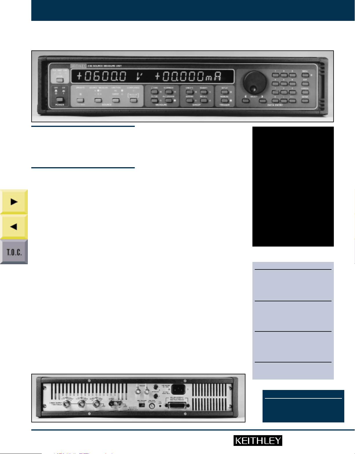
The 236, 237, and 238 Source-Measure Units (SMU)
are fully programmable instruments, capable of
sourcing and measuring voltage or current simultaneously. These systems are really four instruments
in one: voltage source, current source, voltage measure and current measure.
The 236 will source voltage from 100µV to 110V, and
current from 100fA to 100mA. It can also measure
voltage from 10µV to 110V and current from 10fA to
100mA. The 237 offers the same capabilities with a
decade enhancement in voltage source and mea-
QQZQ
QZQQ
QZZQ
sure (1100V). In this higher voltage range, current
source and measure is 10mA maximum. The 238
offers a decade enhancement in current source and
measure (1A). In this higher current range, voltage
source and measure is 15V maximum.
The 236, 237, and 238 will measure very small currents and voltages. With current sensitivity of 10fA,
measurement capabilities are equal to those of an
electrometer. Selectable integration and the filtering
of multiple measurements enhances sensitivity for
demanding applications.
Both source voltages and source currents settle to
specified accuracy in as little as 500µs. Programmable delay and fast, integrating measurement capability can provide coordinated source-measure
times of 1ms.
Applications
These instruments address a wide variety of applications, including the characterization of semiconductor devices, and the measurement of leakage
currents or resistivity. They are particularly useful as
source and measuring instruments in automated
test equipment (ATE).
The 236, 237, and 238 provide simple, accurate measurements in semiconductor applications. Multiple
units controlled with a personal computer make a
powerful semiconductor parameter analyzer. Nonstandard tests are also performed efficiently because of the unique versatility of these units.
Two accessory semiconductor test fixtures maintain
the signal integrity of the SMUs all the way to your
device. The 8006 is a general purpose test fixture,
and the 8007 is designed to accommodate either 24or 48-pin devices. These test fixtures can be safety
interlocked with the 236, 237, and 238 to prevent
accidental shock.
A Keithley Model 707A or 708A switching matrix
and semiconductor switching cards may be used in
conjunction with the 236, 237, and 238 for optimum performance in automated semiconductor
measurement applications.
Keithley SMUs are powerful tools for research and
industrial test applications. The short set-up time
and simplified programming are big advantages for
tests that need to be up and running quickly. The
overall versatility is ideal for constantly changing
research use.
The large dynamic range of source and measure
capabilities permits accurate measurement of insulation resistance, leakage current, and dissipation
factors. The high sensitivity of these units make
them ideal for characterizing the electrical properties of many materials.
Enhanced System Versatility
A single Source-Measure Unit eliminates most of the
complicated system integration problems involved
with setting up and programming individual sources
and meters. This new, compact module also saves
rack space and can be more economical than separate components.
New test systems can be developed much faster with
SMUs. There is only one set of device dependent commands (DDC) to learn, and the overall test system is
better coordinated for more efficient operation.
•Four instruments in one (voltage
source, voltage measure, current
source, current measure)
•10fA, 10µV measurement
sensitivity
•1100V source and measure (237
only)
•1A source and measure (238 only)
•Standard and custom sweep
capability including pulse
•1000 source/measurements per
second
•Four quadrant source operation
•Internal 1000-reading memory
ORDERING INFORMATION
236 Source-Measure Unit with two
7078- TRX-10 3-Slot Low Noise Triax
Cables, 3m (10 ft), one 236-ILC-3
Interlock Cable, 3m (10 ft), and one
237-ALG-2 Low Noise Triax Cable,
2m (6.6 ft)
237 High Voltage Source-Measure Unit
with two 7078-TRX-10 3-Slot Low
Noise Triax Cables, 3m (10 ft), one
236-ILC-3 Interlock Cable,
3m (10 ft), and one 237-ALG-2 Low
Noise Triax Cable, 2m (6.6 ft)
238 High Current Source-Measure Unit
with two 7078-TRX-10 3-Slot Low
Noise Triax Cables, 3m (10 ft), one
236-ILC-3 Interlock Cable,
3m (10 ft), and one 237-ALG-2 Low
Noise Triax Cable, 2m (6.6 ft)
These products are available with an
Extended Warranty. See page 635 for complete ordering information.
www.keithley.com
QUESTIONS?
1-800-552-1115 (U.S. only)
Call toll free for technical assistance,
product support or ordering information, or
visit our website at www.keithley.com.
149
Page 2
150
LOW-LEVEL SOURCES
236, 237, and 238 Source-Measure Units
Figure 1: Internal Memory
Rotary
Dial
STEP
0001
0002
0003
0004
0005
0028
1000
SOURCE
+1.0000 V
+02.000 V
+03.000 V
+04.000 V
+05.000 V
-
-
-
+028.00 V
-
+1000.0 V
ACCESSORIES AVAILABLE
CABLES
236-ILC-3 Interlock Cable, 3m (10 ft)
237-ALG-2 3-Slot, Low Noise Triax Cable,
7078-TRX-3 3-Slot, Low Noise Triax Cable,
7078-TRX-10 3-Slot, Low Noise Triax Cable,
7078-TRX-20 3-Slot, Low Noise Triax Cable,
RACKS & RACK MOUNT KITS
1938 Fixed Rack Mount Kit
1939 Slide Rack Mount Kit
8000-10 Equipment Cabinet, 10 in high
8000-14 Equipment Cabinet, 14 in high
SOFTWARE
Metrics-ICS
Metrics-ICS-IV/TestPoint
SWITCHING (page 174)
707A Switching Matrix
708A Switching Matrix
7072 Semiconductor Matrix Card
7072-HV High Voltage Semiconductor
7153 High Voltage Low Current Matrix
7172 8×12 Low Current Matrix Card
7174A 8×12 High Speed, Low Current
TEST FIXTURES
8006 Component Test Fixture
8007 Semiconductor Test Fixture
OTHER
213 Quad Voltage Source
237-TRX-NG 3-Slot Triax to 3-Lug Female
See page 235 for descriptions of all
accessories.
2m (6.6 ft)
0.9m (3 ft)
3m (10 ft)
6m (20 ft)
Matrix Card
Card
Matrix Card
Triax Connector
QUESTIONS?
1-800-552-1115 (U.S. only)
Call toll free for technical assistance,
product support or ordering information, or
visit our website at www.keithley.com.
Measurements as a Function of Voltage,
SELECT
DELAY
00.100 s
00.100 s
00.100 s
00.100 s
00.100 s
-
00.100 s
-
00.100 s
MEASURE
+1.0921 nA
+1.1526 nA
+1.2234 nA
+2.3725 nA
+2.7713 nA
-
+3.6576 nA
-
+8.5763 nA
000.002 s
000.003 s
000.005 s
000.006 s
000.008 s
-
000.042 s
-
001.503 s
Current, or Time
Measurements can be taken and recorded in an internal
memory along with corresponding values of the source voltage or current and time. Up to 1000 values of each variable,
correlated in time, may be accessed by the front panel using
either a rotary dial or a keypad. All measurement and source
values along with the elapsed time may also be obtained over
the IEEE-488 bus.
The internal memory is organized to obtain and present
measurement results in a versatile and easy to understand
manner. All source values and corresponding measurement
values are stored in sequence and share a common index.
Data Display
The contents of the internal memory may be accessed via the IEEE-488 bus or displayed in several formats using the front panel controls. Source and measure values may be displayed simultaneously or
with the index value. Delay and elapsed time may also be displayed with the index. The choice between
display modes is conveniently made using the Select keys. The delay time between source and measurement may be independently set from 0 to 65,000ms from the front panel or the IEEE-488 interface.
Selectable Sweeps of Voltage and Current
The 236, 237, and 238 may be programmed to perform source-measurements as a function of a stepped
voltage or current. Voltage and current may be swept linearly, logarithmically, or pulsed. The START,
STOP, STEP method of setting sweep parameters allows operators to become proficient at using the
instrument very quickly. Sweep parameters may be appended (APPEND key) to obtain more complex
test sequences.
Creating custom sweeps of voltage or current is facilitated by the use of three waveform operations: CREATE, APPEND, and MODIFY. These allow the user to select waveform parameters, combine multiple
waveforms, and select and change any points in a waveform previously created or appended.
Fully-Guarded Four-Terminal Measurements
The 236, 237, and 238 outputs and inputs are fully guarded, and the units are configured to allow fourterminal measurements. Two-terminal measurements are also available for more standard test procedures. These outputs may be floated up to ±200V from ground.
Source Capability
The 236, 237, and 238 deliver full output current at maximum voltage to allow for optimum characterization of high-power devices. The 236 delivers up to 100mA at 110V, the 237 delivers 10mA at 1100V, and
the 238 delivers 1A at 15V.
Suppression
Pushbutton suppression lets you make relative measurements with respect to a baseline or cancel background signals. Suppression for a particular measurement may be any value within the specified operating range of the instrument.
Fast, efficient programming makes these Source-Measure Units the ideal systems for a wide range of
testing procedures in the most comprehensive systems.
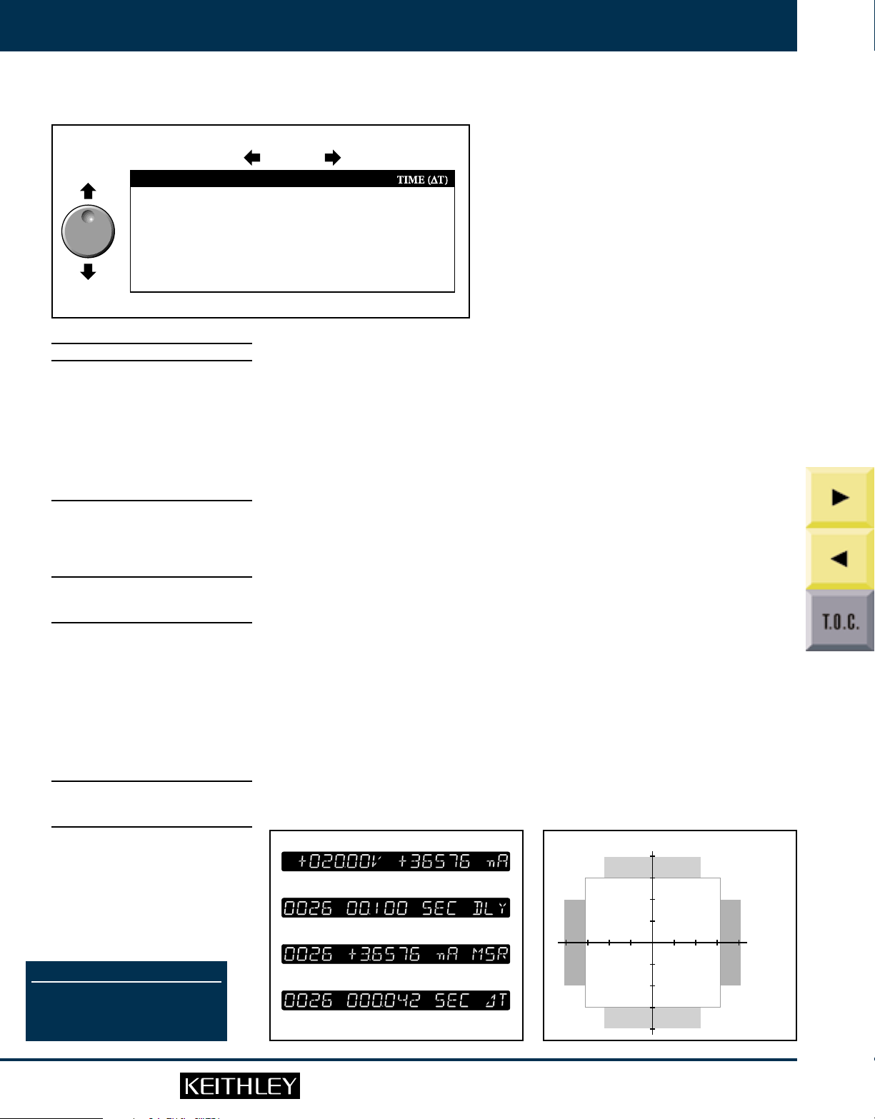
FIGURE 2: Data Displays FIGURE 3: SMU Source Capability
238:
±1A at ±15V
1A
Display source and measure values simultaneously.
Display delay time between source and measurement.
Display measured current.
Display time (∆T).
100mA
10mA
1mA
–1mA
–10mA
–100mA
–1A
236, 237, 238:
±110V,
±100mA
1V 10V 100V 1000V–1V–10V–100V–1000V
237:
±1100V at
±10mA
QQZQ
QZQQ
QZZQ
150
www.keithley.com
Page 3

LOW-LEVEL SOURCES
Default
Delay
Delay
Measure
Integration Time
Source
Value
Source-Delay-Measure Cycle
B
236, 237, and 238 Source-Measure Units
SOURCE-MEASURE UNIT: Sources voltage while measuring current, or
SWEEP WAVEFORMS DESCRIPTION
LEVEL, COUNT (number of DELAYMEASURE cycles), DELAY, BIAS
Bias
Delay
Fixed Level
Meas.
Delay
Meas.
Level
Bias
sources current while measuring voltage.
FUNCTION: Can be used as DC source or meter, sweep source, or full
source-measure unit.
SOURCE-DELAY-MEASURE CYCLE:
151
Step
Start
Bias
Linear Stair
Start
Logarithmic Stair
t
offton
Level
Pulse
Step
Start
Bias
Linear Stair Pulse
Start
ias
Logarithmic Stair Pulse
Stop
Bias
Stop
BiasBias
BiasBias
Stop
Bias
Stop
Bias
START, STOP, STEP, DELAY, BIAS
START, STOP, POINTS/DECADE (5, 10, 25,
or 50), DELAY, BIAS
LEVEL, COUNT, TON, T
START, STOP, STEP, TON, T
START, STOP, POINTS/DECADE (5, 10, 25,
or 50), TON, T
OFF
, BIAS
WAVEFORM
OPERATORS DESCRIPTION
Allows selection of waveform
parameters. Generates all source
values.
OFF
, BIAS
, BIAS
OFF
Default Delay: Fixed delay for instrument settling.
User Delay: Additional delay for device under test or system
capacitance.
MEASURE:
Integration Time
Fast 416 µs 4-digit resolution
Medium 4 ms 5-digit resolution
Line Cycle 16.67 ms (60 Hz) 5-digit resolution
20.00 ms (50 Hz)
Elapsed Time: Measures and stores time from sweep trigger to mea-
surement complete for each step of sweep.
RANGING:
Source: Auto-ranging through keypad entry; fixed range selection
using rotary dial and SELECT keys (DC function). Fully programmable in SWEEP function.
Measure: Auto or fixed range. Fixed range selection made by choice
of COMPLIANCE value.
FILTER:Takes n measurements, calculates and outputs average (n = 2, 4,
8, 16, or 32, selectable).
SUPPRESS: Subtracts displayed measurement from subsequent read-
ings.
MENU: DC Measurement Delay, Default Delay On/Off, Local/Remote
Sense, 50/60Hz, IEEE Address, Self Tests.
DATA ENTRY: Numeric keypad or detented rotary dial.
TRIGGER:
Input and Output: Set for any phase of SOURCE-DELAY-MEASURE
sequence or trigger output at end of sweep.
Origin: Internal, External (including front panel MANUAL TRIGGER
button), IEEE-488 bus (TALK, GET, “X”).
MEMORY: Stores one full sweep (up to 1000 points) of source, delay, and
measure values, elapsed times, and sweep parameters. Lithium battery backup.
INTERLOCK: Use with test fixture or external switch. Normally closed;
open puts instrument in standby.
Create
Combines multiple waveforms and
adds new points to those already in
memory.
Append
Select and change any points in a
previously created (or appended)
waveform.
product support or ordering information, or
Modify
www.keithley.com
QUESTIONS?
1-800-552-1115 (U.S. only)
Call toll free for technical assistance,
visit our website at www.keithley.com.
151
Page 4

152
LOW-LEVEL SOURCES
236, 237, and 238 Source-Measure Units
EXECUTION SPEED
MINIMUM SOURCE-DELAY-MEASURE CYCLE TIME: 1ms.
RESPONSE TO IEEE-488 COMMAND (as a source): 25ms.
MEASUREMENT RATE: 1ms per point into internal buffer.
CONTINUOUS MEASUREMENT SPEED (source DC value over
IEEE-488 bus): 110 readings per second.
TRIGGER LATENCY TIME: <2ms.
IEEE-488 BUS IMPLEMENTATION
MULTILINE COMMANDS: DCL, LLO, SDC, GET, GTL, UNT, UNL,
SPE, SPD.
UNILINE COMMANDS: IFC, REN, EOI, SRQ, ATN.
INTERFACE FUNCTIONS: SH1, AH1, T6, TE0, L4, LE0, SR1, RL1, PP0,
DC1, DT1, C0, E1.
All front panel functions and setups are available over the IEEE-488
bus, in addition to Status, Service Request, Output Format, EOI,
Trigger, and Terminator.
IEEE-488 address is set from the front panel menu.
GENERAL
LOAD CAPACITANCE: Stable into 20,000pF typical.
REMOTE SENSE: Corrects for up to 2V drop in each output lead.
Maximum 1kΩ per sense lead for rated accuracy. Residual output
resistance (as a voltage source) is 0.5Ω.
GUARD: Output Resistance: ≤12kΩ.
Maximum Output Current: ±2mA.
Offset Relative to Output HI: ±2mV max.
ISOLATION (Output LO to chassis): Typically >10
500pF (650pF on Model 238).
MAXIMUM COMMON MODE VOLTAGE: 200V.
CONNECTORS: Outputs: 3-lug triax.
Trigger Input/Output: BNC.
Interlock: 3-pin miniature DIN.
TEMPERATURE COEFFICIENT (0°–18°C & 28°–50°C): ±(0.1 × appli-
cable accuracy specification)/°C.
ENVIRONMENT:
Operating: 0°–50°C, 70% relative humidity up to 35°C. Linearly der-
ate 3% RH/°C, 35°–50°C.
Storage: –25° to 65°C.
EMC: Conforms to European Union Directive 89/336/EEC.
SAFETY: Conforms to European Union Directive 73/23/EEC (meets
EN61010-1/IEC 1010).
WARM-UP: One hour to rated accuracy.
COOLING: Internal fan forced air cooling.
POWER: 105–125 or 210–250V AC (external switch selectable), 90–
110V and 180–220V version available. 100VA max. (120VA max. on
Model 238).
DIMENSIONS, WEIGHT: 89mm high × 435mm wide × 448mm deep
1
(3
⁄2in × 171⁄8in × 175⁄8in). Net weight 9kg (19.75 lb).
QUESTIONS?
1-800-552-1115 (U.S. only)
Call toll free for technical assistance,
product support or ordering information, or
visit our website at www.keithley.com.
10
Ω in parallel with
VOLTAGE
236, 237 ±1.1000 V
237 Only ±1100.0 V 100 mV ±(0.04 % + 240mV) 100 mV 10 mV ±(0.035%+100mV )
238 Only ±1.5000 V 100 µV ±(0.033% +800 µV 100 µV 10 µV ±(0.028% + 450µV
IO= Output current; IFS= Full scale on selected current range
1
Specifications apply for 5-digit resolution. For 4-digit resolution add 100ppm of range.
2
Assumes remote sense for I > 100µA.
3
On the 1A range use [IO/IFS] × 250µV.
COMPLIANCE: Bipolar current limit set with single value.
Maximum: ±100mA (except ±10mA on 1100V range in Model 237 and ±1A on 15V range in Model
Minimum: ±1% of range, except 0.5% of 1.1V range.
Accuracy,Step Size: Same as current source.
NOISE (p-p):
1.1 V (1.5V on 238) <10ppm of range 15 mV
WIDEBAND NOISE: 0.1 to 20MHz, 8mV p-p typical.
OVERSHOOT: <0.01% (110V step, 10mA range).
SETTLING TIME: <500µs to 0.01% (110V step, 10mA range).
NMRR: >60dB at 50 or 60Hz (LINE CYCLE integration time selected).
CMRR: >120dB at DC, 50 or 60Hz (LINE CYCLE integration time selected).
INPUT IMPEDANCE (as a voltmeter): >10
RANGE ACCURACY ACCURACY
(Max. STEP (1 Year, RESOLUTION (1 Year,
Value) SIZE 18°–28°C) 4-Digit 5-Digit 18°–28°C)
±11.000 V 1 mV ±(0.033% + 2.4mV ) 1 mV 100 µV ±(0.025%+ 1mV)
±110.00 V 10 mV ±(0.033% + 24mV ) 10 mV 1 mV ±(0.025%+ 10mV )
±15.000 V 1 mV ±(0.033% + 2.7mV) 1 mV 100 µV ±(0.025%+ 1mV)
±110.00 V 10 mV ±(0.033% + 24mV ) 10 mV 1 mV ±(0.025%+ 10mV )
238).
RANGE 0.1–10Hz DC–20MHz
110 V – 1100 V < 3ppm of range 40 mV
11 V (15 V on 238) < 3ppm of range 15 mV
CURRENT SOURCE I MEASURE I
RANGE ACCURACY ACCURACY
(Max. STEP (1 Year, RESOLUTION (1 Year,
Value) SIZE 18°–28°C) 4-Digit 5-Digit 18°–28°C)
All ±1.0000 nA 100 fA ±(0.3 %+ 450 fA) 100 fA 10 fA ±(0.3 % + 100 fA)
±10.000 nA 1 pA ±(0.3 %+ 2 pA) 1 pA 100 fA ±(0.3 % + 1 pA)
±100.00 nA 10 pA ±(0.21%+ 20 pA) 10 pA 1 pA ±(0.21 % + 6 pA)
±1.0000 µA 100 pA ±(0.05%+ 200 pA) 100 pA 10pA ±(0.04 % + 6 pA)
±10.000 µA 1 nA ±(0.05%+ 2 nA) 1 nA 100 pA ±(0.035% + 700 pA)
±100.00 µA 10 nA ±(0.05%+ 20 nA) 10 nA 1 nA ±(0.035% + 6 nA)
±1.0000 mA 100 nA ±(0.05%+ 200 nA) 100 nA 10 nA ±(0.035% + 60 nA)
±10.000 mA 1 µA ±(0.05%+ 2 µA) 1 µA 100 nA ±(0.038% + 600 nA)
238 Only ±1.0000 A 100 µA ±(0.12%+ 700 nA) 100 µA 10µA ±(0.12 % + 300 µA)
1
2
COMPLIANCE: Bipolar voltage limit set with single value.
NOISE (p-p of range): 0.1–10Hz: <3ppm (<20ppm on 1nA and 10nA ranges and on 1A range in
OVERSHOOT: <0.01% typical (10mA step, R
SETTLING TIME: <500µs to 0.01% (10mA step, R
OUTPUT R, C: >10
±100.00 mA 10 µA ±(0.1 %+ 20 µA) 10 µA 1 µA ±(0.1 % + 6 µA)
Specifications apply for 5-digit resolution. For 4-digit resolution, all offset terms are 200ppm of range.
Offset specification applies for 23°C ± 1°C with suppression. Temperature coefficient 50fA/°C.
Maximum: ±1100V (except ±110V in Model 238 and on 100mA range in Model 237).
Minimum: ±0.1% of selected current range.
Accuracy,Step Size: Same as voltage source.
Model 238).
SOURCE V MEASURE V
2
100 µV ±(0.033%+650 µV 100 µV 10 µV ±(0.028% + 300µV
14
Ω paralleled by <20pF (on 1nA range).
+ [IO/IFS] × 450µV) + [IO/IFS] × 450µV)
= 10kΩ).
= 10kΩ).
L
3
+ [IO/IFS] × 600µV)
+ [IO/IFS] × 600µV)
14
Ω paralleled by <20pF.
L
1
1
QQZQ
QZQQ
QZZQ
2
152
www.keithley.com
 Loading...