

Page 1
KE1TH
LEY
1
NSTRUMENTS
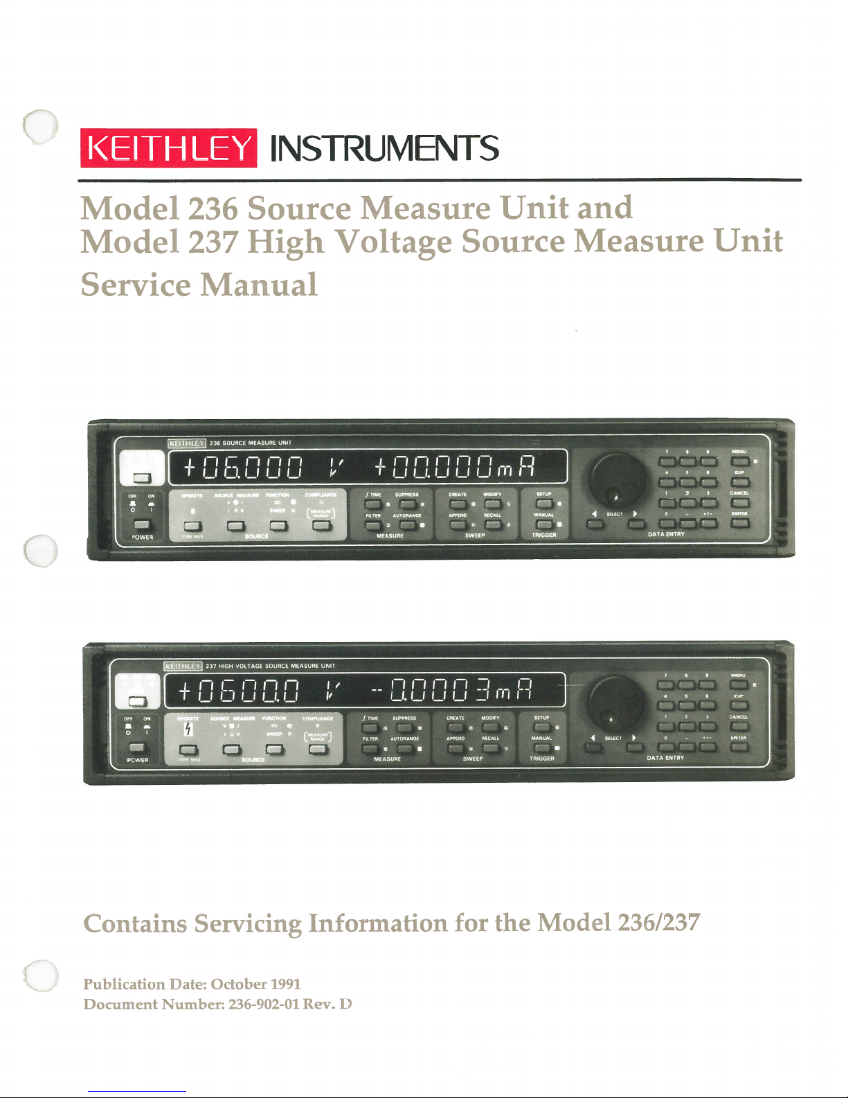
Model
Model
Service
236
237
Source
High
Manual
Measure
Voltage
i
Unit
Source
and
Measure
Unit
Contains
Publication
Document
‚
1
T
Ij
Servicing
Date:
October
Number:
F
fl
LI
r
Lt
U
1991
236-902-01
‘
fl
u
i
ii
Information
D
Rev.
n
UI
ri
LILIU
n
for
_I
j
rn
the
o
i
i
Model
236/237
Page 2
Keithley
period
Instraments,
year
of
1
from
Inc.
date
warrants
shipment.
of
this
WAR
product
RANTY
tobefree
from
defects
in
material
and
workmanship
for
a
Keithley
Instruments,
rechargeable
During
the
fective.
To
exercise
Cieveland,
prepaid,
tion
prepaid.
least
This
ten
Repaired
days.
90
warranty
consent,
chargeable
instructions.
WARRANTY
THIS
IMPLIED
ANY
REMEDIES
batteries,
warranty
warranty,
this
You
Ohio.
indicated
to
the
or
not
does
or
misuse
batteries,
WARRANTY
PROVIDED
Inc.
diskettes,
period,
will
replaced
apply
of
damage
IN
15
warrants
we
write
given
be
service
products
to
product
any
from
LIEU
HEREIN
following
the
documentation.
and
our
at
your
facility.
are
option,
local
assistance
Repairs
warranted
will,
or
call
prompt
LIMITATION
defects
OF
OF
resulting
part.
leakage,
OTHER
This
or
battery
ALL
MERCHANTABILITY
BUYER‘S
ARE
for
items
either
Keithley
OF
from
90
repair
representative,
and
return
for
be
made
the
will
WARRANTY
product
warranty
problems
or
WARRANTIES,
OR
AND
SOLE
days
from
or
replace
instructions.
and
balance
modification
also
does
arising
EXPRESSED
FTTNESS
EXCLUSIVE
the
or
the
of
not
from
date
any
contact
product
the
apply
FOR
shipment:
of
product
Keithley
the
Send
retuined,
original
without
normal
warranty
Keithley‘s
to
fuses,
wear
TMPLIED,
OR
PARTICULAR
A
REMEDIES.
that
proves
headquarters
product,
software,
failure
or
probes,
cables,
be
to
transporta
transportation
period,
express
or
writ
non-re
follow
to
INCLU1JIMG
THE
USE.
de
in
at
NEITHER
DIRECT,
AN
USE
THE
OF
BEEN
ADVISED
SHALL
AGES
LOSSES
SUSTAINED
KEITH
Instruments
AUSTRIA:
FRANCE
GERMANY:
GREAT
BRITAIN:
ITALY:
JAPAN:
NETHERLANDS:
SWITZERLAND:
TAIWAN:
KEITHLEY
INDIRECT,
ITS
OF
IN
INCLTJ1JE,
LEY
Division,
Keithley
Keithley
Keithley
Keithley
Keithley
Keithley
Keithley
Keithley
Keithley
INSTRUMENTS,
SPECIAL,
INSTRUMENTS
ADVANCE
BUT
THE
AS
Instruments
Instruments
Instruments
Instruments,
Instruments
Instruments
Instruments
Instruments
Instruments
Instruments,
GesmbH
SARL•3
GmbH
Ltd.
SRL
Far
BV
SA
Taiwan
Keithley
OF
ARE
RESULT
Rosenhugeistrasse
•
Allee
•
Landsberger
Minster•58
•
The
•
Viele
S.
•
East
KK
•
Avelingen
•
Kriesbachstrasse
•
Room
INC.
INCIDENTAL
SOFTWARE
AND
POSSIBILITY
THE
LIMITED
NOT
INJURY
OF
28775
•
Inc.
BP.
•
Garays
des
Gimignano
Sumiyoshi
West
1105,
Str.
65
Portman
38
24
49•4202
4
•
8600
Floor,
llth
•
•
Bldg.,
NOR
Aurora
A-1J20
12
•
•
60
D-8034
Road
20146
Room
Gorinchem
MS
Dubendorf
No.
ANY
T0
Road
91121
Germering
Reading,
•
Milano
201
147
•
ITS
OF
CONSEQUENTIAL
OR
IF
EVEN
SUCH
OF
COSTS
TO:
PERSON,
ANY
•
Cieveland,
•
0222-804-6548
Wien
Palaiseau
•
02-48303008
2-24-2
•
•
Postbus
•
01-821-9444
Section
•
Berkshire
Cedex
089-849307-0
•
Sumiyoshi-Cho
559
Fax:
•
2,
Chien
•
RG3
Fax:
4200
•
01-820-3081
Kuo
EMPLOYEES
KEITHLEY
DAMAGES.
REMOVAL
OF
DAMAGE
OR
44139•(216)
Ohio
Fax:
0222-804-3597
•
01-60-11-51-55
Fax:
•
1EA•0734-575666
02-48302274
AN Gorinchem
North
089-84930759
Naka-Ku,
•
•
Road
Fax:
•
Taipei,
SHALL
BE
DAMAGES
INSTRUMENTS,
SUCH
EXCLUDED
INSTALLATION,
AND
TO
81-45-201-2246
•
231
•
R.O.C.
•
Fax:
•
886-2-509-4-465
01-60-11-77-26
Fax: 0734-596469
•
Yohohama
•
01830-35333
Taiwan
248-0400
LIABLE
ARISING
INC.,
DAM
PROPERTY.
(216)
•
248-6168
Fax:
81-45-201-2247
Fax:
•
Fax:
01830-30821
FOR
01ff
HAS
886-2-509-4473
Page 3
Service
Manual
Model
Model
237
High
236
Voltage
Source
Measure
Source
Unit
Measure
Unit
.
%
Rlght$
Instruments,
Reserved
Ohio,
01990,
.
.
Keitbley
AU
.
hsträmen6DfrIson•
cieveland,
DocumentNnbec236-902-O1
U. S.
Inc.
A.
Page 4

All
Keithley
Other
brand
products
and
product
are
trademarks
names
are
trademarks
or
registered
trademarks
or
registered
of
Keithley
trademarks
Instruments,
their
respective
of
Inc.
holders.
Page 5
BESCHEINIGUNG
DES
HERSTELLERS/IMPORTEURS
etwirdbescheinigt,(da3)/dasMODEL
mit
dieses
Bestimmungen
den
Gerates
angezeigt
der
und
Vfg
die
geraumt.
Einhaltung
Die
Fur
DIESES
ANWENDUNGSFALL
GEPRUEFI
UNGUENSTIGEN
WERDEN.
J
Beschaffung
die
DER
Keithley
der
GERAET
EST
HiER
DIE
DIESES
GERAET
Instruments,
betreffenden
richifger
WURDE
Me1eitungen
SOWOHL
NACHBILDET,
IS
JEDOCH
UMSTAENDEN
EJHALTUNG
BETRIEBEN
Incorporated
CERTIFICATE
1046/1984
Berechtigung
funkentstort
BesUnimungen
ist
ELN
AUF
MOEGUCH,
BEI
ANDEREN
DER
FUNKENTSTOERBEST1UNGEN
WWD,
23
6/237
zur
setzt
der
Befreiber
DIE
IST
BY
MANUFACTURER/IMPORTER
/238
ist.
Uberprufung
vordus,
ALS
AUCH
EHALTUNG
DASS
GERAETEKOMBIATIONEN
DER
SOUCE
Der
Deutschen
der
Serie
da,
(dass)
geschirmte
verantworificK
EllER
DER
D
FUNKENTSTOERBEST1UNGEN
BETREIBER
MEASURE
Bundespost
auf
VERANTWORTLICH.
UNIT
wurde
Einhaltung
Me1eitungen
ANLAGE,
FUNKENTSTOERBESTfUNGEN
DIE
SER
inUbereinsümmung
das
Inverkehrbringen
der
Bestimmungen
verwendet
EEN
NICHT
GESAMTEN
E1GEHALTEN
NORMALEN
ANLAGE,
ein
werden.
UNR
istocerUfy
This
accordancewith
in
ence
is
ifons.
Compliance
curing
nils
TION
TION
put
being
the
EQUIPMENT
REQUIREMENTS
CONDITIONS).
CERTAIN
BLE
FOR
Keithley
that
the
the
on
the
market
with
applicable
appropriate
and
cables.
HAS
Born
HOWEVER,
UNFAVORABLE
COWLIANCE
Insfruments,
provisions
that
they
regulations
BEEN
TESTED
INDWIDUALLY
lT
CONDITIONS
OF
HIS
PARTICULAR
Incorporated
ofVfg
1046/1984.
have been
depends
CONCERNJG
IS
POSSIBLE
R
The
given
the
on
the use
AND
ON
THAT
OTFR
STALLATIONS.
STALLATION.
GermanPostal
right
of
COWLIANCE
THESE
inspect
to
shielded
SYSTEM
RFI
cables.ltis
i
Services
the
WITH
LEVEL
REQUIREMENTS
lT
series
the
(TO
IS
havebeen
for
user
THE
SIULATE
THE
shielded againstradio
advised
compliance
who
is
RELEVANT
thatthis
with
responsible
RFI
NORMAL
NOT
ARE
USER
WHO
MET
IS
RESPONSI
interfer
device
regu1a
the
for
PROTEC
OPERA
UNDER
pro
Page 6

Page 7

The
The
are
famifiar
before
following
Model
using
safety
236/237
with
the
instrument.
precautions
Source
the
safety
SAFETY
should
Measure Unit
precautions
observed
be
is
intended
requiredtoavoid
PRECAUTIONS
before
for
using
Model
usebyqualified
possible
injury. Read
236/237
personnel
over
Source
who
the
Measure
recognize
Operator‘s
Units
shock
manual
hazards
carefully
and
Exercise
Measure
voltagelevels
is
lnspect
For
power
necting
eration
Do
(earth)
standing
Do
tions
present
the
maximum
is
cables
requires
not
touch
ground.
not
exceed
and
extreme
Unit
in
applied
the
operation
caution
connector
greater
any
unknown
connecting
safety,
to
the
orjumpers.
the
any
object
Always make
voltage
the maximum
when
jacks.
than
30V
circuit
cables,
do
not
circuit
Also,
useofthe
which
being
measured,
section
a
shock
hazardispresent.
The
American
RMS
or4Z4Vpeak
before
test
touch
under
keep
lid
interlock.
could
measurementswith
signal
of
the
instruction
leads,
the
test.
the
provide
levels
measuring.
and
Source
Turn
test
of
National
arc
jumpers
Measure
off
all
fixture
a
current
dry
the
test
manual.
Lethal
voltages
Standards
present.
for
Unit,
power and
lid
closed
pathtothe common
hands
fixture,
A
possible
test
while
while
shown
as
Institute
good
wear,
discharge any
standing
maybepresent
(ANSI)
safetypractice
cracks,orbreaks
fixture,
power
on
test
is
sideofthe
on
the
rear
on
states
thatashock
istoexpect
before
cablesorany
capacitors before
appliedtothe
circuit
a
dry,
insulated
panel
and
the test
fixture
thathazardous
each use.
other
connecting
device
as
under
under
surface
definedinthe
or
the
hazard
instruments
exists
or
test.
testorpower
capable
Source
when
voltage
while
discon
Safe
op
line
of
with
specifica
Connect
Instrumentation
The
Operator‘s
When
PUT
hazard,
test
the
symbolon
a
Model
terminals
always
fixture.
Manuals
236/237
when
turn
screw
and
accessories
a
Model237
for
the
offall
of
the
test
indicates
detailed
is
programmed
unitisin
power
fixftire
should not
operation
operate
before
to
safety
be
connectedtohumans.
that
1000V
information.
for
remote
regardiess
connecting
earth
ground using
or
more
sensing,
of
the
or
disconnecting
may
be
presentonthe
hazardous
programmed
cables to
#18
voltage
voltage
AWG
may
the
or
larger
terminals.
be
present
or
current.
Source
wire
(supplied
Refer
to
on
the
To
avoidapossible
MeasureUnit
accesso).
the
Mode1236/237
SENSE
or
and
the
associated
OUT
shock
Page 8

Page 9
PRCAUTIONS
Ii
faut
observer
pareils
Lappareildemesuredesourcedumod1e
par
et
des blessures
dutiliser
Ii
tion.
test
Linstitut
ddlectrocution
pointe
dre
Avant
cordons dc
cass6s.
Pour
dc testoules
connecteur
tre sur
avantdcbrancher
maintenir
pareiL
danger.
Ne
cöt6
toujours
face
Ne
mc
donn6es
Les
personnes.
Le
pr6sents
Avec
peut
Cette
circuits
tion
d&ecteur
sion.11faut
sources
Pour
tous
mesure
de
personnes
des
familires
sont
faut
ou
ä
pas
pas
montr6
instrumentsetles
symbole
possibles.IIfaut
linstrument.
faire
extr8mement
tensions
Des
les
dans
National
sont
prdsentes.
des
tensions
chaque
test
le
maximumdcs6curitd,nepas
cäbles
d‘instrument
1‘arrt
toutes
ferm6
Ii
verrouiller
laut
toucher
communducircuitäessayer
sacheetisol6e
les
faire
d6passer
surlepanneau
techniques
dans
les
le
dtecteur
produire
tension
peut
extrieurs.Iifaut
soient
correctement
loign.
sassurer
externes
les
dispositifsdctestäplusieurs
les
modles
SOMMAIRE
LOCAL
(LOCAL):Met
fonctionnement
GROUPE
OPERATION
ou
MESURE
mesure
FONCTION
ouenbalayage.
DE
(OPERATE):Met
dattente.
SOURCE
lintensit6ouchoisit
(PUNCflON):choisit
DE
SCURIT
les
pr&autions
de
source
qualifi6es
avec
les
mortelles
fichesdcconnecteursdelappareildemesuredcsource.
Amricain
quand
des
Une
dangereuses
utilisation,iifaut
les
et
fils
dc testdclappareildcmesuredcsourceoutout
les
alimentations
ou
ddbrancher
le
couvercledudispositif
nimporte
mesures
capabledcsupporterlatension
les
niveaux
et
des
accessoires
sur
le
mod6le
terminaux.
loign
tensions
des
causer
JAMAIS
NE
dalimentation.
236/237/238 soit
DES
touchesdupanneau
des
SOURCE
(SOURCE MEASURE):Choisit
s&urit
de
236/237/238.
qui reconnaissent
pr6cautions
lirelemanuel
attention quand
peuvent
tensions
bonne habitude
dc
quand
le
couvercle
quel
avec
maximumdcsignauxdclinstrument,
arri6reetcomme indiqu6
op6rations
237
en
des
toujours
branchs
toujours
de
de
8tre
Normes
des
sup6rieuresä30VRMS
avantdcmesureruncircuit
v6rifier
connexion
des
marche,uncordondedtection
morteilesäOUTPUT
blessuresoula
que
toucher
le
circuitäessayer est
et d6charger
les
cäblesoules
pour
qui
objet
la
ou ä
mains
du
ne doivent
indique
s‘assurer
avantdcmete
changer
d&harger
appareils
tous en
COMMANDES
lappareilenfonctionnement
lappareilenpositiondcfonctionnement
lintensit6
dc
fonctionnementencourant continu
le
suivantes
s6curitd
ne
pourrait
masse
s6chesense
manueldclinstrument.
que
frontal.
avant
236/237/238
les
risques
ndcessaires
de
l‘opdrateur
ii
pr6sentes
(ANSI)
dc test
les
marcheousoit
la
risques
a
des
y
dansledispositif
dit
quil
de
s&urit
les
cäblesdcconnexion,
soient
pas
les
connecteurs,
sous
les
tous
fils.Iifaut
pendant
obtenir
une
fournirunpassage
lalimentation.
dc
tenant
mesurer.
ä
danslasection
pas
8tre
branchds
1000Vou
sourceetmesure
plus
HI
mortetendommager
les
cordons de
que
branchements
et/ou
verrouill6s,iilaut
localetr6tablit
tensiondcsource
la
dutiliser
doit
d6lectrocution
avec
y
ou
est
us6s,
tension.
condensateurs
le
utilisation sans
peuvent
et GUARD.
en
dbrancher
tous
les
tre
utilis6
pour
6viter
soin
avant
d6lectrocu-
un
risque
a
42,4
V
satten-
dc
inconnu.
fissur6s
dispositif
le
autre
Met-
aussi
lap
test dc
Ii
faut
sur
une
sur
com
sur
tre
ouvert
dtec
marche
sous
ten
garder
arr8tds.
la
tension
ap
de
dc
les
ou
des
des
les
les
le
CONFORMIT1
mesurelaplage.
mutateur
GROUPEDEMESURES
TEMPS
taelleenappuyant
ENTER.
SAUVEGARDE
lignedcbase.
supprim6eetle
FILTRE
ifitrationenappuyant
dc
AUTOPLAGE
aveclaplus
plage
GROUPE
CREER
les
boutonsdcSELECT
sur
ENTER.
balayageetle
dc
MODIFIER
pointsdcbalayage
balayage,
le
d6lais
sourceachang6
plagedcla
AJOUT
au
sur APPEND
boutons
ENTER.
balayageetle
PAPPEL
mesuresetla
mutateur
les
avantdcfaire
GROUPE
PRIPARATION
commutateur
le
et ENTER
MÄNUEL
tant
puyer
bus
GROUPE
le
Commutateur
fonctionnement,
en
CHOIX
mentdcremplacement
des
Clavier
les
le
MENU
dc
dimplicite
lalimentation
Aussi
et
param6tres.
indique
surlebouton
IEEE-488ouune
RECALL
donnes
donn6es
fonctionnement:
utilisd
(COMPLIANCE):Vdrifie
Changerleniveau
rotatifoule
(TIME)
(FILTER)
DE
(CREATE)
Utiliser
(MODIFY):Affiche
les
clavier
source.
(APPEND)
SELECT
Utiliserlecommutateur
(RECALL)
rotatif
DE
pour
(MANUAL)
D‘ENTRE
(SELECT):Ccs
dc
:
Toutes
num6riques.
(MENU)
(marche/arrt(
pour
ciavier
V6rifielap6riode
:
sur
les
(SUPPRESS):Sauvegarde
lectures suivantes
Les
niveau
r6el
Affiche
:
sur
(AUTORANGE)
grande
sensibilitd
BALAYAGE
Choisitunbalayageetd6finit
:
pour
le
commutateur
clavier
pour
sauvegard6s. Utiliser
boutons
fait
quune
rotatif
commande
SELECT
et ENTER
utffiser
les
Ajouteunbalayageäun
:
afficherlebalayage
pour changerletype
ciavier
pour
Affiche
:
pour
dur6e
choisirlepointetles
pour
Affiche
seulement
balayage.
le
DCLENCHEMENT
(SETUP):V6rifie
rotatif
pour
changer
les
:
Le
stimulationdcd6clenchement
MANUAL,
entr6e
DE
Commande
:
r6gle
les
valeurs
laffichage
boutons
et
balayage.
touchesduclavier
les
pour
Utilis6
:
d6lais
Hz/60
faire
Hz(
les
(50
actueletla
ensuite
dint6gration.
boutons
du
ldtat
les
changer
pour
boutons
les
chaque
afficher
param6tres.
voyantdcd6clenchement
quandenRECALL,
du
auto-tests,
dc
seront
signal.
ifitre
du
boutons
:
Permet
pour
le
rotatif
les
changer.
les
valeursdcla
pour
changer
SELECTetENTER
actuel
rotatif
changer.
les
paramtresdcla
pointdcbalayage.
les
l6tat
les
une commandedcddclenchement
externedcd6clenchement(.
DONNES
laffichagedcdiffdrents
la
dc
des
choisissent
vdrifier
ou
courant
ddtection
ladresse
et
niveaudcconformit
plage
appuyer
sur
SELECT,
la
conversion
la
diff6rence
mesure.
dc
SELECT
dc
lappareildcse
ä
faire
une
balayage,
type
dc
pour
bouton pour
le
la
choisir
valeurs.Sila
les
balayage
et
ses
balayage,
dc
afficher
pour
boutons
valeursdclii
actuel
du
paramtres
source
et
dc
donn6es dc
paramtres
les
commandent
(sauf
MENU(
changer
continu
(0ä65
(locale/loign6e(
IEEE-488(0ä
en
utilisantlecom
ENTER.
Changer
valeurdcsourceetdc
d6clenchement,
la
s6lection
ensuite
appuyer
suivante comme
entrelavaleur
Changer
ensuite
sur
mettre
mesure.
param6tres.
ses
ensuite
afficher
les
paramtres
sourceetdc
choisirlepoint
valeurdcla
pour
existant.
param6tres.
source,
SELECT
conformitd et
les
appuyer
ensuite
les
param6tres
les
valeurs
Utiliser
pour
source et
les
touches
MANUAL
est n6cessaire
param6tres dc
balayage.
dc
fonctionne
entrentouannulent
conditions
secondes(
frquence
30
lii
quantit6
ENTER.
dans
Utiliser
appuyer
ddlais
changer
Appuyer
Utiliser
com
le
afficher
d6lais
du
Utiliser
SELECT
digno
(ap
sur
quand
laffichage
suivantes
d6lais
secondes(.
et
ac
sur
la
des
dc
la
les
sur
dc
des
le
dc
Page 10
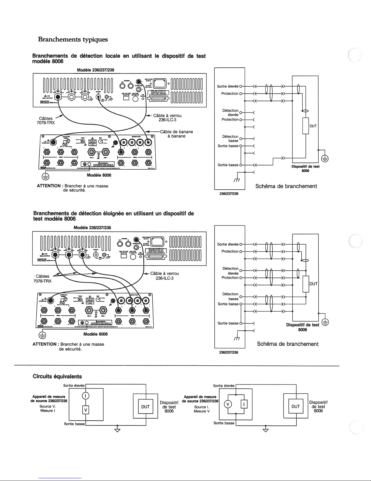
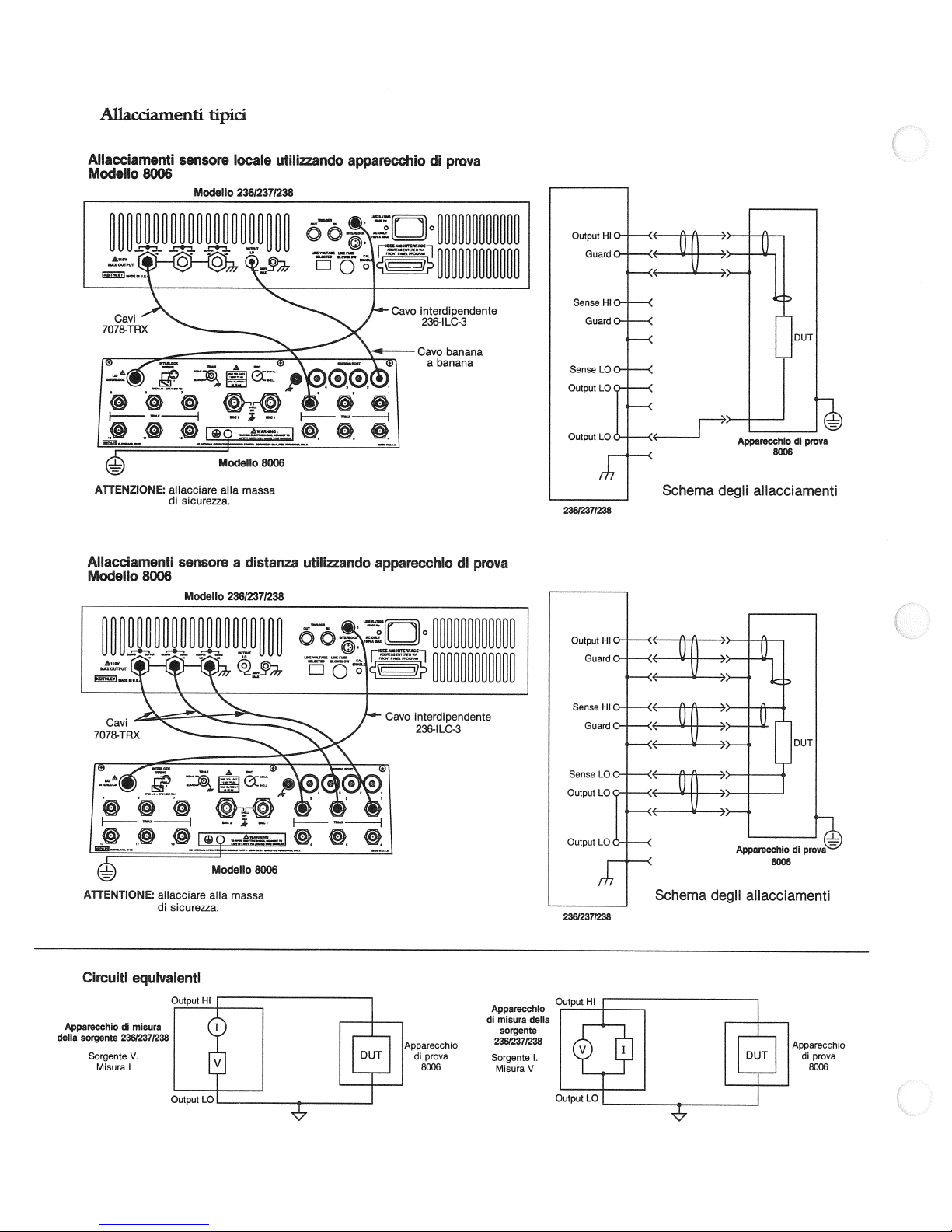
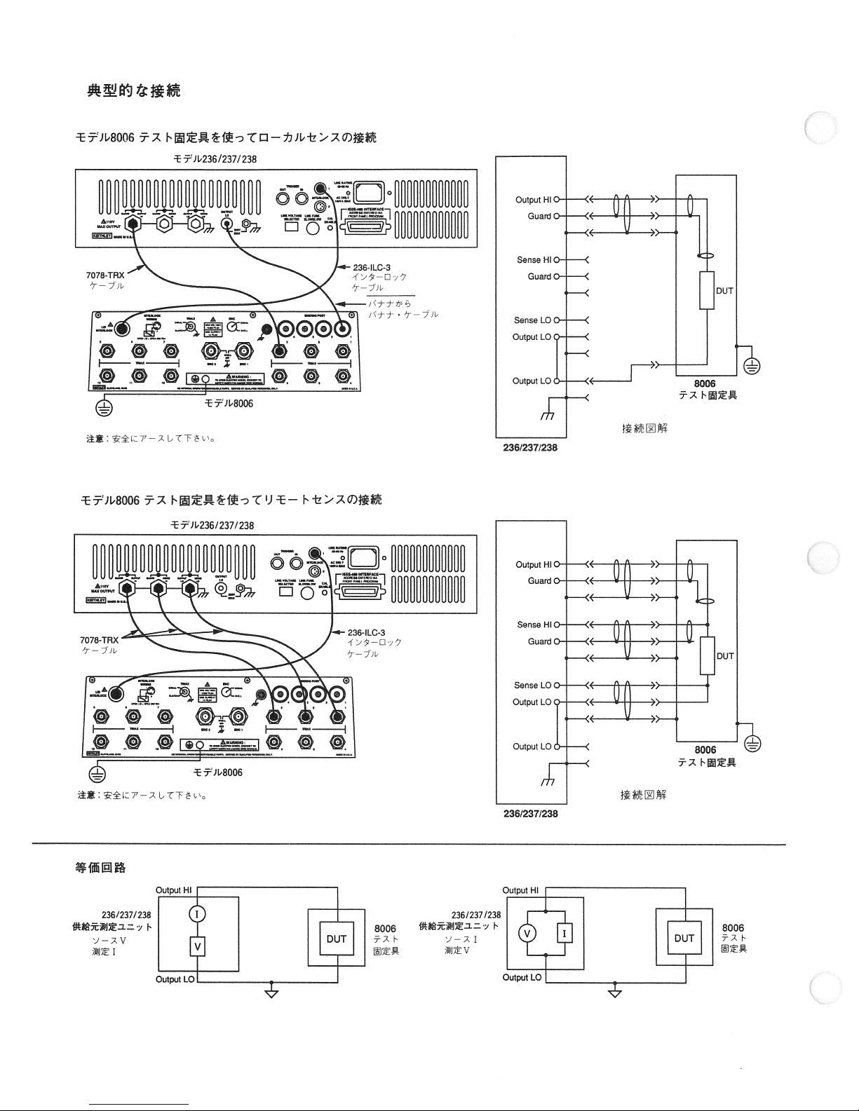
Branchements
typiques
Branchements
mod&e
8006
r•
—.
7o;8-TRx
c»
F—
ATTENTION
Branchements
mod&e
test
de
0
:
Brancher
de
scurit.
de
8006
dtection
ModIe
—
dtection
Mode
23812371238
0
A
Modele
une
masse
23612371238
locale
8006
Ioigne
en
ÖÖ
f—
utilisant
en
—
utlUsant
le
ri
Cäble
236-ILC-3
Cäbledebanane
0
un
dispositif
ä
verrou
äbanane
dispositif
de
de
test
23612371238
Schma
branchement
de
ATTENTION
Circuits
:
Brancher
de
scurit.
quivaIents
une
masse
Dispositif
de
test
8006
Apparell
source
de
de
mesure
23612371238
Source
MesureV
1.
23612371238
Sortle
Soie
eve
basse!
Schma
de
branchement
Dispositif
1
de
test
8006
Page 11
SICHERHEITSHINWEISE
Vor
Sie
Das Quellenmeßgerät
qualifiziertes
mit den
möglichen
Gerätes
Bei
ten.
sind
tional
gefahr
oder
nahme
vor
Prüfen
Brücken auf
Berühren
schlüsse,
Geräten,
Stellen
Kabel
Testanschlußdeckel
Strom
Deckelschlosses,
Berühren
samen
darstellt,
während
zu
Überschreiten
Höchstwerte,
des
Geräte
Das
Anschlüssen
Ist
sungsdraht
GUARD.
führen
Sie
sind,
die
daß
Bei
Sie
Gebrauch
dem
folgende
bitte
Personal
Sicherheitsvorkehrungen
Verletzung getroffen
lesen
Sie
bitte
bestehender
An
Stromschlaggefahr
Testvorrichtung
der
möglicherweise
Standard
dann
42,4
dem
ist
Messen
Sie
Institute
besteht,
Volt
Spitzenleistung
die
Vermutung,
vor
jeder
eine
mögliche
Sie
zur
Prüfvorrichtungen,
während
Sie
den
Stromabund
Brücken
oder
versorgt
wird.
Sie
keinen
Seite
deszuprüfenden
Nehmen
Sie
auf
messende
einer
Spannung
Sie
nicht
außerdem
die
Bedienerhandbuchs
und
Zubehör
Zeichen
auf
mehr
ferngesteuerte
die
immer
Anschlüsse
Sie
Prüfsystemen
entweder
und
bevor
externe
zu
Diese
die
darauf,
Sie
alle
tödlichen
Spannung
externen
die
NIEMALS
Stromquellen
für
Modelle
der
Quellenmeßgeräte
Sicherheitshinweise.
Modell
gedacht, das
Bedienerhandbuch
das
oder
tödliche
Spannungen
(ANSI)
wenn
die
gefährliche
Benutzung
Abnutzung,
maximalen
Prüfkabel
prüfende
der
zu
anschließen
geschlossen,
sichere
Der
Gegenstand,
Messungen
Sie
die
trockenen,
ausgelegt
die
auf
im
beschrieben
nicht
sollten
einem
Modell
1000V
als
vorhanden
Erfassung
kann
Teile
daß
die
ferngesteuerte
unter
mehrfache,
236/237/238
KONTROLLBEGRIFFE
LOKAL
(LOCAL):
kungstastenfunktion wieder
QUELLENGRUPPE
BETRIEB
(OPERATE):
QUELLENMESSUNG
nung
und
FUNKTION
Bringt
Meßstrom
(FUNCTION):
Gerät
Bringt
(SOURCE
Quellenstrom
oder
her.
GerätinBetrieb
Bestimmt
Modelle
236/237/238
eine
vertraut
werden
für
ist
Stromschlaggefahr
die
ist,
müssen.
sorgfältig
lassen
Sie
den
bitte
Anschlüssen
vorhanden.
darauf
weist
hin,
Spannungswerte
betragen.
daßinjedem
alle
Sicherheit
entladen
Eine
unbekannten
Spannung
Verbindungskabel,
oder
Risse
Brüche.
nicht
Verbindungenzuanderen
oder
Stromkreis
Sie
alle
mit
Kondensatoren
besteht.
oder trennen. Halten
während
Stromkreises
isolierten
Betrieb
der
immer
das
erfordert
Stromleitung
eine
oder
mit
Oberfläche
ist.
der
Rückseite
Kapitel
des
‘Technische
sind.
mit
Menschen
237
weist
darauf
sein
können,
aktiviert,soführt
Spannungen
bei
Verletzungen
des
Stromkreises beschädigen.
Erfassungsdrähte
Erfassung
Stromspannung
immer entladen
miteinander
in
Lokal-Modus
an
verbundene
oder
ab.
oder
MEASURE):
Meßspannung.
und
Gleichstrom
236/237/238
Gebrauch
den
Verhinderung
zur
dem
Vor
Gebrauch
durch.
äußerste
Vorsicht
Quellenmeßgeräts
des
American
Das
eine
daß
höher
gute
Stromschlag-
als
Sicherheitsmaß
Prüfkabel
Quellenmeßgerätan
die
versorgt wird.
Strom
außerdem
Sie
prüfende
zu
die
Benutzung
Stromkabelmasse
der
trockenen
stehen
Gerätes
vorgegebenen
Daten
und
verbunden
hin,
daßandiesen
ein
offener
OUTPUT
den
oder
richtig
anescMossen
aktivieren.
Achten
undloder
Geräte
und
stellt
Standby.
Bestimmt
oder
Quellenspan
Durchlaufbetrieb.
beachten
durch
erkennt
einer
30
Volt
RMS
Stromkreis
bevor
‚
Gerät
zur
gemein-
Händen
die
‚
für
Betrieb“
sein.
Erfas
III
herbei-
Tod
Achten
Andern
darauf,
Sie
trennen.
stellen
Frontabdek
und
des
wal
Na-
und
den
mit
des
vor,
und
Sie
Sie
die
ÜBEREINSTIMMUNG
mung
und den
Bereich,
indem
dann
ENTER
(COMPLJANCE):
Meßbereich.
Sie
den
drücken.
MESSGRUPPE
(TIME):
ZEIT
Einstellung,
ENTER
UNTERDRÜCKEN
Grundwert.
dem
unterdrückten
FILTER
indem
AUTOBEREICH
findlichsten
indem
drücken.
Alle
(FILTER):
Sie
einen
Bereich
Prüft
Integrationszeitraum.
Sie
einen
(SUPPRESS):
folgenden
Wert
Gibt
Status
der
SELECT
(AUTORANGE):
für
DURCHLAUFGRUPPE
BESTL\JMEN
Parameter. Bedienen
zu
ändern
um
die
(CREATE):
Sie
und
drücken
Durchlaufparameter
ändern.
ÄNDERN
cherten
laufpunkt zu
zögernngswerte
Wertezuändern.
SELECT
ANI-IANG
weiteren
Durchlauf
die
den
feld,umsie
RÜCKRUF
chene
um
der
Durchlauf
(MODIFY):
Durchlaufpunkte
bestimmen;
zu
Knöpfe
(AFPEND):
hinzu.
dessen Parameter.
und
Durchlaufart
Drehknopf,
zu
um
ändern.
(RECALL):
für
Zeit
den
Parameter.
jeden
Punktzubestimmen
Zeigt
an.
Zeigt
bestimmen,
Wurde
und
ENTER,umden
Fügt
Drücken
zu
ändern
die
Zeigt
Durchlaufpunkt
nur
AUSLÖSERGRUPPE
VORGABEN
den
Drehknopf
Tasten
HANDBETRIEB
zeigt
Knopf,
(SETLJF):
zur
Anderung
daß
an,
Triggerbefehl
Prüft
Anzeige
zur
der
(MANUAL):
Triggerimpuls
ein
über
gabetrigger).
DATENEINGABEGRUPPE
Drehknopf:
uellen-
Q
RECALL-Modus—die
WAHL
gewählt
daten
und
(SELECT):
und-wennimRECALL-Modus—die
geregelt.
Tastenjeld:
numerische
geben
MENÜ
(MENU):
ändern:
zu
oder
lungsverzögerung
Hz)
Hz/60
rung
von Selbstprüfungen.
die
Regelt
Ubereinstimmungswerte
Mit
diesen
Tastenfeldknöpfe
Alle
Daten
Dient
Gleichstromverzögerung
(an/aus)
IEEE-488
und
Sie
ändern
Drehknopf
der
die gegenwärtige
oder
SELECT
Speichert
Ablesungen
und
des
Knöpfe
dem
tatsächlichen
Meßfilters
sind
betätigen
Ermöglicht
die
vorzunehmende
sich
Sie
Bestimmt
der
dann
einen
SELECT
ENTER.
anzuzeigen
Quellen-
an.
die
der
und
Benutzen
SELECT
und
das
Quellenwert
Knöpfe,umdie
Quellenbereichzuändern.
einem
bereits
Sie
APPEND,
Benutzen
drücken
und
Durchlaufparameter
Quellenparameter,
an.
und
SELECT
die
Quellen-
und
gegenwärtigen
der Parameter
Parameter.
Eine
leuchtende
nötig
IEEE-488
Anzeige
Anzeige
ein
dazu,
Erfassung
‚
Adresse
Vielfachleitung
verschiedener
Durchlaufdaten.
der
Knöpfen
oder
werden andere
Ausnahme
(mit
löschen
folgende
(lokal/ferngesteuert)‚Frequenz
(0
bis
Prüft
das
die
Sie
Knöpfe
nächste
dann
Stufe
Tastenfeld
ändern
betätigen
Differenz
die
der
die
Umwandlung
Signalwert.
wieder.
ändern
Sie
und
ENTER
es
dem
Gerät,
Messungzuwählen.
Durchlauf
Knöpfe,
Benutzen
das
und
die
um
Sie
den
Tastenfeld,umsie
Verzögerungswerte
Sie
den
Knopf,
um
Quellen-oder
Tastenfeld
ENTER,umdie
und
geändert,sobenutzen
die
ENTER.
Durchlauf
der
SELECT
und
existierenden
erscheint
so
Sie
Sie
dann
anzuzeigen
Meßwerte
Benutzen
Sie
Knöpfe
den
zur
Verzögerungswerte
Triggerstatus.
und
SELECT
die
MANUAL
(Druck
ist
auf
den
oder
Betriebsparameter,
ein
und
regelt—wenn
Betriebsparameter
Anzeige
von
MENÜ/MENU)
diese.
Betriebsbedingungen
bis65sek),
(0
30).Dient
auch
Übereinstim
Stufe
oder
bedienen
gegenwärtige
und
dann
zwischen
den
Wert,
drücken,
den
emp
und
dessen
Durchlaufart
Drehknopf,
der
gespei
den
Durch-
Sie
einen
gegenwärtige
Knöpfe,
Benutzen
das
Tasten-
verstri
und
Drehknopf,
Wiedergabe
vor
dem
Benutzen
und
ENTER
Triggerleuchte
MANUAL
externer
Durchlauf-
der
zu
prüfen
Grundeinstel
Durchfüh
zur
den
und
als
zu
Ver
die
um
Sie
Sie
Ein-
stellt
im
(50
Page 12
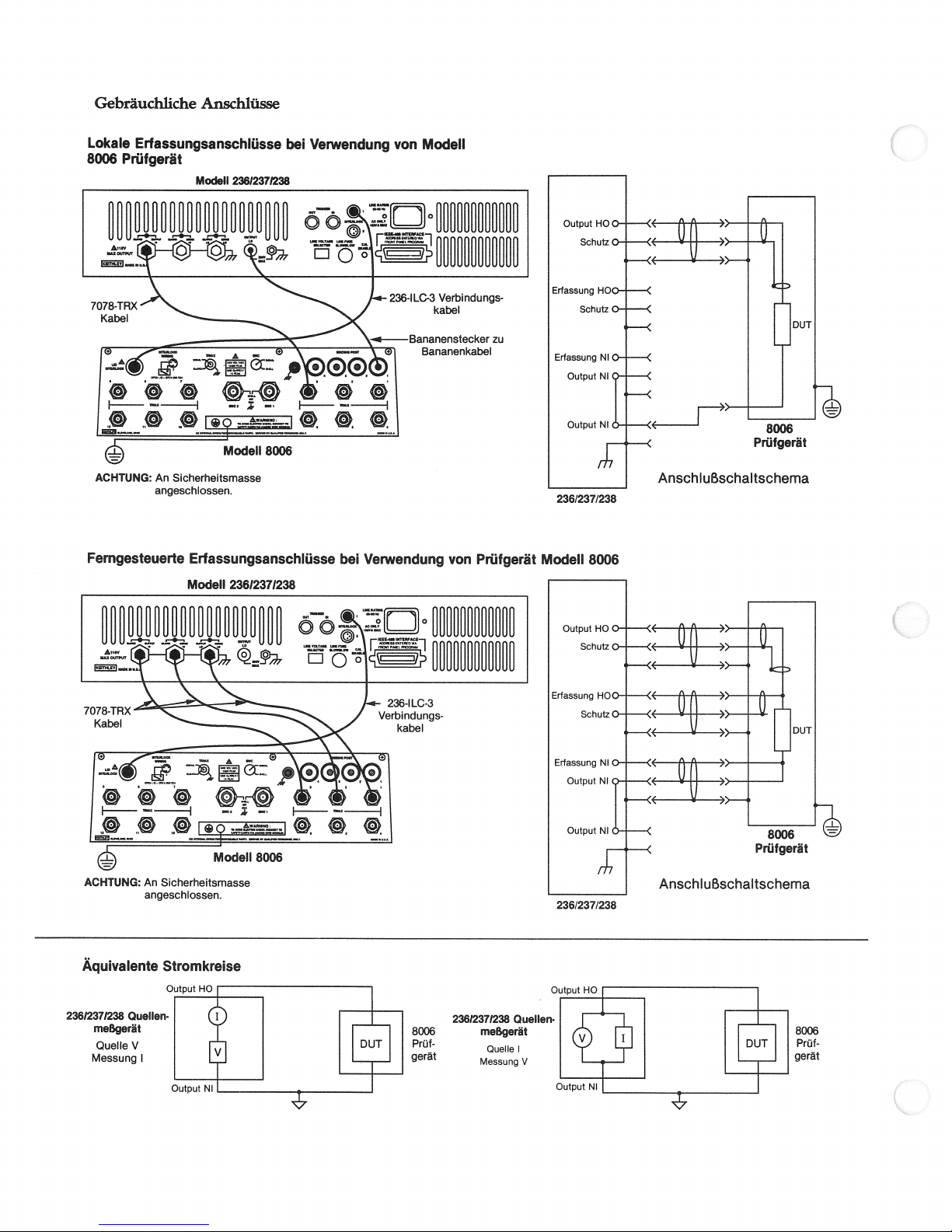
Gebräuchliche
Lokale
Erfassungsanschlüsse
8006
Prüfgerät
ACHTUNG:
An
angesch‘ossen.
Anschlüsse
ModeN
23612371238
Modell
Sicherheitsmasse
8006
bei
Verwendung
von
Modell
236/237/238
Ferngesteuerte
ACHTUNG:
An
angeschlossen.
Äquivalente
Erfassungsanschlüsse
Modell
23612371238
Modell
Sicherhetsmasse
Stromkreise
8006
bei
Vetwendung
von
Prüfgerät
Modell
236/237/238
8006
23612371238
meßgerät
Quelle
Messung
QueNen
V
1
8006
Prüf
gerät
23612371238
meßgerät
Quelle
Messung
QueHen
1
V
8006
Prüf
gerät
Page 13
PRECAUZIONI
osservare
Bisogna
apparecchi
L‘apparecchio
zato
zione
evitare
manuale
delettrocuzione.
di
1‘Istituto
trocuzione
RMS o
tensioni
Prima
tondiprova
Perunmassimo
misura
connettore
completamente
allacciare
chio
sione.
un‘operazione
Non
al
pre
isolate,
Non
sul
manuale
Gli
di
personale
da
sono
e
eventuali
delloperatore
necessario
provaonei
nazionale
allorch
42,4V.
pericolose
delluso
ediponti
di
sorgente,
quando
slacciare
0
dellapparecchio
L‘uso
alcun
toccare
comune
lato
effettuati
capacidisostenere
superare
pannello
posteriore
‘istruzione.
d
strumenti
misura
di
al
procedere
connettori
E
di
lailmentazione
del
privadipericoli.
dcl
conlemani
i
livelli
gli
e
DI
SICUREZZA
le
seguenti
misura
di
sorgente
di
sorgente
precauzioni
quallficatoingrado
corrente
danni
alla
prima
con
Potrebbero
delle
persona.
d‘utilizzare
estrema
esservi
dell‘Apparecchio
americano
vi
buona
prima
necessario
sicurezza,
sono
abitudine
non
dei
liveffi
di
misurare
verificare
accusino
non
l‘apparecchio
II
circuito di
ponti.
cavi
e
di
aUorchIIdispositivo
prova
dispositivo di
ehe
oggetto
potrebbe
circuitoinprova
asciutte
la
tensione
dci
massimi
accessori
e
come
definito
nun vanno
236/237I238
tipo
di
precauzioni
Bisogna
attenzione
delle
regolamenti
massimi
di
sicurezza
un
cheicavi
tracce
toccare
di
prova,
prova
scaricare
e
Bisogna
sicurezza
fomire
alla
o
rimanendo
ehe
segnali
ndr
allacciati
sicurezza
leggere
prima
dovrä
i
rischi
con
sicurezza
di
236/237/238
riconoscere
di
1apparecchio.
quando
letali
tensioni
di
misura
sorgente.
di
(ANSI)
vokaggio
di
attendersi
circuito
sconosciuto.
connessione,
di
di usura,
i
connettori
sotto
tutti
inoltre
massa.
si
incrinature
cavidiprova
i
tensione.
i
condensatori
tenere
in
coperchio
sul
passaggio
un
1
rilevamenti
su
superfici
vuole
misurare.
dell‘apparecchio
prova
dell‘apparecchio,
specifichecduso
sezione
alla
persona.
di
usare
essere
utiliz
delettrocu
necessarie
attenzione
vi
sono
rischi
nell‘apparecchio
Secondo
c‘
superiori
30
a
delet
rischio
cMvisiano
i
condut
avarie.
o
alcun altro
o
Interrompere
prima
ii
chiuso
copen
sotto
garantisce
di
tensione
vanno
asciutte
come
indicato
per
ten
sem
gli
cd
dcl
misura
e
commutatore
la
sele
ENTER.
linea
come
II
valore
fra
II
CONFORMITA (COMPLIANCE):
la
gamma.
Cambiare
rotatorio0sul
GRUPPO
TEMPO
1
zione
DI
(TIME):
attuale
PROTEZIONE
di
soppresso
FILTRO
titativo
base.
leggende
Le
cd
(FILTER):
ffltraggio
di
agendosupulsante
ii
livelloela
II
tasto,
quindi
MISURA
Verifica
(SUPPRESS):
successive
reale
livebo
Indica
in
agendo
premere
ii
periodo
Protegge
dcl
stato
sul
Verifica
gamma
ENTER.
d‘integrazione.
SELECT,
la
conversione
consisteranno
segnale.
dcl
ffltro
pulsante
livello
II
attuali
quindi
nella
di
SELECT,
di
agendo
su
seguente
defferenza
misura.
conformitä
sul
Cambiare
quello
CambiareIIquan
quindisuquello
ENTER.
V
AUTOGAMMA
gamma
GRUPPO
CREARE
dci
virsi
di
premere
parametri
di
MODIFICARE
puntidiscansione
scegliere
della
sorgente
il
valore
per
cambiare
AGGIUNGERE
esistente.
suoi
parametri.
sinne,
quindi
i
dicare
RJCHIAIvIO
misura,
commutatore
indicare
di
prima
(AUTORANGE):
piü
sensibile
DI SCANSIONE
(CREATE):
pulsanti
SELECT
ENTER.
la
tastiera
e
(MODIFY):
II
punto
di
dcl
o
della
sorgente
la
gamma
(APPEND):
Premendo
Servirsi
premere
parametri
elatastiera
(RECALL):
tempo
cd
II
rotatorio
i
parametri.
effetturare
per
Sceglie
Servirsi
per
protetti.
scansione,
ritardo,latastiera
della
l‘APPEND
dci
ENTER.
trascorso
per
Indica
la
scansione.
effettuare
una
per
dcl
cambiarli.
Indica
Servirsi
mutato,
sorgente.
Aggiunge
pulsanti
Servirsi
per
Indica
per
scegliere
soitanto
Permette
scansione
cambiare
commutatore
i
i
pulsanti
agire
vengono
i
parametri
ciascun
all‘apparecchiodiporsi
lii
misura.
enedefinisce
tipodiscansione,
II
della
valori
commutatore
dcl
SELECT
cd
ENTER
puisanti
sui
scansione
una
indicati
SELECT
per
dcl
commutatore
cambiarli.
della
punto
puntoedci
un
i
valori
della
i
parametri.
rotatorio
per
sorgenteedcl
per
scegliere
cambiare
per
SELECT
una
ad
la
scansione
cambiare
ii
rotatorio
sorgente,
scansione.
di
pulsanti
sorgente
sulla
Sen
quindi
indicare
ritardo
dci
rotatorio per
ii
valore
i
valori.
cd
ENTER
scansione
attuale
cd
tipo
di scan-
in-
per
vaiori di
i
dcl
Servirsi
dcl
per
ritardo
SELECT
e
i
Se
i
Ii
simbolo
esservi
Col
telesensore
produrre
causare lesioni
puö
sempre
primadiattivare
tensione.
sione
Per
i
i
modeffi
ti
SOMMARIO
LOCALE
sul modem
una
tensione
attivato,unconduttore
delle
tensioni
i
conduttori
che
ii
Accertarsidiscaricare
esterne.
dispositivi
provaadapparecchi
di
236/237/238
DEI
(LOCAL):
superioreai1000
letaliaOUTPUT
o
morte
telesensore.
in
Avvia
ristabilisceilfunzionamento
GRUPPO
OPERAZIONE
zione
MISURA
della
misura
FUNZIONE
0
a
DELLA SORGENTE
d‘attesa,
DELM
sorgente
la
tensione.
e
(FLTNCT1ON):
scansione.
(OPERATE):
SORGENTE
ne misura
237
staadindicare
danneggiare
e
di
sensore
Non
e/o slacciare
funzione
o
COMANDI
l‘apparecchio
dcl
tasti
a
l‘apparecchio
Mette
(SOURCE
l‘intensitä,
II
Sceglie
ehe
V.
di
sensore
HI
e
GUARD.
i
circuiti
appositamente
siano
sostituire
MAIiconnettori
sempre
multipli,
sarä necessario
fermarli tutti.
in
funzionamento
pannello
anteriore.
MEASURE):
l‘intensitä
o
sceglie
funzionamento
sui
aperto
in
funzione
a
terminali
Tale
esterni.
sorgenti
le
Sceglie
della
corrente
potrebbe
in
grado
tensione
Accertarsi
allacciati
sotto
di
tenere
locale
in
o
tensione
la
sorgente
continua
ten
tut-
posi
SGANCIO
GRUPPO
PREPARAZIONE
dcl
di
ENTER
MANUALE
sta
MANUAL,
ando
GRUPPO
Commutatore
zionamento,
zionediRECALL,
SELEZIONE
zionamento
e
zione
Tastiera:
canceflano
MENU
condizioni
secondi)
e
frequenza
secondi)
DI
commutatore
per
cambiare
(MANUAL):
indicare
ad
comando
estero).
D‘IMMISSIONE
aiterni
dci
dati
Tutti
i
dati
(MENU):
di
ritardo
‚
di
.
Utilizzati
(SETUP):
rotatorio
parimetri.
i
la
necessitä
di sgancio
rotatorio:
regola
Comanda
valori
i
comanda
(SELECT):
nella
e,
di
scansione.
tasti
i
della
numerici.
Viene
funzionamento:
per
default
alimentazione
anche
Verificainstato attuale
per
Ii
lampeggiare
di
indicare
stimolo
uno
sulla
i
parametri,
della
sbarra
DATI
l‘indicazione
sorgente
della
iindicazione
Tali
pulsanti
dci
scelgono
posizionediRECALL,
(eccetto
tastiera
per
ritardo
verificare
della
utilizzato
(avvio/arresto)
‚
(5OHz/6OHz)
effettuare
per
e
auto-prove.
spia
sgancio
di
IEEE-488,
di
di
conformitä
e
dati
II
corrente
‚
sensore
l‘indirizzo
sgancio.
dem
dci tasti
e
di
sgancio
(premere
sgancio
o
parametridifun
van
scansione.
di
i
parametri
comandano
MENU)
cambiare
o
continua
(iocale/a
IEEE-488(0a
Servirsi
SELECT
MANUAL
pulsante
a
nella
e,
di
l‘indica
immettono
seguenti
le
(0
distanza),
com
posi
fun
a
cd
o
65
30
Page 14
Allacdamenti
üpid
Allacciamenti
Modello
re
7O78TRX
H—
8006
‘———H
L@
AflENZIONE
Allacciamenti
Modello
8006
sensore
Modelto
°
allacciare
di
scurezza.
sensore
Modello
locale
23612371238
°
‘
ModeUo
alla
massa
a
distanza
23612371238
utillzzando
»‚
8006
apparecchio
ÖÖ
.ØØ
F—
—
utilizzando
di
ri
intercpendente
Cavo
Cavgna
1
apparecchio
prova
di
prova
23612371238
Schema
degli
allacciamenti
AflENTONE:
Circuiti
AppareccNo
defla
sorgente
Sorgente
Misura
aflacciare
di
equivalenti
misura
di
23612371238
V.
1
sicurezza.
afla
massa
Apparecchio
di
misura
sorgente
23612371238
Sorgente
Misura
della
V
1.
23612371238
Schema
degli
allacciamenti
Apparecchio
1
di
prova
8006
Page 15
‘H
ALl
{
11
!1
Li
JJ
%
s
i
L
pz
+
i;
r
)C/D
v
Tj
;1c;
L*
g4
j
+J
i
-‘
<z
‚N.E
\j
‚
N/)r
N
‘,\
-
L
‚
:
r
-:
‘-J
\
Nt
\-
-
-j
N
:
O\
-D
—
N
$
-\J
\
\
.‘-
j
‚
\
N
>
t
\
\
«
J
-\J
-)
J
+
J
‘<,
=
<4
s
\-
6
:‘
N
4
-‘
.
‘
4
4*64*
-
.
‚
N
-‚
\
4
N
‚U:frL
\N
1GG-
(
‚
J-
\
J
0
‚6
a<
i
N
;
NS
‚L
m
N
:
-j
-
‘
J
jL
46
\-
*1:;:;
lJ4+
*u)
‚;
Zt
U
A4+6
1%::pE\/
i
-Eu
->
L)
‚
HL
h
$
‚
-;
\
L}t
g
•_)
-
s
‚
1-
ApE
jn
-
-+
.-(
‘
-
4‘
--
IJj
L
ia‘i)
—-)
‚4G
--
4J
1J
J
N
N
r<JIk
_)
r<
r
-
)
<
*
J
‚
-
&
J
/
\
-
r
--
z
-‚-
-
4
Q
z
}
N
.
->-
__)
6\
--
:
-.
N
>
-
.
<--
\J
4.
-
)
\J
rjj>
I4
zI
K
AJ•‘
J
N
4j
‘
J
J
T
L
N
..
‚
-
:
‚—
J
\
\
.
4
--j
J
‘-
.
1
-\
4
-J
k)*
‚6
4
.LL
\7
_J
-\
«
6
-
\
4
)
<\
i
--
*
\\
N
‚
s
N
/
!
.
:
u
“
n
‘,\
IH
‘
-J
N
-%‚
Q
1
JD
0
.:
—
R
N
-
(J-
_j
‘,\
z
r‘
j
6
—
0
‚
-)
‘
j_
‚
4
:;
i
L1L
N
b
‚
;
k
-
4
4
*
4
‚
\J
\
(b
;
)
*6
—)
L
‚\
÷
kU
J
—
£<
N
N
N
0
N
j
.
<
a
6
-R
-
Z
6c)
-L
*6
-
0
:\
n
jj-
N
-6
N:
-4i
r1
\
f6
-
\
*
/
c
s
ZN
‚\
j
I
±
I
‚k
‚\A
r
1-
+6
d
‚
%
N
Page 16
0)
dl
CO
9‘
>.4
-7-
:11111
l}
rH
9
t1
>.4
3
0
a
99
0-0
CD
Co
a
0
cD
99
111
CD
0,
.—
0
—
-
‘-4
Ok
H
>.4
9‘
>
;jw
rH
lj
(J
Co
dl
dl
oo(
3
-.3
(‚3
0)
3
$
41
2
99
H1
g)
o
99
co
OCf)
c
cD
00
99
111
0
c
0
v
19
H
_-4—1
‘-4
H
Co
7_
1
<
>J
4
ii
w—
<>
—
r%)
0)
(‚3
0
>1
flll
>
Page 17
MEDIDAS
Es
necesario
medidores
El
medidor
nal
experimentado
conocedor
y
lidad
dc
antes de
Tener
sumo cuidado
mortal
voltaje
fuente.
dor
de
(ANSI)
de
voltaje
medidadeseguridad
cualquier
Inspeccionar
puente
Para
mäxima
DE
SEGURIDAD
tomar
las
de
fuente
modelo
medidasdeseguridad
modelos
236/237/238
capazdereconocer
de
las
lesiones.
este
instrumento.
medidas
Leer
sufrir
usar
cuando
presente
en
El
establece
en
Instituto
que
son
circuito
busca
existe peligro
superioresa30VRMSode
es
anticiparla
desconocido
los
cablesdeconexiön,
de
posible
seguridad,
no tocar
de
cablesdepruebaocualquier
aplica
corriente
conectar
probador
La
operaciön
No
tocar
lado
comün
el&trica.
superficie
una
corriente
el&tricaalcircuito
el&tricaydescargar
cablesocables
puente.
mientrasseaplica
segura
requiere
ningün
objeto
dcl
Siempre
que
circuito
sometidoapruebaotierra
tomar
las
secayaislada
do
exceder
los
No
cl
panel
en
operaciön
No
se
El
simbolo
nales
puede
Coneidetector
darä
por
SALIDA
puede
je
teriores
bien
conectados
biar
las
asegurar
energla
Para
los
deberä
desenergizados,
todos
RESUMEN
LOCAL
ciones
GRUPO
OPERAR
niveles
mäximos
traseroycomo
dcl
manual
dc
instrucciones.
deben
conectar
haber
resultado
los
que
apareceencl
presente
remoto
la
apariciön de
instrumentos
habilitado,
ALTAyde GUARDA (OUTPUT
causar
lesioneseindusolamuerte,
Siempre
asegurar
antesdehabffitareidetector
conexiones
de
descargar
estando
y/o
externas.
sistemasdcprueba
manteneryasea
(LOCAL):
dcl
panel
todos
DE
LOS
Poneeiinstrumentoenlocalyrestablece
frontal.
DELAFUENTE
(OPERATE):
Pone
reserva.
MEDIDA
dc
FUENTE
(SOURCE
fuenteycorriente dc
medida.
FUNCION
(FUNCTION):
antesdeusar
los
236/237/238.
ser
usado
estä
diseüado
los
peligros
manual
peigro
requeridas para
del
de electrochoque.
de seguridad
el
exista
los
enchufes conectores
Normalizaciones
de electrochoque
crestadc42,4V.
presencia de
antesdetomar
conductores
desgaste,
otro
los
Tambin,
los
conector de
que
capacitores
grietasoroturas
conectores
estä
se
mantener
corrientealdispositivo
cl
usodcun
pudiera
enclavamiento dc
proporcionar
para
de
operador
del
Nacional
voltajes
mediciones
de
del
medidor, probador,
instrumento
probando.
antesdeconectarodes-
que
un
paso dc corriente
por
los
electrochoques
evitarlaposibi
cuidadosamente
Podria
probador
Norteamericano
cuando
los
Una
peliosos
pruebaycables
antes dc
mientras
Cortar
cerradalatapa
estä
se
probando.
lii
dcl cabledcenergla
con
las
manos
secas
mediciones
capazdcresistirclvoltaje
dc
seüal
dcl
y
modelo
instrumento,
las
especificaciones
accesorios
237
indica
se
define en
que
se
como
a seres
queenlos
dc
estä
secciön
y
humanos.
1000Vomäs.
conductordcdetecciön
un
voltajes
mortales
HI
que
los
conductores
la
energla
e1ctrica
desconectar la
interconectadosdcmedidores
los
modelos
236/237/238
y
dafiar
y
remoto.
fuentes
enlaconexiön
GUARD).
los
de
detecciön
NUNCA
aplicada
suministro
dc
energizados,
Este
circuitos
mültiples,
CONTROLES
unidadenestadodcfuncionamientoodc
la
MEASURE):
medida,
Sclecciona
corriente
o
operaciön
Selecciona
dc
cc
fuenteytensiön
dc
o
tensiön
barrido.
primaria
aparatos
perso
haber
medi
o
niveles
buena
cada
toda
tapa.
pie
sobre
midien
indica
se
termi
abierto
volta
estn
Siempre
las
opera
uso.
cam
en
dcl
dc
ex-
DOCILIDAD
medida.
dc
0
tecladoyluego
GRUPO
TIEMPO
en
curso
ENTER
SUPRIMIR
ciöndclfneadcbase.
cl
valor
FILTRO
tidaddcifitraciön
AUTOGAMA
margen mäs
GRUPO
CREAR
los
botones
se
la
ENTER.
cl
teclado
y
MODIHCAR
los
puntos
cl
punto
dc
rctardo,
al
valordcfuente
cl
margen dclafuente
AGREGAR
pulsar APPEND
botones
TER.
teclado
LLAMAR
mediciön
rilla
giratoria
parämetros.
dc
ejecutarse
GRUPO DE
dc
PREPARACION
rador.
SELECT
MANUAL
ca
quc
dc
se
o
comando
parador
GRUPO
Perilla
operaciön,
modo
SELECCIONAR
racionales
sualizaciöndclos
Teclado:
(registrar)
o
dc
MENU
operaciön:
dc
defecto
(ines
ejccutar
(COMPLIANCE):
nivelymargenencurso
Cambiar
DE
(TIME):
pulsando
ei
pulsar
MEDICION
Verifica
los
ENTER.
elperiododcintegraciön.
botones
(ENTRAR).
(SUPPRESS):
suprimido
(FILTER):
Guarda
Las
lecturas subsiguientes
cl
nivel
y
realdcla
Indicaclestado
pulsando
los
(AUTORANGE):
sensible
para
tomar una
DE
BARRIDO
(CREATE):
Usarlaperilla
dc
dc barrido,
SELECT
Usarlaperilla
para
(RECALL):
y
Seleccionaunbarrido
SELECT
para
para
cambiarlos.
(MODIF):
barrido
registradosenla
los
cl
tccladoyla
cambiö,
(APPEND):
visualizaclbarrido
se
para
giratoria
cambiarlos.
Visualiza
tiempo
elegir
para
Visualiza
barrido.
cl
transcurrido
los
cl
cambiareitipo dc
giratoria
Visualiza
botones
tecla
usar
los
dc
energta.
Aüadeunbarrido
cambiarcltipodcbarrido
para
elpunto
valores
DISPARADORES
Usarlaperilla
(SETUP):
ENTER
y
(MANUAL): La
requiereunimpulsodcdisparo
se
disparo
dc
entrada
dc
DE ENTRADA
giratorja:
Controlalavisualizaciöndclos
ajusta
RECALL,
controla
(SELECT):
alternativos
Verfficalacondiciönoestado
giratoria
cambiar
para
luz destellante
sobrelabarra
exterior).
DE
los
valores
dc fuenteydc
la
visualizaciöndclos
Estos
cuando
y,
datosdcbarrido.
botones
Se
datos
usa
dcl teclado
numeticos.
para
verfficarocambiar
cc(0a
Todos
los
anular
0
(MF.NU):
retardo
(activado/desactivado)
Hz),ydirecciön
Hz/60
(50
autopruebas.
Verificaclniveldcdocilidadyei
conlaayuda
Cambiar
SELECT
la
conversiön
(SELECCIONAR)yluego
siguiente
como
seränladiferencia
seflal.
dcl
filtrodcmediciön.
SELECTyluego
botones
Permitealaparato
Cambiar
ENTER.
pasarala
medida.
define
sus
parämetros.
en
seguida pulsar
y
parämetros
los
retardoydc
dc
Usarlaperilla
elegirclvalor
cambiar
los
barridoyaexistente.
parämetros.
seguida
en
y
parämetros
dc barridoycl
dclafuente,
dc barrido.
para
retardo
solamente
para
los
SELECT
ENTER
botones
visualizar
los
parämetros
para
ylos
dc
y
barrido
visualizar
valores
memoria.
para
para
SELECTyENTER
a
un
en cursoysus
los
cada
punto
SELECT
botones
fuenteydc
actual dcl
para
visualizar
los
parämetros.
colectora
los
dcl
disparador
(pulsaciön
o
bus
parämetros,
MANUAL
dcl
botön
IEEE-488,oun
DATOS
distintos
parämetros
docilidad,ycuando
datos
dc barrido.
botones
estäenmodo
segundos)
65
detecciön
‚
IEEE-488
seleccionan
(excepto
‚
(local/remota)
(0a30).
RECALL,
MENU)
las
retardo
los
parämetros
controlan
sirven
siguientes
predetermmnado
frecuencia
‚
Tambin
margen
dclaperilla
la
selecciön
una
mcdi-
entre
la
can
gama
Usar
dc barrido
fuente
dc
para
elegir
dc fuente
valores.Sicl
cambiar
para
Usar
los
EN
pulsar
los
valores
dc
Usarlape
visualizar
los
antes
dispa
las
tcclas
mdi-
MANUAL,
dis
dc
estä
en
ope
vi-
la
para
entrar
condiciones
per
dc
usa
para
se
o
o
Al
Page 18
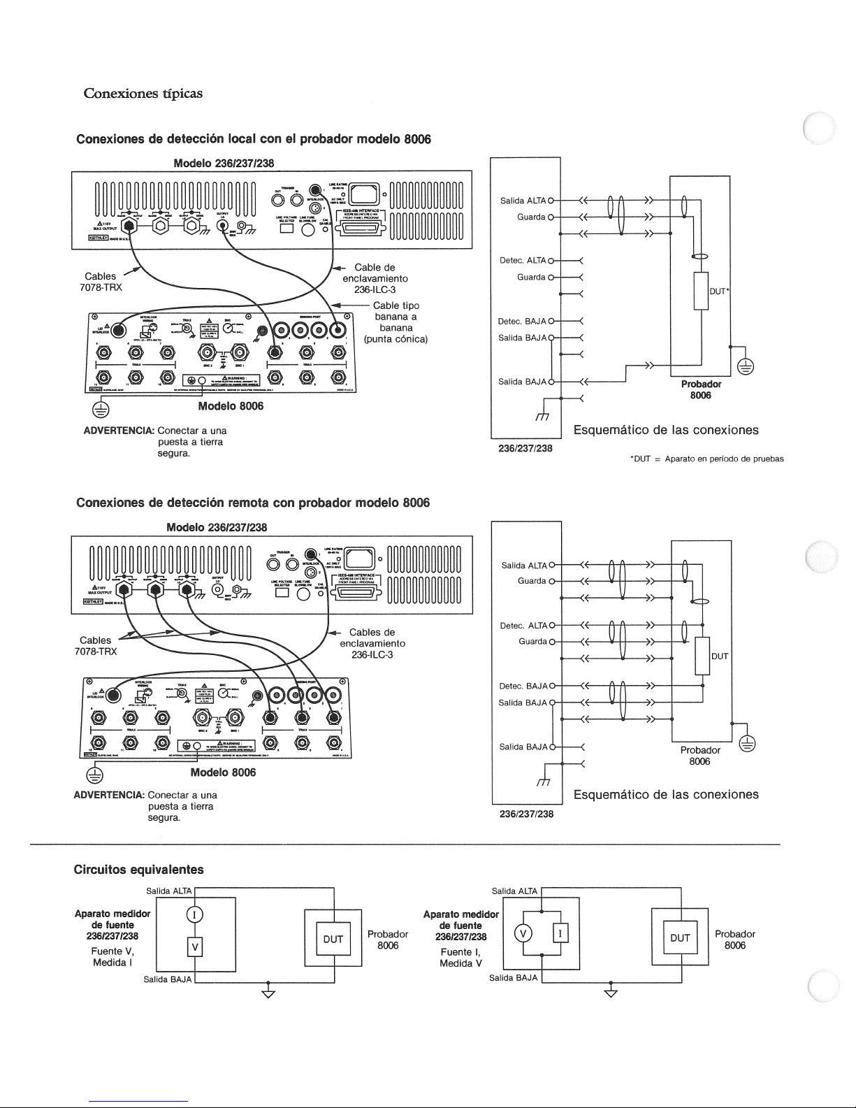
Conexiones
Conexiones
1
ffpicas
detecciön
de
Modelo
23612371238
Mod&o
local
8006
con
ei
probador
modeio
8006
Probador
8006
ADVERTENCA:
Conexiones de
ADVERTENCA:
Conectar
puesta
a
segura.
detecciön
Modeio
Modelo
Conectar
puestaatierra
segura.
a
una
a
flerra
remota con
23612371238
8006
una
probador
modeio
8006
236/237/238
236/237/238
Esquemätico
*DUT
de las
=
conexiones
Aparatoenperiodo
de
pruebas
Circuitos
Aparato
23612371238
fuente
de
Fuente
Medida
equivalentes
Satida
medidor
V,
Probador
8006
fuente
de
23612371238
Fuente
1,
Medida
V
Probador
8006
Page 19
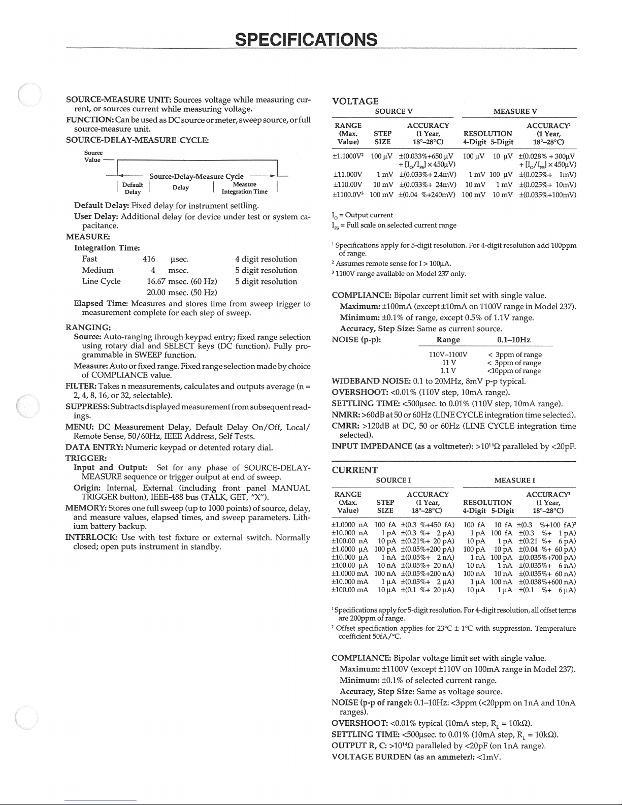
SPECI
FICATIONS
SOURCEMEASURE
or
sources
rent,
FUNCTION:
source-measure
Can
current
be
used
unit.
UNIT:
SOURCEDELAY-MEASURE
Source
SourceDe1ayMeasure
Default
Delay
Default
User
Delay:
Delay:
Fixed
Additional
delay
pacitance.
MEASURE:
Integration
Fast
Medium
Line
Elapsed
measurement
Cycle
Time:
Time:
416
4
16,67
20.00
Measures
complete
RANGING:
Auto-ranging
Source:
using
grammable
Measure:
of
COMPLIANCE
FILTER:
2,
4,8,16,or32,
SUPPRESS:
ings.
MENU:
Remote
DATA
ENTRY:
rotary
Auto
Takes
Subtracts
Measurement
DC
Sense,
n
through
dial
and
in
SWEEP
or
fixed
value.
measurements,
selectable).
displayed
50/60Hz,
Numeric
TRIGGER:
Input
and
Internal,
measure
battery
open puts
Output:
sequenceortrigger
External
button),
Stores
one
full
values,
backup.
with
Use
instrumentinstandby.
IEEE-488
elapsed
MEASURE
Origin:
TRIGGER
MEMORY:
and
ium
INTERLOCK:
closed;
Sources
while
as
DC
voltage
measuring
sourceormeter,sweep
CYCLE:
Delay
for
instrument
delay
for
device
isec.
msec.
msec.
msec.
and
for
(60
(50
stores
each
stepofsweep.
Hz)
Hz)
keypad
SELET
function.
range.
Fixed
keys
range
caiculates
measurement
Delay,
Address,
for
any
(including
bus
times,
Default
detented
or
phaseofSOURCE-DELAY
output
(TALK,
and
IEEE
keypad
Set
sweep (upto1000
test fixture or
while
vo1tage
Cycle
Measure
J
Inteation
settling.
test
under
digit
4
digit
5
digit
5
time
from
entry;
fixed
(DC
function).
selection
and
outputs
from
Delay
Seif
Tests.
rotary
of
at end
front
panel
GET,
points)
sweep parameters.
external
switch.
measuring
source,
L
Time
or system
resolution
resolution
resolution
sweep trigger
selection
range
Fully
madebychoice
average
subsequent
On/Off,
“X“).
ofsource,
Local/
dial.
sweep.
MANUAL
delay,
Normally
or
read
cur
pro-
(n
Lith
full
ca
to
=
VOLTAGE
SOURCE
RANGE
(Max.
Value)
±1.1000W
±11.000V
±110.00V10mV
±1100.0V3100
10
=
‘n
1
Specifications
of
2
Assumes
3
1100V
COMPLIANCE:
Maximum:
Minimum:
Accuracy,
NOISE
WIDEBAND
OVERSHOOT:
SETTLING
NMRR:
CMRR:
selected).
INPUT
CURRENT
RANGE
(Max.
Value)
±10000
±10.000
±10000
±1.0000tA100
±10000
±10000
±1.0000mA100
±10.000
±10000
STEP
SIZE
100
1
Output
current
Fiill
range.
on selected
scale
apply
remote
range
availableonModel
Step
(p-p):
TIME:
>60dB
>120dBatDC,50or
IMPEDANCE
SOURCE
STEP
SIZE
nA
100fA±(0.3
nA
nA
10
iA
tA
10
mA1iA
mA
10
V
ACCURACY
(1
18°-28°C)
iV
±(O033%+650
+
[Io/IF]
mV
±(O033%+
±(O.033%+
mV
±(O04
%+24OmV)
current
for 5-digit
seine
for
1>1OOtA.
Bipolar
current
±lOOmA
±0.1%
NOISE:
Size:
<0.01%
at5O
(except ±lOmA
of
range,
Same
0.1
(110V
<500j.tsec.
or
60Hz
(asavoltmeter):
1
ACCURACY
(1
18°—28°C)
1
pA
pA
pA
1nA±(0.05%÷
nA
nA
tA
%+450
%+
±(0.3
±(0.21%+
±(0.05%+200
±(0.05%+
±(0.05%+200
±(0.05%+
%+
±(0.1
Year,
tV
X
450jtV)
2.4mV)
24mV)
range
resolution.
only.
237
limit
except
as
current
Range
110v—1100v
11
1.1
V
20MHz,
to
step,
0.01%
to
(LINE
60Hz
Year,
fA)
pA)
2
20
pA)
pA)
2
nA)
20
nA)
nA)
A)
2
jiA)
20
MEASURE
RESOLUTION
4-Digit
5-Digit
1
10
For
set
on
0.5%
tV
mV
mV
mV
1100V
10
100
10
4-digit
with
1.1V
of
jiV
iV
1
mV
mV
resolution
single
range
range.
100
100
source.
0,1—10Hz
<
V
lOmA
CYCLE
(LINE
RESOLUTION
4-Digit
100fA10fA±(0.3
100pA10pA±(0.04
100
3ppm
<
3ppmofrange
<loppm
8mV
(110V
p-p
range).
step,
typical.
lOmA
integration
CYCLE
>10142
paralleled
MEASURE
5-Digit
1pA100
10
1nA100pA±(0035%+700
10
fA
pA1pA
nA1nA
nA10nA
1iA100
10
nA
iA
1
jiA
V
ACCURAC
Year,
(1
18°-28°C)
[1o/IFSI
300jiV
+
X
45OtV)
lOmV)
lmV)
±(O.028%
+
±(O.025%÷
±(O.025%+
±(O035%+lOOmV)
add
lOOppm
value.
in
Model
237).
of
range
of
range
range).
time
selected).
integration
ACCURACY‘
±(0.3
±(021
±(0.035%+
±(0.035%+
±(0.038%+600
±(0.1
time
<2OpF.
by
1
Year,
(1
18°—28°C)
%+100
%+
1
%+
6
%+
60
6
60
6
%+
fA)
2
pA)
pA)
pA)
pA)
nA)
nA)
nA)
iA)
1
Spedfications
200ppm
arc
2
Offset
specification
coefficient
COMPLIANCE:
5OfA/°C.
Maximum:
Minimum:
Accuracy,
NOISE
(p-p
ranges).
OVERSHOOT:
SETTLING
OUTPUT
R,
VOLTAGE
applyfor
5-digit
of
range.
applies
Bipolar
±1100V
(except
±0.1%ofselected
Step
Size: Same
of
range):
0.1—10Hz:
<0.01%
typical
TIME:
<500jisec.
>10142
C:
BURDEN
paralleled by
(as
resolution.
for
23°C±1°C
voltage
±110V
as
an
ammeter):
current
voltage
(lOmA
to
For4-digit
limit
on
<3ppm
0.01%
<2OpF
resolution,
with suppression.
with
lOOmA
range.
single
rangeinModel
set
source.
(<20ppm
RL
(on
=
step,
inA
lOk2).
step,
(lOmA
<lmV.
on
R
range).
all
offset
Temperature
value.
inA
and
=
lOk2).
terms
237).
lOnA
Page 20
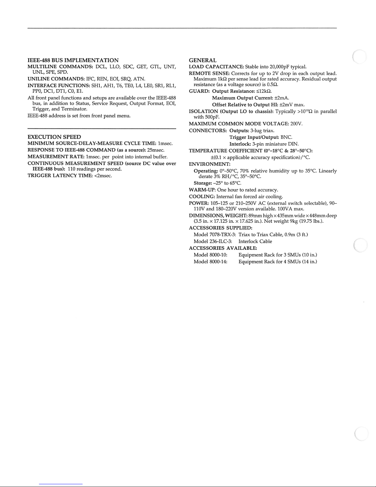
SPE,
DC1,
front
BUS
IMPLEMENTATION
COMMANDS:
SPD.
COMMANDS:
FUNCTIONS:
DT1,
CO,
panel
functions
and
Terminator.
addressisset
SPEED
SOURCE-DELAY-MEASURE
TO
IEEE-488
RATE:
MEASUREMENT
110
bus):
LATENCY
IEEE-488
MULTILINE
UNL,
UNILINE
INTERFACE
PPo,
All
bus,inadditiontoStatus,
Trigger,
1EEE488
EXECUTION
MINIMUM
RESPONSE
MEASUREMENT
CONTINUOUS
IEEE.488
TRIGGER
IFC,
El.
and
from
COMMAND
lmsec.
readings
TIME:
DCL,
REN,
SHI,
setups
Service
front
per
<2msec.
LLO, SDC,
EOI,
AHI,
are
Request,
panel
per
point
SPEED
second.
SRQ
T6,
TEO,
available
menu.
CYCLE
a
(as
source):
into
(source
GET,
ATN.
L4,
over
Output
internal
GTL,
LEO,
the
Format,
TIME:
25msec.
DC
UNT,
SRI, RLI,
IEE&488
lmsec.
buffer.
value
EOI,
over
GENERAL
LOAD
CAPACITANCE:
REMOTE
Maximum
resistance
GUARD:
ISOLATION
with
MAXIMUM
CONNECTORS:
TEMPERATURE COEFFICIENT
ENVIRONMENT:
Operating:
Storage:
WARM-UP:
COOLING:
POWER:
110V
DIMENSIONS,
(3.5
ACCESSORIES
Model
Model
ACCESSORIES
Model
Model
SENSE:
lk2
a
(as
Output
Maximum
Offset
(Output
500pF.
COMMON
x
±(0.l
derate
0°—50°C,
RH/°C,
3%
—25°
to
One
Internal
105—125or210—250V
and
180—220V
in.x17.125
WEIGHT:
SUPPLIED:
7078-TRX-3:
236-ILC-3:
AVAILABLE:
8000-10:
8000-14:
Stable
Corrects
per
sense
source)
Output
LO
MODE
70%
35°—50°C.
fan
forced
version
x
17.625
Triax
Interlock
Equipment
Equipment
lead
to
to
Input/Output:
89mm
voltage
Resistance:
Relative
Outputs:
Trigger
Interlock:
applicable
65°C.
hourtorated
in.
forupto
Output
3-lug
3-pin
accuracy
relative
in.).
to
into
rated
for
is
O.52.
l2k2.
Current:
chassis):
VOLTAGE:
triax.
miniature
(O°-18°C
accuracy.
cooling.
air
AC
(external
available.
high
Net
Triax
Cable
Rack
Rack
20,000pF
2V
HI: ±2mV
specification)/°C.
humidity
Cable,
typical.
drop
in
accuracy.
±2mA.
max.
Typically
200V.
BNC.
DIN.
&
28°-50°C):
up
switch
100VA
max.
x435mmwide
weight
9kg
0.9m
for3SMUs
for
4
SMUs
each
Residual
>10b02
to
35°C.
selectable),
x448mm
(19.75
(3
ft.)
(10
(14
output
in
lbs.).
in.)
in.)
lead.
output
parallel
Linearly
90—
deep
Page 21
Table
Contents
of
SECTION
1.1
1.2
1.3
1.4
1.5
1.5.1
1.5.2
1.5.3
1.5.4
1.5.5
1.5.6
1.5.7
1.5.8
1.5.9 lOOmA
SECTION
2.1
2.2
2.3
2.4
2.5
2.6
2.6.1
2.6.2
2.6.3
2.6.4
2.7
2.8
1
INTRODUCTION
ENVIRONMENTAL
INITIAL
REQUIRED
VERIFICATIONS
Equipment
Common
Voltage
Voltage
Remote
Low
Current
Low
Current
lOOmA
2
=
INTRODUCTION
RECOMMENDED
ENVIRONMENTAL
WARM-UP
LOCK
CAL
CALIBRATION
Equipment
Voltage
lOOmA
Low
CALIBRATION
CALIBRATION
Performance
COND1TIONS
EQUTPMENT
TEST
PROCEDURES
Characterization
Mode
Source
Measure
Sense
Measure
Source
Verification
Verification
(inA
(inAtolOmA)
Range
Calibration
PERIOD
PROCEDURES
Characterization
Calibration
Range
Current
Calibration
Ranges
ERRORS
PROGRAM
Verification
CONDITIONS
Verification
Verification
lOmA)
to
Verification
Range
Verification
CALIBRATION
CONDITIONS
Calibration
Measure
Source
EQUIPMENT
(inA
Ranges
Ranges
—
lOmA)
Verification
Verification
1-1
14
14
1-1
1-1
1-3
1-6
1-8
1-9
141
1-12
1-15
1-18
1-20
2-1
2-1
2-2
2-2
2-2
2-2
2-3
2-6
2-9
2-11
2-13
246
SECTION
3.1
3.2
3,3
3.4
3.5
3.6
3.7
3.8
3.8.1
INTRODUCTION
LINE
FAN
BATrERY
HANDLING AND
DISASSEMBLY
SPECIAL
TROUBLESHOOTJNG
Maintenance
3
—
REPLACEMENT
FUSE
FILTER
Recommended
CLEANING
REPLACEMENT
HANDLING
CLEANING
INSTRUCTIONS
OF
Test
Equipment
PRECAUTIONS
STATIC
SENSITIVE
DEVICES
3-1
3-1
3-1
3-2
3-4
3-4
3-11
3-11
3-11
Page 22
382
38.3
3.8Ä
3.8.5
3.86
Diagnostics
Power
Analog Control
Analog
Digital
Supply
Switching
and
Display
Checks
Lines
Checks
341
343
344
344
3-16
SECTION
4.1
4.2
4.2.1
4.2.2
42.3
4.2.4
4.3
4.4
44.1
4.42
44.3
4.4A
4.5
INTRODUCTION
ANALOG
A/D
DIGITAL
POWER
SECTION
51
5.2
5,3
5,4
5,5
INTRODUCTION
PARTS
ORDERING
FATORY
SCHEMATIC
4
=
Principles
CIRCUITRY
V/I
Control
Output
Feedback
V/I
Resonant
CONVERTER
I/O
Controller
Source/Measure
Communications
Display
5
LISTS
and
Stage
Converter
CIRCUTTRY
Circuitry
SUPPLY
Replaceable
INFORMATION
SERVICE
DIAGRAMS
of
Operation
Readback
(Model
Controller
Parts
237)
AND
COMPONENT
LOCATION
DRAWINGS
4-1
4-2
4-2
4-4
4-6
4-8
4-8
4-9
4-9
4-10
4-10
4-10
4-11
5-1
5-1
5-1
5-1
5-1
Page 23
List
of
Illustrations
SECTION
Figure
Figure
Figure
Figure
Figure
Figure
Figure
Figure
Figure
14
1-2
1-3
1-4
1-5
1-6
1-7
1-8
1-9
SECTION
Figure
Figure
Figure
Figure
Figure
Figure
Figure
2-1
2-2
2-3
2-4
2-5
2-6
2-7
1
Performance
Setup
Setup
Setup
Setup
Setup
Setup
Setup
Setup
Setup
2
Calibration
Calibration
Setup
Setup
Setup
Current
Ui
U7
Verification
for
Equipment Characterization
for
Common
for
Voltage
for
Voltage
for
Remote
for
Low
for
Low
for
lOOmA
for
lOOmA
Switch
for
Equipment Characterization
for Volts
for
lOOmA
Ranges
Error
Status
Calibration
Mode
Source
Measure
Sense
Current
Current
Measure
Source
(Cal
Calibration
Range
Calibration
Word
Status
Verification
Ranges
Verification
Measure
Source
Range Verification
Lock)
Calibration
Word
Verification
Ranges Verification
Ranges Verification
Ranges
Range
Verification
(lnAtolOmA)
Verification
(lnA
(lnA
to
to
lOmA)
lOmA)
1-4
1-7
1-9
1-10
1-12
1-13
1-16
1-19
1-21
2-2
2-4
2-7
2-10
2-12
2-15
2-16
SECTION
Figure
Figure
Figure
Figure
Figure
Figure
3-1
3-2
3-3
3-4
3-5
3-6
SECTION
Figure
Figure
Figure
Figure
Figure
Figure
Figure
4-1
4-2
4-3
4-4
4-5
4-6
4-7
3—Maintenance
Line
Digital
Resonant
Output
Analog
Model
4
=
Overall
Simplified
Model
Model
Simplified
Damping
Simplified
Voltage
Principles
Switch
Board
Converter
Board
Board
(Shields
237
Exploded
Block
Diagram
Schematic
236
Output
237
Output
Schematic
Relay
SchematicofResonant
and
Line
Fuse
Board
(Model
Removed)
View
of
Operation
of
V/I
Stage (Simplified Schematic
(Simplified Schematic
Stage
of
V/I
Contact
Bounce
237)
Control
Feedback
Converter
and
Readback
Diagram)
Diagram)
3-1
3-3
3-5
3-6
3-7
3-9
4-1
4-3
4-5
4-5
4-6
4-7
4-9
Page 24

Page 25
List
Tables
of
SECTION
Table
1-1
Table
12
Table
1-3
Table
1-4
Table
1-5
Table
1-6
Table
1-7
Table
1-8
Table
1-9
SECTION
Table
2-1
Table
2-2
Table
2-3
Table
2-4
SECTION
Table
3-1
Table
3-2
Table
3-3
Table
3-4
Table
3-5
Table
3-6
Table
3-7
Table
3-8
Table
3-9
Table
3-10
1
Performance
Required
Specifications
Model
Voltage
Voltage
Allowable
Low
Allowable
Low
2
Calibration
Required
Specifications
Model
Calibration
Maintenance
3
=
Line
Recommended
Power
Analog
Analog
Analog
Analog
Analog
Digital
Display
Verification
Equipment
Test
For
Alternate
I-Source
263
Source Verification
Measure
Current
Current
Test
263
Fuse
Selection
Supply
Switching;
Switching;
Switching;
Switching; Sensing
Switching;
Circuitry
Circuitry
Verification
Reading
Measure
Reading
Source
Equipment
For
Alternate
I-Source
Error
Messages
Troubleshooting
Checks
Checks
Checks
Equipment
Characteristics
Caiculations
Verification
Caiculations
Verification
Equipment
Characterization
Current
Volts
Feedback
A/D
Ranging
Ranging
Multiplexing
for
Low
(inA
for
Low
(inA
to
Equipment
Current
to
lOmA)
Current
lOmA)
Measure
Source Verification
Verification
(lmA
(lmA
to
to
lOmA)
lOmA)
12
1-3
1-5
1-8
1-11
1-13
1-14
....
1-15
1-17
2-1
2-2
2-5
2-14
3-1
3-11
3-13
3-14
3-15
3-15
3-15
3-16
3-17
3-18
4
SECTION
Table
4-1
=
Principles
Volts
Range
of
Relays
Operation
4-8
Page 26

Page 27
SECTION
Performance
1
. .
Verification
1
1
INTRODUCTION
The
procedures
verify
that
the
stated
Performance
strument
misadjustment
tion
instrument
Before
sure
the
tor‘s
1
All
and
1
in the
is
may
also
accuracy,
If
the
instrument
than
1
performance
contact
factorytodetermine
tion.
attempting
you
are
Model
236/237.
Manual
.2
ENVIRONMENTAL
measurements
less
than
at
INITIAL
3
The
Source
3wire
outlined
instrument
specifications
verification
first received
has
occurred
be
performed
orfollowing
year
from the
falls
your
Keithley
anyofthe following
familiar
for
with
Refertothe
complete
shouldbemadeat18-28°C
70%
humidity.
CONDITIONS
WARNING
Measure
power
cord
in
this
section
is
operating within
at
the front
maybeperformed
ensure
to
whenever
NOTE
is stffl
date
outside
the
during
under
representative
calibration,
shipment),
of
the
specified
correct
that
shipment.
thereisquestion
warranty
course
procedures,
the
controls
and
Model 236/237
information.
CONDITIONS
Unitisequippedwith
that
contains
maybeused
the
of
this
no
when
damage
Verifica
if
desired.
(less
and
manual.
the
its
range,
the
or
of
ac
operation
Opera
(6582°F)
a
separate
a
limits
in
make
to
or
of
of
grotmdwire and
grounded
are
made,
power
outlet
electric
Model
The
up
warm
procedures.Ifthe
cation
extremesoftemperature
paragraph
temperatures
ternal
ture.
Typically,
unit
range.
1.4
Table
verification
used
tions
equipment
quired
Table
The
are
do
measurement
is 10°C
that
RECOMMENDED
1-1
longasthe substitute
as
least
at
ifusing
1-2.
accuracy
based
include
not
caiculate
specifications
then
tions,
outlets,
instrument
ground.
line
may
result
shock,
236/237
foratleast
additional
1.2),
it takes
(18°F)
summarizes
procedures.
as
good
characterization
equipment
limits
on
test
falls
limits
and
repeat
Model236/237
the
only
new
must
one
to
as
stated
equipment
slightly
based
test
is
designedtobe
When
proper
chassis
Failuretouseagrounded
in injury
turned
be
hour
before
instrument
(outside
tinte
should
reach
normal
one
additional
outside
the
TEST
recommended
Alternate
connections
is
connected
or
death
on
beginning
has
the
range
be
operating
hourtostabilize
specified
EQUIPMENT
equipment
equipment
equipment
in
those
that
listed
(paragraph
the
in
Table
the
meets
verification
specifications,
tolerance.
outside
both
equipment
the
on
instrument
accuracy
test.
used
with
to
due
to
and
aliowed
verifi
the
been
subject
specified in
allowed
for
tempera
temperature
for
may
has
specifica
Note
1-2.
1.5.1)
is
not
specifications
procedures
and
particular
If
a
allowed
range,
accuracy
specifica
to
to
in-
a
the
be
that
re
in
they
14
Page 28
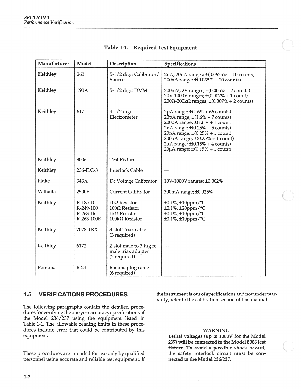
SECTION
Performance
1
Verification
Manufacturer
Keithley
Keithley
Keitffley
Keithley
Keithley
Fluke
Model
263
193A
617
8006
2364LC3
343A
Table
14.
Description
54
/2
Source
54
/2
44
/2
Electrometer
Test
Fixture
Interlock
Dc
Voltage
digit
digit
digit
Required
Calibrator/
DMM
Cable
Calibrator
Test
Equipment
Specifications
2nA,
200nA
200mV,
20V4000V
2OO22OOk2
2pA
range;
2OpA
200pA
2nA
range;
2OnA
200nA
2iA
range;
2OjiA
1OV4000V
2OnA
range;
2V
range;
range;
range;
range;
range;
ranges;
±(O.0625%
±(O.035%
ranges;
ranges;
±(1.6%
ranges;
±(1.6%
±(O.005%
±(O.007%
±(ft007%.
+
+
±(L6%
±(O.25%+5
±(ft25%
±(025%
±(O.15%
+
±(O.15%
ranges;
±0.002%
66
7
+
+
+
4
+
10
+
counts)
counts)
1
count)
counts)
1
count)
1
count)
counts)
1
count)
10
+
counts)
2
+
counts)
+
1
count)
2
+
counts)
counts)
Valhalla
Keithley
Keithley
Keithley
Pomona
t5
The
dures
the
Table
dures
VERIFICATIONS
following
forverifying
Model
14.
include
equipment.
These
procedures
personnel
236/237
The
using
paragraphs
the
one
using
allowable
error
that
are
intended
accurate
2500E
R-185-10
R-249400
R2634k
R-263400K
7078-TRX
6172
B-24
PROCEDURES
contain the
year
accuracy
the
equipment
reading
could
and
limitsinthese
contributed
be
use
for
reliable
Current
102
Resistor
1002
Resistor
lk2
Resistor
lOOk2
3s1ot
(3
2-slot
Resistor
Triax
required)
male
male triax
required)
(2
Banana
required)
(6
detailed
specifications
only
by
test
equipment.
Calibrator
cable
to
adapter
plug
proce
listed
proce
this
by
qualified
34ug
cable
of
in
If
300mA
±0.1%,
±0.1%,
±0.1%,
±0.1%,
range;
±0.025%
±l0ppm/°C
±20ppm/°C
±l0ppm/°C
±l0ppm/°C
fe
the
instrumentisoutofspecifications
ranty,
refertothe
calibration
WARNING
Lethal
237)
fixture,
the
nected
voltages
(up
willbeconnectedtothe Model
To
avoid
to
interlock
the
Model
safety
sectionofthis
1000V
to
possible
a
circuit
236/237.
and
for the
shock
must
not
manual.
Model
8006
hazard,
be
under
test
con
war
12
Page 29
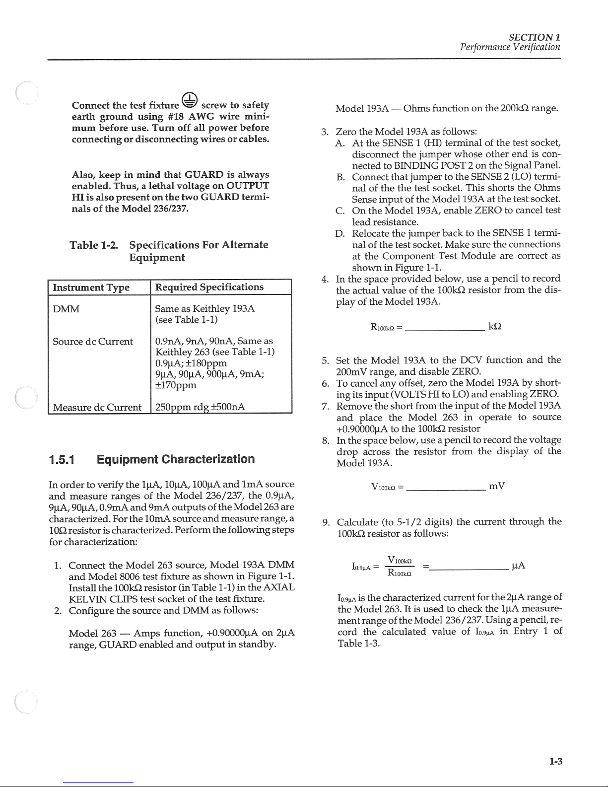
Connect
earth
mum
connecting
Also,
enabled.
HIisalso
nals
Table
Instrument
DMM
Source
Measure
1
.5.1
the
ground
before
keepinmmd
Thus,
present
of
the
1-2.
Type
dc
Current
Current
dc
Equipment
test
fixture
using
Turn
use.
or
discomtecting
that
a
lethal
on
the
Model
236/237.
Specifications
Equipment
Required
Same
(see
O.9nA,
Keithley
O.9iiA;
9iA,
±l7Oppm
25Oppm
Characterization
#18
off
voltage
Table
9OpA,
screw
AWG
power
all
wires
GUARD
GUARD
two
For
Specifications
Keithley
as
1-1)
9OnA,
9nA,
263
±l8Oppm
900pA,
rdg
to
wire
or
is
on
OUTPUT
Alternate
193A
Table
(see
±500nA
safety
mmi
before
cables.
always
termi
Same
9mA;
as
14)
Model
Zero
3.
At
A.
disconnect
nected
Connect
B.
nal
Sense
On
c.
lead
D.
Relocate
nal
at
shown
4.Inthe
actual
the
play
the
Set
5.
200mV
cancel
To
6.
its
ing
7.
Remove
and
+O.9OOOOiA
the
In
8.
drop
Model
193A
the
Model
the
of
the
resistance.
of
the
space
the
of
Riooico
Model
range,
input
the
place
space
across
193A.
Ohms
193A
SENSE
the
BINDING
to
jamper
that
the
the
input
of
Model
jumper
the
the
test
Component
in
Figure
provided
of
value
Model
=
193A
and
offset,
any
(VOLTS
short
Model
the
the
to
below,
the
functiononthe
follows:
as
1
terminal
(HI)
jumper
POST
to
socket,
test
Model
the
enable
193A,
back
socket.
Make
Test
1-1.
below,
lOOk2
the
193A.
the
to
disable
zero
HI
to
the
from
263
100kL2
resistor
useapencil
resistor
Performance
whose
on
2
SENSE
the
This
193A
ZERO
the
to
sure
Module
use
resistor
DCV
ZERO.
Model
the
and
LO)
of
input
in
operate
to
the
from
200k2
the
of
other
the
2
shorts
the
at
SENSE
the
are
pencil
a
from
ki2
ftmction
193A
enabling
the
record
display
SECTION
Verification
range.
socket
test
endiscon
Panel.
Signal
termi
(LO)
the
Ohms
socket.
test
to
cancel
termi
1
connections
correct
record
to
the
and
short
by
ZERO.
Model
to
source
voltage
the
of
1
test
as
dis
the
193A
the
order
In
and
9jaA,
characterized.
1O2
for
characterization:
1.
2.
verify
to
measure
O.9mA
9OjaA,
resistor
Connect
and
Model
Install
the
KELVIN
Configure
Model
GUARD
range,
ranges
and
the
For
is
characterized.
Model
the
8006
lOOk2
CLIPS
the
source
Amps
—
263
of
the
9mA
lOmA
263
fixture
test
resistor
socket
test
enabled
Model
outputs
source
Perform
source,
(in
of
DMM
and
function,
and
and
shown
as
Table
the
output
lOOj.tA
1OiA,
1iA,
the
imA
and
236/237,
of
the
Mode1263
measure
the
following
14)
test
follows:
193A
Figure
in
in
the
fixture.
Model
as
+O.90000pA
in
standby.
the
source
O.9iA,
range,
steps
DMM
1-1.
AXIAL
on
2i.tA
are
of
mV
current
the
for
the
Using
Io9&
through
2iA
1.tA
in
range
measure
pencil,
a
Entry
the
of
re
of
1
VOOk2
a
9.
Calculate
lOOk2
Io9=
IS
Io.9
Model
the
range
ment
the
cord
1-3.
Table
(to
resistor
VlOOk2
T)
lMOOki2
the
characterized
263.
ofthe
calculated
5-1
as
/2
follows:
lt
is
Model
digits)
=___________
used
current
value
the
check
to
236/237,
1-3
Page 30
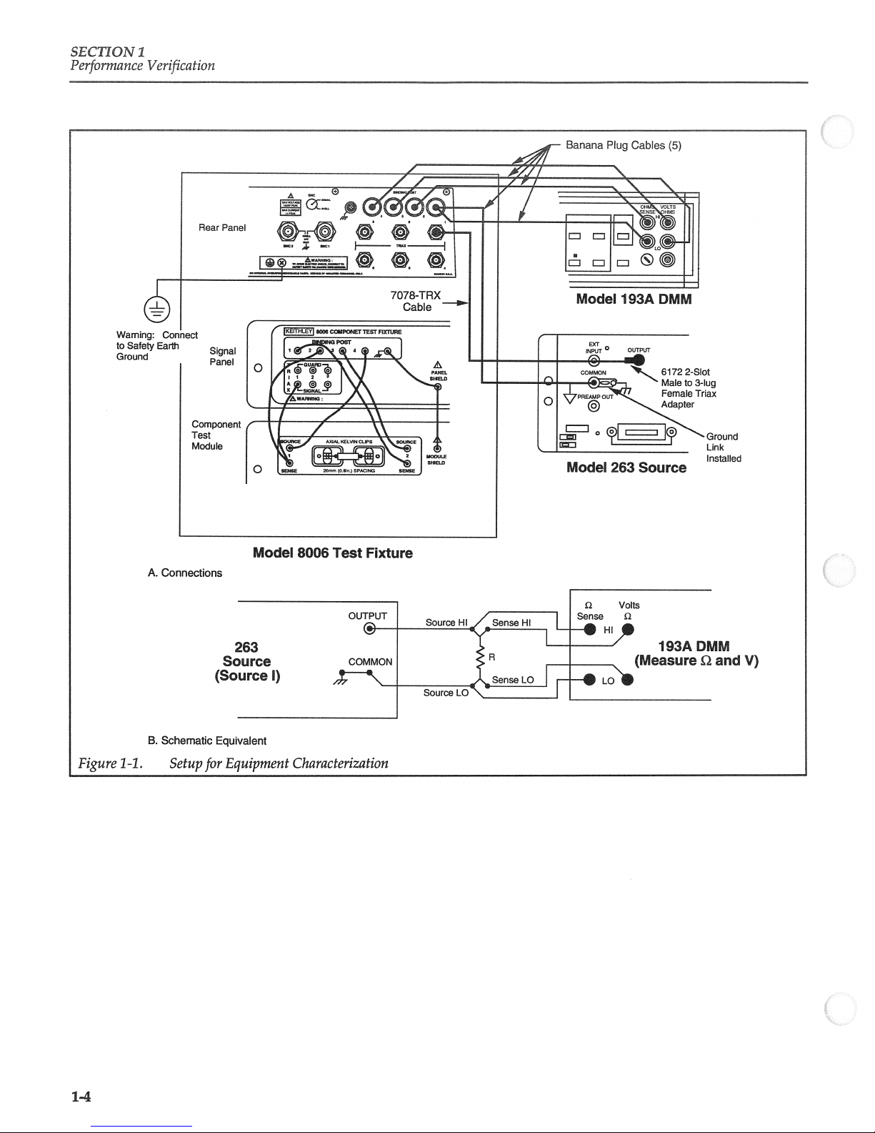
SECTION
Performance
Waming:
to
Safety
Ground
1
Verification
Banana
Model
Plug
263
Cables
Source
(5)
Ground
Link
Installed
Figure
14
A.
B.
.
Connections
Schematic
Setup
Model
8006
263
Source
(Source
Equivaent
Equipment Characterization
for
1)
Test
OUTPUT
COMMON
Fixture
Source
Source
LO
Volts
n
Hl
Sense
Sense
Sense
—7
193ADMM
(Measure
f2
and
V)
14
Page 31

Performance
SECTION
Verification
1
10.
11
12.
13.
Place
the
Set
the
Set
range
As
performed
across
I9=
the
Model
Model
and
the
VlOOk2
Model
enable
lOOk2
VlOOk2
Riooi
Entry Range
2
3
4
5
The
characterized
on
90-day
within
these
outofspecification.
263instandby.
193A
to
the
to
263
source
OPERATE,
in
steps
8
resistor
=
=
Table
263
1-3.
I-Source
Programmed Characterized
2iiA
2OjiA
2OOiA
2mA
2OmA
Isource
specifications
limits
2V
of
indicates
range.
9.0000j.tA
and9,measure
calculate
and
V
Model
263
Value
O9OOOOiA
9.0000iiA
90.000jiA
O.90000mA
9OOOOmA
shouldbewithin
values
Models
the
20j.tA
voltage
current.
263
the
calculation error,orthat
a
on
the
the
I-Source
ISource
IO9iA
Value Value
=_________
I9iA
I9O
Io.&
I
=_________
the
19.
listed
the
Set
193A.Acharacterized
and
and
To
20.
ing
21.
Remove
and
200j.tA
Record
22.
193A
Characteristics
I-Source
O.911A
9IiA
90!iA
O.9mA
9mA
These
limits.
Model
value
263
and/or
the Model
input
range
and
any
the
the
the
caiculate
Vk2
ZERO,
(VOLTS
short
Model
and
voltage
disable
cancel
its
set
±4.3nA
±54!iA
limits
that
Model
193A
offset,
from
enable
-______________
Limits*
±45OpA
±45nA
±43OnA
arc
based
not
to
zero
HI
fall
193A
is
DCV
the
to
LO)
inputofthe
the
source
to
does
263
OPERATE.
measurement
current.
the
and
Model
and
200mV
the
193A
enabling
Model
9O.OOOiA
from
the
mV
by
ZERO.
range,
short
193A
on
the
Model
IS
I9pA
the
Model
ment
cord the
Table
14.
Place
In
15.
6.
the
stall
the Model
On
the
range
17.
Repeat step3to
18.
Measure
the
characterized
263.
of
range
calculated
I-3.
the
Model
fixture,
test
lk2
disable
and
and
ltisused
the
Model
263
resistor
193A,
zero the
record
current
value
in
standby.
remove
(R-263-lk).
select
ZERO.
the value
check
to
236/237.
of
the
the Ohms
Model
for
1OOk2
of
R=
the
20j.tA
lOjiA
the
measure
Usingapencil,
in
I9LA
Entry
resistor
function,
W3A.
lki2
the
resistor.
1c12
range
and
2
2k2
re
in-
of
of
23.
24.
25.
26.
I9OA
IS
I9OA
of
the
urement
record
Table
Place
the
Set
Set
the
range,
Record
193A
IO.9mA
the
of
urement
the
characterized
Model
range
the
1-3.
Model
the
Model
Model
and
the
caiculate
and
the
IS
Model
range
V
1k2
11kQ
ltisused
263.
Model
ofthe
calculated
in
263
193A
to
source
to
263
enable
voltage
OPERATE.
measurement
the
characterized
ltisused
263.
Model
ofthe
to
for
check
current
236/237.
value
of
I9OA
standby.
the2Vrange.
O.90000mA
current.
to
for
check
current
236/237.
the
the
Using
in
from
the
the
Using
2OO.tA
1OO.tA
range
meas
a
pendil,
Entry3of
on
the
the
Model
2mA
range
1mA
meas
a
pencil,
2mA
15
Page 32

SECTION
Performance
1.
Verification
27.
28.
29.
30.
31.
32.
33,
34,
35,
I09mA
record
Table
Place
In
the
the
1002
On
the
range
Repeat
Measure
the
Set
disable
To
cancel
ing
its
Remove
and
set
2OmA
Record
193A
and
I9mA=
Vikfl=
the
the
test
Model
and
step
Rb000
Model
ZERO.
input
the
range
the
v
1000
Vb000
—
Rbooo
calculated
Model
fixture,
resistor
disable
3
and
=
any
(VOLTS
the
short
Model
and
voltage
cakulate
vb00
Rb000
=______________________
value
263instandby.
remove
(R-249400).
193A,
select
ZERO.
zero
to
record
offset,
the
the
193A
to
zero the Model
FR
from
263tosource
enable
measurement
the
=_________________
V
of
Io
the
lk2
resistor
the
Ohms
Model
193A.
valueofthe 1002
DCV
and
the2Vrange,
and
to
the
LO)
input
enabling
of
the
9.0000mA
OPERATE.
from
current.
v
mA
in
Entry
and
function,
resistor.
193A
by
Model
the
mA
4
install
2OO
and
short
ZERO.
193A
the
on
Model
4L
Remove
and
42.
Record
193A
of
43,
Caiculate
place
and
the
short
the
the
voltage
then
V1oi2
=
the actual
from
Model
measurement
place
263inoperate.
the Model
resistanceofthe
input
the
the
Model
of
from
in
263
standby.
193A
the
Model
mV
1O2
resistor
as
follows:
v‘o
2
=
I9mA
15
I9mA
used
to
of
the
Model
Common
=_________________________
obtained
verify
from
the
236/237.
Mode
equipmentasshown
for
common
program
LINECYCLE
at
compliance
236/237
the
voltage
in
TIME
1
the
record
steps
standby,
and
Model
below.
Table
lOOmA
source
Verification
in
Figure
mode
Mode1236/237
the
PERIOD,
iv
at
OPERATE
in
measurement
13.
and
and
12
verification,
source
on
1.1V
the
and,
in
measure
perform
as
range.
using
the
space
fo1
at
a
where;
R1ois
range
1
52
Set
up
the
following
1.
While
lows;
+1,0000jiA,
2.
Place
pencil,
provided
Rio
the
15
the
I9niA
of
the
urement
record
characterized
Mode1263.
range
the
calculated
ofthe
lt
used
is
Model
current
value
check
to
236/237.
of
Table
36.
Place
the
37,Inthe
stall
On
38.
the
39,
While
the
40.
Zero
HI
to
test
the
the
Model
200mv
in
2OmA
the
LO)
Model
1O2
standby,
Model
263instandby.
fixture,
resistor
193A
range.
DC
set
range.
193Abyshorting
enabling
and
remove the
(R48540).
DMM,
the
Mode1263
disable
ZERO.
1OO2
14
for
Io
the
the
ZERO
to
its
2OmA
lOmA
Using
a
in Entry
resistor
and
+9.0000mA
input
(VOLTS
range
meas
pendil,
5
and
seledt
in
on
of
3,
From
4.OOOOjiA
4,
Subtract
other,
<15ov.
v÷1M=
the
V-1=
the
verif
3
keypad,
and
record
two
that
v+bAvbA
change
that
voltage
the
absolute
v
the
source
measurement.
v
measurements
value
<15O.tV
of
the
value
from
result
to
each
is
Page 33

nterlock
Cable
Performance
SECTION
Verification
1
Waming:
Safety
to
Ground
@@@
!__H
F—
A.
z
8006
Connections
Test
p
z
Fixture
F—
Shorted
Output
Schematic
B.
for
Common
1-2.
Figure
Setup
Equivalent
Mode
Verification
1-7
Page 34

SECTION
Performance
1
53
Setup
the
the
following
The
voltages
cause
tion
levels.
1.
Set
the Model
range.
2.
While
the
1.1V
3,
Temporarily
BINDING
fixture
193A.
DMM.
1.
Verification
Voltage
equipment
stepstoverify
following
(1000V
injury
when
encountering
in
standby,
range
POST
and
connect
This
will
Source
as
shown
WARNING
procedure
forthe
or
death,
193A
to
set
the
and
set
disconnect
2
at the
it
short
Veritication
in
Figure
the
voltage
uses
Model
Exercise
these
measure
Model
compliance
the
rear
panel
to
VOLTS
the
inputofthe
13
and
source.
hazardous
237)that
extreme
lethal
DCV
could
voltage
on
the
cau
236tosource
to
lOmA.
banana
cable
panelofthe
LOofthe Model
Model
perform
200mV
0V
from
test
193A
on
4,
5.
6.
7,
8.
9,
10.
11.
12.
On
the
Model
urement
Re-connect
the
Place
the
in
ing
Press
and
able
Using
OV
From
+1V
193A
Repeat
Using
±10V,
fixture.
test
the
reading
the
first
is
noisy.
the
verify
limits
Table
output
the
on
the
DMM
step9forasource
Table
±100V
Program
standby.
193A,
press
ZERO
to
offsets,
the
Model
on
entry
banana
the
ofTable
cable to
236/237
in
DMMiswithin
14.
BINDING
operate
the
Use
SELECT4buttontoselect
that
the
DMM
readingis
in
1-4
on
keypad,
1.1V
is
Table
as
the
range
within
1-4.
guide,
a
110V
program
and
the
repeat
and
1100V
the
verify
allowable
Model
that
valueof—1V.
1-4
as
a
the
and
Model
for
guide,
the
236/237
Model
check
237,
to
0V
cancel
and
the
ifiter
within
step
ranges
reading
limits.
source
±1000V.
and
any
POST2of
verify
limits
ifthe
the
11V
the
7tocheck
236
to
values
placeitin
meas
that
shown
read
range
allow
the
source
on
the
of
Source
—
236/237
Value*
0V
0V
0V
0V
+1V
-1V
+10V
-10V
+100V
—100V
+1000V
—1000V
compliance
Source
is
set
Table
236/237
Range
1.1V
11V
110V
1100V
1.1V
1.1V
11V
11V
110V
110V
1100V
1100V
to
lOmA.
14.
Voltage
Source
Verification
Allowable
193A
Range
200mV
200mV -2.400mV
200mV
—24,000mV
2V
2V
+0.99902V
2V
20V
20V
200V
200V
1000V
1000V
Reading
(18°C
-0.650mV
-0.240V
-0.99902V
+99943V
-99943V
+99.943V
-99,943V
+999.36V
—999.36V
to
to
to
to
to
to
to
to
to
to
to
to
to
28°C)
on
Model
+0.650mV
+2,400mV
+24000mV
+0.240V
+100098V
-1
00098V
+100057V
—100057V
+100.057V
—100.057V
+1000,64V
—1000.64V
193A
1-8
Page 35

Waming:
to
Safety
Ground
SECTION
Performance
1
Verification
1
Figure
1
54
Set
the
L
1-3.
the
up
following
The
voltages
cause
when
tion
levels.
While
measure
current
Cönnections
A.
Schematic
B.
Setup
Voltage
equipment
steps
following
(1000V
injury
encountering
in
standby,
volts
source
for
Measure
shown
verify
to
WARNING
procedure
for
or
death
configure
setting
by
range.
Test
8006
236/237
(Source
Equivalent
Voltage
in
voltage
the
Model
Exercise
these
it
to
Fixture
OUTPUTHI
V)
OUTPUT
Ranges
Source
Verification
Figure
14
measurement:
hazardous
uses
that
237)
extreme
lethal
the Model
source
OnA
Verification
perform
and
could
cau
voltage
236/237
the
on
®—
inA
Volts
2.
3,
4.
While
output
On
L1V
Place
the
in
0V
on
the
—H1
.
standby,
on
Model
1.1V
the
calibrator
LO
the
10V
236/237,
measurement
193A
(Measure
the
set
range.
the
and
DMM
V)
Model
set
343A
voltage
range.
Model 236/237
calibrator
compliance
in
to
to
oper-
ate.
limits
and
on the
listed
limit
verify
ta
5.
6.
Verify
Model
in
the
the
On
11V
to
that
that
236/237
Erst
Model
the
entry
the
on
voltage
measured
the
is
236/237,
11V
reading
within
Table
of
change
measurement
the
1-5.
is
voltage
allowable
within
reading
compliance
the
range
the
limitsinthe
hie.
measure
to
step
repeat
guide,
as a
1-5
Tabie
Using
7.
measurement
110V
the
on
OV
caiibrator
the
Set
to
8.
Modei
the
set
and
the
1.1V
on
1.1V
1100V
and
output
to
236/237
measurement
for
+1V
a
range.
6
the
on
compliance
Verify
ranges.
10V
limit
that
range,
of
the
1-9
Page 36

SECTION
Performance
1
Verification
voltage
allowable
9,
Repeat
reading
limitsinthe
step
8
using
A.
Connections
on
the
Model
table.
a
calibrator
236/237iswithin
output
8006
Test
of
Fixture
-4V.
the
10.
11.
Using
puts
Place
Table
1-5
of
±10V,
the
Model 236/237
DC
a
as
±100V
Calibrator
guide,
and
measure
±1000V
in
standby.
calibrator
(Model
237
out
only).
Figure
140
1-4.
B.
Schematic
Setupfor
Equivalent
VoltageMeasure
Ranges
Verification
Page 37

Perfonnance
SECTION
Verification
1
343A
*236/237
Range
1OV
1OV
1OV
10V
10V
10V
10V
10V
100V
100V
1000V
1000V
settosource
343A
OnA
Table
Output
OV
0V
OV
0V
+1V
—1V
+10V
40V
+100V
—100V
+1000V
—1000V
inA
on
source
15.
range.
Voltage
236/237
Compliance
Measure
&
1.1V
11V
110V
1100V
1.1V
1.1V
11V
11V
110V
110V
1100V
1100V
Measure
Limit
Range*
Verification
Allowable
ftOOO3OV
OO.OO1OV
OOOO1OV
0000.10V
+0.99942V
0.99942V
+9.9965V
—9.9965V
+99.965V
—99.965V
+999.55V
—999.55V
(18°C
to
28°C)
to
to
to
to
to
to
to
to
to
to
to
to
Reading
+ft0003OV
+OftOOlOV
+000.010V
+0000.10V
+1.00058V
—1
.00058V
+10,0035V
—10.0035V
+100.035V
—100.035V
+1000.45V
—1000.45V
1
55
up
Set
sistor
(R2634k)
formthe
When
mote
sentonthe
when
programmed
possible
power
cables
sociated
Remote
the
equipment
following
Model
a
sensing,
unit
the
shock
before
the
to
test
is
installed
steps
hazardous
SENSE
is
voltage
Source
fixture.
Sense
shown
as
in the
verify
to
WARNING
and
in
operate
hazard,
Measure
is
or
236/237
connecting
Verification
Figure
in
Kelvin
remote
programmed
voltage
OUTPUT
regardiess
current.
always
or
1-5.
test
sense
may
terminals
To
hirn
disconnecting
or
Unit
The
socket.
accuracy:
for
pre
be
of
avoid
off
the
re
the
all
as
1ki
a
Per
in
select
remote
Place
the
limit
the
20V
theMode1236/237
the
lOmA
in
193A
place
source
measurement
standby.
DMM to
10V
with
DCV
compliance
a
range.
and
in
and
lOmA
standby,
setitto
on
1.
While
sense
of
Model 236/237
re
Set
2.
the
Model
range.
from
panel
ZERO
and
the
and
cable
of
the test
VOLTS
it
to
Model
of
the
cancel
to
POST
verify
following
local sense.
1
that
of
a1
Temporarily
3,
VOLTS
fixture
LO
193A
4,
On
any
Reconnect
5,
the
Place
6.
the
lowable
Place
7,
HI
(BINDING
the
of
DMM.
Model
the
offsets.
fixture.
test
the
reading
limit;
the
of
DMM.
the
Model
on the
Model
disconnect
DMM
the
POST
This
DMM,
193A
banana
236/237
DMM
9.99500
236/237
at
1),
shorts
cable
V
to
in
in
is
the
banana
the
rear
connect
and
input
the
enable
BINDING
to
operate
within
10.00500V.
standby
141
Page 38

SECYION
Performance
1
Verif-ication
Waming:
Safety
to
Ground
Connect
Earth
‚
1_
‚=‘
0
—
Connections
A.
:
0,
z
.
‘@@‘,
(Source
::
‚
8006
236/237
SENSE
A
@:
Test
V)
‚ØØ
Fixture
OUTPUT
SENSE
LO/OUTPUT
LO
Cable
(236-lLC3)
7O78TRX
Cables
IfllH
1
193ADMM
236/237
UOBIOiLQDU:QNBOU
(3)
Banane
Cables
(2)
Plug
00
ntertock
H
HI
B.
Schematic
Figure
t56
Setup
the
1-5.
Low
Measure
the
equipmentasshown
following
steps
Setup
Current
for
Ranges
verify
to
Remote
ranges:
L
Use
the
I9tA,
and
Table
ljiA
through
I9OA,
recorded
1-6
IO9mA
to
caiculate
lOniA
and
in
IL
Table
readings, transfer themtoTable
Whileinstandby,
2.
measure
source
142
currentby
range.
configure the
settingittosource
Equivalent
Sense
(inA
Verification
Figure
in
the
inA
allowable
the
ranges.
were
13.
After
Verification
lOmA)
to
16
and
lOmA
to
values
The
previously
caiculating
17.
Model 236/327
0V
perform
measure
readings
for
calculated
on
the
for
Io,
these
1.1V
2nA
the
in
enable
the
Verify
entry
the
lOnA
reading
ranges
standby,
GUARD.
compliance
inA
measurement
that
is
within
236
of
Table
Model
the
on
on
specified
Table
17,
with
236/237,
lOnA
this
in
check
While
3,
and
4,
Setthe
on
ATE.
Model
first
On
5,
to
the
lirnits
Using
to
6.
rent
Mode1263
set
limit
ofthe
range
current
the
allowable
the
17.
change
measurement
measurement
the
table.
the
rest
the
output
Mode1236/237
measurement
of
of
the
to
and
enable
limits
the
compliance
range.
rangeiswithin
Model
the
Model
the
listed
Verify
range
to
OPER
on
in
limit
236
263
lnA
the
the
that
the
cur
in
standby.
Page 39

Performance
SECTION
Verification
1
7.
Set
range,
to
Verify
8.
in
On
9,
Figure
the
inA
the
the
1-6.
Model
and
set
on
the
the
that
table.
Mode1263,
Note
Setup
263tooutput
the Model
lnA
measuiement
236/237
readingiswithin
change
the
LZJ
Source
263
(Source
:
263
GUARD
Low
Current
for
+O.90000nA
compliance
range.
the
limits
output
to
1)
enabled
Measure
on
the
specified
negative
Ranges
2nA
limit
po
Verification
10.
11.
larity
specified
Using
lOmA
Place
(inA
and
verify
in the
Table
measurement
Model
the
to
lOrnA)
the
reading
that
table.
1-7
guide,
as
a
in
263
10000Boo
ranges
standby.
check
of
the
6ö:
LiQo
within
is
the
Model
lOnA
the
limits
through
236/237.
Table
236/237
Measure
Range
1iA
lOjiA
lOOjiA
1mJ
lOmA
*
IO9pA,
**
Allowable
***
fle
Model
263
1=6.
Reading
+IO9M
Allowable
Calculations*
±
(0.0004)
[
Reading
IO.9A
—Io.9±[(O.OOO4)Io9+6OpAJ=
+I9±[(O.OOO35)I9+7OOpA1=
±
—I9A
+I9OpA
49OA
(0.00035)
[
±
(0.00035)
[
±
(0.00035)
[
+IO9mA±[(O.00035)IO.9mA+6OflAj
I9iA
I
9o
I9O
—Io.mt±[(O.OOO35)Iosmi+6OnA1
+I9mA
±
(0.00038)
[
Im
—I±[(O.OOO38)I+6OOnA]=
I9A,
I9OiA,
reading
calculated
263
and/or
and
Model
and
IO9mA
limits
allowable
A
193A.
193A
calculated
is
are
I9flA
aretobe
readings
out
obtained
transferred
should
allowable
specification.
of
+
700pA
+
+
+
+
6OpA
6flA
6nA
600flA
Caiculations
1
=
1
=
1
1
=
1
Table
from
Table
to
the
within
be
reading
1-3.
1-7.
listed
that
for
Lower
.
+
—.
+.__jiA
—
.
+
—
+.
.
+
.
—.mA
typicallimits.
does
Low
Allowable
Limit
.
.
—
not
fall
Current
i.LA
iiA
iiA
LA
jiA
iiiA
flLA
iiiA
within
Readmg**
Upper
+
—_.
+._A
—
+
—
+.
+
—.mA
These
these
Measure
.
•
.
.
limits
limits
Limit
.
.
are
indicates
.
—
based
jiA
iA
ilA
iA
fltA
Verification
Typical
Limits***
jiA
+O.90000iiA
—O.90000jiA±87OpA
+9.0000j.tA±8nA
—9.0000pA
+9O.OOOLA
—9O.OOOiA
+O.900001TLA±800flA
IflA
iflA
0.90000fllA±800flA
+9.0000mA
—9.OOOOmA±9.4iA
the
90-day
on
caiculation
a
error, or
to
(1iA
±87OpA
±8nA
±83nA
±83nA
±9.4iA
specifications
that
lOmA)
of
the
the
Model
143
Page 40

SECTION
Performance
1.
Verification
263
Range
2nA
2riA
2nA
2nA
2nA
2nA
2nA
2nA
2nA
2nA
2OnA
2OnA
200nA
200nA
2iiA
2jiA
Table
263
17.
Output
Standby
Standby
Standby
Standby
Standby
Standby
Standby
Standby
+O.90000nA
—O.90000nA
+9OOOOnA
—9.0000nA
+9OOOOnA
9O.OOOnA
+ft9OOOOiA
-O.9OOOOiA
Low
Current
236/237
Compliance
Measure
&
inA
lOnA
lOOnA
ljiA
lOiiA
OOjiA
imA
lOmA
inA
inA
lOnA
lOnA
lOOnA
lOOnA
1iA
liiA
Measure
Limit
Range*
Verification
Allowable
to
(18°C
28°C)
—O.OOO1OnA
OOOO1OnA
OOO.OO6nA
O.OOOO6jiA
OO.OOO7jiA
—OOO.OO6tA
-OOOOO6mA
OOOOO6mA
O.8972OnA
+O.8972OnA
—&972OnA
+&972OnA
-898O5nA
+89.8O5nA
-
+
to
(inA
Readings**
to
+O.000lOnA
+OO.00lOnA
to
+000.006nA
to
+OOOOO6jiA
to
+OOOOO7jiA
to
to
+OOO.OO6iA
to
+OOOOO6mA
+Oft0006mA
to
+O.9O28OnA
to
—O9O28OnA
to
9.O28OnA
to
+9O28OnA
to
—90.195nA
to
+90.195nA
to
to
to
+___________
lOmA)
2OiA
2OjiA
200jiA
200jaA
2mA
2mA
2OmA
2OmA
*236/237
**Allowable
set
+9.0000jiA
9.OOOOjiA
+9OOOOjiA
9O.OOOiA
+O9OOOOmA
-ft90000mA
+9.0000mA
—9.0000mA
for
0V
on the
the
source
to
readings
lj.tA
1,1V
thru
lOjiA
lOjiA
lOOjiA
lOOjiA
imA
imA
OmA
lOmA
source
lOmA
range.
ranges
—
+
-
+
+
—
+
are calculated
in
Table
1-6.
to
to
+___________
to
to
+____________
to
—____________
to
+___________
to
—____________
to
+____________
144
Page 41

Performance
SECTION
Verification
1
1
.5.7
the
Set
up
following steps
the
ranges:
1.
Use
Table
the
ljiA
I9OpA,
I9tA,
recorded
and
lowable
While in
2.
source
ance
While
3.
on
OnA
4.
With
617
on
5.
On
the
the
Model
ingonthe
the
first
Set
the
6.
Model
the
that
specified
7.
Using
source
Current
Low
Source
equipment
1-8
to
through
and
IO9mA
in
readings,
standby,
OnAonthe
limitof1.1V
standby,
in
2nA
the
ZERO
CHECK
2pA
236/237
Model
to
in
the
1-9
on
range.
617,
of
617
source
the
the
Model
entry
Model
236
reading
Table
zero
Ranges
as
shown
to
verify the
caiculate
OmA
IA
Table
transfer
configure
lnA
on
the
configure
range.
enabled,
disable
in
is
617
Table
to
OnA
the
on
second
guide,
a
as
lOOnA
(1
nA
Verification
in Figure
the allowable
ranges.
were
After
1-3.
them
the
source
1.1V
the Model
zero
ZERO
operate.
within
1-9.
2OpA
the
the
on
Model
of
entry
set
through
1
OmA)
to
17
and
to
lOmA
inA
readings
The
values
previously
caiculating
Table
the
Model
with
range
measurement
263
correct
CHECK
Verify
that
the limits
range,
range.
lOnA
is
within
617
1-9.
Table
Model
the
lOmA
perform
source
for
calculated
the
1-9.
236/237
compli
a
range.
source
to
Model
the
and
the
specified
and
set
Verify
limits
the
236/237
ranges
for
IO9A,
a1
place
read
the
and
select
to
source
operate,
Verify
thelimits
Models
the
that
limits
the
proce
through
through
Model
the
the
it
po
to
and
the
are
within
and
program
and
263
in
263
617,
within
the
and
reverse
Mode1236/237
operate,
in
Verify
within
basic
the
lOnA
the
ljiA
the
the
for
the Models
and
in
inA
set
236/237
Model
zero
in
and
263
the
617
guide,
14
Note
Table
zero
in
readings
zero
standby
in
source
the
on
236/237,
set
to
and
Model
is
repeat
check
to
that
values
check
range.
Model
and
Model
the
617
is
check,
the
—O.9nA.
263
617.
still
for
1-3.
check,
the
Model
Model
in
the
ZERO
in
Model
Models
sources.
Models
on
in
are
Model
subsequent
236/237
on
standby,
2nA
Models
on
table.
the
617
in
Model
the
check
Model
the
the
table.
as
1-9
through
8
ranges.
the
taken
617
in
617
the
range.
CHECK
the
standby.
263
Thatis,
236/237
on
a
source
from
standby.
that
check
limits.
listed
the
Place
8.
2OpA
range.
Place
source
While
+O.9nA
Place
and
disable
that
the
the
—O.9nA
stffl
on the
both
reading
9,
10.
11.
specified
to
12.
13.
14.
Place
and
263
On
both
larity
+O.9nA
Place
disable
the
236/237
the
ofthe
and
the
zero
reading
in
15,
specified
Using
in
dure
1OmA
lOmA
Table
steps
source
ranges,
236/237
the
Place
to
16.
263
and
236/237
Table
1-8,
Source
*
**
***
Allowable
236/237
Range
1iA
lOj.tA
1OO.tA
lmA
lOmA
I9tA,
IO9A,
Allowable
calculated
The
fications
caiculation
I9OiA,
reading
of
the
error,
Reading
±
(0.0005)
[
±
(0.00050)
[
(0.00050)
±
[
±
(0.00050)
[
±
(0.0005)
[
and
IO9mA
limits
allowable
Model
that
or
Reading
Calculations*
I9A
are
to
readings
and
263
Model
the
Caiculations
200pA
+
IO
9
2.00nA
+
I9LA
20.00nA
I9o+
200.OflA
+
IO9mA
I9mA
+
2.00i.tA
transferred
should
be
263
and/or
from
obtained
are
be
193A.Acalculated
1
1
1
Table
to
within
Model
for
=
=
=
j
1
=
Table
the
allowable
1-3.
1-9.
listed
193A
Low
Lower
—
—
—
—
typicallimits.
reading
out
is
Current
Allowable
Limit
.
.
.
.
.
that
specification.
of
nA
nA
jaA
does
nA
LA
These
Source
Reading**
Upper
+
+
+
+
+
not
Verification
.
.
.
.
.
are
limits
within
fall
Limit
nA
nA
j.tA
based
these
nA
iA
on
limits
to
(lj.tA
Typical
Limits***
±O.6500nA
±6.500nA
±65.00nA
±O.65OO.tA
±6.500jiA
the 90-day
indicates
lOmA)
speci
a
1-15
Page 42

SECTION
Performance
1
Verification
Figure
1-7.
B.
Schematic
Setupfor
2361237
Equivalent
Low
Current
OUTPUT
Source
H
Ranges
Verification
Note
Eiectrometer
(Measure
(inAtolOmA)
617
Electrometer
:
617
GUARD
dualled
OUTPUT
COMMON
263
Source
(Source
1)
1)
146
Page 43

Performance
SECTION
Verification
1.
Table
263
617
Range Range
2pA
2pA
2OpA
200pA
2nA
2OnA
200nA
2jiA
2OpA
200pA
200pA
2nA
2nA
2nA
2nA
2nA
2nA
2nA
2nA
2nA
2nA
2OnA
200nA
2jiA
1-9.
I=Source
Output
Setting
Standby
Standby
Standby
Standby
Standby
Standby
Standby
Standby
+O.9nA
—O.9nA
+9nA
-9nA
+9OnA
—9OnA
+O.9iA
—O.9iaA
Low
Current
236/237
Source
Range
inA
lOnA
lOOnA
ljiA
1OiA
lOOjiA
lmA
lOmA
inA
lOnA
lOOnA
1iA
Source
ISource*
Verification
Source
Value***
OnA
OnA
OnA
OjiA
OjiA
OjiA
OmA
OmA
—O9nA
+O9nA
—9nA
+9nA
-9OnA
+9OnA
4O.9LA
+k9A
(inA
617
Allowable
to
(18°C
ft45OOpA
—2.000pA
-2OOOpA
—200.OpA
—2.000nA
—20.00nA
—200.OnA
—2.000jiA
315OpA
—29OOpA
—209.OpA
to
28°C)
lOmA)
Readings**
+O.4500pA
to
+2.000pA
to
+20.00pA
to
+200.OpA
to
+2.000nA
to
+20.00nA
to
+200.OnA
to
+2.000jiA
to
+3J5OpA
to
+29.00pA
to
+209.OpA
to
+nA
to
2OnA
200nA
2iA
2jiA
*
236/237
**
Allowable
***
For
compliance
ljtA
the
2OjiA
200jiA
2mA
2OmA
readings
thru
limit set
for
lOmA
+9jiA
—9jiA
+9OjiA
—9OpA
+O.9mA
—O.9mA
+9mA
—9mA
to
1A
the
ranges,
11V
on
thru
program
the
lOmA
the
1OiA
lOOjiA
imA
lOmA
measurement
UV
ranges
source
Mode1236/237
+I9iA
—I9O
+I9O
—Io.9
+IO9mA
—I
+I9mA
range.
are calculated
source
to
—tA
-tA
in
characterized
the
flA
Table
18.
Isource
to
to
to
to
+nA
+
+______
+tA
valued
nA
from
Table
1-3.
1-17
Page 44

SECTION
Performance
1
58
up
the
Set
sistor
(R-18540)
1
Verification
1
OOmA
Measure
Verification
equipment
is
installed
Range
as
showninFigure
in
the
test
1-8.
sockeL
The
1O2
7.
Verify
236/237
that
the
current
Within
jS
the
reading
following
(b)
limits:
on
the
Model
re
I
±6pA
=
Io
procedure
This
1O2
resistor
value
of
paragraph
space
Perform
urement
1.
While
OVonthe
lOOmA.
Set
2.
Zero
3,
HI
4,
Remove
and
2500E)
Place
5.
voltage
space
Caiculate
6.
follows:
this
of
provided
the
rance
the
to
set
requires
for
current
resistor
1.5.1.
below:
R
—
10
following
c‘
in
standby,
1.1V
Model
the
Model
and
LO),
the
short
the
output
to
the
Model
measurement
below:
VOrnA=
the
caiculations.
was
Transfer
steps
set
source
193A
to
193A
enabling
from
calibration
OmA.
236/237
actual
characterized value
the
previously
resistance
that
verify the
to
Model
the
range,
the
by
and
2V
dc
shorting
ZERO.
input
the
source
operate
in
from
the
current
through
The
recorded
236/237
compliance
set
range.
its
input
of
the Model
(Models
and
Model
v
the resistor
characterized
in
value
lOOmA
to
(VOLTS
343A
record
193A
of
step
to
meas
source
193A
and
in the
the
43
the
the
to
as
Set
8.
9.
1O•
the
Record
late
the
I+9OmA
Velif)7
236/237
ii.
12.
13.
the
Set
Record
late
the
L-9OmA
Verify
236/237iSwithin
calibration
the
actual
V+9A
that
is
1236
voltage
V+9QmA
within
current.
—
Rion
the
current
I+9OmA
source
from the
=______________________
the
±((O.0008)
calibration source
the
actual
v
90
that
voltage
V-9OmA
Rio
the
from
current.
=
=______________________
current
the
output
to
Model
reading
following
I+9OmA
output
to
the
Model
reading
following
193A
V
(I)
limits:
+6.tA}
—9OmA.
93A
v
(b)
limits:
+9OmA.
and
mA
on
the
and
inA
the
on
calcu
Model
calcu
Model
IOmA=
VoA
RioQ
=___________
1-18
mA
14.
Place
1236
the
I-9OmA
Models
±((O.0008)
343A
and
I-omj
+6i.tA}
236/237instandby.
Page 45

Waming:
to
Safety
Ground
Earth
Performance
SECTION
Verification
1
Figure
1-8.
Connections
A.
343A
DCCalibrator
8.
Schematic
Setup
for
lOOmA
Source
Equivalent
+
.-
Measure
Range
2500
Current
Calibrator
(Source
—.
+
OUT
IN
-.-.-
Verification
.:.
o
1
93A
DMM
E
1)
1O2
—€
236/237
(7
(Measure
OUTPUTFU
6ö
Qo
1)
-::T
149
Page 46

SECTION
Performance
1
5
9
Setupthe
sistor
(R485-1O)
1
Verification
1
OOmA
equipment
is
Source
showninFigure
as
installed
in
Range
the test
Verification
1-9.
sockeL
The
1O2
7
Verify
lowing
that
limits:
the
current
(JOmA)
15
withrn the
fol
actual
re
OIflA
JOmA
±2OLA
This
procedure
lfl(2
resistor
value
of
this
of
paragraph
graph.
vided
Transfer
below:
Perform the
range:
While
1.
OmA
1.1V.
to
2.
3,
4,
5.
the
Set
Zero
HI to
Remove
Place
voltage
svace
for
resistor
1.5.1
Rio
following
in
standby,
on
the
Model
the
Model
LO),
and
the
the
Model
measurement
below:
V0m=
requires
current
was
and
that
resistance
=
lOOmA
193Atothe
193A
enabling
short
from
236/237
the
characterized
caiculations.
previously recorded
also
used
in
valuetothe
the
by
the
from
to
Model
shorting
ZERO.
in
verify
range
2V
dc
inputofthe
operate
the Model
steps
set
source
The
the
the
236/237
and
range.
its
V
value
characterized
in
previous
space
lOOmA
to
compliance
set
input
(VOLTS
Model
and
record
193A
of
step
para
pro-
source
source
193A.
in the
the
the
43
10.
11.
12.
8.
9
Set
the
Record
late
the
I+9OmA
Verify
lowing
Set
the
Record
late
the
L9o
Model 236/237
the voltage
current.
actual
V÷9omA
V+9QmA
Rio
the
actual
that
limits:
I+9OmA
Model
the
actual
V9o
=
89.9141flA
236/237
voltage from the
current.
=
7
v
-9OmA
Rwe
to
from the
output
Model
+9OmA.
193A
V
=______________________
current
to
(I+9o)
90.0861UA
to
output
Model
within
is
-9OmA.
193A
V
=______________________
inA
mA
and
and
calcu
the
calcu
fol
6.
follows:
Calculate
Io=
the
actual
VoA
R
1o0
current
=___________
through
the resistor
mA
as
13.
14.
Verify
limits:
Place
that
L9OmA
the
the
=
Model
actual
current
89,914fllA
236/237
to
in
standby.
is
within
90.O86IflA
the
following
1-20
Page 47

Perforinance Verification
SECTION
1
121
Page 48

Page 49

SECTION
.
calibration
2
2i
Calibration
the
shows
any
error,
manual.
sentative
Calibration
IEEE-488
bration
INTRODUCTION
performance
that
of
the calibration
refer
If
or
bus.
procedures,
QuickBASIC
Manufacturer
should
the
to
the
the
of
that
be
verification
Model
the
troubleshooting
problem
factory
the
Model
This
section
and
canbeused.
performed
236/237
cannot
steps
persists,
for
further
236/237
contains
a
program
Model
every
procedure
is
out
be
information
call
your
information.
is
performed
the
written
12
months, or
(Section
of
specifications.
performed
Keithley
stepbystep
in
Table
24.
Description
without
in this
repre
over
the
ca1i
Microsoft
Required
1)
Before
sure
the Model
tor‘s
if
If
22
attempting
you
are
Manual
236/237.
any
of
famffiar
for
with
Refertothe Model
complete information.
RECOMMENDED
the following
the controls
CALIBRATION
procedures,
and
Operation
236/237
make
of
Opera
EQUIPMENT
Table
24
lists
that
Note
9Oday
the
specifications
equipment
leastasgood
Test
Equipment
Specifications
recommended
Models
may
be
as
the
263
as
usedaslongastheir
specifications
and
listed
calibration
193A
must
in
the
listed
within
be
table.
accuracy
in
the
equipment.
their
Alternate
is
Table
2-2.
at
Keithley
Keithley
Keithley
Keithley
263
193A
8006
R-185-10
R-249-100
R-263-lk
R-263-100K
5-1/2digit
Calibrator/Source
5-1
digit
/2
Test
102
1002
1k2
100k2
Resistor
DMM
Fixture
Resistor
Resistor
Resistor
2nA,
2OnA
200nA
200mV,
20V-1000V
2002-200k2
±OJ%,
±0.1%,
±0.1%,
±0.1%.
range;
2V
±10
±20
±10
±10
ranges;
±(O.035%
ranges;
ranges;
ranges;
ppm/°C
ppm/°C
ppm/°C
pvm/°C
±(OO625%
10
+
±(ft005%
±(0.007%
±(0.007%+2
10
+
counts)
2
counts)
+
1
+
count)
counts)
counts)
2-1
Page 50

SECTION
Calibration
2
22,
Table
Specifications
For
Alternate
Equipment
23
Calibration
ditions
a
2A
ENVIRONMENTAL
having
relative
WARMUP
The
3wire
ground
grounded
are
power
outlet
electric shock,
should
hiimidity
Source
power
wire
made,
line
may
be
an
ambient
of
PERIOD
WARNING
Measure
cord
and
outlets.
instrument
ground.
result
Instrument
DMM
SourcedcCurrent
CONDITIONS
performed
temperature
less
than
Unit
that
is
designed
When
Failure
in
under
70%.
is
equipped
contains
proper
chassisisconnected
to
injury
or
Type
laboratory
of23°C
tobeused
connections
useagrounded
death
a
separate
±1°C
with
with
due
to
to
a
O.9nA,
Keithley
O9jiA;
9jiA,
±l7Oppm
con
and
Required
Same
as
Table
(see
9OjtA,
memory
can
sition.
tered
When
unlocked
stored
sent
Specifications
Keithley
24)
9nA,
9OnA,
263
(see
±l8Oppm
900jaA,
be
entered and
However,
calibration
calibration
m
over
Model
236/237
Rear
Panel
193A
Same
Table
24)
9mA;
cannot
take
when
constants will
“in“
position,
nonvolatile
the
bus
as
place.
used
with
poweristurned
is
performed
calibration
memory
Temporary
CAL
LOCK
lost.
be
with
when
calibration
in
off,
CAL
constants
the
C59
values
the
“out“
po
newly
the
LOCKinthe
command
en
will
be
is
Turn
on
the
Model236/237
least
one
hour
before
dures.Ifthe
temperature
hour
for
takes
(18°F)
25
A
switch
withathin
prevent
CAL
switch.
position,
2-2
instrument
or
the
internaltemperature
one
additional
outside
CAL
LOCK
the
LOCK
LOCK),
(CAL
shaft
inadvertent
is
a
With
the
storage
humidity,
specified
screwdriver
two
CAL
of
calibration
and
performing
hasbeen
allow
hour
to
temperature
accessible
calibration
position
LOCK
allow
the
subjected
at least one
to
stabilize.
stabffizeaunit
through
Figure
(see
of
the
(in
and
switch
constants
it
warm
to
calibration
to
range.
the
24),isused
Model
out)
in
the locked
in
up
for
proce
extremes
additional
Typically,
thatis10°C
rear
panel
236/237.
pushbutton
“out“
nonvolatile
at
of
Lock)
is
of
the
lOOmA
Calibration
Switch
the
Model
divided
of
three
include;
calibration
into
one
pro-
it
Figure
24
.
Calibration
2.6
The
to
236/237
three separate
another
cedures
voltage
CALIBRATION
step-by-step
are
That
can
calibration
provided
procedures
is,
any or
performed.
be
procedures
(paragraph
Switch
(Cal
PROCEDURES
for
calibrating
here.
Calibration
that
are
independent
all
(in
any
order)
The
three
2.6.2),
procedures
Page 51

SECTION
Calibration
2
(paragraph
(paragraph
Calibration
the
IEEE-488
command
the
of
Model
3
Lethal
237)
fixture.
the
nectedtothe
Connect
earth
mum
connecting
Also,
enabled.
HIisalso
nalsofthe
and
2.6.3)
2.6.4).
performed
is
Details
bus.
and
other
236/237
voltage
will
be
connected
To
avoid
safety
interlock
Model
the
test
ground
before
use.
or
keepinmmd
Thus,
present
Model
the
are
Manual.
ranges
“C“
the
contained
bw
using
concerning
commands
Operator‘s
current
WARNING
(up
a
to
possible
1000V
to
circuit
for
the
Model
shock
must
236/237.
fixture
using
#18
Turn
screwtosafety
AWG
all
power
off
disconnectingwires
GUARDisalways
that
lethal
a
on
the
voltage
two
on
GUARD
236/237.
calibration
command
useofthe
in
the Model
8006
hazard,
con
be
mmi
wire
before
cables.
or
OUTPUT
termi
Section
test
over
“C“
Zero
3.
A.
At
disconnect
nected
B.
Connect
nal
Sense
On
c.
lead
Relocate
D.
nal
at
shown
4.
In
the
actual
the
play
Set
5.
the
200mV
To
cancel
6.
ing
its
Remove
7,
and
+O.9OOOOiA
In
the
8.
drop
Model
the Model
the
SENSE
to
of
the
input
the
Model
resistance.
the
of
Component
the
in
space
value
Model
of
the
RlookO
Model
range,
any
input
the
short
the
place
to
below,
space
across
W3A.
193Aasfollows:
1
(HI)
jumper
the
BINDING
jumper
that
the Model
of
socket.
the test
193A,
the
jumper
socket.
test
Figure
provided
of
2-2.
below,
the
193A.
=
193A
to
and
disable
offset,
zero
(VOLTS
HI
from
Model
lOOk.Q
the
use
the
resistor
terminal
whose
POST
the
to
enable
back
Make
Test
lOOk2
the
ZERO.
the
to
LO)
the
input
263
resistor.
pencil
a
from
2
on
SENSE
This
193A
ZERO
to
the
sure
Module
use
resistor
DCV
Model
and
of
operate
in
to
the
the
of
test
other
endiscon
the
Signal
2
(LO)
the
shorts
at the
test
cancel
to
SENSE1termi
the
connections
correct
arc
to
pencil
a
from
k2
function
193A
by
enabling
Model
the
to
the
record
display
socket,
Panel.
termi
Ohms
socket.
test
record
the
dis
and
short
ZERO.
193A
source
voltage
of
as
the
the
2.61
In
order
to
lOmA
source
the
O.9iiA,
1.
Connect
and
Install
KELVIN
Configure
2.
Model
range,
Model
263
the
following
Model
Model
and measure
form
Equipment
calibrate the
and measure
9OjiA,
9i.tA,
must
be
characterized.
range,a1O2
steps
the
Model
test
8006
the
lOOk.Q
CLIPS
263
GUARD
W3A—Ohms
test
the source
AMPS
enabled
Characterization
ljiA,
1OiA,
ranges
O.9mA
and
resistorischaracterized.
for
characterization:
source,
263
fixture
resistor
(Table
socketofthe
DMMasfollows:
and
function,
and
function
1OOiA,
the Model
of
9mA
For
the
Model
shown
as
2-1)
test
+O.90000iiA
outputinstandby.
on
the
outputs
WmA
193A
Figure
in
the
in
fixture.
200k2
imA
236/237,
of
source
DMM
AXIAL
on
range.
and
the
Per-
2-2.
2iiA
9.
10.
11.
12.
Calculate
resistor
Io9,
IS
Io9
the
Model
Model
the
lated
value
the Model
Place
Set
the
the
Set
and
range
VlOOkQ
5-1
(to
follows:
as
VloDkO
L1OOk2
characterized
the
263.
236/237.
of
Model
Model
enable
=
the
/2d)
=_______________________
is
used
lt
Using
in
263
Entry
in
Io.9A
193Atothe
to
source
263
OPERATE.
current
current
calibrate
to
pencil,
a
1
of
standby.
range.
2V
9.OOOOiAonthe
mV
through
for
the
the
record the
Table
2iA
1
2-3.
iA
the
lOOkQ
range
range
calcu
2OpA
of
of
2-3
Page 52

SECTION
Calibration
Waming:
to
Safety
Ground
2
Banana
Plug
Cables
(5)
Figure
2-2.
A.
Connections
B.
Schematc
Setup
Model
263
Source
(Source
Equivaent
1)
for Equipment
Test
8006
Fixture
OUTPUT
COMMON
Characterization
Source
HI
LO
Sense
Sense
Hl
LO
Model
2
Sense
(Measure
263
Volts
2
Source
193A
DMM
2
and
V)
24
Page 53

13.
As
performed
across
the
in steps
lOOk2
resistor
SECTION
2
Calibration
from
the
and
voltage
caiculate
measure
and
8
9,
caiculate
and
the
the
voltage
current.
22.
Record
193A
measurement
current.
the
the Model
I9A
I9RA
the
of
the
culated
Place
14.
15.Inthe
stall
16.
On the
range
17.
Repeat step
18.
Measure
Set
19.
and
To
20.
ing
21.
Remove
and
200jiA
VlookO
IS
the
Model
Model
value
the Model
test
the
lk2
Model
and
R
1
the
Model
disable
cancel
input
its
the
set
range
=
VlookO
R100kQ
characterized
lt
is
263.
236/237.
of
I9LA
263
fixture,
remove
resistor
193A,
to
3
record
=
ZERO.
zero
disable
and
193A
ZERO.
any
offset,
(VOLTS
the
short
from
Model
and
enable
=
current
for
usedtocalibrate
Usingapendil,
in
Entry2of
in
standby.
lOOk2
the
(R-263-lk).
the
value
of
and
Model
the
LO)
inputofthe
to
source
Ohms
193A.
and
select
the Model
the
DCV
to
zero
HI
to
the
263
OPERATE.
v
the
2OjiA
the
record
Table
resistor
function,
the
lk2
200mV
the
193A
enabling
90.000jaA
lOjiA
2-3.
resistor.
by
Model
range
range
the
and
range,
short
ZERO.
193A
on
cal
in-
2k2
the
of
23.
24.
25.
26.
27.
28.
I9OtA
the characterized
15
I9OA
Model
the
of
of
range
calculated
the
the
Place
the
Set
the
Set
range,
and
Record
193A
and
IO9mA
]S
IO9mA
of
the
of
range
calculated
the
the
Place
test
In
the
1OO2
the
Vko
Vlk2
Rlk2
the
263.
Model
=
ltisused
236/237.
value
Model
Model
Model
the
Vike
193A
263
enable
voltage
caiculate
VlkO
RlkO
263
to
to
OPERATE.
the
the characterized
Model
the
263.
Model
ltisused
236/237,
value
Model
resistor
fixture,
263
remove
(R-249-100),
current
to
Using
I9OA
standby.
the
source
in
range.
2V
O,90000mA
of
in
Entry3of
measurement
current.
current
to
Using
of
in
in
IO9mA
standby.
the
1ki
mV
the
for
calibrate
a
from
v
for
calibrate
a
Entry
resistor
2OOiA
the
pendil,
Table
on
the
the Model
the
2mA
the
pencil,
4ofTable
and
range
1OOtA
record
2-3.
2mA
range
bnA
record
2-3.
install
Table
Entry
1
2
3
4
5
The
the
90-day
within
out
of
Range
2jiA
2OjiA
200jiA
2mA
2OmA
characterized
specifications
limits
these
specification.
2=3,
I-Source
263
Isource
indicates
Model
Programmed
Value
O,9OOOO.tA
9.000jiA
90,000jaA
O,9000mA
9.0000mA
values
should
Model
of
the
calculation
a
ISource
263
Characterized
ISource
IO
9
I9A
I9O
Iou
I9mA
within
be
263
and
error,
193A.
or
Characterization
Value
listed
the
characterized
A
Model
the
that
limits,
263
These
value
and/or
ISource
Value
O,9iA
9iA
9OjiA
O,9mA
limits
that
does
Model
Limits*
±45OpA
±4.3nA
±45nA
±43OnA
are
based
not
193A is
on
fall
25
Page 54

SECTION
Calibration
2
29.
30.
31.
32.
33,
34,
35,
On
the
range
Repeat
Measure
the
Set
ZERO.
able
To
cancel
ing
its
Remove
and
set
2OmA
Record
193A
15
I9mA
the
Model
of
the
culated
Model
and
step3to
Model
input(VOLTS
range
and
the
Model
193A,
disable
and
record the
Riooo
=
193A
offset,
any
the
short
the
Model
and
the
voltage
caiculate
vb00
=
vb00
=
Riooo
characterized
263.ltis
236/237.
value
of
select
ZERO.
zero
from
enable
IA
Model
the
valueofthe
to
DCV,
zero
the
HI
to
LO),
the
263
to
OPERATE.
measurement
the current.
current
usedtocalibrate
Usingapendil,
in
Entry
the Ohms
193A.
the
2V
Model
and
enabling
inputofthe
source
9.0000mA
from
v
for
the
of Table
5
function,
100Q
resistor.
range,
and
193Abyshort
ZERO.
Model
on the
the
Model
mA
9mA
range
the
lOmA
range
record the
23.
2002
dis
193A
ca1
Rioo
Model
iS
used
236/237.
to
calibrate
the
lOOniA
range
of
the
NOTE
To
memory,
unlocked
With the switch
calibration
calibration
strument
2.6.2
For
voltage
Model
the
shown
short
the
of
in Figure
the
Model
The
voltages
cause
tion
levels,
Interlock
calibration constants
store
the
place
position
“in“
in
will
be
constants
is
turned
Voltage
calibration, connect
236/237
output
Calibration
via
Jumper
23.
the Model
of
193A,
WARNING
following
(1000V
injury
when
Make
Circuittothe
procedure
forthe
death,
or
encountering
suretoconnect
CAL LOCK
(see
the
locked
temporary.
willbelost
off,
the
the
Model
A
236/237
Model
Exercise
these
Model
in
nonvolatile
switch
paragraph
“out“
That
when
Model
8006
is
initially
uses
237)
extreme
lethal
the Model
236/237
to
2.5).
position,
is,
new
the
the
193A
test
fixture
installed
and
the
hazardous
that
could
cau
voltage
8006
the
in
DMM
input
to
as
to
of
Place
36.
37,
In
the
stall
the
On
38.
39,
40,
41.
42,
43,
the
the
200mVDC
Whileinstandby,
the
2OmA
Zero
the
HI
to
Remove
and
place
Record
193A
Caiculate
follows:
RboQ
where;
the
test
Model
LO)
and
I
Model
1O2
range.
Model
and
the
the
the
then
vb0
the
263
fixture,
remove
resistor
193A
range.
set
193Abyshorting
enabling
short
from
Model
voltage
place
=
actual
Vb
00
I9mA
is
obtained
in
standby.
the 1002
(R-18540).
DMM,
resistance
disable
the
Mode1263to+9.0000mA
ZERO.
the
inputofthe
263inoperate.
measurement
the Model
from
Table
of
263
the
resistor
ZERO
its
input
from
in standby.
mV
1O2
23.
and
Model
the
resistor
and
in
select
on
(VOLTS
193A
Model
as
Perform
source
1.
2.
3,
4,
5,
the
and
the
Set
autorange.
With the
193Abyenabling
Place
mode
standby.
Overthe
to
enter
cox
Note:
will
C59)
sent
over
Withthe
mand
bration:
clx
following steps
measure
Model
(Jumper
short
the
Model
cannot
All
over
be
1EEE488
the
calibration
other
ignored
be
the
bus.
short
the bus
still
to
calibrate
ranges:
193A
DMM
installed,
A)
ZERO.
236/237inoperate.
with
mode:
the
the
following
calibration
commands
send
common
common
entered
bus,
send
!
Enter
calibration
unless theCOcommand
installed,
perform
to
!
Calibrate
the
volts
D
to
zero
the
The
calibration
Model 236/237
command
mode
(Cl
the
following
mode
mode
voltage
and
Model
through
is
first
com
cali
in
24
Page 55

interlock
Cable
(236-ILC-3)
SECTION
Calibration
2
Ground
‘@
A.
Connections
B.
Schematic
Jumper
UARO
A
ARD
Fixture
Test
8006
236/237
(SourceV)OUTPUT
Equivalent
@
Jr
JumperA
236/237
cii
EZI
193A
_s
_::1Ts
DMM
HI
LO
°LO
DMM
(Measure
BananaPug
V)
for
mode
to
(Jumper
for
command
C3
Volts
calibration
complete.
and
A)
on
+0V
!
the
!
the
Source
this
+0.0000V
rangeismeasured
measured
Calibrate
measure
and
as
Figure
6.
Note:
mately
Remove
2-3.
command
Setup
Common
seconds
30
short
the
to
source
C2X
The
voltage
7.
Model
(VMSR)
C3,VMSRX
193A.
with
offset
Send
the
Calibration
send
1.1V
voltage
follows:
offset;
range
takes
the
range:
+1.1V
approxi-
following
the
by
reading
source
For
+0.00036
bus.
Send
8.
i:iv
Send
Model
example,
range:
C4X
follows:
C5,VMsRX
the
the
193A
if
send
V,
following
measured
over
reading
the
C3,.00036X
command
!
Source
voltage
bus
the
Calibrate
!
and
on
or
to
+1.0000V
reading
the
with
gain;
measure
Model
the
C3,36E—5X
(VMSR)
C5
command
+1V
source
+1.1V
range
193A
over
on
from
source
is
the
the
the
as
2-7
Page 56

SECTION
Calibration
2
10.
11.
12.
13.
14.
15.
16.
Send
L1V
Send
bus
Send
L1V
Send
bus
Send
11V
Send
bus
Send
11V
range:
C6X
with
C7,VsX
range:
C8X
with
C9,VsRX
range:
c10x
with
C11,VMsX
range:
the
following
the rneasured
the
C7
the
following
the
measured
the
C9
the
following
the
measured
the
Cli
the
following
command
!
Source
voltage
command
!
Calibrate
and
measure range
source
to
-O.OOOOV
reading
follows:
as
offset;
commandtosource
!
Source
voltage
-4.0000V
reading
commandasfollows:
!
Calibrate
and
command
!
Source
voltage
command
!
Calibrate
and measure
command
gain;
measure
to
+00.000V
reading
as follows:
offset;
to
range
source
range
source
—0V
(VsR)
4.1V
4V
(VsR)
—1.1V
source
+0V
(VsR)
+11V
+10Vonthe
on
over
source
on
over
on
over
source
the
the
the
the
the
the
20.
21.
22.
23.
24.
25.
26.
Send
the
11V
range:
C16X
Send
the
bus
with
C17VMsX
Send
the
nov
range:
C18X
Send
the
bus
with
C19X,VMsX
Send
thefollowing
110V
range:
C2OX
Send
the
bus
with
C21,VMsiX
Send
the
110V
range:
C22X
following
measured
the
C17
following
measured
the
C19
measured
the
C21
following
command
!
Source
voltage
command
!
Calibrate
and
command
!
Source
voltage
command
!
Calibrate
and
to
-4OOOOV
reading
follows:
as
gain;
measure
to
+000.00V
reading
as follows:
offset;
measure
source
range
source
(VsR)
range
commandtosource
!
Source
voltage
+100.00V
reading
(VMSR)
commandasfollows:
!
Calibrate
and
command
!
Source
gan;
measure
to
—000,00V
range
source
4OV
over
(VsR)
-41V
source
+0V
over the
+110V
source
+100Vonthe
over
+110V
source
—0Vonthe
on
on
the
the
the
the
17.
18.
19.
C12X
Send
bus
with
C13,VMsX
Send
11V
range:
C14X
Send
bus
with
C15,VMsX
the
the
the
measured
the
C13
following
measured
the
C15
!
Source
voltage
command
!
Calibrate
and
command
!
Source
voltage
command
!
Calibrate
+10.000V
reading
as
follows:
gain;
measure
to
——00.000V
reading
as
follows:
offset;
and measure
2—8
(VMSR)
+11V
range
source
(VisR)
-41V source
range
over
source
—-0V
over
on
the
the
the
27.
Send
bus
Send
28.
110V
Send
29.
bus
Note:
Steps
calibrating
the
measured
with
the
C23
C23,VMsRX
the
following
range:
C24X
the
measured
with
the
C25
C25,VMSRX
through37apply
30
Model
the
voltage
command
!
Calibrate
and
measure
reading
as
follows:
offset;
commandtosource
!
Source
voltage
command
!
Calibrate
and
236,
measure
only
proceed
—100.00V
reading
as follows:
gain;
to
to
(VMsR)
range
(VsR)
——110V
range
the
step
over
—110V
—400V
over
Model
38.
source
on
source
237.
the
the
the
If
Page 57

30.
31.
Send
1
100V
v1x
C26X
Send
bus
with
C27,VMSRX
the
range:
the
following
measured
the
C27
command
!
Enable
!
Source
voltage
command
!
Calibrate
source
to
source
1100V
+0000.0V
reading
as
follows:
offset;
and
measure
+0V
range
(VMSR)
+1100V
on
over the
range
the
39.
40.
when
the
calibration
switch
C59X
over
After
236/237
the
Place
the following
Send
1100V
the
Model
can
the
to
the
sending
Wffl
Model
range:
stillbe
“in“
bus
the
return
236/237
done by
position,
that
in
C59X
to
236/237
command
is
order.
normal
in
turned
setting
sending
and
command,
operation.
standby.
the
over
SECTION
Calibration
off.
Permanent
the calibration
COX
the
Model
disable
bus
to
2
and
32.
33,
34.
35,
36.
37,
38.
Send
the
C28X
Send
the
bus
with
C29,VMSRX
the following
Send
1100V
C3OX
Send
the
bus
with
C31,VMSRX
the
Send
C32X
Send
bus
with
C33,VMsRX
Send
the
Note:
sired
“out“
C59X
following
measured
the
range:
measured
the
following
the
measured
the
following
Check
position;
for
temporary
C29
C31
C33
that
command
!
Source
voltage
command
!
Calibrate
and
command
!
Source
voltage
command
!
Calibrate
and
command
!
Source
voltage
command
!
Calibrate
and
command
CAL
the
“in“
for
calibration.
!
Exit
constants.
to
source
+1000.0V
reading
as
follows:
gain;
measure
to
—0000.0V
reading
follows:
as
offset;
measure
to
source
—1000.0V
reading
as
follows:
gain;
measure
over
LOCK
permanent
calibration
(VMSR)
+1100V
range
source
(VMSR)
—1
range
(VMSR)
—1100V
range
the
switch
calibration,
+1000V:
-0V
100V
—1000V:
bus:
is
in
store
and
over
source
on
over
source
over
source
the
cal
the
the
the
the
de
or
VOX
2.6.3
calibrate
To
in
Figure
is
one
ment
of
this
the
characterized
2.6.1,
Perform the
source
1.
2.
3.
4,
5,
6.
24.
that
characterization
calibration
characterized
step
and
Temporarily
236/237
the
Set
enable
then
Re-connect
fixture.
test
Place
mode
standby.
the
Over
to
enter
c0x
Note:
will
C59)
over
sent
the
Send
100mA
C34X
lOOmA
the
lOOmA
102
The
was
previously
is
value
value
in
the
43)
=
R
10
following
measure
disconnect
the
from
Model
the
cannot
All
range:
193A
ZERO
the
Model 236/237
be
IEEE-488
the
calibration
other
ignored
be
bus.
the
following
!
Disable
Range
range,
resistor
procedure.
highly
of
of
the
below:
space
steps
range:
fixture.
test
DMM
cancel
to
output
entered
bus,
!
Enter
calibration
unless
command
Source
!
1100V
Calibration
connect
installed
characterized
Note
dependent
the
102
resistor
1OQ
calibrate
to
output
the
the
to
any
the
Model
of
in
operate.
the
with
send the
mode:
calibration
commands
the
to
+000.00mA
range
circuit
the
in
the
in
that
on
the
resistor.
(see
of
2VDC
offset.
236/237
The
Model
following
command
CO
source
shown
test
fixture
the
the
accuracy
accuracy
Enter
paragraph
lO0mA
the
the Model
range
calibration
236/237
command
mode
through
(Cl
+OmA
equip
and
to
first
is
on
of
the
the
in
the
position,
willbe
entered
“out“
cal
briefly
constants
If
the
switch
“TEMPORARY
dicate
that
is
newly
in the
CAL“
the
displayed
will
message
to in-
lost
be
From
7.
the voltage
space
the
below.
display
drop
of
across
the
Model
the
102
193A
resistor
DMM,
(Vio)
record
in
the
2-9
Page 58

SECTION
Calibration
2
v
100
=
8.
Caiculate the
following
9.
Send
bus
I+OmA
the
with
actual
caiculation:
vb
0
R
100
calculated
the
C35
offset
-
=______________________
current
command
current
reading
as
follows:
2-10
v
(I+o)
(I+OmA)
mA
using
over
the
the
10.
lt
Send
From
the
space
voltage
C35,I+mX
the
following
C36X
the
display
drop
below.
v
100
=
of
across
!
Calibrate
source
command
!
Source
the
the
Model
and
to
+90.00mA
1O2
offset;
measure
source
193A
resistor
v
+lOOmA
+9OmA:
DMM,
(vboo)
range
record
in
the
Page 59

SECTION
2
Calibration
the
the
with
calculated
the
C41
Send
actual
12.
Ca1culate
ing
the
caiculation:
current
(I+o)
using
follow-
the
21.
bus
current
command
reading
as
(I-9o)
follows:
over
13.
14.
15.
16.
I+9OmA
the
Send
with
bus
C37,I÷9oX
the
Send
lOOmA
C38X
From
the
voltage
the
below.
space
Caiculate
following
=
calculated
the
following
range:
vb0
v1o2
R
1o
C37
display
drop
=
the
actual
caiculation:
=________________
current
command
Calibrate
!
source
command
!
Source
of
the
across
offset
Model
the
reading
follows:
as
gain;
measure
and
source
to
-000.00mA
193A
lO2
resistor
v
current
mA
(I+9o)
+lOOmA
—OmA
DMM,
(Vio)
(Lo)
over the
range
on
record
in
using
the
the
the
Note:
sired
“out“
Send
22.
If
the
“TEMPORARY
dicate
when
calibration
switch
C59X
After
236/237
Place
23.
C41,L9oX
Check
position;
temporary
for
the
following
C59X
switch
that
Model
the
the
to
over
sending
wffl
the
Model
that
is
newly
can
the
return
‘in
in the
CAL“
stube
“in“
bus
the
236/237
!
Calibrate
and
the
CAL
for
calibration.
command
!
Exit
constants.
entered
236/237
done
position,
in
that
C59X
to
measure
LOCK
permanent
“out“
willbe
order.
normal
in
gain;
switch
over
calibration
position,
briefly
cal
constants
is
turned
setting
by
sending
and
command,
Operation.
standby.
4OOmA
range
isinthe
calibration,
the
bus:
and
store
message
the
displayed
will
Permanent
off.
the calibration
COX
the
source
cal
to
lost
be
and
Model
de
or
in-
17.
18.
19.
20.
LOmA
Send
with
bus
C39,I-oX
Send
C4OX
From
voltage
the
space
Caiculate
ing
caiculation:
I—9OmA
=
the
the
the
below.
vb0
v1o
Rio
calculated
the
C39
following
display
drop
=
the
actual
v1o2
Rio
=______________________
Source
Model
the
reading
as
follows:
offset;
and measure
source
to
—90.00mA
193A
1O
resistor
current
command
!
command
!
of
the
across
Calibrate
source
v
current
=______________________
(I-9O)
using
mA
(Lo)
—lOOmA
—9OmA:
DMM,
(V1o)
mA
range
the
over
record
follow
263
2-5.
Io9flA
to
263
Calibration
calibrator
characterized
The
and
Im)
calibrate
in the
2.6.1)
inA
the
the
from
possible
range
to
of
the
equipment
and
through
front
cur
be
can
the
the
liiA
re
in
I9LA,
were
steps
ranges:
NOTE
Model
the
Ranges
Model
Figure
I9OIA,
used
determined
(paragraph
calibrate
to
lowest
the
bus,
AUTO
Current
2.6.4
the
the
in
Coect
Model236/237
I-source
Model
throughlomA
characterization
corded
Perform
lOflIA
Low
(1
the
values
263
in
Table
following
the
measurement
If
controffing
panel,
rent
always
range.
nA1OmA)
characterized
shown
as
(Io9A,
are
that
ranges
procedure
2-3.
the
select
Over
used.
enable
and
O.9nA
to
entered
263
OPERATE.
in
with
calibra
The
theModel236/237
2.
In
standby,
GUARD.
Place
mode
tion
in
standby.
set
the Model
cannotbe
the Model
236/237
2-11
Page 60

SECTION
Calibration
2
6172
2-SIot
3Lug
Triax
to
adapter
Female
Figure
Over
3.
to
Note:
C59)
sent
4.
Send
25.
the
1EEE488
enter
the
cox
All
other
will
be
over the
thefollowing
C42X
Note
:
263
Current
bus, send
calibration
calibration
ignored
bus.
command
263
Source
(Source
GUARD
enabled
Ranges
Calibration
the
mode:
!
Enter calibration
commands
unless
the
over
!
Calibrate
range
1)
(inAtolOmA)
following
command
CO
the
1EEE488
offset;
command
mode
(Cl
inA
through
is
first
bus:
measure
11.
12.
13.
14.
Note:
Calibration
Place
the
Send
the
C46X
Note:
Calibration
Place
the
the Model
Send
the
Model
following
Model
236/237.
following
0000BOB
takes
in
263
command
!
Calibrate
ure
takes
in
263
command
00:,
10
seconds
standby
range
4
seconds
OPERATEtosource
and
over the
offset;
to
over
the
o
complete.
setitto
bus:
lOOnA
complete.
bus:
9OnA.
meas
9OnA
to
10.
5,
6.
7,
8.
9,
Note:
Place
the
Model
Send
C43,O.9E9X
Note:
Place
Send
C44X
Note:
Place
Model
Send
C45,9E—9X
Calibration
the
Model
236/237.
the
following
Calibration
the
Model
the
following
Calibration
the
Model
236/237.
the
following
takes
263
20
in
OPERATE
command
!
Calibrate
range
takes
263
in
standby
20
command
!
Calibrate
ure
range
takes
10
263inoperate
command
!
Calibrate
range
seconds
over
gain;
to
the
to
complete.
source
bus:
inA
O.9nA
measure
secondstocomplete.
and
over
the
offset; lOnA
seconds
to
source
over
the
gain;
setitto
to
lOnA
9nA.
bus:
meas
complete.
9nA
bus:
measure
to
the
C47,9OE9X
!
Calibrate
gain;
lOOnA
measure
range
to
15.
16.
Note:
Place
Send
Calibration
the
Model
the
following
C48X
takes
4
secondstocomplete.
263instandby
command
!
Calibrate
and
over
offset;
setitto
the
bus:
1iA
O.9iA.
measure
range
17.
Place
the
18.
Send
IO9iA
command
C49,Io9AX
Model
(from
as follows:
263
Table
in
OPERATE.
over
23)
!
Calibrate
the
gain;
bus
ljiA
with
measure
the
C49
range
For
example,
if
Io9LA
O.90036jiA,
=
send
C49,O.9OO36E6X.
19.
Place
the
20.
Send
the
C5OX
Model
following
in
263
command
standby and
!
Calibrate
ure
range
over
offset;
set
the
lOjiA
itto9j.tA.
bus:
meas
242
Page 61

SECTION
Ccilibration
2
21.
22.
Place
the Model
Send
I9A
command
C5l,I9AX
(from
as
263
Table
follows:
OPERATE.
in
over
2-3)
Calibrate
!
the
gain;
bus
with
lOjiA
the
C51
measure
C58X
Note:
takes
Calibration
approximately
Calibrate
!
ranges
the
of
four
bw
minutes
inA
current
lOmA
to
source
complete.
to
source
ranges
range
calibration
the
and
displayed
off.
the
sending
in
standby.
isinthe
bus:
store
cal
the message
to
willbelost
Permanent
calibration
and
COX
the
Model
de
or
in
that
is
newly
can
stillbe
“in“
businthat
the
return
the
“in“
command
the
in
entered
position,
the
263
for
permanent
calibration.
!
EXit
constants.
“out“
will
done
order.
C59X
normal
to
and
236/237
Check
23.
24.
25.
26.
Place
the
the
Send
C52X
Place
the
Send
I9oA
command
C53,I9oAX
Model
following
Model
Table
(from
as
follows:
in
263
command
!
263
in
!
standby
Calibrate
ire
range
OPERATE.
over
23)
Calibrate
and
over
offset;
the
gain;
set
the
bus
1OOtA
it
to
bus:
1OOiA
with
90j.tA.
meas
the
C53
measure
range
bus:
imA
O.9mA.
measure
27.
28.
Place
the
Send the
C54X
Model
following
263
in
command
!
standby
Calibrate
and
over
offset;
setitto
the
range
;
29.
30.
Place
Send
the Model
(from
IO9mA
263
Table
in
OPERATE.
over
23)
the
bus
with
the
C55
Note:
position;
sired
for
temporary
the following
38.
“out“
Send
C59X
If
the switch
“TEMPORARYCAL“
dicate
that
when
the
calibration
switch
C59X
After
236/237
Place
to
over
sending
will
Models
the
Model 236/237
the
CAL
switch
LOCK
over
calibration
position,
be
briefly
cal
constants
is
turned
by
setting
and
command,
operation.
commandasfollows:
31.
32.
33,
34,
35,
36.
37,
C55,Io
9
X
the
Place
Send
the
C56X
Place
the
Send
I9
command
C57,I
9
X
Place
the
Place
the
Send
the
Model
following
Model
Table
(from
as follows:
Model
Model
following
!
in
263
command
263
263
263
command
Calibrate
range
standby
!
Calibrate
ure
range
operate.
in
2-3)
!
Calibrate
range
in
standby
operate.
in
over
gain;
and
over
offset;
the
gain;
and
over
imA
set
the
lOmA
bus
lOmA
set
the
measure
itto9mA.
bus:
meas-
with
the
measure
ittoOmV.
bus:
C57
2.7
CALIBRATION
Calibration
could
occur
Tt5important
CAL)
errors will
do
error
occur,
not
IN
some
they
bration
calibration.
Since
calibration
the
Model
reasonitis
this
be
The
detected
to
errors
gram.
required
bus:
errors
during
realize
to
calibration
cause
guarantee
occurs,
error
236/237,
strongly
following
detect
and
subsequent
calibration
that
default
specified
find
and
messages
they
recommended
and
displayed
steps
calibration
ERRORS
explained
are
anyofthese
if
is
compromised.
cal
accuracy.
fix
the
are
be
can
provide
easily
by
errors
error
messages
in
errors
Even
constants
When
problem
briefly
displayed
overlooked.
that
calibration
the
the
generalprocedure
the
over
that
Table
(except
though
used,
to
be
a
cali
and
repeat
calibration
pro-
IEEE-488
2-4.
by
For
2-13
Page 62

SECTION
Calibration
2
Message
IN
CAL
IN
STBY
CAL
COMPLI
CAL
MODE
CAL VALUE
CAL
ADC
ZERO
CAL
ADC
GAIN
ERR
ERR
Table
24.
Calibration
Expianation
Tried
mands
the front
operations
The
Model
cuted
Compliance
the
to
set
instrument
to
include;C(calibration),N(operate/standby),
panel, only
are
236/237
Note).
(see
has
operate/standby
ignored.
isinstandby.
occurred
during
settings.
Common
The
Invalid
cal
constant
calibration
mode
calibration
from the
value
previous
sent
tempted). Calibration constant
Measure
ceptable
stead.
ment
Measure
ceptable
stead.
ment
offset
limits. The
Possible
(or
connections),
gain calibration
limits. The
Possible
connections),
(or
calibration
transmitted
problems
transmitted
problems
error.
include;
or defective
error.
include;
or defective
Error
that
a
state
The
is
illegal
output
and
calibration
calibration. Check
OutputofModel
error.
calibration
the Model
to
from
Calibration
value
incorrect
Model
previous
ignored
is
236/237.
236/237.
is
cal
Calibrationisattempted
valueisignored
incorrect
Model
cal
236/237.
Messages
whileinthe
0
sense
command
test
236/237
willbeused.
This
calibration
attempted
and
a
default
constant
andadefault
constant
calibration
(output
canbeset.
setup
calibration
will be
sense)
over
sent
connections
is
shortedorunit
not
used.
All
step
usingavalue
cal
constant
value, defective
using
value,
value
a
cal
constant value
defective
mode.
Legal
andU(status)
illegal
commands and
the
bus
and
is
ignored
will
instrument
thatisnot
valueisused
calibration
thatisnot
within
calibration
com
From
notbeexe
is
defective.
(not
within
equip
ac
is
used
equip
at
ac
in-
in-
CAL
CAL
Note:
transition
interlock
In
this
ignored.
SRC
SRC
During
from
was opened.
event,
The
ZERO
GAIN
the
execution
OPERATE
the
OPERATE
front
panel message
Source
ceptable
stead.
ment
Source
ahle
Possible
offset
limits.
Possible
(or
connections),
gain
limits.
problems
connections),
ofa
calibration
to
STANDBY.
to
STANDBY
“IN
STBY“
calibration
The
transmitted
problems
or
calibration
The
transmitted valueisignored
error.
include;
or
defective
stepinwhich
This
can
transition
is
occur
is
detected
displayed
theModel
becauseitwas
Calibrationisattempted
error.
valueisignored
include;
defective
Calibrationisattempted
incorrect
Model
236/237
and
when
the
this
incorrect
Model
cal
236/237.
takes
specifically
measurement
occurs.
cal
constant
236/237.
andadefault
constant
measurement
a
programmedtodo
conversion
usingavalue
andadefault
value, defective
usingavalue
cal
value,
defective
conversion,itis
usedtocompute
cal
constant
calibration
or
because
so,
thatisnot
constant
thatisnot
valueisused
possible
the
valueisused
calibration
within
equipment
instrument
the
test fixture safety
the
calibration
within
equip
constant
ac
in-
accept
instead.
(or
can
is
244
Page 63

SECTION
Calibration
2
1.
Program
the
an errorbysending
When
2.
and
Display the
3.
from
refer
SRQ
an
then
address
the Model
to
Figure
Model
occurs
the
charaCter
236/237
26
236/237togenerate
the
to
determine
M32
(error),
Model
string
on
command
send
236/237
Error
(U
the
Computer
the
Most
Most
Significant
Least
Significant
an
SRQ
over the
bus.
theUicommand
talk.
to
Status
Word)
CRT
and
of
Bit
Bit
error.
Identifier
Bit
Trigger
IDDC
IDDCO
Interlock
Illegal
Illegal
Invalid
Log
Autoranging
In
In
Unitisa236
DU
IOU
IOU
DPRAM
DPRAM
Cal
Cal
Cal
Cal
Cal
Cal
Cal
Cal
Cal
type
Significant
After
U7
command
Display
displaying
on
4.
5.
Word)onthe
to
determine
status
LOCK
ERSbbb..bbb<TERM÷EOI>
J
L
I1
26Bit
ASCII
String
Error
0
=
No
1
=
Error
Overrun
Present
Measure
Source Range
Sweep
Cannot
Calibration
Standby
DPRAM
EEROM
Cal
ADC
ADC
SRC
SRC
Common
Compliance
Value
Constants
Invalid
Mix
Cross
Source
Failed
Failed
Checksum
Lockup
Link
Error
Zero
Error
Gain
Error
Zero
Error
Gain
Error
Mode
Error
Error
Error
Range
Zero
Eror
with
Error
Error
Pulse
the
word
switch.
Least
Sweep
the
address
and
character
Computer
whiCh
also
provides
Significant
Ui
error status
the
string
CRT
Calibration
Bit
word,
Mode1236/237
Calibration
(U7
to
refer
and
step
the
status
send
Figure
failed.
of
the
to
talk.
Status
This
CAL
the
27
2-6.
Figure
lii
Error
Status
Word
2-15
Page 64

SECTION
Calibration
2
dentifier
c
s
Figure
2.8
The
Mode1236/237.
p
n
n,
a,
b
<TERM
+
1
2-7.
EOI>
1
0=Unit
is
[__
—
1
=
0
=
1
=
Calibration
U7
Calibration
Unit is
Ca
Lock
Ca
Lock
(Present
Uncalibrated
Calibrated
Switch
Switch
Ca
Constants
Step
in
Progress
Status
is
Unlocked
is
Locked
Word
Will
NotbeSaved)
and
the
CALIBRATION
following
software
program.
program
Configure
per
manufacturers
PROGRAM
can
the
used
be
recommended
instructions
to
calibrate
equipment
and
type
the
in
246
Page 65

‘1.‘.
‚
****************************************************************************
‘*
‘*
kuisnnt
.*
193A
‘*
Comput.r:
‘*
IUE—48S
t*
Op.ratiag
‘*
Prograsmirig
‘*
Bus
‚
****************************************************************************
C
adn..
drivr:
1O1119O
R.quir.d:
IBM
int.rfac
mysta:
languag•: Microsoft
IOt.ch
—
10;
PC,
1.4.1
231237
Modi
236237
or
AT
cospatible
card:
PC—D
Drivir4SB,
193A
addrn
!Otch,
NS—DI,
ot
Calibration
DIN,
1o41
—
16; 263
CEC,
version
QuickBASIC
nrsion
or
2.3
National
CLS
onIoN
DII
DIN
BASE
char(5),
Err$(9)
FORI1TO5:READchar$(I):NEXTI
FORI1I‘08:READIca1(I):NEXTI
FORI1W4:R!ADssg$(I):NEflI
FORI1I09:READErr$(I):NBXTI
Dlya3
‚
*******************
1
cbarS(5),
Ical(8),
INITIALIZE
msg$(4)
IEBE—488
Dimension
Rsad
Read
R•ad
Rad
N.asura.nt
INTERFACE
Progra
263
addr.n
3.0
vrsion
or
latr
prompt
aal
proodun
•rror
Calibrator,
a
tate
4.0
or
or
PC-‘II
or
arrays.
strings.
ourrents.
nssag.s.
m.ssagn.
dlay
*************************
10
ohm
IM
lat•r
(
nconds).
*
rnistor*
*
*
*
*
*
*
OPEN
OPEN
Stet:
PRINT
PRH?!
PRINT
PRINT
“DBVIflEOUT“
“‘iDEVI!EEIN“
01,
01,
01,
01,
PEIlT
01,
IOCTL
CIß
LOCATE
PRIWI‘
LOCkTE
PRINT
LOCATE
GUB
‘*****************
12,
Nodl
“
22,
“NOTE:
14,
K.yCh.ok
SeiCal:
CLS
Cl
0:
E
—
PRINT
“Seleot
PRINT
FOR
PRINT
1
1
—
“
NEXTI
PRINT
cal
cal
INPUT
<1OR
—
InCal:
IF
1!
PRINT
01,
“RESET“
“RENOTE“
“GLEAR“
“TINE
“LOL“
20
2361237
12
R•f•r to
10
0
—
function to
4
‘(0
1;
“;
“Selct
cal
1
OR
cal
POR
VOR
“BREAE“
01ff
30“
SELECT
“-
“;
calibration
>
4
4
—
OUTPOT
INPUT
Calibration
S.rvio
FUNCTION(S)
calibrate:“
msg$(I);
THEN
THEN
BEEP:
005DB
AS
AS
02
Nanual
11
‚
‚
t
‚
‚
.
1
‚
‚
Progra“
for
‘
lt
‚
‘
“
calibration“
funotion
0070
InCal
TypeCheck
0n
Opei
Rent
Warm
Asnrt
Send
30
Enable
Clear
coapl•t•
Ch.ok
IEEE—488
IEEE4CS
interfao.
start
raot•
devioe
second
Local
screen.
Information.“
for
CALIBRATE
C1•ar
Loop
(1—4)“;
•rror
for
cal
Get
tait
•
interfac.
clear.
bus
oprator
counter.
all
type
output
input
enable.
tue
Lookout
4
seleotions.
(236
path.
th.
out.
signal.
or
237).
Page 66

‚
PRINT
PRINT
PRINT
PRINT
11,
111
lfl,
#1,
‚
“OUTPUT
“OUTPUT
“OUTPUT
“OUTPtJT
INITIALIZE
16;M32,X“
BO
‚
16
‚
X“
;
16;OOX‘
16;KOYOX“
236/237
‘
‘
‘
‘
236/237
Zero
Local
Enable
SRQ
bias
sensing.
EOI,
error,
on
output
level
hold—off,terminator,
for safety.
•****k**
PRINT
PRINT
IF
MID$(ST$,
IF
PEN
ON
INPUT
LINE
END
ON
PEN
PRINT
tk*********
ON
cal
cal
IF
END
IF
PR1NT
PRINT
PRINT
PRINT
PRINT
Cl
IF
PR1NT
INPUT
IN$
=
IF
IN$
PRINT
CLOSE
END
“OUTPUT
#1
‚
“ENTER
111,
BEEP
PRINT
PRINT
PRINT
cl
GOSUB
GOSUB
“ARM
#1,
GOSUB
4
=
GOSUB
GOSUB
GOSUB
:
BEEP
“CLEAR“
#1,
msg$(cal
“error(s)
E;
=
THEN
1
“Rerun
LEFT$(
=
“y“
“LOCAL“
#1,
CLOSE
1:
#2,
ST$
7,
“Model
“Calibration
=
1
KeyCheck
ErrCheck
SRQ“
CalVolt,
THEN
CalVolt
CalHigh
CalLow
);
PRINT
calibration
IN$
‚
OR
2
16“
)
1
“
1)
IN$
CHECK
07X‘
16
;
=
“i“
236/237
ENABLE
CalHigh,
cal
detected
“NOTE:
=
CAL
THEN
HAIN
ibration
program
“Y“
THEN
LOCK
Cal
will
BUS
be
SRQ
PROGRAM
CalLow
procedure
during
Calibration
GOTO
SWITCH
Lock
switch
only
ERROR
LOOP
calibration.“
(y/n)“;
SeiCal
STATUS
‘
Request
‘
Address
‘
Input
‘
Check
is
temporary.“
TRAPPING
‘
Point
1
Enable
Enable
Send
DCL.
completed.“
is
temporary.“
IN$
t
Restore
‚
Ciose
9
End
of
cal
236/237
statue
cal
cal
lock
in
locked
to
error
error
SRQ.
local
1/0
files.
program.
ibrat
deteotion.
operation.
ionstatus
to
talk.
word.
switch
position.“
routine.
word,
status.
6
‚
*
Cal
Volt:
VOLTAGE
CLS
FUNCTION
CALI
BRATION
ROUTINES
Page 67

PRINT
PRINT
FR1NT
PRINT
GOSUB
PRINT
PRINT
PRINT
PRINT
PRINT
PRINT
PRINT
PRINT
BEEP
PRINT
PRINT
PRINT
PRINT
PRINT
GOSUB
PRINT
PRINT
PRINT
PRINT
FOR
1
=
IF
1
IN$
=
PRINT
GOSUB
PRINT
INPUT
1
1
=
PRINT
NEXT
PRINT
PRINT
PRINT
RETURN
“Voltage
Service
“See
“Short
KeyCheck
“OUTPUT
In,
“OUTPUT
1A1
“OUTPUT
IAI,
“Performing
“Please
“OUTPUT
#1,
“OUTPUT
1
‚
#
“OUTPUT
#1,
‘OUTPUT16
‚
111
“Remove
“Make
KeyCheck
“OUTPUT
111,
“OUTPUT
#1
‚
“Performing
“Press
TO
2
=
26
THEN
INKEY$:
“OUTPUT
#1,
Delay
“ENTER
#1,
Vmr
1/2,
+
1
“OUTPtJT
111,
1
“OUTPUT
1/1,
“OUTPUT
1/1,
“OUTPUT
1/1,
Cal
236/237
wait
short
sure
ESC
Cmax
PRINT
IF
ion
ibrat
Manual
Procedure,“
for
output
1O;FOROS3GIX“
16;N1X“
16;COX“
common
mode
approximately
16;C1X“
0
1
X“
1
Z
;
16;C59X“
NOX“
;
236/237
from
236/237
output
16;N1X“
COX“
16
;
voltage
to
IN$
16;C“;
abort
#1,
CHR$(27)
cal
procedure
“OUTPUT
1.;
10“
16;C“;
1;
16;C59X“
16;NOX“
1O;ZORSX“
details
193A
and
adjustment.“
30
output
is
ibration,“
THEN
“X“
Vmsr;
“,“;
on
input,“
econds
properly
and
1O;R5X“‘
PRINT
test
‘
‘
‘
•
•
•
and
•
•
restart
•
•
•
•
•
•
“X“‘
•
•
•
•
Put
Put
connections,“
DCV,
193A
236/237
236/237
for
Calibrate
Zero19
Remove
236
Put
193A
connected
236/237
Put
Put
236
for
Loop
Put
193A
“CLEAR“:
111,
Send
Wait
Get
cal
for
reading
Input
Increment
Send
Loop
back
calibration
Exit
236/237
Put
Disable
61/2
in
in
completion.“
236/237
3A.
236/237
/237
in
input.“
to
in
/237
in
program.“
cal
all
1000V
on
command
settling.
from
reading.
193A
C
command
value
cal
for
in
zero
193A
digits,auto
operate
cal
common
from
standby.
193A
operate.
cal
polnts.
range.
GOTO
to
193A.
to
next
procedure.
standby.
mode,
mode.
cal
input.“
mode,
SeiCal
236/237.
value.
236/237.
cal
mode.
mode
point.
100V
range.
range.
•
f
‚
100MA
CalHigh:
CLS
mA
PRINT
PRINT
“100
“See
Current
Service
Manual
PRINT
GOSUB
KeyCheck
PRINT
“OUTPUT
PRINT
InRes:
IF
PRINT
1/1,
INPUT
RIO<9
“Disconnect
.
9
“Enter
OR
1O;FOROS3GIX“
characterized
>
RiO
236/237
CURRENT
Range
10.
1
Calibration.“
for
test
THEN
output
RANGE
connections.“
value
BEEP:
from
CALIBRATION
DCV,
193A
•
10
of
PRINT
test
ehm
“Value
fixture.“
ROUTINES
6—1/2
resistor“;
out
of
digits,auto
RiO
range.
“
GOTO
:
range.
InRes
Page 68

GOSUB
PRINT
PRINT
GOSUB
PRINT
PRINT
PRINT
PRINT
FOR
1
IN$
=
PRINT
GOSUB
PRINT
INPUT
=
Imsr
I=1+1
PRINT
NEXT
1
PR1NT
PR1NT
PRINT
RETURN
•
•*
•
KeyCheck
IAI,
“OUTPUT
‘Connect
236/237
KeyCheck
“OUTPUT
IAI,
“OUTPUT
IAI
‚
“Performing
TO
34
“OtJTPUT
‚
ESC
41
IF
“Presz
=
INKEY$:
1/1
Delay
lfl,
“ENTER
112,
Vmsr
Vmsr1RIO
1,
“OUTPUT
1
‚
#
1‚“OUTPUT
“OUTPUT
11
1
‚
IFI‚“OUTPUT
1NA
10;
Z1X“
output
16;NIX“
COX“
16
;
lOOmA
to
abort
16
CHR$(27)
C“
;
IN$
10“
C“
1
6
;
16;CS9X“
I6;NOX“
IO;ZOR5X“
1OMA
range
procedure
1
“X“
;
;
1
“‚“
;
;
CURRENT
to
test
calibration
THEN
msr
1
;
RANGE
•
Enable
fixture.“
Put
‘
•
Enter
procedure.“
and
restart
•
Loop
PRINT
;
•
•
•
•
•
“X“
•
•
•
‘
#1,
Send
Settl
Get
Compute
Increment
•
Loop
Exit
Put
Disable
CALIBRATION
236/237
for
cal
reading
Send
back
cal
236/237
193A
mode.
ca
1
program.“
all
“CLEAR“:
command
delay.
ing
cal
C
ca1val
for
procedure.
I93A
ROUTINES
zero
operate.
in
lOOmA
GOTO
to
from
193A.
current.
command
ue
to
next
standby,
in
zero,
cal
SeiCal
236/237.
value,
236
cal
1000V
points.
1237.
point,
range,
CalLow:
CLS
PRINT
PRINT
“lnA
“Hake
PRINT
NPUT
1
KeyCheck
IAI,
GOSUB
PRINT
•
CharCheck:
=
IN$
IN$
“Enter
LEFT$(
INPUT
IN$
IF
IF
PRINT
InChar:
PRINT
“See
PR1NT
FOR
1
=
PRINT
INPUT
NEXT
“Enter
char(
1
NoChar:
FOR
1=1
char(1)
IF
—
sure
“OUTPUT
263
CHARACTER
“N“
=
<>
“y“
PRINT
Service
TO
1
1
TO
BEEP
PRINT
GOTO
lOmA
263
IN$
‚
OR
IN$
AND
“Enter
5
parameter
)
5
0
THEN
“Improper
InChar
and
Range
236
Current
263
O6;F1ROW1X“
ION
ZAT
1
characterization
1)
THEN
“n“
=
<>
ehe
“Y“
following
for
IN$
Manual
for
characterization
Calibration.“
1237
are
PARANETERS
parameters
GOTO
THEN
BEEP:
263
263
characterization
“
263
char$(1);
;
properly
•
263
NoChar
OOTO
characterization
‘
Loop
•
Input
Loop
‘
parameters
connected
amps,auto
(y/n)“;
CharCheck
for
“
“
‘
;
parameter.
back
(
see
range,guard
IN$
parameters.“
procedure.“
all
parameters
Prompt
for
next
are
presently entered,“
for
Service
parameter,
parameter.
Manual
on.
)‚“
Page 69

IF
END
NEXT
1
PRINT
GOSUB
PRINT
PRINT
PRINT
PRINT
=
1:
J
FOR
1
IN$
=
PRINT
GOSUB
PRINT
GOSUB
1=1
PRINT
GOSUB
>
IF
1
PR
ELSE
IF
END
GOSUB
J=J+
PRINT
NEXT
‚
1NA
1
NT
PR
PRINT
1
NT
PR
GOSUB
PRINT
PR1NT
PRINT
PRINT
PRINT
1
NT
PR
PRINT
1
NT
PR
1
NT
FR
RETURN
KeyCheck
“Performing
“Press
“OUTPUT
1/1,
“QUTPUT
IAI,
1
K
=
TO
42
=
INKEY$:
“OUTPUT
#1
‚
Delay
“OUTPUT
1/1
‚
Delay
+
1
“OUTPUT
IAI,
Delay
THEN
47
PRINT
K=K
#
NT
1
Delay
1
“OtJTPUT
1/1,
1
1OMA
“OUTPUT
#1,
“OUTPUT
111,
“OUTPUT
‚
#1
Delay
“TIME
#1,
BEEP
:
“Performing
“Please
“OUTPUT
1/1,
“OUTPUT
1/1,
“OUTPUT
In,
“OUTPUT
In,
“TIME
IA1,
to
ESC
57
IF
#1,
+
1
‚
“OUTPUT
1
SOURCE
QUT
wait
OUT
—
inA
lOmA
abort
16;NIX“
16;COX“
V“
6
1
;C“;1;
CHR$(27)
;
IN$
08;
O8;O1X“
“OUTPUT
6
1
08;OOX‘
CALIBRATION
O8;F2R1X“
08;VOX“
;O1X“
08
240“
—
InA
lOmA
approximately
16;C58X“
16;C59X“
16;NOX“
08;OOX“
30“
current
procedure
Ical(J
“X“
16;C“;
C“;1
;
source
THEN
);
1;
‘‚“
;
3—4
measurement
and
PRINT
“X“
“,“;
1
;
calibration.“
minutes
restart
‘
‘
‘
‘
‘
‘
1
‘
t
char(K);
‘
ca
1
‚
1
9
‚
1
9
e
‘
‘
‘
‘
‘
236/237
Put
236/237
Put
Initialize
Loop
1A1,
for
“CLEAR“:
Program
Allow
Send
Settl
cal
ing
Increment
263
Put
Settling
characterized
Use
Increment
(.3)
“X“
;
Settling
Increment
263
Put
back
Loop
200mV
263
OmV
263
263
Put
Select
for
236/237
Cal
Put
Put
236/237
236/237
263
Exit
Restore
calibration
program.“
in
in
array
all
current
263
settling
offset
time.
C
command
operate.
in
time.
“X“
array
time.
array
in
standby.
for
tange.
output.
in
operate.
minute
4
completion.“
standby.
in
30
sec.
operate.
cal
index
points.
cal
GOTO
time.
command
values
counter.
index,
next
bus
1nA-10mA
cal
mode.
standby.
in
bus
procedure.“
mode.
counters.
SeiCal
value.
to
value.
for
cal
point.
time
out.
source,
out.
time
236/237.
>lOOnA
KeyCheck:
PRINT
“Press
SPACE
or
PRINT
Lpl:
Lp3:
IF
IN$
IN$
IN$
=
INKEY$:
=
INKEY$:
=
CHR$(27)
IF
IF
THEN
CLS
PRINT
PR1NT
PRINT
PRINT
“Program
“CLEAR“
#1
‚
#1,
“ABORT“
“LOCAL“
‚
#1
ENTER
<>
IN$
IN$
terminated“
key
““
„‚
to
THEN
THEN
continue
GOTO
GOTQ
Check
‘
Lpl
Lp3
Check
‘
1
Send
‚
Send
‚
Restore
(ESC
keyboard
to
for
DCL.
IFC.
local
end
ESC.
input
program).“
operation.
routine.
Page 70

EID
IF
IF
INS
CLOSE
CLE
EID
CHR$C32)
<>
1
2
AND
INS
<>
CHR$(13)
THEN
BEEP:
0010
Lpl
D.lay:
TUtU
t
a
Lp2:
IF
ORN
ErrCback:
IF
IOCTL$(2)
PEIlT
INPIF!
IF
PRINT
lIMIT
IF
EID
01,
12,
SB—0
#1,
02,
(SB
IF
RETORN
(THIEl
“SPOLL“
SB
TUN
“SPOLL
SB
M
EE+1
REn
PRINT
Plan
INPUT
PRINT
PRINT
GSUB
PEIlT
PEIlT
PEIlT
PEIlT
t)
—
<>
“0“
RETORN
16“
32)
<>0TREN
111,
“OUTPUT
“EITER
01,
02,
Err$
CalStep
“Nodel
DispErr
„
Error
“See
K.flck
“Continuing...“
<
Dl;
THEN
RETORN
16“
2361237
on
calibration
calibration
THEI
GOlt
16;U1X“
“;
error
Lp2
step
sessage
‚
D.lay‘
‚
Error
‚
Drinr
t
Ch.ck
‚
S•rial
‚
Input
‚
Check
q
Inoresent
‚
Request
‚
Input
0“;
subrouttns
ch.ok
nady
for
poll
nrial
for
error
ST;
list
subroutin•.
for
non—SRQ
2361237.
p011
error.
error
error
word.
“.“
in
Servioe
comsand?
int.nupt.
byte.
oounter.
word.
:3‘
Manual.“
DispErr:
7,
14,
13,
9
L
1)—“1“
a
1)
1)—“1“
20,
+
1)
a
IF
NID$CErr$,
IF
MID$(Err$,
IF
MIDS(ErrS,
FOR
L
IF
MID$(ErrS,
L
NUT
—
10
1
RETURN
TypCha:
PEIlT
PEIlT
INPUT
IF
LEFT$(ST$,
01,
01,
02,
“EITER
ST$
Cmn
a
3)
25
16;UOX“
16“
“236“
—
THEI
“OL1TPUT
ELSE
—
33
Csn
I‘HEN
THEI
THEI
PEIlT
PEIlT
PEIlT
THEI
‘
“Interlook
“In
“In
‘
PEIlT
‚
‚
‚
‚
‚
‚
‚
Display
error
Present“;
Standby“;
Calibration“;
Ctiecig
oal
ErrS(L);
Check
Request
Address
Input
Cospute
cossend
;mit
if
sodel
2361237
sodel
value
is
a
Last
error
unit
236
subroutine.
messages.
a
ii
nueber
to
number
voltage
based
a
or
236
status.
taUt.
status
aal
on
237.
or
237.
string.
C
whether
Page 71

END
1?
UWRN
CalStep:
PRINT
Pille,
LII!
ST
•
DATA
DATA
DATA
DATA
DATA
•
DATA
1
#1,
#1,
INPUT
—
VAL(NID$(ST$,
Charactcization
“2uA
“20uA
“200uA
“2A
“20.A
Curr•nt
O.9!-9,9E—9,90!-‘9,O.fl—6
Proc.dur.
DATA
Error
“ins to
sssage
“Cal
“Cal
“Cal
DATA
DATA.
DATA
DATA
“OQTPUT
“ENTER
12,
ringe
rang•
rang•
rang.
ranga
aal
ibration
16;071“
16“
ST$
(approx.
(approx.
(approx.
(approx.
(approx.
nsng•
ag,
ADC
Conon
Constants““CaI
“100
1OA
current
strings.
Zro““Cal
Wod.“,“Cal
4
2))
prompt
&fl
data
sA
current
‘
•
•
•
•
strings
O.9uA)“
9uA)“
90uA)“
O.9mA)“
9mA)“
‚9E—6,90!-4,O.91—39!—3
strings
rang“
rang.s,“Complete
ADC
Oain“,“Cal
SRC
Cosplianc.“,“Cal
Invalid“
D.t.rmin.
R.qunt
Addr•n
Input
Convert
Nodl
Z.ro““Cal
Valu“
cal
aal
236
status
cal
st.p
2361237“
st.p
status
to
to
SIC
tot
word.
talk;
word.
variabl•.
Gain“
cal
rror.
Page 72

Page 73

SECTION
3
31
This
and
troubleshoot
32
A
rear
switch
the
Source
(line
fuse),
INTRODUCTION
section
Other
ter
section
personne1
unless
steps
voltages
if
served.
voltage
cleaning,
normal
LINE
panel
(see
Measure
perform
contains
than
are
qualified
may
that
FUSE
fuse
Figure
switch
the
information
the Model
WARNING
line
fuse
the
for
use
Do
not
expose
could
safety
located
3-1)
Unit.
setting
following
necessary
236/237.
replacement
procedures
only
by
perform
to
do
so.
you
to
result
precautions
potentially
in
and
included
qualified
these
procedures
Troubleshooting
injury
are
REPLACEMENT
adjacent
protects
If
the
changed
steps:
the
fuse
to
power
needs
or
suspected
the
to
maintain
fan
fi1
in
this
service
lethal
or
death
not
ob
line
voltage
line
input
tobereplaced
blown
of
fuses,
trouble
graph
Install
3,
holder
Line
Voltage
195-250V
90-125V
locate
3.8
the
by
Table
and
before replacing
for
troubleshooting
new
reversing
3-1.
Fuse
Type
1
/2A,
250V,
1A,
250V,
LINE
VOLTAGE
SELECTED
correct
fuse
and
the above
Line Fuse
3AG,
3AG,SbBlo
the
cause
the
fuse.
See
information.
the
fuse
carrier into the
procedure.
Selection
Keithley
Part
Sb
LINE
SLOWBLOW
Blo
FLJ-4
FU-1O
FUSE
of
the
para
Number
Make
connected
equipment
L
With
screwdriver
FUSE
ncr
pressure
push
2.
Remove
mended
Do
than
occur.
sure
the
power
holder.
onequarter
on
the
fuse
the
in
Table
not
useafuse
specified,
If
the
the
Source
from
before
into
Push
the
holder
and
fuse
instrument
WARNING
Measure
the
power
replacing
off,
place
the
siot in
in
gently
turn
counterclockwise.
and
carrier
and
replace
3-1.
CAUTION
with
a
higher
or
instrument
line
the
the
the
and
its
out
of
it
with
repeatedly
Unit
is
and
other
fuse.
end
of
a
rear
panel
rotate
the
internal
the
currentrating
damage
hoMer.
the
type
blows
spring
dis
f1atb1ade
line
LINE
fuse
car
Release
will
recom
may
Figure
34.
1.
FAN
Model
out
and
element:
Turn
order
3,3
The
heat
dirt
tamination
formance.
maintain
Perform
filter
236/237
of
the
dust
on
The
internal
the
off
to
Ø
Line
FILTER
instrument
from
PC
boards
fan
filter
cleanliness
following
the
Model
prevent
Voltage
Switch
CLEANING
hasaninternal
The
case.
entering
steps
dirt
the
could
must
be
and
to
236/237.
and
remove
dust
Line
and
cooling fan
fan
instrument
result
Cleaned
proper
The
fan
from
Fuse
hasafilter
case.
in
degraded
periodically
ventilation.
and
clean
must
being
vent
to
to
keep
Con
per-
the
fan
be
off
ingested
3-1
to
in
Page 74

SECTION
Maintenance
3
into
the
element,
Position
2.
rear
panel.
the
righthand
semblyismounted
intake
fan
Remove
3,
shroudofthe
filter
assembly
allowing
4,
To
clean
with
pressurized
Reinstall
5,
hinges
two
rear
panel
the
rear
all
If
the
fan
the
instrument
the
top
cesstothe
paragraph
the
outsideofthe
shroud
3,4
When
lithium battery
BAERY
line
power
powertothe
conditions
enough
ous
power
12
hours
eight
without
or
sweep
power
and
capacity
off,
every
years.
battery,
a
data
uptothe
instrument
the
instrument
The
cooling
endofthe
vents.
the
two
filter
will
the
filter
the
ifiter
the
filter
of
the
vents.
panel
filter
and
bottom
filter
3.6).
(Keithley
to
on
memory
sweep
to
maintain
or
two
day. The
Although
it
when
factory
while
case
to
the
screws
assembly
swing
element
element,
air
or
assembly
filter
Make
intake
such
fan
nitrogen.
assembly
sure
vents.
removing
that
you
is
internally
rear
paneL
rear panelinfrontofthe
that
secure the
the
to
away
from
removed.
to
be
blow
out
onto the
shroud
the
filter
NOTE
on
case,
your
you
unit
is
installed inside
have
will
coversinordertogain
element
The
rear
p/n
filter
panel
236-332).
Disassembly,
(see
canbemounted
by
ordering
REPLACEMENT
the Model
the
in
data
years
batterybyitself
the
will
turned
default
236/237
digital
which
are
data
if
the
Model
not retain
off.
board
user
programmed
stored.
for
one
Mode1236/237ison
236/237
any
The
conditions.
the
are
facing
mounted
The
filter
vented
rear
paneL
the
rear
the
dust
and dirt
rear
panel.
fit
into
element
to
remove
ac
to
the
is
turned
provides
The
off,
backup
battery
yearofcontinu
hasashelf
wffl
operate
setup
conditions
instrument
filter
the
as‘
The
panel
The
the
covers
the
setup
has
for
life
will
The
battery
lt
cell.
BA-44).
maybereplaced
can
also
be
ordered
with
from
any
Keithley
2450
lithium
(part
coin
number
to
ofthe
Replacement
lithium
cedureaslongasthese
battery
safety
normallyasafe
precautions
are
pro-
followed.
is
WARNING
1.
2.
3,
4.
5,
The
avoid
Do
not short
Do
not
heat
(>60°C).
Keep
Do
not
Observe
precautions
possible
the
incinerate
lithium
batteries
recharge
proper
below
personal
battery
or
otherwise
lithium
polarity
mustbefollowed
injury.
terminals
together.
expose
from
away
all
batteries.
inserting
when
liquids.
excessive
to
battery
to
into
holder.
Replace
1.Turn
move
After
2.
pacitors
paragraph
The
3,
location).
non-metallic
the
battery
off
the
all
test
allowing
to
3.6).
batteryison
Pry
follows:
as
power,
disconnect
leads.
least
at
discharge,
the
the
battery
tool.
minutes
three
remove
digitalboard
out
the
the
of its
line
(see
cord,
for
internal
top
Figure
holder
and
cover
using
3-2
re
ca
(see
for
a
WARNING
the
Do
as
not
you
use
could
metal
a
short
tool
the
to
pry
out
terminals.
battery
of
4.
5,
Install
polarity
(+)
Reinstall
the
new
battery,
stamped
as
terminalofthe
the
top
on the
battery
cover.
taking
faces
care
battery
up.
observe
to
holder.
proper
The
plus
3-2
Page 75

IEEE
Connector
SECTION
Maintenance
3
Figure
32.
Digital
Board
Pl
9
33
Page 76

SECTION
Maintenance
3
AND
35
HANDLING
CLEANING
PRECAUTIONS
When
instrument,
touch
natingthem
The
troubleshooting
care
PC
board
traces
with
covered by
impedance
nation
same
in
parts
parts,
be
adjacent
to
1.Using
taminated
sufficient
board.
Usingasmall,
2.
until
it
brush
lowing contaminated residue and methanol
off
3,
Wash
lowing
board.
4,
Once
dried
not
pressor,asoil
the
5,
After
any
tors
cent
3.6
If
itisnecessarytotroubleshoot
placeacomponent,
dure.
Disassembly
presented
formed procedure. Procedures
237
should
Figures
shield
a
devices or
could
cause
general precautions
these
areas.
careful
areas.
squeeze
a
methanol
solution
itisfreeoffluxorcontaminants.
may
the
circuit
heipful
be
contaminants away
board.
the
area
it
to
the
areaisthoroughly
with
pressurized
use compressed
board.
cleaningorparts
components
arc
not
parts.
DISASSEMBLY
since
many
ignoredifservicingaModel
be
through
3-2
or
otherwise
shouldbetaken
and
open wires
oils
body
within
degraded
nottospread
clean
again
dram,
sensitive
When
bottle,
to
brush,
to
flushing
or
the Model
unsoldering
carefully
to
the
thoroughly wet
tut
with
dry
air
fromanordinary
particles
physically
in the
replacement,
connected
touching
INSTRUCTIONS
the
use
should
3-6.
steps
following
be
depend
not
other
foreign
circuitry
performance.
apply
the flux
areatobe cleaned.
the area
wipe
the
board
from
the
fresh, clean
contaminants
cleaned,itshould
clean
air
the
to
the
instrument
in
done
onapreviously
pertaining
working
to
to
236/237
around
apply
airornitrogen.
could
the
disassembly
the
inside
indiscriminately
avoid
contami
matter.
have high
where
when
at
affected area,
Teflon®
contami
replacing
and
soldering
the
clean,
the
thoroughly
In
some
an angle
methanol,
air
contaminate
checktosee
board
order
the
to
236.
the
Areas
board
uncon
Use
circuit
cases,
and
to
run
off
the
com
that
insula
or
adja
ortore
proce
that
it
per-
Model
Refer
al
al
be
Do
NOTE
on
the
Connector
use eithera“P“
that
the connectorisa
dicates
plug
is
a
J10.
Disconnect the
from
minutes
discharge
1.Remove
A.
The
screws.
ment
those
B.
Bilde
mentuntilitseparates
sis,
Remove
2.
AIfinstalled
on
single
prevent
To
boards,
head
cover
B.
The
screws
move
Slide
C,
completely
When
proper
that
ternal
curedby#6-32
are
secured
is
to
If
leaving the
instrument in
screwstosecure
the
use
plied with
designations
it
isareceptacle.
that
connector
the
instrument,
allow
to
before
the
top
coverissecured
top
Four
and
two
six
screws.
the
top
the
bottom
remove
the
bottom
screw.
damage
use
#6-32
screws
arc too
provided in kit
after
removaloffeet.
bottom
reinstalling
screwstoinstall
circuit
located
those
the
four
cover
two
bottom
separates
long
boards.
x
by
feet
a
short
the
prefix.A“P“
or
“J“
plug
matestoreceptacle
that
WARNING
line
cord
and
high
voltage
beginning
cover
arc
cover
CAUTION
CAUTION
will
5/8“
#6-32x1/2“
rack,donot
rack
follows:
as
locatedatthe top
are
located
towards
completely
cover
as
the
cover
Each
unitorinternal
to
x
1/4“
securedtothe
is
the rearofthe
at
screws.
cover
from
the bottom
the
cause
The
screws,
off
in ordertoinstall
the
bottom
screws
mount
illustrations
indicates
while
type,
For
example,
and
wait
follows:
four
bug
to
towards
four
damage
front
screws.
(#6-32x114“)
kit.
test
any
least three
at
capacitors
disassembly.
the
the
at
the
plastic
Phillips
secure
the
cover,
feet.
cover.
the
chassis
rear. Remove
rearofthe
from
chassis
instrument.
the
chassis.
to
feet
rear
original
Instead,
to
footissecured
and the
use
in-
“J“
P10
leads
of
the
the
feet
circuit
pan
bottom
rear until
use
the
Screws
the
in-
are
se
feet
the
sup
to
six
by
instru
instru
chas
located
with
two
by
Re-
a
it
3-4
Page 77

J17
SECTION
Maintenance
3
Figure
3Ifthe
follows.
A.
B.
c.
D
4,
For
board
Note:
the
the
A.
B.
c,
3-3.
cooling
Otherwise,
Disconnect
board
(see
Disconnect
Remove
the
rear
Pull
the
the
Model
Figure
(see
resonant
The
digital
resonant
board.
Remove
board.
verter
Disconnect
from
J23
Figure
(see
Carefully
the
instrument
Note:
When
board,
protect
shield.
Resonant
the
panel.
fan
converter board.
the
whichislocated
make sure
the
fan
needs
P22
Figure
the
ground
four
outofthe
237,
3-3)
Figure
shield
ltissecured
P17
3-2).
lift
the
reinstaffing
wires,
case.
Converter
proceedtostep
(fan)
3-2).
fasteners
remove
as
converter
from
resonant
the
are
to
be
from
wire
instrument
follows:
3-2
that
covers
J17,
two
installed
Board
removed,
J22
from
that
the
resonant
board
indicates
with
and
on the
converter
the
resonant
cable
(Model
4.
on
the
secure
case.
is
mounted
the
the
resonant
four
screws.
disconnect
digital
board
clamps,
the
in
237)
proceed
the
digital
panel.
rear
the
fan
converter
location
board
out
converter
which
slots
of
con
P23
the
as
on
to
of
of
(Shield
Remove
5.
Note:
board
To
sure
cool
wait
move
A.
B.
c.
D.
Removed)
output
the
output
The
adjacent
avoid
that
enoughtohandle.
until
the
Disconnect
Figure
Remove
board
Grasp
assemblyafew
which
der
the
Lift
the
to
bums
the
heat
itiscool
output
P16
3-2).
the
four
assemblytothe
heat
the
is
locatedonthe
output
output
board
boardismounted
the
rear
WARNING
from
sinkonthe
before
board.
fromJl6
screws
sink
inches.
board.
board
Figure
(see
panel.
excessive
output
If
the
heat sinkishot,
attempting
on
that
analog
lift
and
Disconnect
analog
out
of
the
3-4)
heat,
digitalboard
secure
board.
up
the
board
the
instrument
on
make
board
output
P15
directly
as
follows:
the
re
to
the
from
analog
is
(see
output
board
J15
un
case.
3-5
Page 78

SECTION
Maintenance
3
P16
Figure
Remove
6.
A.
B.
c
D.
E.
F.
3-4.
Remove
the analog
Remove
log
Disconnect
from
Disconnect
digital board.
Disconnect
PUT
Disconnect
J12
Output
the
analog
the
the
board with
J19.
banana
LO
J13
and
analog
board
inner
P19
P8
the
the
Board
board
(see
board
with
shield.
three
screws.
(ribbon
P18
and
berg
pin
jack
from
SMB
triax connectors
P17
(Model
Figure
shield.
four
screws.
ltissecured
from
cable
fromJ8and
connector
J27.
only)
237
as
3-5)
ltissecured
to
digital
J18
the
for
from
follows:
the
ana
board)
on
the
OUT
Jil,
right
side
and,
screws
board.
remaun
from
raus.
posu
board
sude
that
lt
of
Place
G.
H.
the
secure the
Place
to
tuon
assembly
1.
Remove
us
secured
ung
the
instrument
the
bottom,
case
analog
unstmmentunthe
the
carefully
and
outofthe
bottom
the
the
to
screws
board,
accessuble
on
remove
board
manupulate
unstmment
shueld
analog
from
its
the
to
of
board
the
seven
mounting
the
normal
the
case.
the
by
component
upright
analog
analog
the
five
36
Page 79

SECTION
Maintenance
3
rear
P20
on
secure
paneL
the
side
the
paneL
little
Board
panel
assembly
lhie
(ac
the
digital
instrument,
the
1EEE488
screws
four
panels
securethe
also
clearance,
and
then
(Shields
ifiter)
board.
ofthe
pull
disconnect
that
fan
the
Figure
3-.5.
7.
Remove
A.
Disconnect
J20
B.
At
nuts that
to
Remove
c.
panelto
these
the
D.
To
ward
Analog
the
and
the
backofthe
the
rear
screws
rear
provide
a
J22
Removed)
as
follows:
(fan)
the
Two
assembly
panel
(Trigger
from
two
out
and
P22
remove the
interfaceconnector
attach
instrument.
filter
rear
P21
of
to
8.
and
board.
E.
Separate
To
provide
shock,
ground
cooling
Remove
Interlock)
the
protection
when
reassembling
wires
from
are
fan
digitalboard
the
J21
fromthe
from
ac
(see
on
possible
power
Figure
from
rear
panel
WARNING
the
connectedtothe
the
make
rear
digital
instrument
electric
the
sure
outlet and
panel.
as
follows:
32)
board.
case.
34
Page 80

SECTION
Maintenance
A.
Disconnect
J24.
B.
Place
bottom
are eight
securing
rails.
nut
screw
Remove
c.
digitalboard
let
moved.
Place
D.
position
case.
E.
Remove
board.
board
237,
must
to
9,
Remove
At
A.
B.
Remove
the
a.
b.
3
the
instrument
of
the
screws
the
The
Phillips
on
the
first
and
the
the
digitalboard
the
the
and
the
This
by four
the
bottom
firstbe
the
digital
the
display
the front
each
side
panels
From
inside
screwdriver
decorative
Carefully
engages
the
display
instrument
digital
other
make
other
to the
instrument
remove
top
and bottom
shield
screws.
shield
removed.
board
panel,
of
as
into
strip
push
from
(seven
board
head
side
sure
seven
mounting
fall
assembly
with
board
pull
the
four
follows:
the
one
is
outwards
one
board
on
its
case,
slotted
to
screw
of
the
not
screws
when
in
the
digital
Note
for
the
This
four
as
follows:
off
the
decorative
case,
of
secured.
of
the
ribbon
left
side.
notice
and
the
three
installs
board,
to
lose
that
rails.
the
last
the
normal
board
shield
is
secured
that
resonant
shield
screws.
rotary
place
the
holes
until
fasteners.
cable
one
into
Remove
the
secure
Be
sure
screw
for
the
on
the
is
also
knob.
strips
thin
a
where
the
from
From
the
that
there
Phillips)
mounting
a
kep
this
kep
nut.
the
not
is
re
upright
from
the
digital
to
the
Model
converter
secured
from
blade
the
strip
dis
Pull
c,
Note:
cessed
strip
c.
Remove the
panel
front
the
D.
Loosen
bezel
E.
The
above
erly
bezel
Lift
the
instrument
procedure.
seated
to
10.
properly
must
To
boards,
head
cover
To
replaced
be
prevent
screws
after
ensure
safety
ground
ceptacle)
the
rear
strip
the
To
reinstall,
part
the
at
four
assembly
panel
four
the
assemblies
assemblies
display
can
and
secured,
made.
To
damage
#6-32
use
providedinkit
removal
WARNING
continued
hazards,
and
wire
fan
(green
panel.
away
from
align
of
the
side
locationsofthe
screws
to
the
side
assembly from
Allen
set
front
to
the
from
the
board
away
be
re-assembled
Make
sure
that
and
that
ensure
and
CAUTION
fastened
unit
to
x
1/4“
proper
or
long
to
feet.
of
protection
verify
that
attached
ground
are
the
the
panel
fasteners.
that
panels
the
screws
panel.
front
from
all
all
operation,
securely.
internal
Phillips
secure
power
to
ac
connected
panel.
side
strip
in
and
press
secure
and
the
disengage
chassis.
securing
Remove
panel.
front
panel.
reversing
by
parts
are
connections
circuit
pan
bottom
against
line
power
re
the
front
prop
shields
to
re
the
the
the
the
are
3-8
Page 81

k)
0
wcDN
Co
3
ro
Page 82

37
SPECIAL
HANDLING
SENSITIVE
DEVICES
OF
STATIC
suchaslogic
ment,
could
alsobehelpftil.
analyzers
and
capacitance
SECTION
Maintenance
checkers,
3
CMOS
power
bw
builds
destroy
the
Use
1.
ICs
tainers
Typically,
containers
their
Remove
2.
only
ground
Handle
3,
the
4,
Any
be
ble,
5,
Use
Use
6.
7,
Once
mally
can
devices
uponyour
following
pins.
inserted
operateatvery
consumption.
devices,ifthey
these
should
specially
these
original
the
ataproperly
yourself
the
printed
only
antistatic
only
grounded
the
deviceisinstalledinthePCboard,itis
adequately
resume.
high impedance
As
personorciothing
are
precautions
be
transported
designedtoprevent
parts
of
plasticorfoam.
containers
devices from
with
devices
circuit
must
alsobegroundedtothe
protected,
wffl
until
grounded
a
suitable
only by
board
solder
type
solder
tip
to
their
into
any
result,
a
may
not
handled
avoid
and
handled
receivedinantistatic
be
Keep
ready
protective containers
work
wrist
the
body; do
which
sucker.
irons.
and
static
sufficient
be
damaging
only
static
these
devices
for
installation.
station.
strap.
the
deviceisto
benchorta
normal
levels
that
properly.
them.
in
con
buildup.
Also,
not
touch
nor
handling
for
Table
to
Equipment
function
Five
basic
0.1%
input
1OM
in
Dual-trace,
sweep
50MHz
Digital
oscilloscope,dcto
frequency
3.8.2
The
Model
biities
to
Recommended
3-2.
Equipment
DMM
with
accuracy,
dcV
impedance
triggered
counter
Diagnostics
has
236/237
aidintroubleshooting.
some
Troubleshooting
Use
Power
voltage
signal
logic levels.
Digital
waveform
Checking
cies.
supply
checks;
tracing
and
internal
and
analog
continuity,
analog
checks.
clock
frequen
diagnostic
dc
capa
38
The
tion
basic
individual
test
cedures.
tentoassist
tion.
cian.
tion
ing.
38.1
Successintroubleshooting
Model
nician,
equipment.
for
TROUBLESHOOTING
troubleshooting
is
intended
understanding
should
equipmentaswellasordinary
The
information
in
Isolation
Note
drawings,
are
ofaspecific
that
included
information
for
usebyqualified
of
analog
alsobeexperiencedatusing
isolatingadefective circuitorcircuit
schematic
which
are
in
Section
Recommended
relies
Table
depends
on
the useofaccurate,
lists
3-2
the
236/237
but
troubleshooting
and
presented
component
diagrams
an
essential
5.
Test
complex
not
only on
the
equipment
Model
containedinthis
personnel having
digital
troubleshooting
and component
here
lefttothe
is
aid
to
circuitry.
has
been
troubleshoot
Equipment
equipment
the
skillofthe
reliable
recommended
236/237.
Other
sec-
The
typical
pro-
writ
sec-
techni
loca
like
tech
equip
the
test
a
Power-up
power-uporwhen
On
236/237
ments.Ifa
sages
Perform
1.
2.
The
ment
and
performsaseriesoftests
failure
displayed.
are
the following
Enable
“MEMORY
Press
blank
menu
more front
Note: The
J1x
front
MENU
ENTER.Ifthe
for
item.
over
panel
failures
MEMORY
occurs,
TEST“.
coupleofseconds
a
Otherwise,
panel
Memory
the
bus.
messages
are
explained
TEST
theMemory
one
steps
and
use
messagestobe
Test
Test
more
or
perform
to
the
rotary
test passes,
and
failure
a
also
can
associated
follows.
as
run,
is
memory
on
its
front
theMemory
knob
the
display
display
will
cause
displayed.
run
be
with
memory
the
panel
to
by
Model
ele
mes
Test:
display
will
next
the
one
sending
ele
or
3=11
Page 83

SECTION
Maintenance
3
Message
CAL
INVALID
CAL
CONSTANTS
IoU
CAL
ERR
CHECKSUM
UNCALIBRATED
DPRAM
IoU
IoU
EEROM FAILED
DPRAM
DPRAM
FAILED
LOCKUP
LINK
ERR
ERR
Expianation
On
powerup,
Model
One
will
fective
Checksum
peated
There
tive.
The
tionaL
The
236/237 needs
or
more calibration
used.
be
E2ROM
testofcalibration
failures
are
no
Note
that
dual-port
The
DPRAM
E2ROM
(U33)
tional.
The
source/measure
EPROM
(U13),
tional.
Communications
source/measure
this
message
Try
re-calibrating
(U33).
may
indicate
calibration
the
Source
for
RAM
(U12)
in
(U17),
error
controller.
wffl
indicate
toberecalibrated.
constants
are
the Model
constants
a
defective
constants
Measure
the
may
the
I/O
controller
or
microprocessor
in
the
storedinmemory.
indicator
I/O
controller
be defective.
controller has
cannot
DPRAM
unit
The
that
one
not
within
236/237.
failed.
Try
E2ROM
light
has
failed
respond
(U25)
between
(U12)
is
non-functional.
or more
allowable
Repeated
re-calibrating
(U33).
The
blinks.
failed
making
making
the
to
failure.
I/O
The
the
calibration
limits.
failures
the
E2ROM
the
the
instrument
controller
instrument
controller
I/O
errors
Default
may indicate
instrument.
maybedefec
(U33)
instrument
due
is
exist.
cal
constants
non-func
non-func
RAM
to
non-func
and
the
The
de
Re-
1F
2F
Note:
in
the
There
are
calibration
error
section
IoU
IoU
messages
of
this
RAM
(U30)
EPROM
associated
manual.
failure.
(U31)
with
Unit
failure.
calibration
is
non-functional.
Unit
is
and
non-functional.
are
covered
Page 84

SECTION
Maintenance
3
Display
When
front
onds.
1.
2.
AID
The
which
any
be
Multiplexing
1.
2.
3,
4,
Test
the
panel
Perform
Enable
“DISPLAY
Press
Note:
sending
Test
instrument
allows the
ofits
one
checked
Tum
While
Model
until
ton
the
Use
that
the
this
time.
Press
displayed:
display
indicator
the
MENU
ENTER
The
J2X
Mode
A/D
and
in
the
off
holding
236/237.
the
rotary
A/D
ENTER.
is
run
test
lights
followingsteps
and
use the
TEST“.
run
the
to
memory
over
can
A/D
signal
paragraph
Model
MENU
the
be
multiplexer
phases.
tracing
in
Continue
test
bus.
placed
236/237.
the
indicator
knobtodisplay
converter
The
following
are
test.
can
This
to
3.8.5).
MENU
is
all
display
turned
to
rotary
also
in the
(Ui)tobe
allows
the
A/D
button,
holdinthe
to
hirns
running
stffl
message
segments
forafew
on
the
display
run
knobtodisplay
be
performed
A/D
test
stopped
switching
input
hirn
MENU
on.
“A/D
TEST“.
normally
wffl
states
(see
be
and
sec-
test:
by
mode
A/D
on
the
but
Note
briefly
EXIT
ENTER
is
the
mode
message
instrument
exit
return
measure
power
shows
3-3
supplies
an
A/D
The
A/D
in
phases
with
from
display
The
is
Power
supplies
voltage
This
in
test
mally.
played:
This
locked
The
5.
A/D
AMPS)
To
in
to
6.
To
7,
Note:
3.8.3
Table
the
at
power
normal
the
various
oscillations.
TO
instructional
mode,
test
allowing
following
ZERO
indicates
zero
the
the
A/D
cycled.
phase.
can
(A/D
useofthe
the
A/D
the
instrument
state,
test
Supply
the various
of
the
checks,
with
an
message
pressing
A/D
the
message
TEST
that
placed
be
A/D
REF,
SELECT
mode,
test
to
press
MENU.
remain
will
Checks
checks
it
is
a
236/237.
good
Model
oscffloscope
indicating
ENTER
converter
will
A/D
the
anyofthe
in
VOLTS
buttons.
press
normal
the
on
the
that
idea
for
signs
will
to
then
converter
ENTER.
MENU
can
In
to
that
exit
run
be
and
source/
made
be
addition
check
of
noise
once
the
nor
dis
is
other
A/D
until
to
to
the
or
Step
1
2
3
4
5
6
7
8
9
10
Item
Line
Line
Line
+5V
±15V
±30V
+5V
±150V
±15V
+50V
voltage
fuse
power
Digital
Analog
Analog
Analog
Floating
Floating
Isolated
switch
supply
supplies
supplies
supply
supply
supply
supply
Table
Component
—
—
—
VR1,
pin
VR3,
pin
VR4,
pin
VR5,
pin
VR6,
pin
VR2,
pin
J16,
pin
4
J16,
pin
pin
pin
1
2
J8,
J8,pin2
J23,
or
230Vasre-
live
receptacle;
Checks
Remarks
voltage
Line
Remove
Reference
Reference
Reference
Reference
Reference
Referenced
Referenced
selection,
fusetocheck.
to
floating
to
to
to
to
to
to
digital
floating
floating
output
common.
output
output
common.
common.
common.
common.
common.
common.
3-13
2
3
3
2
3
3
3-3.
Power
Required
Set
quired.
Check
Plugged
power
+5V
+15V,
—15V,
+30V,
-30V,
+5V,
115V
to
for
on
±0.25%
±1V
±1V
±
±
±0,25%
Supply
Condition
continuity
into
2V
2V
+150V,±20V
±
±
±
20V
1V
10V
1
—150V,
+15V,
÷15V,±1V
+50V,
Page 85

SECTION
Maintenance
3
38A
Control
1er,
are
and
analog
eration.
control
open.
These
drive
analog
voltage
to
drive
Analog
lines,
used
to
switches
That
is,
line
will
controllines
relay
coils,
switches.
levels
these
To
check
ence
the
On
the
link
from
sis
grounded
ments
wise,
instrument
referenced
erroneous
Control Lines
managed
drive
the
associated
an
appropriate
cause
the
(located
of
gates
The
following
that
should
switching
voltage
measurement
Model
levels
CAUTION
236/237,
output
common
equipment
measurements
damage may
the
by
various
respective
on
switching
be
devices.
NOTE
on
to
floating
to
source/measure
relays,
with
analog
voltage
level
switch
schematic
FETs,
summarizes
present
control
floating
remove
when
to
make
on
lines,
common.
the
using
ground.
or
result.
switching
circuitry
present
to
236426,
and
the
the
control
refer
ground
chas
measure
Other
possible
control
FETs
on
dose
pagel)
inputs
nominal
lines
op
or
of
a
+5V=switch
Other
control
devices
are
described
COMPLIANCE
the
Model
0V.
POLARITY
erence
236/237
Otherwise,
for
the clamping
programmed
at nominally
output,
lOOmA
current
the
at
38.5
Tables
mostofthe
ous openating
lOOmA
+5V.
this
lineisat nominally
RANGE
limittothe
range
On
the
Analog
3-3
through
analog
open
that
lines
as
Used
is
in
compliance, this
+5V
is
on this
Usedtoprovide
forapositive
+10V.
When
BIAS
—
output
(source
other
current
Switching
provide
3-8
circuit
conditions.
are
not
usedtodrive
follows:
for
compliance
line.
the
circuits.
(+)
When
output,
programmed
—10V.
to
Used
With
stage.
or
measure),
ranges
the switching
switching
detection.
controlline
appropriate
the
this
foranegative
select
the
the
this
this line
devices
switching
10V
instrument
control
appropriate
instrument
control
is
at
0V.
states
for
the
When
is
ref
line
(—)
on
line
van-
at
is
is
is
of
Relay
Drive
K8,
K9,
OV
=
+5V=relay
Kl,
K3,
OV=relay
+5V=relay
FET
Switch
N-channel
OV=switch
—15V
P-channel
OV
=
+15V
Analog
OV=switch
KlO,
relay
K4,
FET;
=
switch
FET;
switch
=
Switch
KIl
switch
switch
K5,
K6,K7and
switch
switch
Drive
closed
closed
switch
Drive
closed
and
open
open
K12;
closed
open
open
closed
(on)
(0ff)
(on)
(off)
(U45,
K15;
U48
and
U49)
Current
closed for
plies
to
Ranging
each
both
thatonthe1nA
closed.
Table
3-4,
Range
lOOmA
lOmA
lmA
lOOpA
lOiiA
ljiA
lOOnA
lOnA
lnA
of
sounce
nange
Analog
Relays
Closed
Table
the
nine
and
noneofthe
K8
K9
K9
K9
K9
KlO
K1l
K12
3-4
lists
curnent
measure
cunnent
Switching
Range Switches
Q5-Q9,
U45A,
U45A,Q12,Q13
U45A,
U45A,
U45A,Q4
U45A,Q4
U45A,
U45A,Q4
the
switches
ranges.
curnent
This
ranges. Notice
nange
nelays
Current Ranging
Closed
Q37,
Q38
Ql0,
QIl
Q4, Q14
Q4
Q4
that
table
ane
ap
are
3-14
Page 86

Volts
closed
applies
Rangmg
for each of
both
to
Table
the
source
hsts
35
available
and measure
the
voltage
switches
ranges.
voltage
that
This
ranges.
are
table
K15
in
standby.
and
K5
wffl
dose
whenever
SECTION
Maintenance
the
instrumentisplaced
3
Table
35,
Analog
Relays
Range
L1V
liv
110V
1100V
Feedback
and
U49
are
two
devices
fiedbytheir
the
statesofthese
ditions
while
Sensing—As
select
localorremote
is
ment
switches
programmed
wffl
Closed
K4,
K6,
K4, K6,
K7
— —
As
listedinTable
used
for
has
four
circuit
schematic
switches
programmedtosource
listedinTable
default
placedinstandby. That
Switching;
K7
K7
feedback
individual
for
sensing.
for
remote
the
to
is,
relayK3will
Volts
FET
Switches
Q24, Q33, Q35
Q24
—
analog
3-6,
switching.
switches
pin
numbers.
standby
and
current
37,
three
relays are
that
Note
when
sensing,
local
sensing
open,
Ranging
Closed
switches
Each of
and
are
The
operate
and
the
states
and
U48
these
identi
table
lists
con
voltage.
used
instru
the relay
when
relays
Table
34,
Analog
Switching
Sensing
Relays*
Sense
Local
Remote
*Relay
states
relaysgoto
Output—For
disconnect
panel
output
off,
relaysKlandK2are
lay
switches
placedin
while the
Multiplexing
A/D
multiplexer
nalstothe
clude
Zero,
nal
is
switchedtothe
ing
speed
to
strumentisprogrammedtooperate.
In
the
A/D
safety,
OUTPUT
triax
remain
operate.
instrument
(Ui)
inputofthe
Reference
and
sequence
test
verterislockedupin
K3
Open
Closed
with
236/237inOPERATE.Instandby,
local
sense states.
there
HI
connectors.
open
These
two
is
powered
—
During
continuously
A/D
and
A/D
mode
(see
the
K15
Closed
are
two
and
SENSEHIfrom
When
open.
When
until
the
switches
on.
normal
appliesasequence
converter.
Measure(1or
inputatone
varies
according
paragraph
desired
A/D
K5
Closed
relays
that
the
instrument
turned
instrument
then
remain
operation, the
These
Only
V).
time. The
to
the
3.8.2)
phase.
are
on,
signals
how
A/D
This
used
the
these
is
closed
of
one
switch
the
allows
to
rear
is
re
first
A/D
sig
in-
sig
in-
con
Table
Switches
Device
U48
U49
U48
U49
U48
U49
U48
Pins
6,
6,7
2,
10,
10,
14,
14,
2,
Analog
3-6,
Source1Measure
Standby
7
Closed
Closed
Closed
3
11
Closed
Open
11
15
Open
15
Open
3
=
Switching;
Operate
Open
Open
Open
Open
Closed
Closed
Closed
Closed
V
Feedback
Source
Standby
Closed
Closed
Closed
Closed
Open
Open
Open
Measure
V
Operate
Closed
Closed
Closed
Closed
Open
Open
Open
1
3-15
Page 87

SECTION
Maintenance
3
multiplexer
to
the
A/D
switch
numbers
switch.
Table
thatisclosed
38.
AfD
Reference
v
1
Measure
Zero
switch
input
of
multiplexer
Analog
ing
Phase
Measure
to
states
be
tobechecked
performed.
during
each
UI
are
Switching;
Ui
Switch Closed
and
signaitracing
Table38identifies
A/D
used
6,7
14,
10,
2,3
phase.
to
A/D
15
11
The
identify
Mu1tip1ex
(pins)
the
pin
each
386
The
using
3-10.
Note:
contained in
sary
that
same
ware,
changes
formedbyenabling
with
Digital
digital
both
and
display
the
troubleshooting
The
firmware
two
replace oneorbothofthe
to
EPROMs
firmware
perform
the
rotary
The
are
dung.
plained in
revision
factory
theE2
to
EPROMs
susceptible
ROM.
knob,
Be
suretohandle
paragraph
and
circuitry
that
EPROMs
installed
leveL
initialization
MENU,
and
CAUTION
are
static
to
Display
can
found
data
controls
Factory
then pressing
damage
the Model
and
(U17
the
in
After
displaying
sensitive
by
the
3.7.
Checks
be
checked
in
Tables
Ifitis
U31).
EPROMs,
instrument
instaffing
write
to
initialization
FACTORY
ENTER.
devices
routine
devices
as
out
39
236/237
neces
make
have
new
firm
firmware
is
that
han
ex-
by
and
is
sure
the
per-
INIT
3-16
Page 88

SECTION
Maintenance
3
Step
1
2
3
4
5
6
7
ItemlComponent
U12,
U13,
U17
U28,pinl8
pin
U28,
(PA6),
8
U28,
U28,
U25,
U25,
6
(PA4),
pin
9
pin11(PB1),
pin
19
plus34and
pin
37
U30,
pin
(PA7)
pin12(PB2)
35
U31
7
and
(PA5),
Table
U33
39,
Required Condition
Pass
and
HL
Switch
pin
Rotary knob
Variable
2MHz
+5V,
Digital
Circuitry
RAM, EPROM,
NVRAM
level
pulse
data
pulse
tests
every
(+5Vor0V)
data
train
HL
±5%
Checks
DPRAM
on
power
imsec
(+5Vor0V)
(0Vto+5V)
up.
Remarks
Display will
controller
I/o
input
Data
pressed
Data
input
turned.
Data
outputtodisplay.
Bus
clock
line
Reset
power
up)
lockiffailure
VIA
to
VIA
when button
VIA
when
bw
(goes
occurs.
display
clock
rotary
momentarily
knob
on
8
9
10
11
12
13
14
15
16
U27,
pin
9
U27,
pin
19
U27,
pin
18
U27,
pin
28
U27,
pin24(NDAC),25(NRFD,
26
(DAV),
U14,pinl9
U14,
U15,
U15,pin37
and
pins
pins34and
(PA0PA7)
29
data
35
lines
signal
+5V
every
(Logic
+5V
2MHz
true
Goes
mand
Figure
See
ditions
Variable
Variable
2MHz
+5V,
±5%
pulsed0Vto
imsec
“1“)
squarewave
(+0V)
is
sent
37
pulse
pulse
TTL
when
for
train
train
required
+5V
(0Vto+5V)
com
con
to
(0V
+5V)
(0Vto+5V)
INT
line
RESET
line
Clock
ATN
line
Handshake
S/M
controller
DatatoVIA
Clock
Reset
line
power
up)
sequence
from
(goes
VIA
bw
data
A/D
to
optos.
momentarily
on
3-17
Page 89

SECTION
Maintenance
3
Step
1
2
3
4
5
6
7
Item/Component
P24,
pin
15
and
U5,
U6,U9and
OUT1
thru
OUT8
U4,
pins
4-7,
1447
U7,
pins
47,
14-17
pins
pin
pin
pin
4
10
9
8
and
U8,
P24,
P24,
P24,
16
U1O;
5
Table
Required
+5V,
±5%
Variable
Variable
Depress
switch
Depress
Depress
Depress
3-10.
Condition
pulses
pulses
any
switch
array
on
any
switch
any
switch
any
switch located
Display
locatedinfirst
schematic
(236-116).
locatedinsecond
locatedinthird
Circuitry
in
fourth
Checks
Remarks
+5V
Segment
Digit
column
of
column.
Pulse
Pulse
column. Pulse
column
supply
drivers
drivers
present
present
when
when
present when
button
button
button
pressed
pressed
pressed.
3-18
Page 90

41
This
the
location
INTRODUCTION
section contains
Model
236/237.
drawings
a
general
Detailed
are
locatedatthe
SECTION
.
.
Princip1es
functional
schematics
description
and
endofthis
component
manuaL
of
of
Operation
A
simplified
shown
two
digital
by
tions.
sections
in Figure
sections;
sections
the
use
Separate
4
block
analog
of
opto4solators
ensure
4-1.
are
power
proper
diagram
The
instrument
and
digitalcircuitry.
electrically
for
supplies
isolation.
the
of
isolated
control
for
the
Model
may
and
analog
be
divided
The
from
communica
236/237
analog
other
each
and
digital
Qut
+
is
into
and
Figure
44
Overall
Block
Out
Diagram
44
Page 91

SECTION
Principles
42
The
with
uxed
4
Operation
of
ANALOG
heartofthe
its
complex
asabootstrap
plifierisprovided
analog
converters
rentorvoltage)
on oneoffour
appliedtothe
to
be
the
from
voltage
constant
precision
DAC
and
the
inputofthe
to
levelofcurrent
CIRCUITRY
source
scheme
and
amplifier.
by
two
(DACs).
selected
clamps
error
the
feedback
is
of
error
or
an
error
amplifier
feedback elements
Input
stimulus
user-programmed
The
controllingfunction
polarityofthe
allowing
amplifier.
The
configuration
amplifier
voltage
that
the
at
for
source
an
input
output
will
output.
that
along
is
config
am
the
digital4o-
(cur
turns
signal
voltage
applies
effect
a
a
The
output
clamps
CR11
ode
output
The
U50.
Op
rent
clamp
The
output
fier
U12
current
and
diode
CLAMP).
U19.
Op
voltage
voltage
through
form
from
amp
(+1
from the
(xO,1
clamps
CR12
The
amp
clamp
from
resistor
the negative
the1DAC
and
U17
CLAMP).
V
the
1.1V
for
through
form
inverted
U15B
and
CLAMP).
(-V
is
DAC
the
1
networks.
Op
current
is
invertedbythe
form
CR10
diode
DACisinverted
range)
and
resistornetworks.
positive
the
output
ofUl2isagain
CR9
diode
appliedtocurrent
amp
U13
and
clamp
the
the
by
similarly
Op
voltage
(-4
CLAMP).
amplifier
xl
positive
xl
applied
amp
clamp
ampli
U15A
inverted
the
form
negative
di-
cur
to
(+V
by
Measurement
ditioned
multiplexer
a
Before
proceeding
maybehelpful
function“.Ifthe
specific
thenitis
rent
is
the
strument
will
not
constant
comes
the
grammed
function
ance.
In
is
feedback
to
to
current
and
considered
controlling
into
goes
sourced.
be
voltage
controlling
to
source
unless
the
compliance,
accomplished by
levels
the
clarify
instrumentisprogrammed
compliance,
(compliance
function.
42i
A
simplified
V/I
tailed
cated
V/I
readback
schematic
page2of
on
Control
schematic
circuitryisshown
showing
drawing
Programming current
ageofthe
ming
current
and
U22),
theVDAC
age
for
respective
with
result
digital-to-analog
two
controls
programming
(U25
output
zero
DAC.
-40V
a
and
Programming
output
routing
for
voltage
analog4odigital
the
to
detailsofcircuit
what
is
meantby“controffing
it
does
indeed
tobecurrent
function.
controlled.
If
for
the
Instead,
the
instrument
voltage).
function. Conversely,
voltage,
instrument
current
voltageisthe
goes
becomes
and Readback
and
the
U24).
will
diagram
outputofthe
voltage
result
from
of
in
all
circuit
number
voltage
(DAC)
controls
Programming
with
for
a
the
properly
and
current
(A/D)
converter.
operation,
to
source
that
That
some
reason
programmed
voltage
Thus,
controffing
into
current
the
controlling
the
Figure
V/I
control
4-2.
components
236-126.
sets
the
output
circuits.
1
DAC
the
currentorvolt-
a
0V
output
full
scale
respective
through
source
current,
is,
the
current
sources
when
compli
The
Program
(U23
output
from the
output
DAC.
con
cur
be
pro-
and
de
is
volt-
and
wffl
During
wffl
The
or
ample
operation,
beonat
one time
controllingfunction
wffl
determine
—)
will explain
only oneofthe
control the
to
and
the
which
clamp
this
occurs.
how
precision
four
amplifier
error
programmed
is
on.
The
clamps
polarity
following
(U14).
(+
ex-
it
parts.
divided
1:
This
Example
a
wffl
explain
ingaconstant
the source
in
when
example
circuit
current.
goes
is
operation
Part
into voltage
2
with
will
into
two
the
instrument
explain
what
compliance.
Part
sourc
happens
1
a
is
Part1:Assume
with
a 27V
compliance
tions
the
instrument
Thus,
20V).
The1DAC
the
at
appears
outputs
the
non-inverting
appears
current
outputs
non-inverting
the
at
approximately
at
the
that
non-inverting
(+)
non-inverting
instrument
the
4k
to
a
is
not
in compliance
the controlling
is
Thus,
—5V.
input
(+)
(+)
Positive
—3V.
input
ofUl5A
bad,
negative
ofUl3
input
input
(+)
lo
wffl
clamps.
CR11
be
fed
programmed
is
applyapositive
This
positive
and
CR9B
turning
from
bootstrap
back
(via
input
CR10.
of
the
Since
put,
the
common
verse-bias
CLAMP
With the
scribed,
and
U13.
5V
(-5V
+
CLAMP
instrument
REF
±10V
sideofthe
diodes
and-VCLAMP
endofthe
front
will
-5V
The
non-inverting(+)
forward-biasing
=
0V)
turns
on.
sourcing
Under
(5mAx4k2
function.
voltage
and
positive
ofUl7,
voltage
and
negative
U15B.
of
forapositive
voltage
voltage
prevent
and
on.
amplifier
1
FEEDBACK)
ofUl7wffl
a
As
+5mA
these
condi
appears
voltage
DAC
The
V
appears
voltage
to
will
the
setupas
to
to
go
result, the
=
at
out
the
re
-1
de
U17
0V
+1
4-2
Page 92

Principles
SECTION
of
Operation
4
voltage
The
This
20V).
This
2V
U5B.
tive
keeping
CLAMP
drop
voltage
is
fed
The
non-4nverting
remains
across
back
CR12
off.
bad
down
is
is
the
scaled
(viaVFEEDBACK)
of
input
(+)
reverse-biased.
20V
to
As
2V
U15B
a
(5niAx4k2
invertei
and
U15A
to
willgoposi
result,
the
and
+V
Current
=
which
from
turnedon(remember,
is
Asaresult, the feedback
output
that
will
will
effectaconstant
±10V
REF
will
flow
the
configuration
applyavoltagetothe
+5mA
into
other
error
output
Main
the
clamps are
and the
amplifier
current.
To
Output
Stage
+1
CLAMP,
1
DAC
(U14)
off).
Figure
42.
Simplified
Schematic
of
VII
Control
and
Readback
43
Page 93

SECTION
PrinciplesofOperation
Part
source
one
This
making
2:
Assume
+5mA
reason
bad
4
the
withacompliance
oranother,the
change
voltage
causes
the
instrument
bad
the
source
controffing
is
still
of
27V.
resistance
to
go
function.
programmed
However,
changes
into
to
compliance
for
6k2.
four
and
to
signals
floating
the
A/D
common)
converter
garn
to
as
a
umty
amplifier
The
ence,VMeasure,1Measure
(Ui)
and
multiplexed
buffer
U21.
routed
(+10V
refer
are
via
With the
the
When
drop
However,
into
In
inverted,
U15A.
(3V
CLAMP
Current
CLAMP.
the
put
back
above0Vcausing
result,
With
trolled.
configuration
(U14)
Bootstrap
error
On
xllO
switches
buffer
4k2
bad,
controlling
the
across
function
bad
resistanceisincreasedto6k2,
the
bad
voltageislimited
compliance.
voltage
voltageatthe
The
3V
+
will
from
With
compliance,
This
3V
non-inverting
=
forwardbiasingCR12.
0V)
turn
on.
±10V
less
input
currentofthe source
voltagetoU17
CR10
the
+1
CLAMP
the
+V
CLAMP
The
output
wffl
applyavoltagetothe
that
wffl
effect
amplifier gain
amplifier(U14)by
the
110V
and
1100V
gainisprovided.
are
closed
providing
between
the
the+1CLAMPison
(as
would
the
27V
is
fed
back
(+)
REF
starts
current
flowing into the+1CLAMP,
of
U14
to decrease.
wffl
cause
to
become
will
hirn
on,
the
from
the
a
constant
is
controlledatthe
the
FET
ranges,
On
the lower
V/I
control circuit
module.
Measurementisaccomplished
ditioned
FEEDBACK)
digital
unity
BACK.
plifier
switch
voltagc
voltage
feedback
through
(A/D)
gain
Op
converter.
amplifier
amp
U9B
to
is
configuredasa
forVFEEDBACK.
is
Q33
ranges,
closed
the
providing
FET
levels(1FEEDBACK
a
multiplexer
Op
functionasbuffer
On
switchisopen
making
(5mA
and
in
x
the
down
6k2
explained
30V
be
27V
at
is
scaled
(viaVFEEDBACK)
input
ofUl5A
willgoto
Asaresult,
flowing into the
decreases
its
causing
The
resultant
inputtoincrease
(+)
reversedbiased.
off.
instrument
V
DAC
and
is
voltage
the
error
output
voltage
output
switch
the
switches are
Q24
and
voltage
xli
gain.
Device
and
routing
by
amp
U9Aisconfiguredasa
to
properly
the
non4nverting
the
1,1V
range,
xlO
gain.
On
configuring
current
the
Part
the
voltage
=
source
to
3V
the
feedback
amplifier
of
relay
open
ranges
Ullisa
the
analog4o
for
1
the
the
30V).
goes
and
0V
the
+V
+V
out
feed
As
con
+27V.
of
the
K4.
and
the
output
con
and
FEED
am
FET
higher
U9B
1).
to
xl
422
The
sistsofa
outputofthe
Model
The
the Model
matic
and
At
the
and
the
+150V,
Output
output
simplified
236-126
Q19.
stage
dass
236
236
of
the
heartofthe
The collector
l2OmA
error
output
(page
Q19iseffectively
Stage
of
the
bootstrap
AB
circuit
schematic
is
showninFigure
output
connected
whose
amplifier.
diagram
stage
2).
stage
Q21iseffectively
of
power
amplifier
controlled by
bias
is
of
the
output
4-3.
The
foundondrawings
is
are
power
supply,
to
the
while the
—150V,
basically
stage
detailed
236-166
transistors
connected
collector
l2OmA
con
the
for
sche
Q21
to
of
power
supply.
a
When
programmed
are
zero-biased
the high impedance
across
result, zero voltageispresent
mon
to
output
grammed
ased
+150V.
difference
voltage
forapositive
The
(on).
Asaresult,
between
drop
verse-biased
from
the
output.
Circuitry
manner.
output,
negative
foranegative
When the
Q19
voltage
reverse-biased isolating
(ofß,
common).
voltage
the
across
keeping
(ofO
source
becomes
present
forazero
±150V
The
these
of
at
When the
output,
across
drop
voltage
the
supply
Q21.
For
a
the
output
programmed
is
forward-biased,
the
on
the
output,
supplies
the
Q21
Q21
present
voltage
positive
negative
functions
output.
output
two
output
becomes
Q21
both
are
transistors.
(floating
source
becomes
outputisthe
the
at
(+150V)
output,
supply
inasimilar
foranegative
resulting
Transistor
from
the
and
Q19
dropped
As
com
is
pro-
forward-bi
less
than
and
Q19isre
isolated
with
Q21
positive
a
the
a
is
supply.
V
are
Bias
for
the
±3OVF
VR9).
in
age
supplies
This bias
ordertomaintain
thatishigher
ward-biased.
two
Bias
power
and
circuit
than
control
transistors
15V
two
referenced
is
bases
the
outputsothat
the
is
zener diodes
to
of
the
transistorsata
performed
provided
(VR1O
floating common
they
can be
the
by
by
output
the
and
volt-
for
of
4-4
Page 94

From
V/I
Contro
Principles
To
V/
Feedback
SECTION
of
Operation
4
4-3.
Figure
4—4
Figure
error
the
nitude
biased
mines
amplifier
of
MAIN
and
the
asapositive
current
higher
Model
The
for
is
output
237
simplified
the
Model
schematic
237-166
For
tions
bw
and
voltage,
the
same
Model
Mode!
determines
the
amountofbias
magnitude
MAIN
delivered
voltage.
schematic
237isshown
the
of
236-126
the
the
as
236
237
(MAIN
of
becomes
to
output
(page
output
one for
Output
Output
drive).
which
output
the
the
baseofQ21
diagram
in
stage
2).
stage
the
Stage
Stage
The
transistor
current
voltage.
more
Figure
is
for
Model
-3OVF
(Simplified
(Simplified
polarity
thatinturn
positive,
for
the
4-4.
found
the
Model
236
and
is
forward—
For
example,
more
resulting
output
detailed
The
on
drawings
237
expiana
(see
Schematic
Schematic
mag-
deter
bias
in
a
stage
func
-150V
(120
Diagram)
Diagram)
for
tion
Model
circuitry
needed
150V.
for
The
fromaresonant
For
voltage
ward
biased
age
(+5OV),
is
reverse-biased
Q16
1200V
supply
proaches
Q16
the
turns
output
and
As
verse-biased
the
from
for
bw
Power
negative
(1200V),
output,
ner
mA)
236
is
used
programmed
±1200V
outputs
providing
high
from
150V,
on.
voltage
and
output.
current
supply
Feedback
output
to
switch
supplies
converter
of
150V,
source
current
(off)
the
output.
conducts
CR2
150V, Q21
At
exceeds
offdisconnectingthe
hirns
For
>150V,
(limA)
switching
output
voltage.
stage).
over
source
the
for
circuit
Q21
output
(l2OmA)
and
therefore
As
via
suppiy
However,
the
1200V
to
voltages
paragraph
and
diode
237
Model
(see
from
supply. Transistor
disconnects
the
voltage
the
15V
is
effectively
150V,
CR6
high
the
only
connected
is
inasimilar
occurs
additional
supplies
exceeding
are
derived
4.2.4).
CR6
the
bw
output
zener
saturated,
becomes
150V
is
for
volt-
the
ap
(VR1O)
re
supply
voltage
the
to
man-
4=5
Page 95

SECTION
Principles
4
Operation
of
423
A
simplified
VII
Feedback
schematic
cuitryisshowninFigure
this
circuitry
Amps
plished
relay.
The
eachofthe
tion
(Figure
rangeisactually
more
detailed
4-6.
In
Q9,
and
and
Q38.
Without
changes
Voltage
lected
bootstrap
is
provided
Ranging
by activating the
nominal range
nine
current
The
4-5).
a
lookatthe
reality,
range
QAiscomprised
QB
is
comprised
special
may
cause
spikes
are
relay.
circuitry,
voltage
caused
amplifier
Current
composite
These
to
diagramofthe
4-5.
The
detailed
by
page
3
range
appropriate
resistances,
ranges
FET
labled
lOOmA
of
N-channel
are
showninthe
P
and
range
of
P-channelFETs
current
spikes
to
by
contact
spikes
occur
reacttothe
feedback
V/I
schematic
of
drawing
236-126.
selectionisaccom
range
FET
and/or
relays
and
FETs
illustra
QAB
for
the
lOOmA
N-channel
is
showninFigure
FET.
Q8
FETs
measurement
occuratthe
Q6,
Q7,
range
output.
bounceofthe
fast
in
feedback
for
too
change
cir
of
for
and
Q37
se
the
voltage.
cordinglytomaintain
The
cuitry that, in
100Q.
ion
the
stant
consistsofFETs
that
The
A
urement
1.
2.
Model
resistor
towards
system
(spike
control
Asaresult,
236/237
whose
0V.
to
adjust
free).
them.
resolves
effect,
voltage
This
itseifkeeping
The
and
QA
the
system cannot
a
steady
shunts
slow
circuitry
QB,
followingsequencetakes
range
change
Relay
K8
cioses.
The
appropriate
for
+
polarity,orRANGE1RAMP
The
ramponthe
occurs:
rampisactivated
gate
withacorresponding
adjust
voltage
this
the
drop ramps
output.
problem
current
by
ranges
inalinear
rateofvoltage change
output
the
that
and
the
place
whenacurrent
voltage
accomplishes
±15V-to-OV
(RANGE
for
of
the
voltage
appropriate
ramp
FET
across
itseif
using
cir
with
fash
allows
con
this
ramps
meas
2
RAMP
polarity).
resuits
the
1002
ac
a
resistor.
3,
4,
The
FET
circuit.
are
The
ramp
other
increases
With
is
the
both
shuntedbythe
new range
relay
activated.
current
FETs
fully
1002
resistor.
and/or
Turning
carrying
on,
FET
on
capability
the
current
is
activated.
the second
of
the
ranges
Readback
Figure
4-6
To
v/I
Control
and
Output
Stage
4-5.
Amps
Ranging
Simplified Schematic
inA
of
VII
Feedback
Out
+
Sense
+
Ou
Out
Com
Page 96

Range
ov
÷
Range
Ramp
1
Ramp
2
QB
SECTION
Operation
Principles
.
QA
1
OO
OOmA
1
Range
K8
Vout
of
4
Figure
4-6.
If
Note:
ready
selected.
this point.
the
next
to
5.
6.
When the
both
the
of
op
between
fed
the
for
two
The
K8
Relay
lOOmA
ramps
lOOmA
the
FETs
ampU3isaunity
the
back
to
feedbackloop
measurement.
Damping
the
lOOmA
The
Ifadifferent
steps.
voltage
are
range
to
output
V/I
ramps
opens completing
source
activated
is
selected,
keep
them
gainamplifier
and1FEEDBACK.
Controland
is
and
Relay
range
range
change
range
disabled
are
range
turnonboth
to
0V
on.
Readback
also
routedtothe
Contact
the
new
is
selected,
is
range
the
selected,
is
maintained
is
that
Bounce
range,itis
sequence stops at
continue
in
reverse
change.
K8
FETS.
serves
1
FEEDBACK
where
A/D
order.
cioses
long
As
the
at
buffer
as
a
it
completes
converter
gates
a1
on
and
as
back
fed
is
amplifier
gain
volts
and
open),
(K15
Thexloutput
bad.
of
common
a
xl
as
internally.
at
then
the
the
voltage
buffer.
the
that
ranging
output
open,
K3
amplifier
voltage
di
(OUT
In
In
re
bad.
—)
lo
+‘
The
output
the
to
V/I
amp
op
serves
circuitry.
accessed
is
closed),
is
ofU2
(U7).
The
output
divider
vider
network
is
viaopamp
cal
sense
sense
mote
of
Control
is
configured
U2
buffer
as
a
In
local
internally.
the
outputisaccessed
appliedtothe
ofU2is
volts ranging.
for
is
U47
closed),
(K5
(K5
differentialoutput
the
xl
and
Readback
between
(K15
sense
In
input
appliedtothe top
also
connected
which
open),
configured
is
OUTisaccessed
OUTisaccessed
unity
as
a
output
the
closed,
remote
the
at
of
the
bottomofthe
The
output
to
circuitry.
K3
sense
differential
Guard
buffer
guard
guard
Volts
tors are
OUT+is
divider
other
The
xl output
amplifier
for
the
instrument.
from
1
FEEDBACK.
Ranging
part
of
applied
is
then
inputtothe
(U4)
and
a
routed
ofU3is
whose
Sensing
voltage
the
to
top
to
differential
also
routedtoanother
output
Buffer
divider
of
a
is
U4
The
network.
divider.
differential
amplifieriseffectively
usedasthe
isolates
voltage
The
outputofthe
amplifier.
the
range
In
driven
driven
resis
general,
The
OUT
the
volt-
buffer.
the
alge-
V0ta
feed
of
am-
(V
4-7
the
Table
output
E
2
resistance
44
of
as a
xl
amplifier.
willbe
=
V0).
amplifier
for
identifies
measure
andK7determine
Volts
range
xl
the
bottom
rebays
the
divider
age
plifier
amp
op
output
The
braic
FEEDBACK)
back
ment.
leg
for
(U7)
U7
voltage
difference
loop
and
K6
rebays
of
the
voltage
each
voltage
routedtothe
is
ampU5which
via
op
configuredasa
is
(V0)
its
of
is
routed
also
the
to
divider.
range.
The
inputofthe differential
+
serves
differential
xl
amplifier
of
this
inputs
two
back
A/D
bootstrap
as
a
multiplexer
(Ei
Page 97

SECTION
Principles
4
Operation
of
Table
4-1.
236/237
Range
1.1V
liv
110V
1100V
Volts
Range
Relays
Energized
K6,K7
K6,K7
K7
None
Relays
—V
outputs.
current
and
negative,
charge capacitor
T2at—245V,
C28
onT2reverses
sources
age
+490V
similar
in
a
when
(VT2
T2
(T2
+
manner.
reverses
-V.
voltage
When
through
flow
wffl
example,
For
C28.
wffl
charge
+245V.
to
directionto+245V,
The
in
circuit
C27
is,
to
series.
—245V,
and
VC28).
direction
C28)
That
on
secondaryofT2
the
with
When
resultistwo
the
The
for
—V
is
charged
—490V
secondary
the
CR19
the
voltage
diode
voltageat+V
output
—245V
to
present
is
operates
is
and
of
volt-
is
and
at
424
The
vided
diagram
The
The±1200V
EMI/RFI
derived
general, an
In
current
sult, an
up
transformer.
then
Resonant
±1200V
detailed
fed
supplies required
the
of
resonant
the
by
schematicisfound
switching
dc-to-dc converter.
from
the
that
resembiesasinusoidalacwaveform.Asa
alternating
an
eight
to
resonant
+50V
resonant
LC
voltage
output
The
stage
Converter
converter.
converter
supply
is
This
power
circuit
waveform
voltageofthe
voltage
ageisincreasedto±1200V.
resonant
The
the
voltage
Q1
and
and
Q1.
driven
each
resembles
FETs
Q2
ternately
During
rent that
sinusoidalwaveform
hirns
on.
off
Current
Q2
turns
posite direction
waveform,
is
applied
the
oscfflator
50kHz)
simplicity,
For
shown
are
Asaresult,
to
as
the
in Figure
circuit
tank
controlled
The
Q2.
During
on
pulse
pair,
and,
afterashort
flows
producing
VCO
each
and
is
T2
(LR,
oscillator
generates
pulse
off.
FET
switchQ2turnsonand
positive
the
generatedinthe
through
the
alternating
an
the primaryoftransformer
(VCO)
bad
only
varies.
requires
two
4-7.
Its
stages
As
shown
more
ondaryofT2isconfiguredasa
for
the
simplified
A
shown
is
drawing
on
Model
basically
high
supply.
is
is
multiplier
and
CR)
(VCO),
pulse
pair, the
portion
period
the
tank
negative
ftequency
current.
of
the
the,
voltage
(Model
237
schematic
Figure
in
237)
are
237-176.
noise,low
alow
voltage
supply
usedtoproduce
appliedtoa
step
transformer
volt-
switching
drive
to
are
controlled
is
and
pairs
FETs
two
where
a
an
of
circuit.
tank
in
FET
the
of tinte,
circuit
portionofthe
voltage
voltage
waveform
The
T2.
increases
speed
(up
multiplier
circuitonthe
doubler
for
pro
4-7.
re
cur
FET
Q1
op
sec-
+V
by
al
ac
ac
of
to
negative
C32,
+1200V
a
C31,
out
are
C36
C35
actual
In
used;
voltage.
C40
and
output.
and
C39
three
For
On
are
circuit
are
implementation,
positive
for
positive
the
charged by
all
negative
the
charged
by
voltage
output,
T2
side,
resulting
T2
six
three
and
capacitors
resulting
capacitors
witha—1200V
more
with
C27,
stages
for
C28,
put.
CONVERTER
A/D
4.3
is
constant
uses
conventenislocated
A/D
with
start
slope
backtothe
U47
source/measune
curnent
is
the
C63.
the
(since
or
balance
detenmined
that
is
pnognammed
magnitude
bit
set
the
value
two
A/D
the
these
has
software
the
This
clears
a
a
phase,
applied
bipolan
amplifien
This
current
until
current.
by
companator
numbens
converten,
phase.
stopped
U46
pulse
width,
diagnam
conversions
end
withasingle
of
counts
and
VIA
input
The
switch
cunrent.
it
reaches
and
U44
which
U45isan
companes
U46.
of
the
charge
timing
or
line
MeasureUnit
analog-to-digital
the
for
236-106.
from
of
the
is
appliedtocurnent
input
conventing
Q2
Operational
capacitor
with
threshold,
a
switchesona
time
of
is
8
When
U45
stops
charge-balance
the
balance
out),
high.
Source
The
able
matic
a
is
drawing
of
Reading
and
sets
(U21)
The
A/D
R64.
and
FET
unipolan
integraton
an
positive direction
a
until
occurs
alength
fon
isten
contnoller.
Device
tinuously
counten
pin19of
on
end
the
that
counts
balance
frequency,
conventer.
thus
balance
pnoducing
charge
pre-scale
controller.
offset
the
to
±10V
U50
integnaton
negatively
is
timebase
a
This
the
by
source/measune
the
count
the
to
match,
thus
After
(by
the
sets
making
nesistons
gate
and
value
detenmining
it
van-
The
sche
on
page
phase
two
counten
R63
via
of
Q4
inputtoa
form
Q4
ramps
offset)
intenval
continues
in
reg
which
con
value
the
output
signaling
monitoning
final-siope
ready
fon
3
in
in
a
4-8
Page 98

Principles
+v
-v
SECTION
of
Operation
4
Figure4-7.
new
chargeba1ance
phaseofthe
The
final-siope
maining
to
used
A/D
are
analog
The
cifiator
7,68MHz
videdbycounters
functions
directlytoNOR
the
erence voltages,
tional amplifier
reference voltages
thresholds
4,4
The
catedinlast
236-106.
on
0V.
Counts
for
converterisrun
usedtonull
front
time
base
that
restofthe
DIGITAL
schematic
Simplified
A/D
phase
the
integrator
are
calculation
end.
for
consistsofinverter
time
base,
for
charge
A/D
for
the
diagrams
section
Schematic
phase,
converter.
essentially
by
accumulated
of
the
throughanumberofphases
any
error
signals
the
A/D
converterisprovidedbyan
which
U41
balance
gate
function.
-40V,
U56
used
A/D
and
U40toprovide
U47
whereitis
and
+5V
and
associated
in
converter.
isamultiple
control.
The
ofResonant
and
starts
removes
ramping
during
effective
present
U57
A/D
are
derived
generating currents
CIRCUITRY
digital
the
manual,
of
for
this
Converter
final-siope
the
all
charge
the
outputofU50
the
final-slope
input
signal.
A/D
in
the
and
crystal
The
7,68MHzisfed
gated
power supply
circuitry.
circuitry
drawing number
Y2.
of 60Hz,isdi-
system
on
from
timing
and
These
and
The
that
The
off
ref
opera
and
are
re
os
by
are
lo
or
The
Source
2MHz
coordinate
sors
running
IEEE-488
4.4.1
The
schematic
on
page
The
I/O
controls,
detection,
maintains
portionofthe
the
At
microprocessor
dillator
troller
contains
RAM
battery
volatile
adapter
microprocessor.
display
GER
fixture
terface
Measure
N-MOS
the
interface,
I/O
1ofdrawing
controller
the
and
calibration constants,
heartofthe
Y1isan
peripherals
the
whichisbattery
(U30)
(BT1).
memory
(U28)
and
keyboard.
and
OUT
lid
detect
(U27)
Unitiscontrolled
microprocessors.
all
instrument
and
and
control
display
Controller
diagram
IEEE-488
TRIGGERINand
operating
runningat2MHz.
8MHz
program
Calibration
provides
TRIGGER
is
combined
for
236-106.
controls
interface,
system
I/O
controller system
canned
includea64KX8
memory,a32K
(U33;
E2ROM).
peripheral
ltisprimarily
ltisalso
IN, as
interface.
with
These
functions.
keyboard,
of all
the
I/O
controller
display and front
the
test
TRIGGER
and
for
the
The
crystal
backed
constants
A
interface
used
to
used
wellasmonitor
9914
two
IEEE-488
transceivers
A
by
two
two
microproces
These
servicing the
analog
fixture
OUT.
contains
instrument.
isan8-bit
system
osdillator.
ROM
(U31)
X8static
up
via
U29
are
stored
veratile
interface
interface
to
standard
6809
8-bit
include
functions.
is
provided
panel
lid
closure
lt
the major
68B09
master
I/O
which
CMOS
and
in
non
interface
the
to
6809
with
TRIG
the
(U34
also
os
con
the
the
test
in-
and
4-9
Page 99

SECTION
PrinciplesofOperation
4
to
U35)
ripheral
mable
A
for
(U33)
A
Iayed
down
442
The
1er
This
(U15).
graph),
8M1-Iz
32K
tile
the
functions.
provide
chips
device
logic
NOR
calibration constants
power-up
gate
during
reset
by
sensing
package
power-up
reset
after
SourcelMeasure
schematic
is
provided
controller
As
with
it
derives
crystal
of
ROM
(U17),
interface
analog circuitry
adapter
the
are
interfaced
(U26;
control
power-up
power
diagram
on
page
System
the
its
The
(Y1).
32K
interface
PAL
(U32)
stored
and
supply
for
of
2
also
I/O
controller
2MHz
peripherals
of
(U14)
as
weilasa
function.
the
to
6809
16L8).
is
used
to
in
non-volatile
power-down.
circuit
and
(U36)
a
prompt
threshold.
Controller
the
source/measure
drawing
usesa68B09
operating
for
RAM
static
which
provides
few
Allofthese
program
via
a
provide
236-106.
(see
frequency
(U13),
other
protection
guaranteesade
on
reset
microprocessor
previous
this
6809
and
interface
miscellaneous
pe
memory
power
control
para
from
the
include
versa
a
particuiar
and
troller
fairiy
unique
that
optos
provide
to
The
outputs
coded
by
From
Ui,
board
log
ciock
paths
also
are
a
very
for
analog
Opto-coupiers
volved
two
ire
the
voltage
pler
current
that
mined.
to
croprocessor
which
circuitry
in
bank
controller
high
AT5
level
the
The
isahigh speed
analog
the
in
driven
are
immunity
the
of
programmabie
signais
the
decoder
by
set
as
derived
reliabie
AT1,
the
transmission
seiect
to
voltage
resonant
returns
signal
present
A/D
of
circuitry.
control
that
180°
from
compiimentary
sent
are
U39
bank
by the
from
Ui.
communications
never
can
AT2,
signais
from
the analog
enable
converter
a
state
converter
the
coupier
CV/CC
the
to
of
the
source/measure
opto-coupier.
This
giitching.
device
various
to
determines
select
circuit
faise
AT7
ciock,
VIAofthe
which
the Modei
are
are
opto-couplers
signals0and
topology
scheme
and
data,
Opto-coupler
voltage
output
returnedtothe
controller by
signais
outofphase
false
iogic
which
This
receive
AT3,
of
the
board.
in
constant
source/measure
analog
counts
sent
with
Ui
piaces
data.
enables
circuit
through
one
another
are
(PAL
20L10).
on
the
one
of
1
provides
that
such
AT8
are
strobe,
237.
and
source/meas
AT4
the
Opto-cou
or
constant
controlier
canbedeter
two
de
ana
four
which
the
in-
all
the
high
mi-
AT6
is
is
so
Devices
the
tors
regularly
proximateiy
As
source/measure
by
controi
formedbythe
Inverters
the
443
The
is
Communications
serve
U18, U19
core
of
a
software
toggled.Ifany
with
the
a
programmabie
as
weil
(U23)
high
voltage
schematic
iocated
as
on
an
software
4msec
I/O
Communications
page
interface
and
U58
are
watch-dog
executionofboth
line
the
entire
iogic
counts
a
for
provided
between
all
are
device
with
software
in
the
controller,
controlier
A/D
as
VIA
(U14)
provide
converter
diagram
4ofdrawing
are
binary
failstotoggie
system
the
the
communications
counters
timer.
This
via
CPUs
will
peripheral
decoded
(U16;
PAL
accumuiation
a
prescaie
selectabie
Model
236-106.
by
opto-coupiers
the
source/measure
be
and
counter
237
that
timer
limes
within
reset.
chips
controlled
16L8).
enable
only.
form
moni
are
that
ap
of
the
A/D
are
per-
(U21).
for
circuitry
that
con
44.4
The
schematic
drawing
on
The
display,
basically an
sists
of
nine
Each
DS9).
matrix
ode
drivers
The
such
taneously,
tions
the
associated
such.
DS29)
U8.
ments
and
fashion,
connected
are
display
that
the
of
the
display
The
are
anodes
The
are
U9
and
Display
diagram
236-116.
is
which
18-digit
two-digit
of
these
display
Each
sink
to
switched
is
divided
DS1
left
can
as
tobe
with
front
driven
driven
be
inputsofU4
refreshed
line
panel
in
the
of
by
U10
(right
Circuitry
the
display
elements
digit
(U4,
rotating
in
a
into
two
and
pin
3
faster,
indicator
separate
drivers
These
display
DS6
and
beating
manner
for
controlied
aipha-numeric
display
drivers
on
digit
evidence
frequency
a
similar
two
source
bank).
circuitisprovided
the
I/O
by
LED
elements
are
muitiplexedina
its
has
U7
and
fashion.
banksoften
digit
left
U7
thus
LEDs
banks
U5
are
common
pin8.This
eiiminating
with
by
and
serial
by the
controller,
display.
through
(DS1
common
These
U8).
columns
areonsimul
lighting
sink
of
U6
through
drivers
display
(left
input,
(DSIO
lt
con
cath
sink
connec
allows
ificker
and
ele
bank),
par
is
of
4-10
Page 100

allel
output
terface
face.Astrobeisprovided
of
the
100Hz
Circuit
that
allow
is
used
out
after
driversisfed
ingonthe
entire
umn
whichisdirectly
1er.
These
umnsinthe
CR1
odes
four
limes
tify
which
combination
directlytothe
drivers
(lms)
components
imsec
drivers
with
rate.
the
selectionofeitherabrightordim
flashing
for
256isec
back
states
durationor1/4(256jisec)
are
columns,
front panel
through
fed
backtothe
keyispressed.
I/O
data.
Ui
cursor
and
bit
intoUipin
of
these
selected
driven
as
CR
10.
register/drivers.
shift
VIA
controller
bysoftware
The
displays
andU2provideatimer
digits.Acounter
of
the
16
12
bits,
the
LEDs
one-of-ten
by
a
the
are
selected,
switch
column
VIAofthe
from
they
key
The
VIAofthe
ciock
bad
to
are
indexedata
serial
two
andUipin6.Depend
wfflbeon
duration
decoder
also
matrix
drivenlow,
I/O
controller
They
data
the
outputs
ftmction
digit
(U2)
bank
The
control
I/O
select
through
inter
times
source
for
(U3)
and
iden
in-
and
the
col
col
di-
the
rectificationisprovided
wave
Capacitors
while
vided
ity.
The
±15V
orange
sistsofa
C55,
C91
tors
diodes
C52,
tors
VR5
vide the
The
+5V
bridge
the
VR2,
supply
C106
provides
C4
VR1
by
±15V
C54,
and
with
and
±30V
coloredsecondaries.
bridge
regulators
and
C92.
CR3, CR6
CR2,
and
C56
and
VR6,
outputs.
±30V
analog
rectifier
output
provides
C107
and
ifitering.
capacitor
analog
rectifier
VR3
voltage
A
C57
resistors
and
supply
CR5,
capacitors
for
+5V
by
provide
Voltage
C24onits
supplies
The±l5Vpower
CR4,
ifiter
and
VR4,
doubler
CR7,
and
combine
(brown
filter
C93
analog
Principles
the
bridge
spike
regulationispro-
output
are
derived
capacitors
and
stability
circuit
and
storage capacitors
adjustable
with
R6,
R7,R8and
secondaries)
capacitor
and
C15.
functions.
SECTION
of
Operation
rectifier
suppression,
for
stabil-
from
supply
C53
capaci
consisting
regula
R9
to
consists
C7,
regulator
This
power
4
CR1.
the
con
and
of
pro-
of
45
The
schematic
on
page4of
The
power
which
115
two
allel
with
allowing
switch
is
the
main
rear
panel
of
the
ages.
The
digital
on
schematic)
power
POWERSUPPLY
diagram
drawing
supply
has
selectable
volts
primaries
oneofthe
ittoalways
allows
(S2)
power
mounted
transformer
power
alldigital
236-106.
consists
115/230V
either in
primary
operate
user
selectable line
switch,F1is
line filter connector. The
provides
supply
is
capable
and
front
for
the
power
ofanoffline transformer
operation.ltis
windingsisthe
on
the
allofthe
(gray
transformer
of
delivering
panelcircuit
supplyislocated
seriesorparallel.Inpar
115V.
The
voltages.
system
fuse,
power
+5V
components.
(T1)
essentially
cooling
line
select
Switch
andJ2
secondary
supply
secondaries
volt-
1,2A
at
Full
fan
S1
isa
to
The
±150V
the
bootstrap
from
four
diodes;
odes
rectify
elements.
regulator
regulators
and
The
high
uses
rectifier
while
zenerdiode
ing
the
the
to
R69
A
circuit
C96.
supply
+50V
voltage
this
50V
CR12
C110
circuit
instrumentisset
230V
and
filter
supply
±15V
VR7
and
VR9,
such
line.
(yellow
amplifier.Abridge
CR8, CR9,
and
use
capacitors
analog
consisting
and
VR8
(blue
secondaries)
CR27
suppress
and
resistor
guarantee
for
Minimal
of
115V
is
converter
supplytoderive
and
R80
to
function
secondaries)
CR10
C58
supplyisderived
resistors
of
parallel
in
the Model
the
±1200V
provide
badisguaranteed
providebycapacitor
full
diode
provideanSRC
R90
fuseF1will
that
operation
is
rectifierisconfigured
and
CR11.
and
C59asstorage
R73
with
capacitors
is
used
236.
The
output.
wave
spikes.
while connected
provided
These di-
fromashunt
and
R74,
and
C95
drive
to
Model
rectification,
Thyristor
clear
by
237
Bridge
Q7,
clamp
when
resistor
C10.
for
the
4-11
 Loading...