

Page 1

Model 2304A High Speed Power Supply
Calibration Manual
A GREATER MEASURE OF CONFIDENCE
Page 2

WARRANTY
Keithley Instruments, Inc. warrants this product to be free from defects in material and workmanship for a
period of 1 year from date of shipment.
Keithley Instruments, Inc. warrants the following items for 90 days from the date of shipment: probes,
cables, rechargeable batteries, diskettes, and documentation.
During the warranty period, we will, at our option, either repair or replace any product that proves to be
defective.
To exercise this warranty, write or call your local Keithley representative, or contact Keithley headquarters in
Cleveland, Ohio. You will be given prompt assistance and return instructions. Send the product, transportation prepaid, to the indicated service facility. Repairs will be made and the product returned, transportation
prepaid. Repaired or replaced products are warranted for the balance of the original warranty period, or at
least 90 days.
LIMITATION OF WARRANTY
This warranty does not apply to defects resulting from product modification without Keithley’s express
written consent, or misuse of any product or part. This warranty also does not apply to fuses, software, nonrechargeable batteries, damage from battery leakage, or problems arising from normal wear or failure to
follow instructions.
THIS WARRANTY IS IN LIEU OF ALL OTHER WARRANTIES, EXPRESSED OR IMPLIED,
INCLUDING ANY IMPLIED WARRANTY OF MERCHANTABILITY OR FITNESS FOR A PARTICULAR USE. THE REMEDIES PROVIDED HEREIN ARE BUYER’S SOLE AND EXCLUSIVE REMEDIES.
NEITHER KEITHLEY INSTRUMENTS, INC. NOR ANY OF ITS EMPLOYEES SHALL BE LIABLE
FOR ANY DIRECT, INDIRECT, SPECIAL, INCIDENTAL OR CONSEQUENTIAL DAMAGES ARISING OUT OF THE USE OF ITS INSTRUMENTS AND SOFTWARE EVEN IF KEITHLEY INSTRUMENTS, INC., HAS BEEN ADVISED IN ADVANCE OF THE POSSIBILITY OF SUCH DAMAGES.
SUCH EXCLUDED DAMAGES SHALL INCLUDE, BUT ARE NOT LIMITED TO: COSTS OF
REMOVAL AND INSTALLATION, LOSSES SUSTAINED AS THE RESULT OF INJURY TO ANY PERSON, OR DAMAGE TO PROPERTY.
BELGIUM: Keithley Instruments B.V.
CHINA: Keithley Instruments China
FRANCE: Keithley Instruments Sarl
GERMANY: Keithley Instruments GmbH
GREAT BRITAIN: Keithley Instruments Ltd
INDIA: Keithley Instruments GmbH
ITALY: Keithley Instruments s.r.l.
NETHERLANDS: Keithley Instruments B.V.
SWITZERLAND: Keithley Instruments SA
TAIWAN: Keithley Instruments Taiwan
Bergensesteenweg 709 • B-1600 Sint-Pieters-Leeuw • 02/363 00 40 • Fax: 02/363 00 64
Yuan Chen Xin Building, Room 705 • 12 Yumin Road, Dewai, Madian • Beijing 100029 • 8610-62022886 • Fax: 8610-62022892
B.P. 60 • 3, allée des Garays • 91122 Palaiseau Cédex • 01 64 53 20 20 • Fax: 01 60 11 77 26
Landsberger Strasse 65 • D-82110 Germering • 089/84 93 07-40 • Fax: 089/84 93 07-34
The Minster • 58 Portman Road • Reading, Berkshire RG30 1EA • 0118-9 57 56 66 • Fax: 0118-9 59 64 69
Flat 2B, WILOCRISSA • 14, Rest House Crescent • Bangalore 560 001 • 91-80-509-1320/21 • Fax: 91-80-509-1322
Viale S. Gimignano, 38 • 20146 Milano • 02/48 30 30 08 • Fax: 02/48 30 22 74
Postbus 559 • 4200 AN Gorinchem • 0183-635333 • Fax: 0183-630821
Kriesbachstrasse 4 • 8600 Dübendorf • 01-821 94 44 • Fax: 01-820 30 81
1 Fl. 85 Po Ai Street • Hsinchu, Taiwan, R.O.C. • 886-3572-9077• Fax: 886-3572-9031
6/99
Page 3

Model 2304A High Speed Power Supply
Calibration Manual
©1999, Keithley Instruments, Inc.
All rights reserved.
Cleveland, Ohio, U.S.A.
First Printing, July 1999
Document Number: 2304A-902-01 Rev. A
Page 4

Manual Print History
The print history shown below lists the printing dates of all Revisions and Addenda created
for this manual. The Revision Level letter increases alphabetically as the manual undergoes subsequent updates. Addenda, which are released between Revisions, contain important change information that the user should incorporate immediately into the manual. Addenda are numbered
sequentially. When a new Revision is created, all Addenda associated with the previous Revision
of the manual are incorporated into the new Revision of the manual. Each new Revision includes
a revised copy of this print history page.
Revision A (Document Number 2304A-902-01) ...............................................................July 1999
All Keithley product names are trademarks or registered trademarks of Keithley Instruments, Inc.
Other brand names are trademarks or registered trademarks of their respective holders.
Page 5

Safety Precautions
The following safety precautions should be observed before using this product and any associated instrumentation. Although some instruments and accessories would normally be used with non-hazardous voltages, there
are situations where hazardous conditions may be present.
This product is intended for use by qualified personnel who recognize shock hazards and are familiar with the
safety precautions required to avoid possible injury. Read the operating information carefully before using the
product.
The types of product users are:
Responsible body
that the equipment is operated within its specifications and operating limits, and for ensuring that operators are
adequately trained.
Operators
proper use of the instrument. They must be protected from electric shock and contact with hazardous live circuits.
Maintenance personnel
the line voltage or replacing consumable materials. Maintenance procedures are described in the manual. The
procedures explicitly state if the operator may perform them. Otherwise, they should be performed only by service personnel.
Service personnel
Only properly trained service personnel may perform installation and service procedures.
Exercise extreme caution when a shock hazard is present. Lethal voltage may be present on cable connector
jacks or test fixtures. The American National Standards Institute (ANSI) states that a shock hazard exists when
voltage levels greater than 30V RMS, 42.4V peak, or 60VDC are present.
that hazardous voltage is present in any unknown circuit before measuring.
Users of this product must be protected from electric shock at all times. The responsible body must ensure that
users are prevented access and/or insulated from every connection point. In some cases, connections must be
exposed to potential human contact. Product users in these circumstances must be trained to protect themselves
from the risk of electric shock. If the circuit is capable of operating at or above 1000 volts,
of the circuit may be exposed.
As described in the International Electrotechnical Commission (IEC) Standard IEC 664, digital multimeter
measuring circuits (e.g., Keithley Models 175A, 199, 2000, 2001, 2002, and 2010) are Installation Category II.
All other instruments’ signal terminals are Installation Category I and must not be connected to mains.
Do not connect switching cards directly to unlimited power circuits. They are intended to be used with impedance limited sources. NEVER connect switching cards directly to AC mains. When connecting sources to
switching cards, install protective devices to limit fault current and voltage to the card.
Before operating an instrument, make sure the line cord is connected to a properly grounded power receptacle.
Inspect the connecting cables, test leads, and jumpers for possible wear, cracks, or breaks before each use.
For maximum safety, do not touch the product, test cables, or any other instruments while power is applied to
the circuit under test. ALWAYS remove power from the entire test system and discharge any capacitors before:
connecting or disconnecting cables or jumpers, installing or removing switching cards, or making internal
changes, such as installing or removing jumpers.
is the individual or group responsible for the use and maintenance of equipment, for ensuring
use the product for its intended function. They must be trained in electrical safety procedures and
are trained to work on live circuits, and perform safe installations and repairs of products.
perform routine procedures on the product to keep it operating, for example, setting
A good safety practice is to expect
no conductive part
Do not touch any object that could provide a current path to the common side of the circuit under test or power
line (earth) ground. Always make measurements with dry hands while standing on a dry, insulated surface capable of withstanding the voltage being measured.
Page 6
The instrument and accessories must be used in accordance with its specifications and operating instructions or
the safety of the equipment may be impaired.
Do not exceed the maximum signal levels of the instruments and accessories, as defined in the specifications
and operating information, and as shown on the instrument or test fixture panels, or switching card.
When fuses are used in a product, replace with same type and rating for continued protection against fire hazard.
Chassis connections must only be used as shield connections for measuring circuits, NOT as safety earth ground
connections.
If you are using a test fixture, keep the lid closed while power is applied to the device under test. Safe operation
requires the use of a lid interlock.
If a screw is present, connect it to safety earth ground using the wire recommended in the user documentation.
!
The symbol on an instrument indicates that the user should refer to the operating instructions located in
the manual.
The symbol on an instrument shows that it can source or measure 1000 volts or more, including the combined effect of normal and common mode voltages. Use standard safety precautions to avoid personal contact
with these voltages.
The
WARNING
read the associated information very carefully before performing the indicated procedure.
The
CAUTION
invalidate the warranty.
heading in a manual explains dangers that might result in personal injury or death. Always
heading in a manual explains hazards that could damage the instrument. Such damage may
Instrumentation and accessories shall not be connected to humans.
Before performing any maintenance, disconnect the line cord and all test cables.
To maintain protection from electric shock and fire, replacement components in mains circuits, including the
power transformer, test leads, and input jacks, must be purchased from Keithley Instruments. Standard fuses,
with applicable national safety approvals, may be used if the rating and type are the same. Other components
that are not safety related may be purchased from other suppliers as long as they are equivalent to the original
component. (Note that selected parts should be purchased only through Keithley Instruments to maintain accuracy and functionality of the product.) If you are unsure about the applicability of a replacement component,
call a Keithley Instruments office for information.
To clean an instrument, use a damp cloth or mild, water based cleaner. Clean the exterior of the instrument only.
Do not apply cleaner directly to the instrument or allow liquids to enter or spill on the instrument. Products that
consist of a circuit board with no case or chassis (e.g., data acquisition board for installation into a computer)
should never require cleaning if handled according to instructions. If the board becomes contaminated and operation is affected, the board should be returned to the factory for proper cleaning/servicing.
Rev. 2/99
Page 7

Table of Contents
1 Performance Verification
Introduction................................................................................. 1-2
Verification test requirements...................................................... 1-2
Environmental conditions .................................................... 1-2
Warm-up period ................................................................... 1-2
Line power ........................................................................... 1-3
Recommended test equipment ............................................. 1-3
Resistor construction............................................................ 1-3
Resistor characterization...................................................... 1-4
Verification limits ........................................................................ 1-4
Example limits calculation................................................... 1-4
Performing the verification test procedures ................................ 1-5
Test summary ....................................................................... 1-5
Test considerations............................................................... 1-5
Setting output values................................................................... 1-5
Output voltage accuracy.............................................................. 1-5
Voltage readback accuracy .......................................................... 1-7
Compliance current accuracy...................................................... 1-8
Current readback accuracy.......................................................... 1-9
5A range readback accuracy ................................................ 1-9
5mA range readback accuracy ........................................... 1-10
Digital voltmeter input accuracy............................................... 1-12
2 Calibration
Introduction................................................................................. 2-2
Environmental conditions ........................................................... 2-2
Temperature and relative humidity ...................................... 2-2
Warm-up period ................................................................... 2-2
Line power ........................................................................... 2-2
Calibration considerations........................................................... 2-3
Calibration cycle .................................................................. 2-3
Recommended calibration equipment......................................... 2-3
Resistor construction............................................................ 2-4
Front panel calibration ................................................................ 2-5
Remote calibration .................................................................... 2-11
Remote calibration commands........................................... 2-11
Remote calibration display ................................................ 2-12
Remote calibration procedure ............................................ 2-12
Page 8

Changing the calibration code ................................................... 2-15
Changing the code from the front panel............................. 2-15
Changing the code by remote............................................. 2-15
Resetting the calibration code ............................................ 2-16
Viewing calibration date and count ........................................... 2-16
Viewing date and count from the front panel ..................... 2-16
Acquiring date and count by remote .................................. 2-16
A Specifications
Accuracy calculations................................................................. A-4
Output and compliance accuracy ........................................ A-4
Readback accuracy.............................................................. A-4
Digital voltmeter input accuracy ......................................... A-5
B Calibration Reference
Introduction ................................................................................ B-2
Command summary.................................................................... B-2
Miscellaneous commands........................................................... B-3
Detecting calibration errors ........................................................ B-7
Reading the error queue ...................................................... B-7
Error summary..................................................................... B-7
Status byte EAV (Error Available) bit ................................. B-7
Generating an SRQ on error................................................ B-8
Detecting calibration step completion ........................................ B-8
Using the *OPC command.................................................. B-8
Using the *OPC? query....................................................... B-9
Generating an SRQ on calibration complete....................... B-9
C Calibration Program
Introduction ................................................................................ C-2
Computer hardware requirements .............................................. C-2
Software requirements................................................................ C-2
Calibration equipment ................................................................ C-2
General program instructions ..................................................... C-3
Program C-1 Model 2304A calibration program ....................... C-4
Page 9

List of Illustrations
1 Performance Verification
Figure 1-1 4Ω resistor construction and connections .............................. 1-3
Figure 1-2 4kΩ resistor construction ....................................................... 1-4
Figure 1-3 Connections for voltage verification tests .............................. 1-6
Figure 1-4 Connections for output current and 5A range
verification tests ................................................................. 1-8
Figure 1-5 Resistor connections for 5mA range
verification tests ............................................................... 1-11
Figure 1-6 Connections for DVM accuracy verification ....................... 1-12
2 Calibration
Figure 2-1 4Ω resistor construction and connections .............................. 2-4
Figure 2-2 4kΩ resistor construction ....................................................... 2-4
Figure 2-3 Connections for voltage calibration ....................................... 2-6
Figure 2-4 Connections for 5A current calibration ................................. 2-8
Figure 2-5 Connections for 5mA current calibration .............................. 2-9
Page 10

List of Tables
1 Performance Verification
Table 1-1 Recommended verification equipment ................................... 1-3
Table 1-2 Output voltage accuracy limits ............................................... 1-6
Table 1-3 Voltage readback accuracy limits ........................................... 1-7
Table 1-4 Compliance current accuracy limits ....................................... 1-9
Table 1-5 5A range current readback accuracy limits .......................... 1-10
Table 1-6 5mA range current readback accuracy limits ....................... 1-11
Table 1-7 Digital voltmeter input accuracy limits ................................ 1-13
2 Calibration
Table 2-1 Recommended calibration equipment .................................... 2-3
Table 2-2 Front panel calibration summary ......................................... 2-10
Table 2-3 Remote calibration command summary ............................... 2-11
Table 2-4 Remote calibration summary ............................................... 2-14
B Calibration Reference
Table B-1 Remote calibration command summary ................................ B-2
Table B-2 Calibration step summary ..................................................... B-6
Table B-3 Calibration error .................................................................... B-7
Page 11

1
Performance
Verification
Page 12

1-2 Performance Verification
Introduction
Use the procedures in this section to verify that Model 2304A accuracy is within the limits
stated in the accuracy specifications. You can perform these verification procedures:
• When you first receive the unit to make sure that it was not damaged during shipment.
• To verify that the unit meets factory specifications.
• To determine if calibration is required.
• Following calibration to make sure it was performed properly.
WARNING
NOTE
The information in this section is intended for qualified service personnel
only. Do not attempt these procedures unless you are qualified to do so.
If the power supply is still under warranty, and its performance is outside specified limits, contact your Keithley representative or the factory to determine the
correct course of action.
Verification test requirements
Be sure that you perform the verification tests:
• Under the proper environmental conditions.
• After the specified warm-up period.
• Using the correct line voltage.
• Using the proper test equipment.
• Using the specified output signals and reading limits.
Environmental conditions
Conduct your performance verification procedures in a test environment with:
• An ambient temperature of 18˚ to 28˚C (65˚ to 82˚F).
• A relative humidity of less than 70% unless otherwise noted.
Warm-up period
Allow the Model 2304A to warm up for at least one hour before conducting the verification
procedures.
If the unit has been subjected to extreme temperatures (those outside the ranges stated above),
allow additional time for the instrument’s internal temperature to stabilize. Typically, allow one
extra hour to stabilize a unit that is 10˚C (18˚F) outside the specified temperature range.
Also, allow the test equipment to warm up for the minimum time specified by the manufacturer.
Page 13
Line power
Fi
1
4
The Model 2304A requires a line voltage of 100 to 240V and a line frequency of 50 to 60Hz.
Verification tests must be performed within this range.
Recommended test equipment
Table 1-1 summarizes recommended verification equipment. You can use alternate equipment
as long as that equipment has specifications at least four times better than the corresponding
Model 2304A specifications. Keep in mind, however, that test equipment accuracy will add to
the uncertainty of each measurement.
Table 1-1
Recommended verification equipment
Description Manufacturer/Model Specifications
Performance Verification 1-3
Digital Multimeter
Precision Resistors (2)
Precision Resistors (4)
***Full-range, 90-day, 23˚C ±5˚C accuracy specifications of ranges required for various measurement points.
***Connect two 2Ω resistors in series to make single 4Ω resistor. Characterize resistor using 20kΩ range of DMM
before use.
***Connect four 4kΩ resistors in series-parallel to make 4kΩ resistor. Characterize resistor using 20kΩ range of
DMM before use.
Keithley 2001
Isotec RUG-Z-2R002
Dale PTF-56 .1%T13
DC Voltage* 20V: ±22ppm
Resistance* 20
2
Ω
, 0.1%, 100W**
4k
Ω
, 0.1%, 0.125W***
Ω
: ±59ppm
20k
Ω
: ±36ppm
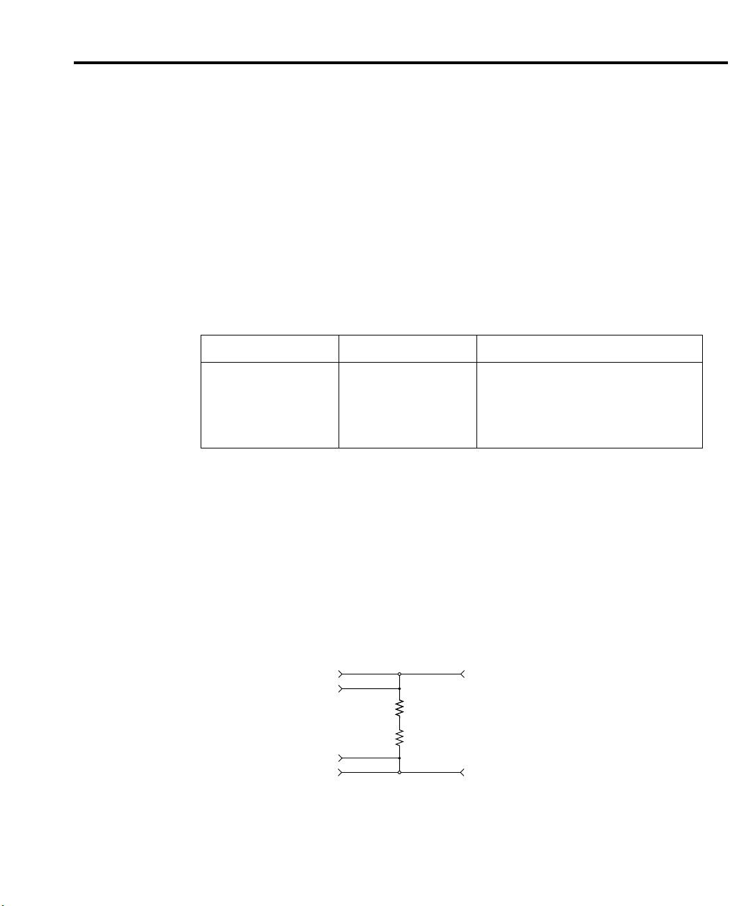
Resistor construction
4Ω resistor construction
The 4Ω resistor should be constructed by connecting the two 2Ω resistors listed in Table 1-1
in series. Make test and measurement connections across the combined series equivalent resistance. Figure 1-1 shows resistor construction and connections.
gure 1-
Ω
resistor construction
and connections
2304A Source +
2304A Sense +
2304A Sense 2304A Source -
DMM Input HI
2Ω 100W
2Ω 100W
DMM Input LO
Page 14
1-4 Performance Verification
Fi
2
4
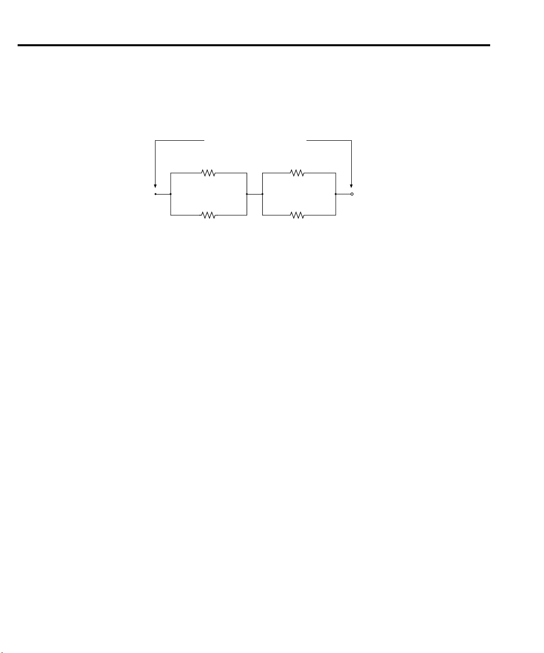
4kΩ resistor construction
The 4kΩ resistor should be constructed from four 4kΩ resistors in a series-parallel
configuration, shown in Figure 1-2. Again, make test and measurement connections across the
combined equivalent series-parallel resistance.
gure 1-
kΩ resistor construction
Resistor characterization
The 4Ω and 4kΩ resistors should be characterized using the 4-wire ohms function of the
DMM recommended in Table 1-1 to measure the resistance values. Use the measured resistance
values to calculate the actual currents during the test procedures.
Verification limits
The verification limits stated in the following paragraphs have been calculated using only the
Model 2304A accuracy specifications, and they do not include test equipment uncertainty. If a
particular measurement falls outside the allowable range, recalculate new limits based both on
Model 2304A specifications and corresponding test equipment specifications.
Test/Measurement Terminals
4kΩ
R
1
4kΩ
R
2
R1 - R4 = Keithley R-263-4k
4kΩ
R
4kΩ
R
3
4
Example limits calculation
As an example of how verification limits are calculated, assume you are testing the power
supply using a 10V output value. Using the Model 2304A voltage output accuracy specification
of ±(0.05% of output + 10mV offset), the calculated output limits are:
Output limits = 10V ±[(10V
Output limits = 10V ±(0.005 + 0.01%)
Output limits = 10V ±0.015V
Output limits = 9.985V to 10.015V
×
0.05%) + 10mV]
Page 15

Performance Verification 1-5
Performing the verification test procedures
Test summary
• DC voltage output accuracy
• DC voltage readback accuracy
• DC current output accuracy
• DC current readback accuracy
• Digital voltmeter input accuracy
If the Model 2304A is not within specifications and not under warranty, see the calibration
procedures in Section 2 for information on calibrating the unit.
Test considerations
When performing the verification procedures:
• Make sure that the test equipment is properly warmed up and connected to the correct
Model 2304A terminals on the rear panel. Also, be sure the test equipment is set up for
the proper function and range.
• Do not connect test equipment to the Model 2304A through a scanner, multiplexer, or
other switching equipment.
• Be sure that the power supply output is turned on before making measurements.
• Allow the power supply output signal to settle before making a measurement.
Setting output values
When performing the verification procedures, you must set the output voltage and current to
specific values.
Use the following general procedure to set output values:
1. Using the DISPLAY key, make sure the unit is in the ACTUAL display mode.
2. Press SET. The LSD (least-significant digit) in the voltage display area will blink, indicating that the unit is in the output setting mode.
3. Use the edit (arrow) keys to adjust the voltage value, then press SET. The LSD for the
current value will then blink.
4. Use the edit keys to adjust the current value and press SET. The display will return to the
readback mode (no blinking digits).
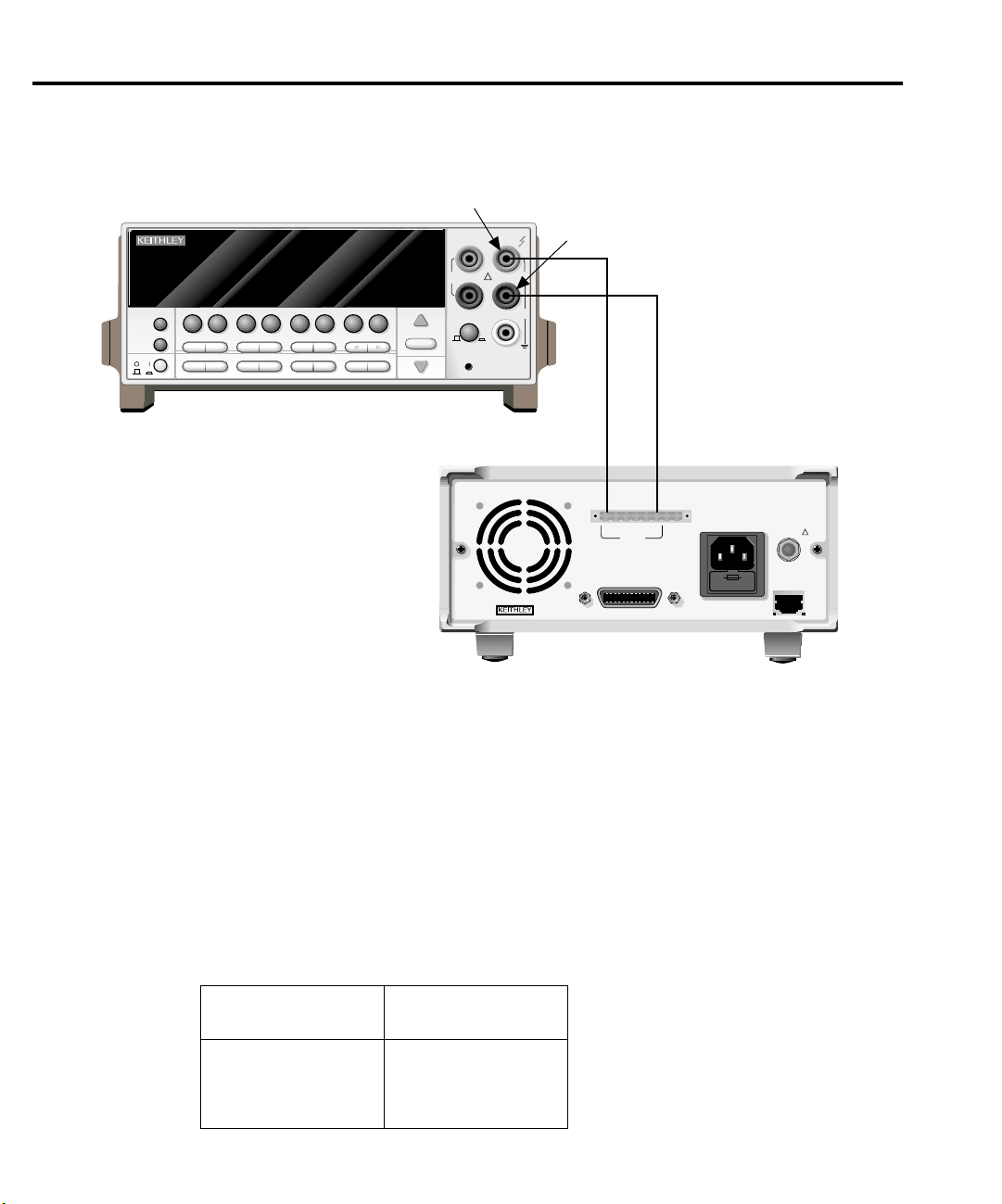
Output voltage accuracy
Follow the steps below to verify that Model 2304A output voltage accuracy is within specified limits. This test involves setting the output voltage to specific values and measuring the voltages with a precision digital multimeter.
1. With the power off, connect the digital multimeter to the Model 2304A OUTPUT
SOURCE terminals, as shown in Figure 1-3. Be sure to observe proper polarity
(SOURCE + to INPUT HI; SOURCE - to INPUT LO).
Page 16
1-6 Performance Verification
WARNING:NO INTERNAL OPERATOR SERVICABLE PARTS,SERVICE BY QUALIFIED PERSONNEL ONLY.
WARNING:NO INTERNAL OPERATOR SERVICABLE PARTS,SERVICE BY QUALIFIED PERSONNEL ONLY.
CAUTION:FOR CONTINUED PROTECTION AGAINST FIRE HAZARD,REPLACE FUSE WITH SAME TYPE AND RATING.
CAUTION:FOR CONTINUED PROTECTION AGAINST FIRE HAZARD,REPLACE FUSE WITH SAME TYPE AND RATING.
Fi
3
C
gure 1-
onnections for voltage
verification tests
PREV
DISPLAY
POWER
DCV ACV DCI ACI Ω2 Ω4
NEXT
REL TRIG
STORE RECALL
INFO LOCAL EXIT ENTER
CHAN SCAN
Model 2001 DMM
FILTER MATH
CONFIG MENU
2001 MULTIMETER
FREQ TEMP
RANGE
AUTO
RANGE
Input HI
SENSE
Ω 4 WIRE
350V
PEAK
INPUTS
FR
FRONT/REAR
CAL
INPUT
HI
!
LO
2A 250V
AMPS
Input LO
1100V
PEAK
500V
PEAK
Source + Source -
DVM IN
LINE FUSE
SLOWBLOW
2.5A, 250V
LINE RATING
100-240VAC
50, 60 HZ
185VA MAX
+
RELAY
CONTROL
15VDC MAX
REMOTE
DISPLAY
OPTION
!
MADE IN
U.S.A.
ISOLATION FROM EARTH:
22 VOLTS MAX.
____
+++
SOURCE
SOURCE
SENSE
OUTPUT
0-20V, 0-5A
IEEE-488
(CHANGE IEEE ADDRESS
WITH FRONT PANEL MENU)
Model 2304A
2. Select the multimeter DC volts measuring function and enable auto-ranging.
3. Make sure the Model 2304A output is turned on.
4. Verify output voltage accuracy for each of the voltages listed in Table 1-2. For each test
point:
• Use the SET key to adjust the Model 2304A output voltage to the indicated value.
When setting the voltage, set the compliance current to 5A.
• Allow the reading to settle.
• Verify that the multimeter reading is within the limits given in Table 1-2.
5. Repeat the procedure for negative output voltages with the same magnitude as those
listed in Table 1-2.
Table 1-2
Output voltage accuracy limits
Model 2304A output
voltage setting
5.00V
10.00V
15.00V
20.00V
Output voltage limits
(1 year, 18˚ to 28˚C)
04.9875 to 5.0125V
09.9850 to 10.015V
14.9825 to 15.0175V
19.9800 to 20.020V
Page 17

Voltage readback accuracy
Follow the steps below to verify that Model 2304A voltage readback accuracy is within
specified limits. The test involves setting the source voltage to specific values, as measured by a
digital multimeter, and then verifying that the Model 2304A voltage readback readings are
within required limits.
1. With the power off, connect the digital multimeter to the Model 2304A OUTPUT
SOURCE terminals, as shown in Figure 1-3. Be sure to observe proper polarity
(SOURCE + to INPUT HI; SOURCE - to INPUT LO).
2. Select the multimeter DC volts measuring function and enable auto-ranging.
3. Make sure actual voltage readings are being displayed (use DISPLAY) and turn on the
Model 2304A output.
4. Verify voltage readback accuracy for each of the voltages listed in Table 1-3. For each
test point:
• Use the SET key to adjust the Model 2304A output voltage to the indicated value as
measured by the digital multimeter. Note that it may not be possible to set the voltage
source precisely to the specified value. Use the closest possible setting and modify
reading limits accordingly. When setting the voltage, set the compliance current
to 5A.
• Allow the reading to settle.
• Verify that the actual voltage reading on the Model 2304A display is within the limits
given in the table.
5. Repeat the procedure for negative source voltages with the same magnitudes as those
listed in Table 1-3.
Performance Verification 1-7
Table 1-3
Voltage readback accuracy limits
Model 2304A output
voltage setting*
5.00V
10.00V
15.00V
19.00V
*As measured by digital multimeter. See procedure.
Voltage readback limits
(1 year, 18˚ to 28˚C)
04.988 to 5.012V
09.985 to 10.015V
14.983 to 15.017V
18.981 to 19.019V
Page 18
1-8 Performance Verification
WARNING:NO INTERNAL OPERATOR SERVICABLE PARTS,SERVICE BY QUALIFIED PERSONNEL ONLY.
WARNING:NO INTERNAL OPERATOR SERVICABLE PARTS,SERVICE BY QUALIFIED PERSONNEL ONLY.
CAUTION:FOR CONTINUED PROTECTION AGAINST FIRE HAZARD,REPLACE FUSE WITH SAME TYPE AND RATING.
CAUTION:FOR CONTINUED PROTECTION AGAINST FIRE HAZARD,REPLACE FUSE WITH SAME TYPE AND RATING.
Fi
4
C
Compliance current accuracy
Follow the steps below to verify that Model 2304A compliance current accuracy is within
specified limits. The test involves setting the compliance current to specific values and determining the actual current by measuring the voltages across a characterized 4
sion digital multimeter.
Ω
resistor with a preci-
1. With the power off, connect the digital multimeter and 4
OUTPUT SOURCE terminals, as shown in Figure 1-4. Be sure to observe proper polarity (SOURCE + to INPUT HI; SOURCE - to INPUT LO). Also be sure to use 4-wire
connections from the Model 2304A to the resistor terminals.
2. Select the multimeter DC volts measuring function and enable auto-ranging.
3. Turn on the Model 2304A output.
gure 1-
onnections for output current
and 5A range verification tests
PREV
DCV ACV DCI ACI Ω2 Ω4
DISPLAY
NEXT
REL TRIG
POWER
STORE RECALL
INFO LOCAL EXIT ENTER
CHAN SCAN
Model 2001 DMM
Note: Use 4-wire connections
to resistor terminals.
FILTER MATH
CONFIG MENU
2001 MULTIMETER
FREQ TEMP
RANGE
AUTO
RANGE
Input HI
SENSE
Ω 4 WIRE
350V
PEAK
INPUTS
FR
FRONT/REAR
CAL
Ω
resistor to the Model 2304A
INPUT
HI
!
LO
2A 250V
AMPS
Input LO
1100V
PEAK
500V
PEAK
4kΩ Resistor
Sense + Sense -
Source + Source -
DVM IN
LINE FUSE
SLOWBLOW
2.5A, 250V
LINE RATING
100-240VAC
50, 60 HZ
185VA MAX
+
RELAY
CONTROL
15VDC MAX
REMOTE
DISPLAY
OPTION
!
MADE IN
U.S.A.
ISOLATION FROM EARTH:
22 VOLTS MAX.
____
+++
SOURCE SENSE
SOURCE
OUTPUT
0-20V, 0-5A
IEEE-488
(CHANGE IEEE ADDRESS
WITH FRONT PANEL MENU)
Model 2304A
Page 19

Performance Verification 1-9
4. Verify compliance current accuracy for the currents listed in Table 1-4. For each test
point:
• Use the SET key to adjust the Model 2304A output voltage to 20V and set the com-
pliance current to the value being tested.
• Note and record the digital multimeter voltage reading.
Ω
• Calculate the current from the voltage reading and actual 4
• Verify that the current is within the limits given in Table 1-4.
Table 1-4
Compliance current accuracy limits
resistor value (I=V/R).
Model 2304A compliance
current setting
1.000A
2.000A
3.000A
4.000A
5.000A
Compliance current limits
(1 year, 18˚ to 28˚C)
0.993 to 1.007A
1.992 to 2.008A
2.990 to 3.010A
3.989 to 4.011A
4.987 to 5.013A
Current readback accuracy
Follow the steps below to verify that Model 2304A current readback accuracy is within
specified limits. The test involves setting the output current to specific values as measured with
a resistor and precision digital multimeter.
5A range readback accuracy
1. With the power off, connect the digital multimeter and 4Ω resistor to the Model 2304A
OUTPUT SOURCE terminals, as shown in Figure 1-4. Be sure to observe proper polarity (SOURCE + to INPUT HI; SOURCE - to INPUT LO). Also, be sure to use 4-wire
connections to the resistor terminals.
2. Select the multimeter DC volts measuring function and enable auto-ranging.
3. Using the Model 2304A MENU key, select the 5A readback range. Also make sure actual current readings are displayed (use DISPLAY).
4. Turn on the Model 2304A output.
Page 20

1-10 Performance Verification
5. Verify 5A range current readback accuracy for the currents listed in Table 1-5. For each
test point:
• By changing the output voltage with the SET key, adjust the current to the correct
value, as determined from the multimeter voltage reading and characterized resistance value. When setting the voltage, be sure to set the compliance current to 5A.
• Note that it may not be possible to set the output current to the exact value. In that
case, set the current to the closest possible value and modify reading limits
accordingly.
• Allow the reading to settle.
• Verify that the actual current reading on the Model 2304A display is within the limits
given in Table 1-5.
Table 1-5
5A range current readback accuracy limits
Nominal output
voltage
4V
8V
12V
16V
19V
*As determined from digital multimeter and 4Ω resistor. See procedure.
Model 2304A output
current*
1.000A
2.000A
3.000A
4.000A
4.750A
5mA range readback accuracy
1. With the power off, connect the digital multimeter and 4kΩ resistor to the Model 2304A
OUTPUT SOURCE terminals, as shown in Figure 1-5. Be sure to observe proper
polarity and connections (4k
SOURCE - to DMM INPUT LO).
2. Select the multimeter DC volts measuring function and enable auto-ranging.
3. Using the Model 2304A MENU key, select the 5mA readback range. Also display actual
current readings with the DISPLAY key.
4. Turn on the Model 2304A output.
5. Verify 5mA range current readback accuracy for the currents listed in Table 1-6. For each
test point:
• By changing the output voltage with the SET key, adjust the Model 2304A output cur-
rent to the correct value, as determined from the digital multimeter voltage reading
and 4k
Ω
resistance value. Note that it may not be possible to set the output current to
the exact value. In that case, set the current to the closest possible value and modify
reading limits accordingly.
• Allow the reading to settle.
• Verify that the actual current reading on the Model 2304A display is within the limits
given in Table 1-6.
Current readback limits
(1 year, 18˚ to 28˚C)
0.9970 to 1.0030A
1.9950 to 2.0050A
2.9930 to 3.0070A
3.9910 to 4.0090A
4.7395 to 4.7605A
Ω
resistor between SOURCE + and DMM INPUT HI;
Page 21

WARNING:NO INTERNAL OPERATOR SERVICABLE PARTS,SERVICE BY QUALIFIED PERSONNEL ONLY.
WARNING:NO INTERNAL OPERATOR SERVICABLE PARTS,SERVICE BY QUALIFIED PERSONNEL ONLY.
CAUTION:FOR CONTINUED PROTECTION AGAINST FIRE HAZARD,REPLACE FUSE WITH SAME TYPE AND RATING.
CAUTION:FOR CONTINUED PROTECTION AGAINST FIRE HAZARD,REPLACE FUSE WITH SAME TYPE AND RATING.
Fi
gure 1-
5
R
5
esistor connections for
mA range verification tests
PREV
DISPLAY
POWER
DCV ACV DCI ACI Ω2 Ω4
NEXT
REL TRIG
STORE RECALL
INFO LOCAL EXIT ENTER
CHAN SCAN
FILTER MATH
CONFIG MENU
2001 MULTIMETER
FREQ TEMP
RANGE
AUTO
RANGE
Input HI
SENSE
Ω 4 WIRE
350V
PEAK
INPUTS
FR
FRONT/REAR
CAL
Performance Verification 1-11
INPUT
HI
!
LO
2A 250V
AMPS
Input LO
1100V
PEAK
500V
PEAK
4kΩ Resistor
Model 2001 DMM
Sense + Sense -
Source + Source -
DVM IN
LINE FUSE
SLOWBLOW
2.5A, 250V
LINE RATING
100-240VAC
50, 60 HZ
185VA MAX
+
RELAY
CONTROL
15VDC MAX
REMOTE
DISPLAY
OPTION
!
ISOLATION FROM EARTH:
22 VOLTS MAX.
____
+++
SOURCE SENSE
SOURCE
OUTPUT
0-20V, 0-5A
IEEE-488
(CHANGE IEEE ADDRESS
WITH FRONT PANEL MENU)
Note: Use 4-wire connections
to resistor terminals.
MADE IN
U.S.A.
Model 2304A
Table 1-6
5mA range current readback accuracy limits
Nominal output
voltage
4V
8V
12V
16V
19V
*As determined from digital multimeter voltage readng and 4kΩ resistance value.
See procedure.
Model 2304A
output current*
1.0000mA
2.0000mA
3.0000mA
4.0000mA
4.7500mA
Current readback limits
(1 year, 18˚ to 28˚C)
0.9970 to 1.0030mA
1.9950 to 2.0050mA
2.9930 to 3.0070mA
3.9910 to 4.0090mA
4.7395 to 4.7605mA
Page 22

WARNING:NO INTERNAL OPERATOR SERVICABLE PARTS,SERVICE BY QUALIFIED PERSONNEL ONLY.
WARNING:NO INTERNAL OPERATOR SERVICABLE PARTS,SERVICE BY QUALIFIED PERSONNEL ONLY.
CAUTION:FOR CONTINUED PROTECTION AGAINST FIRE HAZARD,REPLACE FUSE WITH SAME TYPE AND RATING.
CAUTION:FOR CONTINUED PROTECTION AGAINST FIRE HAZARD,REPLACE FUSE WITH SAME TYPE AND RATING.
Fi
6
C
1-12 Performance Verification
Digital voltmeter input accuracy
Follow the steps below to verify that Model 2304A digital voltmeter input accuracy is within
specified limits. The test involves setting the voltage applied to the DVM input to accurate values
and then verifying that the Model 2304A digital voltmeter input readings are within required limits.
1. With the power off, connect the Model 2304A DVM IN terminals to OUTPUT SOURCE
terminals and the digital multimeter, as shown in Figure 1-6. Be sure to observe proper
polarity (DVM IN + SOURCE + and DMM INPUT HI; DVM IN - to SOURCE - and
DMM INPUT LO).
2. Select the DMM DC volts measuring function and enable auto-ranging.
3. Using the DISPLAY key, enable the Model 2304A DVM input.
4. Turn on the Model 2304A source output.
gure 1-
onnections for DVM
accuracy verification
Input HI
SENSE
INPUT
Ω 4 WIRE
HI
350V
PEAK
2001 MULTIMETER
PREV
DCV ACV DCI ACI Ω2 Ω4
DISPLAY
NEXT
REL TRIG
POWER
STORE RECALL
INFO LOCAL EXIT ENTER
CHAN SCAN
FREQ TEMP
FILTER MATH
CONFIG MENU
RANGE
AUTO
RANGE
INPUTS
FR
FRONT/REAR
Model 2001 DMM
1100V
!
PEAK
LO
500V
PEAK
2A 250V
AMPS
CAL
Source +
Source -
Input LO
DVM IN -
DVM IN +
MADE IN
DVM IN
LINE FUSE
SLOWBLOW
2.5A, 250V
LINE RATING
100-240VAC
50, 60 HZ
185VA MAX
+
RELAY
CONTROL
15VDC MAX
REMOTE
DISPLAY
OPTION
!
ISOLATION FROM EARTH:
22 VOLTS MAX.
____
+++
SOURCE SENSE
SOURCE
OUTPUT
0-20V, 0-5A
IEEE-488
(CHANGE IEEE ADDRESS
WITH FRONT PANEL MENU)
U.S.A.
Model 2304A
Page 23

Performance Verification 1-13
5. Verify digital voltmeter input accuracy for each of the voltages listed in Table 1-7. For
each test point:
• Use the SET key to adjust the voltage to the indicated value as measured by the digital
multimeter.
• Allow the reading to settle.
• Verify that the voltage reading on the Model 2304A display is within the limits given
in Table 1-7.
Table 1-7
Digital voltmeter input accuracy limits
Model 2304A voltage
output setting*
+19.00V
-3.00V
*As measured by digital multimeter. See procedure.
Digital voltmeter input reading
limits (1 year, 18˚ to 28˚C)
+18.981 to +19.019V
-3.019 to -2.981V
Page 24

2
Calibration
Page 25

2-2 Calibration
Introduction
Use the procedures in this section to calibrate the Model 2304A. These procedures require
accurate test equipment to measure precise DC voltages and currents. Calibration can be performed either from the front panel or by sending SCPI calibration commands over the IEEE-488
bus with the aid of a computer.
WARNING The information in this section is intended for qualified service personnel
only. Do not attempt these procedures unless you are qualified to do so.
Environmental conditions
Temperature and relative humidity
Conduct the calibration procedures at an ambient temperature of 18˚ to 28˚C (65˚ to 82˚F)
with a relative humidity of less than 70% unless otherwise noted.
Warm-up period
Allow the Model 2304A to warm up for at least one hour before performing calibration.
If the instrument has been subjected to extreme temperatures (those outside the ranges stated
above), allow additional time for the instrument’s internal temperature to stabilize. Typically,
allow one extra hour to stabilize a unit that is 10˚C (18˚F) outside the specified temperature
range.
Also, allow the test equipment to warm up for the minimum time specified by the
manufacturer.
Line power
The Model 2304A requires a line voltage of 100 to 240V at line frequency of 50 to 60Hz. The
instrument must be calibrated while operating from a line voltage within this range.
Page 26

Calibration considerations
When performing the calibration procedures:
• Make sure the test equipment is properly warmed up and connected to the appropriate
Model 2304A terminals.
• Always allow the source signal to settle before calibrating each point.
• Do not connect test equipment to the Model 2304A through a scanner or other switching
equipment.
• Calibration must be performed in the sequence outlined in this manual or an error will
occur.
• If an error occurs during calibration, the Model 2304A will generate an appropriate error
message. See Appendix B for more information.
WARNING The maximum common-mode voltage (voltage between LO and chassis
ground) is 22VDC. Exceeding this value may cause a breakdown in insulation, creating a shock hazard.
Calibration cycle
Calibration 2-3
Perform calibration at least once a year to ensure the unit meets or exceeds its specifications.
Recommended calibration equipment
Table 2-1 lists the recommended equipment for the calibration procedures. You can use alternate equipment as long as that equipment has specifications at least four times better than the
corresponding Model 2304A specifications.
Table 2-1
Recommended calibration equipment
Description Manufacturer/Model Specifications
Digital Multimeter
Precision Resistors (2)
Precision Resistors (4)
***Full-range, 90-day, 23˚C ±5˚C accuracy specifications of ranges required for various measurement points.
***Connect two 2Ω resistors in series to make single 4Ω resistor. Characterize resistor using 20Ω range of
DMM before use.
***Connect four 4kΩ resistors in series-parallel to make single 4kΩ resistor. Characterize resistor using 20kΩ
range of DMM before use.
Keithley 2001
Isotec RUG-Z-2R002
Dale PTF-56 .1%T13
DC Voltage* 20V: ±22ppm
Resistance* 20Ω: ±59ppm
2Ω, 0.1%, 100W**
4kΩ, 0.1%, 0.125W***
20kΩ: ±36ppm
Page 27

2-4 Calibration
Fi
1
4
Fi
2
4
Resistor construction
gure 2-
Ω
resistor construction
and connections
gure 2-
kΩ resistor
construction
4Ω resistor construction
The 4Ω resistor should be constructed by connecting the two 2Ω resistors listed in Table 2-1
in series. Make test and measurement connections across the combined series equivalent resistance. See Figure 2-1 for resistor construction and connections.
2304A Source +
2304A Sense +
2Ω 100W
2Ω 100W
2304A Sense -
2304A Source -
DMM Input HI
DMM Input LO
4kΩ resistor construction
The 4kΩ resistor should be constructed from four 4kΩ resistors in a series-parallel configu-
ration, as shown in Figure 2-2. Again, make test and measurement connections across the combined equivalent series-parallel resistance.
Test/Measurement Terminals
4kΩ
R
1
4kΩ
R
3
4kΩ
R
2
R1 - R4 = Keithley R-263-4k
4kΩ
R
4
Resistor characterization
The 4Ω and 4kΩ resistors should be characterized using the 4-wire ohms function of the
DMM recommended in Table 2-1 to measure the resistance values. Use the measured resistance
values to calculate the actual currents during the calibration procedure.
Page 28

Front panel calibration
NOTE Calibration must be performed in the following sequence or an error will occur. To
abort calibration and revert to previous calibration constants at any time during the
procedure, press the MENU key.
Step 1: Prepare the Model 2304A for calibration
1. Turn on the Model 2304A and the digital multimeter; allow them to warm up for at least
one hour before performing calibration.
2. Press the MENU key, choose CALIBRATE UNIT, and press ENTER. The instrument
will display the date last calibrated:
CALIBRATE UNIT
LAST ON 02/01/97
3. Press the up arrow key. The instrument will display the number of times it was
calibrated:
CALIBRATE UNIT
TIMES = 01
4. Press the up arrow key. The unit will prompt you to run calibration:
CALIBRATE UNIT
RUN
5. Press ENTER. The unit will prompt for the calibration code:
CALIBRATE UNIT
Cal Code KI002304
6. Using the edit keys, set the display to the current calibration code and press ENTER (default: KI002304). The unit will prompt you as to whether or not to change the code:
CALIBRATE UNIT
Change Code NO
7. Be sure NO is selected (use the up or down arrow keys), press ENTER, and then follow
the steps below to calibrate the unit. (See Changing the calibration code at the end of
this section to change the code.)
Calibration 2-5
Page 29

2-6 Calibration
WARNING:NO INTERNAL OPERATOR SERVICABLE PARTS,SERVICE BY QUALIFIED PERSONNEL ONLY.
WARNING:NO INTERNAL OPERATOR SERVICABLE PARTS,SERVICE BY QUALIFIED PERSONNEL ONLY.
CAUTION:FOR CONTINUED PROTECTION AGAINST FIRE HAZARD,REPLACE FUSE WITH SAME TYPE AND RATING.
CAUTION:FOR CONTINUED PROTECTION AGAINST FIRE HAZARD,REPLACE FUSE WITH SAME TYPE AND RATING.
Fi
3
C
Step 2: Perform calibration steps
NOTE The unit will display the most recently calibrated values. Factory defaults are shown
gure 2-
onnections for voltage
calibration
PREV
DCV ACV DCI ACI Ω2 Ω4
DISPLAY
NEXT
POWER
REL TRIG
INFO LOCAL EXIT ENTER
in this manual.
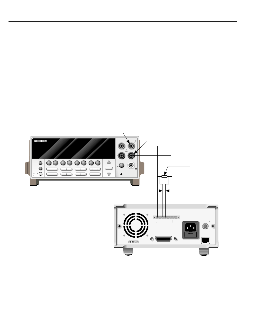
1. Connect both the OUTPUT SOURCE and DVM IN terminals to the digital multimeter,
as shown in Figure 2-3. (Connect SOURCE + and DVM IN + to DMM INPUT HI; connect SOURCE - and DVM IN - to DMM INPUT LO.)
2. At this point, the Model 2304A will prompt you to set the full-scale output voltage:
FULL SCALE VOLTS
SET 19.0000 V
STORE RECALL
CHAN SCAN
FILTER MATH
CONFIG MENU
2001 MULTIMETER
FREQ TEMP
RANGE
AUTO
RANGE
Input HI
SENSE
Ω 4 WIRE
350V
PEAK
INPUTS
FR
FRONT/REAR
CAL
INPUT
HI
!
LO
2A 250V
AMPS
Input LO
1100V
PEAK
500V
PEAK
Source -
DVM IN +
DVM IN -
Model 2001 DMM
Source +
DVM IN
LINE FUSE
SLOWBLOW
2.5A, 250V
LINE RATING
100-240VAC
50, 60 HZ
185VA MAX
+
RELAY
CONTROL
15VDC MAX
REMOTE
DISPLAY
OPTION
!
MADE IN
ISOLATION FROM EARTH:
22 VOLTS MAX.
____
+++
SOURCE SENSE
SOURCE
OUTPUT
0-20V, 0-5A
IEEE-488
(CHANGE IEEE ADDRESS
WITH FRONT PANEL MENU)
U.S.A.
Model 2304A
Page 30

Calibration 2-7
3. Use the edit keys to set the voltage to 19.0000V and press ENTER.
NOTE At this point, the source output is turned on and will remain on until calibration is
completed or aborted with the MENU key.
4. The unit will prompt you for the DMM reading, which will be used to calibrate the fullscale output voltage:
FULL SCALE VOLTS
READ1 19.0000 V
5. Using the edit keys, adjust the Model 2304A voltage display to agree with the DMM
voltage reading and press ENTER. The unit will prompt for another DMM reading,
which will be used to calibrate the full-scale measurement function:
FULL SCALE VOLTS
READ2 19.0000 V
6. Using the edit keys, adjust the display to agree with the new DMM voltage reading and
press ENTER. The unit will then prompt for DVM full-scale calibration:
FULL SCALE DVM
ALL READY TO DO?
7. Press ENTER to complete DVM full-scale calibration.
Page 31

WARNING:NO INTERNAL OPERATOR SERVICABLE PARTS,SERVICE BY QUALIFIED PERSONNEL ONLY.
WARNING:NO INTERNAL OPERATOR SERVICABLE PARTS,SERVICE BY QUALIFIED PERSONNEL ONLY.
CAUTION:FOR CONTINUED PROTECTION AGAINST FIRE HAZARD,REPLACE FUSE WITH SAME TYPE AND RATING.
CAUTION:FOR CONTINUED PROTECTION AGAINST FIRE HAZARD,REPLACE FUSE WITH SAME TYPE AND RATING.
Fi
4
C
2-8 Calibration
gure 2-
onnections for 5A
current calibration
PREV
DISPLAY
NEXT
POWER
DCV ACV DCI ACI Ω2 Ω4
REL TRIG
INFO LOCAL EXIT ENTER
8. Connect the digital multimeter volts input and 4Ω resistor to the Model 2304A OUTPUT
SOURCE terminals, as shown in Figure 2-4. Be sure to observe proper polarity
(SOURCE + to DMM INPUT HI; SOURCE - to INPUT LO).
9. Be sure the digital multimeter DC volts function and auto-ranging are still selected.
10. At this point, the unit will prompt for 5A full-scale calibration output:
SOURCE 5 AMPS
SET 1.90000 A
11. Using the edit keys, adjust the set value to 1.9000A and press ENTER. The unit will
prompt you for the DMM reading, which calibrates the 5A current limit:
SOURCE 5 AMPS
READ1 1.90000 A
12. Note the DMM voltage reading and calculate the current from that reading and the actual
4Ω resistance value (I=V/R). Adjust the Model 2304A current display value to agree
with the calculated current value, and press ENTER.
Input HI
Input LO
1100V
PEAK
500V
PEAK
4kΩ Resistor
STORE RECALL
CHAN SCAN
FILTER MATH
CONFIG MENU
2001 MULTIMETER
FREQ TEMP
RANGE
AUTO
RANGE
SENSE
Ω 4 WIRE
350V
PEAK
INPUTS
FR
FRONT/REAR
CAL
INPUT
HI
!
LO
2A 250V
AMPS
Model 2001 DMM
Note: Use 4-wire connections
to resistor terminals.
Sense + Sense -
Source + Source -
ISOLATION FROM EARTH:
22 VOLTS MAX.
____
MADE IN
U.S.A.
+++
SOURCE SENSE
IEEE-488
(CHANGE IEEE ADDRESS
WITH FRONT PANEL MENU)
OUTPUT
0-20V, 0-5A
SOURCE
DVM IN
+
Model 2304A
LINE FUSE
SLOWBLOW
2.5A, 250V
LINE RATING
100-240VAC
50, 60 HZ
185VA MAX
RELAY
CONTROL
15VDC MAX
REMOTE
DISPLAY
OPTION
!
Page 32

WARNING:NO INTERNAL OPERATOR SERVICABLE PARTS,SERVICE BY QUALIFIED PERSONNEL ONLY.
WARNING:NO INTERNAL OPERATOR SERVICABLE PARTS,SERVICE BY QUALIFIED PERSONNEL ONLY.
CAUTION:FOR CONTINUED PROTECTION AGAINST FIRE HAZARD,REPLACE FUSE WITH SAME TYPE AND RATING.
CAUTION:FOR CONTINUED PROTECTION AGAINST FIRE HAZARD,REPLACE FUSE WITH SAME TYPE AND RATING.
Fi
5
C
Calibration 2-9
13. The Model 2304A will then prompt for another DMM reading, which is used for 5A
measurement calibration:
SOURCE 5 AMPS
READ2 1.90000 A
14. Again, calculate the current from the new DMM reading and 4Ω resistor value. Adjust
the Model 2304A current display reading to agree with the new current and press
ENTER.
15. Disconnect the 4Ω resistor and connect the 4kΩ resistor in its place (see Figure 2-5).
16. Make sure the DMM DC volts function and auto-ranging are still selected.
17. At this point, the unit will prompt to output approximately 5mA for 5mA range full-scale
calibration:
SOURCE 5 mA
ALL READY TO DO?
gure 2-
onnections for 5mA
current calibration
Input HI
SENSE
INPUT
Ω 4 WIRE
HI
350V
!
PEAK
2001 MULTIMETER
PREV
DCV ACV DCI ACI Ω2 Ω4
DISPLAY
NEXT
REL TRIG
POWER
STORE RECALL
INFO LOCAL EXIT ENTER
CHAN SCAN
FILTER MATH
CONFIG MENU
FREQ TEMP
RANGE
AUTO
RANGE
LO
INPUTS
FR
FRONT/REAR
CAL
2A 250V
AMPS
Input LO
1100V
PEAK
500V
PEAK
4kΩ Resistor
Note: Use 4-wire connections
to resistor terminals.
Model 2001 DMM
Sense + Sense -
Source + Source -
ISOLATION FROM EARTH:
22 VOLTS MAX.
____
MADE IN
U.S.A.
+++
SOURCE SENSE
IEEE-488
(CHANGE IEEE ADDRESS
WITH FRONT PANEL MENU)
OUTPUT
0-20V, 0-5A
SOURCE
DVM IN
+
Model 2304A
LINE FUSE
SLOWBLOW
2.5A, 250V
LINE RATING
100-240VAC
50, 60 HZ
185VA MAX
RELAY
CONTROL
15VDC MAX
REMOTE
DISPLAY
OPTION
!
Page 33

2-10 Calibration
18. Press ENTER to output approximately 5mA. The unit will prompt you for the DMM
reading:
SOURCE 5 mA
READ1 4.50000 mA
19. Note the DMM voltage reading and calculate the current from that voltage reading and
actual 4kΩ resistance value. Adjust the Model 2304A current display value to agree with
that value, and press ENTER.
Step 3: Enter calibration dates and save calibration
1. After completing all calibration steps, the unit will prompt you to save calibration:
CALIBRATE UNIT
Save Cal Data YES
2. To save new calibration constants, select YES with the up arrow key and press ENTER.
If you wish to exit calibration without saving new calibration constants, select NO and
press ENTER. The unit will then revert to prior calibration constants.
3. The unit will then prompt you to enter the calibration date:
CALIBRATE UNIT
Cal Date 02/01/97
4. Using the edit keys, set the calibration date to today’s date and press ENTER. The unit
will display the following:
CALIBRATE UNIT
EXITING CAL
5. Press ENTER to complete the calibration procedure and return to the menu display.
Calibration is now complete. Refer to Table 2-2 for a summary of front panel calibration.
Table 2-2
Front panel calibration summary
Step* Description Nominal calibration signal** Test connections
Output 19V
0
Full-scale output voltage
1
Full-scale measure
2
Full-scale DVM
3
5A range output current
4
5A current limit
5
5A measure
6
5mA range output current
7
5mA measure
8
**Step numbers correspond to :CAL:PROT:STEP command numbers. See Table 2-3.
**Factory default display values. Unit will display most recently used value.
19V
19V
19V
19V
1.9A
1.9A
1.9A
4.5mA
4.5mA
Figure 2-3
Figure 2-3
Figure 2-3
Figure 2-3
Figure 2-4
Figure 2-4
Figure 2-4
Figure 2-5
Figure 2-5
Page 34

Remote calibration
Use the following procedure to perform remote calibration by sending SCPI commands over
the IEEE-488 bus. The remote commands and appropriate parameters are separately summarized for each step.
Remote calibration commands
Table 2-3 summarizes remote calibration commands. For a more complete description of
these commands, refer to Appendix B.
Table 2-3
Remote calibration command summary
Command Description
Calibration 2-11
:CALibration
:PROTected
:CODE ‘<code>’
:COUNt?
:DATE <yyyy>,<mm>,<dd>
:DATE?
:INIT
:LOCK
:SAVE
:STEP0 <nrf>
:STEP1 <nrf>
:STEP2 <nrf>
:STEP3
:STEP4 <nrf>
:STEP5 <nrf>
:STEP6 <nrf>
:STEP7
:STEP8 <nrf>
* Calibration data will not be saved if:
1. Calibration was not unlocked with :CODE command.
2. Invalid data exists. (For example, cal step failed or was aborted.)
3. Incomplete number of cal steps were performed.
4. Calibration was not performed in the proper sequence.
Calibration subsystem.
Cal commands protected by code.
Unlock cal; changes code if cal is already unlocked.
(Default password: KI002304.)
Query number of times 2304A has been calibrated.
Program calibration year, month, day.
Query calibration year, month, day.
Initiate calibration (must be sent before other cal steps).
Lock out calibration. (Abort if calibration is
incomplete.)
Save calibration data to EEPROM.*
Output full-scale voltage (19V).
Calibrate output voltage setting using external DMM
reading.
Calibrate voltage measuring using external DMM
reading.
Perform DVM input full-scale (19V) cal.
Output current (1.9A) for 5A full-scale cal.
Calibrate output current limit using calculated current.
Calibrate 5A measurement range using calculated
current.
Output 5mA nominal current for 5mA range full-scale
cal.
Calibrate 5mA measurement range using calculated
current.
Page 35

2-12 Calibration
Remote calibration display
Remote calibration procedure
The unit will display the following while being calibrated over the bus.
CALIBRATING UNIT
FROM THE BUS R
NOTE Calibration steps must be performed in the following sequence or an error will occur.
You can abort the procedure and revert to previous calibration constants at any time
before :SAVE by sending the :CAL:PROT:LOCK command.
Step 1: Prepare the Model 2304A for calibration
1. Connect the Model 2304A to the controller IEEE-488 interface using a shielded interface cable.
2. Turn on the Model 2304A and the test equipment. Allow them to warm up for at least
one hour before performing calibration.
3. Make sure the IEEE-488 primary address of the Model 2304A is the same as the address
specified in the program you will be using to send commands. (Use the MENU key to
access the primary address.)
4. Send the following command with the correct code to unlock calibration:
:CAL:PROT:CODE ‘<code>’
For example, with the factory default code of KI002304, send:
CAL:PROT:CODE ‘KI002304’
5. Send the following command to initiate calibration:
:CAL:PROT:INIT
Step 2: Perform calibration steps
NOTE Allow the Model 2304A to complete each calibration step before going on to the next
one. See “Detecting calibration step completion” in Appendix B.
1. Connect both the OUTPUT SOURCE and DVM IN terminals to the digital multimeter,
as shown in Figure 2-3. (Connect SOURCE + and DVM IN + to DMM INPUT HI;
SOURCE - and DVM IN - to DMM INPUT LO.)
2. Send the following command to output 19V:
:CAL:PROT:STEP0 19
NOTE At this point, the source output is turned on and will remain on until calibration is
completed or aborted with the :CAL:PROT:LOCK command.
Page 36

Calibration 2-13
3. Note and record the DMM reading, and then send that reading as the parameter for the
following command:
:CAL:PROT:STEP1 <DMM_Reading>
For example, if the DMM reading is 19.012V, the command would be:
:CAL:PROT:STEP1 19.012
4. Note and record a new DMM reading, and then send that reading as the parameter for
the following command:
:CAL:PROT:STEP2 <DMM_Reading>
5. Send the following command for DVM full-scale calibration:
:CAL:PROT:STEP3
6. Connect the Model 2304A OUTPUT SOURCE terminals to the DMM volts input and
4Ω resistor, as shown in Figure 2-4. Be sure to observe proper polarity (SOURCE + to
INPUT HI; SOURCE - to INPUT LO).
7. Make sure the digital multimeter DC volts function and auto-ranging are still selected.
8. Send the following command to output 1.9A for 5A full-scale calibration:
:CAL:PROT:STEP4 1.9
9. Note and record the DMM voltage reading, and then calculate the current from that reading and 4Ω resistor value. Send the following command using that calculated current as
the parameter:
:CAL:PROT:STEP5 <Calculated_Current>
For example, with a current value of 1.894A, the command would appear as follows:
:CAL:PROT:STEP5 1.894
10. Note and record a new DMM voltage reading, and again calculate the current from the
voltage and resistance. Send the calculated current value as the parameter for the following command:
:CAL:PROT:STEP6 <Calculated_Current>
11. Connect the 4kΩ resistor in place of the 4Ω resistor (see Figure 2-5).
12. Make sure the DMM DC volts function and auto-range are still selected.
13. Send the following command to output approximately 5mA for 5mA full-scale
calibration:
:CAL:PROT:STEP7
14. Note and record the DMM voltage reading, and then calculate the current from the voltage reading and actual 4kΩ resistance value. Send that current value as the parameter for
the following command:
:CAL:PROT:STEP8 <Calculated_Current>
For example, with a current of 4.8mA, the command would be:
:CAL:PROT:STEP8 4.8E-3
Page 37

2-14 Calibration
Step 3: Program calibration date
Use the following commands to set the calibration date:
:CAL:PROT:DATE <yyyy>, <mm>, <dd>
Note that the year, month, and date must be separated by commas. The allowable range for
the year is from 1997 to 2096, the month is from 1 to 12, and the date is from 1 to 31.
Step 4: Save calibration constants and lock out calibration
Calibration is now complete. You can store the calibration constants in EEROM by sending
the following command:
:CAL:PROT:SAVE
NOTE Calibration will be temporary unless you send the SAVE command. Also, calibration
data will not be saved if (1) calibration is locked, (2) invalid data exists, or (3) all
steps were not completed in the proper sequence. In that case, the unit will revert to
previous calibration constants.
Lock out calibration by sending :CAL:PROT:LOCK. Refer to Table 2-4 for a summary of re-
mote calibration.
Table 2-4
Remote calibration summary
Step* Command Description Test connections
:CAL:PROT:CODE ‘KI002304’
:CAL:PROT:INIT
:CAL:PROT:STEP0 19
0
:CAL:PROT:STEP1 <DMM_Reading>
1
:CAL:PROT:STEP2 <DMM_Reading>
2
:CAL:PROT:STEP3
3
:CAL:PROT:STEP4 1.9
4
:CAL:PROT:STEP5 <Calculated_Current>
5
:CAL:PROT:STEP6 <Calculated_Current>
6
:CAL:PROT:STEP7
7
:CAL:PROT:STEP8 <Calculated_Current>
8
:CAL:PROT:DATE <yyyy,mm,dd>
:CAL:PROT:SAVE
:CAL:PROT:LOCK
*Step correspond to :STEP commands.
Unlock calibration.
Initiate calibration.
Full-scale (19V) output.
Full-scale output cal.
Full-scale measure cal.
DVM full-scale cal.
Source full-scale current cal.
5A current limit cal.
5A measure cal.
Source 5mA full-scale current.
5mA range measure cal.
Program calibration date.
Save calibration data.
Lock out calibration.
None
None
Figure 2-3
Figure 2-3
Figure 2-3
Figure 2-3
Figure 2-4
Figure 2-4
Figure 2-4
Figure 2-5
Figure 2-5
None
None
None
Page 38

Changing the calibration code
The default calibration code may be changed from the front panel or via remote as discussed
below.
Changing the code from the front panel
Follow the steps below to change the code from the front panel:
1. Press the MENU key, choose CALIBRATE UNIT, and press ENTER. The instrument
will display the last date calibrated:
CALIBRATE UNIT
LAST ON 02/01/97
2. Press the up arrow key. The instrument will display the number of times it was
calibrated:
CALIBRATE UNIT
TIMES= 01
3. Press the up arrow key. The unit will prompt you to run calibration:
CALIBRATE UNIT
RUN
4. Press ENTER. The unit will prompt you for the calibration code:
CALIBRATE UNIT
Cal Code KI002304
5. Using the edit keys, set the display to the present calibration code and press ENTER (Default: KI002304). The unit will prompt you as to whether or not to change the code:
CALIBRATE UNIT
Change Code NO
6. Using the up or down arrow key, select YES and press ENTER. The instrument will
prompt you to change the code:
CALIBRATE UNIT
New Code: KI002304
7. Use the edit keys to set the new code and press ENTER to accept the new code.
8. Press the MENU key to exit calibration and return to the main menu.
Calibration 2-15
Changing the code by remote
To change the calibration code by remote, first send the present code and then send the new
code. For example, the following command sequence changes the code from the ‘KI002304’ remote default to ‘KI_CAL’:
:CAL:PROT:CODE ‘KI002304’
:CAL:PROT:CODE ‘KI_CAL’
You can use any combination of letters and numbers up to a maximum of eight characters.
Page 39

2-16 Calibration
Resetting the calibration code
If you lose the calibration code, you can unlock calibration by shorting together the CAL
pads, which are located on the digital board. Doing so will also reset the code to the factory default (KI002304).
Viewing calibration date and count
Viewing date and count from the front panel
Follow the steps below to view the calibration date and count from the front panel:
1. Press the MENU key, choose CALIBRATE UNIT, and press ENTER. The instrument
will display the last date calibrated:
CALIBRATE UNIT
LAST ON 02/01/97
2. Press the up arrow key. The instrument will display the number of times it was
calibrated:
CALIBRATE UNIT
TIMES= 01
3. Press MENU to return to the menu structure.
Acquiring date and count by remote
Use the :DATE? and :COUNT? queries to determine the calibration date and count respec-
tively. See Remote calibration procedure for more details.
Page 40

A
Specifications
Page 41

A-2 Specifications
DC VOLTAGE OUTPUT (1 Year,23°C ± 5°C)
OUTPUT VOL T AGE:
0 to +20VDC (for Normal Output Response).
0 to +15VDC (for Enhanced Output Response).
OUTPUT ACCURACY: ±(0.05% + 10mV).
PROGRAMMING RESOLUTION:5mV.
READBACK ACCURACY
1
: ±(0.05% + 10mV).
READBACK RESOLUTION:1mV.
OUTPUT VOL T AGE SETTLING TIME: 5ms to within stated accuracy.
LOAD REGULATION:0.01% + 2mV.
LINE REGULATION:0.5mV.
STABILITY
2
: 0.01% + 0.5mV.
TRANSIENT RESPONSE TO 1000% LOAD CHANGE:
NORMAL MODE:
Transient Recovery Time
3
: <50µs to within 100mV of previous level.
<100µs to within 20mV of previous level.
ENHANCED MODE:
Transient Recovery Time
3,4
:<40µs to within 100mV of previous level.
<80µs to within 20mV of previous level.
Transient Voltage Drop: <100mV, typical.
3
<200mV, typical.
4
REMOTE SENSE:Automatic, 2V max. drop in each lead. Add 2mV to the voltage load regulation specification for each 1V change in the negative
output lead due to load current change.
DC CURRENT (1 Year,23°C ± 5°C)
OUTPUT CURRENT:5A max. (not intended to be operated in parallel).
COMPLIANCE ACCURACY:±(0.16% + 5mA)
5.
PROGRAMMED COMPLIANCE RESOLUTION:1.25mA.
READBACK ACCURACY
5A range: ±(0.2% + 1mA). 5mA range: ±(0.2% + 1µA).
READBACK RESOLUTION
5A range: 100µA. 5mA range: 0.1µA.
CURRENT SINK CAPACITY:
3A max. (for Normal Output Response).
1A
6
(for Enhanced Output Response).
LOAD REGULATION:0.01% + 1mA.
LINE REGULATION:0.5mA.
STABILITY
4
: 0.01% + 50µA.
DIGITAL V OL TMETER INPUT(1 Y ear ,23°C ± 5°C)
INPUT VOL T AGE RANGE: 0 to +20VDC.
INPUT IMPEDANCE: 10
10
½ typical.
MAXIMUM VOLTAGE(either input terminal) WITH RESPECT TO OUTPUT LOW:–3V, +22V.
READING ACCURACY
1
: ±(0.05% + 10mV ).
READING RESOLUTION: 1mV.
DC GENERAL
MEASUREMENT TIME CHOICES: 0.01 to 10 PLC7, in 0.01PLC steps.
AVERAGE READINGS:1 to 10.
READING TIME
1,8,9
: 31ms, typical.
Page 42

Specifications A-3
PULSE CURRENT MEASUREMENT OPERATION
TRIGGER LEVEL: 5mA to 5A, in 5mA steps.
TRIGGER DELAY:0 to 100ms, in 10µs steps.
INTERNAL TRIGGER DELAY:25µs.
HIGH/LOW/AVERAGE MODE:
Measurement Aperture Settings:33.3µs to 833ms, in 33.3µs steps.
Average Readings:1 to 100.
BURST MODE:
Measurement Aperture:33.3µs.
Conversion Rate: 3600/second, typical.
Number of Samples:1 to 5000.
Transfer Samples Across IEEE Bus in Binary Mode: 4800 bytes/ second, typical.
GENERAL
ISOLATION(low-earth): 22VDC max.
PROGRAMMING: IEEE-488.2 (SCPI).
USER-DEFINABLE POWER-UP STATES:5.
REAR PANEL CONNECTOR: 8-position quick disconnect terminal block for output (4), sense (2), and DVM (2).
TEMPERATURE COEFFICIENT (outside 23°C ±5°C): Derate accuracy specification by (0.1 ´ specification)/°C.
OPERATING TEMPERATURE:
0° to 50°C (50W
10
normal response, 25W10enhanced response).
0° to 35°C (100W10normal response, 75W10enhanced response).
STORAGE TEMPERATURE: –20° to 70°C.
HUMIDITY: <80% @ 35°C non-condensing.
POWER CONSUMPTION: 200VA max.
REMOTE DISPLAY/KEYPAD OPTION: Disables standard front panel.
DIMENSIONS: 89mm high ´ 213mm wide ´ 360mm deep (3
1
⁄2in ´ 81⁄2in ´ 143⁄16in).
SHIPPING WEIGHT:5.4kg (12 lbs).
INPUT POWER: 100V–240V AC, 50 or 60Hz (auto detected at power-up).
WARRANTY:One year parts and labor on materials and workmanship.
EMC: Conforms with European Union Directive directive 89/336/EEC EN 55011, EN 50082-1, EN 61000-3-2 and 61000-3-3, FCC part 15 class B.
SAFETY: Conforms with European Union Directive 73/23/EEC EN 61010-1, UL 3111-1.
ACCESSORIES SUPPLIED: User manual, service manual, output connector mating terminal (part no. CS-846).
ACCESSORIES AVAILABLE: Model 2304-DISP Remote Display/ Keypad (4.6 in ´ 2.7 in ´ 1.5 in). Includes 2.7m (9 ft) cable and rack mount kit.
1
PLC = 1.00.
2
Following 15 minute warm-up, the change in output over 8 hours under ambient temperature, constant load, and line operating conditions.
3
Remote sense, at output terminals, 1000% load change; typical.
4
Remote sense, with 4.5m (15 ft) of 16 gauge wire and 1½ resistance in each source lead to simulate typical test environment, up to 1.5A load change.
5
Minimum current in constant current mode is 6mA.
6
60Hz (50Hz).
7
PLC = Power Line Cycle. 1PLC = 16.7ms for 60Hz operation, 20ms for 50Hz operation.
8
Display off.
9
Speed includes measurement and binary data transfer out of GPIB.
Specifications subject to change without notice.
Page 43

A-4 Specifications
Accuracy calculations
The information below discusses how to calculate output, readback, and digital voltmeter
input accuracy.
Output and compliance accuracy
Output and compliance accuracy are calculated as follows:
Accuracy = ±(% of output + offset)
As an example of how to calculate the actual output limits, assume the Model 2304A is sourc-
ing 10V. Compute the output range from output voltage accuracy specifications as follows:
Accuracy = ±(% of output + offset)
= ±[(0.05 × 10V) + 10mV]
= ±(5mV + 10mV)
= ±15mV
Thus, the actual output voltage range is: 10V ±15mV or from 9.985V to 10.015V.
Current compliance calculations are performed in exactly the same manner using the perti-
nent specifications and compliance current settings.
Readback accuracy
Readback accuracy is calculated similarly, except of course that voltage or current readback
specifications are used. As an example of how to calculate the actual current readback limits,
assume the actual current being measured is 1.5A. Using the 5A range current readback specifications, the current readback reading range is:
Accuracy = ±(0.2% of reading + 200mA offset)
= ±[(0.2% × 1.5A) + 200mA]
= ±(3mA + 200mA)
= ±3.2mA
In this case, the actual current readback reading range is: 1.5A ±3.25mA or from 1.4968A to
1.5032A.
Page 44

Digital voltmeter input accuracy
Accuracy of the digital voltmeter can be computed in exactly the same manner. Use the digital
voltmeter input accuracy specifications and the applied voltage in your calculations. For example, assume that 5V is applied to the digital voltmeter input. Reading range is:
Accuracy = ±(% of reading + offset)
= ±[(0.05% × 5V) + 10mV]
= ±(2.5mV + 10mV)
= ±12.5mV
The reading range is: 5V ±12.5mV or from 4.988V to 5.012V.
Specifications A-5
Page 45

B
Calibration Reference
Page 46

B-2 Calibration Reference
Introduction
This appendix contains detailed information on the various Model 2304A remote calibration
commands, calibration error messages, and methods to detect the end of each calibration step.
Section 2 of this manual covers detailed calibration procedures.
Command summary
Table B-1 summarizes Model 2304A calibration commands. These commands are covered in
detail in the following paragraphs.
Table B-1
Remote calibration command summary
Command Description
:CALibration
:PROTected
:CODE ‘<code>’
:COUNt?
:DATE <yyyy>,<mm>,<dd>
:DATE?
:INIT
:LOCK
:SAVE
:STEP0 <nrf>
:STEP1 <nrf>
:STEP2 <nrf>
:STEP3
:STEP4 <nrf>
:STEP5 <nrf>
:STEP6 <nrf>
:STEP7
:STEP8 <nrf>
*Calibration data will not be saved if:
1. Calibration was not unlocked with :CODE command.
2. Invalid data exists. (For example, cal step failed or was aborted.)
3. Incomplete number of cal steps were performed.
4. Calibration was not performed in the proper sequence.
Calibration subsystem.
Cal commands protected by code.
Unlock cal; changes code if cal is already unlocked (default
password: KI002304).
Query number of times Model 2304A has been calibrated.
Program calibration year, month, day.
Query calibration year, month, day.
Initiate calibration (must be sent before other cal steps).
Lock out calibration. (Abort if calibration is incomplete.)
Save calibration data to EEPROM.*
Output full-scale voltage (19V).
Calibrate output voltage setting using external DMM
reading.
Calibrate voltage measuring using external DMM reading.
Perform DVM input full-scale (19V) cal.
Output current (1.9A) for 5A full-scale cal.
Calibrate output current limit using calculated current.
Calibrate 5A measurement range using calculated current.
Output 5mA nominal current for 5mA range full-scale cal.
Calibrate 5mA measurement range using calculated
current.
Page 47

Miscellaneous commands
Miscellaneous commands are those commands that perform such functions as saving calibra-
tion constants, locking out calibration, and programming date parameters.
:CODE
(:CALibration:PROTected:CODE)
Purpose To unlock calibration so that you can perform the calibration procedure.
Format :cal:prot:code ‘<code>’
Parameter Up to an 8-character ASCII string, including letters and numbers.
Description The :CODE command sends the calibration code and enables calibration
when performing these procedures via remote. The correct code must be sent
to the unit before sending any other calibration command. The default remote
code is KI002304.
Note • The :CODE command should be sent only once before performing cali-
bration. Do not send :CODE before each calibration step.
Calibration Reference B-3
• To change the code, first send the present code and then send the new
code.
• The code parameter must be enclosed in single quotes.
Example :CAL:PROT:CODE ‘KI002304’ Send default code of KI002304.
:COUNT?
(:CALibration:PROTected:COUNt?)
Purpose To request the number of times the Model 2304A has been calibrated.
Format :cal:prot:count?
Response Number of times calibrated.
Description The :COUNT? query may be used to determine the total number of times the
Model 2304A has been calibrated. The calibration count will also be displayed during the front panel calibration procedure.
Example :CAL:PROT:COUNT? Request calibration count.
Page 48

B-4 Calibration Reference
:DATE
(:CALibration:PROTected:DATE)
Purpose To program the calibration date.
Format :cal:prot:date <yyyy>, <mm>, <dd>
Parameter <yyyy> = 1997 to 2096
Query :cal:prot:date?
Response <yyyy>, <mm>, <dd>
Description The :DATE command allows you to store the calibration date in instrument
Note The year, month, and day parameters must be delimited by commas.
Example :CAL:PROT:DATE 1997, 11, 20 Send cal date (11/20/97).
<mm> = 1 to 12
<dd> = 1 to 31
EEROM for future reference. You can read back the date from the instrument
by using the :DATE? query. The calibration date will also be displayed during the front panel calibration procedure.
:INIT
(:CALibration:PROTected:INIT)
Purpose To initiate calibration.
Format :cal:prot:init
Description The :INIT command initiates the calibration process and must be sent before
all other commands except :CODE.
Note The :INIT command should be sent only once at the beginning of the calibra-
tion procedure. Do not send :INIT before each calibration step.
Example :CAL:PROT:INIT Initiate calibration.
Page 49

:LOCK
(:CALibration:PROTected:LOCK)
Purpose To lock out calibration.
Format :cal:prot:lock
Description The :LOCK command lets you lock out calibration after completing the pro-
cedure. Thus, :LOCK performs the opposite of sending the code with the
:CODE command.
Note Sending :LOCK without completing calibration and sending :SAVE will
abort calibration and restore previous calibration constants.
Example :CAL:PROT:LOCK Lock out calibration.
:SAVE
(:CALibration:PROTected:SAVE)
Purpose To save calibration constants in EEROM after the calibration procedure.
Format :cal:prot:save
Calibration Reference B-5
Description The :SAVE command stores internally calculated calibration constants de-
rived during comprehensive in EEROM. EEROM is non-volatile memory,
and calibration constants will be retained indefinitely once saved. :SAVE is
sent after all other calibration steps.
Note Calibration will be only temporary unless the :SAVE command is sent to per-
manently store calibration constants. Calibration data will not be saved if:
1. Calibration was not unlocked by sending the :CODE command.
2. Invalid data exists (for example, cal step failed).
3. An incomplete number of cal steps were performed.
4. Calibration was performed out of sequence.
Example :CAL:PROT:SAVE Save calibration constants.
Page 50

B-6 Calibration Reference
:STEP
(:CALibration:PROTected:STEP<n>)
Purpose To perform various calibration steps.
Format :cal:prot:step<n>
Parameter See Table B-2.
Description The :CAL:PROT:STEP<n> command performs calibration at the various
Note Calibration steps must be performed in the order listed in Table B-2 or an er-
Example :CAL:PROT:STEP0 19 Perform cal step 0 (full-scale output voltage).
Table B-2
Calibration step summary
Command Description
points listed in Table B-2. See Section 2 for details on test equipment and
connections.
ror will occur.
:CALibration
:PROTected
:STEP0 <nrf>
:STEP1 <nrf>
:STEP2 <nrf>
:STEP3
:STEP4 <nrf>
:STEP5 <nrf>
:STEP6 <nrf>
:STEP7
:STEP8 <nrf>
Calibration subsystem.
Cal commands protected by code.
Output full-scale voltage (19V).
Calibrate output voltage setting using external DMM reading.
Calibrate voltage measuring using external DMM reading.
Perform DVM input full-scale (19V) cal.
Output current (1.9A) for 5A full-scale cal.
Calibrate output current limit using calculated current.
Calibrate 5A measurement range using calculated current.
Output 5mA nominal current for 5mA range full-scale cal.
Calibrate 5mA measurement range using calculated current.
Page 51

Detecting calibration errors
If an error occurs during any calibration step, the Model 2304A will generate an appropriate
error message. Several methods to detect calibration errors are discussed below.
Reading the error queue
As with other Model 2304A errors, any calibration errors will be reported in the error queue.
Use the :SYST:ERR? query to read the error queue.
Error summary
Table B-3 summarizes calibration errors.
Table B-3
Calibration error
Error number Error message
Calibration Reference B-7
+400
+401
+402
+403
+404
+405
+406
+407
+408
+409
+410
+411
+412
+413
Voltage zero cal prepare error.
Voltage zero cal output error.
Voltage zero cal measure error.
DVM zero cal error.
Volt full-scale cal prepare error.
Volt full-scale cal output error.
Volt full-scale cal meas error.
DVM full-scale cal meas error.
Open circuit cal error.
5A source cal prepare error.
5A source cal output error.
5A source cal measure error.
5mA source cal prepare error.
5mA source cal measure error.
Status byte EAV (Error Available) bit
Whenever an error is available in the error queue, the EAV (Error Available) bit (bit 2) of the
status byte will be set. Use the *STB? query to obtain the status byte, and then test bit 2 to see
if it is set. If the EAV bit is set, an error has occurred. You can use the appropriate error query
to read the error and at the same time clear the EAV bit in the status byte.
Page 52

B-8 Calibration Reference
Generating an SRQ on error
To program the instrument to generate an IEEE-488 bus SRQ (Service Request) when an error occurs, send the *SRE 4 command. This command will enable SRQ when the EAV bit is set.
You can then read the status byte and error queue as outlined above to check for errors and to
determine the exact nature of the error.
Detecting calibration step completion
When sending remote calibration commands, you must wait until the instrument completes
the current operation before sending another command. You can use either *OPC or *OPC? to
determine when each calibration step is completed.
Using the *OPC command
Using the *OPC command is the preferred method to detect the end of each calibration step.
To use *OPC, do the following:
1. Enable operation complete by sending *ESE 1. This command sets the OPC (operation
complete bit) in the standard event enable register, allowing operation complete status
from the standard event status register to set the ESB (event summary bit) in the status
byte when operation complete is detected.
2. Send the *OPC command immediately following each calibration command. For
example:
:CAL:PROT:STEP0 19;*OPC
Note that you must include the semicolon (;) to separate the two commands, and that the
*OPC command must appear on the same line as the command.
3. After sending a calibration command, repeatedly test the ESB (Event Summary) bit (bit
5) in the status byte until it is set. (Use *STB? to request the status byte.)
4. Once operation complete has been detected, clear OPC status using one of two methods:
(1) use the *ESR? query, then read the response to clear the standard event status register
or (2) send the *CLS command to clear the status register. Note that sending *CLS will
also clear the error queue and operation complete status.
Page 53

Using the *OPC? query
With the *OPC? (operation complete) query, the instrument will place an ASCII 1 in the output queue when it has completed each step. To determine when the *OPC? response is ready, do
the following:
1. Repeatedly test the MAV (Message Available) bit (bit 4) in the status byte and wait until
it is set. (You can request the status byte by using the *STB? query.)
2. When MAV is set, a message is available in the output queue, and you can read the output
queue and test for an ASCII 1.
3. After reading the output queue, repeatedly test MAV again until it clears. At this point,
the calibration step is completed.
Generating an SRQ on calibration complete
An IEEE-488 bus SRQ (service request) can be used to detect operation complete instead of
repeatedly polling the Model 2304A. To use this method, send both *ESE 1 and *SRE 32 to the
instrument, then include the *OPC command at the end of each calibration command line, as
covered above. Clear the SRQ by querying the ESR (using the *ESR? query) to clear OPC
status, then request the status byte with the *STB? query to clear the SRQ.
Refer to your controller’s documentation for information on detecting and servicing SRQs.
Calibration Reference B-9
Page 54

C
Calibration Program
Page 55

C-2 Calibration Program
Introduction
This appendix includes a calibration program written in BASIC to help you calibrate the
Model 2304A. Refer to Section 2 for more details on calibration procedures, equipment, and
connections. Appendix B covers calibration commands in detail.
Computer hardware requirements
The following computer hardware is required to run the calibration programs:
• IBM PC compatible computer.
• Keithley KPC-488.2 or KPC-488.2AT, or CEC PC-488 IEEE-488 interface for the
computer.
• Two shielded IEEE-488 bus cables (Keithley Model 7007).
Software requirements
To use the calibration program, you will need the following computer software:
• Microsoft QBasic (supplied with MS-DOS 5.0 or later).
• MS-DOS version 5.0 or later.
• HP-style Universal Language Driver, CECHP.EXE (supplied with Keithley and CEC
interface cards listed above).
Calibration equipment
To following calibration equipment is required:
• Keithley Model 2001 Digital Multimeter
•4Ω, 0.1%, 100W resistor
•4kΩ, 0.1%, 0.25W resistor
See Section 2 for detailed equipment specifications as well as details on test connections.
Page 56

General program instructions
1. With the power off, connect the Model 2304A and the digital multimeter to the IEEE488 interface of the computer. Be sure to use shielded IEEE-488 cables for bus
connections.
2. Turn on the computer, the Model 2304A, and the digital multimeter. Allow the
Model 2304A and the multimeter to warm up for at least one hour before performing
calibration.
3. Make sure the Model 2304A is set for a primary address of 16. (Use the front panel
MENU to check or change the address.)
4. Make sure the digital multimeter primary address is set to 17.
5. Make sure that the computer bus driver software (CECHP.EXE) is properly initialized.
6. Enter the QBasic editor and type in the program below. Be sure to use the actual characterized 4Ω and 4kΩ resistor values when entering the FourOhm and FourK parameters.
7. Check thoroughly for errors, then save the program using a convenient filename.
8. Run the program. Follow the prompts on the screen to perform calibration. For test connections, refer to the following figures in Section 2:
• Voltage connections: Figure 2-3.
• 5A current connections: Figure 2-4.
• 5mA current connections: Figure 2-5.
Calibration Program C-3
Page 57

C-4 Calibration Program
Program C-1 Model 2304A calibration program
' Model 2304A calibration program for use with the Keithley 2001 DMM.
' Rev. 1.2, 4/3/97
' 2304A primary address = 16. 2001 primary address = 17.
OPEN "IEEE" FOR OUTPUT AS #1 ' Open IEEE-488 output path.
OPEN "IEEE" FOR INPUT AS #2 ' Open IEEE-488 input path.
PRINT #1, "INTERM CRLF" ' Set input terminator.
PRINT #1, "OUTTERM LF" ' Set output terminator.
PRINT #1, "REMOTE 16 17" ' Put 2304A, 2001 in remote.
PRINT #1, "OUTPUT 16;*CLS" ' Initialize 2304A.
PRINT #1, "OUTPUT 16;*ESE 1;*SRE 32" ' Enable OPC and SRQ.
PRINT #1, "OUTPUT 17;:SYST:PRES" ' Initialize 2001.
PRINT #1, "OUTPUT 17;:FORM:ELEM:READ" ' Reading only.
C$ = ":CAL:PROT:STEP" ' Partial command header.
FourOhm = 4 ' Use characterized 4 ohm value.
FourK = 4000 ' Use characterized 4 k ohm value.
CLS
PRINT "Model 2304A Calibration Program"
PRINT #1, "OUTPUT 16;:CAL:PROT:CODE 'KI002304'" ' Unlock calibration.
PRINT #1, "OUTPUT 16;:CAL:PROT:INIT" ' Initiate calibration.
GOSUB ErrCheck
GOSUB KeyCheck
FOR I = 0 TO 8 ' Loop for all cal steps.
IF I = 0 OR I = 4 OR I = 7 THEN ' Prompt for test connections.
END IF
I$ = STR$(I): C1$ = C$ + RIGHT$ (I$, LEN(I$) - 1)
SELECT CASE I ' Build command string.
CASE 0
CASE 1, 2, 5, 6, 8
CASE 3, 7
CASE 4
END SELECT
PRINT #1, "OUTPUT 16;"; Cmd$; ";*OPC" ' Send command string to 2304A.
GOSUB ErrCheck
GOSUB CalEnd
NEXT I
LINE INPUT "Enter calibration date (yyyy,mm,dd):"; D$
PRINT #1, "OUTPUT 16;:CAL:PROT:DATE"; D$
PRINT #1, "OUTPUT 16;:CAL:PROT:SAVE" ' Save calibration constants.
PRINT #1, "OUTPUT 16;:CAL:PROT:LOCK" ' Lock out calibration.
READ Msg$
PRINT Msg$
GOSUB KeyCheck
Cmd$ = C1$ + " 19 "
GOSUB ReadDMM
Cmd$ = C1$ + " " + Reading$
Cmd$ = C1$
Cmd$ = C1$ + " 1.9 "
Page 58

Calibration Program C-5
GOSUB ErrCheck
PRINT "Calibration completed."
PRINT #1, "LOCAL 16 17"
CLOSE
END
'
KeyCheck: ' Check for key press routine.
WHILE INKEY$ <> "": WEND ' Flush keyboard buffer.
PRINT : PRINT "Press any key to continue (ESC to abort program)."
DO: I$ = INKEY$: LOOP WHILE I$ = ""
IF I$ = CHR$(27) THEN GOTO EndProg ' Abort if ESC is pressed.
RETURN
'
CalEnd: ' Check for cal step completion.
DO: PRINT #1, "SRQ?" ' Request SRQ status.
LOOP UNTIL S ' Wait for operation complete.
PRINT #1, "OUTPUT 16;*ESR?" ' Clear OPC.
PRINT #1, "ENTER 16"
INPUT #2, S
PRINT #1, "SPOLL 16" ' Clear SRQ.
INPUT #2, S
RETURN
'
ErrCheck: ' Error check routine.
PRINT #1, "OUTPUT 16;:SYST:ERR?"
PRINT #1, "ENTER 16"
INPUT #2, E, Err$
IF E<> 0 THEN PRINT Err$: GOTO EndProg
RETURN
'
ReadDMM: ' Get reading from DMM.
SLEEP 5
PRINT #1, "OUTPUT 17;:FETCH?"
PRINT #1, "ENTER 17"
INPUT #2, Reading$
IF I = 5 OR I = 6 THEN Reading$ = STR$ (VAL(Reading$) / FourOhm)
IF I = 8 THEN Reading$ = STR$ (VAL(Reading$) / FourK)
RETURN
'
EndProg: ' Close files, end program.
BEEP: PRINT "Calibration aborted."
PRINT #1, "OUTPUT 16;:CAL:PROT:LOCK"
PRINT #1, "LOCAL 16 17"
CLOSE
END
Messages:
DATA "Connect DMM volts input to SOURCE and DVM IN terminals."
DATA "Connect DMM volts input and 4 ohm resistor to SOURCE and SENSE."
DATA "Connect DMM volts input and 4 k ohm resistor to SOURCE and SENSE."
INPUT #2, S ' Input SRQ status byte.
Page 59

Index
:CODE B-3
:COUNT? B-3
:DATE B-4
:INIT B-4
:LOCK B-5
:SAVE B-5
:STEP B-6
G
General program instructions C-3
Generating an SRQ on calibration complete B-9
Generating an SRQ on error B-8
I
Introduction 1-2, 2-2, B-2, C-2
L
Line power 1-3, 2-2
Numerics
4Ω resistor construction 1-3, 2-4
4kΩ resistor construction 1-4, 2-4
5A range readback accuracy 1-9
5mA range readback accuracy 1-10
A
Accuracy calculations A-4
Acquiring date and count by remote 2-16
C
Calibration 2-1
Calibration considerations 2-3
Calibration cycle 2-3
Calibration equipment C-2
Calibration Program C-1
Calibration Reference B-1
Changing the calibration code 2-15
Changing the code by remote 2-15
Changing the code from the front panel 2-15
Command summary B-2
Compliance current accuracy 1-8
Computer hardware requirements C-2
Current readback accuracy 1-9
D
Detecting calibration errors B-7
Detecting calibration step completion B-8
Digital voltmeter input accuracy 1-12, A-5
E
Environmental conditions 1-2, 2-2
Error summary B-7
Example limits calculation 1-4
F
Front panel calibration 2-5
M
Miscellaneous commands B-3
O
Output and compliance accuracy A-4
Output voltage accuracy 1-5
P
Performance Verification 1-1
Performing the verification test procedures 1-5
Program C-1 Model 2304A calibration
program C-4
R
Readback accuracy A-4
Reading the error queue B-7
Recommended calibration equipment 2-3
Recommended test equipment 1-3
Remote calibration 2-11
Remote calibration commands 2-11
Remote calibration display 2-12
Remote calibration procedure 2-12
Resetting the calibration code 2-16
Resistor characterization 1-4, 2-4
Resistor construction 1-3, 2-4
S
Setting output values 1-5
Software requirements C-2
Specifications A-1
Status byte EAV (Error Available) bit B-7
T
Temperature and relative humidity 2-2
Test considerations 1-5
Test summary 1-5
Page 60

U
Using the *OPC command B-8
Using the *OPC? query B-9
Viewing date and count from the
front panel 2-16
Voltage readback accuracy 1-7
V
Verification limits 1-4
Verification test requirements 1-2
Viewing calibration date and count 2-16
W
Warm-up period 1-2, 2-2
Page 61

Service Form
Model No. _______________ Serial No. __________________ Date _________________
Name and Telephone No. ____________________________________________________
Company _______________________________________________________________________
List all control settings, describe problem and check boxes that apply to problem. _________________________
__________________________________________________________________________________________
__________________________________________________________________________________________
❑ Intermittent ❑ Analog output follows display ❑ Particular range or function bad; specify
_______________________________
❑ IEEE failure ❑ Obvious problem on power-up ❑ Batteries and fuses are OK
❑ Front panel operational ❑ All ranges or functions are bad ❑ Checked all cables
Display or output (check one)
❑ Drifts ❑ Unable to zero ❑ Unstable
❑ Overload ❑ Will not read applied input
❑ Calibration only ❑ Certificate of calibration required ❑ Data required
(attach any additional sheets as necessary)
Show a block diagram of your measurement including all instruments connected (whether power is turned on or
not). Also, describe signal source.
Where is the measurement being performed? (factory, controlled laboratory, out-of-doors, etc.)_______________
__________________________________________________________________________________________
What power line voltage is used?___________________ Ambient temperature? ________________________ °F
Relative humidity? ___________________________________________Other? __________________________
Any additional information. (If special modifications have been made by the user, please describe.)
__________________________________________________________________________________________
__________________________________________________________________________________________
Be sure to include your name and phone number on this service form.
Page 62

Specifications are subject to change without notice.
All Keithley trademarks and trade names are the property of Keithley Instruments, Inc. All other trademarks and
trade names are the property of their respective companies.
Keithley Instruments, Inc. 28775 Aurora Road • Cleveland, Ohio 44139 • 440-248-0400 • Fax: 440-248-6168
1-888-KEITHLEY (534-8453) • www.keithley.com
Sales Offices: BELGIUM: Bergensesteenweg 709 • B-1600 Sint-Pieters-Leeuw • 02-363 00 40 • Fax: 02/363 00 64
CHINA:
Yuan Chen Xin Building, Room 705 • 12 Yumin Road, Dewai, Madian • Beijing 100029 • 8610-6202-2886 • Fax: 8610-6202-2892
FINLAND: Tietäjäntie 2 • 02130 Espoo • Phone: 09-54 75 08 10 • Fax: 09-25 10 51 00
FRANCE: 3, allée des Garays • 91127 Palaiseau Cédex • 01-64 53 20 20 • Fax: 01-60 11 77 26
GERMANY: Landsberger Strasse 65 • 82110 Germering • 089/84 93 07-40 • Fax: 089/84 93 07-34
GREAT BRITAIN: Unit 2 Commerce Park, Brunel Road • Theale • Berkshire RG7 4AB • 0118 929 7500 • Fax: 0118 929 7519
INDIA: Flat 2B, Willocrissa • 14, Rest House Crescent • Bangalore 560 001 • 91-80-509-1320/21 • Fax: 91-80-509-1322
ITALY: Viale San Gimignano, 38 • 20146 Milano • 02-48 39 16 01 • Fax: 02-48 30 22 74
JAPAN:
New Pier Takeshiba North Tower 13F • 11-1, Kaigan 1-chome • Minato-ku, Tokyo 105-0022 • 81-3-5733-7555 • Fax: 81-3-5733-7556
KOREA: FL., URI Building • 2-14 Yangjae-Dong • Seocho-Gu, Seoul 137-130 • 82-2-574-7778 • Fax: 82-2-574-7838
NETHERLANDS: Postbus 559 • 4200 AN Gorinchem • 0183-635333 • Fax: 0183-630821
SWEDEN: c/o Regus Business Centre • Frosundaviks Allé 15, 4tr • 169 70 Solna • 08-509 04 679 • Fax: 08-655 26 10
SWITZERLAND: Kriesbachstrasse 4 • 8600 Dübendorf • 01-821 94 44 • Fax: 01-820 30 81
TAIWAN: 1FL., 85 Po Ai Street • Hsinchu, Taiwan, R.O.C. • 886-3-572-9077• Fax: 886-3-572-9031
© Copyright 2001 Keithley Instruments, Inc.
Printed in the U.S.A.
2/02
 Loading...