

Page 1

Model 220,230
Programming Manual
Contains IEEE Programming Information
Page 2

WARRANTY
Keithley Instruments, Inc. warrants this product to be free from defects in material and workmanship for a period of I year
from date of shipment.
Keithley Instruments, Inc. warrants the following items for 90 days from the date of shipment: probes, cables, rechargeable
batteries, diskettes, and documentation.
During the warranty period, we will, at our option, either repair or replace any product that proves to be defective.
To exercise this warranty, write or call your local Keithley representative, or contact Keithley headquarters in Cleveland, Ohio.
You will be given prompt assistance and return instructions. Send the product, transportation prepaid, to the indicated service
facility. Repairs will be made and the product returned, transportation prepaid. Repaired or replaced products are warranted for
the balance of the original warranty period, or at least 90 days.
LIMITATION OF WARRANTY
This warranty does not apply to defects resulting from product modification without Keithley’s express written consent, or
misuse of any product or part. This warranty also does not apply to fuses, software, non-rechargeable batteries, damage from
battery leakage, or problems arising from normal wear or failure to follow instructions.
THIS WARRANTY IS IN LIEU OF ALL OTHER WARRANTIES, EXPRESSED OR IMPLIED, INCLUDING ANY
IMPLIED WARRANTY OF MERCHANTABILITY OR FITNESS FOR A PARTICULAR USE. THE REMEDIES PROVIDED HEREIN ARE BUYER’S SOLE AND EXCLUSIVE REMEDIES.
NEITHER KEITHLEY INSTRUMENTS, INC. NOR ANY OF ITS EMPLOYEES SHALL BE LIABLE FOR ANY DIRECT,
INDIRECT, SPECIAL, INCIDENTAL OR CONSEQUENTIAL DAMAGES ARISING OUT OF THE USE OF ITS
INSTRUMENTS AND SOFTWARE EVEN IF KEITHLEY INSTRUMENTS, INC., HAS BEEN ADVISED IN ADVANCE
OF THE POSSIBILITY OF SUCH DAMAGES. SUCH EXCLUDED DAMAGES SHALL INCLUDE, BUT ARE NOT LIMITED TO: COSTS OF REMOVAL AND INSTALLATION, LOSSES SUSTAINED AS THE RESULT OF INJURY TO ANY
PERSON, OR DAMAGE TO PROPERTY.
Keithley Instruments, Inc. l 28775 Aurora Road l Cleveland, OH 44139 l 440-248-0400 l Fax: 440-248-6168 l http:Nwww.keithley.com
BELGIUM:
CHINA:
FRANCE:
GERMANY:
GREAT BRITAIN:
INDIA:
ITALY
NETHERLANDS:
SWITZERLAND:
TAIWAN:
Keithley Instruments B.V.
Keithley Instruments China
Keithley Instruments Sari
Keithlev Instruments GmbH
Keith& Instruments Ltd
Keithley Instruments GmbH
Keithley Instruments s.r.1.
Keithley Instruments B.V.
Keithley Instruments SA
Keithley Instruments Taiwan
Bergensesteenweg 709 * B-1600 Sint-Pieters-Leeuw * 02/363 00 40. Fax: 02/363 00 64
Yuan Chen Xin Building, Room 705 l 12Yumin Road, Dewi, Madian l Beijing loo029 l 861@62022886 l Fax.: 861@62022892
B.P. 60.3, alICe des Garays l 91122 Palaiseau C&x * 01 64 53 20 20 * Fax: 01 60 I 1 77 26
Lundsberger Strwe 65 l D-821 10 Germering * 089/84 93 07-40 - Fax: 089/84 93 07-34
The Minster l 58 Portman Road * Reading, Berkshire RG30 IEA * 01 IS-9 57 56 66 * Fax: 01 IS-9 59 64 69
Flat 28. WILOCRISSA l 14. Rest House Crescent * Bangalore S60001 l 91-EO-509-1320121 -Fax: 91-80-509-1322
Viale S. Gimignano. 38 * 20146 Milano l 02/48 30 30 08 * Rx: 02/48 30 22 74
Postbus 559 l 4200AN Gorinchem * 0183-635333 *Fax: 0183-630821
Kriesbachsvasse 4 * 8600 Diibendorf*OI-821 94 44 l Fax: 01-820 3081
1 FI. 85 PO Ai Street * Hsinchu, Taiwan, R.O.C. - 886-3572-9077 * Fax: 886-3572-903
1 o/99
Page 3

Model 220 Programmable Current Source
Model 230 Programmable Current Source
Programming Manual
01982, Keithley Instruments, Inc.
All rights reserved.
Cleveland, Ohio, U.S.A.
Third Printing, May 2000
Document Number: 220-900-01 Rev. C
Page 4
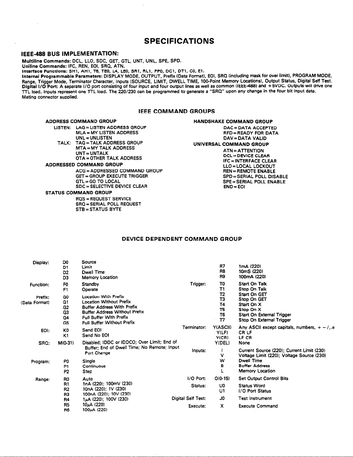
SPECIFICATIONS
IEEE-488 BUS IMPLEMENTATION:
Multiline Commands: DCL, LLO, SDC, GET, GTL, UNT, UNL, SPE, SPD.
Uniline Commands: IFC, REN, EOI, SRQ, ATN.
Interface Functions: SHl, AHl, T6, TE6, L4, LH), SRl, RLl, PW, DCl, DTl, CO, El.
Internal Programmable Parameters: DISPLAY MODE, OUTPUT, Prefix (Data Format), EOl, SRQ (including mask for over limit), PROGRAM MODE,
Range, Trigger Mode, Terminator Character, Inputs (SOURCE, LIMIT, DWELL TIME, 106Point Memory Locations), Output Status, Digital Self Test.
Digital l/O Port: A separate I/O port consisting of four input and four output lines as well as common (IEEE4881 and + 5VDC. Outputs will drive one
TTL load. Inputs represent one TTL load. The 220/230 can be programmed to generate a “SRQ” upon any change in the four bit input data.
Mating connector supplied.
IEEE COMMAND GROUPS
ADDRESS COMMAND GROUP
LISTEN: LAG = LISTEN ADDRESS GROUP
MLA = MY LISTEN ADDRESS
UNL= UNLISTEN
TALK: TAG =TALK ADDRESS GROUP
MTA = MY TALK ADDRESS
UNT = UNTALK
OTA=OTHER TALK ADDRESS
ADDRESSED COMMAND GROUP
ACG = ADDRESSED COMMAND GROUP
GET= GROUP EXECUTE TRIGGER
GTL = GO TO LOCAL
SDC = SELECTIVE DEVICE CLEAR
STATUS COMMAND GROUP
RQS = REQUEST SERVICE
SRQ= SERIAL POLL REQUEST
STB = STATUS BYTE
HANDSHAKE COMMAND GROUP
DAC = DATA ACCEPTED
RFD=READY FOR DATA
DAV = DATA VALID
UNIVERSAL COMMAND GROUP
ATN = ATTENTION
DCL= DEVICE CLEAR
IFC = INTERFACE CLEAR
LLO = LOCAL LOCKOUT
REN = REMOTE ENABLE
SPD = SERIAL POLL DISABLE
SPE = SERIAL POLL ENABLE
END = EOI
Display:
Function:
Prefix:
(Data Format)
EOI:
SRQ:
Program:
Range:
DO
Dl
D2
D3
Fo
Fl
GO
Gl
G2
G3
G4
G5
KO
Kl
M(O-31)
PO
Pl
P2
RO
Rl
R2
I?3
R4
R5
R6
DEVICE DEPENDENT COMMAND GROUP
Source
Limit
Dwell Time
Memory Location
Standby
Operate
Location With Prefix
Location Without Prefix
Buffer Address With Prefix
Buffer Address Without Prefix
Full Buffer With Prefix
Full Buffer Without Prefix
Send EOI
Send No EOI
Disabled: IDDC or IDDCO: Over Limit: End of
Buffer;‘End of Dwell Time; No Remote; Input
Port Change
Single
Continuous
Step
Auto
1nA (220); 100mV (230)
1OnA (220): 1V (230)
100nA (220); 1OV (230)
14 (220); 1OOV (230)
1ofi f220)
100&A (220)
Trigger:
Terminator:
Inputs:
I/O Port:
status:
Digital Self Test:
Execute:
R7
R8
R9
TO
Tl
T4
T5
T6
3-7
YIASCII)
YILF)
YfCR)
Y(DEL)
V
W
B
0015)
uo
Ul
JO
X
1mA (220)
1OmS (220)
lOOmA (220)
Start On Talk
Stop On Talk
Start On GET
Stop On GET
StartOnX
Stop On X
Start On External Trigger
Stop On External Trigger
Any ASCII except capitals, numbers, + - /,.e
CR LF
LF CR
None
Current Source (220); Current Limit (230)
Vottage Limit (220); Voltage Source (230)
Dwell Time
Buffer Address
Memory Location
Set Output Control Bits
Status Word
I/O Port status
Execute Command
Page 5
Safety Precautions
The following safety precautions should be observed before using
this product and any associated instrumentation. Although some instruments and accessories would normally be used with non-hazardous voltages, there are situations where hazardous conditions
may be present.
This product is intended for use by qualified personnel who recognize shock hazards and are familiar with the safety precautions required to avoid possible injury. Read the operating information
carefully before using the product.
The types of product users are:
Responsible body is the individual or group responsible for the use
and maintenance of equipment, for ensuring that the equipment is
operated within its specifications and operating limits, and for ensuring that operators are adequately trained.
Operators use the product for its intended function. They must be
trained in electrical safety procedures and proper use of the instrument. They must be protected from electric shock and contact with
hazardous live circuits.
Maintenance personnel perform routine procedures on the product
to keep it operating, for example, setting the line voltage or replacing consumable materials. Maintenance procedures are described in
the manual. The procedures explicitly state if the operator may perform them. Otherwise, they should be performed only by service
personnel.
Service personnel are trained to work on live circuits, and perform
safe installations and repairs of products. Only properly trained service personnel may perform installation and service procedures.
Users of this product must bc protcctcd from electric shock at all
times. The responsible body must ensure that users arc prevented
access and/or insulated from every connection point. In some cases,
connections must be exposed to potential human contact. Product
users in these circumstances must bc trained to protect thcmsclves
from the risk of electric shock. If the circuit is capable ofopcrating
at or above 1000 volts. no conductive part of the circuit may be
exposed.
As described in the Intcmational Electrotechnical Commission
(IEC) Standard IEC 664, digital multimctcr measuring circuits
(e.g., Keithley Models I75A, 199,2000,2001, 2002. and 2010) arc
Installation Category II. All other instruments’ signal terminals arc
Installation Category I and must not bc connected to mains.
Do not connect switching cards directly to unlimited power circuits.
They are intended to bc used with impedance limited sources.
NEVER connect switching cards directly to AC mains. When connecting sources to switching cards, install protective devices to limit fault current and voltage to the card.
Before operating an instrument, make sure the line cord is connccted to a properly grounded power receptacle. Inspect the connecting
cables, test leads, and jumpers for possible wear. cracks, or breaks
before each use.
For maximum safety, do not touch the product, test cables. or any
other instruments while power is applied to the circuit under test.
ALWAYS remove power from the cntirc test system and discharge
any capacitors before: connecting or disconnecting cables or jumpers, installing or removing switching cards, or making internal
changes, such as installing or removing jumpers.
Exercise extreme caution when a shock hazard is present. Lethal
voltage may be present on cable connectorjacks or test fixtures. The
American National Standards Institute (ANSI) states that a shock
hazard exists when voltage levels greater than 30V RMS, 42.4V
peak, or 60VDC are present. A good safety practice is to expect
that hazardous voltage is present in any unknown circuit before
measuring.
Do not touch any object that could provide a current path to the
common side of the circuit under test or power line (earth) ground.
Always make measurements with dry hands while standing on a
dry, insulated surface capable of withstanding the voltage being
measured.
Page 6
The instrument and accessories must be used in accordance with its
specifications and operating instructions or the safety of the equipment may be impaired.
The WARNING heading in a manual explains dangers that might
result in personal injury or death. Always read the associated information very carefully before performing the indicated procedure.
Do not exceed the maximum signal levels of the instruments and accessories, as defined in the specifications and operating information, and as shown on the instrument or test fixture panels, or
switching card.
When fuses are used in a product, replace with same type and rating
for continued protection against fire hazard.
Chassis connections must only be used as shield connections fat
measuring circuits, NOT as safety earth ground connections.
If you are using a test fixture, keep the lid closed while power is ap-
plied to the device under test. Safe operation requires the use of a
lid interlock.
Ifa@
screw is present, connect it to safety earth ground using the
wire recommended in the user documentation.
The !
symbol on an instrument indicates that the user should re-
a
fer to the operating instructions located in the manual.
The
symbol on an instrument shows that it can source or mea-
A
sure 1000 volts or more, including the combined effect of normal
and common mode voltages. Use standard safety precautions to
avoid personal contact with these voltages.
The CAUTION heading in a manual explains hazards that could
damage the instrument. Such damage may invalidate the warranty.
Instrumentation and accessories shall not bc conncctcd to humans.
Before performing any maintenance, disconnect the line cord and
all test cables.
To maintain protection from electric shock and fire, replacement
components in mains circuits, including the power transformer, test
Icads. and input jacks, must be purchased from Keithlcy Instruments. Standard fuses, with applicable national safety approvals,
may be used if the rating and type are the same. Other components
that are not safety related may bc purchased from other suppliers as
long as they are equivalent to the original component. (Note that se-
lectcd parts should be purchased only through Keithley Instruments
to maintain accuracy and functionality of the product.) If you arc
unsure about the applicability of a replacement component, call a
Keithley Instruments office for information.
To clean an instrument, use a damp cloth or mild. water based
cleaner. Clean the exterior of the instrument only. Do not apply
cleaner directly to the instrument or allow liquids to enter or spill
on the instrument. Products that consist of a circuit board with no
case or chassis (e.g., data acquisition board for installation into a
computer) should never require cleaning if handled according to in-
structions. If the board becomes contaminated and operation is af-
fected, the board should be returned to the factory for proper
cleaning/servicing.
Rev. IO/99
Page 7
TABLE OF CONTENTS
Paragraph
1 .I
1.2
1.3
1.4
1.5
1.6
1.7
2.1
2.2
2.3
2.3.1
2.3.2
2.3.3
2.4
2.4.1
2.4.2
2.4.3
2.4.4
2.4.5
2.5
2.6
2.6.1
2.6.2
2.6.3
3.1
3.2
3.2.1
3.2.2
3.2.3
3.2.4
3.3
3.3.1
3.3.2
3.3.3
3.3.4
4.1
4.2
4.2.1
4.2.2
4.2.3
4.2.4
4.2.5
4.2.6
4.2.7
4.2.8
4.3
4.3.1
4.3.2
4.3.3
4.3.4
4.3.5
4.3.6
4.3.7
SECTION 1 - GENERAL INFORMATlON
introduction
Model 220 and 230 IEEE Interface Features..
Warranty Information.. ...................................................................................................................................................................................
Manual Addenda.. .........................................................................................................................................................................................
Safety Symbols and Terms ...........................................................................................................................................................................
Using the Model 220/230 Programming Manual. ..........................................................................................................................................
IEEE Specifications
SECTION 2 - AN OVERVIEW OF THE IEEE-488 BUS
Introduction
Bus Description.. ...........................................................................................................................................................................................
IEEE-488 Bus Lines.. ....................................................................................................................................................................................
Bus Commands.. ...........................................................................................................................................................................................
Command Codes
Command Sequences
SECTION 3 - SYSTEM CONFIGURATION
Introduction ...................................................................................................................................................................................................
Hardware Considerations.. ............................................................................................................................................................................
Software Considerations.. .............................................................................................................................................................................
SECTION 4 - OPERATION
Introduction ...................................................................................................................................................................................................
General Bus Commands.. .............................................................................................................................................................................
Device-Dependent Command Programming ................................................................................................................................................
Title Page
...................................................................................................................................................................................................
..............................................................................................................................................
.......................................................................................................................................................................................
............................................................................................
Bus Management Lines
Handshake Lines ..................................................................................................................................................................................
Data Lines
Uniline Commands..
Universal Commands..
Addressed Commands
Unaddressed Commands .....................................................................................................................................................................
Device-Dependent Commands.. ...........................................................................................................................................................
Addressed Command Sequence.. ........................................................................................................................................................
Universal Command Sequence ............................................................................................................................................................
Device-Dependent Command Sequence
Typical Systems
Bus Connections ..................................................................................................................................................................................
Primary Address Selection
Digital I/O Port.. .....................................................................................................................................................................................
Controller Interface Routines ................................................................................................................................................................
HP-85 BASIC Statements..
Interface Function Codes ......................................................................................................................................................................
Model 220/230 Interface Commands. ...................................................................................................................................................
REN (Remote Enable) ..........................................................................................................................................................................
IFC (Interface Clear). .............................................................................................................................................................................
LLO (Local Lockout). .............................................................................................................................................................................
GTL (Go To Local). ................................................................................................................................................................................
DCL (Device Clear). ..............................................................................................................................................................................
SDC (Selective Device Clear). ..............................................................................................................................................................
GET (Group Execute Trigger) ...............................................................................................................................................................
Serial Polling (SPE, SPD) .....................................................................................................................................................................
Execute (X)
Display Mode (D) ..................................................................................................................................................................................
Inputs (I, V, W, L, B). ..............................................................................................................................................................................
I/O Port (0) ...........................................................................................................................................................................................
Function (F). ..........................................................................................................................................................................................
Data Format (G). ...................................................................................................................................................................................
EOI Programming (K) ...........................................................................................................................................................................
.............................................................................................................................................................................................
..........................................................................................................................................................................................
...........................................................................................................................................................................................
........................................................................................................................................................................
..............................................................................................................................................................................
.........................................................................................................................................................................
.........................................................................................................................................................................
..................................................................................................................................................................................
.............................................................................................................................................
....................................................................................................................................................................................
...................................................................................................................................................................
...................................................................................................................................................................
. ......................................................................................................
1-l
l-l
l-l
l-l
l-1
l-l
1-l
2-l
2-l
2-l
2-l
2-2
2-2
2-3
2-3
2-3
2-3
2-3
2-3
2-4
2-4
2-6
2-6
2-6
3-1
3-1
3-l
3-l
3-3
3-4
3-4
3-4
3-5
3-5
3-6
4-l
4-l
4-l
4-l
4-2
4-2
4-2
4-3
4-3
4-3
4-4
4-6
4-6
4-6
4-8
4-8
4-8
4-10
Page 8
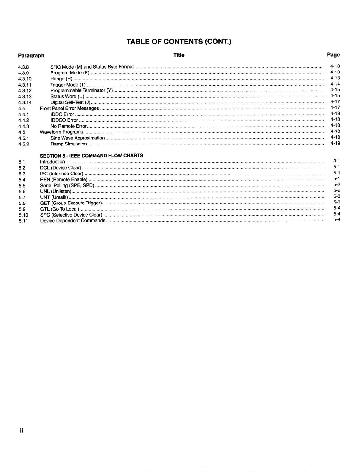
TABLE OF CONTENTS (CONT.)
Paragraph
4.3.8
4.3.9
4.3.10
4.3.11
4.3.12
4.3.13
4.3.14
4.4
4.4.1
4.4.2
4.4.3
4.5
4.5.1
4.5.2
5.1
5.2
5.3
5.4
5.5
5.6
5.7
5.8
5.9
5.10
5.11
Front Panel
Waveform
SECTION 5 - IEEE COMMAND FLOW CHARTS
Introduction ...................................................................................................................................................................................................
DCL (Device Clear).
IFC (Interface Clear)
REN
Serial
UNL
UNT (Untalk)
GET
GTL
SPC (Selective Device Clear)
Device-Dependent Commands..
Title
SRQ Mode (M) and Status Byte Format..
Program Mode (P)
Range (R) .............................................................................................................................................................................................
Trigger Mode (T) ...................................................................................................................................................................................
Programmable Terminator (Y). ..............................................................................................................................................................
Status Word (U) ....................................................................................................................................................................................
Digital Self-Test (J). ...............................................................................................................................................................................
Error Messages .........................................................................................................................................................................
IDDC Error.. ..........................................................................................................................................................................................
IDDCO Error .........................................................................................................................................................................................
No Remote Error..
Programs
Sine Wave Approximation .....................................................................................................................................................................
Ramp Simulation.. .................................................................................................................................................................................
(Remote Enable) ..................................................................................................................................................................................
Polling (SPE, SPD)
(Unlisten). ..............................................................................................................................................................................................
.................................................................................................................................................................................................
(Group Execute Trigger).
(Go To Local). ........................................................................................................................................................................................
................................................................................................................................................................................
.................................................................................................................................................................................
......................................................................................................................................................................................
......................................................................................................................................................................................
.....................................................................................................................................................................................
.............................................................................................................................................................................
.......................................................................................................................................................................
.......................................................................................................................................................................
...................................................................................................................................................................
.............................................................................................................................................
Page
4-10
4-13
4-13
4-14
4-15
4-15
4-17
4-17
4-18
4-18
4-18
4-18
4-18
4-19
5-1
5-1
5-1
5-1
5-2
5-2
5-3
5-3
5-4
5-4
5-4
ii
Page 9
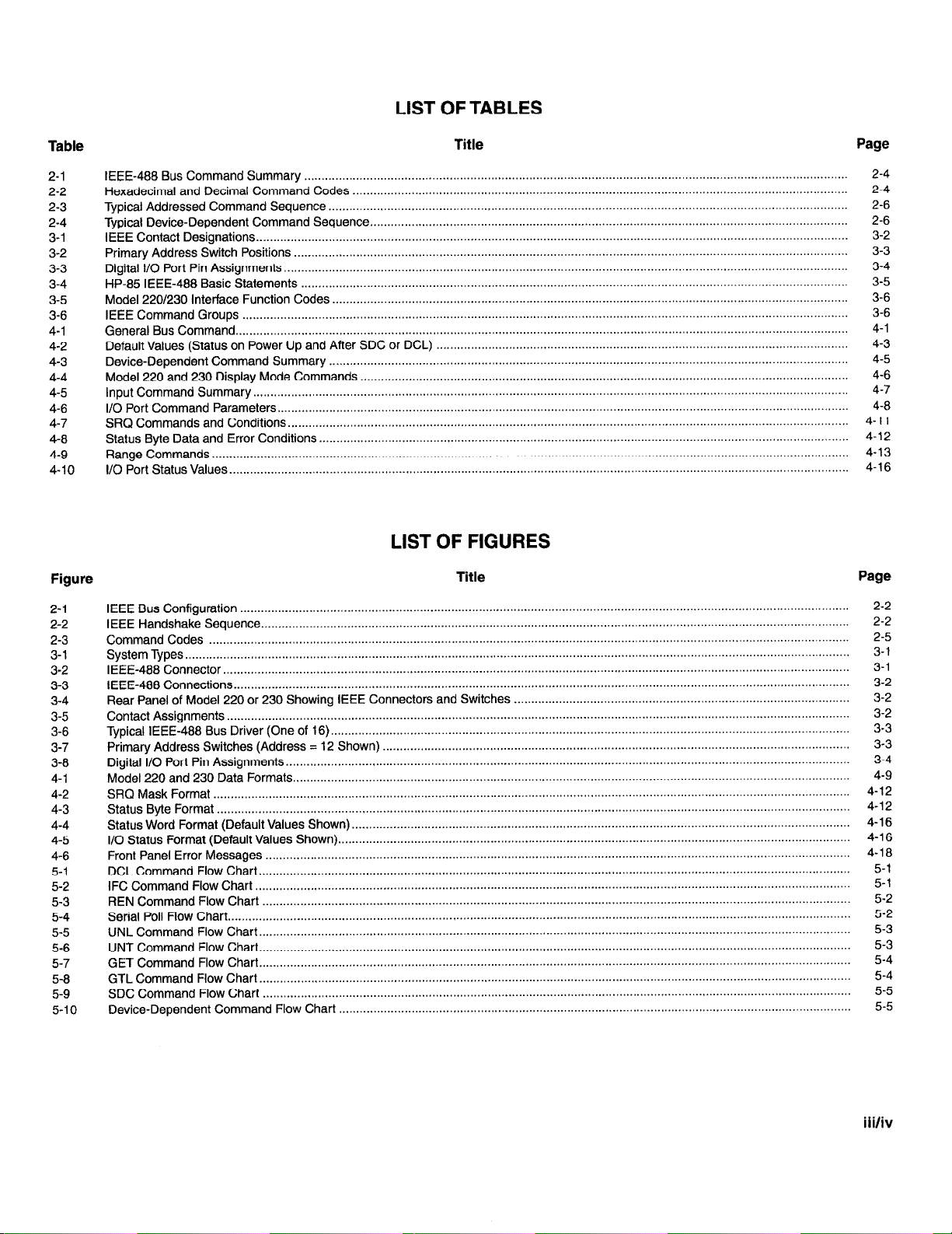
LIST OF TABLES
Table
2-l
2-2
2-3
2-4
3-l
3-2
3-3
3-4
3-5
3-6
4-1
4-2
4-3
4-4
4-5
4-6
4-7
4-8
4-9
4-10
Figure
Title Page
IEEE-488 Bus Command
Hexadecimal and
Typical Addressed Command Sequence ...................................................................................................................................................... 2-6
Typical Device-Dependent Command Sequence..
IEEE Contact Designations..
Primary Address Switch Positions ................................................................................................................................................................ 3-3
Digital I/O Port Pin Assignments
HP-85 IEEE-488 Basic Statements .............................................................................................................................................................. 3-5
Model 220/230 Interface Function Codes .....................................................................................................................................................
IEEE Command
General Bus Command..
Default Values (Status on
Device-Dependent Command Summary
Model 220 and 230 Display Mode Commands .............................................................................................................................................
Input Command Summary
l/O Port Command Parameters
SRQ Commands and Conditions
Status Byte Data and Error Conditions. ........................................................................................................................................................
Range Commands
I/O Port Status Values..
Groups ...............................................................................................................................................................................
Summary
Decimal Command
...............................................................................................................................................................................
Power Up and After SDC or DCL) .......................................................................................................................
............................................................................................................................................................................
........................................................................................................................................................................................
.................................................................................................................................................................................
............................................................................................................................................................. 2-4
.........................................................................................................................................................................
...................................................................................................................................................................
.....................................................................................................................................................................
..................................................................................................................................................................
...............................................................................................................................................
Codes
........................................................................................................................................
......................................................................................................................................................
2-4
2-6
3-2
3-4
3-6
3-6
4-l
4-3
4-5
4-6
4-7
4-8
4-11
4-12
4-13
4-16
LIST OF FIGURES
Title Page
2-l
2-2
2-3
3-1
3.2
3-3
3-4
3-5
3-6
3-7
3-8
4-1
4-2
4-3
4-4
4-5
4-6
5-1
5-2
5-3
5-4
5-5
5-6
5-7
5-8
5-9
5-10
IEEE Bus Configuration
IEEE Handshake Sequence.. ........................................................................................................................................................................
Command Codes
System Types
IEEE-488 Connector..
IEEE-488 Connections..
Rear Panel of Model 220 or 230 Showing IEEE Connectors and Switches
Contact Assignments..
Typical IEEE-488 Bus Driver (One of 16). .....................................................................................................................................................
Primary Address Switches (Address = 12 Shown)
Digital I/O Port Pin Assignments.. .................................................................................................................................................................
Model 220 and
SRQ Mask Format ........................................................................................................................................................................................
Status Byte Format
Status Word Format (Default Values Shown)
I/O Status Format (Default Values
Front Panel Error Messages
DCL Command Flow Chart
IFC Command
REN Command Flow Chart ..........................................................................................................................................................................
Serial Poll Flow Chart..
UNL Command Flow Chart..
UNT Command
GET Command Flow Chart.
GTL Command
SDC Command
Device-Dependent Command Flow Chart ....................................................................................................................................................
................................................................................................................................................................................................
230 Data
Flow Chart
................................................................................................................................................................................
.........................................................................................................................................................................................
...................................................................................................................................................................................
................................................................................................................................................................................
..................................................................................................................................................................................
.......................................................................................................................................
Formats.. ...............................................................................................................................................................
.......................................................................................................................................................................................
Shown).
.........................................................................................................................................................................
...........................................................................................................................................................................
............................................................................................................................................................................
..................................................................................................................................................................................
.........................................................................................................................................................................
Flow Chart.. .........................................................................................................................................................................
Flow Chart..
Flow Chart
..........................................................................................................................................................................
.........................................................................................................................................................................
..........................................................................................................................................................................
................................................................................................................................................
...................................................................................................................................................
.................................................................................................
2-2
2-2
2-5
3-l
3-l
3-2
3-2
3-2
3-3
3-3
3-4
4-9
4-12
4-12
4-l 6
4-16
4-l 8
5-l
5-l
5-2
5-2
5-3
5-3
5-4
5-4
5-5
5-5
iii/iv
Page 10
SECTION 1
GENERAL INFORMATION
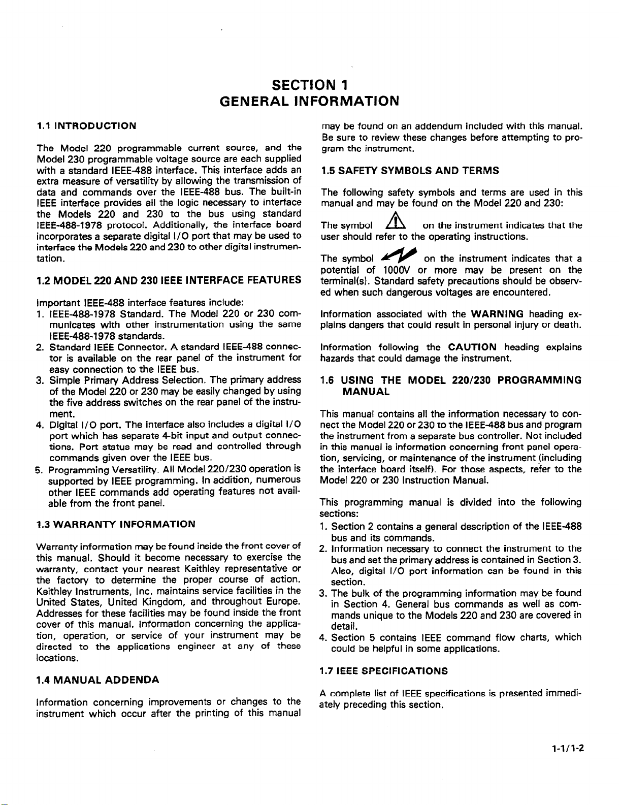
1.1 INTRODUCTION
The Model 220 programmable current source, and the
Model 230 programmable voltage source are each supplied
with a standard IEEE-488 interface. This interface adds an
extra measure of versatility by allowing the transmission of
data and commands over the IEEE-488 bus. The built-in
IEEE interface provides all the logic necessary to interface
the Models 220 and 230 to the bus using standard
IEEE-488-1978 protocol. Additionally, the interface board
incorporates a separate digital I/O port that may be used to
interface the Models 220 and 230 to other digital instrumentation.
1.2 MODEL 220 AND 230 IEEE INTERFACE FEATURES
Important IEEE-488 interface features include:
1. IEEE-4881978 Standard. The Model 220 or 230 communicates with other instrumentation using the same
IEEE488-1978 standards.
2. Standard IEEE Connector. A standard IEEE-488 connector is available on the rear panel of the instrument for
easy connection to the IEEE bus.
3. Simple Primary Address Selection. The primary address
of the Model 220 or 230 may be easily changed by using
the five address switches on the rear panel of the instrument.
4. Digital I/O port. The interface also includes a digital I/O
port which has separate 4-bit input and output connections. Port status may be read and controlled through
commands given over the IEEE bus.
5. Programming Versatility. All Model 220/230 operation is
supported by IEEE programming. In addition, numerous
other IEEE commands add operating features not available from the front panel.
1.3 WARRANTY INFORMATION
Warranty information may be found inside the front cover of
this manual. Should it become necessary to exercise the
warranty, contact your nearest Keithley representative or
the factory to determine the proper course of action.
Keithley Instruments, Inc. maintains service facilities in the
United States, United Kingdom, and throughout Europe.
Addresses for these facilities may be found inside the front
cover of this manual. Information concerning the application, operation, or service of your instrument may be
directed to the applications engineer at any of these
locations.
1.4 MANUAL ADDENDA
Information concerning improvements or changes to the
instrument which occur after the printing of this manual
may be found on an addendum included with this manual.
Be sure to review these changes before attempting to program the instrument.
1.5 SAFETY SYMBOLS AND TERMS
The following safety symbols and terms are used in this
manual and may be found on the Model 220 and 230:
The symbol ’
user should refer to the operating instructions.
The symbol
potential of 1OOOV or more may be present on the
terminal(s). Standard safety precautions should be observed when such dangerous voltages are encountered.
information associated with the WARNING heading explains dangers that could result in personal injury or death.
Information following the CAUTION heading explains
hazards that could damage the instrument.
1.6 USING THE MODEL 220/230 PROGRAMMING
MANUAL
This manual contains all the information necessary to con-
nect the Model 220 or 230 to the IEEE488 bus and program
the instrument from a separate bus controller. Not included
in this manual is information concerning front panel operation, servicing, or maintenance of the instrument {including
the interface board itself). For those aspects, refer to the
Model 220 or 230 Instruction Manual.
This programming manual is divided into the following
sections:
1. Section 2 contains a general description of the IEEE-488
bus and its commands.
2. information necessary to connect the instrument to the
bus and set the primary address is contained in Section 3.
Also, digital I/O port information can be found in this
section.
3. The bulk of the programming information may be found
in Section 4. General bus commands as well as commands unique to the Models 220 and 230 are covered in
detail.
4. Section 5 contains IEEE command flow charts, which
could be helpful in some applications.
1.7 IEEE SPECIFICATIONS
A complete list of IEEE specifications is presented immediately preceding this section.
Q
on the instrument indicates that the
on the instrument indicates that a
l-1/1-2
Page 11
SECTION 2
AN OVERVIEW OF THE IEEE-488 BUS
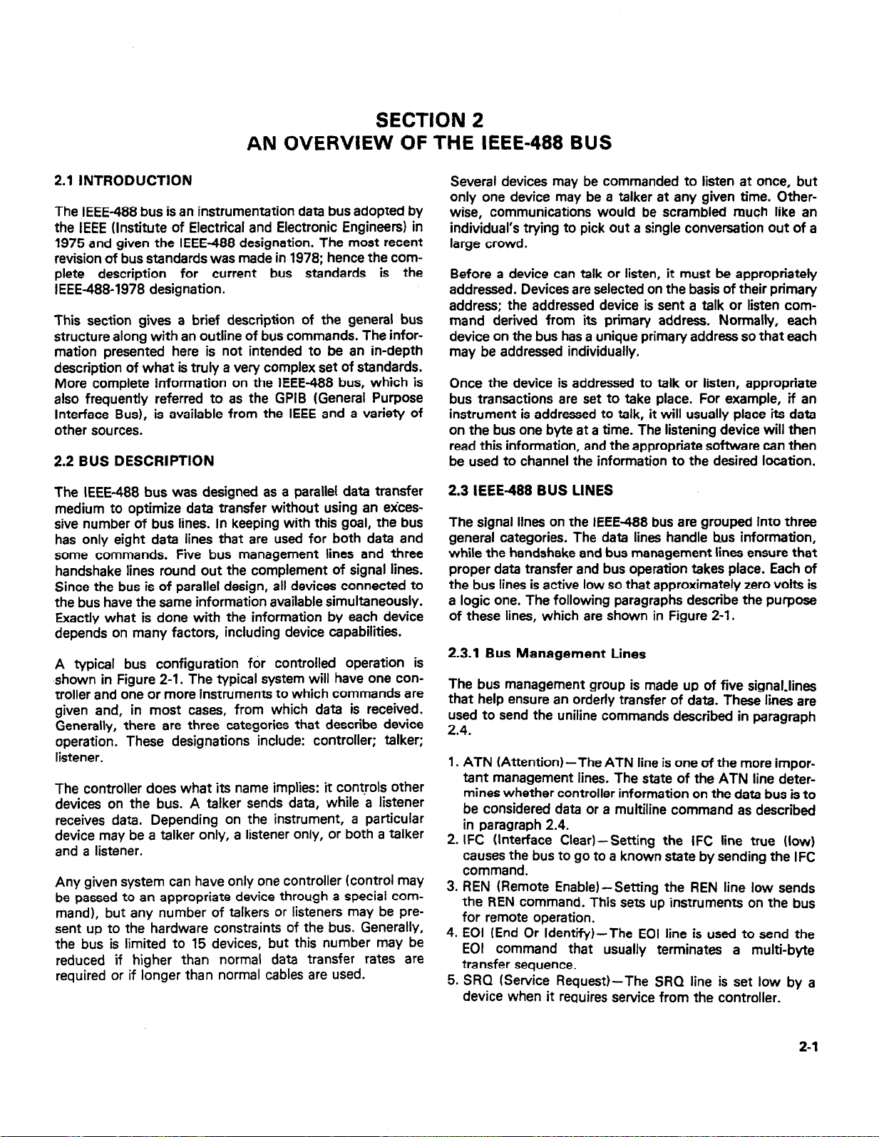
2.1 INTRODUCTDON
The IEEE-488 bus is an instrumentation data bus adopted by
the IEEE WWitute of Electrical and Electronic Engineers) in
1975 and given the IEEE488 designation. The most recent
revision of bus standards was made in 1978; hence the complete description for current bus standards is the
IEEE-488-1978 designation.
This section gives a brief description of the general bus
structure along with an outline of bus commands. The information presented here is not intended to be an in-depth
description of what is truly a very complex set of standards.
More complete information on the IEEE-488 bus, which is
also frequently referred to as the GPIB (General Purpose
Interface Bus), is available from the IEEE and a variety of
other sources.
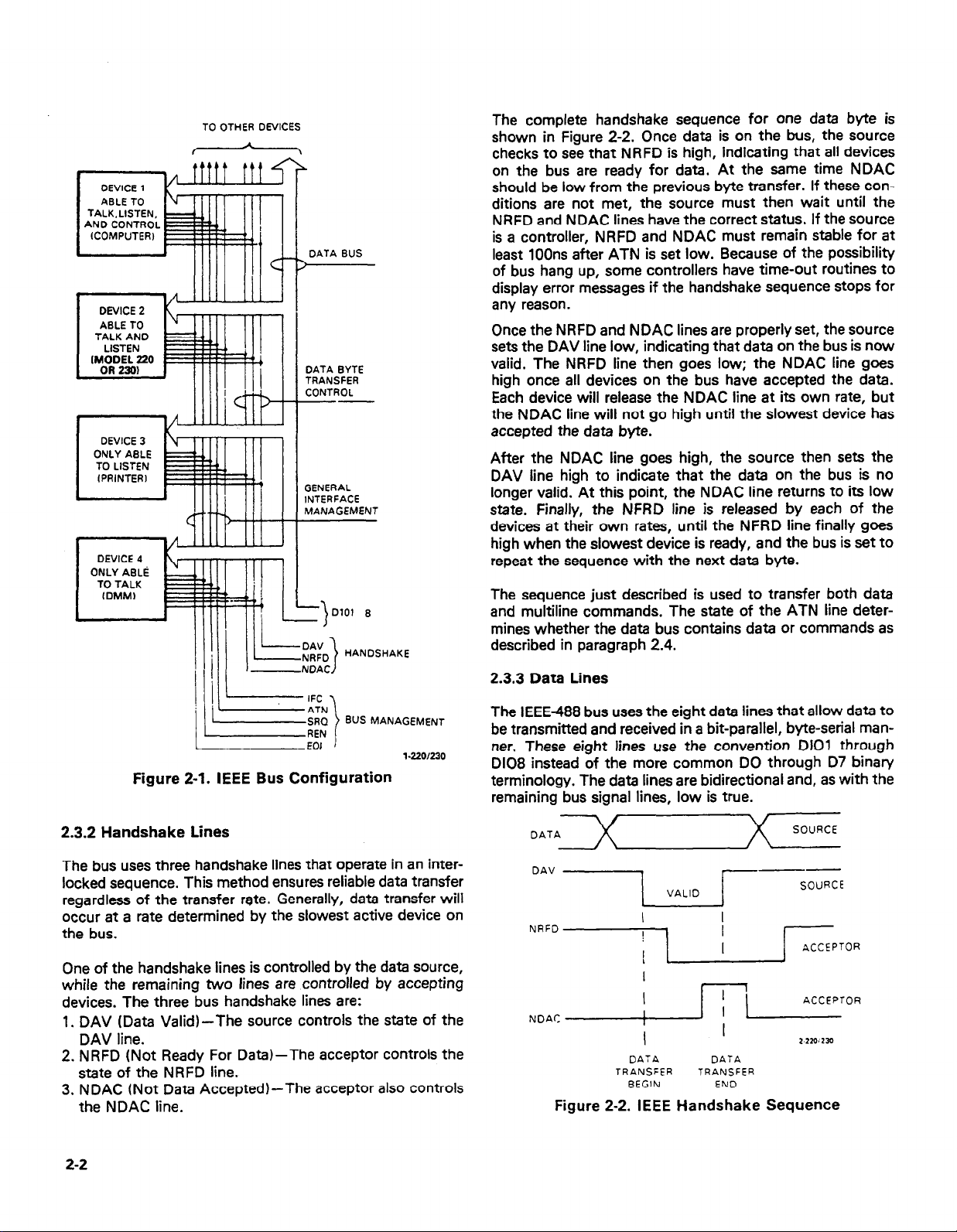
2.2 BUS DESCRIPTION
The IEEE-488 bus was designed as a parallel data transfer
medium to optimize data transfer without using an excessive number of bus lines. In keeping with this goal, the bus
has only eight data lines that are used for both data and
some commands. Five bus management lines and three
handshake lines round out the complement of signal lines.
Since the bus is of parallel design, all devices connected to
the bus have the same information available simultaneously.
Exactly what is done with the information by each device
depends on many factors, including device capabilities.
A typical bus configuration for controlled operation is
shown in Figure 2-1. The typical system will have one controller and one or more instruments to which commands are
given and, in most cases, from which data is received.
Generally, there are three categories that describe device
operation. These designations include: controller; talker:
listener.
The controller does what its name implies: it controls other
devices on the bus. A talker sends data, while a listener
receives data. Depending on the instrument, a particular
device may be a talker only, a listener only, or both a talker
and a listener.
Any given system can have only one controller (control may
be passed to an appropriate device through a special com-
mand), but any number of talkers or listeners may be present up to the hardware constraints of the bus. Generally,
the bus is limited to 15 devices, but this number may be
reduced if higher than normal data transfer rates are
required or if longer than normal cables are used.
Several devices may be commanded to listen at once, but
only one device may be a talker at any given time. Otherwise, communications would be scrambled much like an
individual’s trying to pick out a single conversation out of a
large crowd.
Before a device can talk or listen, it must be appropriately
addressed. Devices are selected on the basis of their primary
address; the addressed device is sent a talk or listen com-
mand derived from its primary address. Normally, each
device on the bus has a unique primary address so that each
may be addressed individually.
Once the device is addressed to talk or listen, appropriate
bus transactions are set to take place. For example, if an
instrument is addressed to talk, it will usually place its data
on the bus one byte at a time. The listening device will then
read this information, and the appropriate software can then
be used to channel the information to the desired location.
2.3 IEEE-488 BUS LINES
The signal lines on the IEEE-488 bus are grouped into three
general categories. The data lines handle bus information,
while the handshake and bus management lines ensure that
proper data transfer and bus operation takes place. Each of
the bus lines is active low so that approximately zero volts is
a logic one. The following paragraphs describe the purpose
of these lines, which are shown in Figure 2-l.
2.3.1 Bus Management Lines
The bus management group is made up of five signal-lines
that help ensure an orderly transfer of data. These lines are
used to send the uniline commands described in paragraph
2.4.
1. ATN (Attention)-The ATN line is one of the more important management lines. The state of the ATN line determines whether controller information on the data bus is to
be considered data or a multiline command as described
in paragraph 2.4.
2. IFC (Interface Clear)-Setting the IFC line true (low)
causes the bus to go to a known state by sending the IFC
command.
3. REN (Remote Enable)-Setting the REN line low sends
the REN command. This sets up instruments on the bus
for remote operation.
4. EOI (End Or Identify)-The EOI line is used to send the
EOI command that usually terminates a multi-byte
transfer sequence.
5. SRQ (Service Request)-The SRQ line is set low by a
device when it requires service from the controller.
2-1
Page 12
TALK.LISTEN.
AN0 dt5NTR0~
(COMPUTER) E
I
l
DEVICE 2
ABLE TO
TALK AND E
DEVICE 3
I
DEVICE 4
ONLY AELti
TO TALK
I
TO OTHER DEVICES
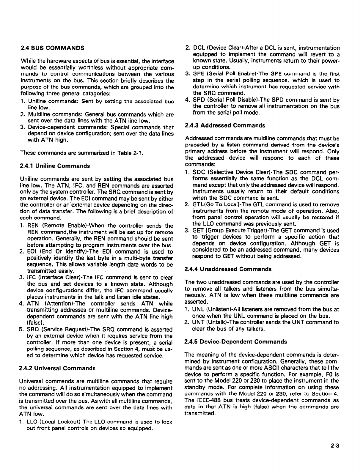
The complete handshake sequence for one data byte is
shown in Figure 2-2. Once data is on the bus, the source
checks to see that NRFD is high, indicating that all devices
on the bus are ready for data. At the same time NDAC
should be low from the previous byte transfer. If these conditions are not met, the source must then wait until the
NRFD and NDAC lines have the correct status. If the source
is a controller, NRFD and NDAC must remain stable for at
DATA BUS
)
4
least 100ns after ATN is set low. Because of the possibility
of bus hang up, some controllers have time-out routines to
display error messages if the handshake sequence stops for
any reason.
lllll
Once the NRFD and NDAC lines are properly set, the source
sets the DAV line low, indicating that data on the bus is now
DATA BYTE
TRANSFER
CONTROL
--
valid. The NRFD line then goes low; the NDAC line goes
high once all devices on the bus have accepted the data.
Each device will release the NDAC line at its own rate, but
the NDAC line will not go high until the slowest device has
accepted the data byte.
After the NDAC line goes high, the source then sets the
GENERAL
INTERFACE
MANAGEMENT
DAV line high to indicate that the data on the bus is no
longer valid. At this point, the NDAC line returns to its low
state. Finally, the NFRD line is released by each of the
devices at their own rates, until the NFRD line finally goes
high when the slowest device is ready, and the bus is set to
repeat the sequence with the next data byte.
The sequence just described is used to transfer both data
and multiline commands. The state of the ATN line determines whether the data bus contains data or commands as
described in paragraph 2.4.
1 =E) BUS MANAGEMENT I
EOI 1
1.220/230
Figure 2-1. IEEE Bus Configuration
2.3.2 Handshake Lines
The bus uses three handshake lines that operate in an interlocked sequence. This method ensures reliable data transfer
regardless of the transfer rate. Generally, data transfer will
occur at a rate determined by the slowest active device on
the bus.
One of the handshake lines is controlled by the data source,
while the remaining two lines are controlled by accepting
devices. The three bus handshake lines are:
1. DAV (Data Valid)-The source controls the state of the
DAV line.
2. NRFD (Not Ready For Data)-The acceptor controls the
state of the NRFD line.
3. NDAC (Not Data Accepted)-The acceptor also controls
the NDAC line.
2.3.3 Data Lines
The IEEE-488 bus uses the eight data lines that allow data to
be transmitted and received in a bit-parallel, byte-serial manner. These eight lines use the convention DIOI through
D108 instead of the more common DO through D7 binary
terminology, The data lines are bidirectional and, as with the
remaining bus signal lines, low is true.
OAV
NRFO
NoAC
VALID
I
I
I
/ ’ j/j ’ ACCEPTOR
I
DATA DATA
TRANSFER
BEGIN
---
I
I
TRANSFER
END
SOURCE
ACCEPTOR
2.210~233
Figure 2-2. IEEE Handshake Sequence
2-2
Page 13
2.4 BUS COMMANDS
While the hardware aspects of bus is essential, the interface
would be essentially worthless without appropriate com-
mands to control communications between the various
instruments on the bus. This section briefly describes the
purpose of the bus commands, which are grouped into the
following three general catagories:
1. Uniline commands: Sent by setting the associated bus
line low.
2. Multiline commands: General bus commands which are
sent over the data lines with the ATN line low.
3. Device-dependent commands: Special commands that
depend on device configuration; sent over the data lines
with ATN high.
These commands are summarized in Table 2-l.
2.4.1 Uniline Commands
Uniline commands are sent by setting the associated bus
line low. The ATN, IFC, and REN commands are asserted
only by the system controller. The SRQ command is sent by
an external device. The EOI command may be sent by either
the controller or an’external device depending on the direction of data transfer. The following is a brief description of
each command.
1. REN (Remote Enable)-When the controller sends the
REN command,the instrument will be set up for remote
operation. Generally, the REN command should be sent
before attempting to program instruments over the bus.
2. EOI (End Or Identify)-The EOI command is used to
positively identify the last byte in a multi-byte transfer
sequence. This allows variable length data words to be
transmitted easily.
3. IFC (Interface Clear)-The IFC command is sent to clear
the bus and set devices to a known state. Although
device configurations differ, the IFC command usually
places instruments in the talk and listen idle states.
4. ATN (Attention)-The controller sends ATN while
transmitting addresses or multiline commands. Devicedependent commands are sent with the ATN line high
(false).
5. SRQ (Service Request)-The SRQ command is asserted
by an external device when it requires service from the
controller. If more than one device is present, a serial
polling sequence, as described in Section 4, must be used to determine which device has requested service.
2.4.2 Universal Commands
Universal commands are multiline commands that require
no addressing. All instrumentation equipped to implement
the command will do so simultaneously when the command
is transmitted over the bus. As with all multiline commands,
the universal commands are sent over the data lines with
ATN low.
1. LLO (Local Lockout)-The LLO command is used to lock
out front panel controls on devices so equipped.
2. DCL (Device Clear)-After a DCL is sent, instrumentation
equipped to implement the command will revert to a
known state. Usually, instruments return to their powerup conditions.
3. SPE (Serial Poll Enable)-The SPE command is the first
step in the serial polling sequence, which is used to
determine which instrument has requested service with
the SRQ command.
4. SPD (Serial Poll Disable)-The SPD command is sent by
the controller to remove all instrumentation on the bus
from the serial poll mode.
2.4.3 Addressed Commands
Addressed commands are multiline commands that must be
preceded by a listen command derived from the device’s
primary address before the instrument will respond. Only
the addressed device will respond to each of these
commands:
1. SDC (Selective Device Clear)-The SDC command performs essentially the same function as the DCL command except that only the addressed device will respond.
Instruments usually return to their default conditions
when the SDC command is sent.
2. GTL(Go To Local)-The GTL command is used to remove
instruments from the remote mode of operation. Also,
front panel control operation will usually be restored if
the LLO command was previously sent.
3. GET (Group Execute Trigger)-The GET command is used
to trigger devices to perform a specific action that
depends on device configuration. Although GET is
considered to be an addressed command, many devices
respond to GET without being addressed.
2.4.4 Unaddressed Commands
The two unaddressed commands are used by the controller
to remove all talkers and listeners from the bus simultaneously. ATN is low when these multiline commands are
asserted.
1. UNL (Unlistenj-All listeners are removed from the bus at
once when the UNL command is placed on the bus.
2. UNT (Untalkj-The controller sends the UNT command to
clear the bus of any talkers.
2.4.5 Device-Dependent Commands
The meaning of the device-dependent commands is determined by instrument configuration. Generally, these commands are sent as one or more ASCII characters that tell the
device to perform a specific function. For example, FO is
sent to the Model 220 or 230 to place the instrument in the
standby mode. For complete information on using these
commands with the Model 220 or 230, refer to Section 4.
The IEEE-488 bus treats device-dependent commands as
data in that ATN is high (false) when the commands are
transmitted.
2-3
Page 14
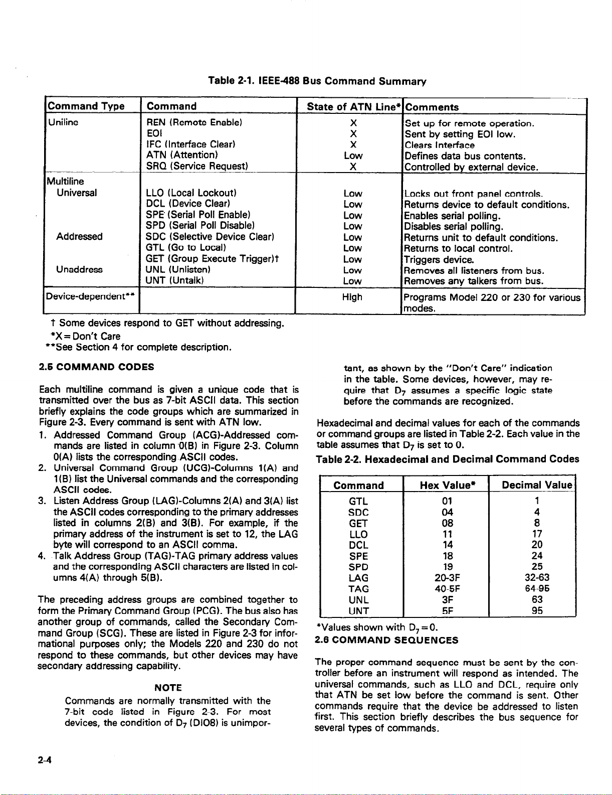
Table 2-1. IEEE488 Bus Command Summary
Command Tvoe
Jniline
Aultiline
Universal
Addressed
Unaddress
C
Device-dependent**
1
- _ -- .
‘t Some devices respond to GET without addressing.
*X = Don’t Care
**See Section 4 for complete description.
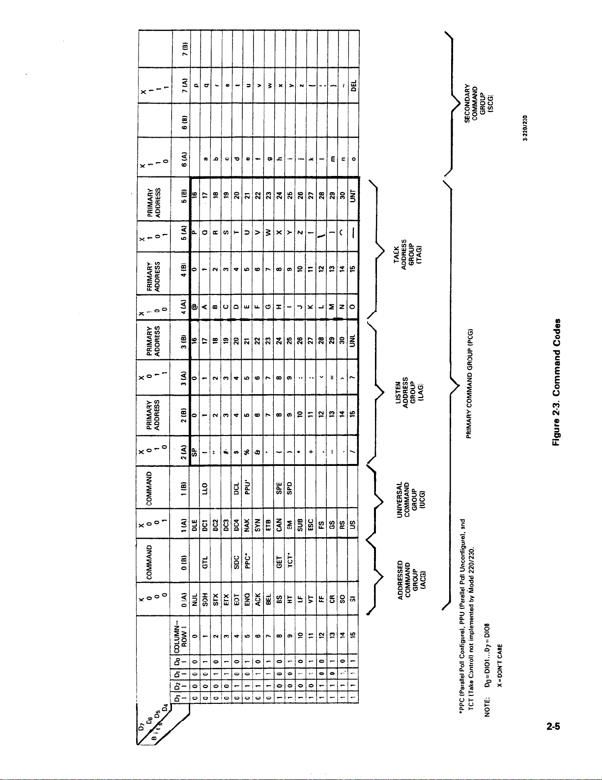
2.5 COMMAND CODES
Each multiline command is given a unique code that is
transmitted over the bus as 7-bit ASCII data. This section
briefly explains the code groups which are summarized in
Figure 2-3. Every command is sent with ATN low.
1. Addressed Command Group (ACGI-Addressed commands are listed in column ,0(B) in Figure 2-3. Column
O(A) lists the corresponding ASCII codes.
2. Universal Command Group WCGI-Columns l(A) and
1 (BI list the Universal commands and the corresponding
ASCII codes.
3. Listen Address Group (LAGKolumns 2(A) and 3(A) list
the ASCII codes corresponding to the primary addresses
listed in columns 2(B) and 3(B). For example, if the
primary address of the instrument is set to 12, the LAG
byte will correspond to an ASCII comma.
4. Talk Address Group (TAG)-TAG primary address values
and the corresponding ASCII characters are listed in columns 4(A) through 5(B).
The preceding address groups are combined together to
form the Primary Command Group (PCG). The bus also has
another group of commands, called the Secondary Com-
mand Group (SCG). These are listed in Figure 2-3 for informational purposes only; the Models 220 and 230 do not
respond to these commands, but other devices may have
secondary addressing capability.
Commands are normally transmitted with the
7-bit code listed in Figure 2-3. For most
devices, the condition of 07 (Dl08) is unimpor-
1 Command
REN (Remote Enable)
EOI
IFC (Interface Clear)
ATN (Attention)
SRQ (Service Request)
LLO (Local Lockout)
DCL (Device Clear)
SPE’ (Serial Poll Enable)
SPD (Serial Poll Disable)
SDC (Selective Device Clear)
GTL (Go to Local)
GET (Group Execute TriggerIt
UNL KInlisten)
UNT (Untalk)
I
I
NOTE
1 State of ATN Line
X
X
X
Low
X
tant, as shown by the “Don’t Care” indication
in the table. Some devices, however, may require that 07 assumes a specific logic state
before the commands are recognized.
Hexadecimal and decimal values for each of the commands
or command groups are listed in Table 2-2. Each value in the
table assumes that D7 is set to 0.
Table 2-2. Hexadecimal and Decimal Command Codes
Command
GTL
SDC
GET
LLO
DCL
SPE
SPD
LAG
TAG
UNL
UNT
*Values shown with D, = 0.
2.6 COMMAND SEQUENCES
The proper command sequence must be sent by the con-
troller before an instrument will respond as intended. The
universal commands, such as LLO and DCL, require only
that ATN be set low before the command is sent. Other
commands require that the device be addressed to listen
first. This section briefly describes the bus sequence for
several types of commands.
Comments
Set up for remote operation.
Sent by setting EOI low.
Clears Interface
Defines data bus contents.
Controlled bv external device.
/Locks out front panel controls.
‘Returns device to default conditions.
Enables serial polling.
Disables serial polling.
Returns unit to default conditions.
Returns to local control.
Triggers device.
Removes all listeners from bus.
Removes any talkers from bus.
Programs Model 220 or 230 for various
modes.
Hex Value*
01
04
08
11
14
18
19
20-3F
40-5F
3F
5F
Decimal Value
1
4
8
17
20
24
25
32-63
64-95
63
95
24
Page 15
a”
k
2-5
Page 16

2.6.1 Addressed Command Sequence
Before a device will respond to one of these commands, it
must receive a LAG command derived from its primary
address. Table 2-3 shows a typical sequence for the SDC
command. The LAG command assumes that the instrument
is set at a primary address of 12.
Note that an UNL command is transmitted before the LAG,
SDC sequence. This is generally done to remove all other
listeners from the bus first so that only the addressed device
responds.
2.6.2 Universal Command Sequence
The universal commands are sent by setting ATN low and
then placing the command byte on the bus. For example,
the following gives the LLO command:
ATN*LLO
Table 2-3. Typical Addressed Command Sequence
Note that both the ATN and LLO commands are on the bus
simultaneously. Also, addressing is not necessary.
2.6.3 Device-Dependent Command Sequence
Device-dependent commands are transmitted with ATN
high. However, the device must be addressed to listen first
before the commands are transmitted. Table 24 shows the
sequence for the following command:
FOX
This command, which sets the Model 220 or 230 to the
standby mode, is described in detail in Section 4.
Step
1 UNL set low ? 3F 63
2 LAG” stays low
3 SDC stays low 04 4
4 Returns high
*Assumes primary address= 12.
Table 24. Typical Device-Dependent Command Sequence
1 Step 1 Command 1 ATN State
Command
ATN State
Data Bus
ASCII Hex Decimal
2c 44
EbT
Data Bus
ASCII Hex
1 1 1 g pi&w;
*Assumes primary address= 12.
Decimal
63
44
70
48
88
r
2-6
Page 17

SECTION 3
SYSTEM CONFIGURATION
3.1 INTRODUCTION
There are two operating aspects to almost any digital interface. The IEEE488 standard is no exception to this rule. Not
only must the hardware meet certain standards, but all
devices, including the controller, must have appropriate
software. This section deals with important hardware and
software aspects of bus operation. Also included is information pertaining to the Model 220/230 digital I/O port.
3.2 HARDWARE CONSIDERATIONS
Before the Model 220 or 230 can be used .with the IEEE488
bus, the instrument must be connected to the bus with a
suitable connector. Also, the primary address must be properly selected as described in this section.
3.2.1 Typical Systems
The IEEE488 bus is a parallel interface system. As a result,
adding more devices is simply a matter of using more cables
to make the desired connections. Because of this flexibility,
system complexity can range from the very simple to extremely complex.
Figure 3-l shows two typical system configurations. Figure
3-l(a) shows the simplest possible controlled system. The
controller is used to send commands to the instrument,
which sends data back to the controller.
The system becomes more complex in Figure 3-l(b), where
additional instrumentation is added. Depending on programming, all data may be routed through the controller, or
it may be transmitted directly from one instrument to
another.
For very complex applications, a much larger computer can
be used. Tape drives or disks can then be used to store data.
3.2.2 Bus Connections
The Model 220 or 230 is connected to the bus through an
IEEE488 connector which is shown in Figure 3-2. This connector is designed to be stacked to allow a number of
parallel connections on one instrument.
f
\
220 OR 230
(Al SIMPLE SYSTEM
CONTROLLER
(El ADDITIONAL INSTRUMENTATION
Figure 3-l. System Types
CONTROLLER
4-220/230
S-220/230
Figure 3-2. IEEE488 Connector
NOTE
To avoid possible mechanical damage, it is
recommended that no more than three connectors be stacked on any one instrument. Otherwise, the resulting strain may cause internal
damage.
A typical connecting scheme for the bus is shown in Figure
3-3. Each cable normally has the standard IEEE connector
on each end. The Keithley Model 7008 cable, which is six
feet in length, is ideal for this purpose. Once the connec-
tions are made, the screws should be tightened securely.
For the location of the connector on the rear panel of the
Model 220 or 230, refer to Figure 34.
3-1
Page 18

Instrument
Instrument
Figure 3-3. IEEE-488 Connections
1 01
Al
A2
A3
A4
a
DIGITAL l/O
Figure 3-4. Rear Panel of Model 220 or 230 Showing
IEEE Connectors and Switches
NOTE
The IEEE-488 bus is limited to a maximum of
15 devices, including the controller. Also, the
maximum cable length is 20 meters. Failure to
observe these limits will probably result in
erratic bus operation.
Custom cables may be constructed using the information in
Table 3-l and Figure 3-5. Table 3-l lists the contact assignments for the various bus lines, while Figure 3-5 shows
contact designations. Contacts 18 through 24 are return
lines for the indicated signal lines, and the cable shield is
connected to contact 12. Each ground line is connected to
digital common in the Model 220 or 230, but contact 12
within the instrument is left unconnected to avoid ground
loops.
Table 3-1. IEEE Contact Designations
Contact
Number
1
2
3
4
5 EOI (24)*
6 DAV
7
8
9
10
11 ATN
12
13
14
15
16
17 REN (24)*
18 Gnd, (6)*
19 Gnd, (7)*
20
21 Gnd, (9)*
22 Gnd, (lo)*
23 Gnd, (1 l)*
24
l Numbers in parentheses refer to signal ground return of referenced
contact number. EOI and REN signal lines return on contact 24.
** The cable shield is normally connected to contact 12. This shield
should be connected to ground only at the controller end to avoid
ground loop problems.
CONTACT 13
IEEE-488
Designation
DlOl
D102
D103
0104
NRFD
NDAC
IFC
SRQ
SHIELD**
Dl05
D106
D107
D108
Gnd, (8)*
Gnd, LOGIC
Type
Data
Data
Data
Data
Management
Handshake
Handshake
Handshake
Management
Management
Management
Ground
Data
Data
Data
Data
Management
Ground
Ground
Ground
Ground
Ground
Ground
Ground
CONTACT 24
NOTE
The connector supplied with the Hewlett-
Packard 85 HP-B interface will require the use
of the Keithley Model 7010 IEEE cable adapter.
The HP-B cable connector has an unusually
large shoulder that prevents the cable
connector from seating properly on the IEEE
connector on the rear panel of the Model 220
or 230. Connectors on other cables, including
those on the Keithley Model 7008, should seat
properly without this adapter.
3-2
CONTACT 1
CONTACT 12
Figure 3-5. Contact Assignments
Page 19

A typical signal line bus driver is shown in Figure 3-6. With
the configuration shown, the driver has bidirectional
capability. When the I/O control line is high, the line is configured as an output line. When the control line is low, the
driver is set up for input operation. Note that not all signal
lines have bidirectional capability. Some lines, such as ATN,
will always be configured as an ouput line in the controller
and as an input line for all other devices on the bus.
DATA
LINE ’
I/O
CONTROL >
Figure 3-6. Typical IEEE-488 Bus Driver (One of 16)
3.2.3 Primary Address Selection
The Model 220 or 230 must receive a listen command
before it will respond to addressed commands. Similarly,
the instrument must receive a talk command before it will
transmit its data string, status word, or status byte. These
listen and talk commands are derived from the instrument’s
primary address. The Model 220 is shipped from the factory
with a primary address of 12. The factory set value for the
primary address of the Model 230 is 13. The primary address
may be set to any value between 0 and 30 as long as address
conflicts with other bus instruments are avoided. This may
be done by placing the primary address switches, which are
shown in Figure 3-7, in the desired positions. Note that the
primary address of the instrument must agree with the address specified in the controller’s programming language.
The primary address switch positions are read
only upon power-up. If the address is changed,
the Model 220 or 230 must be turned off and
then powered up again before the new address
can be used. The primary address is shown on
the display for a short period after power-up as
follows: IE nn, where nn represents the primary
address value.
7
0
NOTE
--o 51017
OUTPUT
%?20/230
Table 3-2. Primary Address Switch Positions
Primary Address
(Decimal Value)
0
1
z
4
5
6
7
:
10
11
12’
13””
14
15
18
17
18
19
20
21
22
23
24
25
26
;;
29
30
*Model 220 factory set value.
**Model 230 factory set value.
NOTE: Primary Address 31 (11111) is reserved for UNL and
UNT commands and should not be used.
T
Switch Positions
A5 A4 A3
-
0
0
0
0
0
0
0
0
0
0
0
0
0
0
0
0
1
1
1
1
1
1
1
1
1
1
1
1
1
1
1
0
0
0
0
0
0
0
0
1
0
1
0
0
1
0
1
:,
1
0
1
0
1
0
1
1
1
1
1
1
1
1
0
0
0
0
:
0
0
1
0
0
1
1
0
0
1
:,
1
1
ii
0
1
1
1
1
1
1
1
-
-
A2
-T
0
1
1
0
0
1
1
0
0
1
1
0
0
1
1
0
0
1
1
0
0
1
il
0
1
1
0
0
1
-
Al
0
1
0
1
0
1
0
:,
1
0
1
0
1
0
1
0
1
0
1
0
1
0
1
0
:,
:,
1
0
- J
1 0
Figure 3-7 shows the correct positions for the Model 220
factory set value of 12; if a different address is required, the
primary address may be changed as outlined in Table 3-2.
NOTE
If other instrumentation is also connected to
the bus, be sure that each device has a different
primary address. If this precaution is not
observed, erratic bus operation will probably
result.
l/230
Figure 3-7. Primary Address Switches (Address = 12
Shown)
3-3
Page 20

The primary address switches are binary weighted; Al is
the least significant bit, while A5 the most significant bit.
For example, the binary value for the Model 220 factory
set primary address of 12 is 01100. Use the tip of a pen or
pencil to operate the switches.
NOTE
Instruments should not be operated with a primary address of 31 even though it is possible
to set the Model 220 or 230 address switches
to those positions (11111). This address is
reserved for the UNT and UNL commands;
erratic operation may result if primary address
31 is used.
3.2.4 Digital I/O Port
CAUTION
Pins 11 and 12 of the digital I/O port are
connected to IEEE common. Pins 1 and 2
of the port are connected to the digital +5V
power supply. These connections are for
reference only and must not be used to
power external components.
PIN #l
\
PIN it6
/
The digital I/O port is an integral part of the IEEE interface
board. This port is available for convenient connections on
the rear panel of the unit, as shown in Figure 3-4. The I/O
port has separate 4-bit inputs and outputs as summarized
in Table 3-3. Figure 3-8 shows the contact assignments for
the port.
The output bit conditions may be controlled with an I/O
port command. The status of both input and output lines
may be checked with the I/O status command. The instrument can be programmed to generate an SRQ if the sta-
tus of any input line changes. These aspects of Model 220
and 230 operation are covered in detail in Section 4.
Each output line can drive one TTL load, and each input
line represents one TTL load. The signals on these lines
must conform to standard TTL logic levels. The input lines
are pulled up to +5V through 2.2kQ resistors.
Table 3-3. Digital I/O Port Pin Assignments
Pin Number Connection
1
2
3
4
5
6
7
8
9
10
11
12
* Bit 0 = Least Significant Bit
‘* Bit 3 = Most Significant Bit
+5V (Use for reference only)
+5V (Use for reference only)
Input (Bit 3)**
Input (Bit 2)
Input (Bit 1)
Input (Bit 0)*
Output (Bit 0)*
Output (Bit 1)
Output (Bit 2)
Output (Bit 3)**
IEEE Common
IEEE Common
PIN #I2
PIN I#7
1,.220/230
Figure 3-8. Digital l/O Port Pin Assignments
3.3 SOFTWARE CONSIDERATIONS
The most sophisticated computer in the world would be
useless without the necessary software. This basic requirement is also true of the IEEE-488 bus, which requires
the use of handler routines as described in this section.
3.3.1 Controller Interface Routines
Before a controller can be used with the IEEE-488 interface, the user must make certain that appropriate handler
software is present within the controller. With the HP-85
computer, for example, the HP-85 interface card must be
used with an additional I/O ROM, which contains the necessary handler software.
Other small computers that can be used as controllers
have limited IEEE command capability. The PETICBM
computers, for example, are incapable of sending multiline
commands from BASIC, although these commands can
be sent through machine-language routines. The capabilities of other small computers depends on the particular
interface being used. Often, little software “tricks” are
required to achieve the desired results.
From the preceding discussion, the message is clear:
make sure the proper software is being used with the
interface. Often, the user may incorrectly suspect that a
hardware problem is causing fault, when it was the software that was causing the problem all along.
3-4
Page 21

3.3.2 HP-85 BASIC Statements
Many of the programming instructions covered in Section 4
use examples written in Hewlett-Packard Model 85 BASIC.
The HP-85 was chosen for these examples because it has a
large number of BASIC statements that control IEEE-488
operation. This section covers those HP-85 BASIC statements that are essential to Model 220 and 230 operation.
A complete list of HP-85 IEEE-488 BASIC statements is
shown in Table 34. All the statements in the table have one
or three digit arguments that must be specified. The first
digit is the HP85 interface select code, which is set to 7 at
the factory. The last two digits of those statements that
require a three digit argument specfi the primary address.
Generally, only those commands that actually require an address to be sent over the bus require that the primary address be specified in the BASIC statement.
Those statements in the table with three digit arguments
assume that the primary address of the device is set at 12.
Other primary addresses require that the last two digits be
set to the corresponding value. For example, to send a GTL
command to device 22, the following BASIC statement
would be used: LOCAL 722.
Some of the statements in the table have two forms; the ex-
act configuration used depends on the desired command.
For example, CLEAR 7 will cause a DCL to be sent, while
CLEAR 712 causes an SDC to be transmitted to device 12.
The third column of Table 3-4 lists the mnemonics for the
command sequences. While most of these are covered elsewhere, a couple of points should be noted. As described
earlier, the ATN line is set low by the controller if the data
bus contains a multiline command. This is indicated in the
table by ANDing the ATN mnemonic with the first com-
mand on the bus. For example, ATN@GET means that ATN
and GET are sent simultaneously.
Two commands not previously covered are MLA (My Listen
Address) and MIA (My Talk Address). These are ordinary
PCG (Primary Command Group) addresses sent, by the
HP-85 to facilitate bus operation in some situations. The
Model 220 or 230 will essentialfy ignore these commands,
but other devices may require that MLA and MTA be
present in the command sequence under certain circumstances.
NOTE
The HP-85 address is set to 21 at the factory.
Since each device on the bus must have a
unique primary address, do not set the Model
220 or 230 to the controller’s address to avoid
possible conflicts.
3.3.3 Interface Function Codes
The interface function codes are part of the IEEE-4881978
standards. These codes define an instrument’s ability to
support various interface functions and should not be confused with programming commands found elsewhere in this
manual.
Table 3-5 lists the codes for the Models 220 and 230. These
codes are also listed for convenience on the rear panel of the
instrument immediately above the IEEE connector. The
numeric value following each one or two letter code defines
Model 220/230 capabilities as follows:
Statement
ABORT10 7
CLEAR 7
CLEAR 712
ENTER 712;AS
LOCAL 7
LOCAL 712
LOCAL LOCKOUT 7
OUTPUT 712;AS
REMOTE 7
REMOTE 712
RESET 7
SPOLL(712)
TRIGGER 7
TRIGGER 712
Table 3-4. HP-85 IEEE-488 BASIC Statements
Action
Send IFC.
Send DCL.
Send SDC to device 12.
Device 12 addressed to talk.
Date placed in A$.
Set REN False
Send GTL to device 12.
Send LLO.
Device 12 addressed to listen.
Transmit A$.
Set REN true.
Set REN true. Address device
12 to listen.
Send IFC, cancel REN.
Address device 12 to talk.
Conduct serial poll.
Send GET without addressing.
Address device 12 to listen.
Send GET.
Bus Command Sequence
IFC
ATNeDCL
ATN.UNkMTA;LAG;SDC
ATN@UNL;MLA;TAG;ATN;data
REN
ATN.UNL;MTA;lAG;GTL
ATNeLL
ATN*MTA;UNL;LAG;Am;data
REN
REN;ATN*UNL;MTA;LAG
IFC;REN;m
ATN.UNL;MLA;TAG;SPE;ATN;
status byte;ATN@SPD;UNT
ATN*GET
ATNeUNL;MTA;LAG:GET
3-5
Page 22

1. SH (Source Handshake Function)-The ability for the
Model 220/230 to initiate the transfer of message/data
on the data bus is provided by the SH function.
2. AH (Acceptor Handshake Function)-The ability for the
Model 220/230 to guarantee proper reception of
message/data on the data bus is provided by the AH
function.
3. T (Talker Function)-The ability for the Model 220/230
to send device-dependent data over the bus (to other
devices) is provided by the T function. Model 220/230
talker capabilities exist only after the instrument has
been addressed to talk.
4. L (Listener Function)-The ability for the Model 220/230
to receive device-dependent data over the bus (from
other devices) is provided by the L function. Listener
function capabilities of the Model 220 or 230 exist only
after it has been addressed to listen.
5. SR (Service Request Function)-The ability for the
Model 220/230 to request service from the controller is
provided by the SR function.
6. RL (Remote-Local Function)-The ability for the Model
220/230 to be placed in the remote or local modes is
provided by the RL function.
7. PP (Parallel Poll Function)-The Model 220/230 does not
have parallel polling capabilities.
8. DC (Device Clear Function)-The ability for the Model
220/230 to be cleared (initialized) is provided by the DC
function.
9. DT (Device Trigger Function)-The ability for the Model
220/230 to have its basic operation started (begin program operation) is provided by the DT function.
10. C (Controller Function)-The Model 220/230 does not
have controller capabilities.
11. TE (Extended Talker Capabilities)-The Model 220/230
does not have extended talker capabilities.
12. LE (Extended Listener Capabilities)-The Model 220/230
does not have extended listener capabilities.
Table 3-5. Model 220/230 Interface Function Codes
3.3.4 Model 220/230 Interface Commands
Interface commands controlling Model 220 and 230 operation are listed in Table 3-6. Not included in the table are
device-dependent commands, which are covered in detail in
Section 4.
Table 3-6. IEEE Command Groups
HANDSHAKE COMMAND GROUP
DAC = DATA ACCEPTED
RFD=READY FOR DATA
DAV = DATA VALID
UNIVERSAL COMMAND GROUP
ATN = ATTENTION
DCL = DEVICE CLEAR
IFC = INTERFACE CLEAR
LLO = LOCAL LOCKOUT
REN = REMOTE ENABLE
SPD = SERIAL POLL DISABLE
SPE= SERIAL POLL ENABLE
ADDRESS COMMAND GROUP
LISTEN:
TALK: TAG=TALK ADDRESS GROUP
ADDRESSED COMMAND GROUP
STATUS COMMAND GROUP
LAG = LISTEN ADDRESS GROUP
MLA = MY LISTEN ADDRESS
UNL= UNLISTEN
MTA = MY TALK ADDRESS
UNT= UNTALK
OTA= OTHER TALK ADDRESS
ACG = ADDRESSED COMMAND GROUP
GET=GROUP EXECUTE TRIGGER
GTL = GO TO LOCAL
SDC = SELECTIVE DEVICE CLEAR
RQS = REQUEST SERVICE
SRQ= SERIAL POLL REQUEST
STB = STATUS BYTE
END = EOI
Code Interface Function
SHl Source Handshake Capability
AH1
T6
L4
SRl
RLl
PPO
DC1 Device Clear Capability
DTl
co
El
TEO
LEO
Acceptor Handshake Capability
Talker (Basic Talker, Serial Poll, Unaddressed
To Talk On LAG)
Listener (Basic Listener, Unaddressed To Lister
On TAG)
Service Request Capability
Remote/Local Capability
No Parallel Poll Capability
Device Trigger Capability
No Controller Capability
Open Collector Bus Drivers
No Extended Talker Capabilities
No Extended Listener Capabilities
Page 23

SECTION 4
OPERATION
4.1 INTRODUCTION
The Model 220 programmable current source and the Model
230 programmable voltage source are each supplied with a
standard IEEE interface. Since all IEEE operation is done
through commands given over the bus, IEEE operation precludes the use of operating controls in the usual sense.
Instead, all operating functions are controlled by program-
ming.
This section describes important programming functions in
detail. Included are: general bus commands, devicedependent commands, status word and status byte, and
other important information. The information presented in
this manual assumes that the operator is familiar with all
normal aspects of Model 220 or 230 operation, including
front panel controls. For information on front panel opera-
tion, refer to the Model 220 or 230 Instruction Manual.
The Models 220 and 230 are very similar; both instruments
are covered in this section. Most commands perform the
same functions with each instrument. Where applicable,
differences between the two instruments are covered
separately.
NOTE
Programming examples in this section assume
that the Model 220 or 230 primary address is
set to 12. Those examples with addressed commands will not function unless the primary
address of the instrument is set to that value.
Refer to Section 3 for information on setting
the primary address.
4.2 GENERAL BUS COMMANDS
General bus commands are those commands which have
the same general meaning regardless of instrument con-
figuration. These commands are grouped into two
categories:
1, Addressed Commands. These commands require that the
primary address of the instrument agrees with the primary
address in the controller’s programming language.
2. Unaddressed Commands. No primary address is required
for these commands. All devices equipment to implement
these commands will do so simultaneously when the
command is sent.
General bus commands are summarized in Table 4-1, which
also lists the HP-85 BASIC statement that sends each com-
mand. Each addressed command statement assumes a
priman/ address of 12.
Table 4-1. General Bus Command
Addressing
Command
REN
IFC
LLO
GTL
DCL
SDC
GE-I-”
GET’
*GET may be sent with or without addressing.
4.2.1 REN (Remote Enable)
The remote enable command is sent to the Model 220/230
by the controller to set the instrument up for remote operation. Generally, this should be done before attempting to
program the instrument over the bus. The Model 220 or 230
will indicate that it is in the remote mode by illuminating its
front panel REMOTE indicator.
To place the Model 220 or 230 in the remote mode, the controller must perform the following steps:
1. Set the REN line true.
2. Address the Model 220 or 230 to listen.
Setting REN true without addressing will not
cause the REMOTE indicator to turn on;
however, once REN is true, the REMOTE light
will turn on the next time an addressed command is received.
Programming Example-This sequence is automatically
sent by the HP-85 when the following is typed into the
keyboard.
After the END LINE key is pressed, the Model 220 or 230
REMOTE indicator light should come on. If not, check to
see that the instrument is set for the proper primary address.
Also, check to see that all bus connections are tight.
4.2.2 IFC (Interface Clear)
The IFC command is sent by the controller to set the Model
220 or 230 to the talk and listen idle states. The unit will
respond to the IFC command by cancelling front panel
TALK or LISTEN lights if the instrument was previously
placed in one of those modes. No other state changes will
occur within the instrument.
Reauired 7
Yes
No
No
Yes
No
Yes
Yes
NO
NOTE
REMOTE 712 (END LINE)
HP-85 BASIC
Statement
REMOTE 712
ABORT10 7
LOCAL LOCKOUT 7
LOCAL 712
CLEAR 7
CLEAR 712
TRIGGER 712
TRIGGER 7
4-l
Page 24

To send the IFC command, the controller need only set the
IFC line true.
Programming Example-Before demonstrating the IFC
command, turn on the front panel REMOTE and TALK indicator lights by entering the following statements into the
HP-85 computer:
‘REMOTE 712 (END LINE)
ENTER 712;AS (END LINE)
The front panel REMOTE and TALK indicators should now
be on. The IFC command may now be sent by entering the
following statement into the HP-85:
ABORT10 7 (END LINE)
After the END LINE key is pressed, the TALK light will turn
off, indicating the Model 220 or 230 is in the talk idle state.
Note that the remote mode is not cancelled.
4.2.3 LLO (Local Lockout)
The LLO command is sent by the controller to remove the
Model 220 or 230 from the local operating mode. Once the
unit receives the LLO command, all its front panel controls
{except POWER) will be inoperative.
NOTE
The REN bus line must be true before the instrument will respond to an LLO command.
To lock out the front panel controls of the Model 220 or
230, the controller must perform the following steps:
1. Set ATN true.
2. Send the LLO command to the instrument.
Programming Example-This sequence is automatically
performed by the HP-85 when the following statement
sequence is typed into the keyboard:
REMOTE 712 (END LINE)
LOCAL LOCKOUT 7 (END LINE)
After the END LINE key is pressed the second time, the
front panel controls are locked out. Note that no other
changes occur within the instrument; all front panel modes
remain as previously selected. Local control may be restored
by setting REN false with the following statement:
LOCAL 7 (END LINE)
4.2.4 GTL (Go To Local)
The GTL command is used to take the instrument out of the
remote mode. To send the GTL command, the controller
must perform the following sequence:
1. Set ATN true.
2. Address the Model 220 or 230 to listen.
3. Place the GTL command on the bus.
NOTE
The GTL command does not restore operation
of locked out Model 220 or 230 front panel controls. With some instruments, however, local
control operation may be restored by the GTL
command. To restore front panel control
operation of the Model 220/230, the controller
must set the REN line false.
Programming Example-if the instrument is not in the
remote and lockout modes, enter the following statements
into the HP-85 computer:
REMOTE 712 (END LINE)
LOCAL LOCKOUT 7 (END LINE)
Check to see that the REMOTE indicator is on and that the
front panel controls are locked out. The GTL command
sequence is automatically sent by the HP-85 with the
following statement:
LOCAL 712 (END LINE)
Note that the REMOTE light on the front panel turns off, but
the front panel controls are still locked out.
Front panel control operation can be restored by setting the
REN line false with the following HP-85 statement:
LOCAL 7 (END LINE)
After executing this statement, the front panel controls will
again operate.
NOTE
Setting REN false with the LOCAL 7 statement
will also take the instrument out of the remote
mode.
4.2.5 DCL (Device Clear)
The DCL command may be used to clear the Model 220 or
230, setting it to a known state. Note that all devices on the
bus equipped to respond to a DCL will do so simultaneously. When the Model 220 or 230 receives a DCL command, it will return to the default conditions listed in Table
4-2.
NOTE
Program memory will be cleared of all pre-
viously stored data when a DCL or SDC command is received. Buffer and display location
pointers will be set to location one.
To send a DCL command, the controller must perform the
following steps:
1. Set ATN true.
2. Place the DCL command on the bus.
Programming Example-Using the front panel controls,
enter current, voltage, and dwell time data into the first few
memory locations. Also, set the display to the dwell time
mode and place the instrument in the continuous program
mode; turn the output on with the OPERATE button. Now
enter the following statement into the HP-85:
REMOTE 712 (END LINE)
CLEAR 7 (END LINE)
4-2
Page 25

When the END LINE key is pressed the second time, the instrument will return to the default conditions listed in Table
4-2. The SOURCE display and STEP lights should be on and
the OPERATE light should be off. Also, program memory
will be cleared of any previously stored data.
Table 4-2. Default Values (Status On Power Up and
After SDC or DCLI
4.2.7 GET (Group Execute Trigger)
The GET command is sent to the Model 220 or 230 to trigger the instrument. Using the GET command is only one of
several methods that can be used to start or stop Model 220
or 230 program operation. More detailed information on all
trigger modes, including GET can be found in paragraph
4.3.
Mode
Display
Function
Value
DO Source
Fo Standby
Data Format GO
Self Test*
EOI
Jl
KO Send EOI
Program Mode P2
Range
Trigger
SRQ Mode
Terminator
RO Auto
T6
MO Disabled
Y(LF) CR LF
Location With Prefix
Test Performed; Power Up
Step
Start On External
Status
*Not affected by SDC or DCL; set to 1 after running
digital self test or upon power up.
4.2.6 SDC (Selective Device Clear)
The SDC command performs the same functions as the
DCL command except that only the addressed device
responds. This command is useful for clearing only a
selected instrument instead of all instruments at once. The
Model 220 or 230 will return to the default conditions listed
inTable 4-2 when responding to an SDC command.
NOTE
The program memory will be cleared of all
previously stored data when a DCL or SDC
command is received. Also, buffer and display
pointers will be set to location one.
To transmit the SDC command, the controller must perform
the following steps:
1. Set ATN true.
2. Address the Model 220 or 230 to listen.
3. Place the SDC command on the bus.
Programming Example-Enter voltage, current, and dwell
time data into the first few memory locations with the front
panel controls. Also set the display to the memory mode
and set the instrument to the single program mode. Enter
the following statements into the HP-85:
REMOTE 712 (END LINE)
CLEAR 706 (END LINE)
Note that the instrument did not respond to the SDC
because the command was sent with a primary address of
six. Now enter the following statement into the HP-85:
CLEAR 712 (END LINE)
This time, the instrument returns to the default conditions
listed in Table 4-2. Note that the program memory is cleared
of previously stored data.
To send the GET command over the bus, the controller
must perform the following sequence:
1. Set ATN true.
2. Address the Model 220 or 230 to listen.
3. Place the GET command on the bus.
GET can also be sent without addressing by omitting step 2.
Programming Example-Type in the following statements
into the HP-85 keyboard:
REMOTE 712 (END LINE)
CLEAR 712 (END LINE)
The instrument should return to the default values listed in
Table 4-2.
Place the instrument in the continuous program mode and
start-on-GET trigger mode with the following statement:
OUTPUT 712; “PlT2X” (END LINE)
When the END LINE key is pressed, the CONTINUOUS program light on the front panel of the instrument will turn on.
The instrument may be triggered to start with the following
statement:
TRIGGER 712 (END LINE)
The front panel START/STOP light will turn on, indicating
the instrument has been triggered. To stop the instrument,
enter the following statements into the HP-85 keyboard:
OUTPUT 712; “T3X” (END LINE)
TRIGGER 712 (END LINE)
When END LINE is pressed the second time, the front panel
START/STOP light will go out, showing the instrument has
received the trigger.
NOTE
The Model 220/230 will also respond to GET
without addressing. This command is sent with
the following HP-85 statement: TRIGGER 7.
The preceding examples use device-dependent commands
to place the instrument in the appropriate trigger modes.
These commands are covered in detail in paragraph 4.3.
4.2.8 Serial Polling (SPE, SPDI
The serial polling sequence is used to obtain the Model 220
or 230 status byte. Usually, the serial polling sequence is
used to determine which of several devices has requested
service over the SRQ line. However, the serial polling
4-3
Page 26

sequence may be used at any time to obtain the status byte
from the Model 220 or 230. For more information on status
byte format, refer to paragraph 4.3.8.
The serial polling sequence is conducted as follows:
1.
The controller sets the ATN line true.
2.
The SPE (Serial Poll Enable) command is placed on the
bus by the controller.
The Model 220 or 230 is addressed to talk.
3.
. 4.
The controller sets ATN false.
5.
The instrument then places its status byte on the bus to
be read by the controller.
The controller then sets the ATN line low and places SPD
6.
(Serial Poll Disable) on the bus to end the serial polling
sequence.
Steps 3 through 5 may be repeated for other instruments on
the bus by using the correct talk.address for each instru-
ment. ATN must be true when the talk address is transmitted and false when the status byte is read.
Programming .ExamplaThe HP-85 SPOLL statement
automatically performs the serial polling sequence. To
demonstrate serial polling, momentarily power down the
Model 220 or 230 and enter the following statements into
the HP-85 keyboard:
REMOTE 712 (END LINE)
S = SPOLL (712) (END LINE)
DISP S (END LINE1
When END LINE is pressed the second time, the computer
performs the serial polling sequence. When END LINE is
pressed the last time, the status byte value (0) is displayed
on the CRT. The status byte has a value of 0 with this example because no bits in the byte are set. Paragraph 4.3.8
covers the status byte format in detail.
4.3 DEVICE-DEPENDENT COMMAND PROGRAMMING
If an illegal command or command parameter is present
within a command string, the instrument will:
1. Ignore the entire command string.
2. Display appropriate front panel error messages.
3. Set certain bits in its status byte.
4. Generate an SRQ if programmed to do so.
These programming aspects are covered in paragraphs
4.3.8 and 4.4.
HP-85 examples are included throughout this section to
clarify programming.
Before using a programming example, it is recommended
that the instrument be set to its default values by sending an
SDC over the bus. See paragraph 4.2.6 for information on
using the SDC command.
NOTE
Program memory will be cleared of previously
stored data when an SDC command is sent to
the instrument.
If the HP-85 should become “hung up” at any point, operation may be restored by holding the SHIFT key down and
then pressing RESET on the keyboard.
In order to send a device-dependent command, the controller must perform the following sequence:
1, Set ATN true.
2. Address the Model 220 or 230 to listen.
3. Set ATN false.
4. Send the command string one byte at a time.
Programming Example-Device-dependent commands are
sent by the HP-85 using the following statement:
OUTPUT 712; A$
AS in this case contains the ASCII characters that form the
command string.
IEEE device-dependent commands are sent to the Model
220 or 230 to control various operating modes such as function, display mode, current or voltage output, voltage or
current limit, and program mode. Each command is made
up of an ASCII alpha character followed by one or more
numbers designating specific para’meters. For example, a
voltage value is programmed by’ sending an ASCII “v”
followed by numbers designating the actual voltage value.
The IEEE bus treats device-dependent commands as data in
that ATN is high when the commands are transmitted.
A number of commands may be grouped together in one
string. A command string is terminated by an ASCII “X”
character which tells the instrument to execute the command string. There is no limit as to the number of characters
that can be contained in one string as far as the Model 220
or 230 is concerned, although string length may be limited
by controller capabilities.
4-4
NOTE
REN must be true when attempting to program
the Model 220/230. If REN is false, the instru-
ment will respond with a no remote error
message as described in paragraph 4.4.
Commands that affect both the Model 220 current source
and the Model 230 voltage source are listed in Table 4-3.
Most commands affect both instruments in the same way.
However, some important differences between the Models
220 and 230 should be noted:
1. The DO command sets the display to view the current
source value on the Model 220 and the voltage source
value on the Model 230.
2. The Dl command sets the display to view the voltage
limit on the Model 220 and the current limit on the Model
230.
3. The I command sets the current source value on the
Model 220; it sets the current limit on the Model 230.
Page 27

Table 4-3. Device-Dependent Command Summary
Mode Command
Display
Function
Prefix
(Data Format)
EOI
SRQ
(O-31 I l
Program
Range
Trigger
Terminator
Inputs
I/O Port
Status
Diaital Self Test
Execute
*May be programmed to generate SRQ under more than one condition.
DO
Dl
D2
D3
Fo
Fl
GO
Gl
G2
G3
G4
G5
KO
Kl
MO
Ml
M2
M4
M8
Ml6
PO
Pl
P2
RO
Rl
R2
R3
R4
R5
R6
R7
R8
R9
TO
Tl
T2
T3
T4
T5
T6
T7
Y(ASCII)
Y(LF)
Y(CR)
YIDEL)
I
::
B
L
O(O-15)
.---
uo
Ul
JO
X
Model 220 Model 230
Current Source
Current Source Voltage Source
Voltage Limit Current Limit
Dwell Time
Memory Location Memory Location
Standby (Voltage Limit ( 32V)
Operate (Set to Programmed Value) Operate (Set to Programmed Value)
Location With Prefix
Location Without Prefix
Buffer Address With Prefix
Buffer Address Without Prefix
Full Buffer With Prefix
Full Buffer Without Prefix
Send EQI
Send No EOI
Disabled
IDDC, IDDCO, No Remote
Over Voltage Limit
End of Buffer
End of Dwell lime
Input Port Change
Single
Continuous
Step
Auto
1nA
10nA
lOOnA
:$I
lOOti
1mA
1OmA
lOOmA
Start On Talk
Stop On Talk
Start On GET
Stop On GFT
Start On X
Stop On X
Start On External Trigger
Stop On External Trigger
Any ASCII except capitals, numbers, + - /,.e
CR LF
LF CR
None
Current Source Current Limit
.Voltage Limit Voltage Source
Dwell Time Dwell Time
Buffer Address Buffer Address
Memory Location
Set Output Control Bits
Send Status Word
Send I/O Port Status
Test Instrument, Set J Byte in Status Word
Execute Other Device-Dependent Commands
Voltage Source
Dwell Time
Standby (Current Limit = 2mA)
Disabled
IDDC, IDDCO, No Remote
Over Current Limit
End of Buffer
End of Dwell Time
Input Port Change
Auto
100mV
1v
1ov
1oov
Memory Location
4-5
Page 28

The V command sets the voltage source value on the
4.
Model 230; it sets the voltage limit on the Model 220.
The range commands for the two instruments perform
5.
different functions. These commands affect the
output of the Model 220 and the voltage output of the
Model 230.
All the commands listed in Table 4-3 are covered in detail in
the following paragraphs.
current
Table 4-4. Model 220 and 230 Display Mode Commands
4.3.1 Execute (XI
The execute command is implemented by sending an ASCII
“X” over the bus. Its purpose is to tell the Model 220 or 230
to execute other device-dependent commands. Generally,
the “X” character is the last byte in the command string.
The execute character also controls instrument operation in
the T4 and T5 trigger modes as described in paragraph
4.3.11.
NOTE
Command strings sent without an execute
character will not be executed at that time, but
they will be stored in the command buffer. The
next time an execute character is received, the
stored commands will be executed, assuming
all commands in the previous string were valid.
Programming Example-Enter the following statements in-
to the HP-85 keyboard:
REMOTE 712 (END LINE)
OUTPUT 712; “x” (END LINE)
When the END LINE key is pressed the second time, the
front panel LISTEN light comes on, showing that the instru-
ment received the command. No other changes will occur
with this example because no other commands were sent.
4.3.2 Display Mode (D)
The display mode commands perform the same operations
as the four front panel DISPLAY pushbuttons on the instrument. Through use of these commands, the user can set the
display to view the source value, current (220) or voltage
(230) limit, dwell time, and memory location. The display
mode commands for both the Model 220 and 230 are sum-
marized in Table 4-4. Upon power-up, or after receiving a
DCL or SDC command, the instrument will be in the DO
display mode.
Programming Example-Set the instrument to view the
source value with the front panel SOURCE button and enter
the following statements into the HP-85 keyboard:
REMOTE 712 (END LINE)
OUTPUT 712; “D3X” (END LINE)
After this statement sequence is executed, the instrument
display will show the memory location. The SOURCE in-
dicator will be off, and the MEMORY light will be on.
4.3.3 Inputs (I,V,W,L,B)
The input commands control current, voltage, and dwell
times that can be stored within the various memory locations in the instrument. In addition, two of the commands
control pointers that determine the actual memory location
into which data is to be stored.
The Models 220 and 230 each have a 100 point memory for
program data storage. In order to easily identify any one of
these locations for data storage, two separate pointers are
used. The display location pointer points to the memory
location displayed on the front panel; data entered from the
front panel will be stored in this location. The IEEE buffer
address pointer points to the location into which input command (I,V,W) data is to be stored.
NOTE
The IEEE buffer and display location pointers
also affect data transmitted from the Model 220
or 230 to another device. In the GO and Gl
prefix modes, location pointer data will be sent;
in G2 and G3 prefix modes, buffer pointer data
will be transmitted.
The input commands that affect Model 220 and 230 operation are:
Stores the current source (Model 220) or current limit
(Model 230) into the memory slot indicated by the IEEE
buffer address pointer.
Stores the voltage source (Model 230) or voltage limit
(Model 220) into the memory slot indicated by the IEEE
buffer address pointer.
W Stores the dwell time into the memory location indicated
by the IEEE buffer address pointer.
L Sets the display location pointer to the commanded value.
B Sets the IEEE buffer address pointer to the command
value.
A complete summary of input commands along with the
format of each is shown in Table 4-5. The parameter for
each command may be entered in direct or scientific nota-
tion as long as the allowable range for each command is not
exceeded. Some examples for the various commands are
shown below.
4-6
Page 29

DESIRED RESULT
7.5mA current (Model 220) 17.5E-3; 1.0075;
6.3V voltage (Model 230)
27ms dwell time
Location pointer to #57
Buffer pointer to #86
NOTES:
1. An IDDCO (Illegal Device-Dependent Command Option)
error will occur if the input command parameter is outside the legal range. A front panel error message will indicate this error; the instrument may also be programmed
to generate an SRQ if such an error occurs, as described
in paragraph 4.3.8.
2. The Model 230 current limit may be set to only one of
three values:
I1 = 20mA limit
I2 = 100mA limit
3. A zero dwell time cannot be programmed into memory
location one.
4. Dwell time accuracy is guaranteed only if the IEEE bus is
idle.
Programming Example-Enter the following program into
,the HP-85:
PROGRAM
10 DIM A$ [lo01
20 REMOTE 712
30 CLEAR 712 @
OUTPUT 712; “MlX”
Mode
Command*
I f n.nnnnE + nn**
Vn.nnE f nn
Wn.nnnE + nn
Bn.nnE c nn
Ln.nnE + nn
NOTE: n = numeric digit
tAuto range limits shown.
*Commands may be entered in normal or scientific notation; scientific notation format shown.
**Least significant digit of mantissa must be 0 or 5.
220 Current Soul
Controls
Current Source O-101 mAt
Value, Amperes (50OfA steps)
Voltage Limit, l-105v
Volts in 1V steps
Dwell Time,
Seconds
IEEE Buffer
Address
Display Location
Pointer
COMMAND VARIATIONS
1.75E-2; l.O75E-1
V6.3; V.63El
W27E-3; W2.7E-2;
W.027
L57; L5.7El
B86; B8.6El
IO = 2mA limit
COMMENTS
Dimension A$ for 100
characters
Set instrument up for
remote operation.
Return instrument to
default conditions.
Enable SRQ on error.
Table 4-5. Input Command Summary
rc e
Allowable
Range
0;3ms to 999.95
1 to 100
1 to 100
in lms steps
40
CLEAR
50
DISP “COMMAND”;
60
INPUT A$
70
OUTPUT 712;AS
80
S = SPOLL (7121
90
IF BIT(S,5) = 0
THEN 50
100
IF BIT IS,01 THEN
DISP “ILLEGAL
COMMAND”
110
“IF BIT (S,l) THEN
DISP “ILLEGAL
COMMAND OPTION”
120
GOT0 50
END
130
After the program is entered, depress the HP-85 RUN key.
When the computer prompts for a command input, enter
the desired command, including the command letter prefix;
several commands may be grouped together in one input
string. Be sure to terminate each command string with the
execute (XI character. Programmed data may be observed
by using the front panel display. Remember that bus data is
stored in the memory slot indicated by the buffer address
pointer--not the location indicated by the display location
pointer, unless, of course, both pointers point to the same
memory location.
NOTE
Buffer pointer and location address pointer
status can be read by using the appropriate
prefix mode as described in paragraph 4.3.6.
ll-
II
Command*
V f n.nnnnE f nn**
In.nnEknn
5
Wn.nnnE+ nn
Bn.nnE k nn
Ln.nnEf nn
I
Model
IO Voltage Sour<
Controls
Voltage Source
Value, Volts
Current Limit,
Amperes
Dwell Time,
Seconds
IEEE Buffer
Address
Display Location
Pointer
Clear CRT.
Prompt for command
input.
Input command string.
Send command string to
instrument.
Conduct serial poll; read
status byte.
Check for error conditions
Check for IDDC.
Check for IDDCO.
Repeat
Range
0-101vt
(5OpV steps)
0=2mA
1 = 20mA
2= 100mA
0;3ms to 999.9s
in lms steps
1 to 100
1 to 100
4-7
Page 30

4.3.4 I/O Port (01
The I/O port command controls the status of the four output bits on the digital I/O port on the rear panel of the instrument. Information on I/O port pin assignments can be
found in Table 3-3. The I/O port command consists of the
ASCII “0” character followed by the decimal number that
sets the control bits as listed in Table 4-6. Upon power-up,
or after a DCL or SDC, the four output lines will be set low.
Table 4-6 I/O Port Command Parameters
Command
Parameter* Bit
0
0 0
1 0 0
2
3
:
4 0
5
6
0
0
7 0
8
9
10
11
12
13
14
15
1 0
1
1 :
1 0
1 1
1 1
1 1
1 1
lltput e Status
Bit 2
0
0
1
1
1
1
Bit 1
0
0
1
1
0
0
1
1
0
0
1
1
0
0
1
1
Bit 0
0
1
0
.:,
1
0
1
0
;
1
0
1
0
1
*Parameter must be preceded by ASCII letter “0”.
Programming Example-Enter the following statement
sequence into the HP-85 computer:
REMOTE 712 (END LINE)
OUTPUT 712; “015X” (END LINE)
When END LINE is pressed the second time, the four output
bits go high.
4.3.5 Function (FI
The function commands control the actual output of the
Model 220 or 230 source. These commands perform the
same operations as the front panel OPERATE button. The
output of the Model 220 and 230 may be controlled by bus
commands as follows:
FO Standby-The source output will be set to zero. (Model
220 voltage limit <32V. Model 230 current
limit = 2mA).
Fl Operate- The output will be programmed to the source
value in the present display memory location.
When END LINE is pressed the second time, the front panel
OUTPUT indicator comes on.
4.3.6 Data Format (G)
When addressed to talk, the instrument will send a data
string containing information on programmed current,
voltage, dwell time, and memory or buffer locations.
Through use of the data format command, the user has
control over the following aspects of the data string:
1. Whether or not the instrument sends appropriate prefixes
imbedded in the data string.
2. Whether the entire buffer or only one display location or
IEEE buffer location is transmitted.
Data format commands that affect Model 220 and 230
operation are:
GO Transmit display memory location with prefixes.
Gl Transmit display memory location without prefixes.
G2 Transmit IEEE buffer address location with prefixes.
G3 Transmit IEEE buffer address location without prefixes.
G4 Transmit entire program memory with prefixes.
G5 Transmit entire program memory without prefixes.
The general format for each of these commands is shown in
Figure 4-l. The most significant digit of each data element is
forced so one digit always appears to the left of the decimal
point. Returned values for both Models 220 and 230 are
shown. Upon power-up, or after receiving a SDC or DCL,
the GO mode is enabled.
NOTES:
1. The data format commands affect the format of the I/O
status and instrument status words. In the GO, G2, and
G4 modes, the word prefixes are sent. In the Gl, G3, and
G5 modes, the prefixes are omitted.
2. In the GO through G3 modes, EOI and programmed ter-
minators will be sent (if so programmed) at the end ,of
each location or buffer address. In the G4 and G5 modes,
EOI and programmed terminators will be sent only at the
end of the entire buffer transmission.
3. Transmission of the normal data string is superseded by
the status word (U) command. The instrument will trans-
mit the status word instead of the normal data string
once each time the status command is given when addressed to talk in the normal manner.
4. The “N” (Normal) prefix on the current source (220) or
voltage source (230) will change to “0” (Overlimit) if the
voltage limit (220) or current limit (230) is exceeded.
5. The entire program memory is transmitted in the G4 and
G5 modes whether or not data is stored in every location.
Programming Example-Using the front panel OPERATE
button, turn the instrument output off and enter the follow-
ing statements into the HP-85:
REMOTE 712 (END LINE)
OUTPUT 712; “FlX” (END LINE)
4-8
In order to obtain the data string from the instrument, the
controller must perform the following bus sequence:
1. Set ATN true.
2. Address the Model 220 or 230 to talk.
Page 31

Model 220 Current Source”
Current Source
NDCI i: n.nnnnE + n,
Presanm;nt
Current Source
* n.nnnnE f n,
Current Source
NDCI f n.nnnE f n,
Current Source
+ n.nnnnE t n,
Current Source
NDCI f n.nnnnE + n,
NDCI + n.nnnnE t n.
f n.nnnnE + n.
?r n.nnnnE f n.
+ n.nnnnE f n,
;--
f n.nnnTiE> K
NOTE: n = digit between 0 and g.
‘Spaces shown between groups are for clarification only and do not exist on actual data strings.
Voltage Limit Dwell Time Display Location
V f n.nnOOE + n,
Voltage Limit Dwell Time
+ n.nnOOE + n,
Voltage Limit
V & n.nnOOE + n,
Voltage Limit Dwell Time
f n.nnOOE t n.
Voltage Limit
V + n.nnOOE t n,
V + n.nnOtlE t n, W t n.nnnnE i n,
V;n nnOOEtn
-L----A ------A
V + n.nnOOE t n.
Voltage Limit
+ n.nnOOE + n,
+ n.nnOOE + n,
f n.nnOOE +s
T iiXii6UQ n,
W + n.nnnnE +_ n, L + n.nnOOE + n
Display Location
+ n.nnnnE f’n, t n.nnOOE + n
Dwell Time Buffer Address
W t n.nnnnE f n, B t n.nnOOE + n
Buffer Address
t n.nnnnE f n,
Dwell Time
W t n.nnnnE f n, Bt l.nnOOE+O,
W t n.nnnnE + n
W + n.nnnnE t n,
Dwell Time Buffer Address
+ n.nnnnE f n,
+ n.nnnnE + n, t 2.nnOOE i- 0,
t n.nnnnE f n. t 3.nnOOE + 0
mn?iz%T 6
t n.nnOOE t n
Buffer Address
B t 2nnOOE t 0,
B, 3.nnOO&O~
Btl.nnOOEt2
+ 1 .nnOOE + 0,
-----L
+ l.nnOOE+2
-.
2
.- --
Model 230 Voltage Source’
NDCV & n.nnnnE f n,
Preti’xantis’saEGent
NDCV f n.nnnE f n,
NDCV it n.nnnnE it n, I f n.nnOOE t n,
NDCV + n.nnnnE it n,
YPI;\L+~n~n~~~
--
NDCV f n.nnnnE it. n,
Voltage Source Current Limit
I + n.nnOOE f n, ‘W t n.nnnnE + n,
Voltage Source
+ n.nnnnE f n,
Voltage Source Current Limit
Voltage Source Current Limit
f n.nnnnE + n,
Voltage Source Current Limit
Voltage Source Current Limit
+ n.nnnnE f n, f n.nnOOE t n,
f n.nnnnE f n,
t n.nnnnE f L
---+ n.nnnnE f n, rn%%fi n,
Current Limit
f n.nnOOE & n.
I + n.nnOOE f n,
+ n.nnOOE f n,
If n.nnCtOE t n, W t n.nnnnE f n,
kamWk.n, Wmzm&a
I f n.nnOOE t n, W + n.nnnnE t n,
f n.nnOOE + n. t n.nnnnE f n,
f n.nnOOE +s t n.nnnnE t n
Dwell Time
Dwell Time
+ n.nnnnE t n,
Dwell Time
W t n.nnnnE t n,
Dwell Time
t n.nnnnE t n,
Dwell Time
W t n.nnnnE + n,
Dwell Time
t n.nnnnE f n.
--- - --I
+ n.nnnnE + n,
Display Locatior
L t n.nnOOE + n
Display Locatior
t n.nnOOE + n
Buffer Address
B t n.nnOOE t n
Buffer Address
tn.nnOOEtn
Buffer Address
Btl.nnOOE+O,
B t P.nnOOE + 0,
832. wpPL+e
BtlnnOOEt2,
Buffer Address
t 1 .nnOOE + 0.
t P.nnOOE t 0,
k3s!@E_+ 9
+l.nnOOE+2
12.2201230
Figure 4-1. Model 220 and 230 Data Formats
Page 32

3. Set ATN false.
4. input the data string one byte at a time.
Programming Example-The programming example below
prompts for current and voltage values to be stored in the
first five memory locations and then requests data from the
Model 220/230 in each of the six prefix modes.
PROGRAM COMMENTS
10 DIM A$ [51001
20 REMOTE 712 @ CLEAR
30
CLEAR 712 @ OUTPUT
712; “MlX”
40
FOR B=l TO 5
DISP “CURRENT #“;B;
50
60
INPUT I
70
DISP “VOLTAGE #“;B;
INPUT V
80
90
OUTPUT 712;
~,B”;B;“L”;B;“I”:
I;“V”;V;“WlX”
100
S = SPOLL (712)
110
IF BIT (S,5) =0 THEN 150
120
IF BIT (S,O) THEN DISP
“ILLEGAL COMMAND”
130
IF BIT (S,l) THEN DISP
“ILLEGAL COMMAND
OPTION”
140
GOT0 50
150
NEXT B
160
CLEAR
170
OUTPUT 712; “LlX”
180 FOR l=OTO5
190 OUTPUT 712; “G”;I;“X”
200 ENTER 712; A$
DISP A$
210
NEXT I
220
230 END
Once the program is entered, press the HP-85 RUN key.
The program will prompt for five sets of voltage and current
values. Enter these values without command letters or execute characters. If illegal values are entered, the program
will display error messages and ask again for inputs.
Once the values are stored in the instrument’s first five
memory locations, the program sets the data format to each
of the six prefix modes, requesting and displaying data with
each. Line 170 of the program returns the display pointer to
location one; the buffer pointer is left at location five, so it is
easy to verify that GO and Gl modes transmit display loca-
Dimension A$ for 5100
characters
Set instrument up for
remote operation.
Clear CRT.
Return to default condi-
tions. Turn on SRQ.
Loop five times.
Prompt for current
input.
Input current value.
Prompt for voltage.
Input voltage value.
Send buffer, location
pointers; current;
voltage; dwell time.
Obtain status byte.
Check for error condi-
tions.
Check for IDDC.
Check for IDDCO
Clear CRT.
Set display pointer to
location one.
Loop six times.
Set prefix mode.
Feed data string into
computer.
Display on CRT.
tion data, but the G2 and G3 modes transmit buffer address
data. Note that a number of seconds pass in the G4 and G5
modes before data is displayed because the entire buffer
must be assembled and then transmitted to the computer.
4.3.7 EOI Programming (K)
The EOI (End Or Identify) line is set low by a device during
the last byte of its data transfer sequence. In this way, the
last byte is positively identified, allowing data words of different lengths to be transmitted. Normally, the Model 220 or
230 is programmed to assert EOI during the last byte of its
data string or status word. Information on instrument date
may be found in paragraph 4.3.6, while status word infor-
mation is contained in paragraph 4.3.8. EOI response of the
instrument may be programmed as follows:
KO Send EOI during last byte.
Kl Send No EOI.
Upon power-up, or after receiving an SDC or DCL, the
instrument will be in the KO mode.
Programming Example-The EOI command will be sup-
pressed with the following statement sequence:
REMOTE 712 (END LINE)
OUTPUT 712; “KlX” (END LINE)
Note that the HP-85 does not rely on EOI to mark the end of
data transmission. Some controllers, however, may require
that EOI be present at the end of transmission.
NOTE
In the G4 and G5 prefix modes, EOI is transmit-
ted only at the end of the complete program
memory transmission; not during the last byte
of each IEEE buffer or memory location.
4.3.8 SRQ Mode (MI and Status Byte Format
The SRQ mode command controls which conditions within
the instrument will generate an SRQ (Service Request).
Once an SRQ has been generated, the status byte can be
checked to determine if the SRQ was generated by the
Model 220 or 230. In addition, other bits in the status byte
are set depending on certain data and error conditions.
The instrument may be programmed to generate an SRQ
under one or more of the following conditions:
If the instrument receives an Illegal Device Dependent
1.
Command (IDDC) or Illegal Device Dependent Command
Option (IDDCO), or if the instrument is not in remote
when programmed.
If the instrument is over voltage limit (Model 220) or over
2.
current limit (Model 2301.
3.
If the end of the buffer (program memory) is encountered
when running a program.
When the end of the present programmed dwell time is
4.
reached during program execution.
If any change occurs on the I/O port input lines.
5.
4-10
Page 33

Upon power-up, or after a DCL or SDC, SRQ is disabled.
SRQ Mask-in order to facilitate SRQ programming, the
Models 220 and 230 make use of a mask when generating
an SRQ. When the appropriate bit in the mask is set, the
instrument will generate an SRQ when those particular conditions exist. Figure 4-2 shows the format of the SRQ mask
byte. Bits within the mask can be controlled by sending the
ASCII character “M” followed by a decimal number from 0
to 31. Table 4-7 lists the conditions that will cause an SRQ
for each command parameter. Note that the instrument can
be programmed for one or more conditions simultaneously.
Table 4-7. SRQ Commands and Conditions
Status Byte Format-The status byte contains information
relating to data and error conditions within the instrument.
The controller obtains the status byte by using the serial
polling sequence described in paragraph 4.2.8. Once the
byte resides in the computer, the information in Figure 4.3
can be used when interpreting data and error conditions.
Bit 6 is the SRQ bit. If this bit is set, the service request was
made by the Model 220 or 230. Bit 5 determines the mean-
ing of bits 0 through 3. If bit 5 is set, the error conditions
listed in Table 4-8 apply to bits 0 through 3. If bit 5 is cleared,
the data conditions listed in the table apply.
l-
SRQ
Command
MO””
Ml
M2
M3
M4
M5
M6
M7
M8
M9
Ml0
Ml1
Ml2
Ml3
Ml4
Ml5
Ml6
Ml7
Ml8
Ml9
M20
M21
M22
M23
M24
M25
M26
M27
M28
M29
M30
M31
*Indicates those conditions that will generate SRQ.
**MO disables SRQ.
I/O Port
t
Change
X
X
X
X
X
X
X
X
X
X
X
X
X
X
X
X
Conditia
End Of
r
Dwell Time
X
X
X
X
X
X
X
X
X
X
X
X
X
X
X
X
5*
End Of
Buffer
X
X
X
X
X
X
X
X
X
X
::
X
X
X
X
Over
Limit
X
X
X
X
X
X
X
X
X
X
::
X
X
X
X
DDC,No
Remote
--_-
X
X
X
X
X
X
X
x
X
X
X
X
X
X
X
X
1
4-11
Page 34

SRQ COMMAND CONTROLS
ONLY THESE BITS
B7 B6 85 84 B3 82 Bl
@J
1 = INPUT PORT CHANGE
-I= END OF DWELL TIME
l= END OF BUFFER-
QI @ Yg Yg Y@ i/pr V@
1
Figure 4-2. SRQ Mask Format
NOTE
Once the Model 220/230 generates an SRQ,
the status byte should be read to clear the SRQ
line. Otherwise the instrument will continuously
assert SRQ.
I I
62
BI BP
B7 66
I
65
84 83
0
END BUFFER
OVER LlMlT-
14.UOl230
BO
1=
I
PROGRAM
10
REMOTE 712 @ CLEAR
1 = OVER VOLTAGE (220)
1 = OVER CURRENT 12301
I
13.220/230
Set up for remote opera
COMMENTS
tion. Clear CRT.
20
OUTPUT 712;
“Bl Ll WlOTW”
Program 10 second dwell
time; start on GET
trigger mode.
OUTPUT 712; “M8X”
30
Program for SRQ at end
of dwell time.
TRIGGER 712
40
Trigger to start instru-
ment.
I
50 STATUS 7,2; S
60
IF BIT (S,5) = 0 THEN
Check HP-85 interface
status.
SRQ received yet?
50
70
DISP “END OF DWELL
TIME” @ BEEP
S = SPOLL (712)
80
90
DISP “87 B6 B5 84 83
End of dwell time
reached.
Conduct serial poll.
82 Bl BO”
100
FOR I =7 TO 0 STEP
Loop eight times.
Figure 4-3. Status Byte Format
Programming Example-Momentarily power down the instrument. Using the front panel controls, program a voltage
and current into memory
location one; enter the program
below into the HP-85.
Table 4-8. Status Byte Data and Error Conditions
Bit Error Conditions (Bit 5= 1)
0 IDDC (Illegal Command)
IDDCO (Illegal Command Option)
1
2 No Remote End of Dwell Time
3 None
4-12
110
D;sb BIT (S,I);
120
NEXT I
130
DISP
140
END
Display status byte bits.
Data Conditions (Bit 5 = 0)
Over Voltage (2201, Current (230) Limit
End of Buffer
Input Port Change
Page 35

After entering the program, press the HP-85 RUN key;
observe that the Model 220 or 230 START/STOP light
comes on. After about 10 seconds, the instrument reaches
the end of the programmed dwell time and sends an SRQ.
The computer then conducts a serial poll and displays the
status byte bits in the proper order on the CRT.
4.3.9 Program Mode (PI
The program commands control the way the Model 220 or
230 cycles through its buffer. These commands perform the
same operations as the front panel PROGRAM MODE buttons. The operation of each mode is described as follows:
1. Single-The instrument will cycle through the buffer once
until it encounters a dwell time.of zero in one of the
memory locations and then stops.
2. Continuous-The instrument will cycle continuously
through the buffer until triggered to stop. When a dwell
time of zero is encountered, the instrument will go back
to the first memory location and repeat the cycle.
3. Step-The instrument will increment the memory location
pointer once each time a trigger stimulus is received. The
trigger may come from the front panel START/STOP
button, or it may come from a bus command, or through
the external trigger input, depending on the selected trigger mode. If a dwell time of zero is encountered, the instrument will cycle back to the next memory loaction with
the next trigger stimulus.
The bus commands that control the program mode are:
PO Single
Pl Continuous
P2 Step
Upon power-up, or after receiving a DCL or SDC command,
the P2 mode is enabled.
Programming Example-Depress the front panel STEP
button and enter the following statements into the HP-85
keyboard:
REMOTE 712 (END LINE)
OUTPUT 712; “POX” (END LINE)
When END LINE is pressed the second time,.the instrument
changes to the single program mode as indicated by the
SINGLE light on the front panel.
4.3.10 Range (RI
The range commands set the maximum allowable current
(220) or voltage (230) that may be programmed into the in-
strument, as described in Table 4-9.
Upon power-up, or after a DC1 or SDC, the RO mode is
enabled.
NOTES:
1, The range commands do not affect a source value already
stored in a memory location; range commands affect only
new source commands which have yet to be programmed.
2. On a given range, the source command parameter can be
no larger than that range will allow.
3. If an under range source command is given, a zero source
value will be stored.
4. If an over range source command is given, the instrument
will respond with a front panel IDDCO (Illegal DeviceDependent Command Option) error as described in paragraph 4.4 The instrument may also be programmed to
generate an SRQ under these conditions. (See paragraph
4.3.8).
5. Settling time is less than 3ms to within 0.1% of programmed range change.
6. A range change takes up 2ms of programmed dwell time.
T
Range
Command
RO
Rl
R2
R3
R4
R5
R6
R7
R8
R9
‘Illegal Ranges
Mode
Range
Auto
1nA
10nA
100nA
1d
lOti
loo/LA
1mA
1OmA
100mA
Table 4-9. Range Commands
!20 Current S
Maximum
output
f 1OlmA
k 1.9995nA
f 19.995nA
+ 199.95nA
f 1.9995@
f 19.995/lA
+ 199.95+
+ 1.9995mA
+ 19.995mA
+ 10lmA
urce
Minimum
Step
500fA
500fA
5pA
50pA
500pA
5nA
50nA
500nA
5rA
50fiA
-r
Model 230 Voltage S
Range
Maximum
output
Auto f 1OlV
100mV f 199.95mV
IV f 1.9995v
1ov
1oov * 1OlV
*
l
l
l
*
+ 19.995v
irce
7
Minimum
Step
50/J/
5OFV
500@
5mV
50mV
4-13
Page 36

Programming Example-Enter the following program into
the HP-85. Note that lines 40 and 70 appear twice; use only
the correct line for the instrument to be programmed. The
first line in each case is for use with the Model 220 current
source, while the second line should be used with the Model
230 voltage source.
PROGRAM COMMENTS
10
REMOTE 712 @ CLEAR
Set up for remote
operation
20
CLEAR 712
Return to default
conditions.
30 OUTPUT 712; “R3MlX”
Set instrument to
R3 range. Turn on
SRQ.
40” OUTPUT 712; “IlOOE-9X”
Program 220 for
100nA current.
OUTPUT 712; “VlOX”
40**
Program 230 for
1ov output.
DISP “PRESS ‘CONT”’
50
60 PAUSE
70” OUTPUT 712; “IlOOE-6X”
Wait
Attempt to program
illegal current
(220).
70”” OUTPUT 712; “V35X”
Attempt to program
illegal voltage
(230).
S = SPOLL (712)
80
90 IF BIT (S,5) AND BIT (S,l)
Obtain status byte.
Check for IDDCO
THEN DISP “ILLEGAL
COMMAND OPTION”
100
OUTPUT 712; “ROX”
Set to auto range.
110 END
+ Use for Model 220 current source.
l * Use for Model 230 voltage source.
After entering the program, depress the HP-85 RUN key.
The program sets the Model 220 to the 100nA range; it sets
the Model 230 to the 1OV range. After the computer pauses,
use the front panel controls of the instrument to verify that
the current or voltage has actually been stored. Then press
the HP-85 CONT key and observe that the instrument dis-
plays the “IDDCO” front panel error message. The illegal
command message is also displayed on the CRT because
the status byte was checked by the computer; when the
error and IDDCO bits were set, the computer displayed the
message.
It is important to note that the commands in line 70 would
be valid if the instrument were set to proper range. This is
taken care of automatically in the RO mode, since the instru-
ment changes to the appropriate range, depending on the
commanded value. To demonstrate this point, delete line 30
from the above program and run it again. This time, the
commands in line 70 are accepted by the instrument since it
remains in the auto range mode.
4.3.11 Trigger Mode (TI
The trigger mode commands control the stimulus to be used
to start or stop Model 220 or 230 program operation,
Basically, the trigger stimulus controls instrument operation
much like the front panel START/STOP button does, except that the trigger stimulus can control either start or stop
(not both), depending on the selected trigger mode.
Model 220 and 230 trigger modes include:
TO Start On Talk
Tl Stop On Talk
T2 Start On GET
T3 Stop On GET
T4 Start On X
T5 Stop On X
T6 Start On External
T7 Stop On External
Upon power-up, or after receiving a DC1 or SDC, the T6
mode is enabled.
In the TO and Tl modes, the trigger stimulus is the talk command. In the T2 and T3 modes, the GET command performs
triggering. In T4 and T5 modes, the execute (XI character
triggers the instrument, while a trigger pulse applied to the
trigger input on the rear panel of the instrument is used in
the T6 and 17 modes.
NOTES:
1. When the instrument is triggered to start, program execution begins at the next higher display memory location;
the display pointer is not automatically set to one by a
trigger stimulus.
2. In the STEP program mode, the instrument will advance
one memory location with each trigger stimulus.
3. In any of the stop trigger modes, the instrument will
cease program operation immediately upon receipt of the
trigger.
Programming Example-Using the front panel controls,
enter a voltage and current into memory location one, and
enter the following statements into the HP-85 keyboard:
REMOTE 712 (END LINE)
OUTPUT 712; “TOX” (END LINE)
This last statement places the instrument in the Start On
Talk trigger mode.
Using front panel controls, place the intrument in the CON-
TINUOUS program mode and see that the front panel
START/STOP indicator is off. Enter the following statement into the HP-85 keyboard:
ENTER 712; A$ (END LINE)
When the END LINE key is pressed, the instrument is trig-
gered to start program operation; the front panel
START/STOP light will turn on. In this example, the
necessary talk command is provided by the ENTER state-
ment.
4-14
Page 37

The trigger mode may be changed by entering the following
statement into the HP-85:
OUTPUT 712; “TlX” (END LINE)
The instrument will be triggered to stop program operation
with another trigger as follows:
ENTER 712; AS (END LINE)
When END LINE is pressed, the front panel START/STOP
indicator turns off, indicating the instrument has received
the trigger stimulus.
The operation of the instrument in other trigger modes is
similar except for the trigger stimulus itself.
4.3.12 Programmable Terminator (Y)
The Model 220 or 230 uses special terminator characters to
mark the end of its data string or status word. To allow a
wide variety of controllers to be used, the terminator can be
changed by sending the appropriate command over the bus.
The default value is the commonly used carriage return, line
feed (CR LF) sequence. The terminator sequence will
assume this default value upon power-up or after the instru-
ment receives a DCL or SDC.
The terminator may be programmed by sending the ASCII
character Y followed by the desired terminator character.
Any ASCII character except one of the following may be
used:
1. Any capital letter.
2. Any number.
3. Blank
4.+-/,.ore
Special command characters will program the instrument
for special terminator sequences as follows:
1. Y(LF)
2. Y(CR1 =
3. Y(DEL) =
Programming Example-The terminator can be eliminated
by sending an ASCII DEL with the following HP-85
statements:
When END LINE is pressed the second time, the terminator
is supressed; no terminator will be sent by the instrument
when data is requested. The absence of the normal ter-
minator may be verified by entering the following statement
into the HP-85 keyboard.
At this point, the HP-85 ceases to operate because it is
waiting for the standard CR LF terminator sequence to ter-
= CR LF (Two terminators)
LF CR (Two terminators)
No terminator
NOTE
Most controllers use the CR or LF character to
terminate their input sequences. Using a nonstandard terminator may cause the controller to
hang up unless special programming is used.
REMOTE 712 (END LINE)
OUTPUT 712; “Y“; CHRS (127); “X” (END LINE)
ENTER 712; AS (END LINE)
minate the ENTER statement. The computer may be reset
by holding down the SHIFT key and then pressing RESET
on the keyboard. To return the instrument to the normal terminator sequence, enter the following statement into the
HP-85:
OUTPUT 712; “Y”; CHRS (10); “X” (END LINE)
4.3.13 Status Word (UI
The status word commands allow access to information
concerning various operating modes of the instrument, as
well as the present status of input and output lines on the
digital I/O port. When the correct command is given, the in-
strument will output the status word or I/O status the next
time it is addressed to talk instead of sending its normal data
string. The Model 220 and 230 status word commands are:
UO Send normal status word. The format is the model
number (220 or 2301 followed by bytes representing
DFGJKPRTMMY. Information concerning all modes
except for SRQ is one byte in length.
Ul Send I/O status: I/O nn,nn, where nn is a number from
O-15.
Figure 4-4 shows the general format of the status word, and
Figure 4-5 shows the format of I/O status information. Both
examples show default values; these values will be present
upon power-up or after the instrument receives a DCL or
SDC. The I/O port values assume that nothing is connected
to the I/O port. Table 4-10 shows I/O line conditions for
returned I/O status values.
NOTES:
1. The status word or I/O status will be sent only once each
time the status command is given. Once the status is
read, the instrument will send the normal data string the
next time it is addressed to talk.
2. SRQ status information contains two bytes. These two
bytes will assume the decimal value previously set by the
SRQ mode command.
3. The “l/O” prefix on the I/O status will be present only in
the GO, G2, and G4 prefix modes. The prefix will not be
transmitted in the Gl, G3, or G5 prefix modes.
4. The returned terminator character is derived by ANDing
the byte with 00001111 and then ORing the result with
00110000. For two-byte terminators, this is done with the
last byte in the terminator sequence. For example, the
last byte in the normal terminator sequence is a LF or
ASCII 10 (00001010). Masking with 00001111 yields
00001010. ORing with 00110000 gives 00111010, which
is printed out as an ASCII colon (:I.
5. To make sure proper status is returned, the status word
or I/O status should be read immediately after sending
the command. Otherwise, instrument status may
change, resulting in erroneous status information.
6. The status word should not be confused with the SRQ
status byte. The status word contains a number of bytes
pertaining to the various operating modes of the instrument. The status byte is a single byte that is read by using
the serial polling sequence and contains information on
SRQ status and error or data conditions.
4-15
Page 38

7. The self-test (J) byte is set to 1 upon power-up or after
receiving the J command. This byte will be set to 0 after
the status word is read.
8. The Model number prefix (220 or 230) will be present on
the status word only in the GO, G2, and G4 prefix modes.
NOT PRESENT IN
Gl, G3, G5
MODES
c
4
Table 4-10. I/O Port Status Values
Returne Input an
Value Bit 3
00 L
01 L
02 L
03 L
04
i6”
07 L
08 H
09 H
10 H
11
12 H
13
14
15 H
*Hnn/, L=OV
H
H
L
::
H
Output T
Bit 2
L
L
L
L
H
H
H
H
L
L
L
L
H
H
H
H
MODEL*
NUMBER
2200001020
minal Cl
Bit 1
L
L
H
H
L
L
H
H
L
L
H
H
L
L
H
H
.
Iditions’
Bit 0
L
H
L
H
L
H
L
H
L
H
L
H
L
H
L
H
DFGJKPRTMY
1/015,00
-
mG ZPUT
(O-15) (O-15)
16220/230
Figure 4-5. l/O Status Format (Default Values Shown)
Programming Example-To demonstrate the basic method
used to obtain the status word and I/O status, enter the
following program into the HP-85:
PROGRAM
10 REMOTE 712
20 CLEAR 712
30 OUTPUT 712; “UOX”
40 ENTER 712; A$
6 00 :
COMMENTS
Set up for remote
operation.
Send SDC
Send status word
command.
Enter status word
into computer.
DISPLAY (SOURCE1
FUNCTION (STANDBY)
(LOCATION W”s:;;;;v.;
(POWER UP OR AFTER J C;o;E;;;
Figure 4-4. Status Word Format (Default Values Shown)
4-16
TERMINATOR (CR LF)
SRQ MODE (DISABLED)
DATA FORMAT TRIGGER MODE
* 1
j 1 I EAEI:rp,
*Model number shows 230 for Model 230 voltage source.
1522OIZ30
Page 39

50 CLEAR
60 DISP “MdlDFGJKPRTMMY”
DISP AS
70
OUTPUT 712;“GlUOX”
80
ENTER 712; AS
90
100
DISP “DFGJKPRTMMY”
110
DISP AS
120
DISP
OUTPUT 712; “GOUlX”
130
ENTER 712;AS
140
DISP AS
150
OUTPUT 712; “GlUlX”
160
ENTER 712;AS
170
DISP AS
180
190 END
After entering the program, depress the HP-85 RUN key.
The CRT will then display the status word and the I/O status
both with and without prefixes. The status word will show
default values because line 20 of the program sends an
SDC, which sets the instrument to the default conditions.
4.3.14 Digital Self-Test (J)
The digital self-test command programs the instrument to
go through many of the testing routines that are automatically performed when the instrument is first turned on.
When the self-test command is sent, the following actions
are performed:
1. ROM test.
2. LED test. (All front panel LEDs turn on for a short period
of time).
3. The self-test (J) byte in the status word is set to 7.
The self-test command is implemented with the following
command sequence: JOX
NOTES:
1. Other operating parameters and memory data are not
affected by the JO command.
2. RAM is not tested by the JO command but is tested upon
power-up.
Programming Example-Enter the program below into the
HP-85.
Clear CRT
Display status word
with model prefix.
Change to Gl prefix
mode. Send status
word command.
Enter status word
into computer.
Display status word
without model
prefix.
Change to GO
mode. Send I/O
status command.
Enter l/O status
into computer.
Display I/O port
status with prefix
on CRT.
Change to Gl prefix
mode. Send I/O
status command.
Enter l/O status
into computer.
Display I/O status
without prefix on
CRT.
PROGRAM
10
REMOTE 712
20
CLEAR
30
GOSUB 100
40
GOSUB 100
DISP “PRESS ‘CONT”’
OUTPUT 712; “JOX
70
PAUSE
80
GOSUB 100
90
END
100 DISP “MdlDFGJKPRTMMY”
OUTPUT 712;“UOX”
110
120 ENTER 712;AS
130
DISP AS
140 RETURN
After the program is entered, momentarily power down the
Model 220 or 230 and wait for the normal display to return.
Press the HP-85 RUN key; the computer will request the
status word twice and display it on the CRT. On the first
request, the self-test (J) byte is set to one because the in-
strument was just powered up. The second time, the J byte
is set to zero because the byte was cleared the first time the
status word was read.
When the program sends the J command in line 60, the
Model 220/230 LEDs turn on, indicating the instrument is in
the self-test mode. After the normal display returns, press
the HP-85 CONT key. The program again reads and displays
the status word; note that the J byte in the word was set to
1 by sending the J command.
4.4 FRONT PANEL ERROR MESSAGES
The process of programming the Model 220 or 230 involves
the proper use of syntax. Syntax is defined as the orderly or
systematic arrangement of programming commands or
languages. The Model 220 or 230 must ,receive valid com-
mands with proper syntax or it will:
1. Ignore the entire command string in which the invalid
command appears.
2. Set appropriate bits in the status byte.
3. Generate an SRQ if programmed to do so.
4. Display an appropriate front panel error message.
Device-dependent commands are sent as a string of several
ASCII characters. Some examples of valid command strings
include:
FOX Single command string.
FODlPW Multiple command string.
Pl x
Space is ignored.
COMMENTS
Set up for remote
operation.
Clear CRT.
Call status word
subroutine.
Call status word
subroutine.
Send self-test
command.
Wait
Call status word
subroutine.
Begin status word
subroutine.
Send status word
command.
Read status word.
Display status
word on CRT.
4-17
Page 40

Examples of invalid command strings are:
HOX
F5X
Figure 4-6 shows the front panel error messages employed
by the Models 220 and 230. The messages in Figure 4-6(a)
results from an Illegal Device-Dependent Command (IDDCI,
while the message in Figure 4-6(b) results from an Illegal
Device-Dependent Command Option (IDDCO). The no
remote error message in Figure 4-6 ICI results from attempting to program the instrument when it is not in the remote
mode.
Invalid Command; H is not a command.
Invalid command option; 5 is not an option of
the F command.
NOTE
If a command is sent without a numeric
parameter, a zero is assumed. For example, UX
is the same as UOX.
not in the remote mode, enter the following statement into
the HP-85:
LOCAL 7 (END LINE)
Now enter the following programming statement into the
keyboard:
OUTPUT 712; “GOX” (END LINE)
When this statement is executed, the no remote error
message in Figure 4-6 (c) is displayed on the front panel of
the instrument for about one second.
la1 IDOC (ILLEGAL DEVlCE.DEPENDENT COMMAND1
4.4.1 IDDC Error
An IDDC error results when the Model 220 or 230 receives
an invalid command such as HlX. This command is invalid
because no such letter exists in the instrument’s programming language.
Programming Example-To demonstrate an IDDC error,
enter the following statements into the HP-85 keyboard:
REMOTE 712 (END LINE)
OUTPUT 712; “HlX” (END LINE)
When END LINE is pressed the second time, the error
message in Figure 4-6(a) is displayed for about one second.
4.4.2 IDDCO Error
An IDDCO error occurs when the numeric parameter associated with a legal command letter is invalid. For example, the
command T9X has an invalid option because the instrument
has no trigger mode associated with that number.
Programming Example-To demonstrate an IDDCO error,
enter the following statements into the HP-85:
REMOTE 712 (END LINE)
OUTPUT 712; “T9X” (END LINE)
When END LINE is pressed the second time, the front panel
error message in Figure 4-6(b) is displayed for about one
second.
fbl IDDCO IILLEGAL DEV1CE.DEPENDEN-f COMMAND OPTIONI
j 7-h i
ICI NO REMOTE ERROR
Figure 4-6. Front Panel Error Messages
4.6 WAVEFORM PROGRAMS
Because of the versatility afforded by the 100 point program
memory, the Model 220/230 can be programmed to
simulate many complex waveforms. Of course, no continuous mathematical function can be precisely defined with a
series of discrete steps, but such approximations are adequate for many situations.
The basic method for generating waveforms involves using
the controller to generate the required mathematical function and calculate the source values. Then, all 100 data
points can be loaded into the instrument for execution.
CAUTION
Programming certain mathematical func-
tions may cause numerous range changes
within the Model 220/230. This could
reduce the life of internal relays if such
waveforms are generated for long periods
of time.
17-22Of230
4.4.3 No Remote Error
A front panel no remote error message will be displayed if
the Model 220/230 is not in the remote mode when it
receives a command over the bus. If an attempt is made to
program the instrument when it is not in the remote mode,
the no remote message in Figure 4-6 (cl will be displayed on
the front panel for about one second.
Programming Example-To make sure the instrument is
4-18
Sine Wave Approximation
4.5.1
A sinusoidal approximation can be programmed by allowing
the controller to generate the sine function and then calculate the source output values. Once the Model 220/230 has
been programmed, the instrument will generate a fair approximation of a sine wave. The period of the waveform will
depend upon the selected dwell time of each program step.
Each dwell time should be identical to preserve waveform
symmetry.
Page 41

Programming Example-The program below generates a
sine function and programs each of the 100 memory locations with appropriate source, limit, and dwell time information. For purposes of this demonstration, a 10ms dwell time
has been selected. This will result in a waveform period of
approximately one second. The peak output of the Model
220 is set at 1 3mA; the peak output of the Model 230 is
+ 1OV. Enter the program into the HP-85; note that the exact form of lines 10 and 90 depends on the instrument to be
programmed.
PROGRAM
10” A = 0.01 @ VS = “V20”
COMMENTS
Set current multiplier
to 10mA peak; 20V
limit.
10”” A=10 @ I$=“ll”
Set voltage
multiplier to IOV
peak.
Current limit to
20mA.
W$ = “WjOE-3” @I)($ = “X”
.20
Set dwell to 10ms;
define execute
character.
DEG @ SHORT B
30
Short variable B; set
to degree mode.
40 REMOTE 712
Set up instrument
for remote operation.
50
CLEAR 712
Set to default condi-
tions.
FOR I=1 TO 100
60
70 B=A*SIN (360/100”1)
Loop 700 times.
Multiply source
multiplier constant
by sine function.
BS =“B”BVALS(I)@LS
80
= “L”&
Build buffer, location command
strings
VALS(I)
90” I$ = “I”&VALS(B)
Build current com-
mand string.
90”” VS = “V”&VALStB)
Build voltage com-
mand string.
100
110 NEXT I
120
OUTPUT 712; BS; LS; IS;V$; Program memory
ws;xs
slot I.
Next data point.
OUTPUT 712;
“DOPl Fl 81 LlT4X”
Program modes;
trigger to start unit.
130
** Use this line for Model 230 voltage source.
END
l Use this line for Model 220 current source.
---
After entering the program, connect a 1kQ load resistor
across the output of the instrument and monitor the output
with a suitable device, such as an oscilloscope or plotter.
Press the HP-85 RUN key and observe the Model 220/230
display, which will show the source data being stored into
program memory locations. Once data has been stored, the
program sets the unit to the appropriate operating modes
and starts program operation.
4.6.2 Ramp Simulation
Virtually any waveform may be simulated by substituting
line 70 of the above program with the appropriate mathematical expression. The peak value of the expression, not
including the A multiplier constant, should be no greater
than k 1. For example, the Model 220/230 can be programmed to generate a ramp by substituting the following program line into the above program:
70 B = A/100*1
4-19/4-20
Page 42

SECTION 5
IEEE COMMAND FLOW CHARTS
5.1 INTRODUCTION
This section describes what happens when the Model
220/230 receives various commands (DCL, IFC, REN, etc.)
across the IEEE-488 bus. Each command is accompanied
with a flow chart and a brief description of the command.
5.2 DCL (DEVICE CLEAR)
The DCL command simultaneously clears all instruments
equipped to implement the command by returning them to
their initialized states.
The flow chart for Model 220/230 DCL implementation is
shown in Figure 5-l. At the start, the DCL command causes
the 9914 GPIA to interrupt the Model 220/230’s microprocessor. The programmable parameters are returned to
the default conditions listed in Table 4-2. Also, program
memory is cleared of data when the DCL is received by the
Model 220/230; the memory pointers are set to location
one.
AT START THE DCL
COMMAND CAUSES
THE 9914 GPIA TO
INTERRUPT
220/230’s PROCESSOR
THE
5.3 IFC (INTERFACE CLEAR1
Interface Clear simultaneously places all instruments
capable of responding to an IFC command in the talk and
listen idle states.
The command flow chart for the IFC command is shown in
Figure 52. At the start, the controller asserts the IFC com-
mand by setting the IFC line low. The 9914 GPIA goes to its
initialized state and the front panel TALK and LISTEN LEDs
are turned off.
NOTE
The IFC command only removes the Model
220/230 from the talk or listen states. Other
operating parameters are not affected.
AT START THE IFC
LINE IS ASSERTED
CLEAR LISTEN AND
TALK BITS IN
REGISTER IN
9914 GPIA
CLEAR
PROGRAM
MEMORY
SET MEMORY
POINTERS TO 1
r-l
24-220/230
Figure 5-l. DCL Command Flow Chart
f
TURN OFF
FRONT PANEL
LISTEN LIGHT
+
TURN OFF
FRONT PANEL
TALK LIGHT
Figure 5-2. IFC Command Flow Chart
5.4 REN (REMOTE ENABLE)
Remote Enable simultaneously enables the remote programming functions of all instruments capable of responding to a
REN command.
I
A
5-l
Page 43

The REN command flow chart is shown in Figure 5-3. At the
start, the controller asserts the REN command by setting
the REN line low. The remote bit in the 9914 GPIA is set,
and the front panel REMOTE indicator LED is turned on.
NOTE
.All other programmed parameters of the Model
220/230 are not affected by the REN
Command.
AT START THE CONTROLLER SETS THE
REN LINE LOW
1
SETS REMOTE BIT
IN REGISTER IN
9914 GPIA
NOTE
The serial polling sequence does not affect
other programmed parameters of the Model
2201230.
AT START THE CONTROLLER PLACES SPE
ON THE BUS
CONTROLLER ADDRESSES
220/230 TO TALK
220/230 GETS A SPAS INTERRUPT
Figure 5-3. REN Command Flow Chart
5.5 SERIAL POLLING (SPE, SPDI
Serial polling is used to determine the status of instruments
on the bus. To enable the serial polling sequence, the controller first places the SPE (Serial Poll Enable) command on
the bus. Once the bus is in the serial poll mode, the controller addresses each instrument to talk. If an instrument is
addressed in this manner when it is in the serial poll mode, it
places its status byte on the bus to be read by the controller.
The controller then continues addressing and collecting
status from other instruments on the bus. Once all instruments are polled, the serial polling sequence is disabled with
the SPD (Serial Poll Disable) command.
The command flow chart for the serial polling sequence is
shown in Figure 5-4. At the start, the controller places the
SPE command on the bus and addresses the Model
220/230 to talk. The Model 220/230 gets a Serial Poll
Active State (SPAS) interrupt and places its status byte on
the bus. The completed handshake sequence clears the
SPAS interrupt; the controller then places the SPD command on the bus, and the Model 220/230 returns to the
previous operation.
I
I
\
Figure 5-4. Serial Poll Flow Chart
5.6 UNL WNLISTEN)
The UNL command simultaneously removes all previously
addressed listeners from the bus.
The command flow chart for the UNL command is shown in
Figure 5-5. At the start, the controller places UNL on the
bus. The listen bits in the 9914 GPIA register are cleared and
the front panel LISTEN LED is turned off.
//%20,230
1
5-2
Page 44

NOTE
UNL only places the Model 220/230 in the
listen idle state; other programmed parameters
are not affected.
AT START THE CON-
TROLLER PLACES UNL
ON THE BUS
CLEARS LISTEN BITS
IN REGISTER IN
TURN OFF
FRONT PANEL
LISTEN LIGHT
AT START THE CONTROLLER PLACES UNT
ON THE BUS
CLEARS TALK BITS
IN REGISTER IN
9914 GPIA
TURN OFF
FRONT PANEL
TALK LIGHT
J
Figure 5-5. UNL Command Flow Chart
5.7 UNT (UNTALKI
The UNT command removes any previous addressed talkers
‘from the bus.
The UNT command flow chart is shown in Figure 5-6. At the
start, the controller places UNT on the bus. The talk bits in
the 9914 GPIA register are cleared, and the front panel
TALK LED is turned off.
NOTE
UNT only places the Model 220/230 in the talk
idle state; other previously programmed parameters are not affected.
<‘ND/’ n-m/2#)
Figure 5-6. UNT Command Flow Chart
5.8 GET (GROUP EXECUTE TRIGGER)
The GET command triggers bus instruments to perform a
specific operation. Using the GET command is only one of
several methods that can be used to start or stop Model 220
or 230 program operation.
The GET command flow chart is shown in Figure 57. At the
start, the controller places the GET command on the bus,
causing the 9914 GPIA to interrupt the Model 220/230’s
microprocessor. This action causes the instrument to stop
what it is currently doing and check the programmed trigger
mode. If the instrument is in the T2 mode (Start On GET),
program operation will begin; if the instrument is in the T3
(Stop On GET) trigger mode, program operation will cease.
NOTE
The GET command has no effect on the instru-
ment except to trigger program operation.
Other parameters are not affected by the GET
command.
5-3
Page 45

STOP PRESENT
OPERATION
NO
i
AT START THE GET
COMMAND CAUSES
THE 9914 CHIP TO
INTERRUPT
220/230’s PROCESSOR
START PROGRAM
THE
OPERATION
AT START THE CON-
TROLLER PLACES GTL
ON THE BUS
CLEARS REMOTE BIT
IN 9914 GPIA
TURN OFF
FRONT PANEL
REMOTE LIGHT
Figure 5-8. GTL Command Flow Chart
STOP PROGRAM
OPERATION
PREVIOUS
OPERATION
Figure 5-7. GET Command Flow Chart
5.9 GTL (GO TO LOCAL)
Go To Local takes instruments out of the remote mode of
operation.
The GTL command flow chart is shown in Figure 58. At the
start, the controller places the GTL command on the bus.
This clears the remote bit in the 9914 GPIA. The front panel
REMOTE indicator is then turned off.
NOTE
GTL does not restore front panel control operation of the Model 220/230. REN must be set
false before front panel operation is restored
once LLO (Local Lockout) is sent. Some instruments may have local operation restored
with the GTL command.
5.10 SDC (SELECTIVE DEVICE CLEAR)
Selective Device Clear affects only a single addressed in-
strument. Usually, instruments are returned to initialized
conditions when they respond to an SDC command. The
Model 220/230 will return to the default conditions listed in
Table 4-2 when responding to an SDC command.
Figure 59 shows the command flow chart for the SDC command. At the start, the SDC command causes the 9914
GPIA to interrupt the Model 220/230’s processor. The programmable parameters are then set to the default values,
Also, program memory is cleared of previously stored data
and display and buffer pointers are set to one.
5.11 DEVICE-DEPENDENT COMMANDS
Device-dependent commands are instrument programming
commands. The purpose of the commands in this group is
to program certain instrument operating parameters.
Generally, these commands are sent as ASCII alpha
characters usually following by numeric parameters.
Figure 510 shows the device-dependent command flow
chart for the Model 220/230. At the start, the command
causes the 9914 GPIA to interrupt the processor. If the execute (XI character is not received, the instrument returns
to the, previous operation without executing any commands. Once the X character is received, the machine state
register is updated to agree with the temporary register, and
appropriate operating modes are changed.
54
Page 46

AT START THE SDC
COMMAND CAUSES
THE 9914 GPIA TO
INTERRUPT
220/230’s PROCESSOR
THE
CT> AT START THE 9914
GPIA INTERRUPTS
PROCESSOR
SET PROGRAMMABLE
PARAMETERS TO
DEFAULT STATE
I
SET MEMORY
POINTERS TO 1
Figure 5-9. SDC Command Flow Chart
UPDATE
TEMPORARY
REGISTER
UPDATE
MACHINE
STATE-REGISTER
,
OPERATING
MODE61
CHANGED
Y
I
27-2201230
Figure 5-10. Device-Dependent Command Flow Chart
55/5-6
Page 47

Service Form
Model No.
Serial No.
Date
Name and Telephone No.
Company
List all control settings, describe problem and check boxes that apply to problem.
tl Intermittent
0 IEEE failure
5 Front panel operational
Display or output (check one)
a Drifts
a Unstable
a Overload
a Calibration only
m Data required
(attach any additional sheets as necessary)
Show a block diagram of your measurement system including all instruments connected (whether power is turned on or not).
Also, describe signal source.
a Analog output follows display
a Obvious problem on power-up
a All ranges or functions are bad
Q Unable to zero
0 Will not read applied input
a Certificate of calibration required
Ll Particular range or function bad; specify
0 Batteries and fuses are OK
0 Checked all cables
Where is the measurement being performed? (factory, controlled laboratory, out-of-doors, etc.)
What power line voltage is used?
Relative humidity?
Any additional information. (If special modifications have been made by the user, please describe.)
Be sure to include your name and phone number on this service form.
Other?
Ambient temperature? “F
 Loading...