

Page 1

Model 2002Multimeter
Calibration Manual
A GREATER MEASURE OF CONFIDENCE
Page 2

Model 2002 Multimeter
Calibration Manual
©1994, Keithley Instruments, Inc.
All rights reserved.
Cleveland, Ohio, U.S.A.
Fourth Printing, May 2004
Document Number: 2002-905-01 Rev. D
Page 3

Manual Print History
The print history shown below lists the printing dates of all Revisions and Addenda created for this manual. The Revision
Level letter increases alphabetically as the manual undergoes subsequent updates. Addenda, which are released between Revisions, contain important change information that the user should incorporate immediately into the manual. Addenda are numbered sequentially. When a new Revision is created, all Addenda associated with the previous Revision of the manual are
incorporated into the new Revision of the manual. Each new Revision includes a revised copy of this print history page.
Revision A (Document Number 2002-905-01) ....................................................................................... April 1994
Addendum A(Document Number 2002-905-02)................................................................................. October 1995
Addendum A(Document Number 2002-905-03)....................................................................................... July 1996
Revision B (Document Number 2002-905-01) ........................................................................................ June 1998
Revision C (Document Number 2002-905-01) ...............................................................................November 2000
Revision D (Document Number 2002-905-01) ........................................................................................ May 2004
All Keithley product names are trademarks or registered trademarks of Keithley Instruments, Inc.
Other brand and product names are trademarks or registered trademarks of their respective holders
Page 4

Safety Precautions
The following safety precautions should be observed before using
this product and any associated instrumentation. Although some instruments and accessories would normally be used with non-hazardous voltages, there are situations where hazardous conditions
may be present.
This product is intended for use by qualified personnel who recognize shock hazards and are familiar with the safety precautions required to avoid possible injury. Read and follow all installation,
operation, and maintenance information carefully before using the
product. Refer to the manual for complete product specifications.
If the product is used in a manner not specified, the protection provided by the product may be impaired.
The types of product users are:
Responsible body is the individual or group responsible for the use
and maintenance of equipment, for ensuring that the equipment is
operated within its specifications and operating limits, and for ensuring that operators are adequately trained.
Operators use the product for its intended function. They must be
trained in electrical safety procedures and proper use of the instrument. They must be protected from electric shock and contact with
hazardous live circuits.
Maintenance personnel perform routine procedures on the product
to keep it operating properly, for example, setting the line voltage
or replacing consumable materials. Maintenance procedures are described in the manual. The procedures explicitly state if the operator
may perform them. Otherwise, they should be performed only by
service personnel.
Service personnel are trained to work on live circuits, and perform
safe installations and repairs of products. Only properly trained service personnel may perform installation and service procedures.
Keithley products are designed for use with electrical signals that
are rated Measurement Category I and Measurement Category II, as
described in the International Electrotechnical Commission (IEC)
Standard IEC 60664. Most measurement, control, and data I/O signals are Measurement Category I and must not be directly connected to mains voltage or to voltage sources with high transient overvoltages. Measurement Category II connections require protection
for high transient over-voltages often associated with local AC
mains connections. Assume all measurement, control, and data I/O
connections are for connection to Category I sources unless otherwise marked or described in the Manual.
Exercise extreme caution when a shock hazard is present. Lethal
voltage may be present on cable connector jacks or test fixtures.
The American National Standards Institute (ANSI) states that a
shock hazard exists when voltage levels greater than 30V RMS,
42.4V peak, or 60VDC are present. A good safety practice is to ex-
pect that hazardous voltage is present in any unknown circuit
before measuring.
Operators of this product must be protected from electric shock at
all times. The responsible body must ensure that operators are prevented access and/or insulated from every connection point. In
some cases, connections must be exposed to potential human contact. Product operators in these circumstances must be trained to
protect themselves from the risk of electric shock. If the circuit is
capable of operating at or above 1000 volts, no conductive part of
the circuit may be exposed.
Do not connect switching cards directly to unlimited power circuits.
They are intended to be used with impedance limited sources.
NEVER connect switching cards directly to AC mains. When connecting sources to switching cards, install protective devices to limit fault current and voltage to the card.
Before operating an instrument, make sure the line cord is connected to a properly grounded power receptacle. Inspect the connecting
cables, test leads, and jumpers for possible wear, cracks, or breaks
before each use.
When installing equipment where access to the main power cord is
restricted, such as rack mounting, a separate main input power disconnect device must be provided, in close proximity to the equipment and within easy reach of the operator.
For maximum safety, do not touch the product, test cables, or any
other instruments while power is applied to the circuit under test.
ALWAYS remove power from the entire test system and discharge
any capacitors before: connecting or disconnecting cables or jumpers, installing or removing switching cards, or making internal
changes, such as installing or removing jumpers.
Do not touch any object that could provide a current path to the common side of the circuit under test or power line (earth) ground. Always
make measurements with dry hands while standing on a dry, insulated
surface capable of withstanding the voltage being measured.
The instrument and accessories must be used in accordance with its
specifications and operating instructions or the safety of the equipment may be impaired.
Do not exceed the maximum signal levels of the instruments and
accessories, as defined in the specifications and operating information, and as shown on the instrument or test fixture panels, or
switching card.
When fuses are used in a product, replace with same type and rating
for continued protection against fire hazard.
Chassis connections must only be used as shield connections for
measuring circuits, NOT as safety earth ground connections.
If you are using a test fixture, keep the lid closed while power is applied to the device under test. Safe operation requires the use of a
lid interlock.
5/03
Page 5

If a screw is present, connect it to safety earth ground using the
wire recommended in the user documentation.
!
The symbol on an instrument indicates that the user should refer to the operating instructions located in the manual.
The symbol on an instrument shows that it can source or measure 1000 volts or more, including the combined effect of normal
and common mode voltages. Use standard safety precautions to
avoid personal contact with these voltages.
The symbol indicates a connection terminal to the equipment
frame.
The WARNING heading in a manual explains dangers that might
result in personal injury or death. Always read the associated information very carefully before performing the indicated procedure.
The CAUTION heading in a manual explains hazards that could
damage the instrument. Such damage may invalidate the warranty.
Instrumentation and accessories shall not be connected to humans.
Before performing any maintenance, disconnect the line cord and
all test cables.
To maintain protection from electric shock and fire, replacement
components in mains circuits, including the power transformer, test
leads, and input jacks, must be purchased from Keithley Instruments. Standard fuses, with applicable national safety approvals,
may be used if the rating and type are the same. Other components
that are not safety related may be purchased from other suppliers as
long as they are equivalent to the original component. (Note that selected parts should be purchased only through Keithley Instruments
to maintain accuracy and functionality of the product.) If you are
unsure about the applicability of a replacement component, call a
Keithley Instruments office for information.
To clean an instrument, use a damp cloth or mild, water based
cleaner. Clean the exterior of the instrument only. Do not apply
cleaner directly to the instrument or allow liquids to enter or spill
on the instrument. Products that consist of a circuit board with no
case or chassis (e.g., data acquisition board for installation into a
computer) should never require cleaning if handled according to instructions. If the board becomes contaminated and operation is affected, the board should be returned to the factory for proper
cleaning/servicing.
Page 6

Table of Contents
1 Performance Verification
1.1 Introduction......................................................................................................................................................... 1-1
1.2 Environmental conditions ................................................................................................................................... 1-1
1.3 Warm-up period .................................................................................................................................................. 1-1
1.4 Line power .......................................................................................................................................................... 1-2
1.5 Recommended test equipment ............................................................................................................................ 1-2
1.6 Verification limits ............................................................................................................................................... 1-2
1.6.1 Reading limit calculation example.............................................................................................................. 1-2
1.6.2 Additional derating factors.......................................................................................................................... 1-2
1.7 Restoring default conditions ............................................................................................................................... 1-2
1.8 Verification procedures....................................................................................................................................... 1-4
1.8.1 DC volts verification................................................................................................................................... 1-4
1.8.2 AC volts verification................................................................................................................................... 1-6
1.8.3 DC current verification ............................................................................................................................. 1-11
1.8.4 AC current verification ............................................................................................................................. 1-12
1.8.5 Resistance verification .............................................................................................................................. 1-13
1.8.6 Frequency accuracy verification ............................................................................................................... 1-15
1.8.7 Temperature reading checks ..................................................................................................................... 1-17
2 Calibration
2.1 Introduction......................................................................................................................................................... 2-1
2.2 Environmental conditions ................................................................................................................................... 2-2
2.3 Warm-up period .................................................................................................................................................. 2-2
2.4 Line power .......................................................................................................................................................... 2-2
2.5 Calibration lock................................................................................................................................................... 2-2
2.5.1 Comprehensive calibration lock.................................................................................................................. 2-2
2.5.2 Low-level calibration lock .......................................................................................................................... 2-2
2.5.3 IEEE-488 bus calibration lock status .......................................................................................................... 2-2
2.6 IEEE-488 bus calibration commands.................................................................................................................. 2-2
2.7 Calibration errors ................................................................................................................................................ 2-4
2.7.1 Front panel error reporting.......................................................................................................................... 2-4
2.7.2 IEEE-488 bus error reporting...................................................................................................................... 2-4
2.8 Comprehensive calibration ................................................................................................................................. 2-4
2.8.1 Recommended equipment for comprehensive calibration.......................................................................... 2-4
2.8.2 Front panel comprehensive calibration ....................................................................................................... 2-4
2.8.3 IEEE-488 bus comprehensive calibration................................................................................................... 2-9
2.9 AC self-calibration............................................................................................................................................ 2-12
2.9.1 Front panel AC calibration........................................................................................................................ 2-12
2.9.2 IEEE-488 bus AC self-calibration ............................................................................................................ 2-13
i
Page 7

2.10 Low-level calibration......................................................................................................................................... 2-13
2.10.1 Recommended equipment for low-level calibration ................................................................................. 2-13
2.10.2 Low-level calibration summary................................................................................................................. 2-13
2.10.3 Front panel low-level calibration procedure.............................................................................................. 2-16
2.10.4 IEEE-488 bus low-level calibration procedure ......................................................................................... 2-20
2.11 Single-point calibration ..................................................................................................................................... 2-24
2.11.1 Front panel single-point calibration........................................................................................................... 2-24
2.11.2 IEEE-488 bus single-point calibration ...................................................................................................... 2-24
3 Calibration Command Reference
3.1 Introduction ......................................................................................................................................................... 3-1
3.2 Commands........................................................................................................................................................... 3-1
3.2.1 Command summary..................................................................................................................................... 3-1
3.3 :CALibration:PROTected Subsystem ................................................................................................................. 3-3
3.3.1 :INIT ............................................................................................................................................................ 3-3
3.3.2 :LOCK ......................................................................................................................................................... 3-3
3.3.3 :SWITch?..................................................................................................................................................... 3-4
3.3.4 :SAVE.......................................................................................................................................................... 3-4
3.3.5 :DATA? ....................................................................................................................................................... 3-4
3.3.6 :DATE ......................................................................................................................................................... 3-5
3.3.7 :NDUE......................................................................................................................................................... 3-5
3.3.8 :DC .............................................................................................................................................................. 3-6
3.3.9 :LLEVel..................................................................................................................................................... 3-11
3.4 :CALibration:UNPRotected Subsystem............................................................................................................ 3-13
3.4.1 :ACCompensation ..................................................................................................................................... 3-13
3.5 Bus error reporting ............................................................................................................................................ 3-13
3.5.1 Calibration error summary ........................................................................................................................ 3-13
3.5.2 Detecting Calibration Errors...................................................................................................................... 3-13
3.6 Detecting calibration step completion ............................................................................................................... 3-14
3.6.1 Using the *OPC? Query ............................................................................................................................ 3-14
3.6.2 Using the *OPC command ........................................................................................................................ 3-14
3.6.3 Generating an SRQ on calibration complete ............................................................................................. 3-14
APPENDICES
A Specifications ............................................................................................................................................. A-1
B Calibration Programs .................................................................................................................................. B-1
C Calibration Messages.................................................................................................................................. C-1
D Calibration Command Summary................................................................................................................ D-1
ii
Page 8

List of Illustrations
1 Performance Verification
Figure 1-1 Connections for DC volts verification ........................................................................................................ 1-5
Figure 1-2 Connections for AC volts verification (all except 2MHz) .......................................................................... 1-7
Figure 1-3 Connections for 2MHz AC volts verification ............................................................................................. 1-7
Figure 1-4 Connections for DC current verification................................................................................................... 1-11
Figure 1-5 Connections for AC current verification................................................................................................... 1-12
Figure 1-6 Connections for resistance verification (20 Ω -2M Ω ranges)..................................................................... 1-14
Figure 1-7 Connections for resistance verification (20M Ω and 200M Ω ranges)....................................................... 1-14
Figure 1-8 1G Ω resistor test box construction............................................................................................................ 1-15
Figure 1-9 Connections for frequency accuracy verification ..................................................................................... 1-16
2 Calibration
Figure 2-1 Low-thermal short connections................................................................................................................... 2-5
Figure 2-2 Calibrator connections for DC volts and ohms portion of comprehensive calibration............................... 2-6
Figure 2-3 Connections for amps comprehensive calibration ...................................................................................... 2-8
Figure 2-4 Calibrator voltage connections.................................................................................................................. 2-18
Figure 2-5 Synthesizer connections............................................................................................................................ 2-20
APPENDICES
Figure B-1 Low-thermal short connections.................................................................................................................. B-3
Figure B-2 Connections for comprehensive calibration............................................................................................... B-4
Figure B-3 Calibrator voltage connections................................................................................................................... B-4
Figure B-4 Calibrator current connections ................................................................................................................... B-4
Figure B-5 Synthesizer connections............................................................................................................................. B-5
iii
Page 9

iv
Page 10

List of Tables
1 Performance Verification
Table 1-1 Recommended Test Equipment for Performance Verification.................................................................. 1-3
Table 1-2 Limits for DCV verification....................................................................................................................... 1-5
Table 1-3 Limits for normal mode AC voltage verification....................................................................................... 1-8
Table 1-4 Limits for low-frequency mode AC voltage verification........................................................................... 1-9
Table 1-5 Limits for AC peak voltage verification .................................................................................................. 1-10
Table 1-6 Limits for DC current verification ........................................................................................................... 1-11
Table 1-7 Limits for AC current verification ........................................................................................................... 1-13
Table 1-8 Limits for resistance verification (20 Ω -200M Ω ranges) ......................................................................... 1-15
Table 1-9 Limits for resistance verification (1G Ω range)........................................................................................ 1-15
Table 1-10 Frequency verification limits ................................................................................................................... 1-16
Table 1-11 Thermocouple temperature reading checks ............................................................................................. 1-17
Table 1-12 RTD probe temperature reading checks................................................................................................... 1-18
2 Calibration
Table 2-1 IEEE-488 bus calibration command summary .......................................................................................... 2-3
Table 2-2 Recommended equipment for comprehensive calibration......................................................................... 2-4
Table 2-3 Front panel comprehensive calibration summary ...................................................................................... 2-5
Table 2-4 IEEE-488 bus comprehensive calibration summary.................................................................................. 2-9
Table 2-5 Ohms calibration summary ...................................................................................................................... 2-11
Table 2-6 Amps calibration summary ...................................................................................................................... 2-12
Table 2-7 Recommended equipment for low-level calibration................................................................................ 2-14
Table 2-8 Low-level calibration summary ............................................................................................................... 2-15
Table 2-9 Ohms calibration summary ...................................................................................................................... 2-22
Table 2-10 Amps calibration summary ...................................................................................................................... 2-22
3 Calibration Command Reference
Table 3-1 IEEE-488 bus calibration command summary .......................................................................................... 3-2
Table 3-2 Comprehensive calibration commands ...................................................................................................... 3-6
Table 3-3 Low-level calibration commands............................................................................................................. 3-11
Appendices
Table B-1 Recommended equipment for comprehensive calibration......................................................................... B-2
Table B-2 Recommended equipment for low-level calibration.................................................................................. B-2
Table C-1 Calibration error messages......................................................................................................................... C-2
Table C-2 Calibration constants returned by :CAL:PROT:DATA? query................................................................. C-4
Table D-1 Calibration commands ............................................................................................................................... D-1
v
Page 11

vi
Page 12

Performance Verification
1
1.1 Introduction
The procedures in this section are intended to verify that
Model 2002 accuracy is within the limits stated in the instrument one-year accuracy specifications. These procedures can
be performed when the instrument is first received to ensure
that no damage or misadjustment has occurred during shipment. Verification may also be performed whenever there is
a question of instrument accuracy, or following calibration,
if desired.
NOTE
If the instrument is still under warranty,
and its performance is outside specified
limits, contact your Keithley representative or the factory to determine the correct
course of action.
This section includes the following:
1.2 Environmental conditions: Covers the temperature
and humidity limits for verification.
1.3 Warm-up period: Describes the length of time the
Model 2002 should be allowed to warm up before
testing.
1.4 Line power: Covers power line voltage ranges during
testing.
1.5 Recommended equipment: Summarizes recom-
mended equipment and pertinent specifications.
1.6 Verification limits: Explains how reading limits were
calculated.
1.7 Restoring factory default conditions: Gives step-by-
step procedures for restoring default conditions before
each test procedure.
1.8 Verification procedures: Details procedures to verify
measurement accuracy of all Model 2002 measurement functions.
1.2 Environmental conditions
Verification measurements should be made at an ambient
temperature of 18–28°C (65–82°F), and at a relative humidity of less than 80% unless otherwise noted.
1.3 Warm-up period
The Model 2002 must be allowed to warm up for the
following time period before performing the verification
procedures:
• DC volts and ohms: four hours
• AC volts, AC current, DC current: one hour
If the instrument has been subjected to temperature extremes
(outside the range stated in paragraph 1.2), allow additional
time for internal temperatures to stabilize. Typically, it takes
one additional hour to stabilize a unit that is 10°C (18°F) outside the specified temperature range.
The test equipment should also be allowed to warm up for
the minimum period specified by the manufacturer.
1-1
Page 13

Performance Verification
×
1.4 Line power
The Model 2002 should be tested while operating from a line
voltage in the range of 90–134V or 180–250V at a frequency
of 50, 60, or 400Hz.
1.5 Recommended test equipment
Table 1-1 lists all test equipment required for verification.
Alternate equipment may be used as long as that equipment
has specifications at least as good as those listed in the table.
NOTE
The calibrator listed in Table 1-1 is sufficiently accurate to verify Model 2002
accuracy to total factory calibration uncertainty. It is not accurate enough to verify
Model 2002 relative accuracy specifications alone.
1.6 Verification limits
The verification limits stated in this section have been calculated using the Model 2002 one-year relative accuracy specifications and the total absolute uncertainty of the factory
recommended calibrator (see Table 1-1). DCV, DCI, and
ohms limits also include factory calibration uncertainty. (See
specifications.) Those who are using calibration sources with
better absolute uncertainty should recalculate the limits using the Model 2002 relative accuracy specifications, the absolute uncertainty specifications of the calibration sources,
and factory calibration uncertainty (DCV, DCI, and ohms).
1.6.1 Reading limit calculation example
As an example of how reading limits are calculated, assume
that the 20VDC range is being tested using a 19V input value, and the various specifications are as follows:
• Model 2002 relative accuracy: ±(10ppm of reading +
0.15ppm of range)
• Model 2002 factory calibration uncertainty: ±2.6ppm
of reading
• Calibrator total absolute uncertainty at 19V output:
±5.4ppm
The calculated limits are:
Reading limits = 19V ± [(19V × (10ppm + 2.6ppm)) + (20V
0.15ppm) + 19V × 5.4ppm]
Reading limits = 19V ± 0.000345V
Reading limits = 18.999655V to 19.000345V
1.6.2 Additional derating factors
Certain functions and ranges are subject to certain derating
factors that must be included when calculating reading
limits. For example, coupling errors must be added to lowfrequency AC limits, while AC voltage limits for inputs
above 100V are subject to additional derating factors.
Always read the associated specification notes to determine
if any derating factors apply before calculating reading
limits.
1.7 Restoring default conditions
Before performing each performance verification procedure,
restore instrument bench default conditions as follows:
1. From the normal display mode, press the MENU key.
The instrument will display the following:
MAIN MENU
SAVESETUP GPIB CALIBRATION
2. Select SAVESETUP, and press ENTER. The following
will be displayed:
SETUP MENU
SAVE RESTORE POWERON RESET
3. Select RESET, and press ENTER. The display will then
appear as follows:
RESET ORIGINAL DFLTS
BENCH GPIB
4. Select BENCH, then press ENTER. The following will
be displayed:
RESETTING INSTRUMENT
ENTER to confirm; EXIT to abort
5. Press ENTER again to confirm instrument reset. The instrument will return to the normal display with bench
defaults restored.
1-2
Page 14
Performance Verification
Table 1-1
Recommended Test Equipment for Performance Verification
Mfg. Model Description Specifications*
Fluke 5700A Calibrator ±5ppm basic uncertainty.
DC Voltage:
190mV: ±11ppm
1.9V: ±7ppm
19V: ±5ppm
190V: ±7ppm
1000V: ±9ppm
AC Voltage, 10Hz-1MHz
(40Hz-20kHz specifications):
190mV: ±150ppm
1.9V: ±78ppm
19V: ±78ppm
190V: ±85ppm
750V: ±85ppm (50Hz-1kHz)
DC current:
190µA: ±103ppm
1.9mA: ±55ppm
19mA: ±55ppm
190mA: ±65ppm
1.9A: ±96ppm
AC Current, 40Hz-10kHz
(40Hz-1kHz specifications):
190µA: ±245ppm
1.9mA: ±160ppm
19mA: ±160ppm
190mA: ±170ppm
1.9A: ±670ppm
Resistance:
19Ω: ±26ppm
190Ω: ±17ppm
1.9kΩ: ±12ppm
19kΩ: ±11ppm
190kΩ: ±13ppm
1.9MΩ: ±19ppm
19MΩ: ±47ppm
100MΩ: ±120ppm
Fluke 5725A Amplifier AC Voltage, 1kHz-10kHz:
Fluke 5700A-03 Wideband AC option 190mV ± 0.22%, 1.9V ± 0.3% @ 2MHz
Fluke 5440A-7002 Low-thermal cable set
Keithley CA-18-1 Low-capacitance cable Low-capacitance dual banana to dual banana shielded cable (for
Keithley R-289-1G 1GΩ resistor NOTE: Resistor should be characterized to within ±1,000ppm and
Metal component box (for 1GΩ
resistor)
Banana plugs (2) for test box One insulated, one non-insulated.
Keithley 3940 Multifunction Synthesizer 1Hz-15MHz, ±5ppm
General
Radio
— — Megaohmmeter 1GΩ, ±0.5%
* 90-day calibrator specifications shown include total absolute uncertainty at specified output.
1433-T Precision Decade Resistance Box 10-400Ω, ±0.02%
750V: ±85ppm
ACV), 1.2m (4 ft.) in length.
mounted in shielded test box (see procedure).
1-3
Page 15

Performance Verification
1.8 Verification procedures
The following paragraphs contain procedures for verifying
instrument accuracy specifications for the following measuring functions:
• DC volts
• AC volts
• DC current
• AC current
• Resistance
• Frequency
• Temperature
NOTE
The following verification procedures are
intended to verify the accuracy of the
Model 2002 and include reading limits
based on the Model 2002 relative accuracy
specifications and the total uncertainty of
the recommended calibrator. DCV, DCI,
and ohms limits include factory calibration uncertainty.
1.8.1 DC volts verification
DC voltage accuracy is verified by applying accurate DC
voltages from a calibrator to the Model 2002 input and verifying that the displayed readings fall within specified ranges.
Follow the steps below to verify DCV measurement
accuracy.
CAUTION
Do not exceed 1100V peak between INPUT HI and INPUT LO, or instrument
damage may occur.
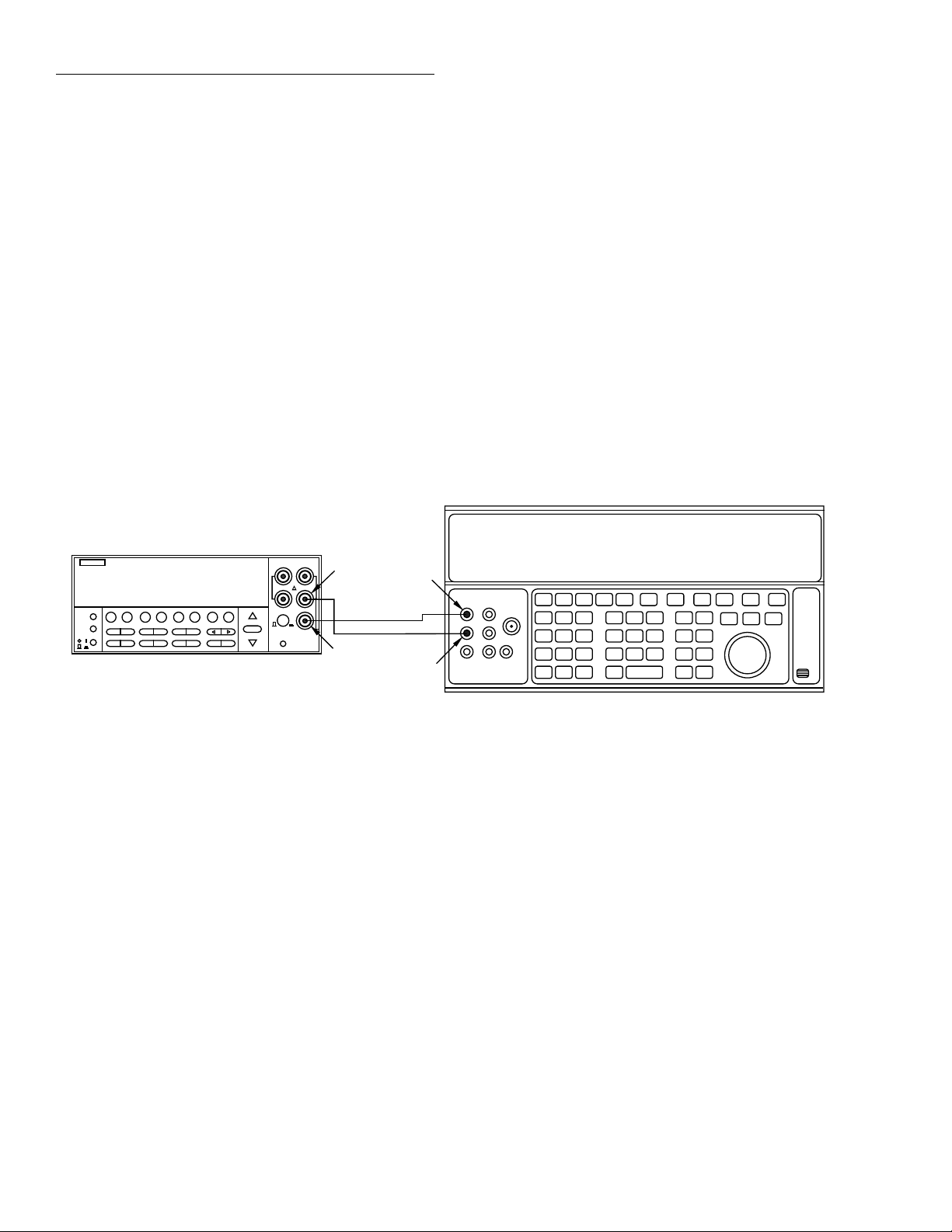
1. Connect the Model 2002 to the calibrator, as shown in
Figure 1-1. Be sure to connect calibrator HI to Model
2002 INPUT HI and calibrator LO to Model 2002
INPUT LO as shown.
NOTE
Use shielded, low-thermal connections
when testing the 200mV and 2V ranges to
avoid errors caused by noise or thermal
offsets. Connect the shield to calibrator
output LO.
If the Model 2002 is out of specifications and not under warranty, refer to the calibration procedures in Section 2.
WARNING
The maximum common-mode voltage
(voltage between INPUT LO and chassis ground) is 500V peak. Exceeding this
value may cause a breakdown in insulation, creating a shock hazard. Some of
the procedures in this section may
expose you to dangerous voltages. Use
standard safety precautions when such
dangerous voltages are encountered to
avoid personal injury caused by electric
shock.
NOTE
Do not connect test equipment to the
Model 2002 through a scanner or other
switching equipment.
2. Turn on the Model 2002 and the calibrator, and allow
a four-hour warm-up period before making
measurements.
3. Restore Model 2002 factory default conditions, as
explained in paragraph 1.7.
4. Set Model 2002 operating modes as follows:
A. From normal display, press CONFIG then DCV.
B. Select SPEED, then press ENTER.
C. Select HIACCURACY, then press ENTER.
D. Select FILTER, then press ENTER.
E. Select AVERAGING, then press ENTER.
F. Using the cursor and range keys, set the averaging
parameter to 10 readings, then press ENTER.
G. Press EXIT to return to normal display.
5. Select the Model 2002 200mV DC range. (If the FILT
annunciator is off, press the FILTER key to enable the
filter.)
NOTE
Do not use auto-ranging for any of the verification tests because auto-range hysteresis may cause the Model 2002 to be on an
incorrect range.
1-4
Page 16
Performance Verification
6. Set the calibrator output to 0.00000mVDC, and allow
the reading to settle.
7. Enable the Model 2002 REL mode. Leave REL enabled
for the remainder of the DC volts verification test.
8. Set the calibrator output to +190.00000mVDC, and
allow the reading to settle.
9. Verify that the Model 2002 reading is within the limits
summarized in Table 1-2.
10. Repeat steps 8 and 9 for the remaining ranges and voltages listed in Table 1-2.
11. Repeat the procedure for each of the ranges with negative voltages of the same magnitude as those listed in
Table 1-2.
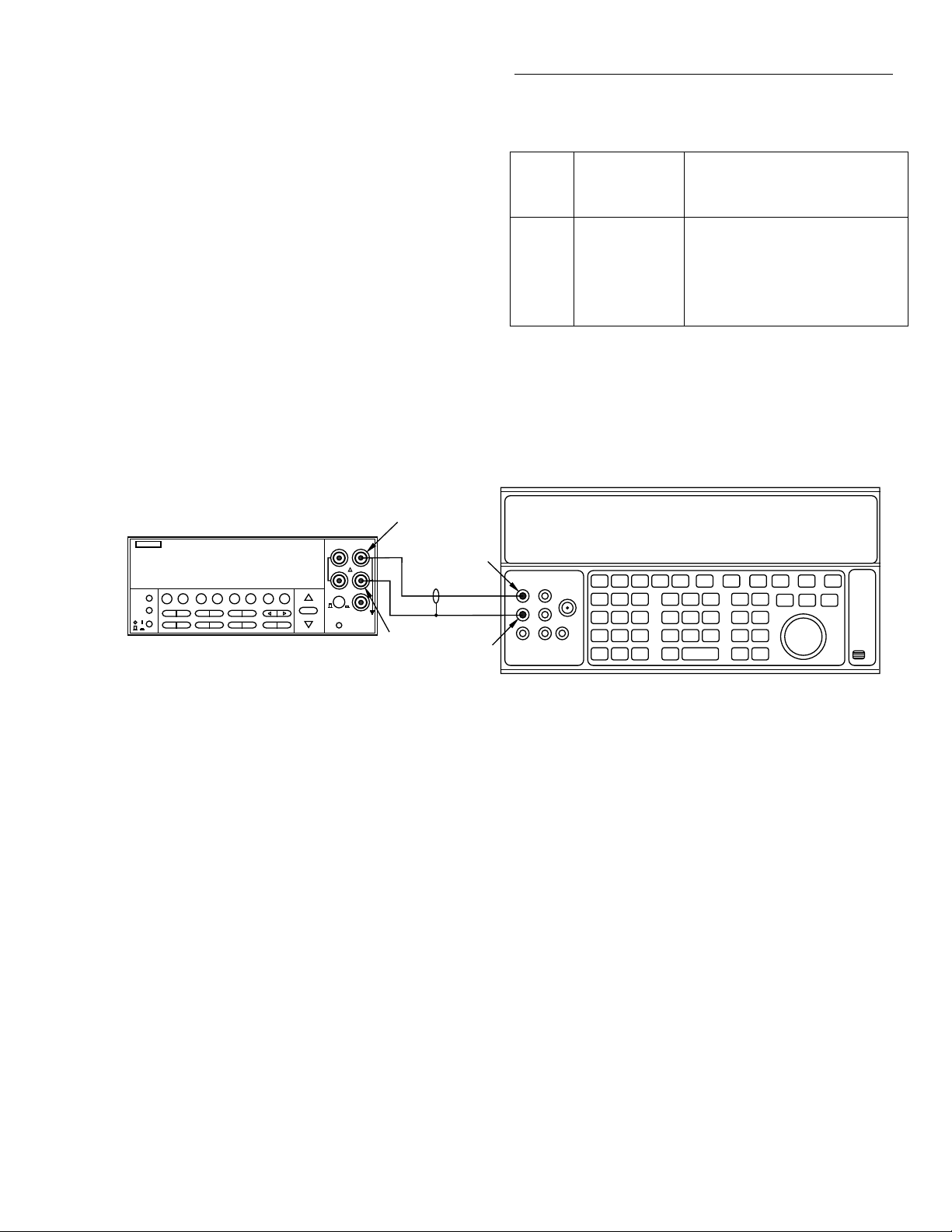
Input HI
Model 2002
Output HI
Table 1-2
Limits for DCV verification
2002
DCV
Range
Applied DC
Voltage
Reading Limits
(1 year, 18° to 28°C)
200mV 190.000000mV 189.991911mV to 190.008089mV
2V 1.90000000V 1.89996058 to 1.90003942V
20V 19.0000000V 18.9996550V to 19.0003450V
200V 190.000000V 189.993691V to 190.006309V
1000V 1000.0000V 999.94640V to 1000.05360V
NOTES:
1. Repeat procedure for negative voltages of same magnitude.
2. Reading limits shown include total absolute uncertainty of recommended
calibrator (see Table 1-1) and factory calibration uncertainty (see
specifications).
5700A Calibrator (Output DC Voltage)
2002 MULTIMETER
Figure 1-1
Connections for DC volts verification
Input
LO
Note : Use shielded, low-thermal cables
when testing 200mV and 2V ranges.
Output
LO
1-5
Page 17

Performance Verification
1.8.2 AC volts verification
AC voltage accuracy is checked by applying accurate AC
voltages at specific frequencies from an AC calibration
source and then verifying that each Model 2002 AC voltage
reading falls within the specified range. The two ACV verification procedures that follow include:
• Normal Mode
• Low-frequency Mode
CAUTION
Do not exceed 1100V peak between INPUT HI and INPUT LO, or 2 ×
7
10
V•Hz input, or instrument damage
may occur.
Normal mode
1. Turn on the Model 2002, calibrator, and amplifier, and
allow a one-hour warm-up period before making
measurements.
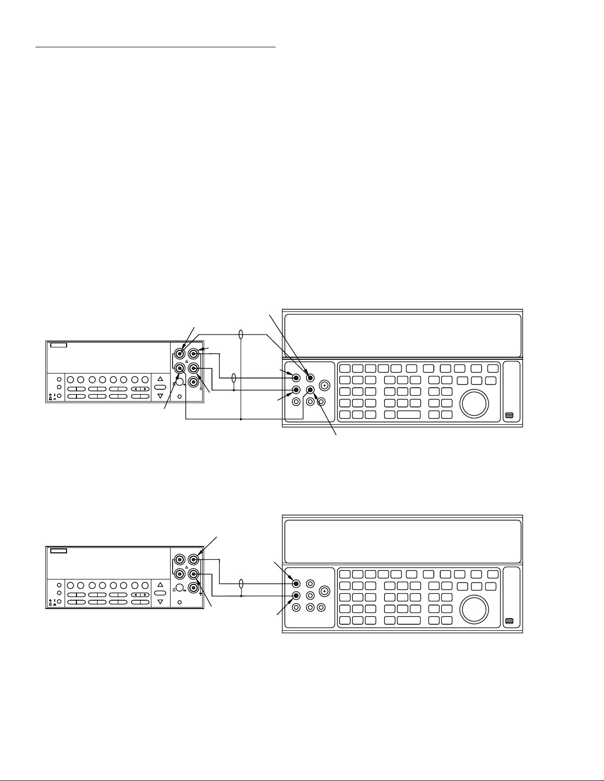
2. Connect the Model 2002 to the calibrator, as shown in
Figure 1-2. Be sure to connect amplifier HI to Model
2002 INPUT HI and amplifier LO to Model 2002
INPUT LO as shown. Connect the power amplifier to
the calibrator using the appropriate connector on the
rear of the calibrator.
3. Restore Model 2002 factory default conditions, as explained in paragraph 1.7.
4. Select the ACV function and the 200mV range on the
Model 2002, and make sure that REL is disabled.
NOTE
Do not use REL to null offsets when performing AC volts tests. Also, do not enable
the filter.
5. Set the calibrator output to 190.000mVAC at a frequency of 100Hz, and allow the reading to settle.
6. Verify that the Model 2002 reading is within the limits
summarized in Table 1-3.
7. Repeat steps 5 and 6 for 190mVAC at the remaining frequencies listed in Table 1-3 (except 2MHz). Verify that
instrument readings fall within the required limits listed
in the table.
8. Repeat steps 5 through 7 for the 2V, 20V, 200V, and
750VAC ranges using the input voltages and limits
stated in Table 1-3.
9. Connect the Model 2002 to the wideband calibrator output (see Figure 1-3).
10. Set the calibrator output to 190.000mV at a frequency of
2MHz.
11. Verify that the reading is within the limits shown in
Table 1-3.
12. Repeat steps 10 and 11 for 1.90000V input on the 2V
range.
CAUTION
Do not attempt to test the 20V–1000V
ranges at 2MHz.
1-6
Page 18
Performance Verification
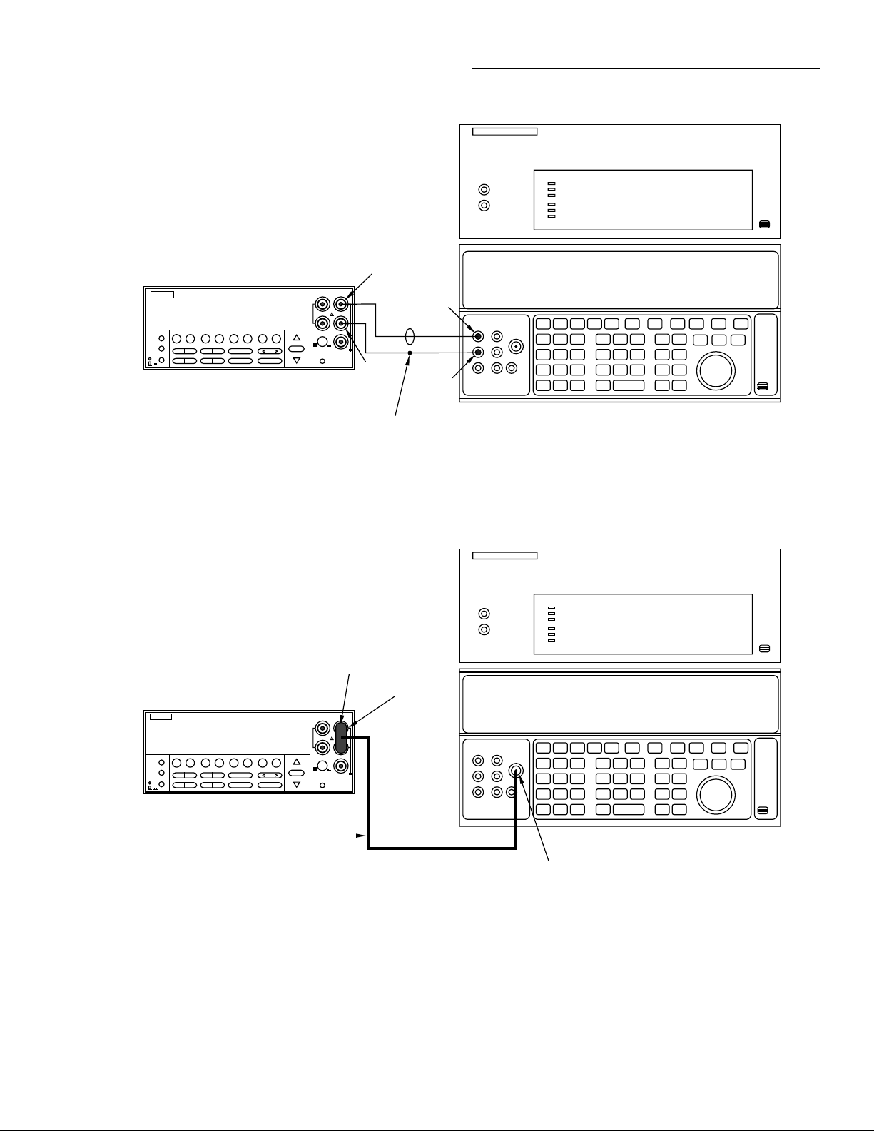
5725 Amplifier (Connect to calibrator)
Model 2002
1.90000 VAC RMS
2001 MULTIMETER
Input HI
Output HI
Input
LO
CA-18-1 Low-
capacitance cable
Figure 1-2
Connections for AC volts verification (all except 2MHz)
BNC to dual
banana
50Ω
terminator
Model 2002
Output
LO
5700A Calibrator (Output AC Voltage)
5725 Amplifier (Connect to calibrator)
1.90000 VAC RMS
2002 MULTIMETER
50Ω Coax
Figure 1-3
Connections for 2MHz AC volts verification
5700A Calibrator (Output AC Voltage)
Wideband
output
1-7
Page 19

Performance Verification
Table 1-3
Limits for normal mode AC voltage verification
*
180.100mVto199.900mV
186.000mVto194.000mV
1.80100Vto1.99900V
1.86000Vto1.94000V
18.2000Vto19.8000V
***
188.525mVto191.475mV
1.88525Vto1.91475V
18.8525Vto19.1475V
to
190.607V
189.393V
189.830Vto190.170V
189.868Vto190.132V
*****
748.87Vto751.13V
190.115mV
1.89400Vto1.90600V
to
1.89885V
1.89933Vto1.90068V
189.400mVto190.600mV
to
189.885mV
Reading limits (1 year, 18°C to 28°C)
189.933mVto190.068mV
1.90115V
18.9400Vto19.0600V
18.9837Vto19.0163V
18.9875Vto19.0125V
1-8
2002
Applied
ACV
100Hz 1kHz 5kHz 25kHz 50kHz 100kHz 200kHz 1MHz 2MHz
voltage
range
189.942mVto190.058mV
189.942mVto190.058mV
to
200mV 190.000mV 189.914mV
190.087mV
1.89942Vto1.90058V
1.89942Vto1.90058V
to
1.90087V
2V 1.90000V 1.89914V
18.9894Vto19.0106V
18.9913Vto19.0087V
to
19.0116V
20V 19.0000V 18.9885V
to
190.113V
189.887V
189.906Vto190.094V
to
190.122V
200V 190.000V 189.878V
749.02Vto750.98V
749.09Vto750.91V
V•Hz input.
to
7
751.02V
750V 750.00V 748.98V
** CAUTION: Do not exceed 2 × 10
** Use wideband option and connections for 2MHz tests.
NOTE: Reading limits shown include total absolute uncertainty of recommended calibrator (see Table 1-1). Reading limits also include the adder for AC Coupling of the input.
Page 20

Performance Verification
Table 1-4
Limits for low-frequency mode AC voltage verification
2002 ACV
range
Applied
voltage
Reading limits (1 year, 18°C to 28°C)
10Hz 50Hz 100Hz
200mV 190.000mV 189.837mV
to
190.163mV
189.904mV
to
190.097mV
189.923mV
to
190.077mV
2V 1.90000V 1.89875V
to
1.90125V
1.89923V
to
1.90078V
1.89942V
to
1.90058V
20V 19.0000V 18.9837V
to
19.0163V
18.9904V
to
19.0097V
18.9913V
to
19.0087V
200V 190.000V 189.849V
to
190.151V
189.906V
to
190.094V
189.906V
to
190.094V
750V 750.00V * 749.09V
to
750.91V
749.09V
to
750.91V
* Recommended calibrator/amplifier cannot source this voltage/frequency.
Notes:
1. Specifications above 100Hz are the same as normal mode.
2. Limits shown include total absolute uncertainty of recommended calibrator (see Table 1-1).
Low-frequency mode
1. Turn on the Model 2002, calibrator, and amplifier, and
allow a one-hour warm-up period before making
measurements.
2. Connect the Model 2002 to the calibrator, as shown in
Figure 1-2. Be sure to connect the amplifier HI to Model
2002 INPUT HI and amplifier LO to Model 2002
INPUT LO as shown. Connect the power amplifier to
the calibrator using the appropriate connector on the
rear of the calibrator.
3. Restore Model 2002 factory default conditions, as
explained in paragraph 1.7.
4. Select the ACV function and the 200mV range on the
Model 2002, and make sure that REL is disabled.
NOTE
Do not use REL to null offsets when performing AC volts tests. Also, do not enable
the filter.
5. Select the low-frequency mode as follows:
A. Press CONFIG ACV, select AC-TYPE, then press
ENTER.
B. Select LOW-FREQ-RMS, then press ENTER.
C. Press EXIT as required to return to normal display.
6. Set the calibrator output to 190.000mVAC at a frequency of 10Hz, and allow the reading to settle.
7. Verify that the Model 2002 reading is within the limits
summarized in Table 1-4.
8. Repeat steps 6 and 7 for 190mVAC at the remaining frequencies listed in the table.
9. Repeat steps 6 through 8 for the 2V, 20V, 200V, and
750VAC ranges, using the input voltages and limits
stated in Table 1-4.
1-9
Page 21

Performance Verification
AC peak mode
1. Turn on the Model 2002, calibrator, and amplifier, and
allow a one-hour warm-up period before making
measurements.
2. Connect the Model 2002 to the calibrator, as shown in
Figure 1-2. Be sure to connect the amplifier HI to Model
2002 INPUT HI, and the amplifier LO to MODEL 2002
INPUT LO as shown. Connect the power amplifier to
the calibrator using the appropriate connector on the
rear of the calibrator.
3. Restore the Model 2002 factory default conditions.
4. Select the ACV function and the 200mV range on the
Model 2002, and make sure that REL is disabled.
NOTE
Do not use REL to null offsets when performing AC volts tests. Use AC coupling
for 5kHz-1MHz tests. Use AC+DC coupling for 20Hz tests. (Use CONFIG-ACV
to set up coupling).
5. Select the AC peak and filter modes as follows:
A. Press CONFIG then ACV, select AC-TYPE, then
press ENTER.
B. Select PEAK, then press ENTER.
C. Select FILTER, then press ENTER.
D. Select AVERAGING, then press ENTER.
E. Using the cursor and range keys, set the averaging
parameter to 10 readings, then press ENTER.
F. Press EXIT as necessary to return to normal display.
G. If the FLT annunciator is off, press FILTER to
enable the filter.
6. Set the calibrator output to 100.000mVAC at a frequency of 5kHz, and allow the reading to settle.
7. Verify that the Model 2002 reading is within the limits
summarized in Table 1-5.
8. Repeat steps 6 and 7 for 100mVAC at the remaining frequencies listed in the table.
9. Repeat steps 6 through 8 for the 2V, 20V, 200V, and
750VAC ranges, using the input voltages and limits
stated in Table 1-6.
CAUTION
Do not apply more than 400V at 50kHz,
80V at 250kHz, 40V at 500kHz, or 20V
at 1MHz, or instrument damage may
occur.
10. Set input coupling to AC+DC, then repeat the procedure
for a 20Hz input signal.
Table 1-5
Limits for AC peak voltage verification
2002
ACV
range
200mV 100mV 139.9mV
2V 1V 1.407V
20V 10V 13.99V
200V 100V 140.7V
Applied
voltage*
20Hz† 5kHz 25kHz 50kHz 100kHz 250kHz 500kHz 750kHz 1MHz
139.9mV
to
142.9mV
to
142.9mV
1.407V
to
1.421V
to
1.421V
13.99V
to
14.30V
to
14.30V
140.7V
to
142.2V
to
142.2V
750V 500V — 701.3V
to
712.9V
** Calibrator voltage is given as an RMS value. Model 2002 reading limits are peak AC values.
** CAUTION: Do not apply more than 2 × 10
† Use AC+DC input coupling for 20Hz tests only. (Use CONFIG-ACV to set coupling.)
NOTE: Limits shown include uncertainty of recommended calibrator.
7
V•Hz.
Allowable readings (1 year, 18°C to 28°C)
139.9mV
to
143.0mV
1.407V
to
1.422V
13.98V
to
14.30V
140.6V
to
142.2V
701.0V
139.8mV
to
143.0mV
1.406V
to
1.422V
13.98V
to
14.31V
140.6V
to
142.3V
139.7mV
to
143.2mV
1.405V
to
1.424V
13.97V
to
14.32V
140.5V
to
142.4V
** ** ** ** ** **
to
713.2V
138.6mV
to
144.2mV
1.394V
to
1.434V
13.86V
to
14.42V
136.5mV
to
146.4mV
1.373V
to
1.456V
13.65V
to
14.64V
132.2mV
to
150.6mV
1.330V
to
1.498V
13.22V
to
15.06V
** ** ** **
127.3mV
to
155.5mV
1.281V
to
1.547V
12.73V
to
15.55V
1-10
Page 22
Performance Verification
1.8.3 DC current verification
DC current accuracy is checked by applying accurate DC
currents from a calibrator to the instrument AMPS input and
then verifying that the current readings fall within appropriate limits.
Follow the steps below to verify DCI measurement accuracy.
CAUTION
Do not apply more than 2A, 250V to the
AMPS input, or the amps protection
fuse will blow.
1. Connect the Model 2002 to the calibrator, as shown in
Figure 1-4. Be sure to connect calibrator HI to the
AMPS input, and connect calibrator LO to INPUT LO
as shown.
2. Turn on the Model 2002 and the calibrator, and allow a
one-hour warm-up period before making measurements. Be sure the calibrator is set for normal current
output.
3. Restore Model 2002 factory default conditions, as
explained in paragraph 1.7.
4. Set digital filter averaging as follows:
A. From normal display, press CONFIG then DCI.
B. Select FILTER, then press ENTER.
C. Select AVERAGING, then press ENTER.
D. Using the cursor and range keys, set the averaging
parameter to 10 readings, then press ENTER.
E. Press EXIT as necessary to return to normal display.
5. Select the DC current function (DCI) and the 200µA
range on the Model 2002. (If the FILT annunciator is off,
press the FILTER key to enable the filter.)
6. Set the calibrator output to +190.0000µADC, and allow
the reading to settle.
7. Verify that the Model 2002 reading is within the limits
summarized in Table 1-6.
8. Repeat steps 6 and 7 for the remaining ranges and currents listed in Table 1-6.
9. Repeat the procedure for each of the ranges with negative currents of the same magnitude as those listed in
Table 1-6.
Table 1-6
Limits for DC current verification
2002
DCI
range
Applied DC
current
Reading limits
(1 year, 18°C to 28°C)
200µA 190.0000µA 189.9010µA to 190.0990µA
2mA 1.900000mA 1.899114mA to 1.900886mA
20mA 19.00000mA 18.99085mA to 19.00915mA
200mA 190.0000mA 189.8816mA to 190.1184mA
2A 1.900000A 1.898108A to 1.901892A
NOTES:
1. Repeat procedure for negative currents.
2. Reading limits shown include total absolute uncertainty of recom-
mended calibrator (see Table 1-1) and factory calibration uncertainty
(see specifications).
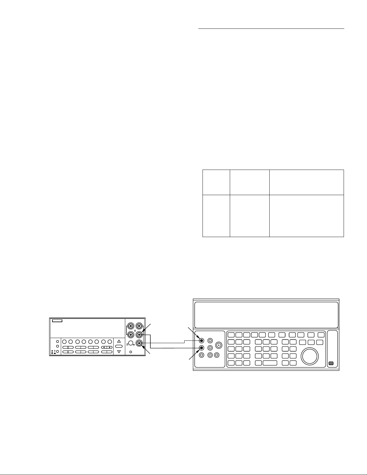
Model 2002
19.00000 mADC
2002 MULTIMETER
Figure 1-4
Connections for DC current verification
Input
LO
Amps
5700A Calibrator (Output DC Current)
Output HI
Output
LO
Note: Be sure calibrator is set for
normal current output.
1-11
Page 23
Performance Verification
1.8.4 AC current verification
AC current verification is performed by applying accurate
AC currents at specific frequencies and then verifying that
Model 2002 readings fall within specified limits.
Follow the steps below to verify ACI measurement accuracy.
CAUTION
Do not apply more than 2A, 250V to the
AMPS input, or the current protection
fuse will blow.
1. Connect the Model 2002 to the calibrator, as shown in
Figure 1-5. Be sure to connect calibrator HI to the
AMPS input, and connect calibrator LO to INPUT LO
as shown.
Model 2002
190.000 µAAC RMS
2002 MULTIMETER
Input
LO
Output HI
2. Turn on the Model 2002 and the calibrator, and allow a
one-hour warm-up period before making measurements. Be sure the calibrator is set for normal current
output.
3. Restore Model 2002 factory default conditions, as
explained in paragraph 1.7.
4. Select the AC current function and the 200µA range on
the Model 2002.
5. Set the calibrator output to 190.000µA AC at a frequency of 40Hz, and allow the reading to settle.
6. Verify that the Model 2002 reading is within the limits
for the present current and frequency summarized in
Table 1-7.
7. Repeat steps 5 and 6 for each frequency listed in Table
1-7.
8. Repeat steps 5 through 7 for the remaining ranges and
frequencies listed in Table 1-7.
5700A Calibrator (Output AC Current)
Figure 1-5
Connections for AC current verification
Amps
Output
LO
Note: Be sure calibrator is set for
normal current output.
1-12
Page 24

Table 1-7
Limits for AC current verification
Performance Verification
2002 ACI
range
200µA 190.000µA 188.260mV
2mA 1.90000mA 1.88355V
20mA 19.0000mA 18.8355V
200mA 190.000mA 188.355V
2A 1.90000A 1.88250V
NOTE: Reading limits shown include total absolute uncertainty of recommended calibrator (see Table 1-1).
Applied AC
current
40Hz 100Hz 1kHz 10kHz
to
191.740mV
to
1.91645V
to
19.1645V
to
191.645V
to
1.91750V
1.8.5 Resistance verification
Resistance verification is performed by connecting accurate
resistance values to the instrument and verifying that Model
2002 resistance readings are within stated limits.
Follow the steps below to verify resistance measurement
accuracy.
CAUTION
Do not apply more than 1100V peak
between INPUT HI and LO or more
than 150V peak between SENSE HI and
LO, or instrument damage may occur.
20Ω – 2M range verification
1. Using shielded 4-wire connections, connect the Model
2002 to the calibrator, as shown in Figure 1-6. Be sure
to connect calibrator HI and LO terminals to the Model
2002 HI and LO terminals (including SENSE HI and
LO) as shown.
2. Turn on the Model 2002 and the calibrator, and allow a
four-hour warm-up period before making
measurements.
3. Set the calibrator for 4-wire resistance (external sense
on).
4. Restore Model 2002 factory default conditions, as
explained in paragraph 1.7.
Reading limits (1 year, 18°C to 28°C)
189.562mV
to
190.439mV
1.89657V
to
1.90344V
18.9657V
to
19.0344V
189.657V
to
190.344V
1.89552V
to
1.90449V
5. Set Model 2002 operating modes as follows:
A. From normal display, press CONFIG then Ω4.
B. Select SPEED, then press ENTER.
C. Select HIACCURACY, then press ENTER.
D. Select FILTER, then press ENTER.
E. Select AVERAGING, then press ENTER.
F. Using the cursor and range keys, set the averaging
parameter to 10 readings, then press ENTER.
G. Select OFFSETCOMP, then press ENTER.
H. Select ON, then press ENTER. (Note that OFFSET-
COMP cannot be used with the 200kΩ and 2MΩ
ranges.)
I. Press EXIT to return to normal display.
6. Select the Ω4 function, and place the instrument on the
20Ω range. (If the FILT annunciator is off, press the
FILTER key to enable the filter.)
7. Set the calibrator to output 19Ω, and allow the reading
to settle. Verify that the reading is within the limits stated in Table 1-8.
Resistance values available in the Model
5700A calibrator may be slightly different
than the stated nominal resistance values.
Limits stated in Table 1-8 should be recalculated based on actual calibrator resistance values.
189.210mV
to
190.790mV
1.89742V
to
1.90258V
18.9742V
to
19.0258V
189.742V
to
190.258V
1.89390V
to
1.90610V
NOTE
189.020mV
to
190.980mV
1.89742V
to
1.90258V
18.9742V
to
19.0258V
189.685V
to
190.315V
1.89105V
to
1.90895V
1-13
Page 25
Performance Verification
8. Set the calibrator output to 190Ω, and allow the reading
to settle.
9. Verify that the reading is within the limits stated in Table
1-8. (NOTE: Recalculate limits if calibrator resistance is
not exactly as listed.)
10. Repeat steps 8 and 9 for the 2kΩ through 2MΩ ranges
using the values listed in Table 1-8. (Do not use offset
compensation for the 200kΩ and 2MΩ ranges.)
20MΩ and 200MΩ range verification
1. Connect the DC calibrator and Model 2002 using the 2wire connections shown in Figure 1-7.
2. Set the calibrator to the 2-wire mode (external sense
off).
3. Set Model 2002 operating modes as follows:
Sense HI
Sense HI
Model 2002
Input HI
1.90000000 kΩ OCmp
2002 MULTIMETER
Output HI
A. From normal display, press CONFIG then Ω2.
B. Select SPEED, then press ENTER.
C. Select HIACCURACY, then press ENTER.
D. Select FILTER, then press ENTER.
E. Select AVERAGING, then press ENTER.
F. Using the cursor and range keys, set the averaging
parameter to 10 readings, then press ENTER.
G. Press EXIT to return to normal display.
4. Select the Model 2002 Ω2 function, and change to the
20MΩ range. (If the FILT annunciator is off, press the
FILTER key to enable the filter.)
5. Set the calibrator to output 19MΩ, and allow the reading
to settle.
6. Verify that the reading is within the limits for the 20MΩ
range stated in Table 1-8. (NOTE: Recalculate limits if
actual calibrator resistance differs from value shown.)
7. Repeat steps 4 through 6 for the 200MΩ range (output
100MΩ).
5700A Calibrator (Output 4-wire Resistance)
Input
LO
Sense LO
Note : Use shielded cables to minimize noise.
Enable calibrator external sense mode.
Output
LO
Figure 1-6
Connections for resistance verification (20Ω-2MΩ ranges)
Model 2002
Input HI
19.0000000 MΩ
2002 MULTIMETER
Input
LO
Note: Use shielded cable to minimize noise.
Disable calibrator external sense mode.
Figure 1-7
Connections for resistance verification (20MΩ and 200MΩ ranges)
Output HI
Output
LO
Sense LO
5700A Calibrator (Output 2-Wire Resistance)
1-14
Page 26
Performance Verification
Table 1-8
Limits for resistance verification (20Ω-200MΩ ranges)
Nominal
2002 Ω
range
applied
resistance
Reading limits
(1 year, 18°C to 28°C)
20Ω 19Ω 18.9985025Ω to 19.0014975Ω
200Ω 190Ω 189.991277Ω to 190.008723Ω
2kΩ 1.9kΩ 1.89994714kΩ to 1.90005286kΩ
20kΩ 19kΩ 18.9994638kΩ to 19.0005362kΩ
200kΩ 190kΩ 189.989313kΩ to 190.010687kΩ
2MΩ 1.9MΩ 1.89981109MΩ to 1.90018891MΩ
20MΩ 19MΩ 18.9940619MΩ to 19.0059381MΩ
200MΩ 100MΩ 99.930910MΩ to 100.069090MΩ
Notes:
1. Limits shown include total absolute calibrator uncertainty (see Table
1-1) and factory calibration uncertainty (see specifications), and are
based on nominal calibration values shown. Recalculate limits using
Model 2002 relative accuracy specifications, factory calibration uncertainty, and calibrator absolute uncertainty if calibrator resistance values differ from nominal values shown.
2. Use 4-wire connections and function for 20Ω-2MΩ ranges. Use 2wire connections and function for 20MΩ and 200MΩ ranges.
1GΩ range verification
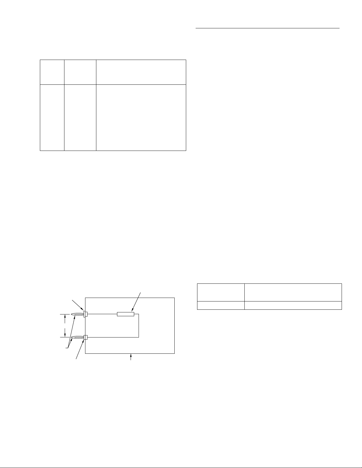
1. Mount the 1GΩ resistor and the banana plugs to the test
box, as shown in Figure 1-8. Be sure to mount the
banana plugs with the correct spacing. The resistor
should be completely enclosed in and shielded by the
metal test box. The resistor LO lead should be electrically connected to the test box to provide adequate
shielding.
1GΩ Resistor (Keithley
part # R-289-1G)
Insulated
Plug
HI
0.75"
LO
Banana
Plugs
Non-insulated Plug
Note: Resistor must be accurately characterized
before use (see text).
Metal
Test Box
Figure 1-8
1GΩ resistor test box construction
2. Characterize the 1GΩ resistor to within ±1,000ppm or
better using an accurate megohm bridge or similar
equipment. Record the characterized value where indicated in Table 1-9. Also compute the limits based on the
value of R using the formula at the bottom of the table.
NOTE
The actual value of the 1GΩ resistor
should not exceed 1.05GΩ.
3. Set Model 2002 operating modes as follows:
A. From normal display, press CONFIG then Ω2.
B. Select SPEED, then press ENTER.
C. Select HIACCURACY, then press ENTER.
D. Select FILTER, then press ENTER.
E. Select AVERAGING, then press ENTER.
F. Using the cursor and range keys, set the averaging
parameter to 10 readings, then press ENTER.
G. Press EXIT to return to normal display.
4. Select the 2-wire ohms function (Ω2) and the 1GΩ
range on the Model 2002. (If the FILT annunciator is off,
press the FILTER key to enable the filter.)
5. Connect the 1GΩ resistor test box (from steps 1 and 2)
to the INPUT HI and LO terminals of the Model 2002.
(Be sure that the box shield is connected to INPUT LO.)
Allow the reading to settle.
6. Verify that the Model 2002 reading is within the limits
you calculated and recorded in Table 1-9.
Table 1-9
Limits for resistance verification (1GΩ range)
Characterized
resistor (R)
Reading limits
(1 year, 18°C to 28°C)
_________ GΩ _________ GΩ to _________ GΩ
* 1 year limits = R ± (0.002065R + 15,000)Ω
Where R = characterized value of 1GΩ resistor in ohms.
1.8.6 Frequency accuracy verification
Frequency accuracy verification is performed by connecting
an accurate frequency source to Model 2002 inputs, and then
verifying that the frequency readings are within stated limits.
Use the procedure below to verify the frequency measurement accuracy of the Model 2002.
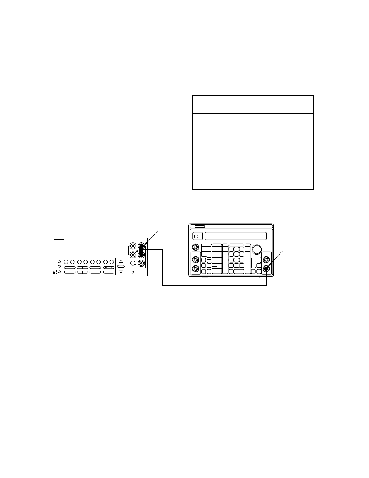
1. Connect the frequency synthesizer to the Model 2002
INPUT terminals, as shown in Figure 1-9.
2. Turn on both instruments, and allow a one-hour warmup period before measurement.
1-15
Page 27
Performance Verification
3. Set the synthesizer operating modes as follows:
FREQ: 1Hz
AMPTD: 5V p-p
OFFSET: 0V
MODE: CONT
FCTN: sine
4. Restore Model 2002 factory defaults, as explained in
paragraph 1.7.
5. Set maximum signal level to 10V as follows:
A. Press CONFIG then FREQ.
B. Select MAX-SIGNAL-LEVEL, then press ENTER.
C. Choose 10V, then press ENTER.
D. Press EXIT to return to normal display.
6. Press the FREQ key to select the frequency function.
7. Verify that the Model 2002 frequency reading is within
the limits shown in the first line of Table 1-10.
BNC-to-Dual
Banana Plug
Model 2002
1.0000 MHz
Adapter
8. Set the synthesizer to each of the frequencies listed in
Table 1-10, and verify that the Model 2002 frequency
reading is within the required limits.
Table 1-10
Frequency verification limits
Synthesizer
frequency
Reading limits
(1 year, 18°C to 28°C)
1Hz 0.9997Hz to 1.0003Hz
10Hz 9.9970Hz to 10.003Hz
100Hz 99.970Hz to 100.03Hz
1kHz 0.9997kHz to 1.0003kHz
10kHz 9.9970kHz to 10.003kHz
100kHz 99.970kHz to 100.03kHz
1MHz 0.9997MHz to 1.0003MHz
10MHz 9.9970MHz to 10.003MHz
15MHz 14.996MHz to 15.004MHz
Model 3930A or 3940 Synthesizer
Main
Function
Output
Figure 1-9
Connections for frequency accuracy verification
1-16
50Ω BNC Coaxial Cable
Page 28

Performance Verification
1.8.7 Temperature reading checks
When using thermocouples, the Model 2002 displays temperature by measuring the DC thermocouple voltage, and
then calculating the corresponding temperature. Similarly,
the instrument computes RTD temperature readings by measuring the resistance of the RTD probe and calculating temperature from the resistance value.
Since the instrument computes temperature from DCV and
resistance measurements, verifying the accuracy of those
DCV and resistance measurement functions guarantees the
accuracy of corresponding temperature measurements.
Thus, it is not necessary to perform a comprehensive temperature verification procedure if DCV and resistance verification procedures show the instrument meets its specifications
in those areas. However, those who wish to verify that the
Model 2002 does in fact properly display temperature can
use the following procedure to do so.
Selecting the temperature sensor
Follow the steps below to select the type of temperature
sensor:
1. From normal display, press CONFIG then TEMP.
2. Select SENSOR, then press ENTER.
3. Select 4-WIRE-RTD or THERMOCOUPLE as desired,
then press ENTER.
4. Select the type of RTD probe or thermocouple you wish
to test, then return to the CONFIG TEMPERATURE
menu.
5. Select UNITS, then press ENTER.
6. Select DEG-C, then press ENTER.
7. Press EXIT as necessary to return to normal display.
8. Press the TEMP key to place the Model 2002 in the temperature display mode. Refer to further information
below on how to check thermocouple and RTD probe
readings.
Thermocouple temperature reading checks
To check thermocouple readings, simply apply the appropriate DC voltage listed in Table 1-11 to the Model 2002 INPUT
jacks using a precision DC voltage source (such as the one
used to verify DC voltage accuracy in paragraph 1.8.1), and
check the displayed temperature reading. Be sure to use lowthermal cables for connections between the DC calibrator
and the Model 2002 when making these tests.
NOTE
The voltages shown are based on a 0°C
reference junction temperature. Use the
CONFIG-TEMP menu to set the default
reference junction temperature to 0°C.
Table 1-11
Thermocouple temperature reading checks
Reading limits
Thermocouple
type
J -7.659mV
K -5.730mV
T -5.439mV
E -8.561mV
R 0.054mV
S 0.055mV
B 0.632mV
* Voltages shown are based on ITS-90 standard using 0°C reference
junction temperature. Use CONFIG-TEMP menu to set default reference
junction to 0°C.
NOTE: Reading limits shown do not include DCV calibrator uncertainty.
Applied DC
voltage*
0mV
1.277mV
5.269mV
42.280mV
0mV
1.000mV
4.096mV
54.138mV
0mV
0.992mV
4.278mV
20.255mV
0mV
1.495mV
6.319mV
75.621mV
0.647mV
4.471mV
20.877mV
0.646mV
4.233mV
18.503mV
1.241mV
4.834mV
13.591mV
(°C) 1 year,
18°C to 28°C
-190.5 to -189.5
-0.5 to +0.5
24.5 to 25.5
99.5 to 100.5
749.5 to 750.0
-190.5 to -189.5
-0.5 to +0.5
24.5 to 25.5
99.5 to 100.5
1349.5 to 1350.5
-190.5 to -189.5
-0.5 to +0.5
24.5 to 25.5
99.5 to 100.5
389.5 to 390.5
-190.6 to -189.4
-0.6 to +0.6
24.4 to 25.6
99.4 to 100.6
989.4 to 990.6
7 to 13
97 to 103
497 to 503
1747 to 1753
7 to 13
97 to 103
497 to 503
1747 to 1753
355 to 365
495 to 505
995 to 1005
1795 to 1805
1-17
Page 29

Performance Verification
RTD temperature reading checks
Use a precision decade resistance box (see Table 1-1) to simulate probe resistances at various temperatures (Table 1-12).
Be sure to use 4-wire connections between the decade resistance box and the Model 2002.
Table 1-12
RTD probe temperature reading checks
Reading limits
RTD probe
type
PT385
(α=0.00385)
PT392
(α=0.00392)
NOTE: Reading limits shown do not include uncertainty of resistance
standards.
Applied
resistance
22.80Ω
60.25Ω
100Ω
109.73Ω
138.50Ω
313.59Ω
63.68Ω
100Ω
109.90Ω
139.16Ω
266.94Ω
(°C) 1 year,
18°C to 28°C
-190.068 to -189.932
-100.021 to -99.979
-0.021 to +0.021
24.979 to 25.021
99.979 to 100.021
599.932 to 600.068
-90.021 to -89.979
-0.021 to +0.021
24.979 to 25.021
99.979 to 100.021
449.932 to 450.068
1-18
Page 30

2
Calibration
2.1 Introduction
This section gives detailed procedures for calibrating the
Model 2002. Basically, there are three types of calibration
procedures:
• Comprehensive calibration
• AC self-calibration
• Low-level calibration
Comprehensive calibration requires accurate calibration
equipment to supply precise DC voltages, DC currents, and
resistance values. AC self-calibration requires no external
equipment and can be performed at any time by the operator.
Low-level calibration is normally performed only at the factory when the instrument is manufactured and is not usually
required in the field.
NOTE
Low-level calibration is required in the
field only if the Model 2002 has been
repaired, or if the other calibration procedures cannot bring the instrument within
stated specifications.
A single-point calibration feature is also available to allow
the user to calibrate a single function or range without having
to perform the entire calibration procedure.
Section 2 includes the following information:
2.2 Environmental conditions: States the temperature
and humidity limits for calibration.
2.3 Warm-up period: Discusses the length of time the
Model 2002 should be allowed to warm up before
calibration.
2.4 Line power: States the power line voltage limits when
calibrating the unit.
2.5 Calibration lock: Explains how to unlock calibration
with the CAL switch.
2.6 IEEE-488 bus calibration commands: Summarizes
bus commands used for calibration, lists a simple calibration program, and also discusses other important
aspects of calibrating the instrument over the bus.
2.7 Calibration errors: Details front panel error messages
that might occur during calibration and also explains
how to check for errors over the bus.
2.8 Comprehensive calibration: Covers comprehensive
(user) calibration from the front panel and over the
IEEE-488 bus.
2.9 AC self-calibration: Discusses the AC user calibra-
tion process, both from the front panel and over the
IEEE-488 bus.
2.10 Low-level calibration: Explains how to perform the
low-level calibration procedure, which is normally
required only at the factory.
2.11 Single-point calibration: Outlines the basic methods
for calibrating only a single function or range instead
of having to go through the entire calibration
procedure.
2-1
Page 31

Calibration
2.2 Environmental conditions
Calibration procedures should be performed at an ambient
temperature of 23° ± 5°C, and at a relative humidity of less
than 80% unless otherwise noted.
NOTE
If the instrument is normally used over a
different ambient temperature range, calibrate the instrument at the center of that
temperature range.
If the internal temperature of the Model 2002 drifts excessively during calibration, an error will be generated. See
Appendix C for additional information.
2.3 Warm-up period
The Model 2002 must be allowed to warm up for at least four
hours before calibration. If the instrument has been subjected
to temperature extremes (outside the range stated in paragraph 2.2), allow additional time for internal temperatures to
stabilize. Typically, it takes one additional hour to stabilize a
unit that is 10°C (18°F) outside the specified temperature
range.
NOTE
Placement of the OPTION SLOT cover
affects the internal temperature of the
Model 2002. To achieve T
ifications, the OPTION SLOT cover must
be in the same position (on or off) as when
the Model 2002 is to be used.
The calibration equipment should also be allowed to warm
up for the minimum period specified by the manufacturer.
± 1°C spec-
CAL
2.4 Line power
The Model 2002 should be calibrated while operating from
a line voltage in the range of 90-134V or 180-250V at 50, 60,
or 400Hz.
If you attempt comprehensive or low-level calibration without performing the unlocking procedure, the following message will be displayed:
CALIBRATION LOCKED
Press the CAL switch to unlock.
Note that it is not necessary to unlock calibration for the AConly self-calibration procedure. Also, IEEE-488 bus calibration command queries such as the :DATE and :DATA commands are not protected by the calibration lock.
2.5.2 Low-level calibration lock
To unlock low-level calibration, press in and hold the CAL
switch while turning on the power. Low-level calibration can
then be performed.
NOTE
Do not unlock low-level calibration unless
you have the appropriate equipment and
intend to perform low-level calibration.
See paragraph 2.10 for low-level calibration details.
2.5.3 IEEE-488 bus calibration lock status
You can determine the status of either calibration lock over
the bus by using the appropriate query. To determine comprehensive calibration lock status, send the following query:
:CAL:PROT:SWIT?
The instrument will respond with the calibration lock status:
0: comprehensive calibration locked
1: comprehensive calibration unlocked
To determine the status of the low-level calibration lock,
send the following query:
:CAL:PROT:LLEV:SWIT?
Responses to this calibration lock query include:
0: low-level calibration locked
1: low-level calibration unlocked
2.5 Calibration lock
2.5.1 Comprehensive calibration lock
Before performing comprehensive calibration, you must first
unlock calibration by momentarily pressing in on the
recessed CAL switch. The instrument will display the following message:
CALIBRATION UNLOCKED
Calibration can now be performed
2-2
Refer to paragraph 2.6 below and Section 3 for more details
on calibration commands.
2.6 IEEE-488 bus calibration commands
Table 2-1 summarizes calibration commands used to calibrate the instrument over the IEEE-488 bus (GPIB).
Page 32

Table 2-1
IEEE-488 bus calibration command summary
Command Description
:CALibration
:PROTected
:INITiate
:LOCK
:SWITch?
:SAVE
:DATA?
:DATE <yr>, <mon>, <day>
:DATE?
:NDUE <yr>, <mon>, <day>
:NDUE?
:DC
:ZERO
:V2 <NRf>
:V20 <NRf>
:OHM1M <NRf>
:OHM200K <NRf>
:OHM20K <NRf>
:OHM2K <NRf>
:OHM200 <NRf>
:OHM20 <NRf>
:A200U <NRf>
:A2M <NRf>
:A20M <NRf>
:A200M <NRf>
:A2 <NRf>
:OPEN
:LLEVel
:SWITch?
Calibration root command.
All commands in this subsystem are protected by the CAL switch (except queries).
Initiate calibration.
Lock out calibration (opposite of enabling cal with CAL switch).
Request comprehensive CAL switch state. (0 = locked; 1 = unlocked)
Save cal constants to EEROM.
Download cal constants from 2002.
Send cal date to 2002.
Request cal date from 2002.
Send next due cal date to 2002.
Request next due cal date from 2002.
Comprehensive calibration subsystem.
Short-circuit calibration step.
+2V DC calibration step.
+20V DC calibration step.
1MΩ calibration step.
200kΩ calibration step.
20kΩ calibration step.
2kΩ calibration step.
200Ω calibration step.
20Ω calibration step.
200µA DC calibration step.
2mA DC calibration step.
20mA DC calibration step.
200mA DC calibration step.
2A DC calibration step.
Open circuit calibration step.
Low-level calibration subsystem.
Request low-level CAL switch state. (0 = locked; 1 = unlocked)
:STEP <Step #>
1
2
3
4
5
6
7
8
9
10
11
12
13
:UNPRotected
:ACCompensation
NOTE: Upper-case letters indicate short form of each command. For example, instead of sending ":CALibration:PROTected:INITiate", send
":CAL:PROT:INIT".
20V AC at 1kHz step.
20V AC at 30kHz step.
200V AC at 1kHz step.
200V AC at 30kHz
1.5V AC at 1kHz step.
200mV AC at 1kHz step.
5mV AC at 100kHz step.
0.5mV AC at 1kHz step.
+100V DC step.
-20V DC step.
Rear inputs short-circuit step.
20mA AC at 1kHz step.
2V AC at 1Hz step.
Commands in this subsystem not protected by CAL switch.
Perform user AC calibration (disconnect all cables)
Calibration
2-3
Page 33

Calibration
2.7 Calibration errors
The Model 2002 checks for errors after each calibration step,
minimizing the possibility that improper calibration may
occur due to operator error. The following paragraphs discuss both front panel and bus error reporting.
2.7.1 Front panel error reporting
If an error is detected during comprehensive calibration, the
instrument will display an appropriate error message (see
Appendix C).
2.7.2 IEEE-488 bus error reporting
You can detect errors over the bus by testing the state of EAV
(Error Available) bit (bit 2) in the status byte. (Use the *STB?
query or serial polling to request the status byte.) If you wish
to generate an SRQ (Service Request) on errors, send "*SRE
4" to the instrument to enable SRQ on errors.
You can query the instrument for the type of error by using
the ":SYSTem:ERRor?" query. The Model 2002 will respond with the error number and a text message describing
the nature of the error. Appendix C summarizes calibration
errors.
2.8.1 Recommended equipment for
comprehensive calibration
Table 2-2 lists all test equipment recommended for comprehensive calibration. Alternate equipment (such as a DC
transfer standard and characterized resistors) may be used as
long as that equipment has specifications at least as good as
those listed in the table.
Table 2-2
Recommended equipment for comprehensive calibration
Mfg. Model Description Specifications*
Fluke 5700A Calibrator ±5ppm basic
uncertainty.
DC Voltage:
2V: ±7ppm
20V: ±5ppm
Resistance:
19Ω: ±26ppm
190Ω: ±17ppm
1.9kΩ: ±11ppm
19kΩ: ±11ppm
100kΩ: ±13ppm
1MΩ: ±18ppm
2.8 Comprehensive calibration
The comprehensive calibration procedure calibrates the
DCV, DCI, and ohms functions. At the end of the front panel
calibration procedure, AC self-calibration is also performed
to complete the calibration process.
Comprehensive calibration should be performed at least
once a year, or every 90 days to ensure the unit meets the corresponding specifications.
The comprehensive calibration procedure covered in this
paragraph is normally the only calibration required in the
field. However, if the unit has been repaired, you should perform the low-level calibration procedure explained in paragraph 2.10.
DC Current:
200µA: ±100ppm
2mA: ±55ppm
20mA: ±55ppm
200mA: ±65ppm
1A: ±110ppm
Keithley 8610 Low-thermal
shorting plug
* 90-day calibrator specifications shown include total uncertainty at specified output.
2.8.2 Front panel comprehensive calibration
Follow the steps below to calibrate the Model 2002 from the
front panel. Refer to paragraph 2.8.3 below for the procedure
to calibrate the unit over the IEEE-488 bus. Table 2-3 summarizes the front panel calibration procedure.
2-4
Page 34

Calibration
Figure 2-1
Low-thermal short connections
Model 2002
S+ HI
LOS-
Model 8610
Low-thermal
short
Table 2-3
Front panel comprehensive calibration summary
Equipment/
Step Description
1
Warm-up, unlock calibration
2
DC Zero calibration
3
+2V DC calibration
4
+20V DC calibration
5
1MΩ calibration
6
200kΩ calibration
7
20kΩ calibration
8
2kΩ calibration
9
200Ω calibration
10
20Ω calibration
11
200µA DC calibration
12
2mA DC calibration
13
20mA DC calibration
14
200mA DC calibration
15
2A DC calibration
16
Open-circuit calibration
17
AC self-calibration
18
Enter calibration dates
19
Save calibration constants
connections
None
Low-thermal short
DCV calibrator
DCV calibrator
Ohms calibrator
Ohms calibrator
Ohms calibrator
Ohms calibrator
Ohms calibrator
Ohms calibrator
DCA calibrator
DCA calibrator
DCA calibrator
DCA calibrator
DCA calibrator
Disconnect leads
Disconnect leads
None
None
2. Connect the Model 8610 low-thermal short to the instrument INPUT and SENSE terminals, as shown in Figure
2-1. Wait at least three minutes before proceeding to
allow for thermal equilibrium.
NOTE
Be sure to connect the low-thermal short
properly to the HI, LO, and SENSE terminals. Keep drafts away from low-thermal
connections to avoid thermal drift, which
could affect calibration accuracy.
3. Press ENTER. The instrument will then begin DC zero
calibration. While calibration is in progress, the following will be displayed:
Performing Short Ckt Calibration
Procedure
Step 1: Prepare the Model 2002 for calibration
1. Turn on the power, and allow the Model 2002 to warm
up for at least four hours before performing calibration.
2. Unlock comprehensive calibration by briefly pressing in
on the recessed front panel CAL switch, and verify that
the following message is displayed:
CALIBRATION UNLOCKED
Calibration can now be performed
3. Enter the front panel calibration menu as follows:
A. From normal display, press MENU.
B. Select CALIBRATION, and press ENTER.
C. Select COMPREHENSIVE, then press ENTER.
4. At this point, the instrument will display the following
message:
DC CALIBRATION PHASE
Step 2: DC zero calibration
1. Press ENTER. The instrument will display the following prompt.
SHORT CIRCUIT INPUTS
Step 3: DC volts calibration
1. When the DC zero calibration step is completed, the following message will be displayed:
CONNECT 2 VDC
2. Disconnect the low-thermal short, and connect the DC
calibrator to the INPUT jacks, as shown in Figure 2-2.
NOTE
Although 4-wire connections are shown,
the sense leads are connected and disconnected at various points in the procedure
by turning calibrator external sense on or
off as appropriate. If your calibrator does
not have provisions for turning external
sense on and off, disconnect the sense
leads when external sensing is to be turned
off, and connect the sense leads when
external sensing is to be turned on.
2-5
Page 35

Calibration
3. Set the calibrator output to +2.000000V, and turn external sense off. Wait at least three minutes for thermal
equilibrium.
4. Press ENTER, and note that the Model 2002 displays
the presently selected calibration voltage:
INPUT = 2.00000000 V
(At this point, you can use the cursor and range keys to set
the calibration voltage to a value from 0.95 to 2.05V if your
calibrator cannot source 2V.)
NOTE
For best results, it is recommended that
you use the stated calibration values
throughout the procedure whenever
possible.
5. Press ENTER. The instrument will display the following during calibration:
Sense HI
Sense HI
Model 2002
Input HI
Performing 2 VDC Calibration
6. After completing 2VDC calibration, the instrument will
display the following:
CONNECT 20 VDC
7. Set the DC calibrator output to +20.000000V.
8. Press ENTER, and note that the instrument displays the
calibration voltage:
INPUT = 20.0000000
(At this point, you can use the cursor and range keys to set
the calibration voltage to a value from 9.5 to 20.5V if your
calibrator cannot source 20V.)
9. Press ENTER. The instrument will display the
following message to indicate it is performing 20V DC
calibration:
Performing 20 VDC Calibration
5700A Calibrator
Output HI
Input
LO
Sense LO
Note : Use shielded cables to minimize noise.
Enable or disable calibrator external
sense as indicated in procedure.
Output
LO
Sense LO
Figure 2-2
Calibrator connections for DC volts and ohms portion of comprehensive calibration
2-6
Page 36

Calibration
Step 5: Ohms calibration
1. After completing 20VDC calibration, the instrument
will display the following:
CONNECT 1 MΩ 4W
2. Set the calibrator output to 1.00000MΩ, and make sure
that external sense is turned on.
NOTE
Use external sensing (4-wire ohms) when
calibrating all resistance ranges. Be sure
that the calibrator external sense mode is
on.
3. Press ENTER, and note that the Model 2002 displays
the resistance calibration value:
INPUT = 1.0000000 MΩ
4. Using the cursor and range keys, set the resistance value
displayed by the Model 2002 to the exact resistance value displayed by the calibrator. (The allowable range is
from 475kΩ to 1.025MΩ.)
5. Press ENTER, and note that the instrument displays the
following during 1MΩ calibration:
Performing 1 MΩ Calibration
6. After completing 1MΩ calibration, the instrument will
display the following:
CONNECT 100 kΩ 4W
7. Set the calibrator output to 100kΩ, and make sure that
external sense is turned on.
8. Press ENTER, and note that the Model 2002 displays
the resistance calibration value:
INPUT = 100.00000 kΩ
9. Using the cursor and range keys, set the resistance value
displayed by the Model 2002 to the exact resistance value displayed by the calibrator. (The allowable range for
this parameter is from 95kΩ to 205kΩ.)
10. Press ENTER to complete the 200kΩ calibration step.
11. Repeat steps 7 through 10 for the 20kΩ, 2kΩ, 200Ω, and
20Ω ranges in that order. Be sure to set the calibrator to
the correct resistance value, and adjust the Model 2002
display to agree with the calibrator value.
Calibration
step
2MΩ
200kΩ
20kΩ
2kΩ
200Ω
20Ω
* Nominal values shown. Use exact calibrator value.
Calibration
value* Allowable range
1MΩ
100kΩ
19kΩ
1.9kΩ
190Ω
19Ω
475kΩ to 1.025MΩ
95kΩ to 205kΩ
9.5kΩ to 20.5kΩ
0.95kΩ to 2.05kΩ
95Ω to 205Ω
9.5Ω to 20.5Ω
Step 6: DC amps calibration
1. After ohms calibration is completed, the instrument will
prompt you for the first DC amps calibration step:
CONNECT 200 µADC
2. Connect the DC amps calibrator to the AMPS and
INPUT LO terminals (see Figure 2-3).
3. Set the calibrator output to 200.000µA, and make sure
the unit is in operate. (The allowable range is from 95µA
to 205µA.)
4. Be sure that the displayed current matches the calibration value, then press ENTER to complete this calibration step.
5. Repeat steps 3 and 4 for the remaining amps calibration
points as follows:
Calibration
step
200µA
2mA
20mA
200mA
2A
Calibration
current Allowable range
200.000µA
2.00000mA
20.0000mA
200.0000mA
1.00000A
95µA to 205µA
0.95mA to 2.05mA
9.5mA to 20.5mA
95mA to 205mA
0.95A to 2.05A
2-7
Page 37

Calibration
5700A Calibrator
Model 2002
2002 MULTIMETER
Input
LO
Amps
Output HI
Output
LO
Figure 2-3
Connections for amps comprehensive calibration
Step 7: Open-circuit calibration
1. At this point, the instrument will display the following
message advising you to disconnect test leads:
OPEN CIRCUIT INPUTS
2. Disconnect all test leads from the INPUT and AMPS
jacks, then press ENTER. During this calibration phase,
the instrument will display the following:
Performing Open Ckt Calibration
Step 8: AC self-calibration
1. After open-circuit calibration, the instrument will display the following message:
AC CALIBRATION PHASE
2. Make sure all test leads are still disconnected from the
Model 2002 INPUT and SENSE jacks.
3. Press ENTER to perform AC calibration, which will
take about six minutes to complete. During AC calibration, the instrument will display the following:
Calibrating AC: Please wait
4. When AC calibration is finished, the instrument will display the following:
AC CAL COMPLETE
Note: Be sure calibrator is set
for normal current output.
Step 9: Enter calibration dates
1. Press ENTER, and note that the instrument prompts you
to enter the present calibration date:
CAL DATE: 01/01/94
2. Use the cursor and range keys to enter the current date
as the calibration date, then press ENTER. Press
ENTER again to confirm the date as being correct.
3. The instrument will then prompt you to enter the due
date for next calibration:
NEXT CAL: 01/01/95
4. Use the cursor and range keys to set the date as desired,
then press ENTER. Press ENTER a second time to confirm your selection.
Step 10: Save calibration constants
1. At the end of a successful calibration cycle, the instrument will display the following:
CALIBRATION COMPLETE
2. If you wish to save calibration constants from the procedure just completed, press ENTER. Assuming the calibration was successful, the unit will display the
following:
CALIBRATION SUCCESS
3. If you do not want to save calibration constants from the
procedure just completed and wish instead to restore
previous constants, cycle power to the unit.
4. Press EXIT to return to normal display after calibration.
2-8
Page 38

Calibration
NOTE
Valid calibration constants will be saved,
and comprehensive calibration will be automatically locked out after the calibration
procedure has been completed.
Table 2-4
IEEE-488 bus comprehensive calibration summary
Step Description IEEE-488 bus command*
Warm-up, unlock calibration
1
Initiate calibration
2
DC Zero calibration
3
+2VDC calibration
4
+20VDC calibration
5
1MΩ calibration
6
200kΩ calibration
7
20kΩ calibration
8
2kΩ calibration
9
200Ω calibration
10
20Ω calibration
11
200µA calibration
12
2mA calibration
13
20mA calibration
14
200mA calibration
15
2A calibration
16
Open-circuit calibration
17
Perform user AC cal
18
Save calibration dates
19
Save calibration constants
20
Lock out calibration
21
* For resistance calibration points, use exact calibrator value for command parameter instead of nominal
parameter shown.
2.8.3 IEEE-488 bus comprehensive calibration
Follow the procedure outlined below to perform comprehensive calibration over the IEEE-488 bus. Table 2-4 summarizes the calibration procedure and bus commands. See
Appendix B for example calibration programs.
:CAL:PROT:INIT
:CAL:PROT:DC:ZERO
:CAL:PROT:DC:V2 2
:CAL:PROT:DC:V20 20
:CAL:PROT:DC:OHM1M 1E6
:CAL:PROT:DC:OHM200K 100E3
:CAL:PROT:DC:OHM20K 19E3
:CAL:PROT:DC:OHM2K 1.9E3
:CAL:PROT:DC:OHM200 190
:CAL:PROT:DC:OHM20 19
:CAL:PROT:DC:A200U 200E-6
:CAL:PROT:DC:A2M 2E-3
:CAL:PROT:DC:A20M 20E-3
:CAL:PROT:DC:A200M 200E-3
:CAL:PROT:DC:A2 1
:CAL:PROT:DC:OPEN
:CAL:UNPR:ACC
:CAL:PROT:DATE <yr>, <mon>, <day>
:CAL:PROT:NDUE <yr>, <mon>, <day>
:CAL:PROT:DC:SAVE
:CAL:PROT:LOCK
2-9
Page 39

Calibration
Procedure
Step 1: Prepare the Model 2002 for calibration
1. Connect the Model 2002 to the IEEE-488 bus of the
computer using a shielded IEEE-488 cable such as the
Keithley Model 7007.
2. Turn on the power, and allow the Model 2002 to warm
up for at least four hours before performing calibration.
3. Unlock calibration by briefly pressing in on the recessed
front panel CAL switch, and verify that the following
message is displayed:
CALIBRATION UNLOCKED
Calibration can now be performed
NOTE
You can query the instrument for the state
of the comprehensive CAL switch by using the following query:
:CAL:PROT:SWIT?
A returned value of 0 indicates that calibration is locked, while a returned value of
1 shows that calibration is unlocked.
4. Make sure the primary address of the Model 2002 is the
same as the address specified in the program you will be
using to send commands.
5. Send the following command over the bus to initiate
calibration:
:CAL:PROT:INIT
3. Wait until the Model 2002 finishes this calibration step
before proceeding. (You can use the *OPC or *OPC?
commands to determine when calibration steps end, as
discussed in paragraph 3.6 in Section 3.)
Step 3: DC Volts Calibration
1. Disconnect the low-thermal short, and connect the DC
calibrator to the INPUT jacks, as shown in Figure 2-2.
NOTE
Although 4-wire connections are shown,
the sense leads are connected and disconnected at various points in the procedure
by turning calibrator external sense on or
off as appropriate. If your calibrator does
not have provisions for turning external
sense on and off, disconnect the sense
leads when external sensing is to be turned
off, and connect the sense leads when
external sensing is to be turned on.
2. Set the DC calibrator output to +2.00000V, and turn
external sense off. Wait at least three minutes for thermal equilibrium.
3. Send the following command to the Model 2002 over
the IEEE-488 bus:
:CAL:PROT:DC:V2 2
(Be sure to use the exact calibration value as the command
parameter if you are using a voltage other than 2V. The
allowable range from is 0.95V to 2.05V.)
Step 2: DC zero calibration
1. Connect the Model 8610 low-thermal short to the instrument INPUT and SENSE terminals, as shown in Figure
2-1. Wait at least three minutes before proceeding to allow for thermal equilibrium.
NOTE
Be sure to properly connect HI, LO, and
SENSE terminals. Keep drafts away from
low-thermal connections to avoid thermal
drift, which could affect calibration
accuracy.
2. Send the following command over the bus:
:CAL:PROT:DC:ZERO
2-10
NOTE
For best results, use the calibration values
given in this procedure whenever possible.
4. Wait until the Model 2002 finishes this step before going
on.
NOTE
You can check for errors after each calibration step by sending the :SYST:ERR?
query to the instrument. See paragraph
2.7.2.
5. Set the DC calibrator output to +20.00000V.
6. Send the following command to the instrument:
:CAL:PROT:DC:V20 20
Page 40

Calibration
(Send the actual calibration value in the range of 9.5V to
20.5V if you are using a different voltage.)
7. Wait until the Model 2002 finishes this step before going
on.
Step 4: Ohms calibration
1. Set the calibrator output to 1MΩ, and turn external sense
on.
NOTE
External sensing (4-wire ohms) should be
used when calibrating all resistance
ranges.
2. Send the following command to the Model 2002:
:CAL:PROT:DC:OHM1M <value>
Here, <value> is the actual calibrator resistance value. For
example, if the calibrator resistance is 1.002MΩ, the command would appear as follows:
:CAL:PROT:DC:OHM1M 1.002E6
(The allowable range for this parameter is from 475E3 to
1.025E6.)
5. Repeat steps 2 and 3 for each of the remaining ohms calibration points as shown in Table 2-5.
Step 5: Amps calibration
1. Connect the calibrator to the AMPS and INPUT LO
jacks, as shown in Figure 2-3.
2. Set the calibrator output to 200.000µA, and place the
unit in operate.
3. Send the following command to the Model 2002:
:CAL:PROT:DC:A200U 200E-6
If you are using a different calibration value, be sure to substitute that value for the parameter shown above. (The allowable range is from 95µA to 205µA.)
Wait for the instrument to complete this step before
continuing.
4. Repeat steps 2 and 3 for the remaining amps calibration
points shown in Table 2-6.
Step 6. Open-circuit calibration
1. Disconnect all test leads from the Model 2002 INPUT
and AMPS jacks.
2. Send the following command to the instrument:
:CAL:PROT:DC:OPEN
3. Wait until the Model 2002 finishes 1MΩ calibration be-
fore continuing.
4. Set the calibrator resistance to 100kΩ, and make sure
external sense is still turned on.
Table 2-5
Ohms calibration summary
Cal
point
2MΩ
200kΩ
20kΩ
2kΩ
200Ω
20Ω
* Nominal resistance values shown. Use exact calibrator resistance value for command parameter.
Nominal
resistance Allowable range Command*
1MΩ
100kΩ
19kΩ
1.9kΩ
190Ω
19Ω
475kΩ to 1.025MΩ
95kΩ to 205kΩ
9.5kΩ to 20.5kΩ
0.95kΩ to 2.05kΩ
95Ω to 205Ω
9.5Ω to 20.5Ω
3. Wait until open-circuit calibration is complete before
going on to the next step.
:CAL:PROT:DC:OHM1M 1E6
:CAL:PROT:DC:OHM200K 100E3
:CAL:PROT:DC:OHM20K 19E3
:CAL:PROT:DC:OHM2K 1.9E3
:CAL:PROT:DC:OHM200 190
:CAL:PROT:DC:OHM20 19
2-11
Page 41

Calibration
Table 2-6
Amps calibration summary
Cal
point
200µA
2mA
20mA
200mA
2A
Calibrator
current Allowable range Calibration command
200.000µA
2.00000mA
20.0000mA
200.000mA
1.00000A
95µA to 205µA
0.95mA to 2.05mA
9.5mA to 20.5mA
95mA to 205mA
0.95A to 2.05A
Step 7: Perform AC user calibration
To perform user AC calibration, send the following
command:
:CAL:UNPR:ACC
Note that AC calibration will take about six minutes to
complete.
Step 8: Enter calibration dates
To set the calibration date and next due date, use the following commands to do so:
:CAL:PROT:DATE <yr>, <mon>, <day>
:CAL:PROT:NDUE <yr>, <mon>, <day>
:CAL:PROT:DC:A200U 200E-6
:CAL:PROT:DC:A2M 2E-3
:CAL:PROT:DC:A20M 20E-3
:CAL:PROT:DC:A200M 200E-3
:CAL:PROT:DC:A2 1
the name implies, this calibration procedure assures the
accuracy of ACI and ACV measurements.
NOTE
The AC calibration constants generated by
this procedure are not permanently stored.
Thus, AC calibration constants are in
effect only until the power is turned off. In
order to permanently store AC calibration
constants, you must perform the comprehensive or low-level calibration procedure
and then choose to save calibration constants at the end of that procedure. See
paragraph 2.8 or 2.10 for details.
2.9.1 Front panel AC calibration
Where <yr>, <mon>, and <day> are the year, month, and
date and must be separated by commas.
Step 9: Save calibration constants
Calibration is now complete, so you can store the calibration
constants in EEROM by sending the following command:
:CAL:PROT:SAVE
Step 10: Lock out calibration
To lock out further calibration, send the following command
after completing the calibration procedure:
:CAL:PROT:LOCK
2.9 AC self-calibration
The AC self-calibration procedure requires no external
equipment and can be performed at any time by the user. As
2-12
Procedure:
1. Disconnect all test leads or cables from the INPUT and
SENSE jacks.
2. Press MENU. The instrument will display the
following:
MAIN MENU
SAVESETUP GPIB CALIBRATION
3. Select CALIBRATION, then press ENTER. The Model
2002 will display the following:
PERFORM CALIBRATION
COMPREHENSIVE POINT-CALS
4. Select POINT-CALS, then press ENTER. The instrument will then display the following:
POINT CALIBRATION
AC-CAL DCV OHMS DCI
5. Select AC-CAL, then press ENTER. The instrument
will display the following message:
Page 42

Calibration
AC CALIBRATION PHASE
Disconnect inputs; press ENTER
6. Press ENTER to begin AC calibration, which will take
about six minutes to complete. During AC calibration,
the instrument will display the following:
Calibrating AC: Please wait
7. Once the process has been successfully completed, the
message below will be displayed, and you can press
ENTER or EXIT to return to normal display:
AC CAL COMPLETE
Press ENTER or EXIT to continue.
2.9.2 IEEE-488 bus AC self-calibration
Procedure:
1. Disconnect all test leads and cables from the INPUT and
SENSE jacks.
2. Send the following command over the bus: ":CAL:UNPR:ACC".
3. Wait until calibration has been completed before sending any further commands (about six minutes).
4. Check for calibration errors by using the :SYST:ERR?
query.
NOTE
Low-level calibration is required in the
field only if the Model 2002 has been
repaired, or if the other calibration procedures cannot bring the instrument within
stated specifications. The low-level calibration procedure includes the comprehensive calibration steps discussed in
paragraph 2.8.
2.10.1 Recommended equipment for low-level
calibration
Table 2-7 summarizes recommended equipment for lowlevel calibration. Alternate equipment may be used as long as
corresponding specifications are at least as good as those
listed in the table.
2.10.2 Low-level calibration summary
Table 2-8 summarizes the steps necessary to complete the
low-level calibration procedure. The procedure should performed in the order shown in the table. Calibration commands shown are to be used when calibrating the unit over
the IEEE-488 bus.
WARNING
2.10 Low-level calibration
Low-level calibration is normally performed only at the factory when the instrument is manufactured and is not usually
required in the field. The following paragraphs give detailed
procedures for performing low-level calibration should it
ever become necessary in the field.
Some low-level calibration steps require
the use of hazardous voltages.
See Appendix B for example calibration programs.
2-13
Page 43

Calibration
Table 2-7
Recommended equipment for low-level calibration
Mfg. Model Description Specifications*
Fluke 5700A Calibrator ±5ppm basic uncertainty.
DC Voltage:
±2V: ±7ppm
+20V: ±5ppm
+100V: ±7ppm
Resistance:
19Ω: ±26ppm
190Ω: ±17ppm
1.9kΩ: ±11ppm
19kΩ: ±11ppm
100kΩ: ±13ppm
1MΩ: ±18ppm
DC Current:
200µA: ±100ppm
2mA: ±55ppm
20mA: ±55ppm
200mA: ±65ppm
1A: ±110ppm
AC Voltage:
0.5mV @ 1kHz: ±10000ppm
5mV @ 100kHz: ±2400ppm
200mV @ 1kHz: ±150ppm
1.5V @ 1kHz: ±80ppm
20V @ 1kHz: ±80ppm
20V @ 30kHz: ±140ppm
200V @ 1kHz: ±85ppm
200V @ 30kHz: ±240ppm
AC Current:
20mA @ 1kHz: ±160ppm
Keithley 3930A or
Synthesizer 2V rms @ 1Hz
3940
Keithley 8610 Low-thermal
shorting plug
* 90-day calibrator specifications shown include total uncertainty at specified output.
2-14
Page 44

Table 2-8
Low-level calibration summary
Calibration signal Calibration command* Comments
None
Low-thermal short
2V DC
20V DC
1MΩ
100kΩ
19kΩ
1.9kΩ
190Ω
19Ω
200µA DC
2mA DC
20mA DC
200mA DC
1A DC
Disconnect leads
None
20V AC @ 1kHz
20V AC @ 30kHz
200V AC @ 1kHz
200V AC @ 30kHz
1.5V AC @ 1kHz
200mV AC @ 1kHz
5mV AC @ 100kHz
0.5mV AC @ 1kHz
+100V DC
-20V DC
Rear short circuit
20mA AC @ 1kHz
2V rms @ 1Hz
None
None
None
None
* Parameters shown for resistance calibration points are nominal values. Use actual calibration value for command parameter.
:CAL:PROT:INIT
:CAL:PROT:DC:ZERO
:CAL:PROT:DC:V2
:CAL:PROT:DC:V20
:CAL:PROT:DC:OHM1M 1E6
:CAL:PROT:DC:OHM200K 100E3
:CAL:PROT:DC:OHM20K 19E3
:CAL:PROT:DC:OHM2K 1.9E3
:CAL:PROT:DC:OHM200 190
:CAL:PROT:DC:OHM20 19
:CAL:PROT:DC:A200U 200E-6
:CAL:PROT:DC:A2M 2E-3
:CAL:PROT:DC:A20M 20E-3
:CAL:PROT:DC:A200M 200E-3
:CAL:PROT:DC:A2 1
:CAL:PROT:DC:OPEN
:CAL:UNPR:ACC
:CAL:PROT:LLEV:STEP 1
:CAL:PROT:LLEV:STEP 2
:CAL:PROT:LLEV:STEP 3
:CAL:PROT:LLEV:STEP 4
:CAL:PROT:LLEV:STEP 5
:CAL:PROT:LLEV:STEP 6
:CAL:PROT:LLEV:STEP 7
:CAL:PROT:LLEV:STEP 8
:CAL:PROT:LLEV:STEP 9
:CAL:PROT:LLEV:STEP 10
:CAL:PROT:LLEV:STEP 11
:CAL:PROT:LLEV:STEP 12
:CAL:PROT:LLEV:STEP 13
:CAL:PROT:DATE <yr>, <mon>, <day>
:CAL:PROT:NDUE <yr>, <mon>, <day>
:CAL:PROT:SAVE
:CAL:PROT:LOCK
Initiate calibration.
Comprehensive cal zero.
Comprehensive cal 2V.
Comprehensive cal 20V.
Comprehensive cal 1MΩ.
Comprehensive cal 200kΩ.
Comprehensive cal 20kΩ.
Comprehensive cal 2kΩ.
Comprehensive cal 200Ω.
Comprehensive cal 20Ω.
Comprehensive cal 200µA.
Comprehensive cal 2mA.
Comprehensive cal 20mA.
Comprehensive cal 200mA.
Comprehensive cal 2A.
Comprehensive cal open.
AC user calibration.
Low-level Step 1.
Low-level Step 2.
Low-level Step 3.
Low-level Step 4.
Low-level Step 5.
Low-level Step 6.
Low-level Step 7.
Low-level Step 8.
Low-level Step 9.
Low-level Step 10.
Low-level Step 11.
Low-level Step 12.
Low-level Step 13.
Program cal date.
Program cal due date.
Save constants.
Lock out calibration.
Calibration
2-15
Page 45

Calibration
2.10.3 Front panel low-level calibration procedure
Procedure
Step 1: Prepare the Model 2002 for calibration
1. Turn off the power if the instrument is presently turned
on.
2. While pressing in on the recessed CAL switch, turn on
the power. (Holding in the CAL switch while turning on
the power enables low-level calibration.)
3. Allow the Model 2002 to warm up for at least four hours
before performing calibration.
4. Press the MENU key. The instrument will display the
following:
MAIN MENU
SAVESETUP GPIB CALIBRATION
5. Select CALIBRATION, then press ENTER. The Model
2002 will display the following:
PERFORM CALIBRATION
COMPREHENSIVE POINT-CALS
6. Select COMPREHENSIVE, then press ENTER.The instrument will display the following:
DC CALIBRATION PHASE
Step 3: DC volts calibration
1. When the DC zero calibration step is completed, the following message will be displayed:
CONNECT 2 VDC
2. Disconnect the low-thermal short, and connect the DC
calibrator to the INPUT jacks, as shown in Figure 2-2.
NOTE
Although 4-wire connections are shown,
the sense leads are connected and disconnected at various points in the procedure
by turning calibrator external sense on or
off as appropriate. If your calibrator does
not have provisions for turning external
sense on and off, disconnect the sense
leads when external sensing is to be turned
off, and connect the sense leads when
external sensing is to be turned on.
3. Set the calibrator output to +2.00000V, and turn external
sense off. Wait at least three minutes for thermal
equilibrium.
4. Press ENTER, and note that the Model 2002 displays
the presently selected calibration voltage:
Step 2: DC zero calibration
1. Press ENTER. The instrument will display the following prompt.
SHORT CIRCUIT INPUTS
2. Connect the Model 8610 low-thermal short to the instrument INPUT and SENSE terminals, as shown in Figure
2-1. Wait at least three minutes before proceeding to
allow for thermal equilibrium.
NOTE
Be sure to connect the low-thermal short
properly to the HI, LO, and SENSE terminals. Keep drafts away from low-thermal
connections to avoid thermal drift, which
could affect calibration accuracy.
3. Press ENTER. The instrument will then begin DC zero
calibration. While calibration is in progress, the following will be displayed:
Performing Short Ckt Calibration
INPUT = 2.00000000 V
(At this point, you can use the cursor and range keys to set
the calibration voltage to a value from 0.95 to 2.05V if your
calibrator cannot source 2V.)
NOTE
For best results, it is recommended that
you use the stated calibration values
throughout the procedure whenever
possible.
5. Press ENTER. The instrument will display the following during calibration:
Performing 2 VDC Calibration
6. After completing 2VDC calibration, the instrument will
display the following:
CONNECT 20 VDC
7. Set the DC calibrator output to +20.000000V.
8. Press ENTER, and note that the instrument displays the
calibration voltage:
2-16
Page 46

Calibration
INPUT = 20.0000000 V
(At this point, you can use the cursor and range keys to set
the calibration voltage to a value from 9.5 to 20.5V if your
calibrator cannot source 20V.)
9. Press ENTER. The instrument will display the
following message to indicate it is performing 20V DC
calibration:
Performing 20 VDC Calibration
Step 5: Ohms calibration
1. After completing 20VDC calibration, the instrument
will display the following:
CONNECT 1 MΩ 4W
2. Set the calibrator output to 1.00000MΩ, and make sure
that external sense is turned on.
NOTE
Be sure that the calibrator external sense
mode is turned on when calibrating all resistance ranges.
9. Using the cursor and range keys, set the resistance value
displayed by the Model 2002 to the exact resistance value displayed by the calibrator. (The allowable range for
this parameter is from 95kΩ to 205kΩ.)
10. Press ENTER to complete the 200kΩ calibration step.
11. Repeat steps 7 through 10 for the 20kΩ, 2kΩ, 200Ω, and
20Ω ranges in that order. Be sure the set the calibrator
and Model 2002 to the correct resistance value as
follows:
Calibration
step
2MΩ
200kΩ
20kΩ
2kΩ
200Ω
20Ω
* Nominal values shown. Use exact calibrator value.
Calibration
value* Allowable range
1MΩ
100kΩ
19kΩ
1.9kΩ
190Ω
19Ω
475kΩ to 1.025MΩ
95kΩ to 205kΩ
9.5kΩ to 20.5kΩ
0.95kΩ to 2.05kΩ
95Ω to 205Ω
9.5Ω to 20.5Ω
Step 6: DC amps calibration
1. After ohms calibration is completed, the instrument will
prompt you for the first DC amps calibration step:
3. Press ENTER, and note that the Model 2002 displays
the resistance calibration value:
INPUT = 1.0000000 MΩ
4. Using the cursor and range keys, set the resistance value
displayed by the Model 2002 to the exact resistance value displayed by the calibrator. (The allowable range is
from 475kΩ to 1.025MΩ.)
5. Press ENTER, and note that the instrument displays the
following during 1MΩ calibration:
Performing 1 MΩ Calibration
6. After completing 1MΩ calibration, the instrument will
display the following:
CONNECT 100 kΩ 4W
7. Set the calibrator output to 100kΩ, and make sure that
external sense is turned on.
8. Press ENTER, and note that the Model 2002 displays
the resistance calibration value:
INPUT = 100.00000 kΩ
CONNECT 200 µADC
2. Connect the DC amps calibrator to the AMPS and
INPUT LO terminals (see Figure 2-3).
3. Set the calibrator output to 200.000µA, and make sure
the unit is in operate. (The allowable range is from 95µA
to 205µA.)
4. Be sure that the displayed current matches the calibration value, then press ENTER to complete this calibration step.
5. Repeat steps 3 and 4 for the remaining amps calibration
points as follows:
Calibration
step
200µA
2mA
20mA
200mA
2A
Calibrator
current Allowed range
200.000µA
2.00000mA
20.0000mA
200.0000mA
1.00000A
95µA to 205µA
0.95mA to 2.05mA
9.5mA to 20.5mA
95mA to 205mA
0.95A to 2.05A
Step 7: Open-circuit calibration
1. At this point, the instrument will display the following
message advising you to disconnect test leads:
OPEN CIRCUIT INPUTS
2-17
Page 47

Calibration
2. Disconnect all test leads from the INPUT and AMPS
jacks, then press ENTER. During this calibration phase,
the instrument will display the following:
Performing Open Ckt Calibration
Step 8: AC self-calibration
1. After open circuit calibration, the instrument will display the following message:
AC CALIBRATION PHASE
2. Make sure all test leads are still disconnected from the
Model 2002 INPUT and SENSE jacks.
3. Press ENTER to perform AC calibration, which will
take about six minutes to complete. During AC calibration, the instrument will display the following:
Calibrating AC: Please wait
4. When AC calibration is finished, the instrument will display the following:
AC CAL COMPLETE
2. Connect the calibrator to the INPUT terminals, as
shown in Figure 2-4.
3. Press ENTER. The instrument will display the
following:
Connect 20V @ 1kHz
4. Set the calibrator to output 20V AC at a frequency of
1kHz, then press ENTER. The instrument will display
the following:
Low-Level Cal - Step 1 of 13
5. Next, the instrument will prompt for a new calibration
signal:
Connect 20V @ 30kHz
6. Program the calibrator for an output voltage of 20V AC
at 30kHz, then press ENTER. The instrument will display the following while calibrating this step:
Low-Level Cal - Step 2 of 13
7. The Model 2002 will then display:
Step 9: Low-level calibration steps
1. Press ENTER. The instrument will display the following to indicate the start of the low-level calibration
phase:
LOW-LEVEL CAL PHASE
NOTE
Use the exact calibration values shown
when performing the following steps.
Input HI
Model 2002
Output HI
2002 MULTIMETER
Input
LO
Output
LO
Connect 200V @ 1kHz
8. Set the calibrator output to 200V AC at a frequency of
1kHz, then press ENTER. The Model 2002 will display
the following message:
Low-Level Cal - Step 3 of 13
9. When finished with this step, the Model 2002 will
display:
Connect 200V @ 30kHz
5700A Calibrator
Figure 2-4
Calibrator voltage connections
2-18
Page 48

Calibration
10. Set the calibrator output to 200V AC at 30kHz, then
press ENTER. The Model 2002 will display the
following:
Low-Level Cal - Step 4 of 13
11. The unit will then prompt for the next calibration signal:
Connect 1.5V @ 1kHz
12. Set the calibrator for 1.5V AC at a frequency of 1kHz.
The Model 2002 will display the following:
Low-Level Cal - Step 5 of 13
13. The unit will display the following:
Connect 200mV @ 1kHz
14. Program the calibrator to output 200mV at a frequency
of 1kHz, then press ENTER. The Model 2002 will then
display the following:
Low-Level Cal - Step 6 of 13
15. When finished with this step, the unit will display the
following:
Connect 5mV @ 100kHz
16. Set the calibrator to output 5mV at a frequency of
100kHz, then press ENTER. The Model 2002 will then
display the following while calibrating:
Low-Level Cal - Step 7 of 13
17. Following step 7, the instrument will display the following message to prompt for the next calibration signal:
Connect 0.5mV @ 1kHz
18. Program the calibrator to output 0.5mV at 1kHz, then
press ENTER. The unit will display the following inprogress message:
Low-Level Cal - Step 8 of 13
19. Next, the unit will prompt for the next calibration signal:
Connect 100 VDC
NOTE
The accuracy of the 100V source is especially critical. It may be necessary to adjust the calibrator output slightly to
achieve exactly 100V.
21. After this step has been completed, the unit will display
the following:
Connect -20 VDC
NOTE
The accuracy of the -20V source is especially critical. It may be necessary to
adjust the calibrator output slightly to
achieve exactly -20V.
22. Set the calibrator for an output voltage of -20V DC, then
press ENTER. The Model 2002 will display the following message:
Low-Level Cal - Step 10 of 13
23. The Model 2002 will then prompt for the next calibration signal:
Short Rear Inputs
24. Connect the Model 8610 to the rear INPUT jacks, making sure that the terminals are in the correct position.
Select the rear inputs with the FRONT/REAR switch,
and allow at least three minutes for thermal equillibrium. Press ENTER to continue. The Model 2002 will
display the following:
Low-Level Cal - Step 11 of 13
25. After completing step 11, the unit will display the
following:
Connect 20mA @ 1kHz
26. Connect the calibrator to the AMPS and INPUT LO
jacks.(See Figure 2-3.) Press the FRONT/REAR switch
to select the front inputs.
27. Set the calibrator output to 20mA AC at a frequency of
1kHz, then press the ENTER key. The Model 2002 will
display the following while calibrating:
Low-Level Cal - Step 12 of 13
28. The unit will then prompt for the final calibration signal:
Connect 2 V at 1 Hz
29. Put the calibrator in standby, then disconnect it from the
Model 2002 INPUT and AMPS jacks; connect the synthesizer to INPUT HI and LO, as shown in Figure 2-5.
Set synthesizer modes as follows:
20. Set the calibrator to output +100V DC, then press the
ENTER key. The Model 2002 will advise you that the
current step is in progress:
Low-Level Cal - Step 9 of 13
FCTN: sine
FREQ: 1Hz
AMPTD: 2Vrms
MODE: CONT
OFFSET: 0V
2-19
Page 49

Calibration
BNC-to-Dual
Banana Plug
Model 2002
2002 MULTIMETER
Adapter
Figure 2-5
Synthesizer connections
30. Press the Model 2002 ENTER key. The instrument will
display the following while calibrating:
Low-Level Cal - Step 13 of 13
31. After step 13 is completed, the instrument will display
the following message to indicate that calibration has
been completed:
CALIBRATION COMPLETE
Step 10: Enter calibration dates
1. Press ENTER. The instrument will prompt you to enter
the calibration date:
Model 3930A or 3940 Synthesizer
3930A MULTIFUNCTION SYNTHESIZER
Function
Output
50Ω BNC Coaxial Cable
3. Press EXIT as necessary to return to normal display.
NOTE
Calibration will be locked out automatically when the calibration procedure is
completed.
2.10.4 IEEE-488 bus low-level calibration
procedure
Follow the steps below to perform low-level calibration over
the IEEE-488 bus. Table 2-6 summarizes calibration commands for the procedure.
CAL DATE: 01/01/94
2. Use the cursor and range keys to set the date as desired,
then press ENTER. Press ENTER a second time to confirm your date selection.
3. The Model 2002 will then prompt you to enter the calibration due date:
NEXT CAL 01/01/95
4. Use the cursor keys to set the date as desired, then press
ENTER. Press ENTER again to confirm your date.
Step 11: Save calibration constants
1. The Model 2002 will then display the following message:
CALIBRATION SUCCESS
2. If you wish to save the new calibration constants, press
ENTER. If, on the other hand, you wish to restore previous calibration constants, cycle power.
Procedure
Step 1: Prepare the Model 2002 for calibration
1. Connect the Model 2002 to the IEEE-488 bus of the
computer using a shielded IEEE-488 cable such as the
Keithley Model 7007.
2. Make sure the primary address of the Model 2002 is the
same as the address specified in the program you will be
using to send commands.
3. Turn off the power if the instrument is presently turned
on.
4. Press and hold the recessed CAL switch while turning
on the power. (Holding in the CAL switch while turning
on the power enables low-level calibration.)
5. Allow the Model 2002 to warm up for at least four hours
before performing calibration.
6. Send the following command over the bus to the instrument to initiate calibration:
:CAL:PROT:INIT
2-20
Page 50

Calibration
Step 2: DC zero calibration
1. Connect the Model 8610 low-thermal short to the instrument INPUT and SENSE terminals, as shown in Figure
2-1. Wait at least three minutes before proceeding to
allow for thermal equilibrium.
NOTE
Be sure to properly connect HI, LO, and
SENSE terminals. Keep drafts away from
low-thermal connections to avoid thermal
drift, which could affect calibration
accuracy.
2. Send the following command over the bus:
:CAL:PROT:DC:ZERO
3. Wait until the Model 2002 finishes this calibration step
before proceeding. (You can use the *OPC or *OPC?
commands to determine when calibration steps end, as
discussed in paragraph 3.6 in Section 3.)
Step 3: DC volts calibration
1. Disconnect the low-thermal short, and connect the DC
calibrator to the INPUT jacks, as shown in Figure 2-2.
NOTE
Although 4-wire connections are shown,
the sense leads are connected and disconnected at various points in the procedure
by turning calibrator external sense on or
off as appropriate. If your calibrator does
not have provisions for turning external
sense on and off, disconnect the sense
leads when external sensing is to be turned
off, and connect the sense leads when
external sensing is to be turned on.
2. Set the DC calibrator output to +2.00000V, and turn
external sense off.
3. Send the following command to the Model 2002 over
the IEEE-488 bus:
NOTE
For best results, use the calibration values
given in this procedure whenever possible.
4. Wait until the Model 2002 finishes this step before going
on.
NOTE
You can check for errors after each calibration step by sending the :SYST:ERR?
query to the instrument. See paragraph
2.7.2.
5. Set the DC calibrator output to +20.00000V.
6. Send the following command to the instrument:
:CAL:PROT:DC:V20 20
(Send the actual calibration value in the range of 9.5V to
20.5V if you are using a different voltage.)
7. Wait until the Model 2002 finishes this step before going
on.
Step 4: Ohms calibration
1. Set the calibrator output to 1MΩ, and turn external sense
on.
2. Send the following command to the Model 2002:
:CAL:PROT:DC:OHM1M <value>
Here, <value> is the actual calibrator resistance value. For
example, if the calibrator resistance is 1.002MΩ, the command would appear as follows:
:CAL:PROT:DC:OHM1M 1.002E6
(The allowable range for this parameter is from 475E3 to
1.025E6.)
3. Wait until the Model 2002 finishes 1MΩ calibration
before continuing.
4. Set the calibrator resistance to 100kΩ.
:CAL:PROT:DC:V2 2
(Be sure to use the exact calibration value as the command
parameter if you are using a voltage other than 2V. The
allowable range from is 0.95V to 2.05V).
NOTE
External sense (4-wire ohms) should be
used when calibrating all resistance ranges.
5. Repeat steps 2 and 3 for each of the remaining ohms calibration points shown in Table 2-9.
2-21
Page 51

Calibration
Table 2-9
Ohms calibration summary
Nominal
Cal point
2MΩ
200kΩ
20kΩ
2kΩ
200Ω
20Ω
* Nominal resistance values shown. Use exact calibrator resistance value for command parameter.
resistance Allowable range Command*
1MΩ
100kΩ
19kΩ
1.9kΩ
190Ω
19Ω
475kΩ to 1.025MΩ
95kΩ to 205kΩ
9.5kΩ to 20.5kΩ
0.95kΩ to 2.05kΩ
95Ω to 205Ω
9.5Ω to 20.5Ω
Step 5: Amps calibration
1. Connect the calibrator to the AMPS and INPUT LO
jacks, as shown in Figure 2-3.
2. Set the calibrator output to 200.000µA, and place the
unit in operate.
3. Send the following command to the Model 2002:
:CAL:PROT:DC:A200U 200E-6
:CAL:PROT:DC:OHM1M 1E6
:CAL:PROT:DC:OHM200K 100E3
:CAL:PROT:DC:OHM20K 19E3
:CAL:PROT:DC:OHM2K 1.9E3
:CAL:PROT:DC:OHM200 190
:CAL:PROT:DC:OHM20 19
Step 6. Open-circuit calibration
1. Disconnect all test leads from the Model 2002 INPUT
and AMPS jacks.
2. Send the following command to the instrument:
:CAL:PROT:DC:OPEN
3. Wait until open-circuit calibration is complete before
going on to the next step.
If you are using a different calibration value, be sure to substitute that value for the parameter shown above. (The allowable range is from 95µA to 205µA.)
Wait for the instrument to complete this step before
continuing.
4. Repeat steps 2 and 3 for the following remaining amps
shown in Table 2-10.
Table 2-10
Amps calibration summary
Calibrator
Cal point
200µA
2mA
20mA
200mA
2A
current Allowable range Calibration command
200.000µA
2.00000mA
20.0000mA
200.000mA
1.00000A
0.95µA to 205µA
0.95mA to 2.05mA
9.5mA to 20.5mA
95mA to 205mA
0.95A to 2.05A
Step 7: Perform AC user calibration
To perform user AC calibration, send the following
command:
:CAL:UNPR:ACC
Note that AC calibration will take about six minutes to
complete.
:CAL:PROT:DC:A200U 200E-6
:CAL:PROT:DC:A2M 2E-3
:CAL:PROT:DC:A20M 20E-3
:CAL:PROT:DC:A200M 200E-3
:CAL:PROT:DC:A2 1
2-22
Page 52

Calibration
Step 8: Perform low-level calibration steps
NOTE
The following steps perform the low-level
part of the calibration procedure. Use only
the indicated calibration values for these
steps. Be sure the instrument completes
each step before sending the next calibration command.
1. Connect the Model 2002 to the calibrator using 2-wire
connections, as shown in Figure 2-4.
2. Program the calibrator to output 20V AC at a frequency
of 1kHz, then send the following command to the Model
2002:
:CAL:PROT:LLEV:STEP 1
3. Program the calibrator to output 20V AC at a frequency
of 30kHz, and send the following command to the
Model 2002:
:CAL:PROT:LLEV:STEP 2
4. Set the calibrator output to 200V AC at 1kHz, then send
the following command:
:CAL:PROT:LLEV:STEP 3
5. Set the calibrator output to 200V AC at a frequency of
30kHz, then send the following command:
:CAL:PROT:LLEV:STEP 4
6. Program the calibrator to output 1.5V AC at a frequency
of 1kHz. Send the following command to the Model
2002:
:CAL:PROT:LLEV:STEP 5
7. Program the calibrator to output 200mV AC at a frequency of 1kHz, and send the following command to the
Model 2002:
:CAL:PROT:LLEV:STEP 6
8. Set the calibrator output to 5mV AC at a frequency of
100kHz. Send the following command to the Model
2002:
NOTE
The accuracy of the 100V calibration
source is especially critical. It may be necessary to adjust the calibrator output
slightly to achieve exactly 100V.
11. Program the calibrator to output -20V DC, and send the
following command to the Model 2002:
:CAL:PROT:LLEV:STEP 10
NOTE
The accuracy of the -20V source is especially critical. It may be necessary to
adjust the calibrator output slightly to
achieve exactly -20V.
12. Connect the Model 8610 calibration short to the rear
panel INPUT jacks, making sure to connect the terminals properly. Select the rear inputs with the FRONT/
REAR switch, and allow at least three minutes for thermal equilibrium. Send the following command:
:CAL:PROT:LLEV:STEP 11
13. Connect the calibrator to the AMPS and INPUT LO terminals, as shown in Figure 2-3. Select the front inputs
with the FRONT/REAR switch.
14. Program the calibrator to output 20mA AC at a frequency of 1kHz. Send the following command to the
Model 2002:
:CAL:PROT:LLEV:STEP 12
15. Connect the multifunction synthesizer to the Model
2002, as shown in Figure 2-5.
16. Set the synthesizer operating modes as follows:
FCTN: sine
FREQ: 1Hz
AMPTD: 2Vrms
MODE: CONT
OFFSET: 0V
17. Send the following command to the Model 2002:
:CAL:PROT:LLEV:STEP 7
9. Program the calibrator to output 0.5mV AC at a frequency of 1kHz. Send the following command to the Model
2002:
:CAL:PROT:LLEV:STEP 8
10. Set the calibrator output to +100V DC. Send the following command to the Model 2002:
:CAL:PROT:LLEV:STEP 9
:CAL:PROT:LLEV:STEP 13
Step 9: Enter calibration dates
Use following commands to set the calibration date and calibration due date:
:CAL:PROT:DATE <yr>, <mon>, <day>
:CAL:PROT:NDUE <yr>, <mon>, <day>
Note that the year, month, and date must be separated by
commas.
2-23
Page 53

Calibration
Step 10: Save calibration constants
Calibration is now complete, so you can store the calibration
constants in EEROM by sending the following command:
:CAL:PROT:SAVE
Step 11: Lock out calibration
To lock out further calibration, send the following command
after completing the calibration procedure:
:CAL:PROT:LOCK
2.11 Single-point calibration
Normally, the complete comprehensive (or low-level, if necessary) calibration procedure should be performed to ensure
that the entire instrument is properly calibrated. In some
instances, however, it may be desirable to calibrate only certain ranges and functions. For those cases, a single-point calibration feature is included in the Model 2002.
The following paragraphs give an overview of performing
single-point calibration both from the front panel and over
the IEEE-488 bus. For details on specific procedures, test
equipment connections, and IEEE-488 bus commands, refer
to paragraphs 2.6 through 2.10 of this section.
1. Turn on the Model 2002, and allow the instrument to
warm up for at least four hours before performing
calibration.
2. Press in on the front panel CAL switch to unlock
calibration.
3. Press the MENU key. The instrument will display the
following menu:
MAIN MENU
SAVESETUP GPIB CALIBRATION
4. Select CALIBRATION, then press ENTER. The following menu will be displayed:
PERFORM CALIBRATION
COMPREHENSIVE POINT-CALS
5. Select POINT-CALS, then press ENTER. The Model
2002 will prompt you to select the function:
POINT CALIBRATION
AC-CAL DCV OHMS DCI
6. Select OHMS, then press ENTER. The unit will prompt
you to choose the range:
CHOOSE OHMS RANGE
20Ω 200Ω 2kΩ 20kΩ 200kΩ
Remember that calibration must be unlocked (except for AC
only user calibration). To unlock point calibration, press in
on the CAL switch.
2.11.1 Front panel single-point calibration
Front panel single-point calibration can be performed by using the POINT-CALS selection in the CALIBRATION
menu. You will then be prompted as to which function to calibrate: DCV, DCI, or OHMS. If you select DCI or OHMS,
you will also be able to select the range to calibrate, and will
then be prompted to apply the appropriate calibration signal.
See paragraph 2.8 for details on comprehensive calibration
steps.
If you enable low-level calibration by holding in the CAL
switch while turning on the power, the LL-CAL (low-level
calibration) selection will also appear in the POINT-CALS
menu. You can then calibrate a specific low-level point (see
paragraph 2.10 for details).
Example
Assume that you wish to calibrate the 2kΩ range. Follow the
steps below to do so.
7. Select 2kΩ, then press ENTER. The unit will prompt
you to apply the appropriate calibration signal:
CONNECT 2KΩ 4W
8. Connect the 2kΩ (or closest available value) to the
INPUT and SENSE jacks using the 4-wire connections
shown in Figure 2-1. Press ENTER.
9. Use the range and cursor keys to set the displayed resistance value to the exact calibration resistance, then press
ENTER.
10. Repeat the above steps for other calibration points, if
desired.
11. If desired, select CALIBRATION-DATES in the calibration menu, then set the calibration date and due date
accordingly.
12. Press EXIT as necessary to return to normal display.
Valid calibration constants will be saved, and calibration
will be locked out.
2.11.2 IEEE-488 bus single-point calibration
To perform IEEE-488 bus single-point calibration, simply
connect the appropriate signal, then send the corresponding
calibration command. (See Table 2-4 for a summary of com-
2-24
Page 54

Calibration
prehensive commands, or Table 2-8 for low-level commands.) Remember that you must unlock calibration first.
Before sending any calibration commands, you must send
the ":CAL:PROT:INIT" command to intialize calibration.
After calibrating the desired point(s), you must then save the
new calibration constants by sending the
":CAL:PROT:SAVE" command over the bus. You can then
lock out calibration by sending ":CAL:PROT:LOCK".
Example
As an example, assume that you intend to calibrate the 2kΩ
range. The basic steps are summarized below:
1. Turn on the Model 2002 power, and allow the instrument to warm up for at least four hours before performing calibration.
2. Press the front panel CAL switch to unlock calibration.
3. Send the following command over the bus to initiate
calibration:
:CAL:PROT:INIT
4. Connect the 2kΩ (or closest available value) calibration
source to the front panel INPUT and SENSE jacks using
the 4-wire connections shown in Figure 2-1.
5. Send the following calibration command over the bus:
:CAL:PROT:DC:OHM2K 2E3
Be sure to substitute the exact calibration resistance value for
the 2E3 parameter in the above command. For example, if
the resistance value is 1.90034kΩ, the command would
appear as follows:
:CAL:PROT:DC:OHM2K 1.90034E3
6. Repeat steps 4 and 5 as desired for other calibration
points.
7. If desired, send the following commands to program the
calibration date and calibration due date:
:CAL:PROT:DATE <yr>,<mon>,<day>
:CAL:PROT:NDUE <yr>,<mon>,<day>
8. Send the following command to save calibration
constants:
:CAL:PROT:SAVE
9. Finally, send the following command to lock out
calibration:
:CAL:PROT:LOCK
2-25
Page 55

Calibration
2-26
Page 56

3
Calibration Command Reference
3.1 Introduction
This section contains detailed information on the various
Model 2002 IEEE-488 bus calibration commands. Section 2
of this manual covers detailed calibration procedures, and
Appendix B lists calibration programs. For information on
additional commands to control other instrument functions,
refer to the Model 2002 User's Manual.
Information in this section includes:
3.2 Command summary: Summarizes all commands
necessary to perform comprehensive, AC, and lowlevel calibration.
3.3 CALibration:PROTected Subsystem: Gives detailed
explanations of the various commands used for both
comprehensive and low-level calibration.
3.4 CALibration:UNPRotected Subsystem: Discusses
the :ACC command, which is used to perform AC user
calibration over the bus.
3.5 Bus error reporting: Summarizes bus calibration
errors, and discusses how to obtain error information.
3.6 Detecting calibration step completion: Covers how
to determine when each calibration step is completed
by using the *OPC and *OPC? commands.
3.2 Commands
3.2.1 Command summary
Table 3-1 summarizes Model 2002 calibration commands
along with the paragraph number where a detailed description of each command is located.
3-1
Page 57

Calibration Command Reference
Table 3-1
IEEE-488 bus calibration command summary
Command Description Paragraph
:CALibration
:PROTected
Calibration root command.
All commands in this subsystem are protected by the CAL switch
3.3
(except queries).
:INITiate
:LOCK
:SWITch?
Initiate calibration.
Lock out calibration (opposite of enabling cal with CAL switch).
Request comprehensive CAL switch state.
3.3.1
3.3.2
3.3.3
(0 = locked; 1 = unlocked)
:SAVE
:DATA?
:DATE <yr>, <mon>, <day>
:DATE?
:NDUE <yr>, <mon>, <day>
:NDUE?
:DC
:ZERO
:V2 <NRf>
:V20 <NRf>
:OHM1M <NRf>
:OHM200K <NRf>
:OHM20K <NRf>
:OHM2K <NRf>
:OHM200 <NRf>
:OHM20 <NRf>
:A200U <NRf>
:A2M <NRf>
:A20M <NRf>
:A200M <NRf>
:A2 <NRf>
:OPEN
:LLEVel
:SWITch?
Save cal constants to EEROM.
Download cal constants from 2002.
Send cal date to 2002.
Request cal date from 2002.
Send next due cal date to 2002.
Request next due cal date from 2002.
Comprehensive calibration subsystem.
Low-thermal short calibration step.
+2V DC calibration step.
+20V DC calibration step.
1MΩ calibration step.
200kΩ calibration step.
20kΩ calibration step.
2kΩ calibration step.
200Ω calibration step.
20Ω calibration step.
200µA DC calibration step.
2mA DC calibration step.
20mA DC calibration step.
200mA DC calibration step.
2A DC calibration step.
Open circuit calibration step.
Low-level calibration subsystem.
Request low-level CAL switch state. (0 = locked; 1 = unlocked)
3.3.4
3.3.5
3.3.6
3.3.7
3.3.8
3.3.9
:STEP <Step #>
1
2
3
4
5
6
7
8
9
10
11
12
13
:UNPRotected
:ACCompensation
NOTE: Upper case letters indicated short form of each command. For example, instead of sending ":CALibration:PROTected:INITiate", you can send
":CAL:PROT:INIT".
20V AC at 1kHz step.
20V AC at 30kHz step.
200V AC at 1kHz step.
200V AC at 30kHz
1.5V AC at 1kHz step.
200mV AC at 1kHz step.
5mV AC at 100kHz step.
0.5mV AC at 1kHz step.
+100V DC step.
-20V DC step.
Rear inputs short-circuit step.
20mA AC at 1kHz step.
2V AC at 1Hz step.
Command in this subsystem not protected by CAL switch.
Perform user AC calibration (disconnect all cables)
3.4
3-2
Page 58

Calibration Command Reference
3.3 :CALibration:PROTected Subsystem
The calibration protected subsystem commands perform all Model 2002 calibration except for
AC-only calibration. All commands in this subsystem are protected by the calibration lock
(CAL switch). The following paragraphs discuss these commands in detail.
3.3.1 :INIT (:CALibration:PROTected:INITiate)
Purpose To initiate comprehensive and low-level calibration procedures.
Format :cal:prot:init
Parameter None
Description The :INIT command enables Model 2002 calibration when performing these procedures over
the bus. In general, this command must be sent to the unit before sending any other comprehensive or low-level calibration command.
Programming Note The :INIT command should be sent only once before performing either complete or single-point
calibration. Do not send :INIT before each calibration step.
Example :CAL:PROT:INIT Initiate calibration
3.3.2 :LOCK (:CALibration:PROTected:LOCK)
Purpose To lock out comprehensive or low-level calibration.
Format :cal:prot:lock
Parameter None
Description The :LOCK command allows you to lock out both comprehensive and low-level calibration
after completing those procedures. Thus, :LOCK perfoms the opposite of pressing in on the
front panel CAL switch.
Programming Note To unlock comprehensive calibration, press in on the CAL switch with the power turned on. To
unlock low-level calibration, hold in the CAL switch while turning on the power.
Example :CAL:PROT:LOCK Lock out calibration
3-3
Page 59

Calibration Command Reference
3.3.3 :SWITch? (:CALibration:PROTected:SWITch?)
Purpose To read comprehensive calibration lock status.
Format :cal:prot:swit?
Response 0 Comprehensive calibration locked
1 Comprehensive calibration unlocked.
Description The :SWITch? query requests status from the Model 2002 on calibration locked/unlocked state.
Calibration must be unlocked by pressing in on the CAL switch while power is turned on before
calibration can be performed.
Programming Note The :CAL:PROT:SWIT? query does not check the status of the low-level calibration lock, which
can be checked by using the :CAL:PROT:LLEV:SWIT? query. (See paragraph 3.3.9.)
Example :CAL:PROT:SWIT? Request CAL switch status.
3.3.4 :SAVE (:CALibration:PROTected:SAVE)
Purpose To save calibration constants in EEROM after the calibration procedure.
Format :cal:prot:save
Parameter None
Description The :SAVE command stores internally calculated calibration constants derived during both
comprehensive and low-level calibration in EEROM. EEROM is non-volatile memory, and calibration constants will be retained indefinitely once saved. Generally, :SAVE is sent after all
other calibration steps (except for :LOCK).
Programming Note Calibration will be only temporary unless the :SAVE command is sent to permanently store cal-
ibration constants.
Example :CAL:PROT:SAVE Save calibration constants
3.3.5 :DATA? (:CALibration:PROTected:DATA?)
Purpose To download calibration constants from the Model 2002
Format :cal:prot:data?
Response <Cal_1>,<Cal_2>,...<Cal_n>
Description :DATA? allows you to request the current calibration constants stored in EEROM from the
instrument. This command can be used to compare present constants with those from a previous
calibration procedure to verify that calibration was performed properly. The returned values are
floating-point numbers using ASCII representation delimited by commas (,).
Programming Note See Appendix C for a summary of calibration constant values returned by the :DATA? query.
Example :CAL:PROT:DATA? Request calibration constants.
3-4
Page 60

Calibration Command Reference
3.3.6 :DATE (:CALibration:PROTected:DATE)
Purpose To send the calibration date to the instrument.
Format :cal:prot:date <yr>,<mon>,<day>
Parameters <yr> = year (yyyy, 1993 to 2092)
<mon> = month (mm, 1 to 12)
<day> = day of month (dd, 1 to 31)
Query Format :cal:prot:date?
Response <yr> , <mon> , <day>
Description The :DATE command allows you to store the calibration date in instrument memory for future
reference. You can read back the date from the instrument over the bus by using the :DATE?
query, or by using the CALIBRATION selection in the front panel menu.
Programming Note The year, month, and day parameters must be delimited by commas.
Examples :CAL:PROT:DATE 1994,12,16 Send cal date (12/16/94).
:CAL:PROT:DATE? Request date.
3.3.7 :NDUE (:CALibration:PROTected:NDUE)
Purpose To send the next calibration due date to the instrument.
Format :cal:prot:ndue <yr>, <mon>, <day>
Parameters <yr> = year (yyyy, 1993 to 2092)
<mon> = month (mm, 1 to 12)
<day> = day of month (dd, 1 to 31)
Query Format :cal:prot:ndue?
Response <yr>, <mon>, <day>
Description The :NDUE command allows you to store the date when calibration is next due in instrument
memory. You can read back the next due date from the instrument over the bus by using the
:NDUE? query, or by using the CALIBRATION-DATES selection in the front panel menu.
Programming Note The next due date parameters must be delimited by commas.
Examples :CAL:PROT:NDUE 1995,12,16 Send due date (12/16/95).
:CAL:PROT:NDUE? Request due date.
3-5
Page 61

Calibration Command Reference
3.3.8 :DC (:CALibration:PROtected:DC)
The :DC commands perform comprehensive (user) calibration. Table 3-2 summarizes these
comprehensive calibration commands along with parameter limits.
Table 3-2
Comprehensive calibration commands
Command Description Parameter limits
:CALibration
:PROTected
:DC
:ZERO
:V2 <NRf>
:V20 <NRf>
:OHM1M <NRf>
:OHM200K <NRf>
:OHM20K <NRf>
:OHM2K <NRf>
:OHM200 <NRf>
:OHM20 <NRf>
:A200U <NRf>
:A2M <NRf>
:A20M <NRf>
:A200M <NRf>
:A2 <NRf>
:OPEN
User calibration subsystem.
Short-circuit calibration
+2V DC calibration step
+20V DC calibration step.
1MΩ calibration step.
200kΩ calibration step.
20kΩ calibration step.
2kΩ calibration step.
200Ω calibration step.
20Ω calibration step.
200µA DC calibration step.
2mA DC calibration step.
20mA DC calibration step.
200mA DC calibration step.
2A DC calibration step.
Open-circuit calibration step.
0.95 to 2.05
9.5 to 20.5
475E3 to 1.025E6
95E3 to 205E3
9.5E3 to 20.5E3
950 to 2.05E3
95 to 205
9.5 to 20.5
95E-6 to 205E-6
0.95E-3 to 2.05E-3
9.5E-3 to 20.5E-3
95E-3 to 205E-3
0.95 to 2.05
:ZERO (:CALibration:PROTected:DC:ZERO)
Purpose To perform short-circuit comprehensive calibration.
Format :cal:prot:dc:zero
Parameter none
Description :ZERO performs the short-circuit calibration step in the comprehensive calibration procedure.
A low-thermal short (Model 8610) must be connected to the input jacks before sending this
command.
Example :CAL:PROT:DC:ZERO Perform zero calibration.
3-6
Page 62

Calibration Command Reference
:V2 (:CALibration:PROTected:DC:V2)
Purpose To program the +2V comprehensive calibration step.
Format :cal:prot:dc:v2 <Cal_voltage>
Parameter <Cal_voltage> = 0.95 to 2.05 [V]
Description :V2 programs the +2V DC comprehensive calibration step. The allowable range of the calibra-
tion voltage parameter is from 0.95 to 2.05V, but 2V is recommended for best results.
Example :CAL:PROT:DC:V2 2 Program 2V step.
:V20 (:CALibration:PROTected:DC:V20)
Purpose To program the +20V DC comprehensive calibration step.
Format :cal:prot:dc:v20 <Cal_voltage>
Parameter <Cal_voltage> = 9.5 to 20.5 [V]
Description :V2 programs the +20V DC comprehensive calibration step. The allowable range of the calibra-
tion voltage parameter is from 9.5 to 20.5V, but 20V is recommended for best results.
Example :CAL:PROT:DC:V20 20 Program 20V step.
:OHM1M (CALibration:PROTected:DC:OHM1M)
Purpose To program the 1MΩ comprehensive calibration step.
Format :cal:prot:dc:ohm1m <Cal_resistance>
Parameter <Cal_resistance> = 475E3 to 1.025E6 [Ω]
Description :OHM1M programs the 1MΩ comprehensive calibration step. The allowable range of the cali-
bration resistance parameter is from 475kΩ to 1.025MΩ. Use the 1MΩ value whenever possible, or the closest possible value.
Example :CAL:PROT:DC:OHM1M 1E6 Program 1MΩ cal step.
3-7
Page 63

Calibration Command Reference
Purpose To program the 200kΩ comprehensive calibration step.
Format :cal:prot:dc:ohm200k <Cal_resistance>
Parameter <Cal_resistance> = 95E3 to 205E3 [Ω]
Description :OHM200K programs the 200kΩ comprehensive calibration step. The allowable range of the
Example :CAL:PROT:DC:OHM200K 100E3 Program 200kΩ step.
Purpose To program the 20kΩ comprehensive calibration step.
Format :cal:prot:dc:ohm20k <Cal_resistance>
Parameter <Cal_resistance> = 9.5E3 to 20.5E3 [Ω]
:OHM200K (CALibration:PROTected:DC:OHM200K)
calibration resistance parameter is from 95kΩ to 205kΩ. Use a 100kΩ value whenever possible,
or the closest possible value.
:OHM20K (CALibration:PROTected:DC:OHM20K)
Description :OHM20K programs the 20kΩ comprehensive calibration step. The allowable range of the cal-
ibration resistance parameter is from 9.5kΩ to 20.5kΩ. Use the 20kΩ value whenever possible,
or the closest possible value (for example, 19kΩ, which is the closet value available on many
calibrators).
Example :CAL:PROT:DC:OHM20K 19E3 Program 20kΩ step.
:OHM2K (CALibration:PROTected:DC:OHM2K)
Purpose To program the 2kΩ comprehensive calibration step.
Format :cal:prot:dc:ohm2k <Cal_resistance>
Parameter <Cal_resistance> = 950 to 2.05E3 [Ω]
Description :OHM2K programs the 2kΩ comprehensive calibration step. The allowable range of the cali-
bration resistance parameter is from 0.95kΩ to 2.05kΩ. Use the 2kΩ value whenever possible,
or the closest possible value (for example, 1.9kΩ, which is the closet value available on many
calibrators).
Example :CAL:PROT:DC:OHM2K 1.9E3 Program 2kΩ step.
3-8
Page 64

Calibration Command Reference
:OHM200 (CALibration:PROTected:DC:OHM200)
Purpose To program the 200Ω comprehensive calibration step.
Format :cal:prot:dc:ohm200 <Cal_resistance>
Parameter <Cal_resistance> = 95 to 205 [Ω]
Description :OHM200 programs the 200Ω comprehensive calibration step. The allowable range of the
calibration resistance parameteris from 95Ω to 205Ω. Use the 200Ω value whenever possible,
or the closest possible value (for example, 190Ω, which is the closet value available on many
calibrators).
Example :CAL:PROT:DC:OHM200 190 Program 200Ω step.
:OHM20 (CALibration:PROTected:DC:OHM20)
Purpose To program the 20Ω comprehensive calibration step.
Format :cal:prot:dc:ohm20 <Cal_resistance>
Parameter <Cal_resistance> = 9.5 to 20.5 [Ω]
Description :OHM20 programs the 20Ω comprehensive calibration step. The allowable range of the
calibration resistance parameter is from 9.5Ω to 20.5kΩ. Use the 20Ω value whenever possible,
or the closest possible value (for example, 19Ω, which is the closet value available on many
calibrators).
Example :CAL:PROT:DC:OHM20 19 Program 20Ω step.
:A200U (CALibration:PROTected:DC:A200U)
Purpose To program the 200µA comprehensive calibration step.
Format :cal:prot:dc:a200u <Cal_current>
Parameter <Cal_current> = 95E-6 to 205E-6 [A]
Description :A200U programs the 200µA comprehensive calibration step. The allowable range of the cali-
bration current parameter is from 95µA to 205µA. Use the 200µA value whenever possible for
best results.
Example :CAL:PROT:DC:A200U 200E-6 Program 200µA step.
3-9
Page 65

Calibration Command Reference
Purpose To program the 2mA comprehensive calibration step.
Format :cal:prot:dc:a2m <Cal_current>
Parameter <Cal_current> = 0.95E-3 to 2.05E-3 [A]
Description :A2M programs the 2mA comprehensive calibration step. The allowable range of the calibration
Example :CAL:PROT:DC:A2M 2E-3 Program 2mA step.
Purpose To program the 20mA comprehensive calibration step.
Format :cal:prot:dc:a20m <Cal_current>
Parameter <Cal_current> = 9.5E-3 to 20.5E-3 [A]
:A2M (CALibration:PROTected:DC:A2M)
current parameter is from 0.95mA to 2.05µA. Use the 2mA value whenever possible for best
results.
:A20M (CALibration:PROTected:DC:A20M)
Description :A200U programs the 20mA comprehensive calibration step. The allowable range of the cali-
bration current parameter is from 9.5mA to 20.5mA. Use the 20mA value whenever possible for
best results.
Example :CAL:PROT:DC:A20M 20E-3 Program 20mA step.
:A200M (CALibration:PROTected:DC:A200M)
Purpose To program the 200mA comprehensive calibration step.
Format :cal:prot:dc:a200m <Cal_current>
Parameter <Cal_current> = 95E-3 to 205E-3 [A]
Description :A200M programs the 200mA comprehensive calibration step. The allowable range of the cal-
ibration current parameter is from 95mA to 205mA. Use the 200mA value whenever possible
for best results.
Example :CAL:PROT:DC:A200M 200E-3 Program 200mA step.
3-10
Page 66

:A2 (CALibration:PROTected:DC:A2)
Purpose To program the 2A comprehensive calibration step.
Format :cal:prot:dc:a2 <Cal_current>
Parameter <Cal_current> = 0.95 to 2.05 [A]
Description A2 programs the 2A comprehensive calibration step. The allowable range of the calibration cur-
rent parameter is from 0.95A to 2.05A. Use the 1A value whenever possible for best results.
Example :CAL:PROT:DC:A2 1 Program 2A step.
3.3.9 :LLEVel (:CALibration:PROTected:LLEVel)
Low-level calibration commands are summarized in Table 3-3.
Table 3-3
Low-level calibration commands
Command Description
:CALibration
:PROTected
:LLEVel
:SWITch?
:STEP <Step #>
1
2
3
4
5
6
7
8
9
10
11
12
13
Calibration Command Reference
Low-level calibration subsystem.
Request low-level CAL switch state.
(0 = locked; 1 = unlocked)
20V AC at 1kHz step.
20V AC at 30kHz step.
200V AC at 1kHz step.
200V AC at 30kHz step.
1.5V AC at 1kHz step.
0.2V AC at 1kHz step.
5mV AC at 100kHz step.
0.5mV AC at 1kHz step.
+100V DC step.
-20V DC step.
Rear inputs short-circuit step.
20mA AC at 1kHz step.
2V AC at 1Hz step.
3-11
Page 67

Calibration Command Reference
:SWITch? (CALibration:PROTected:LLEVel:SWITch?)
Purpose To request the state of the low-level calibration lock.
Format :cal:prot:llev:swit?
Response 0 Low-level calibration locked
1 Low-level calibration unlocked
Description :SWITch? query requests the status of the low-level calibration lock from the instrument. This
:SWITch? query should not be confused with the :SWITch? query that requests the status of the
comprehensive calibration lock (see paragraph 3.3.2.)
Programming Note To unlock low-level calibration, hold in the CAL switch while turning on instrument power.
:CAL:PROT:LLEV:SWIT? Request low-level CAL switch status.
:STEP (CALibration:PROTected:LLEVel:STEP)
Purpose To program individual low-level calibration steps.
Format :cal:prot:llev:step <n>
Parameters 1 20V AC @ 1kHz
2 20V AC @ 30kHz
3 200V AC @ 1kHz
4 200V AC @ 30kHz
5 1.5V AC @ 1kHz
6 200mV AC @ 1kHz
7 5mV AC @ 100kHz
8 0.5mV AC @ 1kHz
9 +100V DC
10 -20V DC
11 Rear inputs short-circuit.
12 20mA AC @ 1kHz
13 2V AC @ 1HZ
Description The :STEP command programs the 13 individual low-level calibration steps; <n> represents the
calibration step number. The appropriate signal must be connected to the instrument when programming each step, as summarized in the parameters listed above (see Section 2 for details).
Example :CAL:PROT:LLEV:STEP 7 Program low-level step 7.
3-12
Page 68

Calibration Command Reference
3.4 :CALibration:UNPRotected Subsystem
3.4.1 :ACCompensation (:CALibration:UNPRotected:ACCompensation)
Purpose To perform user AC calibration
Format :cal:unpr:acc
Parameter None
Description The :ACC command performs user AC calibration, which requires no calibration equipment. All
test leads must be disconnected from the input jacks when performing user AC calibration.
Programming Note Calibration constants generated by using the :ACC command are not stored in EEROM. Thus,
AC calibration constants are in effect only until the instrument is turned off. In order to save AC
calibration constants, perform the comprehensive calibration procedure, then use the :SAVE
command. Note that AC calibration takes about six minutes to complete.
Example :CAL:UNPR:ACC Perform AC user cal.
3.5 Bus error reporting
3.5.1 Calibration error summary
Refer to Appendix C for a summary of calibration errors and additional information on specific
errors.
3.5.2 Detecting Calibration Errors
If an error occurs during any calibration step, the Model 2002 will generate an error message.
Several methods to detect calibration errors are discussed in the following paragraphs. The calibration programs listed in Appendix B may be used as examples for some of these methods.
Error queue
As with other Model 2002 errors, any calibration errors will be reported in the bus error queue.
You can read this queue by using the :SYST:ERR? query. The Model 2002 will respond with
the appropriate error message, as summarized in Appendix C.
Status Byte EAV (Error Available) Bit
Whenever an error is available in the error queue, the EAV (Error Available) bit (bit 2) of the
status byte will be set. Use the *STB? query or serial polling to obtain the status byte, then test
bit 2 to see if it is set. If the EAV bit is set, an error has occurred, and you can use the
:SYST:ERR? query to read the error and at the same time clear the EAV bit in the status byte.
Generating an SRQ on error
To program the instrument to generate an SRQ when an error occurs, send the following command: *SRE 4. This command will enable SRQ when the EAV bit is set. You can then read the
status byte and error queue as outlined above to check for errors and to determine the exact
nature of the error.
3-13
Page 69

Calibration Command Reference
3.6 Detecting calibration step completion
When sending calibration commands over the IEEE-488 bus, you must wait until the instrument
completes the current operation before sending a command. You can use either *OPC? or *OPC
to help determine when each calibration step is completed. (The example programs in Appendix
B use the *OPC command to detect when each calibration step is completed.)
3.6.1 Using the *OPC? Query
With the *OPC? (operation complete) query, the instrument will place an ASCII 1 in the output
queue when it has completed each step. To determine when the OPC response is ready, do the
following:
1. Repeatedly test the MAV (Message Available) bit (bit 4) in the status byte and wait until it
is set. (You can request the status byte by using the *STB? query or serial polling.)
2. When MAV is set, a message is available in the output queue, and you can read the output
queue and test for an ASCII 1.
3. After reading the output queue, repeatedly test MAV again until it clears. At this point, the
calibration step is completed.
3.6.2 Using the *OPC command
The *OPC (operation complete) command can also be used to detect the completion of each calibration step. In order to use *OPC to detect the end of each calibration step, you must do the
following:
1. Enable operation complete by sending *ESE 1. The command sets the OPC (operation complete bit) in the standard event enable register, allowing operation complete status from the
standard event status register to set the ESB (event summary bit) in the status byte when
operation complete is detected.
2. Send the *OPC command immediately following each calibration command. For example:
:CAL:PROT:DC:ZERO;*OPC
Note that you must include the semicolon (;) to separate the two commands, and that the
*OPC command must appear on the same line as the calibration command.
3. After sending a calibration command, repeatedly test the ESB (Event Summary) bit (bit 5)
in the status byte until it is set. (Use either the *STB? query or serial polling to request the
status byte.)
4. Once operation complete has been detected, clear OPC status using one of two methods: (1)
Use the *ESR? query, then read the response to clear the standard event status register, or (2)
Send the *CLS command to clear the status registers. Note that sending *CLS will also clear
the error queue and operation complete status.
3.6.3 Generating an SRQ on calibration complete
An SRQ (service request) can be used to detect operation complete instead of repeatedly polling
the Model 2002. To use this method, send both *ESE 1 and *SRE 32 to the instrument, then
include the *OPC command at the end of each calibration command line, as covered in paragraph 3.6.2 above. Refer to your controller's documentation for information on detecting and
servicing SRQs. The example calibration programs in Appendix B demonstrate how to use SRQ
to detect the end of each calibration step.
3-14
Page 70

Specifications A-1
A
Specifications
Page 71

A-2 Specifications
Specifications
The following pages contain the complete specifications for the 2002.
Every effort has been made to make these specifications complete by characterizing its performance under the variety of conditions often encountered in
production, engineering, and research.
The 2002 provides Transfer, 24-hour, 90-day, 1-year, and 2-year specifications, with full specifications for the 90-day, 1-year, and 2-year intervals. This
allows the operator to utilize 90-day, 1-year, or 2-year recommended calibration intervals, depending upon the level of accuracy desired. As a general rule,
the 2002’s 2-year performance exceeds a 6½-digit DMM’s 90-day, 180-day, or
1-year specifications.
Absolute Accuracy
All DC specifications are given as relative accuracies. To obtain absolute
accuracies, the absolute uncertainties of the calibration sources must be
added to the relative accuracies. The absolute uncertainties for the calibration
sources used during Keithley’s factory calibration are included in the specifications. The uncertainties of the operator’s sources may be different.
All AC specifications are given as absolute accuracies.
Typical Accuracies
Accuracy can be specified as typical or warranted. All specifications
shown are warranted unless specifically noted. Almost 99% of the 2002’s
specifications are warranted specifications. In some cases it is not possible to
obtain sources to maintain traceability on the performance of every unit in
production on some measurement (e.g., high-voltage, high frequency signal
sources with sufficient accuracy do not exist). These values are listed as
typical.
2002 Specified Calibration Intervals
Measurement 24 90 1 2
Function Hour
DC Volts • • • •
DC Volts Peak Spikes • • •
AC Volts rms •
AC Volts Peak • • •
AC Volts Average •
AC Volts Crest Factor • • •
Ohms • • • •
DC Current • • • •
DC In-Circuit Current • • •
AC Current • • •
Frequency • • •
Temperature (Thermocouple) • • •
Temperature (RTD) • • • •
1
For T
±1°C.
CAL
2
For T
±5°C.
CAL
3
For ±2°C of last AC self-cal.
1
Day
2
3
3
Year
•
•
2
3
3
Year
•
•
2
3
3
Page 72

Specifications A-3
DC Volts
DCV Input Characteristics and Accuracy
Enhanced Accuracy1 – 10PLC, DFILT 10
Range Scale Resolution Resistance Transfer
Full Input
4
200mV
±210.000000 1 nV >100 GΩ 0.4 + 1.5 3.5 + 3 15 + 8 19 + 9 23 + 10 2 + 1.8
4
2V
±2.10000000 10 nV >100 GΩ 0.2 + 0.15 1.2 + 0.3 6 + 0.8 10 + 0.9 14 + 1 0.2 + 0.18
20 V ±21.0000000 100 nV >100 GΩ 0.1 + 0.05 1.2 + 0.1 6 + 0.15 10 + 0.15 14 + 0.15 0.3 + 0.02
200 V ±210.000000 1 µV 10 MΩ±1% 0.5 + 0.08 5 + 0.4 14 + 2 22 + 2 30 + 2 1.5 + 0.3
13
1000 V
±1100.00000 10 µV 10 MΩ±1% 1 + 0.05 5 + 0.08 14 + 0.4 22 + 0.4 30 + 0.4 1.5 + 0.06
DC Voltage Uncertainty = ±[ (ppm of reading) × (measured value) + (ppm of range) × (range used)] / 1,000,000.
% Accuracy = (ppm accuracy) /10,000.
1ppm of Range = 20 counts for ranges up to 200V and 10 counts on 1000V range at 7½ digits.
12
Normal Accuracy14 – 1PLC, DFILT off
Range Scale Resolution Resistance 24 Hours
Full Input
4
200 mV
±210.00000 10 nV >100 GΩ 3.5 + 6 15 + 11 19 + 12 23 + 13 2 + 1.8
4
2V
±2.1000000 100 nV >100 GΩ 1.2 + 0.6 6 + 1.1 10 + 1.2 14 + 1.3 0.2 + 0.18
20 V ±21.000000 1 µV >100 GΩ 3.2 + 0.35 8 + 0.4 12 + 0.4 16 + 0.4 0.3 + 0.02
200 V ±210.00000 10 µV 10 MΩ±1% 5 + 1.2 14 + 2.8 22 + 2.8 30 + 2.8 1.5 + 0.3
13
1000 V
±1100.0000 100 µV 10 MΩ±1% 5 + 0.4 14 + 0.7 22 + 0.7 30 + 0.7 1.5 + 0.06
±(ppm of reading + ppm of range) ±(ppm of reading + ppm of range)/°C
2
Relative Accuracy Temperature Coefficient
±(ppm of reading + ppm of range) ±(ppm of reading + ppm of range)/°C
24 Hours290 Days31 Year32 Years
3
Outside TCAL ±5°C
Relative Accuracy Temperature Coefficient
90 Days
3
1 Year
3
2 Years
3
Outside TCAL ±5°C
Speed and Accuracy 90 Days
±(ppm of reading+ppm of range+ppm of range rms noise
Accuracy
10PLC 1PLC
Range 10 Readings DFILT Off 10 Readings DFILT Off DFILT Off DFILT Off
200 mV
2V
20 V 6 + 0.15 + 0 6 + 0.15 + 0.03 7 + 0.15 + 0.05 8 + 0.15 + 0.08 15 + 0.5 + 0.7 130 + 200 + 3
200 V 14+2 +0 14+2 +0.1 14+2 +0.15 14 +2 +0.25 15+ 2 + 1 130+200+ 3
1000 V
PLC = Power Line Cycles. DFILT = Digital Filter.
Noise Rejection (dB)
Speed AC and DC CMRR
(Number of Line Sync On
Power Line Line Sync Internal 25 Readings On
Cycles) On
PLC ≥ 1 140 120 90 80 60
PLC < 1 90 60 60 50 0
Effective noise is reduced by a factor of 10 for every 20dB of noise rejection (140dB reduces
effective noise by 10,000,000:1).
CMRR is rejection of undesirable AC or DC signal between LO and earth. NMRR is rejection of
undesirable power line related AC signal between HI and LO.
DCV Reading Rates
PLC Aperture Bits Digits Autozero Off Autozero On Autozero Off Autozero On Autozero Off Autozero On
10 167 ms (200 ms) 29 8
2 33.4 ms (40 ms) 27 7
1 16.7 ms (20 ms) 26 7
0.2 3.34 ms (4 ms) 23 6
0.1 1.67 ms (2 ms) 22 6
0.02 334 µs (400 µs) 20 5
0.01 167 µs (167 µs) 19 4
11
0.01
DFILT On, 10PLC DFILT On, 1PLC 0.1PLC 0.01PLC
4
15+8 +0 15+8 +0.5 15+8 +0.7 15 +8 +1 25 +10 +13 100 +200+15
4
6+0.8 +0 6+0.8 +0.05 6+0.8 +0.07 6 + 0.8 +0.1 7 + 1 + 1.3 130 +200 + 3
13
14 + 0.4 + 0 14 + 0.4 + 0.05 14 + 0.4 + 0.05 14 + 0.4 + 0.1 15 + 0.5 + 0.5 90 + 200 + 2
8
6
7
Trigger DFILT On DFILT Off DFILT Off
9,10
AC NMRR
7
Line Sync Internal
Measurement Default Readings/Second to Memory Readings/Second to IEEE-488
1
⁄2 6 (5) 2 (1.7) 6 (5) 2 (1.6) 6 (5) 2 (1.6)
1
⁄2 29 (25) 9 (7.6) 29 (24) 9 (7.4) 27 (22) 9 (7.4)
1
⁄2 56 (48) 47 (40) 55 (45) 46 (38) 50 (41) 42 (34)
1
⁄2 235 (209) 154 (137) 225 (200) 146 (130) 152 (135) 118 (105)
1
⁄2 318 (305) 173 (166) 308 (295) 168 (161) 181 (174) 121 (116)
1
⁄2 325 (325) 179 (179) 308 (308) 173 (173) 182 (182) 124 (124)
1
⁄2 390 (390) 186 (186) 365 (365) 182 (182) 201 (201) 125 (125)
167 µs (167 µs) 19 4
1
⁄2 2000(2000) 2000(2000)
1,5
10
)
11
Keithley Factory Calibration Uncertainty
Range ppm of reading
7
Trigger
Factory calibration uncertainty represents traceability to
NIST. This uncertainty is added to relative accuracy
specifications to obtain absolute accuracies. The 200mV and
2V range uncertainties are equal to the uncertainty of the 2V
calibration source. The 20V, 200V, and 1000V range
uncertainties are equal to the uncertainty of the 20V
calibration source.
200mV 3.2
2V 3.2
20 V 2.6
200 V 2.6
1000 V 2.6
Readings/Second with
15
Time Stamp to IEEE-488
15
Page 73

A-4 Specifications
DC Volts (cont’d)
Linearity <0.1ppm of range typical,
Zero Stability Typical maximum variation
Range 1 PLC 10 PLC
200 mV
2V
20 V ± 4 counts ± 1 count
200 V ± 5 counts ± 2 counts
1000 V ± 2 counts ± 1 count
<0.2ppm maximum.
in 1 hour, T
REF ± 0.5°C, 7½-
digit resolution, 10-reading
digital filter, synchronous
autozero.
4
± 60 counts ± 40 counts
4
± 6 counts ± 4 counts
Polarity Reversal Error This is the portion of the instrument error that is seen when
HI and LO are reversed. This is not an additional error—it is
included in the overall instrument accuracy specification.
Reversal Error: <4 counts at 10V input at 7½ digits, 10 power
line cycles, synchronous autozero, 10-reading repeat digital
filter.
Input Bias Current <100pA at 25°C.
Settling Characteristics <50µs to 10ppm of step size for the 200mV–20V ranges. <1ms
to 10ppm of step size for the 200V and 1000V ranges. Reading
settling times are affected by source impedance and cable
dielectric absorption characteristics.
Autoranging Autoranges up at 105% of range, down at 10% of range.
DC Volts Notes
1 Specifications are for 10 power line cycles, synchronous
autozero, 10-reading repeat digital filter, autorange off,
except as noted.
CAL ±1°C, following 4-hour warm-up. TCAL is ambient
2 For T
temperature at calibration (23°C at the factory). Add 0.5
ppm of reading uncertainty if the unit is power cycled
during this interval.
CAL ±5°C, following 4-hour warm-up.
3 For T
4 Care must be taken to minimize thermal offsets due to
operator cables.
CAL ±5°C, normal autozero. 1-year or 2-year accuracy
5 For T
can be found by applying the same speed accuracy ppm
changes to the 1-year or 2-year base accuracy.
6 Applies for 1kΩ imbalance in the LO lead. For 400Hz
operation, subtract 10dB. For the 200V and 1000V ranges,
subtract 20dB.
7 For noise synchronous to the line frequency.
8 For line frequency ±0.1%.
9 For on-scale readings, no trigger delays, internal trigger,
digital filter off, normal autozero, display off, SREAL
format. These rates are for 60Hz and (50Hz). Rates for
400Hz equal those for 50Hz.
10 Typical values. Peak-to-peak noise equals 6 times rms
noise.
11 In burst mode, display off. Burst mode requires autozero
refresh (by changing resolution or measurement function)
once every 24 hours.
12 Specifications apply for 20-reading repeat digital filter,
REF ± 0.5°C (TREF is the initial ambient temperature), and
T
for measurements within 10% of the initial measurement
value and within 10 minutes of the initial measurement
time.
13 Add 2.5ppm × (V
inputs above 200V, except in transfer accuracy
IN/1000V)
2
additional uncertainty for
specifications.
14 Specifications are for 1 power line cycle, normal autozero,
digital filter off, autorange off.
15 Using Internal Buffer.
DCV Peak Spikes Measurement
Repetitive Spikes Accuracy
Range 0–1kHz
200 mV 0.08+0.7 0.09+0.7 0.1 +0.7 0.15+0.7 0.25+0.7 1.0+0.7 2.5+0.7 5.5+0.7 9+0.7 0.002+0.03
2 V 0.08+0.3 0.09+0.3 0.1 +0.3 0.15+0.3 0.25+0.3 1.0+0.3 2.5+0.3 5.5+0.3 9+0.3 0.002+0.03
20 V 0.1 +0.7 0.11+0.7 0.14+0.7 0.19+0.7 0.25+0.7 1.0+0.7 2.5+0.7 5.5+0.7 9+0.7 0.004+0.03
3
200 V
3
1000 V
Max. % of Range ±125% ±125% ±125% ±125% ±125% ±125% ±125% ±100% ±75%
4
0.1 +0.3 0.11+0.3 0.14+0.3 0.19+0.3 0.25+0.3 1.0+0.322.5+0.325.5+0.329+0.3
0.12+0.6 0.16+0.6 0.2 +0.6 0.25+0.620.5 +0.6
1
90 Days, 1 Year or 2 Years, TCAL ±5°C ±(% of reading+% of range)
Temperature Coefficient
1kHz– 10kHz– 30kHz– 50kHz – 100kHz– 300kHz– 500kHz– 750kHz–
±(% of reading+% of range)/°C
10kHz 30kHz 50kHz 100kHz 300kHz 500kHz 750kHz 1MHz Outside TCAL ±5°C
2
2
0.004+0.03
0.01 +0.02
Default Measurement
Resolution 3½ digits.
7
Maximum Input ±1100V peak value, 2×10
V·Hz (for inputs above 20V).
Non-Repetitive Spikes 10% of range per µs typical slew rate.
Spike Width Specifications apply for spikes ≥1µs.
Range Control In Multiple Display mode, voltage range is the same as DCV
range.
Spikes Measurement
Window Default is 100ms per reading (settable from 0.1 to 9.9s in
Primary Display mode).
Input Characteristics Same as ACV input characteristics.
Spikes Display Access as multiple display on DC Volts. First option presents
positive peak spikes and highest spike since reset. Second
option presents negative spikes and lowest spike. Highest
and lowest spike can be reset by pressing DCV function button.
Third option displays the maximum and minimum levels of
the input signal. Spikes displays are also available through
CONFIG-ACV-ACTYPE as primary displays.
DCV Peak Spikes Notes
1 Specifications apply for 10-reading digital filter. If no
filter is used, add 0.25% of range typical uncertainty.
2 Typical values.
3 Add 0.001% of reading × (V
for inputs above 100V.
4 Specifications assume AC+DC coupling for frequencies
below 200Hz. Below 20Hz add 0.1% of reading additional
uncertainty.
2
IN/100V)
additional uncertainty
Page 74

Specifications A-5
AC Volts
AC magnitude: rms or Average. Peak and Crest Factor measurements also available.
ACV Input Characteristics
rms Peak Full Scale ±(% of reading + % of range) / °C
Range Input rms Resolution Input Impedance Outside T
200 mV 1 V 210.0000 100 nV 1MΩ ±2% with <140pF 0.004 + 0.001
2 V 8 V 2.100000 1 µV1MΩ ±2% with <140pF 0.004 + 0.001
20 V 100 V 21.00000 10 µV1MΩ ±2% with <140pF 0.006 + 0.001
200 V 800 V 210.0000 100 µV1MΩ ±2% with <140pF 0.006 + 0.001
750 V 1100 V 775.000 1 mV 1MΩ ±2% with <140pF 0.012 + 0.001
AC Voltage Uncertainty = ±[ (% of reading) × (measured value) + (% of range ) × (range used) ] / 100.
PPM Accuracy = (% accuracy) × 10,000.
0.015% of Range = 30 counts for ranges up to 200V and 113 counts on 750V range at 5½ digits.
Low Frequency Mode rms
1
90 Days, 1 Year or 2 Years, ±2°C from last AC self-cal, for 1% to 100% of range3, ±(% of reading + % of range)
Range 1–10Hz510–50Hz 50–100Hz 0.1–2kHz 2–10kHz 10–30kHz 30–50kHz 50–100kHz 100–200kHz 0.2–1MHz 1–2MHz
200 mV 0.09+0.015 0.06+0.015 0.035+0.015 0.03+0.01 0.02+0.01 0.025+0.01 0.05+0.01 0.3+0.015 0.75+0.025 2+0.1 5+0.2
2 V 0.09+0.015 0.04+0.015 0.025+0.015 0.02+0.01 0.02+0.01 0.025+0.01 0.05+0.01 0.3+0.015 0.75+0.025 2+0.1 5+0.2
20 V 0.1 +0.015 0.06+0.015 0.035+0.015 0.03+0.015 0.04+0.015 0.05 +0.015 0.07+0.015 0.3+0.015 0.75+0.025 4+0.2 7+0.2
200 V40.1 +0.015 0.05+0.015 0.03 +0.015 0.03+0.015 0.04+0.015 0.05 +0.015 0.07+0.015 0.3+0.015 0.75+0.02554+0.2
750 V40.13+0.015 0.09+0.015 0.05 +0.015 0.05+0.015 0.06+0.015 0.08 +0.015 0.1 +0.01550.5+0.015
Normal Mode rms
1
90 Days, 1 Year or 2 Years, ±2°C from last AC self-cal, for 1% to 100% of range3, ±(% of reading + % of range)
Range 20–50Hz 50–100Hz 0.1–2kHz 2–10kHz 10–30kHz 30–50kHz 50–100kHz 100–200kHz 0.2–1MHz 1–2MHz
200 mV 0.25+0.015 0.07+0.015 0.02+0.01 0.02+0.01 0.025+0.01 0.05+0.01 0.3+0.01 0.75+0.025 2+0.1 5+0.2
2 V 0.25+0.015 0.07+0.015 0.02+0.01 0.02+0.01 0.025+0.01 0.05+0.01 0.3+0.01 0.75+0.025 2+0.1 5+0.2
20 V 0.25+0.015 0.07+0.015 0.03+0.015 0.04+0.015 0.05 +0.015 0.07+0.015 0.3+0.015 0.75+0.025 4+0.2 7+0.2
4
200 V
750 V
4
0.25+0.015 0.07+0.015 0.03+0.015 0.04+0.015 0.05 +0.015 0.07+0.015 0.3+0.015 0.75+0.02554+0.2
0.25+0.015 0.1 +0.015 0.05+0.015 0.06+0.015 0.08 +0.015 0.1 +0.01550.5+0.015
Temperature Coefficient
5
5
CAL ±5°C
5
5
2
5
5
dB Accuracy rms ±dB, 90 Days, 1 Year or 2 Years, TCAL ±5°C, Reference=1V, Autoranging, Low Frequency Mode, AC+DC Coupling
Input 1–100Hz 0.1–30kHz 30–100kHz 100–200kHz 0.2–1MHz 1–2MHz
–54 to–40 dB (2mV to 10 mV) 0.230 0.225 0.236 0.355
–40 to–34 dB (10 mV to 20mV) 0.036 0.031 0.041 0.088
–34 to 6 dB (20 mV to 2 V) 0.023 0.018 0.028 0.066 0.265 0.630
6 to 26 dB (2 V to 20 V) 0.024 0.024 0.028 0.066 0.538 0.820
26 to 46 dB (20 V to 200 V) 0.024 0.024 0.028 0.066
46 to 57.8 dB (200 V to 775 V) 0.018 0.021 0.049
ACV Reading Rates
5,6
5
Measurement Default Readings/Second to Memory Readings/Second to IEEE-488
PLC Aperture Bits Digits Autozero Off Autozero On Autozero Off Autozero On Autozero Off Autozero On
10 167 ms (200 ms) 29 6½ 6 (5) 2 (1.7) 6 (5) 2 (1.6) 6 (5) 2 (1.6)
2 33.4 ms (40 ms) 27 5½ 29 (25) 9 (7.6) 28 (23) 9 (7.4) 26 (21) 9 (7.4)
1 16.7 ms (20 ms) 26 5½ 56 (48) 47 (40) 52 (43) 44 (36) 48 (39) 40 (33)
0.2 3.34 ms (4 ms) 23 5½ 145 (129) 110 (98) 131 (117) 100 (88) 102 (91) 79 (70)
0.1 1.67 ms (2 ms) 22 5½ 150 (144) 112 (108) 132 (127) 101 (97) 102 (98) 80 (77)
0.02 334 µs (400 µs) 20 5½ 150 (150) 115 (115) 132 (132) 103 (103) 102 (102) 80 (80)
0.01 167 µs (167 µs) 19 4½ 382 (382) 116 (116) 251 (251) 103 (103) 163 (163) 80 (80)
8
167 µs (167 µs) 19 4½ 2000(2000) 2000(2000)
0.01
5
5
0.538
Readings/Second with
12
Time Stamp to IEEE-488
5
12
Page 75

A-6 Specifications
AC Volts (cont’d)
11
Crest Factor = Peak AC / rms AC.
Crest Factor Resolution 3 digits.
Crest Factor Accuracy Peak AC uncertainty + AC
Measurement Time 100ms plus rms
Input Characteristics Same as ACV input.
Crest Factor
Frequency Range 20Hz – 1MHz.
Crest Factor Display Access as multiple display
normal mode rms
uncertainty.
measurement time.
on AC volts.
AC CouplingACV Crest Factor Measurement
For AC only coupling, add the following % of reading:
1–10Hz 10–20Hz 20–50Hz 50–100Hz 100–200Hz
Normal Mode (rms, average) — — 0.41 0.07 0.015
Low Frequency Mode (rms) 0.1 0.01 0 0 0
For low frequency mode below 200Hz, specifications apply for sine wave inputs only.
AC+DC Coupling
For DC >20% of AC rms voltage, apply the following additional
uncertainty, multiplied by the ratio (DC/total rms). Applies to
rms and average measurements.
Range % of Reading % of Range
200mV, 20V 0.05 0.1
2V, 200V, 750V 0.07 0.01
Average ACV Measurement
Normal mode rms specifications apply from 10% to 100% of
range, for 20Hz–1MHz. Add 0.025% of range uncertainty for
50kHz–100kHz, 0.05% of range uncertainty for 100kHz–
200kHz, and 0.5% of range uncertainty for 200kHz–1MHz.
ACV Peak Value Measurement
10
Repetitive Peak Accuracy, ±(% of reading+% of range), 90 Days, 1 Year or 2 Years, TCAL ±5°C
High Crest Factor Additional Error ±(% of reading)
Applies to rms measurements.
Crest Factor 1 – 2 2 – 3 3 – 4 4 – 5
Additional Error 0 0.1 0.2 0.4
Temperature Coefficient
Range 1kHz
20Hz– 1kHz– 10kHz– 30kHz– 50kHz– 100kHz– 300kHz– 500kHz– 750kHz–
9
10kHz 30kHz 50kHz 100kHz 300kHz 500kHz 750kHz 1MHz Outside TCAL ±5°C
±(% of reading+% of range)/°C
200 mV 0.08+0.7 0.09+0.7 0 .1 +0.7 0.15+0.7 0.25+0.7 1.0+0.7 2.5+0.7 5.5+0.7 9+0.7 0.002 + 0.03
2 V 0.08+0.3 0.09+0.3 0 .1 +0.3 0.15+0.3 0.25+0.3 1.0+0.3 2.5+0.3 5.5+0.3 9+0.3 0.002 + 0.03
20 V 0.1 +0.7 0.11+0.7 0.14+0.7 0.19+0.7 0.25+0.7 1.0+0.7 2.5+0.7 5.5+0.7 9+0.7 0.004 + 0.03
4
200 V
4
750 V
Valid % of Range
0.1 +0.3 0.11+0.3 0.14+0.3 0.19+0.3 0.25+0.3 1.0+0.352.5+0.355.5+0.359+0.3
0.12+0.6 0.16+0.6 0.2 +0.6 0.25+0.650.5 +0.6
7
10–400% 10–400% 10–400% 10–350% 10–350% 10–250% 10–150% 10–100% 7.5–75%
5
5
Default Measurement
Resolution 4 digits.
Non-Repetitive Peak 10% of range per µs typical slew rate for single spikes.
Peak Width Specifications apply for all peaks ≥1µs.
Peak Measurement Window 100ms per reading.
7
Maximum Input ±1100V peak, 2×10
Settling Characteristics Normal Mode (rms, avg.) <300ms to 1% of step change
V·Hz (for inputs above 20V).
<450ms to 0.1% of step change
<500ms to 0.01% of step change
Low Frequency Mode (rms) <5s to 0.1% of final value
Common Mode Rejection For 1kΩ imbalance in either lead: >60dB for line frequency ±0.1%.
7
Maximum Volt·Hz Product 2 × 10
V·Hz (for inputs above 20V).
Autoranging Autoranges up at 105% of range, down at 10% of range.
0.004 + 0.03
0.01 + 0.02
AC Volts Notes
1 Specifications apply for sinewave input, AC + DC coupling,
1 power line cycle, autozero on, digital filter off, following
55-minute warm-up.
2 Temperature coefficient applies to rms and average
readings. For frequencies above 100kHz, add 0.01% of
reading/°C to temperature coefficient.
3 For 1% to 5% of range below 750V range, and for 1% to 7%
of 750V range, add 0.01% of range uncertainty. For inputs
from 200kHz to 2MHz, specifications apply above 10% of
range.
2
IN/100V)
4 Add 0.001% of reading × (V
additional uncertainty
above 100V rms.
5 Typical values.
6 For on-scale readings, no trigger delays, internal trigger,
digital filter off, normal autozero, display off, SREAL
format. These rates are for 60Hz and (50Hz). Rates for
400Hz equal those for 50Hz. Applies for normal rms and
average mode. Low frequency rms mode rate is typically
0.2 readings per second.
7 For overrange readings 200–300% of range, add 0.1% of
reading uncertainty. For 300–400% of range, add 0.2% of
reading uncertainty.
8 In burst mode, display off. Burst mode requires autozero
refresh (by changing resolution or measurement function)
once every 24 hours.
9 AC peak specifications assume AC + DC coupling for fre-
quencies below 200Hz.
10 Specifications apply for 10-reading digital filter. If no
filter is used, add 0.25% of range typical uncertainty.
11 Subject to peak input voltage specification.
12 Using Internal Buffer.
Page 76

Ohms
Specifications A-7
Two-Wire and Four-Wire Ohms
Range Scale Resolution Source
20 Ω 21.0000000 100 nΩ 7.2 mA 5 V 50 Ω 10 Ω±0.2 V
200 Ω 210.000000 1 µΩ 960 µA 5 V 200 Ω 100 Ω±0.2 V
2kΩ 2100.00000 10 µΩ 960 µA 5 V 200 Ω 150 Ω –0.2 V to +2 V
20 kΩ 21.0000000 100 µΩ 96 µA 5 V1.5kΩ 1.5 kΩ –0.2 V to +2 V
200 kΩ 210.000000 1 mΩ 9.6 µA 5 V1.5kΩ 1.5 kΩ
2MΩ 2.10000000 10 mΩ 1.9 µA 6 V1.5kΩ 1.5 kΩ
4
20 MΩ
4
200 MΩ
4
1GΩ
Full Current Open HI Lead LO Lead Offset
21.0000000 100 mΩ 1.4 µA
210.000000 1 Ω 1.4 µA
1.05000000 10 Ω 1.4 µA
Keithley Factory Calibration Uncertainty
Range ppm of reading
20 Ω 29.5
200 Ω 7.7
2kΩ 6.4
20 kΩ 7.8
200 kΩ 7.3
2MΩ 14.9
20MΩ 14.9
200MΩ 14.9
1GΩ 14.9
Factory calibration uncertainty represents traceability to
NIST. This uncertainty is added to relative accuracy
specifications to obtain absolute accuracies.
The 20Ω - 2MΩ range uncertainties are equal to the uncertainty
of the respective calibration sources.
The 20MΩ, 200MΩ, and 1GΩ range uncertainties are equal to
the uncertainty of the 2MΩ calibration source.
Maximum Maximum Maximum
1
13
13
13
Circuit
14 V
14 V
14 V
12
Resistance
2
Resistance
2
Compensation
Enhanced Accuracy5 10PLC, Offset comp. on, DFILT 10
Temperature
Coefficient
Relative Accuracy
± (ppm of reading + ppm of range) ppm of range) / °C
14
Range Transfer
20 Ω 2.5 + 3 5 + 4.5 15 + 6 17 + 6 20 + 6 2.5 + 0.7
200 Ω 2.5 + 2 5 + 3 15 + 4 17 + 4 20 + 4 2.5 + 0.5
2kΩ 1.3 + 0.2 2.5 + 0.3 7 + 0.4 9 + 0.4 11 + 0.4 0.8 + 0.05
20 kΩ 1.3 + 0.2 2.5 + 0.3 7 + 0.4 9 + 0.4 11 + 0.4 0.8 + 0.05
200 kΩ 2.5 + 0.4 5.5 + 0.5 29 + 0.8 35 + 0.9 40 + 1 3.5 + 0.18
2MΩ 5 + 0.2 12 + 0.3 53 + 0.5 65 + 0.5 75 + 0.5 7 + 0.1
4
20 MΩ
200 MΩ
1GΩ
15 + 0.1 50 + 0.2 175 + 0.6 250 + 0.6 300 + 0.6 20 + 0.1
4
50 + 0.5 150 + 1 500 + 3 550 + 3 600 + 3 80 + 0.5
4
250 + 2.5 750 + 5 2000 + 15 2050 + 15 2100 + 15 400 + 2.5
Resistance Uncertainty = ±[(ppm of reading) × (measured value) + (ppm of range) ×
1ppm of Range = 20 counts for ranges up to 200MΩ and 10 counts on 1GΩ
24 Hours690 Days71 Year72 Years
(range used)] / 1,000,000.
% Accuracy = (ppm accuracy) / 10,000.
range at 7½ digits.
± (ppm of reading +
7
Outside TCAL ±5°C
3
Speed and Accuracy 90 Days
9,15
10PLC 1PLC
±(ppm of reading+ppm of range+ppm of range rms noise
DFILT On, 10PLC DFILT On, 1PLC 0.1PLC
RANGE 10 Readings DFILT Off 10 Readings DFILT Off DFILT Off DFILT Off
Accuracy
20 Ω 15 + 11 + 0 15 + 11 + 0.5 15 + 13 + 0.5 15 + 13 + 1 15 + 16 + 25 110 + 200 + 35
200 Ω 15+8 +0 15+8 +0.5 17+8 +0.5 17+8 + 1 17+10 +15 110+200+35
2kΩ 7 + 0.8 + 0 7 + 0.8 + 0.05 8 + 0.8 + 0.07 8 + 0.8 + 0.2 8 + 1 + 2 130 + 230 + 5
20 kΩ 7 + 0.8 + 0 7 + 0.8 + 0.1 8 + 0.8 + 0.1 9 + 0.8 + 0.2 40 + 1 + 2 130 + 230 + 5
200 kΩ 29 + 0.8 + 0 29 + 0.8 + 0.1 31 + 0.8 + 0.1 34 + 0.8 + 0.2 250 + 1 + 2
2MΩ 53 + 0.5 + 0 53 + 0.5 + 0.1 58 + 0.5 + 0.1 68 + 0.5 + 0.2 750 + 0.7 + 2
4
20 MΩ
200 MΩ
1GΩ
175 + 0.6 + 0 175 + 0.6 + 0 175 + 0.6 + 0 200 + 0.6 + 0
4
500 + 3 + 0 510 + 3 + 0 510 + 3 + 0 550 + 3 + 0
4
2000 + 15 + 0 2100 + 15 + 0 2100 + 15 + 0 2500 + 15 + 0
PLC = Power Line Cycles. DFILT = Digital Filter.
2-Wire Accuracy ±(ppm of range)
Additional Temperature
Range (inside T
20 Ω 300 ppm 70 ppm/°C
200 Ω 30 ppm 7 ppm/°C
2kΩ 3 ppm 0.7 ppm/°C
Uncertainty Coefficient
CAL ± 5°C) (outside TCAL ±5°C)
Normal Accuracy
RANGE 24 Hours
20 Ω 5 +12 15 + 16 17 + 17 20 + 19 2.5 + 2.5
15
1PLC, Offset comp. off, DFILT off
Relative Accuracy
± (ppm of reading + ppm of range) ppm of range)/°C
6
90 Days
200 Ω 7 + 8 17 + 11 19 + 12 22 + 13 2.5 + 1.8
2kΩ 3.5 + 1.1 8 + 1.4 10 + 1.5 12 + 1.6 0.8+ 0.18
20 kΩ 4.5 + 1.1 9 + 1.4 11 + 1.5 13 + 1.6 0.8+ 0.18
200 kΩ 11 + 1.1 34 + 1.4 40 + 1.5 45 + 1.6 3.5+ 0.18
2MΩ 27 + 0.9 68 + 1.1 80 + 1.1 90 + 1.1 7 + 0.1
4
20 MΩ
200 MΩ
1GΩ
75 + 0.2 200 + 0.6 275 + 0.6 325 + 0.6 20 + 0.1
4
200 + 1 550 + 3 600 + 3 650 + 3 80 + 0.5
4
1250 + 5 2500 + 15 2550 + 15 2600 + 15 400 + 2.5
12
)
11
7
1 Year
7
2 Years
0.01PLC
7
8,11
Temperature
Coefficient
± (ppm of reading +
Outside TCAL ± 5°C
Page 77

A-8 Specifications
Ohms (cont’d)
Settling Characteristics Pre-programmed settling delay times are for <500pF external circuit capacitance. Reading
Ohms Voltage Drop
Measurement Available as a multiple display.
Autoranging Autoranges up at 105% of range, down at 10% of range.
settling times are affected by source impedance and cable dielectric absorption characteristics.
2-Wire Resistance Reading Rates
Measurement Default Readings/Second to Memory Readings/Second to IEEE-488
10,12
Readings/Second with
16
Time Stamp to IEEE-488
PLC Aperture Bits Digits Autozero Off Autozero On Autozero Off Autozero On Autozero Off Autozero On
10 167 ms (200 ms) 29 8½ 6 ( 5 ) 2 (1.7) 6 (5) 2 (1.6) 6 (5) 2 (1.6)
2 33.4 ms (40 ms) 27 7½ 29 (25) 9 (7.6) 29 (24) 9 (7.4) 27 (22) 9 (7.4)
1 16.7 ms (20 ms) 26 7½ 56 (48) 47 (40) 55 (45) 46 (38) 50 (41) 42 (34)
11
0.2
0.1
0.02
0.01
0.01
4-Wire Resistance Reading Rates
3.34 ms (4 ms) 23 6½ 222 (197) 156 (139) 220 (196) 148 (132) 156 (139) 107 (95)
11
1.67 ms (2 ms) 22 6½ 330 (317) 176 (169) 305 (293) 166 (159) 157 (151) 110 (106)
11
334 µs (400 µs) 20 5½ 330 (330) 182 (182) 305 (305) 172 (172) 160 (160) 113 (113)
11
167 µs (167 µs) 19 4½ 384 (384) 186 (186) 352 (352) 172 (172) 179 (179) 123 (123)
8,11
167 µs (167 µs) 19 4½ 2000(2000) 2000(2000)
10,12
Readings or Readings with Time Stamp/Second to Memory or IEEE-488
16
Measurement Default Autozero Off Autozero Off Autozero On Autozero On
PLC Aperture Bits Digits Offset Comp. Off Offset Comp. On Offset Comp. Off Offset Comp. On
10 167 ms (200 ms) 29 8½ 6 ( 5 ) 3 (2.5) 2 (1.6) 1 (0.8)
2 33.4 ms (40 ms) 27 7½ 27 (22) 13 (10.7) 9 (7.4) 4 (3.5)
1 16.7 ms (20 ms) 26 7½ 50 (41) 25 (20) 42 (34) 20 (16)
11
0.2
0.1
0.02
0.01
Ohms Notes
3.34 ms (4 ms) 23 6½ 154 (137) 76 (68) 115 (102) 54 (48)
11
1.67 ms (2 ms) 22 6½ 184 (176) 92 (88) 123 (118) 63 (60)
11
334 µs (400 µs) 20 5½ 186 (186) 107 (107) 126 (126) 72 (72)
11
167 µs (167 µs) 19 4½ 211 (211) 107 (107) 133 (133) 72 (72)
1 Current source has an absolute accuracy of ± 5%.
2 Refers to source lead resistance. Sense lead resistance is
limited only by noise considerations. For best results, it is
suggested that it be limited to 1.5kΩ.
3 Offset compensation voltage plus source current times
measured resistance must be less than source current
times resistance range selected.
4 For 2-wire mode.
5 Specifications are for 10 power line cycles, 10-reading
repeat digital filter, synchronous autozero, autorange off,
4-wire mode, offset compensation on (for 20Ω to 20kΩ
ranges), except as noted.
CAL ±1°C, following 4-hour warm-up. TCAL is ambient
6 For T
temperature at calibration (23°C at the factory).
CAL ±5°C, following 4-hour warm-up.
7 For T
8 In burst mode, display off. Burst mode requires autozero
refresh (by changing resolution or measurement function)
once every 24 hours.
CAL ±5°C, normal autozero. 1-year and 2-year accuracy
9 For T
can be found by applying the same speed accuracy ppm
changes to the 1-year or 2-year base accuracy.
10 For on-scale readings, no trigger delays, digital filter off,
internal trigger, normal autozero, display off, SREAL
format. These rates are for 60Hz and (50Hz). Rates for
400Hz equal those for 50Hz.
11 Ohms measurements at rates lower than 1 power line
cycle are subject to potential noise pickup. Care must be
taken to provide adequate shielding.
12 Typical values. Peak-to-peak noise equals 6 times rms
noise.
13 Current source is paralleled with a 10MΩ resistance.
14 Specifications apply for 20-reading repeat digital filter,
REF ± 0.5°C (TREF is the initial ambient temperature), and
T
for measurements within 10% of the initial measurement
value and within 10 minutes of the initial measurement
time.
15 Specifications are for 1 power line cycle, normal autozero,
digital filter off, autorange off, 4-wire mode, offset
compensation off, except as noted.
16 Using Internal Buffer.
16
DC Amps
DCI Input Characteristics and Accuracy
Range Scale Resolution Voltage
Full Burden ±(ppm of reading + ppm of range) ±(ppm of reading + ppm of range)/°C
200 µA 210.00000 10 pA 0.25 V 50 + 6 275 + 25 350 + 25 500 + 25 50 + 5
2 mA 2.1000000 100 pA 0.3 V 50 + 5 275 + 20 350 + 20 500 + 20 50 + 5
20 mA 21.000000 1 nA 0.35 V 50 + 5 275 + 20 350 + 20 500 + 20 50 + 5
200 mA 210.00000 10 nA 0.35 V 75 + 5 300 + 20 375 + 20 525 + 20 50 + 5
2 A 2.1000000 100 nA 1.1 V 350 + 5 600 + 20 750 + 20 1000 + 20 50 + 5
DC Current Uncertainty = ± [ (ppm reading) × (measured value) + (ppm of range) × (range used) ] / 1,000,000.
% Accuracy = (ppm accuracy) / 10,000.
5ppm of Range = 10 counts at 6½ digits.
Maximum Relative Accuracy
6
24 Hours290 Days31 Year
1
3
2 Years
3
Temperature Coefficient
Outside TCAL ±5°C
1
Page 78

Specifications A-9
DC Amps (cont’d)
DCI Reading Rates
PLC Aperture Bits Digits Autozero Off Autozero On Autozero Off Autozero On Autozero Off Autozero On
10 167 ms (200 ms) 29 7½ 6 ( 5 ) 2 (1.7) 6 ( 5 ) 2 (1.6) 6 ( 5 ) 2 (1.6)
Measurement Default Readings/Second to Memory Readings/Second to IEEE-488
2 33.4 ms (40 ms) 27 7½ 29 (25) 9 (7.6) 29 (24) 9 (7.4) 27 (22) 9 (7.4)
1 16.7 ms (20 ms) 26 6½ 56 (48) 47 (40) 55 (45) 46 (38) 50 (41) 42 (34)
0.2 3.34 ms (4 ms) 23 6½ 222 (197) 157 (140) 209 (186) 150 (133) 156 (139) 113 (100)
0.1 1.67 ms (2 ms) 22 5½ 334 (321) 178 (171) 310 (298) 168 (161) 186 (178) 124 (119)
0.02 334 µs (400 µs) 20 5½ 334 (334) 184 (184) 310 (310) 174 (174) 187 (187) 127 (127)
0.01 167 µs (167 µs) 19 4½ 387 (387) 186 (186) 355 (355) 176 (176) 202 (202) 128 (128)
7
167 µs (167 µs) 19 4½ 2000 (2000) 2000 (2000)
0.01
4,5
Readings/Second with
9
Time Stamp to IEEE-488
9
Speed and Accuracy 90 Days
±(ppm of reading+ppm of range+ppm of range rms noise
ACCURACY
1PLC
Range 10 Readings DFILT Off DFILT Off DFILT Off
200 µA 275+25+0 275+25+0.5 300+25+50 300+200+80
2 mA 275+20+0 275+20+0.5 300+20+50 300+200+80
20 mA 275+20+0 275+20+0.5 300+20+50 300+200+80
200 mA 300+20+0 300+20+0.5 325+20+50 325+200+80
2 A 600+20+0 600+20+0.5 625+20+50 625+200+80
PLC = Power Line Cycles. DFILT = Digital Filter.
Settling Characteristics <500µs to 50ppm of step
Maximum Allowable Input 2.1A, 250V.
Overload Protection 2A fuse (250V), accessible
DFILT On, 1PLC 0.1PLC 0.01PLC
size. Reading settling times
are affected by source
impedance and cable
dielectric absorption
characteristics.
from front (for front input)
and rear (for rear input).
Autoranging Autoranges up at 105% of
range, down at 10% of
range.
1,8
DC Amps Notes
1 Specifications are for 1 power line cycle, autozero on, 10-reading repeat digital filter.
CAL ± 1°C, following 55-minute warm-up. TCAL is ambient temperature at calibration
2 For T
(23°C at the factory).
CAL ± 5°C, following 55-minute warm-up.
3 For T
4 Typical values. Peak-to-peak noise equals 6 times rms noise.
5 For on-scale readings, no trigger delays, internal trigger, digital filter off, normal autozero,
display off, SREAL format. These rates are for 60Hz and (50Hz). Rates for 400Hz equal those
for 50Hz.
6 Actual maximum burden voltage = (maximum burden voltage) × (I
7 In burst mode, display off. Burst mode requires autozero refresh (by changing resolution
or measurement function) once every 24 hours.
8 For T
CAL ±5°C, normal autozero. 1-year and 2-year accuracy can be found by applying the
same speed accuracy ppm changes to the 1-year or 2-year base accuracy.
9 Using Internal Buffer.
DC In-Circuit Current
Measurement Range Chart
10Ω
1Ω
100mΩ
Specified
Measurement Range
10mΩ
1mΩ
Trace Resistance
1mA 10mA 100mA 1A 10A 100A100µA
Measured Current
The DC in-circuit current measurement function allows a user to measure the current through
a wire or a circuit board trace without breaking the circuit.
When the In-Circuit Current Measurement function is selected, the 2002 will first perform a 4wire resistance measurement, then a voltage measurement, and will display the calculated
current.
TYPICAL RANGES
Trace Resistance 1mΩ to 10Ω.
Keithley Factory Calibration Uncertainty
4
)
7
Factory calibration uncertainty represents traceability to
NIST. This uncertainty is added to relative accuracy
specifications to obtain absolute accuracies. The
uncertainties for each range are equal to the uncertainty of
the respective calibration sources.
Current 100µA to 12A.
Voltage ±200mV max. across trace.
Speed 4 measurements/second at 1 power line cycle.
Accuracy ±(5% + 500µA). For 1 power line cycle, autozero on, 10-
reading digital filter, T
Range ppm of reading
200 µA43
2mA 40
20 mA 55
200 mA 162
2 A 129
MEASURED/I FULL SCALE).
CAL ±5°C, 90 days, 1 year or 2 years.
Page 79

A-10 Specifications
AC Amps
AC magnitude: rms or Average.
ACI Input Characteristics
rms Peak Full Scale Burden ±(% of reading + % of range)/°C
Range Input rms Resolution Voltage
5
200 µA 1 mA 210.0000 100 pA 0.35 V 0.01 + 0.001
2 mA 10 mA 2.100000 1 nA 0.45 V 0.01 + 0.001
Maximum Coefficient
20 mA 100 mA 21.00000 10 nA 0.5 V 0.01 + 0.001
200 mA 1 A 210.0000 100 nA 0.5 V 0.01 + 0.001
2 A 2 A 2.100000 1 µA 1.5 V 0.01 + 0.001
1,2
ACI Accuracy
90 Days, 1 Year or 2 Years, TCAL ±5°C, for 5% to 100% of range, ±(% of reading + % of range)
Range 20Hz–50Hz 50Hz–200Hz 200Hz–1kHz 1kHz–10kHz 10kHz–30kHz
200 µA 0.35 + 0.015 0.2 + 0.015 0.4 + 0.015 0.5 + 0.015
2 mA 0.3 + 0.015 0.15 + 0.015 0.12 + 0.015 0.12 + 0.015 0.25 + 0.015 0.3 + 0.015 0.5 + 0.015
20 mA 0.3 + 0.015 0.15 + 0.015 0.12 + 0.015 0.12 + 0.015 0.25 + 0.015 0.3 + 0.015 0.5 + 0.015
200 mA 0.3 + 0.015 0.15 + 0.015 0.12 + 0.015 0.15 + 0.015 0.5 + 0.015 1 + 0.015 3 + 0.015
2 A 0.35 + 0.015 0.2 + 0.015 0.3 + 0.015 0.45 + 0.015 1.5 + 0.015 4 + 0.015
AC Current Uncertainty = ±[ (% of reading) × (measured value) + (% of range) × (range used) ] / 100.
ppm Accuracy = (% accuracy) × 10,000.
0.015% of Range = 30 counts at 5½ digits.
ACI Reading Rates
3,4
Measurement Default Readings/Second to Memory Readings/Second to IEEE-488
PLC Aperture Bits Digits Autozero Off Autozero On Autozero Off Autozero On Autozero Off Autozero On
1
10 167 ms (200 ms) 29 6
2 33.4 ms (40 ms) 27 5
1 16.7 ms (20 ms) 26 5
0.2 3.34 ms (4 ms) 23 5
0.1 1.67 ms (2 ms) 22 5
0.02 334 µs (400 µs) 20 5
0.01 167 µs (167 µs) 19 4
6
0.01
167 µs (167 µs) 19 4
⁄2 6 ( 5 ) 2 (1.7) 6 ( 5 ) 2 (1.6) 6 ( 5 ) 2 (1.6)
1
⁄2 29 (25) 9 (7.6) 28 (23) 9 (7.4) 27 (22) 9 (7.4)
1
⁄2 56 (48) 47 (40) 53 (43) 44 (36) 47 (38) 40 (33)
1
⁄2 163 (145) 102 (91) 139 (124) 100 (89) 95 (84) 74 (66)
1
⁄2 163 (156) 104 (100) 139 (133) 101 (97) 95 (91) 75 (72)
1
⁄2 163 (163) 107 (107) 139 (139) 103 (103) 95 (95) 76 (76)
1
⁄2 384 (384) 110 (110) 253 (253) 103 (103) 164 (164) 76 (76)
1
⁄2 2000(2000) 2000(2000)
Temperature
Outside TCAL ±5°C
3
30kHz–50kHz350kHz–100kHz
7
Readings/Second with
Time Stamp to IEEE-488
3
7
AC Coupling
For AC only coupling, add the following % of reading:
20–50Hz 50–100Hz 100–200Hz
rms, Average 0.55 0.09 0.015
AC+DC Coupling
For DC>20% of AC rms voltage, apply the following additional
uncertainty, multiplied by the ratio (DC/total rms).
% of Reading % of Range
rms, Average 0.05 0.1
AC Amps Notes
1 Specifications apply for sinewave input, AC+DC coupling, 1
power line cycle, autozero on, digital filter off, following 55minute warm-up.
2 Add 0.005% of range uncertainty for current above 0.5A
rms for self-heating.
3 Typical values.
4 For on-scale readings, no trigger delays, digital filter off,
normal autozero, display off, internal trigger, SREAL
High Crest Factor Additional Error ±(% of reading)
Applies to rms measurements.
Crest Factor 1 – 2 2 – 3 3 – 4 4 – 5
Additional Error 0 0.1 0.2 0.4
Average ACI Measurement
rms specifications apply for 10% to 100% of range.
Settling Characteristics <300ms to 1% of step change
Autoranging Autoranges up at 105% of range,
format. These rates are for 60Hz and (50Hz). Rates for
400Hz equal those for 50Hz.
5 Actual maximum burden voltage = (maximum burden
voltage) × (I
MEASURED/IFULL SCALE).
6 In burst mode, display off. Burst mode requires autozero
refresh (by changing resolution or measurement function)
once every 24 hours.
7 Using Internal Buffer.
<450ms to 0.1% of step change
<500ms to 0.01% of step change
down at 10% of range.
Page 80

Specifications A-11
Frequency Counter
Frequency/Period Input Characteristics and Accuracy 90 Days, 1 Year, or 2 Years
Frequency Period Minimum Signal Level
Range
1
Range Resolution 1Hz–1MHz 1–5MHz 5–15MHz Input Level ±(% of reading)
2
AC Voltage Input 1Hz–15 MHz 67 ns – 1 s 5 digits 60 mV 60 mV 350 mV 1100 V pk
AC Current Input 1Hz– 1 MHz 1 µs – 1 s 5 digits 150 µA 1 A pk 0–600mA 0.03
Time Base 7.68MHz ± 0.01%, 0°C to 55°C.
Reading Time 420ms maximum.
Voltage Input Impedance 1MΩ ± 2% with <140pF.
Trigger Level Adjustment Trigger level is adjustable in 0.5% of range steps to ±60% of
range in real-time using the up and down range buttons.
Frequency Notes
1 Subject to 2 × 10
2 Valid for the lowest range. For each range increase,
multiply these numbers by 10.
Frequency Ranging Autoranging from Hz to MHz.
Frequency Coupling AC + DC or AC only.
Maximum Trigger Accuracy
1
0–600V 0.03
7
V·Hz product (for inputs above 20V).
Temperature (RTD)
Range Resolution 24 Hours290 Days31 Year32 Years
4-Wire Accuracy
–100° to +100°C 0.001°C ±0.016°C ±0.020°C ±0.021°C ±0.022°C
–200° to +630°C 0.001°C ±0.061°C ±0.066°C ±0.068°C ±0.070°C
–148° to +212°F 0.001°F ±0.029°F ±0.036°F ±0.038°F ±0.040°F
–328° to +1166°F 0.001°F ±0.110°F ±0.119°F ±0.122°F ±0.126°F
RTD Type 100Ω platinum, DIN 43760, 4-wire. ITS-90 (PT100, D100, F100)
and IPTS-68 (PT385, PT3916).
Sensor Current 960µA (pulsed).
Temperature Coefficient ± 0.001°C/°C or ± 0.002°F/°C outside T
Maximum Source
HI Lead Resistance 200Ω.
Maximum Source
LO Lead Resistance 100Ω.
5
CAL ±5°C.
RTD Temperature Reading Rates 1 (2- or 4-Wire)
3
Readings or Readings with
Time Stamp/Second
to Memory or IEEE-488
PLC Autozero Off Autozero On
10 3 (2.5) 1 (0.8)
2 12 (10) 4 (3.3)
1 20 (16) 17 (13)
0.1 51 (49) 41 (39)
0.01 58 (58) 46 (46)
Temperature (Thermocouple)
Thermo-
couple
Type Range Resolution Accuracy
J –200° to + 760°C 0.001°C ±0.5°C
K –200° to +1372°C 0.001°C ±0.5°C
T –200° to + 400°C 0.001°C ±0.5°C
E –200° to +1000°C 0.001°C ±0.6°C
R0° to +1768°C 0.001°C ±3 °C
S0° to +1768°C 0.001°C ±3 °C
B +350° to +1820°C 0.001°C ±5 °C
Temperature Notes
1 For on-scale readings, no trigger delays, digital filter off,
display off, normal autozero, internal trigger, SREAL
format. These rates are for 60Hz and (50Hz). Rates for
400Hz equal those for 50Hz. Typical values.
CAL ± 1°C, following 4-hour warm-up.
2 For T
CAL ± 5°C, following 4-hour warm-up.
3 For T
TC Temperature Reading Rates
4
PLC Off On Off On Off On
10 6 (5) 2 (1.7) 6 (5) 2 (1.6) 6 (5) 2 (1.6)
2 29 (25) 9 (7.6) 29 (24) 9 (7.4) 27 (22) 9 (7.4)
1 57 (48) 47 (40) 56 (46) 46 (38) 50 (41) 42 (34)
0.1 131 (126) 107 (103) 100 (96) 84 (81) 83 (80) 72 (69)
0.01 168 (168) 112 (112) 121 (121) 89 (89) 96 (96) 74 (74)
Readings/Second Readings/Second with Time Stamp
to Memory to IEEE-488
Autozero Autozero Autozero
1
Readings/Second
6
4 Relative to external 0°C reference junction; exclusive of
thermocouple errors. Junction temperature may be
to IEEE-488
external. Applies for 90 days, 1 year or 2 years, T
6
CAL ±5°C.
5 Specifications are for 10 power line cycles, autozero on,
10 reading repeat digital filter, 4-wire mode. Exclusive of
RTD probe errors.
6 Using Internal Buffer.
Page 81

A-12 Specifications
Operating Speed
Function Change Speed
Typical delay before measurement initiation after making a function change.
From To
Function Function Range Time
Any except 4WΩ, Temp DCV Any 4.6 ms
4WΩ, Temp Any 7.6 ms
Any ACV Any 574 ms
ACV, DCV, 2WΩ, Freq DCI Any 7.1 ms
4WΩ, Temp Any 10 ms
ACI Any 22 ms
Any ACI Any 523 ms
Any except 4WΩ, Temp 2WΩ 20Ω to 2kΩ 4.7 ms
4WΩ, Temp 2WΩ 20Ω to 2kΩ 7.7 ms
Any 4WΩ 20Ω to 2kΩ 7.7 ms
Any except ACV, ACI Freq
ACV, ACI Any 573 ms
Any Temp Any 7.6 ms
1
20kΩ 15 ms
200kΩ 27 ms
2MΩ 103 ms
20MΩ 153 ms
200MΩ, 1GΩ 253 ms
20kΩ 18 ms
200kΩ 30 ms
2MΩ 105 ms
20MΩ 157 ms
200MΩ, 1GΩ 256 ms
20kΩ 18 ms
200kΩ 30 ms
2MΩ 105 ms
5
Any 60 ms
Range Change Speed
Typical delay before measurement initiation after making a
range change.
Function From To Time
DCV Any Any 5.2 ms
ACV Any Any 559 ms
DCI Any Any 7.6 ms
ACI Any Any 503 ms
2WΩ Any 20Ω to 2kΩ 5.2 ms
4WΩ Any 20Ω to 2kΩ 5.2 ms
Any 20kΩ 15 ms
Any 200kΩ 27 ms
Any 2MΩ 103 ms
Any 20MΩ 153 ms
Any 200MΩ, 1GΩ 253 ms
Any 20kΩ 15 ms
Any 200kΩ 27 ms
Any 2MΩ 103 ms
1
Trigger Speed (External Trigger or Trigger-Link)
Trigger Latency: < 2 µs 1.2 ms typical
Trigger Jitter: ± 0.5 µs
GPIB Data Formatting Transmission Time
Format Time Rdg./s Time Rdg./s
DREAL
(Double precision real) 0.51 ms 1961 3.1 ms 323
SREAL
(Single precision real) 0.38 ms 2632 3.3 ms 303
ASCII 6.2 ms 161 10.2 ms 98
Autozero Off Autozero On
Readings Readings with
Only Time Stamp
2
Single Function Scan Speed3 (Internal Scanner)
2WΩ 4WΩ RTD Temp
DCV (20V) (2k
Time Rate Time Rate Time Rate Time Rate Time Rate Time Rate Time Rate
TYPE Chan. second) Chan. second) Chan. second) Chan. second) Chan. second) Chan. second) Chan. second)
Ratio or Delta
(2 channels) 8.2 ms 122 8.5 ms 118 18.8 ms 53
Fast Scan
(using solid state
channels) 8.2 ms 122 6.3 ms 159 501 ms 2 559 ms 1.8 12.8 ms 78
Normal Scan 14 ms 71 11.4 ms 88 14.4 ms 69 506 ms 2 564 ms 1.8 17.2 ms 58 43 ms 23
Operating Speed Notes
per (Chan./ per (Chan./ per (Chan./ per (Chan./ per (Chan./ per (Chan./ per (Chan./
4
1 For display off, 0.01 power line cycles, autorange off,
digital filter off, autozero on, offset compensation off.
Display on may impact time by 3% worst case. To
eliminate this impact, press ENTER (hold) to freeze
display.
2 Using 386/33 computer, average time for 1000 readings,
byte order swapped, display off.
Ω)(2kΩ) ACV Freq TC Temp (2-Wire)
3 For on-scale readings, no trigger delays, display off, 0.01
power line cycles, autorange off, digital filter off, offset
compensation off, autozero off.
4 Ratio and delta functions output one value for each pair
of measurements.
5 Based on 100kHz input frequency.
Page 82

Specifications A-13
Maximum Input Levels
Rated Recovery
1
Input
HI to LO ±1100V < 900 ms
HI Sense to LO ± 350V pk 250V rms < 900 ms
LO Sense to LO ± 150V pk 100V rms < 900 ms
I Input to LO 2A, ± 250V (fused) —
HI to Earth ±1600V < 900 ms
LO to Earth ± 500V
Note 1: For voltages between other terminals, these ratings
can be added.
Overload
Time
IEEE-488 Bus Implementation
Implementation IEEE-488.2, SCPI-1991.0.
Multiline Commands DCL, LLO, SDC, GET, GTL,
Uniline Commands IFC, REN, EOI, SRQ, ATN.
Interface Commands SH1, AH1, T5, TE0, L4, LE0,
UNT, UNL, SPE, SPD.
SR1, RL1, PP0, DC1, DT1, C0,
E1.
Digital I/O
Connector Type 8 pin “D” subminiature.
Input One pin, TTL compatible.
Outputs Four pins. Open collector,
Control Direct control by output or
30V maximum pull-up
voltage, 100mA maximum
sink current, 10Ω output
impedance.
set real-time with limits.
Delay and Timer
Time Stamp Resolution: 1µs.
Delay Time (Trigger edge to reading initiation)
Timer (Reading initiation to reading initiation)
Accuracy: ±0.01% of elapsed time ± 1µs.
Maximum: 2,100,000.000000 seconds (24 days, 7 hours).
Maximum: 999,999.999 seconds (11 days, 14 hours).
Resolution: 1ms.
Jitter: ±1ms.
Maximum: 999,999.999 seconds (11 days, 14 hours).
Resolution: 1ms.
Jitter: ±1ms.
General Specifications and Standards Compliance
Power Voltage: 90–134V and 180–250V, universal self-selecting.
Environmental Operating Temperature: 0°C to 50°C.
Calibration Type: Software. No manual adjustments required.
Process MIL-STD 45662A.
Physical Case Dimensions: 90mm high × 214mm wide × 369mm deep
Standards EMI/RFI: Conforms to VDE 0871B (per Vfg 1046/1984), IEC
Accessories Supplied The unit is shipped with line cord, high performance modular
Frequency: 50Hz, 60Hz, or 400Hz, self-identifying at power-
up.
Consumption: <55VA.
Storage Temperature: –40°C to 70°C.
Humidity: 80% R.H., 0°C to 35°C, per MIL-T-28800E
4.5.5.1.2.
Sources: 2 DC voltages, 6 resistances, and 5 DC currents. All
other functions calibrated (adjusted) from these sources and
a short circuit. No AC calibrator required for adjustment.
Average Time to Perform: 40 minutes for comprehensive
calibration, 6 minutes for AC-only calibration.
(3½ in. × 8½ in. × 14½ in.).
Working Dimensions: From front of case to rear including
power cord and IEEE-488 connector: 15.0 inches.
Net Weight: <4.2kg (<9.2 lbs.).
Shipping Weight: <9.1kg (<20 lbs.).
801-2. Meets FCC part 15 Class B, CISPR-22 (EN55022).
Safety: Conforms to IEC348, CAN/CSA-C22.2. No. 231, MIL-
T-28800E
test leads, operator’s manual, option slot cover, and full
calibration data.
1
. Designed to UL1244.
1
Para
Note 1 For MIL-T-28800E, applies to Type III, Class 5, Style E.
Extended Memory/Non-Volatile Memory Options
DATA STORAGE
Model (Bytes) 4½-Digit Time Stamp Type Number Type
Size with Setup Storage
2002 8k 2,027 404 volatile 1 non-volatile
2002/MEM1 32k 6,909 1,381 non-volatile 5 non-volatile
2002/MEM2 128k 29,908 5,980 non-volatile 10 non-volatile
These are the minimum sizes to expect.
Specifications subject to change without notice.
6½-Digit
Page 83

A-14 Specifications
Page 84

B
Calibration Programs
B.1 Introduction
This appendix includes programs written in BASIC and Turbo C to aid you in calibrating the Model 2002. Refer to Section 2 for more details on calibration procedures.
B.2 Computer hardware requirements
The following computer hardware is required to run the example calibration programs:
• IBM PC, AT, or compatible computer.
• Keithley KPC-488.2, KPS-488.2, or KPC-488.2AT, or
CEC PC-488 IEEE-488 interface for the computer.
• Two shielded IEEE-488 connecting cables (Keithley
Model 7007).
B.3 BASIC program requirements
In order to use the BASIC programs, you will need the following software:
• Microsoft QBasic (supplied with MS-DOS 5.0 or later).
QuickBASIC (version 4.5 or later) or Visual BASIC for
MS-DOS may also be used.
• MS-DOS version 5.0 or later (version 3.3 or later may
be used if not using QBasic).
• HP-style Universal Language Driver, CECHP.EXE
(supplied with Keithley and CEC interface cards listed
above).
B.4 Turbo C program requirements
In order to use the Turbo C programs, you will need the following software:
• MS-DOS or PC-DOS version 3.3 or later.
• Borland Turbo C version 2.0 or later. (Other ANSIcompatible C compilers can also be used, but some program modifications may be necessary.)
• HP-style Universal Language Driver, CECHP.EXE
(supplied with the Keithley and CEC interface cards
listed above).
B.5 Calibration equipment
Table B-1 summarizes recommended comprehensive calibration equipment, and Table B-2 summarizes test equipment required for low-level calibration.
B-1
Page 85

Calibration Programs
Table B-1
Recommended equipment for comprehensive calibration
Mfg. Model Description Specifications*
Fluke 5700A Calibrator ±5ppm basic uncer-
tainty.
DC Voltage:
2V: ±7ppm
20V: ±5ppm
Resistance:
19Ω: ±26ppm
190Ω: ±17ppm
1.9kΩ: ±11ppm
19kΩ: ±11ppm
100kΩ: ±13ppm
1MΩ: ±18ppm
DC Current:
200µA: ±100ppm
2mA: ±55ppm
20mA: ±55ppm
200mA: ±65ppm
1A: ±110ppm
Keithley 8610 Low-thermal
shorting plug
* 90-day calibrator specifications shown include total uncertainty at specified output.
Table B-2
Recommended equipment for low-level calibration
Mfg. Model Description Specifications*
Fluke 5700A Calibrator ±5ppm basic uncertainty.
DC Voltage:
±2V: ±7ppm
+20V: ±5ppm
+100V: ±7ppm
Resistance:
19Ω: ±26ppm
190Ω: ±17ppm
1.9kΩ: ±11ppm
19kΩ: ±11ppm
100kΩ: ±13ppm
1MΩ: ±18ppm
DC Current:
200µA: ±100ppm
2mA: ±55ppm
20mA: ±55ppm
200mA: ±65ppm
1A: ±110ppm
AC Voltage:
0.5mV @ 1kHz:
±10000ppm
5mV @ 100kHz:
±2400ppm
200mV @ 1kHz:
±150ppm
1.5V @ 1kHz: ±80ppm
20V @ 1kHz: ±80ppm
20V @ 30kHz: ±140ppm
200V @ 1kHz: ±85ppm
200V @ 30kHz: ±240ppm
B-2
AC Current:
20mA @ 1kHz: ±160ppm
Keithley 3930A
Synthesizer 2V rms @ 1Hz
or 3940
Keithley 8610 Low-thermal
shorting plug
* 90-day calibrator specifications shown include total uncertainty at specified
output.
Page 86

Calibration Programs
Figure B-1
Low-thermal short connections
2002 MULTIMETER
Model 2002
S+ HI
LOS-
Model 8610
Low-thermal
short
Note: Connect low-thermal short to rear
panel input jacks and select rear
inputs only for low-level calibration
step #11.
B.6 General program instructions
1. With the power off, connect the Model 2002 and the
calibrator to the IEEE-488 interface of the computer. Be
sure to use shielded IEEE-488 cables for bus
connections.
2. Turn on the computer, the Model 2002, and the calibrator. Allow the Model 2002 to warm up for at least four
hours before performing calibration.
3. Make sure the Model 2002 is set for a primary address
of 16. You can check or change the address as follows:
A. Press MENU, select GPIB, then press ENTER.
B. Select MODE, then press ENTER.
C. Select ADDRESSABLE, and press ENTER.
D. If the address is set correctly, press EXIT as neces-
sary to return to normal display.
E. To change the address, use the cursor keys to set the
address to 16, then press ENTER. Press EXIT as
necessary to return to normal display.
4. Make sure the calibrator primary address is at its factory
default setting of 4.
5. Make sure that the computer IEEE-488 bus driver software (CECHP.EXE) is properly initialized.
6. Enter the BASIC or Turbo C editor, and type in the desired program. Check thoroughly for errors, then save
the program using a convenient filename.
7. Compile and/or run the program, and follow the
prompts on the screen to perform calibration.
B.8 Comprehensive calibration
Programs B-1 and B-2 will perform comprehensive calibration almost fully automatically using the Fluke 5700A Calibrator. Figure B-1 shows low-thermal short connections,
while Figure B-2 shows calibrator connections.
B.9 Low-level calibration
Programs B-3 and B-4 perform low-level calibration using
the Fluke 5700A calibrator. Refer to Figure B-1 and B-3 for
low-thermal short and calibrator voltage connections. Figure
B-4 shows calibrator current connections. Figure B-5 shows
synthesizer connections necessary to supply the 2V AC 1Hz
signal.
NOTE
Low-level calibration is not normally required in the field unless the Model 2002
has been repaired.
B.7 Unlocking calibration
In order to unlock comprehensive calibration, briefly press in
on the CAL switch with the power turned on. To unlock lowlevel calibration, press in and hold the CAL switch while
turning on the power.
B-3
Page 87

Calibration Programs
Model 2002
Sense HI
5700A Calibrator
Sense HI
Input HI
2002 MULTIMETER
F
Input
LO
Sense LO
Note : Use shielded cables to minimize noise.
Enable or disable calibrator external
sense as indicated in procedure.
Figure B-2
Connections for comprehensive calibration
Input HI
Model 2002
2002 MULTIMETER
Input
LO
Output HI
Output
LO
Sense LO
5700A Calibrator
Output HI
Output
LO
Figure B-3
Calibrator voltage connections
Model 2002
2002 MULTIMETER
Figure B-4
Calibrator current connections
Input
LO
Amps
5700A Calibrator
Output HI
Output
LO
Note: Be sure calibrator is set
for normal current output
B-4
Page 88

Calibration Programs
Model 2002
2002 MULTIMETER
BNC-to-Dual
Banana Plug
Adapter
50Ω BNC Coaxial Cable
Model 3930A or 3940 Synthesizer
3930A MULTIFUNCTION SYNTHESIZER
Figure B-5
Synthesizer connections
Program B-1
Comprehensive calibration program for use with Fluke 5700A Calibrator (BASIC Version)
' Model 2002 comprehensive calibration program for use with the
' Fluke 5700A calibrator.
' Rev. 1.2, 4/7/94
OPEN "IEEE" FOR OUTPUT AS #1 ' Open IEEE-488 output path.
OPEN "IEEE" FOR INPUT AS #2 ' Open IEEE-488 input path.
PRINT #1, "INTERM CRLF" ' Set input terminator.
PRINT #1, "OUTTERM LF" ' Set output terminator.
PRINT #1, "REMOTE 4 16" ' Put 2002, 5700A in remote.
PRINT #1, "CLEAR" ' Send DCL.
PRINT #1, "OUTPUT 16;:SYST:PRES;*CLS" ' Initialize 2002.
PRINT #1, "OUTPUT 16;*ESE 1;*SRE 32" ' Enable OPC and SRQ
PRINT #1, "OUTPUT 4;*RST;*CLS" ' Reset 5700A calibrator.
PRINT #1, "OUTPUT 4;CUR_POST NORMAL" ' Normal current output.
C$ = ":CAL:PROT:" ' 2002 partial command header.
'
CLS ' Clear CRT.
PRINT "Model 2002 Multimeter Comprehensive Calibration Program"
PRINT "This program controls the Fluke 5700A Calibrator."
GOSUB CheckSwitch
GOSUB KeyCheck
PRINT #1, "OUTPUT 16;:CAL:PROT:INIT" ' Initiate calibration.
RESTORE CmdList
'
FOR I = 1 TO 16 ' Loop for all cal points.
READ Msg$, Cmd$ ' Read message, cal strings.
SELECT CASE I ' Select cal sequence.
CASE 1, 15
PRINT #1, "OUTPUT 4;STBY"
PRINT Msg$
GOSUB KeyCheck
CASE 2
PRINT "Connect calibrator to INPUT and SENSE jacks."
PRINT "Wait 3 minutes."
GOSUB KeyCheck
PRINT #1, "OUTPUT 4;EXTSENSE OFF"
PRINT #1, "OUTPUT 4;"; Msg$
PRINT #1, "OUTPUT 4;OPER"
CASE 3, 11 TO 14
PRINT #1, "OUTPUT 4;"; Msg$
CASE 4 TO 9
PRINT #1, "OUTPUT 4;"; Msg$
PRINT #1, "OUTPUT 4;EXTSENSE ON"
PRINT #1, "OUTPUT 4;OPER"
PRINT #1, "OUTPUT 4;OUT?"
Function
Output
B-5
Page 89

Calibration Programs
PRINT #1, "ENTER 4"
INPUT #2, R, R$, S
Cmd$ = Cmd$ + " " + STR$(R)
CASE 10
PRINT #1, "OUTPUT 4;STBY"
PRINT "Connect calibrator to AMPS and INPUT LO jacks."
GOSUB KeyCheck
PRINT #1, "OUTPUT 4;"; Msg$
PRINT #1, "OUTPUT 4;OPER"
CASE 16
C$ = ":CAL:"
END SELECT
IF I <> 1 AND I <> 15 AND I <> 16 THEN GOSUB Settle
PRINT #1, "OUTPUT 16;"; C$; Cmd$; ";*OPC" ' Send cal command to 2002.
GOSUB CalEnd ' Wait until cal step ends.
GOSUB ErrCheck ' Check for cal error.
NEXT I
'
LINE INPUT "Enter calibration date (yyyy,mm,dd): "; D$
PRINT #1, "OUTPUT 16;:CAL:PROT:DATE "; D$
GOSUB ErrCheck
LINE INPUT "Enter calibration due date (yyyy,mm,dd): "; D$
PRINT #1, "OUTPUT 16;:CAL:PROT:NDUE "; D$
GOSUB ErrCheck
PRINT #1, "OUTPUT 16;:CAL:PROT:SAVE" ' Save calibration constants.
GOSUB ErrCheck
PRINT #1, "OUTPUT 16;:CAL:PROT:LOCK" ' Lock out calibration.
PRINT #1, "OUTPUT 16;:SYST:PRES" ' Restore bench defaults.
PRINT "Calibration completed."
END
'
KeyCheck: ' Check for key press routine.
WHILE INKEY$ <> "": WEND ' Flush keyboard buffer.
PRINT : PRINT "Press any key to continue (ESC to abort program)."
DO: I$ = INKEY$: LOOP WHILE I$ = ""
IF I$ = CHR$(27) THEN GOTO EndProg ' Abort if ESC is pressed.
RETURN
'
CalEnd: ' Check for cal step completion.
PRINT "Performing calibration step #"; I
DO: PRINT #1, "SRQ?" ' Request SRQ status.
INPUT #2, S ' Input SRQ status byte.
LOOP UNTIL S ' Wait for operation complete.
PRINT #1, "OUTPUT 16;*ESR?" ' Clear OPC.
PRINT #1, "ENTER 16"
INPUT #2, S
PRINT #1, "SPOLL 16" ' Clear SRQ.
INPUT #2, S
RETURN
'
ErrCheck: ' Error check routine.
PRINT #1, "OUTPUT 16;:SYST:ERR?" ' Query error queue.
PRINT #1, "ENTER 16"
INPUT #2, E, Err$
IF E <> 0 THEN BEEP: PRINT : PRINT Err$ ' Display error.
RETURN
'
CheckSwitch: ' Check CAL switch status.
PRINT #1, "OUTPUT 16;:CAL:PROT:SWIT?"
PRINT #1, "ENTER 16"
INPUT #2, S
IF S = 1 THEN RETURN
PRINT "Press CAL switch to unlock calibration."
BEEP: PRINT #1, "LOCAL 16"
GOSUB KeyCheck
GOTO CheckSwitch
'
PRINT Msg$
B-6
Page 90

Settle: ' Calibrator settling routine.
DO: PRINT #1, "OUTPUT 4;ISR?" ' Query status register.
PRINT #1, "ENTER 4"
INPUT #2, S
LOOP UNTIL (S AND &H1000) ' Test settle bit.
RETURN
'
EndProg: ' Close files, end program.
BEEP: PRINT "Calibration aborted."
PRINT #1, "OUTPUT 4;STBY"
PRINT #1, "OUTPUT 16;:SYST:PRES"
PRINT #1, "LOCAL 4 16"
CLOSE
END
'
CmdList:
DATA "Connect low-thermal short to inputs, wait 3 minutes.","DC:ZERO"
DATA "OUT 2 V","DC:V2 2"
DATA "OUT 20 V","DC:V20 20"
DATA "OUT 1 MOHM","DC:OHM1M"
DATA "OUT 100 KOHM","DC:OHM200K"
DATA "OUT 19 KOHM","DC:OHM20K"
DATA "OUT 1.9 KOHM","DC:OHM2K"
DATA "OUT 190 OHM","DC:OHM200"
DATA "OUT 19 OHM","DC:OHM20"
DATA "OUT 200 UA","DC:A200U 200E-6"
DATA "OUT 2 MA","DC:A2M 2E-3"
DATA "OUT 20 MA","DC:A20M 20E-3"
DATA "OUT 200 MA","DC:A200M 200E-3"
DATA "OUT 1A","DC:A2 1"
DATA "Disconnect calibrator from INPUT and SENSE jacks.","DC:OPEN"
DATA "Performing AC calibration, please wait...","UNPR:ACC"
Calibration Programs
B-7
Page 91

Calibration Programs
Program B-2
Comprehensive Calibration Program for Use with Fluke 5700A Calibrator (C Version)
/* Model 2002 comprehensive calibration program for use with the
Fluke 5700A calibrator. Rev. 1.2. 4/7/94 */
#include <stdio.h>
#include <stdlib.h>
#include <conio.h>
FILE *ieeein,*ieeeout;
main()
{
static char *msg[] = {
"Connect low-thermal short, wait 3 minutes",
"out 2 v","out 20 v","out 1 mohm","out 100 kohm",
"out 19kohm","out 1.9 kohm","out 190 ohm",
"out 19 ohm","out 200 ua","out 2 ma","out 20 ma",
"out 200 ma","out 1a",
"Disconnect calibrator from INPUT jacks",
"Performing AC calibration, please wait..."
};
static char *cmd[] = {
":cal:prot:dc:zero",":cal:prot:dc:v2 2",
":cal:prot:dc:v20 20",":cal:prot:dc:ohm1m ",
":cal:prot:dc:ohm200k ",":cal:prot:dc:ohm20k ",
":cal:prot:dc:ohm2k ",":cal:prot:dc:ohm200 ",
":cal:prot:dc:ohm20 ",":cal:prot:dc:a200u 200e-6",
":cal:prot:dc:a2m 2e-3",":cal:prot:dc:a20m 20e-3",
":cal:prot:dc:a200m 200e-3",":cal:prot:dc:a2 1",
":cal:prot:dc:open",":cal:unpr:acc"
};
void keypress(),errcheck(),chkswit(),settle(),endpgm();
char buf [100],date[10];
int i,j,calend();
if ((ieeein=fopen("IEEE","r"))==NULL) { /* Open input file. */
printf("Cannot open IEEE-488 bus I/O.\n");
exit(1);
}
ieeeout=fopen("IEEE","w"); /* Open output file. */
setbuf(ieeein,NULL); /* Turn off input buffering. */
setbuf(ieeeout,NULL); /* Turn off output buffering. */
fprintf(ieeeout,"interm crlf\n"); /* Set input terminator. */
fprintf(ieeeout,"outterm lf\n"); /* Set output terminator. */
fprintf(ieeeout,"remote 4 16\n"); /* Put 2002,5700A in remote. */
fprintf(ieeeout,"clear\n"); /* Send DCL. */
fprintf(ieeeout,"output 16;:syst:pres;*cls\n");/* Initialize 2002.*/
fprintf(ieeeout,"output 16;*ese 1;*sre 32\n"); /* Enable OPC, SRQ.*/
fprintf(ieeeout,"output 4;*rst;*cls\n"); /* Reset 5700A. */
fprintf(ieeeout,"output 4;cur_post normal\n"); /* Current output */
clrscr(); /* Clear CRT. */
printf("Model 2002 Comprehensive Calibration Program.\n");
printf("This program controls the 5700A Calibrator.\n");
chkswit(); /* Check cal switch. */
fprintf(ieeeout,"output 16;:cal:prot:init\n");
for(i=0;i<=15;i++) { /* Loop for cal points. */
switch(i) {
case 0: printf("%s\n",msg[i]);
keypress();
break;
case 1: printf("Connect calibrator to 2002.\n"
"Wait 3 minutes.\n");
keypress();
fprintf(ieeeout,"output 4;extsense off\n");
B-8
Page 92

fprintf(ieeeout,"output 4;%s\n",msg[i]);
fprintf(ieeeout,"output 4;oper\n");
break;
case 2: fprintf (ieeeout,"output 4;%s\n",msg[i]);
break;
case 3:
case 4:
case 5:
case 6:
case 7:
case 8: fprintf(ieeeout,"output 4;%s\n",msg[i]);
fprintf(ieeeout,"output 4;extsense on\n");
fprintf(ieeeout,"output 4;oper\n");
fprintf(ieeeout,"output 4;out?\n");
fprintf(ieeeout,"enter 4\n");
fgets(buf,100,ieeein);
j=0;
while (buf[j++] !=’,’);
buf[--j]=’\0’;
break;
case 9: fprintf(ieeeout,"output 4;stby\n");
printf("Connect calibrator to AMPS and "
"INPUT LO jacks.\n");
keypress();
fprintf(ieeeout,"output 4;%s\n",msg[i]);
fprintf(ieeeout,"output 4;oper\n");
break;
case 10:
case 11:
case 12:
case 13:fprintf(ieeeout,"output 4;%s\n",msg[i]);
break;
case 14:fprintf(ieeeout,"output 4;stby\n");
printf("%s\n",msg[i]);
keypress();
break;
case 15:printf("%s\n",msg[i]);
break;
}
if (i!=0 && i!=14 && 1!=15) settle();
if (i>2 && i<9)
fprintf(ieeeout,"output 16;%s%s;*opc\n",cmd[i],buf);
else fprintf(ieeeout,"output 16;%s;*opc\n",cmd[i]);
calend(i);
errcheck();
}
printf("Enter calibration date (yyyy,mm,dd): ");
gets(date);
fprintf(ieeeout,"output 16;:cal:prot:date %s\n",date);
errcheck();
printf("Enter calibration due date (yyyy,mm,dd): ");
gets(date);
fprintf(ieeeout,"output 16;:cal:prot:ndue %s\n",date);
errcheck();
fprintf(ieeeout,"output 16;:cal:prot:save\n");
errcheck();
fprintf(ieeeout,"output 16;:cal:prot:lock\n");
printf("Calibration completed.\n");
fprintf(ieeeout,"output 16;:syst:pres\n");
fprintf(ieeeout,"local 4 16\n");
fclose(ieeein);
fclose(ieeeout);
}
void keypress() /* Wait for keypress. */
{
printf("\nPress any key to continue (ESC to abort).\n");
while(kbhit()==0);
if (getch()==27) endpgm();
Calibration Programs
B-9
Page 93

Calibration Programs
}
int calend(n) /* Check for cal end. */
int n;
{
int stat;
printf("Performing cal step #%d.\n",n+1);
do {
fprintf(ieeeout,"srq?\n");
fscanf(ieeein,"%d",&stat);
}
while (stat==0);
fprintf(ieeeout,"output 16;*esr?\n");
fprintf(ieeeout,"enter 16\n");
fscanf(ieeein,"%d",&stat);
fprintf(ieeeout,"spoll 16\n");
}
void errcheck() /* Check for error. */
{
}
void chkswit() /* Check cal switch. */
{
}
void settle() /* Calibrator settle. */
{
}
void endpgm() /* End program. */
{
}
fscanf(ieeein,"%d",&stat);
char errbuf[100];
fprintf(ieeeout,"output 16;:syst:err?\n");
fprintf(ieeeout,"enter 16\n");
fgets(errbuf,100,ieeein);
if (atoi(errbuf) !=0) printf("\n%s\n",errbuf);
int swit=0;
while (swit==0){
fprintf(ieeeout,"output 16;:cal:prot:swit?\n");
fprintf(ieeeout,"enter 16\n");
fscanf(ieeein,"%d",&swit);
if (swit==0){
printf("Press CAL switch to "
"unlock calibration.\n");
fprintf(ieeeout,"local 16\n");
keypress();
}
}
int stat;
do {
fprintf(ieeeout,"output 4;isr?\n");
fprintf(ieeeout,"enter 4\n");
fscanf(ieeein,"%d",&stat);
}
while (!(stat & 0x1000));
fprintf(ieeeout,"output 4;stby\n");
fprintf(ieeeout,"output 16;:syst:pres\n");
fprintf(ieeeout,"local 4 16\n");
printf("Calibration aborted.\n");
exit(1);
B-10
Page 94

Program B-3
Low-level Calibration Program for Use with Fluke 5700A Calibrator (BASIC Version)
' Model 2002 low-level calibration program for use only with the
' Fluke 5700A calibrator.
' Rev. 1.2, 4/7/94
OPEN "IEEE" FOR OUTPUT AS #1 ' Open IEEE-488 output path.
OPEN "IEEE" FOR INPUT AS #2 ' Open IEEE-488 input path.
PRINT #1, "INTERM CRLF" ' Set input terminator.
PRINT #1, "OUTTERM LF" ' Set output terminator.
PRINT #1, "REMOTE 4 16" ' Put 2002,5700A in remote.
PRINT #1, "CLEAR" ' Send DCL.
PRINT #1, "OUTPUT 16;:SYST:PRES;*CLS" ' Initialize 2002.
PRINT #1, "OUTPUT 16;*ESE 1;*SRE 32" ' Enable OPC and SRQ
PRINT #1, "OUTPUT 4;*RST;*CLS" ' Reset 5700A calibrator.
PRINT #1, "OUTPUT 4;CUR_POST NORMAL" ' Normal current output.
C$ = ":CAL:PROT:" ' 2002 partial command header.
'
CLS ' Clear CRT.
PRINT "Model 2002 Multimeter Low-level Calibration Program."
PRINT "This program controls the Fluke 5700A Calibrator."
GOSUB CheckSwitch
GOSUB KeyCheck
RESTORE CmdList
PRINT #1, "OUTPUT 16;:CAL:PROT:INIT" ' Initiate calibration.
'
FOR I = 1 TO 29 ' Loop for all cal points.
READ Msg$, Cmd$ ' Read message, cal strings.
IF I = 17 THEN C$ = ":CAL:PROT:"
SELECT CASE I ' Select cal sequence.
CASE 1, 15, 29
PRINT #1, "OUTPUT 4;STBY"
PRINT Msg$
GOSUB KeyCheck
CASE 2, 17
PRINT "Connect calibrator to INPUT and SENSE jacks."
IF I = 2 THEN PRINT "Wait three minutes."
GOSUB KeyCheck
PRINT #1, "OUTPUT 4;EXTSENSE OFF"
PRINT #1, "OUTPUT 4;"; Msg$
PRINT #1, "OUTPUT 4;OPER"
CASE 3, 11 TO 14, 18 TO 26
PRINT #1, "OUTPUT 4;"; Msg$
PRINT #1, "OUTPUT 4;OPER"
CASE 4 TO 9
PRINT #1, "OUTPUT 4;"; Msg$
PRINT #1, "OUTPUT 4;EXTSENSE ON"
PRINT #1, "OUTPUT 4;OPER"
PRINT #1, "OUTPUT 4;OUT?"
PRINT #1, "ENTER 4"
INPUT #2, R, R$, S
Cmd$ = Cmd$ + " " + STR$(R)
CASE 10, 28
PRINT #1, "OUTPUT 4;STBY"
PRINT "Connect calibrator to AMPS and INPUT LO jacks."
IF I = 28 THEN PRINT "Select FRONT INPUT jacks."
GOSUB KeyCheck
PRINT #1, "OUTPUT 4;"; Msg$
PRINT #1, "OUTPUT 4;OPER"
CASE 16
C$ = ":CAL:"
PRINT Msg$
CASE 27
PRINT Msg$
PRINT "Select REAR INPUTS with FRONT/REAR switch."
PRINT "Wait 3 minutes for thermal equilibrium."
GOSUB KeyCheck
END SELECT
Calibration Programs
B-11
Page 95

Calibration Programs
IF I <> 1 AND I <> 15 AND I <> 16 AND I <> 27 AND I <> 29 THEN GOSUB Settle
PRINT #1, "OUTPUT 16;"; C$; Cmd$; ";*OPC" ' Send cal command to 2002.
GOSUB CalEnd ' Wait until cal step ends.
GOSUB ErrCheck ' Check for cal error.
NEXT I
'
LINE INPUT "Enter calibration date (yyyy,mm,dd): "; D$
PRINT #1, "OUTPUT 16;:CAL:PROT:DATE "; D$
GOSUB ErrCheck
LINE INPUT "Enter calibration due date (yyyy,mm,dd): "; D$
PRINT #1, "OUTPUT 16;:CAL:PROT:NDUE "; D$
GOSUB ErrCheck
PRINT #1, "OUTPUT 16;:CAL:PROT:SAVE" ' Save calibration constants.
GOSUB ErrCheck
PRINT #1, "OUTPUT 16;:CAL:PROT:LOCK" ' Lock out calibration.
PRINT #1, "OUTPUT 16;:SYST:PRES" ' Restore bench defaults.
PRINT "Calibration completed."
END
'
KeyCheck: ' Check for key press routine.
WHILE INKEY$ <> "": WEND ' Flush keyboard buffer.
PRINT : PRINT "Press any key to continue (ESC to abort program)."
DO: I$ = INKEY$: LOOP WHILE I$ = ""
IF I$ = CHR$(27) THEN GOTO EndProg ' Abort if ESC is pressed.
RETURN
'
CalEnd: ' Check for cal step completion.
PRINT "Performing calibration step #"; I
DO: PRINT #1, "SRQ?" ' Request SRQ status.
INPUT #2, S ' Input SRQ status byte.
LOOP UNTIL S ' Loop until operation complete.
PRINT #1, "OUTPUT 16;*ESR?" ' Clear OPC.
PRINT #1, "ENTER 16"
INPUT #2, S
PRINT #1, "SPOLL 16" ' Clear SRQ.
INPUT #2, S
RETURN
'
ErrCheck: ' Error check routine.
PRINT #1, "OUTPUT 16;:SYST:ERR?" ' Query error queue.
PRINT #1, "ENTER 16"
INPUT #2, E, Err$
IF E <> 0 THEN BEEP: PRINT : PRINT Err$ ' Display error.
RETURN
'
CheckSwitch: ' Check CAL switch status.
PRINT #1, "OUTPUT 16;:CAL:PROT:LLEV:SWIT?"
PRINT #1, "ENTER 16"
INPUT #2, S
IF S = 1 THEN RETURN
PRINT "Calibration is locked. To unlock calibration, hold in CAL"
PRINT "switch while turning on power, then restart program."
END
'
Settle: ' Calibrator settling routine.
DO: PRINT #1, "OUTPUT 4;ISR?" ' Query status register.
PRINT #1, "ENTER 4"
INPUT #2, S
LOOP UNTIL (S AND &H1000) ' Test settle bit.
RETURN
'
EndProg:
BEEP: PRINT "Calibration aborted."
PRINT #1, "OUTPUT 4;STBY"
PRINT #1, "OUTPUT 16;:SYST:PRES"
PRINT #1, "LOCAL 4 16"
CLOSE
END
B-12
Page 96

'
CmdList:
DATA "Connect low-thermal short to inputs, wait 3 minutes.","DC:ZERO"
DATA "OUT 2 V","DC:V2 2"
DATA "OUT 20 V","DC:V20 20"
DATA "OUT 1 MOHM","DC:OHM1M"
DATA "OUT 100 KOHM","DC:OHM200K"
DATA "OUT 19 KOHM","DC:OHM20K"
DATA "OUT 1.9 KOHM","DC:OHM2K"
DATA "OUT 190 OHM","DC:OHM200"
DATA "OUT 19 OHM","DC:OHM20"
DATA "OUT 200 UA","DC:A200U 200E-6"
DATA "OUT 2 MA","DC:A2M 2E-3"
DATA "OUT 20 MA","DC:A20M 20E-3"
DATA "OUT 200 MA","DC:A200M 200E-3"
DATA "OUT 1A","DC:A2 1"
DATA "Disconnect calibrator from INPUT and SENSE jacks.","DC:OPEN"
DATA "Performing AC calibration, please wait...","UNPR:ACC"
DATA "OUT 20 V,1 KHZ","LLEV:STEP 1"
DATA "OUT 20 V,30 KHZ","LLEV:STEP 2"
DATA "OUT 200 V,1 KHZ","LLEV:STEP 3"
DATA "OUT 200 V,30 KHZ","LLEV:STEP 4"
DATA "OUT 1.5 V,1KHZ","LLEV:STEP 5"
DATA "OUT 0.2 V,1 KHZ","LLEV:STEP 6"
DATA "OUT 5 MV,100KHZ","LLEV:STEP 7"
DATA "OUT 0.5 MV,1 KHZ","LLEV:STEP 8"
DATA "OUT 100 V,0 HZ","LLEV:STEP 9"
DATA "OUT -20 V,0 HZ","LLEV:STEP 10"
DATA "Connect low-thermal short to rear panel INPUT jacks.","LLEV:STEP 11"
DATA "OUT 20 MA,1 KHZ","LLEV:STEP 12"
DATA "Apply 2V rms @ 1Hz from synthesizer to INPUT jacks","LLEV:STEP 13"
Calibration Programs
B-13
Page 97

Calibration Programs
Program B-4
Low-level Calibration Program for Use with Fluke 5700A Calibrator (C Version)
/* Model 2002 low-level calibration program for use with the
Fluke 5700A calibrator. Rev. 1.2, 4/7/94 */
#include <stdio.h>
#include <stdlib.h>
#include <conio.h>
FILE *ieeein,*ieeeout;
main()
{
static char *msg[] = {
"Connect low-thermal short, wait 3 minutes",
"out 2 v","out 20 v","out 1 mohm","out 100 kohm",
"out 19kohm","out 1.9 kohm","out 190 ohm",
"out 19 ohm","out 200 ua","out 2 ma","out 20 ma",
"out 200 ma","out 1a",
"Disconnect calibrator from INPUT jacks",
"Performing AC calibration, please wait...",
"out 20 v,1 khz","out 20 v,30 khz","out 200 v,1 khz",
"out 200 v,30 khz","out 1.5v,1 khz","out 0.2 v,1 khz",
"out 5 mv,100 khz","out 0.5 mv,1 khz","out 100 v,0 hz",
"out -20v,0 hz",
"Connect low-thermal short to rear INPUT jacks.",
"out 20 ma,1 khz",
"Apply 2V rms @ 1Hz from synthesizer to INPUT jacks."
};
static char *cmd[] = {
":cal:prot:dc:zero",":cal:prot:dc:v2 2",
":cal:prot:dc:v20 20",":cal:prot:dc:ohm1m ",
":cal:prot:dc:ohm200k ",":cal:prot:dc:ohm20k ",
":cal:prot:dc:ohm2k ",":cal:prot:dc:ohm200 ",
":cal:prot:dc:ohm20 ",":cal:prot:dc:a200u 200e-6",
":cal:prot:dc:a2m 2e-3",":cal:prot:dc:a20m 20e-3",
":cal:prot:dc:a200m 200e-3",":cal:prot:dc:a2 1",
":cal:prot:dc:open",":cal:unpr:acc",
":cal:prot:llev:step 1",":cal:prot:llev:step 2",
":cal:prot:llev:step 3",":cal:prot:llev:step 4",
":cal:prot:llev:step 5",":cal:prot:llev:step 6",
":cal:prot:llev:step 7",":cal:prot:llev:step 8",
":cal:prot:llev:step 9",":cal:prot:llev:step 10",
":cal:prot:llev:step 11",":cal:prot:llev:step 12",
":cal:prot:llev:step 13"
};
void keypress(),errcheck(),chkswit(),settle(),endpgm();
char buf [100],date[10];
int i,j,calend();
if ((ieeein=fopen("IEEE","r"))==NULL) { /* Open input file. */
printf("Cannot open IEEE-488 bus I/O.\n");
exit(1);
}
ieeeout=fopen("IEEE","w"); /* Open output file. */
setbuf(ieeein,NULL); /* Turn off input buffering. */
setbuf(ieeeout,NULL); /* Turn off output buffering. */
fprintf(ieeeout,"interm crlf\n"); /* Set input terminator. */
fprintf(ieeeout,"outterm lf\n"); /* Set output terminator. */
fprintf(ieeeout,"remote 4 16\n"); /* Put 2002,5700A in remote. */
fprintf(ieeeout,"clear\n"); /* Send DCL. */
fprintf(ieeeout,"output 16;:syst:pres;*cls\n");/* Initialize 2002.*/
fprintf(ieeeout,"output 16;*ese 1;*sre 32\n"); /* Enable OPC, SRQ.*/
fprintf(ieeeout,"output 4;*rst;*cls\n"); /* Reset 5700A. */
fprintf(ieeeout,"output 4;cur_post normal\n"); /* Normal current. */
B-14
Page 98

clrscr(); /* Clear CRT. */
printf(“Model 2002 Calibration Program.\n");
printf(“This program controls the 5700A Calibrator.\n");
chkswit(); /* Check cal switch. */
fprintf(ieeeout,"output 16;;cal:prot:init\n");
for(i=0;i<=28;i++) { /* Loop for cal points. */
switch(i) {
case 0:
case 14:
case 28:fprintf(ieeeout,"output 4;stby\n");
printf("%s\n",msg[i]);
keypress();
break;
case 1:
case 16:printf("Connect calibrator to INPUT jacks.\n");
if (i==1) printf("Wait 3 minutes.\n");
keypress();
fprintf(ieeeout,"output 4;extsense off\n");
fprintf(ieeeout,"output 4;%s\n",msg[i]);
fprintf(ieeeout,"output 4;oper\n");
break;
case 2:
case 10:
case 11:
case 12:
case 13:
case 17:
case 18:
case 19:
case 20:
case 21:
case 22:
case 23:
case 24:
case 25:fprintf(ieeeout,"output 4;%s\n",msg[i]);
fprintf(ieeeout,"output 4;oper\n");
break;
case 3:
case 4:
case 5:
case 6:
case 7:
case 8: fprintf(ieeeout,"output 4;%s\n",msg[i]);
fprintf(ieeeout,"output 4;oper\n");
fprintf(ieeeout,"output 4;extsense on\n");
fprintf(ieeeout,"output 4;out?\n");
fprintf(ieeeout,"enter 4\n");
fgets(buf,100,ieeein);
j=0;
while (buf[j++] !=',');
buf[--j]=’\0’;
break;
case 9:
case 27:fprintf(ieeeout,"output 4;stby\n");
printf(“Connect calibrator to AMPS and “
"INPUT LO jacks.\n");
if (i==27) printf(“Select FRONT INPUTS\n");
keypress();
fprintf(ieeeout,"output 4;%s\n",msg[i]);
fprintf(ieeeout,"output 4;oper\n");
break;
case 15:printf("%s\n",msg[i]);
break;
case 26:printf("%s\n",msg[i]);
printf("Select REAR INPUT jacks with "
"FRONT/REAR switch.\n"
"Wait 3 minutes for thermal “
"equilibrium\n");
Calibration Programs
B-15
Page 99

Calibration Programs
keypress();
break;
}
if (i!=0 && i!=14 && i!=15 && i!=26 && i!=28) settle();
if (i>2 && i<9)
fprintf(ieeeout,"output 16;%s%s;*opc\n",cmd[i],buf);
else fprintf(ieeeout,"output 16;%s;*opc\n",cmd[i]);
calend(i);
errcheck();
}
printf("Enter calibration date (yyyy,mm,dd): ");
gets(date);
fprintf(ieeeout,"output 16;:cal:prot:date %s\n",date);
errcheck();
printf("Enter calibration due date (yyyy,mm,dd): ");
gets(date);
fprintf(ieeeout,"output 16;:cal:prot:ndue %s\n",date);
errcheck();
fprintf(ieeeout,"output 16;:cal:prot:save\n");
errcheck();
fprintf(ieeeout,"output 16;:cal:prot:lock\n");
fprintf(ieeeout,"output 16;:syst:pres\n");
fprintf(ieeeout,"local 4 16\n");
printf("Calibration completed.\n");
fclose(ieeein);
fclose(ieeeout);
}
void keypress() /* Wait for keypress. */
{
printf("\nPress any key to continue (ESC to abort).\n");
while(kbhit()==0);
if (getch()==27) endpgm();
}
int calend(n) /* Check for cal end. */
int n;
{
int stat;
printf("Performing calibration step #%d.\n",n+1);
do {
fprintf(ieeeout,"srq?\n");
fscanf(ieeein,"%d",&stat);
}
while (stat==0);
fprintf(ieeeout,"output 16;*esr?\n");
fprintf(ieeeout,"enter 16\n");
fscanf(ieeein,"%d",&stat);
fprintf(ieeeout,"spoll 16\n");
fscanf(ieeein,"%d",&stat);
}
void errcheck() /* Check for error. */
{
char errbuf[100];
fprintf(ieeeout,"output 16;:syst:err?\n");
fprintf(ieeeout,"enter 16\n");
fgets(errbuf,100,ieeein);
if (atoi(errbuf) !=0) printf("\n%s\n",errbuf);
}
void chkswit() /* Check cal switch. */
{
int swit;
fprintf(ieeeout,"output 16;:cal:prot:llev:swit?\n");
fprintf(ieeeout,"enter 16\n");
fscanf(ieeein,"%d",&swit);
if (swit==0){
printf("Calibration is locked.\n"
"To unlock, hold in CAL while turning on "
"power, then restart program.\n");
exit (1);
B-16
Page 100

}
}
void settle() /* Calibrator settle. */
{
int stat;
do {
fprintf(ieeeout,"output 4;isr?\n");
fprintf(ieeeout,"enter 4\n");
fscanf(ieeein,"%d",&stat);
}
while (!(stat & 0x1000));
}
void endpgm() /* End program. */
{
fprintf(ieeeout,"output 4;stby\n");
printf("Calibration aborted.\n");
fprintf(ieeeout,"local 4 16\n");
exit(1);
}
Calibration Programs
B-17
 Loading...