

Page 1

Model 2001-TCSCAN
Scanner Card
Instruction Manual
Contains Operating and Servicing Information
Page 2

W ARRANTY
Keithley Instruments, Inc. warrants this product to be free from defects in material and workmanship for a period of 1 year from
date of shipment.
Keithley Instruments, Inc. warrants the following items for 90 days from the date of shipment: probes, cables, rechargeable batteries, diskettes, and documentation.
During the warranty period, we will, at our option, either repair or replace any product that proves to be defective.
To exercise this warranty, write or call your local Keithle y representative, or contact Keithle y headquarters in Cleveland, Ohio. Y ou
will be given prompt assistance and return instructions. Send the product, transportation prepaid, to the indicated service facility.
Repairs will be made and the product returned, transportation prepaid. Repaired or replaced products are warranted for the balance
of the original warranty period, or at least 90 days.
LIMIT A TION OF W ARRANTY
This warranty does not apply to defects resulting from product modification without Keithley’s express written consent, or misuse
of any product or part. This warranty also does not apply to fuses, software, non-rechargeable batteries, damage from battery leakage, or problems arising from normal wear or failure to follow instructions.
THIS WARRANTY IS IN LIEU OF ALL OTHER WARRANTIES, EXPRESSED OR IMPLIED, INCLUDING ANY IMPLIED
WARRANTY OF MERCHANTABILITY OR FITNESS FOR A PARTICULAR USE. THE REMEDIES PROVIDED HEREIN
ARE BUYER’S SOLE AND EXCLUSIVE REMEDIES.
NEITHER KEITHLEY INSTRUMENTS, INC. NOR ANY OF ITS EMPLOYEES SHALL BE LIABLE FOR ANY DIRECT,
INDIRECT, SPECIAL, INCIDENTAL OR CONSEQUENTIAL DAMAGES ARISING OUT OF THE USE OF ITS INSTRUMENTS AND SOFTWARE EVEN IF KEITHLEY INSTRUMENTS, INC., HAS BEEN ADVISED IN ADVANCE OF THE POSSIBILITY OF SUCH DAMAGES. SUCH EXCLUDED DAMAGES SHALL INCLUDE, BUT ARE NOT LIMITED TO: COSTS
OF REMOVAL AND INSTALLATION, LOSSES SUSTAINED AS THE RESULT OF INJURY TO ANY PERSON, OR DAMAGE TO PR OPERTY.
Keithley Instruments, Inc. • 28775 Aurora Road • Cleveland, OH 44139 • 440-248-0400 • Fax: 440-248-6168 • http://www.keithle y.com
CHINA: Keithley Instruments China • Yuan Chen Xin Building, Room 705 • 12 Yumin Road, Dewai, Madian • Beijing 100029 • 8610-62022886 • Fax: 8610-62022892
FRANCE: Keithley Instruments SARL • BP 60 • 3 Allée des Garays • 91122 Palaiseau Cédex • 33-1-60-11-51-55 • Fax: 33-1-60-11-77-26
GERMANY: Keithley Instruments GmbH • Landsberger Strasse 65 • D-82110 Germering, Munich • 49-89-8493070 • Fax: 49-89-84930759
GREAT BRITAIN: Keithley Instruments, Ltd. • The Minster • 58 Portman Road • Reading, Berkshire, England RG3 1EA • 44-1189-596469 • Fax: 44-1189-575666
ITALY: Keithley Instruments SRL • Viale S. Gimignano 38 • 20146 Milano • 39-2-48303008 • Fax: 39-2-48302274
NETHERLANDS: Keithley Instruments BV • Avelingen West 49 • 4202 MS Gorinchem • 31-(0)183-635333 • Fax: 31-(0)183-630821
SWITZERLAND: Keithley Instruments SA • Kriesbachstrasse 4 • 8600 Dübendorf • 41-1-8219444 • Fax: 41-1-8203081
TAIWAN: Keithley Instruments Taiwan • 1FL., 85 Po Ai Street • Hsinchu, Taiwan • 886-3-572-9077 • Fax: 886-3-572-9031
1/99
Page 3

Model 2001-TCSCAN
Instruction Manual
©1993, Keithley Instruments, Inc.
All rights reserved.
Cleveland, Ohio, U.S.A.
Second Printing, January 1997
Document Number: 2001-TCSC-901-01 Rev. B
Page 4

Manual Print History
The print history shown below lists the printing dates of all Revisions and Addenda created for this manual. The
Revision Level letter increases alphabetically as the manual undergoes subsequent updates. Addenda, which are
released between Revisions, contain important change information that the user should incorporate immediately
into the manual. Addenda are numbered sequentially. When a new Revision is created, all Addenda associated
with the previous Revision of the manual are incorporated into the new Revision of the manual. Each new Revision includes a revised copy of this print history page.
Revision A (Document Number 2001-TCSC-901-01).................................................................... March 1993
Addendum A (Document Number 2001-TCSC-901-02) .......................................................November 1995
Revision B (Document Number 2001-TCSC-901-01) ................................................................. January 1997
All Keithley product names are trademarks or registered trademarks of Keithley Instruments, Inc.
Other brand and product names are trademarks or registered trademarks of their respective holders.
Page 5

Safety Precautions
The following safety precautions should be observed before using
this product and any associated instrumentation. Although some instruments and accessories would normally be used with non-hazardous voltages, there are situations where hazardous conditions
may be present.
This product is intended for use by qualified personnel who recognize shock hazards and are familiar with the safety precautions required to avoid possible injury. Read the operating information
carefully before using the product.
The types of product users are:
Responsible body is the individual or group responsible for the use
and maintenance of equipment, for ensuring that the equipment is
operated within its specifications and operating limits, and for ensuring that operators are adequately trained.
Operators use the product for its intended function. They must be
trained in electrical safety procedures and proper use of the instrument. They must be protected from electric shock and contact with
hazardous live circuits.
Maintenance personnel perform routine procedures on the product
to keep it operating, for example, setting the line voltage or replacing consumable materials. Maintenance procedures are described in
the manual. The procedures explicitly state if the operator may perform them. Otherwise, they should be performed only by service
personnel.
Service personnel are trained to work on live circuits, and perform
safe installations and repairs of products. Only properly trained service personnel may perform installation and service procedures.
Users of this product must be protected from electric shock at all
times. The responsible body must ensure that users are prevented
access and/or insulated from every connection point. In some cases,
connections must be exposed to potential human contact. Product
users in these circumstances must be trained to protect themselves
from the risk of electric shock. If the circuit is capable of operating
at or above 1000 volts, no conductive part of the circuit may be
exposed.
As described in the International Electrotechnical Commission
(IEC) Standard IEC 664, digital multimeter measuring circuits
(e.g., Keithley Models 175A, 199, 2000, 2001, 2002, and 2010) are
Installation Category II. All other instruments’ signal terminals are
Installation Category I and must not be connected to mains.
Do not connect switching cards directly to unlimited power circuits.
They are intended to be used with impedance limited sources.
NEVER connect switching cards directly to AC mains. When connecting sources to switching cards, install protective devices to limit fault current and voltage to the card.
Before operating an instrument, make sure the line cord is connected to a properly grounded power receptacle. Inspect the connecting
cables, test leads, and jumpers for possible wear, cracks, or breaks
before each use.
For maximum safety, do not touch the product, test cables, or any
other instruments while power is applied to the circuit under test.
ALWAYS remove power from the entire test system and discharge
any capacitors before: connecting or disconnecting cables or jumpers, installing or removing switching cards, or making internal
changes, such as installing or removing jumpers.
Exercise extreme caution when a shock hazard is present. Lethal
voltage may be present on cable connector jacks or test fixtures. The
American National Standards Institute (ANSI) states that a shock
hazard exists when voltage levels greater than 30V RMS, 42.4V
peak, or 60VDC are present. A good safety practice is to expect
that hazardous voltage is present in any unknown circuit bef ore
measuring.
Do not touch any object that could provide a current path to the
common side of the circuit under test or power line (earth) ground.
Always make measurements with dry hands while standing on a
dry, insulated surface capable of withstanding the voltage being
measured.
Page 6

The instrument and accessories must be used in accordance with its
specifications and operating instructions or the safety of the equipment may be impaired.
Do not exceed the maximum signal levels of the instruments and accessories, as defined in the specifications and operating information, and as shown on the instrument or test fixture panels, or
switching card.
When fuses are used in a product, replace with same type and rating
for continued protection against fire hazard.
Chassis connections must only be used as shield connections for
measuring circuits, NOT as safety earth ground connections.
If you are using a test fixture, keep the lid closed while power is applied to the device under test. Safe operation requires the use of a
lid interlock.
If a screw is present, connect it to safety earth ground using the
wire recommended in the user documentation.
!
The symbol on an instrument indicates that the user should refer to the operating instructions located in the manual.
The symbol on an instrument shows that it can source or measure 1000 volts or more, including the combined effect of normal
and common mode voltages. Use standard safety precautions to
avoid personal contact with these voltages.
The WARNING heading in a manual explains dangers that might
result in personal injury or death. Alw ays read the associated infor mation very carefully before performing the indicated procedure.
The CAUTION heading in a manual explains hazards that could
damage the instrument. Such damage may invalidate the warranty.
Instrumentation and accessories shall not be connected to humans.
Before performing any maintenance, disconnect the line cord and
all test cables.
To maintain protection from electric shock and fire, replacement
components in mains circuits, including the power transformer, test
leads, and input jacks, must be purchased from Keithley Instruments. Standard fuses, with applicable national safety approvals,
may be used if the rating and type are the same. Other components
that are not safety related may be purchased from other suppliers as
long as they are equivalent to the original component. (Note that selected parts should be purchased only through Keithley Instruments
to maintain accuracy and functionality of the product.) If you are
unsure about the applicability of a replacement component, call a
Keithley Instruments office for information.
To clean an instrument, use a damp cloth or mild, water based
cleaner. Clean the exterior of the instrument only. Do not apply
cleaner directly to the instrument or allow liquids to enter or spill
on the instrument. Products that consist of a circuit board with no
case or chassis (e.g., data acquisition board for installation into a
computer) should never require cleaning if handled according to instructions. If the board becomes contaminated and operation is affected, the board should be returned to the factory for proper
cleaning/servicing.
Rev. 2/99
Page 7
2001-TCSCAN THERMOC OUPLE/GENERAL PURPOSE SCANNER CARD
SPECIFICA TIONS
Thermocouple Accuracy
Total Absolute Error
1 Year
Thermocouple Default 0°–18°C &
Type Range Resolution 18°–28°C28°–50°C
J –100 to 760°C 0.1°C ±0.65°C ±1.08°C
K –100 to 1372°C 0.1°C ±0.70 °C ±1.32°C
T –100 to 400°C 0.1°C ±0.68°C ±1.22°C
E –100 to 1000°C 0.1°C ±0.67°C ±1.11°C
R 0 to 1768°C 1.0°C ±1.31°C ±3.06°C
S 0 to 1768°C 1.0°C ±1.30°C ±3.02°C
B 350 to 1820°C 1.0°C ±1.65°C ±4.14°C
1
When used with Model 2001 Multimeter.
Specifications apply to channels 2–6. Add 0.06°C for each adjacent channel
away from channel 6.
Extended range (Types J, K, T, E): -200. 0°C to -100. 1°C add ±0.1°C.
Excluding thermocouple error.
1
Ordering Information
2001-TCSCAN 9 Channel Thermocouple/General Purpose Scanner
2001 High Performance 7
2001/MEM1 Base 2001 plus additional memory. Store up to 6000 readings
2001/MEM2 Base 2001 plus additional memory. Store up to 30000 readings
7401 Type K Thermocouple Wire Kit (100 ft)
8530 Centronics Printer Adapter
8681 Miniature Surface RTD Probe
Specifications subject to change without notice.
1
⁄2-Digit Multimeter
Specifications
GENERAL: 9 channels of 2-pole analog input, 1 cold junction sensor.
FUNCTIONS: DCV, ACV, 4-wire Ω, Thermocouple, 2-wire Ω, 4-wire RTD, 2-
wire RTD, Frequency (can be mixed from channel to channel).
THERMOCOUPLE SCAN SPEED: 25 channels/second @ 0.1°C resolution;
43 channels/second @ 1°C resolution.
CAPABILITIES: Multiplex one of nine 2-pole or one of four 4-pole analog
signals into Model 2001 DMM and/or any combination of 2- or 4-pole
analog signals.
REFERENCE OUTPUT: +200µV/°C (+54.63mV at 0°C).
ALL INPUTS
Maximum Signal Levels
DC: 110V DC, <1A switched, 30VA maximum (resistive load).
AC: 125V AC rms or 175V AC peak, 1A switched, 62.5VA maximum
(resistive load).
Contact Life: >10
cold switching.
Contact Resistance
Actuation Time: 2.5ms maximum on/off.
Contact Potential
Connector Type: Screw terminal, #22 AWG wire size (0.062 O.D.).
Isolation Between Any Two Terminals: >10
Common Mode Voltage: 350V peak between any terminal and earth.
Maximum Voltage Between Any Two Terminals: 110VDC, 125VAC RMS.
DIMENSIONS, WEIGHT: 21mm high × 72mm wide × 221mm deep (0.83 in ×
2.83 in × 8.7 in). Net weight 283g (10 oz).
2
Channels 5 and 10 maximum power = 0.25 VA maximum (factory installed
120Ω, 5%, 1/4W resistors. User may replace with jumper. See note in manual
for complete instructions.)
3
Channels 5 and 10 contact potential = ±1µV typical, 2µV max.
2
:
5
operations at maximum signal level; >108 operations
2
: <1Ω at end of contact life.
3
: <±500nV typical per contact, 1µV max.
9
, <75pF.
Channel 1
(Reference
Junction)
Channel 2-4
Channel 5
Channel 6
Channel 7-9
Channel 10
HI
LO
HI
LO
HI
LO
HI
OUT A (To Model 2001
input jacks)
LO
HI
OUT B (To Model 2001
sense jacks)
LO
2-Pole4-Pole
Page 8

Table of Contents
1 General Information
1.1 Introduction......................................................................................................................................................... 1-1
1.2 Features............................................................................................................................................................... 1-1
1.3 Warranty information.......................................................................................................................................... 1-1
1.4 Manual addenda.................................................................................................................................................. 1-2
1.5 Safety symbols and terms ................................................................................................................................... 1-2
1.6 Specifications...................................................................................................................................................... 1-2
1.7 Unpacking and inspection................................................................................................................................... 1-2
1.7.1 Inspection for damage................................................................................................................................. 1-2
1.7.2 Handling precautions .................................................................................................................................. 1-2
1.7.3 Shipment contents....................................................................................................................................... 1-2
1.7.4 Instruction manual....................................................................................................................................... 1-2
1.8 Repacking for shipment ...................................................................................................................................... 1-3
1.9 Optional accessories............................................................................................................................................ 1-3
2 Card Connections and Installation
2.1 Introduction......................................................................................................................................................... 2-1
2.2 Handling precautions .......................................................................................................................................... 2-1
2.3 Connections......................................................................................................................................................... 2-1
2.3.1 Card configuration ...................................................................................................................................... 2-2
2.3.2 Card connectors........................................................................................................................................... 2-3
2.3.3 Wiring procedure ........................................................................................................................................ 2-3
2.3.4 Output connections ..................................................................................................................................... 2-4
2.3.5 Dressing leads ............................................................................................................................................. 2-4
2.4 Typical connecting schemes ............................................................................................................................... 2-6
2.4.1 Thermocouple connections ......................................................................................................................... 2-6
2.4.2 Voltage connections.................................................................................................................................... 2-7
2.4.3 Resistance connections ............................................................................................................................... 2-8
2.5 Card installation and removal ........................................................................................................................... 2-10
2.5.1 Scanner card installation........................................................................................................................... 2-10
2.5.2 Output connections to multimeter............................................................................................................. 2-12
2.5.3 Scanner card removal................................................................................................................................ 2-12
i
Page 9

3 Operation
3.1 Introduction ......................................................................................................................................................... 3-1
3.2 Signal limitations................................................................................................................................................. 3-2
3.3 Scanner card detection......................................................................................................................................... 3-2
3.3.1 Power-up detection...................................................................................................................................... 3-2
3.3.2 Scanner option bus query ............................................................................................................................ 3-2
3.4 Front panel scanner controls................................................................................................................................ 3-2
3.4.1 Open and close channels (CHAN) .............................................................................................................. 3-2
3.4.2 Configure channels (CONFIG-CHAN)....................................................................................................... 3-4
3.4.3 Scan configuration (CONFIG-SCAN) ........................................................................................................ 3-5
3.4.4 Using SCAN to configure scan parameters and start scanning................................................................... 3-5
3.4.5 Using EXIT to stop scanning ...................................................................................................................... 3-6
3.4.6 Manual scanning.......................................................................................................................................... 3-6
3.5 IEEE-488 bus scanner commands............................................................................................................... 3-6
3.6 Closing and opening channels............................................................................................................................. 3-9
3.6.1 Closing channels.......................................................................................................................................... 3-9
3.6.2 Opening channels ........................................................................................................................................ 3-9
3.7 Scanning channels............................................................................................................................................... 3-9
3.7.1 Front panel scanning.................................................................................................................................... 3-9
3.7.2 IEEE-488 bus scanning ............................................................................................................................. 3-10
3.8 Temperature measurements............................................................................................................................... 3-11
3.8.1 Thermocouple temperature measurements................................................................................................ 3-11
3.8.2 RTD temperature measurements............................................................................................................... 3-13
3.8.3 Using RTD and thermocouple sensors together........................................................................................ 3-14
3.8.4 IEEE-488 programming example (temperature measurements)............................................................... 3-15
3.9 Basic front panel operation................................................................................................................................ 3-18
3.9.1 Configure stepping and scanning .............................................................................................................. 3-18
3.9.2 Open and close channels ............................................................................................................................3-19
3.9.3 Start stepping or scanning ..........................................................................................................................3-20
3.10 Temperature measurements............................................................................................................................... 3-20
3.10.1 Temperature measurement configuration...................................................................................................3-21
3.10.2 Temperature measurement procedure ........................................................................................................3-21
3.11 Remote operation............................................................................................................................................... 3-21
3.11.1 IEEE-488 programming example (temperature measurements)................................................................3-23
3.12 Typical applications........................................................................................................................................... 3-25
3.12.1 Resistor testing .......................................................................................................................................... 3-25
3.12.2 Resistor temperature coefficient testing.................................................................................................... 3-28
3.13 Measurement considerations ............................................................................................................................. 3-30
3.13.1 Thermocouple measurement error sources................................................................................................ 3-30
3.13.2 Path isolation............................................................................................................................................. 3-31
3.13.3 Channel resistance..................................................................................................................................... 3-31
3.13.4 Magnetic fields.......................................................................................................................................... 3-31
3.13.5 Electromagnetic Interference (EMI).......................................................................................................... 3-32
3.13.6 Ground loops............................................................................................................................................. 3-32
3.13.7 Keeping connectors clean.......................................................................................................................... 3-33
ii
Page 10

4 Service Information
4.1 Introduction......................................................................................................................................................... 4-1
4.2 Handling and cleaning precautions..................................................................................................................... 4-1
4.2.1 Handling precautions .................................................................................................................................. 4-1
4.2.2 Soldering precautions.................................................................................................................................. 4-2
4.3 Performance verification..................................................................................................................................... 4-2
4.3.1 Environmental conditions ........................................................................................................................... 4-2
4.3.2 Recommended equipment........................................................................................................................... 4-2
4.3.3 Scanner card connections............................................................................................................................ 4-2
4.3.4 Reference junction test................................................................................................................................ 4-2
4.3.5 Path resistance tests..................................................................................................................................... 4-4
4.3.6 Contact potential tests................................................................................................................................. 4-5
4.3.7 Isolation tests............................................................................................................................................... 4-8
4.4 Calibration......................................................................................................................................................... 4-10
4.4.1 Calibration with thermistor probe............................................................................................................. 4-10
4.4.2 Calibration with thermocouple wire ......................................................................................................... 4-11
4.5 Special handling of static-sensitive devices...................................................................................................... 4-13
4.6 Principles of operation ...................................................................................................................................... 4-13
4.6.1 Block diagram........................................................................................................................................... 4-13
4.6.2 Relay control............................................................................................................................................. 4-14
4.6.3 Switching circuits...................................................................................................................................... 4-14
4.6.4 Power-on safeguard................................................................................................................................... 4-14
4.6.5 Reference junction .................................................................................................................................... 4-14
4.7 Troubleshooting ................................................................................................................................................ 4-14
4.7.1 Troubleshooting equipment ...................................................................................................................... 4-14
4.7.2 Troubleshooting access............................................................................................................................. 4-14
4.7.3 Troubleshooting procedure ....................................................................................................................... 4-15
4.8 Scanner card modification ................................................................................................................................ 4-15
5 Replaceable Parts
5.1 Introduction......................................................................................................................................................... 5-1
5.2 Parts lists ............................................................................................................................................................. 5-1
5.3 Ordering information .......................................................................................................................................... 5-1
5.4 Factory service.................................................................................................................................................... 5-1
5.5 Component layout and schematic diagram......................................................................................................... 5-1
A Thermocouple Basics
A.1 Definitions.......................................................................................................................................................... A-1
A.2 Theory ................................................................................................................................................................ A-1
A.3 Measurement procedure..................................................................................................................................... A-2
A.4 Measuring example............................................................................................................................................ A-2
B Thermocouple Conversion Tables
iii
Page 11

List of Illustrations
2 Card Connections and Installation
Figure 2-1 Model 2001-TCSCAN simplified schematic ............................................................................................. 2-2
Figure 2-2 Card connectors.......................................................................................................................................... 2-3
Figure 2-3 Output connections..................................................................................................................................... 2-5
Figure 2-4 Routing wires through cable clamp............................................................................................................ 2-5
Figure 2-5 Typical connections for thermocouple scanning........................................................................................ 2-6
Figure 2-6 Connections for voltage scanning .............................................................................................................. 2-7
Figure 2-7 Typical connections for 2-wire resistance scanning .................................................................................. 2-8
Figure 2-8 Typical connections for 4-wire resistance scanning .................................................................................. 2-9
Figure 2-9 Card installation ....................................................................................................................................... 2-11
Figure 2-10 2-pole output connections ........................................................................................................................ 2-13
Figure 2-11 4-pole output connections ........................................................................................................................ 2-14
3 Operation
Figure 3-1 Models 2001 and 2002 front panel scanner controls.................................................................................. 3-3
Figure 3-2 Models 2000 and 2010 front panel scanner controls ............................................................................... 3-18
Figure 3-3 2-wire resistance test connections............................................................................................................ 3-25
Figure 3-4 4-wire resistance test connections............................................................................................................ 3-26
Figure 3-5 Combining 2-pole and 4-pole switching .................................................................................................. 3-27
Figure 3-6 Resistor temperature coefficient testing................................................................................................... 3-29
Figure 3-7 Path isolation resistance ........................................................................................................................... 3-31
Figure 3-8 Voltage attenuation by path isolation resistance...................................................................................... 3-31
Figure 3-9 Power line ground loops........................................................................................................................... 3-32
Figure 3-10 Eliminating ground loops......................................................................................................................... 3-32
v
Page 12

4 Service Information
Figure 4-1 Connections for reference junction test...................................................................................................... 4-4
Figure 4-2 Connections for path resistance checks...................................................................................................... 4-6
Figure 4-3 Connections for contact potential tests....................................................................................................... 4-7
Figure 4-4 Connections for same-channel isolation tests............................................................................................. 4-9
Figure 4-5 Connections for channel-to-channel isolation tests.................................................................................... 4-9
Figure 4-6 Connections for HI and LO terminal to chassis ground isolation tests .................................................... 4-10
Figure 4-7 Calibration with thermistor probe............................................................................................................. 4-12
Figure 4-8 Calibration with thermocouple wire......................................................................................................... 4-13
Figure 4-9 Block diagram........................................................................................................................................... 4-14
Figure 4-10 Current-limiting resistor locations ........................................................................................................... 4-16
A Thermocouple Basics
Figure A-1 Thermocouple measurement...................................................................................................................... A-1
vi
Page 13

List of Tables
3 Operation
Table 3-1 Summary of SCPI commands (Models 2001 and 2002) ........................................................................... 3-7
Table 3-2 Summary of SCPI commands (Models 2000 and 2010).......................................................................... 3-22
Table 3-3 Additional SCPI commands for the Model 2010..................................................................................... 3-23
4 Service Information
Table 4-1 Verification and calibration equipment ..................................................................................................... 4-3
Table 4-2 Recommended troubleshooting equipment ............................................................................................. 4-14
Table 4-3 Troubleshooting procedure ...................................................................................................................... 4-16
5 Replaceable Parts
Table 5-1 Electrical parts ........................................................................................................................................... 5-2
Table 5-2 Mechanical parts ........................................................................................................................................ 5-3
B Thermocouple Conversion Tables
Table B-1 NIST Quartic Coefficients for Types, S, R, B, E, J, K, and T .................................................................. B-2
vii
Page 14

1
General Information
1.1 Introduction
This section contains general information about the Model
2001-TCSCAN General Purpose/Thermocouple Scanner
Card, which is designed to be used with the Model 2000,
2001, 2002, and 2010 DMMs to make accurate multi-channel
thermocouple measurements. The DMMs will automatically
convert type J, K, T, E, R, S, and B thermocouple voltages to
Celsius, Fahrenheit, or Kelvin temperature readings.
The Model 2001-TCSCAN can also be used for a variety of
nine-channel, mixed-signal switching applications. The
500nV-125V signal voltage range of the Model 2001TCSCAN makes it well suited for both low and high signal
levels.
Section 1 is arranged in the following manner:
1.2 Features
1.3 Warranty information
1.4 Manual addenda
1.5 Safety symbols and terms
1.6 Specifications
1.7 Unpacking and inspection
1.2 Features
The Model 2001-TCSCAN is a scanner card designed to be
installed in the Model 2000, 2001, 2002, or 2010 Multimeter.
Key features include:
• Built-in reference junction (channel 1).
• Low contact potential and offset current.
• Input connectors are in contact with an isothermal block
to minimize temperature differences.
• Nine channels of 2-pole relay input.
• Four channel pairs configurable for 4-pole operation.
• Multiplex one of nine 2-pole, or one of four 4-pole
channels into the DMM.
1.3 W arranty information
Warranty information is located on the inside front cover of
this instruction manual. Should your Model 2001-TCSCAN
require warranty service, contact the Keithley representative
or authorized repair facility in your area for further
information. When returning the scanner card for repair, be
sure to fill out and include the service form at the back of this
manual in order to provide the repair facility with the
necessary information.
1.8 Repacking for shipment
1.9 Optional accessories
1-1
Page 15

General Information
1.4 Manual addenda
Any improvements or changes concerning the scanner card
or manual will be explained in an addendum included with
the card. Addenda are provided in a page replacement
format. Simply replace the obsolete pages with the new
pages.
1.5 Safety symbols and terms
The following symbols and terms may be found on an instrument or used in this manual.
!
The symbol on an instrument indicates that the user
should refer to the operating instructions located in the instruction manual.
The symbol an instrument shows that high voltage
may be present on the terminal(s). Use standard safety precautions to avoid personal contact with these voltages.
1.7 Unpacking and inspection
1.7.1 Inspection for damage
The Model 2001-TCSCAN is packaged in a re-sealable,
anti-static bag to protect it from damage due to static
discharge and from contamination that could degrade its
performance. Before removing the card from the bag,
observe the precautions below on handling.
1.7.2 Handling precautions
• Always grasp the card by the side edges and covers. Do
not touch the board surfaces or components.
• When the card is not installed in a DMM, keep the card
in the anti-static bag, and store it in the original packing
carton. After remo ving the card from its anti-static bag,
inspect it for any obvious signs of physical damage.
Report any such damage to the shipping agent
immediately.
The WARNING heading used in this manual explains dangers that might result in personal injury or death. Always
read the associated information very carefully before performing the indicated procedure.
The CAUTION heading used in this manual explains
hazards that could damage the scanner card. Such damage
may invalidate the warranty.
1.6 Specifications
Model 2001-TCSCAN specifications are found at the front
of this manual. All specifications e xcept temperature accuracy are exclusiv e of the DMM specifications. Temperature accuracy specifications include DMM temperature accuracy.
Note that Model 2001-TCSCAN scan temperature accuracy
is specified down to -100°C. For temperatures from -100.1°C
and -200°C using type J, K, T, or E thermocouples, add an
additional ±0.1°C of error.
1.7.3 Shipment contents
The following items are included with every Model 2001TCSCAN order:
• Model 2001-TCSCAN Scanner Card
• Model 2001-TCSCAN Instruction Manual
• CA-109 test lead set for output connections (two red,
two black)
• Additional accessories as ordered
1.7.4 Instruction manual
If an additional Model 2001-TCSCAN Instruction Manual is
required, order the manual package, Keithley part number
2001-TCSC-901-00. The manual package includes an
instruction manual and any pertinent addenda.
1-2
Page 16

General Information
1.8 Repacking for shipment
Should it become necessary to return the Model 2001-TCSCAN
for repair, carefully pack the unit in its original packing carton or
the equivalent, and include the follo wing information:
• Advise as to the warranty status of the scanner card.
• Write ATTENTION REPAIR DEPARTMENT on the
shipping label.
• Fill out and include the service form located at the back
of this manual.
1.9 Optional accessories
Model 7401 — The Model 7401 is a thermocouple wire kit
that includes 30.5m (100 ft.) of type K (chromel-alumel)
thermocouple wire.
1-3
Page 17

2
Card Connections and Installation
2.1 Introduction
WARNING
The procedures in this section are intended only for qualified service personnel. Do not perform these procedures
unless you are qualified to do so. F ailure
to recognize and observe normal safety
precautions could result in personal injury or death.
This section includes information on making connections to
the Model 2001-TCSCAN and on installing the card in the
DMM. This section is arranged as follows:
2.2 Handling precautions: Explains precautions that must
be followed to prevent contamination to the scanner
card assembly. Contamination could degrade the performance of the scanner card.
2.3 Connections: Covers the basics for connecting exter-
nal circuitry to the scanner card.
2.4 Typical connection schemes: Provides some typical
connection schemes for 2-pole and 4-pole operation,
including thermocouple connections.
2.5 Card installation and removal: Summarizes the pro-
cedure to install the scanner card in the DMM, outlines
scanner card output connections, and describes how to
remove the card.
2.2 Handling precautions
To maintain high impedance isolation between channels,
care should be taken when handling the scanner card to avoid
contamination from such foreign materials as body oils.
Such contamination can substantially lower leakage resistances, degrading card performance. To avoid possible contamination, always grasp the scanner card by the side edges
or covers. Do not touch board surfaces, components, or areas
adjacent to electrical contacts.
Dirt build-up over a period of time is another possible source
of contamination. To avoid this problem, operate the multimeter and scanner card in a clean environment. If the card
becomes contaminated, it should be thoroughly cleaned as
explained in paragraph 4.2.
2.3 Connections
This paragraph provides the information necessary to connect your thermocouples or other external test circuitry to the
scanner card.
WARNING
The following connection information is
intended to be used by qualified service
personnel. Failure to recognize and observe standard safety precautions could
result in personal injury or death.
2-1
Page 18
Card Connections and Installation
NOTE
All connecting wires or leads must be connected to the card before it is installed in
the DMM.
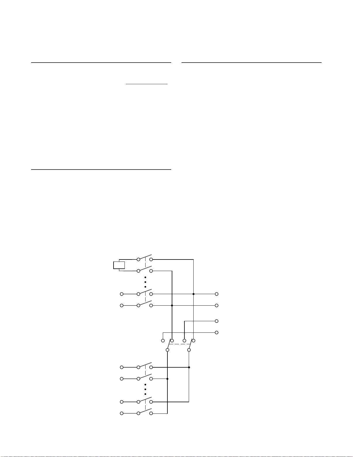
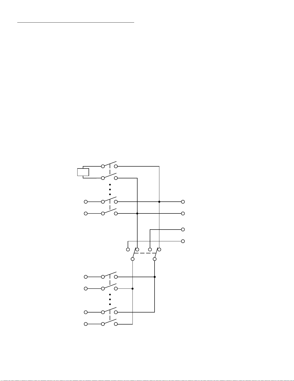
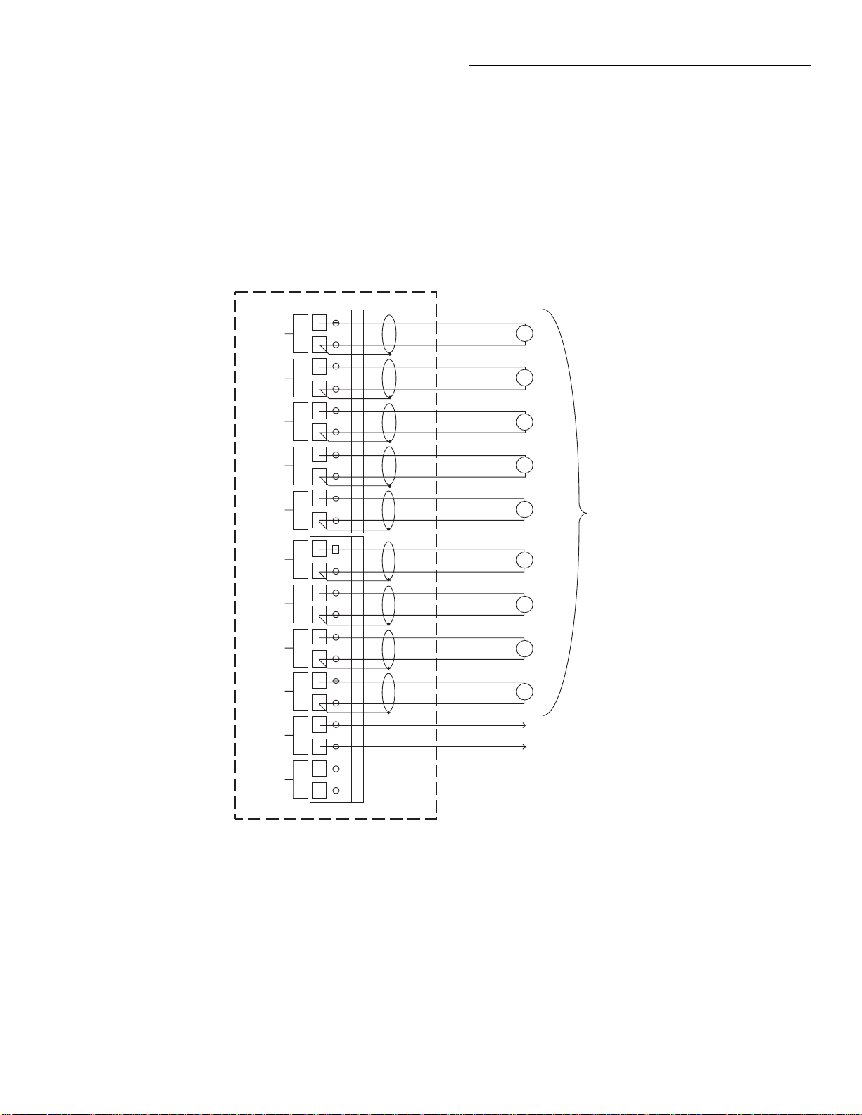
2.3.1 Card configuration
Figure 2-1 shows a simplified schematic diagram of the
Model 2001-TCSCAN. The scanner card has nine input
channels and two outputs. Channel 1 is the reference junction used for thermocouple temperature measurements.
Channel 1
(Reference
Junction)
4-pole paired channels are as follows:
• Channels 2 and 7
• Channels 3 and 8
• Channels 4 and 9
• Channels 5 and 10
CAUTION
Do not attempt to pair channels 1 and 6.
Possible damage to the reference junction may result if a signal is applied to
channel 6 if channels 1 and 6 are used
together in the 4-pole mode.
Channel 2-4
Channel 5
Channel 6
Channel 7-9
Channel 10
HI
LO
HI
LO
HI
LO
HI
OUT A (To DMM
input jacks)
LO
HI
OUT B (To DMM
sense jacks)
LO
2-Pole4-Pole
Figure 2-1
Model 2001-TCSCAN simplified schematic
2-2
Page 19
Card Connections and Installation
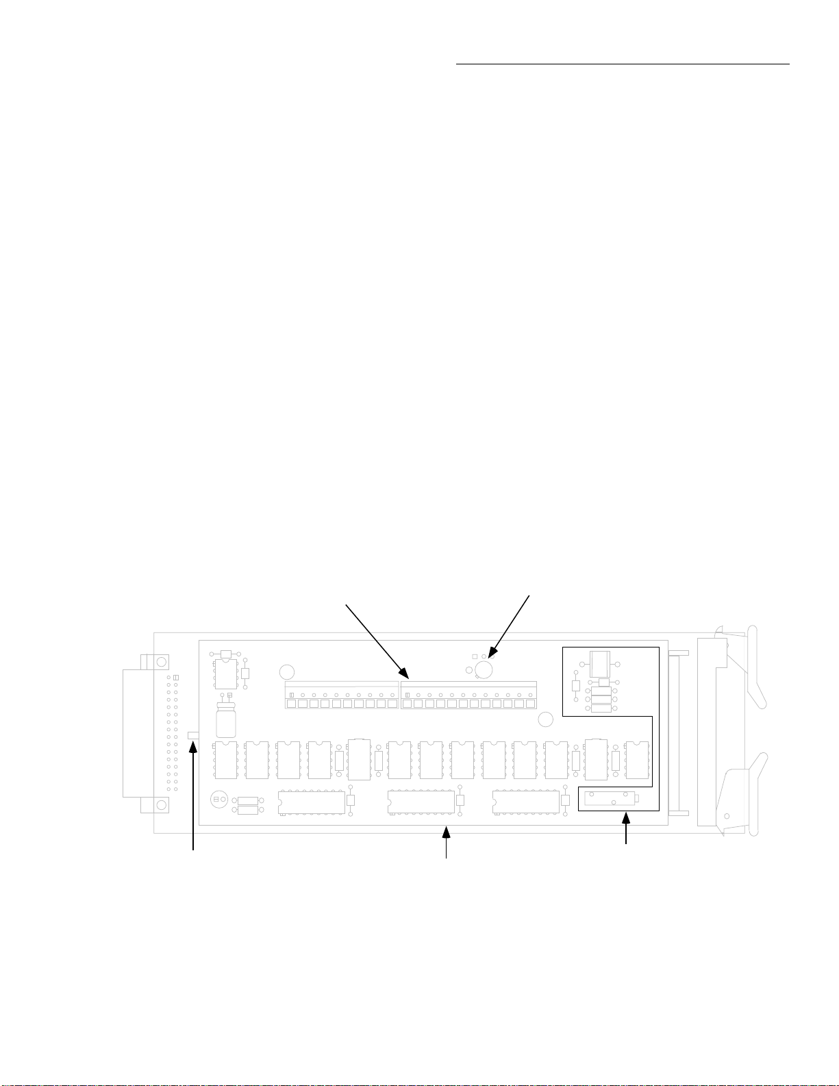
2.3.2 Card connectors
Figure 2-2 shows the input/output connectors for the card.
Card connections include:
• CH 2-10 (channels 2-10): HI and LO input terminals
are provided for each of the nine channels on the card.
NOTE
Channels 5 and 10 have current-limiting
resistors installed. Path resistance for
these two channels is approximately
240 Ω .
• OUT A: HI and LO output connections for all nine
channels in the 2-pole mode or channels 2-5 in the 4pole mode.
• OUT B: HI and LO output connections for channels 710 in the 4-pole mode.
In order to gain access to the connections, first open the plastic shield by pressing in on the locking tab. Swing the shield
away from the circuit board.
2.3.3 Wiring procedure
Perform the following procedure to wire circuitry to the
screw terminals on the scanner card.
WARNING
Make sure all power is off and any
stored energy in external circuitry is
discharged before connecting or disconnecting wires.
CAUTION
Mechanical shock may open or close
latching relays on the scanner card. Before enabling any external sour ces, open
all relays by inserting the Model 2001TCSCAN into the DMM and turning on
the power.
Locking Tab
Figure 2-2
Card connectors
Input/Output Connectors
HI LO
HI LO
HI LO
CH 4
HI LO
CH 5
CH 3
CH 2 OUT A OUT B
HI LO
CH 6
HI LO
HI LO
CH 8
HI LO
CH 9
CH 7
Plastic Shield
Reference Junction Sensor
HI LO
HI LO HI LO
CH 10
Reference Junction Circuitry
2-3
Page 20

Card Connections and Installation
1. Open the plastic shield to gain access to the connectors.
2. Strip approximately
each wire.
Standard thermocouple wire or #22 AWG
stranded wire is recommended for scanner
card connections.
3. Turn the scre w terminal se veral turns counter -clockwise
until the access hole is open. Insert the wire in the access
hole.
4. While holding the wire in place, tighten the connector
screw securely.
Be sure not to over tighten screw terminals, or the connectors may be damaged.
5. Repeat steps 2 through 4 for each wire to be connected.
¼
” of insulation from the end of
NOTE
CAUTION
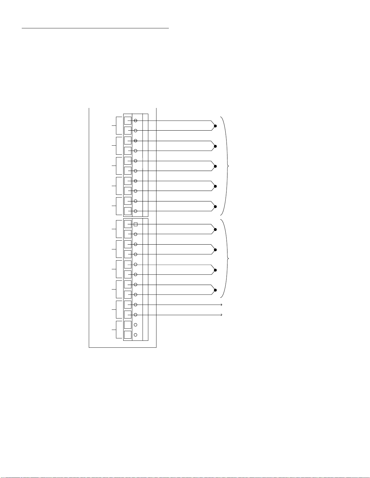
2.3.4 Output connections
Use the supplied test leads for scanner output connections.
Connect red leads to the output (OUT A and OUT B) HI ter minals, and connect black leads to the output LO terminals.
See Figure 2-3 for details. Dress output test leads through the
cable clamp, as described in paragraph 2.3.5. After all wires
are connected and secure, close the plastic shield, and secure
it with the locking tab.
NOTE
If you intend to use the scanner card only
in the 2-pole mode, it is not necessary to
connect output leads to both OUT A and
OUT B. Use only OUT A for the 2-pole
mode.
After the scanner card is installed, the output leads must be
connected to the multimeter rear panel input jacks. See paragraph 2.5.2 for details.
6. Dress input wires through the cable clamp, as discussed
in paragraph 2.3.5.
WARNING
If thermocouples are going to be floated
above 30V RMS, 42.4V peak, 60VDC,
make sure thermocouple wires ha ve adequate insulation.
2.3.5 Dressing leads
After wires are connected to the terminal blocks, they should
be dressed through the cable clamp as shown in Figure 2-4.
T o do so, unlatch the clip that holds the cable clamp together ,
then route all wires flat against the lower half of the clamp.
Clamp the wires down, then secure the clamp with the metal
clip unlatched earlier.
2-4
Page 21

Card Connections and Installation
Figure 2-3
Output connections
HI
To DMM
Input Jacks
LO
Red
Black
Red
HI LO
HI LO
HI LO
HI LO
HI LO
HI LO
HI LO
HI LO
HI LO
CH 2 OUT A OUT B
CH 3
CH 4
CH 5
CH 6
CH 7
CH 8
CH 9
CH 10
HI LO HI LO
Note: OUT B connections not required
for 2-pole operation.
HI
To DMM
Sense Jacks
LO
Black
HI LO
CH 2 OUT A OUT B
Figure 2-4
Routing wires through cable clamp
HI LO
CH 3
HI LO
CH 4
HI LO
CH 5
HI LO
CH 6
HI LO
CH 7
HI LO
CH 8
HI LO
CH 9
HI LO
CH 10
Metal Clip
HI LO HI LO
Cable Clamp
2-5
Page 22
Card Connections and Installation
2.4 T ypical connecting schemes
The following paragraphs discuss typical connections for the
scanner card.
HI HI LO HI LO HI LO HI LO HI LO HI LO HI LO HI LO HI LO HI LO
CH 2
CH 3
CH 4
CH 5
CH 6
CH 7
CH 8
CH 9
CH 10
OUT A
LO
2.4.1 Thermocouple connections
Figure 2-5 shows typical thermocouple connections. Note
that thermocouples are connected to channels 2-10, and output connections are taken from the OUT A terminals.
+
-
+
-
+
Thermocouples
-
+
-
+
-
+
-
+
-
+
-
+
-
HI
LO
Thermocouples
To DMM Input Jacks
OUT B
2001-TCSCAN Card
Figure 2-5
Typical connections for thermocouple scanning
2-6
Page 23
Card Connections and Installation
2.4.2 Voltage connections
Figure 2-6 shows typical connections for voltage measurements. Note that up to nine voltage sources can be switched
with this configuration. This basic configuration can be used
for the following types of measurements:
HI
CH 2
LO
HI
CH 3
CH 4
CH 5
CH 6
CH 7
CH 8
CH 9
CH 10
OUT A
LO
HI
LO
HI
LO
HI
LO
HI
LO
HI LO
HI
LO HI LO HI LO
• DCV
•ACV
• Frequency
Channels (2-10) can be used with this configuration.
HI
V
LO
HI
V
LO
HI
V
LO
HI
V
LO
HI
V
LO
HI
V
LO
HI
V
LO
HI
V
LO
HI
V
LO
HI
To DMM Input Jacks
LO
Voltages
Under Test
OUT B
2001-TCSCAN Card
Figure 2-6
Connections for voltage scanning
HI LO
2-7
Page 24

Card Connections and Installation
■
■
2.4.3 Resistance connections
2-Pole connections
Figure 2-7 shows typical 2-pole resistor test connections.
The 2-pole resistance configuration can be used to test up to
seven DUTs.
NOTE
Channels 5 and 10 should not be used to
switch 2-wire resistance measurements
because of the relatively high path resistance ( ≅ 240 Ω ) of these two channels due
HI HI LO HI LO HI LO HI LO HI LO HI LO HI LO HI LO HI LO HI LO
CH 2
CH 3
CH 4
LO
to the factory-installed current-limiting resistors. (Unless the card is modified; see
paragraph 4.8.)
4-Pole connections
T ypical 4-pole resistance connections are sho wn in Figure 2-
8. This general configuration can be used with channel pairs
2-5 and 7-10 to scan:
• 4-wire resistance measurements.
• 4-wire RTD temperature measurements.
CH 5
CH 6
CH 7
CH 8
CH 9
CH 10
OUT A
OUT B
2001-TCSCAN Card
Figure 2-7
Typical connections for 2-wire resistance scanning
Resistors
Under Test
HI
To DMM Input Jacks
LO
NOTE: Do not use channels 5 and 10
for 2-wire resistance measurements
2-8
Page 25

CH 2
CH 3
CH 4
CH 5
CH 6
CH 7
CH 8
Card Connections and Installation
HI
LO
HI
LO
HI
LO
HI
LO
HI
LO
HI
LO
HI LO
Resistors
Under Test
HI
CH 9
LO HI LO HI LO
CH 10
OUT A
HI LO
OUT B
2001-TCSCAN Card
Figure 2-8
Typical connections for 4-wire resistance scanning
HI
To DMM Input Jacks
LO
HI
To DMM Sense Jacks
LO
2-9
Page 26

Card Connections and Installation
2.5 Card installation and removal
This paragraph explains how to install and remov e the Model
2001-TCSCAN card assembly from the DMM.
WARNING
Installation or removal of the Model
2001-TCSCAN should be performed
only by qualified service personnel.
Failure to recognize and observe standard safety precautions could result in
personal injury or death.
CAUTION
To prevent contamination to the scanner card that could degrade performance, handle the card assembly only
by the card edges and covers.
NOTE
Wiring connections must made before installing the scanner card. See paragraph
2.4 for wiring details.
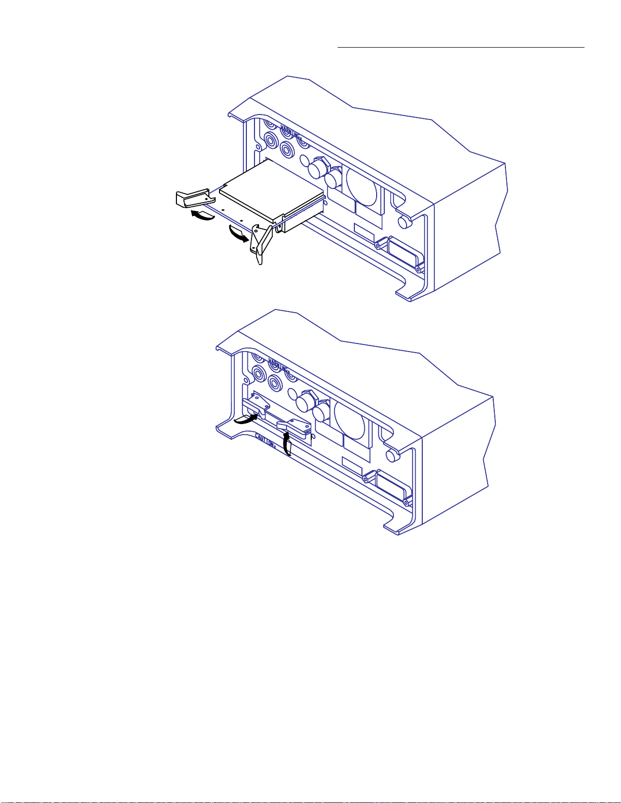
2.5.1 Scanner card installation
Perform the following steps and refer to Figure 2-9 to install
the card assembly in the DMM:
WARNING
Turn off power to all instrumentation
(including the DMM), and disconnect
all line cords. Make sure all power is removed and any stored energy in external circuitry is discharged.
1. Remove the cover plate from the OPTION SLOT on the
rear panel of the DMM. T o do so, pry out the two f asteners, then remove the cover plate.
2. Slide the card edges into the guide rails inside the multimeter (solder side up).
3. With the ejector arms in the unlocked position, carefully
push the card all the way forward until the arms engage
the ejector clips. Push both arms inward to lock the card
into the multimeter.
4. After installation, connect the output leads to the multimeter as discussed below.
2-10
Page 27
Unlock card
Ejector Arms (2)
Card Connections and Installation
Figure 2-9
Card installation
Lock card
WARNING: Installation or removal
should be performed only
by qualified service personel.
2-11
Page 28

Card Connections and Installation
2.5.2 Output connections to multimeter
After installation, connect the scanner card output leads to
the DMM rear panel jacks as follows:
• For 2-pole operation, connect OUT A HI (red) to INPUT HI, and connect OUT A LO (black) to INPUT LO.
See Figure 2-10.
• For 4-pole operation, connect OUT A HI (red) to INPUT HI, and connect OUT A LO (black) to INPUT LO.
Also connect OUT B HI (red) to SENSE HI, and connect OUT B LO (black) to SENSE LO. See Figure 2-11.
NOTE
Be sure to select the rear inputs with the
DMM front panel INPUTS switch when
using the scanner.
2.5.3 Scanner card removal
Follow the steps below to remove the scanner card from the
multimeter:
WARNING
Turn off power to all instrumentation
(including the DMM) and disconnect all
line cords. Make sure all power is removed and any stored energy in external circuitry is discharged.
1. Unlock the card by pulling the latches outward.
2. Carefully slide the card out of the multimeter.
3. If the multimeter is to be operated without a scanner
card installed, install the cover plate over the OPTION
SLOT.
2-12
Page 29

Card Connections and Installation
2-13
Page 30

Card Connections and Installation
Out A
HI (Red)
Use this configuration
for : DCV
ACV
2-wire Ω
2-wire RTD
Frequency
Thermocouple
Input HI
Input LO
Out A
LO (Black)
A. Models 2001 and 2002
Input LO
Use this configuration
for : DCV
ACV
2-wire Ω
2-wire RTD (Model 2010)
Thermocouple
LO (Black)
Input HI
Out A
Out A
HI (Red)
B. Models 2000 and 2010
Figure 2-10
2-pole output connections
2-14
Page 31

Card Connections and Installation
2-15
Page 32

Card Connections and Installation
Sense HI
Out A
HI (Red)
Out B
HI (Red)
Use this configuration
for : 4-wire ohms
4-wire RTD
Input HI
Sense LO
Out A
LO (Black)
Input LO
Out B
LO (Black)
A. Models 2001 and 2002
Sense HI
Sense LO
Out B
HI (Red)
Out B
LO (Black)
Use this configuration
for : 4-wire ohms
4-wire RTD (Model 2010)
Input LO
Out A
LO (Black)
Input HI
Out A
HI (Red)
B. Models 2000 and 2010
Figure 2-11
4-pole output connections
2-16
Page 33

3
Operation
3.1 Introduction
This section contains detailed information on front panel and
IEEE-488 bus operation of the Model 2001-TCSCAN. The
information in this section is organized as follows:
3.2 Signal limitations: Summarizes the maximum signals
that can be applied to the Model 2001-TCSCAN.
3.3 Scanner card detection: Discusses how the scanner
card is detected and how to determine whether or not
the card is installed with a bus command.
Models 2001 and 2002 operation:
3.4 Front panel scanner controls: Gives an overview of
the Models 2001 and 2002 Multimeter front panel
controls used to control the scanner card.
3.5 IEEE-488 bus scanner commands: Summarizes bus
commands necessary to control the scanner card.
3.6 Opening and closing channels: Covers the basic
methods for closing and opening channels.
3.7 Scanning channels: Details how to configure scan
parameters and how to perform scanning.
3.8 Temperature measurements: Describes using the
scanner card to make temperature measurements using
themocouples and RTD probes.
Models 2000 and 2010 operation :
3.9 Basic front panel operation: Explains how to use the
Models 2000 and 2010 to perform basic scanner card
operations using the Model 2001-TCSCAN card.
3.10 Temperature measurements: Explains how to use
the scanner card with the Models 2000 and 2010 to
make temperature measurements.
3.11 Remote operation: Summarizes the SCPI commands
necessary to control the scanner card and make
temperature measurements.
Models 2000, 2001, 2002, and 2010 :
3.12 Typical applications: Discusses typical applications
for the Model 2001-TCSCAN.
3.13 Measurement considerations: Discusses a number
of measurement considerations that should be taken
into account when using the scanner.
NOTE
Before using the Model 2001-TCSCAN
scanner card, you should be thoroughly familiar with the operation of the Model
2001 Multimeter. See the Model 2001 Operator’s Manual for details.
3-1
Page 34

Operation
3.2 Signal limitations
CAUTION
To prevent damage to the Model 2001TCSCAN, do not exceed the maximum
signal level specifications of the card.
To prevent over-heating or damage to the relays, never
exceed the following maximum input signal levels:
DC signals: 110V DC, 1A switched, 30VA (resistive load).
AC signals: 125V rms or 175V AC peak, 1A switched,
62.5VA (resistive load). (Channels 5 and 10 maximum
power = 0.25VA due to factory installed current-limiting
resistors. See paragraph 4.8 for modification.)
3.3 Scanner card detection
3.3.1 Power-up detection
The scanner card is detected only at power-on. If the card is
plugged into the DMM after the power is turned on, the card
will not be recognized as being present by the DMM.
Refer to the individual DMM operator’s manual for more
details on using the *OPT? query.
3.4 Front panel scanner controls
NOTE
Use paragraphs 3.4 through 3.8 for scanner card operation using the Models 2001
and 2002 DMMs. Models 2000 and 2010
1
The following paragraphs give an overview of the various
Model 2001 Multimeter controls used with the scanner.
Figure 3-1 shows the front panel of the Models 2001 and
2002. Controls that affect Model 2001-TCSCAN operation
include:
DMM operation is covered in paragraphs
3.9 through 3.11.
• CHAN: Allo ws you to open and close channels directly .
• CONFIG-CHAN: Defines the measurement functions
for each scanner channel.
• CONFIG-SCAN: Selects internal/external scan list.
• SCAN: Enters scan configuration menu.
CAUTION
Plugging in the scanner card with power turned on may result in damage to
both the Model 2001-TCSCAN and the
DMM.
If the card is not present at power-on, scanner bus commands
or queries will generate a “Missing hardware error”, and
front panel operations pertaining to the scanner will inform
you that no scanner is present.
3.3.2 Scanner option bus query
*OPT? is an IEEE 488.2 common query which will allow
you determine whether or not the Model 2001-TCSCAN
card is installed. The response to this query has two fields.
The first field identifies the presence or absence of expansion
memory, and the second field indicates whether or not the
scanner is present as follows:
• 0: Scanner not installed.
• and : Manually scans through channels.
• TEMP: Enables temperature measurements.
• CONFIG-TEMP: Selects sensor type, thermocouple
type, and reference junctions.
3.4.1 Open and close channels (CHAN)
The CHAN key allows you directly:
• Open any closed channel(s) immediately.
• Close a specific channel (or channel pair for 4-wire
functions).
Pressing CHAN will display the following menu choices:
CHANNEL SELECTION
CLOSE-CHANNEL OPEN-ALL-CHANNELS
• 2001-SCAN: Model 2001-TCSCAN scanner card installed.
3-2
Page 35

■
■
Operation
ERR REM TALK LSTN SRQ REAR REL FILT MATH 4W AUTO ARM TRIG SMPL
PREV
DISPLAY
NEXT
POWER
DCV ACV DCI ACI Ω2 Ω4
REL TRIG
INFO LOCAL EXIT ENTER
CHAN
• Close channel
• Open channel
CONFIG-CHAN
• Define internal channel functions
• Define external channel functions
• Define alternate function
STORE RECALL
CHAN SCAN
FILTER MATH
CONFIG MENU
SCAN
• Scan configuration
CONFIG-SCAN
• Select internal scan list
• Select external scan list
FREQ TEMP
RANGE
AUTO
RANGE
SENSE
Ω 4 WIRE
350V
PEAK
INPUTS
FR
FRONT/REAR
CAL
INPUT
HI
1100V
!
PEAK
LO
2A 250V
AMPS
500V
PEAK
TEMP
• Enable temperature measurements
CONFIG-TEMP
• Select sensor type
• Choose thermocouple type
• Define reference junction
Figure 3-1
Models 2001 and 2002 front panel scanner controls
OPEN-ALL-CHANNELS
Selecting OPEN-ALL-CHANNELS will immediately open
any closed scanner card channel(s).
CLOSE-CHANNELS
Selecting CLOSE-CHANNEL will display the following
message prompting you to select the channel to close:
ENTER CHAN#01 (1-10)
The field entry after “ENTER CHAN#” indicates the channel to close. To close a channel, simply use the cursor and
range keys to select the number of the channel to close, then
press ENTER. The number of the closed channel will be displayed on the front panel along with normal readings. Keep
in mind that channel 1 is the reference junction.
• Manually scan channels
EXIT
• Disable scanning
Selecting a different channel from the one that is presently
closed will cause the closed channel to open and allow a settling time before closing the selected channel.
Channel relays will be closed according to the presently
selected function. If a 2-wire function is used, only the relay
for that one channel will be closed. If a 4-wire function is
selected, both the selected channel relay and the matching
relay pair will close. For example, closing channel 2 will also
close the channel 7 relay. Fixed 4-pole relay pairs are:
• 2 and 7
• 3 and 8
• 4 and 8
• 5 and 10.
3-3
Page 36

Operation
■
Ω
Ω
Ω
■
■
3.4.2 Configure channels (CONFIG-CHAN)
CONFIG-CHAN allows you to:
• Select measurement functions for internal (Model
2001-TCSCAN) channels.
• Select measurement functions for channels in an external scanner used with the Model 2001/2002.
• Define an alternate measurement function which can
then be assigned to specific channels.
Pressing CONFIG then CHAN will display the following
menu:
CONFIGURE CHANNELS
INTERNAL-CHANS EXTERNAL-INPUTS
SAVE-ALT-FCN RESTORE-ALT-FCN
INTERNAL-CHANS
The INTERNAL-CHANS selection allows you to set the
measuring function for each of the Model 2001-SCAN
channels while scanning. When this selection is made, the
following submenu will be displayed:
SET INTERNAL CHANS
1=DCV 2=DCV 3=DCV 4=DCV 5=DCV
6=DCV 7=DCV 8=DCV 9=DCV 10=DCV
corresponding paired channel 7-10. Once Ω 4W is selected
on channels 2 to 5, changing the assignment to a different
function will de-assign the paired channel and change the
function to “---” (none).
CAUTION
Four-wire functions should not be used
with channels 1 and 6.
TMP function: Similarly, the TMP selection is valid only
for channels 2-5 if the RTD temperature sensor is a 4-wire
type. If a 2-wire RTD type is used, channels 6-10 could be
assigned to the TMP function, but if the sensor type is later
change to 4-wire RTD, any channel from 6-10 will then be
set to “---” (none). Thermocouple TMP measurements can
be assigned to channels 2-10.
No function (---): Selecting none (---) effectively removes
that channel from the scan list. When scanning, the instrument will skip any channels that have no function defined.
JN functions: JN1 through JN5 are used to assign a refer-
ence junction to a channel. With the Model 2001-TCSCAN,
the reference junction must be assigned to channel 1.
With this menu displayed, use the cursor keys to select the
channel, and use the up arrow and down arrow (range) keys
to select the desired measuring function for each channel:
DCV: DC volts
ACV : A C volts
2W: 2-wire ohms
4W: 4-wire ohms
FRQ: frequency
TMP: temperature
ALT: alternate function (see below)
JN1 – JN5: Reference junctions
--- : None
4W function: The Ω 4W function is valid only for chan-
nels 2-5. If selected, “PRD” (paired) will be shown on the
EXTERNAL-INPUTS
This menu item allows you to select measurement functions
for an external scanner used with the Model 2001/2002 Multimeter. See the Model 2001/2002 Operator’s Manual for details.
SAVE-ALT-FCN/RESTORE-ALT-FCN
An ALT (alternate) function is one that cannot be directly accessed with one of the eight function keys. For example, assume that you select the A CV peak function using CONFIGACV. You can then use SAVE-ALT to assign peak ACV to
the ALT function. Whenever the ALT function is encountered in the scan list, the instrument will switch to the ACV
peak function for that channel even if the instrument is measuring a different type of ACV (RMS for example).
You can also use the ALT function to store an existing main
function but with a different set of operating parameters. For
3-4
Page 37

■
■
■
Operation
example, you could set up thermocouple operating parameters for the TMP function and RTD setup parameters as the
ALT function. This arrangement allows you to specify
changes in virtually any measurement parameter from channel to channel even if the measurement functions are the
same.
SAVE-ALT-FCN: Stores the presently selected function
and all its configured settings as the ALT function.
RESTORE-ALT-FCN: Restores the function that was
saved as the ALT function and all associated settings as if a
normal function change were taking place.
3.4.3 Scan configuration (CONFIG-SCAN)
CONFIG-SCAN allows you to select the internal or external
channel list for scanning.
Pressing CONFIG-SCAN will display the following menu:
SCAN OPERATION
INTERNAL EXTERNAL RATIO DELTA
These choices select the action the instrument will take when
it is triggered.
INTERNAL
This selection enables scanning with the internal Model
2001- TCSCAN scanner card.
3.4.4 Using SCAN to configure scan parameters
and start scanning
Once the internal or external scan list is enabled, use the
SCAN key to configure scan count, scan interval, and enable
buffer storage. The steps below outline the basic procedure
for using the SCAN key to configure internal scanner operation.
1. From normal display, press CONFIG-SCAN. The instrument will display the following:
SCAN OPERATION
INTERNAL EXTERNAL RATIO DELTA
2. Select INTERNAL, then press ENTER.
3. Press SCAN. The unit will display the following message:
SCAN COUNT = 00010
4. Using the range and cursor keys, select the number of
scan sequences, then press ENTER. The instrument will
display the following:
USE SCAN TIMER?
YES NO
5. If you do not wish to use the scan timer (interval between scans), select NO, then press ENTER, and go on
to step 7. If you wish to use and program the interval between scans, select YES, then press ENTER. The instrument will display the following:
EXTERNAL
This menu selection enables scanning with an external scanner card located in a switching mainframe. This selection operates in a manner similar to INTERNAL except that the
internal scanner card is not used.
RATIO/DELTA
RATIO and DELTA should not be used with the Model
2001-TCSCAN. These selections are intended for use with a
different scanner card.
INTRVL = 000002.500
6. Using the range and cursor keys, select the desired interval (in seconds) between scan sequences, then press ENTER.
7. The instrument will then prompt you as to whether or
not you wish to store data in the buffer as follows:
DATA TO MEMORY?
YES NO
8. To store scanned data in the buffer, select YES; otherwise choose NO, then press ENTER.
3-5
Page 38

Operation
9. If you elected to store data in memory, the instrument
will prompt you as follows:
00100 RDGS TO BUFFER
Press ENTER to continue.
NOTE
Use CONFIG-STORE to program the
number of readings to store.
10. Press ENTER to begin scanning at the following
prompt:
Press ENTER to begin
0010 scans of 10 channels
11. The instrument will then scan using selected scanning
parameters. If you elected to store data in memory, the
instrument will display the reading number on the bottom line of the display as readings are stored.
12. After readings are stored, the following will be displayed:
SCAN COMPLETE
RECALL-DATA SCAN-AGAIN EXIT
13. Select the desired operation, then press ENTER.
3.4.5 Using EXIT to stop scanning
To disable scanning while in progress, press the EXIT key.
3.4.6 Manual scanning
The and keys can be used to manually scan through
channels. In order to use this feature, first close a channel using the CHAN key . Use to increment channels, or use
to decrement channels. To view adjacent channels simultaneously, turn on the multiple displays with the NEXT key.
3.5 IEEE-488 bus scanner commands
Table 3-1 summarizes commands that are typically used for
scanning and temperature measurements over the IEEE-488
bus. Note that the query form for most of the listed commands is not included. For more information on these and
other bus commands, refer to the Model 2001 or 2002 User’ s
Manual.
Programming examples in paragraphs 3.6, 3.7, and 3.8.4 are
provided using both HP BASIC and QuickBASIC 4.5 languages. The QuickBASIC examples use the HP-style Universal Language Driver (CECHP).
3-6
Page 39

Table 3-1
Summary of SCPI commands (Models 2001 and 2002 )
Command Description
FORMat command summary
Operation
:FORMat
:ELEMents <item list>
ROUTe command summary
:ROUTe
:CLOSe <list>
:STATe?
:CLOSe? <list>
:OPEN <list>|ALL
:ALL
:OPEN? <list>
:SCAN
[:INTernal] <list>
:FUNCtion <list>, <function>
:LSELect <name>
SENSe command summary
[:SENSe[1]]
:FUNCtion <name>
:ALTernate [1]
:SAVe
:RECall
Command to specify data elements to send over the bus:
Specify data elements (READing, CHANnel, RNUMber, UNITs,
TIMEstamp, STATus).
Commands to control 2001-TCSCAN:
Close specified channels.
Query closed channels.
Query specified channels (1=closed, 0=open).
Open specified channels or all channels.
Open all channels.
Query specified channels (1=open, 0=closed).
Path to scan channels.
Configure internal scan list.
Assign function to specified channels (see NOTE at end of table).
Select scan list (INTernal, NONE).
Commands to configure measurements:
Select function (‘TEMPerature’, ‘VOLTage:AC’, ‘VOLTage:DC’,
‘RESistance’, ‘FRESistance’, ‘FREQuency’).
Program alternate function.
Save alternate function.
Recall alternate function.
:TEMPerature
:TRANsducer <name>
:RTD
:TYPE <name>
:RZERo <NRf>
:ALPHa <NRf>
:BETA <NRf>
:DELTa <NRf>
:TCouple
:TYPE <name>
:RJUNctionX
:RSELect <name>
:SIMulated <n>
:REAL
:TCOefficient <n>
:OFFSet <n>
:ACQuire
Path to configure temperature measurements:
Select transducer (RTD, FRTD, or TCouple).
Configure RTD temperature measurements:
Select RTD sensor type (PT100, D100, F100, PT3916, PT385
or USER).
Specify constant for USER type (0 to 1000).
Specify constant for USER type (0 to 0.01).
Specify constant for USER type (0 to 1.00).
Specify constant for USER type (0 to 5.00).
Configure thermocouple sensor.
Select thermocouple type (J,K,T,E,R,S, or B).
Configure reference junction; where X=1 for Model
2001-TCSCAN.
Select reference type (SIMulated or REAL).
Specify simulated temperature in˚C (0 to 50).
Configure real reference junction:
Specify temp coefficient (-0.09999 to 0.09999).
Specify voltage coefficient at 0˚C (-0.09999 to 0.09999).
Update reference temperature.
3-7
Page 40

Operation
Table 3-1 cont.
Summary of SCPI commands (Models 2001 and 2002)
Command Description
TRACe command summary
:TRACe
:POINts <n>
:AUTO <b>
:FEED <name>
:CONTrol <name>
:DATA?
Commands to configure buffer:
Specify buffer size.
Enable or disable auto buffer sizing (uses :trigger:count).
Select source of readings (SENSe[1], CALCulate [1], NONE).
Select buffer control mode (NEVer, NEXT, ALWays).
Read all readings in the buffer.
Trigger command summary
:INITiate
[:IMMediate]
:CONTinuous <b>
:TRIGger
:COUNt <n>
:SOURce <name>
:TIMer <n>
Initiation commands:
Initiate one trigger cycle.
Enable or disable continuous initiation.
Trigger layer commands:
Specify total number of channels to scan (1 to 99999).
Select control source (IMMediate, TIMer, MANual).
Set timer interval (0 to 999999.999 seconds).
UNITs command summary
:UNIT
:TEMPerature <name>
NOTE: The SCAN:INTernal <function> parameter (ROUTe command summary) is one of the following:
VOLTage:DC DC volts
VOLTage:AC AC volts
TEMPerature Temperature
FREQuency Frequency
RESistance 2-wire ohms
FRESistance 4-wire ohms
RJUNctionX Reference junction (X = 1 to 5)
NONE No function (skips listed channel during scan).
ALTernate[1] Alternate function.
Command to select temperature units:
Select temperature measurement units (C, CEL, F, FAR, K).
3-8
Page 41

■
■
Operation
■
■
3.6 Closing and opening channels
Individual scanner card channels are closed and opened using the CHAN key . The follo wing paragraphs discuss closing
and opening channels from the front panel as well as with
bus commands.
3.6.1 Closing channels
Front panel
Use the front panel CHAN key to close specific channels as
follows:
1. From normal display, press the CHAN key. The instrument will display the following menu:
CHANNEL SELECTION
CLOSE-CHANNEL OPEN-ALL-CHANNELS
2. Select CLOSE-CHANNEL, then press ENTER. The
Model 2001 will display the following prompt:
ENTER CHANNEL# 01 (1-10)
3. Use the cursor and range keys to select the channel you
wish to close (1-10), then press ENTER. An y previously
closed channel will open, and the selected channel will
close.
NOTE
Once a channel is closed, use the or
key to manually scan through channels. Also, you can use the NEXT display to view
three successive channels simultaneously.
3.6.2 Opening channels
Front panel
Use the front panel CHAN key to open any closed channels
as follows:
1. Press the CHAN key. The instrument will display the
following menu:
CHANNEL SELECTION
CLOSE-CHANNEL OPEN-ALL-CHANNELS
2. Select OPEN-ALL-CHANNELS, then press ENTER.
The closed channel will open immediately.
IEEE-488 bus
Use the :ROUT :OPEN command to open the closed channel.
For example, either of the following program statements
could be used to open channel 3:
HP BASIC
OUTPUT 716; “:rout:open (@3)”
QuickBASIC 4.5
PRINT #1, “output 16; :rout:open (@3)”
(You can also use :ROUT:OPEN:ALL or :ROUT:OPEN ALL
to open channels.)
3.7 Scanning channels
Channels are scanned by configuring channels and programming the Model 2001/2002 to perform a scan. The following
paragraphs outline step-by-step procedures for performing basic scanning from the front panel and over the IEEE-488 bus.
IEEE-488 bus
Use the :ROUT:CLOSE command to close the desired
channel. For example, either of the following program
statements could be used to close channel 3.
HP BASIC
OUTPUT 716; “:rout:close (@3)”
QuickBASIC 4.5
PRINT #1, “output 16; :rout:close (@3)”
3.7.1 Front panel scanning
Step 1: Configure channels
Use CONFIG-CHAN to select the measurement functions
for each of the scanner channels as follows:
1. Press CONFIG-CHAN. The instrument will display the
following menu:
CONFIGURE CHANNELS
INTERNAL-CHANS EXTERNAL-INPUTS
3-9
Page 42

Operation
2. Select INTERNAL-CHANS, then press ENTER. The
multimeter will display the following menu:
SET INTERNAL CHANS
1=DCV 2=DCV 3=DCV 4=DCV 5=DCV
3. Using the cursor keys, select the desired channel (press
the right cursor key to display channels 6 through 10).
4. Using the range keys, select the desired measurement
function: DCV, ACV, Ω2W, Ω4W, FRQ, TMP, JN1-
JN5, ALT, --- (None).
5. Repeat steps 3 and 4 for each of the channels you wish
to scan. NOTE: Select --- (none) to omit a channel from
the scan list.
6. After selecting all measurement functions, press ENTER.
7. Press EXIT to return to normal display.
Step 2: Configure and start scan
Configure the scan as follows:
1. Press CONFIG-SCAN. The Model 2001/2002 will display the following:
HP BASIC
OUTPUT 716; “:rout:scan:int:func (@2), ‘volt:dc’”
OUTPUT 716; “:rout:scan:int:func (@3), ‘volt:ac’”
OUTPUT 716; “:rout:scan:int:func (@6), ‘res’”
QuickBASIC 4.5
PRINT #1, “output 16; :rout:scan:int:func (@2), ‘volt:dc’”
PRINT #1, “output 16; :rout:scan:int:func (@3), ‘volt:ac’”
PRINT #1, “output 16; :rout:scan:int:func (@6), ‘res’”
If you wish to use the same function (for example DCV) on all
three channels, either of the following commands can be used:
HP BASIC
OUTPUT 716; “:rout:scan:int:func (@2,3,6), ‘volt:dc’”
QuickBASIC 4.5
PRINT #1, “output 16; :rout:scan: int:func (@2,3,6),volt:dc’”
Step 2: Program internal scan list and start scan
SCAN OPERATION
INTERNAL EXTERNAL RATIO DELTA
2. Select INTERNAL, then press ENTER.
3. Press SCAN, and follow the prompts to configure scanning. See paragraph 3.4.4 for details.
3.7.2 IEEE-488 bus scanning
Step 1: Program channel functions
Use :ROUT:SCAN:INT:FUNC to program functions for the
selected channels. For example, assume that you want to
measure DC volts on channel 2, AC volts on channel 3, and
2-wire resistance on channel 6. The commands are as follows:
Use the :ROUT:SCAN:INT command to program a scan list
(channels you wish to scan). For example, assume that you
wish to scan channels 2, 3, and 6. This scan list can be
programmed using either of the following commands:
HP BASIC
OUTPUT 716; “:rout:scan:int (@ 2,3,6)”
QuickBASIC 4.5
PRINT #1, “output 16; :rout:scan:int (@2,3,6)”
Scanning will begin immediately when this command is sent.
To disable scanning, send the :ROUT:SCAN:LSEL NONE
command:
HP BASIC
OUTPUT 716; “:rout:scan:lsel none”
QuickBASIC 4.5
PRINT #1, “output 16; :rout:scan:lsel none”
3-10
Page 43

Operation
3.8 T emperature measurements
The following paragraphs discuss using the Model 2001TCSCAN for making temperature measurements using
thermocouples and RTD probes.
3.8.1 Thermocouple temperature measurements
The Model 2001-TCSCAN can be used to make temperature
measurements with the following thermocouple types: J, K,
T , E, R, S, B. Measurements can be made either by automatic
scanning, or by manually closing specific channels. The following paragraphs outline the procedures for making thermocouple temperature measurements using both of these
methods. For more detailed information on temperature
measurements in general, refer to the Model 2001/2002 Operator’s manual.
■ Thermocouple scanning
Follow the steps below to automatically scan through thermocouples and make temperature measurements.
4. Choose THERMOCOUPLE-TYPE, then press ENTER.
The list of supported thermocouple types will be displayed:
THERMOCOUPLE TYPE
JKTERSB
5. Select the thermocouple type to match those you are using, then press ENTER. Select REF-JUNCTIONS on
the displayed menu, then press ENTER. The Model
2001 will display the following:
CONFIGURE REFJCNS
JCN1 JCN2 JCN3 JCN4 JCN5
6. Select the desired reference junction (for example,
JCN1), then press ENTER. The instrument will display
the following message:
REFERENCE JUNCTION#1
CONFIGURE ACQUIRE-REF-TEMP
7. Select CONFIGURE, then press ENTER. The following
will be displayed:
Step 1: Connect thermocouples
Connect your thermocouples to the scanner input connectors
using the general scheme shown in Figure 2-5 in Section 2.
Step 2: Select thermocouple type and reference junction
parameters
1. From normal display, press CONFIG-TEMP. The instrument will display the following:
CONFIG TEMPERATURE
SENSOR UNITS SPEED FILTER RESLN
2. Select SENSOR, then press ENTER. The following will
be displayed:
TEMP SENSOR TYPE
4-WIRE-RTD RTD THERMOCOUPLE
3. Select THERMOCOUPLE, then press ENTER. The
Model 2001 will then display the thermocouple setup
menu:
CONFIGURE REFJCN#1
SIMULATED-TEMP REAL-JUNCTION
8. Select REAL-JUNCTION, then press ENTER. The instrument will prompt you to enter the reference junction
coefficient:
REFJCN#1=+00.20mV/¡C
9. If necessary, set the displayed value to +200µV/°C
(+0.20mV/°C), then press ENTER. The unit will then
prompt you for the reference offset:
OFFSET1=+54.63mV@0¡C
10. If necessary, set the offset to +54.63mV @ 0°C, then
press ENTER.
11. Press EXIT as necessary to return to the CONFIG TEMPERATURE menu, then select your UNITS, SPEED,
FILTER, and RESLN, as required.
12. Press EXIT to return to normal display.
THERMOCOUPLE SETUP
THERMOCOUPLE-TYPE REF-JUNCTIONS
3-11
Page 44

Operation
Step 3: Configure channels
1. Press CONFIG-CHAN, select INTERNAL-CHANS,
then press ENTER. The display will appear as follows:
SET INTERNAL CHANS
1=DCV 2=DCV 3= DCV 4=DCV 5=DCV
2. Using the range and cursor keys, set the channel functions as follows:
Channel 1: JN1 (or JN2-JN5 if using those junctions)
Channels 2-10: TMP for thermocouple channels, --- for
unused channels, or other valid function if used.
3. After setting all channel functions, press ENTER to return to normal display.
Step 4: Configure and scan channels
1. From normal display, press CONFIG-SCAN. The instrument will display the following:
SCAN OPERATION
INTERNAL EXTERNAL RATIO DELTA
Step 1: Connect Thermocouples
Connect your thermocouples to the desired channels, as covered in Figure 2-5, Section 2.
Step 2: Acquire reference junction temperature
1. Press the TEMP key to place the instrument in the temperature measurement mode.
2. Press CHAN. The unit will display the following:
CHANNEL SELECTION
CLOSE-CHANNEL OPEN-ALL-CHANNELS
3. Select CLOSE-CHANNEL, then press ENTER. The
display will appear as follows:
ENTER CHAN#01 (1-10)
4. If necessary, use the range and cursor keys to select
channel 1 (reference junction channel), then press ENTER. The unit will return to normal display, and it
should indicate that channel 1 is closed.
5. Press CONFIG-TEMP. The Model 2001/2002 will display the following message:
2. Select INTERNAL, then press ENTER.
3. Press SCAN, then follow the prompts to begin scanning.
See paragraph 3.4.4 for details.
■ Manual temperature measurements
In addition to scanning through channels to make temperature measurements, you can also make such measurements
manually. In order to do so, you must first acquire the reference junction temperature and then manually close or scan
through thermocouple channels. Note that the reference
junction acquisition process should be repeated often, particularly if the ambient temperature changes; otherwise, temperature reading accuracy will be reduced.
NOTE
If you attempt to measure thermocouple
temperature before acquiring the reference
junction, the front panel “ERR” annunciator will indicate that an error has occurred.
CONFIG TEMPERATURE
SENSOR UNITS SPEED FILTER RESOLN
6. Choose SENSOR, then press ENTER. The unit will display the sensor type menu:
TEMP SENSOR TYPE
4-WIRE-RTD RTD THERMOCOUPLE
7. Select THERMOCOUPLE, then press ENTER. The
thermocouple setup menu will be displayed:
THERMOCOUPLE SETUP
THERMOCOUPLE-TYPE REF-JUNCTIONS
8. Select THERMOCOUPLE-TYPE, then press ENTER.
Select your thermocouple type as outlined above. Select
REF-JUNCTIONS, then press ENTER. The following
will be displayed:
CONFIGURE REFJCNS
JCN1 JCN2 JCN3 JCN4 JCN5
3-12
Page 45

Operation
9. Choose JCN1, then press ENTER. The selection menu
below will be displayed:
REFERENCE JUNCTION#1
CONFIGURE ACQUIRE-REF-TEMP
10. Select ACQUIRE-REF-TEMP, then press ENTER. The
reference junction temperature has now been acquired.
11. Press EXIT as necessary to return to the CONFIG TEMPERATURE menu, then select the UNITS, SPEED,
FILTER, and RESLN, as required.
12. Press EXIT to return to normal display after completing
temperature configuration.
Step 3: Close channels and display temperature
Close the desired channel (2-10) to display the temperature
for that channel. Use the CHAN key and CLOSE-CHANNEL menu selection to close a specific channel. Once a
channel is closed, you can manually scan through channels
using the and keys. Keep in mind that the reference
junction temperature should be acquired often to assure measurement accuracy, especially if the ambient temperature
changes. Remember that the TEMP function must be selected, and channel 1 must be closed to acquire the reference
junction temperature.
Do not use channels 5 and 10 for 2-wire probes because of
the higher path resistance of these channels.
Step 2: Select sensor type and units
1. From normal display, press CONFIG-TEMP. The instrument will display the following:
CONFIG TEMPERATURE
SENSOR UNITS SPEED FILTER RESLN
2. Select SENSOR, then press ENTER. The following will
be displayed:
TEMP SENSOR TYPE
RTD 4-WIRE-RTD THERMOCOUPLE
3. Select RTD or 4-WIRE-RTD as appropriate for the sensor type you are using, then press ENTER. The instrument will display the following:
SET RTD TYPE
PT385 PT3916 USER-RTD
4. Select the RTD type from among the displayed types,
then press ENTER.
5. Select UNITS, then press ENTER. The unit will display
the following selections:
3.8.2 RTD temperature measurements
The following paragraphs outline the procedures for making
temperature measurements from the front panel using the
scanner. F or more detailed information on temperature measurements in general, refer to the Model 2001/2002 Operator’s manual.
Step 1: Connect RTD probes
Connect RTD probes to the scanner using the basic
resistance connections outlined in Section 2. For 4-wire
probes, pair the connections as follows:
• Channels 2 and 7: probe #1
• Channels 3 and 8: probe #2
• Channels 4 and 9: probe #3
• Channels 5 and 10: probe #4
SET TEMP UNITS
DEG-C DEG-F K
6. Choose the type of temperature units you desire to use:
°C, °F, or K, then press ENTER.
7. Before exiting the temperature configuration menu, select speed, filter, and resolution operating modes, if desired.
8. Press EXIT to return to normal display.
Step 3: Configure channels
1. Press CONFIG-CHAN. The instrument will display the
following:
CONFIGURE CHANNELS
INTERNAL-CHANS EXTERNAL-INPUTS
3-13
Page 46

Operation
2. Select INTERNAL-CHANS. The Model 2001/2002
will display the following:
SET INTERNAL CHANS
1=DCV 2=DCV 3=DCV 4=DCV 5=DCV
3. Use the cursor and range keys to select channels and
functions. Set the function type to TMP for all channels
connected to RTD probes. Select --- (none) for channels
with no connections.
4. Press ENTER to return to normal display.
Step 4: Configure scan and scan channels
1. From normal display, press CONFIG-SCAN. The instrument will display the following:
SCAN OPERATION
INTERNAL EXTERNAL RATIO DELTA
2. Select INTERNAL, then press ENTER.
3. Press SCAN, then follow the prompts. See paragraph
3.4.4 for details.
2. Select SENSOR, then press ENTER. The unit will display the following:
TEMP SENSOR TYPE
4-WIRE-RTD RTD THERMOCOUPLE
3. Select 4-WIRE-RTD or RTD as appropriate, then press
ENTER. The instrument will then prompt for R TD type:
SET RTD TYPE
PT385 PT3916 USER-RTD
4. Choose the appropriate RTD type, then press ENTER.
5. Choose the desired UNITS, SPEED, FILTER, and
RESLN for the RTD measurements.
6. Press EXIT to return to normal display.
7. Press TEMP to select the temperature function.
8. Press CONFIG-CHAN. The Model 2001/2002 will display the following:
CONFIGURE CHANNELS
INTERNAL-CHANS EXTERNAL-INPUTS
SAVE-ALT-FCN RESTORE-ALT-FCN
3.8.3 Using RTD and thermocouple sensors
together
RTD and thermocouple sensors can be used together with the
scanner. T o do so, setup the TMP function for one type of temperature sensor, and configure the ALT function for the other
type of temperature sensor. In the e xample belo w, the thermocouple sensor type is assigned to the TMP function, and the
RTD temperature sensor is assigned to the ALT function.
Step 1: Connect temperature sensors
Connect your RTD probes and thermocouples to the scanner
input connectors using the general scheme shown in Section
2. Be sure to use the appropriate 2-wire or 4-wire connec-
tions for the RTD probes. (Do not use channels 5 and 10 for
2-wire probes because of the higher path resistance of these
two channels.)
Step 2: Assign RTD sensor type to the ALT function
1. From normal display, press CONFIG-TEMP. The model
will display the following:
9. Select SAVE-ALT-FCN, then press ENTER. The unit
will inform you that the temperature function has been
saved as the alternate function:
TMP settings saved
as the ALT function
10. Press EXIT to return to normal display.
Step 3: Select thermocouple type and reference junction
parameters
1. From normal display, press CONFIG-TEMP. The instrument will display the following:
CONFIG TEMPERATURE
SENSOR UNITS SPEED FILTER RESLN
2. Select SENSOR, then press ENTER. The unit will display the following:
TEMP SENSOR TYPE
4-WIRE-RTD RTD THERMOCOUPLE
CONFIG TEMPERATURE
SENSOR UNITS SPEED FILTER RESLN
3-14
Page 47

Operation
3. Select THERMOCOUPLE, then press ENTER. The
Model 2001/2002 will then display the thermocouple
setup menu:
THERMOCOUPLE SETUP
THERMOCOUPLE-TYPE REF-JUNCTIONS
4. Choose THERMOCOUPLE-TYPE, then press ENTER.
The list of supported thermocouple types will be displayed:
THERMOCOUPLE TYPE
JKTERSB
5. Select the thermocouple type to match those you are using, then press ENTER. Select REF-JUNCTIONS on
the displayed menu, then press ENTER. The Model
2001/2002 will display the following:
CONFIGURE REFJCNS
JCN1 JCN2 JCN3 JCN4 JCN5
6. Select the desired reference junction (for example,
JCN1), then press ENTER. The instrument will display
the following message:
11. Press EXIT as necessary to return to the CONFIG TEMPERATURE menu, then select your UNITS, SPEED,
FILTER, and RESLN, as required.
12. Press EXIT to return to normal display.
Step 4: Configure channels
1. Press CONFIG-CHAN. The display will appear as follows:
SCAN OPERATION
1=DCV 2=DCV 3-DCV 4=DCV 5=DCV
2. Using the range and cursor keys, set the channel functions as follows:
Channel 1: JCN1 (or JCN2-JCN5 if using those
junctions)
Channels 2-10: TMP for thermocouple channels, ALT
for RTD channels, --- for unused channels, or other
valid function if used.
3. After setting all channel functions, press ENTER to return to normal display.
REFERENCE JUNCTION#1
CONFIGURE ACQUIRE-REF-TEMP
7. Select CONFIGURE, then press ENTER. The following
will be displayed:
CONFIGURE REFJCN1
SIMULATED-TEMP REAL-JUNCTION
8. Select REAL-JUNCTION, then press ENTER. The instrument will prompt you to enter the reference junction
coefficient:
REFJCN#1=+00.20mV/¡C
9. If necessary, set the displayed value to +200µV/°C
(+0.20mV/°C), then press ENTER. The unit will then
prompt you for the reference offset:
REFJCN#1=+54.63mV@¡C
10. If necessary, set the offset to +54.63mV @ 0°C, then
press ENTER.
Step 5: Configure and scan channels
1. From normal display, press CONFIG-SCAN. The instrument will display the following:
SCAN OPERATION
INTERNAL EXTERNAL RATIO DELTA
2. Select INTERNAL, then press ENTER.
3. Press SCAN, then follow the prompts to begin scanning.
See paragraph 3.4.4 for details.
3.8.4 IEEE-488 programming example (temperature measurements)
A programming example to scan channels is provided to
demonstrate how to perform temperature measurements using the Model 2001-TCSCAN card.
3-15
Page 48

Operation
The program is written in Microsoft QuickBASIC 4.5 using
the Keithley KPC-488.2 (or Capital Equipment Corporation)
IEEE interface and the HP-style Universal Language Driver
(CECHP). Note that before the program can be run, the
Universal Language Driver must first be installed. To install
the driver, enter cechp at the DOS prompt.
If the CECHP command is in your AUTOEXEC.BAT file,
the driver will automatically be installed each time you turn
on your computer.
■ Open drivers and set terminator
The following program statements are required at the
beginning of the program. They open the dri v er files and set
the input terminator for CRLF.
OPEN ‘‘ieee’’ FOR OUTPUT AS #1
OPEN ‘‘ieee’’ FOR INPUT AS #2
PRINT #1, ‘‘interm crlf’’
‘Comments
1 Returns the instrument to the *RST default
conditions.
2 Selects the TEMP function.
3 through 5 Configures instrument for type K thermo-
couple temperature measurements using ˚F
units.
6 Selects the REAL reference junction type.
The *RST command (line 1) sets the real
reference junction coefficient to 0.20m V/˚C
and sets the reference offest to 54.63mV @0˚C.
7 and 8 Selects channel 1 for the reference junction
and channels 2 through 6 for temperature
measurements.
9 through 11 Acquires the reference junction temperature
(channel 1).
■ Configure and perform automatic scanning
Add the following statements to the program to configure
and perform two scans of five channels (2 through 6):
■ Configure temperature measurements
After opening the drivers and setting the terminator, add the
following program statements to configure the Model 2001/
2002 to make Type K thermocouple temperature measurements:
‘Comments
PRINT #1, ‘‘output 16; *rst’’ ‘1
PRINT #1, ‘‘output 16; func ‘temp’’’ ‘2
PRINT #1, ‘‘output 16; temp:tran tc’’ ‘3
PRINT #1, ‘‘output 16; temp:tc:type k’’ ‘4
PRINT #1, ‘‘output 16; unit:temp f’’ ‘5
PRINT #1, ‘‘output 16; temp:rjun:rsel real’’ ‘6
PRINT #1, ‘‘output 16; rout:scan:func ‘7
(@1), ‘rjun1’’’
PRINT #1, ‘‘output 16; rout:scan:func ‘8
(@2:6), ‘temp’’’
PRINT #1, ‘‘output 16; rout:clos (@1)’’ ‘9
PRINT #1, ‘‘output 16; temp:rjun1:acq’’ ‘10
PRINT #1, ‘‘output 16; rout:open:all’’ ‘11
‘Comments
PRINT #1, ‘‘output 16; trig:coun 10’’ ‘12
PRINT #1, ‘‘output 16; trig:sour tim’’ ‘13
PRINT #1, ‘‘output 16; trig:tim 0.5’’ ‘14
PRINT #1, ‘‘output 16; rout:scan (@2:6)’’ ‘15
PRINT #1, ‘‘output 16; rout:scan:lsel int’’ ‘16
PRINT #1, ‘‘output 16; trac:poin:auto on’’ ‘17
PRINT #1, ‘‘output 16; trac:feed sens’’ ‘18
PRINT #1, ‘‘output 16; trac:feed:cont next’’ ‘19
PRINT #1, ‘‘output 16; form:elem read, ‘20
chan, unit’’
PRINT #1, ‘‘output 16; init’’ ‘21
PRINT #1, ‘‘output 16; trac:data?’’ ‘22
PRINT #1, ‘‘enter 16’’ ‘23
LINE INPUT #2, A$ ‘24
PRINT A$ ‘25
END
3-16
Page 49

Operation
‘Comments
12 Sets trigger count to 10 (two scans of five
channels).
13 and 14 Selects Timer and sets it for 0.5 seconds.
This is the delay period between scanned
channels.
15 Configures the scan list for channels 1
through 6.
16 Selects internal scanning.
17 through 19 Configures buffer to store 10 temperature
readings.
20 Includes channel number and temperature
units with readings over the bus.
21 Starts scanning operation.
22 through 25 After the two scans are finished, the 10
temperature readings are sent to the
computer where they are displayed.
■ Open and close channels
Manual scanning can be performed by using the following
programming statements to open and close channels. The
following statements assume that the previous scanning
program has been run. Remember that the timer was set to
0.5 seconds. Therefore, once a temperature measurement
channel is closed, the temperature readings will update at
that rate.
NOTE
The reference junction temperature (channel 1) needs to be acquired often to assure
accurate temperature measurements.
‘Comments
PRINT #1, ‘‘output 16; init:cont on’’ ‘1
PRINT #1, ‘‘output 16; :rout:clos (@1)’’ ‘2
PRINT #1, ‘‘output 16; temp:rjun1:acq’’ ‘3
PRINT #1, ‘‘output 16; :rout:clos (@ 3)’’ ‘4
PRINT #1, ‘‘output 16; :rout:open:all’’ ‘5
‘Comments
1 Enables continuous initiation.
2 and 3 Closes channel 1 and acquires the reference
junction temperature.
4 Opens channel 1 and closes channel 3. The
temperature reading for channel 3 is displayed.
5 Opens channel 3.
3-17
Page 50

Operation
3.9 Basic front panel operation
Paragraphs 3.9 through 3.11 provide information on scanner
card operation using the Models 2000 and 2010 DMMs.
Models 2001 and 2002 DMM operation is covered in paragraph 3.4 through 3.8
Figure 3-2 shows the front panel of the Models 2000 and 2010.
Controls that affect Model 2001-TCSCAN operation include:
• and — Lets you manually step through consecutive internal card channels.
• OPEN and CLOSE — Lets you selectively open and
close internal card channels.
• SHIFT -CONFIG — Use to configure stepping/scanning.
• STEP — Starts a stepping operation of consecutive
channels, where the output triggers are sent after every
channel closure.
• SCAN — Starts a scanning operation of consecutive
channels, where an output trigger is sent at the end of
the scan list.
• SHIFT-HALT — Stops stepping or scanning and restores the trigger model to a non-scanning mode.
3.9.1 Configure stepping and scanning
The SHIFT-CONFIG key combination lets you:
• Select the step/scan type (internal or external).
• Set the step/scan list length by specifying the first and
last channels in the step/scan.
• Specify the time period between stepped channels and
scans.
• Specify the number of readings to store in the buffer
(reading count).
Perform the following steps to configure stepping or scanning:
1. Press SHIFT and then CONFIG to access the step/scan
configuration.
2. Select INTernal scan by using the and keys and
pressing ENTER.
SHIFT
CONFIG
OPEN CLOSE
OPEN and CLOSE
• Open channel
• Close channel
STEP
• Start stepping
operation
SHIFT-CONFIG
• Select internal or external scanning
• Select first and last channels in the scan list
• Set time between stepped channels or scans
• Set number of readings to store in buffer
STEP SCAN
Figure 3-2
Models 2000 and 2010 front panel scanner controls
HALT
and
• Manually step through
channels
SCAN
• Start scanning operation
SHIFT-HALT
• Stop stepping or
scanning operation
TEMP
TEMP
• Enable temperature
measurements
3-18
Page 51

Operation
3. Set the step/scan list length:
• Select the first channel in the step/scan list (MINimum
CHANnel) by using the and keys and pressing
ENTER.
• Select the last channel in the step/scan list (MAXimum
CHANnel) and press ENTER. Step/scan list length =
(MAX CHAN - MIN CHAN) + 1.
4. The next selection configures the timer (this is the T imer
control source in the trigger model). With the timer disabled (OFF), the time period between each stepped or
scanned channel depends on how the trigger model Delay is configured.
When stepping, the Timer determines the time period
between stepped channels. Note that if the trigger model
Delay period is larger than the Timer period, the Delay
period will instead be in effect.
When scanning, the Timer determines the time period
between scans. It has no effect on the time period between each scanned channel. For example, assume that
the instrument is configured to perform two scans and
the Timer is set for 10 minutes. The first scan will start
when the SCAN key is pressed. The second scan will
start 10 minutes after the completion of the first scan.
The time period between each scanned channel is determined by the trigger model Delay.
After enabling the timer (ON), the Model 2000/2010
prompts for a time period:
through the 10 channels, the stepping process wraps
back to the first channel and continues until channel 5
is stepped. The readings for the 15 stepped channels
are stored in the buffer.
• Scanning — The reading count determines the number
of scans to be performed. If the reading count number
is not a multiple of the scan list length, then an additional scan will be performed to accommodate the extra channel(s). For example, assume that the scan list
length is 10 and the reading count is 25. Three scans
will be performed to acquire the 25 readings. Even
though 30 channels will be scanned, only 25 readings
will be stored in the buffer.
6. Press ENTER to return to the normal display.
The present trigger model Delay setting may have an effect
on time periods for stepping and scanning. When stepping,
the trigger model Delay will be in effect if its time period is
larger than the Timer period. Otherwise, the Timer determines the time delay between stepped channels. When scanning, the Delay determines the time period between scanned
channels. Delay has no effect on the time between scans,
which is determined by the Timer.
The trigger model Delay is set by pressing SHIFT and then
DELAY. With AUTO Delay selected, the nominal delay period is only long enough to let the relays settle. With MANual Delay selected, you can manually specify the Delay (up
to 99H:99M:99.999S).
00H:00M:00.000S
Use the , , , and keys to select a time period
and press ENTER.
5. Next, you are prompted for a reading count (RDG
CNT). The reading count determines how many channels are stepped/scanned and how many readings are
stored in the buffer. This can be less than, equal to, or
greater than the step/scan list length (up to 1024).
• Stepping — The reading count specifies the number of
channels stepped. For example, assume the step list
length is 10 and the reading count is 15. After stepping
3.9.2 Open and close channels
and keys — These keys can be used to manually scan
through channels on the internal scanner card. With a scanner card installed in the option slot, press the key to manually increment channels, or the key to manually
decrement channels. The annunciator of the closed channel
is lit. Hold down either key to manually scan through channels continuously. Press OPEN to open all channels. Remember that channel 1 is the reference junction.
3-19
Page 52

Operation
OPEN and CLOSE keys — These keys also control channels
on the internal scanner card. The keys let you directly:
• Close a specific channel (or channel pair for 4-wire
configuration).
• Immediately open any closed channel (or channel pair
for 4-wire configuration).
With a scanner card installed in the option slot, the following
prompt is displayed when the close key is pressed:
CLOSE CHAN:01
Use the , , , and keys to display the desired channel (1 to 10) and press ENTER. The annunciator of the
closed channel will be displayed on the front panel along
with normal readings. Selecting a different channel from the
one presently closed will cause the closed channel to open
and allow a settling time before closing the selected channel.
Remember that channel 1 is the reference junction.
3.9.3 Start stepping or scanning
The STEP key is used to start the stepping process. When
STEPping, an output trigger is sent after each channel is
closed. Stepping will stop after the last reading count (RDG
CNT) channel closes.
The SCAN key is used to start the scanning process. When
SCANning, an output trigger is sent at the end of the scan
list. Thus, if 3 scans are performed, 3 output triggers will occur. The specified reading count (RDG CNT) determines the
number of scans performed. The instrument will perform
enough scans to accommodate the specified reading count
(RDG CNT). Scanning will stop after the last scan list channel (of the last scan) closes.
NOTE
When finished, press SHIFT and then
HALT to exit from the STEP/SCAN
mode.
Channel relays will be closed according to the presently selected function. If a 4-wire function is selected, both the selected channel relay and the matching pair relay will be
closed. Valid 4-pole channel pairs are:
• 2 and 7
• 3 and 8
• 4 and 9
• 5 and 10
CAUTION
Do not use channel pair 1 and 6. Channel 1 is the temperature reference junction. Applying a signal to channel 6
could damage the reference junction.
Pressing OPEN will immediately open any closed scanner
card channel or channel pair for a 4-wire function.
3.10 T emperature measurements
The following paragraphs explain how to make temperature
measurements from the front panel using the Model 2001TCSCAN installed in the Model 2000/2010. Measurements
can be made by either automatic stepping/scanning or by
manually closing specific channels. Sensors that can be used
for temperature measurements include:
• Model 2000: Thermocouples types - J, K, or T
• Model 2010: Thermocouple types - J, K, T, or N
RTD types - PT100, USER, PT3916,
PT385, F100, or D100
NOTE
The Model 2000 can only use thermocouples to make temperature measurements.
3-20
Page 53

Operation
3.10.1 Temperature measurement configuration
Use the following menu structure to configure the Model
2000/2010 for temperature measurements.
Press SHIFT and then TEMP. The following choices are
available using the and keys:
• UNITS — C, K, or F (Centigrade, Kelvin, Fahrenheit).
Use to select the displayed units for temperature measurements.
• SENSOR (Model 2010 only) — TCOUPLE or 4WRTD (sensor type). Use to select the sensor type for the
Model 2010.
• TYPE — Use to specify the sensor that you are using:
Model 2000 - J, K, or T (thermocouple type).
Model 2010 - J, K, T, or N (thermocouple type) or
PT100, USER, PT3916, PT385, F100 or D100 (4WRTD type).
• JUNC — SIM or CH1 (simulated or referenced to channel 1). Select CH1 to reference measurements to the reference junction of the Model 2001-TCSCAN card.
3.10.2 Temperature measurement procedure
Perform the following steps to perform temperature measurements:
Step 2: Configure temperature measurements
As previously explained (see ‘‘Temperature measurement
configuration’ ’), configure the Model 2000/2010 for temperature measurements.
Step 3: Configure stepping/scanning
As explained in paragraph 3.9, configure the Model 2000/
2010 for internal stepping/scanning. From the SHIFT/CONFIG menu structure, you can also modify the step/scan list,
specify the time between stepped channels and scans, and set
the reading count.
Step 4: Step or scan channels
Manual stepping — Use the and keys to manually
step through channels on the Model 2001-TCSCAN card.
The OPEN and CLOSE keys can also be used to control
channels. See ‘‘Open and close channels’’ in paragraph 3-9
for details on manually stepping through channels.
Automatic stepping/scanning — The STEP key is used to
start automatic stepping, and the SCAN key is used to start
automatic scanning. When STEPping, an output trigger is
sent after each channel is closed. When SCANning, an output trigger is sent at the end of the scan list.
Step 5: Stop automatic stepping/scanning
Step 1: Connect sensors
Thermocouples — Connect the thermocouples to the scanner input connectors using the scheme shown in Figure 2-5
in Section 2.
RTDs (Model 2010 only) — If using RTD probes, connect
them to the scanner using the basic resistance connection
schemes provided in Section 2. For 4-wire probes, pair the
connections as follows:
• Channels 2 and 7: probe #1
• Channels 3 and 8: probe #2
• Channels 4 and 9: probe #3
• Channels 5 and 10: probe #4
Do not use channels 5 and 10 for 2-wire probes because of
the higher path resistance of these channels.
When finished, exit from the stepping/scanning mode by
pressing SHIFT and then HALT.
3.11 Remote operation
Tables 3-2 and 3-3 summarize commands typically used for
scanning and temperature measurements over the IEEE-488
bus and the RS-232 Interface. The commands in Table 3-2
apply to both the Model 2000 and the Model 2010, while the
additional commands for the TEMP function in T able 3-3 apply only to the Model 2010. For more detailed information
on these and other bus commands, refer to the Model 2000
or 2010 User's Manual.
3-21
Page 54

Operation
Table 3-2
Summary of SCPI commands (Models 2000 and 2010)
.
Command Description
FORMat command summary
:FORMat
:ELEMents <item list>
Command to specify data elements to send over the bus.
Specify data elements (READing, CHANnel, UNITs).
ROUTe command summary
:ROUTe
:CLOSe <list>
:STATe?
:OPEN:ALL
:MULTiple
:CLOSe <list>
:STATe?
:OPEN <list>
:SCAN
[:INTernal] <list>
:LSELect <name>
Commands to control scanner card:
Close specified channel (or channel pair).
Query closed channel (or channel pair).
Open all channels.
Path to close and open multiple channels:
Close specified channels.
Query closed channels.
Open specified channels.
Path to scan channels.
Configure internal scan list.
Select scan list (INTernal, EXTernal, or NONE) and start scan.
SENSe command summary
[SENSe[1]]
:TEMPerature
:TCouple
:TYPE <name>
:RJUNction
:RSELect <name>
:SIMulated <n>
:REAL
:TCOefficient <n>
:OFFSet <n>
Sense subsystem.
Path to configure temperature measurements:
Configure thermocouple sensor:
Select thermocouple type (J, K, T (also N for Model 2010)).
Configure reference junction:
Select reference type (SIMulated or REAL).
Specify simulated temperature in °C (0 to 50).
Configure real reference junction:
Specify temp coefficient (-0.09999 to 0.09999).
Specify voltage coefficient at 0°C (-0.09999 to 0.09999).
TRACe command summary
:TRACe
:POINts <NRf>
:FEED <name>
:CONTrol <name>
:DATA?
Commands to configure buffer:
Specify buffer size (2 to 1024).
Select source of readings (SENSe[1], CALCulate[1], NONE).
Select buffer control mode (NEVer or NEXT).
Read all readings in buffer.
Trigger command summary
:INITiate
[:IMMediate]
:CONTinuous <b>
Initiation commands:
Initiate one trigger cycle.
Enable or disable continuous initiation.
:TRIGger
:COUNt <n>
:DELay <n>
:AUTO <b>
:SOURce <name>
:TIMer <n>
UNITs command summary
:UNIT
:TEMPerature <name>
3-22
Trigger layer commands:
Specify total number of channels to scan (1 to 9999).
Set delay between scanned channels (0 to 999999.999 sec).
Enable or disable auto delay.
Select control source (IMMediate, TIMer , MANual, BUS, EXTernal).
Set timer interval (0 to 999999.999 sec).
Command to select temperature units:
Select temperature measurement units (C, F, or K).
Page 55

Table 3-3
Additional SCPI commands for the Model 2010
Command Description
SENSe command summary:
[:SENSe[1]]
:TEMPerature
Commands to select transducer type and configure RTD
temperature measurements:
:TRANsducer <name>
:FRTD
:TYPE <name>
Select transducer type:
Configure RTD temperature measurements:
Select RTD sensor type (PT100, D100, F100, PT3916, PT385,
or USER).
:RZERo <NRf>
:ALPHa <NRf>
:BETA <NRf>
:DELTa <NRf>
Specify constant for USER type (0 to 10000).
Specify constant for USER type (0 to 0.01).
Specify constant for USER type (0 to 1.00).
Specify constant for USER type (0 to 5.00).
Operation
3.11.1 IEEE-488 programming example
(temperature measurements)
The following programming example is provided to demonstrate how to perform temperature measurements using the
Model 2001-TCSCAN card.
It is written in Microsoft QuickBASIC 4.5 using the Keithle y
KPC-488.2 (or Capital Equipment Corporation) IEEE interface and the HP-style Universal Language Dri ver (CECHP).
Note that before the programming example can be run, the
Universal Language Driver must first be installed. To install
the driver from the DOS prompt, enter the cechp command.
If the CECHP command is in your AUTOEXEC.BAT file,
the driver will automatically be installed each time you turn
on your computer.
■ Open drivers and set terminator
The following program statements are required at the beginning of the program. They open the driv er files and set the input terminator for CRLF.
OPEN ‘‘ieee’’ FOR OUTPUT AS #1
OPEN ‘‘ieee’’ FOR INPUT AS #2
PRINT #1, ‘‘interm crlf’’
■ Configure temperature measurements
After opening the drivers and setting the terminator, add the
following program statements to configure the Model 2000/
2010 to make Type K thermocouple temperature measurements:
‘Comments
PRINT #1, ‘‘output 02; *rst’’ ‘1
PRINT #1, ‘‘output 02; func ‘temp’’’ ‘2
PRINT #1, ‘‘output 02; unit:temp f’’ ‘3
PRINT #1, ‘‘output 02; temp:tc:type k’’ ‘4
PRINT #1, ‘‘output 02; temp:tc:rjun:rsel real’’ ‘5
‘Comments
1 Returns the instrument to the *RST default
conditions. For the Model 2010, this
command selects the thermocouple trans
ducer type.
2 Selects the TEMP function.
3 Selects ˚F temperature measurement units.
4 Selects type K thermocouple.
5 Selects the REAL reference junction type.
The *RST command (line 1) sets the real
reference junction coefficient to 0.20mV/˚C
3-23
Page 56

Operation
and sets the reference offset to 54.63mV @
0˚C.
3-24
Page 57

Operation
■ Configure and perform automatic scanning
Remote scanning resembles front panel stepping rather than
front panel scanning. For this reason, the front panel STEP
annunciator is on for remote scanning.
• A trigger is output after every channel is scanned and
measured.
• The time period between scanned channels can be set
using the trigger model Timer or the trigger model Delay. When using the Timer, the larger of the time periods (Timer or Delay) is in effect for scanning.
Add the following statements to the program to configure
and perform two scans of six channels.
NOTE
Channel 1 is included in the scan list because the reference junction temperature
needs to be acquired to assure measurement accuracy for the temperature measurement channels (2 through 6).
‘Comments
6 Disables continuous intiation.
7 Sets trigger count to 12 (2 scans of 6
channels).
8 and 9 Selects TIMER and sets it for 0.5 seconds.
This is the delay period between scanned
channels.
10 Configures the scan list for channels 1
through 6.
11 Selects internal scanning.
12 through 14 Configures buffer to store 12 temperature
readings.
15 Includes channel number and temperature
units with readings over the bus.
16 Starts scanning operation.
17 through 20 After the 2 scans are finished, the 12
temperature readings are sent to the
computer where they are displayed.
21 Disables the scanning mode of operation.
22 Opens the last scanned channel (6).
■ Open and close channels
‘Comments
PRINT #1, ‘‘output 02; init:cont off’’ ‘6
PRINT #1, ‘‘output 02; trig:coun 12’’ ‘7
PRINT #1, ‘‘output 02; trig:sour tim’’ ‘8
PRINT #1, ‘‘output 02; trig:tim 0.5’’ ‘9
PRINT #1, ‘‘output 02; rout:scan (@1:6) ‘10
PRINT #1, ‘‘output 02; rout:scan:lsel int’’ ‘11
PRINT #1, ‘‘output 02; trac:poin 12’’ ‘12
PRINT #1, ‘‘output 02; trac:feed sens’’ ‘13
PRINT #1, ‘‘output 02; trac:feed:cont next’’ ‘14
PRINT #1, ‘‘output 02; form:elem read, ‘15
chan, unit’’
PRINT #1, ‘‘output 02; init’’ ‘16
PRINT #1, ‘‘output 02; trac:data? ‘17
PRINT #1, ‘‘enter 02’’ ‘18
LINE INPUT #2, A$ ‘19
PRINT A$ ‘20
PRINT #1, ‘‘output 02; rout:scan:lsel none’’ ‘21
PRINT #1, ‘‘output 02; rout:open:all’’ ‘22
END
Manual scanning can be performed by using the
:ROUT e:CLOSe/OPEN commands. The following programming statements used to measure temperature at channel 3
assume the instrument is already configured to make temperature measurements. The previous programming example
configures the instrument to make type K thermocouple temperature measurements (˚F).
NOTE
Channel 1 (reference junction) needs to be
read often to ensure accurate temperature
measurements.
‘Comments
PRINT #1, ‘‘output 02; :rout:clos (@1)’’ ‘1
PRINT #1, ‘‘output 02; :rout:clos (@ 3)’’ ‘2
PRINT #1, ‘‘output 02; :rout:open:all’’ ‘3
‘Comments
1 Closes channel 1 to acquire the reference
junction temperature.
2 Opens channel 1 and closes channel 3. The
temperature for channel 3 is displayed on
the instrument.
3 Opens channel 3.
3-25
Page 58

Operation
Note that when a four-wire function is selected (Ω4 or 4W -R TD
for the Model 2010), closing a channel (1 through 5) will also
close the paired channel. For example, if you close channel 2,
channel 7 will also close.
CAUTION
With a 4-wire function selected, do not
connect anything to channel 6. In the 4pole mode, channel 1 (which is the reference junction) is paired with
channel 6. Therefore, when channel 1 is
closed, channel 6 also closes. A pplying a
signal to channel 6 could damage the
reference junction.
The ROUT e:MULTiple:CLOSe/OPEN commands can also be
used to control scanner card channels. As the name implies,
you can specify multiple channels to be closed at the same
time. Note that channel 11 is the 2-pole/4-pole relay (see Figure 2-1). Closing channel 11 selects the 2-pole operating
mode. W ith channel 11 open, the 4-pole mode is selected.
CAUTION
When closing multiple channels, make
sure that you do not inadvertently connect the reference junction (channel 1)
to other channels. A pplying a signal to a
channel that is connected to channel 1
could damage the reference junction.
3.12 T ypical applications
■ 2-wire resistance tests
Figure 3-3 shows a typical test setup for making 2-wire resistance measurements. The Model 2001-TCSCAN card provides
the switching function, while the resistance measurements are
made by a DMM. Since only 2-pole switching is required for
this application, one Model 2001-TCSCAN card can be used to
switch up to seven resistors. Note, however, that the 240Ω on
resistance of channels 5 and 10 may affect the measurement accuracy of 2-wire resistance measurements made using these
channels. Generally, channels 5 and 10 should not be used for
2-wire resistance measurements unless the card is modified.
(See paragraph 4.8 in Section 4.)
Measurement accuracy can be optimized by minimizing residual resistance: make connecting wires as short as possible, and limit the number of connectors to minimize path
resistance. Another technique is to short one of the scanner
channel inputs, close the shorted channel, and then enable
the multimeter REL feature to null out path resistance. Leave
REL enabled for the entire test.
2001-TCSCAN
DMM
3-4, 6-8
DUTs
(7)
2
9
Input HI
Input LO
A. Test Configuration
Out A
2
9
3-26
NOTE
The information in the following paragraphs pertains to the Models 2000, 2001,
2002, and 2010.
3.12.1 Resistor testing
The Model 2001-TCSCAN can be used to test up to seven resistors using 2-wire measurements, or up to four resistors using 4-wire measurements. Such tests use the Model 2001 Ω2
and Ω4 resistance functions.
Ω
DMM 2001-TCSCAN DUT
B. Simplified Equivalent Circuit
Figure 3-3
2-wire resistance test connections
R
Page 59

■ 4-wire resistance tests
Operation
More precise measurements over a wider range of system
and DUT conditions can be obtained by using the 4-wire
measurement scheme shown in Figure 3-4. Here, separate
sense leads from the DMM are routed through the scanner to
the resistor under test. The extra set of sense leads minimizes
DMM
Input HI
Sense HI
Input LO
Sense LO
Out A
Sense
HI
Sense
LO
Out B
the effects of voltage drops across the test leads, greatly
reducing measurement errors with lower DUT resistances.
Note, however, that an extra two poles of switching are
required for each resistor tested. For this reason, only four
resistors can be tested using this configuration.
2001-TCSCAN
HI
LO
10
2
5
7
1
4
DUTs
(4)
Figure 3-4
4-wire resistance test connections
Ω
DMM
A. Test Configuration
HI
Sense HI
Sense LO
LO
2001-TCSCAN
B. Simplified Equivalent Circuit
R
DUT
3-27
Page 60

Operation
Input HI
Input LO
Out A
HI
LO
2001-TCSCAN
CH 2
CH 3
DMM
Sense HI
Sense LO
Out B
HI
LO
CH 4
CH 5
CH 6
CH 7
CH 8
CH 9
CH 10
Figure 3-5
Combining 2-pole and 4-pole switching
■ Combining 2-pole and 4-pole switching
The Model 2001-TCSCAN can combine 2- and 4-pole
switching in various combinations. For example, you might
require 4-pole switching for only two resistors, while the remaining resistors could be tested using conventional 2-pole
switching.
3-28
DUT's (6)
Figure 3-5 shows a test configuration using mixed 2-pole and
4-pole switching. Four-pole switching is used only for the
device connected to channels 2 and 7. Five more resistors are
tested using 2-pole switching. In order to use this
configuration, configure the channels for Ω2 and Ω4
functions as appropriate.
Page 61

Operation
3.12.2 Resistor temperature coefficient testing
Temperature coefficient is the rate of change of resistance
with respect to temperature, typically expressed as ppm/°C
(parts per million per degree centrigrade).
For example, a resistor that measures exactly 100Ω at 25°C
with a temperature coefficient of 100ppm/°C should not
change more than 10mΩ per °C of temperature change. That
resistor measured at 35°C should read between 99.900 and
100.100Ω (100Ω±100mΩ).
Temperature coefficient is calculated from the following
equation:
∆
R()106()
--------------------------=
TC
where:
TC = temperature coefficient in ppm/°C
∆R = change in resistance (reference resistance – test re-
sistance)
R = actual resistance at the reference temperature
∆T = change in temperature (reference temperature – test
temperature)
R()
∆
T()
T ypically , se veral samples of a particular resistor from a v endor will be tested to verify the specifications. The temperature coefficient is usually checked at several temperature
points to ensure its integrity over a range of temperatures.
Evaluation of resistors can be done with a Model 2001-TCSCAN card in a DMM to make temperature and 4-terminal
resistance measurements. Temperature coefficients are calculated with respect to the resistance measurement made at
a reference temperature. Thermal EMFs generated by connections in the test circuit are cancelled by the offset-compensated ohms feature of the DMM.
Figure 3-6 shows a system that can test accuracy and temperature coefficient of up to seven resistors that have the same
specifications (resistance and temperature coefficient.)
The thermocouple is connected to channel 2, while a short is
connected to channel 3 to allow for offset compensation. The
HI terminals of the resistors are connected to channels 3-10,
while the LO terminals are connected to the DMM LO terminals.
3-29
Page 62

Operation
3-30
Page 63

Model 2001-TCSCAN
Operation
DMM
Input HI
Sense HI
Sense LO
Input LO
A. Test Configuration
1
2
3
4 - 10
REF
JCN
Thermocouple
Short
Source HI
Sense HI
DUT
Sense LO
Source LO
t°
DMM
2001-TCSCAN
Figure 3-6
Resistor temperature coefficient testing
3.13 Measurement considerations
Many measurements made with the DMM are subject to various effects that can seriously affect low-level measurement
accuracy . The follo wing paragraphs discuss these ef fects and
ways to minimize them.
TC
Ω
DUT
DMM
2001-TCSCAN
B. Simplified Equivalent Circuit
3.13.1 Thermocouple measurement error sources
The temperature measurement accuracy specification of the
Model 2001-TCSCAN is the sum of the following error
sources:
• Reference junction sensor error
• Temperature gradient across the card
R
DUT
3-31
Page 64

Operation
• Relay offset voltage
• DMM measurement accuracy
• DMM temperature conversion algorithm
You can achieve better card performance by understanding
how these error sources contribute to the specification.
■ Reference junction sensor
The primary factor determining reference junction accuracy
is the operating temperature. By using the Model 2001TCSCAN in the 18°C to 28°C range, maximum sensor
performance is achieved. The Model 2001-TCSCAN may
also be used over 0°C to 18°C and 28°C to 50°C with
somewhat reduced accuracy. See the specifications at the
front of this manual for details.
■ Temperature gradient
Although the isothermal block minimizes temperature
gradients, a temperature gradient develops across the
connectors. This gradient contributes to the reference error
and is as follows:
• Channels 2–6: 0.22°C
• Channels 7–10: 0.55°C
■ Measurement accuracy
The voltage measurement accuracy and temperature conversion algorithm determine the accuracy of the instrument. The
DMM has these parameters combined with scanner card errors. For type K thermocouples, the DMM has 0.7°C accuracy. The Model 2001-TCSCAN card is responsible for no
more than 0.48°C of these errors.
■ Temperature conversion algorithm
The DMM temperature conversion algorithm will contrib ute
0.07°C of error for a type K thermocouple.
■ Thermocouple wire errors
In most cases, the major source of error is the thermocouple
wire. For the standard grade of type K thermocouple wire,
the error is 2.2°C or 0.75%, whichever is greater . For the special grade of type K wire, the error is 1.1°C or 0.4% error.
■ Low-temperature accuracy
Model 2001-TCSCAN temperature accuracy specifications
are given down to -100°C. For temperatures from -100.1°C
and -200°C using type J, K, T, or E thermocouples, add an
additional ±0.1°C of error.
3-32
When making relative temperature measurements and not
absolute measurements, it is advantageous to use adjacent
channels. Adjacent channels will have no more than the
following gradient between them:
• Channels 2–6: 0.05°C
• Channels 7–10: 0.07°C
■ Relay offset voltage
The primary source of offset voltage is the contact potential
of the relay, typically <500nV. Channels 2–4, 6–9 have the
lowest offset (1µV worst case), and channels 5 and 10 have
a somewhat higher offset (<2µV). For a type K thermocouple, 1µV offset produces 0.024°C of error.
Page 65

Operation
3.13.2 Path isolation
The path isolation is simply the equivalent impedance between any two test paths in a measurement system. Ideally,
the path isolation should be infinite, but the actual resistance
and distributed capacitance of cables and connectors results
in less than infinite path isolation values for these devices.
Path isolation resistance forms a signal path that is in parallel
with the equivalent resistance of the DUT, as shown in
Figure 3-7. For low-to-medium device resistance values,
path isolation resistance is seldom a consideration; however,
it can seriously degrade measurement accuracy when testing
high-impedance devices. The voltage measured across such
a device, for example, can be substantially attenuated by the
voltage divider action of the device source resistance and
path isolation resistance, as shown in Figure 3-8. Also,
leakage currents can be generated through these resistances
by voltage sources in the system.
R
DUT
R
PATH
E
DUT
R
IN
V
R
DUT
E
OUT
E
DUT
DUT
R
PATH
R
PATH
R
+
PATH
E
DUT
=
E
OUT
R
Figure 3-8
Voltage attenuation by path isolation resistance
3.13.3 Channel resistance
The on resistance of channels 5 and 10 is approximately
<240Ω. For this reason, you should not use channels 5 and
10 for low-to-medium 2-wire resistance measurements
(<100kΩ). For example, measuring a 1kΩ resistor using
channel 5 or channel 10 will result in an error of more than
25%.
DUT
= Source Resistance of DUT
R
DUT
E
= Source EMF of DUT
DUT
R
= Path Isolation Resistance
PATH
R
= Input Resistance of Model 2001
IN
Figure 3-7
Path isolation resistance
Scanner
Card
Model 2001
3.13.4 Magnetic fields
When a conductor cuts through magnetic lines of force, a
very small current is generated. This phenomenon will frequently cause unwanted signals to occur in the test leads of a
scanning system. If the conductor has sufficient length, even
weak magnetic fields like those of the earth can create sufficient signals to affect low-level measurements. Two ways to
reduce these effects are: (1) reduce the lengths of the test
leads, and (2) minimize the exposed circuit area. In extreme
cases, magnetic shielding may be required. Special metal
with high permeability at low flux densities (such as mu metal) is effective at reducing these effects.
3-33
Page 66

Operation
Even when the conductor is stationary , magnetically induced
signals may still be a problem. Fields can be produced by
various signals such as the AC power line voltage. Large inductors such as power transformers can generate substantial
magnetic fields, so care must be taken to keep the switching
and measuring circuits a good distance away from these potential noise sources. At high current levels, even a single
conductor can generate significant fields. These effects can
be minimized by using twisted pairs, which will cancel out
most of the resulting fields.
3.13.5 Electromagnetic Interference (EMI)
The electromagnetic interference characteristics of the
Models 2000/2001/2002 Multimeters comply with the
electromagnetic compatibility (EMC) requirements of
the European Union (EU) directives as denoted by the
CE mark. However, it is still possible for sensitive measurements to be affected by external sources. In these
instances, special precautions may be required in the
test setup.
Sources of EMI include:
¥ Radio and television /broadcast transmitters.
¥ Communications transmitters, including cellular
phones and handheld radios.
¥ Devices incorporating microprocessors and high-
speed digital circuits.
¥ Impulse sources as in the case of arcing in high-
voltage environments.
The instrument, measurement leads, and other cables
should be kept as far away as possible from any EMI
sources. Shielding measurement leads and the multimeter may reduce EMI to acceptable levels. In extreme
cases, a specially constructed screen room may be required to sufÞciently attenuate troublesome signals.
instrumentation is connected to other instrumentation with
more than one signal return path such as power line ground.
As shown in Figure 3-9, the resulting ground loop causes
current to flow through the instrument LO signal leads and
then back through power line ground. This circulating
current develops a small but undesirable v oltage between the
LO terminals of the two instruments. This voltage will be
added to the source voltage, affecting the accuracy of the
measurement.
Signal Leads
Instrument 1 Instrument 2 Instrument 3
Ground Loop
Current
Power Line Ground
Figure 3-9
Power line ground loops
Figure 3-10 shows how to connect several instruments
together to eliminate this type of ground loop problem. Here,
only one instrument is connected to power line ground.
Ground loops are not normally a problem with instruments
having isolated LO terminals. However, all instruments in
the test setup may not be designed in this manner. When in
doubt, consult the manual for all instrumentation in the test
setup.
3-34
Many instruments incorporate internal Þltering that
may help reduce EMI effects. In some cases, additional
external Þltering may be required. Keep in mind, however, that Þltering may have detrimental effects on the
measurement.
3.13.6 Ground loops
When two or more instruments are connected together, care
must be taken to avoid unwanted signals caused by ground
loops. Ground loops usually occur when sensitive
Page 67

3.13.7 Keeping connectors clean
Operation
Instrument 1 Instrument 2 Instrument 3
Power Line Ground
Figure 3-10
Eliminating ground loops
As is the case with any high-resistance device, the integrity
of connectors can be compromised if they are not handled
properly. If connector insulation becomes contaminated, the
insulation resistance will be substantially reduced, affecting
high-impedance measurement paths. Oils and salts from the
skin can contaminate connector insulators, reducing their resistance. Also, contaminants present in the air can be deposited on the insulator surface. To avoid these problems, never
3-35
Page 68

Operation
touch the connector insulating material. In addition, the
scanner card should be used only in clean, dry environments
to avoid contamination.
If the connector insulators should become contaminated, either by inadvertent touching, or from air-borne deposits, they
can be cleaned with a cotton swab dipped in clean methanol.
After thoroughly cleaning, they should be allowed to dry for
several hours in a low-humidity environment before use, or
they can be dried more quickly using dry nitrogen.
3-36
Page 69

4
Service Information
WARNING
The information in this section is intended only for qualified service personnel. Some of the procedures may expose
you to hazardous voltages that could result in personal injury or death. Do not
attempt to perform these procedures
unless you are qualified to do so.
4.1 Introduction
This section contains information necessary to service the
Model 2001-TCSCAN scanner card and is arranged as follows:
4.2 Handling and cleaning precautions: Discusses han-
dling precautions and methods to clean the card should
it become contaminated.
4.3 Performance verification: Covers the procedures
necessary to determine if the scanner card meets stated
specifications.
4.6 Principles of operation: Briefly discusses circuit op-
eration.
4.7 Troubleshooting: Presents some troubleshooting tips
for the Model 2001-TCSCAN including relay replacement precautions.
4.8 Scanner card modification: Explains the procedure
for removing the current-limiting resistors in channels
5 and 10.
4.2 Handling and cleaning precautions
Because of the high-impedance areas on the Model 2001TCSCAN, care should be taken when handling or servicing
the card to prevent possible contamination. The following
precautions should be observed when servicing the card.
4.2.1 Handling precautions
• Handle the card only by the edges and shields.
4.4 Calibration: Describes calibrating the card reference
junction to its specified accuracy.
4.5 Special handling of static-sensitive devices: Re-
views precautions necessary when handling staticsensitive devices.
• Do not touch any board surfaces or components not associated with the repair.
• Do not touch areas adjacent to electrical contacts.
• When servicing the card, wear clean cotton gloves.
• Do not store or operate the card in an environment
where dust could settle on the circuit board.
4-1
Page 70

Service Information
• Use dry nitrogen gas to clean dust off the board if necessary.
4.2.2 Soldering precautions
Should it become necessary to use solder on the circuit
board, observe the following precautions:
• Use an OA-based (organic acti v ated) flux, and take care
not to spread the flux to other areas of the circuit board.
• Remove the flux from the work areas when the repair
has been completed. Use pure water along with clean
cotton swabs or a clean, soft brush to remove the flux.
• Once the flux has been removed, swab only the repaired
area with methanol, then blow dry the board with dry
nitrogen gas.
• After cleaning, the card should be allowed to dry in a
50°C low-humidity environment for several hours before use.
4.3.1 Environmental conditions
All verification measurements should be made at an ambient
temperature between 18° and 28°C, and at a relative humidity of less than 70%.
4.3.2 Recommended equipment
T able 4-1 summarizes the equipment needed for performance
verification and calibration (covered in paragraph 4.4). The
Model 2001 DMM is used in the procedures. However, you
can also use the Model 2000, 2002, or 2010. If using the Model 2000 or 2010, you may have to alter some procedure steps
slightly.
4.3.3 Scanner card connections
Jumper wires or connecting cables can simply be hard-wired
directly to the screw terminals of the Model 2001-TCSCAN.
Detailed connection information is provided in Section 2.
4.3 Performance verification
The following paragraphs discuss performance verification
procedures for the Model 2001-TCSCAN, including reference
junction, path resistance, contact potential, and isolation.
CAUTION
Contamination will degrade the performance of the card. To avoid contamination, always grasp the card by the side
edges and covers. Do not touch connector insulators, board surfaces, or components.
NOTE
Failure of any performance verification
test may indicate that the scanner card is
contaminated. See paragraph 4.2 for information on cleaning the card.
4.3.4 Reference junction test
This procedure verifies that the Model 2001-TCSCAN card
is operating within its temperature specification. The Model
2001 Multimeter is used to close Channel 1 of the card.
A second DMM must be used to make the voltage measurements because the Model 2001 will not meet specifications
with the cover removed.
1. Remove the top shield from the Model 2001-TCSCAN,
and install it in the first Model 2001. Remove the Model
2001 cover to allow access to the card (see paragraph
4.7.2).
2. Turn on the second Model 2001, and set it to the
200mVDC range. Short the test lead ends together. Zero
the multimeter after the thermals have stabilized (one
hour if from cold-start).
3. Set up the test equipment as shown in Figure 4-1, and let
it warm up one hour. Be sure to protect the card from air
drafts. Use a probe with a specified accuracy of
±0.005°C. The combination of the probe and reference
thermometer should be accurate to ±0.03°C.
4-2
Page 71

Table 4-1
Verification and calibration equipment
Description Model or part Specifications Applications
DMM* Keithley Model 2001 20Ω, 72ppm
200kΩ, 90ppm
200mV, 37ppm
Path resistance
Calibration
Reference junction, calibration
Electrometer w/voltage source Keithley Model 6517 20pA, 200pA; 1.6%
200V source; 0.05%
Offset current, path isolation
Sensitive Digital Voltmeter Keithley Model 182 3mV; 60ppm Contact potential
Triax cable (unterminated) Keithley Model 237-
ALG-2 — Offset current
Low thermal cable (unterminated)
Keithley Model 1484 — Contact potential
Thermistor probe Thermometrics Series
CSP A207A
±0.005°C accuracy Reference junction, calibration
Reference thermometer — ±0.01°C w/thermistor Reference junction, calibration
Distilled water ice bath
(Dewar flask or Thermos)
— ±0.1°C Calibration
#22 AWG solid copper wire — — Path resistance
#22 A WG Teflon-insulated
stranded wire
— — Path isolation
* Two DMMs are required for thermistor calibration method and reference junction test.
):
Service Information
4. Coat the probe with a thermally conductive compound,
and insert it into the 0.110” hole marked “CAL” on the
Model 2001-TCSCAN printed circuit board.
5. Use the Model 2001 #1 front panel CHAN key to close
Channel 1.
6. T ake a reading from the reference thermometer (T
). Use
J
the following equation to calculate the equivalent reference junction output voltage (V
REF
V
= (T
REF
+ 273.15) × 0.0002
J
7. Read the voltage across the output of OUT A (Model
2001 #2). Compare the measured and calculated voltages. If they differ by more than 72µV (0.36°C), perform
the calibration procedure of paragraph 4.4.1.
4-3
Page 72

Service Information
Reference
Thermometer
Model 2001-TCSCAN installed in
Model 2001#1 (Not shown)
Thermistor
Probe
Input
HI
SENSE
INPUT
Ω 4 WIRE
HI
350V
1100V
PEAK
PEAK
LO
500V
INPUTS
PEAK
FR
FRONT/REAR
AUTO
2A 250V
AMPS
CAL
Copper Wires
PREV
DCV ACV DCI ACI Ω2 Ω4
DISPLAY
NEXT
REL TRIG STORE RECALL
POWER
INFO LOCAL CHAN SCAN CONFIG MENU EXIT ENTER
Model 2001 #2
FILTER MATH
2001 MULTIMETER
FREQ TEMP
RANGE
RANGE
(Measure DCV)
Figure 4-1
Connections for reference junction test
4.3.5 Path resistance tests
Perform the following steps to verify that the path resistance
of each channel is with specified values.
1. Connect the HI and LO terminals of all nine channel inputs together using #22AWG solid copper jumper wires
(see Figure 4-2).
Input
LO
OUT A HI
OUT A LO
NOTE
Make sure that all jumper wires are clean
and free of oxides.
2. Connect the output cables to OUT A HI and LO, as
shown in Figure 4-2.
3. With the power of f, install the scanner card in the Model
2001 Multimeter.
4-4
Page 73

Service Information
4. Turn on the Model 2001, and allo w it to warm up for one
hour before proceeding.
5. Select the Ω 2W function and the 20 Ω range on the Model 2001.
6. Temporarily connect a second set of output leads, identical in length and type to the leads connected to the
scanner card output, to the Model 2001 rear panel HI
and LO INPUT jacks. Be sure to select the rear panel
terminals with the front panel INPUTS switch.
7. Short the free ends of the temporary leads together, and
allow the reading to settle. Enable the Model 2001 REL
mode after settling, and leave REL enabled for the remainder of the path resistance tests.
8. Disconnect the temporary leads from the multimeter,
and connect the output leads from the scanner card to the
rear panel HI and LO INPUT jacks (see Figure 4-2).
9. Close channel 2 as follows;
A. From normal display, press CHAN. The instrument
will display the following:
CHANNEL SELECTION
CLOSE-CHANNEL OPEN-ALL-CHANNELS
B. Select CLOSE-CHANNEL, then press ENTER.
The Model 2001 will display the following:
ENTER CHAN#01 (1-10)
C. Using the range and cursor keys, select channel 02,
then press ENTER.
D. Press EXIT to return to normal display.
10. Note the resistance reading on the Model 2001. Verify
that the reading is <2 Ω .
11. Repeat steps 9 and 10 for channels 3-10. Verify that the
path resistance for each channel is as follows:
• Channels 2-4, 6-9: <2 Ω .
• Channels 5 and 10: <252 Ω .
NOTE
12. After completing the tests, turn off the Model 2001 power, remove the scanner card, and remove all jumper
wires (leave HI and LO shorted for each channel if you
intend to perform contact potential tests).
4.3.6 Contact potential tests
These tests check the EMF (contact potential) generated by
each relay contact pair (HI and LO) for each channel. The
tests use a sensitive digital voltmeter (Model 182) to measure
the contact potential.
Perform the following procedure to check contact potential
of each channel.
1. Connect 1” #22AWG copper jumper wires between the
HI and LO terminals of each channel input (see Figure
4-3).
2. Connect the Model 182 to OUT A HI and LO using the
low-thermal cable (see Figure 4-3).
3. With the power of f, install the scanner card in the Model
2001 Multimeter.
4. Turn on the Model 2001 and the Model 182 Sensitive
Digital Voltmeter. Allow the Model 182 to warm up for
two hours before measurement.
5. Select the 3mV range on the Model 182.
6. Select the DCV function on the Model 2001.
7. Using the CHAN key, close channel 2 (see paragraph
4.3.5 for procedure).
8. Verify that the Model 182 reading is <1µV.
9. Repeat steps 7 and 8 for all nine channels. The reading
for channels 2-4 and 6-9 should be <1µV, and the reading for channels 5 and 10 should be <2µV.
10. After completing all measurements, turn off the Model
2001 power, remo ve the scanner card, and disconnect all
jumpers and test leads.
Change to the 2k Ω resistance range when
measuring channels 5 and 10. Always use
the lowest possible range for best accuracy.
4-5
Page 74

Service Information
Jumper HI and LO
of All Nine Channels
Channel 1
Channel 2
Channel 3-4
Channel 5
Channel 6
Channel 7-9
Channel 10
REF
JCN
HI
LO
HI
LO
4-Pole
HI
LO
HI
LO
Model 2001-TCSCAN
2-Pole
HI
LO
HI
LO
OUT A
OUT B
InputHIInput
LO
Model 2001
Rear Panel
Figure 4-2
Connections for path resistance checks
4-6
Page 75

Service Information
Model 1484
Low Thermal Cable
(Unterminated)
KEITHLEY
182 SENSITIVE DIGITAL VOLTMETER
TRG
SRQ
REM
TALK
LSTN
Connect bare copper
jumpers between HI and LO
Channel 1
REF
JCN
HI
Channel 2
LO
Channel 3-4
HI
Channel 5
Channel 6
LO
HI
LO
Channel 7-9
Channel 10
HI
LO
4-Pole
2-Pole
Model 182
HI
OUT A
LO
HI
OUT B
LO
Figure 4-3
Connections for contact potential tests
Model 2001-TCSCAN
4-7
Page 76

Service Information
Ω
Ω
Ω
4.3.7 Isolation tests
These tests check the leakage resistance (isolation) between
all HI and LO terminals and from HI and LO terminals to
chassis ground. In general, the test is performed by applying a
voltage (100V) across the terminals and then measuring the
leakage current. The isolation resistance is then calculated as
R = V/I. In the follo wing procedure, the Model 6517 functions
as a voltage source and as an ammeter. In the resistance (R)
function, the Model 6517 internally calculates the resistance
from the known voltage and current le vels, and displays the resistance value.
Perform the following steps to check isolation:
1. Connect a 4” length of Teflon-insulated #22AWG
stranded wire to every HI and LO terminal on the scanner card (both inputs and outputs). Mark the free end of
each wire so you can identify wires when the scanner
card is installed.
2. With the power off, install the scanner card in the multimeter.
3. Turn on the Model 2001 power.
4. Turn on the Model 6517, and allow the unit to warm up
for one hour for rated accuracy.
5. With the V-Source in standby (OPERATE indicator off)
and zero check enabled (Zero Check displayed), configure the Model 6517 to make >1G Ω resistance (R) measurements using a V-Source value of +100V. Refer to the
Model 6517 User’s manual for details on electrometer
operation.
WARNING
The following steps use high voltage
(100V). Be sure the V-Source is in standby before making connection changes.
6. With the Model 6517 in standby, connect the electrometer to OUT A HI and LO terminals of the scanner card,
as shown in Figure 4-4.
7. Close channel 2 using the CHAN key (see paragraph
4.3.5 for details).
8. On the Model 6517, disable zero check, and press OPER
to source 100V.
9. After allowing the reading on the Model 6517 to settle,
verify that the reading is >1G Ω (10
ment represents the isolation resistance between the HI
and LO terminals of channel 2.
9
). This measure-
10. Place the Model 6517 in standby, and enable zero check.
11. Repeat steps 7 through 10 for channels 3 through 10. Be
sure that the channel under test is closed.
12. With the Model 6517 voltage source in standby, connect
the electrometer to the HI terminals of scanner card
channels 2 and 3, as shown in Figure 4-5.
13. Close channel 2 using the CHAN key.
14. On the Model 6517, disable zero check, and press
OPER to source 100V.
15. After allowing the reading on the Model 6517 to settle,
verify that the reading is >1G Ω (10
9
). This measurement represents the isolation resistance between the HI
terminals of channels 2 and 3.
16. Place the Model 6517 in standby, and enable zero check.
17. Repeat steps 12 through 16 to measure isolation resistance between the channel 2 HI terminal and channels 4
through 10 HI terminals. Be sure that the electrometer is
connected to the HI terminals of the two channels being
tested, and that channel 2 is closed.
18. Repeat steps 12 through 17 for the LO terminals of
channels 2 through 10. Be sure the electrometer is connected to the LO terminals of the two channels being
tested, and that channel 2 is closed.
19. With the electrometer voltage source in standby, connect the electrometer to channel 2 HI and chassis
ground, as shown in Figure 4-6.
20. Program the Model 2001 to close channel 2.
21. On the Model 6517, disable zero check, and press
OPER to source +100V.
22. After allowing the reading on the Model 6517 to settle,
verify that it is >1G Ω (10
9
).
23. Put the electrometer in standby, and enable zero check.
24. Repeat steps 19 through 23 for channels 3 through 10.
One electrometer lead should be connected to the HI terminal of the channel being testing, and the other lead
should be connected to chassis ground.
25. Repeat steps 19 through 24 for channels 2 through 10
LO terminals. One electrometer lead should be connected to the LO terminal of the channel being tested, and
the other lead should be connected to chassis ground. In
addition, channel 2 should be closed.
4-8
Page 77

Service Information
Model 237-ALG Triax Cable
Banana Cable
LO
V-Source
Ground
Link
Removed
Input
Common
Model 6517
Banana Cable (one
end unterminated)
Figure 4-4
Connections for same-channel isolation tests
HI
(Red)
HI
Channel 1
Channel 2
Channel 3-4
Channel 5
Channel 6
Channel 7-9
Channel 10
REF
JCN
HI
LO
HI
LO
HI
LO
HI
LO
4-Pole
2-Pole
HI
LO
HI
LO
OUT A
OUT B
Model 2001-TCSCAN
Ground
Link
Removed
Model 237-ALG Triax Cable
Banana Cable
Input
Common
LO
HI
(Red)
HI
V-Source
Model 6517
Banana Cable (one
end unterminated)
Figure 4-5
Connections for channel-to-channel isolation tests
Channel 1
Channel 2
Channel 3-4
Channel 5
Channel 6
Channel 7-9
Channel 10
REF
JCN
HI
LO
HI
LO
4-Pole
HI
LO
HI
LO
Model 2001-TCSCAN
2-Pole
HI
LO
HI
LO
OUT A
OUT B
4-9
Page 78

Service Information
Ground
Link
Removed
Model 237-ALG Triax Cable
Banana Cable
Input
Common
LO
Model 6517
Banana Cable (one
end unterminated)
HI
(Red)
HI
V-Source
Model 2001
Chassis Ground
Channel 1
Channel 2
Channel 3-4
Channel 5
Channel 6
Channel 7-9
Channel 10
REF
JCN
HI
LO
HI
LO
4-Pole
HI
LO
HI
LO
Model 2001-TCSCAN
2-Pole
HI
LO
HI
LO
OUT A
OUT B
Figure 4-6
Connections for HI and LO terminal to chassis ground isolation tests
4.4 Calibration
There are two calibration procedures given here. The first
procedure establishes the specified accuracy of the Model
2001-TCSCAN card with a calibrated thermistor probe monitoring the temperature of the isothermal block. The second
procedure establishes an ice-point reference for a piece of
thermocouple wire from the spool intended for a Model
2001-TCSCAN application.
Both calibration procedures should be performed at an ambient temperature of 23°C ±3°C, and a relative humidity of less
than 70%.
4.4.1 Calibration with thermistor probe
This procedure requires a calibrated thermistor probe (Thermometrics Series CSP A207A or equi valent). The test can be
automated with a bus controller.
Bench reset conditions are assumed for the Model 2001. In
general, the procedure has the followings steps:
NOTE
It is recommended that the Model 2001TCSCAN be calibrated in the same Model
2001 Multimeter being used for normal
applications.
4-10
Page 79

Service Information
1. Set the Model 2001 Multimeter to the 200k Ω range.
(The short circuit current is 7µA. Due to the self-heating
effects of the thermistor probe at higher current, do not
use a lower resistance range.) Let the Model 2001 warm
up for one hour.
2. Set another Model 2001 to the 200mV DC range. Insert
a 2-terminal low thermal shorting bar into the voltage inputs. Zero the Model 2001 after one hour, and remove
the shorting bar.
3. Set up the test equipment as shown in Figure 4-7. Remove the cover of the Model 2001 as e xplained in paragraph 4.7.2.
4. Remove the card top shield and cable clamp. Insert the
card into the Model 2001, and protect it from air drafts.
5. Coat the probe with a thermally conductive compound,
and insert it into the 0.110-inch hole marked “CAL” on
the PC board.
6. T ake a reading of the probe resistance when it stabilizes.
7. Using the lookup tables for the CSP A207A probe, find
the Celsius temperature that corresponds to the above
probe resistance. This value is the temperature of the
isothermal block as measured by the probe.
8. The following equation calculates the equivalent reference junction output voltage (V
V
= (T
REF
+ 273.15) × 0.0002
J
REF
):
9. Close Channel 1 on the Model 2001-TCSCAN card, and
read the output voltage; it should equal the V
voltage
REF
just calculated. Adjust trimmer R151 until the equivalent temperature equals:
probe temp. ±0.05°C
10. Check the probe resistance again, and find the corresponding temperature with the lookup tables. If the new
value differs by more than 0.01°C from the temperature
found in step 7, repeat steps 8 and 9.
measuring the ice-point), absolute calibration accuracy cannot be guaranteed.
Assuming the homogeneity of the thermocouple wire spool,
errors due to thermocouple offset voltages will be significantly reduced for the entire system. For subsequent applications of this particular Model 2001-TCSCAN card, the same
spool of wire should be used on the same channel; otherwise
the Model 2001-TCSCAN should be recalibrated. This example uses channel 2. Change connections and setup appropriately for other channels.
This procedure assumes bench reset conditions on the Model
2001.
1. On the Model 2001-TCSCAN, connect the thermocouple positive lead to Channel 2 HI and the negative lead
(red insulation) to Channel 2 LO. Connect copper wires
to the HI and LO terminals of OUT A. Remo ve the cable
clamp, and insert a non-metallic screwdriver to adjust
trimmer R151. See Figure 4-8.
2. Insert the Model 2001-TCSCAN into a Model 2001.
Connect the output wires to the INPUT HI and LO terminals of the Model 2001.
3. Turn on the instrument, and allow it to warm up for at
least one hour.
4. Fill a Dewer flask or Thermos half full with pea-sized
ice made from distilled water. Fill up the flask with distilled water. Stir the contents.
5. Place a twisted or welded thermocouple junction into
the volume of the flask occupied by ice. Cover the flask,
and stir contents occasionally. Allow 20 minutes for
temperature stabilization. Add more ice as necessary.
6. On the Model 2001, select the TEMP function and configure it as follows:
• Select a thermocouple temperature sensor, and
choose the appropriate type.
4.4.2 Calibration with thermocouple wire
This procedure compensates for errors of the reference junction circuitry and establishes a compensation factor for the
offset of the particular piece of thermocouple wire. Because
of an inherent error source, (the thermocouple wire used in
• Configure reference junction #1 (JCN1) with the
temperature coefficient (+00.20mV/°C) and offset
voltage (+54.63mV @ 0°C) for the Model 2001TCSCAN.
• Select temperature units of DEG-F (to yield better
resolution than DEG-C).
7. From the CONFIG-CHAN menu of the Model 2001, select internal inputs, the JN1 function for Channel 1, and
4-11
Page 80

Service Information
the TMP function for Channel 2. (Set all other channels
to ---.)
4-12
Page 81

PREV
DCV ACV DCI ACI Ω2 Ω4
DISPLAY
NEXT
REL TRIG STORE RECALL
POWER
INFO LOCAL CHAN SCAN CONFIG MENU EXIT ENTER
FILTER MATH
2001 MULTIMETER
FREQ TEMP
Model 2001 #1
(Measure 4-wire ohms)
Service Information
Sense Ω HI
SENSE
INPUT
Input HI
Ω 4 WIRE
HI
350V
1100V
LO
INPUTS
FRONT/REAR
CAL
Input LO
PEAK
Sense Ω LO
500V
PEAK
2A 250V
AMPS
Input HI
Input LO
R151 CAL
adjustment
Thermistor
Probe
PEAK
FR
RANGE
AUTO
RANGE
Model 2001 #2
(Measure DCV)
Copper Wires
Figure 4-7
Calibration with thermistor probe
8. Start scanning as follows:
A. Press SCAN, enter a SCAN COUNT of 99999, then
press ENTER.
B. Select SCAN TIMER operation, then press EN-
TER.
C. Choose a scan INTRVL of 1.5, then press ENTER.
D. Choose NO DATA TO MEMORY, then press EN-
TER.
OUT A HI
OUT A LO
Note : Install card in Model 2001 #2
10. Press EXIT on the Model 2001 to stop the scan.
E. Press ENTER to begin scanning.
9. Note the reading on the Model 2001 display when Channel 2 is closed. If the display reads other than 32.0°F , adjust trimmer R151 on the Model 2001-TCSCAN card
until the Model 2001 reads 32.0°F, ±1 count.
4-13
Page 82

Service Information
Model 2001-TCSCAN in Model 2001
R151 Cal
Adjustment
OUT A LO
OUT A HI
Channel 2 HI
Channel 2 LO
Input
HI
Input
LO
Ice Bath
Copper Wires
Figure 4-8
Calibration with thermocouple wire
4.5 Special handling of static-sensitive
devices
CMOS and other high-impedance devices are subject to possible static discharge damage because of the high-impedance
levels in volved. When handling such devices, use the precautions listed below.
NOTE
In order to prevent damage, assume that all
parts are static-sensitive.
1. Such devices should be transported and handled only in
containers specially designed to prevent or dissipate
static build-up. Typically, these devices will be received
in anti-static containers made of plastic or foam. Keep
these parts in their original containers until ready for installation or use.
2. Remove the devices from their protective containers
only at a properly grounded workstation. Also, ground
yourself with an appropriate wrist strap while working
with these devices.
Model 2001
(Measure Temperature)
3. Handle the devices only by the body; do not touch the
pins or terminals.
4. Any printed circuit board into which the device is to be
inserted must first be grounded to the bench or table.
5. Use only anti-static type de-soldering tools and grounded-tip soldering irons.
4.6 Principles of operation
The following paragraphs discuss the basic operating principles for the Model 2001-TCSCAN, and can be used as an aid
in troubleshooting the card. The schematic drawing of the
card is located at the end of Section 5.
4.6.1 Block diagram
Figure 4-9 shows a simplified block diagram of the Model
2001-TCSCAN. Key elements include the relay drivers and
relays, and the power-up reset circuit. These various elements are discussed in the following paragraphs.
4-14
Page 83

Service Information
To 2001
Multimeter
Clock
Data
Strobe
+5V
Relay
Drivers
U101-U103
Power-on
Reset
U104
Enable
Relays,
K101-K113
User Connections
Figure 4-9
Block diagram
4.6.2 Relay control
Card relays are controlled by serial data transmitted via the
relay DATA line. A total of three bytes are shifted in serial
fashion into latches located in the card relay driver ICs. The
serial data is clocked in by the CLOCK line. As data overflows one register, it is fed out the Q’S line of the register
down the chain.
tuation during power-up and po wer-down periods by holding
the OE (output enable lines) high during these periods.
4.6.5 Reference junction
The reference junction for cold junction compensation is
made up of U105 and associated components. Calibration
adjustment is provided by R151.
4.7 T roubleshooting
4.7.1 Troubleshooting equipment
Table 4-2 summarizes recommended equipment for troubleshooting the Model 2001-TCSCAN.
Table 4-2
Recommended troubleshooting equipment
Manufacturer
Description
Multimeter Keithley 2001 DCV checks
Oscilloscope TEK 2243 View logic wave-
and model Application
forms
Once all three bytes have shifted into the card, the STROBE
line is set high to latch the relay information into the Q outputs of the relay drivers, and the appropriate relays are energized (assuming the driver outputs are enabled, as discussed
below). Note that a relay driver output goes low to energize
the corresponding relay.
4.6.3 Switching circuits
Relays K101 through K106 and K108 to K113 perform input
switching, while K107 configures the card for 2-pole or 4pole operation.
4.6.4 Power-on safeguard
A power-on safeguard circuit, made up of U104 and associated components, ensures that relays do not change state on
power-up and po wer-do wn. This circuit disables all relay ac-
4.7.2 Troubleshooting access
In order to gain access to the scanner card circuit board to
measure voltages under actual operating conditions, perform
the following steps:
1. Turn of f the Model 2001 power, and disconnect the line
cord and all other equipment.
2. If wires are connected to the scanner card, remove the
scanner card from the multimeter.
3. Remove the Model 2001 cover as follows:
A. Remove the handle by rotating it to align the arro ws
on the handle mounting ears. Pull out and remove
the handle.
B. Remove the screws that secure the handle mounting
ears, then remove the ears.
C. Remove the screws that attach the rear bezel to the
case, then remove the bezel.
4-15
Page 84

Service Information
D. Remove the bottom screw that grounds the case to
the chassis.
WARNING
Be sure to install and tighten the
grounding screw after replacing the
cover.
E. Remove the cover by pulling it off towards the rear.
4. Disconnect any wires connected to the scanner card terminal blocks.
5. Install the scanner card in the multimeter.
6. Connect the line cord, and turn on the power to measure
voltages (see following paragraph).
4.7.3 Troubleshooting procedure
Table 4-3 summarizes scanner card troubleshooting steps.
Refer to the schematic diagram and component layout drawings at the end of Section 5 for component locations.
WARNING
Lethal voltages are present within the
Model 2001. Some of the procedures
may expose you to hazardous voltages.
Observe standard safety precautions
for dealing with live circuits. Failure to
do so could result in personal injury or
death.
CAUTION
Observe the following pr ecautions when
troubleshooting or repairing the scanner card:
1. To avoid contamination, which could
degrade card performance, always
handle the card only by the side edges and covers. Do not touch edge connectors, board surfaces, or
components on the card. Also, do not
touch areas adjacent to electrical
contacts on connectors.
2. Use care when removing relays from
the PC board to avoid pulling traces
away from the circuit board. Before
attempting to remove a relay, use an
4-16
Page 85

Service Information
appropriate de-soldering tool, such
as a solder sucker, to clear each
mounting hole completely free of solder. Each relay pin must be free to
move in its mounting hole before removal. Also, make certain that no
burrs are present on the ends of the
relay pins.
3. If the bottom shield must be replaced, make sure that the overlay,
which contains warning messages, is
also replaced.
4. Removing the isothermal block will
damage the conductive RTV adhesive. The RTV adhesive must be replaced if the isothermal block is
removed.
4.8 Scanner card modification
Channels 5 and 10 include 120Ω resistors in series with the
HI and LO terminals in order to avoid possible card damage
should the high-speed multiplexing, ratio, or delta modes be
inadvertently selected. (Damage may occur because breakbefore-make operation for channels 5 and 10 cannot be guaranteed when the high-speed scanning modes of the Model
2001 Multimeter are selected). These resistors can be removed and replaced with jumper wires in cases where the
nominal 240Ω path resistance may affect signals switched
through channels 5 and 10.
unsolder the current-limiting resistors, then solder jumpers
wires in their places. Jumper part number J-3 may be ordered
directly from Keithley Instruments, Inc.
NOTE
Observe the soldering and cleaning precautions discussed in paragraph 4.2.2
when making board modifications. Circuit
board contamination may degrade card
performance.
CAUTION
Use extreme care after replacing current-limiting resistors with jumper
wires. External sources connected to
channels 5 and 10 should be currentlimiting to a maximum current of 1A,
and the ratio, delta, and high-speed
multiplexing modes of the Model 2001
Multimeter should not be used with the
Model 2001-TCSCAN.
Figure 4-10 shows the location of the factory-installed current-limiting resistors. R152 and R153 provide current limiting for channel 5, while R154 and R155 perform the same
function for channel 10. To make the modification, simply
4-17
Page 86

Service Information
Table 4-3
Troubleshooting procedure
Step Item/component Required condition Comments
1 Digital ground P1034, pin 1, 3, 5 All voltages referenced to digital
ground.
2 P1034, pin 9 +5VDC Card power supply voltage.
3 U101, pin 2 CLOCK pulses Serial clock pulses.
4 U101, pin 3 DATA pulses Serial data pulses.
5 U101, pin 7 STROBE pulse End of relay update sequence.
6 U101-U103, pins 10-18 Low when relay state is changed. High
when relay is not changing state.
7 U105, pin 2 +54.63mV @ 0°C, or +59.23mV
@ +23°C
HI LO
HI LO
HI LO
HI LO
HI LO
HI LO
HI LO
HI LO
HI LO
CH 3
CH 4
CH 5
CH 6
CH 7
CH 8
CH 2 OUT A OUT B
CH 9
CH 10
HI LO HI LO
Channel 5
Current-limiting
Resistors
Relay driver outputs.
Reference junction output (see para-
graph 4.3.4).
Channel 10
Current-limiting
Resistors
Figure 4-10
Current-limiting resistor locations
4-18
Page 87

5
Replaceable Parts
5.1 Introduction
This section contains replacement parts information, schematic diagram, and component layout drawing for the Model
2001-TCSCAN.
5.2 Parts list
A parts list for the scanner card is included in a table integrated with schematic diagram and component layout drawing
for the board. Parts are listed alphabetically in order of circuit designation.
5.3 Ordering information
To place an order, or to obtain information concerning replacement parts, contact your Keithley representative or the
factory (see inside front cover for addresses). When ordering
parts, be sure to include the following information:
• Card model number (2001-TCSCAN)
• Card serial number
• Part description
5.4 Factory service
If the card is to be returned to Keithley Instruments for repair ,
perform the following:
• Call the Instruments Division Repair Department at 1800-552-1115 for a Return Material Authorization
(RMA) number.
• Complete the service form at the back of this manual,
and include it with the card.
• Carefully pack the card in the original packing carton.
• Write ATTENTION REPAIR DEPT and the RMA
number on the shipping label.
NOTE: It is not necessary to return the Model 2001 Multimeter with the card.
5.5 Component layout and schematic
diagram
A component layout drawing and schematic diagram are included on the following pages integrated with the parts list
for the Model 2001-TCSCAN.
• Circuit description, if applicable
• Keithley part number
5-1
Page 88

Replaceable Parts
Table 5-1
Electrical parts
Circuit
desig. Description Part number
C101-103,105,106,108,109
C104
C107
E104 SURGE ARRESTOR CG2-300L SA-2
J1035
J1036
K101-111
K112,113
P1034 CONN, FEMALE, DUAL 16-PIN CS-455
R134
R147
R148
R149
R150
R151
R152-155
U101-103
U104
U105
CAP,.1UF,20%,50V,CERAMIC
CAP, 10UF, 20%, 50V, ALUM ELEC
CAP,100UF,20%,25V,ALUM ELEC
CONN, FEMALE 16-PIN
CONN, FEMALE 12-PIN
RELAY, MINATURE (DPDT) TQ2E-L2-5V
RELAY, ULTRA-SMALL POLARIZED TF2E-5V
RES,1K,5%,1/4W,COMPOSITION OR FILM
RES,4.7K,5%,1/4W,COMPOSITION OR FILM
RES,5.62K,1%,1/8W,METAL FILM
RES, 205, .1%, 1/10W, METAL FILM
RES,100,5%,1/4W,COMPOSITION OR FILM
POT,10K,10%,.75W,NON-WIREWOUND
RES, 120, 5%, 1/4W, COMPOSITION OR FILM
IC, 8-BIT SERIAL-IN LATCH DRIVER,5841A
IC,SUPPLY VOLTAGE SUPERVISOR,TL7705AC
IC, TEMPERATURE TRANSDUCER, AD590MH
C-365-.1
C-489-10
C-413-100
TE-118-10
TE-118-12
RL-155
RL-149
R-76-1K
R-76-4.7K
R-88-5.62K
R-263-205
R-76-100
RP-89-10K
R-76-120
IC-536
IC-602
IC-892
5-2
Page 89

Replaceable Parts
Table 5-2
Mechanical parts
Description Part Number
CLIP, STRAIN RELIEF
COPPER ISOTHERMAL BLOCK
STRIP, POLYURETHANE
STRAIN RELIEF, TOP
SHIELD, TOP
STRAIN RELIEF, BOTTOM
BOTTOM SHIELD
CARD EJECTOR, PLASTIC
SLEEVED BANANA PLUG TEST LEAD
CHIPLOC BAG STATIC SHIELDING
OVERLAY, BOTTOM SHIELD
THERMAL RTV
2001-351A
2001-TCSCAN-302A
2001-345-1B
2001-349A
1801-307A
2001-344B
2001-TCSCAN-304A
FA-237
CA-109A
PO-13-1
2001-TCSCAN-305A
CE-16
5-3
Page 90

Terminal
C
D
Et = E - E
r
Isothermal
E
t
E
T
Copper
V
Copper
E
r
T
1
Terminal
A
B
Figure A-1
Thermocouple measurement
A
Thermocouple Basics
A.1 Definitions
The following terms are defined as they relate to thermocouple circuits and thermocouple switching cards:
Cold junction — The junction that is held at a stable known
temperature. Also known as the reference junction.
Hot junction — The junction of two dissimilar metals that
is used to measure an unknown temperature. Also known as
the measurement junction.
Isothermal block or cover — The metal block or cover that
equalizes the temperature of thermocouple connections on a
switching card.
Reference accuracy — The maximum error between sensor
and channel inside the isothermal environment. Also known
as temperature offset.
Reference channel — The channel that measures the tem-
perature of the isothermal environment.
Reference output — The output signal that represents the
temperature of the reference channel. Commonly specified
by a temperature coefficient of µV/°C and an offset voltage
in millivolts at 0°C.
A.2 Theory
A thermocouple is a junction formed between two dissimilar
metals. If the temperature of the thermocouple junction con-
nected to the Model 2001-TCSCAN is T, a voltage E is developed between leads A and B as shown in Figure A-1.
When connected to a voltmeter, two more junctions (C and
D) are formed with the meter terminals. The measured voltage is proportional to the difference between temperatures T
and T
.
1
T o determine the difference, the thermoelectric properties of
the thermocouple are needed. Data is available to determine
the voltage versus temperature relationship based on a reference temperature (T
copper junctions were maintained at 0°C, it would be possible to determine T by referring to the Thermocouple Reference Tables. (See NIST Nomograph 125.) The tables list
temperature as a function of the meter reading E
junctions are not 0°C, a voltage E
) of 0°C. Thus, if the thermocouple-to-
1
. Since these
t
is introduced, where:
r
E
= E - E
t
r
A-1
Page 91

Thermocouple Basics
A.3 Measurement procedure
The temperature of a thermocouple junction is determined
by the following summarized procedure:
• Measure the reference voltage (E
• Calculate the reference temperature (T
• Determine the reference correction voltage (E
• Measure the thermocouple voltage (E
• Calculate the thermocouple correction voltage (E).
• Determine the thermocouple temperature (T).
The complete step-by-step procedure follows:
1. Read the voltage (E
) developed by the Model 2001-TC-
1
SCAN reference junction. Assuming a temperature coefficient of +200µV/°C, and an offset voltage of
+54.63mV at 0°C, convert the voltage reading to temperature (T
T
= (E
1
T
represents the temperature of the Model 2001-TCS-
1
) with the formula:
1
= 54.63mV) / 0.2mV per °C
1
CAN isothermal connections.
2. Using the thermocouple lookup tables or the following
formula, convert the temperature (T
voltage. Use tables matching the type of thermocouple
connected to the Model 2001-TCSCAN. E
to the reference voltage that would result if an actual
thermocouple were used as a reference junction.
2
E
= a
+ a
T + a
0
r
T
1
2
+ a
3
T
+ a
3
3. Make a measurement of the voltage (E
the thermocouple connected to the Model 2001-TCSCAN.
4. Add the reference voltage derived in step 2 to the thermocouple voltage measured in step 3.
).
1
).
t
) from step 1 to a
1
4
T
4
).
1
).
r
corresponds
r
) developed by
t
5. Convert the v oltage sum (E) from step 4 to a temperature
(T) using either thermocouple lookup tables or the formula:
2
3
T = a
+ a
E + a
0
1
The values for a
E
+ a
2
3
through a
0
E
4
+ a
E
4
for the supported thermo-
4
couples are listed in tables located in Appendix B.
A.4 Measuring example
A measurement setup uses a Type J thermocouple. The voltage developed by the reference junction (channel 1) is
61.83mV. The voltage read from the thermocouple is
14476µV.
1. Find the temperature of the isothermal connections. The
voltage from the reference sensor is 61.83mV.
(61.83mV – 54.63mV) / 0.2mV per °C = 36°C
2. Using the appropriate formula or thermocouple lookup
tables (see Table 6.3.2 of NIST Monograph 125), find
the equivalent voltage developed by a Type J thermocouple at 36°C. This voltage is found to be 1849.1µV.
The formula shown in step 2 above would yield
1849.085µV.
3. The voltage developed by the thermocouple is measured
as 14476µV.
4. The sum of the voltage is 14476 + 1849.1, or
16325.1µV.
5. Using the appropriate formula or thermocouple lookup
tables (see Table A6.2.1 of NIST Monograph 125), find
the temperature for a Type J thermocouple corresponding to 16325.1µV. This temperature is 300.0°C. The formula shown in step 5 above would yield 299.995°C.
NOTE
A-2
E = E
+ E
r
t
It is not necessary to make these calculations when using the Model 2001 Multimeter, which performs temperature
conversion automatically.
Page 92

B
Thermocouple Conversion Tables
The following thermocouple conversion tables are included
as a convenience for those who wish to use the Model 2001TCSCAN to make thermocouple temperature measurements
with other instruments. Note that the Model 2001 Multimeter does not use these tables for temperature conversion but
relies instead on piecewise linear analysis to provide more
accurate temperature measurements.
B-1
Page 93

Thermocouple Conversion Tables
Table B-1
NIST Quartic Coefficients for Types S, R, B, E, J, K, and T
Type S
Thermocouples
Temperature
Range (¡C) a
Quartic Equation Argument Exp. Argument Exp. Argument Exp. Argument Exp. Argument Exp.
-50 to 900 5.5439639 +0 1.0103667 -2 -1.0944499 -5 4.9628963 -9 -7 to 14
400 to 1100 -3.8051591 +2 8.7228147 +0 6.2984807 -4 9.0526670 -7 -2.9241601 -10 -.7 to .5
400 to 1400 -5.2412524 +2 9.5827994 +0 -1.2077351 -3 2.5723104 -6 -8.3681057 -10 -1.6 to 1.5
400 to 1650 -5.0061921 +2 9.4591354 +0 -9.7986687 -4 2.3967559 -6 -7.8837971 -10 -1.8 to 1.9
1050 to 1400 1.4352322 +3 2.9873073 +0 6.9951678 -3 -1.8986036 -6 6.5006637 -11 -.05 to .05
1050 to 1650 1.3054176 +3 3.4129348 +0 6.4741403 -3 -1.6163524 -6 7.9103746 -12 -.05 to .05
1400 to 1550 1.8695088 +2 6.4091373 +0 3.4664812 -3 -2.7553724 -7 -2.1606150 -10 -.05 to .05
1400 to 1650 1.0863331 +3 3.9952876 +0 5.8939317 -3 -1.3595782 -6 -3.4675031 -11 -.05 to .05
1400 to 1768 -7.4180405 +4 2.0043202 +2 -1.8607781 -1 8.1899566 -5 -1.3556030 -8 -1.0 to 1.3
1666 to 1768 8.2703440 +4 -1.3532278 +2 8.0243878 -2 -1.0633404 -5 -1.7212343 -9 -.05 to .05
Reference
Correction
1
0
a
1
a
2
a
3
a
4
0 to 1100 5.8791282 +0 7.9098118 -3 -6.7450002 -6 2.5247577 -9 -16 to 12
0 to 1400 6.2516859 +0 5.8347856 -3 -3.4351369 -6 9.4022202 -10 -35 to 25
0 to 1650 6.5554932 +0 4.4519908 -3 -1.6378513 -6 2.4140360 -10 -55 to 35
0 to 1768 6.6834421 +0 3.9334084 -3 -1.0384046 -6 3.4244511 -11 -60 to 35
Junction
0 to 50 5.3994446 +0 1.2467754 -2 1.9934168 -5 -0.01 to +0.01
Error
Range (µV)
Exact-
Approx.
1
Quartic approximations to the data as a function of temperature (¡C) in selected temperature ranges.
The expansion is of the form E = a
Type S
Thermocouples
2
0
+ a
T + a
1
2
3
T
+ a
2
3
4
T
+ a
T
where E is in microvolts and T is in degrees Celsius.
4
Temperature
Range (¡C) a
0
a
1
a
2
a
3
a
4
Quartic Equation Argument Exp. Argument Exp. Argument Exp. Argument Exp. Argument Exp.
-50 to 900 1.6414048 -1 -2.0241757 -5 2.7849728 -9 -1.4172102 -13 -11 to 3
0 to 1100 1.5445376 -1 -1.3349067 -5 1.3626587 -9 -5.3270847 -14 -3 to 6
0 to 1400 1.4713897 -1 -9.0783455 -6 6.5660913 -10 -1.8499175 -14 -5 to 9
0 to 1650 1.4260554 -1 -7.0073775 -6 3.8981279 -10 -8.3047780 -15 -6 to 11
0 to 1768 1.4087955 -1 -6.3195007 -6 3.1267454 -10 -5.7422562 15 -6 to 12
400 to 1100 4.1137317 +1 1.1599785 -1 -1.8642979 -6 1.2643267 -11 8.4828836 -16 -.05 to .07
400 to 1400 4.4507790 +1 1.1373998 -1 -1.3349811 -6 -3.9224680 -11 2.6563405 15 -.08 to .08
400 to 1650 4.1670535 +1 1.1543356 -1 -1.6782780 -6 -1.0845801 -11 1.8379726 -15 -.2 to .2
1050 to 1400 -3.0938374 +1 1.4106560 -1 -4.9794442 -6 1.7334256 -10 -1.9262160 15 -.003 to .003
1050 to 1650 1.2226507 +1 1.2706383 -1 -3.2873314 -6 8.3038098 -11 -1.3019379 -16 -.010 to .010
1400 to 1550 1.3866867 +2 9.3486676 -2 4.8592708 -8 -6.3885209 -11 2.2896541 -15 -.0005 to .0005
1400 to 1650 1.3923740 +2 9.3267401 -2 7.7266682 -8 -6.5458208 -11 2.3208160 -15 -.0005 to .0005
1400 to 1768 4.5133695 +3 -1.0046437 +0 1.0322002 -4 -4.3637046 -9 6.9361610 -14 -.13 to .10
1666 to 1768 2.3131446 +4 -5.4122671 +0 4.9347196 -4 -1.9681943 -8 2.9430179 -13 -.0005 to .0005
Error
Range (¡C)
Exact-
Approx.
2
Quartic approximations to the data as a function of voltage in selected temperature ranges (¡C).
The expansion is of the form T = a
0
+ a
E + a
1
2
3
E
+ a
2
3
4
E
+ a
E
where E is in microvolts and T is in degrees Celsius.
4
B-2
Page 94

Thermocouple Conversion Tables
Type R
Thermocouples
Temperature
Range (¡C) a
Quartic Equation Argument Exp. Argument Exp. Argument Exp. Argument Exp. Argument Exp.
-50 to 900 5.4295008 +0 1.1446885 -2 -1.1295306 -5 5.0020496 -9 -7 to 15
400 to 1100 -4.0674108 +2 8.7490294 +0 1.7115155 -3 7.5039035 -7 -3.0096280 -10 -.4 to .5
400 to 1400 -5.6047484 +2 9.6731111 + 0 -2.6994046 -4 2.5536988 -6 -8.9155491 -10 -1.7 to 1.6
400 to 1650 -5.4505828 +2 9.5942872 +0 -1.2813352 -4 2.4468512 -6 -8.6286756 -10 -2.1 to 1.8
1050 to 1400 1.6618159 +3 2.3048526 +0 8.7635426 -3 -2.3016819 -6 7.4284923 -11 -.05 to .05
1050 to 1650 1.5132838 +3 2.7958847 +0 8.1571403 -3 -1.9701159 -6 6.5568964 -12 -.05 to .05
1400 to 1550 2.4008703 +3 4.1604579 -1 1.0549178 -2 -3.0383621 -6 1.8540516 -10 -.05 to .05
1400 to 1650 1.5787334 +3 2.6321144 +0 8.3100314 -3 -2.0332036 -6 1.6260416 -11 -.05 to .05
1400 to 1768 -7.1904948 +4 1.9442383 +2 -1.7913090 -1 7.9264764 -5 -1.3187245 -8 -1.0 to 1.3
1666 to 1768 8.8532076 +4 -1.5014129 +2 9.5376167 -2 -1.6644901 -5 -8.3062870 -10 -.05 to .05
Reference
Correction
3
0
a
1
a
2
a
3
a
4
0 to 1100 5.7622558 +0 9.2715271 -3 -7.1346883 -6 2.5877458 -9 -16 to 12
0 to 1400 6.1429772 +0 7.1515857 -3 -3.7539447 -6 9.6963832 -10 -35 to 25
0 to 1650 6.4615269 +0 5.7010917 -3 -1.8683292 -6 2.3636365 -10 -55 to 35
0 to 1768 6.5962120 +0 5.1559203 -3 -1.2385309 -6 1.8827643 -11 -65 to 35
Junction
0 to 50 5.2891411 +0 1.3844426 -2 -2.0889531 -5 -0.01 to +0.01
Error
Range (µV)
Exact-
Approx.
3
Quartic approximations to the data as a function of temperature (¡C) in selected temperature ranges.
The expansion is of the form E = a
Type R
Thermocouples
4
0
+ a
T + a
1
2
3
T
+ a
2
3
4
T
+ a
T
where E is in microvolts and T is in degrees Celsius.
4
Temperature
Range (¡C) a
0
a
1
a
2
a
3
a
4
Quartic Equation Argument Exp. Argument Exp. Argument Exp. Argument Exp. Argument Exp.
-50 to 900 1.6251434 -1 -2.0454379 -5 2.5404935 -9 -1.1767904 -13 -13 to 3
0 to 1100 1.5239494 -1 -1.3755675 -5 1.2610922 -9 -4.4281251 -14 -4 to 7
0 to 1400 1.4441607 -1 -9.5014952 -6 6.2073358 -10 -1.5622497 -14 -6 to 10
0 to 1650 1.3944190 -1 -7.4485484 -6 3.8266182 -10 -7.4517277 -15 -7 to 13
0 to 1768 1.3752883 -1 -6.7651171 -6 3.1420473 -10 -5.4254872 -15 -7 to 14
400 to 1100 4.5509556 +1 1.1284875 -1 -2.8603978 -6 8.5173702 -11 -1.1440038 -15 -.04 to .04
400 to 1400 4.9160016 +1 1.1054589 -1 -2.3559046 -6 3.9276248 -11 3.3369324 -16 -.08 to .09
400 to 1650 4.8343651 +1 1.1098270 -1 -2.4353890 -6 4.5164488 -11 1.8172612 -16 -.10 to .12
1050 to 1400 -4.1134459 +0 1.2738464 -1 -4.3132296 -6 1.3863582 -10 -1.5283798 -15 -.002 to .002
1050 to 1650 3.7487318 +1 1.1519304 -1 -2.9827002 -6 7.4538667 -11 -3.7809957 -16 -.011 to .011
1400 to 1550 8.0559850 +1 1.0442877 -1 -1.9827500 -6 3.3603790 -11 2.4513433 -16 -.0005 to .0005
1400 to 1650 1.4180146 +2 9.0181346 -2 -7.4068329 -7 -1.4487255 -11 9.4290495 -16 -.0005 to .0005
1400 to 1768 3.1758093 +3 -5.8922431 -1 5.6190639 -5 -2.1303241 -9 3.0369250 -14 -.11 to .08
1666 to 1768 1.2883437 +4 -2.6747958 +0 2.2334214 -4 -8.0565860 -9 1.0882779 -13 -.0007 to .0007
Error
Range (¡C)
Exact-
Approx.
4
Quartic approximations to the data as a function of voltage in selected temperature ranges (¡C).
The expansion is of the form T = a
0
+ a
E + a
1
2
3
E
+ a
2
3
4
E
+ a
E
where E is in microvolts and T is in degrees Celsius.
4
B-3
Page 95

Thermocouple Conversion Tables
Type B
Thermocouples
Temperature
Range (¡C) a
Quartic Equation Argument Exp. Argument Exp. Argument Exp. Argument Exp. Argument Exp.
400 to 1100 1.3740347 +1 -3.2914888 -1 5.9766638 -3 -8.0141311 -7 -2.7203972 -11 -.05 to .05
400 to 1400 -2.5321108 +1 -9.9736579 -2 5.4976533 -3 -3.7806912 -7 -1.6156824 -10 -.5 to .5
400 to 1650 -1.1708354 +2 3.9860894 -1 4.5539656 -3 3.6623964 -7 -3.6969100 -10 -2.0 to 1.8
1050 to 1400 -9.8446259 +2 3.3670688 +0 8.2282215 -4 2.4061224 -6 -7.7901142 -10 -.05 to .05
1050 to 1650 -1.3702395 +3 4.6252371 +0 -7.0976836 -4 3.2325686 -6 -9.4548852 -10 -.05 to .05
1400 to 1550 -4.7644591 +2 2.2890832 +0 1.5749253 -3 2.2417410 -6 -7.8471224 -10 -.05 to .05
1400 to 1650 -6.4878929 +2 2.7380621 +0 1.1375302 -3 2.4305578 -6 -8.1518033 -10 -.05 to .05
Reference
Correction
5
0
a
1
a
2
a
3
a
4
0 to 900 -2.3614224 -1 5.7496551 -3 -5.6339756 -7 -1.1808558 -10 -.22 to .14
0 to 1100 -2.3893338 -1 5.7684447 -3 -5.9963692 -7 -9.7041131 -11 -.18 to .20
0 to 1400 -2.3476301 -1 5.7480761 -3 -5.7165679 -7 -1.0838193 -10 -.7 to 1.0
0 to 1650 -1.9185893 -1 5.5578879 -3 -3.3057924 -7 -2.0018428 -10 -4 to 5
0 to 1820 -1.3749133 -1 5.3446673 -3 -9.1094186 -8 -2.8098361 -10 -8 to 9
Junction
0 to 50 -2.4673839 -1 5.9050303 -3 -1.2267180 -6 -0.01 to +0.01
Error
Range (µV)
Exact-
Approx.
5
Quartic approximations to the data as a function of temperature (¡C) in selected temperature ranges.
The expansion is of the form E = a
Type B
Thermocouples
6
0
+ a
T + a
1
2
3
T
+ a
2
3
4
T
+ a
T
where E is in microvolts and T is in degrees Celsius.
4
Temperature
Range (¡C) a
0
a
1
a
2
a
3
a
4
Quartic Equation Argument Exp. Argument Exp. Argument Exp. Argument Exp. Argument Exp.
0 to 900 8.9244743 -1 -5.7447033 -4 1.8053618 -7 -1.9719121 -11 -30 to 75
0 to 1100 7.2874066 -1 -3.1771931 -4 6.8254996 -8 -5.1002233 -12 -35 to 90
0 to 1400 5.7822214 -1 -1.6039309 -4 2.2187592 -8 -1.0678514 -12 -45 to 110
0 to 1650 4.9929130 -1 -1.0349686 -4 1.0792281 -8 -3.9111456 -13 -50 to 120
0 to 1820 4.6255054 -1 -8.2176262 -5 7.3717195 -9 -2.2913665 -13 -50 to 130
400 to 1100 1.8946288 +2 3.0966136 -1 -5.8100680 -5 8.2483967 -9 -4.7591774 -13 -.09 to 1.0
400 to 1400 2.0949015 +2 2.7222162 -1 -3.6930932 -5 3.6830239 -9 -1.4483702 -13 -3 to 3
400 to 1650 2.2354664 +2 2.4988761 -1 -2.7160312 -5 2.1299660 -9 -6.4220755 -14 -5 to 5
1050 to 1400 3.2188156 +2 1.8282378 -1 -1.1561743 -5 6.4320083 -10 -1.4544375 -14 -.003 to .003
1050 to 1650 3.4418084 +2 1.7031473 -1 -8.9696912 -6 4.0789445 -10 -6.6410259 -15 -.025 to .020
1400 to 1550 3.7140306 +2 1.5828913 -1 -7.0050689 -6 2.6714849 -10 -2.9082072 -15 -.001 to .001
1400 to 1650 3.9253848 +2 1.4979551 -1 -5.7276293 -6 1.8192801 -10 -7.8042686 -16 -.001 to .001
Error
Range (¡C)
Exact-
Approx.
6
Quartic approximations to the data as a function of voltage in selected temperature ranges (¡C).
The expansion is of the form T = a
0
+ a
E + a
1
2
3
E
+ a
2
3
4
E
+ a
E
where E is in microvolts and T is in degrees Celsius.
4
B-4
Page 96

Thermocouple Conversion Tables
Type E
Thermocouples
Temperature
Range (¡C) a
Quartic Equation Argument Exp. Argument Exp. Argument Exp. Argument Exp. Argument Exp.
-200 to 800 5.8043714 +1 5.6118501 -2 -5.9506584 -5 2.2327737 -8 -60 to 30
-20 to -500 5.8318735 +1 5.4292960 -2 -5.6288941 -5 2.0825828 -8 -8 to 4
400 to 1000 -8.5384268 +2 6.5022632 +1 3.4354900 -2 -2.9769494 -5 7.6039401 -9 -2 to 2.5
600 to 800 -1.3839633 +3 6.7211126 +1 3.1669230 -2 -2.9237913 -5 8.1514671 -9 -.03 to .03
850 to 1000 -5.1503130 +4 -1.6691278 +2 4.1877018 -1 -3.1228607 -4 8.5283044 -8 -.06 to .06
Reference
Correction
7
0
a
1
a
2
a
3
a
4
-270 to 0 5.9287179 +1 7.0983783 -2 5.2421843 -5 3.8137875 -7 -5 to 5
-200 to 0 5.8754764 +1 5.7443085 -2 -5.0637772 -5 1.3960921 -7 -.5 to .4
0 to 400 5.8327591 +1 5.3761106 -2 -5.2870656 -5 1.5352840 -8 -3 to 4
0 to 1000 5.8734597 +1 5.0789891 -2 -4.7821793 -5 1.4659118 -8 -18 to 17
Junction
0 to 50 5.8637565 +1 4.6720025 -2 -1.4438022 -5 -.12 to +.24
Error
Range (µV)
Exact-
Approx.
7
Quartic approximations to the data as a function of temperature (¡C) in selected temperature ranges.
The expansion is of the form E = a
Type E
Thermocouples
8
0
+ a
T + a
1
2
3
T
+ a
2
3
4
T
+ a
T
where E is in microvolts and T is in degrees Celsius.
4
Temperature
Range (¡C) a
0
a
1
a
2
a
3
a
4
Quartic Equation Argument Exp. Argument Exp. Argument Exp. Argument Exp. Argument Exp.
-270 to 0 2.8168878 -3 -8.5940057 -6 -1.4930918 -9 -8.7987588 -14 -9 to 6
-200 to 0 1.5726646 -2 -1.2102152 -6 -1.9577799 -10 -1.6696298 -14 -.3 to .3
-200 to 800 1.8432856 -2 -3.2311582 -7 6.9795810 -12 -5.1106852 -17 -8 to 7
-20 to 500 1.6970287 -2 -2.0830603 -7 4.6512717 -12 -4.1805785 -17 -.18 to .12
0 to 400 1.7022525 -2 -2.2097240 -7 5.4809314 -12 -5.7669892 -17 -.05 to .04
0 to 1000 1.6410783 -2 -1.3560189 -7 1.8600342 -12 -8.5537337 -18 -.9 to 1.4
400 to 1000 1.9669452 +1 1.4207735 -2 -5.1844510 -8 5.6361365 -13 -1.5646343 -18 -.03 to .03
600 to 800 2.5192188 +1 1.3909529 -2 -4.7201133 -8 5.5638718 -13 -1.7775228 -18 -.0005 to .0005
850 to 1000 -7.1102114 +2 5.6554599 -2 -9.7013068 -7 9.3938146 -12 -3.3333675 -17 -.001 to .001
8
Quartic approximations to the data as a function of voltage in selected temperature ranges (¡C).
The expansion is of the form T = a
0
+ a
E + a
1
2
3
E
+ a
2
3
4
E
+ a
E
where E is in microvolts and T is in degrees Celsius.
4
Error
Range (¡C)
Exact-
Approx.
B-5
Page 97

Thermocouple Conversion Tables
Type J
Thermocouples
Temperature
Range (¡C) a
Quartic Equation Argument Exp. Argument Exp. Argument Exp. Argument Exp. Argument Exp.
-200 to 760 4.9502533 +1 3.2898022 -2 -6.9936031 -5 5.1112729 -8 -100 to 80
-200 to 1200 4.7062907 +1 2.5522650 -2 -2.2198295 -5 7 1373907 -9 -500 to 600
-20 to 500 5.0465304 +1 2.8062596 -2 -6.5666305 -5 5.3587106 -8 -1.5 to 3.0
400 to 760 -5.7931005 +3 9.7718575 +1 -1.1658430 -1 1.3184454 -4 -4.8218788 -8 -2.5 to 2.8
400 to 1200 7.1127371 +3 1.8969007 +1 5.3862730 -2 -2.2171472 -5 1.8445398 -10 -110 to 100
600 to 760 -2.5724435 +4 2.2157898 +2 -4.0418097 -1 4.2749984 -4 1.6174242 -7 -.1 to .1
760 to 1200 3.9064962 +4 -1.4765017 +2 3.6470921 -1 -2.7029005 -4 7.2113090 -8 -11 to 11
Reference
Correction
9
0
a
1
a
2
a
3
a
4
-200 to 0 5.0408743 +1 3.2009063 -2 -6.3493968 -5 2.5174022 -7 -.2 to .3
0 to 400 5.0452399 +1 2.8409137 -2 -6.7556436 -5 5.6382040 -8 -.8 to .5
0 to 760 5.1258213 +1 2.0040854 -2 -4.2235982 -5 3.2819408 -8 -24 to 36
0 to 1200 5.5861877 +1 -1.4207954 -2 3.1325181 -5 -1.5023710 -8 -210 to 160
Junction
0 to 50 5.0373743 +1 3.0167011 -2 -7.4293513 -5 -.06 to +.06
Error
Range (µV)
Exact-
Approx.
9
Quartic approximations to the data as a function of temperature (¡C) in selected temperature ranges.
The expansion is of the form E = a
Type J
Thermocouples
10
0
+ a
T + a
1
2
3
T
+ a
2
3
4
T
+ a
T
where E is in microvolts and T is in degrees Celsius.
4
Temperature
Range (¡C) a
0
a
1
a
2
a
3
a
4
Quartic Equation Argument Exp. Argument Exp. Argument Exp. Argument Exp. Argument Exp.
-200 to 0 1.8843850 -2 -1.2029733 -6 -2.5278593 -10 -2.5849263 -14 -.4 to .5
-200 to 760 2.1155170 -2 -3.3513149 -7 1.2443997 -11 -1.5227150 -16 -6 to 7
-200 to 1200 2.1676850 -2 -2.1844464 -7 3.9094347 -12 -2.4303017 -17 -14 to 10
-20 to 500 1.9745056 -2 -1.8094256 -7 7.8777919 -12 -1.1897222 -16 -.07 to .06
0 to 400 1.9750953 -2 -1.8542600 -7 8.3683958 -12 -1.3280568 -16 -.03 to .05
0 to 760 1.9323799 -2 -1.0306020 -7 3.7084018 -12 -5.1031937 -17 -.9 to .7
0 to 1200 1.8134974 -2 -5.6495930 -8 -2.4644023 -12 2.1141718 -17 -3 to 4
400 to 760 9.2808351 +1 5.4463817 -3 6.5254537 -7 -1.3987013 -11 9.9364476 -17 -.03 to .03
400 to 1200 -1.1075293 +2 2.8651303 -2 -2.9758175 -7 2.5945419 -12 -4.9012035 -18 -1.3 to 1.6
600 to 760 1.8020713 +2 -4.5284199 -3 1.0769294 -6 -2.1962321 -11 1.5521511 -16 -.001 to .001
760 to 1200 -6.3828680 +2 7.4068749 -2 -1.7177773 -6 2.1771293 -11 -9.9502571 -17 -.15 to .11
10
Quartic approximations to the data as a function of voltage in selected temperature (¡C).
The expansion is of the form T = a0 + a1E + a2E2 + a3E3 + a4E4 where E is in microvolts and T is in degrees Celsius.
Error
Range (¡C)
Exact-
Approx.
B-6
Page 98

Thermocouple Conversion Tables
Type K
Thermocouples
Temperature
Range (¡C) a
Quartic Equation Argument Exp. Argument Exp. Argument Exp. Argument Exp. Argument Exp.
-200 to 800 3.6762217 +1 2.4544587 -2 -4.3081993 -5 2.5127588 -8 -180 to 200
400 to 1000 1.3223524 +3 3.0191663 +1 2.7508912 -2 -2.4734437 -5 6.9799332 -9 -.9 to 1.4
400 to 1370 -3.5456236 +1 3.8349319 +1 9.9993329 -3 -8.7444446 -6 1.7108618 -9 -12 to 11
850 to 1000 -9.0373549 +2 4.0577145 +1 9.5092149 -3 -1.0989249 -5 3.0753213 -9 -.05 to .03
1050 to 1150 -2.5972816 +3 5.2075276 +1 -1.4576419 -2 9.4854151 -6 -3.1178779 -9 -.05 to .05
Correction
11
0
a
1
a
2
a
3
a
4
-270 to 0 3.9575518 +1 3.1063355 -2 -9.1607995 -5 3.0006628 -8 -1.1 to 1.2
-200 to 0 3.9478446 +1 2.8256412 -2 -1.1488433 -4 -2.8153447 -8 -.08 to .05
-20 to 500 4.0999640 +1 -3.2619221 -3 8.5714137 -6 -1.6912373 -9 -25 to 45
0 to 400 4.0981103 +1 -1.5992510 -4 -1.2525700 -5 3.2784725 -8 -25 to 20
0 to 1370 3.9443859 +1 5.8953822 -3 -4.2015132 -6 1.3917059 -10 -60 to 110
600 to 800 2.1326086 +3 2.5608012 +1 3.7091744 -2 -3.3517324 -5 9.9607405 -9 -.05 to .07
Reference
Junction
0 to 50 3.9448872 +1 2.4548362 -2 -9.0918433 -5 -.06 to +.14
Error
Range (µV)
Exact-
Approx.
11
Quartic approximations to the data as a function of temperature (¡C) in selected temperature ranges.
The expansion is of the form E = a0 + a1T + a2T2 + a3T3 + a4T4 where E is in microvolts and T is in degrees Celsius.
Type K
Thermocouples
12
Temperature
Range (¡C) a
0
a
1
a
2
a
3
a
4
Quartic Equation Argument Exp. Argument Exp. Argument Exp. Argument Exp. Argument Exp.
-270 to 0 1.2329875 -2 -1.4434305 -5 -4.2824995 -9 -4.2028679 -13 -11 to 8
-200 to 0 2.3783697 -2 -2.4382217 -6 -6.8203073 -10 -9.4854031 -14 -.5 to .5
-200 to 800 2.8346886 -2 -5.8008526 -7 2.5720615 -11 -3.6813679 -16 -8 to 10
-20 to 500 2.4363851 -2 5.6206931 -8 -3.8825620 -12 3.9120208 -17 -1.2 to .6
0 to 400 2.4383248 -2 9.7830251 -9 3.6276965 -12 -2.5756438 -16 -.5 to .6
0 to 1370 2.5132785 -2 -6.0883423 -8 5.5358209 -13 9.3720918 -18 -2.4 to 1.2
400 to 1000 -2.4707112 +1 2.9465633 -2 -3.1332620 -7 6.5075717 -12 -3.9663834 -17 -.02 to .02
400 to 1370 6.2300671 +0 2.4955374 -2 -7.8788333 -8 1.3269743 -12 1.5580541 -18 -.3 to .3
600 to 800 -3.9480992 +1 3.1425797 -2 -4.0905633 -7 8.5482602 -12 -5.5696636 -17 -.001 to .001
850 to 1000 -3.1617495 +0 2.7115517 -2 -2.1941995 -7 4.8782826 -12 -2.9316611 -17 -.0012 to .0012
1050 to 1150 2.3615582 +2 1.1066277 -3 8.2516607 -7 -1.3558849 -11 9.1638500 -17 -.001 to .001
12
Quartic approximations to the data as a function of voltage in selected temperature ranges (¡C).
The expansion is of the form T = a0 + a1E + a2E2 + a3E3 + a4E4 where E is in microvolts and T is in degrees Celsius.
Error
Range (¡C)
Exact-
Approx.
B-7
Page 99

Thermocouple Conversion Tables
Type T
Thermocouples
Temperature
Range (¡C) a
Quartic Equation Argument Exp. Argument Exp. Argument Exp. Argument Exp. Argument Exp.
-200 to 400 3.8621703 +1 4.5433050 -2 -3.4731838 -5 1.4661300 -8 -7 to 3.5
Correction
13
Quartic approximations to the data as a function of temperature (¡C) in selected temperature ranges.
The expansion is of the form E = a0 + a1T + a2T2 + a3T3 + a4T4 where E is in microvolts and T is in degrees Celsius.
13
0
a
1
a
2
a
3
a
4
-270 to 0 3.9439919 +1 6.2407452 -2 8.0773568 -5 2.6845647 -7 -9 to 7
-200 to 0 3.8749056 +1 4.5149809 -2 4.7759448 -5 -2.5773959 -8 -.14 to .13
0 to 400 3.8468407 +1 4.6651731 -2 -3.7375793 -5 1.5999833 -8 -.9 to .9
Reference
Junction
0 to 50 3.8709457 +1 3.7085566 -2 5.6495520 -5 -.1 to .1
Error
Range (µV)
Exact-
Approx.
Type T
Thermocouples
14
Temperature
Range (¡C) a
0
a
1
a
2
a
3
a
4
Quartic Equation Argument Exp. Argument Exp. Argument Exp. Argument Exp. Argument Exp.
-270 to 0 4.3553379 -3 -2.0325426 -5 -5.4720813 -9 -5.0865527 -13 -8 to 6
-200 to 0 2.3837090 -2 -2.9878839 -6 -7.1945810 -10 -1.0041943 -13 -.3 to .3
-200 to 400 2.6792411 -2 -1.0370271 -6 6.1330327 -11 -1.3988385 -15 -6 to 5
0 to 400 2.5661297 -2 -6.1954869 -7 2.2181644 -11 -3.5500900 -16 -.15 to .17
14
Quartic approximations to the data as a function of temperature (¡C) in selected temperature ranges.
The expansion is of the form T = a0 + a1E + a2E2 + a3E3 + a4E4 where E is in microvolts and T is in degrees Celsius.
Error
Range (¡C)
Exact-
Approx.
B-8
Page 100

Index
B
Basic front panel operation 3-18
Block diagram 4-13
C
Calibration 4-10
Calibration with thermistor probe 4-10
Calibration with thermocouple wire 4-11
Card configuration 2-2
Card connections and installation 2-1
Card connectors 2-3
Card installation and removal 2-10
Channel resistance 3-31
Closing and opening channels 3-9
Closing channels 3-9
Component layout and schematic diagram 5-1
Configure channels (CONFIG-CHAN) 3-4
Configure stepping and scanning 3-18
Connections 2-1
Contact potential tests 4-5
D
Dressing leads 2-4
F
Factory service 5-1
Features 1-1
Front panel scanner controls 3-2
Front panel scanning 3-9
G
General information 1-1
Ground loops 3-32
H
Handling and cleaning precautions 4-1
Handling precautions 1-2, 2-1, 4-1
I
IEEE-488 bus scanner commands 3-6
IEEE-488 bus scanning 3-10
IEEE-488 programming example (temperature
measurements) 3-15, 3-23
Inspection for damage 1-2
Instruction manual 1-2
Isolation tests 4-8
M
Magnetic fields 3-31
Manual addenda 1-2
Manual scanning 3-6
Measurement considerations 3-30
O
Open and close channels (CHAN) 3-2, 3-19
Opening channels 3-9
Operation 3-1
Optional accessories 1-3
Ordering information 5-1
Output connections 2-4
Output connections to multimeter 2-12
P
Parts lists 5-1
Path isolation 3-31
Path resistance tests 4-4
Performance verification 4-2
Power-on safeguard 4-14
Power-up detection 3-2
Principles of operation 4-13
E
Environmental conditions 4-2
K
Keeping connectors clean 3-33
i-1
 Loading...