

Page 1

Model 2000Multimeter
Calibration Manual
A GREATER MEASURE OF CONFIDENCE
Page 2

W ARRANTY
Keithley Instruments, Inc. warrants this product to be free from defects in material and workmanship for a
period of 3 years from date of shipment.
Keithley Instruments, Inc. warrants the following items for 90 days from the date of shipment: probes, cables,
rechargeable batteries, diskettes, and documentation.
During the warranty period, we will, at our option, either repair or replace any product that proves to be defective.
To exercise this warranty, write or call your local Keithley representative, or contact Keithley headquarters in
Cleveland, Ohio. You will be given prompt assistance and return instructions. Send the product, transportation
prepaid, to the indicated service facility . Repairs will be made and the product returned, transportation prepaid.
Repaired or replaced products are warranted for the balance of the original warranty period, or at least 90 days.
LIMIT A TION OF W ARRANTY
This warranty does not apply to defects resulting from product modification without Keithley’s express written
consent, or misuse of any product or part. This warranty also does not apply to fuses, software, non-rechargeable batteries, damage from battery leakage, or problems arising from normal wear or failure to follow instructions.
THIS WARRANTY IS IN LIEU OF ALL O THER WARRANTIES, EXPRESSED OR IMPLIED, INCLUDING
ANY IMPLIED WARRANTY OF MERCHANTABILITY OR FITNESS FOR A PARTICULAR USE. THE
REMEDIES PROVIDED HEREIN ARE B UYER’S SOLE AND EXCLUSIVE REMEDIES.
NEITHER KEITHLEY INSTRUMENTS, INC. NOR ANY OF ITS EMPLOYEES SHALL BE LIABLE FOR
ANY DIRECT, INDIRECT, SPECIAL, INCIDENTAL OR CONSEQUENTIAL DAMAGES ARISING OUT
OF THE USE OF ITS INSTRUMENTS AND SOFTW ARE EVEN IF KEITHLEY INSTR UMENTS, INC., HAS
BEEN ADVISED IN ADVANCE OF THE POSSIBILITY OF SUCH DAMAGES. SUCH EXCLUDED DAMAGES SHALL INCLUDE, BUT ARE NOT LIMITED TO: COSTS OF REMOVAL AND INSTALLATION,
LOSSES SUSTAINED AS THE RESULT OF INJURY TO ANY PERSON, OR DAMAGE TO PROPERTY .
Keithley Instruments, Inc. • 28775 Aurora Road • Cleveland, OH 44139 • 440-248-0400 • Fax: 440-248-6168 • http://www.k eithley.com
BELGIUM: Keithley Instruments B.V. Bergensesteenweg 709 • B-1600 Sint-Pieters-Leeuw • 02/363 00 40 • Fax: 02/363 00 64
CHINA: Keithley Instruments China Y uan Chen Xin Building, Room 705 • 12 Yumin Road, Dewai, Madian • Beijing 100029 • 8610-62022886 • Fax: 8610-62022892
FRANCE: Keithley Instruments Sarl 3, allée des Garays • 91127 Palaiseau Cedex • 01-64 53 20 20 • Fax: 01-60 11 77 26
GERMANY: Keithley Instruments GmbH Landsberger Strasse 65 • 82110 Germering • 089/84 93 07-40 • Fax: 089/84 93 07-34
GREAT BRITAIN: Keithley Instruments Ltd The Minster • 58 Portman Road • Reading, Berkshire RG30 1EA • 0118-9 57 56 66 • Fax: 0118-9 59 64 69
INDIA: Keithley Instruments GmbH Flat 2B, WILOCRISSA • 14, Rest House Crescent • Bangalore 560 001 • 91-80-509-1320/21 • Fax: 91-80-509-1322
ITALY: Keithley Instruments s.r.l. Viale S. Gimignano, 38 • 20146 Milano • 02-48 39 16 01 • Fax: 02-48 30 22 74
NETHERLANDS: Keithley Instruments B.V. Postbus 559 • 4200 AN Gorinchem • 0183-635333 • Fax: 0183-630821
SWITZERLAND: Keithley Instruments SA Kriesbachstrasse 4 • 8600 Dübendorf • 01-821 94 44 • Fax: 01-820 30 81
TAIWAN: Keithley Instruments Taiwan 1 Fl. 85 Po Ai Street • Hsinchu, Taiwan, R.O.C. • 886-3572-9077• Fax: 886-3572-903
9/00
Page 3

Model 2000 Multimeter
Calibration Manual
©1994, Keithley Instruments, Inc.
All rights reserved.
Cleveland, Ohio, U.S.A.
Third Printing January 2001
Document Number: 2000-905-01 Rev. C
Page 4

Manual Print History
The print history shown below lists the printing dates of all Revisions and Addenda created
for this manual. The Revision Le vel letter increases alphabetically as the manual under goes subsequent updates. Addenda, which are released between Revisions, contain important change information that the user should incorporate immediately into the manual. Addenda are numbered
sequentially . When a new Re vision is created, all Addenda associated with the previous Re vision
of the manual are incorporated into the new Revision of the manual. Each ne w Revision includes
a revised copy of this print history page.
Revision A (Document Number 2000-905-01)........................................................November 1994
Addendum A (Document Number 2000-905-02)..............................................................June 1995
Revision B (Document Number 2000-905-01)................................................................. June 2000
Revision C (Document Number 2000-905-01)............................................................ January 2001
All Keithley product names are trademarks or registered trademarks of Keithley Instruments, Inc.
Other brand names are trademarks or registered trademarks of their respective holders.
Page 5

Safety Precautions
The following safety precautions should be observed before using this product and any associated instrumentation. Although some instruments and accessories would normally be used with non-hazardous
voltages, there are situations where hazardous conditions may be present.
This product is intended for use by qualified personnel who recognize shock hazards and are familiar
with the safety precautions required to avoid possible injury. Read the operating information carefully
before using the product.
The types of product users are:
Responsible body is the individual or group responsible for the use and maintenance of equipment, for
ensuring that the equipment is operated within its specifications and operating limits, and for ensuring
that operators are adequately trained.
Operators use the product for its intended function. They must be trained in electrical safety procedures
and proper use of the instrument. They must be protected from electric shock and contact with hazardous
live circuits.
Maintenance personnel perform routine procedures on the product to keep it operating, for example,
setting the line voltage or replacing consumable materials. Maintenance procedures are described in the
manual. The procedures explicitly state if the operator may perform them. Otherwise, they should be
performed only by service personnel.
Service personnel are trained to work on live circuits, and perform safe installations and repairs of prod-
ucts. Only properly trained service personnel may perform installation and service procedures.
Exercise extreme caution when a shock hazard is present. Lethal voltage may be present on cable con-
nector jacks or test fixtures. The American National Standards Institute (ANSI) states that a shock hazard exists when voltage lev els greater than 30V RMS, 42.4V peak, or 60VDC are present.
practice is to expect that hazardous voltage is present in any unknown circuit before measuring.
Users of this product must be protected from electric shock at all times. The responsible body must ensure that users are prevented access and/or insulated from every connection point. In some cases, connections must be exposed to potential human contact. Product users in these circumstances must be
trained to protect themselves from the risk of electric shock. If the circuit is capable of operating at or
above 1000 volts,
As described in the International Electrotechnical Commission (IEC) Standard IEC 664, digital multimeter measuring circuits (e.g., Keithley Models 175A, 199, 2000, 2001, 2002, and 2010) are Installation
Category II. All other instruments’ signal terminals are Installation Category I and must not be connected to mains.
Do not connect switching cards directly to unlimited power circuits. They are intended to be used with
impedance limited sources. NEVER connect switching cards directly to AC mains. When connecting
sources to switching cards, install protective devices to limit fault current and voltage to the card.
Before operating an instrument, make sure the line cord is connected to a properly grounded power receptacle. Inspect the connecting cables, test leads, and jumpers for possible wear, cracks, or breaks before each use.
For maximum safety, do not touch the product, test cables, or any other instruments while power is applied to the circuit under test. ALWAYS remove power from the entire test system and discharge any
capacitors before: connecting or disconnecting cables or jumpers, installing or removing switching
cards, or making internal changes, such as installing or removing jumpers.
no conductive part of the circuit may be exposed.
A good safety
Page 6

Do not touch any object that could provide a current path to the common side of the circuit under test or power
line (earth) ground. Alw ays make measurements with dry hands while standing on a dry, insulated surface capable of withstanding the voltage being measured.
The instrument and accessories must be used in accordance with its specifications and operating instructions
or the safety of the equipment may be impaired.
Do not exceed the maximum signal levels of the instruments and accessories, as defined in the specifications
and operating information, and as shown on the instrument or test fixture panels, or switching card.
When fuses are used in a product, replace with same type and rating for continued protection against fire hazard.
Chassis connections must only be used as shield connections for measuring circuits, NOT as safety earth
ground connections.
If you are using a test fixture, keep the lid closed while power is applied to the device under test. Safe operation
requires the use of a lid interlock.
If a screw is present, connect it to safety earth ground using the wire recommended in the user documentation.
!
The symbol on an instrument indicates that the user should refer to the operating instructions located in
the manual.
The symbol on an instrument shows that it can source or measure 1000 volts or more, including the combined effect of normal and common mode voltages. Use standard safety precautions to av oid personal contact
with these voltages.
The
WARNING heading in a manual explains dangers that might result in personal injury or death. Always
read the associated information very carefully before performing the indicated procedure.
The
CAUTION heading in a manual explains hazards that could damage the instrument. Such damage may
invalidate the warranty.
Instrumentation and accessories shall not be connected to humans.
Before performing any maintenance, disconnect the line cord and all test cables.
To maintain protection from electric shock and fire, replacement components in mains circuits, including the
power transformer, test leads, and input jacks, must be purchased from Keithley Instruments. Standard fuses,
with applicable national safety approvals, may be used if the rating and type are the same. Other components
that are not safety related may be purchased from other suppliers as long as they are equivalent to the original
component. (Note that selected parts should be purchased only through Keithley Instruments to maintain accuracy and functionality of the product.) If you are unsure about the applicability of a replacement component,
call a Keithley Instruments office for information.
To clean an instrument, use a damp cloth or mild, water based cleaner. Clean the exterior of the instrument
only. Do not apply cleaner directly to the instrument or allow liquids to enter or spill on the instrument. Products that consist of a circuit board with no case or chassis (e.g., data acquisition board for installation into a
computer) should never require cleaning if handled according to instructions. If the board becomes contaminated and operation is affected, the board should be returned to the factory for proper cleaning/servicing.
Rev. 10/99
Page 7

T able of Contents
1
Performance Verification
Introduction..........................................................................................1-2
Verification test requirements ..............................................................1-3
Performing the verification test procedures.........................................1-6
Verifying DC voltage...........................................................................1-7
V erifying A C voltage ...........................................................................1-8
Verifying DC current .........................................................................1-10
V erifying A C current..........................................................................1-11
Verifying resistance ...........................................................................1-12
Calibration
2
Introduction..........................................................................................2-2
Environmental conditions....................................................................2-3
Calibration considerations...................................................................2-4
Calibration code...................................................................................2-5
Comprehensive calibration..................................................................2-6
Front panel calibration.........................................................................2-7
SCPI command calibration................................................................2-14
3
Calibration Command Reference
Introduction..........................................................................................3-2
Command summary.............................................................................3-4
Miscellaneous calibration commands..................................................3-6
DC calibration commands .................................................................3-10
AC calibration commands .................................................................3-16
Manufacturing calibration .................................................................3-18
Bus error reporting.............................................................................3-19
Detecting calibration step completion...............................................3-20
A
Specifications
Accuracy calculations.........................................................................A-7
Optimizing measurement accuracy...................................................A-10
Optimizing measurement speed........................................................A-11
B
Error Messages
Calibration Program
C
Page 8

List of Illustrations
1
Performance Verification
Connections for DC volts verification.................................................1-7
Connections for AC volts verification.................................................1-8
Connections for DC current verification...........................................1-10
Connections for AC current verification............................................1-11
Connections for resistance verification (100 Ω -10M Ω ranges).........1-12
Connections for resistance verification (100M Ω range)...................1-13
Calibration
2
Low-thermal short connections...........................................................2-8
Calibrator connections for DC volts and ohms portion of
comprehensive calibration ..............................................................2-9
Connections for DC and AC amps comprehensive calibration.........2-11
Connections for AC volts calibration................................................2-12
Synthesizer connections for manufacturing calibration....................2-21
Page 9

List of T ables
1
Performance Verification
Recommended verification equipment................................................1-4
DCV reading limits..............................................................................1-7
ACV reading limits..............................................................................1-9
DCI limits ..........................................................................................1-10
ACI limits ..........................................................................................1-11
Limits for resistance verification.......................................................1-13
Calibration
2
Recommended equipment for comprehensive, DC only, or
Comprehensive calibration procedures................................................2-7
DC volts calibration summary...........................................................2-10
Ohms calibration summary................................................................2-10
DC current calibration summary .......................................................2-11
Connections for AC volts calibration.................................................2-12
AC current calibration summary........................................................2-13
DC voltage calibration programming steps.......................................2-16
Resistance calibration programming steps ........................................2-16
DC current calibration programming steps........................................2-17
AC voltage calibration programming steps.......................................2-18
AC current calibration programming steps........................................2-19
Recommended equipment for manufacturing calibration .................2-20
AC only calibration.........................................................................2-6
3
Calibration Command Reference
Calibration command summary...........................................................3-4
DC calibration commands .................................................................3-10
AC calibration commands .................................................................3-16
B
Error Messages
Error summary....................................................................................B-2
Page 10

1
Performance
V erification
Page 11

1-2 Performance Verification
Introduction
Use the procedures in this section to verify that the Model 2000 Multimeter accuracy is within
the limits stated in the instrument’s one-year accuracy specifications. You can perform verification procedures:
W ARNING The information in this section is intended only for qualified service person-
• When you first receiv e the instrument to mak e sure that it w as not damaged during shipment, and that the unit meets factory specifications.
• When a question exists about the instrument’s accuracy.
• Following calibration.
nel. Do not attempt these procedures unless you are qualified to do so.
NOTE
If the instrument is still under warranty and its performance is outside specified limits, contact your Keithle y repr esentative or the factory to determine the corr ect course
of action.
This section includes the following information:
•
Verification test requirements: Explains the test requirements.
•
Performing the verification procedures: Provides general information about the test
procedures.
•
Verifying DC voltage: Provides the procedure to verify that the instrument meets its
DC voltage accuracy specifications.
•
V erifying AC voltage: Provides the procedure to verify AC v oltage measurement accu-
racy.
•
Verifying DC current: Outlines the procedure to test DC current measurement accura-
cy.
•
V erifying AC current: Provides the procedure to verify AC current measurement accu-
racy.
•
Verifying resistance: Provides the procedure to test resistance measurement accuracy.
Page 12

V erification test requirements
Be sure that you perform the verification tests:
• Under the proper environmental conditions.
• After the specified warm-up period.
• Using the correct line voltage.
• Using the proper calibration equipment.
• Using the specified reading limits.
Environmental conditions
Performance Verification 1-3
Conduct your performance verification procedures in a test environment that has:
• An ambient temperature of 18-28°C (65-82°F).
• A relative humidity of less than 80% unless otherwise noted.
Line power
The Model 2000 Multimeter requires a line voltage of 100V/120V/220V/240V, ±10% and a
line frequency of 45Hz to 66Hz, or 360Hz to 440Hz.
W arm-up period
Allow the Model 2000 Multimeter to warm up for at least one hour before conducting the v er-
ification procedures.
If the instrument has been subjected to temperature extremes (those outside the ranges stated
above), allow additional time for the instrument’s internal temperature to stabilize. Typically,
allow one extra hour to stabilize a unit that is 10°C (18°F) outside the specified temperature
range.
Also, allow the test equipment to warm up for the minimum time specified by the manufacturer.
Page 13

Ω
Ω
Ω
Ω
Ω
Ω
Ω
1-4 Performance Verification
Recommended test equipment
Table 1-1 summarizes recommended verification equipment. Use the Fluke Model 5700A
Calibrator (or the equivalent) to verify Model 2000 Multimeter measurement accuracy.
You can use alternate equipment as long as that equipment has specifications at least as good
as those listed in T able 1-1. K eep in mind, howe ver , that the calibrator will add to the uncertainty
of each measurement. T able 1-1 lists the uncertainties of the recommended Fluk e 5700A at each
source value.
Table 1-1
Recommended verification equipment
Fluke 5700A Calibrator:
DC voltage
100mV: ±14ppm
1.0V: ±7ppm
10V: ±5ppm
100V: ±7ppm
1000V: ±9ppm
Fluke 5725A Amplifier:
AC Voltage, 50kHz: 700V, ±375ppm
*1kHz specifications shown. 5725A amplifier required to source 700V @ 50kHz.
90-day, 23°C ±5°C specifications shown.
NOTE: The Fluke 5725A amplifier is necessary only if you wish to verify the 750V AC range at 50kHz. Verification at 220V, 50kHz using only the 5700A calibrator is adequate for most applications.
AC voltage
(1kHz, 50kHz)*
100mV: ±200ppm
1.0V: ±82ppm
10V: ±82ppm
100V: ±90ppm
700V: ±85ppm
DC current
10mA: ±60ppm
100mA: ±70ppm
1A: ±110ppm
2.2A: ±94ppm
AC current
(1kHz)
1A: ±690ppm
2.2A: ±682ppm
Resistance
100
1k
: ±12ppm
10k
100k
1M
10M
100M
: ±17ppm
: ±11ppm
: ±13ppm
: ±18ppm
: ±37ppm
: ±120ppm
Page 14

×
V erification limits
The verification limits stated in this section have been calculated using only the Model 2000
one-year accuracy specifications, and they do not include test equipment uncertainty. If a particular measurement falls slightly outside the allowable range, recalculate new limits based on
both Model 2000 specifications and pertinent calibration equipment specifications.
Example reading limit calculation
The following is an example of how reading limits have been calculated:
Assume you are testing the 10V DC range using a 10V input value. Using the Model 2000
one-year accuracy specification for 10V DC of ± (30ppm of reading + 5ppm of range), the calculated limits are:
Performance Verification 1-5
Reading limits = 10V ± [(10V
Reading limits = 10V ± (.0003 + .00005)
Reading limits = 10V ± .00035V
Reading limits = 9.99965V to 10.00035V
Restoring factory defaults
Before performing the verification procedures, restore the instrument to its factory defaults
as follows:
1. Press SHIFT and then SETUP. The instrument will display the following prompt:
RESTORE: FACT
NOTE Pressing either range key toggles the RESTORE selection between USER and FACT.
2. Restore the factory default conditions by pressing ENTER.
3. Factory defaults will be set as follows:
Speed: medium
Filter: 10 readings
30ppm) + (10V × 5ppm)]
Page 15

1-6 Performance Verification
Performing the verification test procedures
T est summary
Verification test procedures include:
• DC volts
• AC volts
• DC current
• AC current
• Resistance
If the Model 2000 is not within specifications and not under warranty , see the calibration pro-
cedures in Section 2.
T est considerations
When performing the verification procedures:
• Be sure to restore factory defaults as outlined above.
• Make sure that the equipment is properly warmed up and connected to the front panel
input jacks. Also mak e sure that the front panel input jacks are selected with the INPUTS
switch.
• Do not use autoranging for any v erification tests because autorange hysteresis may cause
the Model 2000 to be on an incorrect range. For each test signal, you must manually set
the correct range for the Model 2000 using the range keys.
• Make sure the calibrator is in operate before you verify each measurement.
• Always let the source signal settle before taking a reading.
• Do not connect test equipment to the Model 2000 through a scanner or other switching
equipment.
W ARNING The maximum common-mode voltage (voltage between INPUT LO and chas-
sis ground is 500 V peak. Exceeding this value may cause a breakdown in
insulation, creating a shock hazard. Some of the procedures in this section
may expose you to dangerous voltages. Use standard safety precautions
when such dangerous voltages are encountered to avoid personal injury
caused by electric shock.
Page 16
V erifying DC voltage
Check DC voltage accuracy by applying accurate DC v oltages from the calibrator to the Model 2000 INPUT jacks and verifying that the display reads within specified limits. Follow these
steps to verify the DC voltage:
1. Connect the Model 2000 HI and LO INPUT jacks to the DC v oltage calibrator as sho wn
in Figure 1-1.
NOTE Use shielded, low-thermal connections when testing the 100mV and 1V ranges to
avoid errors caused by noise or thermal ef fects. Connect the shield to the calibrator’ s
output LO terminal.
Performance Verification 1-7
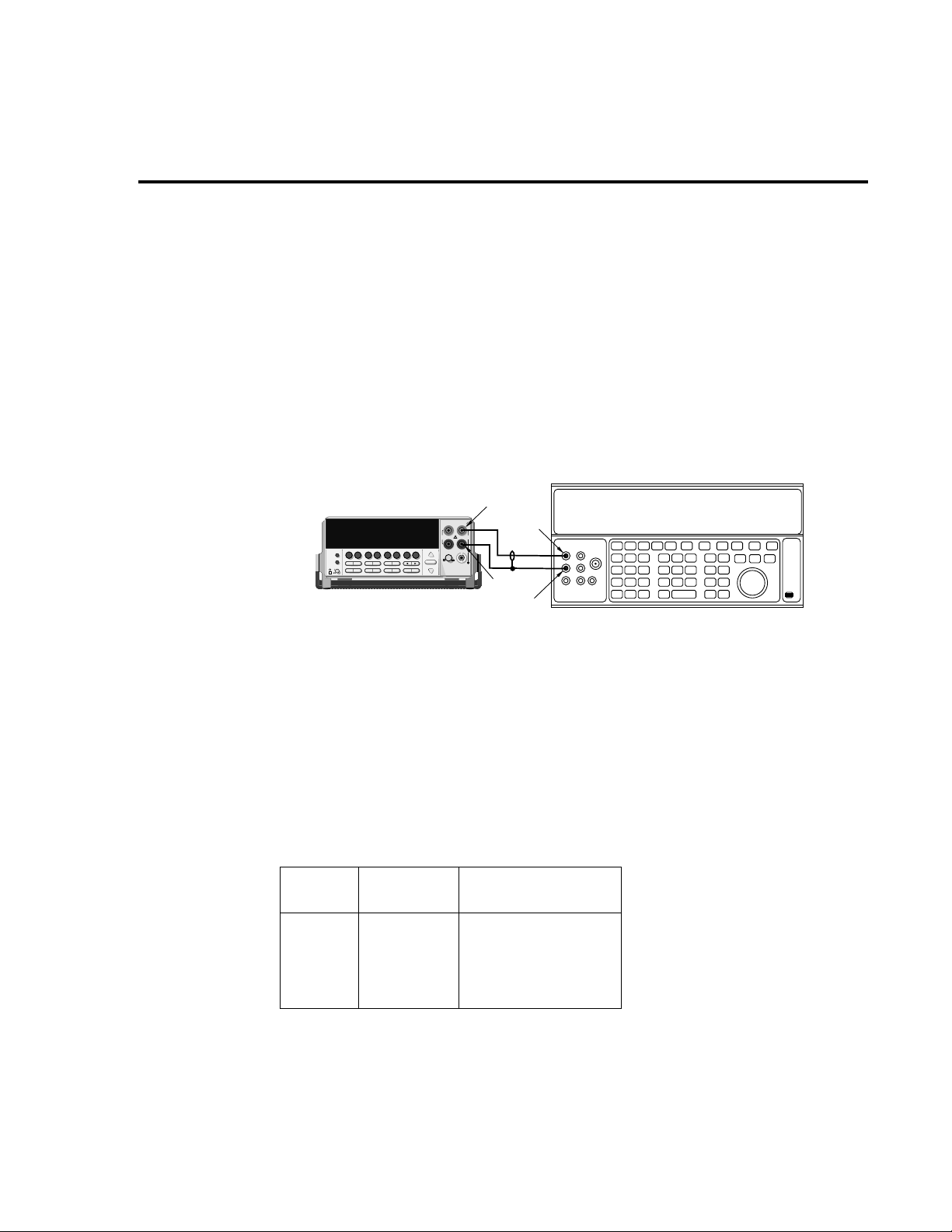
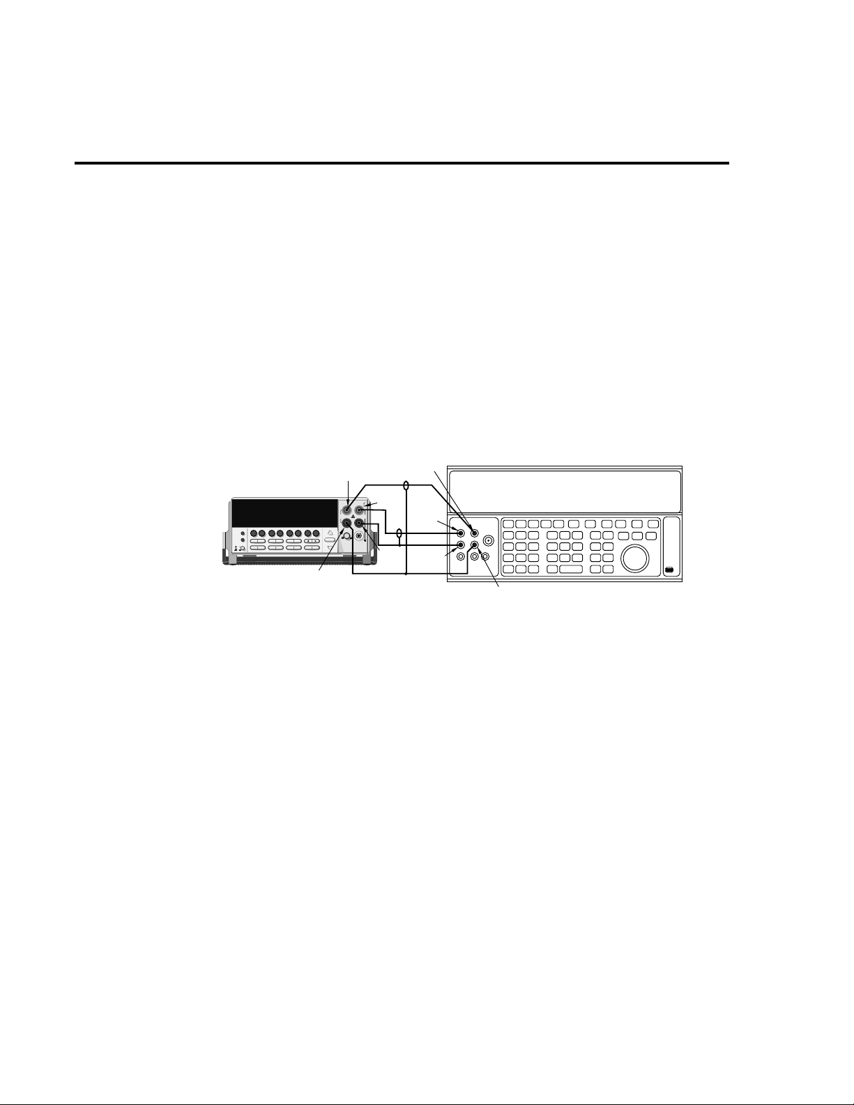
Figure 1-1
Connections for
DC volts verification
5700A Calibrator (Output DC Voltage)
Model 2000
2000 MULTIMETER
Input HI
Output HI
!
R
Input
LO
Output
LO
Note : Use shielded, low-thermal cables
for 100mV and 1V ranges.
2. Select the DC volts function by pressing the DCV key, and set the Model 2000 to the
100mV range.
3. Set the calibrator output to 0.00000mV DC, and allow the reading to settle.
4. Enable the Model 2000 REL mode. Leave REL enabled for the remainder of the DC
volts verification tests.
5. Source positive and negative full-scale voltages for each of the ranges listed in Table 1-
2. For each voltage setting, be sure that the reading is within stated limits.
Table 1-2
DCV reading limits
DCV
Range
Applied DC
voltage*
Reading limit
(1 year, 18°C-28°C)
99.9915 to 100.0085mV
0.999963 to 1.000037V
9.99965 to 10.00035V
99.9949 to 100.0051V
999.939 to 1000.061V
1V
100.0000mV
1.000000V
10.00000V
100.0000V
1000.000V
100mV
10V
100V
1000V
* Source positive and negative values for each range.
Page 17
1-8 Performance Verification
V erifying AC voltage
Check AC voltage accuracy by applying accurate AC voltages at specific frequencies from
the calibrator to the Model 2000 inputs and verifying that the display reads within specified limits.
CAUTION Do not exceed 1000 V peak between INPUT HI and INPUT LO, or 8
V•Hz input, because instrument damage may occur.
Follow these steps to verify AC voltage accuracy:
1. Connect the Model 2000 HI and LO INPUT jacks to the AC voltage calibrator as shown
in Figure 1-2.
7
×
10
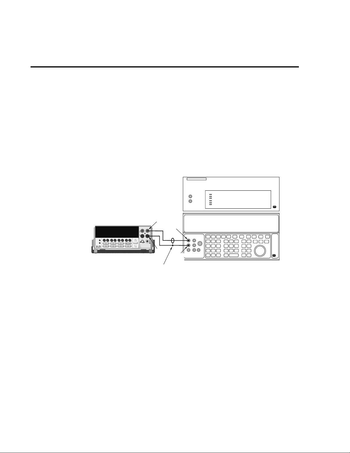
Figure 1-2
Connections for
AC volts verification
5725 Amplifier (Connect to calibrator)
Note: Amplifier required only
for 700V, 50kHz output.
Model 2000
2000 MULTIMETER
Input HI
Output HI
!
R
Input
LO
Shielded cable
Output
LO
5700A Calibrator (Output AC Voltage)
2. Select the AC volts function by pressing the ACV key.
3. Set the Model 2000 for the 100mV range; make sure that REL is disabled.
4. Source 1kHz and 50kHz AC voltages for each of the ranges summarized in Table 1-3,
and make sure that the respective Model 2000 readings fall within stated limits.
Page 18

Table 1-3
ACV reading limits
Performance Verification 1-9
ACV
Range
100mV
10V
100V
750V
*If the 5725A amplifier is not available, change the 700V @ 50kHz step to 219V @ 50kHz.
(Reading limits for 219V @ 50kHz = 218.362 to 219.638V.)
1V
Applied AC
voltage
100.0000mV
1.000000V
10.00000V
100.0000V
700.000V*
Reading limits (1 year, 18°C-28°C)
1kHz 50kHz
99.9100 to 100.0900mV
0.999100 to 1.000900V
9.99100 to 10.00900V
99.9100 to 100.0900V
699.355 to 700.645V
99.8300 to 100.1700mV
0.998300 to 1.001700V
9.98300 to 10.01700V
99.8300 to 100.1700V
698.785 to 701.215V
Page 19
1-10 Performance Verification
V erifying DC current
Check DC current accuracy by applying accurate DC currents from the calibrator to the
AMPS input of the Model 2000 and verifying that the display reads within specified limits. Follow these steps to verify DC current accuracy:
1. Connect the Model 2000 AMPS and INPUT LO jacks to the calibrator as shown in Figure 1-3.
2. Select the DC current measurement function by pressing the DCI key.
3. Set the Model 2000 for the 10mA range.
4. Source positive and negative full-scale currents for each of the ranges listed in Table 14, and verify that the readings for each range are within stated limits.
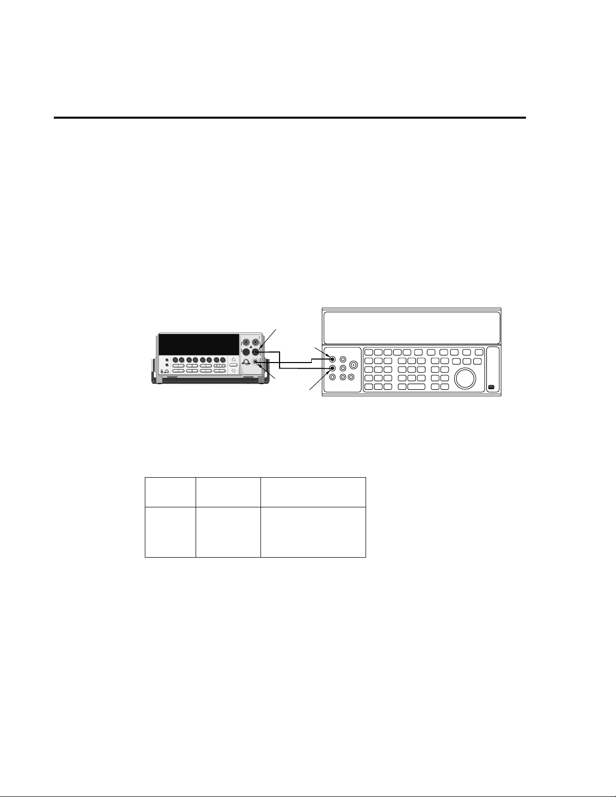
Figure 1-3
Connections for
DC current verification
Model 2000
2000 MULTIMETER
Input
LO
!
R
Output HI
Amps
Output
LO
Table 1-4
DCI limits
DCI
Range
10mA
100mA
* Source positive and negative currents with values shown.
1A
3A
Applied DC
current*
10.0000mA
100.0000mA
1.000000A
2.20000A
Reading limits
(1 year, 18°C-28°C)
9.99460 to 10.00540mA
99.9100 to 100.0900mA
0.999160 to 1.000840A
2.19732 to 2.20268A
5700A Calibrator (Output DC Current)
Note: Be sure calibrator is set for
normal current output.
Page 20
V erifying AC current
Check A C current accurac y by applying accurate AC current at specific frequencies from the
calibrator to the Model 2000 input and verifying that the display reads within specified limits.
Follow these steps to verify the AC current:
1. Connect the Model 2000 AMPS and INPUT LO jacks to the calibrator as shown in Figure 1-4.
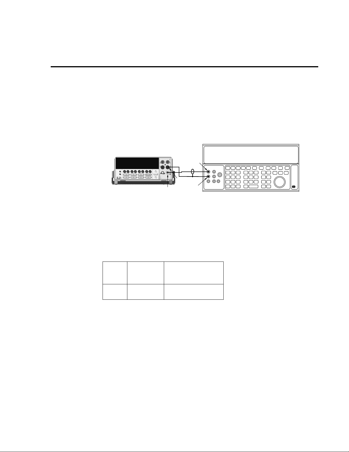
Figure 1-4
Connections for
AC current verification
Model 2000
Performance Verification 1-11
Output HI
!
2000
MULTIMETER
R
Input
LO
Amps
Output
LO
5700A Calibrator (Output AC Current)
2. Select the AC current function by pressing the ACI key.
3. Set the Model 2000 for the 1A range.
4. Source 1A and 2.2A, 1kHz AC currents as summarized in T able 1-5, and verify that the
readings are within stated limits.
Table 1-5
ACI limits
ACI
Range
1A
3A
Applied AC
current
1.000000A
2.20000A
Reading limits
(1 year, 18°C-28°C)
1kHz
0.998600 to 1.001400A
2.19490 to 2.20510A
Page 21
1-12 Performance Verification
V erifying resistance
Check resistance by connecting accurate resistance values from the calibrator to the Model
2000 and verifying that its resistance readings are within the specified limits.
Follow these steps to verify resistance accuracy:
1. Using shielded 4-wire connections, connect the Model 2000 INPUT and SENSE jacks
to the calibrator as shown in Figure 1-5.
2. Set the calibrator for 4-wire resistance with external sense on.
3. Select the Model 2000 4-wire resistance function by pressing the
4. Set the Model 2000 for the 100
5. Recalculate the limits in Table 1-6 based on actual calibrator resistance values.
6. Source the nominal full-scale resistance values for 100
Table 1-6, and verify that the readings are within stated limits.
4 key.
range, and make sure the FILTER is on.
-10M Ω ranges summarized in
Ω
Ω
Ω
Ω
Ω
Ω
Figure 1-5
Connections for
resistance verification (100
10M
Ω
ranges)
Ω
-
5700A Calibrator
Sense LO
Model 2000
2000
Sense LO
Sense HI
MULTIMETER
!
R
Sense HI
Input
HI
Output
HI
InputLOOutput
LO
Note : Use shielded low-thermal cables to
minimize noise. Enable or disable
calibrator external sense as indicated
in procedure.
7. Connect the Model 2000 INPUT and SENSE jacks to the calibrator as shown in Figure
1-6.
8. Disable external sense on the calibrator.
9. Set the Model 2000 to the 100M
10. Source a nominal 100M
the 100M
range listed in Table 1-6.
resistance value, and verify the reading is within the limits for
range.
Page 22
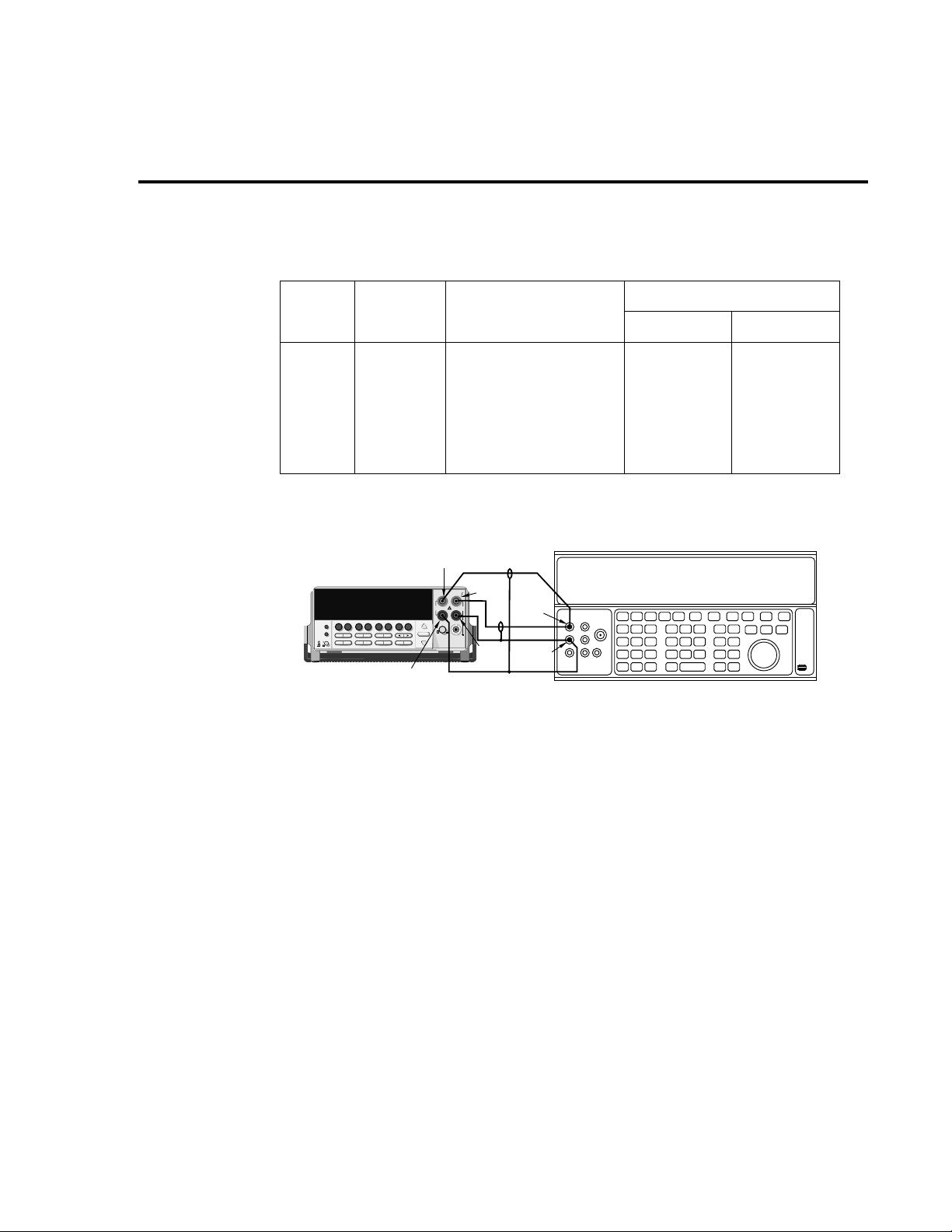
Table 1-6
Limits for resistance verification
Ω
1k Ω
Performance Verification 1-13
1M Ω
1k Ω
1M Ω
Figure 1-6
Connections for
resistance verification (100M
Ω
range)
Range
100 Ω
10k Ω
100k Ω
10M Ω
100M Ω
Nominal
applied
resistance
100 Ω
10k Ω
100k Ω
10M Ω
100M Ω
Model 2000
Sense LO
Sense HI
2000
MULTIMETER
Nominal reading limits
(1 year, 18°C-28°C)
99.9860 to 100.0140Ω
0.999890 to 1.000110kΩ
9.99890 to 10.00110kΩ
99.9890 to 100.0110kΩ
0.999890 to 1.000110MΩ
9.99590 to 10.00410MΩ
99.8470 to 100.1530MΩ
5700A Calibrator (Output 2-wire Resistance)
Input
HI
!
R
Output
HI
InputLOOutput
LO
Note : Use shielded cables to minimize noise.
Disable calibrator external sense mode.
Recalculated limits
Low limit High limit
___________
___________
___________
___________
___________
___________
___________
___________
___________
___________
___________
___________
___________
___________
Page 23

2
Calibration
Page 24

2-2 Calibration
Introduction
Use the procedures in this section to calibrate the Model 2000. Calibration procedures in-
clude:
•
Comprehensive calibration: Calibrate DC and AC voltages, DC and AC currents, and
resistance values.
•
Manufacturing calibration: Usually only performed at the factory.
W ARNING This information in this section is intended only for qualified service person-
nel. Do not attempt these procedures unless you are qualified to do so.
All the procedures require accurate calibration equipment to supply precise DC and AC voltages, DC and A C currents, and resistance v alues. Comprehensiv e A C and DC calibration can be
performed any time by a technician either from the front panel, or by using the SCPI commands
sent either over the IEEE-488 bus or the RS-232 link.
NOTE Manufacturing calibration is required in the field only if the Model 2000 has been re-
paired.
This section includes the following information:
Environmental conditions: Explains the type of environment needed for calibration.
Calibration considerations: Summarizes test conditions to observe when performing cali-
bration.
Calibration code: Explains how to enter the calibration code to unlock Model 2000 calibra-
tion.
Comprehensive calibration: Summarizes the calibration cycle and also lists recommended
comprehensive calibration equipment.
Front panel calibration: Provides the calibration procedures using the front panel.
SCPI command calibration: Provides the detailed procedures for calibrating the Model
2000 using SCPI commands.
Manufacturing calibration: Explains the manufacturing calibration procedure using both
the front panel and SCPI commands.
Page 25

Environmental conditions
Conduct the calibration procedures in a location that has:
• An ambient temperature of 23°C ±5°C
• A relative humidity of less than 80% unless otherwise noted
W arm-up period
Allow the Model 2000 Multimeter to warm up for at least one hour before performing cali-
bration.
If the instrument has been subjected to temperature extremes (those outside the ranges stated
in the above section) allow e xtra time for the instrument’ s internal temperature to stabilize. Typically, allow one extra hour to stabilize a unit that is 10°C (18°F) outside the specified temperature range.
Calibration 2-3
Also, allow the test equipment to warm up for the minimum time specified by the manufacturer.
Line power
The Model 2000 Multimeter requires a line voltage of 100V/120V/220V/240V, ±10% and a
line frequency of 45Hz to 66Hz or 360Hz to 440Hz.
Page 26

2-4 Calibration
Calibration considerations
When performing the calibration procedures:
• Make sure that the equipment is properly warmed up and connected to the appropriate
input jacks. Also make sure that the correct input jacks are selected with the INPUTS
switch.
• Make sure the calibrator is in operate before you complete each calibration step.
• Always let the source signal settle before calibrating each point.
• Do not connect test equipment to the Model 2000 through a scanner or other switching
equipment.
• If an error occurs during calibration, the Model 2000 will generate an appropriate error
message. See Section 3 and Appendix B for more information.
W ARNING The maximum common-mode voltage (voltage between INPUT LO and chas-
sis ground) is 500 V peak. Exceeding this value may cause a breakdown in
insulation, creating a shock hazard. Some of the procedures in this section
may expose you to dangerous voltages. Use standard safety precautions
when such dangerous voltages are encountered to avoid personal injury
caused by electric shock.
Page 27

Calibration code
Comprehensive calibration code
Before performing comprehensive (user) calibration, you must first unlock calibration by en-
tering the appropriate calibration code.
Front panel calibration code
For front panel calibration, follow these steps:
1. Access the calibration menu by pressing SHIFT then CAL, and note that the instrument
displays the following:
CAL: DATES
2. Use the up or do wn range keys to scroll through the av ailable calibration parameters until
the unit displays RUN, then press ENTER.
3. The Model 2000 then prompts you to enter a code. (The f actory default code is 002000.)
Use the left and right arrow keys to move among the digits; use the up range key to increment numbers, and press the down range key to specify alphabetic letters. Confirm
the code by pressing ENTER.
4. The Model 2000 allo ws you to define a new calibration code. Use the up and do wn range
keys to toggle between yes and no. Choose N if you do not want to change the code.
Choose Y if you want to change the code. The unit then prompts you to enter a ne w code.
Enter the code, and press ENTER.
Calibration 2-5
Programming the calibration code
If you are performing calibration over the IEEE-488 bus or the RS-232 link, send this com-
mand to unlock the calibration lock:
:CAL:PROT:CODE <up to 8-character string>
The default code command is:
:CAL:PROT:CODE 'KI002000'
Manufacturing calibration lock
T o unlock manufacturing calibration, press and hold the front panel OPEN k ey while turning
on the power. See Manufacturing calibration at the end of this section for procedures.
Page 28

2-6 Calibration
Comprehensive calibration
The comprehensive calibration procedure calibrates the DCV, DCI, ACV, ACI, and ohms
functions You can also choose to calibrate only DCV/DCI and resistance, or the A CV/A CI functions.
These procedures are usually the only ones required in the field. Manufacturing calibration is
done at the factory and should be done if the unit has been repaired in the field. See the Manufacturing calibration paragraph at the end of this section for more information.
Calibration cycle
Perform comprehensive calibration at least once a year, or every 90 days to ensure the unit
meets the corresponding specifications.
Recommended equipment
Table 2-1 lists the recommended equipment you need for comprehensive, DC only, and AC
only calibration procedures. You can use alternate equipment, such as a DC transfer standard
and characterized resistors, as long that equipment has specifications at least as good as those
listed in the table.
Table 2-1
Recommended equipment for comprehensive, DC only, or AC only calibration
Fluke 5700A Calibrator
DC voltage
10V: ±5ppm
100V: ±7ppm
Keithley 8610 Low-thermal shorting plug
*1kHz specifications. 10mV and 700V points require 1kHz only.
All calibration specifications are 90-day, 23° ±5°C specifications.
AC voltage
(1kHz, 50kHz)*
10mV: ±710ppm
100mV: ±200ppm
1.0V: ±82ppm
10V: ±82ppm
100V: ±90ppm
700V: ±85ppm
DC current
10mA: ±60ppm
100mA: ±70ppm
1A: ±110ppm
AC current
(1kHz)
100mA: ±190ppm
1A: ±690ppm
2A: ±670ppm
Resistance
1k
Ω : ±12ppm
10k
Ω : ±11ppm
100k
Ω : ±13ppm
1M
Ω : ±18ppm
Canceling calibration
You can cancel the calibration process at any time by pressing EXIT.
Page 29

Front panel calibration
Follow the steps in the following paragraphs for comprehensive, DC only, and AC only cali-
bration procedures.
The procedures for front panel calibration include:
• Preparing the Model 2000 for calibration
• Front panel short and open calibration
• DC voltage calibration
• Resistance calibration
• DC current calibration
• AC voltage calibration
• AC current calibration
• Setting calibration dates
Calibration 2-7
Preparing the Model 2000 for calibration
1. T urn on the Model 2000, and allo w it to warm up for at least one hour before performing
the calibration procedure.
2. Select the DCV function and choose SLOW as the RATE (integration time = 10 PLC).
3. Start the calibration process as follows:
A. Access the calibration menu by pressing SHIFT then CAL.
B. Use the up and down range keys to scroll through the available calibration menu
items until the unit displays RUN, then press ENTER.
C. At the prompt, enter the calibration code. (The default code is 002000.) Use the left
and right arrow keys to move among the digits; use the up range key to increment
numbers, and press the down range key to specify alphabetic letters. Confirm the
code by pressing ENTER.
D. Choose N at the prompt to proceed without changing the code, then press ENTER.
4. Choose which of the the calibration tests summarized in T able 2-2 you w ant to run at the
CAL: RUN prompt. Use the up and do wn range keys to scroll through the options; select
your choice by pressing ENTER.
Table 2-2
Comprehensive calibration procedures
Procedure Menu choice Procedures
Full calibration
DCV, DCI, and ohms
ACV and ACI
ALL
DC
AC
All comprehensive calibration steps.
DC voltage, DC current, and resistance calibration.
AC voltage and AC current calibration.
Page 30

2-8 Calibration
Front panel short and open calibration
Figure 2-1
Low-thermal
short connections
At the Model 2000 prompt for a front panel short, do the following:
1. Connect the Model 8610 low-thermal short to the instrument front panel INPUT and
SENSE terminals as shown in Figure 2-1. Make sure the INPUTS b utton is not pressed
in so that the front inputs are selected. Wait at least three minutes before proceeding to
allow for thermal equilibrium.
NOTE Be sure to connect the low-thermal short properly to the HI, LO, and SENSE termi-
nals. Keep drafts away from low-thermal connections to avoid thermal drift, which
could affect calibration accuracy.
Model 2000
S+ HI
2000 MULTIMETER
!
R
Model 8610
Low-thermal
short
LOS-
2. Press ENTER to start short-circuit calibration. While the unit is calibrating, the unit will
display:
CALIBRATING
3. When the unit is done calibrating, it will display the following prompt:
OPEN CIRCUIT
4. Remove the calibration short, and press ENTER. During this phase, the CALIBRATING message will be displayed.
Page 31

DC voltage calibration
After the front panel short and open procedure, the unit will prompt you for the first DC volt-
age: +10V. Do the following:
1. Connect the calibrator to the Model 2000 as sho wn in Figure 2-2. Wait three minutes to
allow for thermal equilibrium before proceeding.
NOTE Although 4-wire connections are shown, the sense leads are connected and discon-
nected at various points in this procedure by turning calibrator external sense on or
off as appropriate. If your calibrator does not have provisions for turning external
sense on and off, disconnect the sense leads when external sensing is to be turned of f ,
and connect the sense leads when external sensing is to be turned on.
Calibration 2-9
Figure 2-2
Calibrator connections for DC
volts and ohms
portion of comprehensive calibration
5700A Calibrator
Sense LO
Model 2000
2000 MULTIMETER
Sense LO
Sense HI
!
R
Sense HI
Input
HI
Output
HI
InputLOOutput
LO
Note : Use shielded low-thermal cables to
minimize noise. Enable or disable
calibrator external sense as indicated
in procedure.
2. Set the calibrator to output DC volts, and turn external sense off.
3. Perform the steps listed in Table 2-3 to complete DC volts calibration. For each calibration step:
• Set the calibrator to the indicated value, and make sure it is in operate.
• Press the ENTER key to calibrate that step.
• Wait until the Model 2000 finishes each step. (The unit will display the CALIBRAT-
ING message while calibrating.)
Page 32

2-10 Calibration
NOTE If your calibrator cannot output the values recommended in T able 2-3, use the left and
right arrow ke ys, and the up and down rang e keys to set the Model 2000 display value
to match the calibrator output voltage.
Table 2-3
DC volts calibration summary
Calibration step
+10V
-10V
100V
Resistance calibration
Completing the 100V DC calibration step ends the DC voltage calibration procedure. The
Model 2000 will then prompt you to connect 1 k
1. Set the calibrator output for resistance, and turn on external sense.
NOTE Use external sense (4-wire
the calibrator external sense mode is turned on.
2. Perform the calibration steps summarized in Table 2-4. For each step:
• Set the calibrator to the indicated value, and place the unit in operate. (If the calibrator
cannot output the exact resistance value, use the Model 2000 left and right arro w ke ys
and the range keys to adjust the Model 2000 display to agree with the calibrator resistance.)
• Press the ENTER key to calibrate each point.
• Wait for the Model 2000 to complete each step before continuing.
Calibrator
voltage
+10.00000V
-10.00000V
+100.0000V
Allowable range
+9V to +11V
-9V to -11V
+90V to +110V
Ω . Follow these steps for resistance calibration:
Ω
) when calibrating all resistance ranges. Be sure that
Table 2-4
Ohms calibration summary
Calibration step
1k Ω
10k Ω
100k Ω
1M Ω
* Nominal resistance. Adjust Model 2000 calibration parameter to
agree with actual value.
Calibrator
resistance*
1k Ω
10k Ω
100k Ω
1M Ω
Allowable range
0.9k Ω to 1.1k Ω
9k Ω to 11k Ω
90k Ω to 110k Ω
0.9M Ω to 1.1M Ω
Page 33

DC current calibration
After the 1M Ω resistance point has been calibrated, the unit will prompt you for 10mA. Fol-
low these steps for DC current calibration:
1. Connect the calibrator to the AMPS and INPUT LO terminals of the Model 2000 as
shown in Figure 2-3.
Calibration 2-11
Figure 2-3
Connections for
DC and AC amps
comprehensive
calibration
5700A Calibrator
Model 2000
2000 MULTIMETER
Input
LO
Output HI
!
R
Amps
Output
LO
Note: Be sure calibrator is set for
normal current output.
2. Calibrate each current step summarized in Table 2-5. For each step:
• Set the calibrator to the indicated DC current, and make sure the unit is in operate.
• Make sure the Model 2000 display indicates the correct calibration current.
• Press ENTER to complete each step.
• Allow the Model 2000 to finish each step.
NOTE If you are performing DC-only calibrator, proceed to the “Setting calibr ation dates”
paragraph.
Table 2-5
DC current calibration summary
Calibration step
Calibrator
current
Allowable range
10mA
100mA
1A
10.00000mA
100.0000mA
1.00000A
9mA to 11mA
90mA to 110mA
0.9A to 1.1A
Page 34

2-12 Calibration
AC voltage calibration
Figure 2-4
Connections for
AC volts calibration
Follow these steps for AC voltage calibration:
1. Connect the calibrator to the Model 2000 INPUT HI and LO terminals as shown in Figure 2-4.
5700A Calibrator
Model 2000
2000 MULTIMETER
Input HI
Output HI
!
R
Input LO
Output LO
2. Perform the calibration steps summarized in Table 2-6. For each step:
• Set the calibrator to the indicated value, and make sure the calibrator is in operate.
• Press ENTER to complete each step.
• Wait until the Model 2000 completes each step.
Table 2-6
AC voltage calibration summary
Calibration step Calibrator voltage, frequency
10mV AC at 1kHz
100mV AC at 1kHz
100mV AC at 50kHz
1V AC at 1kHz
1V AC at 50kHz
10V AC at 1kHz
10V AC at 50kHz
100V AC at 1kHz
100V AC at 50kHz
700V AC at 1kHz
10.00000mV, 1kHz
100.0000mV, 1kHz
100.0000mV, 50kHz
1.000000V, 1kHz
1.000000V, 50kHz
10.00000V, 1kHz
10.00000V, 50kHz
100.0000V, 1kHz
100.0000V, 50kHz
700.000V, 1kHz
Page 35

AC current calibration
After the 700VAC at 1kHz point has been calibrated, the unit will prompt you for 100mA at
1kHz. Follow these steps for AC current calibration:
1. Connect the calibrator to the AMPS and INPUT LO terminals of the Model 2000 as
shown in Figure 2-3.
2. Perform the calibration steps summarized in Table 2-7. For each step:
• Set the calibrator to the indicated current and frequency, and make sure the unit is in
operate.
• Press ENTER to complete each calibration step.
• Allow the unit to complete each step before continuing.
Table 2-7
AC current calibration summary
Calibration 2-13
Calibration step Calibrator voltage, frequency
100mA at 1kHz
1A at 1kHz
2A at 1kHz
Setting calibration dates
At the end of the calibration procedure, the instrument will display the CALIBRATION
COMPLETE message. Press ENTER to continue, and the the Model 2000 will prompt you to
enter the calibration date and the calibration due date. Set these dates as follows:
1. At the CAL DATE: mm/dd/yy prompt, use the left and right arrow keys, and the range
keys to set the calibration date, then press ENTER.
2. The unit will then prompt you to enter the next calibration due date with this prompt:
CAL NDUE: mm/dd/yy . Use the left and right arrow keys, and the range ke ys to set the
calibration due date, then press ENTER.
3. The unit will prompt you to save new calibration constants with this message: SAVE
CAL? YES. To save the new constants, press ENTER. If you do not want to save the
new constants, press the down range key to toggle to NO, then press ENTER.
NOTE Calibration constants calculated during the curr ent calibration pr ocedur e will not be
saved unless you choose the YES option. Previous calibration constants will be retained if you select NO.
100.0000mA, 1kHz
1.000000A, 1kHz
2.000000A, 1kHz
Page 36

2-14 Calibration
SCPI command calibration
Follow the steps in this section to use SCPI commands to perform comprehensive, DC only,
and A C only calibration procedures. See Section 3 for a detailed list and description of SCPI calibration commands.
When sending calibration commands, be sure that the Model 2000 completes each step before
sending the next command. You can do so either by observing the front panel CALIBRATING
message, or by Detecting the completion of each step over the b us. (See “Detecting calibration
step completion” at the end of Section 3.)
The procedures for calibrating the Model 2000 using SCPI commands include:
• Preparing the Model 2000 for calibration
• Front panel short and open calibration
• DC voltage calibration
• Resistance calibration
• DC current calibration
• AC voltage calibration
• AC current calibration
• Programming calibration dates
• Saving calibration constants
• Locking out calibration
NOTE As with front panel calibration, you can choose to perform complete, DC-only , or A C-
only calibration. When sending calibration commands, be sure to include a space
character between each command and parameter.
Preparing the Model 2000 for calibration
1. Connect the Model 2000 to the IEEE-488 bus of the computer using a shielded IEEE488 cable, such as the Keithley Model 7007, or connect the unit to a computer through
an RS-232 port using a straight-through 9-pin to 9-pin cable (use a 9-25-pin adapter if
necessary).
2. T urn on the Model 2000, and allow it to warm up for an hour before performing calibration.
3. Select the DCV function and choose SLOW as the RATE (integration time = 10 PLC).
4. Make sure the primary address of the Model 2000 is the same as the address specifi ed in
the program that you will be using to send commands. (Use the GPIB key.)
5. Unlock the calibration function by sending this command:
:CAL:PROT:CODE 'KI002000'
(The above command shows the default code, KI002000. Substitute the correct code if
changed.)
6. Send the following command to initiate calibration:
:CAL:PROT:INIT
Page 37

Front panel short and open calibration
1. Connect the Model 8610 lo w-thermal short to the instrument INPUT and SENSE terminals as shown in Figure 2-1. Make sure the INPUTS b utton is not pressed in so that the
front inputs are active. W ait at least three minutes before proceeding to allo w for thermal
equilibrium.
NOTE Be sure to connect the low-thermal short properly to the HI, LO, and SENSE termi-
nals. Keep drafts away from low-thermal connections to avoid thermal drift, which
could affect calibration accuracy.
2. Send the following command:
:CAL:PROT:DC:STEP1
3. After the Model 2000 completes this step, remove the short, and send this command:
:CAL:PROT:DC:STEP2
DC voltage calibration
After front panel short and open steps, do the following:
1. Connect the calibrator to the Model 2000 as shown in Figure 2-2. Allow three minutes
for thermal equilibrium.
Calibration 2-15
NOTE Although 4-wire connections are shown, the sense leads are connected and discon-
nected at various points in this procedure by turning calibrator external sense on or
off as appropriate. If your calibrator does not have provisions for turning external
sense on and off, disconnect the sense leads when external sensing is to be turned of f ,
and connect the sense leads when external sensing is to be turned on.
2. Perform the calibration steps summarized in Table 2-8. For each step:
• Set the calibrator to the indicated voltage, and make sure the unit is in operate. (Use
the recommended voltage if possible.)
• Send the indicated programming command.
• Wait until the Model 2000 completes each step before continuing.
Page 38

2-16 Calibration
Table 2-8
DC voltage calibration programming steps
Calibration
step
+10V
-10V
100V
* Change parameter accordingly if using a different calibrator voltage.
Calibrator
voltage
+10.00000V
-10.00000V
100.0000V
Resistance calibration
Follow these steps for resistance calibration:
1. Set the calibrator to the resistance mode, and turn on external sensing.
NOTE Use external sense (4-wire
the calibrator external sense mode is turned on.
2. Perform the calibration steps summarized in Table 2-9. For each step:
• Set the calibrator to the indicated resistance, and make sure the unit is in operate. (Use
the recommended resistance or the closest available value.)
• Send the indicated programming command. (Change the command parameter if you
are using a different calibration resistance than that shown.)
• Wait until the Model 2000 completes each step before continuing.
Table 2-9
Resistance calibration programming steps
Calibration command*
:CAL:PROT:DC:STEP3 10
:CAL:PROT:DC:STEP4 -10
:CAL:PROT:DC:STEP5 100
Ω
) when calibrating all resistance ranges. Be sure that
Parameter
range
9 to 11
-9 to -11
90 to 110
Calibration
step
1kΩ
10kΩ
100kΩ
1MΩ
* Use exact calibrator resistance value for parameter.
Calibrator
resistance
1kΩ
10kΩ
100kΩ
1MΩ
Calibration command*
:CAL:PROT:DC:STEP6 1E3
:CAL:PROT:DC:STEP7 10E3
:CAL:PROT:DC:STEP8 100E3
:CAL:PROT:DC:STEP9 1E6
Parameter
range
900 to 1.1E3
9E3 to 11E3
90E3 to 110E3
900E3 to 1.1E6
Page 39

DC current calibration
After the 1MΩ resistance point has been calibrated, follow these steps for DC current cali-
bration:
1. Connect the calibrator to the AMPS and INPUT LO terminals of the Model 2000 as
shown in Figure 2-3.
2. Perform the calibration steps listed in Table 2-10. For each step:
• Set the calibrator to the indicated current, and make sure the unit is in operate. (Use
the recommended current if possible.)
• Send the indicated programming command. (Change the current parameter if you are
using a different calibration current.)
• Wait until the Model 2000 completes each step before continuing.
NOTE If you are performing DC-only calibration, proceed to the “Pr ogr amming calibration
dates” paragraph.
Table 2-10
DC current calibration programming steps
Calibration 2-17
Calibration
step
10mA
100mA
1A
* Change parameter if using a different current.
Calibrator
current
10.00000mA
100.00000mA
1.000000A
Calibration command*
:CAL:PROT:DC:STEP10 10E-3
:CAL:PROT:DC:STEP11 100E-3
:CAL:PROT:DC:STEP12 1
Parameter
range
9E-3 to 11E-3
90E-3 to 110E-3
0.9 to 1.1
Page 40

2-18 Calibration
AC voltage calibration
Follow these steps for AC voltage calibration:
1. Connect the calibrator to the Model 2000 INPUT HI and LO terminals as shown in Figure 2-4.
2. Perform the calibration steps summarized in Table 2-11. For each step:
• Set the calibrator to the indicated voltage and frequency, and make sure the unit is in
operate. (You must use the stated voltage and frequency.)
• Send the indicated programming command.
• Wait until the Model 2000 completes each step before continuing.
Table 2-11
AC voltage calibration programming steps
Calibration step
10mV AC at 1kHz
100mV AC at 1kHz
100mV AC at 50kHz
1VAC at 1kHz
1VAC at 50kHz
10VAC at 1kHz
10VAC at 50kHz
100VAC at 1kHz
100VAC at 50kHz
700VAC at 1kHz
AC current calibration
Follow these steps for AC current calibration:
1. Connect the calibrator to the AMPS and INPUT LO terminals of the Model 2000 as
shown in Figure 2-3.
2. Perform the calibration steps summarized in Table 2-12. For each step:
• Set the calibrator to the indicated current and frequency, and make sure the unit is in
operate. (You must use the stated current and frequency.)
• Send the indicated programming command.
• Wait until the Model 2000 completes each step before continuing.
Calibrator voltage,
frequency
10.00000mV, 1kHz
100.0000mV, 1kHz
100.0000mV, 50kHz
1.000000V, 1kHz
1.000000V, 50kHz
10.00000V, 1kHz
10.00000V, 50kHz
100.0000V, 1kHz
100.0000V, 50kHz
700.000V, 1kHz
Calibration command
:CAL:PROT:AC:STEP1
:CAL:PROT:AC:STEP2
:CAL:PROT:AC:STEP3
:CAL:PROT:AC:STEP4
:CAL:PROT:AC:STEP5
:CAL:PROT:AC:STEP6
:CAL:PROT:AC:STEP7
:CAL:PROT:AC:STEP8
:CAL:PROT:AC:STEP9
:CAL:PROT:AC:STEP10
Page 41

Table 2-12
AC current calibration programming steps
Calibration 2-19
Calibration step
100mA at 1kHz
1A at 1kHz
2A at 1kHz
Calibrator current,
frequency
100.0000mA, 1kHz
1.000000A, 1kHz
2.000000A, 1kHz
Programming calibration dates
Program the present calibration date and calibration due date by sending the following com-
mands:
:CAL:PROT:DATE <year>, <month>, <day>
:CAL:PROT:NDUE <year>, <month>, <day>
For example, the following commands assume calibration dates of 12/15/95 and 3/14/96 re-
spectively:
:CAL:PROT:DATE 1995, 12, 15
:CAL:PROT:NDUE 1996, 3, 14
Saving calibration constants
After completing the entire calibration procedure, send the following command to save the
new calibration constants:
Calibration command
:CAL:PROT:AC:STEP11
:CAL:PROT:AC:STEP12
:CAL:PROT:AC:STEP13
:CAL:PROT:SAVE
NOTE Calibration constants will not be saved unless the :SAVE command is sent.
Locking out calibration
After saving calibration, send the following command to lock out calibration:
:CAL:PROT:LOCK
Page 42

2-20 Calibration
Manufacturing calibration
The manufacturing procedure is normally performed only at the factory, but the necessary
steps are included here in case the unit is repaired, and the unit requires these calibration procedures.
NOTE If the unit has been repaired, the entire comprehensive calibration procedure should
also be performed in addition to the manufacturing calibration procedure.
Recommended test equipment
T able 2-13 summarizes the test equipment required for the manufacuring calibration steps. In
addition, you will need the Fluke 5700A Calibrator (see Table 2-1) to complete the comprehensive calibration steps.
Table 2-13
Recommended equipment for manufacturing calibration
Keithley 3930A or 3940 Frequency Synthesizer:
1V RMS, 3Hz: ±5ppm
1V RMS, 1kHz: ±5ppm
Keithley Model 2001 or 2002 DMM:
1V, 3Hz AC, ±0.13%
Keithley Model 8610 Low-thermal shorting plug
Unlocking manufacturing calibration
To unlock manufacturing calibration, press and hold in the OPEN key while turning on the
power.
Measuring the synthesizer voltage
The 3Hz synthesizer signal amplitude must be accurately measured using the digital multimeter listed in Table 2-13. Proceed as follows:
1. Connect the synthesizer output to the digital multimeter input jacks (see Figure 2-5).
2. Turn on the synthesizer and multimeter, and allow a one-hour warm-up period before
measuring.
3. Set the synthesizer to output a 1V RMS sine wa ve at 3Hz; measure and record the signal
amplitude.
Page 43

Front panel calibration
1. Connect the low-thermal short to the rear panel input jacks, and select the rear inputs
with the INPUTS switch. Allow three minutes for thermal equilibrium.
2. Press in and hold the OPEN key while turning on the power.
3. Press SHIFT then CAL, select R UN, then enter the appropriate calibration code (default:
002000).
4. Select ALL at the CAL:RUN prompt.
5. Press ENTER.
6. Perform the entire front panel comprehensi v e calibration procedure discussed earlier in
this section.
7. Connect the synthesizer to the Model 2000 INPUT jacks as sho wn in Figure 2-5. Select
the front input jacks with the INPUTS switch.
8. After the last A C current calibration step, the instrument will prompt you to enter 3Hz at
1V RMS and 1kHz. For each prompt:
• Low frequency cal: Set the synthesizer to output a 1V RMS, 3Hz sine wa v e. Use the
left and right arrow keys, and the range keys to adjust the displayed voltage v alue to
the value you measured and recorded earlier. Press Enter.
• Frequency cal: Set the synthesizer to output a 1V RMS sine wave at 1kHz. Enter
1.000000kHz, then press ENTER.
9. Set the calibration dates, then save calibration constants to complete the process.
Calibration 2-21
Figure 2-5
Synthesizer connections for manufacturing
calibration
Model 2000
2000 MULTIMETER
!
R
BNC-to-Dual
Banana Plug
Adapter
50Ω BNC Coaxial Cable
Note: Synthesizer output voltage
must be accurately measured.
(See text).
Model 3930A or 3940 Synthesizer
Main
Function
Output
Page 44

2-22 Calibration
SCPI command calibration
1. Connect the low-thermal short to the rear panel input jacks, and select the rear inputs
with the INPUTS switch. Allow three minutes for thermal equilibrium.
2. Press in and hold the OPEN key while turning on the power.
3. Enable calibration by sending the :CODE command. F or example, the default command
is:
:CAL:PROT:CODE 'KI002000'
4. Initiate calibration by sending the following command:
:CAL:PROT:INIT
5. Calibrate step 0 with the following command:
:CAL:PROT:AC:STEP0
6. Perform the entire SCPI command comprehensive calibration procedure discussed earlier in this section.
7. Connect the synthesizer to the Model 2000 INPUT jacks as sho wn in Figure 2-5. Select
the front input jacks with the INPUTS switch.
8. Set the synthesizer output to 1V RMS at 3Hz, then send the following command:
:CAL:PROT:AC:STEP14 <Cal_voltage>
Here <Cal_voltage> is the actual 3Hz synthesizer signal amplitude you recorded earlier.
9. Set the synthesizer output to 1V RMS at 1kHz, then send the following command:
:CAL:PROT:AC:STEP15 1E3
10. Send the following commands to set calibration dates, save calibration constants, and
lock out calibration:
:CAL:PROT:DATE <year>, <month>, <day>
:CAL:PROT:NDUE <year>, <month>,<day>
:CAL:PROT:SAVE
:CAL:PROT:LOCK
NOTE After manufacturing calibration is unlocked, you have the option of performing com-
prehensive, DC-only, or AC-only calibration. If you calibrate DC-only and then lock
out calibration, manufacturing calibration is then locked, and you cannot then perform AC calibration. You must then unlock manufacturing calibration by holding in
the OPEN key and cycling power.
Page 45

3
Calibration
Command Reference
Page 46

3-2 Calibration Command Reference
Introduction
This section contains detailed information about the various Model 2000 SCPI bus calibration commands. Section 2 of this manual covers detailed calibration procedures. F or information
about additional commands to control other instrument functions, refer to the Model 2000 User's
Manual.
Page 47

Calibration Command Reference 3-3
Information in this section includes:
Command summary: Summarizes all commands necessary to perform comprehensive and
factory calibration.
Miscellaneous calibration commands: Gives detailed explanations of the various com-
mands used for miscellaneous functions such as programming the calibration code and date.
DC calibration commands: Details those commands required to calibrate the DCV, DCA,
and ohms functions.
AC calibration commands: Covers commands that calibrate Model 2000 ACV and ACI
functions.
Manufacturing calibration commands: Summarizes the commands necessary to perform
the manufacturing calibration steps.
Bus error reporting: Discusses bus calibration errors and discusses how to obtain error in-
formation.
Detecting calibration step completion: Covers how to determine when each calibration step
is completed by using the *OPC and *OPC? commands.
Page 48

Ω
Ω
Ω
Ω
3-4 Calibration Command Reference
Command summary
Table 3-1 summarizes Model 2000 calibration commands.
Table 3-1
Calibration command summary
Command Description
:CALibration
:PROTected
:CODE ‘<up to 8 char. string>’
:COUNt?
:INITiate
:LOCK
:LOCK?
:SAVE
:DATE <year>, <month>, <day>
:DATE?
:NDUE <year>, <month>, <day>
:NDUE?
:DC
:STEP0
:STEP1
:STEP2 <NRf>
:STEP3 <NRf>
:STEP4 <NRf>
:STEP5 <NRf>
:STEP6 <NRf>
:STEP7 <NRf>
:STEP8 <NRf>
:STEP9 <NRf>
:STEP10 <NRf>
:STEP11 <NRf>
:STEP12 <NRf>
Calibration root command.
All commands in this subsystem are protected
by the calibration lock (except queries and
:CODE).
Calibration code or password (default:
KI002000).
Request the number of times the unit has been
calibrated.
Initiate calibration.
Lock out calibration (opposite of enabling cal
with :CODE command).
Request comprehensive cal lock state.
(0 = locked; 1 = unlocked)
Save cal constants to EEROM.
Send cal date to 2000.
Request cal date from 2000.
Send next due cal date to 2000.
Request next due cal date from 2000.
DC cal steps.
Rear terminal short step.
Front terminal short circuit.
Open circuit.
10V DC step.
-10V DC step.
100V DC step.
1k
4-wire step.
10k
4-wire step.
100k
4-wire step.
1M
4-wire step.
10mA DC step.
100mA DC step.
1A DC step.
1
Page 49

Calibration Command Reference 3-5
Table 3-1 (cont.)
Calibration command summary
Command Description
:CALibration
Calibration root command.
:PROTected
:AC
:STEP1
:STEP2
:STEP3
:STEP4
:STEP5
:STEP6
:STEP7
:STEP8
:STEP9
:STEP10
:STEP11
:STEP12
:STEP13
:STEP14
:STEP15
NOTES:
1. DC:STEP0, AC:STEP14, and AC:STEP15 are one-time factory calibration points and are only valid in
manufacturing calibration mode.
2. Upper case letters indicated short form of each command. For example, instead of sending ":CALibration:PROTected:INITiate," you can send":CAL:PROT:INIT."
AC cal steps.
10mV AC at 1kHz step.
100mV AC at 1kHz step.
100mV AC at 50kHz step.
1V AC at 1 kHz step.
1V AC at 50kHz step.
10V AC at 1kHz step.
10V AC at 50kHz step.
100V AC at 1kHz step.
100V AC at 50kHz step.
700V AC at 1kHz step.
100mA AC at 1kHz step.
1A AC at 1kHz step.
2A AC at 1kHz step.
1V AC at 3Hz step.
1V AC at 1kHz step.
1
1
Page 50

3-6 Calibration Command Reference
Miscellaneous calibration commands
Miscellaneous commands perform calibration functions such as programming the calibration
code and date. These commands are discussed in detail in the following paragraphs.
:CODE
(:CALibration:PROT ected:CODE)
Purpose
Format
Parameter
Description
Notes
Example
:COUNt?
Purpose
Format
Response
T o program the calibration code or password so that you can perform the calibration procedures.
:cal:prot:code '<char_string>'
Up to an 8-character string including letters and numbers.
The :CODE command enables the Model 2000 calibration procedures when
performing these procedures over the bus. In general, this command must be
sent to the unit before sending any other comprehensive or manufacturing
calibration command. The default calibration code is KI002000.
• The :CODE command should be sent only once before performing either
the comprehensive or factory calibration. Do not send :CODE before each
calibration step.
• To change the code, first send the current code, then send the new code.
:CAL:PROT:CODE 'KI002000' Send default code of KI002000.
(:CALibration:PROT ected:COUNt?)
To determine how many times the Model 2000 has been calibrated.
:cal:prot:coun?
<n> Calibration count.
Description
Note
Example
The :COUNt? command allows you to determine how man y times the Model
2000 has been calibrated.
Use the COUNt? command to help you monitor for unauthorized calibration
procedures.
:CAL:PRO T:COUN? Request number of times the unit has been
calibrated.
Page 51

:INIT (:CALibration:PROT ected:INITiate)
Calibration Command Reference 3-7
:LOCK
Purpose
Format
Parameter
Description
Note
Example
(:CALibration:PROT ected:LOCK)
Purpose
Format
Parameter
Description
To initiate comprehensive and factory calibration procedures.
:cal:prot:init
None
The :INIT command enables Model 2000 calibration when performing these
procedures over the bus. This command must be sent to the unit after sending
the :CODE command, but before sending any other DC, AC, or manufacturing calibration command.
The :INIT command should be sent only once before performing either comprehensive, DC, AC, or factory calibration. Do not send :INIT before each
calibration step.
:CAL:PROT:INIT Initiate calibration.
To lock out comprehensive or manufacturing calibration.
:cal:prot:lock
None
The :LOCK command allows you to lock out both comprehensi ve and man-
ufacturing calibration after completing those procedures. Thus, :LOCK perfoms the opposite of enabling calibration with the :CODE command.
Note
Example
:LOCK?
Purpose
Format
Response
Description
Example
T o unlock comprehensi ve calibration, send the :CODE command. To unlock
manufacturing calibration, hold in the OPEN key while turning on the po wer .
:CAL:PROT:LOCK Lock out calibration.
(:CALibration:PROT ected:LOCK?)
To read comprehensive calibration lock status.
:cal:prot:lock?
0 Comprehensive calibration locked.
1 Comprehensive calibration unlocked.
The :LOCK? query requests status from the Model 2000 on calibration
locked/unlocked state. Calibration must be enabled by sending the :CODE
command before calibration can be performed.
:CAL:PROT:LOCK? Request cal lock state.
Page 52

3-8 Calibration Command Reference
:SA VE
:DA TE
(:CALibration:PROT ected:SA VE)
Purpose
Format
Parameter
Description
Note
Example
(:CALibration:PROT ected:DA TE)
Purpose
Format
Parameters
To save calibration constants in EEROM after the calibration procedure.
:cal:prot:save
None
The :SAVE command stores internally calculated calibration constants de-
rived during both comprehensi ve and manufacturing calibration in EEROM.
(EEROM is non-volatile memory.) Calibration constants will be retained indefinitely once saved. Generally, :SAVE is sent after all other calibration
steps (except for :LOCK).
Calibration will be only temporary unless the :SAVE command is sent to permanently store calibration constants.
:CAL:PROT:SAVE Save calibration constants.
To send the calibration date to the instrument.
:cal:prot:date <year>, <month>, <day>
<year> = 1994 to 2093
<month> = 1 to 12
<day> = 1 to 31
Query format
Response
Description
Note
Examples
:cal:prot:date?
<year>, <month>, <day>
The :DATE command allows you to store the calibration date in instrument
memory for future reference. You can read back the date from the instrument
over the bus by using the :DATE? query or the DATES selection in the front
panel CAL menu.
The year, month, and day parameters must be delimited by commas.
:CAL:PROT:DATE 1994, 12, 16 Send cal date (12/16/94).
:CAL:PROT:DATE? Request cal date.
Page 53

Calibration Command Reference 3-9
:NDUE
:CALibration:PROT ected:NDUE)
Purpose
Format
Parameters
Query format
Response
Description
Note
Examples
To send the next calibration due date to the instrument.
:cal:prot:ndue <year>, <month>, <day>
<year> = 1994 to 2093
<month> = 1 to 12
<day> = 1 to 31
:cal:prot:ndue?
<year>, <month>, <day>
The :NDUE command allows you to store the date when calibration is next
due in instrument memory. You can read back the next due date from the instrument over the bus by using the :NDUE? query or the front panel CAL
menu.
The next due date parameters must be delimited by commas.
:CAL:PROT:NDUE 1995,12,16 Send due date (12/16/95).
:CAL:PROT:NDUE? Request due date.
Page 54

3-10 Calibration Command Reference
DC calibration commands
The :DC commands perform comprehensive (user) calibration of the DCV, DCI, and ohms
functions. T able 3-2 summarizes these comprehensive calibration commands along with parameter limits.
Table 3-2
DC calibration commands
Ω
Ω
Ω
Ω
Command Description
:CALibration
:PROTected
:DC
:STEP1
:STEP2
:STEP3 <NRf>
:STEP4 <NRf>
:STEP5 <NRf>
:STEP6 <NRf>
:STEP7 <NRf>
:STEP8 <NRf>
:STEP9 <NRf>
:STEP10 <NRf>
:STEP11 <NRf>
:STEP12 <NRf>
Front terminal short circuit.
Open circuit.
10V DC calibration step.
-10V DC calibration step.
100V DC calibration step.
1k
4-wire calibration step.
10k
100k
1M
10mA DC calibration step.
100mA DC calibration step.
1A DC calibration step.
4-wire calibration step.
4-wire calibration step.
4-wire calibration step.
Parameter
limits
9 to 11
-9 to -11
90 to 110
900 to 1.1E3
9E3 to 11E3
90E3 to 110E3
900E3 to 1.1E6
9E-3 to 11E-3
90E-3 to 110E-3
0.9 to 1.1
Page 55

Calibration Command Reference 3-11
:STEP1
(:CALibration:PROT ected:DC:STEP1)
Purpose
Format
Parameter
Description :STEP1 performs the short-circuit calibration step in the comprehensi v e cal-
Example :CAL:PROT:DC:STEP1 Perform short-circuit calibration.
To perform front terminal short-circuit calibration.
:cal:prot:dc:step1
None
ibration procedure. Connect a low-thermal short (Model 8610) to the front
panel input jacks before sending this command.
:STEP2 (:CALibration:PROT ected:DC:STEP2)
Purpose To perform front terminal open-circuit calibration.
Format :cal:prot:dc:step2
Parameter None
Description :STEP2 performs the open-circuit calibration step in the comprehensi ve cal-
ibration procedure. Disconnect all cables and accessories from the input
jacks before sending this command.
Example :CAL:PROT:DC:STEP2 Perform open circuit calibration.
:STEP3 (:CALibration:PROT ected:DC:STEP3)
Purpose To program the +10V comprehensive calibration step.
Format :cal:prot:dc:step3 <Cal_voltage>
Parameter <Cal_voltage> = 9 to 11 [V]
Description :STEP3 programs the +10V DC comprehensive calibration step. The allow-
able range of the calibration voltage parameter is from 9 to 11, but 10 is recommended for best results.
Example :CAL:PROT:DC:STEP3 10 Program 10V step.
Page 56

3-12 Calibration Command Reference
:STEP4 (:CALibration:PROT ected:DC:STEP4)
Purpose To program the -10V DC comprehensive calibration step.
Format :cal:prot:dc:step4 <Cal_voltage>
Parameter <Cal_voltage> = -9 to -11 [V]
Description :STEP4 programs the -10V DC comprehensive calibration step. The allow-
able range of the calibration voltage parameter is from -9 to -11, but -10 is
recommended for best results.
Example :CAL:PROT:DC:STEP4 -10 Program -10V step.
:STEP5 (:CALibration:PROT ected:DC:STEP5)
Purpose To program the 100V DC comprehensive calibration step.
Format :cal:prot:dc:step5 <Cal_voltage>
Parameter <Cal_voltage> = 90 to 110 [V]
Description :STEP5 programs the 100V DC comprehensive calibration step. The allow-
able range of the calibration voltage parameter is from 90 to 110, but 100 is
recommended for best results.
Example :CAL:PROT:DC:STEP5 100 Program 100V step.
:STEP6 (:CALibration:PROT ected:DC:STEP6)
Purpose To program the 1kΩ 4-wire comprehensive calibration step.
Format :cal:prot:dc:step6 <Cal_resistance>
Parameter <Cal_resistance> = 900 to 1.1E3 [Ω]
Description :STEP6 programs the 1kΩ 4-wire resistance comprehensiv e calibration step.
The allowable range of the calibration resistance parameter is from 900 to
1.1E3 but 1E3 is recommended for best results.
Example :CAL:PROT:DC:STEP6 1E3 Program 1kΩ step.
Page 57

:STEP7 (:CALibration:PROT ected:DC:STEP7)
Purpose To program the 10kΩ 4-wire comprehensive calibration step.
Format :cal:prot:dc:step7 <Cal_resistance>
Parameter <Cal_resistance> = 9E3 to 11E3 [Ω]
Description :STEP7 programs the 10kΩ 4-wire resistance comprehensive calibration
step. The allowable range of the calibration resistance parameter is from 9E3
to 11E3, but 10E3 is recommended for best results.
Example :CAL:PROT:DC:STEP7 10E3 Program 10kΩ step.
:STEP8 (:CALibration:PROT ected:DC:STEP8)
Purpose To program the 100kΩ 4-wire comprehensive calibration step.
Format :cal:prot:dc:step8 <Cal_resistance>
Parameter <Cal_resistance> = 90E3 to 110E3 [Ω]
Description :STEP8 programs the 100kΩ 4-wire resistance comprehensive calibration
step. The allowable range of the calibration resistance parameter is from
90E3 to 110E3, but 100E3 is recommended for best results.
Calibration Command Reference 3-13
Example :CAL:PROT:DC:STEP8 100E3 Program 100kΩ step.
:STEP9 (CALibration:PROT ected:DC:STEP9)
Purpose To program the 1MΩ comprehensive calibration step.
Format :cal:prot:dc:step9 <Cal_resistance>
Parameter <Cal_resistance> = 900E3 to 1.1E6 [Ω]
Description :STEP9 programs the 1MΩ comprehensive calibration step. The allowable
range of the calibration resistance parameter is from 900E3 to 1.1E6. Use the
1E6 value whenever possible, or the closest possible value.
Example :CAL:PROT:DC:STEP9 1E6 Program 1MΩ calibration step.
Page 58

3-14 Calibration Command Reference
:STEP10 (CALibration:PROT ected:DC:STEP10)
Purpose To program the 10mA comprehensive calibration step.
Format :cal:prot:dc:step10 <Cal_current>
Parameter <Cal_current> = 9E-3 to 11E-3 [A]
Description :STEP10 programs the 10mA comprehensiv e calibration step. The allo wable
range of the calibration current parameter is from 9E-3 to 11E-3. Use the
10E-3 value whenever possible for best results.
Example :CAL:PROT:DC:STEP10 10E-3 Program 10mA step.
:STEP11 (CALibration:PROTected:DC:STEP11)
Purpose To program the 100mA comprehensive calibration step.
Format :cal:prot:dc:step11 <Cal_current>
Parameter <Cal_current> = 90E-3 to 110E-3 [A]
Description :STEP11 programs the 100mA comprehensive calibration step. The allow-
able range of the calibration current parameter is from 90E-3 to 110E-3. Use
the 100E-3 value whenever possible for best results.
Example :CAL:PROT:DC:STEP11 0.1 Program 100mA step.
:STEP12 (CALibration:PROT ected:DC:STEP12)
Purpose To program the 1A comprehensive calibration step.
Format :cal:prot:dc:step12 <Cal_current>
Parameter <Cal_current> = 0.9 to 1.1 [A]
Description :STEP12 programs the 1A comprehensive calibration step. The allowable
range of the calibration current parameter is from 0.9 to 1.1. Use a value of
1 whenever possible for best results.
Example :CAL:PROT:DC:STEP12 1 Program 1A step.
Page 59

AC calibration commands
The :AC commands perform comprehensi ve (user) calibration of the ACV and A CI functions.
Table 3-3 summarizes these comprehensive calibration commands.
Table 3-3
AC calibration commands
Command Description
:CALibration
:PROTected
:AC
:STEP
1
2
3
4
5
6
7
8
9
10
11
12
13
10mV AC at 1kHz calibration step.
100mV AC at 1kHz calibration step.
100mV AC at 50kHz calibration step.
1V AC at 1 kHz calibration step.
1V AC at 50kHz calibration step.
10V AC at 1kHz calibration step.
10V AC at 50kHz calibration step.
100V AC at 1kHz calibration step.
100V AC at 50khz calibration step.
100V AC at 1kHz calibration step.
100mA AC at 1kHz calibration step.
1A AC at 1kHz calibration step.
2A AC at 1kHz calibration step.
Calibration Command Reference 3-15
Page 60

3-16 Calibration Command Reference
:AC:STEP<n> (CALibration:PROTected:AC:STEP<n>)
Purpose To program individual AC calibration steps.
Format :cal:prot:ac:step<n>
Parameters 1 10mV AC at 1kHz calibration step.
2 100mV AC at 1kHz calibration step.
3 100mV AC at 50kHz calibration step.
4 1V AC at 1kHz calibration step.
5 1V AC at 50kHz calibration step.
6 10V AC at 1kHz calibration step.
7 10V AC at 50kHz calibration step.
8 100V AC at 1kHz calibration step.
9 100V AC at 50khz calibration step.
10 100V AC at 1kHz calibration step.
11 10mA AC at 1kHz calibration step.
12 1A AC at 1kHz calibration step.
13 2A AC at 1kHz calibration step.
Description The :AC:STEP command programs the 13 individual AC calibration steps;
<n> represents the calibration step number. The appropriate signal must be
connected to the instrument when programming each step, as summarized in
the parameters listed above.
Example :CAL:PROT:AC:STEP7 Program AC step 7.
Page 61

Calibration Command Reference 3-17
Manufacturing calibration commands
Three calibration steps are only performed at the factory or when the unit has been repaired:
:CALibration:PROTected:AC:STEP14 1V AC at 3Hz
:CALibration:PROTected:AC:STEP15 1V AC at 1kHz
:CALibration:PROTected:DC:STEP0 Rear terminal short circuit
:AC:STEP<14|15> (CALibration:PROTected:AC:STEP<14|15>)
Purpose To program individual AC manufacturing calibration steps.
Format :cal:prot:ac:step14 <Cal_voltage>
:cal:prot:ac:step15 <Cal_frequency>
Parameters <Cal_voltage> = 1 [1V nominal]
<Cal_frequency> = 1E3 [1kHz nominal]
Description The :AC:STEP command also programs the two manufacturing AC calibra-
tion steps; <n> represents the calibration step number . The appropriate signal
must be connected to the instrument when programming each step, as summarized in the parameters listed above.
Examples :CAL:PROT:AC:STEP14 1 Program AC step 14.
:CAL:PROT:AC:STEP15 1E3 Program AC Step 15.
:DC:STEP0 (:CALibration:PROT ected:DC:STEP0)
Purpose To perform rear terminal short-circuit calibration.
Format :cal:prot:dc:step0
Parameter None
Description :STEP0 performs the rear short-circuit calibration step in the manufacturing
calibration procedure. Connect a low-thermal short (Model 8610) to the rear
panel input jacks, and select the rear inputs before sending this command.
Example :CAL:PROT:DC:STEP0 Perform rear short-circuit calibration.
Page 62

3-18 Calibration Command Reference
Bus error reporting
Methods to determine calibration errors are discussed below. Refer to Appendix B for a sum-
mary of calibration errors and additional information on specific errors.
Detecting calibration errors
If an error occurs during any calibration step, the Model 2000 will generate an error message.
Several methods to detect calibration errors are discussed in the following paragraphs.
Error queue
As with other Model 2000 errors, any calibration error will be reported in the bus error queue.
Y ou can read this queue by using the :SYST :ERR? query. The Model 2000 will respond with the
appropriate error message, as summarized in Appendix B.
Status byte EA V (Error A vailable) bit
Whenever an error is available in the error queue, the EAV bit (Error Available, bit 2) of the
status byte will be set. Use the *STB? query or serial polling to obtain the status byte, then test
bit 2 to see if it is set. If the EAV bit is set, an error has occurred, and you can use the
:SYST:ERR? query to read the error and at the same time clear the EAV bit in the status byte.
Generating an SRQ on error
T o program the instrument to generate an SRQ when an error occurs, send the follo wing command: *SRE 4. This command will enable SRQ when the EAV bit is set. You can then read the
status byte and error queue as outlined above to check for errors, and so determine the e xact nature of the error.
Page 63

Calibration Command Reference 3-19
Detecting calibration step completion
When sending calibration commands over the remote interface, you must wait until the instrument completes the present operation before sending a command. You can use either *OPC?
or *OPC to help determine when each calibration step is completed.
Using the *OPC? query
With the *OPC? (operation complete) query, the instrument will place an ASCII 1 in the output queue when it has completed each step. To determine when the OPC response is ready, do
the following:
1. Repeatedly test the MAV bit (Message Available, bit 4) in the status byte, and wait until
it is set. (You can request the status byte by using the *STB? query or by serial polling.)
2. When MA V is set, a message is av ailable in the output queue, and you can read the output
queue and test for an ASCII 1.
3. After reading the output queue, repeatedly test MAV until it clears. At this point, the calibration step is completed.
Using the *OPC command
The *OPC (operation complete) command can also be used to detect the completion of each
calibration step. To use *OPC to detect the end of each calibration step, you must do the following:
1. Enable operation complete by sending *ESE 1. This command sets the OPC (operation
complete) in the standard event enable re gister, allo wing operation complete status from
the standard event status register to set the ESB (event summary bit) in the status byte
when operation complete is detected.
2. Send the *OPC command immediately following each calibration command. For example:
:CAL:PROT:DC:STEP1;*OPC
Note that you must include the semicolon (;) to separate the two commands and that the
*OPC command must appear on the same line as the calibration command.
3. After sending a calibration command, repeatedly test the ESB bit (Event Summary, bit
5) n the status byte until it is set. (Use either the *STB? query or serial polling to request
the status byte.)
4. Once operation complete has been detected, clear OPC status using one of two methods:
(1) Use the *ESR? query , then read the response to clear the standard event status register, or (2) Send the *CLS command to clear the status registers.
Note that sending *CLS will also clear the error queue and operation complete status.
Page 64

3-20 Calibration Command Reference
Generating an SRQ on calibration complete
An SRQ (service request) can be used to detect operation complete instead of repeatedly polling the Model 2000. To use this method, send both *ESE 1 and *SRE 32 to the instrument, then
include the *OPC command at the end of each calibration command line, as covered abo ve. Refer to your controller's documentation for information on detecting and servicing SRQs.
Page 65

A
Specifications
Page 66

A-2 Specifications
DC CHARACTERISTICS
CONDITIONS: MED (1 PLC)1or SLOW (10 PLC) ACCURACY:±(ppm of reading + ppm of range)
or MED (1 PLC) with filter of 10 (ppm = parts per million) (e.g.,10ppm = 0.001%)
TEMPERATURE
TEST CURRENT COEFFICIENT
OR BURDEN INPUT 24 HOUR
14
90 DAY 1 YEAR 0°–18°C &
FUNCTION RANGE RESOLUTION VOLTAGE RESISTANCE 23°C ± 1° 23°C ± 5° 23°C ±5° 28°–50°C
Voltage 100.0000 mV 0.1 µV > 10 GΩ 30 + 30 40 + 35 50 + 35 2 + 6
1.000000 V 1.0 µV > 10 GΩ 15 + 6 25 + 7 30 + 7 2 + 1
10.00000 V 10 µV > 10 GΩ 15 + 4 20 + 5 30 + 5 2 + 1
100.0000 V 100 µV 10 MΩ ±1% 15 + 6 30 + 6 45 + 6 5 + 1
1000.000 V
9
1mV 10 MΩ ±1% 20 + 6 35 + 6 45 + 6 5 + 1
Resistance15100.0000 Ω 100 µΩ 1 mA 30 + 30 80 + 40 100 + 40 8 + 6
1.000000 kΩ 1mΩ 1 mA 20 + 6 80 + 10 100 + 10 8 + 1
10.00000 kΩ 10mΩ 100 µA 20 + 6 80 + 10 100 + 10 8 + 1
100.0000 kΩ 100mΩ 10 µA 20 + 6 80 + 10 100 + 10 8 + 1
1.000000 MΩ 1 Ω 10 µA 20 + 6 80 + 10 100 + 10 8 + 1
10.00000 MΩ
11
10 Ω 700 nA // 10MΩ 150 + 6 200 + 10 400 + 10 25 + 1
100.0000 MΩ11100 Ω 700 nA // 10MΩ 800 + 30 1500 + 30 1500 + 30 150 + 1
Current 10.00000 mA 10 nA < 0.15 V 60 + 15 300 + 40 500 + 40 50 + 5
100.0000 mA 100 nA < 0.03 V 100 + 150 300 + 400 500 + 400 50 + 50
1.000000 A 1 µA < 0.3 V 200 + 15 500 + 40 800 + 40 50 + 5
3.00000 A 10 µA < 1 V 1000 + 10 1200 + 15 1200 + 15 50 + 5
Continuity 2W 1 kΩ 100mΩ 1 mA 40 + 100 100 + 100 120 + 100 8 + 1
Diode T est 3.00000 V 10 µV 1 mA 20 + 6 30 + 7 40 + 7 8 + 1
10.00000 V 10 µV 100 µA 20 + 6 30 + 7 40 + 7 8 + 1
10.00000 V 10 µV 10 µA 20 + 6 30 + 7 40 + 7 8 + 1
DC OPERATING CHARACTERISTICS
2
FUNCTION DIGITS READINGS/s PLCs
8
DCV (all ranges), 61⁄
2
3, 4
510
DCI (all ranges), and 6
1
⁄
2
3, 7
30 1
Ohms (<10M range) 61⁄
2
3, 5
50 1
5
1
⁄
2
3, 5
270 0.1
51⁄
2
5
500 0.1
5
1
⁄
2
5
1000 0.04
4
1
⁄
2
5
2000 0.01
DC SYSTEM SPEEDS
2,6
RANGE CHANGE3: 50/s.
FUNCTION CHANGE
3
: 45/s.
AUTORANGE TIME
3,10
: <30 ms.
ASCII READINGS TO RS-232 (19.2K BAUD):55/s.
MAX.INTERNAL TRIGGER RATE:2000/s.
MAX.EXTERNAL TRIGGER RATE:500/s.
DC GENERAL
LINEARITY OF 10VDC RANGE: ±(2ppm of reading + 1ppm of range).
DCV,Ω, TEMPERATURE, CONTINUITY,DIODE TEST INPUT PROTECTION: 1000V, all ranges.
MAXIMUM 4WΩ LEAD RESISTANCE:10% of range per lead for 100Ω and 1kΩ ranges; 1kΩ per lead for all other ranges.
DC CURRENT INPUT PROTECTION: 3A, 250V fuse.
SHUNT RESISTOR: 0.1Ω for 3A, 1A and 100mA ranges. 10Ωfor 10mA range.
CONTINUITY THRESHOLD: Adjustable 1Ω to 1000Ω.
AUTOZERO OFF ERROR:Add ±(2ppm of range error + 5µV ) for <10 minutes and ±1°C change.
OVERRANGE:120% of range except on 1000V, 3A and Diode.
Page 67

Specifications A-3
SPEED AND NOISE REJECTION
RMS NOISE
RATE READINGS/S DIGITS 10V RANGE NMRR12CMRR
13
10 PLC 5 61⁄
2
< 1.5 µV 60 dB 140 dB
1 PLC 50 6
1
⁄
2
< 4 µV 60 dB 140 dB
0.1 PLC 500 51⁄
2
< 22 µV — 80 dB
0.01 PLC 2000 41⁄
2
< 150 µV — 80 dB
DC Notes
1
Add the following to ppm of range accuracy specification based on range:1V and 100V, 2ppm; 100mV, 15ppm; 100Ω, 15ppm; <1MΩ, 2ppm; 10mA and 1A, 2ppm;
100mA, 20ppm.
2
Speeds are for 60 Hz operation using factory default operating conditions (*RST). Autorange off, Display off, Trigger delay = 0.
3
Speeds include measurement and binary data transfer out the GPIB.
4
Auto zero off.
5
Sample count = 1024, auto zero off.
6
Auto zero off, NPLC = 0.01.
7
Ohms = 24 readings/second.
8
1 PLC = 16.67ms @ 60Hz, 20ms @ 50Hz/400Hz. The frequency is automatically determined at power up.
9
For signal levels >500V, add 0.02ppm/V uncertainty for the por tion exceeding 500V.
10
Add 120ms for ohms.
11
Must have 10% matching of lead resistance in Input HI and LO.
12
For line frequency ±0.1%.
13
For 1kΩunbalance in LO lead.
14
Relative to calibration accuracy.
15
Specifications are for 4-wire ohms or 2-wire ohms with REL function.
TRUE RMS AC VOLTAGE AND CURRENT CHARACTERISTICS
ACCURACY1:±(% of reading + % of range), 23°C ±5 °C
VOLTAGE CALIBRATION 3 Hz– 10 Hz– 20 kHz– 50 kHz– 100 kHz–
RANGE RESOLUTION CYCLE 10 Hz 20 kHz 50 kHz 100 kHz 300 kHz
100.0000 mV 0.1 µV
1.000000 V 1.0 µV 90 Days 0.35 + 0.03 0.05 + 0.03 0.11 + 0.05 0.60 + 0.08 4 + 0.5
10.00000 V 10 µV
100.0000 V 100 µV 1 Year 0.35 + 0.03 0.06 + 0.03 0.12 + 0.05 0.60 + 0.08 4 + 0.5
750.000 V 1 mV
TEMPERATURE
COEFFICIENT
8
0.035 + 0.003 0.005 + 0.003 0.006 + 0.005 0.01 + 0.006 0.03 + 0.01
CURRENT CALIBRATION 3 Hz - 10 Hz -
RANGE RESOLUTION CYCLE 10 Hz 5 kHz
1.000000 A 1 µA 90 Day/1 Year 0.30 + 0.04 0.10 + 0.04
3.00000 A 10 µA 90 Day/1 Year 0.35 + 0.06 0.15 + 0.06
TEMPERATURE
COEFFICIENT
8
0.035 + 0.006 0.015 + 0.006
HIGH CREST FACTOR ADDITIONAL ERROR±(% of reading)
7
CREST FACTOR: 1–2 2–3 3–4 4–5
ADDITIONAL ERROR: 0.05 0.15 0.30 0.40
Page 68

A-4 Specifications
AC OPERATING CHARACTERISTICS
2
FUNCTION DIGITS READINGS/s RATE BANDWIDTH
ACV (all ranges), and 61⁄
2
3
2s/reading SLOW 3 Hz–300 kHz
ACI (all ranges) 6
1
⁄
2
3
1.4 MED 30 Hz–300 kHz
61⁄
2
4
4.8 MED 30 Hz–300 kHz
6
1
⁄
2
3
2.2 FAST 300 Hz–300 kHz
61⁄
2
4
35 FAST 300 Hz–300 kHz
ADDITIONAL LOW FREQUENCY ERRORS ±(% of reading)
SLOW MED FAST
20Hz – 30Hz 0 0.3 —
30Hz – 50Hz 0 0 —
50Hz – 100Hz 0 0 1.0
100Hz – 200Hz 0 0 0.18
200Hz – 300Hz 0 0 0.10
> 300Hz 0 0 0
AC SYSTEM SPEEDS
2,5
FUNCTION/RANGE CHANGE6: 4/s.
AUTORANGE TIME:<3 s.
ASCII READINGS TO RS-232 (19.2kBAUD)
4
: 50/s.
MAX.INTERNAL TRIGGER RATE
4
: 300/s.
MAX.EXTERNAL TRIGGER RATE
4
: 300/s.
AC GENERAL
INPUT IMPEDANCE: 1MΩ ±2% paralleled by <100pF.
ACV INPUT PROTECTION:1000Vp.
MAXIMUM DCV: 400V on any ACV range.
ACI INPUT PROTECTION:3A, 250V fuse.
BURDEN VOL TAGE: 1A Range: <0.3V rms. 3A Range: <1V rms.
SHUNT RESISTOR: 0.1Ω on all ACI ranges.
AC CMRR: >70dB with 1kΩ in LO lead.
MAXIMUM CREST FACTOR:5 at full scale.
VOLT HERTZ PRODUCT:≤8 × 10
7
V·Hz.
OVERRANGE:120% of range except on 750V and 3A ranges.
AC Notes
1
Specifications are for SLOW rate and sinewave inputs >5% of range.
2
Speeds are for 60 Hz operation using factory default operating conditions (*RST). Auto zero off, Auto range off, Display off, includes measurement and binary data
transfer out the GPIB.
3
0.01% of step settling error. Trigger delay = 400ms.
4
Trigger delay = 0.
5
DETector:BANDwidth 300, NPLC = 0.01.
6
Maximum useful limit with trigger delay = 175ms.
7
Applies to non-sinewaves >5Hz.
8
Applies to 0°–18°C and 28°–50°C.
Page 69

Specifications A-5
FREQUENCY AND PERIOD CHARACTERISTICS
1,2
RESOLUTION ACCURACY
ACV FREQUENCY PERIOD GATE ±(ppm of 90 DAY/1 YEAR
RANGE RANGE RANGE TIME reading) ±(% of reading)
100 mV 3 Hz 333 ms 1 s
to to to (SLO W) 0.3 0.01
750 V 500 kHz 2 µs
Frequency Notes
1
Specifications are for squarewave inputs >10% of ACV range, except 100mV range. On 100mV range frequency must be >10Hz if voltage is <20mV.
2
20% overrange on all ranges except 750V range.
TEMPERATURE CHARACTERISTICS
THERMOCOUPLE
2,3, 4
90 DAY/1 YEAR (23°C ±5°C)
ACCURACY
1
Relative to Using
5
TYPE RANGE RESOLUTION Reference Junction 2001-TCSCAN
J –200 to + 760°C 0.001°C ±0.5°C ±0.65°C
K –200 to +1372°C 0.001°C ±0.5°C ±0.70°C
T –200 to + 400°C 0.001°C ±0.5°C ±0.68°C
Temperature Notes
1
For temperatures <–100°C, add ±0.1°C and >900°C add ±0.3°C.
2
Temperature can be displayed in °C, K or °F.
3
Accuracy based on ITS-90.
4
Exclusive of thermocouple error.
5
Specifications apply to channels 2-6. Add 0.06°C/channel from channel 6.
INTERNAL SCANNER SPEED
4
MAXIMUM INTERNAL SCANNER RATES
RANGE: Channels/s
1
TRIGGER DELAY = 0
2-WIRE 4-WIRE
DCV
2
ACV
2,3
OHMS
2
OHMS2TEMPERATURE
2
All : 110 All : 100 All : 105 <10MΩ : 33 All : 60
TRIGGER DELAY = AUTO
2-WIRE 4-WIRE
DCV
2
ACV
2,3
OHMS
2
OHMS2TEMPERATURE
2
0.1 V : 105 All : 1.8 100 Ω : 85 100 Ω : 29 All : 60
1 V : 105 1 kΩ : 85 1 kΩ: 29
10 V : 105 10 kΩ : 42 10 kΩ : 22
100 V : 70 100 kΩ : 28 100 kΩ : 18
1000 V : 70 1 MΩ : 8 1 MΩ : 7
10 MΩ : 5 10 MΩ: 5
100 MΩ : 3 100 MΩ : 3
Internal Scanner Speed Notes
1
Speeds are for 60Hz operation using factory default operating conditions (*RST). Auto Zero off, Auto Range off, Display off, sample count = 1024.
2
NPLC = 0.01.
3
DETector:BANDwidth 300.
4
10-channel card specification. See individual card specifications for options other than 10-channel card.
Page 70

A-6 Specifications
TRIGGERING AND MEMORY
READING HOLD SENSITIVITY: 0.01%, 0.1%, 1%, or 10% of reading.
TRIGGER DELAY:0 to 99 hrs (1ms step size).
EXTERNAL TRIGGER LATENCY:200µs + <300µs jitter with autozero off, trigger delay = 0.
MEMORY:1024 readings.
MATH FUNCTIONS
Rel, Min/Max/Average/StdDev (of stored reading), dB, dBm, Limit Test, %, and mX+b with user defined units displayed.
dBm REFERENCE RESISTANCES:1 to 9999Ω in 1Ω increments.
STANDARD PROGRAMMING LANGUAGES
SCPI (Standard Commands for Programmable Instruments)
Keithley 196/199
Fluke 8840A. Fluke 8842A
REMOTE INTERFACE
GPIB (IEEE-488.1, IEEE-488.2) and RS-232C.
GENERAL SPECIFICATIONS
POWER SUPPLY: 100V / 120V / 220V / 240V ±10%.
LINE FREQUENCY:45Hz to 66Hz and 360Hz to 440Hz, automatically sensed at power-up.
POWER CONSUMPTION: 22 VA.
OPERATING ENVIRONMENT: Specified for 0°C to 50°C. Specified to 80% R.H. at 35°C.
STORAGE ENVIRONMENT: –40°C to 70°C.
WARRANTY:3 years.
SAFETY:Designed to IEC-1010.
EMI: Conforms to Class B equipment for VDE 0871, FCC part 15, CISPR 22, EN-55022.
ESD: Conforms to IEC 801-2.
VIBRATION:MIL-T-28800E Type III, Class 5.
WARMUP:1 hour to rated accuracy.
DIMENSIONS: Rack Mounting:89mm high × 213mm wide × 370mm deep (3
1
⁄2in × 83⁄8in × 149⁄16in).
Bench Configuration (with handle and feet): 104mm high × 238mm wide × 370mm deep (4
1
⁄
8
in × 9
3
⁄
8
in × 14
9
⁄
16
in).
NET WEIGHT: 2.9kg (6.3 lbs).
SHIPPING WEIGHT:5kg (11 lbs).
VOLT HERTZ PRODUCT:≤8 × 10
7
V·Hz.
Specifications are subject to change without notice.
Page 71

Specifications A-7
Accuracy calculations
The information below discusses how to calculate accuracy for both DC and AC characteris-
tics.
Calculating DC characteristics accuracy
DC characteristics accuracy is calculated as follows:
Accuracy = ±(ppm of reading + ppm of range)
(ppm = parts per million, and 10ppm = 0.001%)
As an example of how to calculate the actual reading limits, assume that you are measuring
5V on the 10V range. You can compute the reading limit range from one-year DCV accuracy
specifications as follows:
Accuracy = ±(30ppm of reading + 5ppm of range)
±[(30ppm
±(150µV + 50µV)
±200µV
Thus, the actual reading range is: 5V± 200µV, or from 4.9998V to 5.0002V
DC current and resistance calculations are performed in exactly the same manner using the
pertinent specifications, ranges, and input signal values.
× 5V) + (5ppm × 10V)]
Calculating AC characteristics accuracy
AC characteristics accuracy is calculated similarly, except that A C specifications are gi ven as
follows:
Accuracy = ±(% of reading + % of range)
As an example of how to calculate the actual reading limits, assume that you are measuring
120V, 60Hz on the 750V range. You can compute the reading limit range from ACV one-year
accuracy specifications as follows:
Accuracy = ±(0.06% of reading + 0.03% of range)
±[(0.0006
±(0.072V + 0.225V)
±0.297V
× 120V) + (0.0003 × 750V)]
In this case, the actual reading range is: 120V ± 0.297V, or from 119.703V to 120.297V
AC current calculations are performed in e xactly the same manner using the pertinent speci-
fications, ranges, and input signal values.
Page 72

A-8 Specifications
Calculating dBm characteristics accuracy
a reference impedance of 50
voltage and dBm is as follows:
0.998815V has an uncertainty of
specifications of the 1VDC range.
As an example of how to calculate the actual reading limits for a 13dBm measurement with
Ω , assume an applied signal 0.998815V. The relationship between
2
V
/ R
IN
REF
dBm = 10 log
---------------------------1mW
From the previous example on calculating DC characteristics accuracy , it can be shown that
± 36.96445 µ V, or 0.998778V to 0.998852V, using one-year
Expressing 0.998778V as dBm:
2
dBm = 10 log
0.998778V()
------------------------------------------------ - 13.00032dBm=
/ 50Ω
1mW
and expressing 0.998852V as dBm:
2
0.998852V()
dBm = 10 log
------------------------------------------------ - 13.00032dBm=
Thus, the actual reading range is 13dBm
/ 50Ω
1mW
± 0.00032dBm.
dBm and dB for other voltage inputs can be calculated in exactly the same manner using per -
tinent specifcations, ranges, and reference impedances.
Page 73

Calculating dB characteristics accuracy
The relationship between voltage and dB is as follows:
V
dB = 20 log
IN
-------------- V
REF
Specifications A-9
As an example of how to calculate the actual readings limits for dB, with a user -defined V
of 10V, you must calculate the voltage accuracy and apply it to above equation.
T o calculate a -60dB measurement, assume 10mVRMS for a V
of 10V. Using the 100mV
REF
range, one-year, 10Hz - 20kHz frequency band, and SLOW rate, the voltage limits are as follows:
Accuracy = ±[(0.06% of reading) + (0.03% of range)]
±[(0.006
× 10mV) + (0.0003 × 100mV)]
±[6µV + 30µV]
±36µV
Thus, the actual reading accuracy is 10mV
±
36 µ V or 10.036mV to 9.964mV. Applying the
voltage reading accuracy into the dB equation yields:
dBm = 20 log
dBm = 20 log
10.036mV
------------------------- -59.96879dB=
10V
9.964mV
---------------------- -60.03133dB=
10V
Thus, the actual reading accuracy is -60dB + 0.031213dB to -60dB - 0.031326dB.
dBm and dB for other voltage inputs can be calculated in exactly the same manner using per -
tinent specifications, ranges, and other reference voltages.
REF
Additional derating factors
In some cases, additional derating factors must be applied to calculate certain accuracy values. For example, an additional derating factor must be added for DC v oltages over 500V. Before
calculating accuracy , study the associated specification notes carefully to see if an y derating factors apply.
Page 74

A-10 Specifications
Optimizing measurement accuracy
The configurations listed below assume that the multimeter has had factory setups restored.
DC voltage, DC current, and resistance:
• Select 6 ½ digits, 10 PLC, filter ON (up to 100 readings), fixed range.
• Use REL on DC voltage and 2-wire resistance measurements.
• Use 4-wire resistance measurements for best accuracy.
AC voltage and AC current:
• Select 6 ½ digits, 10 PLC, filter ON (up to 100 readings), fixed range.
T emperature:
• Select 6 ½ digits, 10 PLC, filter ON (up to 100 readings).
Page 75

Optimizing measurement speed
The configurations listed below assume that the multimeter has had factory setups restored.
DC voltage, DC current, and resistance:
Select 3 ½ digits, 0.01 PLC, filter OFF, fixed range.
AC voltage and AC current:
Select 3 ½ digits, 0.01 PLC, filter OFF, fixed range.
T emperature:
Specifications A-11
• Select 3 ½ digits, 0.01 PLC, filter OFF.
For all functions, turn off the display and autozero and set the trigger delay to zero. Use the
:SAMPle:COUNt and READ? bus commands.
Page 76

A-12 Specifications
Page 77

B
Error
Messages
Page 78

B-2 Error Messages
Introduction
Errors that may occur during Model 2000 calibration are summarized in Table B-1. These errors may be requested by using the :SYST:ERR? query. The table shows the error number and
error message string as sent by the instrument.
Table B-1
Error summary
Error number Description
+400
+401
+402
+403
+404
+405
+406
+407
+408
+409
+410
+411
+412
+413
+414
+415
+416
+417
+418
+419
+420
+421
+422
+423
+424
+425
+438
+439
+450
+451
+452
+453
+454
+455
+456
+457
+458
“10 vdc zero error”
“100 vdc zero error”
“10 vdc full scale error”
“-10 vdc full scale error”
“100 vdc full scale error”
“-100 vdc full scale error”
“1k 2-w zero error”
“10k 2-w zero error”
“100k 2-w zero error”
“10M 2-w zero error”
“10M 2-w full scale error”
“10M 2-w open error”
“1k 4-w zero error”
“10k 4-w zero error”
“100k 4-w zero error”
“10M 4-w sense lo zero error”
“1k 4-w full scale error”
“10k 4-w full scale error”
“100k 4-w full scale error”
“1M 4-w full scale error”
“10M 4-w full scale error”
“10m adc zero error”
“100m adc zero error”
“10m adc full scale error”
“100m adc full scale error”
“1 adc full scale error”
“Date of calibration not set”
“Next date of calibration not set”
“100m vac dac error”
“1 vac dac error”
“10 vac dac error”
“100 vac dac error”
“100m vac zero error”
“100m vac full scale error”
“1 vac zero error”
“1 vac full scale error”
“1 vac noise error”
Page 79

Error Messages B-3
Table B-1
Error summary
Error number Description
+459
+460
+461
+462
+463
+464
+465
+466
+467
+468
+469
+470
+471
+472
+473
+500
+513
+514
+515
+610 “Questionable Calibration”
+459, “10 vac zero error”
+460, “10 vac full scale error”
+461, “10 vac noise error”
+462, “100 vac zero error”
+463, “100 vac full scale error”
+464, “750 vac zero error”
+465, “750 vac full scale error”
+466, “750 vac noise error”
+467, “Post filter offset error”
+468, “1 aac zero error”
+469, “1 aac full scale error”
+470, “3 aac zero error”
+471, “3 aac full scale error”
+472, “Input time constant error”
+473, “Frequency gain error”
“Calibration data invalid”
“AC calibration data lost”
“DC calibration data lost”
“Calibration dates lost”
Page 80

C
Calibration
Program
Page 81

C-2 Calibration Program
Introduction
This appendix includes a calibration program written in BASIC to help you calibrate the
Model 2000. Refer to Section 2 for more details on calibration procedures, equipment, and connections.
Computer hardware requirements
The following computer hardware is required to run the calibration program:
• IBM PC, AT, or compatible computer.
• Keithley KPC-488.2, KPS-488.2, or KPC-488.2A T , or CEC PC-488 IEEE-488 interf ace
for the computer.
• Two shielded IEEE-488 connecting cables (Keithley Model 7007).
Software requirements
In order to use the calibration program, you will need the following software:
• Microsoft QBasic (supplied with MS-DOS 5.0 or later).
• MS-DOS version 5.0 or later.
• HP-style Universal Language Driver , CECHP.EXE (supplied with Keithley and CEC interface cards listed above).
Calibration equipment
The following calibration equipment is required:
• Fluke 5700A Calibrator
• Keithley Model 8610 Low thermal shorting plug
See Table 2-1 in Section 2 for detailed equipment information.
Page 82

General program instructions
1. With the power off, connect the Model 2000 and the calibrator to the IEEE-488 interf ace
of the computer. Be sure to use shielded IEEE-488 cables for bus connections.
2. Turn on the computer, the Model 2000, and the calibrator . Allo w the Model 2000 and the
calibrator to warm up for at least one hour before performing calibration.
3. Make sure the Model 2002 is set for a primary address of 16. (Use the front panel GPIB
key to check or change the address.)
4. Make sure the calibrator primary address is at its factory default setting of 4.
5. Make sure that the computer bus driver software (CECHP.EXE) is properly initialized.
6. Enter the QBasic editor, and type in the program below. Check thoroughly for errors,
then save it using a convenient filename.
NOTE The progr am assumes a default calibration code of KI002000. If the calibr ation code
has been changed, modify the :CAL:PROT:CODE parameter accordingly.
Calibration Program C-3
7. Run the program, and follow the prompts on the screen to perform calibration.
Program C-1 Model 2000 calibration program
' Model 2000 calibration program for use with the Fluke 5700A calibrator.
' Rev. 1.0, 10/18/94
OPEN "IEEE" FOR OUTPUT AS #1 ' Open IEEE-488 output path.
OPEN "IEEE" FOR INPUT AS #2 ' Open IEEE-488 input path.
PRINT #1, "INTERM CRLF" ' Set input terminator.
PRINT #1, "OUTTERM LF" ' Set output terminator.
PRINT #1, "REMOTE 4 16" ' Put 2000, 5700A in remote.
PRINT #1, "CLEAR" ' Send DCL.
PRINT #1, "OUTPUT 16;:SYST:PRES;*CLS" ' Initialize 2000.
PRINT #1, "OUTPUT 16;*ESE 1;*SRE 32" ' Enable OPC and SRQ
PRINT #1, "OUTPUT 4;*RST;*CLS;STBY" ' Reset 5700A calibrator.
PRINT #1, "OUTPUT 4;CUR_POST NORMAL" ' Normal current output.
C$ = ":CAL:PROT:" ' 2000 partial command header.
'
CLS ' Clear CRT.
PRINT "Model 2000 Multimeter Comprehensive Calibration Program"
PRINT #1, "OUTPUT 16;:CAL:PROT:CODE 'KI002000'"' Send KI002000 cal code.
PRINT #1, "OUTPUT 16;:CAL:PROT:INIT" ' Initiate calibration.
GOSUB ErrCheck
RESTORE CmdList
'
FOR I = 1 TO 25 ' Loop for all cal points.
READ Msg$, Cmd$ ' Read message, cal strings.
SELECT CASE I ' Select cal sequence.
CASE 1, 2
PRINT Msg$
GOSUB KeyCheck
CASE 3
PRINT "Connect calibrator to INPUT and SENSE jacks."
PRINT "Wait 3 minutes."
GOSUB KeyCheck
PRINT #1, "OUTPUT 4;EXTSENSE OFF"
PRINT #1, "OUTPUT 4;"; Msg$
PRINT #1, "OUTPUT 4;OPER"
Page 83

C-4 Calibration Program
CASE 4, 5, 11, 12, 14 TO 22, 24 TO 25
CASE 6 TO 9
CASE 10, 13, 23
END SELECT
IF I > 2 THEN GOSUB Settle
PRINT #1, "OUTPUT 16;"; C$; Cmd$; ";*OPC" ' Send cal command to 2000.
GOSUB CalEnd ' Wait until cal step ends.
GOSUB ErrCheck ' Check for cal error.
NEXT I
'
PRINT #1, "OUTPUT 4;STBY"
LINE INPUT "Enter calibration date (yyyy,mm,dd): "; D$
PRINT #1, "OUTPUT 16;:CAL:PROT:DATE "; D$
GOSUB ErrCheck
LINE INPUT "Enter calibration due date (yyyy,mm,dd): "; D$
PRINT #1, "OUTPUT 16;:CAL:PROT:NDUE "; D$
GOSUB ErrCheck
PRINT #1, "OUTPUT 16;:CAL:PROT:SAVE" ' Save calibration constants.
GOSUB ErrCheck
PRINT #1, "OUTPUT 16;:CAL:PROT:LOCK" ' Lock out calibration.
PRINT "Calibration completed."
PRINT #1, "OUTPUT 16;:SYST:PRES"
END
'
KeyCheck: ' Check for key press routine.
WHILE INKEY$ <> "": WEND ' Flush keyboard buffer.
PRINT : PRINT "Press any key to continue (ESC to abort program)."
DO: I$ = INKEY$: LOOP WHILE I$ = ""
IF I$ = CHR$(27) THEN GOTO EndProg ' Abort if ESC is pressed.
RETURN
'
CalEnd: ' Check for cal step completion.
PRINT "Performing calibration step #"; I
DO: PRINT #1, "SRQ?" ' Request SRQ status.
INPUT #2, S ' Input SRQ status byte.
LOOP UNTIL S ' Wait for operation complete.
PRINT #1, "OUTPUT 16;*ESR?" ' Clear OPC.
PRINT #1, "ENTER 16"
INPUT #2, S
PRINT #1, "SPOLL 16" ' Clear SRQ.
INPUT #2, S
RETURN
'
ErrCheck: ' Error check routine.
PRINT #1, "OUTPUT 16;:SYST:ERR?" ' Query error queue.
PRINT #1, "ENTER 16"
INPUT #2, E, Err$
IF E <> 0 THEN PRINT Err$: GOTO ErrCheck ' Display error.
RETURN
'
Settle: ' Calibrator settling routine.
PRINT #1, "OUTPUT 4;"; Msg$
PRINT #1, "OUTPUT 4;OPER"
PRINT #1, "OUTPUT 4;"; Msg$
PRINT #1, "OUTPUT 4;EXTSENSE ON"
PRINT #1, "OUTPUT 4;OPER"
PRINT #1, "OUTPUT 4;OUT?"
PRINT #1, "ENTER 4"
INPUT #2, R, R$, S
Cmd$ = Cmd$ + " " + STR$(R)
J$ = "AMPS"
IF I = 13 THEN J$ = "INPUT HI"
PRINT #1, "OUTPUT 4;STBY"
PRINT "Connect calibrator to "; J$; " and INPUT LO jacks."
GOSUB KeyCheck
PRINT #1, "OUTPUT 4;"; Msg$
PRINT #1, "OUTPUT 4;OPER"
Page 84

Calibration Program C-5
DO: PRINT #1, "OUTPUT 4;ISR?" ' Query status register.
PRINT #1, "ENTER 4"
INPUT #2, S
LOOP UNTIL (S AND &H1000) ' Test settle bit.
RETURN
'
EndProg: ' Close files, end program.
BEEP: PRINT "Calibration aborted."
PRINT #1, "OUTPUT 4;STBY"
PRINT #1, "OUTPUT 16;:SYST:PRES"
PRINT #1, "LOCAL 4 16"
CLOSE
END
'
CmdList:
DATA "Connect low-thermal short to inputs, wait 3 minutes.","DC:STEP1"
DATA "Disconnect low-thermal short from inputs.","DC:STEP2"
DATA "OUT 10 V,0 HZ","DC:STEP3 10"
DATA "OUT -10 V","DC:STEP4 -10"
DATA "OUT 100 V","DC:STEP5 100"
DATA "OUT 1 KOHM","DC:STEP6"
DATA "OUT 10 KOHM","DC:STEP7"
DATA "OUT 100 KOHM","DC:STEP8"
DATA "OUT 1 MOHM","DC:STEP9"
DATA "OUT 10 MA","DC:STEP10 10E-3"
DATA "OUT 100 MA","DC:STEP11 100E-3"
DATA "OUT 1A","DC:STEP12 1"
DATA "OUT 10 MV,1 KHZ","AC:STEP1"
DATA "OUT 100 MV,1 KHZ","AC:STEP2"
DATA "OUT 100 MV,50 KHZ","AC:STEP3"
DATA "OUT 1 V,1 KHZ","AC:STEP4"
DATA "OUT 1 V,50 KHZ","AC:STEP5"
DATA "OUT 10 V,1 KHZ","AC:STEP6"
DATA "OUT 10 V,50 KHZ","AC:STEP7"
DATA "OUT 100 V,1 KHZ","AC:STEP8"
DATA "OUT 100 V,50 KHZ","AC:STEP9"
DATA "OUT 700 V,1 KHZ","AC:STEP10"
DATA "OUT 100 MA,1 KHZ","AC:STEP11"
DATA "OUT 1 A,1 KHZ","AC:STEP12"
DATA "OUT 2 A,1 KHZ","AC:STEP13"
Page 85

Index
Symbol
:ACSTEP <n> 3-17
:ACSTEP<14|15> 3-18
:CODE 3-6
:COUNt? 3-6
:DATE 3-8
:DCSTEP0 3-18
:INIT 3-7
:LOCK 3-7
:LOCK? 3-7
:NDUE 3-9
:SAVE 3-8
:STEP1 3-11
:STEP2 3-11
:STEP3 3-11
:STEP4 3-12
:STEP5 3-12
:STEP6 3-12
:STEP7 3-13
:STEP8 3-13
:STEP9 3-13
:STEP10 3-14
:STEP11 3-14
:STEP12 3-15
A
AC calibration commands 3-16
AC current calibration 2-13, 2-18
AC voltage calibration 2-12, 2-18
Accuracy calculations A-7
Additional derating factors A-9
B
Bus error reporting 3-19
C
Calculating AC characteristics accuracy A-7
Calculating dB characteristics accuracy A-9
Calculating dBm characteristics accuracy A-8
Calculating DC characteristics accuracy A-7
Calibration 2-1
Calibration code 2-5
Calibration Command Reference 3-1
Calibration cycle 2-6
Calibration equipment C-2
Calibration Program C-1
Canceling calibration 1-6
Command summary 3-4
Comprehensive calibration 2-6
Comprehensive calibration code 2-5
Computer hardware requirements C-2
D
DC calibration commands 3-10
DC current calibration 2-11, 2-17
DC voltage calibration 2-9, 2-15
Detecting calibration errors 3-19
Detecting calibration step completion 3-20
E
Environmental conditions 1-3, 2-3
Error Messages B-1
Error queue 3-19
Example reading limit calculation 1-5
F
Front panel calibration 2-7, 2-21
Front panel calibration code 2-5
Front panel short and open calibration 2-8, 2-15
G
General program instructions C-3
Generating an SRQ on calibration complete 3-21
Generating an SRQ on error 3-19
L
Line power 1-3, 2-3
Locking out calibration 2-19
M
Manufacturing calibration 2-20
Manufacturing calibration commands 3-18
Manufacturing calibration lock 2-5
Measuring the synthesizer voltage 2-20
Miscellaneous calibration commands 3-6
O
Optimizing measurement accuracy A-10
Optimizing measurement speed A-11
P
Performance V erification 1-1
Performing the verification test procedures 1-6
Preparing the Model 2000 for calibration 2-7, 2-14
Programming the calibration code 2-5
Programming calibration dates 2-19
R
Recommended equipment 2-6
Recommended test equipment 1-4, 2-20
Resistance calibration 2-10, 2-16
Restoring factory default 1-5
Page 86

S
Saving calibration constants 2-19
SCPI command calibration 2-14, 2-22
Setting calibration dates 2-13
Software requirements C-2
Specifications A-1
Status byte EAV (Error Available) bit 3-19
T
Test considerations 1-6
U
Unlocking manufacturing calibration 2-20
Using the *OPC command 3-20
Using the *OPC? query 3-20
V
Verification limits 1-5
Verification test requirements 1-3
Verifying AC current 1-11
Verifying AC voltage 1-8
Verifying DC current 1-10
Verifying DC voltage 1-7
Verifying resistance 1-12
W
Warm-up period 1-3, 2-3
Page 87

❑
❑
❑
❑
❑
❑
❑
❑
❑
❑
❑
❑
❑
❑
❑
❑
Service Form
Model No. _____________Serial No. _________________ Date_________________
Name and T elephone No. ________________________________________________________
Company ______________________________________________________________________
List all control settings, describe problem and check boxes that apply to problem. _________________________
__________________________________________________________________________________________
__________________________________________________________________________________________
Intermittent
IEEE failure
Front panel operational ❑ All ranges or functions are bad
Analog output follows display
Obvious problem on power-up
Particular range or function bad; specify
_______________________________
Batteries and fuses are OK
Checked all cables
Display or output (check one)
Drifts
Overload
Calibration only
(attach any additional sheets as necessary)
Show a block diagram of your measurement including all instruments connected (whether power is turned on or
not). Also, describe signal source.
Where is the measurement being performed? (factory, controlled laboratory, out-of-doors, etc.)_______________
__________________________________________________________________________________________
What power line voltage is used?___________________ Ambient temperature?________________________°F
Relative humidity? ___________________________________________Other?___________________________
Any additional information. (If special modifications have been made by the user, please describe.)
__________________________________________________________________________________________
__________________________________________________________________________________________
Be sure to include your name and phone number on this service form.
Unable to zero
Will not read applied input
Certificate of calibration required
Unstable
Data required
Page 88

Specifications are subject to change without notice.
All Keithley trademarks and trade names are the property of Keithley Instruments, Inc. All other trademarks and
trade names are the property of their respective companies.
Keithley Instruments, Inc. 28775 Aurora Road • Cleveland, Ohio 44139 • 440-248-0400 • Fax: 440-248-6168
1-888-KEITHLEY (534-8453) www.keithley.com
BELGIUM: Keithley Instruments B.V. Bergensesteenweg 709 • B-1600 Sint-Pieters-Leeuw • 02/363 00 40 • Fax: 02/363 00 64
CHINA: Keithley Instruments China
Y uan Chen Xin Building, Room 705 • 12 Yumin Road, Dewai, Madian • Beijing 100029 • 8610-6202-2886 • Fax: 8610-6202-2892
FRANCE: Keithley Instruments Sarl 3, allée des Garays • 91127 Palaiseau Cédex • 01 64 53 20 20 • Fax: 01 60 11 77 26
GERMANY: Keithley Instruments GmbH Landsberger Strasse 65 • D-82110 Germering • 089/84 93 07-40 • Fax: 089/84 93 07-34
GREAT BRITAIN: Keithley Instruments Ltd. The Minster • 58 Portman Road • Reading, Berkshire RG30 1EA • 0118-9 57 56 66 • Fax: 0118-9 59 64 69
INDIA: Keithley Instruments GmbH Flat 2B, WILLOCRISSA • 14, Rest House Crescent • Bangalore 560 001 • 91-80-509-1320/21 • Fax: 91-80-509-1322
ITALY: Keithley Instruments s.r.l. Viale San Gimignano, 38 • 20146 Milano • 02-48 39 16 01 • Fax: 02-48 30 22 74
KOREA: Keithley Instruments Korea 2FL., URI Building • 2-14 Y angjae-Dong • Seocho-Gu, Seoul 137-130 • 82-2-574-7778 • Fax: 82-2-574-7838
NETHERLANDS: Keithley Instruments B.V. Postbus 559 • NL-4200 AN Gorinchem • 0183-635333 • Fax: 0183-630821
SWITZERLAND: Keithley Instruments SA Kriesbachstrasse 4 • 8600 Dübendorf • 01-821 94 44 • Fax: 01-820 30 81
TAIWAN: Keithley Instruments Taiwan 1FL., 85 Po Ai Street • Hsinchu, Taiwan, R.O.C. • 886-3-572-9077• Fax: 886-3-572-9031
© Copyright 2000 Keithley Instruments, Inc. No. 2193
Printed in the U.S.A. 2/2000
 Loading...