

Page 1

Model 2000 Multimeter
User’s Manual
2000-900-01 Rev. J / August 2010
www.keithley.com
G
A
T
E
E
A
R
AEM
R
E
RUS
C F
O
IF
NO
ECNED
Page 2

Model 2000 Multimeter
User’s Manual
©1994-2010, Keithley Instruments, Inc.
All rights reserved.
Cleveland, Ohio, U.S.A.
Document Number: 2000-900-01 Rev. J / August 2010
Page 3

Page 4

Table of Contents
1 General Information
Feature overview..................................................................................1-2
Manual addenda ..................................................................................1-3
Safety symbols and terms....................................................................1-3
Specifications.......................................................................................1-3
Inspections...........................................................................................1-4
Options and accessories......................................................................1-5
2 Basic Measurements
Introduction ..........................................................................................2-2
Front panel summary........................................................................... 2-3
Rear panel summary............................................................................2-6
Power-up..............................................................................................2-8
Display ...............................................................................................2-17
Measuring voltage..............................................................................2-18
Measuring current ..............................................................................2-22
Measuring resistance.........................................................................2-24
Measuring frequency and period........................................................2-26
Measuring temperature......................................................................2 -28
Math...................................................................................................2-30
Measuring continuity..........................................................................2-34
Testing di odes ....................................................................................2-35
3 Measurement Options
Introduction ..........................................................................................3-2
Measurement configuration.................................................... .. ... .........3-3
Trigger operations............................................................ ....................3-8
Buffer operations............................................................................... .3-17
Limit operations.................................................................................. 3 -20
Scan operations ................................................................................. 3 -22
System operations .............................................................................3-32
4 Remote Operation
Introduction ..........................................................................................4-2
Selecting a language............................................................................4-4
RS-232 operation.................................................................................4-6
GPIB bus operation and reference.......................................................4-9
Status structure ..................................................................................4-19
Trigger model (GPIB operation).........................................................4-29
Programming syntax ............................ ... .......................................... .4-32
Common commands..........................................................................4-39
5 SCPI Command Reference
SCPI Signal oriented measurement commands ..................................5-3
SCPI command subsystems reference tables.....................................5-7
Calculate subsystem..........................................................................5-20
DISPlay subsystem............................................................................5-26
:FORMat subsystem ..........................................................................5-28
ROUTe subsystem .............................................................................5-32
[SENSe[1]] subsystem.......................................................................5-37
Page 5

STATus subsystem ............................................................................5-52
:SYSTem subsystem..........................................................................5-61
:TRACe subsystem............................................................................5-68
Trigger subsystem .............................................................................5-70
:UNIT subsystem ...............................................................................5-74
B Status and Error Messages
C Example Programs
Program examples...............................................................................C-2
D Models 196/199 and 8840A/8842A Commands
E IEEE-488 Bus Overview
Introduction..........................................................................................E-2
Bus description....................................................................................E-4
Bus lines..............................................................................................E-6
Bus commands....................................................................................E-8
Interface function codes........................................ .............................E-15
F IEEE-488 and SCPI Conformance Information
Introduction..........................................................................................F-2
Page 6

1
General
Information
Page 7

1-2 General Information
Introduction
This section contains general information about the Model 2000 Multimeter. The informa-
tion is organized as follows:
• Feature overview
• Manual addenda
• Safety symbols and terms
• Specifications
• Inspection
• Options and accessories
If you have any questions after reviewing this information, please contact your local
Keithley representative or call one of our Applications Engineers at 1-800-348-3735 (U.S.
and Canada only). Worldwide phone numbers are listed at the front of this manual.
Feature overview
The Model 2000 is a 6½-digit high-performance digital multimeter. It has 0.002% 90-day
basic DC voltage accuracy and 0.008% 90-day basic resistance accuracy. At 6½ digits, the
multimeter delivers 50 triggered readings/sec over the IEEE-488 bus. At 4½ digits, it can
read up to 2000 readings/sec into its internal buffer. The Model 2000 has broad measure
ment ranges:
-
• DC voltage from 0.1μV to 1000V.
• AC (RMS) voltage from 0.1μV to 750V, 1000V peak.
• DC current from 10nA to 3A.
• AC (RMS) current from 1μA to 3A.
• Two and four-wire resistance from 100µΩ to 120MΩ.
• Frequency from 3Hz to 500kHz.
• Thermocouple temperature from -200°C to +1372°C.
Some additional capabilities of the Model 2000 include:
• Full range of functions — In addition to those listed above, the Model 2000 functions
include period, dB, dBm, continuity, diode testing, mX+b, and percent.
• Optional scanning — For internal scanning, options include the Model 2000-SCAN,
a 10-channel, general-purpose card, and the Model 2001-TCSCAN, a 9-cha nnel,
thermocouple card with a built-in cold junction. For external scanning, the Model
2000 is compatible with Keithley's Model 7001 and 7002 switch matrices and cards.
• Programming languages and remote interfaces — The Model 2000 offers three programming language choices (SCPI, Keithley Models 196/199, and Fluke 8840A/
8842A) and two remote interface ports (IEEE-488/GPIB and RS-232C).
• Reading and setup storage — Up to 1024 readings and two setups (user and factory
defaults) can be stored and recalled.
• Closed-cover calibration — The instrument can be calibrated either from the front
panel or remote interface.
Page 8

Manual addenda
!
Any improvements or changes concerning the instrument or manual will be explained in
an addendum included with the manual. Be sure to note these changes and incorporate
them into the manual.
Safety symbols and terms
The following symbols and terms may be found on the instrument or used in this manual.
The symbol on the instrument indicates that the user should refer to the operating
instructions located in the manual.
The symbol on the instrument shows that high voltage may be present on the terminal(s). Use standard safety precautions to avoid personal contact with these voltages.
The WARNING heading used in this manual explains dangers that might result in personal injury or death. Always read the associated information very carefully before performing the indicated procedure.
The CAUTION heading used in this manual explains hazards that could damage the instrument. Such damage may invalidate the warranty.
1-3
Page 9

1-4 General Information
Inspection
The Model 2000 was carefully inspected electrically and mechanically before shipment.
After unpacking all items from the shipping carton, check for any obvious signs of physical
damage that may have occurred during transit. (Note: There may be a protective film over
the display lens, which can be removed.) Report any damage to the shipping agent imme
diately. Save the original packing carton for possible future reshipment. The following items
are included with every Model 2000 order:
• Model 2000 Multimeter with line cord.
• Safety test leads (Model 1751).
• Accessories as ordered.
• Certificate of calibration.
• Model 2000 User's Manual (P/N 2000-900-00).
• Model 2000 Calibration Manual (P/N 2000-905-00).
• Model 2000 Support Software Disk including TestPoint run-time applications,
TestPoint instrument libraries for GPIB and RS-232, and QuickBASIC examples.
If an additional manual is required, order the appropriate manual package. The manual
packages include a manual and any pertinent addenda.
-
Page 10

Options and accessories
The following options and accessories are available from Keithley for use with the Model
2000.
Scanner cards
Model 2000-SCAN: This is a 10-channel scanner card that installs in the option slot of the
Model 2000. Channels can be configured for 2-pole or 4-pole opera tion. Included are two
pairs of leads for connection to Model 2000 rear panel inputs (Keithley P/N CA-109).
Model 2001-TCSCAN: This is a thermocouple scanner card that installs in the option slot
of the Model 2000. The card has nine analog input channels that can be used for high-accuracy, high-speed scanning. A built-in temperature reference allows multi-channel, coldjunction compensated temperature measurements using thermocouples.
General purpose probes
Model 1754 Universal T est Lead Kit: Consists of one set of test leads (0.9m), two spade
lugs, two banana plugs, two hooks, and two alligator clips.
Model 8605 High Performance Modular Test Leads: Consists of two high voltage (1000V)
test probes and leads. The test leads are terminated with a banana plug with retractable
sheath on each end.
Model 8606 High Performance Probe Tip Kit: Consists of two spade lugs, two alligator
clips, and two spring hook test probes. (The spade lugs and alligator clips are rated at 30V
RMS, 42.4V peak; the test probes are rated at 1000V.) These components are for use with
high performance test leads terminated with banana plugs, such as the Model 8605.
1-5
The following test leads and probes are rated at 30V RMS, 42.4V peak:
Models 5805 and 5805-12 Kelvin Probes: Consists of two spring-loaded Kelvin test
probes with banana plug termination. Designed for instruments that measure 4-terminal
resistance. The Model 5805 is 0.9m long; the Model 5805-12 is 3.6m long.
Model 5806 Kelvin Clip Lead Set: Includes two Kelvin clip test leads (0.9m) with banana
plug termination. Designed for instruments that measure 4-terminal resistance. A set of eight
replacement rubber bands is available as Keithley P/N GA-22.
Model 8604 SMD Probe Set: Consists of two test leads (0.9m), each terminated with a
surface mount device “grabber” clip on one end and a banana plug with a retractable sheath
on the other end.
Low thermal probes
Model 8610 Low Thermal Shorting Plug: Consists of four banana plugs mounted to a 1inch square circuit board, interconnected to provide a short circuit among all plugs.
Page 11

1-6 General Information
Model 8611 Low Thermal Patch Leads: Consists of two test leads (0.9m), each with a
banana plug with a retractable sheath at each end. These leads minimize the thermallyinduced offsets that can be created by test leads.
Model 8612 Low Thermal Spade Leads: Consists of two test leads (0.9m), each terminated with a spade lug on one end and a banana plug with a retractable sheath on the other
end. These leads minimize the thermally-induced offsets that can be created by test leads.
Cables and adapters
Models 7007-1 and 7007-2 Shielded GPIB Cables: Connect the Model 2000 to the GPIB
bus using shielded cables and connectors to reduce electromagnetic interference (EMI).
The Model 7007-1 is 1m long; the Model 7007-2 is 2m long.
Models 8501-1 and 8501-2 Trigger Link Cables: Connect the Model 2000 to other instruments with Trigger Link connectors (e.g., Model 7001 Switch System). The Model 8501-1 is
1m long; the Model 8501-2 is 2m long.
Model 8502 Trigger Link Adapter: Allows you to connect any of the six Trigger Link lines
of the Model 2000 to instruments that use the standard BNC trigger connectors.
Model 8504 DIN to BNC Trigger Cable: Allows you to connect Trigger Link lines one (V oltmeter Complete) and two (External Trigger) of the Model 2000 to instruments that use BNC
trigger connectors. The Model 8504 is 1m long.
Rack mount kits
Model 4288-1 Single Fixed Rack Mount Kit: Mounts a single Model 2000 in a standard
19-inch rack.
Model 4288-2 Side-by-Side Rack Mount Kit: Mounts two instruments (Models 182, 428,
486, 487, 2000, 2001, 2002, 6517, 7001) side-by-side in a standard 19-inch rack.
Model 4288-3 Side-by-Side Rack Mount Kit: Mounts a Model 2000 and a Model 199 sideby-side in a standard 19-inch rack.
Model 4288-4 Side-by-Side Rack Mount Kit: Mounts a Model 2000 and a 5.25-inch instrument (Models 195A, 196, 220, 224, 230, 263, 595, 614, 617, 705, 740, 775, etc.) side-byside in a standard 19-inch rack.
Carrying case
Model 1050 Padded Carrying Case: A carrying case for a Model 2000. Includes handles
and shoulder strap.
Page 12

2
Basic
Measurements
Page 13

Basic Measurements
This section summarizes front panel operation of the Model 2000. It is organized as follows:
• Front panel summary — Includes an illustration and summarizes keys, display, and
connections.
• Rear panel summary — Includes an illustration and summarizes connections.
• Power-up — Describes connecting the instrument to line power, the power-up sequence, the warm-up time, and default conditions.
• Display — Discusses the display format and messages that may appear while using
the instrument.
• Measuring voltage — Covers DC and AC voltage measurement connections and low
level voltage considerations.
• Measuring current — Covers DC and AC current measurement connections and current fuse replacement.
• Measuring resistance — Details two and four-wire measurement connections and
shielding considerations.
• Measuring frequency and period — Covers frequency and period measurement connections.
• Measuring temperature — Describes the use of thermocouples for temperature measurements.
• Math — Covers the mX+b, percent, dBm, and dB math functions performed on single
readings.
• Measuring continuity — Explains setting up and measuring continuity of a circuit.
• Testing diodes — Describes testing general-purpose and zener diodes.
Page 14
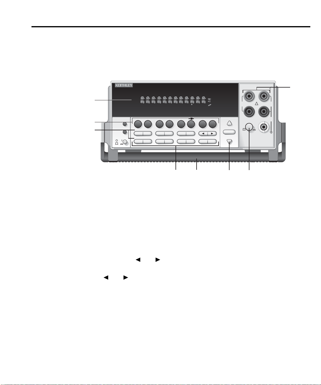
The front panel of the Model 2000 is shown in Figure 2-1. This figure includes important
8
5
4
6
7
1
3
2
2000 MULTIMETER
RANGE
!
F
500V
PEAK
FRONT/REAR
3A 250V
AMPS
HI
LO
INPUTS
350V
PEAK
1000V
PEAK
AUTO
SHIFT
LOCAL
POWER
RANGE
R
SHIFT
CH1REM
TALK
LSTN
SRQ
STAT
REL FILT
4W
BUFFER
MATH
REAR
SCAN
TIMER
STEP CH2 CH3 CH4 CH5 CH6 CH7 CH8 CH9 CH10
HOLD TRIG FAST MED SLOW AUTO ERR
INPUT
SENSE
Ω 4 WIRE
EXIT ENTER
DIGITS RATE
RELFILTER
TRIG
EX TRIG
STORE
RECALL
OPEN CLOSE
DCV
DCI
MX+B
%
dBm
ACV
ACI
Ω2 Ω4
FREQ
TEMP
dB
CONT
PERIOD TCOUPL
LIMITS ON/OFFDELAY
HOLD
SAVE SETUP
CONFIG HALT
TEST
RS232
GPIB
CAL
STEP SCAN
abbreviated information that should be reviewed before operating the instrument.
Figure 2-1
Model 2000 front
panel
1 Function keys (shifted and unshifted)
Select measurement function (DC and AC voltage, DC and AC current, 2-wire and
4-wire resistance, frequency, period, temperature with thermocouples), math func
-
tion (mX+b, %, dBm, dB), or special function (continuity, diode test).
2 Operation keys
EXTRIG Selects external triggers (front panel, bus, trigger link) as the trigger
source.
TRIG Triggers a measure m ent from the front panel.
STORE Enables reading storage.
RECALL Displays stored readings and buffer statistics (maximum, minimum, av-
erage, standard deviation). Use ▲ and ▼ to scroll through buffer; use
and to toggle between reading number and reading.
FIL TER Displays digital filter status for present function and toggles filter on/off.
REL Enables/disables relative reading on present function.
and Moves through selections within functions and operations. If scanner
card installed, manually scans channels.
OPEN Opens all channels on internal scanner card; stops scanning.
CLOSE Closes selected internal channel.
STEP Steps through channels; sends a trigger after each channel.
SCAN Scans through channels; sends a trigger after last channel.
DIGITS Changes number of digits of resolution.
RATE Changes reading rate: fast, medium, slow.
EXIT Cancels selection, moves back to measurement display.
ENTER Accepts selection, moves to next choice or back to measurement dis-
SHIFT Used to access shifted keys.
LOCAL Cancels GPIB remote mode.
play.
Page 15

3 Shifted operation keys
DELAY Sets user delay between trigger and measurement.
HOLD Holds reading when the selected number of samples is within the selected
tolerance.
LIMITS Sets upper and lower limit values for readings.
ON/OFF Enables/disables limits; selects beeper operation for limit testing.
TEST Selects built-in tests, diagnostics, display test.
CAL Accesses calibration.
SAVE Saves present configuration for power-on user default.
SETUP Restores factory or user default configuration.
CONFIG Selects minimum/maximum channels, timer, and reading count for step/
scan.
HALT Turns off step/scan.
GPIB Enables/disables GPIB interface; selects address and language.
RS232 Enables/disables RS-232 interface; select s baud rate, flo w control, termina-
tor.
4 Range keys
Moves to higher range; increments digit; moves to next selection.
Moves to lower range; decrements digit; moves to previous selection.
AUTO Enables/disables autorange.
5 Annunciators
*(asterisk) Reading being stored.
(diode) Instrument is in diode testing function.
(speaker) Beeper on for continuity or limits testing.
)))
(more) Indicates additional selections are available.
4W 4-wire resistance reading displayed.
AUTO Autoranging enabled.
BUFFER Recalling stored readings.
CH 1-10 Displayed internal channel is closed.
ERR Questionable reading; invalid cal step.
FAST Fast reading rate.
FILT Digital filter enabled.
HOLD Instrument is in hold mode.
LSTN Instrument addressed to listen over GPIB.
MATH Math function (mX+b, %, dB, dBm) enabled.
MED Medium reading rate.
REAR Reading acquired from rear inputs.
REL Relative reading displayed.
REM Instrument is in GPIB remote mode.
SCAN Instrument is in scan mode.
SHIFT Accessing shifted keys.
SLOW Slow reading rate.
SRQ Service request over GPIB.
STAT Displaying buffer statistics.
STEP Instrument is in step mode.
TALK Instrument addressed to talk over GPIB.
TIMER Timed scans in use.
TRIG Indicates external trigger (front panel, bus, trigger link) selected.
Page 16

6 Input connections
INPUT HI and LO Used for making DC volts, AC volts, 2-wire resistance measure-
ments.
AMPS Used in conjunction with INPUT LO to make DC current and AC
current measurements. Also holds current input fuse (3A, 250V ,
fast blow, 5×20mm).
SENSE Ω4 WIRE Used with INPUT HI and LO to make 4-wire resistance mea-
sure-
HI and LO ments.
7 INPUTS
Selects input connections on front or rear panel.
8 Handle
Pull out and rotate to desired position.
Page 17
Rear panel summary
WARNING:
NO INTERNAL OPERATOR SERVICABLE PARTS,SERVICE BY QUALIFIED PERSONNEL ONLY.
WARNING:
NO INTERNAL OPERATOR SERVICABLE PARTS,SERVICE BY QUALIFIED PERSONNEL ONLY.
CAUTION:
FOR CONTINUED PROTECTION AGAINST FIRE HAZARD,REPLACE FUSE WITH SAME TYPE AND RATING.
CAUTION:
FOR CONTINUED PROTECTION AGAINST FIRE HAZARD,REPLACE FUSE WITH SAME TYPE AND RATING.
RS232
1
3 5
2
4 6
VMC
EXT TRIG
FUSE LINE
250mAT
(SB)
100 VAC
120 VAC
125mAT
(SB)
220 VAC
240 VAC
120
2
1
34 5
6
#1
1
2
34
5
6
7
8
MADE IN
U.S.A.
INPUT
500V
PEAK
350V
PEAK
1000V
PEAK
TRIGGER
LINK
SENSE
Ω 4W
HI
LO
!
LINE RATING
50, 60
400HZ
17 VA MAX
IEEE-488
(CHANGE IEEE ADDRESS
FROM FRONT PANEL)
!
!
!
#2
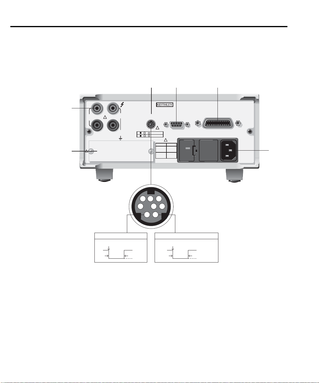
EXTERNAL TRIGGER INPUT
Trigger Reading
>72μsec
TTL HI
TTL LO
Reading
Complete
VOLT METER COMPLETE OUTPUT
>10μsec
TTL HI
TTL LO
The rear panel of the Model 2000 is shown in Figure 2-2. This figure includes important
abbreviated information that should be reviewed before operating the instrument.
Figure 2-2
Model 2000 rear
panel
Page 18

1 Option slot
An optional scanner card (Model 2000-SCAN, 2001-SCAN, or 2001-TCSCAN) installs in this slot.
2 Input connections
INPUT HI and LO Used for making DC volts, AC volts, 2-wire resistance measure-
ments and for connecting scanner card.
SENSE Ω4 WIRE Used with INPUT HI and LO to make 4-wire resistance measure-
ments
HI and LO and also for connecting scanner card.
3 TRIGGER LINK
One 8-pin micro-DIN connector for sending and receiving trigger pulses among other
instruments. Use a trigger link cable or adapter, such as Models 8501-1, 8501-2,
8502, 8504.
4 RS-232
Connector for RS-232 operation. Use a straight-through (not null modem) DB-9 cable.
5 IEEE-488
Connector for IEEE-488 (GPIB) operation. Use a shielded cable, such as Models
7007-1 and 7007-2.
6 Power module
Contains the AC line receptacle, power line fuse, and line voltage setting. The Model
2000 can be configured for line voltages of 100V/120V/220V/240VAC at line frequen
cies of 45Hz to 66Hz or 360Hz to 440Hz.
2-7
-
Page 19
Model 2000
WARNING:NO INTERNAL OPERATOR SERVICABLE PARTS,SERVICE BY QUALIFIED PERSONNEL ONLY.
WARNING:NO INTERNAL OPERATOR SERVICABLE PARTS,SERVICE BY QUALIFIED PERSONNEL ONLY.
CAUTION:FOR CONTINUED PROTECTION AGAINST FIRE HAZARD,REPLACE FUSE WITH SAME TYPE AND RATING.
CAUTION:FOR CONTINUED PROTECTION AGAINST FIRE HAZARD,REPLACE FUSE WITH SAME TYPE AND RATING.
RS232
1
3 5
2
4 6
VMC
EXT TRIG
FUSE LINE
250mAT
(SB)
100 VAC
120 VAC
125mAT
(SB)
220 VAC
240 VAC
120
MADE IN
U.S.A.
INPUT
500V
PEAK
350V
PEAK
1000V
PEAK
TRIGGER
LINK
SENSE
Ω 4W
HI
LO
!
LINE RATING
50, 60
400HZ
17 VA MAX
IEEE-488
(CHANGE IEEE ADDRESS
FROM FRONT PANEL)
!
!
!
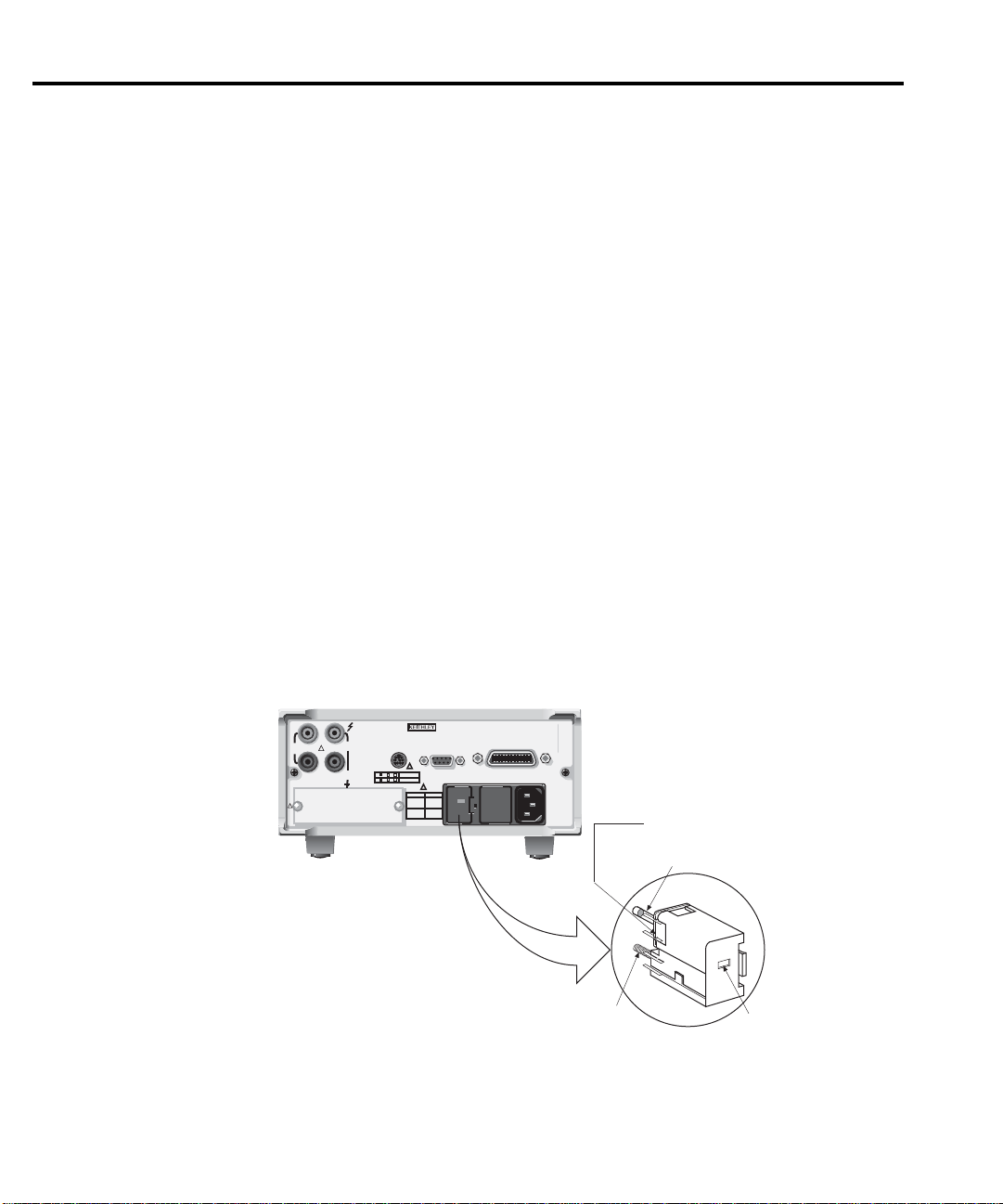
120
240
220
100
Fuse
Spring
Window
Line Voltage Selector
Fuse Holder Assembly
2-8 Basic Measurements
Power-up
Line power connection
Follow the procedure below to connect the Model 2000 to line power and turn on the
instrument.
1. Check to see that the line voltage selected on the rear panel (see Figure 2-3) is correct for the operating voltage in your area. If not, refer to the next procedure, “Setting
line voltage and replacing fuse.”
CAUTION Operating the instrument on an incorrect line voltage may cause damage to
2. Before plugging in the power cord, make sure that the front panel power switch is in
the off (0) position.
3. Connect the female end of the supplied power cord to the AC receptacle on the rear
panel. Connect the other end of the power cord to a grounded AC outlet.
WARNING The power cord supplied with the Model 2000 contains a separate ground
the instrument, possibly voiding the warranty.
wire for use with grounded outlets. When proper connections are made,
instrument chassis is connected to power line ground through the ground
wire in the power cord. Failure to use a grounded outlet may result in per
sonal injury or death due to electric shock.
-
Figure 2-3
Power module
4. Turn on the instrument by pressing the front panel power switch to the on (1) po sition.
Page 20

Setting line voltage and replacing fuse
A rear panel fuse located next to the AC receptacle protects the power line input of the
instrument. If the line voltage setting needs to be changed or the line fuse needs to be re
placed, perform the following steps.
WARNING Make sure the instrument is disconnected from the AC line and other equip-
ment before changing the line voltage setting or replacing the line fuse.
1. Place the tip of a flat-blade screwdriver into the power module by the fuse holder assembly (see Figure 2-3). Gently push in and to the left. Release pressure on the assembly and its internal spring will push it out of the power module.
2. Remove the fuse and replace it with the type listed in Table 2-1.
CAUTION For continued protection against fire or instrument damage, only replace
fuse with the type and rating listed. If the instrument repeatedly blows fuses,
locate and correct the cause of the trouble before replacing the fuse. See the
optional Model 2000 Repair Manual for troubleshooting information.
3. If configuring the instrument for a different line voltage, remove the line voltage selector from the assembly and rotate it to the proper position. When the selector is installed into the fuse holder assembly, the correct line voltage appears inverted in the
window.
4. Install the fuse holder assembly into the power module by pushing it in until it locks
in place.
2-9
-
Table 2-1
Fuse ratings
Line voltage Fuse rating Keithley P/N
100/120V
220/240V
0.25A slow-blow 5×20mm
0.125A slow-blow 5×20mm
FU-96-4
FU-91
Page 21

2-10 Basic Measurements
Power-up sequence
On power-up, the Model 2000 performs self-tests on its EPROM and RAM and momentarily lights all segments and annunciators. If a failure is detected, the instrument momentarily displays an error message and the ERR annunciator turns on. (Error messages are
listed in Appendix B.)
NOTE If a problem develops while the instrument is under warranty, return it to Keithley
If the instrument passes the self-tests, the firmware revision levels are displayed. An example of this display is:
REV: A01 A02
where: A01 is the main board ROM revision.
After the power-up sequence, the instrument begins its normal display of readings.
Instruments, Inc., for repair.
A02 is the display board ROM revision.
Page 22

High energy circuit safety precautions
To optimize safety when measuring voltage in high energy distribution circuits, read and
use the directions in the following warning.
WARNING Dangerous arcs of an explosive nature in a high energy circuit can cause
severe personal injury or death. If the multimeter is connected to a high
energy circuit when set to a current range, low resistance range, or any other
low impedance range, the circuit is virtually shorted. Dangerous arcing can
result even when the multimeter is set to a voltage range if the minimum volt
age spacing is reduced in the external connections.
When making measurements in high energy circuits, use test leads that meet the follow-
ing requirements:
• Test leads should be fully insulated.
• Only use test leads that can be connected to the circuit (e.g., alligator clips, spade
lugs, etc.) for hands-off measurements.
• Do not use test leads that decrease voltage spacing. These diminishes arc protection and create a hazardous condition.
Use the following sequence when testing power circuits:
1. De-energize the circuit using the regular installed connect-disconnect device, such
as a circuit breaker, main switch, etc.
2. Attach the test leads to the circuit under test. Use appropriate safety rated test leads
for this application.
3. Set the multimeter to the proper function and range.
4. Energize the circuit using the installed connect-disconnect device and make measurements without disconnecting the multimeter.
5. De-energize the circuit using the installed connect-disconnect device.
6. Disconnect the test leads from the circuit under test.
-
WARNING The maximum common-mode voltage (voltage between INPUT LO and the
chassis ground) is 500V peak. Exceeding this value may cause a breakdown
in insulation, creating a shock hazard.
Page 23

Power-on defaults
Power-on defaults are the settings the instrument assumes when it is turned on. The
Model 2000 offers two choices for the settings: factory and user. The power-on default will
be the last configuration you saved. The SAVE and SETUP keys select the two choices of
power-on defaults.
To save presen t configuration as user settings:
1. Configure the instrument as desired for USER default.
2. Press SHIFT then SAVE.
3. Use the ▲ and ▼ keys to select YES or NO.
4. Press ENTER.
To restore factory or user settings:
1. Press SHIFT then SETUP.
2. Use the ▲ and ▼ keys to select FACTory or USER.
3. Press ENTER.
Since the basic measurement procedures in this manual assume the factory defaults, reset the instrument to the factory settings when following step-by-step procedures. Table 2-2
lists the factory default settings.
Page 24

Table 2-2
Factory defaults
Setting Factory default
Autozero
Buffer
Continuity
Beeper
Digits
Rate
Threshold
Current (AC and DC)
Digits (AC)
Digits (DC)
Filter
Count
Mode
Range
Relative
Value
Rate (AC)
Rate (DC)
Diode test
Digits
Range
Rate
Frequency and Period
Digits
Range
Relative
Value
Rate
Function
GPIB
Address
Language
Limits
Beeper
High limit
Low limit
mX+b
Scale factor
Offset
Percent
References
On
No effect
On
4½
Fast (0.1 PLC)
10Ω
5½
6½
On
10
Moving average
Auto
Off
0.0
Medium (DETector BANDwidth 30)
Medium (1 PLC)
6½
1mA
Medium (1 PLC)
6½
10V
Off
0.0
Slow (1 sec)
DCV
No effect
(16 at factory)
(SCPI at factory)
Off
Never
+1
-1
Off
1.0
0.0
Off
1.0
Page 25

Table 2-2 (cont.)
Factory defaults
Setting Factory default
Resistance (2-wire and 4-wire)
Digits
Filter
Count
Mode
Range
Relative
Value
Rate
RS-232
Baud
Flow
Tx term
Scanning
Channels
Mode
6½
On
10
Moving average
Auto
Off
0.0
Medium (1 PLC)
Off
No effect
No effect
No effect
Off
1-10
Internal
Temperature
Digits
Filter
Count
Mode
Junction
Temperature
Relative
Value
Rate
Thermocouple
Units
5½
On
10
Moving average
Simulated
23°C
Off
0.0
Medium (1 PLC)
J
°C
Triggers
Continuous
Delay
Source
On
Auto
Immediate
Page 26

Table 2-2 (cont.)
Factory defaults
Setting Factory default
Voltage (AC and DC)
dB reference
dBm reference
Digits (AC)
Digits (DC)
Filter
Count
Mode
Range
Relative
Value
Rate (AC)
Rate (DC)
No effect
75Ω
5½
6½
On
10
Moving average
Auto
Off
0.0
Medium*
Medium (1 PLC)
Page 27

GPIB primary address
The GPIB primary address of the instrument must be the same as the primary address
you specify in the controller’s programming language. The default primary address of the
instrument is 16, but you can set the address to any value from 0 to 30 by using the following
step by step instructions.
1. Press SHIFT then GPIB.
2. Use the and keys to select ADDRess. Or, press ENTER. Once you have
pressed ENTER, the unit automatically displays the address selection.
3. Use the and keys to toggle from ADDRess to the numeric entry. Notice the
values are blinking.
4. Use the and keys to change the numeric entries to the desired address.
5. Press ENTER.
See Section Four — Remote Operation for more GPIB information.
Warm-up time
The Model 2000 is ready for use as soon as the power-up sequence has completed.
However, to achieve rated accuracy, all ow the instrument to warm up for one hour. If the
instrument has been subjected to extreme temperatures, allow additional time for internal
temperatures to stabilize.
Page 28

Display
Status and error messages
The display of the Model 2000 is primarily used to display readings, along with the units
and type of measurement. Annunciators are located on the top, bottom, right, and left of the
reading or message display. The annunciators indicate various states of operation. See Fig
ure 2-1 for a complete listing of annunciators.
Status and error messages are displayed momentarily . During Model 2000 operation and
programming, you will encounter a number of front panel messages. Typical messages are
either of status or error variety, as listed in Appendix B.
-
Page 29

Measuring voltage
The Model 2000 can make DCV measurements from 0.1µV to 1000V and ACV measure-
ments from 0.1µV to 750V RMS, 1000V peak.
Connections
Assuming factory default conditions, the basic procedure is as follows:
1. Connect test leads to the INPUT HI and LO terminals. Either the front or rear inputs
can be used; place the INPUTS button in the appropriate position.
2. Select the measurement function by pressing DCV or ACV.
Pressing AUTO toggles autoranging. Notice the AUTO annunciator is displayed with
autoranging. If you want manual ranging, use the RANGE and keys to select
a measurement range consistent with the expected voltage.
4. Connect test leads to the source as shown in Figure 2-4.
CAUTION Do not apply more than 1000V peak to the input or instrument damage may
occur. The voltage limit is subject to the 8 × 10⁷V•Hz product.
5. Observe the display. If the “OVERFLOW” message is displayed, select a higher
range until an o normal reading is displayed (or press AUTO for autoranging). Use
the lowest possible range for the best resolution.
6. Take readings from the display.
Crest factor
AC voltage and current accuracies are affected by the crest factor of the waveform, the
ratio of the peak value to the RMS value. Table 2-3 lists the fundamental frequencies at
which the corresponding crest factor must be taken into account for accuracy calculations.
Table 2-3
Crest factor limitations
Crest factor Fundamental frequency
2
3
4-5
50kHz
3kHz
1kHz
Page 30
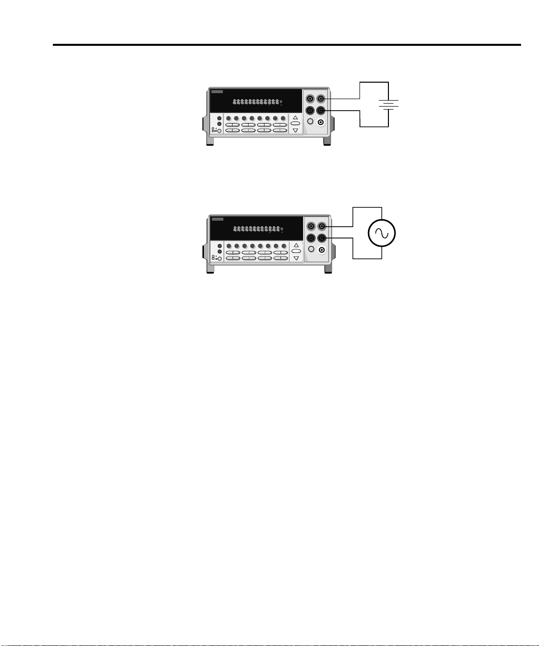
2001 MULTIMETER
Caution: Maximum Input = 750V RMS, 1000V peak, 8 x 10⁷ V•Hz
AC Voltage
Source
Model 2000
Input Impedence = 1MΩ and 100pF
SHIFT
CH1REM
TALK
LSTN
SRQ
STATREL FILT4WBUFFER
MATH
REAR
SCAN
TIMER
STEP CH2 CH3 CH4 CH5 CH6 CH7 CH8CH9 CH1
0
HOLD TRIG FAST MED SLOW AUTO ERR
2001 MULTIMETER
Model 2000
Caution : Maximum Input = 1010V peak
DC Voltage
Source
Input Resistance = 10MΩ on 1000V and 100V ranges ;
> 10GΩ on 10V, 1V and 100mV ranges.
SHIFT
CH1REM
TALK
LSTN
SRQ
STATREL FILT4WBUFFER
MATH
REAR
SCAN
TIMER
STEP CH2 CH3 CH4 CH5 CH6 CH7 CH8 CH9 CH10
HOLD TRIG FAST MED SLOW AUTO ERR
Figure 2-4
DC and AC voltage measurements
Low level considerations
For sensitive measurements, external considerations beyond the Model 2000 affect the
accuracy. Ef fects not noticeable when working with higher voltages are significant in micro
volt signals. The Model 2000 reads only the signal received at its input; therefore, it is important that this signal be properly transmitted from the source. The following paragraphs
indicate factors that affect accuracy, including stray signal pick-up and thermal offsets.
-
Shielding
AC voltages that are extremely large compared with the DC signal to be measured may
produce an erroneous output. Therefore, to minimize AC interference, the circuit should be
shielded with the shield connected to the Model 2000 INPUT LO (particularly for low level
sources). Improper shielding can cause the Model 2000 to behave in one or more of the
following ways:
• Unexpected offset voltages.
• Inconsistent readings between ranges.
• Sudden shifts in reading.
To minimize pick-up, keep the voltage source and the Model 2000 away from strong AC
magnetic sources. The voltage induced due to magnetic flux is proportional to the area of
the loop formed by the input leads. Therefore, minimize the loop area of the input leads and
connect each signal at only one point.
NOTE Shielded cables should be used for input circuits to avoid interference caused by
conducting RF.
Page 31

Thermal EMFs
Thermal EMFs (thermoelectric potentials) are generated by thermal differences between
the junctions of dissimilar metals. These can be large compared to the signal that the Model
2000 can measure. Thermal EMFs can cause the following conditions:
• Instability or zero offset is much higher than expected.
• The reading is sensitive to (and responds to) temperature changes. This effect can
be demonstrated by touching the circuit, by placing a heat source near the circuit, or
by a regular pattern of instability (corresponding to changes in sunlight or the activa
tion of heating and air conditioning systems).
To minimize the drift caused by thermal EMFs, use copper leads to connect the circuit to
the Model 2000. A banana plug generates a few microvolts. A clean copper conductor such
as #10 bus wire is ideal for this application. The leads to the input may be shielded or un
shielded, as necessary. Refer to “Shielding”.
Widely varying temperatures within the circuit can also create thermal EMFs. Therefore,
maintain constant temp eratures to minimize these thermal EMFs. A shielded en clo su re
around the circuit under test also helps by minimizing air currents.
The REL control can be used to null out constant offset voltages.
NOTE Additional thermals may be generated by the optional scanner cards.
-
-
Page 32

AC voltage offset
Displayed reading VIN()2V
OFFSET
()
2
+=
Displayed reading 100 mV()21.0m V()
2
+=
Displayed reading 0.01V()1106–V×()+=
Displayed reading 0.100005 =
The Model 2000, at 5½ digits resolution, will typically display 100 counts of offset on AC
volts with the input shorted. This offset is caused by the offset of the TRMS converter. This
offset will not affect reading accuracy and should not be zeroed out using the REL feature.
The following equation expresses how this offset (V
Example: Range = 1VAC
Offset = 100 counts (1.0mV)
Input = 100mV RMS
The offset is seen as the last digit, which is not displayed. Therefore, the offset is negligible. If the REL feature were used to zero the display, the 100 counts of offset would be
subtracted from VIN, resulting in an error of 100 counts in the displayed reading.
See Section 3 — Measurement Options for information that explain the configuration options for DC and AC voltage measurements.
) is added to the signal input (VIN):
OFFSET
Page 33

The Model 2000 can make DCI measurements from 10nA to 3A and ACI measurements
2001 MULTIMETER
Model 2000
Caution: Maximum Input = 3A DC or RMS
Current
Source
SHIFT
CH1REM
TALK
LSTN
SRQ
STATREL FILT4WBUFFER
MATH
REAR
SCAN
TIMER
STEP CH2 CH3 CH4 CH5 CH6 CH7 CH8CH9 CH1
0
HOLD TRIG FAST MED SLOW AUTO ERR
from 1µAm to 3A RMS.
NOTE See the previous discussion about crest factor in “Measuring voltage” in this sec-
tion.
Assuming factory default conditions, the basic procedure is as follows:
1. Connect test leads to the AMPS and INPUT LO terminals. The front inputs must be
used; place the INPUTS button in the FRONT position.
2. Select the measurement function by pressing DCI or ACI.
3. Pressing AUTO toggles autoranging. Notice the AUTO annunciator is displayed with
autoranging. If you want manual ranging, use the RANGE and keys to select
a measurement range consistent with the expected current.
4. Connect test leads to the source as shown in Figure 2-5.
CAUTION Do not apply more than 3A, 250V to the input or the AMPS fuse will open-
circuit.
5. Observe the display. If the “OVERFLOW” message is displayed, select a higher
range until a normal reading is displayed (or press AUTO for autoranging). Use the
lowest possible range for the best resolution.
6. Take readings from the display.
Figure 2-5
DC and AC current measurements
Page 34

AMPS fuse replacement
WARNING Make sure the instrument is disconnected from the power line and other
equipment before replacing the AMPS fuse.
1. Turn off the power and disconnect the power line and test leads.
2. From the front panel, gently push in the AMPS jack with your thumb and rotate the
fuse carrier one-quarter turn counter-clockwise. Release pressure on the jack and
its internal spring will push the jack out of the socket.
Remove the fuse and replace it with the same type (3A, 250V, fast blow , 5 × 20mm).
The Keithley part number is FU-99-1.
CAUTION Do not use a fuse with a higher current rating than specified or instrument
damage may occur. If the instrument repeatedly blows fuses, locate and
correct the cause of the trouble before replacing the fuse. See the optional
Model 2000 Repair Manual for troubleshooting information.
4. Install the new fuse by reversing the procedure above.
See Section 3 — Measurement Options for information that explains the configuration op-
tions for DC and AC current measurements.
Page 35

Measuring resistance
The Model 2000 can make 2-wire and 4-wire resistance measurements from 100µΩ to
120MΩ.
Connections
Assuming factory default conditions, the basic procedure is as follows:
1. Connect test leads to the Model 2000 as follows:
A. For Ω2-wire, connect the test leads to INPUT HI and LO.
B. For Ω4-wire, connect the test leads to INPUT HI and LO, and SENSE Ω4 WIRE
HI and LO. Recommended Kelvin test probes include the Keithley Models 5805
and 5806. Either the front or rear inputs can be used; place the INPUTS button
in the appropriate position.
2. Select the measurement function by pressing Ω2 or Ω4.
Pressing AUTO toggles autoranging. Notice the AUTO annunciator is displayed with
autoranging. If you want manual ranging, use the RANGE and ▼ keys to select a
measurement range consistent with the expected resistance.
4. Connect test leads to the resistance as shown in Figure 2-6.
CAUTION Do not apply more than 1000V peak between INPUT HI and LO or instru-
ment damage may occur.
5. Observe the display. If the “OVERFLOW” message is displayed, select a higher
range until a normal reading is displayed. Use the lowest possible range for the best
resolution.
6. Take a reading from the display.
Page 36

2001 MULTIMETER
Model 2000
Resistance
Under Test
Shielded
Cable
Optional shield
Note: Source current flows from the INPUT
HI to INPUT LO terminals.
SHIFT
CH1REM
TALK
LSTN
SRQ
STATREL FILT4WBUFFER
MATH
REAR
SCAN
TIMER
STEP CH2 CH3 CH4 CH5 CH6 CH7 CH8CH9 CH1
0
HOLD TRIG FAST MED SLOW AUTO ERR
2001 MULTIMETER
Resistance
Under Test
Shielded
Cable
Optional shield
Note: Source current flows from the INPUT
HI to INPUT LO terminals.
Model 2000
SHIFT
CH1REM
TALK
LSTN
SRQ
STATREL FILT4WBUFFER
MATH
REAR
SCAN
TIMER
STEP CH2 CH3 CH4 CH5 CH6 CH7 CH8CH9 CH1
0
HOLD TRIG FAST MED SLOW AUTO ERR
Figure 2-6
Two- and fourwire resistance
measurements
resistance in a shielded enclosure and connect the shield to the INPUT LO terminal of the
instrument electrically.
tions for 2-wire and 4-wire resistance measurements.
To achieve a stable reading, it helps to shield resistances greater than 100kΩ. Place the
See Section 3—Measurement Options for information that explains the configuration op-
Page 37

Measuring frequency and period
The Model 2000 can make frequency measurements from 3Hz to 500kHz on voltage
ranges of 100mV, 1V, 10V, 100V, and 750V. Period measurements can be taken from 2µs
to 333ms on the same voltage ranges as the frequency.
The instrument uses the volts input terminals to measure frequency. The AC voltage
range can be changed with the RANGE
than 10% of the full-scale range.
CAUTION The voltage limit is subject to the 8 × 10⁷V•Hz product.
Trigger level
Frequency and Period use a zero-crossing trigger, meaning that a count is taken when
the frequency crosses the zero level. The Model 2000 uses a reciprocal counting technique
to measure frequency and period. This method generates constant measurement resolution
for any input frequency. The multimeter’s AC voltage measurement section performs input
signal conditioning.
and keys. The signal voltage must be greater
Page 38

Connections
2001 MULTIMETER
Model 2000
Caution: Maximum Input = 1000V peak, 8 x 10⁷ V•Hz
AC Voltage
Source
Input Impedance = 1MΩ in parallel with <100pF
SHIFT
CH1REM
TALK
LSTN
SRQ
STATREL FILT4WBUFFER
MATH
REAR
SCAN
TIMER
STEP CH2 CH3 CH4 CH5 CH6 CH7 CH8CH9 CH1
0
HOLD TRIG FAST MED SLOW AUTO ERR
Figure 2-7
Frequency and
period measurements
Assuming factory default conditions, the basic procedure is as follows:
1. Connect test leads to the INPUT HI and LO terminals of the Model 2000. Either the
front or rear inputs can be used; place the INPUTS button in the appropriate position.
2. Select the FREQ or PERIOD function.
3. Connect test leads to the source as shown in Figure 2-7.
CAUTION Do not exceed 1000V peak between INPUT HI and INPUT LO or instrument
damage may occur.
4. Take a reading from the display.
See Section 3—Measurement Options for information that explains the configuration op-
tions for frequency and period measurements.
Page 39

Measuring temperature
2001 MULTIMETER
Model 2000
SHIFT
CH1REM
TALK
LSTN
SRQ
STATREL FILT4WBUFFER
MATH
REAR
SCAN
TIMER
STEP CH2 CH3 CH4CH5 CH6CH7 CH8CH9 CH1
0
HOLDTRIG FASTMED SLOW AUTOERR
OUT A HI
OUT A LO
Input
LO
Input
HI
Note: This thermocouple card
must be inserted into a
Keithley Model 2000.
Note: Front or rear inputs
can be used.
+
-
CH 2
2001-TCSCAN
The Model 2000 measures temperature with thermocouples. The temperature measure-
ment ranges available depend on the type of thermocouple chosen.
Thermocouples can be connected to the Model 2001-TCSCAN card, which plugs into the
option slot of the Model 2000, or to an external thermocouple card, such as a Model 7057A,
7402, or 7014 installed in a Model 7001 or 7002 Switch System.
Connections
Figure 2-8
Thermocouple
temperature
measurements
Page 40

Configuration
The following information explains the various configuration options for temperature mea
surements. To select and configure the thermocouple measurement:
Press SHIFT then TCOUPL. Three choices are available using the and keys:
• UNITS — C, K, F (Centigrade, Kelvin, Fahrenheit). This parameter selects the displayed units for temperature measurements.
• TYPE — J, K, T (thermocouple type).
• JUNC — SIM, CH1 (simulated or referenced at Channel 1). Typically, a thermocouple card uses a single reference junction. The Model 2000 can simulate a reference
junction temperature or use the reference junction on a switching card. Typical ref
erence junction temperatures are 0°C and 23°C.
A simulated reference temperature is the temperature of the junction where the thermocouple voltage is sensed. It is room temperature if the thermocouple wire is terminated to
banana jacks and corrected directly to the multimeter. The accuracy of a temperature mea
surement depends on the accuracy of the reference junction.
-
-
Page 41

Math
Model 2000 math operations are divided into four categories:
• mX+b and percent
• dBm and dB calculations
• Statistics of buffered readings
• Limit testing
The first two categories are discussed here; buffered reading statistics and reading limit
testing are described in Section 3 — Measurement Options.
The procedure to select and configure a math operation is summarized as follows:
1. Press SHIFT then the appropriate math key.
2. Configure the parameters for the math operation. Press ENTER when done. (Press
SHIFT then the related math function to end the calculation.)
NOTES On c e enabled for a function, the mX+b and percentage calculations are in effect
across function changes.
The Model 2000 uses IEEE-754 floating point format for math calculations.
MX + B
This math operation lets you manipulate normal display readings (X) mathematically ac-
cording to the following calculation:
Y= mX + b
where: X is the normal display reading
m and b are user-entered constants for scale factor and offset
Y is the displayed result
Page 42

Percent
Percent
Input - Reference
Reference
------------------------------------------
100%×=
Configuration
To configure the mX+b calculation, perform the following steps:
1. Press SHIFT then MX+B to display the present scale factor:
M: +1.000000 ^
Enter a value and units prefix. Use the and keys to choose a numerical place
and use the and keys to increment or decrement the digits.
3. Press ENTER to confirm the M value and display the B value:
B: +00.00000 m
4. Enter a value and units prefix.
5. Press ENTER to confirm the B value and display the UNITS designation:
MXB
6. Scroll through the letters to change and press ENTER when done.
The Model 2000 then displays the result of the calculation.
This item selects the percentage calculation and lets you specify a reference value. The
displayed reading will be expressed as a percent deviation from the reference value. The
percentage calculation is performed as follows:
where: Input is the normal display reading.
Reference is the user entered constant.
Percent is the displayed result.
Configuration
To configure the percent calculation, perform the following steps:
1. Press SHIFT then % to display the present value:
REF:+1.000000^
Enter a reference sign, value, and units prefix. Use the and keys to choose
a numerical place and use the and keys to increment or decrement the digits.
3. Press ENTER when done.
The Model 2000 will display the result of the calculation. The result is positive when the
input exceeds the reference and negative when the input is less than the reference. Engi
neering units are used to show values in the range 1 nano to 1000G . Exponential notation is
used above that range.
-
Page 43

dBm is defined as decibels above or below a 1mW reference. With a user-programmable
dBm = 10 log
V
2
IN
/Z
REF
⎝⎠
⎛⎞
1mW
---------------------------------
reference impedance, the Model 2000 reads 0dBm when the voltage needed to dissipate
1mW through the reference impedance is applied. The relationship between dBm, a refer
ence impedance, and the voltage is defined by the following equation:
Where: VIN is the DC or AC input signal.
Z
is the specified reference impedance.
REF
NOTE Do not confuse reference impedance with input impedance. The input impedance
of the instrument is not modified by the dBm parameter.
If a relative value is in effect when dBm is selected, the value is converted to dBm then
REL is applied to dBm. If REL is applied after dBm has been selected, dBm math has REL
applied to it.
To set the reference impedance, perform the following steps:
1. After selecting dBm, the present reference impedance is displayed (1-9999Ω):
REF: 0000
2. To change the reference impedance, use the and keys to select the numeric
position. Then use the and keys to select the desired value. Be sure to press
ENTER after changing the reference impedance.
-
NOTES dBm is valid for positive and negative values of DC volts.
The mX+b and percent math operations are applied after the dBm or dB math. For
example, if mX+b is selected with m=10 and b=0, the display will read 10.000 MXB
for a 1VDC signal. If dBm is selected with Z
= 50Ω, the display will read
REF
130MXB.
Page 44

Expressing DC or AC voltage in dB makes it possible to compress a large range of mea-
dB= 20 log
V
IN
V
REF
------------------
surements into a much smaller scope. The relationship between dB and voltage is defined
by the following equation:
where: VIN is the DC or AC input signal.
V
is the specified voltage reference level.
REF
The instrument will read 0dB when the reference voltage level is applied to the input.
If a relative value is in effect when dB is selected, the value is converted to dB then REL
is applied to dB. If REL is applied after dB has been selected, dB has REL applied to it.
To set the reference voltage, perform the following steps:
1. After selecting dB, the present reference voltage level is displayed:
REF: +0.000000
2. To change the reference level, use the and keys to select the numeric
position. Then use the and keys to select the desired value. Be sure to press
ENTER after changing the reference voltage.
NOTES The dB calculation takes the absolute value of the ratio VIN / V
The largest negative value of dB is -160dB. This will accommodate a ratio of V
= 1µV and V
REF
= 1000V.
REF
IN
Page 45

2001 MULTIMETER
Model 2000
Resistance
Under Test
Note: Source current flows from the INPUT
HI to INPUT LO terminals.
SHIFT
CH1REM
TALK
LSTN
SRQ
STATREL FILT4WBUFFER
MATH
REAR
SCAN
TIMER
STEP CH2 CH3 CH4 CH5 CH6 CH7 CH8CH9 CH1
0
HOLD TRIG FAST MED SLOW AUTO ERR
Figure 2-9
Continuity measurements
The Model 2000 uses the 1kΩ range to measure circuit continuity. After selecting continuity, the unit prompts you for a threshold resistance level (1Ω-1000Ω). The Model 2000
alerts you with a beep when a reading is below the set level.
To me asure the continuity of a circuit, press SHIFT then CONT, set the threshold resistance level and connect the circuit.
NOTE Continuity has a non-selectable reading rate of FAST (0.1 PLC).
Connect the circuit you want to test to the INPUT HI and INPUT LO terminals of the Model
2000. The test current flows from the INPUT HI as shown in Figure 2-9.
You can define a threshold resistance from 1Ω to 1000Ω. The factory setting is 10Ω. Follow these steps to define the resistance level:
1. Press SHIFT then CONT.
Use the and keys to choose a numerical place and use the ▲ and ▼ keys to
increment or decrement the digits. Enter a value from 1 to 1000.
3. Press ENTER to confirm your setting.
Page 46

Testing diodes
2001 MULTIMETER
Model 2000
General-purpose
diode
SHIFT
CH1REM
TALK
LSTN
SRQ
STATREL FILT4WBUFFER
MATH
REAR
SCAN
TIMER
STEP CH2 CH3 CH4 CH5 CH6 CH7 CH8CH9 CH1
0
HOLD TRIG FAST MED SLOW AUTO ERR
2001 MULTIMETER
Model 2000
Zener
diode
SHIFT
CH1REM
TALK
LSTN
SRQ
STATREL FILT4WBUFFER
MATH
REAR
SCAN
TIMER
STEP CH2 CH3 CH4 CH5 CH6 CH7 CH8CH9 CH1
0
HOLD TRIG FAST MED SLOW AUTO ERR
Note: Source current flows from the
INPUT HI to INPUT LO terminals.
With a Model 2000, you can measure the forward voltage drop of general-purpose diodes
and the zener voltage of zener diodes. To test diodes, press SHIFT then
current range, connect the diode, and take a reading from the display.
NOTE Diode test has a non-selectable reading rate of MEDium (1 PLC).
Connections
Connect the diode leads to the INPUT HI and INPUT LO terminals on the Model 2000.
The test current flows from the INPUT HI terminal as shown in Figure 2-10.
Figure 2-10
Diode testing
, set the test
Range
Y ou can set the test current range from the front panel. The choices are 1mA, 100µA, and
10µA. The factory test current setting is 1mA. To set the test current, do following:
1. Press SHIFT then .
Use the ▲ and ▼ keys to scroll through the three test current selections.
The diode test measures voltages on the 3V range for the 1mA test current and the 10V
range for the 100µA and 10µA ranges. If a reading is more than 10V, the Model 2000 dis
plays the “OVERFLOW” status message.
-
Page 47

Page 48

3
Measurement
Options
Page 49

Measurement Options
This section describes the front panel features of the Model 2000. For those measurement options accessible only by a remote interface, refer to Sections 4 and 5. This section
is organized as follows:
• Measurement configuration — Describes ranging, filtering, relative readings, digits of
resolution, and measurement rate.
• Trigger operations — Uses a trigger model to explain trigger modes and sources.
• Buffer operations — Discusses the reading storage buffer and buffer statistics.
• Limit operations — Defines how to set reading limits.
• Scan operations — Explains the internal and external scanning capabilities.
• System operations — Gives details on setup saving and restoring, selecting a remote
interface, and accessing test and calibration.
Page 50

Measurement Options 3-3
The following paragraphs discuss configuring the multimeter for making measurements.
See the end of Appendix A for information about optimizing readings for speed or accuracy.
The selected measurement range affects both the ultimate digits and accuracy of the
measurements as well as the maximum signal that can be measured. The range setting
(fixed or auto) for each measurement function is saved when changing functions.
The full scale readings for every range on each function are 20% overrange except for
the 1000VDC, 750VAC, 3ADC, 3AAC, and diode test ranges.
Input values more than the maximum readings cause the "OVERFLOW" messages to be
displayed.
To select a range, simply press the RANGE or key. The instrument changes one
range per keypress. The selected range is displayed for one second.
If the instrument displays the "OVERFLOW" message on a particular range, select a higher range until an on-range reading is displayed. Use the lowest range possible without causing an overflow to ensure best accuracy and resolution.
Note that the temperature and continuity functions have just one range.
To enable autoranging, press the AUTO key. The AUTO annunciator turns on when autoranging is selected. While autoranging is selected, the instrument automatically chooses
the best range to measure the applied signal. Autoranging should not be used when opti
mum speed is required.
Note that up-ranging occurs at 120% of range, while down-ranging occurs at 10% of nominal range.
T o cancel autoranging, press AUTO or the RANGE or key . Pressing AUTO to cancel
autoranging leaves the instrument on the present range.
The AUTO key has no effect on the temperature, continuity, and diode test functions.
-
Page 51

FIL TER lets you set the filter response to stabilize noisy measurements. The Model 2000
Conversion #10
#9
#8
#7
#6
#5
#4
#3
#2
Conversion #1
Reading
#1
A. Type - Moving Average, Readings = 10
Conversion #11
#10
#9
#8
#7
#6
#5
#4
#3
Conversion #2
Reading
#2
Conversion #12
#11
#10
#9
#8
#7
#6
#5
#4
Conversion #3
Reading
#3
Conversion #10
#9
#8
#7
#6
#5
#4
#3
#2
Conversion #1
Reading
#1
B. Type - Repeating, Readings = 10
Conversion #20
#19
#18
#17
#16
#15
#14
#13
#12
Conversion #11
Reading
#2
Conversion #30
#29
#28
#27
#26
#25
#24
#23
#22
Conversion #21
Reading
#3
uses a digital filter, which is based on reading conversions. The displayed, stored, or trans
mitted reading is simply an average of a number of reading conversions (from 1 to 100).
To select a filter:
1. Press FILTER once if the FILT annunciator is off; press twice if FILT is on.
2. Enter the number of readings.
3. Select the type of filter you want (moving average or repeating), then press ENTER.
The FILT annunciator turns on. When a filter is enabled, the selected filter configuration
for that measurement function is in effect.
Pressing FILTER once disables the filter.
NOTE The filter can be set for any measurement function except frequency , period, con-
tinuity, and diode test.
Filter types
The moving average filter uses a first-in, first-out stack. When the stack becomes full, the
measurement conversions are averaged, yielding a reading. For each subsequent conver
sion placed into the stack, the oldest conversion is discarded, and the stack is re-averaged,
yielding a new reading.
For the repeating filter, the stack is filled and the conversions are averaged to yield a reading. The stack is then cleared and the process starts over. Choose this filter for scanning so
readings from other channels are not averaged with the present channel.
-
-
Figure 3-1
Moving average
and repeating filters
Page 52

Relative
Response time
The filter parameters have speed and accuracy tradeoffs for the time needed to display,
store, or output a filtered reading. These affect the number of reading conversions for speed
versus accuracy and response to input signal changes.
The rel (relative) function can be used to null offsets or subtract a baseline reading from
present and future readings. When rel is enabled, the instrument uses the present reading
as a relative value. Subsequent readings will be the difference between the actual input value and the rel value.
You can define a rel value for each function. Once a rel value is established for a measurement function, the value is the same for all ranges. For example, if 50V is set as a rel
value on the 100V range, the rel is also 50V on the 1000V, 10V, 1V, and 100mV ranges.
Thus, when you perform a zero correction for DCV, Ω2, and Ω4 measurements by enabling REL, the displayed offset becomes the reference value. Subtracting the offset from
the actual input zeroes the display, as follows:
Actual Input – Reference = Displayed Reading
A rel value can be as large as the highest range.
Selecting a range that cannot accommodate the rel value does not cause an overflow
condition, but it also does not increase the maximum allowable input for that range. For example, on the 10V range, the Model 2000 still overflows for a 12V input.
To set a rel (relati ve) value, press REL key when the display shows the value you want
as the relative value. The REL annunciator turns on. Pressing REL a second time disables
rel.
You can input a REL value manually using the mX+b function. Set M for 1 and B for any
value you want. Pressing REL enables that value to be the relative value. See Section 2 for
more information on the mX+b function.
Digits
The display resolution of a Model 2000 reading depends on the DIGITS setting. It has no
effect on the remote reading format. The number of displayed digits does not affect accuracy
or speed. Those parameters are controlled by the RATE setting.
Perform the following steps to set digits for a measurement function:
1. Press the desired function.
Press the DIGITS key until the desired number of digits is displayed (3½ to 6½).
NOTE Frequency and period can be displayed with four to seven digits.
Page 53

Rate
The RATE operation sets the integration time of the A/D converter , the period of time the
input signal is measured (also known as aperture). The integration time affects the usable
digits, the amount of reading noise, as well as the ultimate reading rate of the instrument.
The integration time is specified in parameters based on a number of power line cycles
(NPLC), where 1 PLC for 60Hz is 16.67msec and 1 PLC for 50Hz and 400Hz is 20msec.
In general, the fastest integration time (FAST (0.1 PLC) from the front panel, 0.01 PLC
from the bus) results in increased reading noise and fewer usable digits, while the slowest
integration time (10 PLC) provides the best common-mode and normal-mode rejection. Inbetween settings are a compromise between speed and noise.
The RATE parameters are explained as follows:
• FAST sets integration time to 0.1 PLC. Use FAST if speed is of primary importance
(at the expense of increased reading noise and fewer usable digits).
• MEDium sets integration time to 1 PLC. Use MEDium when a compromise between
noise performance and speed is acceptable.
• SLOW sets integration time to 10 PLC. SLOW provides better noise performance at
the expense of speed.
NOTE The integration time can be set for any measurement function except frequency,
period, continuity (FAST), and diode test (MEDium). For frequency and period,
this value is gate time or aperture.
For the AC functions, MEDium and SLOW have no effect on the number of power
line cycles. See the discussion on “Bandwidth” that follows.
Page 54

Bandwidth
The rate setting for AC voltage and current measurements determines the bandwidth set-
ting:
• Slow — 3Hz to 300kHz.
• Medium — 30Hz to 300kHz.
• Fast — 300Hz to 300kHz.
Bandwidth is used to specify the lowest frequency of interest. When the Slow bandwidth
(3Hz to 300kHz) is chosen, the signal goes through an analog RMS converter. The output
of the RMS converter goes to a fast (1kHz) sampling A/D and the RMS value is calculated
from 1200 digitized samples (1.2s).
When the Medium bandwidth (30Hz to 300kHz) is chosen, the same circuit is used. However, only 120 samples (120ms) are needed for an accurate calculation because the analog
RMS converter has turned most of the signal to DC.
In the Fast bandwidth (300Hz to 300kHz), the output of the analog RMS converter (nearly
pure DC at these frequencies) is simply measured at 1 PLC (16.6ms).
Table 3-1 lists the rate settings for the various measurement functions. The FAST, MED,
and SLOW annunciators are only lit when conditions in the table are met. In other case, the
annunciators are turned off.
Table 3-1
Rate settings for the measurement functions
Function
Fast Medium Slow
DCV, DCI
ACV, ACI
Ω2W, Ω4W
FREQ, PERIOD
dB, dBm (ACV)
dB, dBm (DCV)
Continuity
Diode test
Notes:
NPLC = number of power line cycles.
BW = lower limit of bandwidth (in Hz).
APER = aperture in seconds.
N/A = not available.
X = setting ignored.
NPLC=0.1
NPLC=1, BW=300
NPLC=0.1
APER=1s
NPLC=1, BW=300
NPLC=0.1
NPLC=0.1
N/A
Rate
NPLC=1
NPLC=X, BW=30
NPLC=1
APER=1s
NPLC=X, BW=30
NPLC=1
N/A
NPLC=1
NPLC=10
NPLC=X, BW=3
NPLC=10
APER=1s
NPLC=X, BW=3
NPLC=10
N/A
N/A
Page 55

Trigger operations
Idle
Control
Source
Immediate
External
Event
Detection
Delay
Device
Action
Output
Trigger
The following paragraphs discuss front panel triggering, the programmable trigger delay,
the reading hold feature, and external triggering.
Trigger model
The flowchart of Figure 3-2 summarizes triggering as viewed from the front panel. It is
called a trigger model because it is modeled after the SCPI commands used to control trig
gering. Note that for stepping and scanning, the trigger model has additional control blocks.
These are described in “Scan operations” later in this section.
Figure 3-2
Front panel triggering without
stepping/scanning
-
Idle
The instrument is considered to be in the idle state whenever it is not performing any measurements or scanning functions. From the front panel, the unit is considered idle at the end
of a step or scan operation when the reading for the last channel remains displayed. To restore triggers, use the SHIFT-HALT keys.
Once the Model 2000 is taken out of idle, operation proceeds through the flowchart.
Control source and event detection
The control source holds up operation until the programmed event occurs and is detected. The control sources are described as follows:
• Immediate — With this control sour ce, event detection is immediately satisfied allowing operation to continue.
• External — Event detection is satisfied for any of three conditions:
• An input trigger via the Trigger Link line EXT TRIG is received.
• A bus trigger (GET or *TRG) is received.
• The front panel TRIG key is pressed. (The Model 2000 must be taken out of re-
mote before it will respond to the TRIG key. Use the LOCAL key or send LOCAL
716 over the bus.)
Page 56

Delay
A programmable delay is available after event detection. It can be set manually or an auto
delay can be used. With auto delay, the Model 2000 selects a delay based on the function
and range. The AUTO settings are listed in Table 3-2.
Table 3-2
Auto delay settings
Function Range and delay
DCV
ACV
FREQ
DCI
ACI
Ω2W, Ω4W
Continuity
Diode testing
100mV
1ms
100mV
400ms
100mV
1ms
10mA
2ms
100Ω
3ms
1V
1ms
1V
400ms
1V
1ms
100mA
2ms
1kΩ
3ms
1kΩ
3ms
1mA
1ms
10V
1ms
10V
400ms
10V
1ms
1A
2ms
1A
400ms
10kΩ
13ms
100µA
1ms
100V
5ms
100V
400ms
100V
1ms
3A
2ms
3A
400ms
100kΩ
25ms
10µA
1ms
1000V
5ms
750V
400ms
750V
1ms
1MΩ
100ms
10MΩ
150ms
100MΩ
250ms
The delay function is accessed by pressing the SHIFT-DELAY keys. The present delay
setting (AUTO or MANual) is displayed. Use the
and keys to select the type of delay.
If MANual is chosen, also enter the duration of the delay. The maximum is shown following:
99H:99M:99.999S
Press ENTER to accept the delay or EXIT for no change.
Changing the delay to MANual on one function changes the delays on all functions to
MANual.
Page 57

Device actions
The primary device action is a measurement. However, the device action block could in-
clude the following additional actions:
• Filtering — If the repeating filter is enabled, the instrument samples the specified
number of reading conversions to yeildl single filtered reading. Only one reading conversion is performed if the filter is disabled, or after the specified number of reading
conversions for a moving average filter is reached. The output of filter feeds hold.
• Hold — With hold enabled, the first processed reading becomes the “seed” reading
and operation loops back within the device action block. After the next reading is processed, it is checked to see if it is within the selected window (0.01%, 0.1%, 1%,
10%) of the “seed” reading. If the reading is within the window, operation again loops
back within the device action block. This looping continues until the specified number
(2 to 100) consecutive readings ar e wi t hi n the window. If one of the readings is not
within the window, the instrument acquires a new “seed” reading and the hold pro
cess continues.
• Channel closure — When stepping or scanning, the last device action is to open the
previous channel (if closed) and close the next channel. Using the hold feature provides an auto settling time for the scanner relays. Each open/close transition will restart the hold process and a reading for each channel will not occur until the relay
settles.
Output trigger
After the device action, an output trigger occurs and is available at the rear panel Trigger
Link connector. This trigger can be used to trigger another instrument to perform an operation (e.g., select the next channel for an external scan).
-
Counters
The trigger model for stepping and scanning contains additional blocks for counting samples (the number of channels to scan) and counting triggers. These counters are explained
in the paragraph “Scan operations” later in this section.
Reading hold (autosettle)
When a hold reading is acquired as described in “Device actions”, an audible beep is
sounded (if enabled) and the reading is considered a “true measurement”. The reading is
held on the display until an “out of window” reading occurs to restart the hold process.
When operating remotely or scanning, the hold process seeks a new “seed"“once it has
been satisfied and the reading has been released. When operating from the front panel, the
hold process does not seek a new "seed" until the held condition is removed.
Page 58

External triggering
Rear Panel Pinout
1
2
34
5
6
7
8
Pin 2
External
Trigger
Input
Pin 1
Voltmeter
Complete
Output
Pin Number Description
1
2
3
4
5
6
7
8
Voltmeter Complete Output
External Trigger Input
no connection *
Signal Ground
no connection *
no connection *
no connection *
Signal Ground
* Either pin 3 or 5 may be configured as an output instead
of pin 1. Either pin 4 or 6 may be configured as an input
instead of pin 2. See the optional Model 2000 Repair
Manual for details.
Figure 3-3
Rear panel pinout
Hold example
1. Enable HOLD, select a window percentage and enter a count.
2. Apply test probes to a signal. Once the signal becomes stable enough to satisfy the
hold condition, the reading is released, and the beeper sounds (if enabled).
3. Remove the hold condition by lifting the probes. Hold will then seek a new “seed”.
The EXT TRIG key selects triggering from two external sources: trigger link and the TRIG
key. When EXT TRIG is pressed, the TRIG annunciator lights and dashes are displayed to
indicate that instrument is waiting for an external trigger. From the front p anel, you can press
the TRIG key to trigger a single reading. Pressing the EXT TRIG key again toggles you back
to continuous triggers.
The Model 2000 uses two lines of the Trigger Link rear panel connector as External Trigger (EXT TRIG) input and Voltmeter Complete (VMC) output. The EXT TRIG line allows the
Model 2000 to be triggered by other instruments. The VMC line allows the Model 2000 to
trigger other instruments.
At the factory, line 1 is configured as VMC and line 2 as EXT TRIG. (Changing this configuration is described in the optional Model 2000 Repair Manual.) A connector pinout is
shown in Figure 3-3.
Page 59

Triggers on
Leading Edge
TTL High
(2V-5V)
TTL Low
(≤0.8V)
2µs
Minimum
Meter
Complete
TTL High
(3.4V Typical)
TTL Low
(0.25V Typical)
10µs
Minimum
Figure 3-4
Trigger link input
pulse specifications (EXT TRIG)
Figure 3-5
Trigger link output pulse specifications (VMC)
External trigger
The EXT TRIG input requires a falling-edge, TTL-compatible pulse with the specifications
shown in Figure 3-4. In general, external triggers can be used to control measure operations.
For the Model 2000 to respond to external triggers, the trigger model must be configured for
it.
Voltmeter complete
The VMC output provides a TTL-compatible output pulse that can be used to trigger other
instruments. The specifications for this trigger pulse are shown in Figure 3-5. Typically, you
would want the Model 2000 to output a trigger after the settling time of each measurement.
External triggering example
In a typical test system, you may want to close a channel and then measure the DUT connected to the channel with a multimeter. Such a test system is shown in Figure 3-6, which
uses a Model 2000 to measure ten DUTs switched by a Model 7011 multiplexer card in a
Model 7001/7002 Switch System.
Page 60

2000 MULTIMETER
2000 Multimeter
1
DUT
#1
2
DUT
#2
10
DUT
#10
OUTPUT
Card 1
7011 MUX Card
WARNING:
NO INTERNAL OPERATOR SERVICABLE PARTS,SERVICE BY QUALIFIED PERSONNEL ONLY.
WARNING:
NO INTERNAL OPERATOR SERVICABLE PARTS,SERVICE BY QUALIFIED PERSONNEL ONLY.
CAUTION:
FOR CONTINUED PROTECTION AGAINST FIRE HAZARD,REPLACE FUSE WITH SAME TYPE AND RATING.
CAUTION:
FOR CONTINUED PROTECTION AGAINST FIRE HAZARD,REPLACE FUSE WITH SAME TYPE AND RATING.
RS232
1
3 5
2
4 6
VMC
EXT TRIG
FUSE LINE
250mAT
(SB)
100 VAC
120 VAC
125mAT
(SB)
220 VAC
240 VAC
120
MADE IN
U.S.A.
INPUT
500V
PEAK
350V
PEAK
1000V
PEAK
TRIGGER
LINK
SENSE
Ω 4W
HI
LO
!
LINE RATING
50, 60
400HZ
17 VA MAX
IEEE-488
(CHANGE IEEE ADDRESS
FROM FRONT PANEL)
!
!
!
WARNING:
NO INTERNAL OPERATOR SERVICABLE PARTS,SERVICE BY QUALIFIED PERSONNEL ONLY.
WARNING:
NO INTERNAL OPERATOR SERVICABLE PARTS,SERVICE BY QUALIFIED PERSONNEL ONLY.
CAUTION:
FOR CONTINUED PROTECTION AGAINST FIRE HAZARD,REPLACE FUSE WITH SAME TYPE AND RATING.
CAUTION:
FOR CONTINUED PROTECTION AGAINST FIRE HAZARD,REPLACE FUSE WITH SAME TYPE AND RATING.
MADE IN USA
7001 or 7002 Switch System
2000 Multimeter
Trigger
Link
Trigger
Link Cable
(8501)
Trigger
Link
OUT
IN
Figure 3-6
DUT test system
Figure 3-7
Trigger link connections
The Trigger Link connections for this test system are shown in Figure 3-7. Trigger Link of
the Model 2000 is connected to Trigger Link (either IN or OUT) of the Model 7001/7002. Note
that with the default trigger settings on the Model 7001/7002, line #1 is an input and line #2
is an output. This complements the trigger lines on the Model 2000.
For this example, the Model 2000 and 7001/7002 are configured as follows:
Model 2000:
Factory defaults restored (accessed from SHIFT-SETUP)
External scanning, channels 1 - 10, no timer, 10 readings (accessed from SHIFT-CONFIG)
External triggers (accessed from EXT TRIG)
Model 7001 or 7002:
Factory defaults restored
Scan list = 1!1-1!10,
Number of scans = 1
Channel spacing = TrigLink
T o run the test and store readings in the Model 2000 with the unit set for external triggers,
press STEP or SCAN. The Model 2000 waits (with the asterisk annunciator lit) for an exter
nal trigger from the Model 7001/7002.
-
Page 61

Idle
Bypass
B
Wait for
Trigger Link
Trigger
Scan
Channel
C
Output
Trigger
Trigger
D
No
Scanned
10
Channels
?
Yes
7001or 7002
Make
Measurement
Made
10
Measurements
?
2000
Press STEP to start scan
A
Wait for
Trigger Link
Trigger
E
Output
Trigger
Trigger
F
No
Yes
Idle
Figure 3-8
Operation model
for triggering example
Press STEP on the Model 7001/7002 to take it out of idle and start the scan. The scanner's output pulse triggers the Model 2000 to take a reading, store it, and send a trigger
pulse. The following explanation on operation is referenced to the operation model shown in
Figure 3-8.
Page 62

Pressing EXT TRIG then STEP or SCAN on the multimeter places it at point A in
ABC
D
E
F
the flowchart, where it is waiting for an external trigger.
Pressing STEP takes the Model 7001/7002 out of the idle state and places opera-
tion at point B in the flowchart.
For the first pass through the model, the scanner does not wait at point B for a trig-
ger. Instead, it closes the first channel.
After the relay settles, the Model 7001/7002 outputs a Channel Ready pulse. Since
the instrument is programmed to scan ten channels, operation loops back up to point B,
where it waits for an input trigger.
and Remember that the Model 2000 operation is at point A waiting for a trigger. The output Channel Ready pulse from the Model 7001/7002 triggers the multimeter to
measure DUT #1 (point E). After the measurement is complete, the Model 2000 outputs a
completion pulse (point F) and then loops back to point A, where it waits for another input
trigger.
The trigger applied to the Model 7001/7002 from the Model 2000 closes the next channel
in the scan. This triggers the multimeter to measure the next DUT. The process continues
until all ten channels are scanned and measured.
Page 63

WARNING:NO INTERNAL OPERATOR SERVICABLE PARTS,SERVICE BY QUALIFIED PERSONNEL ONLY.WARNING:NO INTERNAL OPERATOR SERVICABLE PARTS,SERVICE BY QUALIFIED PERSONNEL ONLY.
CAUTION:FOR CONTINUED PROTECTION AGAINST FIRE HAZARD,REPLACE FUSE WITH SAME TYPE AND RATING.
CAUTION:FOR CONTINUED PROTECTION AGAINST FIRE HAZARD,REPLACE FUSE WITH SAME TYPE AND RATING.
RS232
1 3 5
2
4 6
VMC
EXT TRIG
FUSE LINE
250mAT
(SB)
100 VAC
120 VAC
125mAT
(SB)
220 VAC
240 VAC
MADE IN
U.S.A.
INPUT
500V
PEAK
350V
PEAK
1000V
PEAK
TRIGGER
LINK
SENSE
W 4W
HI
LO
!
LINE RATING
50, 60
400HZ
17 VA MAX
IEEE-488
(CHANGE IEEE ADDRESS
FROM FRONT PANEL)
!
!
!
KEITHLEY
2000 Multimeter
706 Scanner
Channel
Ready
External
Trigger
Model 8503 DIN to BNC Trigger Cable
Figure 3-9
DIN to BNC trigger cable
External triggering with BNC connections
An adapter cable is available to connect the micro-DIN Trigger Link of the Model 2000 to
instruments with BNC trigger connections. The Model 8503 DIN to BNC Trigger Cable has
a micro-DIN connector at one end and two BNC connectors at the other end. The BNC cables are labeled VMC (trigger line 1) and EXT TRIG (trigger line 2).
Figure 3-9 shows how a Keithley Model 706 Scanner can be connected to the Trigger Link
of the Model 2000 using the adapter cable. With this adapter, a Model 706 could be substi
tuted for the Model 7001/7002 in the previous example. With the Model 706 set for External
Triggering, the test would start when the single scan mode is selected and initiated.
If the Model 2000 trigger line configuration has been changed from the factory setting, the
Model 8502 Trigger Link Adapter must be used to interface with instruments having BNC
trigger connections. It has two micro-DIN connectors and six BNC connectors, one for each
trigger line.
-
Page 64

Buffer operations
The Model 2000 has a buffer to store from two to 1024 readings and units. It also stores
the channel number for scanned readings and overflow readings. In addition, recalled data
includes statistical information, such as minimum, maximum, average, and standard devia
tion.
The buffer fills with the requested number of readings and stops. Readings are placed in
the buffer after any math operations are performed. Buffered data is overwritten each time
the storage operation is selected. The data is volatile; it is not saved through a power cycle.
The following paragraphs discuss storing and recalling buffered data.
Storing readings
Use the following procedure to store readings:
1. Set up the instrument for the desired configuration.
2. Press the STORE key.
Using the , , , and keys to select the number of readings desired.
4. Press ENTER. The asterisk (*) annunciator turns on to indicate a data storage operation. It will turn off when the storage is finished.
-
Page 65

Recalling readings
RDG NO. 10 Reading Value
RDG NO. 9 Reading Value
RDG NO. 8 Reading Value
RDG NO. 7 Reading Value
RDG NO. 6 Reading Value
RDG NO. 5 Reading Value
RDG NO. 4 Reading Value
RDG NO. 3 Reading Value
RDG NO. 2 Reading Value
RDG NO. 1 Reading Value
STD DEV Standard Deviation Value
Average Average Value
Min At XX Minimum Value
Max At XX Maximum Value
RANGE
RANGE
Figure 3-10
Buffer locations
Use the following steps to view stored readings and buffer statistics:
1. Press RECALL. The BUFFER annunciator indicates that stored readings are being
displayed. The arrow annunciator indicates that more data can be viewed with the
, , , and keys.
2. As shown in Figure 3-10, use the cursor keys to navigate through the reading numbers, reading values, and statistics. For any of the buffer statistics (maximum, minimum, average, statndard deviation), the STAT annunciator is on.
3. Use the EXIT key to return to the normal display.
Page 66

Buffer statistics
y
X
i
i1=
n
∑
n
-----------------=
X
2
i
i1=
n
∑
1
n
---X
i
i1=
n
∑
⎝⎠
⎜⎟
⎜⎟
⎛⎞
2
⎝⎠
⎜⎟
⎜⎟
⎛⎞
–
n-1
--------------------------------------------------------------
y =
The MAX AT and MIN AT values are the maximum and minimum values in the buffer . The
AVERAGE value is the mean of the buffered readings. The equation used to calculate the
mean is:
where: xi is a stored reading
The STD DEV value is the standard deviation of the buffered readings. The equation used
to calculate the standard deviation is:
n is the number of stored readings
where: xi is a stored reading
n is the number of stored readings
NOTE The Model 2000 uses IEEE-754 floating point format for math calculations.
Page 67

Limit operations
Limit operations set and control the values that determine the HI / IN / LO status of subsequent measurements. Limits can be applied to all measurement functions except continuity. The limit test is performed after mX+b and percent math operations. Unit prefixes are
applied before the limit test, for example:
• Low limit = -1.0, High limit = 1.0
A 150mV reading equals 0.15V (IN).
• Low limit = -1.0, High limit = 1.0
A 0.6kΩ reading equals 600Ω (HI).
You can configure the multimeter to beep or not when readings are inside or outside of
the limit range.
Setting limit values
Use the following steps to enter high and low limit values:
1. Press the SHIFT-LIMITS keys to view the present HI limit value:
HI:+1.000000
This value represents the absolute value of that function.
2. Use the , , , and keys to enter the desired value. Move the cursor to the
rightmost position and use the and keys to move the decimal point.
3. Press ENTER to view the present LO limit value:
LO:-1.000000
This value represents the absolute value of that function.
4. Enter the desired value for the low limit. Pressing ENTER returns to the normal display.
^
^
Page 68

Enabling limits
LO IN HI
90
Ω
LO Limit
110
Ω
HI Limit
Figure 3-11
Using limit test to
sort 100Ω, 10%
resistors
Use the following procedure to turn on the limits operation:
1. Press the SHIFT-ON/OFF keys to view the present beeper status:
BEEP: NEVER
2. Use the and keys to change the beeper status (NEVER, OUTSIDE, INSIDE).
Press ENTER when done.
When the multimeter returns to the normal display, the HI/IN/LO status is displayed along
with the reading. To disable limit testing, press SHIFT-ON/OFF again. An example of using
limits to sort resistors is shown in Figure 3-11.
Page 69

Scan operations
The Model 2000 can be used with an internal scanner card (Model 2000 SCAN or 2001-TCSCAN) or with external scanner cards installed in switching mainframes such as the Models 707,
7001, and 7002. The following paragraphs discuss various aspects of using scanning with the
Model 2000.
Connection precautions
WARNINGS Connection information for scanner cards is intended for qualified service
Scanning overview
A scanner lets you switch among a number of input signals to the Model 2000 for measurement. The channel control and scanning capabilities depend on whether an internal or
external card is being used, as well as on the capabilities of the scanner card. Refer to the
documentation supplied with the scanner card for specific connection information.
personnel. Do not attempt to connect the DUT or external circuitry to a scanner card unless qualified to do so.
To prevent electric shock that could result in serious injury or death, adhere
to the following safety precautions:
• Before making or breaking connections to the scanner card, make
sure the Model 2000 power is turned off and power is removed
from all external circuitry.
• Do not connect signals that will exceed the maximum specifications of the scanner card.
If both the front panel terminals and the scanner card terminals are connected at the same time, the maximum signal ratings of the front panel terminals
are reduced to the maximum signal ratings of the scanner card.
As described in the International Electrotechnical Commission (IEC) Standard IEC 664, scanner cards are Installation Category I and must not be connected to mains.
Using an internal scanner card
The optional Model 2000-SCAN scanner card lets you step through or scan up to ten 2-
pole channels or five 4-pole channels.
The optional Model 2001-TCSCAN Thermocouple/General Purpose Scanner Card lets
you multiplex one of nine 2-pole or one of four 4-pole analog signals into the Model 2000,
and/or any combination of 2- or 4-pole analog signals.
Using external scanner cards
When using external channels, the switching mainframe controls the opening and closing
of individual channels. To synchronize Model 2000 measurements with external channel clo
sures, connect the Trigger Link lines of the multimeter and switching mainframe. Refer to
“Trigger operations” earlier in this section for details and an example on using external trig
gering.
-
-
Page 70

Front panel scanner controls
In addition to the trigger keys discussed previously, front panel keys that affect scanner
card operation include:
and — Allow you to manually step through consecutive internal card chan-
nels.
• OPEN and CLOSE — Let you selectively open and close internal card channels.
• SHIFT-CONFIG — Selects internal or external scanning, scan list, time between
scans, and reading count.
• STEP — Starts a stepping operation of consecutive channels, where output triggers
are sent after every channel closure.
• SCAN — Starts a scanning operation of consecutive channels, where an output trigger is sent at the end of the scan list.
• SHIFT-HALT — Stops stepping or scanning and restores the trigger model to a nonscanning mode.
Using and keys
The and keys can be used to manually scan through channels on the internal
scanner card. With a scanner card installed in the option slot, press the key to manually
increment channels or the key to manually decrement channels. The annunciator of the
closed channel is lit. Hold down either key to manually scan through channels continuously.
Press OPEN to open all channels.
Using OPEN and CLOSE keys
The OPEN and CLOSE keys control channels on the internal scanner card only. The keys
allow you to directly:
• Close a specific channel (or channel pair for 4-wire resistance).
• Immediately open any internal closed channel (or channel pair for 4-wire resistance).
With a scanner card installed in the option slot of the Model 2000, the following prompt is
displayed when the CLOSE key is pressed:
CLOSE CHAN:01
Use the , , , and keys to display the desired channel (1 to 10) and press ENTER. The annunciator of the closed channel will be displayed on the front panel along with
normal readings. Selecting a different channel from the one that is presently closed will
cause the closed channel to open and allow a settling time before closing the selected chan
nel.
Channel relays will be closed according to the presently selected function. If a 4-wire
function is selected, both the selected channel relay and the matching relay pair will be
closed. Fixed 4-pole relay pairs are:
• 1 and 6 (not available for Model 2001-TCSCAN)
• 2 and 7
• 3 and 8
• 4 and 9
• 5 and 10
Pressing the OPEN key will immediately open any closed scanner card channel or channel pair for 4-wire resistance.
-
Page 71

Stepping and scanning trigger model additions
Idle
Control
Source
Immediate
External
Timer
Event
Detection
Delay
Device
Action
Output
Trigger
More
Readings
?
Reading
Count
(Trigger counter)
Yes
No
Figure 3-12
Front panel triggering with stepping
The trigger model presented in “Trigger operations” earlier in this section has some addi-
tional capabilities when stepping or scanning. These are outlined below:
• Timer — With this control source, event detection is immediately satisfied on the initial pass. Each subsequent detection is satisfied when the programmed timer interval
(up to 99H:99M:99.99S) elapses.
• Reading counter — For both stepping and scanning, the reading count can be entered from SHIFT-CONFIG. (This is referred to as the trigger counter over the bus.)
The reading counter can bypass the idle state. Operation will wait until the programmed control source event occurs.
• Channel counter — For scanning, the scan list length (maximum channel less minimum channel) is used to bypass the control source allowing a specified number of
device actions to occur. (This counter is referred to as the sample counter over the
bus.)
These additional blocks are shown in the trigger models of Figures 3-12 and 3-13. Uses
of the timer control source, reading counter, and channel counter are shown in the scanning
examples later in this section.
Page 72

Idle
Control
Source
Immediate
External
Timer
Event
Detection
Delay
Device
Action
Output
Trigger
More
Readings
?
Reading
Count
(Trigger counter)
Yes
No
More
Channels
?
Yes
No
Scan List
Length
(Sample counter)
Figure 3-13
Front panel triggering with scanning
Page 73

Using SHIFT-CONFIG to configure stepping and scanning
From the SHIFT-CONFIG key combination, you can select internal or external scanning,
the minimum and maximum channels in the scan list, the time between scans, and the read
ing count.
1. To configu re stepping or scanning, perform the following:
2. Select the desired measurement function.
3. Press the SHIFT-CONFIG keys to access the step/scan configuration.
Select the type of scan (INT ernal or EXTernal) by using the and keys and pressing ENTER.
5. Select the first channel in the scan list (MINimum CHANnel) by using the , ,
, and keys and pressing ENTER.
6. Select the last channel in the scan list (MAXimum CHANnel) and press ENTER to
confirm.
7. The next selection is for timed scans. (This is the Timer control source in the trigger
model.) It sets a user-specified interval for starting scans. If you choose timed scans,
the Model 2000 prompts for a time interval:
00H:00M:00.000S
Use the , , , and keys to select a time interval and press ENTER to confirm.
8. Next, you are prompted for a reading count (RDG CNT). This can be less than, equal
to, or greater than the scan list length (up to 1024). It is the number of readings that
will be stored in the buffer. The effects of these choices are further described in the
scanning examples.
9. Press ENTER when done to return to the normal display. Note that scanned readings
are always stored in the buffer, up to the setting for RDG CNT.
-
Page 74

TYPE: INT
MIN CHAN: 1
MAX CHAN: 10
TIMER? OFF
RDG CNT:
0010 0002
0020
STEP
20 channel closures
20 output triggers
SCAN
10 channel closures (x2)
2 output triggers
RECALL
20 Readings
STEP
10 channel closures
10 output triggers
SCAN
10 channel closures
1 output triggers
RECALL
10 Readings
STEP
2 channel closures
2 output triggers
SCAN
10 channel closures
1 output triggers
RECALL
2 Readings
Note: "Factory setup" on the
Model 2000 is assumed.
SHIFT-CONFIG
Figure 3-14
Internal scanning example
with reading
count option
The following examples demonstrate the use of reading count, timed scans, delay, and
external scanning.
One of the configuration options for stepping and scanning is the reading count. The ex-
ample of Figure 3-14 shows how different settings of RDG CNT affect these operations:
• With a reading count (0010) equal to the scan list length (10), a step operation consecutively closes ten channels and sends an output trigger after each channel. A
scan operation also consecutively closes ten channels but sends an output trigger
only at the end of the scan.
• With a reading count (0020) greater than the scan list length (10), stepping yields 20
channel closures and 20 output triggers. Scanning also goes through the scan list
twice but sends an output trigger only at the end of each scan.
• With a reading count (0002) less than the scan list length (10), stepping yields two
channel closures and output triggers. Scanning goes through the entire scan list and
sends an output trigger but only two readings are stored.
NOTE If the reading count divided by the scan list length is not an integer, it is rounded
up. For example, if the reading count is 15 and the scan list length is 10, there will
be two output triggers for scanning.
The differences between stepping and scanning counters for bus commands are summa-
rized in Table 3-3.
Page 75

Table 3-3
Bus commands parameters for stepping and scanning counters
Operation :SAMPle:COUNt :TRIGger:COUNt
STEP 1 reading count
SCAN scan list length (reading count) / (scan list length)
Another configuration option for stepping and scanning is the timing of channel closures.
The example of Figure 3-15 shows how different settings of TIMER and DELAY affect these
operations. These are the Timer control source and the Delay block shown in the trigger
models of Figures 3-12 and 3-13.
• With the timer ON and set to five seconds and delay set to AUTO, channels are
stepped through at five-second intervals with an output trigger after each closure. A
scan operation yields ten channels scanned immediately with an output trigger at the
end of the scan.
• With the timer OFF and the delay set to MANual for five seconds, stepping and scanning through the channels is timed the same. The difference is in the number of output triggers, with stepping sending a trigger after each channel closure and scanning
sending a trigger at the end of the scan.
When using both the timer and delay parameters, the timer is not started until after the
delay. For example, if the timer is two minutes and the delay is ten seconds, the timer is not
started until 10sec af ter p ressing SC AN. Each successive scan will occur at 2:10.0, 4:10.0,
etc.
If the total delay time per scan is greater than or equal to the timer setting, the timer condition is already satisfied and, effectively, is ignored.
Page 76

TYPE:INT
MIN CHAN: 1
MAX CHAN: 10
TIMER?
TIMER? ON
00H:00M:05.000S
RDG CNT: 0010
STEP
10 channel closures
at 5-second intervals
10 output triggers
SCAN
10 channel closures
1 output trigger
RECALL
10 readings
RDG CNT: 0010
DELAY: MAN
00H:00M:05.000S
STEP
10 channel closures
at 5-second intervals
10 output triggers
SCAN
10 channel closures
at 5-second intervals
1 output trigger
RECALLL
10 readings
OFF
ON
Note: "Factory setup" on the
Model 2000 is assumed.
SHIFT-CONFIG
Figure 3-15
Internal scanning example
with timer and
delay options
Page 77

The example of Figure 3-16 shows the front panel operations to configure an external
1
2
3
4
5
6
7
scan. The trigger and signal connections were shown previously in “Trigger operations”.
Both instrument setups assume factory defaults. Set the Model 2000 for the desired measurement function.
On the Model 7001 Switch System, enter a scan list of channels 1 to 10 on card 1.
Also on the Model 7001, configure the instrument for Trigger Link triggers and one
scan of ten channels.
On the Model 2000 Multimeter, configure an external scan of the first ten channels.
Set the Model 2000 for external triggers by pressing EXT TRIG . The display will be
dashes.
Press STEP or SCAN on the Model 2000. The asterisk and STEP or SCAN annun-
ciator will light.
Press STEP on the Model 7001 to start channel closures.
After the scan, you can recall ten readings from the Model 2000 buffer.
NOTE When using an external thermocouple scanner card and channel 1 as a reference,
the Model 2000 only recognizes channel 1 when a step or scan is performed. If
using a Model 7001 or 7002 to close channel 1 manually , the Model 2000 will not
interpret that channel as the reference junction without a step or scan operation.
Page 78

Model 7001
(from "reset setup")
SCAN CHANNELS 1!1-1!10
CONFIGURE SCAN
CHAN-CONTROL
CHANNEL-SPACING
TRIGLINK
ASYNCHRONOUS
CHAN-COUNT
10
SCAN-CONTROL
SCAN-COUNT
1
Model 2000
(from "factory setup")
SHIFT-CONFIG
TYPE:EXT
MIN CHAN: 001
MAX CHAN: 010
TIMER? OFF
RDG CNT: 0010
ENTER
EX TRIG
STEP or SCAN
STEP
RECALL (10 readings)
, , ,
EXIT
1
2
3
4
5
6
7
Figure 3-16
External scanning example
with Model 7001
Page 79

System operations
The Model 2000 has other front panel operations. Saving and restoring setup information
is described in Section 2 — Basic Measurements. Selecting the remote interface and language is covered in Section 4 — Remote Operation.
Self-test
The TEST selections are used as diagnostic tools to isolate problems within the Model
2000. Information on using these test procedures is included in the optional Model 2000 Re
pair Manual.
Calibration
The CAL selections are used to view the calibration date and next due date, to perform
calibration, and to view the number of times calibration has been performed. Some of the
items are password-protected to prevent unintended changing of calibration constants.
T o view the calibration dates, press SHIFT-CAL. Press ENTER at the DA TES prompt. The
first date is the last time calibration was performed. The NDUE date is the calibration due
date.
Running calibration is password-protected. Refer to the Model 2000 Calibration Manual
for details.
To view the calib ration count, press ENTER at the COUNT prompt.
-
Page 80

4
Remote
Operation
Page 81

Remote Operation
Introduction
This section includes the following information:
• Selecting an interface
• Selecting a language
• RS-232 operation
• GPIB bus operation and reference
• Status structure
• Trigger model (GPIB operation)
• Programming syntax
• Common commands
Selecting an interface
The Model 2000 multimeter supports two built-in remote interfaces:
• GPIB bus
• RS-232 interface
Y ou can use only one interface at a time. The factory interface selection is the GPIB bus.
You can select the interface only from the front panel. The interface selection is stored in
non-volatile memory; it does not change when power has been off or after a remote interface
reset.
Before you select a remote interface, consider the programming language you want to
use. For more information about selecting programming languages, see this section.
Page 82

You can connect a controller to the RS-232 interface. Some considerations for selecting
the RS-232 interface are the following:
• You must define the baud rate, enable or disable software handshake XON/XOF.
• You can only use the SCPI programming language with the RS-232 interface.
To select RS-232 as the remote interface, do the followi ng:
1. Access the RS-232 configuration by pressing SHIFT then RS232.
You see: RS232: OFF
Move to the on/off selection by pressing the key.
You see OFF selection blinking.
Turn on the RS-232 interface by toggling the selection to ON using the or key
and press ENTER.
You can exit the configuration menu by pressing EXIT.
For more information about the RS-232 interface, see section RS-232 operation.
The GPIB bus is the IEEE-488 interface. You must select a unique address for the Model
2000 multimeter. The address is displayed when the multimeter is turned on. At the factory,
the address is set to 16.
Since GPIB is the interface selection defined by the factory, only follow these steps to select the GPIB interface if you have been previously using the RS-232 remote programming
interface:
1. Select the GPIB option by pressing SHIFT then GPIB.
You see: GPIB: OFF
Move to the on/off selection by pressing the key.
You see OFF selection blinking slowly.
Turn on the GPIB interface by toggling the selection to ON using the or key and
press ENTER.
Turning off the RS-232 interface automatically selects GPIB as the remote programming
interface.
Page 83

Choose one of three languages to program the Model 2000 multimeter:
• SCPI (Signal Oriented Measurement Commands)
• Keithley Models 196/199 Digital Multimeter
• Fluke Model 8840A/8842A Digital Multimeter
The factory sets the language selection as SCPI.
You only can select a programming language from the front panel. The language selection is stored in non-volatile memory, which means it does not change when power has been
off or after a remote interface reset.
Table 4-1 shows the languages supported by the two available interfaces:
Table 4-1
Language support
Language GPIB RS-232
SCPI
Keithley Models 196/199
Fluke Model 8840A/8842A
Yes
Yes
Yes
Yes
No
No
As you make your language selection, keep in mind that the language you select determines the remote operations allowed.
To select a programming language, follow these steps:
1. Access the GPIB configuration options by pressing SHIFT then GPIB.
You see GPIB:ON with GPIB blinking.
2. Select the language configuration option by pressing the ENTER key twice.
You see: LANG:<name>
Move to the language selection field by pressing the key.
Select the programming language you want by pressing the or key until you see
the appropriate language.
The menu scrolls through these choices: SCPI, 199 (Keithley Models 196/199), and
8842 (Fluke Model 8840A/8842A).
5. Confirm your selection by pressing ENTER. The multimeter returns to the measurement mode.
Standard Commands for Programmable Instruments (SCPI) is fully supported by the
GPIB and RS-232 interfaces. Always calibrate the Model 2000 multimeter using the SCPI
language.
Page 84

Keithley Models 196/199 Digital Multimeter
The Model 2000 multimeter implements virtually all commands available in the Keithley
Models 196/199 digital multimeter, except for the self-test and calibration commands. The
commands are listed in Appendix D.
See the Models 196/199 Digital Multimeter user manuals for more information about remote programming.
Fluke Model 8840A/8842A Digital Multimeter
The Model 2000 Multimeter implements virtually all commands available in the Fluke
Models 8840A and 8842A digital multimeter, except for the self-test and calibration com
mands. The commands are listed in Appendix D.
See the Fluke user manual for more information about remote programming.
-
Page 85

RS-232 operation
Sending and receiving data
The RS-232 interface transfers data using 8 data bits, 1 stop bit, and no parity . Make sure
the controller you connect to the multimeter also uses these settings.
You can break data transmissions by sending a ^C or ^X character string to the multime-
ter. This clears any pending operation and discards any pending output.
Selecting baud rate
The baud rate is the rate at which the Model 2000 multimeter and the programming ter-
minal communicate. Choose one these available rates:
• 19.2k
• 9600
• 4800
• 2400
• 1200
• 600
• 300
The factory selected baud rate is 4800.
When you choose a baud rate, make sure that the programming terminal that you are
connecting to the Model 2000 multimeter can support the baud rate you selected. Both the
multimeter and the other device must be configured for the same baud rate. T o select a baud
rate, follow these steps:
1. Access the RS-232 configuration by pressing SHIFT then RS232.
You see: RS232: ON (assuming you have already selected the RS-232 interface)
Go to the baud rate field by pressing the key.
You see BAUD:<rate>.
Access the baud rate list by pressing the key. You see the rate selection blinking.
Scroll through the available rates by pressing the and key until you find the rate
you want.
5. Confirm your selection by pressing ENTER. The multimeter prompts you to define
signal handshaking. Continue on for information about handshaking. Y ou can return
to measurement mode by pressing EXIT.
Page 86

Signal handshaking between the controller and the instrument allows the two devices to
communicate to each other regarding being ready or not ready to receive data. The Model
2000 does not support hardware handshaking (flow control).
Software flow control is in the form of X__ON and X__OFF characters and is enabled
when XonXoFF is selected from the RS232 FLOW menu. When the input queue of the Model 2000 becomes more than 3/4 full, the instrument issues an X_OFF command. The control
program should respond to this and stop sending characters until the Model 2000 issues the
X_ON, which it will do once its input buffer has dropped below half-full. The Model 2000 rec
ognizes X_ON and X_OFF sent from the controller. An X_OFF will cause the Model 2000 to
stop outputting characters until it sees an X_ON. Incoming commands are processed after
the <CR> character is received from the controller.
If NONE is the selected flow control, then there will be no signal handshaking between
the controller and the Model 2000. Data will be lost if transmitted before the receiving device
is ready.
Perform the following steps to set flow control:
1. Access the RS-232 configuration by pressing SHIFT and then RS232. You see: RS
232: ON (assuming you have already selected the RS-232 interface).
Go to the flow control field by using the or key. You see FLOW: <control>.
Access the flow control options by pressing the key. You see the flow control selection blinking.
Use the or key to display the desired flow control (NONE or XonXoFF) and
press ENTER. Y ou will then be prompted to set the terminator . Continue on for information about the terminator. You can return to the measurement mode by pressing
EXIT.
-
The Model 2000 can be configured to terminate each program message that it transmits
to the controller with any combination of <CR> and <LF>. Perform the following steps to set
the terminator:
1. Access the RS-232 configuration by pressing SHIFT and then RS232.
You see: RS 232: ON (assuming you have already selected the RS-232 interface).
Go to the terminator field by using the or key.
You see TX TERM: <terminator>.
Access the terminator options by pressing the key.
You see the terminator selection blinking.
Use the or key to display the desired terminator (LF, CR or LFCR) and press
ENTER. The instrument will return to the measurement mode.
Page 87

Rear Panel Connector
54321
9876
RS232
Figure 4-1
RS-232 interface
connector
The RS-232 serial port can be connected to the serial port of a controller (i.e., personal
computer) using a straight through RS-232 cable terminated with DB-9 connectors. Do not
use a null modem cable. The serial port uses the transmit (TXD), receive (RXD) and signal
ground (GND) lines of the RS-232 standard. It does not use the hardware handshaking lines
CTS and RTS. Figure 4-1 shows the rear panel connector for the RS-232 interface, and Ta
ble 4-2 shows the pinout for the connector.
If your computer uses a DB-25 connector for the RS-232 interface, you will need a cable
or adapter with a DB-25 connector on one end and a DB-9 connector on the other, wired
straight through (not null modem).
Table 4-2
RS-232 connector pinout
Pin number Description
1
2
3
4
5
6
7
8
9
1
CTS and RTS signals are not used.
no connection
TXD, transmit data
RXD, receive data
no connection
GND, signal ground
no connection
CTS, clear to send1
RTS, ready to send1
no connection
-
See Appendix B for RS-232 error messages.
Page 88

GPIB bus operation and reference
Introduction
This section contains information about connecting to and using the GPIB (IEEE-488)
bus. The information is organized as follows:
• GPIB bus standards
• GPIB bus connections
• Selecting the primary address
• QuickBASIC 4.5 programming
• General bus commands
• Front panel GPIB operation
GPIB bus standards
The GPIB bus is the IEEE-488 instrumentation data bus with hardware and programming
standards originally adopted by the IEEE (Institute of Electrical and Electronic Engineers) in
1975. The Model 2000 multimeter conforms to these standards:
• IEEE-488-1987.1
• IEEE-488-1987.2
This standard defines a syntax for sending data to and from instruments, how an instrument interprets this data, what registers should exist to record the state of the instrument,
and a group of common commands.
• SCPI 1991 (Standard Commands for Programmable Instruments)
This standard defines a command language protocol. It goes one step farther than IEEE488-1987.2 and defines a standard set of commands to control every programmable aspect
of an instrument.
Page 89

GPIB bus connections
Instrument
Controller
InstrumentInstrument
Figure 4-2
IEEE-488 connector
Figure 4-3
IEEE-488 connections
To connect the Model 2000 multimeter to the GPIB bus, use a cable equipped with stan-
dard IEEE-488 connectors as shown in Figure 4-2.
To allow many parallel connections to one instrument, stack the connector. Two screws
are located on each connector to ensure that connections remain secure. Current standards
call for metric threads, which are identified with dark-colored screws. Earlier versions had
different screws, which were silver-colored. Do not use these types of connectors on the
Model 2000 multimeter, because it is designed for metric threads.
Figure 4-3 shows a typical connecting scheme for a multi-unit test system.
To avoid possible mechanical damage, stack no more than three connectors on any one
unit.
NOTE To minimize interference caused by electromagnetic radiation, use only shielded
IEEE-488 cables. Available shielded cables from Keithley are models 7007-1 and
7007-2.
Page 90

WARNING:NO INTERNAL OPERATOR SERVICABLE PARTS,SERVICE BY QUALIFIED PERSONNEL ONLY.WARNING:NO INTERNAL OPERATOR SERVICABLE PARTS,SERVICE BY QUALIFIED PERSONNEL ONLY.
CAUTION:FOR CONTINUED PROTECTION AGAINST FIRE HAZARD,REPLACE FUSE WITH SAME TYPE AND RATING.
CAUTION:FOR CONTINUED PROTECTION AGAINST FIRE HAZARD,REPLACE FUSE WITH SAME TYPE AND RATING.
RS232
1 3 5
2
4 6
VMC
EXT TRIG
FUSE LINE
250mAT
(SB)
100 VAC
120 VAC
125mAT
(SB)
220 VAC
240 VAC
MADE IN
U.S.A.
INPUT
500V
PEAK
350V
PEAK
1000V
PEAK
TRIGGER
LINK
SENSE
W 4W
HI
LO
!
LINE RATING
50, 60
400HZ
22 VA MAX
IEEE-488
(CHANGE IEEE ADDRESS
FROM FRONT PANEL)
!
!
!
KEITHLEY
Figure 4-4
IEEE-488 connector location
To connect the Model 2000 multimeter to the IEEE-488 bus, follow these steps:
1. Line up the cable connector with the connector located on the rear panel. The connector is designed so that it will fit only one way. Figure 4-4 shows the location of the
IEEE-488 connector.
2. Tighten the screws securely, making sure not to over tighten them.
3. Connect any additional connectors from other instruments as required for your application.
4. Make certain that the other end of the cable is properly connected to the controller.
Most controllers are equipped with an IEEE-488 style connector, but a few may require a different type of connecting cable. See your controllers instruction manual for
information about properly connecting to the IEEE-488 bus.
NOTE You can only have 15 devices connected to a IEEE-488 bus, including the control-
ler. The maximum cable length is either 20- meters or two meters times the number of devices, whichever is less. Not observing these limits may cause erratic bus
operation.
Page 91

Selecting the primary address
The Model 2000 multimeter ships from the factory with a GPIB address of 16. When the
multimeter powers up, it momentarily displays the primary address. You can set the address
to a value of 0-30. Do not assign the same address to another device or to a controller that
are on the same GPIB bus.
Usually controller addresses are 0 or 21, but see the controllers instruction manual for details. Make certain that the address of the controller is the same as that specified in the controllers programming language.
To change the primary address, follow these steps:
1. Access the GPIB configuration settings by pressing SHIFT then GPIB.
You see: GPIB:ON, with GPIB blinking
Go to Address choice by pressing the key.
You see: ADDR:16
Go to the numeric field by pressing the key.
Enter a new address from 0-30 by using the and ; press ENTER.
5. Return to the main display by pressing EXIT.
QuickBASIC 4.5 programming
Programming examples are written in Microsoft QuickBASIC 4.5 using the Keithley KPC-
488.2 (or Capital Equipment Corporation) IEEE interface and the HP-style Universal Language Driver (CECHP).
Install the universal language driver
Before any programming example can be run, the Universal Language Driver must first
be installed. To install the driver, from the DOS prompt, enter this command:
cechp
If you include the CECHP command in your AUTOEXEC.BAT file, the driver will automat-
ically be installed every time you turn on your computer.
Page 92

About program fragments
Program fragments are used to demonstrate proper programming syntax. As the name
implies, only a fragment of the whole program is used to avoid redundancy.
At the beginning of each program, driver files have to be opened. The input terminator
should be set for CRLF. For example:
OPEN "ieee" FOR OUTPUT AS #1
OPEN "ieee" FOR INPUT AS #2
PRINT #1, "interm crlf"
A typical program fragment includes an OUTPUT command and an ENTER command.
The OUTPUT command sends a program message (command string) to the Model 2000
multimeter. If the program message includes a query command, then the ENTER command
is required to get the response message from the Model 2000 multimeter. The ENTER com
mand addresses the Model 2000 multimeter to talk. The following example program fragment demonstrates how OUTPUT and ENTER commands are used. Note that the
commands assume address 16, which is the factory-set address of the Model 2000 multimeter.
PRINT #1, "output 16; :func 'volt:ac'; func?"
PRINT #1, "enter 16"
If you wish to display the response message on the CRT, the computer will have to read
the message and then “print” it to the CRT display as follows:
LINE INPUT #2, A$
PRINT A$
The following programming example shows how all the above statements are used together. The program fragment is shown in bold typeface.
OPEN "ieee" FOR OUTPUT AS #1 'Open driver
OPEN "ieee" FOR INPUT AS #2 'Open driver
PRINT #1, "interm crlf" 'CRLF terminator
PRINT #1, "output 16;:func 'volt:ac'; func?"
'Select ACV and query
PRINT #1, "enter 16" 'Get response message
LINE INPUT #2, A$ 'Read response message
PRINT A$ 'Display message
-
Page 93

General commands are those commands, such as DCL, that have the same general
meaning regardless of the instrument. T able 4-3 lists the general bus commands along with
the programming statement for each command, which use the Keithley KPC-488.2 IEEE in
terface and the HP- style Universal Language Driver. Note that the commands requiring that
the primary address be specified assume that the address is the factory-set address of 16.
Table 4-3
General bus commands and associated statements
-
Command
REN
IFC
LLO
GTL
DCL
SDC
GET
SPE, SPD
Programming
statement
REMOTE 16
ABORT
LOCAL LOCKOUT
LOCAL 16
LOCAL
CLEAR
CLEAR 16
TRIGGER 16
SPOLL 16
Effect on Model 2000 Multimeter
Goes into effect when next addressed to listen.
Goes into talker and listener idle states.
LOCAL key locked out.
Cancel remote; restore front panel operation for the 2000.
Cancel remote; restore front panel operation for all devices.
Return all devices to known conditions.
Returns Model 2000 to known conditions.
Initiates a trigger.
Serial Polls the Model 2000.
REN (remote enable)
The remote enable command is sent to the Model 2000 by the controller to set up the instrument for remote operation. Generally, the instrument should be placed in the remote
mode before you attempt to program it over the bus. Simply setting REN true does not actually place the instrument in the remote state. You must address the instrument to listen after setting REN true before it goes into remote.
Note that the instrument need not be in remote to be a talker.
Program fragment
PRINT #1, "remote 16" 'Place the Model 2000 in re-
mote; turn on REM annunciator
Note that all front panels controls except for LOCAL (and POWER) are inoperative while
the instrument is in remote. You can restore normal front panel operation by pressing the
LOCAL key.
The IFC command is sent by the controller to place the Model 2000 multimeter in the local, talker, listener idle states. The unit responds to the IFC command by canceling front panel TALK or LSTN lights, if the instrument was previously placed in one of those states.
Page 94

Note that this command does not affect the status of the instrument; settings, data, and
event registers are not changed.
T o send the IFC command, the controller need only set the IFC line true for a minimum of
100µs.
Program fragment
PRINT #1, "output 16; *idn?" 'Send query command
PRINT #1, "enter 16" 'Read data; turn on TALK annun-
ciator
SLEEP 3 'Wait 3 seconds
PRINT #1, "abort" 'Talker idle state; turn off
TALK annunciator
LLO (local lockout)
Use the LLO command to prevent local operation of the instrument. After the unit receives
LLO, all its front panel controls except the POWER are inoperative. In this state, pressing
the LOCAL will not restore control to the front panel. The GTL command restores control to
the front panel.
Program fragment
PRINT #1, "remote 16" 'Place 2000 in remote
PRINT #1, "local lockout" 'Lock out front panel (includ-
ing LOCAL key)
SLEEP 6 'Wait 6 seconds
PRINT #1, "local 16" 'Restore front panel operation
Use the GTL command to put a remote-mode instrument into local mode. The GTL com-
mand also restores front panel key operation.
Program fragment
PRINT #1, "remote 16" 'Place 2000 in remote
SLEEP 3 'Wait 3 seconds
PRINT #1, "local 16" 'Place 2000 in local mode
Page 95

Use the DCL command to clear the GPIB interface and return it to a known state. Note
that the DCL command is not an addressed command, so all instruments equipped to implement DCL will do so simultaneously.
When the Model 2000 multimeter receives a DCL command, it clears the Input Buf fer and
Output Queue, cancels deferred commands, and clears any command that prevents the
processing of any other device command. A DCL does not affect instrument settings and
stored data.
Program fragment
PRINT #1, "clear" 'Clear all devices
The SDC command is an addressed command that performs essentially the same function as the DCL command. However, since each device must be individually addressed, the
SDC command provides a method to clear only selected instruments instead of clearing all
instruments simultaneously, as is the case with DCL.
Program fragment
PRINT #1, "clear 16" 'Clear 2000
Page 96

GET is a GPIB trigger that is used as an arm, scan and/or measure event to control operation. The Model 2000 multimeter reacts to this trigger if it is the programmed control
source. The control source is programmed from the SCPI: TRIGger subsystem.
With the instrument programmed and waiting for a GPIB trigger, the following program
fragment will provide the GET:
Program fragment
PRINT #1, "trigger 16" 'Trigger 2000 from over the bus
This sends IEEE-488 commands UNT UNL LISTEN 16 GET. When the command is executed, the trigger event occurs. (The command TRIGGER just sends GET. Any other listeners are triggered when the command is executed.)
SPE, SPD (serial polling)
Use the serial polling sequence to obtain the Model 2000 serial poll byte. The serial poll
byte contains important information about internal functions, (see “status structure”). Generally, the serial polling sequence is used by the controller to determine which of several instruments has requested service with the SRQ line. However, the serial polling sequence
may be performed at any time to obtain the status byte from the Model 2000 multimeter.
Program fragment
PRINT #1, "spoll 16" 'Serial poll the 2000
INPUT #2, S 'Read serial poll byte
PRINT S 'Display the decimal value of
the serial poll byte
Page 97

Front panel GPIB operation
This section describes aspects of the front panel that are part of GPIB operation, including
messages, status indicators, and the LOCAL key.
Error and status messages
See Section 2 for a list of error and status messages associated with IEEE-488 programming. The instrument can be programmed to generate an SRQ, and command queries can
be performed to check for specific error conditions.
GPIB status indicators
The REM (remote), TALK (talk), LSTN (listen), and SRQ (service request) annunciators
show the GPIB bus status. Each of these indicators is described below.
• REM — This indicator shows when the instrument is in the remote state. REM does
not necessarily indicate the state of the REM line, as the instrument must be addressed to listen with REM true before the REM indicator turns on. When the instrument is in remote, all front panel keys, except for the LOCAL key, are locked out.
When REM is turned off, the instrument is in the local state, and front panel operation
is restored.
• TALK — This indicator is on when the instrument is in the talker active state. Place
the unit in the talk state by addressing it to talk with the correct MTA (My Talk Address) command. TALK is off when the unit is in the talker idle state. Place the unit
in the talker idle state by sending an UNT (Untalk) command, addressing it to listen,
or sending the IFC (Interface Clear) command.
• LSTN — This indicator is on when the Model 2000 Multimeter is in the listener active
state, which is activated by addressing the instrument to listen with the correct MLA
(My Listen Address) command. LSTN is off when the unit is in the listener idle state.
Place the unit in the listener idle state by sending UNL (Unlisten), addressing it to
talk, or sending IFC (Interface Clear) command over the bus.
• SRQ — Y ou can program the instrument to generate a service request (SRQ) when
one or more errors or conditions occur. When this indicator is on, a service request
has been generated. This indicator stays on until the serial poll byte is read or all the
conditions that caused SRQ have ceased to exist. See “status structure” for more in
formation.
-
LOCAL key
The LOCAL key cancels the remote state and restores local operation of the instrument.
Pressing the LOCAL key also turns off the REM indicator and returns the display to nor-
mal if a user-defined message was displa yed.
If the LLO (Local Lockout) command is in effect, the LOCAL key is also inoperative.
Page 98

0
2
3
5
6
Cal
7
9
10
11
12
13
14
15
Questionable
Condition
Register
(Always Zero)
0
2
3
5
6
7
9
10
11
12
13
14
15
Questionable
Event
Register
0
11 1
2
3
5
6
7
9
10
11
12
13
14
15
Questionable
Event
Enable
Register
&
&
&
&
&
&
&
&
&
&
&
&
&
&
&
&
Logical
OR
3
Trig
7
8
Idle
11
12
13
15
Operation
Condition
Register
(Always Zero)
3
7
8
Idle
11
12
13
15
Operation
Event
Register
3
7
8
Idle
11
12
13
15
Operation
Event
Enable
Register
&
&
&
&
&
&
&
&
&
&
&
&
&
&
&
&
Logical
OR
Idle
EAV
QSB
MAV
ESB
RQS/MSS
OSB
Status
Byte
Register
1
EAV
QSB
MAV
ESB
6
OSB
Service
Request
Enable
Register
&
&
&
&
&
&
&
Logical
OR
*STB?
*SRE
*SRE?
Master Summary Status (MSS)
MSB = Measurement Summary Bit
EAV = Error Available
QSB = Questionable Summary Bit
MAV = Message Available
ESB = Event Summary Bit
RQS/MSS = Request for Service/Master Summary Staus
OSB = Operation Summary Bit
Error Queue
Output Queue
Trig Trig
Note : RQS bit is in serial poll byte,
MSS bit is in *STB? response.
1
14 14
OPC
QYE
DDE
EXE
CME
URQ
PON
8
9
8
11
12
13
15
Standard
Event
Status
Register
8
9
8
11
12
13
15
Standard
Event
Status
Enable
Register
&
&
&
&
&
&
&
&
&
&
&
&
&
&
&
&
Logical
OR
(Always Zero)
Operation Complete
Query Error
Device Specific Error
Execution Error
Command Error
User Request
Power On
OPC
QYE
DDE
EXE
CME
URQ
PON
*ESR? *ESE
*ESE?
MSB MSB
12
13
14
15
(Always Zero)
12
13
14
15
Measurement
Event
Register
12
13
14
15
Measurement
Event
Enable
Register
&
&
&
&
&
&
&
&
&
&
&
&
&
&
&
&
Logical
OR
Measurement
Condition
Register
ROF
LL
HL
3
4
RAV
BAV
BHF
BFL
ROF
LL
HL
RAV
BAV
BHF
BFL
ROF
LL1
HL1
RAV
BAV
BHF
BFL
Reading Overfolw
Low Limit
High Limit
Reading Available
Buffer Available
Buffer Half Full
Buffer Full
11
Cal Cal
Calibration Summary
Command Warning
Warn Warn Warn
222
Temperature Summary
Temp Temp Temp
6
10
66
10 10
999
3
4
3
4
666
0
1
0
1
0
1
Meas Meas Meas
11 11 11
Measuring
Triggering
Status structure
See Figure 4-5 for the Model 2000 Multimeters status structure. Instrument events, such
as errors, are monitored and manipulated by four status register sets. Notice that these sta
tus register sets feed directly into the Status Byte Register. More detailed il lustrations of
these register sets are provided by Figures 4-5 through 4-9.
Figure 4-5
Model 2000 status register structure
-
Page 99

Condition registers
As Figure 4-5 shows, all status register sets have a condition register. A condition register
is a real-time, read-only register that constantly updates to reflect the current operating con
ditions of the instrument. For example, while a measurement is being performed, bit B4
(Meas) of the Operation Condition Register is set. When the measurement is completed, bit
B4 clears.
Use the :CONDition? query commands in the STATus Subsystem to read the condition
registers. See Section 5 for more information.
Event registers
As Figure 4-5 shows, each status register set has an event register. An event register is
a latched, read-only register whose bits are set by the corresponding condition register,
Once a bit in an event register is set, it remains set (latched) until the register is cleared by
a specific clearing operation. The bits of an event register are logically ANDed with the bits
of the corresponding enable register and applied to an OR gate. The output of the OR gate
is applied to the Status Byte Register.
Use the *ESR? Common Command to read the Standard Event Register. All other event
registers are read using the :EVENt? query commands in the STATus Subsystem. See Sec
tion 5 for more information.
An event register is cleared when it is read. The following operations clear all event registers:
• Cycling power
• Sending *CLS
-
-
Page 100

Enable registers
As Figure 4-5 shows, each status register set has an enable register. An enable register
is programmed by you and serves as a mask for the corresponding event register. An event
bit is masked when the corresponding bit in the enable register is cleared (0). When masked,
a set bit in an event register cannot set a bit in the Status Byte Register (1 AND 0 = 0).
To use th e Status Byte Register to detect events (i.e., serial poll), you must unmask the
events by setting (1) the appropriate bits of the enable registers.
To program and query the Standard Event Status Register, use the *ESE and *ESE?
Common Commands respectively. All other enable registers are programmed and queried
using the :ENABle and :ENABLe? commands in the STATus Subsystem. See Section 5 for
more information.
An enable register is not cleared when it is read. The following operations affect the enable registers:
• Cycling power - Clears all enable registers
• :STATus:PREset clears the following enable registers:
Operation Event Enable Register
Questionable Event Enable Register
Measurement Event Enable Register
*ESE 0 - Clears the Standard Event Status Enable Register.
 Loading...