

Page 1
2000
• 13 built-in measurement
functions
• 2000 readings/second at
4½ digits
• Optional scanner cards for
multipoint measurements
• GPIB and RS-232 interfaces
• Fluke 8840/42 command set
General-purpose instrument that’s as easy to operate as it is to afford
Ordering Information
2000 6½-Digit DMM
2000/2000-SCAN
Accessories Supplied
Instruction Manual and Model
1751 Safety Test Leads
6½-Digit Multimeter
6½-Digit DMM/
Scanner Combination
ACCESSORIES AVAILABLE
200 0-SCAN 10-channel, General-Purpose Scanner Card
2001-SC AN 10-channel Scanner Card with two high-speed
channels
2001-TCSCAN 9-channel, Thermocouple Scanner Card with
built-in cold junction
CABLES/ADAPTERS
7007-1 Shielded IEEE-488 Cable, 1m (3.3 ft)
7007-2 Shielded IEEE-488 Cable, 2m (6.6 ft)
7009-5 R S-232 Cable
RACK MOUNT KITS
4288-1 Single Fi xed Rack Mount Kit
4288-2 Dual Fixed Rack Mount Kit
GPIB INTERFACES
KPCI- 488LPA IEEE-488 Interface/Controller for the PCI Bus
KUSB-488B IEEE-488 USB-to-GPIB Interface Adapter
SERVICES AVAILABLE
2000-SCAN-3Y-EW
1-year factory warranty extended to 3 years from
date of shipment
2000-3Y-EW 1-year factory warranty extended to 3 years from
date of shipment
2001-TCSCAN-3Y-EW
1-year factory warranty extended to 3 years from
date of shipment
C/2000-3Y-ISO 3 (ISO-17025 accredited) calibrations within 3
years of purchase for Models 2000, 2000-SCAN*
C/2001-3Y-ISO 3 (ISO-17025 accredited) calibrations within 3
years of purchase for Model 2001-TCSCAN*
*Not available in all countries
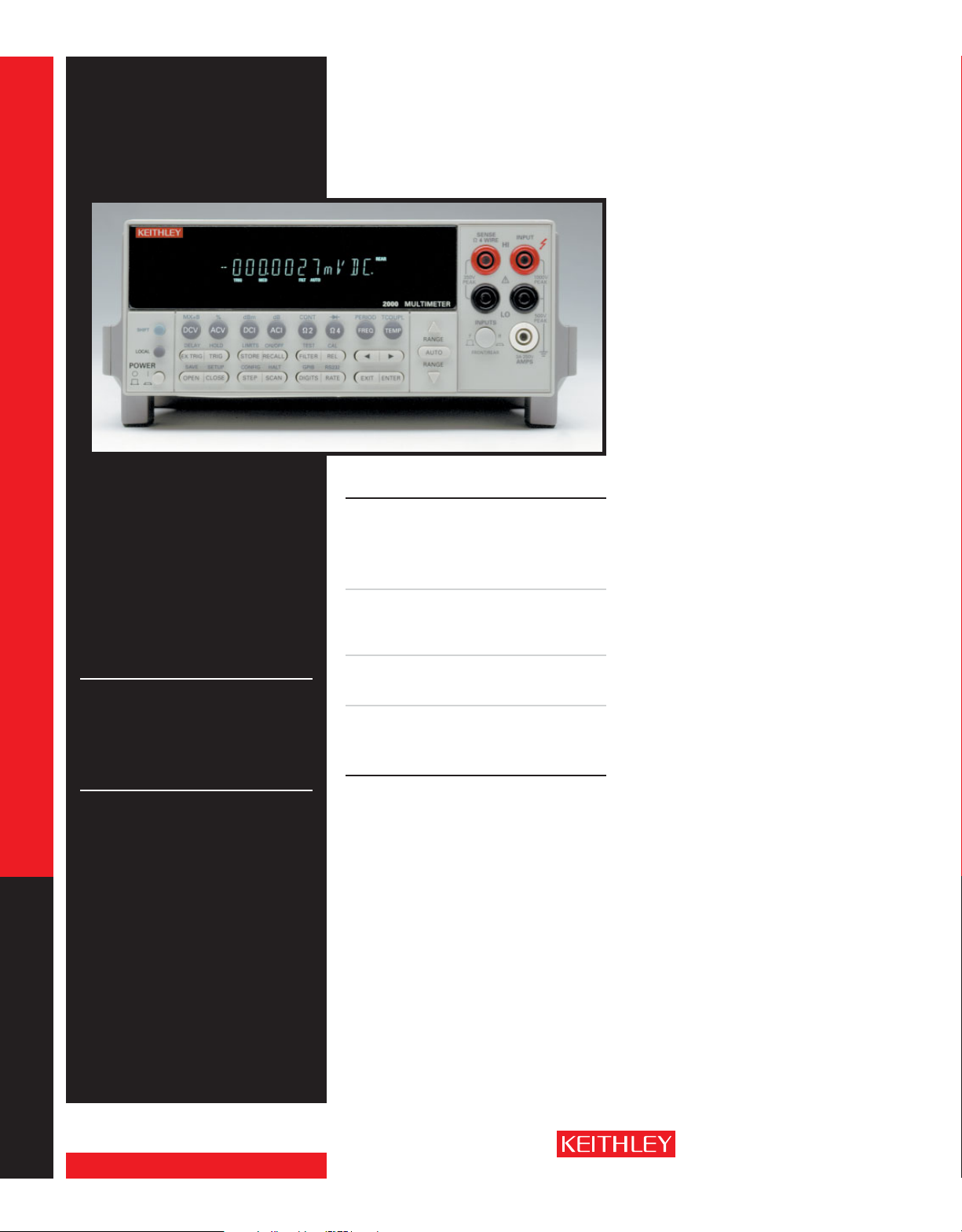
The Model 2000 6½-Digit Multimeter is part of
Keithley’s family of high performance DMMs.
Based on the same high speed, low noise A/D
converter technology as the Model 2001 and
2002, the 2000 is a fast, accurate, and highly
stable instrument that’s as easy to operate as it is
to afford. It combines broad measurement ranges with superior accuracy specifications — DC
voltage from 100nV to 1kV (with 0.002% 90-day
basic accuracy) and DC resistance from 100µ
to 100M
Ω
(with 0.008% 90-day basic accuracy).
Ω
Optional switch cards enable multiplexing up to
20 different input signals for multipoint measurement applications.
High Throughput
The 2000 offers exceptional measurement
speed at any reso lution. At 6½ digits, it delivers
50 triggered rdgs/s over the IEEE-488 bus. At
4½ digits, it can read up to 2000 rdgs/s into its
internal 1024 reading buf fer, making it an excellent choice for applications where throughput is
critical.
For benchtop or stand-alone applications, the
2000 has a front panel design that’s simple
to understand and easy to use. The 2000 has
13 built-in measurement functions, including
DC V, AC V, DCI , ACI, 2WΩ, 4WΩ, temper ature,
frequency, period, dB, dBm, continuity mea surement, and diode testing. A built-in RS-232 interface con nects to a notebook or full-sized PC’s
serial port to take, store, process, and dis play
m e a s u r e m e n t s a u t o m a t i c a l l y .
General-purpose instrument that’s as easy to operate as it is to afford
1.888.KEITHLEY
DIGITAL MULTIMETERS & SYSTEMS
www.keithley.com
(U.S. only)
A GREATER ME ASURE OF C ONFIDENC E
Page 2
2000
6½-Digit Multimeter
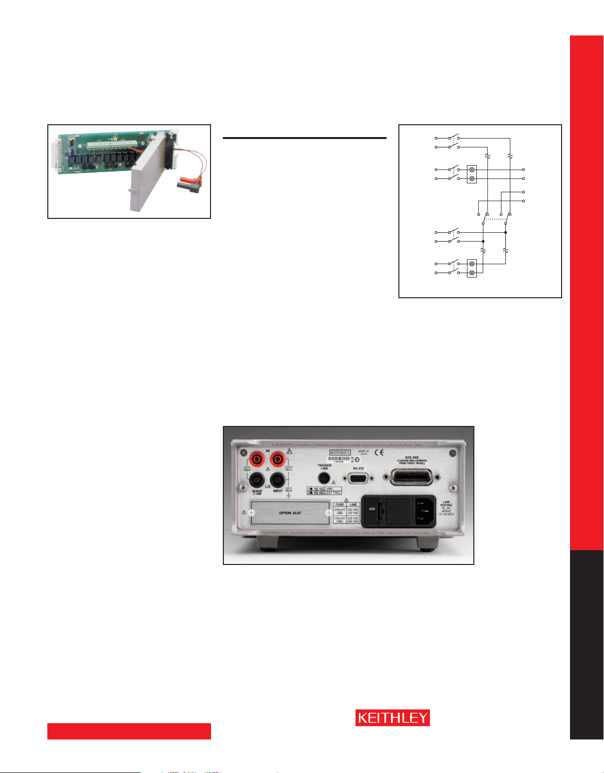
Optional Multiplexer Cards
Creating a self-contained multipoint measurement solution is as simple as plugging a scanner
card into the option slot on the 2000’s back
panel. This ap proach eliminates the complexities
of triggering, timing, and processing issues and
helps reduce test time significantly. For applications involving more than 10 measurement
points, the 2000 is com patible with Keithley’s
Series 7000 switch matrices and cards.
Model 2000-SCAN Scanner Card
• Ten analog input channels (2-pole)
• Configurable as 4-pole, 5-channel
Model 2001-SCAN Scanner Card
• Ten analog input channels
• Two channels of 2-pole, high-speed, solidstate switching
General-purpose instrument that’s as easy to operate as it is to afford
Model 2001-TCSCAN
Thermocouple Scanner Card
• Nine analog input channels
• Built-in temperature reference for thermocouple cold-junction compensation
SCANNER OPTION 2000-SCAN
GENER AL: 10 channels of 2-pole relay input. All channels con-
figurable to 4-pole.
CAPABILITIES: Multiplex one of ten 2-pole or one of five 4-pole
signals into DMM.
INPUTS
Maximum Signal Level:
DC Signals: 110V DC, 1A switched, 30VA maximum (resis-
tive load).
AC Signa ls: 125V AC rms or 175V AC peak, 100kHz maxi-
mum, 1A switched, 62.5VA maximum (resistive load).
Contact Li fe: >10
operations cold switch ing.
Contact Resistance: <1Ω at end of contact life.
Actuation Time: 2.5ms maximum on/off.
Contact Potential: <±500nV typical per contact, 1µV max.
<±500nV typical per contact pair, 1µV max.
Connector Type: Screw terminal, #22 AWG wire size.
Isolation Between A ny Two Terminals: >10
Isolation Between A ny Terminal and Earth: >1 09Ω, <150pF.
Common Mode Voltage: 350V peak between any terminal
and earth.
Maximum Voltage Bet ween Any Two Terminals: 200V
peak.
Maximum Voltage Bet ween Any Termina l and Model
2001 Input LO: 200V peak.
ENVIRONMENTAL: Meets all Model 2000 environmental
specifications.
DIMENSIONS, WEIGHT: 21mm high × 72mm wide × 221mm
deep (0.83 in. × 2.83 in. × 8.7 in.). Adds 0.4kg (10 oz.).
5
operations at maximum signal level; >108
9
Ω
, <75pF.
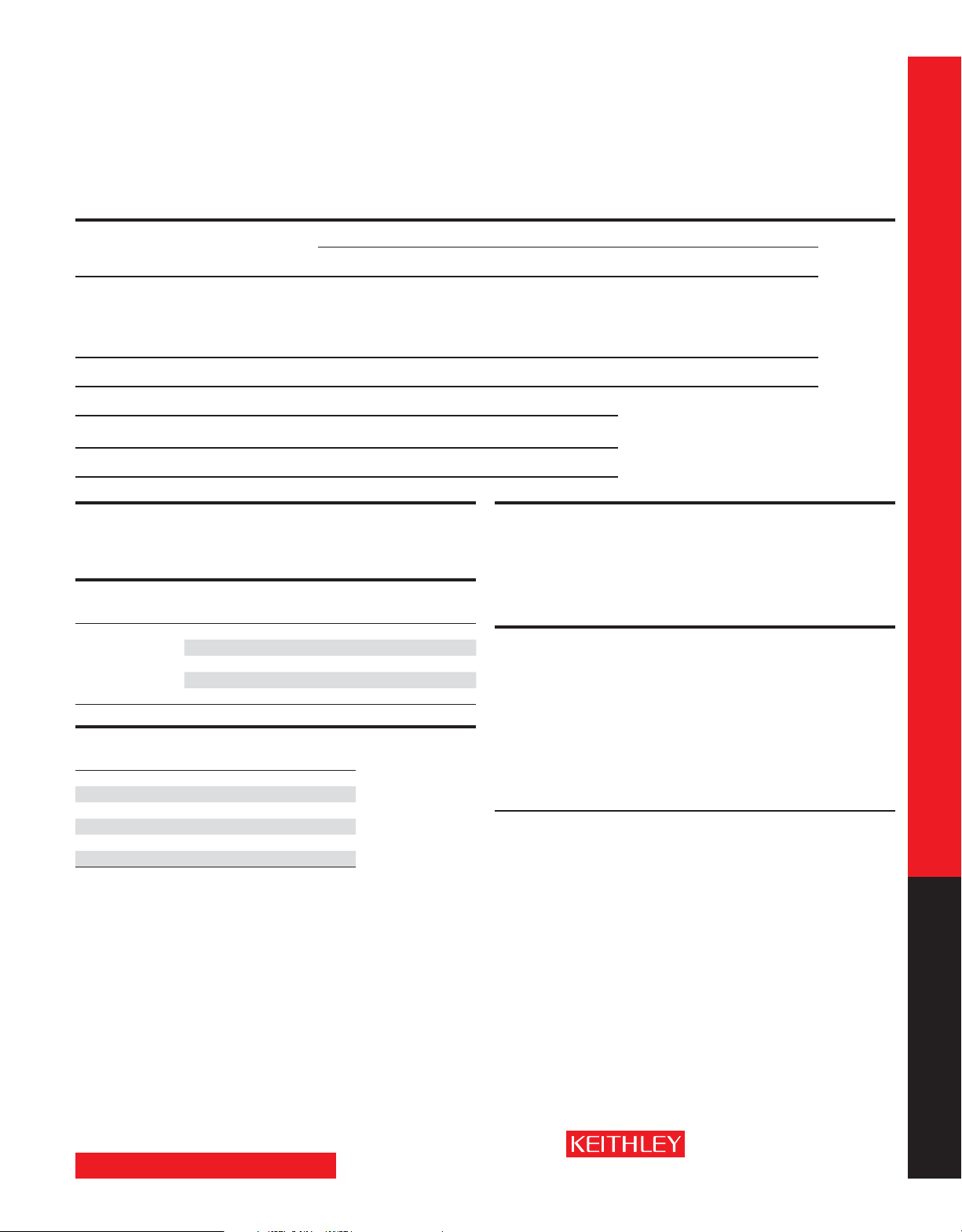
HI
Ch. 1
LO
Ch. 2–4
HI
Ch. 5
LO
HI
Ch. 6
LO
Ch. 7–9
HI
Ch. 10
LO
* Solid-state relays in the 2001-SCAN only.
*
4-pole 2-pole
*
HI
Out A
LO
HI
Out B
LO
Scanner Configuration for Models 2000-SCAN
and 2001-SCAN
General-purpose instrument that’s as easy to operate as it is to afford
1.888.KEITHLEY
www.keithley.com
(U.S. only)
A GREATER ME ASURE OF C ONFIDENC E
DIGITAL MULTIMETERS & SYSTEMS
Page 3

2000
DC Characteristics
6½-Digit Multimeter
Conditions: MED (1 PLC)1 or SLOW (10 PLC)
or MED (1 PLC) with filter of 10
Test Current
Function Range Resolution
Voltage
100.0000 mV 0.1 µV
1.000000 V 1.0 µV
10.00000 V 10 µV
Resistance
Current
100.0000 V 100 µV
1000.000 V
15
100.0000
1.000000
10.00000
100.0000
1.000000
10.00000
100.0000
10.00000 mA 10 nA < 0.15 V 60 + 30 300 + 80 500 + 80 50 + 5
kΩ
kΩ
kΩ
MΩ
MΩ
MΩ
9
Ω
1 mV
100
1
10
16
11, 16
11, 16
100
1
10
100
or Burden Voltage
µΩ
mΩ
mΩ
mΩ
Ω
Ω
Ω
(±5%)
Resistance
> 10 GΩ
> 10 GΩ
> 10 GΩ
10 MΩ ±1%
10 MΩ ±1%
1 mA 30 + 30 80 + 40 100 + 40 8 + 6
1 mA 20 + 6 80 + 10 100 + 10 8 + 1
100 µA 20 + 6 80 + 10 100 + 10 8 + 1
10 µA 20 + 6 80 + 10 100 + 10 8 + 1
10 µA 20 + 6 80 + 10 100 + 10 8 + 1
700
nA // 10MΩ
700
nA // 10MΩ
100.0000 mA 100 nA < 0.03 V 100 + 300 300 + 800 500 + 800 50 + 50
1.000000 A 1 µA < 0.3 V 200 + 30 500 + 80 800 + 80 50 + 5
3.00000 A 10 µA < 1 V 1000 + 15 1200 + 40 1200 + 40 50 + 5
Continuity 2W
Model 2000 specifications
Diode Test
1
kΩ
3.00000 V 10 µV 1 mA 20 + 6 30 + 7 40 + 7 8 + 1
100
mΩ
1 mA 40 + 100 100 + 100 120 + 100 8 + 1
10.00000 V 10 µV 100 µA 20 + 6 30 + 7 40 + 7 8 + 1
10.00000 V 10 µV 10 µA 20 + 6 30 + 7 40 + 7 8 + 1
DC OPERATING CHARACTERISTICS
Function Digits Readings/s PLCs
DCV (all ranges), 6½
DCI (all ranges), and 6½
Ohms (<10M range) 6½
DC SYSTEM SPEEDS
2, 6
2
3, 4
3, 7
3, 5
3, 5
5½
5
5½
5
5½
5
4½
510
30 1
50 1
270 0.1
500 0.1
1000 0.04
2000 0.01
RANGE CHANGE 3: 50/s.
3
FUNCTION CHANGE
AUTORANGE TIME
3, 10
: 45/s.
: <30ms.
ASCII READINGS TO RS-232 (19.2K BAUD): 55/s.
MAX. INTERNAL TRIGGER RATE: 2000/s.
MAX. EXTERNAL TRIGGER RATE: 400/s.
DC GENERAL
LINEARITY OF 10VDC RANGE: ±(1ppm of reading + 2ppm of range).
DCV, Ω, TEMPERATURE, CONTINUITY, DIODE TEST INPUT PROTECTION: 1000V, all ranges.
MAXIMUM 4WΩ LEAD RESISTANCE: 10% of range per lead for 100Ω and 1kΩ ranges; 1kΩ per
lead for all other ranges.
DC CURR ENT INPUT PROTECTION: 3A, 250V fuse.
SHUNT RESISTOR: 0.1Ω for 3A, 1A, and 100mA ranges. 10Ω for 10mA range.
CONTINUITY THRESHOLD: Adjustable 1Ω to 1000Ω.
AUTOZERO OFF ERROR: Add ±(2ppm of range error + 5µV) for <10 minutes and ±1°C change.
OVER RANGE: 120% of range except on 1000V, 3A, and diode.
Input
Accuracy: ±(ppm of reading + ppm of range)
(ppm = parts per million)
(e.g., 10ppm = 0.001%)
14
24 Hour
23°C ± 1°
90 Day
23°C ± 5°
1 Year
23°C ± 5°
Temperature
Coefficient
0°–18°C and 28°–50°C
30 + 30 40 + 35 50 + 35 2 + 6
15 + 6 25 + 7 30 + 7 2 + 1
15 + 4 20 + 5 30 + 5 2 + 1
15 + 6 30 + 6 45 + 6 5 + 1
20 + 6 35 + 6 45 + 6 5 + 1
150 + 6 200 + 10 400 + 10 95 + 1
800 + 30 1500 + 30 1500 + 30 900 + 1
SPEED AND NOISE REJECTION
8
Rate Readings/s Digits
10 PLC 5 6½ < 1.5 µV 60 dB 140 dB
1 PLC 50 6½ < 4 µV 60 dB 140 dB
0.1 PLC 500 5½ < 22 µV — 80 dB
0.01 PLC 2000 4½ < 150 µV — 80 dB
DC NOTES
1. Add the following to “ppm of range” uncertai nty:1V and 100V, 2ppm; 100mV, 15ppm; 100Ω, 15ppm; 1kΩ –
<1MΩ, 2ppm; 10mA and 1 A, 10ppm; 100mA, 4 0ppm.
2. Speeds are for 60H z operation using factory def ault operating conditions (*RST). Autorange off, Display of f,
Trigger delay = 0.
3. Speeds include measurement and binary d ata tran sfer out the GPIB.
4. Auto zero off.
5. Sample count = 1024, auto zero off.
6. Auto zero off, NPLC = 0.01.
7. Oh ms = 24 r ead ing s/s econd.
8. 1 PLC = 16.67ms @ 60Hz, 20ms @ 50H z/400Hz. The frequency is automatically determined at power up.
9. For signal levels >50 0V, add 0.02ppm/ V uncertaint y for the portion exceeding 500V.
10. Add 120ms for ohms.
11. Must have 10% matching of lead resistance in Input HI and LO.
12. For line frequenc y ±0.1%.
13. For 1kΩ unbalance in LO lead.
14. Relative to calibration accuracy.
15. Specifications are for 4 -wire ohm s. For 2-wire ohms, add 1Ω additional uncertainty.
16. For rear inputs, add the following to temper ature coefficient “ppm of reading” uncertainty 10MΩ 95ppm,
100M Ω 900ppm. Operating envi ronment spe cified for 0º to 50ºC and 50% RH at 35ºC.
RMS Noise 10V
Range NMRR
Model 2000 specifications
12
CMRR
13
1.888.KEITHLEY
DIGITAL MULTIMETERS & SYSTEMS
www.keithley.com
(U.S. only)
A GREATER ME ASURE OF C ONFIDENC E
Page 4
2000
6½-Digit Multimeter
True RMS AC Voltage and Current Characteristics
Accuracy 1: ±(% of reading + % of range), 23°C ± 5 °C
Voltage
Range Resolution Calibration Cycle 3 Hz–10 Hz
100.0000 mV 0.1 µV
1.000000 V 1.0 µV 90 Days 0.35 + 0.03 0.05 + 0.03 0.11 + 0.05 0.60 + 0.08 4 + 0.5
10.00000 V 10 µV
100.0000 V 100 µV 1 Year 0.35 + 0.03 0.06 + 0.03 0.12 + 0.05 0.60 + 0.08 4 + 0.5
750.000 V 1 mV
Temperature
Coefficient/°C
Current
Range Resolution Calibration Cycle 3 Hz–10 Hz 10 Hz–3 kHz 3 kHz–5 kHz
1.000000 A 1 µA 90 Day/1 Year 0.30 + 0.04 0.10 + 0.04 0.14 + 0.04
9
3.00000 A
10 µA 90 Day/1 Year 0.35 + 0.06 0.15 + 0.06 0.18 + 0.06
Temperature
Coefficient/°C
0.035 + 0.003 0.005 + 0.003 0.006 + 0.0 05 0.01 + 0.006 0.03 + 0.01
8
0.035 + 0.006 0.015 + 0.006 0.015 + 0.006
8
10
10 Hz–20 kHz 20 kHz–50 kHz 50 kHz–100 kHz 100 kHz–300 kHz
HIGH CREST FACTOR ADDITIONAL ERROR ±(% of reading)
CREST FACTOR: 1–2 2–3 3–4 4–5
ADDITIONAL ERROR: 0.05 0.15 0.30 0.40
Model 2000 specifications
AC OPERATING CHARACTERISTICS
Function Digits Readings/s Rate Bandwidth
ACV (all ranges), and 6½
ACI (all ranges) 6½
3
3
4
6½
3
6½
4
6½
2
2s/reading SLOW 3 Hz–300 kHz
1.4 MED 30 Hz–30 0 kHz
4.8 MED 30 Hz–300 kHz
2.2 FAST 300 Hz–300 kHz
35 FAST 300 Hz–300 kHz
ADDITIONAL LOW FREQUENCY ERRORS ±(% of reading)
Slow Med Fast
20 Hz – 30 Hz 0 0.3 —
30 Hz – 50 Hz 0 0 —
50 Hz – 100 Hz 0 0 1.0
100 Hz – 200 Hz 0 0 0.18
200 Hz – 300 Hz 0 0 0.10
> 300 Hz 0 0 0
7
AC SYSTEM SPEEDS
FUNCTION/RANGE CHANGE 6: 4/s.
AUTORANGE TIME: <3s.
ASCII READINGS TO RS-232 (19.2K BAUD)
MAX. INTERNAL TRIGGER RATE
MAX. EXTERNAL TRIGGER RATE
2, 5
4
: 300/s.
4
: 300/s.
4
: 50/s.
Model 2000 specifications
AC GENERAL
INPUT IMPEDANCE: 1MΩ ±2% paralleled by <100pF.
ACV INPUT PROTECTION: 1000Vp.
MAXIMUM DCV: 400V on any ACV range.
ACI INPUT PROT ECTION: 3A, 250V fuse.
BURDEN VOLTAGE: 1A Range: <0.3V rms. 3A Range: <1V rms.
SHUNT RESISTOR: 0.1Ω on all ACI ranges.
AC CMRR: >70 dB wi th 1 kΩ in LO lead.
MAXIMUM CREST FACTOR: 5 at full scale.
VOLT HERTZ PRODUCT: ≤8 × 10
OVER RANGE: 120% of range except on 750V and 3A ranges.
AC NOTES
1. Specifications are for SLOW rate and sinewave inputs >5% of range.
2. Speeds are for 6 0Hz operation using factor y default operating conditions (*RST). Auto zero off, Auto ra nge off,
Display of f, includes measurement and binary data transfer out the GPIB.
3. 0.01% of step settling error. Trigger delay = 400ms.
4. Trigger delay = 0.
5. DETector:BANDwidth 300, NPLC = 0.01.
6. Maximum useful limit with t rigger delay = 175ms.
7. Applies to non-sinewaves >5Hz and <500Hz (gua ranteed by design for crest factors >4.3).
8. Applies to 0°–18°C and 28°–50°C.
9. For signal levels >2,2A, add additional 0.4% to “of reading” uncertainty.
10. Typical uncertainties. Typical represent s two sigma or 95% of manufactured units measu re <0.35% of reading
and three sigma or 99.7% measure <1.06% of readi ng.
7
V·Hz.
1.888.KEITHLEY
www.keithley.com
(U.S. only)
A GREATER ME ASURE OF C ONFIDENC E
DIGITAL MULTIMETERS & SYSTEMS
Page 5

2000
6½-Digit Multimeter
Triggering and Memory
REA DING HOLD SENSITIVITY: 0.01%, 0.1%, 1%, or 10% of reading.
TRIGGER DELAY: 0 to 99 hrs (1ms step size).
EXTERNAL TRIGGER LATENCY: 200µs + <300µs jitter with autozero off, trigger delay = 0.
MEMORY: 1024 reading s.
Math Functions
Rel, Min/Max /Average/StdDev (of stored reading), dB, dBm, Limit Test, %, and mX+b with user
defined units displayed.
DBM REFERENCE RESISTANCES: 1 to 9999Ω in 1Ω increments.
Standard Programming Languages
SCPI (Standard Commands for Programmable Instruments)
Keith ley 196/199
Fluke 8840A, Fluke 8842A
Remote Interface
GPIB (IEEE-488.1, IEEE-488.2) and RS-232C.
Model 2000 specifications
±(ppm of
reading)
1, 2
Accuracy
90 Day/1 Year
±(% of reading)
Frequency and Period Characteristics
ACV
Frequency
Range
100 mV
to 750 V
FREQUENCY NOTES
1. Specifications are for square wave inputs only. Input signal must be >10% of ACV range. If input is <20mV on
the 100mV range, then frequency must be >10Hz.
2. 20% overrange on all ranges except 750V range.
Range
3 Hz to
500 kHz
Period
Range Gate Time
333 ms to
1 s (SLOW) 0.3 0.01
2 µs
Resolution
Temperature Characteristics
Thermocouple
Type Range Resolution
J –200 to + 760°C 0.001°C ±0.5°C ±0.65°C
K –200 to + 1372°C 0.001°C ±0.5°C ±0.70°C
T –200 to + 400°C 0.001°C ±0.5°C ±0.68°C
TEMPERATURE NOTES
1. For temperatures <–100°C, add ±0.1°C and >900°C add ±0.3°C.
2. Temperature can be displayed in °C, K or °F.
3. Accurac y based on ITS-90.
4. Exclusive of thermocouple error.
5. Specifications apply to channels 2–6. Add 0.06°C/channel from channel 6.
2, 3, 4
90 Day/1 Year (23°C ± 5°C )
Relative to
Reference Junction
GENERAL
POWER SUPPLY: 100V / 120V / 220V / 240V.
LINE FREQUENCY: 50Hz to 60Hz and 400Hz, automatically sensed at power-up.
POWER CONSUMPTION: 22VA.
VOLT HERTZ PRODUCT: ≤8 × 10
OPERATING ENVIRONMENT: Specified for 0°C to 50°C. Specif ied to 80% R.H. at 35°C
and at an altitude of up to 2000m.
STORAGE ENVIRONMENT: –40°C to 70°C.
SAFET Y: Conforms to European Union Low Voltage Directive.
EMC: Conforms to European Union EMC Directive.
WAR MUP: 1 hour to rated accuracy.
VIBRATION: MIL-PRF-2800F Class 3 Random.
DIMENSIONS:
Rack Mounting: 89mm high × 213mm wide × 370mm deep (3.5 in × 8.38 in × 14.56 in).
Bench Configuration (with handle and feet): 104mm high × 238mm wide × 370mm
deep (4.13 in × 9.38 i n × 14.56 i n).
NET WEIGHT: 2.9kg (6.3 lbs).
SHIPPING WEIGHT: 5kg (11 lbs).
7
V·Hz .
Accuracy
1
2001-TCSCAN
Using
5
Model 2000 specifications
1.888.KEITHLEY
DIGITAL MULTIMETERS & SYSTEMS
www.keithley.com
(U.S. only)
A GREATER ME ASURE OF C ONFIDENC E
 Loading...