

Page 1

INSTRUCTION MANUAL
MODELS 200,200A
ELECTROMETER VOLTMETERS
Page 2
WARRANTY
We warrant each of our products to be free
from defects in material and workmanship. Our
obligation under this warranty is to repair or
replace any instrument or part thereof (except
tubes and batteries) which, within a year after
shipment, proves defective upon examination.
We will pay domestic surface freight costs.
To exercise this warranty, call your local field
representative or the plant directly, DDD 216.
795.2666. You will be given assistance and
shipping instructions.
REPAIRS AND RECALIBRATION
Keithley Instruments maintains a complete re-
pair service and standards laboratory in Cleve-
land, and has authorized field repair facilities
in Los Angeles and Albuquerque.
To insure prompt repair or recalibration serv.
ice, please contact your local field representative, or the plant directly, before returning
the instrument.
Estimates for repairs, normal recalibrations,
and calibrations traceable to the National Bu-
reau of Standards are available upon request.
Page 3
MODEL 200, 2OOAELFLYl'ROMEXl'ER
TARLE OF COl4TEN'B
Title
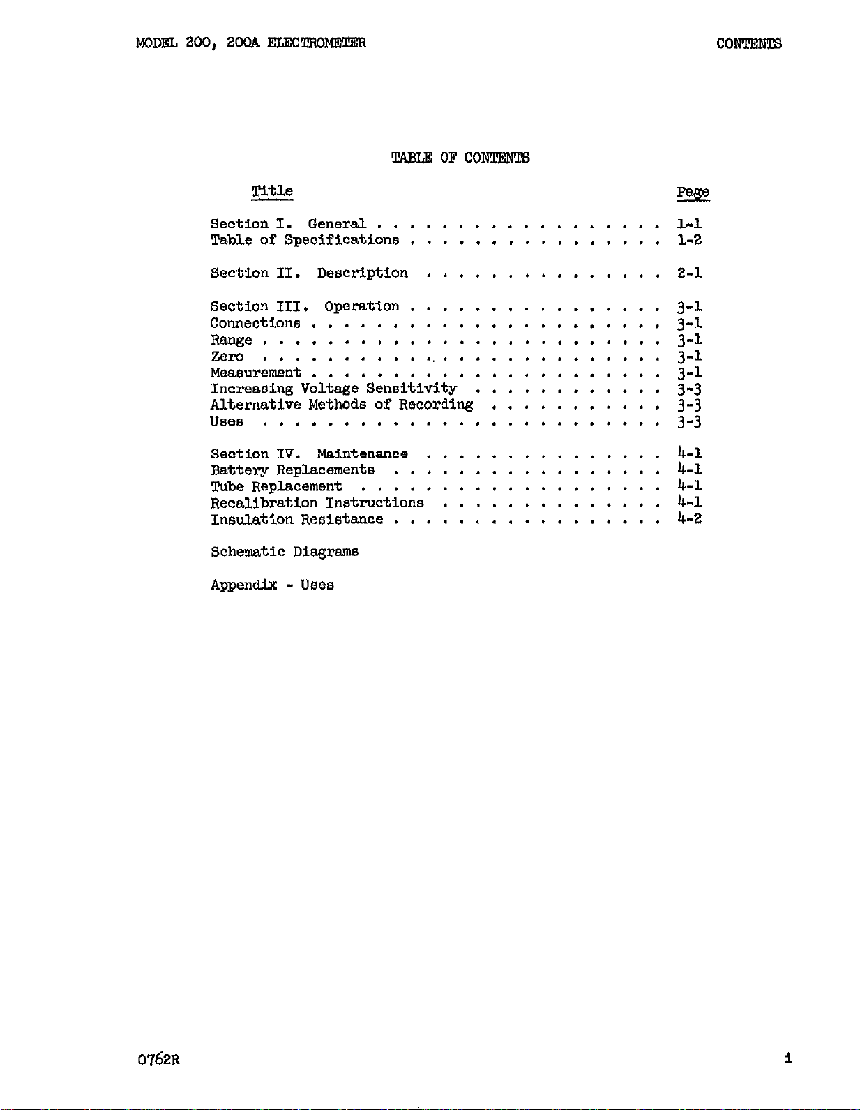
Section I. General .................. L-1
Table of Specificationa ................ l-2
section II. Description ............... 2-l
Section III. Operation ................
EeE!
3-l
Connections ...................... 3-1
Range ......................... 3-l
Zero
Measurement ......................
Increasing Voltage Sensitivity ............
Alternative Methods of Recording ...........
..........................
3-l
3-1
3-3
3-3
Uses ......................... 3-3
Section IV.
Battery Replacements .................
Tube Replacement ................... 4-l
Recalibration Instructions
Insulation Resistance .................
Schematic Diagrams
Appendix - Uses
Maintenance ...............
..............
4-l
4-l
4-l
4-2
0762~
Page 4
MODEL 200, 200A EI.,EX!TRoMETER
GENERAL
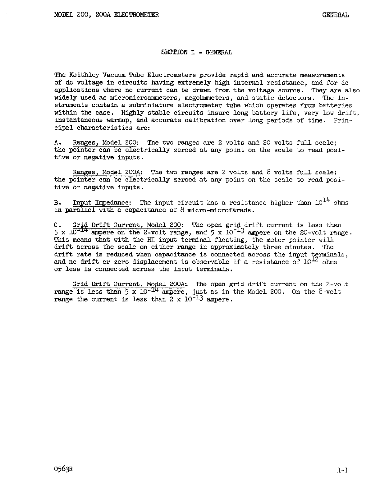
SECTION1 -GENERAL
The Keithley Vacuum Tube Electrometers provide rapid and accurate measurements
of dc voltage in circuits having extremely high internal resistance, and for dc
applications where no current can be drawn from the voltage source.
They are also
widely used as micromicroammeters, megohmmeters, and static detectors. The in-
struments contain a subminiature electrometer tube which operates from batteries
within the case.
Highly stable circuits insure long battery life, very low drift,
instantaneous warmup, and accurate calibration over long periods of time. Principal characteristics are:
A. Ranges, Model 200:
The two ranges are 2 volts and 20 volts full scale;
the pointer can be electrically zeroed at any point on the scale to read positive or negative inputs.
Ranges, Model 2oOA: The two ranges are 2 volts and 8 volts full scale;
the pointer can be electrically zeroed at any point on the scale to read positive or negative inputs.
B. Input Impedance: The input circuit has a resistance higher than 1014 ohms
in parallel with a capacitance of 8 micro-microfarads.
C. Grid Drift Current, Model 200: The open grid drift current is less than
5
x 10eL* ampere on the 2-volt range, and 5 x 10-l-3 ampere on the 20-volt range.
This means that with the RI input terminal floating, the meter pointer
will
drift across the scale on either range in approximately three minutes. The
drift rate is reduced when capacitance is connected across the input
and no drift or zero displacement is observable if a resistance of
10
or less is connected across the input terminals.
Grid Drift Current, Model ZOOA:
range is less than 5 x 10-l" ampere, just as in the Model 200. On the
The open grid drift current on the 2..volt
8-volt
range the current is less than 2 x lo-13 ampere.
05633
l-l
Page 5
MODEL 200, 200A ELECTROMETER
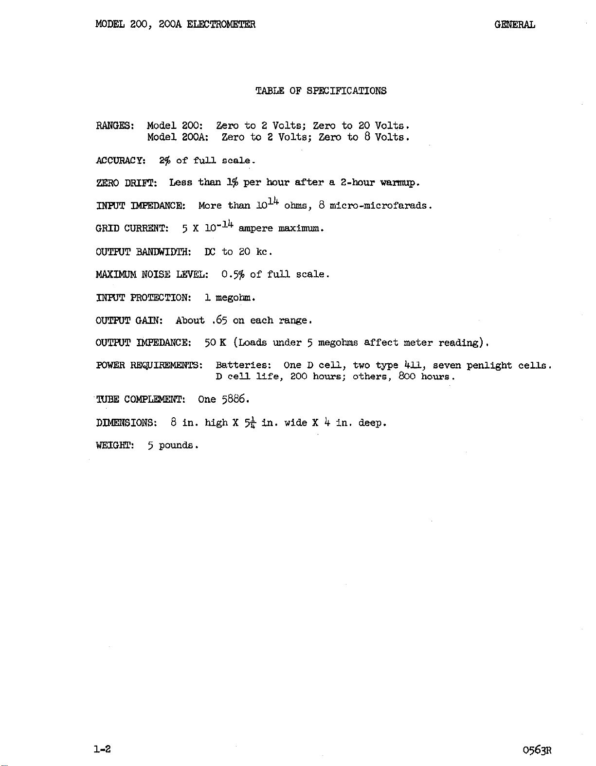
TABLE OF SPEKIFICATIONS
RANGES: Model 200:
Zero to 2 Volts; Zero to 20 Volts.
Model 2OCA: zero to 2 Volts; Zero to 8 Volts.
AccuRAcy:
ZERO DRIFT:
INPUT IMPEDANCB:
GRID CURRENT: 5 X lo-l4
2% of full scale.
Less than 1% per hour after a 2-hour warmup.
More than 1014
ampere maximum.
OUTPUT RANDWIDTH: DC to 20 kc.
MAXIMCM NOISE LZVRL:
0.5%
of full scale.
INPUT PROTECTION: 1 megohm.
OUTFUTGAIN:
About
OUTHJT IMPEDANCE:
.65
on each range.
50K
(Loads under 5 megohms affect meter reading).
POWER REQUIREMENTS: Batteries:
D cell life, 200 hours; others, 800 hours.
"IWE COMPLEMENT: one
5886.
ohms, 8 micro-microfarads.
One D cell, two type 4l.l, seven penlight cells.
DIMENSIONS:
WZIGRT:
8 in. high X
5
pounds.
5*
in. wide X 4 in. deep.
1-2
0563~
Page 6
MODEL 200, 200A ELEXXROMEX!FB
DFixxtpmON
SECTION II - DESCRII'TION
The equipment layout and circuit schematic diagrams are enclosed at the back of
the bulletin.
A.
Meter:
The large meter on the face of the instrument indicates the dc poten-
tial inlts across the input terminals.
B. Selector switch, Model 200 (OFF-20-2):
The right hand knob on the panel turns
the instrument off or to the 20-or 2-volt r-es.
Selector switch, Model 2OOA (OFF-8-2):
The right hsnd knob on the panel turns
the instrument off or to the &or a-volt ranges.
C. zero:
The knob at the left is the electrical zero adjustment; with it, the
meterpointer can be set to any point on the scale with the input terminals connected together.
The scale is marked for zero at the left and for zero at the
center.
D. Input Terminals:
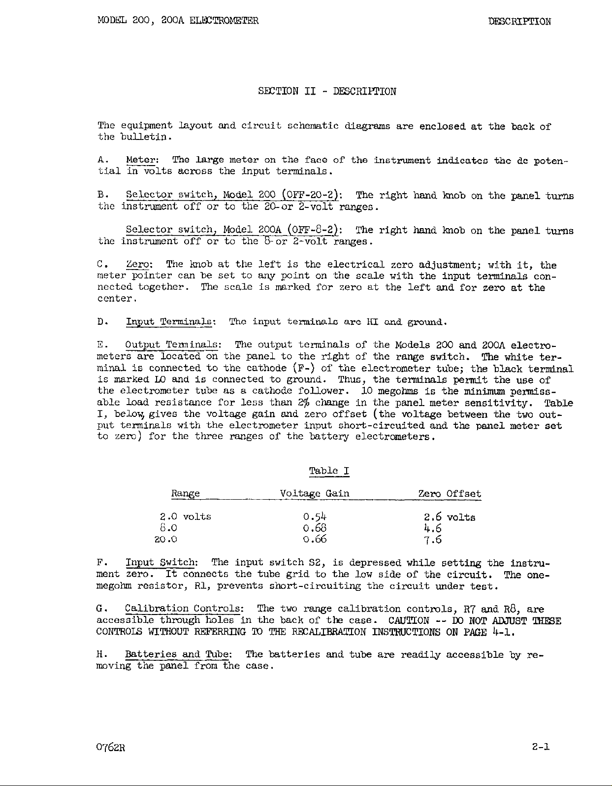
E.
Output Terminals:
meters
are located on the panel to the right of the range switch. The white ter-
The input terminals are RI and ground.
The output terminals of the Models 200 and 2OOA electro-
minal is connected to the cathode (F-) of the electrometer tube; the black terminal
is marked I.0 and is connected to ground. Thus, the terminals permit the use of
the electrometer tube as a cathode follower. 10 megohms is the minimwn permissable load resistance for less than 2% change in the panel meter sensitivity. Table
I, below, gives the voltage gain and zero offset (the voltage between the two out-
put terminals with the electrometer input short-circuited and the panel meter set
to zero) for the three ranges
of the battery electrometers.
Table I
Range
Voltage Gain Zero Offset
0.54 2.6 volts
i:: vo1ts
20.0
0.68
0.66
4.6
7.6
F. Input Switch: The input switch 52, is depressed while setting the instrument zero.
It connects the tube grid to the low side of the circuit. The one-
megohm resistor, Rl, prevents short-circuiting the circuit under test.
G.
Calibration Controls:
accessible through holes in the back of the case.
The two range calibration controls, R7 and R8, are
CAUTTON -- W NOT AJNUST THFSE
CONTROLS hITROUT -G 'x) THE RFCALIBRATION INSTRUCTIONS ON PAGE 4-l.
H. Batteries and Tube: The batteries and tube are readily accessible by re-
moving the panel from the case.
0762R
2-l
Page 7
MODEL 200, 2OOA EL?3CTROIWl'EX
SECTION III - OPERATION
The Model 200 and Model 2OOA VIXUUII Tube Electrometers arc shipped complete with
a fresh set of batteries, and are accurately calibrated at the factory.
applications and circuit possibilities for use of these instruments are discussed
in the appendix.
Connections:
A.
or hi-insulated terminal, of the circuit under test.
input terminal.
Range, Model 200:
B.
as required to read the voltage across the input terminals.
ials ,over 20 volts, the ground terminal can be raised in potential to approximate
the source voltage and the difference rea on the Electrometer, as discussed on
paQ;e U.
1OC:l and 1OOO:l Voltage Divi.ders,'Models 2006 and 2007 respectiveq may be used
to extend the'maxiium voltage to 20,000 volts.
Or, if a shunt resistance of 10
The HI terminal should be connected to the high resistance,
Ground is the other
Set the range switch at the Z-volt or 20-volt position
In measuring potent-
$2
ohms across the source is permissible,
OPEmON
NWIIWOUS
Range,Model ZOOA: Set the range switch at the 2-volt or O-volt position as
required to read the voltage across the input terminals.
over 8 volts the methods discussed on page IA nay be used, or, if a 10
is permissible, 1OO:l and 1OOO:l Voltage Dividers, Models
may be used to extend the maximum voltage to 8000 volts.
Be certain that the range switch is in the OFP position after using the instrument
to avoid unnecessary discharge of the batteries.
C. zero:
rotatzthe ZERO lmob to bring the meter pointer to the desired zero. If the
voltage to be measured is positive, use the zero point at the left of the scale
to take advantage of the full scale range;
negative, use the mid-scale zero; or zero at the right for large negative potent-
ials. Depressing the input switch connects a one-megohm resistance across the
input terminals. If charged capacitors are in the circuit under test, they will
be discharged or brought to the proper initial state of charge, as the case may
be,when the input switch is closed.
vents high surge currents from flowing.
Measurement:
D.
in mind the full-scale voltage corresponding to the position of the range switch
At this point, several precautions should be mentioned.
1.
usually be shielded adequately against stray electrostatic and power frequency
fields by keeping the HI lead short - no more than a few inches long.
The instrument should be zeroed b;r depre oning the input switch and
if the voltage changes sign or is
In any case, the one-megohm resistor pre-
Read the voltage directly on the appropriate scale, keeping
Shielding;:. Circuits with internal resistance less than lOlo ohms can
In measuring~otentials
ohm load
2006
and 2007 respectively,
It is sometimes necessary to enclose the highly insulated portion of the cir-
cuit and lead to the HI terminal in an electrostatic shield. Support insulators may be fashioned from polystyrene or polyethylene stock. The impor-
tance of rigid supports cannot be overemphasized, especially if the shield
is at a high potential with respect to the HI terminal. Small relative motions
0762~ 3-l
Page 8

OPEWION
of these parts cause .the capacitance ofthe system to change, and as the charge
remains constant, large changes in potentials result from the motion, as in
the fsmiliar condenser microphone.
the HI leads moving over the surface of an insulating support can also cause
annoying disturbances.
2.
to approach one second when the
the Electrometer gets above 1011
6
stops moving.
so that any drift that is apparent can usually be attributed to drift in
the circuit under test or to slow recovery in circu.its having extremely
long time constants.
The most significant exception is that upscale drift will occur if there
is no resistor across the input terminals of the Electrometer and the capacitance between these terminals is low or virtually only the internal capacity of the instrument.
the circuit'being measured and the pointer drifts slowly upscale.
MODEL 200, 200A ?&ECTROMETXR
Frictions.1 electricity which results from
Time Constant:
The RC time constant of the measurement circuit begins
resistance across the input terminals of
ohms, for the input capacitance is about
mmf. To get accurate readings, it is necessary to wait until the pointer
The inherent circuit drift of the Electrometer is very low,
Here, the reverse grid current of the tube charges
Correction for Grid Current: The grid current of the Electrometer
3.
may be measured by timing the open-grid drift upscale.
I = C$ = 6 x l~-~~-$-smpere
In making this ,test the HI terminal should be shielded, preferably by a
metal tube large enough to slip over the guard ring. The following table
illustrates the grid current computations for the different ranges:
RANGE
2 volt
8 volt
20 volt
"0
E
t
0 0.2 volt 24 sec. 5.0 X 10"14 ampere
0
0
0.8
2.0
At
24 2.0 x 10⁻¹³
24
5.0 X lo-l3
Alternatively, the g&d current may be measured by observFng the voltage
across a known high resistance connected between the input terminals.
R must be at least 1012 ohms, giving a long time constant, and steady state
conditions must be reached before reading E.
imately constant over the Z-volt range,
but on the 20-volt range, it is
The grid current is approx-
greatest near zero volts and decreases considerably as HI is made more positive .
The grid current may be abnormally high if the tube has not been in use
for a long period. After an hour's operation the grid current should fall
to within the normal limits.
3-2
0762~
Page 9

WDEL 200, 200A EIECTIiCMETER
OPTXWCION
In low current circuits,
the grid current must be subtracted (algebraically)
from the total current read to give the correct current in the circuit being measured.
4.
Correction for Input Capacity:
nal capacitance of the Electrometer shunts any external capacitance
to the input terminals.
The internal capacity is approximately 6 x
It must be remembered that the inter-
co
%cted
10~
farad, and corrections must be made if this is appreciable compared to an
external capacitor whose voltage is being measured.
E. Increasing Voltage Sensitivity: The panel meter on the Models 200 and 200A
has a O-50
in series with the panel
microampere movement.
meter,
the voltage sensitivity of the electrometer, as
If a
more
sensitive galvanometer were connected
read on the galvanometer, would be proportional to the increase in sensitivity
afforded by the galvanometer.
The limitation of the increase in most cases comes
when the zero control of the electrometer becomes too coarse.
F. Alternative Methods of Recordi%: An alternative way to record is to con-
nect a galvsnometer in series with the panel meter, whose movement is O-50 microamperes. Photographic recording is most common with the mirror gal-meters.
The General Electric Photoelectric recorder,
the mirror galvanometer actuates a photoelectric servo
is made to follow the galvanometer deflections.
accessible by removing the cabinet,
then removing the battery tray.
however, has also found use; here,
system,
and a pen recorder
The meter connections are made
G. Uses:
Typical applications of the Electrometer are described in the Appendix.
The s=sted circuits are indicative of the many uses of the instrument in measur-
ing voltage,
current, charge,
capacitance, resistance, and various capacitor par-
ameters more quickly and accurately than was previously possible.
In many cases the circuit arrsngement is greatly simplified through the use of
the various Keithley Electrometer accessories. These include shunts, voltage
dividers, a test voltage supply, and a static detector, listed in the descrip-
tive literature included with the instruction manual.
0762~ 3-3
Page 10

MODEL 200, 2OCAELECTROMETER
SECTION IV - MAINTENANCE
The Keithley Model 200 and Model 200A Vacuum Tube Electrometers have been de-
signed to give long, trouble free service; the only regular attention necessary
is the occasional replacement of batteries.
send hours service in normal use.
the instruments do not require attention throughout the life of the batteries.
The calibration, nevertheless,
after replacing the tube.
The sensitivity adjustments at the rear of
should be rechecked occasionally, and particularly
The tube should give severalthou-
MAINTENANCE
A.
Battery Replacement:
by removing the six No. 4 sheet metal screws around the edge of the panel. Then
remove the battery co;er plate by removing the two screws holding it.
Low batteries may cause the zero to shift beyond the range of the zero control;
they may cause rapid drift, or high forward grid current. Since the D cell (flash-
light cell) has the shortest rated life, it should be checked first; it should
be replaced if it measures below 1.1 volts,
The miniature B batteries should be replaced if they measure less than 12 volts.
If they are too low, the zero control cannot be advanced far enough clockwise
to zero the instrument at full scale on either scale. Low B batteries also cause
high forward grid current on the high end of the 20-volt scale. This is evident
if the zero is set at full scale and the meter drift observed with the input ter-
minals open. The pointer moves quickly downscale, and stops at about
scale. This behaviour indicates that the B batteries should be replaced. Low
penlight cells cause the same effect on the a-volt range. These cells should
be replaced if the series voltage of the 10.5-volt group goes below 7 volts.
Low batteries have very little effect on the calibration of either range, down
to the point where the instrument cannot be zeroed to full scale. When replac-
ing batteries, it is essential that the indicated polarities be observed.
Tube Repticement:
B.
this application, but it can easily be replaced with a Keithley Instruments
Part
~~-5886-3
(Model 200) or
To check the batteries, remove the panel from the case
using a lOOO-ohms-per-volt meter.
3/4 full
The tube should give thousands of hours of service in
w-5886-4
(Model ZOOA) if it becomes damaged.
Observe caution when replacing the tube:
cause leakage from the base of the tube to the grid lead, which impairs the oper-
ation of the instrument in measuring low currents.
in DR 10299 or 10446, Figure
New tubes sometimes exhibit large reverse grid current, which falls to normal
value after an hour's operation.
C. Recalibration Instructions, Model 200:
to read
at these two points on the 2-volt and 20-volt scales gives the best overall ac-
curacy . The 20-volt scale is calibrated by applying
by closing the input switch, and adjusting the pointer to 15 volts with the calibration control at the back of the~instrsment.
fect on the zero setting, so the process should be repeated several times to ob-
tain an accurate setting.
except
1.5
volts end 15 volts to 2% is required for comparison.
1.5
volts are applied to the input terminal.
3.
The s&me procedure is followed with the Z-volt scale,
DIRT or MOISTURE from the RAND2 will
Connect the leads as shown
To reset the sensitivity, a voltmeter
Calibration
15
volts, zeroing the meter
This adjustment has a small ef-
4-l
Page 11

MUNTEWANCE MODEL 200, 200A ELRCTROMETJ?,R
Recalibration Instructions, Model 200A: The procedure is the same as above,
except 6 volts are applied to calibrate the a-volt range.
Adjustments of the calibration control for one range do not affect the other
range in either instrument.
D. Insulation Resistance: Clean insulation is essential for a high input re-
sistance.
grid current by observing the open circuit meter drift (Section 111-D-3).
clean the insulation supporting the RI terminal and supporting the input resistor
inside the case, dust it with a small brush, or if necessary wash it lightly
with carbon tetrachloride.
ation after cleaning, necessitating a wait of several minutes after cleaning
before operation can be resumed.
The insulation resistance will be lowered by extremely high humidity, but the
excellent high resistance properties return when the humidity decreases.
The resistance should always be sufficiently high to permit reading
To
Spurious static charges may accumulate on the insul-
E.
Severe Damage:
procedure outlined above, factory repairs are recommended.
If the instrument cannot be calibrated by following the
4-2
0762~
Page 12

1
:
(R9250K o$*
ZERO AOJ.
R4 275K
E B4 E B4
, .“._
EOUIPYENT
DIAGRAM
RED DO
FIG. 3
TUBE
CONNECTIONS
FIG.1 CIRCUIT SCHEMATIC DIAGRAM
MODEL 200 VACUUM TUBE ELECTROMETER
Page 13

1 DR
10446
-A
CONFIDENTIAL
KEITHLEY INSTRUMENTS
CLEVELAND, OHIO
Page 14

Typical applications are included on the next few pages to indicate the many
measurements which the Electrometer and its accessories can make accurately
end quickly. Full operating instructions for the various accessories are included in the last section of this book.
High resistance source within scale range.
The high resistance or highlyinsulated terminal of the source is connected
to the HI terminal of
directly, as described previously under OPKRATIOK.
the
Electrometer.
The voltane
is read
High resistance source, less than 2
Keithley Models 2006 end 2007 volta
I
o,oclo volts. The
,ge dividers, (1OO:l and.
1OOO:l ratios), convert the Electrometer into an extremely
sensitive kilovoltmeter. 1012 obms input
High resistance source,
buckout method. An additional
voltage source, such as the Keitbley Model
used to
buck out most of the voltage, and the differ-
2004A, is
resistance.
ence is read on the Electrometer. To avoid having excessive grid current flow through the unlau~n voltage
source, the bucking voltage should be made more posi-
tive then the unknown voltage initially, then reduced
until the difference can be reed on the Electrometer. In this appllcatian the G
terminal potential should not be made greater then about
50
volts from ground.
Surfaoe contact potentials in semi-conductors or thermionic
devices.
The vmasurement is made by direct connection to the
Electrometer.
Piezo-electric potentials. The electrode which provides the
best shielding is connected to the G terminal. The other
electrode is connected to the HI terminal. The electrometer
reads the instantaneous voltage at the terminals of the crystal at low frequencies.
The KI lead should be connected so
that it does not move appreciably, particularly with crystals
which have low internal capacitance.
KEITHLEY ?zrw!.x~S
CKWIXAND, OHIO
Page 15

XEITHLEYELECTROMXTERS
Potentials of charged capacitors. Connect HI to the high impedance terminal end G to the low impedance terminal, being
careful not to discharge the capacitor through low resistance
paths while making the connections. The
directly.
Vacuum Tube electrode potentials. The Electrometer is well
suited to measuring electrode potentials in vacuum tube circuits, for only a very slight disturbance is caused by its
connection, even in high resistance circuits.
ticularly desirable in dc amplifier work where small variations in potential can be greatly amplified, upsetting the
normal operating conditions. The HI terminal is connected
to the electrode, and G to ground or an auxiliary potential
source depending on the magnitude of the voltage to be msasured.
potential.
The presence of a large ac signal at the electrode being measured can cause an erroneous reading, because of rectification in the electrometer tube grid circuit,
The peak value of the ac signal should be heldwithin the voltage of the scale
range used,
used.
As shown, a voltage divider is being used to permit measurement of the screen
An alternative method would be the buckout method described above.
or a simple sigaal filter which passes only the dc component can be
This is par-
APPENDIX - USES
Static charge detection. The Electrometer is extremely sen-
sitive to static charges, and can be used to make both qualitative and qusntitive measurements. Addition of the Model 2005
Static Detector accessory, shown here
sitivity of the Electrometer, and confines the sensitivity to a
small cone along the axis of the detector, permitting quick
location of charged objects.
Equipotential contour plotting in an electrolytic aaslogy
tank.
for electrolytic field plotting. Conventional techniques
are ,employed, dc potential is applied, and a high resistance
electrolyte is used.
preset equipotential lines,
be read directly.
The Electrometer is a particularly useful instrument
In addition to the usual following of
the potential of any point can
, permits varying the sen-
KEITHLEY INSTRCMENTS 2A
cLEvEm, OHIO
Page 16

KEITHL?XY ELFCTSOMETEPS
TfFIcALcuRRKNT MFJASDREMENTs
APPEWDIX - USES
The Electrometer is converted quickly to a micromicroammeter by use of the
Decade Shunt, Model 2008, which permits accurate measurements
ampere.
Photoelectric cell current.
ances, small currents which represent very low levels of
illumination can be measured.
leakage across the photocell and its connector low, for the
measured current should be predominantly emission current.
The G terminal should always be kept at ground potential.
Mass spectrometer currents and inverse currents in semi-
conductors can easily be measured by the ssme direct method.
With very high shunt resist-
It is important to keep the
Ion Chamber currenq by accumulaticm of charge, or meas-
llated charge.
as photoelectric
the rate of accumulation of charge on a known capacitance.
Discharge C, and observe the increase of E2 with time;
cells or ion chambers can be measured by
Current from sources such
Keithley
The current, derived from the relationship in the diagram, is the magnitude of a
constant current or the average value of a varying current.
termines the rate of rise, and should be chosen so that the time can be read ac-
curately.
moved from the circuit during the accumulation to prevent its grid current from
charging the capacitor.
The total accumulated charge resulting from an instantaneous exposure of a photo-
cell to light or sn ion chamber to radiation can also be measured with this circult.
charge is CE2, as indicated.
It is essential that the charge originate in an infinite impedance source such
as a photocell or an ion chamber.
The charge Q is a measure of the total radiation dose when an ion chamber is
the current source.
measure of the total light falling on the cell and corresponds to photographic
exposure.
A low leakage capacitor should be used. The electrometer can bs re-
E2, the capacitor potential, is made zero initially, and the accumulated
When a photocell is the current source, the charge is a
The value of C de-
ICZITHLK'Y INSTPUMglFI'S 3A
CLEVELAND, OHIO
Page 17

KRITRLEYELECTROMETERS APPENDIX - USES, V-C
TYPICAL RESISTANCE MEASJRRKFJiTS
The Keithley Electrometer can be used for accurate msasuremsnt of resistances up to approximately 1016 ohms. Here are
three suggested methods:
Insulation leakage~resistance. Make the connections as shown,
and allow the circuit to come to equilibrium after releasing
the input switch.
It should be noted that high resistances often do not follow Ohm's law, but exhibit
appreciable voltage coefficients of resistance,
various values of El.
rating, or the voltage coefficient of the standard will introduce some error.
The voltage across Rs must be kept within the manufacturer's
High Resistance by the Charge leakage method.
High resistances may be nksasured with the Elec-
trometer, a good capacitor (leakage resistance
high compared with the unknown), and a stop
watch.
Voltage Supply is used as a convenient charging
source.
is released, the decay of ES with time is observed,
and the unknown resistance la computed,
In the illustration a Keithley Regulated
Once the capacitor is charged, the switch
This effect is observed by trying
The leakage resistance of the capacitor may be determined by omitting R, from the
circuit.
This measurement method can also be used to determine the deviation of the capaci-
itor and leakage resistance from the ideal relationship. By plotting the decay of
voltage with time on semi-log graph paper (time-linear, voltage-logarithmic), departure from a straight line indicates the presence of factors other than R and C.
Such a capacitor probably cannot be used for accurate integrating over long periods
oftime.
capacitance of the Electrometer, Section III. In extreme cases it may also be
necessary to correct for grid current, Section III.
High Resistance by Wheatstone Bridge Method. Accurate
measurements of high resietances can be made by using
the familiar Wheatstone Bridge. The Ratio Arms, RA
and Rg, of relatively low resistance, are adjusted until
the Electrometer reads zero. The voltage coefficients
of the standard end the unknown can affect the balance
point;
age.
If C has little capacitance, correction should be made for the internal
thie can be checked by varying the battery volt-
KEITHLEY INSTRUMENTS
4A
CLEVEIAND, OHIO
Page 18

ICEITElLEYELJXTROMETKRS
TYPICAL CAPACITANCE MEASUREMENTS
Measurement of Capacity by Charge leakage method.
This uses the same circuit as measuring resistance
by the charge leakage m&hod except a Keithley
Shunt is used as & standard resistance and the
equation is solved by capacitance. Thus, a
standard high resistance can be used to measure
the capacity of a low leakage capacitor.
APPENDIX - USES
Measurement of capacity, parallel capacitors.
Switch
and C&,-, in parallel, and discharge the system.
ix
to El,
&e Electrometer.
charging it.
The charge is conserved and the unknown
Finally, switch Cx across CsTb and
capacitance is computed.
Measurement of capacity, series capacitors. Switch Cx to
ground, discharging both capacitors. Switch Cxto connect El
across the capacitors in series. The charges will be equal
on both capacitors, and the relationship under the diagram
gives the unknown.
In both the series and parallel methods of measuring capacity, Cx and CST~
can be interchanged to increase the range of measurement.
Switch
The Keithley Regulated Voltage Supply, Model POO~A, is a convenient source for
El in each of the above set-ups.
KiZITEfXX INSTXJMWPS
5A
cmLAND, aI0
Page 19

APPENDIX - ACCESSORIES
VOLTAGE DIVIDERS
Two resistive voltage dividers are made by Keithley Instruments. The Model 2007
is taller than the Model 2006 Divider illustrated; both may be used with all
Keithley 200~series Electrometers.
No special techniques are required in using the dividers. Each plugs over the
HI terminal of the Electrometer, extending its range by the ratio indicated on
the nameplate.
-- MODELS 2006, 2007
Principal characteristics are as followe:
INPUT
MODEL RATIO
2006 1OO:l
2007
RPC
XEITHGEY INSTRUMENTS
100O:l
Resistance Products Company, Harrisburg, Pennsylvania
RATIO ACCURACY RES. OHMS INFU'I V. COEFF. COEFF. MANUFACTURER
lOI.2
1012 20000 -0.2$/% RPC
6~ CLEVEDiVD, OHIO
MAX.
2000
VOLTAGE TEMP. RESISTOR
-0.2$p
RPC
Page 20

KEITHLEY ELECTROMETERS
MODEL 2005 STATIC DETECTOR
APPENDIX - ACCESSORIES
Description. The Model
accessory for Keithley Electrometers which increases
their usefulness in locating static charges.
The Electrometers are extremely sensitive to static
charges--so much so as to be almost useless for
locating a charged object, especially in an area
where other electrostatic fields are present. The
Static Detector controls the sensitivity of the
Electrometer and also gives a directional character-
istic to the instrument. Maximum sensitivity is
along the cylinder axis.
Operation The Static Detector is clipped onto the
Electrometer RI terminal. The meter is then set to
zero electrically by depressing the Input Switch and turning the zero knob,
the charges being investigated are of unlcaown polarity, as is usually the case,
the meter should be set to the center zero.
from the charged object.
meter will deflect in a direction opposite from normal when the instrument is removed from the field.
The sensitivity of the instrument is determined by the meter range and by the pos-
ition of the inner tube of the Static Detector. Least sensitivity results when the
meter is set on the highest voltage range and the inner tube is fully extended.
Closing the tube completely will increase the sensitivity about 200 times. Switch-
ing to the most sensitive voltage range of the Electrometer will, of course, give
maximan sensitivity.
2005
Static Detector is au
This zero setting must be done away
If the meter zero is set while in the static field the
If
Normally the instrument will be held in the operator's hands and readings will be
made as outlined.
in the operator's body, which will cause erroneous readings.
be necessary to run a metallic conductor from the earth to the G terminal of the
Electrometer.
If the stray fields are strong enough, a charge may be induced
In such ca6es it may
KJmEmY INsTRuMEN!rs
7A
CLEVELAND, OHIO
Page 21

KEITRUYELECTROMNTRRS
MODEL 2008 DECADE SRDNT
DESCRIPTION This shunt clips onto a Keithley
Electrometer to make a very sensitive micromicro.mmeter.
Current ranges on the panel are
reciprocals of resistor values in the circuit.
The current being measured is simply the
Electrometer reading times the current range.
Thus, 1.5 volts on the lo-l2 range is 1.5 x
lo-12 ampere.
Both the Short position of the selector switch,
and the button on top short-circuit the input,
to permit zeroing the Electrometer pointer.
The Open position disconnects all resistors,
permitting voltage measurements with minimum
current drain.
The low terminal Is connected internally to
the cabinet, and should be on the low.impedance side of the test circuit.
OPERATION Turn on the Electrometer, zero the
pointer,
and turn the Shunt switch to the
right until the Electrometer needle indicates.
Overlapping voltage ranges of the 200A and 210
Electrometers permit upper-scale readings of
most currents.-
APPENDIX
- ACCESSORIES
Keep test leads short,
and shield high-impedance circuits to prevent disturbances
from stray electrostatic and power-frequency fields.
MAINTENANCE Occasionally clean the insulation at the high terminal and switch
with a lint-free cloth.
Do not touch the glass resistor envelopes with the hands.
PZSISTOR SPECIFICATIONS
Nominal
Current Ohms Resistor
Range
Short
10-3
10-4
10-5
10-G
10-7
10-8
10-9
10-10
10-11
10-12
open
Resistance
--__--.
Tolerance
0
103
104
1%
1%
105 1%
1.06
107 1%
108 1%
1%
109 + @*
1010 +
1011. +
1012 +
3:
*Listed at back of Shunt within 1%
Amps Full Scale on Typical
Electrometer Ranges
30 mv Range
x 10-5
3
3 x 10-G
x
10-7
3
3
x 10-8
3
x 10-9
3 x 10⁻¹⁰
3
x 10-11
3 x 10-12
3 x 10-13
0.8 v Range
8 x 10⁻⁴
: :: :::z
8 x 10⁻⁷
; x
8 :: 10-10
8 x 10-11.
8 x
8 x 10-13
g:;
10-Q
+Temperature coefficient is 0.1 - 0.1% per degree; resistors are measured
at 25Oc.
KEITHLEY INSTRUMENTS
A drift of about l/2$ per year is to be expected.
8~
CLEVELAND, OHIO
Page 22

November 6, 1964
mdel 200 Sc&gmtlc Drewin&Q&10299:
Change the value of R2 to 50 IC ohm nominal value.
I.SJDELS 200, 2006 EL-RCTROMEi'RRS
&lcdel 200A schematic s
Change the value of R& to 275 13;
Chenge the vcrlue of R5 to 60 ILL;
Chanse the value of RlO to 333 Pi.
- :
 Loading...