

Page 1
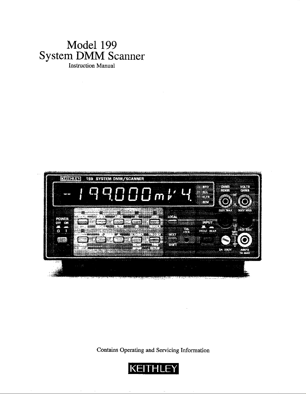
Model 199
System DMM Scanner
Instruction Manual
Contains Operating and Servicing Information
Page 2

WARRANTY
Keithley Instruments, Inc. warrants tbis product to be free from defects in material and workmanship for a period of 1 year from date of
shipment.
Keithley Instruments, Inc. warrants the following items for 90 days from the date of shipment: probes, cables, rechargeable batteries,
diskettes, and documentation.
During the warranty period, we will, at our option, either repair or replace any product that proves to be defective.
To exercise this warranty, write or call your local Keithley representative, or contact Keithley headquarters in Cleveland, Ohio. You will
be given prompt assistance and return instructions. Send the product, transportation prepaid, to the indicated service facility. Repairs
will be made and the product returned, transportation prepaid. Repaired or replaced products are warranted for the balance of the original warranty period, or at least 90 days.
LIMITATION OF WARRANTY
This warranty does not apply to defects resulting froti~product modification without Keitbley’s express written consent, or misuse of
any product ox- part. This warranty also does not apply to fuses, software, non-rechargeable batteries, damage from batteIy leakage, or
problems arising from normal wear or failure to follow instmctions.
THIS WARRANTY IS IN LIEU OF ALL OTHER WARRANTIE S, EXPRESSED OR IMPLIED. INCLUDING ANY IMPLIED
WARRANTY OF MERCHANTABILITY OR FITNESS FOR A PARTICULAR USE. THE
BUYER’S SOLE AND EXCLUSIVE REMEDIES.
NEITHER KZITHLEY INSTRUMENTS, INC. NOR ANY OF ITS EMPLOYEES SHALL BE LIABLE FOR ANY DIRBCT, INDIRECT, SPECIAL, INCIDENTAL OR CONSEQUENTIAL DAMAGES ARISING OUT OF THE USE OF ITS INSTRUMENTS AND
SOFTWARE EVEN IF KEITHLEY INSTRUMENTS, INC., HAS BEEN ADVISED IN ADVANCE OF THE POSSIBILITY OF
SUCH DAMAGES. SUCH EXCLUDED DAMAGES SHALL INCLUDE, BUT AR!? NOT LIMITED TO: COSTS OF REMOVAL
AND INSTALLATION, LOSSES SUSTAINED AS THE RESULT OF INJURY TO ANY PERSON, OR DAMAGE TO PROPERTY.
REMEDIES PROVIDED HEREIN ARE
Page 3
Model 199 System DMM Scanner
Instruction Manual
0 1988, Keith& Instruments, Inc
Test Instrumentation Group
All rights reserved.
Cleveland, Ohio, U.S.A.
July 1987, Fourth Printing
Document Number: 199-901-01 Rev. D
Page 4
SAFETY PRECAUTIONS
The following safety precautions should be observed before operating the Model 199.
This instrument is intended for use by qualified ~personnel who recognize shock hazards and are familiar
with the safety precautions required to avoid possible injury. Read over the manual carefully before operating
this instrument.
Exercise extreme caution when a shock hazard is present at the instrument’s input. The American National
Standards Institute (ANSI) states that a shock hazard exists when voltage levels greater than 3OV rms or
42.4V peak are present. A good safety practice is to expect that a hazardous voltage is present in any unknown
circuit before measuring.
Inspect the test leads for possible wear, cracks or breaks before each use. If any defects are found, replace
the test leads.
For optimum safety do not touch the test leads or the instrument while power is applied to the circuit under
test. Turn the power off and discharge all capacitors, before connecting or disconnecting the instrument.
Always disconnect all unused test leads from the instrument.
Do not touch any object which could provide a current path to the common side of the ,+cuit under test
or power line (earth) ground. Always make measurements with dry hands while standmg on a dry, insulated surface, capable of withstanding the voltage being measured.
Exercise extreme safety when~ testing high energy power circuits (AC line or mains, etc). Refer to the High
Energy Circuit Safety Precautions found in paragraph 2.6 (Basic Measurements).
Do not exceed the instrument’s maximum allowable input as defined in the~specifications and operation
section.
Page 5
cw%a wi) sdw 3a
;., ,,
Page 6
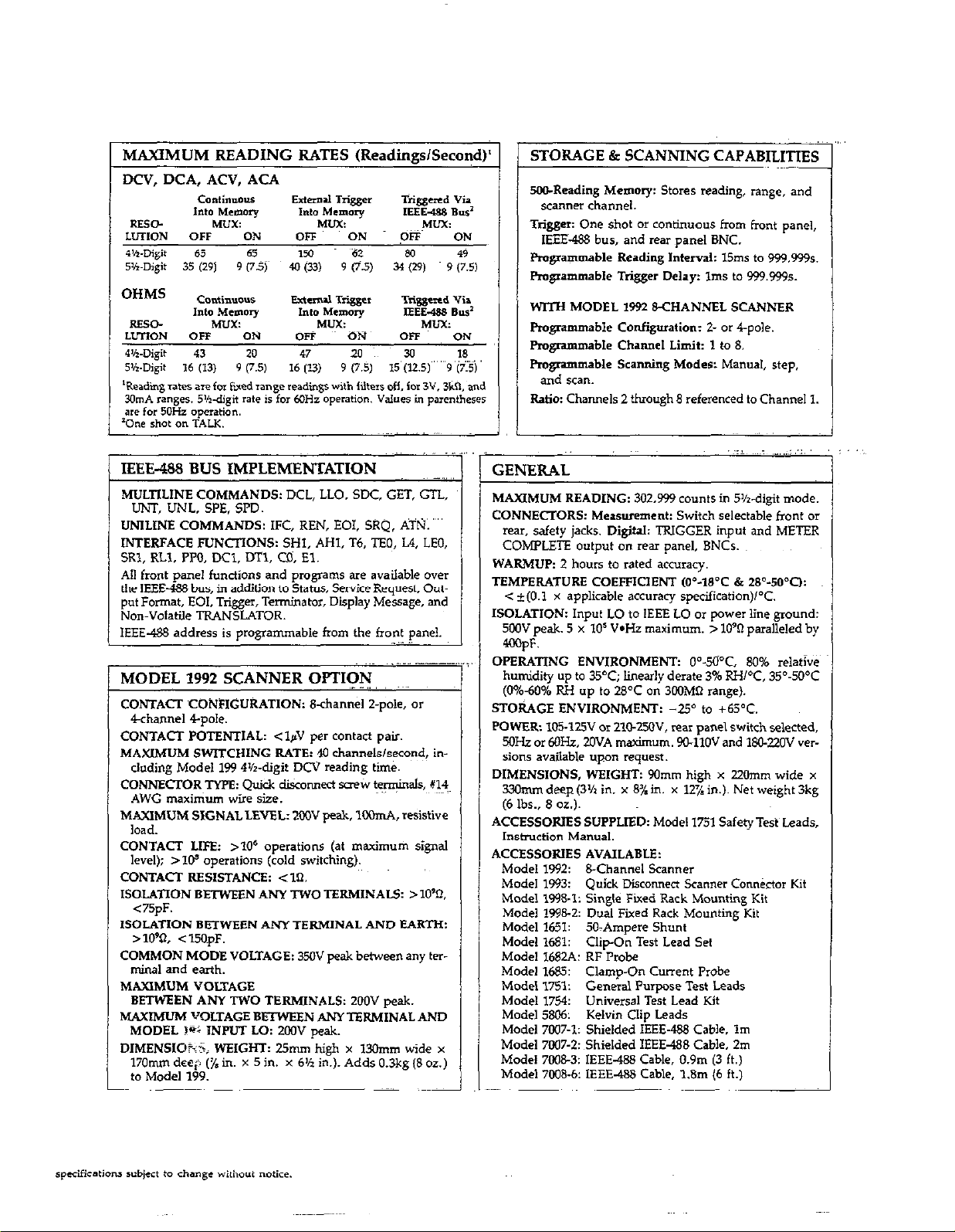
MAXIMUM READING RATES (Readings/Second)’
STORAGE & SCANNING CAPABILITIES
SO&Reading Memory: Stores reading, range, and
scanner channel.
Trigger: One shot or continuous from front pane,,
IEEE.488 bus. and rear panel BNC.
Programmable Reading Interval: 15ms to 999.999s.
Programmable Trigger Delay: Ims to 999.9995.
WITH MODEL 1992 &CHANNEL SCANNER
Pmgmmmable Configuration: t or 4-pole.
Fmgrammable Channel Limit: 1 to 8.
Pmgnmmable Scanning Moder: Manual, step,
and scan.
Ratio: Channels 2 thmugh 8 referenced to Channel 1.
IEEE-488 BUS IMPLEMENTATION
MULTILINE COMMANDS: DCL, LLO. SDC, GET, GTL,
UNT, UNL, SPE. SPD.
UNlLiNE COMMANDS: IFC, REN, EOI, SRQ. ATN.
INTERFACE FUNCIlONS: SHl, AHI, T6, TFQ, L4, LEO,
SRl, RLI. PPO, DCl, DTl, CD. El.
All front pane, functions and programs are available over
the IEEE-488 bus, in addition to Status, Swice Request, Output Format, EOI, Trigger, Terminator, Display Message, and
Non-Volatile TRANSLATOR.
IEEE-488 address is programmable from the front panel.
_ ,I
MODEL 1992 SCANNER OPTION
CONTACT CONFIGURATION: 8-channel 2-p&, or
4channel 4pole.
CONTACT POTENTIAL: <lpV per contact pair.
MAXIMUM SWITCHING RATE: 40 channels/second, in-
cluding Model 199 4’/r-digit DCV reading time.
CONNECTOR TWE: Quick disconnect screw ~y$inaIS, X’?~
AWG maximum wire size.
MAXIMUM SIGNAL LEVEL: 200” peak, lM)mA, resistive
load.
CONTACT LIFE: 210’ operations (at maximum signal
level); >I@ operations (cold switching).
CONTACT RESISTANCE: <Xl.
ISOLATION BETWEEN ANY TWO TERMINAL5 >lO%
<75pF.
lSOLATION BETWEEN ANY TERMlNAL AND EARTH:
> 10% < 15OpF.
COMMON MODE VOLTAGE: 35oV peak between any ter-
mhaf and earth.
MAXIMUM VOLTAGE
BETWEEN ANY TWO TERMINALS: 2OOV peak.
MAXIMUM VOLTAGE BEI’WEEN ANYTERMINAL AND
MODEL 19; INPUT Lo: 2oOV peak.
DIMENSIOhi; WEIGHT: 25mm hieh x 13Omm wide x
170mm deep (% in. x 5 in. x 6% ic). Adds 0.3kg (8 0~)
to Model 199.
GENERAL
MAXIMUM READING: 302,999 cmmts in SK-digit mode.
CONNECTORS: Measurement: Switch selectable front or
rear, safety jacks. DigitaL TRIGGER input and METER
COMPLET!? output on rear panel, BNCr.
WARMUP: 2 hours to rated accuracy.
TEMPERATURE COEFFICIENT ,04-18’C & 28’-50’0:
c t(O.1 x applicable accuracy sp&fication)l°C.
ISOLATION: Input LO to IEEE LO or power line ground:
5wV peak. 5 x IO’ V-Hz maximum. > lo90 paralleled by
4wpF.
OPERATING ENVIRONMENT: O”-5O”C, 80% re,ativ&
humidity up to 35°C; linearly derate 3% RH/‘C, 35”.M”C
(0%40% RH up to 28OC on 300MI-i range).
STORAGE ENVIRONMENT: -2Y to +WC.
POWER: IOS-125V or ZlC-25OV, rear panel switch selected,
5oH.z or MIHz, ZOVA maximum. 9UllOV and 180-ZOV MF
sions available upon request.
DIMENSIONS, WSIGKT: 90mm high x 220mm wide x
33hm deep (3% in. x 81 in. x 12% in.). Net weight 3kg
(6 lbs., 8 oz.).
ACCESSORlES SUPPLIED: Model ,751 Safety Test Leads,
Instruction Manual.
ACCESSORlES AVAILABLE:
Model 1992: B-Channel Scanner
Model 1993:
Model 199&l: Single Fixed Rack Mounting Kit
Model 1998-2: Dual Fixed Rack Mounting Kit
Model 1651: SO>Ampere Shunt
Model 1681:
Model 1682A: RF Probe
Model 1685: Clamp-On Curem Probe
Model 1751:
Model 1754:
Mode, 5806:
Model 7W7-1: Shielded IEEE-488 Cable. Im
Model 7007-2: Shielded IEEE-488 Cable, 2m
Model 7008-3: IEEE-488 Cable, 0.9m (3 ft.)
Model 7008.6: IEEE-488 Cable, 1.8m (6 ft.)
Quick Disconnect Scanner Conn&tor Kit
Clip-On Test Lead Set
General Purwse Test Leads
Universal T&t Lead Kit
Kelvin Clip Leads
specifications +ect to change without “otke.
Page 7
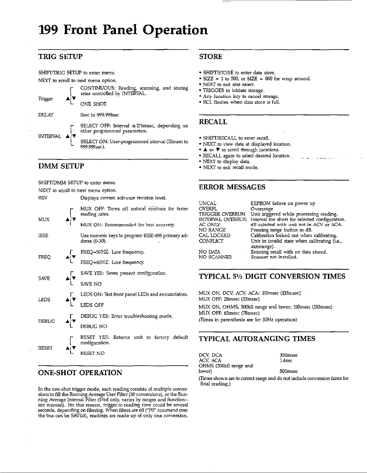
199 Front Panel Operation
TRIG SETUP
SHIFT/TRIG SETUP to enter nwnu.
NEXT to scroll to next menu option.
CONTINUOUS: Reading, scanning, and storing
rates contmlled by INTERVAL.
r
Trigger
DELAY
INTERVAL A/W
A:’
ONE SHcrT.
Osec to 999.999sec
SELECT OFF: Interval 2I75msec. depending on
other programmed parameters.
r
SELECT ON: User-pmgrammed interval (Ismsec to
L
999.9994.
DMM SETUP
SHIFUDMM SETUP to enter menu.
NEXT to scroll to next menu option,
REV
MUX
IEEE
FREQ
Displays current software revision level.
MUX OFF: Turns off autocal mufir% for faster
reading rates.
MUX ON: Recommended for best accuracy.
Use numeric keys to program IEEE-488 ptimary address (O-30).
FREQ=SOHZ. Line Frequency.
FREQ=60HZ. Line frequency.
STORE
- SHIFT/STORE to enter data store.
* SIZE = 1 to 500, or SIZE = 000 for wrap around.
* NEXT to exit size select.
- TRIGGER to initiate storage.
* Any function key to cancel storage.
- RCL flashes when data store is full.
RECALL
* SHIFURECALL to enter recall.
* NEXT to view data at displayed location.
* A or V to scroll through locations.
* RECALL again to select desired location.
- NEXT to display data.
- NEXT to exit recall mode.
ERROR MESSAGES
UNCAL
OVERFL
TRIGGER OVERRUN
INTERVAL OVERRUN
AC OI’KY
NO RANGE
CAL LOCKED
CONFIiCT
NO DATA
NO SCANNER
EEPROM failure on power up
OWTa”ge
Unit triggered while processing reading.
Interval too short for selected configuration.
dB selected with unit not in ACV or ACA.
Pressing range button in dB.
Calibration locked out when calibmtine
Unit in invalid state when calibrating &.,
autorange).
Entering recall with no data stored
Scanner not installed.
~,, ,,,, ,,
,,,
SAW
SAVE YES: Saves present configuration.
SAVE NO
LEDS ON: Test front panel LEDs and annunciators.
LEDS
LEDS OFF
DEBUG YES: Enter troubleshooting mode.
DEBUG
DEBUG NO
RESET YES: Returns unit to factory default
configuration.
NSET
RESET NO
ONE-SH(TT OPERATION
In the oneshot trigger mode, each reading consists of multiple conversions to fill the Running Average User Filter (30 canvenions), or the Running Average Internal Filter (5%d only, varies by ranges and function-see manual). For this reason, trigger-to-reading time could be several
seconds, depending on iiltering. When filters are off (‘TO” command wer
the bus can be SAvEd), readings are made up of only one conversion.
TYPICAL 5% DIGIT CONVERSION TIMES
MUX ON, DCV, ACV, AU: 1lOmsec (U3msec)
MUX OFF: Z&nsec (33msec)
MUX ON, OHMS, 3ookn range and lower: 1lOmsec (l33msec)
MUX OFF: 63msec (76msec)
(Times in parenthesis are for 50Hz operation)
TYPICAL AUTORANGING TIMES
DCV, DCA
ACV, ACA
OHMS (3OOkn range and
lower,
(Tffes shown are to coIIeCt range and do not include conversion times for
final reading.)
35amsec
1.4sec
500msec
Page 8
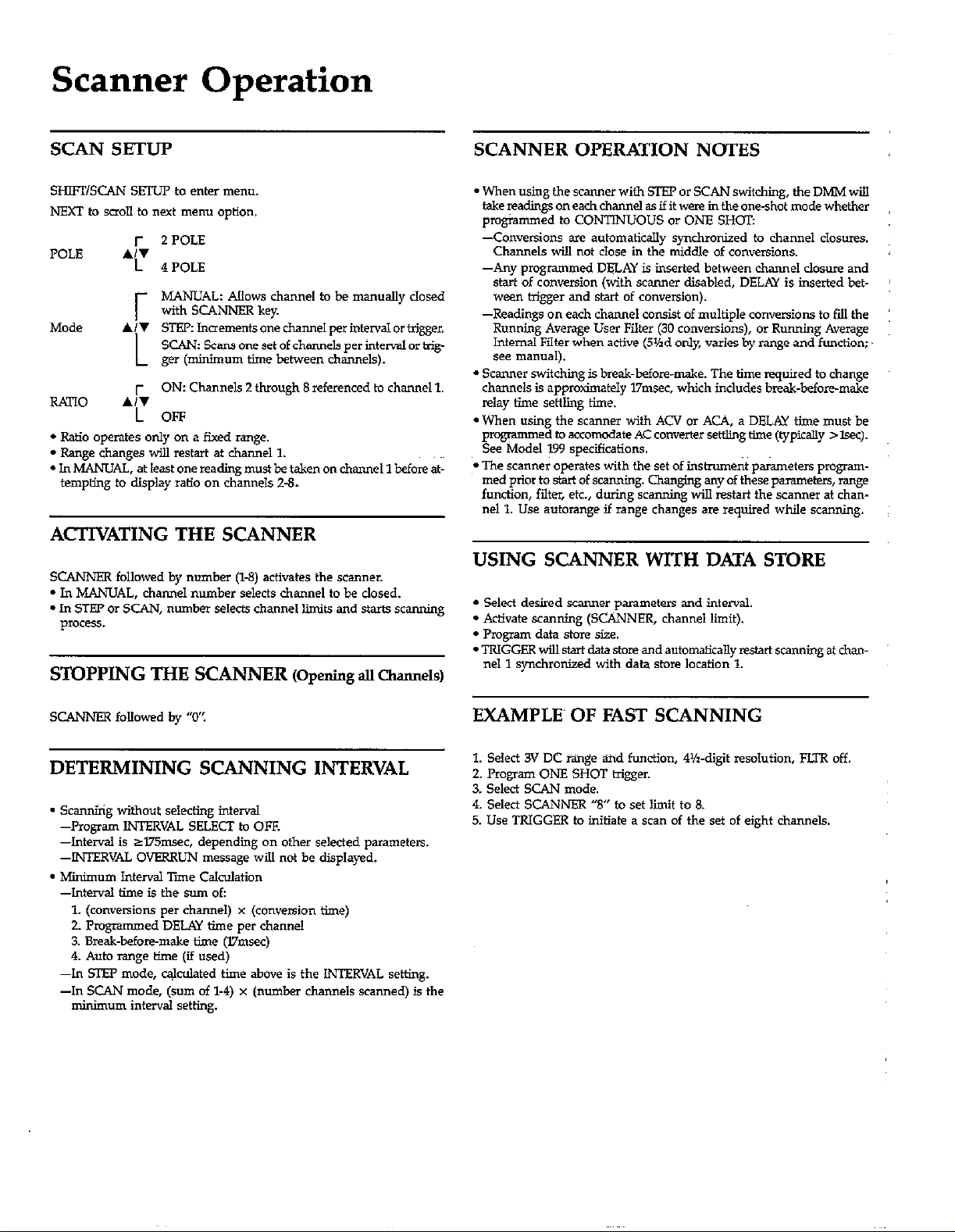
Scanner Operation
2 POLE
POLE A/T
Mode A/V
RATIO
l Ratio operates only on a fixed range.
l Range changes will restart at channel 1.
l In MANUAL, at least one reading must be taken on channel 1 before at-
tempting to display ratio on channels Z-8.
ACTIVATING THE SCANNER
SCANNER followed by number (%3) activates the scanner.
- In MANUAL, channel number selects channel to be dosed.
l In STEP or SCAN, number selects channel limits and starts scanning
process.
STOPPING THE SCANNER (opening au aam&)
r
4 POLE
MANUAL: A!lows channel to be manuaJly closed
with SCANNER key.
;
STEP: lnaements one channel perintenral or trigger,
SCAN: Scans one set of channels per interval or trig-
ger (minimum time between channels).
L
ON: Channels 2 through 8 referenced to channel 1.
*L
OFF
L
SCANNER OPERATION NOTES
l When using the sc.mner with STEP or SCAN switching, the DMM wi!J
takereading~oneachcharmel ssifit were in&one-shot mode whether
pmgmmmed to CONTlNUOUS or ONE SHOT:
-Conversions are automatically synchronized to channel closures.
Channels will not close in the middle of conversions.
-Any programmed DELAY is inserted between channel closure and
start of conversion (with scanner disabled, DELAY is inserted between trigger and start of conversion).
-Readings on each channel consist of multiple conversions to fill the
Running Average User Filter (30 conversions), 01 Running Average
Internal Filter when active (51hd only, varies by range and function;
see manual).
* Scanner switching is break-before-make. The time required to change
channels is approximately 17rwc. which includes break-before-make
relay time settling time.
l When using the scanner with ACV or ACA, a DELAY time must be
programmed to accomcdate AC converter settling time (typically >lsec).
See Model 199 sp&fications.
*The scanner operates with the set of insirument parameters program-
med prior to stat of scanning. Chanpinp any of these parameters, range
function, filter, etc., during scanning will restart the scanner at than~11. Use autorange if range changes are required while scanning.
USING SCANNER WITH DATA STORE
l Select desired scanner parameters and interval.
l Activate scanning (SCANNER, channel limit).
- Program data store size.
. TRIGGER vd, start data store and automatically restart scanning at than-
nel 1 synchronized with data store location 1.
SCANNER followed by “0’:
DETERMINING SCANNING INTERVAL
- scanning without s&ding interval
--Program INTERVAL SELECT to OFF.
-Interval is sl75msec. depending on other selected parameters.
--INTERVAL OVERRUN message wi!J not be displayed.
l Mienurn Interval Tiie Calculation
-Interval time is the sum oE
1. (conversions per channel) x (conversion time)
2. Programmed DELAY time per channel
3. Break-before-make time (17msec)
4. Auto range time (if used)
--In !XEP mode, c&l&d time above is the INTERVAL setting.
-In SCAN mode, (sum of l-4) x (number channels scanned) is the
minimum interval setting.
EXAMPLE’ OF FAST SCANNING
1. Select 3V DC range and function, 4%-d@ resolution, FLTR off.
2. Program ONE SHOT trigger.
3. Select SCAN mode.
4. Select SCANNER ‘8” to set limit to 8.
5. Use TRIGGER to initiate a scan of the set of eight channels.
Page 9
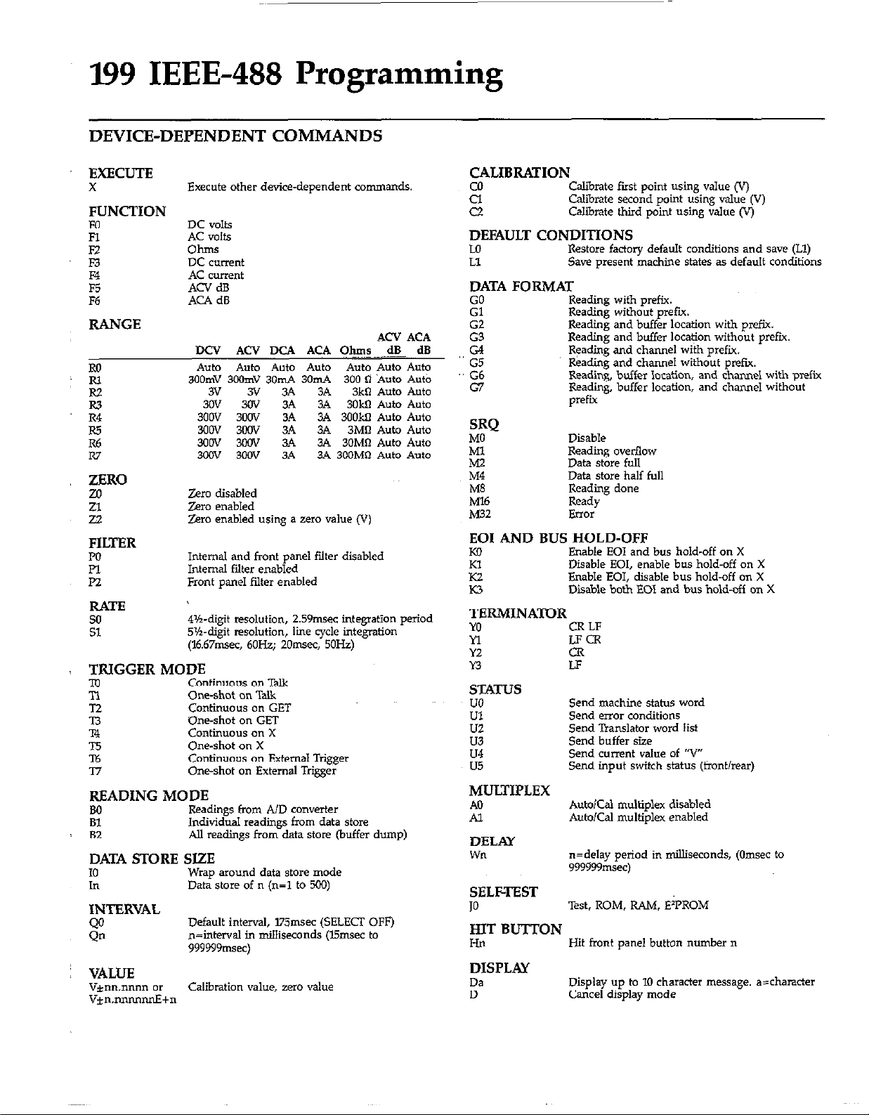
199 IEEE-488 Programming
DEVICE-DEPENDENT COMMANDS
EXECUTE
X
Execute other device-dependent commands
FUNCTION
Fo
R
F2 Ohms
53
E
F6
DC volts
AC volts
DC current
AC current
ACV dB
ACA dB
RANGE
DCV ACV DCA ACA Ohms dB dB
Ro
Auto Auto Auto Auto Auto Auto Auto
3OOmV 3WmV 3OmA 3OmA
s
R3
R4
z
R7
3V 3V 3A 3A
306’ 3OV 3A 3.4 3Okn Auto Auto
300V 300V 3A 3.4 3OOM Auto Auto
3oOV 30%’ 3A 3.4 3Mn Auto Auto
3mv 3wv 3A 3A 30MR Auto Auto
3OOV 3wV 3A
3A 3OOMO Auto Auto
ZERO
Zero disabled
Zero enabled
Zero enabled using a zero value (V)
FILTER
PO
Pl
P2
Internal and front panel filter disabled
Internal filter enabled
Front panel filter enabled
RATE
so
Sl
4%digit resolution, 2.59msec integration period
5%digit resolution, lie cycle integration
(16.67msec. 6OHz; 2Omsec, 50Hz)
TRIGGER MODE
m Continuous on Talk
n
T2
T3
T4
T5
T6
T7
READING
BO
z
One-shot on Talk
Continuous on GET
One-shot on GE?
co”tin”o”s on x
One-shot on X
Continuous on External Trigger
One-shot on External Trigger
MODE
Readings from AID converter
Individual readings from data store
All readings from data stwe (buffer dump)
DATA STORE SIZE
IO
h
Wrap around data store mode
Data store of n (n=I to 500)
INTERVAL
Q’J
Qn
Default interval, l75msec (SELECT OFF)
n=intwval in milliseconds (l5msec to
999999msec)
VALUE
v*nn.nnnn or Calibration value, zzo value
v*n.nnnnnrtE+n
A’3 ACA
300 d ‘Auto A&
3kl-i Auto Auto
CALIBRATION
co Calibrate first point using value (V)
2
Calibrate second point using r&e (V)
Cd&rate third point using value (V)
DEFAULT CONDITIONS
Lo Restore factory default conditions and save (Ll)
L* Saw present machine states as default conditions
DATA FORMAT
GO Reading with prefix.
Gl Reading without prefu.
G2 Reading and buffer location with prefix.
G3
G4
G5
G6
G7
SRQ
MO Disable
Ml Reading overflow
M2
M4 Data store half full
MB Reading done
Ml6 Ready
Reading and buffer I&ion without prefix.
Reading and channel with prefix.
Reading and channel without prefix.
Reading, buffer location, and channel with prefix
Reading, buffer location, and channel without
prefix
Data stcre full
M32 Fmx
EOI AND BUS HOLD-OFF
Ko
E
K3 Disable both EOI and bus hold-off on X
Enable EOI and bus hold-off on X
Disable SO,, enable bus hold-off on X
Enable EOI, disable bus hold-off on X
TERMINATOR
MI
ii
Y2
n
CR LF
LFCR
STATUS
UO
Ul
uz
u3
u4
u5
Send machine status word
Send error conditions
Send Translator word list
Send buffer size
Send current value of ‘?I’
Send input switch status (front/rear)
MULTIPLEX
A0
Al
AukKzd multiplez disabled
Auto/Cal multiplex enabled
DELAY
Wll
n=delay period in milliseconds, (Omsec to
999999msec)
SELFTEST
JO
Test, ROM, RAM, E?‘ROM
HIT BUTTON
HKl
Hit front pane, button number n
DISPLAY
Da Display up to 10 character message. a=character
D Cancel display made
Page 10
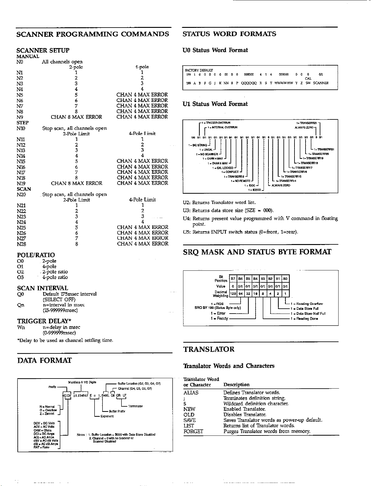
SCANNER PROGRAMMING COMMANDS
STATUS WORD FORMATS
SCANNER SETUP
MANUAL
NO
Nl
NZ
N3
N4
N5
N6
N7
N8
NY
!5lXP
NlO
Nil
NE2
Nl3
N14
Nl.5
N16
Nl7
NT3
N19
SCAN
N20
N21
N22
NW
N24
N25
N26
Au channels open
CHANgMAXERXOR
Stop scan, all channels open
Z-Pole Limit
CHAN 8 MAX ERROR
Stop scan, all channels open
Z-Pole Limit
POLE/RATIO
Z-pole
E
02
03
4-p&
Z-pole ratio
4-p& ratio
Z-pole
1
6
7
8
1
z
4
5
6
i
1
4-p&
:.
3
4
CHAN4MAXERROR
CHAN4MAXERROR
CHAN4MAXERROR
CHAN4MAXFRROR
CHAN4MAXERXOR
4Pole Limit
1
2
:
CHAN4MAXERROR
CHAN 4 MAX ERROR
CHAN 4 MAX ERROR
CHAN 4 MAX ERROR
CHAN 4 MAX ERROR
4Pole Limit
1
2
3
4
CHAN4MAXRRROR
CHAN4MAXERROR
CHAN4MAXERROR
CHAN4MAXERROR
UO Status Word Format
Ul Status Word Format
L
U2: Returns Translator word list.
U3: Returns data store size (SZE = CCQ.
U4: Returns present value programmed with V command in floating
p0illt.
u5: Returns INPLJT switch status (O=fmnt, l=rear).
SRQ MASK AND STATUS BYTE FORMAT
SCAN INTERVAL
QO
Qn
Default 175msec interval
(SELECI OFF)
n=tnterval in msec
(15.999999mxc)
TRIGGER DELAY*
wn
*Delay to be used as channel settling time.
n=delay in msec
(O-999999msec)
DATA FORMAT
TRANSLATOR
Translator Words and Characters
-miis.lator word
or character Description
ALIAS Defmes Translator words.
B
NEW Enabled Translator.
OLD
SAVE Saves Translator words as power-up default.
LIST Returns list of Translator words.
FORGET Purges Translator words from memory
Terminates definition string.
Wildcard definition character.
Disables Translator.
Page 11
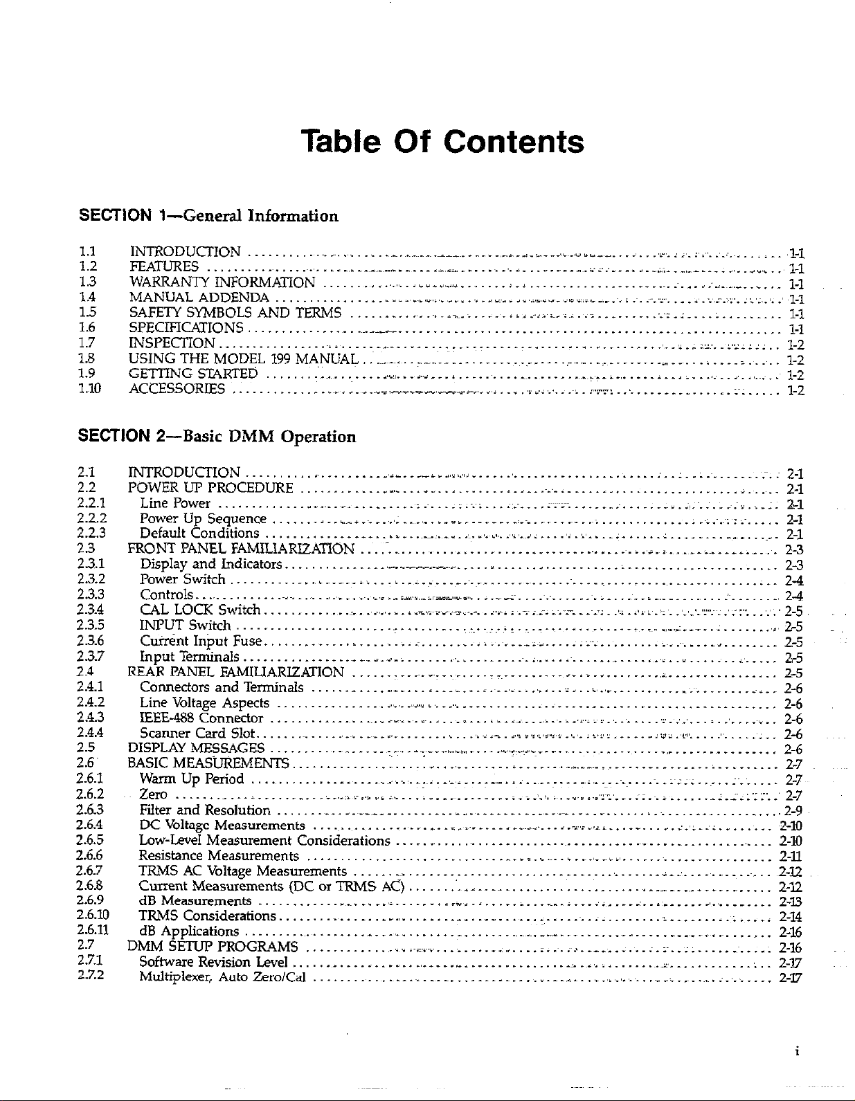
Table Of
SECTION l-General Information
Contents
1.1
1.2
1.3
1.4
1.5
1.6
1.7
1.8
1.9
1.10
INT?““-‘^“’
INTRODUCTION ~. _~. . ._.~__~__~
FE.4 FEATURES .~. _~... t . _ _.L _ ___ ~_-. ^ _ _ _
WARRANTY WARRANTY INFORMATION . . ., t..,,. . . I
MANUAL AI MANUAL ADDENDA _. . . _ __ _ .,_,_ ~.,I
SAFETY SYMBOLS AND TEE SAFETY SYMBOLS AND TERMS _ _. .~.
SPECIFICATIONS.. . . t. _ _~.~.-... . . . . . _. . . . . ._. . _. , l-1
INSPECTION ._._........_... ;.._....,.. _.._ . . . ._................... _ . . . . . . ~..;.;:~..:~z::::..
USING THE MODEL 199 MANUAL .~~.~~.~. - _.r.._ . . . . . . . . . ___. -~. . .._I. .: . . --. . -_ . .,. . i . . i
GETTING STARTED .‘:~.~. _:. <,-I.. _ a. _. i .~. . _~. _. _ .,._~_,__ j .,. . . . . i.. , i.. .,,_, I,_ .,_~i : l-2
ACCESSORIES . . . _ __._ _ ._
SECTION 2-Basic DMM Operation
2.1
2.2
2.2.1
2.22
2.2.3
2.3
23.1
2.3.2
2.3.3
2.3.4
2.3.5
2.3.6
2.3.7
2.4
2.4.1
2.4.2
24.3
2.4.4
2.5
2.6~
2.6.1
2.6.2
2.43
2.6.4
2.6.5
2.6.6
2.6.7
2.68
2.6.9
2.6.10
2.6.11
2.7
2.7.1
2.7.2
INTRODUCTION
..........
POWER UF PROCEDURE
I.
.........
............
LinePower ..................... ._
PowerUpSequence .......... .~.,..~...~.,;
Default Conditions ..............
FRONT PANEL FAMILIARIZAXTON ................................................
Display and Indicators ..............
Power Switch ............. ..___ ......
Controls ................. ._.,_ .., .......
CAL LOCK Switch ...................
INPUTSwitch.. ......................
CutintInjxtFuse.. ...............................
Input Ten&naIs . . ..___.__..._.._ A_,i_i_i___ ___...._..._... ~.i ,..., a. . . .._.~..._._. j ._~__..___ a, __._.
REARPANELFAMILIARIZQION ._._.I ~__.~_____~ _.... ~_~ . . .._.... . ..ii ._._. _ .,..,, - .____.___ L ._.._. 2-5
Connectors and Terminals . ^ t . _ . .._ _ _ . I _ _ _ ,. _ _ i .~. .,i . ,. . : , i, .,I . _ _ . . ~.‘; _ _ _ _ _ ) j _ _ 2-6
Line Voltage Aspects . . __, a,\ ._... ,+ >.. _.... ___. . . . :. . .__. _. __ _. _____ ___. _. 2-6
IEEE-488 Connector _ __ _~. .~. _ r_. . I~. . _ _ s. _. ~ . _ _~_. _ _.i . . i _ .‘,.i ii,. ,_ . . . 2:. _,_,. . ~ .‘. _~i _.
Scanner Card Slot. _~_ t .._~1 _~_ _ I;.~_. . ,~ i __ ,,.i v,i,:v: _,_,. L <.i’: t _ _ _ iri r.t*‘. . . _“. .‘: _. 2-6
DISPLAY MESSAGES . _ _ _ _ _ _ _ .:. . _ ,_,_ _ ..,_,_f _. . . . . I.,.. :a ,c_. _. .~. . . . .,. _ _ _ _ _ _ _ _. . .
BASICMEAS-iJREMENTS .__...__._..._: _.__I _.._..____... :..I _..._..._^ ~__ __...___ __.____I . . . ..I____ 2-7
WarmUpperiod .._..__ __~ ___._, j ..,._ ~_.~.._,e,L _..._,.. *a.~ ._._. - ..__ ~‘,..~~-.~-~ . . ~..:~;;;..~...;~. _____
Zero . . . . .._ __...______ _.__i_._:iil.jv/i ,.__.: ____ _....___ ;.;.‘.:r;~..r.=...“~-.‘....:.~.i ._____ ~.:.:~;:~:;‘..‘2-7
FiIterandResolution .._.. __.r____-_ _______.. _ __._..._..._ _,..~ ._..._ __ _.... __~ ______._______.... 2-9~
DC Voltage Measurements _~. . . . ._ .__~_ _ ____ I_~ .“..__. ~ji~~ii._ j..L,l.~iii_.. ___ _. i.,L-.‘l. _. . :.. 2-10
Low-Level Measurement Considerations _ _ . _ . . . . .~. . . _ _ . .._ . I . _ . _ _,. _ 2-10
Resistance Measurements _ . . . . _ _ _ . _ . _. . _ _,_ _i .,. . . . . . _ _ _ _ _ . . _ .
TRMS AC Voltage Measurements . . _~. . . . _ . . . . _. . .,. _.A-_‘. _ . . .~_ _ _~. ~2-12
Current Measurements (DC OT TRMS AC) :. ., _. __ _ . _ . . _ . _ _- _ _ _.. _ _ _ _ _ _ . . . 2-I2
dBMeasurements .._._...____ I.~__._._ ____. _.“_+, ,.L...._____ c_.j __... in ..__ ;__l~ __.____~....__,____
TRMSConsiderations . .._......__._ t_ ~_..._..__,._..__...._. r.-...~..i ___...... ,I ______.__; ._._ ~
dB Applications . .~. . . _ _. . . .,__ __,_. . . . . _ _. _. _ _~_~_~. _-__ __ . _ ._ _ _ ___ _. . .~__,_ _~. . .~_ . ,. . 2-16
DMM SETUp PROGRAMS _ . ,_.~1 l~=I~~f~. _ _ _. . _.:.I. _. i. .~. .~>_ ____. _. . _: :~. . ;. _ . . _~. _ _; 2-16
SoftwareRevisionLeveI ._...._.___ __._~ _._,____ I,_ _......_._._.... i_i,.i ._...... 1 .__...____._ :..
Multiplexer, AutoZeroiCal ..______ ~..~._____~ __.._._.. _ __.._ L .__- L...~ _,.,_ ,., . . ..__ i ___. ~...~_.. ____.
,.,_” I . 1. AU._ a i”..?/V,“7,,_.i
.l” ,asic _:_ _~;~i _:_ :‘.,?. _ _ . “ ‘.‘.;.:~:‘. I :‘;..I; .’ ,1-l
_zx~_~ . . iij.~.;ii~.i~i__i .__...-.. :.:.; _...: ..__.__._ l-1
l-2
l-2
_) _r,1513~1--11111111~1*.“,_ ..,i I ,i #i ,:. _~L z”1_: :. . ., . _ _. . . ~. .I . l-2 _
,A_..-ia..,u..,,
^
....................................................... .;
......
.‘.
...................
.:
..
1. .:.~.
......
~;~. ; 2-l
.......
2-l
........ i.~. ... :...~;...i ...... rr;:. ............. . “.*.~.;...~.;.;.;: 2-l
... .... _ ..... . ___I____. .._- .................. ;.~;.~.:::;~ ..... 2-l
_ _ ...... .~.-...~.~. .,~. .‘.~.,, .,,&,.~~. i .... ‘: L’ .... I. ..... I ........... ., ...... 2-l
_,-_-l __..--
...........................
...
..i. 2
:
......................
___~__ __ ____
...
23
2-3
__,_.i_.~ _____’ .__.. ....................................... :__ 2-4
,_.=_ lsIx “,,_ irl_ .. . .. v.r j __._ ;_ ........................ .__. .. ., .. .:~.~ .. ____, 2-4
..... j_~i~~~w~~iJ.. .. .. Ibjl ; ..:;~;~. . ..~_ . .~-,; _I~ ..l’l.:~:~. . ‘.‘.‘.‘:: . ..::“. . :::: 2-5
_.
..........
~.._~..l
..................
+.-~...- .: ____.:
........
.,2-5 I,
i_.~,__~_:~>. :~~ ..... .......... i~__~ .. .._ ......... 2-5
2-5
2-6
2-6
2-7
2-11
2-13
2-14
2-17
2-17
i
Page 12
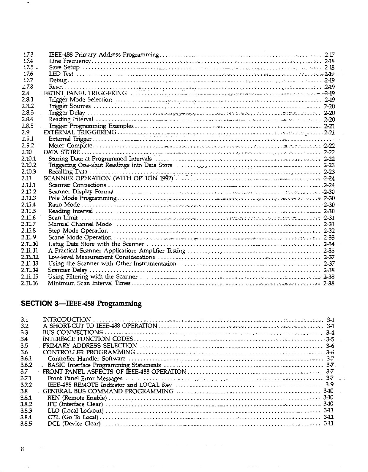
1.7.3
!.7.4
!.%5
!.7.6
!.7.7
L.7.8
2.8
2.8.1
2.8.2
2.8.3
2.8.4
2.8.5
2.9
2.9.1
2.9.2
2.10
2.10.1
2.102
2.10.3
2.11
2.11.1
2.11.2
2.113
2.11.4
2X.5
2.11.6
2.11.7
2X.8
2.11.9
2.11.10
2.11.11
2.xi2
2.ll.13~
2.11.14
2.11.15
2.X16
IEEE-488 Primary Address Programming. ............................................... . .... ._ . .. 2-17
LineFrequency.. ....... ~:.: . ..< .......... ,_, ......... . ............. ;- ... z= ......... ;..:.r-x.;; ...... ;;.,~2-18
save Setup ................ ._~_ .... ... ._~_, ........ _~. . _. . * .~._ “_.~ ..,..^ ..... i,_ > ., . ,.___ ... I,. . .i#i . -,. _‘,,.l i 2-18
LEDTest ............................... i__~__ .,-.I_ .. .._.~..z.< . ,r_., d ., ......... i~.J<.i __ . ..!. ..... ;...;L..,2-19
Debug.. ............................... .._..._~ ___.___.__, . .,._ ~..r..~...; ...... i ..... .;.....;..ii. .A___ .a-19
Reset.. ....................... I .... L ........... i.~. ... r- ___.; .... -~+ . ..< .........
FRONT PANELTRIGGERING ..‘.~:~..:......~.-.t..~..~.....~~~.~;,.,
Trigger Mode Selection .............. _,__,,L ,.,__ _,,_ ., .......... --. .............. ._. .................. _j~:__ 2-19
TriggeT Sources ....... : ........ .,_~. ..... .~:. .; ......... __~_, ..... _ ................ __ ........... 2-20
,Trigger Delay
Reading Interval ......... ., ...... _f __ .. _._, _ ..i. ..... _.,i _,,i .. _ . _, . .,, ... I, i ,-,I,, ;. ,_,_ ,, . w_ ; .. ,_ 7: .I. :‘.I ,I .. .‘. ... 2-20
Trigger Programming Examples ....... I. .................. .~j.r .. . .. &. ;_ : .., ii ... >~.,; . ~..i.;~~~-.~. .; ._,_, 11,2-21
EXTERNAL TRIGGERING. ..... ~__~.~.~t~__~_ .___ _~ .... ~.https://manualmachine.com/~ .... ....... ....... ;..i.:..‘..~_~.i.~i. ‘2-U
External Trigger. .................
Meter Complete .....................
D.QA STORE .................... __ .... _ ii_ ..,I i <,w,tis. i,.: ..... : _ ..... > i .+. i p.~i .......... .i :_ ... ,A. . .,., .. 2-22
StoringDataatProgrammedIntervals ......... ~.~..~rl._~ _ ......... ~~...i~.__~. ..... ,.t_.-i.,:i:,.,_,j....i .l 2-22
Triggeri?g One-s&t Readings into Data Store _~_~_, .t. _,_ . __ ‘,....,‘-...~ -. ....... Z-3
Recalling Data
SCz4NNE.R OPERATION (WITH OrrION 1942)’ :~;. : : .... 1
ScannerConnections...~ ............................. _~ .. .._...._. ~_~~ ........... _._ .............. b,d.,2-24
Scanner Display Format ....... ^~_ .......... ., .. _, ., . ; .,,_ ... j : .. :‘. I :,.‘~. .:.~‘.‘. :I .... _,_ .. :I’.‘,..:.:. .., .. _;;_ ..2- 30
Pole Mode Programming. ............ .,.,__ ~,IL.~.I-z,~~ ., .... ..~jli,Y~j,_lY,....~. ... i CL/, i :_ -~-,-.‘~:.‘.Y::~ .‘.‘:. :X 2-30
RatioMode.. ............. ................~ ....... _,I.II,_ ., . -I .,..., ;_.,._~ ........ . .................. :.;2-30
Reading Interval ..................................... .~L ........ ,_,,._ .............. .___I.: ..... ~_:____~._ 2-30
Scan Limit .................... I .. j ... ,_ i zii; ., . .pYYi..rpz,, ..... _ . 1 . ‘~ r~.:.:;:.r:: .:_‘: 1’. i :. . I I . L:‘:‘.‘.:L. ... ‘_ ?~ I ‘1: ,,2-31
Manual Channel Mode.. ........ .._. ~__~ ........................... i .... L:~ ...... :_~_,_~ .... ....... 2-31
Step Mode Operation .......... I ......... ...~.ii. ... .._. ....................... ;_ . _.- _: ..‘: ... i .. 2-32
Sane’ Mode Operation .......... ., ........ _,l.il_,_ _,-._ _ . I .... _i,.~-__, . _.-~.i_,L1._,j,i,_,__~.~_ .... i_ _,:> .‘.: .... 2: . 2-33
Using Data Store with the Scanner.. .......... ................. I~__L .... A~_ ...... ~..I..j..,I..i,...ij. ,2-34
A Practical Scanner Application: Amplifier Testing .......... __ .... .~- __ .......... __
Lw+level Measurement Considerations ............. _ ..... , ................. ,*,, ................... 2-37
Using the Scanner with Other Instrumentation ............. .,_. _ ................................ ., . 2-37
Scanner Delay.. ......................................................... ~__* ..................... 2-38
Using Filtering with the Scam-w
Minimum Scan Interval Ties. ...
...................
.................... ., ........ _, .............. __ ..
:_ . e ‘v, ,‘:~:,‘:*~‘s~:~,“‘.~:u.)
__ .. .~.:.,I:.:,.~. _:
.......................
,._.__.” ... ._.. ‘ ,.__., i.,il_ ,., i‘~“~_~~~” ___, 1L.-‘,--,-IL.,i,~~~~..~~:..,...111’--.-2~ .
.... ................
~____iY_~.iii.i_j~i~i_~i~_~__~jj_~iii~~~:I~_~~._.L~i_~
..........................
.. .... _ .. 11 _~_ ... i .... i ,>.> _,/u,./j,/ . j .., .. ,> . i_: .. ,224
.....
, ......... ii~ .... i .. ‘. _, ..; .~. ., ..... ;- _._,__ ....... :;,:.2-38
* -8, ; -,A 1_ rj ,>,,>,,i . _ ......... 2% :: ;~_I L.,., . ,.‘. : J -!.‘&-lg
.
...
i,._ ,_ ..~.LI’::.z
‘.l.~l...‘.
.,.., .... _ ........... ._ . _: _,_ ....... 2-23
1 :‘.u~/
...............
,
... i ....
‘.,
....
:l-.‘;.~-~: ____ :..,% l9
......
.zz. :‘,.i_ :I :‘Y,
......
i
i .................
I,.--.~-~,~:-~r,.‘.:.l,~r.,2-22
.......
_ . ._ .. 235
...
“2-20
SECTION 3-IEEE-488 Programming
3.1
3.2
3.3
3.4 INTERFACEFUNCTIONCODES
3.5 PRIMARY ADDRESS SELECTION ....... _ ................... _.,_ . _ ... __ ... 1, _,_ .................. ., 3-6
3.6 CONTROLLERPROGRAh4MING.. .......
3.61
3.6.2 ... BASIC Interface Programming Statements ............................... __ .. _ .... .__ ......... _._ 31
3.7 FRONT PANEL ASPECTS OF IEEE-488 OPERATION. ..................................... -. ...... 3-7
3.7.1 FrontPanelEnorMessages ..........................................................
3.7.2 IEEE-488 REMOTE Indicator and LOCAL Key .................................................. 3-9
3.8 GENERAL BUS COMMAND PROGRAMMING
3.8.1 REN(RemoteEnabIe) ............... _, ..........................................................
3.8.2
3.8.3
3.8.4
3.8.5 DCL (Device Clear) ..................
ii
INTRODUCTION ............... .._ .......... L,l_ii_i ............ :_:__/ ..__...__._ ..... :i..:..:.e..;-.r. 3-l
A SHORTCUT TO IEEE-488 OPERATION. ........... _ .......... _,I.,_ .... ..e..u .. .,_ < ... ..A. .. _._ ..L.....~ ... >~.‘:z .... 3-l
BUSCO~NNECTIONS ............................... .............................. ___., ......... 3-4
.........
CotitroIIer Handler Software ........ ..,
IFC (InterfaceClear) .................. . ........... ____ _______,_,___
LLO (Local Lockout)
GTL(GoToLxaI) .......................... ._,,__, 1.~ _,___ ____: ...... pi ............... ;.:A.-.~. ..... 3-11
......................
_ __I__._
~.I.~.~____
............................................. ..~_~_~._~._
..c ... , . ._,
..... . . _
................................
..................
..............
i
.....
....
-__ _,__ . ______
......
~v.__.~
....
_
~._.~,~__ _._.r ..... . . . ........ ..~3- 5
...
_._,____(_ . .__, 3-6
i...~
.........
...................
_, i,.
.............. _&_~
.............................
., . _
..............................
........
.......
-.
_,._,i, ..... . 3-10
.... - ...
3-7
~3-7
3-10
3~10
3-11
3-11
Page 13
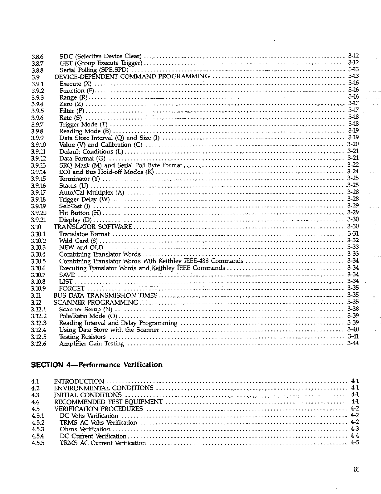
3.8.6
~~1
,,,,
3.8.7
3.88
3.9
3.9.1
3.92
3.9.3
3.9.4
3.9.5
3.%6
3.9.7
3.9.8
3.9.9
3.9.10
29.11
3.922
3.9.u
3.9.14
3.9.15
3.9.16
3.9.17
3.9.18
3.9.19
3.9.20
3.9.21
3.10
3.10.1
3.10.2
3.10.3
110.4
3.10.5
3.10.6
3.10.7
3.10.8
3.10.9
3.11
3.12
3x.1
3.12.2
3.12.3
3.12.4
3.12.5
3.12.6
SDC (Selective Device Clear)
GET (Group Execute Trigger)
...........
_ _
.......
.................................
...........
:
_,
..
...................
_,_
..
............
_
_.
SerialPoJIiig(SPE,SPD) ...................... .._. ______ I .._._.._ ... _ ._._.._ ...........
DEVICE-DEPENDE&T COMMAND PROGRAMMING
Exe&e(X) ........................... ::...: .... .................. ,_____
Fumtion (F). ..... ..~_.._
......
I..._
...
~___
.....................................
....................
._
_.
........................
Range(R). .................. ~..~_-.~...~_ .... _ ................................................
Zero(Z) .............................. ~_. ..............
Filter (I’).
Rate (S)
TriggerMode(T
Reading Mode (B)
Data Store Interval(Q) and Size (I)
Value (V) and Calibration (C)
DefaultC&ditions(L).
Data Format (G)
SRQ Mask (M) and Serial Poll Byte Format _
EOI and Bus Hold-off Modes (K)
Terminator (Y)
...................
.....................
.....
................................
._~__ .~_ ._~.~..~_...._. _.
..; ~,_,-
.............................
................................
.................................
...................................
......................................
,
.......
.._._ .._ I._.~
.
............
............................. _. ................ _
..............................................
_,_ . _
.......
.._. r ..
.._..._ _:.
..... _ ..............
__~:~<
................................
.............................
_
..
.~..~~_.
...........
...................
,__^_ _ .__________.__ ___ ____,,__ _____._____ 3-18
...
_
...
__ _
...
_._.
.....................................
^_
...
_ _
...........................
........................
_
........
____
-.
__._
...............
Status(U). ......................... ~_~___. ....................................................
Auto/Cal Multiplex (A)
Trigger Delay (W)
Self-Test(J)
Hit Button (H)
Display(D).
..................................
............................................
...................................................
..........................
..........................................
TRANSLATORSOFTWARE ......... ._______ _.~
Translatoe Format
Wild Card ($)
NEW and OLD
................
..................................
................................. _ ...... ..:.
CombiningTranslator Words
.........................................
_~.
........
...........
_:
................... _~.
.
.._
...
.........................
..................................
..__.
________.______._______,_ _,_______._____._______ 3-32
Combining Translator Words With Keithley IEEE-488 Comniarids
Executing Translator Words a& Keithley IEEE Commands
SAVE
LIST..
.......................
....................
_.
FORGET .................... ~;..~
BUS DATA TRANSMISSION TIMES ...
SCANNER PROGRAMMING
Scanner Setup (N)
Pole/Ratio Mode (0).
..........................................
.........................
: ................
Reading Interval and Delay Programming
Using Data Store with the Scanner
Testing Resistors
.............................
Amplifier Gain Testing ..... _~~; :,
....
..____
:..-:...,.e~, _._____ ___I_ .~~..-._--..-.-.-----
............ _._._~ ........ - .... .._
.._ ........ ~..~.w..:..: ..
...
,_ _ ,_r T_ . _~_~_ _ I _ _
., .._. _. . _ _ . .z._
..
__~__ .. __~_. __ ...........................
..................
_~.
............... ., ...............................
..............................................
...
..
_
_. _
.............................................................
~_.
,_
..
..........
_.__._._. __.
__ __
_ . __.
..
__
.. _ ..
.._
..
..................................
........
...
................
_.
..............
_
.
...................
.................................. 3-33
.:
__~
.......
...................... , ......... 3-34
..........................
_~
.............................
_ _.._......._...___ _ _ __._
...
...
_.
_
._ . __
......
.,
............
_
...........
.........
_~.
_.
..........
......................
.._ .._ _
......
.......
__
......
.,
_.l..
..............
,
.....
.._ .. _.
.___
............
_.
__.
...............
........
.......
_. _,T _i__. _ _~. i_.
......
_“. . _.
..... _ ... _ ..
:
...
,
_ .._ _
~..__. 3-W
...
..........
:?_
...
............
,
.......
_
......
_ _.
..
: ;
-...~
....
...
...
3-20
3-21
~..~...:
_
...
3-21
.......
3-22
3-24
..
__,L_,_,_
3-25
_ .3-25
_~_ . __._,_
....
., . 3-28
3-28
. ... _. 3-29
....
.........
>.
.... _ ..
_ ., 3-29
3-30
::...;~3-3 0
...........
_.
3-31
3-33
3-34
............ 3-34
*?
3-34~.
...
3-35
..
.....
.. _ .
_ 335~
_ 3-35
__- ., _,_, _._m
.~_. :.
__ _ ___. ._ _. 3-38
.....
3-39
__~_ __ _ 3-39
...........
._
..........
3-40
3-41
:_ 3-44
3-12
3-12
3-13
3-16
3-16
3-16 ~‘~
3-17
3-17
3-J.8
3-19
3-19
......
...
SECTION 4-Performance Verification
4.1
4.2
INTRODUCTION ...............
ENVIRONMENTAL CONDITIONS
4.3 INITIALCONDITIONS ....................... .1._
4.4
4.5
4.5.1
4.5.2
4.5.3
4.5.4
4.55
RECOMMENDED TEST EQUIPMENT ........ :
VERIFICATION PROCEDURES
DC Volts Verification
.............................................................
TRMS AC Volts Verifications ........... .‘.~_
Ohms Verification .............................. _~_~___
DC Current Verification, ............... _.
TRMS AC Current Verification
...............................................................
..... _ ..........
......
...................................................................
......................................................
.......................................
............................................
.....
__
.........
.........................
:
....
_.~__.
....
...
_~
_,
..
.....................................
.,.,_
.. _ ..........................
__
...
I~...J _.
_. ................ .._.
_,_
.....
.,
...............
._
............
...........
_,
............
,
...
.,
4-1
4-l
.....
4-l
4-1
4-2
4-2
4-2
4-3
4-4
_.,_. 4-5
u1
Page 14
SECTION 5-Principles of Operation
5.1
5.2
5.3
5.3-l
5.32 Multiplexer
5.3.3
513.4~~~
5.4
5.5
5.6 : DIGITALCIRCUITRY .__.____tt__ ::w..~.-. _____,_.: ___,_. _ ,_..______,_ ~ .~_.~______ L ._t____...; ____._,,. ;v_._ 5-10
5.6.1
5.6.2
5.7
5.8 SCANNER . . . . . . . . . .._.._.....~..... ~ ,_______. _...,. L . . .._.-__I_.._, _.I ._..._.... 2 .._...._..__..... 5-10
58.1
5.8.2
INTRODUCTION . . . .._......__._ >.,i_<~r...~ ___r..... 1,__ . . . . . . . . . . . . ..____._..~...... a,>_,,y __,. ;:i~;l,:~;~i~5.1
OVERALLFUNCTIONALDESCRII’TION ___......_....._... _ .I-., _,_.._.__.__ .__.._. _ .___.. I,_.~.._.,.
ANALOG CIRCUITRY.. . _. ..__I __-_ __~_~A __~_I_.. _. _ _ ..,. ii,_,. .~_ _ z _. . :.‘I-. _. _ .~.,. _. 5-l
InputSignalConditioning .._.. .._._. _~_I ,._._ 1 . . . . . . ~,I ..-.-. i_i~ . . . . . i _.._ ;.)I’..;~.:.’ _.._ i_i_.
-28V Reference Source . ~. . ~. : .~. : ;.::~. . . . . _ .,-._
InputBufferAmplifier . . . . . . !.~.I ..____..... _ ..,.......... 2 . . . . . . . . i . . . . . ..__....____ ~_i.,_,.. 5-8
A/D CONVERTER
~~~:CONTROLCIRCUITRY ~.~.~.,.<..;z .__....__. > ,...-,.... i.i..~...~._ . . . . . . . . . . :..:..i~ . .._.... ‘1.
Microcomputer . . . .._.._.._..____... ~_~i__,ij .,_. Ijj,__,,j’ . . . . . . . . . . l_-~._..;_;..: . . . . . . . . z..:;..;..;...
Display Circuitry . ; _ _ -1-i ,“.., I . . . .._. _ ___,_ _ , . . :-.: .;~.-- _. .~_~_ j~l~_l, ;. .~_ .‘+z.. .:: :. . . .,. &lO
POWERSUI’I’LIES _.,__..; .__.__ :..~:.. ._...___ __.. I).~ .._._._ -~.~.-..I...:..;..~ __._.I :._.i _,,.._.__ ~5-IC
c0ntr01cicnilTy . . . . . . . . . ..___. _... -.~..~~-;.~.~-~~,~...~ ,........ ~_.~.i ~....___.....____.. ..,_ _ . . . . . . . .
Switching Relays . . . . I. _ . _ a~.~. .z: __. i,. i.i. ._ _ . _.i .~:; . i: . . . . I._. _ ) ;~: .~xr:~. . _. . S-11
.._.....,_. __._,_,_. _~_.~._._~______~..,_ _~.......___....._.___. ..__ ____ ____ i...:.....1=~~5-8
/ . . . . iii _........__ r.‘.;. ______^___ ~_iii_~ ____
5.1
5-1
. ~5-6
~5.8
5-10
5-10
5-10
SECTION 6-Maintenance
6.1
6.2
6.3
6.3.1
6.3.2
6.4
6.4.1
6.4.2
6.4.3 ..
6.4.4
6.4.5
6.4.6
6.41
6.4.8
6.4.9
6.4.10
6.& DCC
6.5.
6.6 SPECIAL HANDLING
6.7 TROUBLESHOOTING
67.1
6.7.2 ..
6.7.3
6.%4
6.7.5
6.76
6.7.7
6.8 ~SCANNERINSTALLATIONANDCHECKOUT.
6.8.1
6.8.2
6.8.3
INTRODUCTION
LINEVOLTAGESELECTION
FUSEREPLACEMENT
LineFuse ....................... . ..-L......i.~~..............~:~~~:
Current FU
CALIBRATION
Recommended Calibration Equipment
Environmental Conditions
Warm-UpPeriod.. ......................
CAL Lock Switch .............. ,.,_ _, _ L ., _
Front Panel Calibration ............ ...._:
IEEE-488 Bus Calibration
Calibration Sequence .....................
DCVoltsCalibration..
Resistance C&&ration ....................
TRMSACVoltsCalibration ...... ........
unrent Calibration ......... ~.,~“~.-~ ........
TRMS AC Current Calibration ...........
DISASSEMBLY INSTRUCTIONS..
Recommended Test Equipment ..................
I’owerUpSeIfTest ............. _.._. _._--,.L~.i.~~__~~i,.~
Diagnostics ............ .._.__ .....................
PowerStipplies.. ....................
Signal Conditioning Checks ............ _ _ ....... . .-
DigitalandDisplayCircuitryChecks..
Scanner Checks.. .............. .~...~__.__ _ _
Installation .......................... _ ............
Card Checkout .....................................................
Relay Shield Jumper ..................
................ .t......_
.............
.......... ~.,.-.; ._ 1.;
se ..................... L .......................
............. _^__ .. .~.I;~._.~
...
: . .~; :~.~:::~I.
...........................
........................
.............................
................
... __., i ,a,_ :i..> .: ..i.:.;; .. _‘i .... ._I’., ..:.... L.‘:.-,:,-:-~
..I: ... . ............ ._ .............
..... ;...:.~..:..A:.1 ............ l,i~irl_ii_,i,i.~.ii_._‘_1.
..... ;~_; .,._ ... . ..
.._ .. i ._.__ f.. ... _ ...............
........ _._ _ ......... ;: : ........... I..:.
...........
..
:_ili.. .. ~.i. ... . ................................
... _yy_~I _ jmj.i .... i .. j i~i ..* :.. _ ....~..~.L~...~. ... i
......... . . ... .
._ ................. _. ..... .,,_ ,, .... _ ..
L.. .. l.. ................ ....t...ii ..__ _. ..;: ....... _ ....... _ 2,
_ .............. i _.__ .._._. _,.,_ .. _~.,:
.......
.~:~I
_.____.^ .~.........._. .: .__, L___ .... __I
..... _._ .... ji,. .............................
.
............
;. : ... __ ........ . ........ _,.;, ___
._ _ .~i,l.Lj.l .
_ . .._
_ ............ . pi .~i i.
. .................. __,_._______
....
._I,, _
,_.,_ ............
....
~=.;. ..... _
..... ____., i _.___ __w,i_~/.
........
.___ ,i .......... .._.
_.
......................
._
..... . ..
.
...............
.....
._,__ _._i~_.i_.
_. ... ..___ _ i.__._-__.iz~
_..i.....l.i.....l.._i_ i .....
............
::.
..... I ..............................
,__L.__~. ..... ..~.....‘....‘~~~.i.‘.~.......‘.:.’.:’.~..l. 6-5
i:.
..
......................
+ ........... . ..................
............................
....
Il~_~_~.~i
.... ..^ ._ i ........ ;..e_
............................
_,_ ...... .__ ___ .
:.
..i
................
.....
_._& ..................
i;. .,_,_, -.----T.i~...-..L~~ ..- 6-1
..~~....~..~..11.... ........... 6-1
....... c. -.-:.‘:a; .... 1~: .... 6-2
........................ 6-2
; :. ; __:
.. _ _ -‘: ;.r: .z: : . : . ; ..... 6-3
.~.+ ;.. ....
..
......... .,_ ...... ..; .... 1’: 6-12
.... L ... ii :..::z:.:
.....
..... i ....
i_
. ..__ .. -..;..~.:.~..:. 6-l8
..... .._ ............ 6-18
;.: ._. ......
.......
.: ............. 6-3
.*.
, _._ .. _,_ .; L __ : .. ‘L #,,., jl, 6-5
., _:_ ...... _~; . ; 6-6
..... .:..~ ........... 6-12
__._ ......... ~.~..6-17.
.._._; _ ...... ~;.;....~6- 17
..L. _._
. ___._._.__._ 6-18
.___.__ ii._i,_i_i 6-18
.._. izi,.__ ...... .._
.;-
_._.
........
....... 6-l
.... ~61
_i ....... 6-2
......
:
............
L.. .. ~...6- I3
.............
_‘*._ _‘wr~_:_ ~6-17
...........
...........
i ......... 6-23
:~ 6-3
I 6-v
6-18
..
6-22
6-22
; .... 6-24
6-3
6-4
6-8
iv
Page 15
SECTION 7-Replaceable Parts
7.1.
7.2
7.3
7.4
7.5
INTRODUCTION ..........................
PARTS LIST
ORDERING INFORMATION
FACTORY SERVICE
SCHEMATIC DIAGRAMS AND COMPONENT LOCATION ~DRKWINGS
APPENDIX A
ASCII CHARACTER CODES AND TEEE-188~ MULTILINE INTERFACE COMMAND MESSAGES _ . . A-l
APPENDIX B
CONTROLLER PROGRAMS _~. ~._ . . . . . _ . _ . t . . . . . _ _ ___ _ _ _ _ _,. L . _,_ B-l
APPENDIX C
IEEE-488 BUS OVERVIEW :. : .:: :: ,. .: .‘. : :. r . . . . . . . _ . . _~. _ _ , . :
................... ~.~.~...:~..~:
..........................................................................
.................................
l,_ ....... ..1~.
..... ,,--..-.-. .:. ........ _.-._ .---- . .
_ .................................
....
., L.II II~,.~.
: .,
.
.......
.... : ..............
.,.~. ..... ,.“i _I: ,, .1
.........
..I,
.................
.._,“.
i _., _.ii i: i _~_;~ 7-1
... . “....~L
;. ...... 7-1
7-l
..
7-1
7-1
C-l
Page 16
List Of Illustrations
SECTION 2-Basic DMM Operation
2-l
2-2
2-3
2-4
2-5
2-6
2-7
2-8
2-9
2-10
2-u
2-12
2-13
2-14
2-15
2-16
2-w
Model 199 Front Panel. ...........................................................................
Model 199 Rear Panel ........................................................
DCVoltageMeasurements
Two-Terminal Resistance Measurements.
Four-Terminal Resistance Measurements
TRh4S AC Voltage Measurement .........................................................
Current Measurements..
External Trigger Pulse Specifications
Meter Complete Pulse SpecifZations.
Scanner Connections
Output Cable Connections ........................................................
Voltage Test Connections ;
2-l’& Resistor Test Connections
4-P&? Resistor Test Connections.
Amplifier Gain Test Configuration.
Amplifier Frequency Response Test Configuration
Using Scanner Card with Nanovoltmeter
...................
.......................................................................
.............................................
.... (.
....................
............
.I.
............
.......
...............................................
_ .................
................................................
..........................................................
...................................................
:
................................
....................................
: .................
.Lz
.............
....................................
............................................................
:.
_
. ............... _ _,__ ~__ ...
...
__
:
................
.................................
,~ _ __
.........
_:: _~:L_
L
..
.................
.._ .._ 2-10
_
....... _ .
.
........
,
_
.............
..
__~_ .~._.~_._ _- _~__, 2-24
..~. .~.~_, ..... _ ....
..L. L.~.~
.....
_~_ __ ___
___ _____. _ 2-28
L .;
L_
...
__
__ __
........
.........
......
..
2-3
2-s
2-11
2-11
2-12
2.12
2-21
_,_ ,,., Z-22
2-26
2-27
..:-..2-2 9
2-35
2-36
2-39
SECTION 3-IEEE-488 Programming
3-l Typical Program Flow Chart _. .~.~. . .~_. .~. . .~. . _ _. _ _ ___ _ 3-2
3-2 IEEE-488 Connector _ :Y: .: .~. ._ . .~. . _ :
3-3 IEEE-488 Connections . . . . . . . . . _ . . . _. . .~. _. .~_.~_~_ __- _ _. _ . . _ _ 3-4
3-4
3-5 ContactAssignments _____._._r.~.__...~ _.._ _.__ _ I______ ~ _.__. _ . . . . . . ^ _.... I._ .___. _L _________..,___. 3-5
3-6 General Dat Format . . . _ . . . . . . . . t _ .._ 3-22
37 SRQ Mask and Serial Poll Byte Format .~. :_ . ~ _. _. . . 3-23
3-8 UO Machine Status Word and Default Values . ..__. . .,.... ~..~ .,.,.. . . . . . . . . . . __ ________ ~-~3-26
3-9 UlErrorStatusWord . . . . ..___......_._........... ^ . .._... ^_I..~ . . . . . . . _._____ ____..___.. ~,_-I_ 3-27
3-10 2-l’& Resistor Test Connections : . . .~. .~; : .~. . .~. .~. . : . ; .~. 1 _.~~.
3-n 4-P& Resistor test Connections .+; .;. _ ., . . . 3-43
3-12 Amplifier Gain Test Configurations I 1’:. _~_ 1 . .‘. _ _‘. ._~. .‘I 1. 1.‘. 1 _ I _ 1.. _‘_ . _ _,_, 1. _ _ _‘_ 346
IEEE-488 Connector Location. .~. . . .~.. _. . . ,. . .~. . . _. _. . _. . 3-5
3-4
3-42
SECTION 4-Performance Verification
4-l Connections for DC VoltsVerification . . . . . . . . . ..___ I __________.___._._ 1 _____ _ ..___-._ ~_~ ._.,_ ~...~4-2
4-2 Connections for TRMS AC Volts Verification.. :‘. :. , . _. . I~. . . . .~. . . __ _. 4-3
4-3 Connections for Ohms Verification (300%3Ok0 Range). . . . 4-4
44
4-5 Connections for DC Current Verification _ . _ . . _. . . , 4-5
4-6 Connections for TRMS AC Current Verification .~. . . 4-5
Connections for Ohms Verification (300kil-3OOM0 Ranges) . .~. .~. . 4-4
vii
Page 17
SECTION t&-Principles of Operation
5-l &&all Block Diagram . _ _ _. ~.,,- _ _ .._ .~~II_ _ _. _:*,. I;-.,. _ . :. . . . *.. ., .,_ <:I, i i _ . . i:. . . . _ _ . _; :; 5-2
5-2 Input Configurati& During 2 and 4-terminal Resistance~Measurement, . _ _.. . . _ _ . _ _ _ _. I _ . . . _. S-4
5-3 ~: ResistanceMeasurementSimplIfiedCircuitry _....._, _ _.__....__..... Lji,.i__.j .___. ii:....i~rl.‘.l’,~;. 5-5
5-4 JFET MuliipIexer . . . . . . _ . . . _ _, _,_ _,_ __ ,_ _ . . . . .~.~. . _. _. _ _,_ <.<,,I * .~_ 2 . _ _ i,,. .’ .:;: i ii i ‘2% : :‘i:~. 5-6
5-5 MultiplexerPhases _........._,._ _ ,.__. ___~_~.~~,ll~.~.__~I.._..__ _._. j _...._ \~..> . . . . . . . ..____. . . . . . . . . ~.. 5-7
5-6 A/D Conveitei Simplified Schematic. _ . . . . _ _ _ . . . _ . . . _ . . . ,. _ _ ;. . . _~~. ,, I . , . _ _
5-9
SECTION 6-Maintenance
DCVoltsCalibrationConfiguration(3CQmV~nge) __..____..._ ‘I.... ,.=. . . ...1.-.* __,. L_i.l~i .___ -.~.;....6-6~
t-i
6-3 ~~ Four-wire Resistance Calibration Configuration (300%3OkQ Ranges) . . . _ .~. . _ _ .~. _ _ 6-7
6-4 Two-Wire Resistance Calibration Configuration (300kQ-300MQ Ranges). . . . . . _ . __ I _ . . _: 6-7
6-5 Flowchart of AC Volts Calibration Procedure . _ . . . , . _I_ _ . . _. _ . . ,. _..,..” _. . _ . . . . .
6-6
6-7
6-B
6-9 ~~ACCur?entCalibrationConfiguration .._... _ __.._ ________,..__ _.l~l_____i_~__.l_~._.;~.j~~_.j~.yl~..j_ ._... 6-13
6-10
6-n Connector Locations.. . . . . . ..~. ...__.i,. e,m..i ..,.._. ..~.__. . _.. . ._... . ..~ . . . . .~*..i.. . . . .~_.
6-12 Scanner Installation . . . . _ = _..I.DI, i._m.v~_,,L ,Y,18.=.. I L Z:. : ‘_‘. i~i _ ;‘:‘YYI: ,: ‘. ; :. . zi I; .‘:. I’:‘: .., :“.‘.r. 1”. :6-24
6-13 Scanner ConneCtor Location _ _ YL.. _ ij ._ . _ .~( _ _ _. _ _ _. . , _~.~*. =_ _.z~. _ __ ___&. ;~. . ._.. __ . :.
DC Volts Calibration Cbnfiguratioti (3V-300V Ranges) ,. ,. . . . . _ . _. . . ..._..,, _..__,_ _ . . __. _ _,. _ _ . i i _
TRMS AC Volts Call&ration Configuration . ~_ _ , _. _,_ _. _ _ ..,_,, I,. _ _ __,_ i .,,. _,,. : . .i . . .,.. .‘. Y. : I .’ 6-10
TRMS AC Volts High Frequency Calibration, &ljustments (30V and 3OOv, Ranges) . . . _. . . . 6-11
DCCurrentCalibrationConfiguration..’.. ..__ _..._.___...___.._ *.___ ___....___.._.._...._ -..--;_.:.
Model 199 Exploded View . . _ . . . . ~. . ._._ _ _ _ _ _._ , . _ _ . ._~_ _ . , I . . i. _ ;. . _ . . _ .
6-6
6-10
6-12
6-15
6-16
6-25
SECTION 7-Replaceable parts
APPENDIX C-IEEE-488 BUS OVERVIEW
C-l IEEEBusCoiifiguration .._..... :..L ._._I, .~*..,.~...: ___.__._ ~..; .__..__.__.________._ ~-~.-,.~~-~.,I~;~-I.C~l
c-2 IEEE Handshake Sequence __ ~ ~~. : ;. _ _ _ _ _ _,_,; -.LLu,.,. ,_ /,_~. .I_, + ,,_,. G . . _ _ . i i _,: .~...?. _ _,. _~: ‘-. _: I
c-3 Command Codes. L. L. _ . . _ _ _~i~. . i_ _ . i .~,,A .“L ‘P,:: :_ii___ , _~j _, .~. . ‘r . ;‘. :‘-:: :“. _ ;.‘;.. . .,. <_, ;.‘~A _ .
C-3
C-6
Page 18
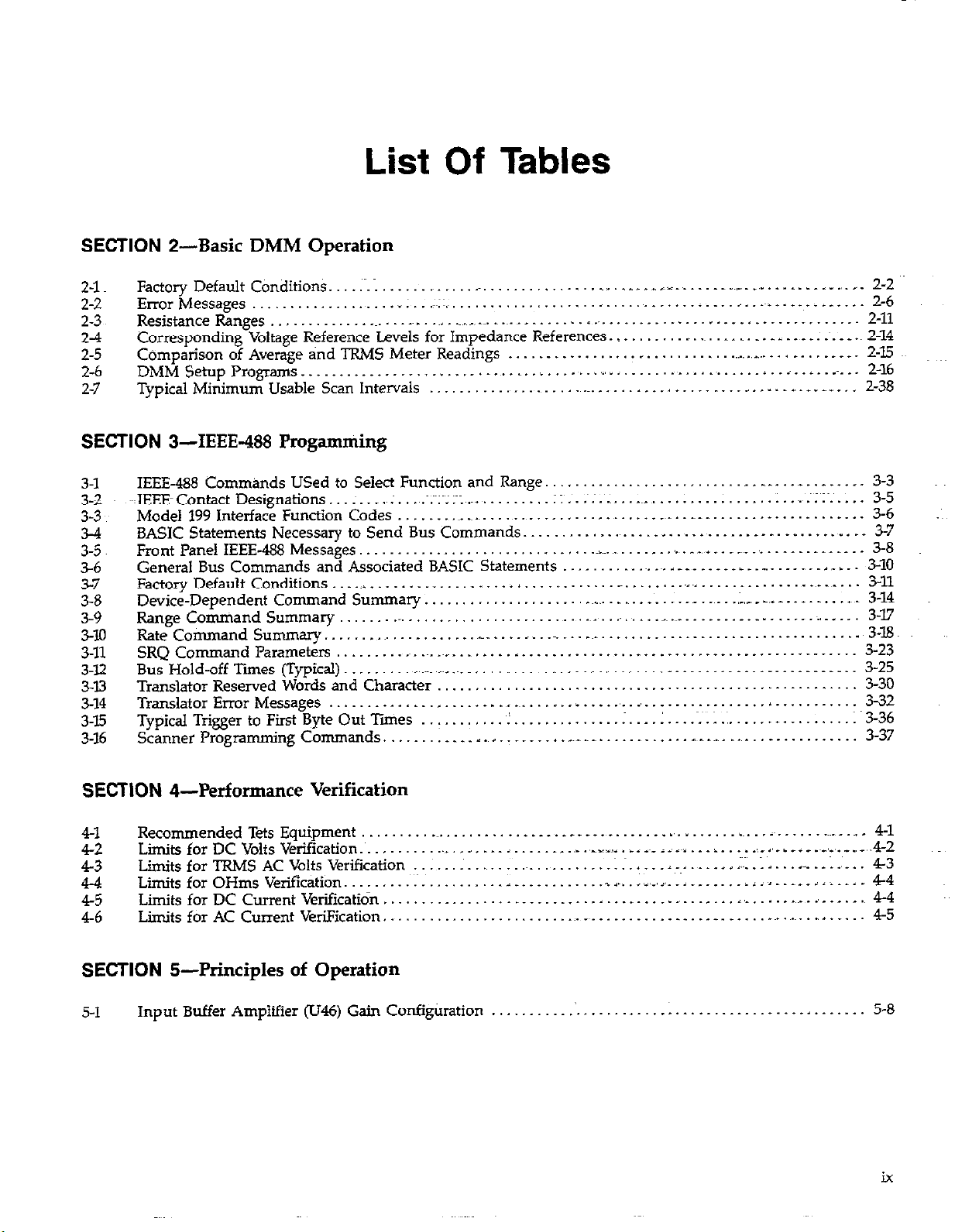
List Of Tables
.~~
SECTION 2-Basic DMM Operation
2-l
2-2
2-3
2-4 Corresponding Voltage Reference Levels for Impedance References.. . ,~. _~. _, . . _. _ _ _ _ _ _ _~. _ _ .~ 2-14
2-5
2-6
2-7
Factory Default Conditions. .~. 1 , _~. . _. _ __ . __:-_ _ _ _ _ _.,__ _._ _ . _ _ _ _ _ _ ., _. 2-2
Error Messages _ : .z.. _ . _ _ _ , ..* _ . . .,. . _ _ _ . 2-6
Resistance Ranges .~_ _~. ~. , _~~,~_, .~. . .~_ . . . . ~ _. . _ . . . . . _ . . _ _ _ _ . 2-11
Comparison of Average and TRMS Meter Readings _ _. _, . .._....... . . _. __ __. 2-15
DMM Setup Programs _ _ _ . . . _ . _ _ _ . ,~. . .~, r ;. _. . _ .~. .~ _ .~_ 2-16
Typical Minimum Usable Scan Intervals .~_ .~.~. . . . . . , _ _ __ .._ . .._.,___ 2-38
SECTION 3-IEEE-488 Progamming
3-l
3-2
3-3
3-4
3-5
56
3-7
3-8
3-9
3-10
3-11
3-Y
3-w
3-14
3-15
3%
IEEE-488 Commknds USed to Select Function and Range. . . , _ . _.. . . _ . . . 3-3
JEEEContact Designations...: . . . . ~; . ~;~:~;::.~ . . . . . . . . :: .~..;..: . . . .._............ . . . ..I . . ~::~ . . . . .
Model 199 Interface Function Codes . . _~_ .~. . . ~. . . . _~_. _ __ _ . . . _ . 3-6
BASIC Statements Necessary to Send Bus Commands. _ . .~. . . . . . _ . _. . . _ . . . .~_. . . 3-7
Front Panel IEEE-488 Messages. . . _~.~~_ ~ ,.~. __, . _. _ __ _.. _ _ _ _ __ __ _ . 3-8
General Bus Commands and Associated BASIC Statements , .,. . . _., , __ _ _ _ _ _ _. _ _. . . . . . , _ . 3-10
FactoryDefaultConditions ____..._._.... .__._..._._ jj ____._......_.._...__ _~ t________....... ~..~ . . . . 3-11
Device-Dependent Command Summary .~_.. _ _ . _ _ _ _ _ .;,. _ _,. _ _ . _ . . _ . .~. 3-14
Range Comniand Summary . _~_ ,. . .,~_~_ _ _ _ __ _ _ _>_. 3-17
Rate Command Summary.. ..~. . _. _.._... .._. ..~ . . . .~.. . _. . . . . . . . 3-li3
SRQ Command Parameters . _~ _~_ .~_, . . . , . _ . . . . . _ _ . _ _ . _ _ _ _ 3-23
Bus Hold-off Times (Typical) . _ _~~_ ~_~L .~. _ , . _ _ _ _ _ _~_ _ _ I . _ _ _ _ . _ . _ _ . _ _ _ . _ _ _ _ _ _ _
Translator Reserved Words and Character . . . . 330
Translator Error Messages . . . _ _ , . _ . .~. .~. . . . . _ . _.. _, . . . . _ . I 3-32
TypicaITriggertoFirstByteOutliies __. . ...,,.. ~1.__...,..__.__ I____ I.... Y;;.:....,. _ ._.__...__ 336
Scanner Programming Commands. _ . _ . I _~ L _ _ _ _ _ . _ .._ _ _ . _ . . . _.. . _, . _ . . _ _
3-5
3-25
3-37
SECTION 4-Performance Verification
4-l
4-2
4-3
4-4
4-5
4-6
Recommended TZ+s Equipment .~, _ _ _ _ _ _ _ _ _ _ _ _ _ . ~ I in. I~ _ _~~_ _ ~. _ 4-1
Liits for DC Volts Verification.~. _. _. _ _ _ , _ _ _ _,. .,_% ,.,.” . _. _~_ iia.l . . . . . .,,. .,_. _i _ _~_,_,. __,_ 4-2
Limits for TRMS AC Volts Verification .~_ .~_ _. _ = _, . . . ,::. .lI.. ,~. . _ .,_. 4-3
LiitsforOHmsVerification _.___.._. _ . . . . . . . . _ ________....SC...~l~ _ ,,,._j___._._ Liil..___l‘L . . . . 44
Limits for DC Current Verificatidn. . . . . . . . . . . . . . . . . . .._. _..,... ~ . . . ,,.. . . . . .._. i_ . . . . . 4-4
Limits for AC Current VeriFication. .~. _~_ _ . . _ _ . . . _. _ . __ ~.~_. _. . _. 4-5
SECTION 5-Principles of Operation
5-l
Input Buffer Ampliiier (U46) Gain Configtiration . .‘. . _ . _ . . _ _ . . . . . . . 5-8
ix
Page 19
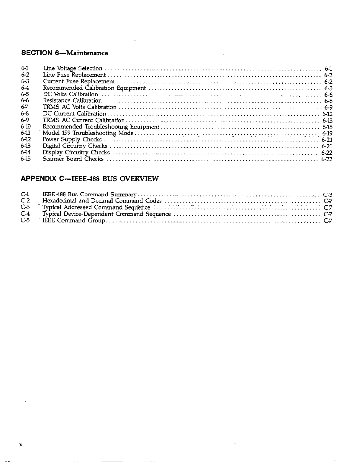
SECTION 6-Maintenance
6-l
6-2
6-3 Current Fuse Replacement .........................................................
6-4
6-5
6-6 Resistance Calibration
6-7 TRMS AC Volts Calibration .....................................................................
6-8
6-9
6-10
6-11
6-12
6-13
6-14 Display Circuitry Checks .........................................................................
645
line Voltage Selection
Line Fuse Replacement ............................................................................
Recommended Calibration Equipment
DC Volts Calibration
DC Current Calibration ............................................................
TRMS AC Current Calibration ..................................................................
Recommended Troubleshooting Equipment
~ModelWTroubIeshootingMode
Power Supply Checks
Digital Circuitry .Checks .......................................................................
ScannerBoard Checks
.............. .
.........................
........................................................
...................
......................
...... _, ..........................................................
.......... :
........................................................
........................
_.~.~ ..... .
.......................................
_~~_~_
.................................
.I .........................................
...
..~................~....................~
APPENDIX C-IEEE-488 BUS OVERVIEW
C-l
c-2
c-3
C-4
c-5
IEEE-488 Bus Command Summary _ _~. . . _1_ C-3
Hexadecimal and Decimal Command Codes _ _ . . . _ . . . . .._ . . ~. .~_
Typical Addressed Command Sequence : .~. : .~.~1. . .,. . .~; .~. _~. _~. ; C-7
Typical Device-Dependent Command Sequence I _~ .~. . . _, . C-7
IEEE Command Group.. . . .~ _~_ .~.~, _. . . . . . . L
,~. ......................
_. ....... _~ ...... ~,-^~.
I ...
,
.......
_
...
, ... , 6-6
. . 6-1.2
.. 6-19
1
.........
L.. I.. ...
I
....
L_.
....... .. ...
......... - .... ~.-~.~
.........
6-l
6-2
6-2
.~,_ 6-3~
1 ~6-8
6-9
6-13
6-18
6-21
6-21
6-22
6-22
C-7
C-7
Page 20
i~fl10N I
General Information
1.1 INTRODUCTION
The Keithley Model 199 System DhJM Scanner is a five
function autoranging digital multimeter. At 5% digit resolu-
tion, the LED display can display &02,999 counts. The
range of this analog-to-digital (A/D) converter is greater
than the normal *199,999-count A/D converter
used in many 5% digit DMMs. The built-in IEEE-488 titerface makes the instrument fully programmable over the
LEEE-488 bus. The Model 199 can make the foBowing basic
measurements:
1. DC voltage measurements from l&V to 3OOV.
2. Resistance measurements from II& to 3OOMR.
3. TRMS AC voltage measurements from 1pV to 309V.
4. DC current measurements from lOOnA to 3A.
5. I’RMS AC current measurements from lOOnA to 3A.
In addition to the above mentioned measurement
capabilities, the Model 199 can make ACT dB voltage and
current measurements.
1.2 FEATURES
l Optional Field-Installable Internal Scanner-Allows the
unit to switch up to 8, 2-pole channels, or 4, 4pole
channels.
1.3 WARRANTY INFORMATION
Warranty information may be found on the inside front
cover of this manual. Should it become necessary to exercise the warranty, contact your KeithIey representative or
the factory to determine the proper course of action.
Keithley Instruments maintains service facilities in the
United States, United Kingdom and throughout Europe.
Information concerning the application, operation or service of your instrument may be directed to the applications
engineer at any of these locations. Check the inside front
cover for addresses.
1.4 MANUAL ADDENDA
Information concerning improvements or changes to the
instrument which occur after the printing of this manual
will be found on an addendum sheet included with the
manual. Be sure to review these changes before attempting to operate or service the instrument.
Some important Model 199 features include:
l 10 Character Alphanumeric Display-Easy to read 14
segment LEDs used for readings and front panel
messages.
l Zero-Used to cancel offsets or establish baselines.
l Data Store-Can store up to 500 readings and is access-
ible over the bus or from the front panel.
l Digital Calibration-The instrument may be digitally
calibrated from either the front panel or over the bus.
l User Programmable Default Conditions-Any instru-
ment measurement configuration can be established as
the power-up default conditions.
l Translator Software-User defined words (stored innon-
volatile memory) can be used to replace standard command strings over the IEEE-493 bus.
1.5 SAFETY SYMBOLS AN6 TERMS
The following safety symbols and terms are used in this
manual or found on the Model 199.
The A
should refer to the operating instructions in this manual.
The&
potential may be present on the terminal(s). Standard safe-
ty practices should be observed when such dangerous
levels are encountered.
The WARNING used in this manual explains dangers that
could result in personal injury or death.
The CAUTION used in this manual explains hazards that
could damage the instrument.
symbol on the instrument denotes that the user
on the mstrument denotes that a hazardous
l-1
Page 21
GENERAL INFORMATION
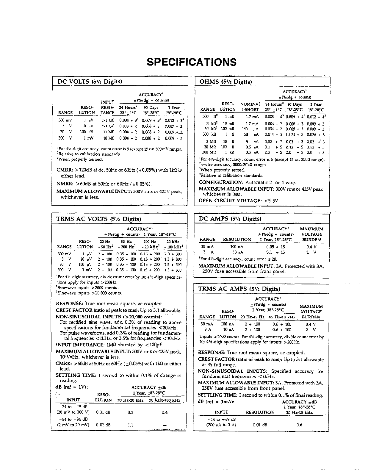
1.6 SPECIFICATIONS
Detailed Model 159 specifications may be found preceding
the Table of Contents of this manual.
1.7 INSPECTION
The Model 199 System DMM was carefully inspected, “th
electricalIy and mechanically before shipment. After Unpacking all items from the shipping carton, check for any
obvious signs of physical damage that may have occurred
during transit. Report any damage to the shipping
agent. Retain and use the original packing materials in case
reshipment is necessary, The following items are shipped
with every Model 159 order:
Model 199 System DMM
Model 199 Instruction Manual
Safety shrouded test leads (Model 1751).
Additional accessories as ordered.
If an additional instruction manual is required, order the
manual package (Keithley Part Number 199-901-00). The
manuai package includes an instruction manual and any~
applicable addenda.
* Section 6 contains information for servicing the instru-
ment. ‘Ihis section includes information on fuse replacement, line voltage selection, calibration and troubleshooting.
l Section 7 contains replaceable pats information.
1.9 GETTING STARTED
The Model 199 System DMM is a highly sophisticated in-
strument with many capabilities. To get the instrument up
and running quickly use the following procedure. For complete information on operating the Model 199 consult the
appropriate section of this manual.
Power up
1. Plug the line cord into the rear panel power jack and
plug the other end of the cord into an appropriate,
grounded power source. See paragraph 22.1 for more
complete information.
2. Press in the POWER switch to apply power to the instrument. The instrument will power up in the 3WV DC
range.
Making Measurements
1.8 USING THE MODEL 199 MANUAL
This manual contains information necessary for operating
and servicing the Model 199 System DMM. The informa-
tion iS divided into the following sections:
l Section 1 contains general information about the Model
199 including that necessary to inspect the instrument
and get it operating as quickly as possible.
l Section 2 contains detailed operating information on
using the front panel controls and programs, making
connections, and basic measuring techniques for each
of the available measuring functions.
l Section 3 contains the information necessary to connect
the Model 199 to the IEEE488 bus and program operating
modes and functions from a controller.
l Section 4 contains performance verification procedures
for the instrument. Thii information will be helpful if
you wish to verify that the instrument is operating in
compliance with its stated specifications.
l Section 5 contains a description of operating theory.
Analog, digital, powei supply, and IEEE-488 interface
operation is included.
1. Connect the supplied safety shrouded test leads to the
front panel VOLTS HI and Lo input terminals. Make
sure the INPUT switch on th-e front panel is in the front
position.
2. To make a voltage measurement, simply connect the in-
~.~rrufleads to a DC voltage source (up to 30OV) and take
ihe reading from the display.
3. To change to a different measuring function, simply
press the desired function button. For example, to
measure resistance, press the OHMS button.
Using DMM Setup
Press SHIFT DMM SETUF, then use NEXT to scroll
through selections. The following can be selected or
viewed:
l Software revision
l MUX on/off
l IEEE-1188 address
l Line frequency
l save setup
l LED test
l Diagnostics
l unit reset
l-2
Page 22
GENERAL INFORMATION
For all selections except software revision and IEEE488 address, use uprangeidownrange to toggle the selection.
Pa’a~;p~~p,provides the detailed information for using
1.10 ACCESSORIES
The~following accessories are available to enhance Mode1
199 capabilities.
Model 1651 SO-Ampere Current Shunt--The Model 1651 is
an external O.oOlQ *l% 4-terminal shunt, which permits
current measurements from 0 to 5OA AC or DC.
Model 1681 Clip-On Test Lead Set-The Model 1681 contains two leads, 1.2m (4 ft.) long terminated with banana
plugs and spring action clip probes.
Model l682A RF Probe-The Model 1682A permits voltage
measurements from 1oOktrz to 25OMH.z. AC to DC t&&r
accuracy is *ldB from 1OOkHz to 25OMHz at IV, peak
responding, calibrated in RMS of a sine wave.
Model 1685 Clamp-On AC Probe-The Model 1685
measures AC current by clamping on to a single conductor. Interruption of the circuit is unnecessary. The Model
1685 detects currents by sensing the changing magnetic
field produced by the current flow.
phone tips (0.06 DIA.), two hooks and miniature alligator
clips (with boots).
Model 1992 4/8 Channel Scanner-The Model 1992 Scan-
ner option allows scanning of four, 4-pole channels, or
eight, 2-pole channels. The Model 1992 installs within the
Model 199 with connections available on the rear panel of
the instrument.
Model 1993 Quick Disconnect Scanner Connector Kit-
The Model 1993 includes two connector blocks, 10 tie
wraps, and two sets of red and black output cables for~the
Model 1992 Scanner Card.
Model 1998 Rack Mounting Kit-The Model 1998-l Single
Fixed Rack Mounting Kit mounts a single Model 199 in a
~~
gandard 19 inch rack. The Model 1998-2 Dual Fied Rack
Mounting Kit mounts two Model 199s side by side in a
standard 19 inch rack.
Model 5806 Kelvin Clip Lead Set-The Model 5806 includes
two Kelvin clip test lead assemblies with banana plug termination (one red, one black). A set of eight replacement
rubber bands for the Model 5806 is also available (Keithley
PIN GA-22).
Model 7007 IEEE-488 Shielded Cables-l-he Model 7007
connects the Model 199 to the IEEE-488 bus using shield-
ed cables to reduce electromagnetic interference @MI). The
Model 7007-1 is one meter in length and has a EMI shielded IEEE-488 connector at each end. The Model 7007-2 is
identical to the Model 7007-1, but is two meters in length.
Model 1751 Safety Test Leads-Finger guards and
shrouded banana plugs help minimize the chance of
making contact with live circuitry.
Model I754 Universal Test Lead Kit-The Model I754 is a
12 piece test lead kit, with interchangeable plug-in accessories. Induded in the kit is one~set Of test leads (l-red,
l-black), two spade lugs, hvo standard banana plugs, two
Model 7008 IEEE488 Cables--The Model 7008 connectsthe
Model 199 to the IEEE-488 bus. The Model 7008-3 is 0.9m
(3 ft.) in length and has a standard IEEE-488 connector at
each end. The Model 7008-6 cable is identical to the Model
7008-3, but is 1.8m (6 ft.) in length.
l-3/1-4
Page 23
SECTION 2
Basic DMM Operation
2.1 INTRODUCTION
Operation of the Model I.99 can be divided into two general
categories: front panel operation and IEEE-188 bus op~ation. This section contains information necessa?y to use
the instrument from the front panel. These functions can
also be programmed over the IEEE-488 bus, as described
in Section 3.
2.2 POWER UP PROCEDURE
2.2.1 Line Power
Use the following procedure to connect the Model 199 to
line power and power up the instrument.
1. Check that the instrument is set to correspond to the
available lie power. When the instrument leaves the
factory, the externally selected line voltage is marked on
the rear panel. Ranges are 105WZ5V or 21OV-25OV
50/6OHz AC (9GllOV, 180~220V with optional transformer). If the line voltage setting of the instrutitint
needs to be changed, set switch as required. If the line
frequency setting of the instrument needs to be checked
and/or changed, utilize front panel DMM SETUP (see
paragraph 2.7) after the instrument completes the power
up sequence (the line frequency is displayed upon
power up).
2. Ctmnect the female end of the power cord to the AC
receptacle on the rear panel of the instrument. Connect
the other end of the cord to a grounded AC outlet.
WARNING
The Model 199 is equipped with a 3-wire power
cord that contains a separate ground wire and
is designed to be used with grounded outlets.
When properconnectiins are made, instrument
chassis is connected to power line ground.
Failure to use a grounded outlet may result in
personal injury or death because of electric
shock.
CAUTION
Be sure that the power line voltage agrees with
the indicated range on the rear panel of the instrument. Failure to observe this precaution
may result in instrument damage.
2.2.2 Power Up Sequence
The instrument can be turned on by pressing in the front
panel POWER switch. The switch will be at the i&w most
position when the instrument is turned on. Upon power
up, the instrument wiIl do a number of tests on itself. Tests
are performed on memory (ROM, RAM and E’PROM). If
RAM or ROM fails, the inshument will lock up. If E*PROM
FAILS,the message “UNCAL” will be displayed. See paragraph 6.7.2 for a complete description of the power up self
test and recommendations to resolve failures.~
Immediately upon power up- the unit will display the programmed line frequency. For example:
FREQ = 60HZ
2.2.3 Default Conditions
Default conditions can be defined as setup conditions that
the instrument will return to when a particular feature or
command is asserted. The Model 199 will return to either
factory default conditions or user saved default conditions.
Factory Default Conditions
At the factory, the Model 199 is set up so that the instrument is configured to certain setup conditions on the initial
power up. These factory default conditions are listed in
Tables 2-l and 3-7 (located in Section 3). If alternate setup
conditions are saved (see User Saved Default Conditions),
the instrument can be returned to the factory default conditions by using Reset, available under DMM SETUP See
paragraph 2.7.
2-l
Page 24
BASIC DMM OPERATION
Table Z-l. Factory Default Conditions
ContmllFeature
Function*
Range*
Resolution*
zero’
dB*
Filter*
Multiplexer*
IEEE-488 Primary Address*
Line Frequency*
Trigger Delay=
Reading Interval*
Trigger Mode*
Data Store
Polest
Ratiot
Scan Modet
5% Digits
Off
off _ ~~=
Offs
On
26
6OHZ
OIlVET Omsec
l75msec (select OffJ l75msec (select OffJ
continuous continuous
Off Off
2
Off
Ma*d I
%ese modes can be altered by using save setup,
tWith optional 1992 scanner.
User Saved Default Conditions
measurement cotiguration that it was set up for (such as
range, zero value, etc). Switchiig back and forth between
functions will not affect the unique configuration of each
function. However, the instrument will “forget” the configurations on power-down unless they are saved (only one
instnnnent configuration can be saved).
Unique setup conditions can be saved by using SAVE
under Dh4M SETUl? or by sending device-dependent command Ll over the IEEE-488 bus. These user saved default
conditions will prevail over the factory default conditions
on power-up, or when a DCL or SDC~is asserted over the
bus.
I
IEEE Address and Line Frequency
Any IEEE address and line frequency setting can be saved
as default conditions by using the SAVE option under
DMM SETUP or by sending Ll over the bus. See paragraph 2.7 for complete tionnation on using DMM SETUP
NOTE
An “UNCAL” error will set the IEEE address to
26 and the line frequency to 60H.z.
Each function of the Model 199 “remembers” the last
Page 25
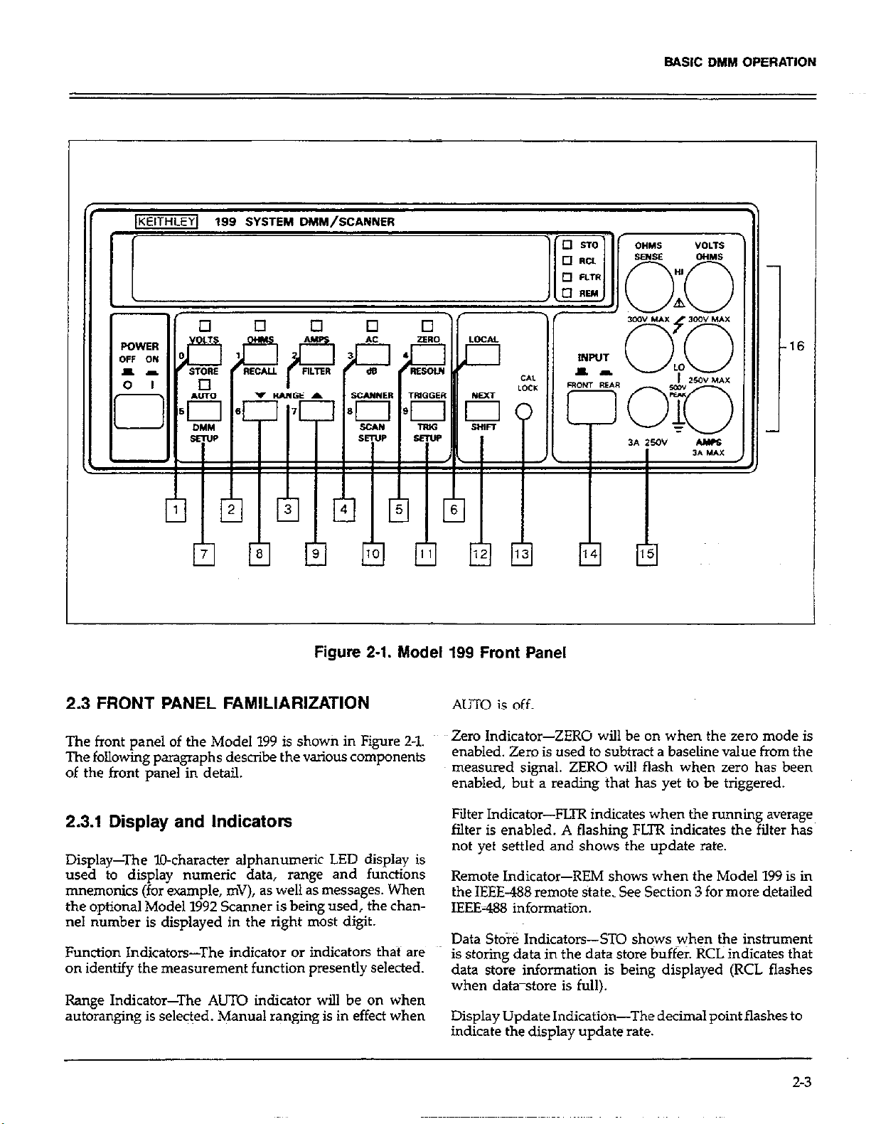
BASIC DHM OPERATION
Figure 2-1. Model 199 Front Panel
2.3 FRONT PANEL FAMILIARIZATION
The front panel of the Model 199 is shown in Figure 2-l.
The following paragraphs describe the vaious components
of the front panel in detail.
2.3.1 Display and Indicators
Display-The l&character alphanumeric LED display is
used to display numeric data, range and functions
mnemonics (for ample, mV), as well as messages. When
the optional Model 1992 Scanner is being used, the channel number is displayed in the right most digit.
Function Indicators-The indicator or indicators that are
on identify the measurement function presently selected.
Range Indicator-The AUTO indicator will be on when
autoranging is selected. Manual ranging is in effect when
AUTO is off.
Zero Indicator-ZERO will be on when the zero mode is
enabled. Zero is used to subtracf a baseline value from the
measured signal. ZERO will flash when zero has been
enabled, but a reading that has yet to be triggered.
Filter Indicator-FIXR indicates when the running average
filter is enabled. A flashing FLTR indicates the filter has
not yet settled and shows the update rate.
Remote Indicator-REM shows when the Model 199 is in
the IEEE-488 remote state. See Section 3 for move detailed
IEEE-488 information.
Data Store Indicators-ST0 shows when the instrument
is storing data in the data store buffer. RCL Indicates that
data store information is being displayed (RCL flashes
when data-store is full).
Display Update Indication-The decimal point flashes to
indicate the display update rate.
2-3
Page 26
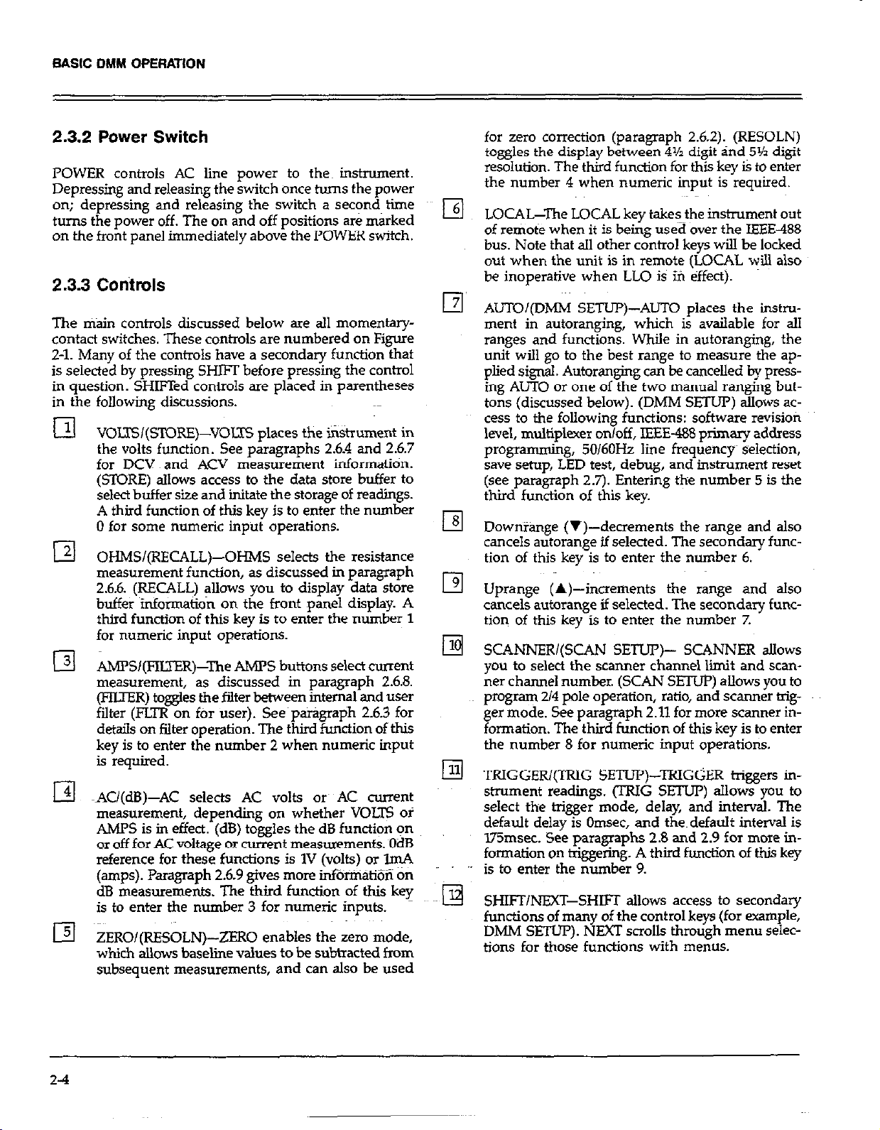
BASIC DMY OPERATION
2.3.2 Power Switch
POWER controls AC line power to then instrument.
Depressing and releasing the switch once turns the power
on; depressing and releasing the switch a sec?nd, time
turns the power off. The on and off positions are marked
on the front panel immediately above the POWER switch.
2.3.3 Controls
The &in controls discussed below are all momentarycontact switches. These controls are numbered on Figure
2-1. Many of the controls have a secondary function that
is selected by pressing SHIFT before pressing the control
in question. SHIFTed controls are placed in parentheses
in the following diiussions.
VOLTSI(STORE)-VOLTS places the ii%.trument in
the volts function. See paragraphs 2.6.4 and 2.6.7
for DCV and ACV measurement informatitin.
(STORE) allows access to the data store buffer to
select buffer size and initate the storage of readings.
A third function of this key is to enter the number
0 for some numeric input operations.
OHMS/(RECALL)-OHMS selects the resistance
measurement function, as discussed in paragraph
2.6.6. (RECALL) allows you to display data store
buffer information on the front panel display. A
third function of this key is to enter the number 1
for numeric input operations.
AMFS/(FImR)-The AMPS buttons select current
measurement, as discussed in paragraph 2.6.8.
(FIIXER) toggles the filter between internal and user
falter (FLTR on ftir user). See paragraph 2.6.3 for
details on filter operation. The third function of this
key is to enter the number 2 when numeric input
is required.
AU(dB)-AC selects AC volts 01~ AC current
measurement, depending on whether VOLE oi
AMPS is in effect. (dB) toggles the dB function on
or off for AC voltage or current measurements. OdB
reference for these functions is 1V (volts) or lmA
(amps). Paragraph 2.6.9 gives more i&%iiiati~~ on
dB measurements. The third function of this key
is to enter the number 3 for numeric inputs.
ZERO/(RESOLN)-ZERO enables the zero mode,
which allows baseline values to be subtracted from
subsequent measurements, and can also be used
for zero correction (paragraph 2.62). (RESOLN)
toggles the display between 4% digit and 5% digit
resolution. The third function for this key is to enter
the number 4 when numeric input is required.
LOCAL-The LOCAL key takesthe instrument out
of remote when it is being used over the IEEE-488
bus. Note that all other control keys will be locked
out when the unit is in remote (LOCAL will also
be inoperative when LLO is ifi effect).
AUTOQDMM SETUP)-ALJTO places the instrument in autoranging, which is available for all
ranges and functions. While in autoranging, the
unit will go to the best range to measure the applied signal. Autoranging can be cancelled by pressing AUTO or one of the two manual ranging buttons (discussed below). (DMM SEl’Ul’) allows access to the following functions: software revision
level, multiplexer on/off, IEEE-488 primary address
programming, 50/60& line frequency~ selection,
save setup, LED test, debug, and instrument reset
(see paragraph 2.7). Entering the number 5 is the
third function of this key.
DownYang= (v)-decrements the range and also
cancels autorange if selected. The secondary function of this key is to enter the number 6.
Uprange (A)-increments the range and also
cancels autorange if selected. The secondary func-
tion of this key is to enter the number 7.
SCANNERI(SCAN SETUP)- SCANNER aJIows
you to select the scanner channel limit and scan-
ner channel number. (SCAN SETUP) allows you to
program 214 pole operation, ratio, and scanner trigger mode. See paragraph 2.11 for more scanner in-
formation. The third function of this key is to enter
the number 8 for numeric input operations.
xxIGGEW(wG SETLJP)-TRIGGER triggers in-
strument readings. (TRIG SETUP) allows you to
select the trigger mode, delay, and interval. The
default delay is Omsec, and the~default interval is
l75msec. See paragraphs 2.8 and 2.9 for more information on triggering. A third function of th& key
is to enter the number 9.
SHIFI/NEXT-SHIFT allows access to secondary
functions of many of the control keys (for example,
DMM SETUP). NMT scrolls through menu selec-
tions for those functions with menus.
2-4
Page 27
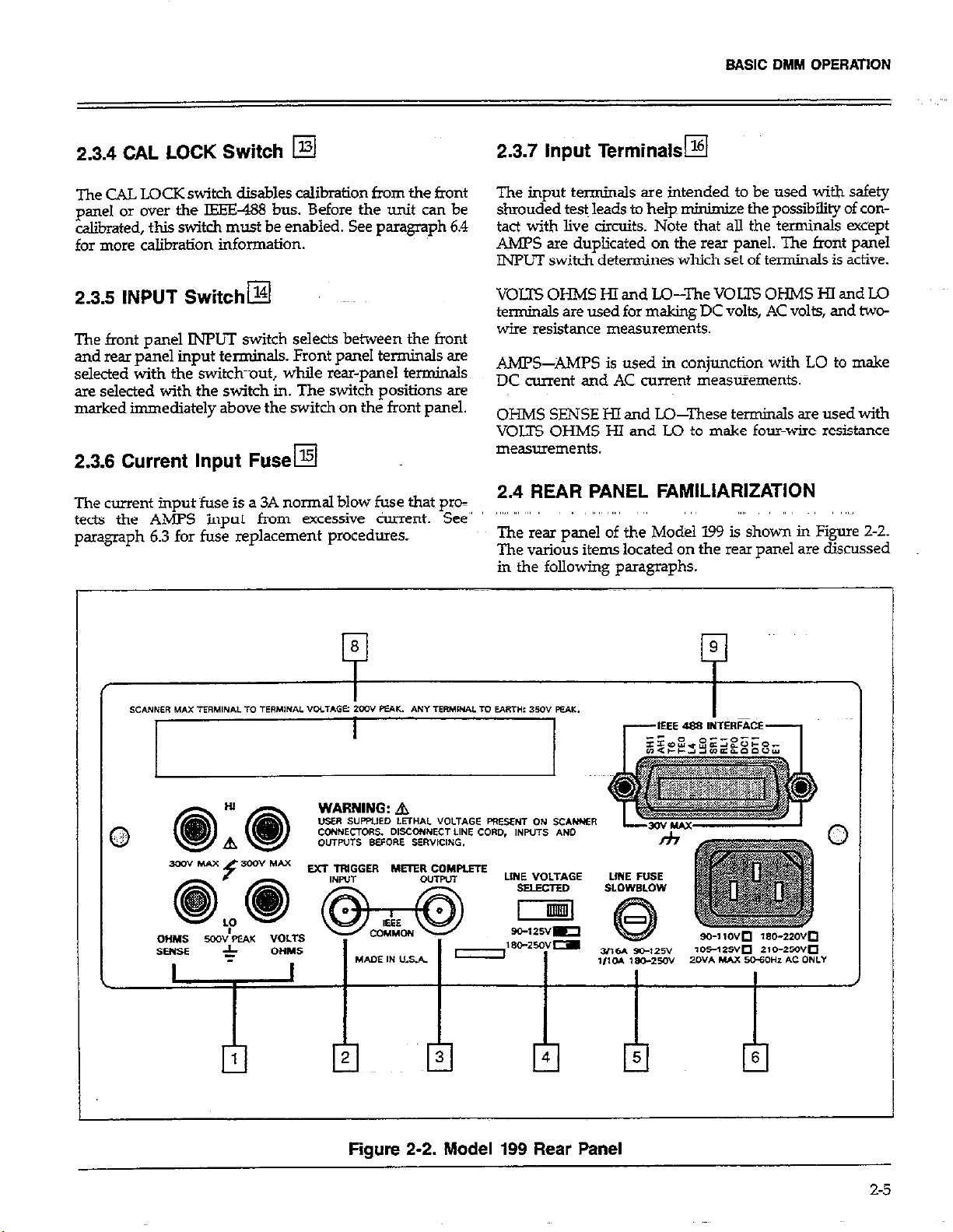
BASIC DMM OPERATION
2.3.4 CAL LOCK Switch q
The CAL LOCK switch disables calibration from the front
paml OI over the IEEE488 bus. Before the unit can be
calibrated, this switch must be enabled. See paragraph 6.4
for more calibration information.
2.3.5 INPUT Switch@
The front panel JNPLTI switch selects between the front
and rear panel input terminals. Front panel terminals are
selected with the switch-aut, while rear-panel term&.&
are selected with the switch in. The switch positions are
marked immediately above the switch on the front panel.
2.3.6 Current Input Fusea
The current input fuse is a 3A normal blow fuse that~ pm=
Theclm . -. . .
t&s the AMPS input from excessive c&rent. See”
tects the AMY> Input rrom excess
paragraph 6.3 for fuse replace~“en+ “7‘
paragraph 6.3 for fuse replacement procedures.
2.3.7 input Terminals~
The input terminals are intended to be used with safety
shrouded te$ leads to help minimize the possibility of contact with live circuits. Note that all the terminals except
AMPS are duplicated on the rear panel. The front panel
INPUT switch determines which set of terminals is active.
VOLTS OHMS HI and LO-The VOJ2-S OHMS HI and LO
terminals are used for making DC volts, AC volts, and twowire resistance measurements.
AMPS-AMPS is used in conjunction with LO to make
DC current and AC current measWements.
OHMS SENSE HI and LO-These terminals are used with
VOLTS OHMS HI and LO to make four-wire resistance
measurements.
2.4 REAR PANEL FAMILIARIZATION
The rear panel of the Model 199 is shown in Figure Z-2.
The various items located on the rear panel are discussed
in the following paragraphs.
Figure 2-2. Model 199 Rear Panel
6
r!l
2-5
Page 28
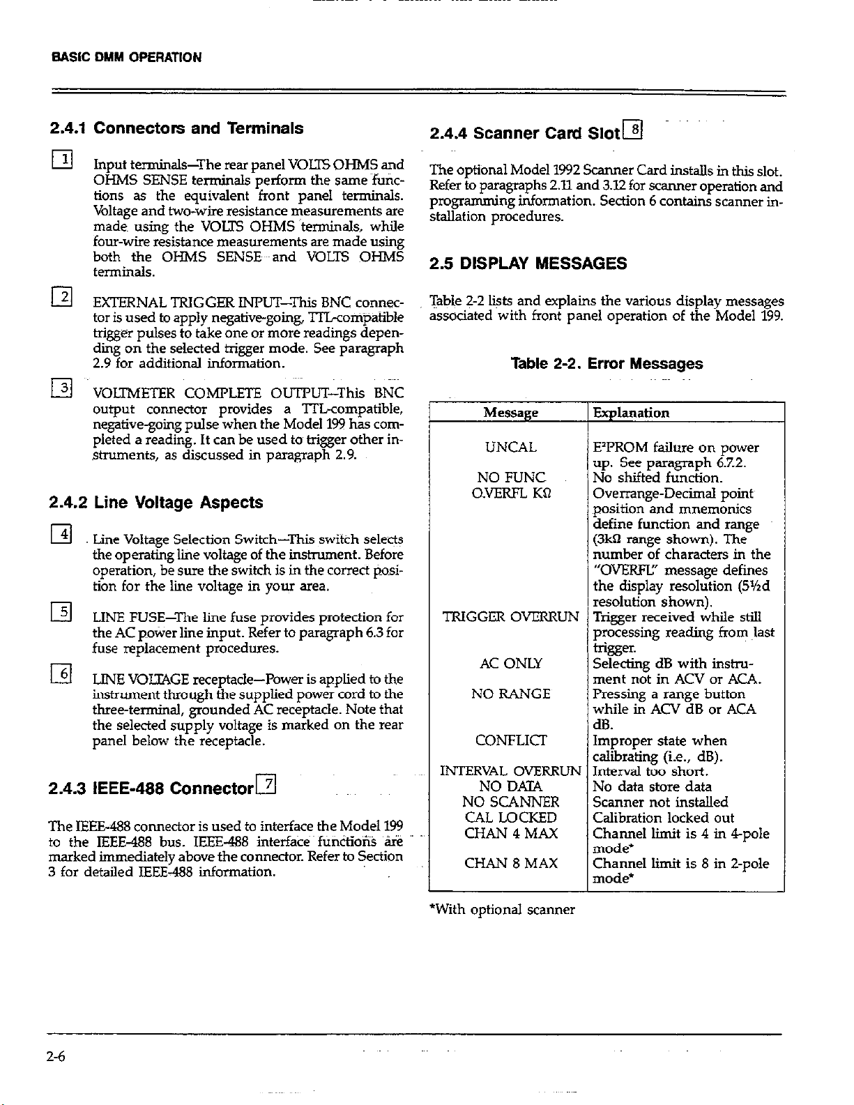
BASIC DMM OPERATION
2.4.1 Connectors and Terminals
El
El
q ~~
Input terminals-The rear panel VOLTS OHMS and
OHMS SENSE terminals perform the same fufic-
tions as the equivalent front panel terminals.
Voltage and two-wire resistance measurements are
made using the VOm OHMS ~terminals, while
four-wire r&stance measurements are made using
both the OI-IMS SENSE eland VOLTS OHMS
termin&.
EXTERNAL TRIGGER INPUT--This BNC connector is used to apply negative-going. TlLconipatible
trigger pulses to take one or more readings dependig on the selected trigger mode. See paragraph
2.9 for additional information.
VOLTMETER COMPLETE OUTPUT-Thii BNC
output connector provides a lTLcompatible,
negative-going pulse when the Model 1% has completed a reading. It can be used to trigger other in-
struments, as discussed in paragraph 2.9.
2.4.2 Line Voltage Aspects
El
El LINE FUSE-The line fuse provides protection for
I3
Lme Voltage Selection Switch-This switch selects
the operating lie voltage of the instrument. Before
operation, be sure the switch is in the correct pOsi-
tion for the lie voltage in your area.
the AC pokier line input. Refer to paragraph 6.3 for
fuse replacement procedures.
LINE VOLZ4GE receptacle-Power is applied to the
instrument through the supplied power cord to the
three-terminal, grounded AC receptacle. Note that
the selected supply voltage is marked on the rear
panel below the receptacle.
2.4.3 IEEE-488 Connector El
The IEEE488 connector is used to interface the Model 199
to the IEEE-488 bus. IEEE-488 interfa& fU&io% ‘s
marked immediately above the connector. Refer to Section
3 for detailed IEEE-488 information.
2.4.4 Scanner Card Sloth
The optional Model 1992 Scanner Card installs in this slot.
Refer to paragraphs 2.11 and 3.12 for scanner operation and
programming information. Section 6 contains scanner installation procedures.
2.5 DISPLAY MESSAGES
Table 2-2 liits and explains the various display messages
associated with front panel operation of the Model 199.
Table 2-2. Error Messages
Message
UNCAL
NO FUNC
O.VERFL KQ
TRIGGER OVERRUN Trigger received while still
AC ONLY Selecting dB with instru-
NO RANGE Pressing a range button
CONFLICT Improper state when
INTERVAL OVERRUN Interval too short.
NO DATA
NO SCANNER
CAL LOCKED
CHAN 4 MAX
CHAN 8 MAX
Explanation
E’PROM failure on power
up. See paragraph 6.7.2.
No shifted function.
Overrange-Decimal pointy
position and mnemonics
define function and range
(3k0 range shown). The
number of characters in the
“OVEKW’ message defines
the display resolution (5%d
resolut~on~shown).
processing reading from last
trigger.
ment not in ACV or ACA.
while in ACV dB or ACA
dB.
calibrating (i.e., dB).
No data store data
Scanner not installed
Calibration locked out
Channel limit is 4 in 4-pole
mode*
Channel limit is 8 in Z-pole
mode*
2-6
*With optional scanner
Page 29
BASIC DMM OPERATION
2.6 BASIC MEASUREMENTS
The following paragraphs describe the basic procedures
for making voltage, resistance, current, and dB measurements.
High Energy Circuit Salty Precauticms
To optimize safety when measuring voltage in high energy
distribution circuits, read and use the directions in the
following warning.
WARNING
Dangerous arcs of an explosive nature in a high
energy circuit can cause severe personal injury
or death. If the meter is connected to a high
energy circuit when set to a current range, low
resistance range or any other low impedance
range, the circuit is virtually shorted. Dangerous
arcing can also result when the meter is set to
a voltage range if the minimum voltage spacing is reduced.
When making measurements in high energy circuits use
test leads that-meet the following requirements:
l Test leads should be fully insulated.
l Only use test leads that can be connected to the circuit
(e.g. alligator clips, spade lugs, etc.) for hands-off
measurements.
l Do not use test leads that decrease voltage spacing. This
diminishes arc protection and creates a hazardous
condition.
CAUTION CAUTION
The maximum common-mode input voltage The maximum common-mode input voltage
(the voltage between input LO and chassis (the voltage between input LO and chassis
ground) is 500V peak. Exceeding this value may ground) is 500V peak. Exceeding this value may
damage the instrument. damage the instrument.
2.6.1 Warm Up Period
The Model 199 is usablq~jmmediately when it is f&t turned
on. Howeve!, the instrument must be aowed to warm up
for at least two hours to achieve rated accuracy.
2.6.2 Zero
The zero feature serves as a means of baseline %uppression by allowing a stored offset value to be subtracted from
subsequent readings. When the ZERO button is pressed,
the instrument takes the currently displayed reading as
a baseline value. All subsequent readings represent the difference between the applied signal level and the stored
baseline.
A baseline level can be established for any or all measurement functions and is remembered by each function. For
Ample, a 1OV baseline can be established on DCV, a 5V
baseline can be established on ACV and a 1OkQ baseline
can be established on OHMS at the same time. These levels
will not be cancelled by switching back and forth between
functions. Once a baseline is established for a measurement function, that stored level wiU be the same regardless
of what range the Model 199 is on. For example, if 1V is
established as the baseline on the 3V range, then the
baseline will also be 1V on the 30V through 3oOV ranges.
A zero baseline level can be as large as full range.
Use the following sequence when testing power circuits:
1.
De-energize the circuit using the regular installed
connect-disconnect device such as the circuit breaker,
main switch, etc.
2.
Attach the test leads to the circuit under test. Use appropriate safety rated leads for thii application.
3.
Set the DMh4 to the proper function and range.
4.
Energize the circuit using the installed connect-
disconnect device and make measurements without
disconnecting the DMM.
5.
De-energize the circuit using the installed connectdisconnect device.
6.
Dkonnect the test leads from the circuit under test.
NOTE
The following discussion on dynamic range is
based on a disolav resolution of 5% dieits. At 41/zd
”
resolution, th’e Lumber of counts would be reduced by a factor of 10.
By design, the dynamic measurement range of the Model
199, at 5%digit resolution, is 606,OKl counts. With zero
disabled, the displayed reading range of the instrument
is GO3,OCHl counts. With zero enabled, the Model 199 has
the capability to display ~606,OCKl c&n-&. This increased
display range ensures that~~the dynamic measurement
range of the instrument is not reduced when using a zero
2-7
Page 30
baseline value. The following two examples will use the
maximum allowable zero values (303,000 counts and
-303,000 cotints) to show that djkamic measurement
range will not be reduced. It is important to note that the
inaased display range does not increase the maximum
allowable input level to the instrument. For example, on
the 3V range, the Model 199 will always over-range when
more than i3.03V is connected to the input.
Example l-The instrument is set to the y DC range+
a maximum -3.03OOOV is established as the zero value.
When -3.03OOCV is connected to the input of the Model
199, the display will read 0.0000W. When +3.03oooV is connected to the inpui, the display will read +6.06OOOV. Thus,
the dynamic measurement range ot the Model~le is OV
to 6.06V, which is 606,000 counts.
for when zeroing the 309Q range with the above procedure.
Baseline Levels--Baseline v&es can be established by ap
plying baseline levels to the instrument. To establish a
baseline level by applying a level to the Model 199, perform the following steps:
1. Disable zero, if presently enabled, by pressing the
ZERO button. The ZERO indicator will turn off.
2. Select a function and range that is appropriate for the
anticipated measurement.
3. Connect the desired baseline level to the input of the
Model 199 and note that level on the display.
4. Press the ZERO button. The display will zero and the
ZERO indicator will be enabled. The previously
displayed reading will be the stored baseline.
Example Z-The instrument is still set to the 3V DC range,
but a maximum +3.03OOOV is the zero level. When
+3.03OCKiV is connected to the input of the Model 199, the
display will read 0.01IO00V. When -3.03OGOV is connected
to the input, the display will read -6.06OOOV. Thus the
dynamic measurement range of the instrument is -6.06V
to OV, which is still 606,000 counts.
Zero Correction-The Model 199 must be properly zeroed
when using the 3COmV DC or~the 3003 range in order to
achieve rated accuracy specifications. This procedure
should be performed whenever the ambient temperature
changes. To use ZERO for zero correction, perform the
following steps:
1. Disable zero, if presently enabled, by pressing fie
ZERO button. The ZERO indicator will turn off.
2. Select the 3OOmV DC or the 30011 range.
3. Connect the test leads to the input of the Model 199
and short them together. If four-wire resistance
measurements are to be made, connect and short all
four leads together. Allow any thermals to stabilize.
Note: At 5Yxiigit resolution, low level measurement
techniques need to be employed. Use Kelvin test leads
or shielded test leads.~See paragraph 2.6.5 for low level
measurement considerations.
4. Press the ZERO button. The display will read zero.
5. Remove the short and connect the test leads to the signal or resistance to be measured.
Note: Test lead resistance (Z-wire) is also compensated
WARNING
With ZERO enabled, a hazardous voltage
baseline level (i4OV or more), not displayed,
may be present on the input terminals. If not
sun? what is applied to the input, assume that
a hazardous voltage is present.
5. Disconnect the stored signal from the input and connect the signal to be measured in its place. Subsequent
readings wiU be the difference between the stored value
and the applied signal.
Notes:
1. Disabling zero cancels the zero baseline value on that
selected fun@ion. Baselines established on other func-
tions are not affected.
2 To store a new baseline on a selected function, zero
must first be disabled and then enabled again. The new
value wiIl be stored with the first triggered conversion.
3. Setting the range lower than the suppressed value will
overrange the display; the instrument ti display the
overflow message under these conditions.
4. When the ZERO button is pressed to enable zero, the
ZERO indicator light will blink until an on scale reading
is available to use as a zero level. In the one-shot trigger mode, the unit must be triggered to store the zero
value.
Page 31

2.6.3 Filter and Resolution
The following paragraphs discuss the internal running
average filter and the 4% and 5% digit resolution modes
of the Model 199.
Filter
The Model 199 uses two running average filters in order
to reduce reading noise. The two filters include the internal filter and the front panel filter, as described below.
When the front panel FLTR light is off, the internal filter
is enabled, and the number of integrations Peru reading
averaged depends on the selected range and function, as
indicated below.
#Integrations
Window
Function Range @3me.s) Per Reading
Averaged
of 1000 counts with 30 readings averaged per reading on
all ranges and functions.
NOTES:
1. In a continuous trigger mode, the FLTR indicator will
flash until the filter is settled. Readings will continue
to update the display while the falter is settling, but the
display will not represent the final, filtered reading value
until FLTR stops flashing (when the proper number of
readings have been averaged).
2. In a one-shot trigger mode, no readings will be
displayed or transmitted over the IEEE-488 bus until the
filter has settled. Each trigger clears the filter, fills the
filter with new readings, and then issues a METER cornplete pulse once the reading is available. Therefore,
ftitered one-shot times can be long.
3. The filter can be turned off entirely by sending the POX
command over the IEEE-488 bus; see paragraph 3.9.
&WllUtiOIl
DCV 3OOmv 6
DCV 3V-3OCv 3 i?
ACV All N0P.e None
Ohms 300%30kQ 4 6
Ohms 3OOkQ 11
Ohms
Ohms
DCA
ACA
dBV
dBA None None
In order to speed up response to large signal steps change,
the Model 199 uses a “window” around the displayed
average. As long as the readings are within this window,
the displayed value is based on the average of the most
recent number of integrations. If a new integratidn is outside this window, the displayed value will be the new
reading, and new averaging will start from this point. The
window value for the internal filter also depends on the
range and function (see above).
The front panel filter is enabled when the front panel FUR
indicator is on. The front panel filter uses a fixed window
3MR ii
30MQ-300MQ 400 ;
All 6
All NOIW None
NlXE None
11
T+ Model 199 can be operated with either 4% or 5% digits
of display resolution. In the 4?&digit mode, the instrument
displays &30,300 counts, while +303,OOO counts are
displayed in the 5%digit mode. Tlw~@ution can be prog&nmed separately for each of the five measuring
functions.
NOTE
On the 3OOkQ and higher resistance ranges, only
5%digit resolution is available.
To change display resolution press SHIFT RESOLN. The
display will toggleto the opposite resolution each time you
perform this keystroke sequence. Note that changing the
resolution restarts the ffiter; the instrumetit will display
dashes after changing resolution until a new reading is
available for display.
The integration period of the AID converter is 2.591~~
in the 4%-d@ mode, while line cycle integration (2Omsec,
50Hz; 16.671&c, 60H.Z) is used ! for 5%digits. Thus the
selected resolution affects the overall reading rate (as does
the selected function and amount of filtering).
2-9
Page 32

2.6.4 DC Voltage Measurements
The Model 199 can be used to make DC voltage measurements in the range of *lpV to +30W.-Use the folIowing
procedures to make DC voltage measurements.
with higher voltages are significant in microvolt signals.
The Model 199 reads only the sipnal received at its inout:
therefore, it is import& that-this signal be prop’erl;
tiansmitted from the source. Se following paragraphs indicate factors which affect accuracy, including thermal ernfs
and stray pick-up.-
CAUTION
The maximum input voltage between the HI and
LO terminals is 42% peak or 300V RMS
whichever is less. Exceeding this value may
cause instrument damage.
1. Select the DC volts function by pressings the VOLTS
hntton
button.
__ - __ -
2. Select a range consistent with the expected voltage or
use autorange.
3. Select the front or rear panel input terminals with the
INPUT switch.
NnTF
._-.-
The 3OOmV DC range requires zero to be-set in
order to achieve rated accuracy. The zero correction procedure can be found in paragraph 26.2.
g. Cofinect the signal to be measured to the selected in-
put terminals as shown in Figure 2-3.
5. Take the reading from the display.
Shielding-AC voltages which are extremely large com- ,tages which are extremely Iage compared with the DC signal may erroneously produce a DC : tne vc‘ signal may erroneously produce a DC
output. Therefore, if there is AC interference, the circuit wefore, if there is AC interference, the circuit
should be shielded with the shield connected to the Model -L’-‘J-J, with the shield connected to the Model
199 input LO (particularly for low-level sources). Improper
shielding can cause the Model 199 to behave in one or more
N ~par&ularly for low-level sources). Improper
sn cause the Model 199 to behave in one or more
of the following ways: wing ways:
1. Unexpected offset voltages. d offset voltages.
2 Inconsistent readings between ranges,
-‘ ----lings between ranges,
3. Sudden shifts in reading. um m reading.
To minimize pick-up, keep the voltage source and the
Model 199 away from strong AC rn@~etic sources. The
voltage induced due to magnetic flux ii proportional to the
area of the loop formed by the input leads. Therefore,
minimize the loop area of the input leads and connect each
Signal at otily one point.
Thermal EMFs-Thermal emfs (thermoelecttic potentials)
are generated by thermal differences between the junction
of dissimilar metals. These can be large compared to the
signal which the Model 199 can measure. Thermal emfs
can cause the following problems:
DC Voltage
source
MODEL 199
Caution :
Maximum Input = 300V RMS, 425V Peak
Input Resistance = 300rnV, 3V ; > lCX2 ; 3OV,llMQ
300V : 1 OMR
. .,-,. .._~~
Figure 2-3. DC Voltage Measurements
2.6.5 Low-Level Measurement Considerations
Accuracy Considerations-For sensitive measurements;
other external considerations besides the Model 199 will
affect the accuracy. Effects not noticeable when working
Z-10
1. Instability or zero offset is much higher than expected.
2. The reading is sensitive to (and responds to)
temperature changes. This effect can be demonstrated
by touching the circuit, by placing a heat source near
the circuit or by a regular pattern of instability (corresponding to heating and air-condition@ systems or
changes in sunlight).~
3. To minimize the drift caused by thermal emfs, use cop-
I
per leads to connect the circuit to the Model 199. A
banana plug is generally suitable and generates just a
few microvolts. ~A clean copper conductor such as #lO
bus wire is about the best for this aonlication. The leads
to the *put may Abe shiclded’ir unshielded, as
” “‘n&essary. Refer to Shielding.
4. Widely varying temperatures-w&ii the circuit can also
create thermal emfs. Therefore, maintain constant
temperatures to minimize these thermal emfs. A cardboard box around the circuit under test also helps by
minimizing air currents.
5. The ZERO control can be used to null out constant offset voltages.
6. Additional thermals may be generated by the optional
Model 1992 Scanner.
Page 33

2.6.6 Resistance Measurements
The Model 199 can make resistance measurements from
lmf? to 300MQ. The Model 199 provides automatic selec-
tion of Z-terminal or 4terminal resistance measurements.
Th% means that if the ohms sense leads are not connected,
the measurement is done 2-terminal. If the sense leads are
connected, the measurement is done 4terminal. For
4-terminal measurements, rated accuracy can be obtained
as long as the maximum lead resistance does not exceed
the values listed in Table 2-3. For best results on the 3WQ.
3k0 and 3OkQ ranges, it is recommended that 4terminal
measurements be made to eliminate errors caused by the
voltage drop across the test leads which will occur when
2-ten&al meazuements are made. The Model 5806
Kelvin Test Lead Set is ideal for low resistance 4termina.l
measurements. In the 4% digit mode, use 4terminsl or
connect the source leads to the sense leads at the instrument to avoid extra noise pickup.
To ~make resistance measurements, proceed as follows:
1. Select the ohms function by pressing the QHMS buttqn.
2. Select a range consistent with the expected resistance
or use autoranee.
3. Select the front or rear panel input termirials using the
J.NruT switch.
4. For 2-terminal measurements connect the resistance to
the instrument as shown in Figure 2-4. For 4terminal
measurements connect the resistance to the instrument
as shown in Figure 2-5.
5. Take the reading from the display.
”
BASIC DMM OPERATION
MODEL 199
----
Figure 2-5. Four-Terminal Resistance
Measurements
Notes:
1. Table 2-3 shows the current output for each resistance
range.
2. It helps to shield resistance greater than 1OOkQ (or
anytime 4% digit resolution is used) to achieve a stable
reading. Place the resistance in a shielded enclosure and
electrically connect the shield to the LO input terminal
of the instrument.
3. Diode Test-The 3kQ range can be used to test diodes
as follows:
A. Select the 3kR range.
8. Forward bias the diode by connecting the red ter-
minal of the Model 199 to the diode anode. A good
diode will typically measure between 3GGQ and IkO.
C. Reverse bias the diode by reversing the c+u-wtions
on the diode. A good diode will overrange the
display.
Shielded
Optional shield
Figure 2-4. Two-Terminal Resistance Measurements
Table 2-3. Resistance Ranges
Maximum Test Lead
S=hd Nominal Resistance (Q) for
Range Resolution I-Short ~1 Count Error (Wzd)
300 0 hnfl 1.7mA 10
3kfl lOmQ 1.7mA 30
30kR lOOmdt
300kR 10 5w 300
3MQ 10 n $A
30MQ 100 n O&A
3ooMO 1 kO 0.5&4 30k
NOTE: Typical open circuit voltage is 5.511
le.4
100
Ik
3k
2-11
Page 34

BASIC DMM OPERATION
2.6.7 TRMS AC Voltage Measurements
The in.Wument can make TFNS AC voltage mez+rements
from 1pV to 3OOV. To m&Wire AC volts, proceed as follows:
1. Select the AC volts function by pressing the VOLTS and
AC buttons.
2. Select a range consistent with the expected voltage or
use autorange.
3. Select the front or rear panel input terminals using the
INPUT switch.
NOTE
There is a small amount of offset (typicaUy 150
counts at 5*/zd) present when using. the ACV
function. Do n&zero this level o&Paragraph
2.610 provides an explanation of AC voltage
offset.
4. Con&a the signal to be measured to the selected input terminals as shown in Figure 2-6.
5. Take the reading from the display.
Clarifications of TRMS ACV Specificatioik
Setiling Time-&c to within 0.1% of change in reading.
This time specification does not include A/D conversion
time.
AC Voltage
SOWX
MODEL 199
Caution :
Maximum input = 300V RMS. 425V Peak, 1 d V. Hz
Input Impedance = 1 MR Shunted by < 1 OOpF
Figure 2-6. TRMS AC Voltage Measurement
2.6.8 Current Measurements (DC or TRMS AC)
The Model 199 can make DC or TRMS AC current
measurements from lOOn.4 (at Wtd resolution) to 3A. Use
the following procedure to make current measurements.
Maximum AIlowable Input-The following graph summa&es the maximum input based on the lOY*Hz
specification.
Maximum Input TRMS AC Volts
Maximum Input TRMS AC Volts
1. Select the DC current or AC -nt ‘Kiticfion by prrssing
the AMPS button (also press AC for AC current).
2. Select a range consistent with the expected current or
use autorange.
3. Connect the signal to be measured to the front-panel
input terminals as shown in Figure 2-7.
4. Take the reading from the display.
MODEL 199
Caution ; Maximum Continuous input = 3A
Front Panel
Figure 2-7. Current Measurements
2-12
Page 35

BASIC DMM OPERATION
2.6.9 dB Measurements
The dB measurement mode makes it possible to compress
a large range of measurements into a much smaller scope.
AC dB measurements can be made with the instrument
in the ACV or AC4 function. The relationship between dB
and voltage and current, can be expressed by the follow
ing equations:
In ACV, the instrument will read OdB when 1V is applied
to the input. With ACA dB selected, the instrument will
read OdB when ImA is applied to the input.
Reference levels other than 1V and l.mA cannot be directly
programmed, but they can be established with the zero
feature. This procedure simply consists of applying a signal
to the instrument and pressing the ZERO buttonThat
suppressed level is the dB reference (OdB point).
5-tenable the dB measurement mode by pressing SHIFT
dB.
6. Take the dB reading from the display.
WARNING
With dB enabled, a hazardous voltage baseline
level (34OV or more), not displayed, may be present on the input terminals. If not sure what is
applied to the input, assume that a hazardous
voltage is present.
dBm Measurements-dBm is defined as decibels above or
below a lmW reference. dB measurements can be made
in terms of impedance rather than voltage or current.
Because the instrument cannot directly establish impedance references, a voltage reference must be calculated
and established for a particular impedance reference. Use
the following equation to calculate the voltage reference
needed for a particular impedance reference:
Example: Calculate the voltage reference needed to make
dBm measurements referenced to 6000.
The following procedure explains how to use the zero
feature to establish a reference:
1. Apply a voltage or current signal, that is to~@used as
the dB reference, to the input of the Model 199.
2. Press the ZERO button. The ZERO indicator will turn
on and the display will zero. The reference is now
whatever the applied signal is.
3. Disconnect the signal from the instrument.
AC dB Measurements-Perform the following steps to
make dB measurements:
1. Select the AC volts or AC amps function. (Press,VOlX
or AMPS, then AC).
2. Select the front or rear panel input terminals with the
INPUT switch.
3. Check and/or change the dB reference as previously
explained.
4. Connect the signal to be measured to the .tiput of the
Model 199.
For OdBm, V,., = ~O.oOlW l 6OOQ
= -iiF
= 77456V
Once the necessary voltage reference is known, it~~can be
established in the Model 199 with the dB program. Subse-
quent dBm readings will be referenced to the correspond-
ing impedance reference. Table 2-4 lists the voltage
references needed for some commonly used impedance
references.
dBW Measurements-dBW is defined as decibels above or
below a 1W reference. dBW measurements are made in the
same manner as dBm measurements; that is, calculate the
voltage reference for a particular impedance and set the
instrument to it with the dB program. The only difference
between dBm and dBW is the reference point; lmW vs 1W.
The following equation can be used to calculate the voltage
reference:
For OdBW, V,., = K
24.3
Page 36

BASIC DMM OPERATION
Table 2-4. Corresponding Voltage Reference Levels
for Impedance References
Reference
Impedance
W)
8
50
75
150
300
600
lml
I
V,, for OdBm = q 10~‘W*Z,,
V,, for OdBW = 4 Z.,
Reference Voltage
Level for:
OdBm ’ OdBW
0.0894 2.828
0.2236
0.2739
0.3873
0.5477
0.7746
1.0000
I
I.
2.6.10 TRMS Considerations
Most DMMs actually measure the average value of an input waveform but are calibrated to read its RMS equivalent.
This poses no problems as long as the waveform being
measured is a pure, low-distortion sine wave. For complex,
nonsinusodial waveforms, however, measurements made
with an averaging type meter can be grossly inaccurate.
Because of its TRMS measuring capabilities, the Model 199
provides accurate AC measurements for a wide variety of
AC input waveforms.
wave with a peak amplitude of NV. The average value of
the voltage is 6.37V while its RMS value is 7UV. If we apply the 1.11 correction factor to the average reading, it can
be seen that both meters will give the same reading,
resulting is no error in the average-type meter reading.
The situation changes with the half-wave rectified sine
wave. As before, the peak value of the waveform is lOV,
but the average value drops to 3.18V. The KMS value of
this waveform is 3&V, but the average responding meter
will give a reading of 3.53V (3.18 x 1X), creating an error
of 11%.
A similar situation exists for the rectified square wave,
which has an average value of 5V and an F&IS value of
5.OV. The average responding meter gives a TRMS reading
of 5.55V (5 x Ill), while the Model 199 gives a TRMS
reading of 5V. Other waveform comparisons can be found
in Table 2-5.
AC Voltage Offset-The Model 199, at 5&d resolution, will
typically display 150 counts of offset on AC volts with the
input shorted. This offset is caused by the offset of the
TENS converter. This offset will not affect reading accuracy
and should not be zeroed out using the zero feature. The
following equation expresses how this offset (V+,) is add-
ed to the signal input (V,.):~
TRMS Measurement Comparison-The RMS value of a
pure sine wave is equal to 0.707 times its peak value. The
average value of such a waveform is 0.637 times the peak
value. Thus, for an average-responding meter, a correction
factor must be designed in. This correction factor, K can
be found by dividing the RMS valued by the average value
as follows:
K = OX7 / 0.637
= 1.11
By applying this correction factor to an averaged reading,
a typical meter can be designed to gives the RMS
equivalent. This works fme as long as the waveform is a
pure sine, but the ratios between the RMS and average
values of different waveforms is far from constant, and can
vary considerably.
Table 2-5 shows a comparison of common types of waveforms. For reference, the first waveform is an ordinary sine
Example: Range = 2VAC
Offset = 150 counts (1.5mV)
Input = 2COmV RMS
Display reading = -V)’ +~ (l.Smv)>
= J 0.04v + (2.25 x 10%)
= .200005V
The offset is seen as the last digit which is not-displayed.
Therefore, the offset is negligible. If the zero feature were
used~ to zero the display, the 150 counts of offset would
be subtracted from Vi. resulting in an error of I50 counts
in the displayed reading.
Crest Factor-The crest factor of a waveform is the ratio of
itspeak value to its RMS value. Thus, the crest factor
specifies the dynamic range of a TRMS instrument. For
sinusoidal waveforms, the crest factor is 1.414. For a symmetrical square wave, the crest factor is unity.
2-14
Page 37

ElASlC DMM OPERATION
The aest factor of other wavefoms will, of course, depend
on the waveform in question because the ratio of peak to
RMS value will vary Fbr -pie, the crest factor of a pulse
is computed as follows:
Table 2-5. Comparison of Average and TRMS Meter Readings
AC
Coupled
Peak RMS
Waveform
%lle
Half-Wave Rectified Sine
?ull-Wave Rectified Sine
+,O--
0
47
+:m
V&E
lov
lov
1ov
Vah
ZON
3.86V
3.08V 2.98v 3.08V 3.2%
Where T = period
t = pulse width
This relationship holds for all pulse waveforms.
AVerage AC Coupled
Responding
Meter
Reading
7.07v
3.9ov
TRMS M&r
M&T Percent
Reading
zO7V 0%
3.86V 1%
Averaging
Error
+:m
>quare
+10- -
0
%-
Rectified Square Wave
‘7-
&tangular Pulse lov 10. JK 22x
+10--
iiangular Sawtooth XIV
x
o Y
4?fP
-
D.W
K.D.D’
lov 1o.oov
XIV
5.OOV 5.55v 5.Oov
5.77v
11.10v
5.55v 5.77v 4%
1o.ooV 11%
lO’Jk----
[ 2.y”‘-K] xl00
11%
Page 38

2.6.11 dB Applications
2.7 DMM SETUP PROGRAMS
Measuring Circuit Gain/Loss-Any point in a circuit can
be established as the OdB point. Measurements in that cir-
cuit are then referenced to that point expressed in terms
of gain (+dB) or loss (-dB). To set the zero dB point pm-
teed as follows:
1. Place the Model 199 in AC volts and dB.
2. Connect the Model 199 to the desired location in the
circuit.
3. Press the ZERO button. The display will read OdB.
4. Gainlloss measurements can now be made referenced
to the OdB point.
Measuring Bandwidth-The Model 199 can be used to
determine the bandwidth of an amplifier as follows:
1. Connect a signal generator and a frequency counter to
the input of the amplifier.
2. Set the Model 199 to AC v&s and autorange.
3. Connect the Model 199 to the load of the amplifier.
4. Adjust the frequency of the signal generat& until ape+
AC voltage reading is measured on the Model 199. This
is the center frequency.
5. Press SHIFT dB button and then press the ZERO button. The OdB point is now established.
6. Increase the frequency input until the Model 199 reads
-3.OOdB. The frequency measured on the frequency
counter is the high-end limit of the bandwidth.
7. Decrease the frequency input until the dB reading again
falls to -3.OOdB. The frequency measured on the signal
generator is the low-end limit of the bandwidth.
There are eight DMM setup programs available from the
front panel of the Model 199, as summarized in Table 2-6.
These programs are described in detail in the following
paragraphs.
Program Selection-Programs can be selected by pressing
SHIFT DMM SETUP on the front panel. To scroll through
programs, press the NEXT key. Once the desired program
is displayed, perform the necessary operation, as described
below.
Data Entry-The IEEE-488 primary address program requires numeric data entry. To enter data, use the data entry keys (O-9). The cursor location for data entry is indicated
by the bright, flashing display digit. The cursor moves right
each time a number is entered. The cursor will wrap
around to the left after exiting the right most digit. When
the desired value is displayed, press SHIFf to program
the value.
Alternate Condition Selection-Most DMM setup pro-
grams have a&mate conditions that can be selected. TO
toggle the conditiop, press uprange or dowmange to alter-
nate between the the two selections.
Exiting DMM Setup-To exit DMM setups, repeatedly
press NEXT and scroll through the complete list in the
UlH-l”.
Table 2-6. DMM Setup Programs
Note: The bandwidth of the Model 199 is typically
3CKlkHz. Do not use this application to check amplifiers
that exceed the bandwidth of the Model 199.
Determining Q-The Q of a tuned circuit can be determined as follows:
1. Determine the center frequency and bandwidth as explained in the previous application (Measuring
Bandwidth).
2. Calculate Q by using the following formula:
Q = Center Frequency/Bandwidth
2-16
Display Message
/ Program Description
Software revision level
Multiplexer on/off
IEEE Primary Address
Line frequency (50 or 6OHz)
Save instrumerit setups
Reset instrument
*Factory default values shown. 6Oti is default in the U.S.
O=lY
“Revision level may vary.
upon Entry
REV.A0.66+’
MUX ON
26 IEEE*
FREQ=6OHz’
SAVE NO
LEDS OFF
DEBUG OFF
RESET NO
J
Page 39

BASIC DMM OPERATION
2.7.1 Software Revision Level
Upon entry to the DMM setup programs, the instrument
will briefly display the software revision level presently installed in the unit, as in the example below:
REV.AO.66
2.7.2 Multiplexer, Auto Zero/Cal
The multiplexer auto/cal routines may be defeated by selecting this option under DMM setups. Using the Model 199
with auto zeroical defeated has two main advantages: (1)
increased measurement speed, and (2) reduced multiplexer effects bn high-impedance measurements.
NOTE
With the multiplexer disabled, internal calibration
and zero are affected by changes in input level,
uarticularlv on ohms and the 300V range.
tVheneverihe applied input signal changes, press
the selected function button to perform ati auto
zeroical routine; otherwise, substantial measurement errors will result. Zero and calibration may
also drift with time; thus, it is recommended that
the selected function button be pressed periodica-
ly to attain optimum accuracy while auto +ero
is disabled (multiplexer off). An auto zeroical is
performed whenever the range or function is
changed.
NFXT to scroll to the next program and save current
multiplexer status.
2.7.3 IEEE-488 Primary Address Programming
The IEEE-488 primary address program allows you check
or modify the IEEE-488 primary address of the instrument.
The factory default primary address is 26, but it can be pro-
grammed to any valid value between 0 and 30 as outlined
below. Section 3 contains detailed information on IEEE-488
programming.
Perform the following steps to use this program,
1. Press SHIFT DMM SETUP and then NEXT repeatedly
until the following message is displayed:
26 IEEE
Here we have assumed the factory default primary address
of 26.
2. ~To exit the progmm without changing the address, press
NEXT
3. To change the address, key in the desired digits~in the
range of 030, and press NEXT to go on to the following
program.
Run this program as follows:
1. Press DMM SETUP and then NEXT as ~required until
the following message is displayed:
MUX ON
2. Use uprange or downrange to select multiplexer on/off,
as required. For multiplexer off, the instrument will
display:
MUX OFF
3. Once the desired multiplexer status is displayed, press
NOTES:
1. If an invalid address is entered, the primary address will
be set to 30 upon exiting the program.
2. To change the default address of the instrument, fist
set the address to the desired value, and then use the
save setup program (or send Ll over the bus). Cycling
power, or sending SDC, DCL, or LO over the bus will
not affect the newly-saved default~primary address.
3 If the IEEE-488 primary address is changed but not
saved, cycling power will return the instrument to the
original default address. However, program reset, or
DCL or SDC commands will not affect the current ad-
dress. Sending LII over the bus will not change the current address, but it will change the default address to
the new value.
4 An “LJNCAL” error will default the address to 26 and
the line frequency setting to 60Hz.
2-w
Page 40

BASIC DMM OPERATION
2.7.4 Line Frequency
The programmed line frequency should match that of the
power line voltage in order for the instrume~nt to meet its
noise specifications at 5%-d@ resolution (line cycle in-
tegration is used at~S%-digit resolution). The line frequency
program can be used to check the programmed line frequency and set it to 50 or 60Hz.
Proceed as follows in order to check or set the line
frequency:
1. Press SHIFI DMM SETUP and then NEXT repeatedly
until the line frequency message is displayed. For 6OHz,
the display will show:
FREQ=60Hz
2. For 50Hz, the display message is:
FREQ=50Hz
3. Use uprange or downrange to toggle to the desired @e-
quency, then press_NEXT to go on to the next program.
NOTES:
1. To change the default frequency setting, ftist select the
desired frequency and then use the save setup program
(or send Ll over the bus) to save the new frequency setting. Cycling power, or sending SDC, DCL, or L1, over
the bus will not affect the programmed line frequency.
2. Jf the line frequency is changed but not saved with the
save setup progmm, sending SDC or DCL over the bus
will return the line frequency to the default setting.
However, the reset program will not have any effect orI
the current frequency setting, and sending LO over the
bus will not change the setting, but will save the new
frequency.
3. An “UNCAL!’ error will default the IEEE-488 primary
address to 26 and set the line frequency to 6OHz.
2.7.5 Save Setup
The save setup program allows you to save current instrument conditions. These conditions will then be assumed
upon power up, or after the instrument receives the DCL
or SDC command over the IEEE-488 bus.
The following operating parameters are saved by this
program:
Function
Range
Resolution
Zero state (on/off)
Filter state (on/off)
AC dB state (onioffl
Multiplexer (on/off)
Trigger delay
Reading interval
IEEE488 primary address
Line frequency (50 or 60Hz)
In order to save an instrument setup, proceed as follows:
1. Setup instrument operating conditions as desired, or use
the reset program (paragraph 2.78) to save default
operating conditions.
2. Press SHIFT DMM SETUP and then NEXT until the
following message appears:
SAVE NO
3. Use uprange or downrange to toggle to the following
message:
SAVES YES
4. To’save instrument setup conditions, press NEXT. The
unit will save the op~erating states and then go on to the
next program.
NOTES:
l.To exit the program without changing the previous
default conditions, press NEXT with the “SAVE NO”
message displayed.
2. To return the instrument to the factory power up default
conditions, use the reset program and then save those
conditions using the save setup program.
Page 41

BASIC DMM OPERATION
2.7.6 LED lest
This program allows you to test all the front panel annunciators and LED display segments to check for proper
operation. Proceed as follows:
1. Press DMM S!CTUP and then NEXT repeatedly until the
following message is displayed:
LEDS OFF
2. To test the LEDs, use uprange or downrange to toggle
the display to the following:
LEDS ON
3. Press NEXT to initiate the test.
4. During the test, the instrument will turn on all the annunciators and walk through the various display
segments and complete displays to verify that ally are.
operating properly. Following the test, the instrument
will scroll to the next program.
2.7.7 Debug
The debug program is intended to switch various LED%
relays, and logic levels to allow signal tracing through the
instrument duing troubleshooting. Also, memory tests are
performed. For complete details on using the debug, refer
to paragraph 6.7.3.
To exit the diagnostic program, press any key except
TRIGGER.
2.7.8 Reset
The reset program restores iristrument setup parameters
to the factory default conditions listed in ‘Tables 2-l and 3-7
3. Press NEXT to reset the instrument, which will return
to the default conditions listed in Table 2-1.
NOTES~:
1. The reset program can be aborted by pressing NEXT
with the ‘XESET NO” message displayed.
2. Once the instrument has been reset to default conditions, use save setup to save that configuration if you
desire that the instrument power up in those conditions.
3. The reset program has no effect on the programmed
IEE~l%488 primary address or line frequency setting.
2.8 FRONT PANEL TRIGGERING
The following paragraphs discuss front panel triggering,
trigger mode selection, as well as trigger delay acd reading
interval programming.
2.8.1 Trigger Mode Selection
The Model 199 may be operated in two basic trigger modes:
one-shot and continuous. In the one-shot mode, a separate
trigger is required to initiate each reading. For the con-
tinuous mode, however, only a single trigger is required,
with the conversion rate determined by the programmed
reading interval. The continuous trigger mode is the fac-
tory default.
To check or change the selected trigger mode, proceed as
follows.
1. Press SHIFT TRIG SETUP. The instrument will display
the presently selected trigger mode. For the continuous
mode, the display will show:
coNTINuous
2. For the one-shot mode, the display reads:
Perform the following steps to use this program.
1. Press SHIFT DMM SETUP and then NEXT repeatedly
until the following message is displayed:
RESET NO
2.&e uprange or downrange to toggle the display as
follows:
RESFT YES
O~NE SHOT
3. TCtij@e the trigger mode, press uprange or dowruange.
4. Once the desired trigger mode is displayed, press NEXT
to scroll to the next menu selection (trigger delay), or
press NEXT to relurn to normal fronts panel display.
2-19
Page 42

2.8.2 Trigger Sources
For standard bench operation, there are two trigger sources
available: front panel TRIGGER button, and the EXTERNAL TRIGGER INPUT jack. Upon power up both these
trigger sources will be enabled. Additional triggers include
IEEE-488 X, GET, and talk commands, as discussed in
paragraph 3.9.7.
NOTES:
1. TRIGGER is always enabled regardless of the selected
trigger source; however, all front panel buttons will be
locked out when the unit is in remote.
2.~ Triggering the unit while it is still processing a reading
from a previous trigger will generate the “TRIGGER
OVERRUN” message.
2.8.3 Trigger Delay
between individual readings when the instrument is in the
continuous trigger mode. Interval also affects the rate of
data store operation, as discussed in paragraph 2.10, as well
as the interval between channels (step mode) or scan sequences (scan mode) when using the optional Model 1992
Scanner (see paragraph 2.11).
The unit can beprogrammed for either default or selected
interval operation. With default interval (“SELECT OFF’!),
a preset interval of l7Smsec is automatically selected. With
selected interval (“SELECT ON”) a user-defined interval
can be programmed. The allowable range for selected interval is l5msec to 999.999sec in lmsec increments.
NOTE
Programming too short an interval for the present
instrument configuratiozi when using the scanner
or data store will result in the “INTERVAL OVERRUN” message. The interval cannot be programmed if the unit is in the one-shot trigger mode.
The trigger delay period is the time from the trigger point
until the unit takes a reading. This delay period is also used
after each channel closure when using the scanner. For the
continuous mode, the delay period affects only the fast
conversion; however, with the one-shot mode, the delay
period affects every conversion, with the instrument
waiting the programmed delay time after each tr&ger
before taking a reading. For example, if you program a
300msec trigger delay, the unit will wait 3i%msec after each
trigger before taking a reading.
The allowable range for the trigger delay peliod is between
0 and 999.999 seconds in one millisecond increments. The
trigger delay can be programmed with the TRIG SETUP
key, as described below.
1. Press SHIFT TRIG SETUP and then NEXTand note the
following message is displayed briefly:
DELAY=
000.000s
Here, we have assumed the factory default delay period
of Osec.
2. Using the the data entry keys (O-9), key in the d#red
trigger delay period in the range of O-9999YYsec.
3. Once the desired delay value is programmed, press
NEXT to go on to the interval selection (or press NEXT
once more to return to normal display).
2.8.4 Reading Interval
Reading interval can be checked or programmed with the
TRIG SETUP key, as follows.
1. Press SHTn TRIG SETUP and then NEXT repeatedly
until the following is displayed:
INTERVAL
Next, the unit displays:
SELECT OFF
Or;~
SELECT ON
2. Use uprange or downrange to select th-e-desired interval type, select or default, then press NEXT. If default
(SELEa OFF) is selected, the interval will be set to
l75msec, and the unit Will return to normal display.
3. If select interval is chosen, the presently selected interval will then be displayed, as in this example:
INTERVAL =
ooo.l.75 s
Here we have assumed the default interval of l75msec.
4. If desired, key in a new reading interval fin the range
of 15msec to Y99.999seC.
5. Once the desired interval is displayed, press NEXT to
return to normal display. If you progam too small =*
interval, the following will be displayed:
The reading interval parameter determines the time period
2-20
MIN = .OlS S
Page 43

BASIC OYM OPERATION
2.8.5 Trigger Programming Examples
Example 1: Continuous with 3.5s~ intervals, between
readings.
1. Press SHIFi’ TRIG S.ETUP and then uprange or downrange (if necessary) so the unit displays the following:
coNTINuous
2. Press NEXT twice to advance to the interval display
message.
3. Use uprange or downrange to choose select interval
(“SELECT ON”), if necessary, then press NEXL
4. Press: 0 0 3 5 0 0 in order to program a 3.5s~ interval.
5. Press NEXT to return to normal display.
6. Connect a time-varying signal to the instrument, and
select a function and range suitable for the applied
signal
7. Press TRIGGER to initiate readings. Note that the
display updates at a rate of once every 3% seconds, as
shown by the following decimal point.
Example 2: One-shot trigger mode with a one second higger delay.
trigger other devices.
2.9.1 External liigger
The external trigger input requires a falling edge pulse at
TTL logic levels, as shown in Figure 2-8. Connections to
the rear panel EXTERNAL TRIGGER INPUT jack should
be made w~ith a standard BNC connector. If the instrument
is in the external trigger mode, it will be triggered to take
readings while in either a continuous or one-shot mode
when the negative-going edge of the external trigger pulse
CICCUIS.
,.
Triggers on
r(- Edgi
1. Press SHJFI TRIG SETUP and then uprange or
downrange (if necessary) so the unit displays the
following:
ONE SHOT
2. Press NEXT to advance to the delay time selection.
3. Press: 0 0 1 0 0 0 to program a one second delay.
4. Press NEXT to return to normal display.
5. Connect a time-varying signal, and select an appropriate
range and function.
6. Press TRIGGER to initiate a single reading. Note that
the display updates once after a delay of approximately
one second.
7. Press TRIGGER a number of times, and note that one
reading per trigger is processed with a one second interval between triggers and readings. The trigger~status
LED (flashing decimal point) indicates the display
update.
2.9 EXTERNAL TRIGGERING
The Model 199 has two external BNC connectors on the
rear panel associated with instrument triggering. The EXTERNAL TRIGGER INPUT connector allows the instrument to be triggered by other devices, while the METER
COMPLETES OUTPUT connector allows the instrument to
Figure 2-8. External Trigger Pulse Specifications
To use the external trigger, proceed as follows:
1. Connect the external trigger source to the rear panel
BNC EXTERNAL TRIGGER INPUT connector. The
shield (outer) part of the connector is connected to
digital com.mon. Since an internal pull-up resistor is used, a mechanical switch may be connected across the
jack contacts. Note however, that debouncing circuitry
will probably be required to avoid a trigger overrun.
WARNING
Do not exceed 3llV between digital common and
chassis ground, to avoid a shock hazard and
possible instrument damage.
2. Place the instrument in “one-shot on external trigger”
or “continuous on external trigger” mode as explained
in paragraph 2.8.1.
3. To trigger the instrument, apply a pulse to the external
trigger input. The instrument will process a single
reading each time the pulse is applied (one-shot), or
start a continuous series of readings.
2-21
Page 44

BASIC DMM OPERATION
NOTE 2.10 DATA STORE
Triggering the unit while it is processing a reading
from a previous trigger will cause a ‘TRIGGER
ow3Ruw.
2.9.2 Meter Complete
Data Store cant store ups to 500 readings for later recall. Data
can be stored at specified intervals of between l5msec and
999.999sec with lrnsec increments. In addition, one-shot
external or front panel triggering can be used to store data
at user-defined rates.
The Model 199 has an available output pulse that can be
used to trigger other instrumentation. A single lTL-
compatible negative-going pulse (see Figure 2-9) ~Wi ap:~
pear at the METER COMPLETE OUTPUT jack each time
the instrument completes a reading. To use the voltmeter
complete output, proceed as follows:
1. Connect the Model 199 to the instrument to be triggered
with a suitable shielded cable. Use a standard BNC~connectar to make the connection to the Model 199.
WARNING
Do not exceed 30V between the METER COMPLETE common (outer ring) and chassis
gmund to avoid a shock hazard and possible in-
strument damage.
2. Select the desired function, range, trigger mode, and
other operating parameters, as desired.
3. In a continuous trigger mode, the instrument will output pulses at the conversion rate; each pulse will occur
after the Model 199 has completed a conversion.
4. In a one-shot trigger mode, the Model 199 will output
a pulse once each time it completes a reading after being triggered,
Reading
DOW
Begin Next
Conversion
The following paragraphs describe front panel operating
procedures for storing and recalling data.
2.10.1 Storing Data at Programmed Intervals
Use the following procedure for storing data at defined
intervals.
1. Select the function and range to be used to make
measurements.
2. Press SHIFT TRIG SETUP and verify that the continuous trigger mode is selected as follows:
CONTINUOUS
3. If necessary, press uprange or downrange to selea the
continuous trigger mode, then press NEXT and set the
trifzzer delav to the desired value.
4. Pr& NEXT: then use upmnge or downrange to choose
“SELECT OFF” (l75msec) OY “SELECT ON” (userprogrammed) data store interval, then press NEXT.
5. For select interval oniy, enter the desired data storage
interval in the range of l5msec to 999.999sec. For e%
ample, to enter a one-second interval, press: 0 0 10 0
0, then press NFXT to complete interval programming.
6. Press SHIFT STORE to enter data store mode. The in-
strument will display the programmed data store size:
000 SIZE
zJ i
t 10p-b
Minimum
I
Figure 2-9. Meter Complete Pulse Specifications
2-22
The size value determines how many readings will be
stored (up to a maximum of 500) before the storage cycle
stops. However, a size of Ooo indicates that the storage cycle
will continue even after all 500 readings are stored. After,
the 500th reading is stored, readings will be stored begin-
ning at the fit memory location, overwriting the previously stored data.
7. Key in the desired number of readings (use 000 for wrap
around storage), then press the NEXT key to program
that value. ST0 will flash on to indicate the unit is
waiting for a tripger;
Page 45

BASIC DMM OPERATION
8. Press TRIGGER to initiate storage. The instrument will
4. Press SHIFI STORE to enter the data store; the uni’ will
begin storing data at the programmed interval. While display the programmed size:
storage is active, you can display the most recently stored
location by entering the recall mode (see paragraph
^ _^^~
L.IV.5,.
9~ Aftm all warlinm have heen stovz=cl the RCL indicator
. _-.__ -_. -----.‘~- _.-._ ___.. _.___ -,
will start &shine. and ST0 will turn
..~.._, ~-~- - -- -~ ~~~~~ off to indicate that
the si borage process has been completed (except for continuous storaee).
5. Key in the desired number of readings to store (l-500),
nor select a size of 000 for wrap around storage. Press
NEXT to complete- programming. The ST0 light will
then flash to indicate the instrument is waiting for a
~~=o~oo SIZE
trigger.
6. Press the TRIGGER button to trigger the unit, or apply
a trigger pulse to the unit (see paragraph 2.9.1). A single
reading will be processed and stored with each trigger
1. Once data storage is initiated, data store can be disabled
stimulus.
by pressing any function key (VOLTS, OHMS, etc). Doing so will select that function. However, if recall is also
enabled, fit press NEXT then the desired function key
~~ NOTES: :
to disable da& store.
2. Autoranging can be used with data store, but it must
be selecte~d before entering data store.
3. The front panel “INTERVAL OVERRUN’! message indicates that the programmed data store interval is too
short for the presents instrument configuration.
Although the instrument will continue to store readings
as fast as it can, storage will not occur at the programmed interval under these conditions.
4. Enabling data store clears the buffer of previously stored
readings.
5. If a data store size larger than 500 readings is programmed, the following message will be d~isplayed:
1. Data can be recalled during the storage process, as
redescribed in paragraph 2.10.3.
2. To disable data store and return to normal operation,
press +y hqion key. If recall is also enabled, you must
first press NEXT to cancel recall and then press any iimc-
tion key.
3. The RCL indicator will flash on when all programmed
..readings have been stored (except in continuous).
4. A ‘ll?IGGER OVERRUN” error will occur if fhe unit is
triggered while processing a reading from a previous
trigger. The current reading will not be aborted and the
error triggers will be buffered to re-trigger the unit when
?t is ready.
MAX = 500
.~~
2.10.2 Triggering One-shot Readings into Data
Store
Reading storage can be controlled by trigger pulses applied
to rear panel EXTERNAL TRIGGER INPUT (paragraph
2.9), or by using the front panel TRIGGER button, as
described below. The procedure below assumes that rhe
default triaer source his not been altered by programming
the instrument over the IEEE-488 bus.
1. Select the function and range to be used to make the
measurements (autorange can be used with data store).
2. Press SHLFTti
trigger mode by pressing uprange or downrange so the
following is displayed:
3. Press NEXT and pmgram the desired trigger delay. Press
NE- note that dashes remain in the display because
the instrument has yet to be triggered.
[G SETLTF, and then select the one-shot
ONE SHOT
2.10.3 Recalling Data
Data can be recalled either during storage or after storage
is complete by using the procedure below.
1. Press SHIFT RECALL to display data. The instrument
will turn on the RCL indicator and display the location
of the last stored data point; for example, for location 35:
2. For sequential access, use the uprange or downrange key
while displaying the data value. Uprange intiements
locations, while downrange decrements locations. The
location will wrap around to the opposite end of the data
store buffer once the lowest or highest location is
accessed.
3. To display a particular data location number while in ihe
recall mode, press the RECALL key. Press NEXT to
return to normal recall data display.
4. For random access to a particular location, key in the
location number with the data entry keys, and then
iALL to display data. ~Ihe instrument
?.CL indicator and display the location
data point; for example, for location 35:
2-23
Page 46

BASIC DMM OPERATION
I”
press the NEXT key. The unit will then display the data
value at that location along with the measurement function in effect ate the time the data was taken.
5. To exit the recall mode, press NEXT while normal recall
data is displayed. RCL Will turn off ~to indicate that recall
has been disabled.
NOTES:
1. If data store has no valid data to display, the unit will
display the following message upon entry to the recall
mode.
NO DATA
2.~The unit will continue to store data while in recall until
the data store buffer is full (or continuously in wrap
around mode).
2.11 SCANNER OPERATION
(WITH OPTION 1992)
With the optional Model 1992 Scanner installed, the Model
199 &m scan four, 4-pole channels, or eight, 2-pole channels. The following paragraphs discuss scanner programming, connections, atid operation from the front panel.
Refer to paragraph 3.12 for IEEE-488 scar&r programming. For scanner installation procedures, refer tom Section 6.
2.11.1 Scanner Connections
Figure 2-10 shows the Model 1992 Scanner Card and its
two quick-disconnect terminal blocks. To remove each
block from the card, simply pull on the attached handle
until it comes free of the card. Screw terminals on the
blocks accept up to #14AWG solid or stranded wire.
2-24
1992 CARD
Figure 2-10. Scanner Connections
Page 47

BASIC DMM OPERATION
Terminal configuratioix are marked on the circuit board
and connectig blocks. Channel input terminals are marked CHl through CHS inclusive. Each channel input has
a HI and LO terminal, labelled H and L respectively. Two
sets of output terminals, OUT A and OUT B,+we also
located on the connecting blocks. The output configuration depends on the whether Z-pole or 4-p& mode is to
be used, as discussed below.
WARNING
Maximum common mode voltage (potential
between any contact and earth ground) is 350V
peak. Exceeding this value may create a shock
hazard.
WARNING
User-supplied lethal voltages may be present on
the scanner card terminals.
CAUTION
Maximum scanner signal level is 2OOV, 100mA;
any terminal to earth ground is 350V peak. Exceeding these values may damage the scanner
card.
panel VOLTS~OHMS HI (red) and LO (black) jacks
(Figures 2X4).
5. For 4-pole connections, plug the cables in as shown in
Figure Z-1lB.
Z-pole Connections
Two-pole connections are used for volts and 2-wire
resistance measurements. In order to use the 2-p_ole mode,
the OUT A and OUT B terminals must be connected
together (H to H, L to L) and to the DMM. In the 2-pole
mode, if only OUT A is connected to the DMM input, only channels l-4 will be routed through the relays. Similarly, channels 5-8 will be available if only OUT B is
connected.
For volts and 2+&e resistance measurements; connect the
outputs to the VOm OHMS terminals (H to HI, L to LO).
The rear panel input jacks are most convenient for this
configuration.
NOTE
Make sure the INPUT switch is set for the rear input terminals.
Using the Supplied Output Cables
Red and black output cables with banana plugs are supplied with the scanner for convenient connections to the
rear panel input jacks. Prepare and connect these cables
as follows:
1. Ship the ends of the cables =5/W’, then twist the
strands together.
2. Connect the red cables to OUT A HI and OUT B HI.
Tighten screws securely.
3. Connect the black cables to OUT A Lo and OUT B La
liihten screws securely.
4. For 2-pole connections, plug the two red cables and two
black cables together, and then plug them into the rear
Figure 2-G shows typical input connections for voltage
measurements. Input connections for 2-wire ohms
measurements are shown in Figure and Z-13.
4-p& Connections
four-pole connections are used exclusively for 4-w& ohms
measurements. With this configuration, the paired channels (1 and 5,2 and 6,3 and 7,4 and 8) must be connected
to the resistances-under test, as shown in the typical connections of Figure 2-14. The hvo outputs are separately connected to VOWS OHMS and OHMS SENSE terminals usiii&the supplied output cables. Note that the two outputs
must not be connected together in the 4-p&e mode.
2-25
Page 48

BASIC DMM OPERATION
2-26
8.4 POLE OUTPVT CONNECTlOHS
Figure 2-11. Output Cable Connections
Page 49

BASIC DMM OPERATION
j
CH 8
;,:
CH 6
CH 5
CH4
CH3
CH 2
:
:’
IQ92 CARD
Figure 2-12. Voltage Test Connections
2-w
Page 50

BASIC DMM OPERATION
I
Reststors
Under Test
CH 4
CH3
CH 2
:‘...........................................__.._.._.._....~.. I_.
Figure 2-13. 2-Pole Resistor Test Connections
Hi
Ohms
2-28
Page 51

CH8
CH7
CH6
CH5
CH4
BASIC DMM OPERATION
Resistors
Under Test
I..,
:. . ..- _. .-- -.-
1992 CARD
CH3
CH2
CH 1
-
k
NOTE
Connect All Test Leads
Directly To Resistor
Supplied Output
Cables
Figure 2-14. 4-Pole Resistor Test Connections
2-29
Page 52

BASIC DMM OPERATION
2.11.2 Scanner Display Format
The front panel display format is similar to normal display
format with one important exception: The channel number
appears in the right most digit of the display while the
scanner is operating. The selected measuring function will
also appear on the display except when on channels 2
through 8 while in the ratio mode. The ratio mode is
discussed in detail in paragraph 2.11.5.
2.11.3 Pole Mode Programming
As discussed in paragraph 2.11.1, the Z-pole mode is intended for use with volts, and 2-wire ohms measurements,
while the $-pole mode is designed for use with 4-wire
resistance measurements. For proper operation, the programmed pole mode must agree with the pole cotiguration discussed in paragraph 2.11.1.
The pole mode can be programmed by using the SCAN
SElVP key as outlined below.
1. Press SHIFT SCAN SETUP to display the pole mode.
For the 2-pole mode, the display will appear as follows:
2 POLE
2. For the 4-pole mode, the display shows:
Where: R = ratio
CHn = channel 2 through 8
CHl=CHl
The ratio mode is available for all three scan modes
(discussed below). While in ratio, the instrument displays
the selected function for channel 1, and the actual ratios
without units for channels 2 through 8.
Ratio can be enabled or disabled by using the SCAN
SETUP key as follows:
1. Press SHIFT SCAN SETUP and then NEXT twice to
display the current ratio status. With ratio disabled, the
display is:
RATIO OFF
2. For ratio enabled, the display shows:
RATIO ON
3. To change the ratio status, press uprange or downrange.
4. Once the desired ratio status is displayed, press NEXT
once to advance to the next selection, or press NEXT
twice to retom to normal display.
4 POLE
3. Use uprange or downrange as necessary to toggle the
pole mode to the desired status.
4. Once the desired pole mode is selected, press NEXT
once to advance to the next menu selection (ratio), or
press NEXT three times to return to normal display.
NOTE
A “CHAN 4 MAX” error will occur if you attempt
to select the 4pole mode with a channel limit
greater than four.
2.11.4 Ratio Mode
The ratio mode divides the channel 2 through 8 readings
by the channel 1 reading as follows:
CHn
R=-
CHI
NOTES:
1. In the MANUAL mode, you must manually access
channel 1 first before attempting to display the ratio on
channels 2 through 8.
2. The ratio is automatically scaled if the range is changed after the channel 1 reading is taken in order to maintain a constant ratio reference value across ranges. For
example, if you take a 1OV channel 1 reading on the 3w
reading, the ratio reference wilI remain 1OV on the 3OOV
range.
3. Setting the range lower than the channel 1 ratio
reference reading will cause an overflow.
4. The minimum ratid display value is equal to the display
resolution. The maximum ratio is 9.99999. Exceeding
this value will cause an overflow error.
2.11.5 Reading Interval
The reading interval parameter determines the timi period
between channels for the STEP mode, or the time between
channel sets in the SCAN mode when the unit is in the
continuous trigger mode. (In one shot, the trigger period
Page 53

BASIC DMM OPERATION
determtnes’the interval). Use the procedure below to pro-
gram the scan interval.
1. Press SHIFT TRIG SETUP and then NEXT as necessary
so that the “SELECT”’ rnessaee iS diiulaved. then use
uprange or downrange to saect the’d&&d interval
mode and press NEXT. Keep in mind that a l75msec interval is automatically selected in the “SELECT OFF”.
2
For the select interval, key in the desired scan interval
in the range of 25msec to 999.995~ ’
3
Press NEXT to complete interval programming once the
desired interval is keyed in.
NOTES:
1. The programmed interval also affects the display update
rate as well as the data store interval while in the con-
tinuous trigger mode.
2. Smgramming an interval that is too short for the present instrument configuration will result in the “TNTER-
VAL OVERRUN” error. Under these conditions, the in-
strument will continue to scan as fast as it can, but it
will not scan at the programmed interval.
3. Although the minimum programmable interval is
IEimsec, the
is 25msec.
4. Scanning rate is affected by selected resolution, delay,
multiplexer (on/off), filter (on/off), function, and range.
minimum usable interval with the scanner
2.11.7 Manual Channel Mode
In the MANUAL channel mode, individual channels can
be accessed by pressing the SCANNER key followed by
the number of the channel to close. The basic procedure
is outlined below.
L Select the function and range required for the rneasure-
ment.
2.Using TRIG SETUP, program the trigger mode and
delay as required.
3. Press SHIFT SCAN SETUP and program 2-p& or
4-pole operation as necessary.
4.Press NEXT and note the displayed scan mode. If
necessary, use uprange or downrange to select the
following:
MANUAL
5. Press NEXT and disable or enable the ratio mode as
required.
6. Press NEXT to complete scanner setup programming.
7. To close a specific channel, press SCANNER. The unit
will prompt you for the channel to close:
CHANNEL?
2.11.6 Scan Limit
For the mP and SCAN modes, the channel limit must
be programmed as the last step in the scanner setup process. Note that the pole cotiguration affects the maximum
number of channels that can be scanned, and thus the
channel limit. For the Z-pole configuratiofi, the maximum
limit is eight, while the 4-pole mode is limited to four (for
bath mcdes, the minimum limit is one). If you attempt to
program an improper channel limit, the unit will briefly
display the following:
CHAN 4 MAX
or,
CHAN8MAX
More information on channel limit programming can be
found in paragraphs 2.118 and 2.11.9.
8. Press the desired numeric key to close that channel.
For example to close channel 3, press 3.
9. The unit will close the selected channel and display the
charm+ number in the right most digit.
10. If you have selected the one-shot tripper mode, press
TRIGGER to trigger a reading.
11. To select a different channel, press SCANNER followed
by the new channel number. The unit will open the
presently selected channel and then close the new
channel (break before make).
l2.To open all channels and return to normal operation,
select channel 0 (press SCANNER 0).
NOTES:
1. When using the ratio mode, you must first access channel 1 to obtain a ratio reference reading before accessing other channels.
2:’ Ins th&-pole mode, the maximum channel number is
channel 4. Selecting channels 5 through 8 will generate
a “CHAN 4 MAX” errm.
2-31
Page 54

2.11.8 Step Mode Operation
NOTES:
In the STEP mode, the instrument will scan one channel
per reading interval (continuous trigger mode) or one
channel per trigger (one-shot trigger mode). The procedures for setting up and using the unit are covered
belOW.
Reading Interval Scanning
1. Select the function and range for the expected measurement.
2. Press SHIFT TRIG SETUP and select the continuous
trigger mode using uprange or downrange.
3. PreSS NEXT twice to display the programmed interval
mode. Use uprange or downrange to select the desired
interval operation, then press NEXT.
4. For the select interval, key in the desired scan interval
in the range of 25msec and 999.999sec, and press~ NFXT
to complete programming.
5. Press SHIfT SCAN SETLF’ and program the pole con-
figuration by pressing uprange or downrange.
6. Press NEXT and then uprange or downrange until the
step mode is selected, as indicated by the following
message.
STEP
7. Press NEXT and then select the desired ratio mode by
using uprange or downrange.
8. press NEXT to complete scanner setup programming.
9. Press SCANNER. The unit will prompt you for the last
channel in the scan sequence as follows:
LIMIT?
10. Press the number key corresponding to the last channel in the sequence (remember that the last channel
is channel 4 for the 4-pole mode).
11. After the channel limit has been selected, the instrument will return to normal display and begin the scan
sequence with channel 1. As each channel is scanned,
the unit will take a reading on that channel and display
the results along with the selected channel number. The
sequence repeats until the last channel, as determined
by the programmed limit, is scanned. After the last
channel, the sequence starts over again with channel 1.
12. To stop scanning and return to normal display select
a liit of 0 (press SCANNER 0).
1. If an interval too short for the present configuration is
selected, the instrument will display the “INTERVAL
OVERRUN” message. The instrument will continue to
step through channels, but it will not be able to scan
the channels at the programmed intervals. The filter
status, resolution, and selected function affects the
overall reading rate, and thus the minimum interval that
can be used.
2. The “CHAN 4 MAX” message will be displayed if you
attempt to program a channel limit greater than four in
the Ppole mode.
Oneshot Triggering
Use the general procedure below to use one-shot triggering to scan channels in the step mode.
1. Select the function and range as required for the expetted measurement.
2. Press SHIFT TRIG SEW, and select the one-shot trigger mode.~
3.~ If a circuit~~settling time for each channel is required,
program a trigger delay under the TRIG SETUP menu.
4. Return to normal display by pressing NEXT as
necessary.
5. Press SHIFT SCAN SETUP, and program the pole
configuration.
6. Press NEXT, and select the step mode with uprange
or downrange.
7. Press NEXT and program the ratio mode as required.
8. Press NEXT to return to normal display.
9. Press SCANNER, and Program the channel limit at the
prompt. Keep in mind that the maximum channel limit
is 4 in the Ppole mode.
10. Press TRIGGER (or apply an external trigger pulse) to
close channel 1 and take a reading on that channel.
The read@ and channel number will appear on the
display.
11. Trigger the unit to advance to the next channel and take
the subsequent reading. One trigger per channel will
be required; after all channels up to the programmed
hit have been scanned, the unit will begin again with
channel 1.
12. Program a channel limit of 0 to cancel the scan mode
and return to normal display. To do so, press SCANNER 0.
2-32
Page 55

BASIC DMM OPERATION
NOTES:
1. The unit will display a “TRIGGER OVERRUN” message
if it is triggered while processing a reading from a
previous trigger. The error trigger will be ignored.
2. The Model 199 will display the “CHAN 4 &44X”
message if you attempt to program a channel limit
greater than 4 in the 4-pole mode.
3. In the ratio mode, channel 1 data will be displayed as
the selected function, while channels 2 through 8 will
be displayed as the ratio.
2.11.9 Scan Mode Operation
In the SCAN mode, the unit will scan one set of channels
per programmed reading interval ~(continuous trigger
mode), or one set of channels per trigger (one-shot trigger mode). The number of channels per sequence is determined by the program channel limit. The following
paragraphs outline the general procedures for using scan.
Reading Interval Operation
1. Select the range and function as required.
2. Press SHIFT TRIG SETUP, and select the continous,
trigger mode with uprange or downrange.
3. Press NEXT twice to advance to the inter&al display,
then use uprange or downrange to select interval.
4. For select interval, use the data entry keys to program
the desired interval in the range of 25msec~ to
999.999sec. Keep in mind that the interval is the time
period between channel sets-- not individual channels
as is the case with the STEP mode.
5.~Press NEXT to return to normal display once the
desired interval has been programmed.
6. Press SHIFT SCAN SETW and program the pole and
mode as desired.
7. Advance to the scan mode display by pressing NEXT,
then select the scan mode with the following d&play:
SCAN
8. Press NEXT to program the ratio and return to normal
display.
9. Press SCANNER, and program the channel limit at the
following prompt:
LIMIT?
10. Key in the desired limit (l-8, 2-pole; l-4, 4-pole) with
the data entry keys.
11. The unit will then begin scanning one set of channels
per programmed interval, displaying the channels
numbers as they are sequenced.
12. To stops scanning aad return to normal display, program
a channel limit of 0. To do so, press SCANNER 0.
NOTES:
1. Because of the relatively rapid scanning rate, it may be
difficult to read data from the display while the unit is
scanning. For that reason, it is recommended that the
SCAN mode be used with data store, as discussed in
paragraph 2.11.11.
2. The “INTERVAL OVERRUN” message will be displayed
if the unit cannot scan channel sets at the programmed
interval.
3. The filter status, resolution, and function affects the
overall reading rate, and thus the maximum scanning
rate. For the fastest scan rate for a given function, turn
off the filter, select 4% digit resolution, and turn bff the
multiplexer.
Triggered Scanning
Each scan~sequence can be triggered from the front panel
or with an external trigger pulse by setting up the unit as
follows.
L Select the range and function as required.
2. Press SHIFT TRIG SETUP, and program the unit for
the one-shot ~tigger mode.
3. Press NEXT, and program the desired trigger delay.
4. Press NEXT twice to return to nor@ display.
5. Press SHIFT SCAN SETUP, and program the pole
mode as required.
6. Press NEXT to advance to the scan mode menu, then
use uprange or downrange to select the SCAN mode.
Z Press NEXT to program the ratio and to return to nor-
mal display.
8. Press SCANNER, and program the channel limit as
desired.
9. Press TRIGGER (or apply an external trigger pulse) to
i&i&e the first scan SEQUENCE. The unit will scan
all channels in the set and then stop. One trigger per
SCAN SEQUENCE will be required.
10. To cancel the scan mode, program a channel limit of
0. To do ~so, press SCANNER 0.
2-33
Page 56

1. Because of the rapid scan sequence in the scan mode,
it is recommended that thii mode be used with data
store. as discussed in oarazrauh 2.11.11.
2. The unit will displa; thi “TRIGGER OVERRUN”
message if it is still processing a reading from a previous
trigger.
2.11.10 Using Data Store with the Scanner
12. Press TRIGGER (or apply an external trigger pulse) to
initiate scanning at cahnnel 1 and storage. For the STEF
mode, one channel. per interval will be scanned and
stored, while in the SCAN mode, one set of channels
per trigger will be scanned and stored.
X3. Press any function button to cancel data store. Scan-
ning can be cancelled by programming a channel limit
of 0.
14. Data can be recalled during or after storage as discussed below. RCL will flash when all locations are fu!J
(exe@ in wrap-around mode).
The data store feature of the Model 199 can be used with
the scanner to store data for later recall. For short intervals in the STEP mode, and for the SCAN mode, using
data store is the recommended method of operation
because of the rapid scanning rates possible with the
Model 199.
Scanning at Programmed Intervals
1. Select the range and function as required.
2. Press SHIFT TRIG SFIZIP, and program the con-
tinuous trigger mode.
3. Press NEXT twice to advance to the interval selection
menu. Use uprange or downrange as necessary to
select interval, then press NEXT
4. With select interval, use the data entry keys to program
the storage interval in the range of 25msec to
999.999sec. Keep in mind that the unit will store one
channel per interval in the STEP mode, and one set
of channels per interval in the SCAN mode.
5. Press NEXT to return to normal display after selecting
the interval.
6. Press SHIFT SCAN SETUP, and program the pole
mode as required.
7. Press NEXT to advance to the scan mode display. Use
uprange or downrange to select the STEP (one channel per interval) or SCAN (one set of channels per interval) mode.
8. Press NEXT to pro~gram ratio and to rehnn to normal
display.
9. Press SCANNER, and program the desired channel
limit. Scanning will begin at this point.
10. When the unit returns to normal display, press SHlPT
STORE. Key in the desired number of readings to store.
When storing data, the number of readings is equal
to the number of channels per scan times the number
of scan sequences desired. For ewmple, if you desire
to scan all eight channels with a total of 10 scan sequences, the data store size would be 80.
11. Press NEXT once the desired data store size has been
selected. The !5TO indicator will flash on to show the
unit is waiting for trigper. Scanning will also cease at
this point.
One-Shot Trigger Data Store Scanning
Use the procedure below to trigger scanned data into data
store. In the STEP mode, one channel per trigger will be
scanned and stored, while in the SCAN mode, one set of
channels per trigger will be scanned and stored.
1. Select the range and function as required.
2. Use TRlG SETUP to program the one-shot trigger mode.
3. Using SCAN SETUP, program the pole mode as required. Also select the STE? or SCAN modes under the
SCAN SETUP menu. Return to normal display once all
scanner setup programming has been completed.
4. Using the SCANNER button, progmm the desired
channel limit.
5. Press SHIFT store, atid then progmm the desired data
store size in readings. The number of readings equals
the number channels per scan sequence times the
number of scan,sequences. For example, if the channel
limit is 4, the data store size would be 32 with eight scan
sequences.
6. Press NEXT to exit the data store programming mode.
The ST0 indicator will flash on to indicate the unit is
waiting for a trigger.
~iJ Press TRIGGER to initiate the scan/storage sequence.
One trigger per channel (STEP) or set of channels
(SCAN) will be required to complete the sequence.
When all readings have been taken, the RCL indicator
Will start flashing.
8. Program a limit of 0 to exit the scan sequence. The data
can be recalled as outlined below.
Recalling Scanned Data
To recall scanner data from data store, simply press SHIFT
RECALL to enter the recall mode. Press NEXT to view the
last location, or key in the desired location number and
then press~ the NEXT key to display the data, which will
also include the channel number in addition to the function (except for ratio on channels 2 through 8 which
displays ratio not function). Use uprange or downrange
to scroll through locations, as required. You can exit the
recall mode by pressing NEXT while scanned data is
displayed.
Page 57

Although the Model 199 does not display the scan sequence number, you can easily determine which sequence
is being displayed by noting the data store location number
(location number can be displayed by pressing RECALL
while in the recall mode). For example, if eight channels
were scanned, locations 1 through 8 would store channels
I through 8 data for the fist sequence, locations 9 through
16 would store channels 1 through 8 data from the second
sequence, and so on.
2.11.11 A Practical Scanner Application:
Amplifier Testing
BASIC DMM OPERATION
The Model 199 equipped with the Model 1992 can perform
tests on amplifiers with minimz4 external equipment. The
following paragmphs discuss two such amplifier test&&in
and bandwidth testing.
Amplifier Gain
The ratio mode used in conjunction with the scanner can
be used to determine the gain of seven different amplifier,
using the test configuration shown in Figure 2-15.4 signal
generator is also necessary to supply the test signal to the
inputs of the amplifiers, which are also connected to the
channel 1 input of the scanner. Note that the outputs of
the amplifiers are connected to the channels 2 through 8
inputs of the scanner. Because the maximum ratio the
Model 199 can display is 10, amplifier gains are limited to
that value. For higher gains, the values must be computed
manually.
Signal Generator
To Channel L
Terminals
1992 CARD
Figure 2-15. Amplifier Gain Test Configuration
2-35
Page 58

BASIC DMM OPERATION
In order to perform the gain tests, the following general
procedure should be followed.
1. Ci%nect the epuipnient together, as shown in Figure
2-Z
2. Assuming that AC gain is to be tested, place the Model
199 in the ACV function, and select a range high
enough to measure the expected output voltages.
3. Press SHIFT TRIG SETLJl? and select the one-shot trigeer mode, then oroaram a one-second delav. Return
& non&displa$ af& programming the tri&er mode
and delay.
4. P&s SHIFT SCAN SETUP, and program the 2-pole
mode.
5. Press NEXT, and select the STEP scan mode with
uprange or downrange.
6. Press NEXT, and turn on the ratio mode by using
uprange or downrange.
7. Press NEXT to exit the scanner setup mode.
8. Press SCANNER, and select a channel limit of 8.
9. If you wish to store the amplifier gain data, press
SHIFT STORE and select a reading size of 8. Press
NEXT to return to normal display.
10. Set the signal generator to the desired output frequency
(<3OOkHz) and amplitude for the gain test.
11. Press TRIGGER to initiate the scan. With the first trigger, the instrument will take amplifier input voltage
reading on channel 1 and then store that reading as
the ratio reference value.
12. Press TRIGGER to advance to channel 2. At this point,
the instrument will display the ratio of channel 2 to
channel 1, in other words, the-gain of amplifier Al. To
display the gains of the remaining amplifiers, press
TRIGGER and note the displayed ratio for each
channel.
l3. If data store was enabled in step 9, press SHK
RECALL to review the gain data. Select~~a location of
1, then press NEXT to view the data, which will be the
absolute input voltage value. Press uprange to review
channel 2 through 8 data, which will show the gain
values of the respective amplifiers.
To deterr@ne bandwidth, we can use the commonly-used
-3dB points in frequency response. The dB~function of the
Model 199 simplifies this task a great deal.
Signal Generator
To Channel
Input L
Terminals
Amplifier Frequency Response
The test configuration discussed above can be modified
somewhat to determine the bandwidth of eight amplifiers
connected to the channel inputs. The equipment configurafion for this test is shown in Figure 2-16. This test
setup is similar to that shown in Figure 2-15.
2-36
Figure 2-16. Amplifier Frequency Response Test
Configuration
Page 59

BASIC DMM OPERATION
The basic test procedure is as follows.
1. Press SHIl!T TRIG SETW and program the unit for
the one-shot trigger mode.
2. Using SCAN SETUP, select the Z-pole, %I scan, and
ratio off modes.
3. Select the ACV function, then select a range~large
enough for the expected amplifier output voltages.
4. Program a channel limit of 8 with the SCANNER key.
5. Press SHIFT dB to select the dB function.
6. Set the signal generator to the desired amplitude and
mid-band frequency (for example, lkHz).
7. Press ZERO and then TRIGGER to store the OdB
reference value. The display should now show O.OOdB
on channel 1.
8. Lower the generator frequency until the Model 199
displays -3.OdB. The present generator frequency is
the lower half-power, or -3dB response point.
9. Raise the generator frequency above the mid-band
point until the display again reads -3dB. -l’Jxe generator
frequency now represents the upper half-power, or
-3dB response point of the amplifier.
10. Press TRIGGER to advance the channel.
11.~ Repeat steps 7 through 10 for the remaining channels.
Ways to minimize the generation of thermoelectric poten-
tials include:
L Use only copper wires for all input and output connec-
tions. If lugs are used, they should be crimped on (not
soldered), and they should also be made of copper.
2. Keep all connecting surfaces clean and free of oxides.
Wires and lugs should be carefully cleaned before being mated together.
3. Keep connecting points and junctions at the same
temperature.
4. Protect all circuits and connecting points from drafts.
Shielding
Shielding is important to keep noise out of low-level signal
p”hs. To m inimize problems in these areas, all input and
output connections to the scanner card should be made
using shielded cable when measuring low-level signals.
The shields should be connected to signal LQ (not earth
ground) at the scanner card end for scanner input connections, and at the DMM end for scanner card output
connections. Note that only one end of the shields should
be connected to avoid possible ground loop problems; the
other ends of the shields should be left floating.
2.11.12 Low-level Measurement Considerations
The relay contacts of the Model 1992 Scanner Card have
low-thermal characteristics (clr;V offset), allowing the card
to be used for low-level measurements. The following
paragraphs discuss methods to minimize the effe& oft
potential error sources.
Thermoelectric Potentials
Thermoelectric potentials (thermal EMFs) are small elec-
tric potentials generated by differences in temperature at
the junctions of dissimilar metals. Such thermoelectric
potentials can seriously degrade low-level measwement
accuracy. For example, a copper-to-cop~per oxide junction
may generate up to lOOO~WC, while a clean copper-tocopper junction will typically generate only O&WC or
less.
2.11.13 Using the Scanner with Other
Instrumentation
Although the scanner card is intended for use primarily
with the Model 199 DMM, it can also be wed with other
instrmnentatio”. For -pie, assume that the Model 1992
is to be used with a Keithley Model 181 Nanovoltmeter to
make PV measurements requiring a higher input resistance
than is available with the Model 199.
Typical connections for this arrangement are shown in
Figure 2-K’. Here, the scanner card outputs are connected
to the Model 181 mV input using low-thermal cables.
Likewise,’ all scanner inputs must be made with lowthermal cables. Use copper wire and keep all connections
clean and free of oxidation. Also, all signal paths should
be shielded as discussed above.
2-37
Page 60

BASIC OMM OPERATION
2.11.4 Scanner Delay
A channel settling time can be incorporated by programming the scanner delay with the TRIG SETUP key. When
a scanner delay is used, the instrument wiIl wait the programmed delay period~after closing a channel before taking a readingThus, the delay period is essentially a channel settling time to allow signals to settle before each
measurement.
The scanner delay (settling time) in the range of Omsec to
999.999sec can be programmed using TRIG~SETUP as
follows:
1. Press TRIG SETUP and then NEXT, and note that the
instrument displays the following:
DELAY=
Followed by:
000.000 s
2. Key in the desired delay period in the range of 0 to
999.99sec.
3. Press NEXT once to advance to the interval selection
menu, or press NEXT twice to return to normal display.
The instrument will advise you if you have exceeded the
maximum scan rates. In the continuous trigger mode, the
“INTERVAL OVERRUN” message wiIl be displayed if the
programmed interval is too short for the present instmment contiguration. In teh one-shot bigger mode, the unit
will display the ‘TRIGGER OVERRUN” message if it iS
still processing a reading when triggered.
2.11.16 Minimum Scan Interval Times
As discussed previously, the minimum usable interval
depends on the function, range, resolution, as well as the
multiplexer and fflter states. Table 2-7 summarizes typical
minimum interval times for various ranges and fimctions.
Programming the instruments for shorter times will result
in the “INTERVAL OVERRUN” message, in which case the
unit will scan slower than the programmed interval.
Times for both the STEP and SCAN modes are given at
both 4% digit and 5Yz digit resolution (where applicable),
and all times are with internal filter on (FITR off) and MUX
ON. For DC and ohms functions, turning the internal Biter
off (using POX tier the bus) and mutiplexer off will shorten
the times somewhat; times will typically be about lo-30%
shorter with the multiplexer and filter off. Conversely,
operating the instrument with the front panel filter on
(FLIR on) will increase the minimum interval times.
NOTES:
1. A scanner delay of at least one second should be used
when measuring AC signals. This recommendation is
based on allowing the measurement to settle to withii
0.1% of the final value.
2. The programmed interval must be longer than the delay
to avoid the “INTERVAL OVERRUN” error.
2.11.5 Using Filtering with the Scanner
The Model 199 uses the running average type of filtering.
When the front panel filter is on (FLTR on), additional
averaging is used, as discussed in paragraph 2.6.3. For that
reason, the reading rates are slower when the front panel
filter is enabled.
For normal (non-scanner) operation, the display still up-
dates while the filtering process is still going on. Under
these conditions, the FLTR light blinks until the final,
filtered reading is being displayed. With scanner operation, however. the unit will not advance to the next channel until the final, filtered reading has been taken. Thus,
the maximum scan rates available will be slower with the
filter on than with it turned off.
Table 2-7. Typical Minimum Usable Scan Intervals
7sec
T
4% Digil
EOmsec
l50mec
47Omsec
EOmsec
l5omsec
360msec
360mkc
SCAF
-
-
-
diode
i% Digit
2.lsec
27Omsec
2sec
4.9sec
6.2sec
32sec
65sec
2.lsec
270msec
STEP Mode
Function
30V DC
3V AC
3OOQ
3OOkB
3Mt-l
3OMO
34OMl-l
3OmA D(
3A AC
ACV dB
ACA dB
NOTES:
1. All times are typical.
2. Times shown are with FLTR off, MUX ON.
3. Scan mode times are with eight-channel limit.
4% Digit 5% Digit
I
20msec 680msec
20msec 35msec
60msec 590msec
-
-
-
-
20msec 380msec
2Omsec
46msec -
37msec -
I
7OOmsec
1.3sec
5.lsec
35msec
2-38
Page 61

BASIC DMM OPERATION
CHB
CH7
CH6
CH 5
Shielded Low-Thermal
r
cables
v0nages
Under Test
use pure copper -
wire to avoid thermals
/
‘QQ* CARD
Low-Thermal Cable (1507)
Figure 2-17. Using Scanner Card with Nanovoltm&er
2-39/240
Page 62
SECTION 3
3.1 INTRODUCTION
This section cdntains information on programming the
Model 199 over the IEEE-488 bus. Detailed instructions for
all programmable functions are included; however, information concerning operating modes presented elsewhere
is not repeated here.
Additional I!ZEE-488 information is provided in the
appendix.
Using the Translator Mode: Describes an alternate
3.lJl
programming method of using easily recognized
user-defined words in place of device-depeitdent
commands.
Bus Data Transmission Tiss: Lists typical times
3.ll
when accessing instrument data over the bus.
Scanner Pmgmmming: Discusses programming
3.12
commands used with the optional Model 1992
Scanner.
Section 3 contains the following information:
3.2
A Short-cot to IEEE-488 Operation: Gives a
simple step-by-step procedure for getting on the
bus as quickly as possible.
3.3
Bus Connections: Shows typical methods for con-
necting the instrument to the bus.
3.4
Interface Function Codes: Defines IEEE standard
codes that apply to the instrument.
3.s
Primary Address Selection: Tells how to program
the instrument for the correct primary address.
3.6
Controller Programming: Demonstrates simple
programming techniques for a typical ~IEEE-488
controller.
3.7
Front Panel Aspects of IEEE-488 Operation:
Describes the operation of the bus status indicators,
and summarizes front panel messages that may occur during bus operation.
3.8
General Bus Command Programming: Outlines
methods for sending general bus commands to the
instrument.
3.9
Device-Dependent Commands: Contains descrip
tions of most of the programming commands used
to control the instrument over the bus.
3.2 A SHORTCUT TO IEEE-488 OPERATION
The paragraphs below will take you through a step-by-step
procedure to get your Model 199 on the bus as quickly as
possible and program basic operating modes. Refer to the
remainder of Section 3 for detailed information on
IEEE-488 operation and programming.
Step 1: Connect Your Model 199 to the Controller
With power off, connect the Model 199 to the IEEE-488 interface of the controller using a standard interface cable.
Some controllers include an integral cable, while others
require a separate cable. Paragraph 3.3 discusses bus connections in more detail.
Step 2: Select the Primary Address
Much like your home address, the primly address is a
way for the controller to refer to each device on the bus
individually. Consequently, the primary address of your
Model 199 (and any other devices on the bus, for that matter), must be the same as the primary address specified
in the controller’s programming language, or you will not
be able to program instrument operating modes and ob-
tain data over the bus. Keep in mind that each device on
the bus must have a different primary address.
3-1
Page 63
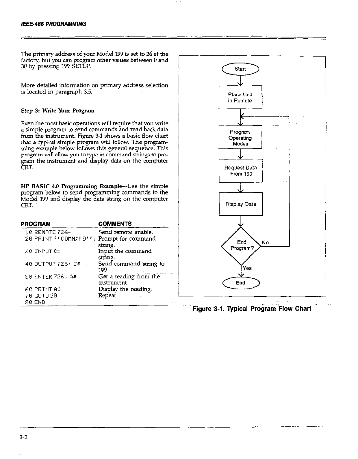
IEEE-488 PROGRAMMING
The @imary address of your Model 199 is set to 26 at the
factory, but you can program other values between 0 and
30 by pressing 199 SEm
More detailed information on primary address selection
is located in paragraph 3.5.
Step 3: Write Your Program
Even the most basic operations will require that you write
a simple program to send commands and read back data
from the instrument. Fig-we 51 shows a basic flow chart
that a typical simple program will follow. The program-
ming example below follows this general sequence. This
program wiU allow you to type in command strings to program the instrument and display data on the computer
CRT.
HP BASIC 4.0 Programming Example-Use the simple
program below to send progmmming commands to the
Model 199 and display the data string on the computer
CRT.
Place Unit
in Remote
v-l
1
I
stting.
4B I:IILITPLIT 7L?:E., C:S ~~~
513 ENTEF: 7:‘i.i k$
93 PEINT AS Display the reading.
7,3 GOT,:, 20
Send command string to
199
Get a r&ding from the
instrument.
Repeat.
End
6
-
Figure t3-1. ‘iypicd ‘Pro&a&l& Chart
3-2
Page 64

IEEE-488 PROGRAMMING
Step 4: F’mgram Model I99 Operating Modes
You can program instrument operating modes by sending
the appropriate command, which is made up of an ASCII
letter representing the command, followed by a numeric
parameter for the command option. Table 3-l summarizes
the commands used to select function and range.
A number of commands can be grouped together in one
string,-if desi?ed.~Also, you must terminate the comrnai~!
or command string with~the X character in order for the
instnunent to execute the commands in question.
If you are using the programming example from Step_3
above, simply type in the command string when prompted
to do so. Some example strings are given below.
F3X select DCA function.
FORZX select DCV function, 3V range.
Table 3-1. IEEE-488 Commands Used to Select Function and Range
Step 5: Get Readings from the Model 199
Usually, you will want to 0btaj1-1 one or more readings from
the Model 199. In the example program above, a single
reading is requested Andy displayed after each command.
fin other cases, you may wish to program the instrument
configuration at the beginning of ,your program, and then
obtain a whole series of measureme&.
The basic reading st+g that the MC&I 199 sends over the
bus is in ASCII characters of the form:
NDCV-123456E+O
where: N indicates a normal reading (0 would indicate an
overflow),
DCV shows the function in effect (iti this case, DC
volts)
-1.23456 is the mantissa of the reading data,
E+O represents the exponent.
Mode
Execute
Function FO DC volts
Range
Command Desaiption
X
E
F3
F4 AC current
E
RO
Rl
R2
E 30 v 30 v 3~ ~A 3 A 30 kSl Auto Auto
R5
R6
R7
Execute other device-dependent commands.
AC volts
Ohms
DC current
ACV dB
ACA dB
DCV AC%’ DCA ACA Ohms
Auto Auto Auto
3QOmV 3CGmV 3OmA 30inA 300 R
3V 3V 3A 3A 3kfl Auto Auto
3ooV.3COV 3A 3 A 3COkQ
3OOV3OOV 3A 3A 3MQ Auto Auto
3ooV3OOV 3A 3 A 3OMR
3ooV3OOV 3A
ACV dB ACA dB
Auto Auto Auto Auto
Auto Auto
Auto Auto
Auto Auto
3 A 3COMfI Auto Auto
33
Page 65

IEEE-488 PROGRAMWNG
3.3 BUS CONNECTIONS
The Model 199 is intended to be connected to the IEEE48
bus through a cable equipped with standard IEEE-488 con-
nectors, an example of which is shown in Figure 3-2. The
connector is designed to be stacked to allow a number of
parallel connections at one instrument. Two scraVs are
located on each connector to ensure that connections re-
main secure. Current standards call for metric threads,
which are identified with dark colored screws. Earlier versions had different screws, which were silver colored. Do
not attempt to use these type of connectors on the Model
199, which is designed for metric threads.
Figure 3-2. IEEE-488 Connector
A typical connecting scheme for a multiple-instrument test:
set up is shown in Figure 3-3. Although any number of
connectors can be stacked on one instnunent, it is recommended that you~stack no more than three connectors on
any one unit to avoid possible mechanical damage.
Figure 3-3. IEEE-488 Connections
Connect the Model 199 to the IEEE-488 bus as follows:
1. Lie up the cable connector with the connector located
on the rear panel of the instrument. The connector is
designed so that it will fit only one way. Figure 34 shows
the location of the IEEE-488 c&nectcW on the
instrument.
2.Tighten the screws securely, butt do not overtighten
_.
met-n.
3. Add additional connectors from other instruments, as
~~ required.
4. Make certain that theother end of the cable is properly
connected to the controller. Most controllers are
equipped with an IEEE-488 style connector, but a few
may requtie a different type of connecting cable. Consult the instruction manual for your controller for the
proper connecting method.
3-4
Page 66

Table 3-2. IEEE Contact Designations
IEEE 488 INTERFACE
Figure 3-4. IEEE-488 Connector Location
NOTE
The IEEE-488 bus is limite~d to a maximum oft I5
devices, including the controller. The madmum
cable length is 20 meters, or 2 meters times the
number of devices, which ever is less. Failure to
observe these limits may result in erratic bus
operation.
Custom cables may be constructed by using the infoqna-~~
tion in Table 3-2 and Figure 3-5. Table 3-2 lists the contact
assignments for the bus, and Figure 3-5 shows the contact
CMfiglX&iO*.
CAUTION
IEEE-488 common is connected to digital common. Maximum voltage between digital common and earth ground is 30V.
CONTACT 12
7
,- CONTACT 1
contact
Number
1
z
4
5
6
i
9
10
11
I.2
13
14
El
17
18
I.9
20
21
z
24
IEEE-488
Designation
DIOl
D102
D103
DIO4
EOI (24)
DAV
NRFD
NDAC
EiJ
P;TN
SHIELD
D105
D106
D107
DIOS
REN (24Y
Gnd, ‘(SF
Gnd, (7)*
Gnd, (8)
Gnd, (9)*
Gnd, (lo)*
Gnd, (ll)*
Gnd. LOGIC
Type
Data
Data
Data
Data
Management
Handshake
Handshake
Handshake
Management
Management
Management
Ground
Data
Data
Data
Data
Management
Ground
Ground
G:ound
Ground
Ground
Ground
Ground
*Numbers in parentheses refer tosignal ground return of
referenced contact number. EOI and REN signal lines
return on contact 24.
3.4 INTERFACE FUNCTION CODES
The interface function codes, which are part of the
IEEE488 standards, define an instrument’s ability to support various interface functions, and they should not be
confused with prograrmning commands found elsewhere
in this manual. Interface function codes for the Model 199
I
are listed in Table 3-3 and are listed for convenience on the
rear panel adjacent to the IEEE-488 connector. The codes
define Model 199 capabilities as follows:
CONTACT24
J
Figure 3-5. Contact Assignments
COKTACT-13
SH (Source Handshake)-SHl defines the ability of the
Model 199 to properly handshake data or command bytes
when the unit is acting as a source.
AH (Acceptor Handshake)-AH1 d&es the ability of the
Model 199 to properly handshake the bus when it is acting as an acceptor of data or commands.
Page 67

IEEE-488 PROGRAMMING
T (Talker)-The ability of the Model 199 to send data over
the bus to other devices is defined by the T function. Model
199 talker capabilities exist only after the instrument has
been addressed to talk.
L (Listener)-The L function defines the ability of the
Model 199 to receive device-dependent data over the bus.
Listener capabilities atist only after the instrument has
been addressed to listen.
SR (Service Request)-The SR function defines the ability
of the Model 199 to request service from the controller.
RL (Remote-Local)-The RL function defmes the capability of the Model 199 to be placed in the remote OI local
modes.
PP (Parallel Poll)-l’he Model 199 does not have parallel
polling capabilities.
DC (Device Clear)-The DC function defmes the ability bf
the Model 199 to be cleared (initialized).
DT (Device Trigger)-The ability for the Model 199 to have
its readings triggered~is defined by the DT function.
C (Controller)-The Model 199 does not have controller
capabilities.
TE (Extended Talker)-The Model 199 does not have extended talker capabilities.
3.5 PRIMARY ADDRESS SELECTION
The Model 199 must receive a listen command before it
will respond to addressed commands over the bus.
Siiarly, the instrument must receive a talk command
before it will transmit its data. These listen and talk commands are derived from the primary address of the instrument, which is set to 26 at the factory. Until you become
more familiar with your instrument, it is recommended
that you leave the address at this value because the programming examples in this manual assume the instrument
is programmed for that address.
The primary address can be programmed for any value
between 0 and 30. However, each device on the bus must
have a unique primary address-- a factor that should be
kept in mind when setting the primary address of the
Model 199. Most connolIers also use a primary address;
consult the controller instnxtion manual for details.
Whatever address is used, it must be the same as the value
specified as part of the contmllefs progtamming language.
To check the presently programmed primary address, OI
to change to a new one, proceed as follows:
1. Press SHE3 DMM SETUP then NEXT. The current
primary address will be displayed. For example, if the
current address is 26, the following message will be
displayed:
LE (Extended Listener)-The Model 199 does not have extended listener capabilities.
E (Bus Driver Type)-The Model 199 has open-collector bus
drivers.
Table 3-3. Model 199 Interface Function Codes
Talker (Basic talker, Serial poll, Unaddressed
Listener (Basic listener, Unaddressed to listen
on TAG)
SRl
RLl
PPO
E:
co
$0
LEO
Service Request capability
Remote/Local capability
No Parallel Poll capability
Device Clear capability
Device Trigger capability
No Controller capability
Open Collector Bus Drivers
No Extended Talker capabilities
No Extended Listener capabilities
26 IEEE
2. To modify the address, key in a new value (O-30) with
the numeric data buttons.
3. To return to normal operation without permanently
changing the address, press NEXT six times in
succession.
4. To store the address as the power up address, first press
NEXT twice, then use uprange to display “SAVE YES.”
Press NEXT three times to return to normal operation.
3.6 CONTROLLER PROGRAMMING
A number of IEEE=488 controllers aTe available, each of
which has its own progra
we will discuss the programming language for the Hewlett-
Packard Series 200 and 300 (BASIC 4.0).
mming language. In this section,
3-6
Page 68

IEEE-488 PROGRAMMING
3.6.1 Controller Handler Software
Before a specific controller can be used over the IEEE-488
bus, it must have lEEE-488 handler sofhvare installed. With
some controllers, the software is located in an optional I/O
ROM, and no software installation is necessary on the part
of the user. In other cases, software must be loaded from
a diskette and initialized.
Other small computers that can be used as IEEE-488 controllers may not support all IEEE488 dictions. With some,
interface programming may depend on the pa&&r interface being used. Many times, little “tricks” are necessary
to obtain the desired results.
From the preceding discussion, the message is clear: make
sure the proper software is being used with the interface.
Often the user may incorrectly suspect that the hardware
is causing a problem, when it was the software all along.
3.6.2 BASIC Interface Programming
Statements
The~programming instructions covered in thii section in-
clude examples written in Hewlett-Packard BASIC 4.0: This
computer language was chosen for the examples because
of its versatility in Controlling the IEEE-488 bus. A partial
list of statements for BASIC 4.0 is shown in Tablet 34.
Statements have a one or three digit argument that must
be specified as part of the statement. The first digit is the
interface select code, which is set to 7 at the factory. The
last two digits of those statements requiring a 3-d@ a.rgument specify the primary address. In the -pies shown,
the default Model 199 address (26) is shown. For a different
address, you would of course change the corresponding
digits in the programming statement.
Some of the statements have two forms, with the exact con-
figuration depending on the command to be sent over the
bus. For example, CLEAR 7 sends a DCL command over
the bus, while CLEAR 726 sends the SDC command to
a device with a primary address of 26.
Table 3-4. BASIC Statements Necessary to Send
Bus Commands
Action
Transmit string to device 26.
Obtain strin& from device 26. ENTER 725 ,i As
Send GTL to device 26.
Send SDC to device 26.
Send DCL to all devices.
Send remote enable.
CanceI remote enable.
Serial poll device 26.
Send Local Lockout.
Send GET to device.
Send IFC.
HP-85 Statement
tj[lTpLlT 726 j A$
LOCAL 72&
CLEW 726
ICLEW 7
REIIOTE 7
Ll3C!qL 7
SF’,jLL /725,)
LOCALS LOCKOIJT 7
3.7 FRONT PANEL ASPECTS OF IEEE-488
OPERATION
The following paragraphs discuss aspects of the front panel
that are part of IEEE-488 operation, including front panel
error messages, lEFZ488 status indicators, and the LOCAL
key.
3.7.1 Front Panel Error Messages
The Model 199 has a number of front panel error messages
associated with IEEE-488 programming. These messages
are intended to inform you of certain conditions that may
occur when sending device-dependent commands to the
instrument, as summarized in ‘Table 3-5.
The following paragraphs discuss each of these messages
in detail. Note that the instrument may be programmed
to generate an SRQ (paragraph 3.9.13), and the Ul error
word can be checked for specific error conditions
(paragraph 3.9.16) if any of these errors occur.
3-7
Page 69

IEEE-488 PROGRAMMING
Table 3-5. Front Panel IEEE-488 Messages
MeSSage Description
NO REMOTE Instrument programmed
with REN false.
IDDC
Illegal Device-dependent
Command
IDDCO
Illegal Device-dependent
Command Option
TRIGGER OVERRUN
Instrument triggered while
it is still processing a
previous trigger.
INTERVAL OVERRUN Instrument cannot store
readings at programmed interval. Readings will be
stored as fast as the instrument can run.
BIG STRING
Progmmmed display
message exceeds 10
characters.
CAL FLOCKED Calibration command sent
with calibration switch in
the disable position.
Z-JAN 4 MAX*
Channel limit is 4 in &pole
mode
SAN 8 MAX’
Channel limit is 8 in Z-pole
mode
*Scanner error messages. See paragraph 3.12.
..,,.,..., ,.. .-~
Note that the NO REMOTE error message is briefly
displayed when the second statement above is executed.
,,..,, ::~,,, ,,
,,,, ,:
,. ,, :: ;
IDDC (Illegal Device-Dependent Command) Error
An IDDC error occurs when the unit receives an invalid
command over the bus. For example, the command string
ElX includes an illegal command because the letter Ed is
not part of the instrumen<s programming language. When
an illegal command is received, the instrument wiil briefly display the following error message:
IDDC
To avoid this error condition, send only valid commands.
Refer to paragraph 3.9 for device-dependent command programming details.
Programming Example-To demonstrate an IDDC error,
use the following statements:
Note that the IDDC errors message iS briefly displayed
when the second statement above is executed.
NOTE: Error messages associated with translator sOftware
are located in paragraph 3.10.
No Remote Error
A no remote error will occur if the instrument receives a
c&fi~e~d~p~&en~ ~~IJIIII~~ andthe~REN(Remote~En
line is false. In this instance, the following error message
will be displayed on the front panel:
NO REMOTE
The error condition can be corrected by placing the REN
line true before attempting to program the instrument.
Programming Fxample-To demonstrate the NO REMOTE
error message, type in the following lines:
LCCAL 7
IDDCO (Illegal Device-Dependent Command Option)
Error
Sending the instrument a legal command with an illegal
option will result in the following front panel error
message:
IDDCO
For example, the command WX has an illegal option (9)
that is not part of the iqshument’s pmgramkng language.
Thus, although the command (Y) itself is valid, the option (9) is not, and the IDDCO errOr will result.
To avoid this error condition, use only valid command options, as discussed in paragraph 3.9.
I’mgamming Example-Demonstrate an IDDCO etir
with the following statements:
3-a
Page 70

IEEE-488 PROGRAMMING
Note that the IDDCO error message is briefly displayed
when the second statement above is executed.
Trigger Overrun Error
A trigger overrun error occurs when the instrument
receives a trigger while still processing a reading from a
previous trigger. Note that any overrun triggers ar$ ignored. These overrun hi ers will not affect the instrument except to generate t e message below. When a tri
e dIsplayed for approximately one second:
i!i
TRIGGER OVERRUN
Programming Example-To demonstrate a trigger
overrun error, enter the following statements into the computer keyboard:
Note that the trigger overrun message is displayed after
the third statement is executed.
l?
8l er overrun occurs, the following front panel message w
RE,+jTE 72%
CAL LOCKED
Interval Overrun Error
A interval overrun error occurs when the instrument can-
not store readin
gr.ammed interv
will continue to store readings as fast as it can nm. The
following message is displayed briefly when a short time
error occurs:
-
Programming Etim
run error, enter t e
computer:
The instrument will stati &&ring readings in the blffer.
However, since the instrument cannot make measurements
at the selected interval (Ismsec), interval overrun errors
will occur.
s
in the data store ore scan at the pro-
ai
(Q command). However, the instrument
INTERVAL OVERRUN
le-To demon&ate an interval over-
R
following statements into the
Big String Error
to display a message
10 characters. Blank
e count as characters. Tl?e
the following message 1s
error occurs:
BIG STRING
“r
to t e computer to demonstrate a big strmg error:
The big string error will occu because the message is made
up-of I2 characters.
Cal Locked Error
A 01 locked error occurs when trying to calibrate the in-
strument over the bus with the front panel calibration
switch in the disable
be i nored
brie y:
‘ng Example-Enter the following statements in-
osition. Calibration commands will
K
and the ollowmg message will Abe displayed
P
3.7.2 IEEE-488 REM~QTE lndiczator and LOCAL
Key
REMOTE-The REM indicator shows when the instrument
is in the remote mode. Note that REM does not necessarily
indicate the state of the REN line, as the instrument must
be addressed to listen, with REN true before the REM in-
dicator will turn on. When the instrument is in remote,
all front panel keys except for the LOCAL key will be locked out. When REM is turned off, the instrument is in the
local mode.
LOCAL-The LOCAL key cancels the remote mode and
restores @al operation of the instrument.
Since all front panel keys except LOCAL are locked out
when the instrument is in remote, thii key provides a convenient method of restoring front panel operation. Press-
ing LOCAL will also turn off the REM indicator and return
the display to the normal mode if user messages were
previously displayed with the D command.
Note that the LOCAL key will also be inoperative if the
LLO (Local Lockout) command is in effect.
3-9
Page 71

IEEE-488 PROGRAMMING
3.8 GENERAL BUS COMMAND
PROGRAMMING
Generd bus commands are those commands such as DCL
that have the same general purpose regardless of the instrument. Con%naxids supported by the Model 199 are
summarized in I3ble 3-6, which lists BASIC 4.0 statements
necessary to send each command. Note that commands
requiring a primary address assume that the Model 199
primary address is set to 26 (its factory default~address).
3.8.1 REN (Remote Enable)
REN is a uniline command that must be asserted by the
controller to place the Model 199 in remote. Simply set-
ting EN true will not adually place the instrument in
remote; instead, the unit must be addressed to listen after
REN is set true.
Generally, remote enable should be asserted before attempting to program the instrument over the bus. Once
the instrument is in remote, all front panel controls except
LOCAL~will be inoperative. Normal front panel operation
can be restored by pressing the LOCAL key.
To place the Model 199 in remote, the controller must per-
form the following sequence:
Pmgxamming Example-Place the Model 199 in remote
with the following statement:
PEMOTE 7215
The Model 199 should be in remote, as indicated by the
annunciator light. If not, check to see that proper bus connections are made, and that the instrument is programmed for the correct primary address (26).
Note that all front panel controls except LQCAL (and, of
course, POWER) are inoperative while the inshument is
in remote. You can restore normal front panel operation
by pressing the LOCAL button.
3.8.2 IFC (Interface Clear)
The FC command is sent by the controller to place the
Model 199 in the talker and listener idle states. The~unit
will respond to the IFC command by cancelling TALK or
LISTEN, if the instrument was previously placed in one
of those modes.
To send the IFC command, the controller need only set
the IFC line true for a minimum of 1OO~sec.
1. Set the REN line true.
2. Address the Model 199 to listen.
Table 3-6. General Bus Commands and Associated BASIC Statements
BASIC 4.0~
Statement
REMOTE 7 Goes into remote when next addressed.
IZIEORT 7 Goes into talker and listener idle states.
LOCAL LljC:Kijl-lT ;
LljCkL 726
C’LEAR 7
CLEAR 726
TF: I GGER 725. Triggers reading in TZ and T3 modes.
Affect on Model 199
Front LOCAL key locked out.
Cancel remote.
Returns to default conditions.
Returns to default conditions.
3-10
Page 72

IEEE-488 PROGRAMMING
3.8.3 LLO (Local Lockout)
The LLO command is used to lock out operation of the
LOCAL key, thereby completely locking out, fro?t panel
operation of the instrument (recall that the remaining controls are locked out when the instrument is placed in
remote).
To send the LLO command, the controller must perform
the following steps:
1. Set ATN true.
2. Place the LLO command byte on the data bus.
To cancel local lockout and return control to the front
panel, REN must be set false by sending the LOCAL 7
command to the instrument.
Programming example-To verify LLO operation, enter the
following statements:
FEMOTE 726.
LIXRL LOCl;rJUT 7
After the second statement is executed, the LOCAL key
will be locked out.
Programming Example-Place the instrument in the
remote mode with the following statement:
REMCITE 726
Verify that the instrument is in remote.
Send GTL as follows:
.-..
Note that the instrument goes into the local m~ode, and
that operation of the front panel keys has now been
restored.
3.8.5 DCL (Device Clear)
The DCL command may be used to clear the Model 199
and return it to its default conditions. Note that the DCL
command is not an addressed command, so a31 instruments equipped to implement DCL wiU do so
simultaneously. When the Model 199 receives a DCL com&and, it will return to default conditions (see paragraph
3.9.11). %ble 3-7 lists factory default conditions.
Table 3-7. Factory Default Conditions
To cancel LLO, type in the following statement:
When END LINE is pressed, control to the front panel will
be restored.
3.8.4 GTL (Go To Local)
The GTL command is used to take the instrument out of
the remote mode and restore operation of the front panel
keys.
To send GTL, the controller must perform the following
sequence:
1. Set ATN true.
2. Address the Model 199 to listen.
3. Place the GTL command byte on the data lines.
The GTL command will not cancel LLO (local lockout)
since it does not set REN false.
Mode
Multiplex*
Reading
Function*
Data Format
Self-Test
EOI
SRQ
Filter*
Interval’
Data Store Size’
Range*
Rate*
Trigger
Delay’
Terminator
Zero
These defaults can be changed. See paragraph 3.9.11.
Command
Al
BO
E
JO
Ko
MO
E
IO
R4
Sl
T6
wo
zi
Enabled
A/D converter
DC volts
Send prefix with
reading
Clear
Enable EOI and bus
hold-off on X
Disabled
Internal enabled
l75msec (SELECT
OFF)
Coniinuous
3oov
SYzd, line cycle
integration
continuous on ex-
ternal trigger
No delay
CR LF
Disabled
3-11
Page 73

lEEE-488 PROGRAMMING
To send the DCL command, the controller must perform
the following steps:
1. Set ATN true.
2. Place the DCL command byte on the data bus.
Notes:
1. DCL will return the instrument to the default line frequency setting.
2. DCL will not have any effect on the current IEEE
address.
Programming Example--Place the unit in an operating
mode that is not a default condition. Now enter the following statement into the keyboard:
Note that the instrument returns to the default conditions.
3.8.6 SDC (Selective Device Clear)
The SDC command is an addressed command that per-
forms essentially the same function as the DCL command.
However, since each device must be individually addressed, the SDC command provides a method to clear only
a single, selected instrument instead of clearing all instruments simultaneously, as is the case with DCL.-When
the Model 199 receives the SDC command, it wil1 return
to the default conditions (see paragraph 3.9.11). Table 37
lists factory default conditions.
i. <DC will not have any effect on the current IEEE
address.
Programming Example-Using several front panel con-
trols, alter instrument states from the default configura-
tion Send SDC with the following statement:
When the above statement is executed, the instrument
returns to the default configuration.
3.8.7 GET (Group Execute Trigger)
GET may be used to initiate a Model 199 measurement sequence if the instrument is placed in the appropriate trigger mode (see paragraph 3.9). Once triggered, the instru-
ment will take a single reading or series of readings.
To send GET the controller must perform the following
sequence:-
1. Set ATN low.
2. Address the Model 199 to listen.
3. Place the GET command byte on the data bus.
Programming Example-Type in the following statements
to place the instrument in the correct hitzger mode for purposes of this demonstration:
To transmit the SDC command, the controller must per-
form the following steps:
1. Set ATN true.
2. Address the Model 199 to listen.
3. Place the SDC command byte on the data bus.
Notes:
1. SDC~ will return the instrument to the default line fre-
quency setting.
3-12
Now trigger the reading by sending GET with the following statement:
The reading will be triggered when the statement is
executed.
Page 74

IEEE-488 PROGRAMMING
3.8.8 Serial Polling (SPE,SPD)
The serial poIIing sequence is used to obtain the Model
199 serial poll byte. The serial poIl byte contains important information about internal functions, as described in
paragraph 3.9.13. The serial polIing sequence can also be
used by the controller to determine which instrument on
the bus has asserted SRQ (Service Request):
The serial polling sequence is generally conducted asp
follows:
1. The contrder sets P;IN true.
2. The controller then places the SPE (Serial Poll Enable)
command byte on the data bus. At this point; all active
devices are in the serial poll enabled mode and waiting~
to be addressed.
3. The Model 199 is then addressed to talk.
4. The controller sets ATN fake.
5. The instrument places its serial poll byte on the data
bus to be read by the controller.
6. The controlher then sets ATN true and places the SPD
(Serial Poll Disable) command byte on the data bus to
end the serial polling sequence.
ample, a command to control the measuring function is
programmed by sending an ASCII “F” followed by a
number representing the function option.
A number of commands may be grouped together in one
string. A command string is usuaIly terminated with an
ASCII “X” character, which tells the instrument to execute
the command stxing. Commands sent without the execute
character will not be executed at that time, but they will
be retained within an internal command buffer for execution at the time the X character is received. If any errors
occur, the instrument wilI display appropriate front panel
error messages and generate an SRQ if prograkned to do
so.
Commands that affect instrument operation will trigger a
reading when the command is executed. These bus commands affect the Model 199 much Iike the front pane1 controls. Note that commands are not necessarily executed in
the order received; instead, they will be executed in
alphabetical order. Thus to force a particular command sequence, you would follow each command with the execute
character (X),~ as in the example sting, L.OXF2X, which will
reset the instrument to factory default conditions and then
select the ohms function.
Once instrumtiiits are in the serial poll mode, steps 3
through 5 above can be repeated by sending the correct
talk address for each instrument.
Programming Example-The SI’OLL statement
automatically performs the sequence just described. TO
demonstrate serial polling, type in the following program
lines:
When the above program is executed, the Model 199 is
serial polled, and the decimal value of the serial poll byte
is displayed on the computer CRT.
3.9 DEVICE-DEPENDENT COMMAND
PROGRAMMING
IEEE-488 device-dependent commands are used with the
Model 199 to control various operating modes such as
function, range, trigger mode and data format. Each command is made up of a single ASCII letter followed by a
number representing an option of that command. For ex-
Device-dependent commands can be sent either one at a
time, or in groups of several commands within a single
string. Some examples of valid command strings indude:
FOX-Single command string.
FOKlPOROX-Multiple command string.
T6 X-Spaces are ignored.
Typical invalid command stings iriclude:
ED&-Invalid command, as E is not one of the instrument
commands.
F15X-Invalid command option because 15 is not an option
of the F command.
If-an illegal command (IDDC), illegal command option
(IDDCO), is sent, or if a command string is sent with REN
false, the string will not be executed.
Device-dependent commands that control the Model 199
itself are listed in Table 3-8 (Scanner programming is
covered separately in paragraph 3.12). These commands
are covered in detail in the foIloWing paragraphs. The
associated programming examples show how to send the
commands from BASIC 4.0.
3-w
Page 75

Notes:
1. Programming examples assume that the Model 199 is
at its factory default value of 26.
2. Device dependent commands sent over the bus while
the unit is in a front panel menu will be ignored. Before
programming over the bus, press NEXT as many times
as necessary to exit the menu.
Table 3-8. Device-Dependent Command Summary
In order to send a device-dependent command, the controller must perform the following steps:
L Set ATN tme.
2. Address the Model 199 to listen.
3. Set ATN false.
4. Send the command string over the bus one byte at a
time.
teading Mode
Ma Store Size
T.5
T6
37
BO
Bl
B2
IO
In
Auto Auto Auto
300mV 3OOmV 30mA 30mA 300
3V 3V 3A 3A
30 V 30 V 3 A 3 A 30 kfl
3OOV3OOV 3A 3AUK)kR Auto
3oOV3OOV 3A 3A
V 3 A 3 A 3OMQ Auto
Confinuous on x
One-shot on X
Continuous on External Trigger
One-shot on External Triger
Readings from AID converter
Individual readings from data store
All readiigs from data store (buffer dump)
Wrap around data store mode
Data store of n (n=l to 500)
Auto
Auto
3MQ Auto
3.9.8
3.9.9
3-14
Page 76

Table 3-8. Device-Dependent Command Summary (Cont.)
Reading with prefuc.
IEEE-488 PROGRAMMING
stah.ls
Multiplex
Delay
Self-test
Hit Button
Display
UO
Ul
iii
u4
U5
A0
Al
Wn
JO
Hn
Da
D
Data store half full
Disable both EOI and bus
Send machine status word
Send error conditions
Send Translator word list
Send buffer size
Send current value of “V”
Send input switch status (front/rear)
Auto/Cal multiplex disabled
Auto/Cal multiplex enabled
n=delay period in milliseconds, (Omsec to 999999msec)
Test, ROM, RAM, ETROM
Hit front panels ~xtton number n
Display up to 10 character message. a=character
Cancel display mode
hold-off on X
3.9.16
3.927
3.9.18
3.9.19
3.9.20
3.92
3-15
Page 77

IEEE-488 PROGRAMMING
NOTES:
1. RFN must be true when sending device-dependent commands to the instrument, or it will ignore the command
and display a bus error message.
2. Scanner programming commands are covered in
paragraph 3.12.
General Programming Example-Device-dependent cornmands may be sent from the computer with the following statement:
A$ in this case contains the ASCII characters representing
the command string.
3.9.1 Execute (X)
The tiecute command is implemented by sending an
ASCII “X” over the bus. Its purpose is to direct the Mod&l
199 to execute other device-dependent commands such as
F (fwxtion) or R (range). Usually, the execute character
is the last byte in the command string (a number of commands may be grouped together into one string); however,
there may be certain circumstances where it is desirable
to send a command string @ one time, and then send the
execute character later on. Command strings sent without
the execute character will be stored within an internal cornmand buffer for later execution. When the X character is
finally transmitted, the stored commands will be executed,
assuming that all commands in the previous string were
valid.
Programming Example-Enter the following statements into the keyboard:
ment responds to a function command, it will be ready
tog take a reading once the front end is set up. The function may be programmed by sending one of the following
commands:
FO = DC~ Volts
FI = AC Volts
FZ = Ohms
F3 = DC Current
F4 = AC Current
F5 = ACV dB
F6 ~= ACA dB
Upon power up, or after the instrument receives a DCL
or SDCcommand, the Model 199 will return to the default
condition.
Programming Example-Place the instrument in the ohms
function by pressing the OHMS button and enter the
following statements into the computer keyboard:
When FOX is executed, the instrument changes to DCvolts.
3.9.3 Range (R)
The range command gives the user control over the sen-
sitivity of the instrument. This command, and its options,
perform essentially the same functions as the front panel
Range buttons. Range command parameters and the
*Spective ranges for each measuring function are summarized in Table 3-9. The instrument will be ready to take
a reading after the range is set up when responding to a
range command.
The X-character will be transmitted to the insinunent. No
mode changes will occur with this example because no
other commands were sent. Note that the instrument remains in the listener active state after the command is
transmitted.
3.9.2 Function (F)
The function command allows the user to select the type
of measurement made by the Model 199. When the in&u-
3-16
Upon power up, or after the instrument receives a DCL
or SDC command, the Model 159 will return to the default
condition.
hgrammi
the autorange mode and then enter the following
statements into the computer:
ng Example-Make sure the instrument is in
Page 78

Table 3-9. Range Command Summary
IEEE-488 PROGRAMMING
Command DCV ACV DCA 1 ACA 1 Ohms
Auto Auto
3OOmv 3OOmv 3omA 3omA 300 cl
R2 1 3 VI 3 VI 3 Al 3 A I 3kO
I
R3 30 V 30 V
R4 300 V 3CO V
l-6 300 V 300 V
R6 300 V 300 V
W 13OOV13OOV/ 3AI iA13OOMQ
I
The instrument cancels the autorange mode, and enters
the R3 range instead.
3.9.4 Zero (Z)
Ovei the bus, the zero modifier can be controlled in the
same way that it is controlled from the front panel. Refer
to paragraph 2.6.2 for a complete description of the zero
mod9ier. The zero modifier is contmlled by sending one
of the following zero commands over the bus:
ZO = Zero disabled.
ZIP = Zero enabled.
22 = Zero enabled using a zero value (V).
Auto Auto Auto
3 A 3 A 30 kQ
3 A 3 A 3LXIkQ
3 A 3 A 3Mi-l
3 A 3 A 30MR
Range
F’rogramming Example-Se;
range. With the front panel ;
mode, if enabled, and enter
the HP-85 keyboard:
Aft&r the third statement, the ZERO indicator Wi!.l turn on
with a zero baseline of 1VDC.
3.9.5 Filter (P)
T
I
\CA dB
Auto
Auto
Auto
Auto
Auto
Auto
Auto
Auto
1
-
t tt \e instrument to the 3V DC
ZE: RO button disable the zero
th< e following statements into
1
Sending Zl has the same effect as pressing the ZERO button. Zero will enable, and the display will zero with the
input signal becoming the zero baseline level.
The 72 command is used when a zero value, using the
V command, has already been established. When the 22
command is sent, subsequent readings represent the difference between the input signal and the value of V. For
example, with 0.5V on the input, sending the command
stings V2XZZ-X will result with zero being enabled and
the instrument reading -19 (0.5 -2.0 = -1.5). If 30 V
is value is programmed, a value of 0 is assumed.
NOTE
In a one-shot trigger mode, you must trigger the
unit after sending the Z command to complete
zero programming. ZERO will flash after sending
Zl until the “nit is triggered.
Upon power up or after the instrument receives a DCL
or SDC command, the Model 199 will return to the default
condition.
The filter command controls the amount of filtering ap-
plied to the input signal. The Model 199 filters the signal
by taking the average of a number of successive reading
samples. Since noise his mostly ran&G inky nature, It can
be largely cancelled out with this method. Paragraph 2.6.3
discusses filtering in more detail.
PO = No filtering
Pl = Internal filter enabled
l’2 = Front panel filter enabled
Upon power up or after the instrument receives a DCL
or SDC command, the Model 199 will return to the default
condition.
Programming Example-With the front panel FILTER indicator off, enter the following statements into the
computer.
347
Page 79

The filter will turn on.
quired to start each conversion. The Model 199 has eight
trigger commands as follows:
3.9.6 Rate (S)
The rate command controls the integration period and the
usable resolution of the Model 199. Table 3-10 lists the
usable resolution on each function for the two S modes.
The integration period is dependent on usable resolution
as shown in Table 3-10.
Upon power up or after the instrument receives a DCL
or SDC conimand, the Model 199 will return to the default
condition.
Programming Example-From the front panel, set the
display of the Model 199 for DCV at 4%d resolution. Now
enter the following statements into the computer:
When END LJNE is pressed the second time, the Sl rate
will be selected (5% digit resolution).
Table 3-10. Rate Command Summary
TO = Continuous on Talk
Tl = One-shot on Talk
T2~ = Continuous on GET
T3 = One-shot on GET
T4 = Continuous on X
T5 = One-shot on X
T6 = Continuous on External Tr&er
l7 = One-shot on External Trigger
The trigger modes are paired acqorc#ng to the type of
stimulus that is used to trigger the instrument. In the ‘ITI
and Tl modes, triggeling is performed by addressing the
Model 199 to talk. In the T2 and T3 modes, the IEEE-488
multiline GET command performs the trigger function.
The instrument execute (X) character provides the trigger
stimulus in the T4 and T5 modes. External trigger pulses
provide the trigger stimulus in the T6 and T7 modes.
Upon power up or after the instrument receives a DCL
or SDC command, the Model 199 will return to the default
condition.
NOTES:~
1. The front panel TRIGGER button can be used to trig-
ger readings. See paragraph 2.8 for details.
2. In T6, the unit provides its own trigger.
?Omsec @ 50Hz, 16.67msec @ 6OHz.
3.9.7 Trigger Mode (T)
Triggering provides a stimuh~s to begin a reading conversion withii the instrument. Triggering may be done h two
basic ways: in a continuous mode, a single trigger command is used to start a continuous series of readings; 111
a one-shot trigger mode, a separate trigger stimulus is re-
3-18
Programming Example--Place the instrument in the one-
shot on talk mode with the following program:
1 B F:EtlDTE 726
In this example, the ENTER statement addresses the Model
~199 to talk, at which point a single reading is triggered.
When the reading has been processed, it is sent out over
the bus to the computer, which then displays the result.
Page 80

IEEE-488 PROGRAMMING
3.9.8 Reading Mode (B)
The reading mode command parameters allow the selection of the source of data that is transmitted over the
IEEE-488 bus. Through this command, the user has a
choice of data from the A/D converter (normal DMM
readings) or the buffer (data store). The reading mode corn-
mands are as follows:
BO = AID converter readings
Bl = Single Data Store readings
B2 = All Data Store readings
Upon power up or after the instrument receives a DCL
or SDC command, the Model 199 will return to the default
condition.
When in BO, normal A/D readings will be sent. In a continuous trigger mode, readings will be updated at the conversion rate. The Bl command is used to access single
readings from the buffer. When the Bl command is sent,
subsequent readings will be taken from consecutive buffer locations beginning with the first memory location
(001). Once all readings have been requested, the last location will be continuously sent.
acquire the reading and display it on the CRT.
3.9.9 Data Store Interval (Q) and Size (I)
The data store is controlled by the interval command (Q)
and the size command (r).
With the Q command, the user can sele.ct the interval that
the instrument will store readings?& Q command is in
the following form:
QO=l75msec default interval (SELECT OFF)
Qn=Set interval in mill&c (L5msec to 999999msec).
Note that the programmed interval also affects the interval between readings, and scan interval.
To store readings at a selected interval (Qn), the instru-
ment must beg in a continuous trigger mode (TO, T2, T4,
T6). When the selected trigger occurs, the storage process
will commence.
The 82 command allows you to dump the entire data store
contents to the computer in one operation. Individual
readings will be separated by commas, and the selected
data format will apply to each reading. Data fields not applicable to the requested operation will be filIed~ with
zeroes. Also, the programmed terminator and EOI will be
asserted at the end of the complete dump--not after each
reading as is the case with the Bl mode.
NOTE
In Bl or B2 nothing will be transmitted over the
bus until data is stored in data store.
progamming Example-Enter the following statements in-
to the computer to send a reading over the bus and display
it on the computer CRT.
The second statement above sets the instrument to the A/D
converter reading mode. The thii and fourth statements
One-Shot Trigger Into Data Store
To use the data store in the one-shot mode, the instrument
must be in a one-shot trigger mode (Tl, l3, T5 or T7). In
the Tl mode, one reading will be stored each time the instrument is addressed to talk. In the T3 mode, each GET
command will cause one reading to be stored. In the T5
mode, each instrument execute character (X) will cause a
reading to be stored. Finally, in the ‘I7 mode, each exter-
nal trigger pulse will cause a reading to be stored.
Size
The size of the data store can be controlled by one of the
following I commands.
IO=Wrap around storage mode.
In=Set data store size to n (1 to 500).
In the wrap around data storage mode (IO), storage will
not stop after the buffer is fried (500 readings), but will
proceed back to the first memory location and start over-
writing data. With the Innn command, the storage pro-
cess will stop when the defined number of readings have
been stored. In this case the buffer is considered to be full.
3-19
Page 81

fE&E-488 PROGRAMMING
NOTES:
1. Sending the I command enables data store; however,
the unit must be properly triggered to begin storage once
data store is enabled.
2. When the I command is sent, ‘i-----L’ will be displayed
until the fast trigger occurs.
3. The data store can be disabled by sending the F
command.
4. The INTERVAL OVERRUN error message indicates that
the instrument cannot store readings at~the programmed interval rate. Instead, readings will be stored as fast
as the instrument can run.
5. Either during or after the storage process, readings may
be recalled by using the Bl or B2 command as described in the previous paragraph.
then request and display all 100 readings (lines 60-100).
3.9.10 Value &) and Calibration (C)
One advanced feature of the Model 199 is its digital calibra-
~tion~capabilities. instead of the more diificult method of
adjusting a number of potentiometers, the user need only apply an appropriate calibration signal and send the
calibration value over the bus.
The V command is also used to program a zero value (see
paragraph 3.9.4).
The value command may take on either of the following
forms:
Vnn.nnnnn
Vn.nnnnnnE+n
Thus, the following two commands would be equivalent:
v30
vAOE+1
Upon power up or after the instrument receives a DCL~
or SDC command, the Model 199 will return to the default
condition.
Programming Example-Enter the program below to
enabIe data store operation and obtain and dispIay 100
readiigs on the computer CRT:
PROGRAM
COMMENTS
Send remote enable,
Set trigger mode, and
storage parameters.
start storage process.
Set read mode to data
~siore.
Set counter for Xl0
hp.
Get a reading.
Display reading.
Loop back for next
reading.
In this example, note that only as many significant digits
as necessary need be sent. In this case, the exact value is
assumed to be 3O.COOO even though only the first two digitz
were actually sent.
Digital Calibration-When performing digital calibration,
two (three for DCVj points must be calibrated on each
range. The first calibration value should be approximately
full range and the second calibration value should be approximately zero. ,(The third point is at minus foul1 range
for DCV only). After the second or third calibration value
is sent over the bus, permanent storage of the two values
will occm.
In order to send calibration values over the bus, the c&bra-
tion command (C) must be sent after the value command
(V) is sent. The calibration command takes an the following form:
CO=Calibrate fast point using value (*
Cl=Calibrate second point using value (v)
U=Calibrate third point using value (V)
After entering the program, press the RUN key. The pro-
gram wilI set the store size to 100 (line Xl), enable the data
store (line 40), turn 011 the data store output (line XI), and
3-20
The following example first sends a calibration value of 3
and then a calibration of 0.
v3xcox
voxclx
Page 82

IEEE-488 PROGRAMMING
If the calibration value is greater than 303000 counts (at
5’hd resolution) an IDDCO ermr message will be displayed
on the Model 199.
CAUTION
Precision calibration signals must be connected
to the instrument before attempting calibration,
othewise instrument accuracy will be affected.
See Section 6 for complete details on calibrating the instrument either from the front
panel or over the bus.
3.9.11 Default Conditions (L)
The I.0 command allows the user to return the instrument
to the factory default conditions. Factory default conditions
are set at the factory and are listed in Tables 3-7 and 2-l.
The instrument will power up to these default conditions.
The went IEEE address and line frequency setting of the
instrument are not affected by the LO command.
The Ll command is used to save the current instrument
conditions. The instrument will then power up to these
default conditions.
Any of the options of the following device-dependent commands can be saved as the default conditions:
A (multiplex), F (function), P (Filter), Q and I (reading interval and size), R (range), S (rate), W (trigger delay), and
z (zero).
3.9.12 Data Format (G)
The G command controls the format of the data that the
instrument sends over the bus. Readings may be sent with
or without prefixes. I’refixes are the mnemonics preceding
the reading and the buffer memory location. Figure 3-6
further clarifies the general data format. The G commands
are a5 follows:
GO = Reading with prefw only. Example:
NDCV-1234567E+O
Gl = Reading without prefix. Example:
-1.234567EtO
G2 = Reading and buffer memory location with prefix.
Etimple: NDCV-1234567E+O,BOOl
G3 = Readings and buffer memory without prefix.
Example: -1.234567E+O,oOl.
G4 = Reading and channel with prefix. Example:
NDC-1234567E+O,Cl
G5 = Reading and channel without prefix. Example:
-1.234567EeO.l
G6 = Reading memory buffer location, and channel with
prefix. Example: NDCV-1.234567E+O,BOOl,Cl
G7 = Reading buffer memory location, and channel
without prefix. Example:
-1.234567E+O,OOl,Ol
Upon power up or after the instrument receives a DCL
or SDC command, the Model 199 wiJ.l return to the default
condition.
Notes:
The L command options are as follows:
J&Restore instrument to factory default conditions and
save (Ll).
Ll=Save present machine states as the default conditions.
Programming Example-Set the Model 199 to the ohms
function, and enable zero and filter. Now, enter the following statements into the computer:
After the second statement, cycle power on the Model 199
and note that the instrument returns to the conditions initially set in this example.
1. The B command affects the source of the data. In the
BO mode, the bus data wilI come from the A/D converter.
In the Bl and B2 modes, the data will come from the
buffer.
2. Programmed terminator and EOI sequences appear at
the end of each reading except in 82 which terminates
only at the end of the string.
3. If a buffer location or channel is not available, zero is
sent. G6 Ewinple: NLKV+2.000lOOE+1,8000,C0.
4. All 9s appear in the data field for an overflow.
Programming Example-To place the in&ument in the Gl
mode and obtain a reading, enter the following statements
into the keyboard:
3-21
Page 83

DCV = DC Volts
ACV = AC Volts
OHM = Ohms
dl3V I AC dB Volts
dBI = AC d5 Amps
RAT = Rata
Notes : 1. Buffer Location 3 BOO0 with Data Store Disabled
2. Channel = CO with no Scanner or
Scanner Disabled
Figure 3-6. General Data Format
When the second statement is executed, the instrument
will change to the Gl mode. The last two statements acquire data from the instrument and display the reading
string on the CRT. Note that no prefu or suffix appears
on the data string.
3.9.13 SRQ Mask (M) and Serial Poll Byte
Format
The SRQ command controls which of a number of condi-
tions within the Model 199 will cause the instrument to
reque$ service from the controller by asserting an SRQ.
Once an SRQ is generated, that serial poll byte can be
checked to determine if the Model 199 was the instrument
that asserted the SRQ and if so, what conditions can be
checked by using the Ul command, as described in
paragraph 3.9.13.
The Model 199 can be programmed to generate an SRQ
under one or more of the following conditions:
1. When a reading is completed or an overrange condition
OCCUIS.
2. If a bus error occurs.
3. When the data store is full.
4. When the data store is ‘h full.
5. If a trigger overrun error occurs.
Upon power up or after a DCL or SDC command is re-
ceived, SRQ is disabled.
SRQ Mask-The Model 199 uses an internal mask to determine which conditions wiU cause an SRQ to be generated.
Figure 3-7 shows the general format of this mask.
SRQ can be programmed by sending the ASCII letter “M”
followed by a decimal number to-set the appropriate bit
in the SRQ mask. Decimal values for the various bits sre
summarized in Table 3-K Note that the instrument may
be programmed for more than one set of conditions
simultaneously. To do so, simply add up the decimal bit
values for the required SRQ conditions. For example, to
enable SRQ under reading overflow and buffer full conditions, send M3X. To disable SRQ, send MOX. This command will clear all bits in the SRQ mask.
Serial PoII Byte Porma&The serial poIl byte contains in5x%&on relating to data and error conditions within the
instrument. The general format of the serial poll byte
(which is obtained by using the serial polling sequence,
as described in paragraph 3.88) is shown in Figure 3-7.
Page 84

&n~ 87 q 6 B5 84 83 B2 Bl BO
Figure 3-7. SRQ Mask and Serial Poll Byte Format
Table 3-11. SRQ Command Parameters
Command Condition to Generate SRQ
MO Disable
Reading overflow
zi
M4 Data store half full
M8 Reading done
Ml6 Ready
M32 Error
The bits in the serial poll byte have the following meanings:
Bit 0 (Reading Overflow)-Set when an overrange input
is applied to the instrument. Clexed when the input is
on range.
Bit 1 (Data Store)-Set when the defined data store size
Bit 2 (Data Store % Full)-Set when half the defied data
store size is full. Cleared by re-enabling data stoic.
Bit 3 (Reading Done)-Set when the instrument has CO~-~
pleted the present reading conversion. Cleared while processing a reading.
Bit 4 (Ready)-Set when the instrument has processed all
previously received commands and is ready to accept ad-
ditional commands over the bus. Cleared while the in&ument is processing commands.
Bit 5 (Error)-Set when one of the following errors has
occurred:
Data store full
I kr .a-,,&L7 data s@re.
1. Trigger Ovemn
2. Interval overrun
,3. Big String
4. Uncalibrated
5. Cal Locked
6. Conflict
7. No Remote
8. IDDC
9. IDDCO magi
10. Translator
Il. No Scanner
12. Chan 4 Maximum
13. Channel 8 Maximum
The error bit is cleared by reading the Ul word.
The n&w: of the error can beg determined with the Ul
command as explained in paragraph 3.9.16. An explanation of each error can also be found in paragraph 3.9.16.
Bit 6 (RQS)--Provides a means to Deb ‘* ^-^ tennUke d an bKv was
asserted by the Model 199. If this 1
requested b ”
y me uwrurnenr.
bit is set, service was
Bit 7-Not used and always set to zero.
Note that the status byte should be read to clear the SRQ
line once the instrument has generated an SRQ. All bits
in the status byte will be latched when the SRQ is
generated. Bit 6 (RQS) ~2 be deared when the status byte
is read.
3-23
Page 85

IEEE-488 PROGRAMMING
Programming Example-Enter the following progixm ifi- K2 = Send EOI with last byte; do not hold off bus on X.
to the computer:
K3 = Send no EOI with last byte; do not hold off bus on X.
COMMENTS
Seth up for rein&e
operation.
illegal -option. Serial poll the
instrument.
45 IF IDIOT EITcSI 5) THEN 46 Wait for SRQ error.
50 PRItlT ( i E7 EE, ES B4 133
Once the program is entered and checked for errors, press
the RUN key. The computer first places the instrument in
remote (line 10) and then programs the SRQ mode of the
instrument (liie 20). Line 30 then attempts to program an illegal command option, at which point the instrument generates an SRQ and sets the bus error bit in
its status byte. The computer then serial polls the instrument (line 40), and then displays the status byte bits in
proper order on the CRT In this example, the SRQ (B6)
and error (B5) bits are set because of the attempt to program an illegal command option (K5). Other bits may also
be set-depending on instrument status.
Identifv the bits.
Loop eight times.~
Display each bit
positi ion.
Upon power up, or after the instrument receives a DCL
or SDC command, the instrument will return to Ko.
The EOI line on the IEEE-488 bus provides a method to
positively identify the last byte in a multi-byte transfer sequence. Keep in mind that some controllers rely on EOI
to terminate their input sequences. In this case, suppressing EOI with the K command may cause the controller input sequence to hang unless other terminator sequences
are used.
The bus hold off mode allows the instrument to temporti-
!y hold up bus operation when it receives the X character
until it processes all commands sent in the command
string. The purpose of the hold off is to &sure that the
front end FETs and relays are properly configured before
taking a reading. Keep in mind that all bus operation will
cease--not just activity associated with the Model 199. The
advantage of this mode is that no bus commands will be
missed while the instrument is processing commands
previously received.
The hold off period depends on the commands being processed. Table 3l2 lists hold off times for a number of different commands. Since a NRFD hold off is employed, the
handshake sequence for the X character is complete.
NOTE
With KO or Kl asserted, hold-off will also occur on
an EOI and a terminator. These delavs allow for
proper operation of the Translator sortware, since
“X” cannot be used in Translator words.
3.9.14 EOI and Bus Hold-off Modes (K)
The K command allows control over whether or not the
instxument sends the EOI command at the end of its data
sting, and whether or not bus activity is held off (through
the NRFD line) until all commands sent to the instrument
are internally processed once the instrument receives the
X character. K command options include:
Kfl = Send EOI with last byte; hold off bus until corn-
mands processed on X.
Kl = Do not send EOI with last byte; hold off bus until
commands processed on X.
324
Pmgmmning Example-To program the instrument for the
K2 mode, enter the following statements into the
computer:
When the second statement is executed, the instrument
will be placed in the K2 mode. In this mode, EOI will still
be Bansmitted at the end of the data string, but the bus
hold-off mode will be disabled.
Page 86

Table 3-12. Bus Hold-off Times (Typical)
Typical
Command
AO-Al
FO-Fl
F5-F6
BO-81
GO-G1
JO-P
K&K1
MO-Ml
NO-N1
DN99- Dx
00-01
QlO-Q20
RO-Rl
IQ-R3
so-s1
m-n
W20-W40
YO-M
zo-Zl
I20-I30
Lo-L1
co- Cl
PO-p1
Note: Hold-off ocCurs on X or <CR> <LF-> when
enabled.
Hold Off Time
l76msec
105msec ~~ _ ~-~
16omsec
49msec
58msec
lJ5msec
57msec
57msec
105llW.X
55msec
104msec’
lffimsec
106msec
105msec
l58msec
lO2msec
lU7llISW
58msec
105msec
lmnsec
1OOmsec
8.85s~~ (DCV) l8sec (ZOMQ)
106msec
3.9.15 Terminator (Y)
The terminator sequence that marks the end of the in&umerit’s data shing or status word can be programmed by
sending the Y command followed by an appropriate
number. The default terminator sequence is the commonly
used carriage return, line feed (CR LF) sequence (YU). The
terminator will assume this default value upon power up,
or after the instrument receives a DCL or SDC command.~
Programmable terminators include:
YO=CRLF
Yl = LFCR
Y2 = CR
YJ=LF
HP-85 Programming Example-To reserve the default (CR
LF) terminator sequence, type the following lines into the
computer.
EE-488 PROGRAMMING
When the second statement is executed, the normal terminator sequence~tiill be reserved; the instrument will terminate each data string or status word with a (CR LF).
3.9.16 Status (U)
The status comman d allows access to information concern-
ing various operating modes and conditions of the Model
199. Status commands include:
UO = Send machine status word.
Ul = Send error conditions.
U2 = List Translator words.
U3 = Send a value indicating the buffer size.
U4 = Send the present value (V).
U5 = Send input switch~ stahw (front/rear).
When the command sequence UOX is transmitted, the instrument will transmit the stahz word instead of its normal data string the next time it is addressed to talk. The
status word will be transmitted only once each time the
UO command is given. To make sure that correct status is
transmitted, the status word should be requested as soon
as possible after the command is transmitted.
The format of UO status is shown in Figure 3-8. Note that
the letters correspond to modes programmed by the
respective device-dependent commands. The default
values in the status word are also shown in Figure 3-8. Note
that all returned values correspond to the programmed
numeric values. For example, if the instrument is presently in the R3 range, the second (R) byte in the status word
will correspond to an ASCII 3.
The Ul command allows access to Model 199 error condi-
tions in a similar maimer. Once the sequence UIX is sent,
the instrument will &xwn.it the error conditions with the
format shown in Figure 3-9 the next time it is addressed
to talk in the normal manner. The terror condition word
will be sent only once each time the Ul command is
transmitted. Note that the error condition word is a&mlly a string of ASCII characters representing biiszy bit positions. An error co~ndition is also flagged in the serial poll
byte, and the instrument can be programmed to generate
an SRQ when an error condition occurs. See paragraph
3.9.13. Note that all bits in the error condition word and
the serial poll byte error bit will becleared when the word
is read. In addition, SRQ operation will be restored after
an error condition by reading Ul.
3-25
Page 87

IEEE-468 PROGRAMMlNG
FACTGRY DEFAULT
199 1 II 0 0 0 0 00 00 0 0
199 A B F G .J K MM NN 0 P QQaQQll R
000000 4 1 6
000000 0 0
CiL
S T WWWWWW Y Z SW SCANNER
O/l
slo (W
Mw=01SAsLED
Mm=RE*DINt O”ERFLoW
Mo*=oAT* ST0RE~F”l.L
MW=O/\TA STORE HALF FULL
MOs=REAolNt DONE
MW=READY
M32rERROR
SCANNER (N,
NO=CHANNELs OPEN
NI-N84HANNEL CLOSED
N10=sTEP, OPEN
Nil-NW=STEP, LMT
NZO=SCAN. OPEN
N*I-N2s=ScAN. LIMIT
3-26
,=LF CR
2=CR
3=LF
ZERO (2)
O=DISAsLm
l=ENABLED
CALlBRAnON SWrnH
O=D,S*sLED
1 =ENABl.Eo
SCANNER PRESENT
O=NOT INST*LLED
1=INST*LLED
Figure 3-8. UO Machine Status Word and Default Values
Page 88

IEEE-488 PROGRAMMING
1= TRIGGER OVERRUN
Tr
I = BIG STRING
1 = NO SCANNER
1 =CHAN4MAX J
1 = INTERVAL OVERRUN
1 = CHAN 8 MAX
1 = CAL LOCKED
1 = CONFLICT
1 = TRANSERR 9
1 = NO REMOTE
‘1 0
011
011
1
l=IDDCJ
1 = IDDCO
Figure 3-9. Ul Error Status Word
L
ALWAYS ZERO
011
011
011
011
L 1 = TRANSERRlS
1= TRANSERR14
1 = TRANSERR23
ALWAYS ZERO
011
011
011
O/l
011
O/l O/l OH 0 O/l
1
1
1 1 = TFiANSERR18 = TRANSERR18
1= TRANSERR17 1= TRANSERR17
l= TRANSERRl6 l= TRANSERRl6
11
I I I I
O/l OH
L 1 = TRANSERR20 1 = TRANSERR20
l= TRANSERR19 l= TRANSERR19
0 O/l
1
1 = TRANSERR21 1 = TRANSERR21
The various bits in the error condition word are odescribed as follows:
TRIGGER OVERRUN-Set when the instrument receives
a t-igser while it is still processing a treading from a
previous trigger.
INTERVAL OVERRUN-Set when the instrument cannot
m as fast as the selected interval.
BIG STRING-Set if more than a 10 &mzter message is
sent using the display (D) command.
UNCAGSet when E’PROM memory fails the self test.
Instrument calibration is invalid.
NO SCANNER-Set if a scanner command is sent with
no scanner installed.
CHAN 4 MAX-Set if attempting to pro&am channels 5
through 8 in the 4pole mode.
CHAN 8 MAX-Set if scanner commands N9 or N19 are
sent.
CAL LOCKED-Set-when trying to calibrate the instrument with the calibration switch in the disable position.
CONFLICT-Set when trying to calibrate the instrument
while it is in an improper state. (i.e. dB function).
Translator Error (TRANSERR)-Set when any one of ten
possible Translator errors occur. Table 3-15 in paragraph
3.10 liits and describes the Translator errors.
NO REMOTE-Set when a progamming command is
received when REN is false.
IDDC-Set when an illegal device-dependent command
(IDDC), such as ELX is received (“E” is illegal).
IDDCO-Set when an illegal device-dependent command
option (IDDCO) such as l9X is received (“9” is illegal).
3-27
Page 89

IEEE-488 PROGRAMMING
NOTE
The complete command string will be ignored if
an IDDC, IDDCO or no ~Femdte error occurs.
The U2 command lists the Tanslator words that have been
defined by the operator. The list will be transmitted only
once each time the command is received.
The U3 command allows the user to find out the current
defined size of the buffer. The buffer size is controlled by
the I command. When this command is transmitted, the
inshument will transmit the value the next time it is addressed to talk. This information will be transmitted only
once each time the command is received. The U3 value
wiIl not be cleared when read; thus, the U3 value is always
current. For example:
sz = 010
The U4 command sends the present value. The value is
a calibration value OI zero value, as programmed by the
V command.
After entering the program, run it by pressing the RUN
key The machine conditions of the Model 199 wiIl be listed
~oii the CRT display. To show that status is transmitted on-
ly once, a normal reading is requested and displayed last.
3.9.17 Auto/+ ~Multiplex (A)
The Model 199 has built-in multiplex routines that
automatically calibrate and zero the instrument, so as to
maintain its high accuracy. The multiplex routines can be
controlled through commands below. See paragraph 2.7.2
for more information.
A0 = Disable multiplex
Al = Enable multiplex
Upon power up or after a DCL or SDC command, the instrument will return to the default condition.
F’mgramming Example-Disable multiplex by entering the
f6llowing statements into the computer:
The U5 command sends a value that defines the status of
the input switch. A value of 0 indicates that the front panel
input terminals are selected, while a value of 1 indicates
that the rear panel input terminals are selected. For
example:
RF=1
Fiogammin
g Example-Enter the following statements into the computer to obtain and display the machine status
word (UO).
Obtain UO status from
instrument.
Display UO states word.
Get normal reading.
9r3 END
Dis~lav normal readine.
1 ,
”
When the second statement is executed, the multiplexer
routines will be disabled.
3.9.18 Trigger Delay (W)
The delay command controls the time interval that occurs
from the point the inshumenf is triggered until it begins
integration of the input signal. This feahre is useful in
situations where a specific time period must transpire to
allow an input signal to settle before measurement. During the delay period, the input multiplexing FETs are
switched on so the instrument is set to begin integration
upon conclusion of the programmed delay period. A delay
period can be programmed using the following command:
wn
Here, n represents the delay value in milliseconds. The
range of programmable delay values is from Omsec to
999999msec.
3-28
Page 90

IEEE-488 PROGRAMMING
Examples:
For a delay of 0.0029x send WZX.
For a delay of 30.05s~ send W3005OX.
For a delay of 60s~ send W6OCCOX.
Upon power up or after receiving a DCL or SDC &ni-
mand, the instrument will rehxn to the default condition.
Programming Example-To program a 250msec delay
period into the instrument, enter the following statements
into the computer:
The instrument will wait for 250msec after each triggered
conversion before executing the next conversion period.
3.9.19 Self-Test (J)
The J command causes the instrument to perform tests it
automatically performs upon power up. When the self-test
command is given, the Model 199 performs the following
tests:
1. ROM Test
2. RAM Test
3. EY’ROM Test
Prog~ng Example-Enter the following statements into the computer to perform the Model 199 self-test:
When the END LINE key is pressed the second time, the
instrument performs the self-test. If successful, the selftest byte (J) in the UO status word will be set to 1.
3.9.20 Hit Button (H)
The hit button command allows the user to emulate virtually any front panel control sequence. The H command
is sent by sending the ASCII letter followed by a number
representing a front panel control. These control numbers
are shown below.
Command
HO
Hl
E
H4
H5
ii;
E
HlO
Button
VOLTS
OHMS
AMPS
ZEO
AUTO
7
SCA&ER
TRIGGER
SHIET
J command parameters include:
JO = Perform self-test.
Jf the self-test is successful, the J byte in the UO status word
will be set to 1. If E’PROM fails, the message “UNCAII’
will be displayed and the J byte in the Ul status word will
be set to 2. An EY’ROM failure is also flagged in the Ul
status word. If ROM and RAM fails, the instrument will
lock up.
See paragraph 67.2 for more information on these tests
and recommendations to resolve a failure.
Examples:
HOX-Selects the VOLTS function.
H2X-Selects the AMPS function.
F’qmmmirtg Example-Enter the following statements into the computer to place the instrument in the ohms
function:
The instrument is placed in the ohms function.
3-29
Page 91

IEEE-488 PROGRAMMING
3.9.21 Display (D)
The display command controls the ASCII messages that
can be placed onto the Model 199 display. Messages are
controlled with the following commands:
Da = Display character “a”, where “a” represents a print-
able ASCII character. Up to 10 characters may be
sent.
D = Restores display back to normal.
Notes:
1. In order to have spaces preceding the beginning of then
message and between message words, use the @ symbol to represent each space. For example, to display the
message “Model 199” starting at the second display
character (one space), send the following command
string:
2. Spaces in a command string are ignored.
3. Sending a message that exceeds 10 characters will result
in the BIG STRING terror message being displayed.
Programming Example-Enter the following statements into the computer to display the message “MODEL 199”:
The instrument model number will be displayed. Display
operation may be returned to normal by entering the
following statement:
3.10 TRANSLATOR SOFTWARE
The built in Translator software allows the user ~to define
hi own words in place of Keithley’s defined device-
dependent commands. One word can replace a single
command or a string of commands. For example, the word
ACV can be sent in place of Fl, and the word SETUPl can
be sent in place of F3RlTZSOZlUOM2. Also, Keithley commands can be translated to emulate functions of other
units. For example, the word RA, which is used by H-P
to select autorange, can be sent in place of RO. There are
certain words and characters that cannot be used as defined Translator words. These reserved words and character
make up the Translator software syntax and are listed in
Table 3-13.
Table 3-13. Translator Resewed Words and Character
Word/Character ) Description
I
ALIAS
i
SAVE
LISTS
FORGE7
Used at the beginning of a command string to define Translator words.
Used to terminate the Translator string (one space must precede it).
Used to define wild card Translator words. Values sent with a wild card
Translator word select options of the equivalent DDC.
Tells the Model 199 to recOgni%e %nsl&or words.
Tells the Model 199 to only recognize the Keithley device-dependent
commands.
Saves Translator words as power up defa&.
Used to list the Translator words.
Used to purse Translator words from memory.
3-30
Page 92

IEEE-488 PROGRAMMING
3.10.1 Translator Format
The basic format for defitiing’a Translator word is shown
in the following example command string, which defines
the word SETUPl as a substitute for FlROX.
“ALIAS SETUP1 FlROX ;”
Where:
ALIAS is a reserved word that precedes the Translator
word.
SETUPl is the desired Translator word.
FLROX is the Keithley command string.
; is a reserved character necessary to terminate the
Translator string.
(spaces) must be used to separate words and the “;”
character.
When SETUP1 is sent over the IEEE-488 bus, the instmment will go to the ACV function (Fl) and enable autorange
W).
Translator words that contain conflicting device-dependent
commands, such as Fl and F2, can be defined. When sending the command word over the bus, the device-dependent
command that was last entered will prevail. For example,
sending a Translator word in place of FOFlX will place the
instrument in the FI function.
2. A Translator word cannot exceed 31 characters.
3. The Translator buffer can hold approximately 100
B-character Translator words.
4. The character X and $ cannot be used in Translator
words.
5. The Model 199 will not recognize an undefined
Translator word sent over the bus.
6. A valid Translator word sent over the bus while the instrument is in the OLD mode Will not be recognized.
~: However, the instrument will try to execute (on the next
X) the letters and numbers of the word as if they were
device-dependent commands. To avoid this problem,
it is recommended that NEW be sent before trying to
execute Translator words. See paragraph 3.10.5 for an
explanation of NEW and OLD.
7 Translator error messages are listed and described in
i%bIe 3-14.
8. Translator error nutibers correspond to the Ul error
word bit positidns; see Figure 3-9.
9. A <CR> <LF> sequence must terminate any
translator execution sting for proper execution. Most
controllers do add the necessary terminator automatically, but some may not.
Programming Example-Enter the following program into the computer to define a Translator word (SETUI’l) to
emulate the command string FlROX:
NOTES:
1. Trying to define a Translator word that already exisp will
cause an error message to be displayed briefly. That
Translator word will retain its original definition.
The Translator word will & defined to emulate the Keithkey
command string. The instrument will go to the ACV function (Fl) and enable autorange (RO).
3-31
Page 93

IEEE-488 PROGRAMMING
Table 3-14. Translator Error Messages
Display
MesSdge Explanation ExampIe Error string
I I
TRANSERR 9 No more memory left for Translator words. TRANSERR14 Use of more than one ALIAS in a definition.
TRANSERRl.5 Translator word exceeds 31 characters. “ALIAS ITHINKTHISISTHICHAR4CT
TRANSERRl6 Use of an X in a Translator word. “ALIAS Xi2Ay FlX ;”
TRANSERRl7 Trying to define a Translator word that already “ALIAS SETUP FlX ;”
exists. The second string in the example is the “ALIAS SETUP RlX ;”
error string.
TRANSERRl.8 Use of a $ in a Translator word. “ALIAS $200 FIX ;”
TRANSERRlY Sending the ; character.
TRANSERR20 Use of LIST ifi a Translator definition. “‘ALIAS DOG FlX LIST ;”
TRANSERR21 Use of FORGET in a TranSlator definition. “ALMS DOG FIX FORG!ZT ;”
TRANSERRW Use of SAVE in a Translator definitititi. “ALMS DOG FIX SAVE ;”
‘ALIAS TESTl FIX ALIAS TEST2 RlX ;”
ERS! FlX :”
l,,,,
3.10.2 Wild Card ($)
An advanced feature of Translator software is its wild card
capabilities. By using the reserved character “V’, the same
basic T%nslator word can be used to select all options of
a command. With this feature, a DDC option number is
sent with the wild card Translator word. The format for
using the wild card is shown in the following example,
which defines the word FUNCTlON as a substitute for the
F command:
‘ALIAS FUNCTION F$X ;”
‘TUNCITON 1”
“FUNCTION 2’
The fit statement defines FUNCTION as the wild card
Translator word for the F command. The wild card ($) will
allow any valid option number of the F command (0
through 6) to be sent with the word. The second statement
which is the substitute for the Fl command, will place the
instrument in the ACV function. The third statement is a
substitute for the F2 command, and will place the instrument in the ohms function.
NOTES:
1. When sending a wild card Translator word over the bus,
there must be a space between the Translator word and
the option number.
2. If a wild card Translator word is sent without an option
number, the instrument will default to option 0.
Programming Example-Enter the following program to
define a wild card Translator word to emulate the P (filter)
c~ommmd,
The second statement defines FIU’ER as the wild card
Translator word for the P command. The third statement
enables the front panel filter (FLTR on).
3-32
Page 94

IEEE-488 PROGRAMMING
3.10.3 NEW and OLD
NEW is a reserved word that tells the instrument that the
ensuing commands may be defined Translator words. The
instrument will then respond to the Translator words as
well as Keith@ device-dependent commands. The reserved word ALIAS automatically places the inshument
in the NEW mode. NEW is also used to combine Translator
words and is explained in paragraph 3.10.4.
OLD is a reserved word that prevents the instrument from
responding to the defined Translator words. In this mode,
only the Keithley device-dependent commands will be
recognized over the bus.
Pmgmmming Example-Enter the following statements in-
to the computer to place the instrument in the NEW mode:
The instrument will go into the NEW mode.
Even though the two words were combined to form
SETlJl’3, SETUPI and SETLJF’2 still exist as valid Translator
words.
WiJd card Translator words can also be combined with
other Translator words. The option number used with the
new word will apply only to the fast wild card word in
the string. For example, assume that FIlXER (emulating
the P command) and FUNCTION (emulating the F command) are wild card Translator words that are to be com-
bined with the normal Translator word SETIJM. The for-
mat might look like this:
“ALIAS TEST NEW SETlJPl NEW FUNCTION
NEW FILTER ;”
The new Translator word is TEST. Whenever TEST is sent,
the option value sent with that word will only affect t&c-
tion since FUNCTION is the first wild card command in
the string. For example, TEST might be sent over the bus
in the following format:
“TEST 3”
3.10.4 Combining Translator Words
Existing Translator words can be combined resulting in a
Translator word that contains the commands of the two
(or more) combined words. For -pie, existing Translator
words SETIJl’l and SETUP2 can be combined and
named SETUP3. When SETUP3 is sent over the bus the
commands of both SETLJFI and SETUP2 will be executed.
The format for combining Translator words is shown in
the following example:
“ALIAS SETUP3 NEW SETUPI NEW SETUP2 ;”
Where:
SETUP3 is the new ~Translator word.
SETlJPl and SETUP2 are words to be combined.
NEW is a reserved word that tells the instrument that
SETUl? and SETUP2 are Translator words and not
Keithley device-dependent commands. ~I
The “3” in the command string will any affect the NNCTION command. In this example the instrument will be
placed in the DCA function (F3). Since the FILTER command does not have an assigned option value (due to its
position in the string), it will default to 0 (disable).
The second and third program statements define the two
Translator words. The two words cdinbine to form the new
,+qrd (SEvP3).
3-33
Page 95

IEEE-488 PROGRAMMING
3.10.5 Combining Translator Words With
Keithley IEEE-488 Commands
One or more existing Translator words (including wild card
words) can be combined with Keithley IEEE commands
resulting in a Translator word that contains the commands
of the Translator words and the KeithIey IEEE commands.
The foimat for combing Translator words with Keithley
IEEE commands is shown in the following example:
“ALIAS SETUP3 NEW SETUPl NEW SETUP2 I’IZK ;”
Where:
SETUP3 is the new Translator word.
SETUI’I and SETUP2 are the existing words.
pIzy( is the Keithley IEEE command string.
NEW tells the instrument that SETUPI and SETUP2 are
Translator words.
When the Translator word SETUP3 is asserted over the
bus, the commands of the two Translator words and the
Keithley IEEE command string will be executed.
When the first command string is sent over the bus, the
commands in SETUPI and the Keithley IEEE commands
will be executed. When the second string is sent, the second option of the wild card FUNCTION command and
the Keithley IEEE commands will be executed.
Rogramming~ ExamplkGfhe following program will assert
the commands of an existing Translator word and the standard Keithley IEEE commands over the bus:
The comixiands of SETUPl and the Keithley IEEE cornmands (PLZlX) will be sent over the bus.
3.10.7 SAVE
Translator words can be remembered by the instrument
as power up default words by sending the reserved word
SAVE. If SAVE is not sent, Translator words will be lost
when the instrument is turned off, Reset is run, or an SDC,
DCL or LCI is sent over the bus.
EYogramming Example-The following sequence will
create two Translator words and then combine them with
a Keithley IEEETommand string to form a new Translator
word:
The second and third statements create two Translator
words. The two Translator words are combined to form
the word SETUl’3.
3.10.6 Executing Translator Words and Keithley
IEEE Commands
Translator words (including wild card words) and Keithley
IEEE commands can be executed in the same command
shing. The format for doing this is demonstrated in the
following -pies:
Whm SAVE is sent, the instrument also remembers if it
was in NEW or OLD. If the instrument is in NEW when
SAVE is sent, it will power up in NEW If the instrument
is in OLD when SAVE is sent, it will power up in OLD.
Programming lkampIe--With one or more Translator
words already defined, enter the following statements into the computer to retain them as power up default words:
Current Translator words wilI become power up default
words.
3.10.8 LIST
LIST is a reserved word that can be used to list the existig
Translator words stored in temporary memory. The most
recent defined word will be listed fmt.
3-34
“SETUl’l I’lZK’
“J3JNCTION 2 PlZlX”
Page 96

IEEE-488 PROGRAMMING
NOTES:
1. The U2 command can also be used to list the Translator
words (see paragraph 3.9%).
2. If there are no Translator words in memory nothing will
be displayed when the list is requested.
Programming Example-With Translator words already
defined, enter he following program statements @J list
them:
The second and third statements will send the word list
to the computer. The Translator words will be displayed.
3.10.9 FORGET
FORGET is a reserved word that is used to purge all Tramlater words from temporary memory. However, Translator
words that were saved in EIPROM by the SAVE command
will again be available after power to the instrument is
cycled, Reset is RUN, or DCL, SDC or Lo is sent over thq
bus.
To @xge~Translator words from E’PROM, first send the
FORGET command and then send the SAVE-command.
Pmgmmming Example-Enter the following statements into the computer to purge all Translator words from tem-
porary InemoIy:
3.11 BUS DATA TRANSMISSION TIMES
A primary consideration is the length of time it takes to
obtain a reading once the instrument is triggered to make
a conversion. The length of time will vary somewhat depending on the selected function and trigger mode. Table
3-15 gives typical times.
3.12 SCANNER PROGRAMMING
The paragraphs below discuss the programming cornmands necessary to control the optional Model 1992 214
Pole Scanner. The Model 1992 allows you to individually
switch or scan up to eight 2-pole channels or four 4-pole
channels.
Gximands to control the scanner are summarized in Table
3-16. For detailed information on scanner connections, refer
to paragraph 2.11.
3-35
Page 97

IEEE-488 PROGRAMMING
Table 3-15. Typical Trigger to First Byte Out Times
300 v 8msec E9msec
30V 8msec l5.9msec
3 v
25msec(28 30&V 8msec
300 v
30 v
3 v
30&&J
3omA %7msec Elmsec 25.3msei (27.lmsec) 30.9msec (34lmsec)
3A 7.9msec
3omA
3A 7.9msec 14.9msec ~25.&sec (2Z9msec) 30.9miec (34.hsec)
8msec E9msec 25msec (27.8msec) 106msec (119msec)
l59msec
8msec l5Ill.S~
8msec l.hSW
8msec l5msec
8msec
7.9msec 14.9msec 25.lmsec (28.lmsec) 30.9msec (34.7ms.e~)
l5msec
J5lmsec
25msec (2Bmsec) 103msec (lI3msec)
25msec (ZZ8msec) lG7msec (119msec)
ACV
24.lmsec (28msec)
25 msec (28msec)
25 msec (28msec)
25 msec (28msec)
ACA
24.9msec (269msec
DCA
30.9miec (34hisec)
29.9msec (34lmsec)
3l.lmsec (34lmsec)
30.9msec (3KJmsec)
30.9msec (34.lmsec)
OHMS
300
3k 21.9msec 50 msec ~~ 58.8msec (649msec)
30 k 21.9msec
300k -
3;: 1
3CKIM -
30hiec 50 msec
50 msec
-
-
-
-
59.2msec (662msec)
58.8msec (65.8msec)
59.2rnsec (62.5msec)
~~58Smsec (63.7msec) lJZ.2msec (l25 rnsec)
27Smsec (3lSnisec)
~-278msec (30.9msec)
97 msec (113 msec)
96.2msec (lO9.8msec
96.2msec (11Umsec)
97.8ms.e~ (109.8msec)
353.5msec (362.5msec)
353.5msec (3625msec)
( ) = 50Hz operation
Internal filter off
TI mode
3-36
A0 = mux off so = ~4%
Al = mux on Sl = 5%
Page 98

Table 3-16. Scanner Programming Commands
IEEE-488 PROGRAMMING
:
Mode Command Description
Scanner Setup NO
Nl 1 1
N2 2 2
N3 3 3
Liz 5 4 ~~ C-IAN 4 &AX ERROR
N6 6 CHAN 4 MAX ERROR
K3 7 8 CHAN CHAN 4 4 MAX MAX ERROR ERROR
iEt
Nil 1 1
Nl2
:ii : 4 z
Nl.5
N16 2
iii
N19
N20
N21 : 1
N22 2
Lizi 3 4 3
All channels open
Step mode
Stop scan, all channels open
2-Pole Limit
CHAN 8 MAX ERROR
Stop scan, all channels open
2-Pole Limit
2-pole
s’
~.~~ P=q=wh
3.12.1
j-pole
4-Pole Limit
CHAN 4 M?AX ERROR
CHAN 4 MAX ERROR
CHAN 4 MAX ERROR
CHAN 4 MAX ERROR
CHAN 4 MAX ERROR
4-Pole Limit
N25 5 CHAN 4 :AX ERROR
N26 6 CHAN 4 MAX ERROR
~~
Pole/Ratio
Scan Interval
Trigger Delay*
‘Delay to be used as channel settling time.
00 2-pole
01 4pole
02 2-pole ratio
03 4pole ratio
QO
Q*
Wn
Defatit l75msec interval (SELECT OFF)
n=interval in rnsec (l5c999999msec)
n=delay in msec (0~999999msec)
CHAN 4 MAX ERROR
;
CHAN 4 MAX ERROR
3.12.2
3.12.3
3.12.4
3-37
Page 99

IEEE-488 PROGRAMMING
3.12.1 Scanner Setup (N)
The scanner setup command allows you to control chan-
nels individually, scan one channel per trigger or interval,
or scan one set of channels per trigger or interval, as
discussed below.
Manual Channel Control
The commands below open all channels or close each individual channel by sending the appropriate command.
NO
For the following commands, the indicated channel will
be closed. The closed channel number will appear in the
right most digit of the display.
Nl
N2
N3 3
i% 5
N6 6
N7 7
N8 8
NP
Step (NlO-NlS)
All channels open.
Closed Channel:
2-Pole 4-Pole
1
:
4
CHAN 8 MAX Error
2
3
4
U-IAN 4 MAX Error
CHAN 4 MAX Error
CHAN 4 MAX Error
WAN 4 MAX Error
CHAN 4 MAX Error
For the following, the closed channel number appears in
the right-most digit of the display.
2-pole Limit
Nil 1 1~
Nl2 2
Nl3 3 3
N14 4
N15 5
N16 6
Nl7 7 G-IAN 4 MAX Error
NE 8~ ~~
NlP CHAN 8 MAX Error CHAN 4 MAX Error
Scan Mode
The scan mode commands allow you to scan a complete
set of channels per programmed interval (continuous trigger mode) or trigger (one-shot mode), with the channel
limit determined by the command option. For example,
if a limit of four is set; the unit will begin at channel 1 and
then scan through channels 2 to-4 with each trigger
stimulus or interval.
N20 Open all channels and terminate scan sequence.
For the following, the closed channel number will
appear in the right-most digit of the display.
4pole Limit
2
4
CHAN 4 MAX Error
CHAN 4 MAX Error
CHAN 4 MAX Error
In the step mode, the instrument scans one channel per
interval (continuous trigger mode), or one channel per trig
ger (one-shot trigger mode). With each interval or trigger,
the instrument closes a channel, takes a reading, and then
opens that channel. Subsequent intervals or triggers adVance channels to repeat the sequence.
The number of channels per step sequence is determined
by the command option used, which also sets the channel limit. The reading interval is set by the Q command
discussed in paragraph 3.12.3. Available triggers include
front panel, external trigger input (rear panel), and
IEEE-488 talk, GET, and X commands. The trigger source
is determined by the T command.
N10
Open all channels and stop step sequence. Subs+
quent intervals or triggers will not cause stepping.
2-p& Limit
N21 1
N22 2
N23 3
N24 4
N25 5
N26 6
~N27 7
N28 8
Powerup DCLlSDC Default
Upon power up, or after a DCL or SDC, the NO mode (all
channels open) will be selected.
4-p& Liiit
1
2~
3~
4
CHAN 4 MAX Error
Cl-IAN 4 MAX Error
CHAN 4 MAX Error
CHAN 4 MAX Error
3-38
Page 100

NOTES:
1. in order to use all eight channels in the 2-p& mode,
the A and B outputs must be connected in parallel with
the DMM inputs, as discussed in paragraph 2.11.
2. When using the scanner with data store, the number
of sets of data that are stored is determined both by the
data store size(I) command, as well as the number of
channels per scan. For example, with a programmed size
of 400 readings, and a scan limit of eight channels, 50
sets of data will be stored (4CHYS=SO).
3. A “CHAN 4 MAX” error will occur if you attempt to
program a limit greater than 4 with the unit in the 4-p&
mode.
4. Sending a scanner command with no scanner installed
will result in an “IDDC” error.
Programming Example-To demons&ate scanner programming, close channel 3 by entering the following statenwnts.~
Note that the dosed channel (3) is displayed in the rightmost digit.
To open the channel and return the display to normal,
enter the following statement.
CHl
Where: R = ratio
CHn = channel number (2 through 8)
CHl = channel 1
The result is then s&t over the bus as requested or stored
in the data store buffer if enabled. Ratio values are identified with the RAT prefix in the data string, which is
discussed more fully in paragraph 3.9.12.
Upon power up, or after a DCL or SDC, the 00 (2-pole)
mode will be in effect.
Programming Example--Enter the statements below to
program the unit to operate in the 4-p& mode.
3.12.3 Reading interval and Delay
Programming
The progratimed reading interval determines the time
period between channels in the step mode, and the time
period between setsof channels in the scan mode. Interval is programmed with the Q command as follows:
3.12.2 Pole/Ratio Mode (0)
The O~command controls 214 pole normal mode opera-
tion, as well as 2/4 pole ratiooperation. In the 2-pole mode,
up to eight channels can be scanned, while a maximum
of four channels can be scanned in the 4-pole mode.
NOTE
Jf you attempt to program the 4-pole mode with
channels 5-8 already closed, the pole mode will
not be changed and a “CHAN 4 MAX” error will
occm The closed channel will not be opened.
In the ratio mode, the unit computes the ratio between
the channel 2 through 8 reading to the channel 1 reading.
in order to determine ratio, the unit first takes a reading
on channel 1, and then computes the ratio for the remain-
ing channels as follows:
Qo = Default interval, l75msec (SELECT ON)
Qn = User programmed interval
Here, n is the interval time in milliseconds, with an
allowable range of I.5 to 999 PPPmsec. The factory default
value for interval is l75msec. The ifistrument will assume
that value upon power up, or after a DCL or SDC.
A channel settling time can be programmed by using the
delay (W) command. When a scan delay is used, the instrument will wait the programmed delay period after closing a channel before taking a reading. Thus, the delay
period acts as achannel settling time to allow signals to
settle before each measurement.
The scan delay (settling time) can be programmed be sending the W command as follows:
Wn
3-39
 Loading...