

Page 1
INTRODUCTION
This reference and~programming guide contains condensed
,.
Page 2
TABLE OF CONTENTS
CONDENSE,, SPECIFICATIONS ................. 3
MODEL 196 FEATURES
FRONT PANEL PROGAAMS ................. 17-23
FRONT PANEL TRIGGERING ................
IEEE-438 PROGRAMMlNG
TRANSLATOR SOFTWARE
PROGRAMS
.....................
..................
.................
lo-16
29-39
40-44
...............
Page 3
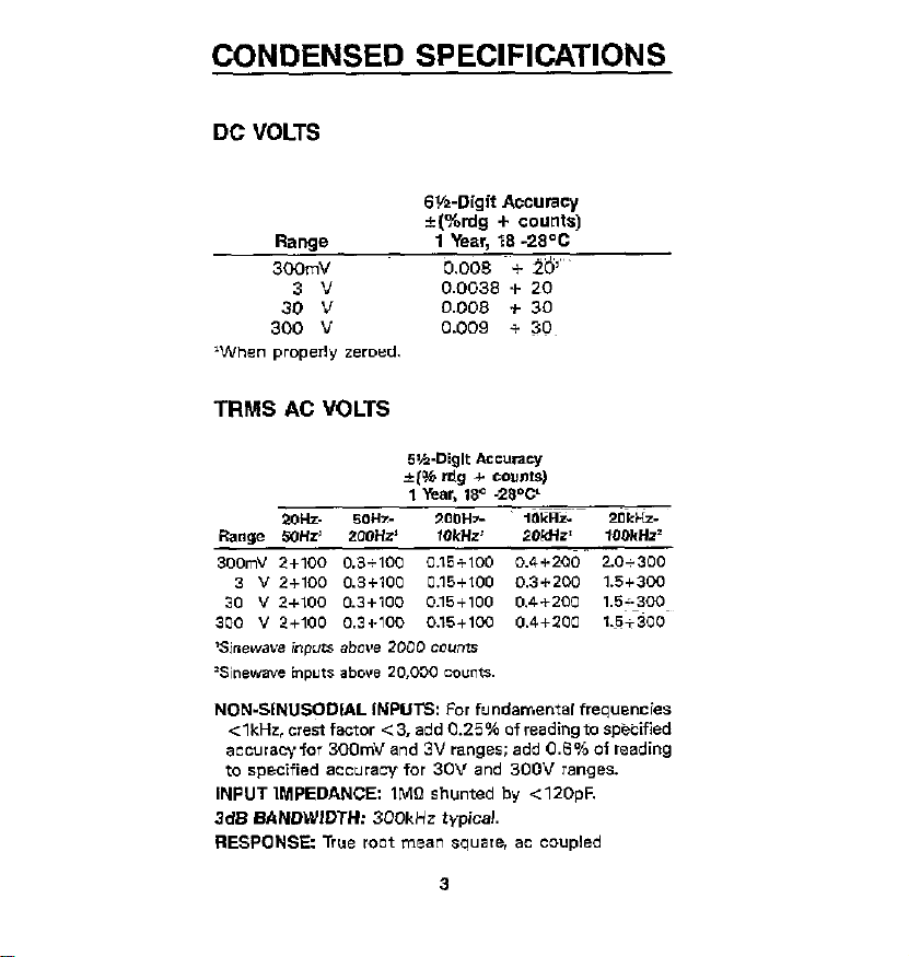
CONDENSED SPECIFICATIONS
DC VOLTS
GH-Digit Accuracy
Range 1 Year, 18 -28~C
300mV
3: “, 0.0038 0.008 * + 20 30
300 V 0.009 $ 30~
‘When properly zeroed.
i(%rdg + counts)
b,00* ~~+ I&’
Page 4
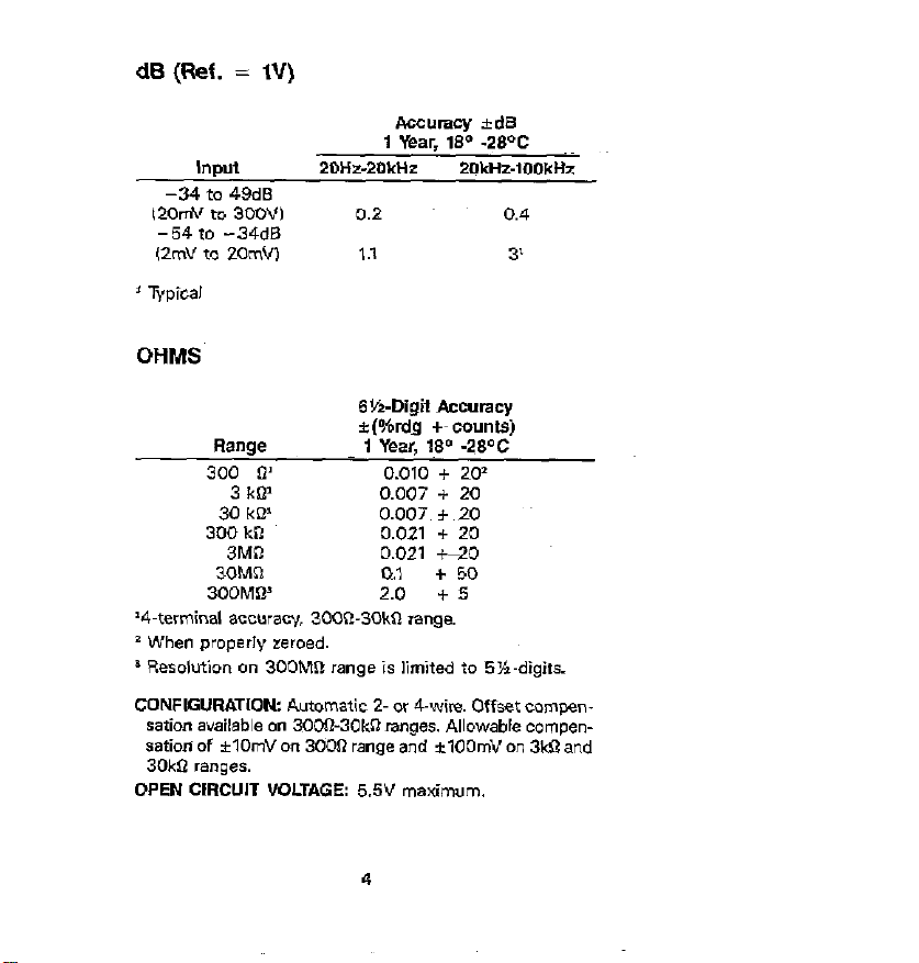
dB (Ref. = IV)
Aecumcy
1 Year, 190 -28cC
Input ZDHz-20kHz 2OkHz-1OOkM
-34 to 49dB
12omv to 3oow 0.2 0.4
- 54 to -34dB
(2mV to zomw 1.1 3’
’ Typical
OHMS
6YeDigti Accuracy
Range
300 0’ 0.010 + 202
3 kQ’ 0.007 + 20
30 kB’ 0.007 f 20
300 kiI 0.021 + 20
3MR 0.021 +-20
30MO 0.1 + 50
3ODMG’ 2.0 + 5
‘4.terminal ?mmacy, 3C!QR-3OkQ range.
z When properly zeroed.
CONFIGURATION: Automatic 2- or 4-wiw. Offset cornpen-
Sation available an 30061-30kfiranges. Allowable compensation of *lOmV on 3OGll range and f100mV on 3m and
3cw ranges.
OPEN CIRCUIT VOLTAGE: 5SV maximum.
+(%rdg +~ counts)
1 Year, 18” -28OC
4
Page 5
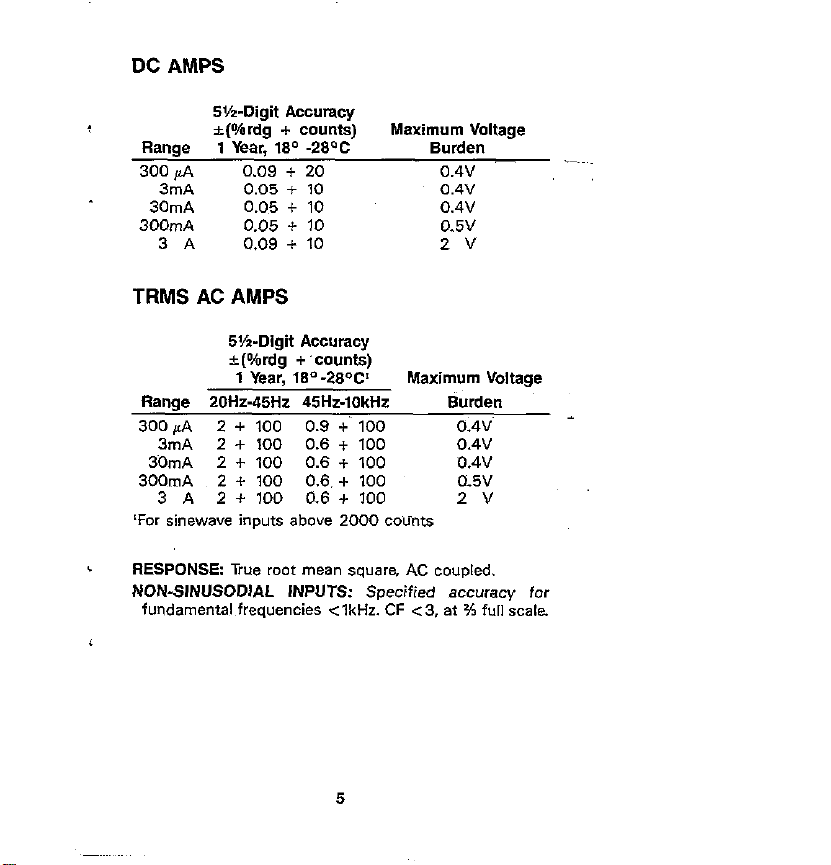
DC AMPS
WeDigit Accuracy
&(#rdg + counts)
1 Year, 180 -29QC
0.09 + 20
0.05 + IO
0.05 + 10
0.05 * 10
0.09 + 10
Maximum Voltage
Burden
0.4v
0.4”
0.4”
0.5v
2v
TRMS AC AMPS
S’h-Digit Accuracy
+wdg +‘counts)
1 Year, w-29W’
Range ZOHz-45Hz 45Hz-1OkHz Burden
300 fi 2 + 100 0.9 +‘~ 100 0.4v
3mA 2 + 100 0.6 + 100 0.4v
30mA 2 + 100 0.6 + 100 D.4V
300mA 2 + 100 0.6. + 100 0.6”
3 A 2 + 100 0.6 + 100 2V
LFor sinewave inputs above 2000 co~ulnts
RESPONSE: True root mean square, AC coupled.
NON-SINUSODIAL INPUTS: Specified accuracy for
fundamental frequencies <lkHz. CF ~3, at K full scale.
Maximum Voltage
5
Page 6
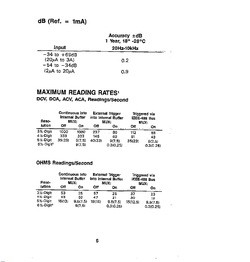
dB (Ref. = 1mA)
Input
-34 to +69dS
(20~A to 3A)
-54 to -34dB
(2pA to 2O,A
Accuracy rdB
1 Year, iSo -28%
ZOHz-IOkHz
0.2
0.9
8
Page 7
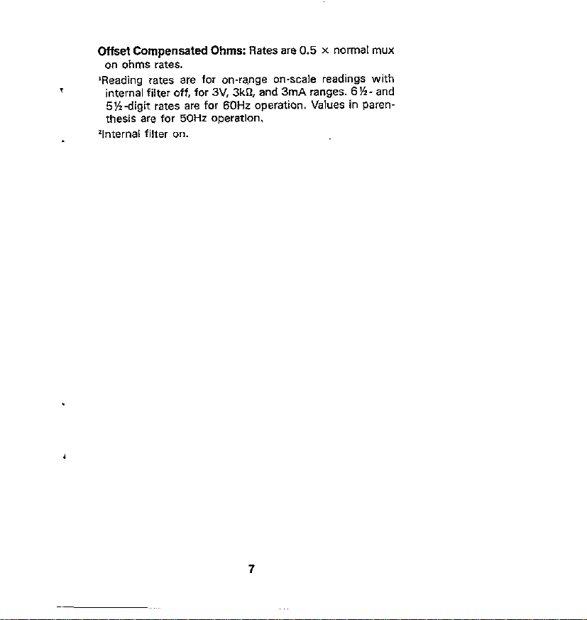
Offset Compensated Ohms: Rates are 0.5 x normal mux
on ohms rate*.
IReading rates are for on-wnge on-scale readings with
internal filter off, for 3V. 3k% and 3mA ranges. 6%. and
5%.digit rates are for 60Hz operation. Values in Paren-
thesis are for 50Hz operation.
‘Internal filfer on.
7
Page 8
SAFETY PRECAUTIONS
Page 9
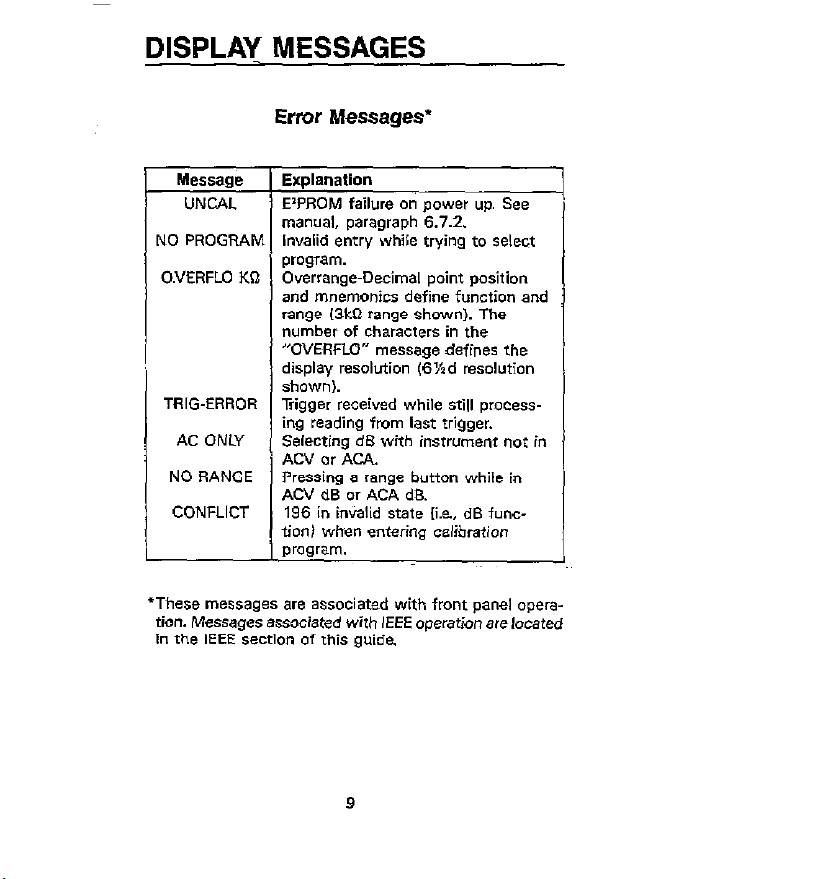
DISPLAY MESSAGES
Error Messages’
E’PROM failure on power up. See
JO PROGRAM Invalid entry while Wing to select [I
O.VERFLO KQ
r
program. -
guide.
Page 10
INPUT SWITCH
10
Page 11
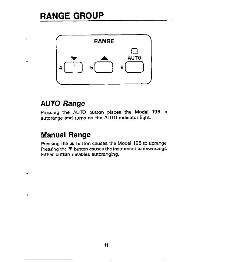
RANGEGROUP
AUTO Range
Pressing the AUTO button places the Model
autorange and turns on the AUTO indicator light.
Manual Range
Pressing the A button CBUSBS the M~odel 196 to uprange.
Pressing the V bunon causes the instrument to downrange.
Either button disables autaranging.
196 in
“.
H
Page 12
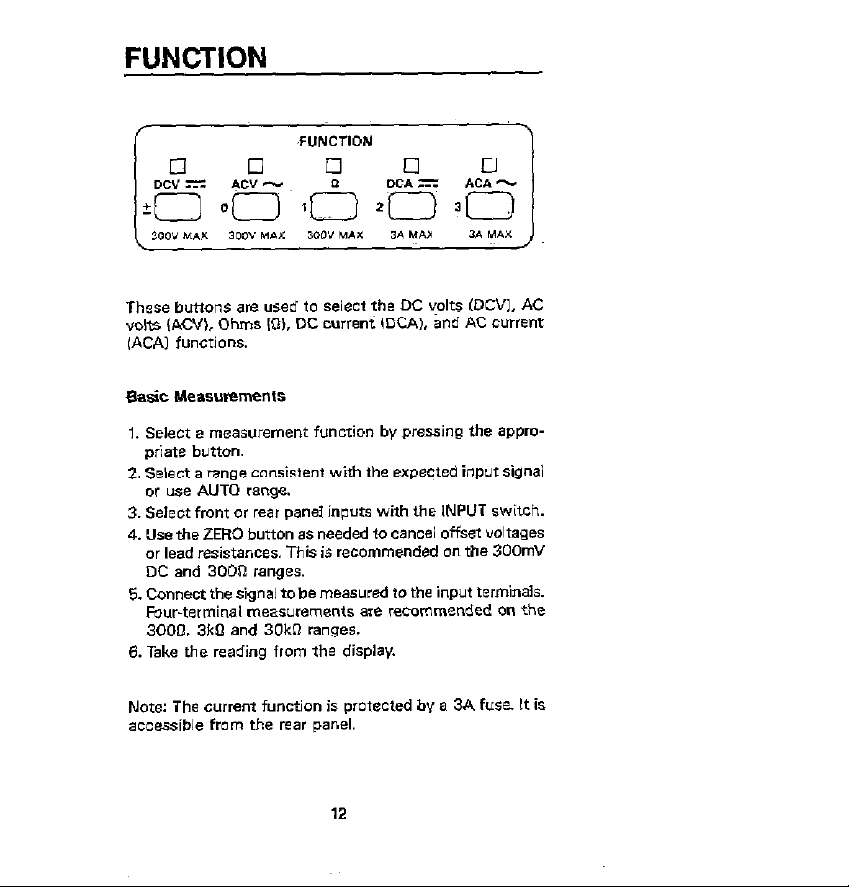
FUNCTION
These buttons are used lo s&c, the DC yolt~ IDCVI, AC
volts iKW, Ohms ID), DC murent IDCA), and AC current
(ACAl functions.
Page 13
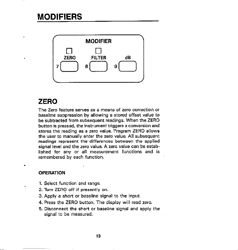
MODIFIERS
c
MODIFIER
)
ZERO
The Zero feature serves as a meam. of zero correction or
baseline suppression by allowing a stored offset value to
be subtracted from subsequent readings. When the ZERO
button is pressed, the instwment triggers a conversion and
stores the reading as a zero value. Program ZERO allows
the we, ,o manually enter the zero value. All subsequent
readings represent the~~differences between the applied
signal level and the zero value A zero value can be established for any or all measurement functions and is
remembered by each function.
OPERATION
1. Select function and range.
2. Turn ZERO off if presently on.
3. Apply a short or baseline signal to the input.
4. Press the ZERO button. The display will read zero.
5. Disconnect the short or baseline signal and apply the
_:___, .^ L^ -^“^.l_^_l
Page 14
Each filtered measurement is first filtered for three time con-
~tant~ before being displayed. A time c(~~stant is measured
in readings. The number of readings in one time constant
is equal to the filter value. Thus, for a filter vakx of 10, three
time constants is equal to 30 readings.
OPERATION
with Program FILTER. set to the desirti filter value and press
the FKTER button. The indicator will turn on and flash
unrii a fully filtered reading is obtained.
dB
The dB button selects the dB measurement mode with the
instrument in the ACV or ACA functions. When measuring
in dB, it is possible to compress a wide range of nwasummenti into a much smaller scope. The displayed reading is
directly in dB. The relationship between dB and voltage/
current can be expressed by the following equations:
dB = 20 log -
lV,I
dB = 20 log -
x.,1
Page 15
where:
Factory Default V,., = 1V
I,,, = 1mA
From the above ewation. it can be derived that 1v or 1rnA
at the input (V,. and IL,) &ill result in a OdB reading on the
Model 196.
There are two methods that can be used to change the
reference value One method is to use the zero feature This
consists of applying a signal to the inslrument and pressing
the ZERO button. The suppressed level is the d6 reference
(DdB point). An alternate method is to use Program d8 to
enter the desired reference value.
OPERATION
Operation consists of selecting ACV Or ACA, changing (if
desired) the dB reference, applying the signal to be
measured, and pressing the dB button.
d9m Measurements:
dBm is decibels above or below a 1mW reference. Measurement in dBm can be referenced to impedance rather than
voltage or current. Because the instrument cannot directly I~
establish impedance references, an equivalent voltage must
be calculated and established for a particular impedance
reference. Use the following equation to calculate the
equivalent voltage:
V,, for OdBm =
J
(1mWb IL.,1
15
Page 16
d&V Measurements:
dBW is decibels above or below a IW reference
Measurements in dBW are made in the same manner as
dBm maasuremen~; lhat is, calculating and establishing
the voltage reference for a pardcular impedance. Use the
following equation to calculate the voltage reference:
V,., for OdBW =
Jz-
16
Page 17
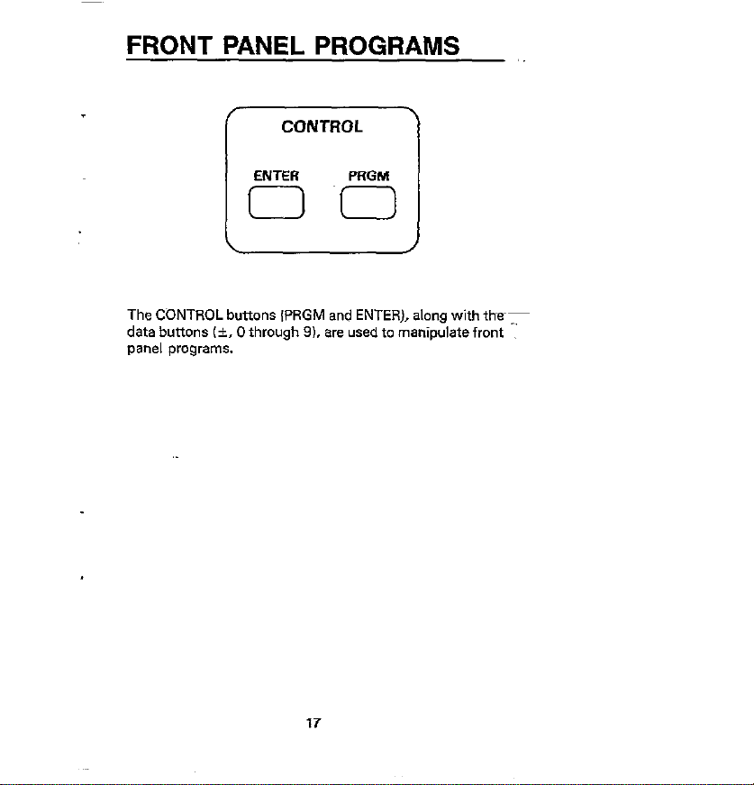
FRONT PANEL PROGRAMS
The CONTROL buttons IPRGM and ENTER), along with thedata buttons (k, 0 through 91. are used to manipulate front
pane, programs.
,,
Page 18

,, ,. ., ~.~ .~.~..
Program
0 (Menui Display sottware level and
2 lResol”tioni Change display resolution
) Description
list available front panel
proQram*.
: (3Kd. 4%d, 6%d or 6Kd,.
! 4 iMX+Bl
5 (Hl/LO/Passi Enable/disable HIIUVPass
6 (Muxl
30 evei Save cUrrent front panel
1 31 (IEEE Address) Recall/modify IEEE address.
Enable MX+B program.
program.
Recall status. enable/disable
avtolcal multiplexer.
setup.
32 Line Frequencyi +xzall/modify line frequenv
33 (Self Test1 Enter self-test program.
34 CMXtB Parametenl Recall/modify MXf6 pro-
satting ~50/6UHzl.
gram “due.
Recall/modify Hi/LO limits.
Enter digital calibration
made.
Returns 196 to factory
default wnditiona.
Recall starus, enable/disable
Program Selection
Page 19

A program can be exited at any time. without changing
previous program parameters, bypressing the PRGM button.
Data Entry
Program data is applied from the front panel using the data
buttons. The data buttons consists of the buttons labelled
with the i polarity sign and numbers 0 through 9. Data
entry is accomplished by pressing the appropriate number
butmn at each cwsor Iocation. Cursor location is indicated
by the bright, flashing display digit. The cursor troves one
digit to the right every time a number is entered.
Program 0 (Menu)
This program displays the software revision level of the
Model 196and lists the available front panel pmgrams. After
the program is selected. use the manual range buttons (V
and A) to scroll through the program listing. To exit from
the menu, press the PRGM button.
Program 2 (Resolution)
This program is used for the selection of the number of digits
of display resolution for the presently selected function.
Available resolution is dependent on function and range.
After the program is selected, display the desired resolu-
tion using the T and A buttons, and then press the ENTER
button.
Program 4 (MX+B)
Program 4 sllows the UQ~, to enable or disable the MX+E
feature. The MX+B feature allows the user to automatically
multiply normal display readings (Xl by a constant IMI and
Page 20

add a constant 181. The result (Yi will be displayed in ac-
cordance with the formula, Y=MX+B. After the program
is selected, any manual range button will toggle the display
to the alternate status. The ENTER button will enter the
displayed status.
Program 5 (HI/LO/Pass)
When this program is selected, the Model 196 will indicate
whether or not a specific reading falls within a prescribed
range. The instrument will display the HI or LO message
for out-of-limit readings and the PASS message for in-limit
readings. The HI and LO limits can be set to any on-range
value with Program 35 (HI/LO Limits). To disable the program. press the presently selected function button.
Program 6 (Auto/Cal Multiplexer)
Program 6 allows the user to disable and enable thee
multiplex circuitry. Wth the multiplexer disabled, measurement speed is increased and high impedance DCV
measurements can be made. After the program is selected.
any range button will toggle the display to the alternate
status. The ENTER button enters the displayed status.
Program 30 (Save)
Program 30 saves the present set up pwxneter. These conditions will replace the previously saved conditions on power
up. After the program is selected, pressing the ENTER button will cause the present set up m be saved. Pressing any
other button will cause the instrument to exit Program 30
without changing the previously saved set up.
.
20
Page 21

Program 31 (IEEE Address)
Program 31 allows the wer to check and/or modify the
IEEE-488 primary address. After Program 31 is selected,
the current IEEE address value will be displayed. To retain
the current IEEE value, press the ENTER button. To change
the Primary address, enter e new vel”e CO to 31) end prees
the ENTER button.
Program 32 (Line Frequency)
Program 32 allows the user to check the line frequency setting of the instrument and to select the alternate frequency
setting. The instrument can be set to either 50 or 60Hz.
After the program is selected, any range button will toggle
the display to the alternate setting. The ENTER button will
enter fhe displayed setting.
Program 33 (Diagnostic)
Program 33 is e diagnostic program designed to switch on
various switching FET’s, relays and logic levels to allow
signal tracing through the instrument. Also, tests on the
display and memory are performed. Refer to paragraph 6.7.3
in the maintenance erection of the manual to use this program to troubleshoot the instrument.
Program 34 (MX+B Parameters)
Program 34 allows the user to check and change the M and
B values for the MX+B feature (Program 41. Valid M values
are in the range of -9.999999 to +9.999999. The B value
range is from z%O.OOOl X10-’ to A9999.999 (including
zero). After Program 34 is selected, the current M velue will
be displayed. To retein the displayed aloe, press the ENTER
2
button. To change the M welue, enteer a “clue and press the
ENTER button. The current B value will then be displayed.
Page 22

To retain the displayed B value, press the ENTER button.
To change the S value, enter a value and press the ENTER
button. Note that the value B is scaled according to the
range in use.
Program 35 (Hi/LO Limits)
This program is used to set the high and low limits for Program 35 CHI/LO/Passl. The limit values are scaled according
to the range in use. When the program is selected, the currently programmed low limit is displayed. Modify the value,
if desired, and press the ENTER button. The high limit will
then be displayed. Modify the high limit, if desired, and press
the ENTER button.
Program 36 (Calibration)
The user can easily perfotm front panel digital calibration
by applying accurate calibration signals and using Program
36. Calibration signals can be prompted default values or
values entered from the front panel. Refer to the Model 196
Instruction Manual, Section 6 for complete information.
Program 37 (Reset)
Program 37 resets all instrument Set up parameters back
to the factory default conditions. After the program is
s&cIed, pressing Ihe ENTER button will reset the instrument to factory default conditions. Pressing any other button will cause the instrument to exit Program 37 without
resetting the parameters. After running this program. Program 30 must be run to have factory default conditions on
power up.
22
Page 23

Program il
OhIns compensation is USed t0 compensate for external
voltage potential* *cm** the unknown resistor when
making 2 or &terminal resistance mea*UrementS up to
3oOkS2 After Ihis program is selected, any range button will
toggle the display to the alternate *tafu* (on/offL The ENTER
button enter* the displayed *tafus. With ohms compensation enabled. the n indicator light will blink when the ohms
function is selected.
Program ZERO
Program ZERO allow* the user to check and modify the zero
value After Program ZERO is selected the current zero value
will be displayed. If desired, change the displayed zero value
and press the ENTER button. The instrument will return to
the previous operating *tare with the zero modifier enabled.
The subsequent displayed reading will reflect the entered
zero Y*lu*.
Program FILTER
Program FILTER allows the u.ser to check and modify the
number of readings averaged by the filter. After the program
is selected the current filter value will be displayed. Alter
me filter value, if desired. and pre*s the ENTER button. The
instrument will retllrn to the previous operating State witi
the filter enabled u*ing the programmed filter value.
Program dB
This program allow* the user to check and!or change the
dB reference level. When this program is selected. the currently programmed reference level will be displayed. Alter
the reference level, if desired. andpress the ENTER button.
The referenca range for ACV is up to 9.9999~9V and the
’ range for current is up to 9.99999mA.
23
”
Page 24

LOCAL
/TLK RMT LSN
ICI n q
LOCAL
cl
The LOCAL button allmm the user to return control to the
front panel when the instrument is being controlled over
the lEEE-488 bus IRMTindicator lightanl. This button twil,
have no effect if local lockout ILL01 was asserted over the
bus.
24
Page 25

FRONT PANEL TRIGGERING
For frcmt panel triggering, the instrument must be placed
in the appropriate trigger mode from over the IEEE-488 bus.
One-shot Triggering:
1. Select function and range.
2. Place the instrument in the one-shot trigger mode by
sending the T7 command over the bus.
3. Press the LOCAL butto” to return control to the front
pane,.
4. Each press of the ENTER button will trigger a reading.
Triggering Readings Into Data Store:
1. Select function and range.
2. Place the instrument in the appropriate trigger mode:
A. Send T7 (one-shot) over the bus if each press of the
ENTER button is to Store one reading in the buffer.
B. Send T6 (continuous) over the bus if the ENTER but-
ton is to star? storage of a series of readings into the
buffer.
3. Configure the data store by sending the appropriate Qn
(interval) and I (size) commands over the bus.
4. Press the LOCAL button to return control to the front
pane,.
.
5. Press the ENTER button to either store one reading or
start storage of a series of readings.
25
Page 26

EXTERNAL TRIGGERING
The Model 196 has two external BNC connectors on the
rear panel associared with instrumenf triggering. The EXTERNAL TRIGGER lNPUT allows the instrument u) be triggered by other devices, while VOLTMETER COMPLETE
OUTPUT allows the instrllment to trigger oriler devices.
External Trigger Input
1. Set the Model 196 fo the oneshot external trigger mode
IT71 or the continuous external trigger made (T-51.
2. Input an appropriate trigger pulse source bee FIG 11 to
the EXTERNAL TRIGGER INPUT.
3. The in&nnent will process a single reading each time
a pulse is applied ione-shotl. or start a continuous series
of readings
FIG 7. External Trigger Pulse Specilications
26
Page 27

Voltmeter Complete Output
The voltmeter complete pulse (see FIG 21 signifies completion of the measuemem cycle The voltmeter complete line
can be used to trigger another instrument or to inform an
instrument that the mea*uremenr has teen complered.
1. Connect the VOLTMETER COMPLETE OUTPbT 01 the
Model 196 to the external trigger input of another
instrument.
2. In a continuous trigger mode, the instrument will outpur
pukes at the conversion rate; each pulse will occur after
the Model 196 has completed B conver.sion.
3. In a one-shot trigger mode, the Model 196 will output
a puke once each lime it is triggered.
FIG 2. Voltmeter Complete Pulse Speciffcaiion
Page 28

IEEE-488 PROGRAMMING
This section briefly describes Model 196 operation over
IEEE488 bus. All device-dependent commands are listed.
More derailed information and programming examples are
listed in the Model 196 instruction Manual.
_~>~_.““i.._.
,,,.,,, ..,,, ,,,”
mecute
X = Execute other device-dependent com(nayds.
Function
FD = DC “Oks
Ft = AC “olts
FZ = Ohms
F3 = DC cwrent
F4 = AC current
F5 = ACV dB
F6 = ACA dB
F7 = Offset compensated ohms :
Range
Dcv
RO = A”to
R1 = 3OOmV
R2= 3v
R3 = 30 ”
al = 300 v
~R5 = 300 V
R6 = 300 V
R7 = 300 v 300 V 3 A
Acv
AIltO
300mV
3V
30mV
300 ”
300 v
300 V
,~ ,.,,
PC4 ,,
Auto
300 pA
3rnA
30mA 30mA
3OOmA 300mA
3A
3A
3A
3A
3A
~,~,. I
28
Page 29

Range (cont.)
offset
Compensated
Ohms
RO = Auto
Rf = 300 a
R2 = 3 klI
R3 = 30 kG
R4 = 300 kfl
R5 =
RS = 30Mn
R7 = 300MO
PO = Filter disabled
Pn = Filter on with a value of n Ln = 1 to 99)
3MO
AC’, dB ACA dB
Auto AUtO
.4”utO
A”to
Auto AlltO
AlIt0
Allto
Auto A”to
A”fo
Au*0 ~300 a
A”tO 3 k%I
Auto 30 kO
A”to 30 kfl
A”to 30 klI
Ohms
ALIt0
30 kQ
30 kO
29
Page 30

_.~:.._
%d,Rl-R4l 5’/id
%dlR5-R71
YzdWWW 5Xd
5%dW-R7J
S2 = 5Md
S3 = WM’;p”’ 5Kd
! Integration period: 3%d=31Spec, 4Kd=2Sgmsec,
1 5%d and G%d=Line cycle
5%d
5x*
5’hd
5%d
5%d
5yzd
5Xd
5%d
6%d
lklgger Mode
TO = Continuous on I-&
Tl = One-shot on Taik
TZ = Continuous on GET
T3 = One-shot on GET
T4 = Continuous on X
T5 = One.shot on X
T6 = Continuous on External Eigger
T7 = One-shot an External Trigger
1
,.,
Reading Mode
80 = Readings from AiD converter
BT = Readings from data store
Oata Store Size
IO = Continuous data store mode
In = Data *tore Of n h= I to 500)
30
,,.
,,.,, ,, ~~ .~,
,, : ,,.
Page 31

Calibration
CO = Calibrates first point using value WI
Cl = Calibrate second wint using value IV1
Default Conditions
LO =~~ Restore factory default conditions.
Ll = Store present machine status as default
conditions
I
Data Format
GO = Reading with prefixes.
Gl = Reading without prefixes.
G2 = Buffer readings with prefixes and buffer
f
*
locations.
G3 = Buffer readings without prefixes and with bof-
fer locations.
G4 = Buffer readings with prefixes and without buf-
fer locations.
G5 = Buffer readings without prefixes and without
buffer locations.
31
I
Page 32

SRQ
MO = Disable
Ml = Reading overflow
M2 = Data state full
An4 = Data store halt full
MS = Reading done
Iv?16 = Ready
M32 = Error
KO = Enable EOI and bus hold-off on X
Kl = Disable EOI. enable bus hold-off on X
K2 = Enable EOI, disable bus hold-off on X
K3 = Disable both EOI and bus hold-off on X
.,,,,.,,,, i” ,,,,,,.,: .,,,...., ,:,,
Terminator
YO = CR LF
Yl = LF CR
Y2 = CR
Y3 = LF
UO = Send machine starus word
Ul = Send error conditions
U2 = Send Translator word
“3 = Send buffer size
U4 = Send average reading in buffer
U5 = Send lowest reading in buffer
U6 = Send highest reading in buffer
Vi’ = Send cwient value
U8 = Send input switch status Wronthaarl
32
Page 33

A0 = Auto/Cal Multiplexer disabled
Al = Auto/Cal Multiplexer enabled
Wn = n=delay period in milliseconds, (Omsec to
60000msec)
Self-test
JO = Test. ROM, RAM, E’PROM
Hn = Hit front panel button number n
Da = Display up to 10 character message
Internal Filter
NO = Internal filter off
Nl = fntemal filter on
33
,.,,.., .,~..
Page 34

Mode
Multiplex
Reading
Funcrion
Data Format GO
Self-test
EOI
SR(1
Internal Filter Nl
Digital Filter
Data Store Interval
Data Store Size I1
Range R4
Rate s3
Trigger T6
Commfll j Status
Al I Enabled~
SO
FO
JO
KO
MO
PO
QO
,, ~~1.
A/D mnwmer
DC Volts
Send prefix with
reading
Clear
Enable EOI and bus
hold-off on X
Disabled
One-shot into buffer
Depends on function
Depends on function
_
34
Page 35

BUS ERROR MESSAGES
.,
Message
NO REMOTE ) instrument programmed with REN
/ Description
lDDC
IDDCO
TRIG ERROR
SHOW TIME
SIG STRING
CAL LOCKED
CONFLICT
illegal Device-deqendent Commaod
Illegal Device-dependent Command
Option
instrument triggered while it is still
processing a previous trigger.
Instrument cannot store readings at
programmed interval. Readings will
be stored as fast as the instrument
can W”.
Programmed display message exceeds 10 characters.
Calibration command sent with
calibration switch in the disable
position.
Data storage--l”str”ment cannot
store readings at a high speed interval II to 14msect while in an invalid
state Storage will not OCC”,.
Calibration-Calibration command is
ignored when instrument is in an invalid state lie., dS functionl.
35
Page 36

b:
OCV=DC VOLT,S
ACV=AC VOLTS
OHM=OWlS
oCI=oC AMPS
ACI-AC AMPS,
dBV=AC dB VOLTS
dEI=AC dB AMPS
‘NONE = DATA STORE EMPTY
Page 37

SERIAL POLL BYTE
(Status Byte)
Page 38

MACHINE STATUS (“0)
STATUS WORDS
I I
Page 39

ERROR STATUS (01)
Page 40

TRANSLATOR SOFTWARE
RESERVED WORDS AND CHARACTERS
WordlCharacterl Description
ALIAS
$
NEW
OLD
SAVE
LIST
FORGET
The basic format for defining a Xanslator word is shown
in the following example command string, which defines
the word SETUP 1 as a substitute for FIROX.
Used at the beginning of a command String to define Translator
words.
Used to terminate the Translator
string (one space must precede it).
Used to define wild card Translator
words. Values sent with a wild
card Translator word select options
of the equivalent DDC.
Tells the Model 196 to recognize
Translator words.
Tells the Model 1% to only
recognize the Keithley devicedependent commands.
Saves Translator words as power
up default.
Used to list the Translator words.
Used to purge Translator words
from memorv.
“ALIAS SETUP, FlROX ;”
40
Page 41

WILD CARD ($) TRANSLATOR WORD5
By using the reserved character 5. the same basic Translator
word can be used to select all cations of a command. With
this feature. a DDC option number is sent with the lianslator
word. The following example shows the format for defining a wild card Translator word:
‘ALIAS FUNCTION FSX ;”
In the example, the wild card Translatm word FUNCTION
replaces the F command. Instrument functions are selected
by sending the FUNCTION command with the appropriate
option number over the bus.
COMBINING TRANSLATOR WORDS
The format for combining Translator words to form a new
Translator word is shown in the following example, which
combines the words SETUP1 and SETUP2 to form the
Translator word SETUP3.
“ALIAS SETUP3 NEW SETUP1 NEW SETUP.2 ;”
COMBINING TRANSLATOR WORDS WITH KEITHLEY
IEEE-488 COMMANDS
The format for combining a Translator word with Keithley
IEEE commands is shown in the following example, which
combines the Translator word SETUP1 with the Keithley
command string PlZlX to form the Translator word SETUP4.
‘ALIAS SETUP4 NEW SETUP1 PlZlX ;))
41
Page 42

EXECUTING TRANSLATOR WORDS AND KEITHLEY
COMMANDS
Translator words can only be executed with the instrument
in the NEW mode. Sending the reserved word NEW over
the bus places the instrument in the NEW mode. The for-
mats for placing the instrument in the NEW made and for
executing the Translator word SETUPl, is shown as follows:
“NEW”
“SETUPI”
The reserved word ALIAS automatically puts the instrument
in the NEW mode.
Sending wild card Translator words over the bus is as
follows:
“NEW”
“FUNCTION 1”
With FUNCTION being the wild card Translator word for the
F command, the second statement will place the instrument
in the ACV function IFl). Notice that a space must be included between the wild card Translator word the option
number.
Translator words and Keithley IEEE commands can be et+
ecuted in the same command string. The following example executes the commands of SETUP, and PlZ,X.
“SETUP1 PlZlX”
42
Page 43

When executing a Xanslator word that was formed from
the combination of two or more wild card Translator Words,
a” option “umber se”? with the word will only apply to the
first wild card word in the combined string. For example,
assume the Translator word TEST was formed from the
combination of the wild card Translqtor words FUNCTION
and RANGE as show”:
“ALIAS TEST NEW FUNCTION NEW RANGE :”
Sending TEST 1 over the bus will place the instrument in
ACV (Fll. RANGE will default to 0 kwtorangel.
43
Page 44

Translator Error Messages
Display
“^^^^__ C”..l_.._.l__ C___I_ c_-_ ^._/__
Page 45

PROGRAMS
The following programs are designed to be a simple aid to
the user. They are not intended to suit specific needs. Detailed programming information can be found in the manual.
The fint program demonstrates how to store and read the
contents of the buffer (data store) using the HP-85 computer. One hundred readings stored in the buffer will be
displayed,
The rest of the programs display one reading at the output
of the controller. Each program provides an ASCII string
variable outp”t of the form:
NDC” f O.OOOOOOE + 0 CR LF
The note et the end of some programs indicates modifications to provide a numeric variable in exponential form:
*O.o00000E + 0
45
Page 46

DATA STORE OPERATION
USING HP-85
The following program will enable data store (buffer) operation and obtain and display 100 readings on the computer
CRT
DIRECTIONS
1. Using front panel Program 31, set the primary address
on the Model 196 to 7.
2. Connect the Model 196tothe HP82937A IEEEinterface.
3. Enter the following program using the END LINE key after
each line is typed.
4. Press the HP-85 run key. The program will enable the~buffer. turn on the buffer ~“tput, and request and display
100 readings.
PROGRAM
FJ.MMENTs ,.,
Send remote enable
Set trigger mode, and
&rage parameters.
start storage process.
Set read mode to data
store
set CO”rlter for 100 loops
Get a reading.
Display reading.
Loop back for next reading.
46
Page 47

IBM PC or XT
(Keithley Model 8573A Interface)
The following program sends a command string to the
Model 196 from an IBM PC or XT computer and displays
the instrument reading string an the CRT The computer
must be equipped with the Keithley Model 957% IEEE-486
interface and the DOS 2.00 operating system. Model
S573A software must be installed and configured as
described in the instruction manual.
DIRECTIONS
1. Using the front panel program feature, set the primary
address of the Model 196 to 7.
2 With the power off, connect the Model 196 to the
IEEE-488 interface installed in the IBM computer.
3. Type in BASICA on the computer keyboard to get into
the IBM interpretive BASIC language
4. Place the interface software disk in the default drive, type
1OAD”DECC: and press the return key.
5. Add the lines below to line l-6 which are now in memory.
Modify the address in lines 1 and 2, as described in the
Model B573A Instruction Manual.
6. Run the program and type in the desired command string.
For example, to place the instrument in the ACV function and autorange. type in FlROX and press the return
key.
7. The instrument reading string will then appear on the
display. For example. the display might show
NDCV+O.OOWlOOE+O.
9. To exit the~program. type in EXIT at the command prompt
and press the return key.
47
Page 48

PROGRAM COMMENTS
Set REN true.
Prompt for command.
See if program is to be
halted.
Check for null input.
Address 196 to listen, send
srnng.
Define reading input buffer.
48
Page 49

APPLE II
(APPLE II IEEE-488 Interface)
The following program sends a command string to the
Model 196 from an Apple II computer and displays the instrument reading string on the computer CRT,
The compufer must be equipped with the Apple II IEEE-488
interface installed in slot 3.
DIRECTIONS
1. Using the front panel program feature, set the primary
address of the Model 196 to 7.
2. With the power off. connect the Model 196 to the
IEEE-488 interface installed in the Apple II computer.
3. Enter the lines in the program below. using the RETURN
key after each line
4. Run the program and type in the desired command string
at the command prompt. For example, to place the in-
strument in ACV and autorange. type in FIROX and press
the return key.
5. The instrument reading string will then appear on the
CRT. A typical display is: NDCV+O.OOOOOOE+O.
49
Page 50

PROGRAM
1. If conversion to numedc variable is required, make the
following changes:
2. The Apple II terminates on commas in the data string.
To avoid problems. program the Model 196 for the BOG0
or BOG1 data format to eliminate commas.
COMMENTS
Terminator
Prompt for and enter
command string.
Set output to IEEE-488 bus.
Define input fmm IEEE-488
b”S.
Enable remote.
Addreis 196 to listen, send
string.
Line feed on.
Address 196 to talk, input
data.
Untalk the 196.
Define ourput to CRT.
Define input from keyboard.
Display reading string.
_
-.-
50
Page 51

HP-85
The following program sends a command string to the
Model 196 from an HP-65 computer and displays the instrument reading on the computer CRT;The computer mwt
be equipped with the HP82937 GPIB interface and an l/O
ROM.
DIRECTIONS
1. Using the front panel program feature, set the primary
address of the Model 1% to 7.
2. With the power off, connect the Model 196 to the
HP62937A GPIB interface installed in the HP-65
computer.
3. Enter the lines in the program below. using the END LINE
key after each line.
4. Press the HP-85 RUN key and type in the desired command string at the command prompt. For example, to
~place the insrrumenr in AC” and autorange, type in
FlROX and press the END LINE key.
6. The instrument reading string will then appear on the
CRT. A typical display is: NDCV+O.OOOOOOE+0.
51
Page 52

PROGRAM
NOTE: for conversion to numeric variable, change line 70
as follows:
COMMENTS ‘.~
52
Page 53

HP-9816
The following program sends a command string to the
Model 196 from a HP-9816 computer and displays the instrument readina strinp on the comwter CRT. The computer must be &p&with the HP62937 GPIB interface
and BASIC 2.0.
DIRECTIONS
1. Using the front panel program feature, set the primary
address of the Model 196 to 7.
2. With the power off, connect the Model 196 to the
HP82937A GPIB interface installed in the 9816 computer.
3. Type EDIT and press the EXEC key.
4. Enter the lines in the program below, using the ENTER
key after each line.
5. Press the 9816 RUN key and type in the desired command string at the command prompt. For example, to
place the instrument in ACV and autqrange, type in
FlROX and press the ENTER key.
6. The instrument reading string will then appear on the
CRT. A typical display is NDCV+O.OOOOOOE+O.
53
Page 54

PROGRAM
CWMEWS ,, ..,,., ,,.. .,,
54
Page 55

HP-9825A
Use the following program to send a command string to
the Model 196 from a HP-9825A and display the in*tru-
ment reading string on the computer printer. The cornpurer
must be equipped with theHP98034A GP18 interface and
a 9872A extended I/O ROM.
DIRECTIONS
1. From the front panel, set rhe primary address of the Model
196 to 7.
2.With the power off, connect the Model 196 to the
99034A HPIB interface installed in the 9825A.
3.Enter the lines in the program below, using the STORE
key after each line. Line numbers are automatically
assigned by the 9825A.
4.Press the 9925A RUN key and type in the desired command string at the command prompt. For example, to
place the instrument in AC%! and autorange, type in FIROX
and press the CONT key.
5.The instrument reading string will then appear on the
computer print out. A typical display is:
NDCV+O.OOOOOOE+O.
55
Page 56

PROGRAM
6 PRTIM
7 GTO3
COf+ZNTS
,,,
string.
Address 196 to listen, send
string.
Address 196 to talk, input
data.
Print data string on printer.
Repeat.
56
Page 57

DEC LSI 11
The following program sends a command string *o the
Model 196 from a DEC LSI 11 minicomputer and displays
the instrument reading string on the DEC CRT terminal. The
LSI 11 mwt be configured with 16K words orRAM and an
IBV 11 IEEE-488 interface. The software must be configured
with the IB software as well as FORTRAN and the RT 11
operating system.
DIRECTIONS
1. Using the front panel program feature, set the primary
address of the Model 196 to 7.
2.With the power off, connect the Model 196 to the IBV
11 IEEE-488 interface cable.
3.Enter the program below. using the editor under RT 11
and the name IEEEFOR.
4.Compile using the FORTRAN compiler as follows:
FORTRAN IEEE.
S.Link with the system and IB libraries as fallows: LINK
IEEE,IBLIB.
&Type RUN IEEE and press the RETURN key.
7.The display will read “ENTER ADDRESS’!
8.Type in 7 and press the RETURN key.
S.The display will read “TEST SETUP’:
lO.Twe in the desired command strina and mess the
RETURN key. For example, to program the i&trument
for ACV and autorange, type in FlROX and press
RETURN.
11. The instrument data string will appear on the computer
display. A typical display is: NDCV+O.OOOOOO+E.
57
Page 58

58
Prompt for command string.
Program
instrument.
Address 196 to
listen. send
string.
Get data from
Untalk the 196,
Repeat.
Page 59

PET/CBM 2001
The following program sends command strings to the Model
196 from a PETKBM 2001 computer and displays the in.
strument reading string on the computer CRT. As the
PEVCEM computer has a standard IEEE-486 interface, no
additional equipment is necessary.
DIRECTIONS
1. Using the from panel program feature, set the primary
address of the Model 196 to 7.
2. With the power off. connect the Model 196 to the
PET,CBM IEEE-488 interface.
3. Enter the lines of tha program below, using theRETURN
key after each line is typed.
4. Type RUN and ~press the RETURN key. Type in the desired
command string at the command prompt. For example,
to place the instrument in ACV and autorange, type in
FIROX and press the RETURN key.
6. The instrument reading string will then appear on the
CRT. A typical display is: NDCV+O.O00000+EO.
59
Page 60

PROGRAM COMMENTS
Open file 1. primary ad-
20 INPU~“CONEl*NDSTRING’ 7 Prompt for input corn-
iBI “and string.
~BPEI~T#I,BI;
43 IHPIIT#1,RB
50 IF ST=2 MEN 413 If bus timeout, input
60 PRINTCII
78 GOT0 29
NOTES:
1. If conversion to numeric variable is required, modify the
2. The PET terminates on commas in the data string. To
avoid problems, program the Model 196 for the BOG0 or
BOG1 data format TO eliminate commas.
dress 7.
Address 196 to listen.
Send string.
Address 196 to tak, input data.
again.
Display reading string.
,,RePeat.~ ,,,
.,
60
 Loading...