

Page 1
Model 195T
System Temperature DMM
Instruction Manual Supplement
Document Number: 195T-90%OIA
Publication Date: February 1993
.
Page 2
WARRANTY
We warrant each of our products to be free from defects in material
and workmanship. Our obligation under this warranty is to repair
or replace any instrument or part thereof which, within a year after
shipment, proves defective upcn examination. We will pay local
domestic surface freight costs.
To exercise this warranty, write or call your local Keithley repre-
sentative, or contact Keithley headquarters in Cleveland, Ohio.
You will be given prompt assistance and shipping instructions.
REPAIRS AND
CALIBRATION
Keithley Instruments maintains a complete repair and calibration
service as well as a standards laboratory in Cleveland, Ohio.
A Keithley service facility at our Munich, Germany office is
available for our customers throughout Europe. Service in the
United Kingdom can be handled at our office in Reading. Additionally, Keithley representatives in most countries maintain service
and calibration facilities.
To insure prompt repair or recalibration service, please contact
your local field representative or Keithley headquarters directly
before returning the instrument. Estimates for repairs, normal
recalibrations and calibrations traceable to the National Bureau of
Standards are available upon request.
Keithley Instruments, Inc.128775 Aurora Road/Cleveland, Ohio 44139/U.S.A./(216) 246-0400/Telex: 965469
WEST GERMANY: Ksithley Instruments GmbHlHeiglhofstrasse 5/O-8000 MUnchen 7O/lO691 7144&65/Telex: 521 21 60
GREAT BRITAIN: Keithley Instruments. Ltd./l, Boulton Road/Reading, Berkshire RG2 ONL/i07341 66 12 B7lTelex: 647047
FRANCE: Kefthley Instrumenta SAALl2 Bis, Rue Ldon Blum1B.P. 60/91121 Palaiseau Cedex/~61011.51.55/Telex: 600933F
NETHERLANDS: Keithley Instrument8 BVlArkelsedijk 4/NL-4206 AC Gorinchem/i016301 25577/T&x: 24 664
SWITZERLAND: Kelthley Instruments SAIKriasbachstr. 4/CH-6600 OUbendorf/Ol 621 94 44/T&x: 57 536
AUSTRIA: Kslthley instruments Ges.m.b.H./OOblinger Hauptstr. 32/A-1190 Wien/0222 314 2BS/Telex: 13 45 00
Page 3
Model 195T
System Temperature DMM
Instruction Manual Supplement
01983, Keithley Instruments, Inc.
Cleveland, Ohio, U.S.A.
Page 4
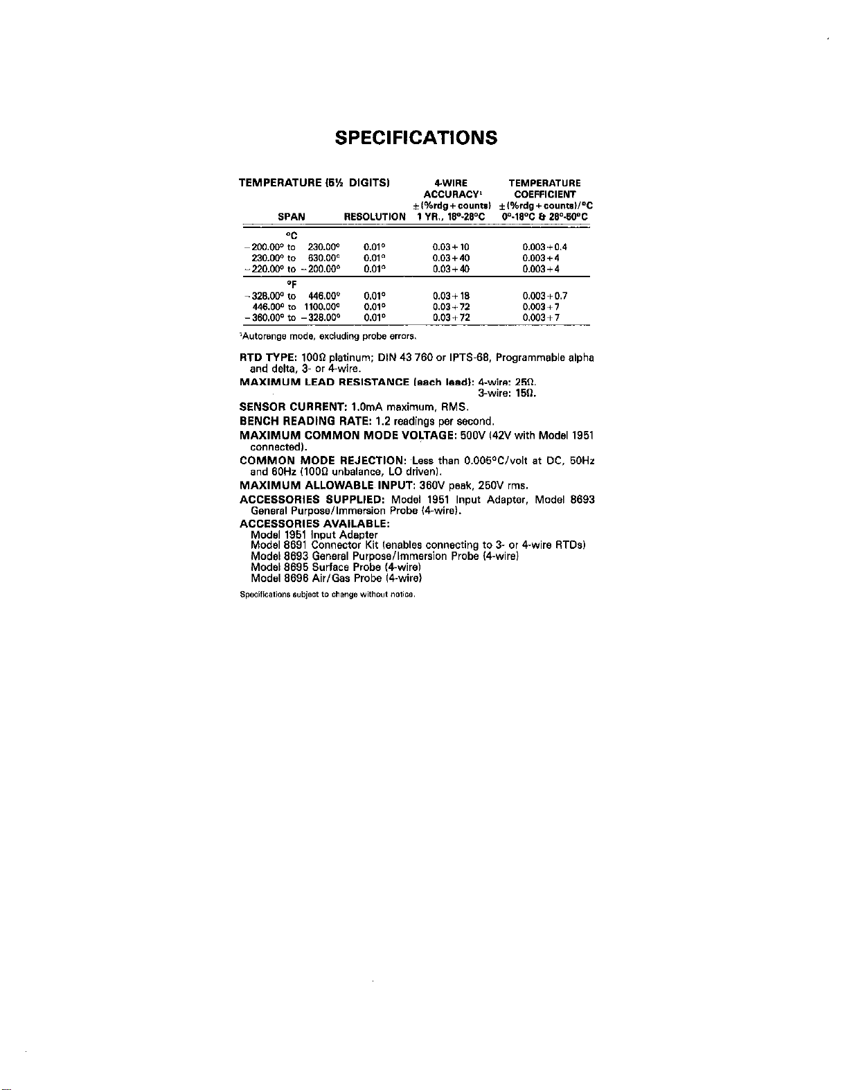
SPECIFICATIONS
RTD TYPE: lOO* platinum; DIN 43 760 or IPTS-SB, Programmable alpha
and delta, 3. or 4.wire.
MAXIMUM LEAD REBlBTANCE leach lead): 4.wire: 250.
SENSOR CURRENT: l.OmA maximum. RMS.
BENCH READING RATE: 1.2 readings per second.
MAXIMUM COMMON MODE VOLTAGE: 500V 142V with Mod81 1951
connected,.
COMMON MODE REJECTION: ,Less than 0.005°C/volt at DC, 50Hz
and 60Hz (1000 unbalance, LO drivenl.
MAXIMUM ALLOWABLE INPUT: 360V peak. 250V rms.
ACCESSORIES SUPPLIED: Model 1951’ lnp~t Adapter. Model 9693
General Purpose/Immersion Probe l4wire).
ACCESSORIES AVAILABLE:
Model 1961 Input Adapter
Model 8991 Connector Kit (enables connecting to 3. or 4.wire RTDs)
Model 9993 Gensral Purpose/Immersion Probe ICwirel
Model 9695 Surface Probe kvirel
Model 9696 Air/Gas Probe ICwirel
S-wire: 150.
Page 5
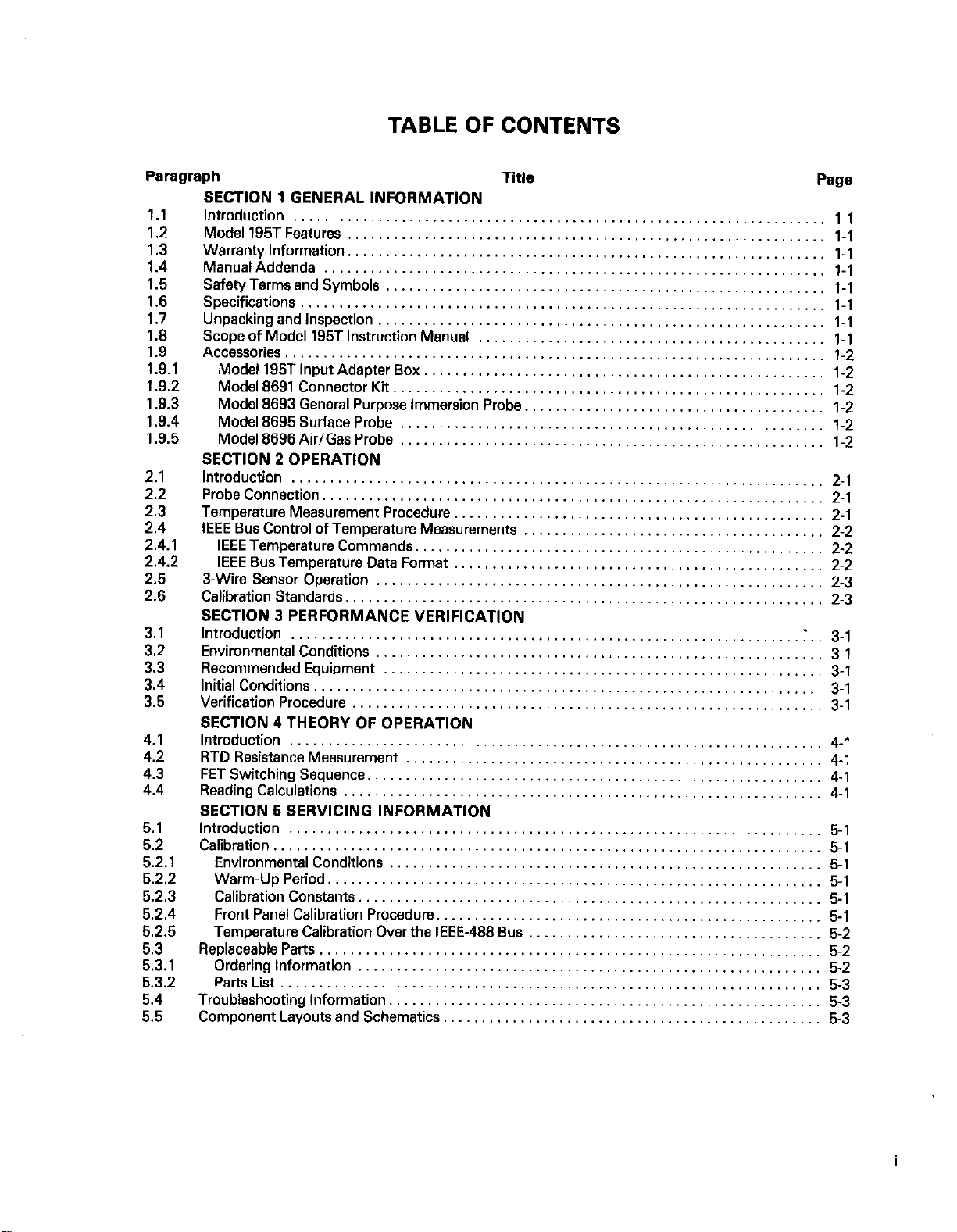
TABLE OF CONTENTS
Paragraph
1.1
1.2
1.3
1.4
1.5
1.6
1.7
1.8
1.9
1.9.1
1.9.2
1 Al.3
1.9.4
1.9.5
2.1
2.2
2.3
2.4
2.4.1
2.4.2
2.5
2.6
3.1
3.2
3.3
3.4
3.5
4.1
4.2
4.3
4.4
5.1
5.2
5.2.1
5.2.2
5.2.3
5.2.4
5.2.5
5.3
5.3.1
5.3.2
5.4
5.5
Title
SECTION 1 GENERAL INFORMATION
Introduction .....................................................................
Modell95TFeatures ..............................................................
Warranty Information.
.............................................................
ManualAddenda .................................................................
Safety Terms and Symbols
..................
......................................
PalIe
l-l
l-l
1-l
1-l
l-l
Specifications .................................................................... l-l
Unpackingandlnspection
..........................................................
Scope of Model 195T Instruction Manual
.............................................
l-l
l-l
Accessories ...................................................................... l-2
Model 195T Input Adapter Box.
...................................................
Model669lConnectorKit ........................................................
Model 8693 General Purpose Immersion Probe.
......................................
Modal6695SurfaceProbe .......................................................
Model 6696 Air/Gas Probe
SECTION 2 OPERATION
.......................................................
l-2
1-2
1.2
1-2
l-2
Introduction ..................................................................... 2-l
ProbeConnection .................................................................
Temperature Measurement Procedure.
IEEE Bus Control of Temperature Measurements
IEEE Temperature Commands.
IEEE Bus Temperature Data Format
3-Wire Sensor Operation
..........................................................
...............................................
.......................................
....................................................
................................................
2-1
2-l
2.2
2-2
2-2
2-3
Calibrationstandards .............................................................. 2-3
SECTION 3 PERFORMANCE VERIFICATION
Introduction
Environmental Conditions
RecommendedEquipment
Initial Conditions
Verification Procedure
SECTION 4 THEORY OF OPERATION
..................................................................
..........................................................
.........................................................
..................................................................
.............................................................
Introduction .....................................................................
RTD Resistance Measurement
......................................................
:. 3-l
3-l
3-l
3-l
3-l
4-l
4-l
FETSwitching Sequence ........................................................... 4-l
ReadingCalculations.. ............................................................
SECTION 5 SERVICING INFORMATION
Introduction .....................................................................
Canbra6on .......................................................................
Environmental Conditions
........................................................
Warm-UpPeriod ................................................................
Calibration Constants.
Front Panel Calibration Prqcedure.
Temperature Calibration Over the IEEE-466 Bus
...........................................................
.................................................
...................................... 5-2
ReplaceableParts .................................................................
Ordering Information
Parts List
......................................................................
Troubleshooting Information
Component Layouts and Schematics.
............................................................
........................................................
................................................
4-l
5-l
5-l
5-l
5-l
5-1
5-l
5-2
5-2
5-3
5-3
5-3
Page 6
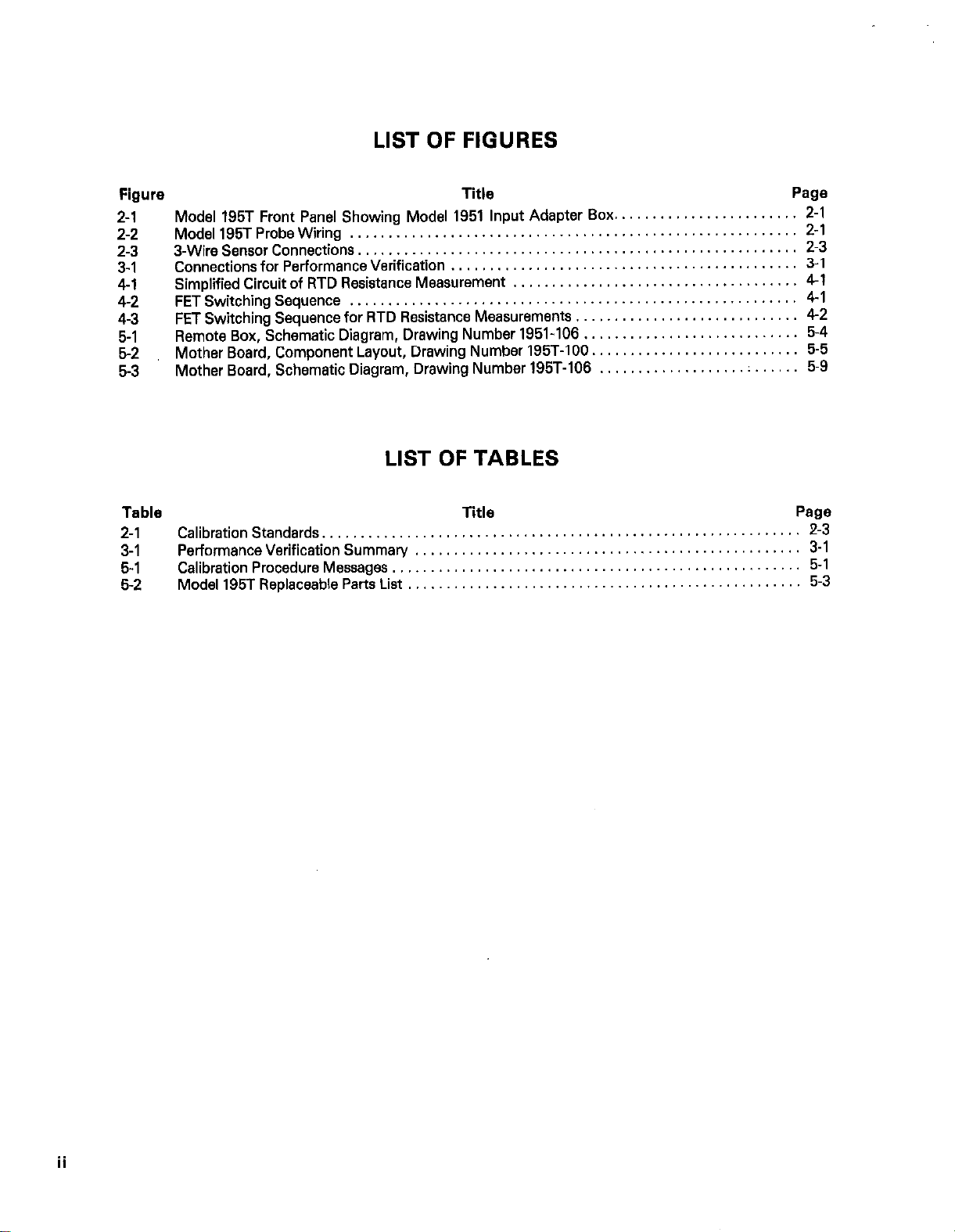
LIST OF FIGURES
Figure
2-l Model 195T Front Panel Showing Model 1951 Input Adapter Box
2-2
2-3
3-1
4-l
4-2
4-3
5-1
5-2
5-3
Model195TProbeWiring
3-Wire Sensor Connections.
Connections for Performance Verification
Simplified Circuit of RTD Resistance Measurement
FETSwitchingSequence
FET Switching Sequence for RTD Resistance Measurements
Remote Box, Schematic Diagram, Drawing Number 1951-106
Mother Board, Component Layout, Drawing Number 195T-100
Mother Board. Schematic Diagram, Drawing Number 195T-106
..........................................................
........................................................ 2-3
..........................................................
Title
.............................................
.....................................
.............................
............................
...........................
................... : ...... 5-9
LIST OF TABLES
Table Title
2-1 Calibration Standards.,
3-1 Performance Verification Summary
5-1
5-2
Calibration Procedure Messages,
Model 195T Replaceable Parts List
............................................................
..................................................
.................................................... 5-1
...................................................
Page
........................ 2-l
2-l
3-1
41
4-1
4-2
5-4
5-5
Page
2-3
3-1
5-3
Page 7
SECTION 1
GENERAL INFORMATION
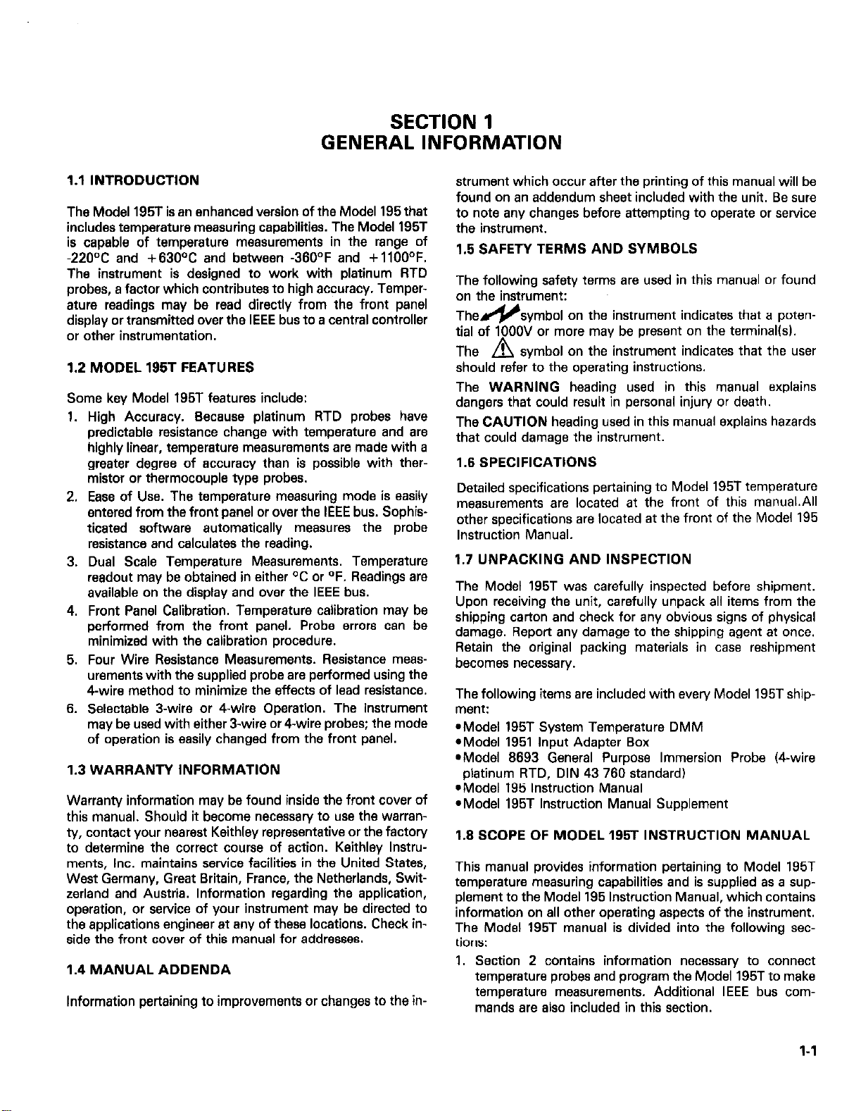
1.1 INTRODUCTION
The Model 195T is an enhanced version of the Model 195 that
includes temperature measuring capabilities. The Model 195T
is capable of temperature measurements in the range of
-220°C and +630°C and between -360°F and +llOO°F.
The instrument is designed to work with platinum RTD
probes, a factor which contributes to high accuracy. Temperature readings may be read directly from the front panel
display or transmitted over the IEEE bus to a central controller
or other instrumentation.
1.2 MODEL 195T FEATURES
Some kev Model 195T features include:
High Accuracy. Because platinum RTD probes have
1.
predictable resistance change with temperature and are
highly linear, temperature measurements are made with a
greater degree of accuracy than is possible with thermistor or thermocouple type probes.
Ease of Use. The temperature measuring mods is easily
2.
entered from the front panel or over the IEEE bus. Sophis-
ticated software automatically measures the probe
resistance and calculates the reading.
3.
Dual Scale Temperature Measurements. Temperature
readout may be obtained in either OC or OF. Readings are
available on the display and over the IEEE bus.
Front Panel Calibration. Temperature calibration may be
4.
performed from the front panel. Probe errors can be
minimized with the calibration procedure.
Four Wire Resistance Measurements. Resistance msas-
5.
urements with the supplied probe are performed using the
4-wire method to minimize the effects of lead resistance.
6.
Selectable 3-wire or 4.wire Operation. The instrument
may be used with either 3-wire or 4-wire probes; the mods
of operation is easily changed from the front panel.
1.3 WARRANTY INFORMATION
Warranty information may be found inside the front cover of
this manual. Should it become necessary to use the warranTV, contact Your nearest Keithley representative or the factory
to determine the correct course of action. Keithlsy Instruments, Inc. maintains service facilities in the United States,
West Germany, Great Britain, France, the Netherlands, Switzerland and Austria. Information regarding the application,
operation, or service of Your instrument may be directed to
the applications engineer at any of these locations. Check inside the front covsr of this manual for addresses.
1.4 MANUAL ADDENDA
Information pertaining to improvements or changes to the in-
strument which occur after the printing of this manual will be
found on an addendum sheet included with the unit. Be sure
to note any changes before attempting to operate or service
the instrument.
1.5 SAFETY TERMS AND SYMBOLS
The following safety terms are used in this manual or found
on the instrument:
The&symbol on the instrument indicates that a poten-
tial of 1OOOV or more may be present on the terminal(s).
The A symbol on the instrument indicates that the user
should refer to the operating instructions.
The WARNING heading used in this manual explains
dangers that could result in personal injury or death.
The CAUTION heading used in this manual explains hazards
that could damage the instrument.
1.6 SPECIFICATIONS
Detailed specifications pertaining to Model 195T temperature
measurements are located at the front of this manual.All
other specifications are located at the front of the Model 195
Instruction Manual.
1.7 UNPACKING AND INSPECTION
The Model 195T was carefully inspected before shipment.
Upon receiving the unit, carefully unpack all items from the
shipping carton and check for any obvious signs of physical
damage. Report any damage to the shipping agent at once.
Retain the original packing materials in case reshipment
becomes necessary.
The following items are included with every Model 195T shipment:
-Model 195T System Temperature DMM
*Model 1951 Input Adapter Box
*Model 8693 General Purpose Immersion Probe (Cwire
platinum RTD, DIN 43 760 standard)
*Model 195 Instruction Manual
*Model 195T Instruction Manual Supplement
1.8 SCOPE OF MODEL 195T INSTRUCTION MANUAL
This manual provides information pertaining to Model 195T
temperature measuring capabilities and is supplied as a supplement to the Model 195 Instruction Manual, which contains
information on all other operating aspects of the instrument.
The Model 195T manual is divided into the following sections:
1. Section 2 contains information necessary to connect
temperature probes and program the Model 195T to make
temperature measurements. Additional IEEE bus commands are also included in this section.
l-l
Page 8
2. Procedures necessary for checking temperature measuring
accuracy are contained in Section 3.
3. Basic theory of operation may be found in Section 4.
4. Servicing information, including calibration, and a list of
replaceable parts is located in Section 5.
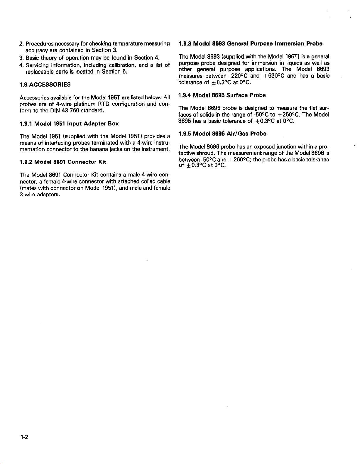
1.9 ACCESSORIES
1.9.3 Modal 8693 General Purpose Immersion Probe
The Model 8693 (supplied with the Model 195Tl is a general
purpose probe designed for immersion in liquids as well as
other general purpose applications. The Model 8693
measures between -22OOC and +630°C and has a basic
.tolerance of f0.3OC at 0%.
Accessories available for the Model 195T are listed below. All
probes are of 4-wire platinum RTD configuration and con-
form to the DIN 43 760 standard.
1.9.1 Model 1951 Input Adapter Box
The Model 1951 (supplied with the Model 195Tj provides a
means of interfacing probes terminated with a 4-wire instrumentation connector to the banana jacks on the instrument.
1.9.2 Model 9691 Connector Kit
The Model 8691 Connector Kit contains a male 4-wire con-
nector, a female 4-wire connector with attached coiled cable
(mates with connector on Model 1951). and male and female
3-wire adapters.
1.9.4 Modal 8695 Surface Probe
The Model 8695 probe is designed to measure the flat surfaces of solids in the range of -5OOC to +260°C. The Model
8695 has a basic tolerance of f0.3Y at 0%.
1.9.5 Modal 8696 Air/Gas Probe
The Model 8696 probe has an exposed junction within a protective shroud. The measurement range of the Model 8696 is
between -50°C and + 260°C; the probe has a basic tolerance
of *0.3°C at OOC.
1-2
Page 9

SECTION 2
OPERATION
2.1 INTRODUCTION
This section contains information necessary to connect the
temperature probe to the Model 195T and program the unit
for temperature measurements. Also included is information
on additional IEEE-488 bus commands and data formats.
2.2 PROBE CONNECTION
The Model 195T is supplied with the Model 1951 Input Adapter Box, designed to interface the unit with a standard 4-wire
instrumentation connector. To connect the temperature
probe to the instrument, proceed as follows:
WARNING
To avoid
nect all test leads from the Model 196T
before connecting the adapter box or tampsrsture probe.
1. Connect the Model 1951 to the VOLTS OHMS and OHMS
SENSE terminals on the front or rear panel of the Model
195T as desired. The input box is designed with suitable
banana plugs designed to connect with the Model 195T
banana jacks and includes a 4-wire connector, as shown in
Figure 2-l. The box is designed to connect only one way.
2. Check to see that the rear panel INPUTS switch is in the
correct position.
3. Connect the temperature probe to the jack on the front of
the adapter. If desired, a probe may be wired using the
connections shown in Figure 2-2.
possible
shock hazards, discon-
NOTE
As shipped, the Model 195T is calibrated to use
platinum probes conforming to the DIN 43 760
standard tapha =0.00385). Instrument calibration may be changed for other standards as
described in Section 5.
2
2
m
m
~SENSOR .SENSOR
Figure 2-2. Model 195T Probe Wiring Figure 2-2. Model 195T Probe Wiring
2.3 TEMPERATURE MEASUREMENT PROCEDURE
Using the instrument to measure temperature is simply a mat-
ter of entering front panel Program 6, es described below.
1. Connect a suitable probe to the instrument as described in
the last paragraph.
(SST SYSTEM TEMPERATURE DMM
Figure 2-l. Model 196T Front Penal Showing Model 1961 input Adapter Box
2-1
Page 10

2. Turn on the power to the instrument and allow it to warm
up for at least one hour to achieve rated accuracy. Upon
power-up, the instrument will display the programmed line
freauencv and software revision level similar to the example ‘below.
l=l5llt
S
The Model 195Tzp message differs from the Model
195 message in that the “t” in the software revision level
indicates the instrument is configured for temperature
measurements.
3. Press PRGM. The instrument will prompt for a program
number as follows:
turs mode. See Section 3 of the Model 195 Instruction
Manual for front panel program details.
3. The instrument may be placed in the one-shot mode when
making temperature measurements by using Program 9.
See Section 3 of the Model 195 Instruction Manual for
details.
4. As with other Model 195T msasurements, the final, filtered
temperature reading is not displayed until the FILTER light
ceases flashing.
5. Program 0 doss not cancel the temperature mode.
2.4 IEEE BUS CONTROL OF TEMPERATURE MEASUREMENTS
pFF7
4. Press 6. The instrument will briefly display the program
number as follows:
-1
5. Following the program number, the unit will enter the
temperature measuring mods; each time the PRGM, 6 key
stroke sequence is performed, the instrument will toggle
between the OC and “F temperature modes. The flashing
decimal point shows the conversion rate.
6. In the “C mode, a typical reading might be:
jl
For a typical reading in the OF mods, the display might appsarasfollows~ D 7~icIcI F I
7. If the temperature is outside the measuring range of the instrument, or if the probe is open, the following message
will be disolaved:
8. Place the probe on or in the material to be measured and
take the temperature reading. Allow sufficient time for the
reading to stabilize.
WARNING
Do not
potential more than 30V RMS, 42.4V peak
above earth ground, or a shock hazard may
result.
subject
the temperature probe to a
9. To cancel the temperature mode, press a valid FUNCTION
button, such as VOLTS,
NOTES:
1. The instrument may be operated in either the 4% digit or
5’/i digit resolution mode while in the temperature mods.
The RESOLN button on the front panel controls display
resolution. When in the 5’h digit mods, the o character is
replaced by the least significant digit of the temperature
reading.
2. Temperature measurements may be stored in the internal
buffer by entering Program 7 after entering the tempera-
The instrument may be placed in the temperature measuring
mods with commands given over the IEEE bus, and temperature data may be read over the bus as described in the following paragraphs.
2.4.1 IEEE Temperature Commands
The following commands control the Model 195T over the
IEEE bus:
F5 Places the instrument in the OF mode.
F6 Places the instrument in the OC mode.
Sl Default rats mods from front panel hates must be pro-
grammed with appropriate rats commands).
NOTES:
1. A DCL or SDC command transmitted over the bus to the
instrument will cancel the temperature mode.
2. As with other device-dependent commands, the instrument must be in the remote mode before it will respond to
temperature commands. See Section 4 of the Model 195
Instruction Manual for complete details on using the unit
over the IEEE-488 bus.
Programming Example-To
program the instrument for
temperature measursmsnts in “C, enter the following
statements into the HP-85:
REMOTE 716 (END LINE)
OUTPUT 716; “F8X” (END LINE1
When the END LINE is pressed the second time, the instrument will enter the OC temperature mode.
2.4.2 IEEE Bus Temperature Data Format
Temperature data sent over the IEEE bus has a format similar
to other instrument data. Formats for the two temperature
modes are:
DEGFnnnn.nnE+n “F Mods
DEGCnnnn.nnE+ n OC Mode
NOTES
1. The data prefix is not present in the Gl, G3 or G5 data
modes.
2. The bus reading rate may be increased by sending the
following command string: SlPOX. However, noisier
readings will result.
2-2
Page 11

3. Turning the multiplex mode off with the Al command will
also increase the reading rate, but probe heating may increase, possibly affecting accuracy.
Programming Example-Connect a suitable probe to the
instrument and enter the following statements into the HP-85
keyboard:
REMOTE 716 (END LINE1
OUTPUT 716; “F5X” (END LINE)
ENTER 716; A$ (END LINE)
DISP AS (END LINE)
After the last statement is executed, the temperature data
string will be displayed on the CRT.
different calibration parameters, as summarized in Table 2-l.
Note that it is imperative that the instrument be calibrated for
the standard for which the probe is designed, or inaccurate
temperature readings will result. Instrument calibration is
covered in detail in paragraph 5.2.
2.5 3-WIRE
SENSOR OPERATION
As supplied, the Model 195T is designed for operation with
4-wire probes, such as the supplied Modal 6693 probe.
However, the unit may be used with an appropriate 3.wire
platinum RTD probe by using the connections shown in
Figure 2-3. Before using a 3-wire probe, the instrument must
be properly programmed as described in the calibration pro-
cedure in Section 5 of this manual.
WARNING
To avoid possible shock hazards, discon-
nect all test leads from the Model 196T
before connecting the temperature probe.
NOTE
Model 195T temperature accuracy figures given
in the specifications are based on 4-wire operation.
2.6 CALIBRATION STANDARDS
As shipped, the Model 195T is calibrated for use with probes
conforming to the DIN 43 760 standard. Another popular
temperature standard is the IPTS-66 standard, which uses
Figure 2-3. 3-Wire Sensor Connections
Table 2-1. Calibration Standards
DIN 43 760 IPTS-68
Parameter Standard Standard
R, (Probe resis- 100.000
100.003
tance at O°C)
Alpha 0.00385
Delta 1.502
A4, C4
l l
0.00392
1.49633
*Not directly programmable; automatically programmed by
selection of DIN 43 760 or IPTS-66 standard during calibration.
2-312-4
Page 12

Page 13

SECTION 3
PERFORMANCE VERIFICATION
3.1 INTRODUCTION
This section contains information necessary to verify that
Model 195T temperature measurements are made within
specified accuracy. Model 195T temperature specifications
are located at the front of this manual. Performance verification may be performed when the instrument is first received
to ensure that no damage or change in calibration has occur-
red during shipment. The verification procedure may also be
performed following calibration. If performance is substandard, use the calibration procedure in Section 5 to bring the
unit back within specifications. If that procedure does not
bring the unit within specifications, complete calibration may
be required; see Section 7 of the Model 195 Instruction
Manual.
NOTE
If the instrument does not meet specifications,
and it is still under warranty, (less than 12
months since the date of shipment) contact your
Keithley representative or the factory to deter-
mine the correct coursa of action.
3.2 ENVIRONMENTAL CONDITIONS
Verification measurements should be made with the instru-
ment at an ambient temperature between 18O and 28OC (65e
to 82°F) at a relative humidity of less than 80%.
3.3 RECOMMENDED EQUIPMENT
The following equipment is recommended for performing the
verification procedure:
Gen Rad precision decade resistance box Model 1433T. or
equivalent 1 fO.Ol% tolerance). Other equipment may be
used as long as the above accuracy figure is met or exceeded.
and seeing that the displayed reading falls within the required
range.
NOTE
The following procedure assumes the instrument is calibrated for the DIN 43 780 standard
Iapha =0.00385). Other standards will require
different resistor values. See Section 5 for information on calibration.
WARNING
To avoid possible shock hazards, discon-
nect all other test leads from the unit before
connecting the decade box.
I. Connect the precision decade resistance box to the Model
195T as shown in Figure 3-l. Four wire connections must
be used as shown on the diagram. Make sure the INPUTS
switch is in the front panel position and that the instrument is programmed for 4-wire operation (paragraph
5.2.4).
2. Enter the OC temperature mode by pressing the PRGM
and 6 buttons in sequence. If the display shows unit is in
the “F mode, press PRGM and 6 in sequence again. Make
sure the display is in the 5% digit resolution mode; also
see that
ZERO
is disabled.
3. Refer to Table 3-1, which summarizes the verification
resistance values. To check Model 195T accuracy at each
of the points, set the decade box to the indicated resistance value and see that the displayed Model 195T
reading falls within the required range.
3.4 INITIAL CONDITIONS
Before performing the verification procedure, make sure the
Model 195T meets the following conditions:
1. If the instrument has been subjected to temperatures
below 18°C (65°F) or above 28OC (82”F), allow sufficient
time for it to reach a temperature within this range. Typically, it takes one hour to stabilize an instrument 10°C
118°F) outside the normal range.
2. Turn on the power to the Model 195T and allow it to warm
up for at least one hour before beginning the verification
procedure.
3.5 VERIFICATION PROCEDURE
Model 195T temperature verification is based on substituting
precise, known resistance values for the temperature probe
Figure 3-l. Connections for Performance Verification
Table 3-1. Performance Verification Summary
Allowable Reading
(18O to 2E°Cl
-200.12 to - 199.8OT
-100.13 to - 99.87OC
0.10 to + O.lOT
+ 99.87 to + 100.13”C
+199.84 to +200.16°C
+399.48 to +400.58°C
+599.42 to +600.58T
3-l 13-2
Page 14

Page 15

SECTION 4
THEORY OF OPERATION
4.1 INTRODUCTION
Model 195T temperature readings are based on the 4-wire
resistance measurements of a platinum RTD (resistance
temperature detector). As the probe temperature rises, its
resistance increases as well, although not in a precisely linear
manner.
In the Model 195T, these resistance measurements are made
in the normal manner, but, during the measurement process,
thermal voltages generated by dissimilar electrical contacts
are cancelled cut. This cancellation is achieved by making
two measurements: the first is the voltage across the OHMS
SENSE HI and LO terminals with current flowing through the
RTD probe; the second measurement is made with no our-
rent flowing through the probe. These voltage measurements
are then used bv the microcomputer to calculate the temperature. Because the RTD current has a 25% duty cycle, probe
heating is reduced; also, the off cycle allows thermal voltages
to be measured.
4.2 RTD RESISTANCE MEASUREMENT
Figure 4-l shows a simplified schematic of the Model 195T
and RTD probe during temperature measurements. V,
through V, represent thermal contact voltages generated by
dissimilar metals. VRTp is the voltage developed across the
probe when current I IS flowing. The remaining circuitry to
the right is the normal Model 195 input and multiplexer cir-
cuitly.
v,,-v,, = v, t v, t v,
Since the voltage is measured at the OHMS SENSE terminals, V, and V, are insignificant.
The resistance value of the probe can then be calculated as
follows:
RRTO = Rr,V,T,‘(Vr~fHt-Vr,fLO)
4.3 FET SWITCHING SEQUENCE
As with all other Model 195T measurements, RTD resistance
measurements are performed by switching various input
FETs on and off. Figure 4-2 shows the general switching
sequence for RTD measurements. Figure 4-3 shows the flow
char-i for the switching sequence. Each FET is assumed to be
on when a positive pulse occurs.
Flgura 4-2. FET Switching Sequence
During the first phase of the measurement cycle, 0121 is
turned on, causing current to flow through the RTD. Qlll,
QIIO, Ql09 and Q108 are then turned on in sequence to
measure the voltage across the RTD with current flowing
through it. During the second phase, Ql21 is turned off, and
Qlll and 0110 are turned on in sequence to perform the
necessary measurements for the last phase. This last phase is
repeated three times to provide the necessary duty cycle.
4.4 READING CALCULATIONS
Figure
When current is flowing through the RTD probe, the voltage,
as seen at the OHMS SENSE HI and LO terminals, is:
With no current flowing, the voltage between these two terminals is:
4-I. Simplified Circuit of RTD Resistance Meas-
urements
VH,-VLO = v, + VRTD + v, + v,
Once the measurements are stored within. the microcomputer, it is a simple matter to calculate the final reading.
Above O°C, these calculations era performed using the
following relationships:
-A+JAz-4B[l-RJR01
T,=
Where:
A=fl+d/lOO)
B = -cSflO-41
01 and 6 are given constants
Ro is the probe resistance at 0°C
Rt is the probe resistance at the measured temperature
T, = 9/5T, t 32
28
4-1
Page 16

Example:
Assume the Model 195T is used with a probe conforming to
the DIN 43 760 standard and is measuring a temperature of
2.10°C. At this temperature with this probe, the values are:
R. = 100.000
R,=179.510
OL = 0.00385
S=l.502
A=0.00385[1+ (I .502/100)1=0.0039078
B=-(10-4)10.00385)(1.502)=-5.7827x lO-7
0.0039079+J(0.0039078l*-4~ -5.7827X lO~')[l-(I-79.51/100)1
T,-
Zl-5.7927x10⁻⁷)
T,=210°C
Below OOC, two additional constants, A4 and C4, are used in
a fourth order polynomial to calculate the temperature
reading. These constants are not directly programmable, but
their values will change in accordance with the selected standard (DIN 43 760 or IPTS-68). which can be programmed
during the calibration procedure as described in paragraph
5.2.4.
Figure 43. FET Switching Sequence for RTD Resis-
tance Measurements
42
Page 17

SECTION 5
SERVICING INFORMATION
5.1 INTRODUCTION
This section contains temperature calibration procedures.
Also included is a list of replaceable parts for the Model 195T.
5.2 CALIBRATION
Temperature calibration is performed by using front panel
Program 5. The basic procedure is similar to that used for
calibrating other instrument functions. The following paragraphs describe the basic calibration procedure.
NOTE
Proper temperature calibration requires that all
other functions be properly calibrated fespecial-
ly the 2000 and 2kD ranges). See paragraph 7.5
of the Model 195 Instruction Manual for those
calibration procedures.
5.2.1 Environmental Conditions
Calibration should be performed under laboratory conditions
having an ambient temperature of 23 f 1°C and e relative
humidity of less than 80%. If the instrument has been sub-
jected to temperatures outside this range, or to higher
humidity, allow at least one additional hour for operating con-
ditions to stabilize.
5.2.2 Warm-Up Period
Before beginning the calibration procedure, turn on the
power to the Model 195T and allow the unit to warm up for at
least one hour.
5.2.3 Calibration Constants
During the calibration procedure, the instrument will prompt
for a number of constants. Table 5-I summarizes prompt
messages. Along with each prompting message, the display
will show either the factory default value or the previously
programmed value for each constant. The inputs required for
calibration include:
1. Alpha-Used for reading calculations above O°C (for DIN
43 760 standard, alpha =0.00385; for IPTS-68 standard,
alpha=0.003921.
2. Delta-Also used for reading calculations above O°C (for
DIN 43 760, delta = 1.502; for IPTS-68, delta = 1.496331.
3. t=OV-the probe resistance at O°C.
4. DIN or NBS (IPTS-68) standard-Used to select appro-
priate A4 and C4 constants for better conformity below
OT.
5. 3- or 4-terminal operating mode selection.
5.2.4 Front Panel Calibration Procedure
The Model 195T is factory calibrated to conform to the DIN
43 760 standard. The following calibration procedure may be
used to change instrument calibration to another standard, or
to optimize instrument performance for use with a specific
probe. Proceed as follows:
NOTE
Program 0 may be used at any time during the
calibration procedure to return the instrument to
the normal mode. Simply press PRGM and 0 in
seauence.
Remarks
$*] Fzz;:,“for alpha constant.
I
r-2m-rj
ln standard.
m ;roro&~r 3- or4-wire Probe ~,~~~~~mpt,
I progress.
Prompts for delta constant. Default delta value displayed after
Prompts for probe resistance at Default probe resistance value
Prompts for DIN or NBS IPTS-68
Shows temperature calibration in
Default alpha value displayed after
prompt (DIN 43 760=0.00385
IPTS-68=0.003921
prompt. (DIN 43 760= 1.502
IPTS-68 = 1.49633)
displayed after prompt.
Programmed standard displayed with
Programmed operating mode displayer
5-1
Page 18

I. Press PRGM. The instrument will prompt for a program
number as follows:
I
,
2. Press 6. The instrument will briefly display the
number:
rFzTProj
.._ -
/
1
3. Following the program number, the unit will enter the
temperature mode. To continue with calibration, press
PRGM. The Model 195T will again prompt for a program
number:
4. Press 5. The instrument will then display the program
number followed bv a prompt for the alpha parameter as
follows:
ILLPH
5. Following the prompt, the default alpha value (for the
DIN 43 760 standard) will be displayed:
6. If the displayed value of alpha is to be used, press ENT. if
a new value of alpha is to be used, key in the digits and
press ENT (the allowable range of alpha is
0.00360~alpha~0.00420). For example, for the
IPTS-68 standard, key in a value of 0.00392.
7. The unit will now prompt for the delta constant with the
followina messaae:
8. After the oromot. the default value (for the DIN 43 760
standard) ‘will be displayed:
9. To use the displayed value, simply press ENT. To change
the value, key in the digits and press ENT (the allowable
range for delta is 1.4cdelta ‘1.61. For example, for the
IPTS-68 standard, a value of 1.49633 would be used.
10. The instrument will now display a message prompting for
the nominal probe resistance value et 0% as follows:
pJjoc_l
11. Following the prompt, the default probe resistance at O°C
lfor the DIN 43 760 standard) will be displayed:
13. The unit will now prompt for operation on either the DIN
or,NBS (IPTS-68) standard. The importance of thisselection lies in proper conformity for temperatures below 0%
With the NBS standard, the display will appear as
follows:
14. For the DIN standard, the display will show:
15. To select the DIN standard, press the 1 button. To select
the NBS standard: Dress the 2 button. Once the desired
standard is displaieb, press ENT.
16. The instrument will now prompt for selection of 3-wire or
4-wire operation. For 4wire operation, the display will appear as follows:
130r rt~~~~~ 4 ,
L.x-~r
17. Press 3 or 4 to select the desired mod:, then press ENT.
The unit will then display the following message to in-
dicate that calibration is being performed.
(1
After a few seconds, the unit will return to the normal
temperature measurement mode.
NOTE
The following steps must be performed to permanently store temperature calibration constants in NVRAM.
18. Press PRGM. The instrument will prompt for a program
number as follows:
/I
19. Press I. The instrument will briefly display the program
number and then ask if NVRAM storage is desired:
r!FGTF
20. Press ENT. If NV storage is successful, the instrument will
return to normal operation after storing the temperature
calibration values. Momentarily power down the unit
before using the new calibration values.
NOTE
If the calibration jumper has been removed, NV
storage will not be performed. Under these conditions, the following message will be displayed:
12. To use the present value, press ENT. To change the
value, key in the digits and press ENT. Instrument perfor-
mance is guaranteed for values between 850 and 1203,
but the user may experiment with a wider range of values.
NOTE
If the precise probe resistance at 0°C is known,
key in that value instead of the nominal value for
better overall accuracy.
5-2
L no5tr_i
See Section 7 of the Model 195 Instruction Manual for
calibration jumper details.
5.2.5 Temperature Calibration Over the IEEE-488 Bus
The Model 195T temperature calibration sequence may be
performed by sending commands over the IEEE bus with one
of two methods.
Page 19

I. Emulate the front panel control sequence with the H (hit
button) command. (HIOX, H5X. HOX, etc.)
2. Use the V command along with the calibration parameters
after the instrument is in the temperature mode. For example, the following command string might be used:
VO.OO385X VI .49436X VlOO.OOX VIX V4X
Note that it is not necessary to enter Program 5 before
calibrating the instrument with the V command. See Section 4 of the Model 195 Instruction Manual for complete
details on IEEE-488 bus programming.
Programming Example: Enter the following program into
the HP-85 keyboard; be sure to press the END LINE key after
each statement.
Program
10 REMOTE 716
Comments
Set up 195T for remote
operation.
20 CLEAR 716
Return 195T to default
conditions.
30 OUTPUT 716;“F6X”
Program for OC tempera-
turcmode.
40 OUTPUT 716;“VO.OO392X” Program alpha value.
50 OUTPUT 716;“V1.49633X” Program delta value.
60 OUTPUT 716:“V101.00X” Program probe resistance
at 0%.
70 OUTPUT 716;“V2X” Program for NBS stan-
dard.
80 OUTPUT 716;“V3X” Program for 3-wire opera-
tion.
90 END
5.3.2
Parts List
Table 5-2 lists only those parts used by the Model 195T which
are not used in the Model 195. For other Model 195 and
Model 195T parts, refer to Section 8 of the Model 195 Instruction Manual.
Table 5-2. Model 19BT Replaceable Parts List
Keithley
Description
PROM (U112)
Front Panel Overlay
RTD Probe
Box, Adapter
Cover, Adapter Box
Overlay, Adapter Box
Connector, 4 Pin (Male)
Banana Plug
Terminal
Standoff
*Order sami
5.4 TROUBLESHOOTING INFORMATION
sl
ast two digits as present sof
Part Number
195T-800.XX*
195T-301
8693-300
1951-301
1951-302
1951-303
CS-458
EG-15-1
TE-55
ST-137-7
fare revision levf
The Model 195T differs from the Model 195 only in ROM con-
figuration. In the Model 195, software is contained in two
ROMs (one 8k and one 4kl, Ulll and U112. In the Model
195T, these two ROMs are replaced by a single 16k ROM
(U1121. Since this is the only difference between the two instruments, troubleshooting information located in the Model
195 Instruction Manual is also applicable to the Model 195T.
After entering the program, press the HP-85 RUN key. As
each parameter is sent to the Model 195T. the value will appear on the display. Once all parameters have been programmed, the instrument will display the usual “CAL” message
and then return to the normal temperature mode.
5.3 REPLACEABLE PARTS
The following paragraphs contain parts ordering information
and a list of replaceable parts for the Model 195T.
5.3.1 Ordering Information
Keithley Instruments, Inc. maintains a complete inventory of
all normal replacement parts. To place an order, or to obtain
information concerning replacement parts, contact your
Keithley representative or the factory. When ordering parts,
be sure to include the following information:
I. Instrument Model Number
2. Instrument Serial Number
3. Part Description
4. Circuit designation, including schematic and component
layout numbers, if applicable.
5. Keithley Part Number
5.5 COMPONENT LAYOUTS AND SCHEMATICS
Component layouts and schematics for the Model 195T are
located at the end of this section. Only those items associated
with the Model 195T which differ from the Model 195 are
contained in this supplement. For all other component layouts and schematics, refer to the Model 195 Instruction
Manual.
5-3
Page 20

II
1
PRTD
(PROBE1
L,oo~ - - - 7 (SEE SCHEMATIC 195106
1951
14 PINI
I I
PI002 1 JIOl9
>
Jl”‘e VOLTS OHMS HI
I
I
I
JK20 OHMS SENSE LO
I
195T
PAGE 3 OF4 ,ZONE A4+5)
OHMS SENSE HI
2
4-
3
4
A
d
I
B
Figure 5-l. Remote Box, Schematic Diagram, Drawing Number 1951.106
I
C
4
D
I
E I
F
Page 21

I,
5
Y II/ --
Page 22

-
-
-
z
-
-
E
Figure 52. Mother Board, Component Layout, Drawing
Number 19!X-100 (Sheet 2 of 21
Page 23

.l
1
2
3
JF
e
4
5
“,Y C”*I*I”N
IEEE-
-6
Figure 5-3. Mother Board, Schematic Diagram, Draw-
ing Number 195T-106
59/510
Page 24

Page 25

Keithley Inetrumente, Inc./28775 Aurora Road/Cleveland, Ohio 44139/U.S.A./(218) 24&0400/Telex: SE5469
WEST QERMANY: Keithlsy Instruments QmbHlHeiglhofstrasse 5/D-6COO Monchen 70/106917144065/Telex: 521 21 60
GREAT BRITAIN: Keithley Instruments, Ltd./l, Boulton Road/Reading, Berkshire RGZ ONL/107341 66 12 67/T&x: 647047
FRANCE: Kelthley Intirumants SARLlZ Eis, Rue Ldon Bluml6.P. 60/91121 Palaiiu Cedex/(GI 011.51.55/Telex: 600933F
NETHERLANDS: Keithley Instruments SVlArkelsedijk 4/NL-4206 AC Goriyhem/(01830) 25577/Telex: 24 664
SWITZERLAND: Keithlsy In&umsntr SAIKriesbachstr. 4/CH8600 Dubendo!f/Ol 621 94 M/Telex: 57 536
AUSTRIA: Keithley lnst~msnm Gss.m.b.H./DOMingw Hauptstr. 32/A-1190 Wien10222 314 269/Telex: 13 45 Mf
 Loading...