

Page 1
IEEE-488 Programming Guide
Model 194A
High Speed Voltmeter
Ql.987, Keithley Instruments, Inc.
Instrument Division
Cleveland, Ohio, U.S.A.
Document Number: l94A-903-01 Rev. A
Page 2
TABLE OF CONTENTS
......
....
..
1
7
37
41
47
About This Programming Guide .............................................................. .,
Computer Programming Syntax ................................. .: .. ., ............ ; .............. 3
Single Channel Programming ...................................
Dual Channel Programming ................. -~__ __ ................................................ 11
Single and Continuous Trigger Arming .............................................. ., .......... 17
SRQ~andErrorHandling.. ................... ;...:~ ........... .: .... .._..... .... ..I ...... .._ ....... 21
Binary DataTransfer .......................................................................... 29
Reading Buffer Operation ...................................
Using Translator ...................................................
Using External Sample Triggering ................................
Generating Bus Time Information ............................................... _ ............... 55
Appendix A - Device-Dependent Commands~ ...................... .~~.;. :, .I. : ........... ., ......... ~A-1
Appendix B - Data Formats ................................................................... B-l
...............................
I
_.
.,
..
.............................
._._.
................
_
.......................
._.~.
., _ .,
Appendix C - Status Words and SRQ Format I .................................. .I .............. C-l
Appendix D - Front Panel Modes and Equivalents IEEE-488 Commands ........................... D-l
Appendix E - Data~ Transmission and NRFD Hold-off Times ...... ; .............................. E-l
Page 3
ABOUT THIS PROGRAMMING GUIDE
This programming guide is intended as a tt.&xial on a number of programming conceptss
associated with the Model 194A. It is not intended to replace the IEEE-488 programming
section of the Instruction Manual, which should be consulted for detailed programming
information.
Programming concepts discussed in this guide include:
l Programming a single-channel unit and obtaining data.
l Programming a dual-channel unit and requesting data.
l Single/continuous arming and~triggering.
l Using binary data transfer to optimize speed.
l Using SRQ and error word to minimize controller overhead.
l Buffer operation, including use of buffer pointers.
l Using Translator to increase readability and emulate-other instrumentation.
In addition to these fundamental concepts, applications programs for external sample tiggering, plotting data, and trigger performance and timing are also included. Fmally, reference
information such as device-dependent commands, data formats, and error words is also
supplied.
l/2
Page 4
COMPUTER PROGRAMMING
SYNTAX
All the example programs in this guide are written in Hewlett=Packard BASIC 4.0, which
is used on the Series 200 and 300 computers. This programming language was chosen for
these examples because of its ease of understanding, as well as its powerful subset of commands and statements controlling the IEEE-488 bus.
Most BASIC 4.0 statements are very similar to those used~.in other BASIC languages; however,
there are some statements associated with IEEE-488 bus Ii0 that require discussion. The
following provides a brief overview of some of the statements you will encounter in the various
programs in this guide. Refer to the BASIC 4.0 Reference for more detailed information.
OUTPUT
OUTPUT allows you to send a variable or string over the bus, and it may take on one c$
several forms. A typical syntax is:
In this instance, 7 specifies the interface select code, while 09 is the primary address of the
instrument. FlX is a literal string that will be transmitted to the instruments when the statement~ is executed.
ENTER
ENTER performs the opposite-function,~ allowing the transmission of data from the instru-
ment to the computer. Typical syntax for this statement is;
Again, 7 specifies the interface select code, while 09 represents the primary address of the
instrument. .A$ is a string variable into which incoming data is placed. Keep in mind that
A$ must be dimensioned large enough to hold all Rpected characters. As an alternative,
the ENTER statement-can directly input the data into a numeric variable, assuming that the
proper instrument data format is used.
SPOLL
SPOLL serial polls the instrumentand places its status byte in a numeric variable as follows:
Here again, 709 represents the interface select code and primary address of the instrument.
S is a numeric variable which will contain the decimal value of the status byte after the state-
3
Page 5

ment is executed. The status byte-can then be checked by ANDing or BIXng S to determine
the status of the required bits. These bits can yield certain information such as reading,overflow
and ready for a new command.
BIT
BIT can be used to detetie the bit status of numeric variables:
In this example, the status of bit 5 of the variable S is placed into A.
TRIGGER
TRIGGER sends a GET (Group Execute Trigger) to a device as follows:
A GET is one of many methods that can be used~& initiate a~ Model 194A +?v+urement~
In order to~~use~~ this form of triggering, the GET t$ger mode must be programmed, and
the A/D converter must be armed. Note that programming a trigger mode over the bus
automatically arms the A/D converter.
ASSIGN
ASSIGN is used to assign an I/O path, as in the following example:
Following ASSIGN execution, the attribute D194 will be associated with the interface code
and primary address. Another form of ASSIGN is used to-define the IiO~buffer:
ASSIGM IZufTU BUFFER k8 ‘~
TRANSFER TRANSFER
TRANSFER is used to perform a rapld I/O data transfer sequence. Usualli, TRANSFER is TRANSFER is used to perform a rapld I/O data transfer sequence. Usualli, TRANSFER is
used with the binary dump feature oft the Model 194A for most~rapid data transfer. Using used with the binary dump feature oft the Model 194A for most~rapid data transfer. Using
this combination, data can be transferred at a rate as high as 90K bytes per second. this combination, data can be transferred at a rate as high as 90K bytes per second.
Typical syntax for TRANSFER is:
TRAHSFER I?11194 TO WUF; COU~KT-i00B,W~Il
In this instance, a total of 1000 bytes will be tr~mitted from the Model 194A to~~the~internal
buffer.
4
Page 6
STATUS
SX4TUS allows access to certain computer status registers. Most often, this statement is used
to either determine if aii SRQ has occurred, or dear an SRQ interrupt. Typical syntax is:
Here, 7 is the interface select code, and the second 7 is the status register being accessed.
The value of the status register is placed in the variable S when the statement is executed.
ON INTR and ENABLE INTR
These two statements work together to enable interrupts and to tell the computer where to
go for next line execution. A typical ON INTR statement is:
In this case, when the computer detects an IEEE-488 interrupt, it-begins executing the
subroutine at line 4000.
SRQ is the most often used type of interrupt for the IEEE-488 bus. Using BASIC 4.0, SRQ
interrupts are enabled as follows:
Once enabled, an SRQ Wi cause the computer to branch to the line number specified by
the ON INTR statement. Typically, an error handling subroutine will be incorporated at that
point to determine the reason for the SRQ and to handle any other required tasks.
5/6
Page 7
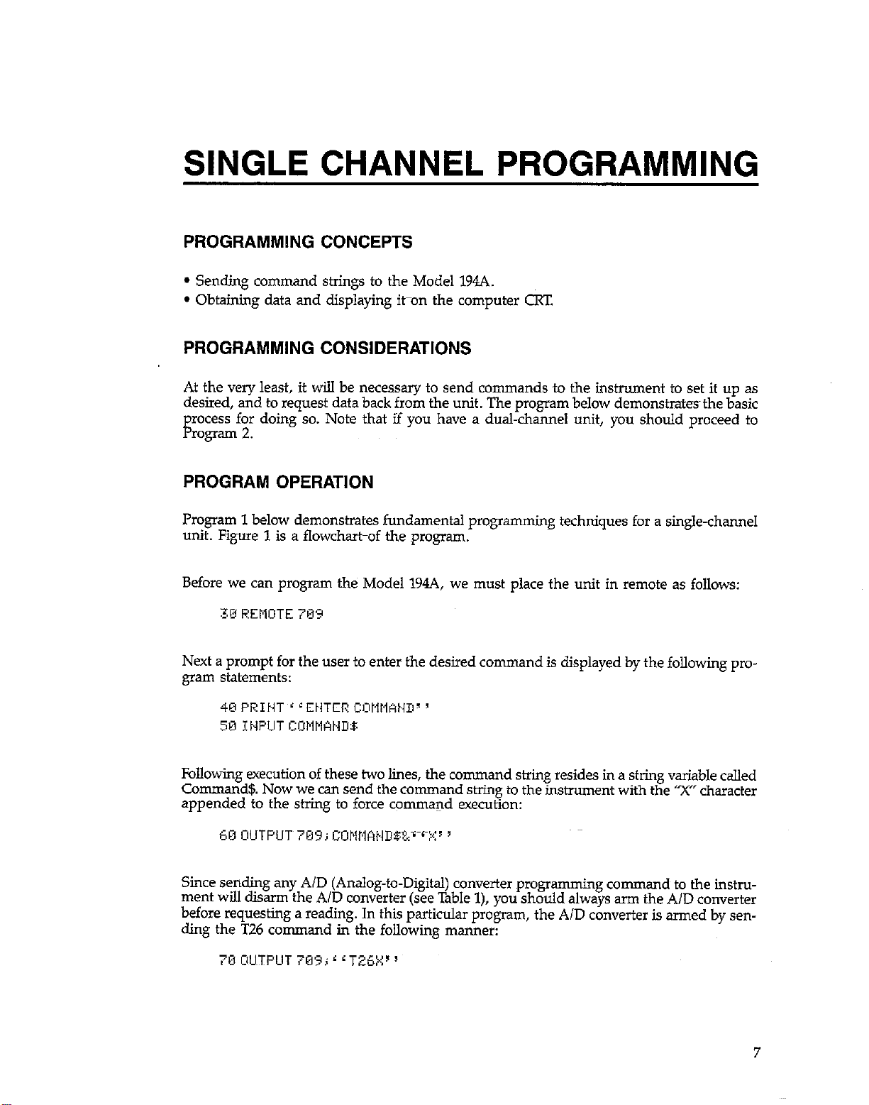
SINGLE CHANNEL PROGRAMMING
PROGRAMMING CONCEPTS
l Sending command strings to the Model 194A.
l Obtaining data and displaying iton the computer CRT
PROGRAMMING CONSIDERATIONS
At the very least, it will be necessary to send commands to the instrument to set it up as
desired, and to request data back from the unit. The program below demonstrates~ the basic
recess for doing so. Note that if you have a dual-channel unit, you should proceed to
F
rogTam 2.
PROGRAM OPERATION
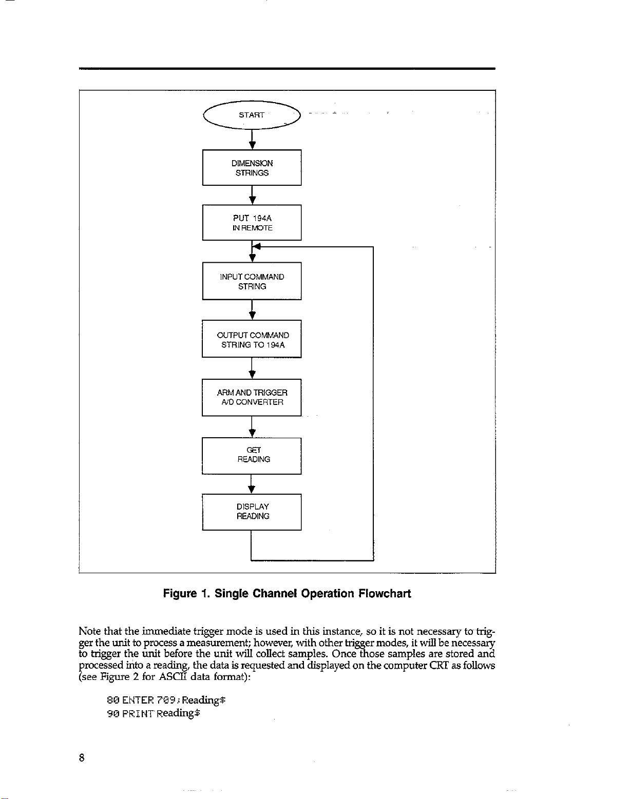
Program 1 below demonstrates fundamental programming
unit. Figure 1 is a flowchartof the program.
Before we can program the Model 194A, we must place the unit in remote as follows:
Next a prompt for the user to enter the desired command is displayed by the following program statements:
Following execution of these two lines, the command suing resides in a string variable called
Command!& Now we can send the command string to the instrument with the ‘X” character
appended to the string to force command execution:
Since sending any AID (Analog-to-Digital) converter programming command to the instrument will disarm the AID converter (see Table 1), you should always arm the AID converter
before requesting a reading. In this particular program, the AID converter is armed by sen-
ding the T26 command in the following manner:
techniques for a single-channel
7
Page 8
PUT ,944
I
IN REM3T.E
INPUT COMMAND
STRING
c
OUTPUT COMMAND
STRING TO 194.4
c
ARM AND TRIGGER
/vD CONVERTER
I
r
c
I
Figure 1. Single Channel Operation Flowchart
Note that the immediate trigger mode is used in this instance, so it is not necessary to~~trigger the unit to process a measurement; however, with other tri
to trigger the unit before the unit will collect samples. Once t
processed into a reading, the data is requested and displayed on the computer CRT as follows
(see Figure 2 for ASCII data format):
80 ENTER 70’3; Readings
YM PEItKReading8
er modes, it will be necessary
ose samples are stored and
PB
Page 9
PREFIX
(GO G-2, G3. GS)
BUFFER
SUFFIX (G2, GS) WITH CF
EOIASSERTED~
N=NORMAL A
0 = OVERFLOW
Z=ZEROED
READING
I = INVALID
MEASUREMENT
RMS = TRMS
A”G = AVERAGE
+PK = +PEAK
-PK = -PEAK
DIF = CHI CH2
RAT = CH1ICH2
DEV I STANDARD DE”,AT,ON
P.P = PEAK TO PEAK
INT= INlEGRAL
DC” = WAVEFORM
RCL = RECALL
+-I
N DCV * 1.2345 E + 0. CH2, 80050 TERMlNATOR
kdST TM,, &&;ToRicRLF
EXFCNENl
~ ~~~
NOTE: SUFFER LCCATDN SHOWS
A I
NUMBER
SAMPLE nnnni, IN WAVE
FORM MODE
Figure 2. ASCII Data Format
Table 1. Commands That Disarm the A/D Converter
Command
Description
I
Recall setup
Function
$P~z?
Number of samples
Filter
Range
Rate
Trigger
w
Z
Delay
7mv-l
RUNNING THE PROGRAM
1. Enter the program into the computer.
2. Run the program by pressing the RUN key. The computer wti promptyou to type in your
command:
9
Page 10
3. Type in the desired command string and then press ENTER. Note that is not necessary
to add the “X” character as it is automatically added by the program. For example, to program the average function and select autoranging, type in FlRO and press ENTER.
4; Once the measurement is completed and the reading is processed, the data string will
appear on the computer display. A typical example is:
ACQUIRING A WAVEFORM USING ASCII DATA TRANSFER
The Model 194A can be used to capture a waveform and then send the data as a series of
readings representing the individual samples. Each individual data string will represents the
voltage of that-particular sample.
To use the Model 194A in this manner, program the instrument for the waveform (FO) function, and then repeatedly request readmgs until all samples have been transferred. For example, to collect 100 samples and read them into a computer, modify Program 1 as follows:
75 FUR I = 1 TU i0EI
35 HEYT I c ,
! Loop 100 times.
! Loop back for next sample.
When the computer prompts~you for a command, type in ‘~ONO,lOO” (include the quotes
because of the comma) and then press ENTER. You should see 100 successive readings appear on the display. Each reading is the numeric value of that particular sample. These samples
can also be placed into a BASIC array for further processing, if required.
For a larger number of samples, or for higher speed data transfer, refer to the section in this
guide on binary data transfer.
Program 1. Single Channel Operation
10
20
30
40
50
60
70
80
90
100
$10
10
Page 11
DUAL-CHANNEL PROGRAMMING
PROGRAMMING CONCEPTS
l Basic command programming of a dual-channel Model 194A.
l Obtaining data fmn a dual-channel Model 194A.
l Demonstrating that both channels share a single IEEE-488 output.
l How to turn off an unused channel for maximum speed and to ensure that data comes
only from the desired channel.
PROGRAMMING CONSIDERATIONS
Programming a dual-channel unit is somewhat more complex than a single-channel unit,
even for the most basic measurements. In particular, there are several important aspects~~tokeep in mind:
1. Before sending programming commands to the instrument, select the desired channel
by sending ClX for channel 1, or C2X for channel 2. Doing so will ensure that the com-
mands you send will affect the desired channel. Note that sOme commands such as data
format (G), SRQ (M), and terminator (Y) affect both channels, so it is not necessary to
select the channel before using them.
2. The two channels share a common IEEE-488 output and reading buffer. As a result, there
is no way to dictate which channel has the currentoutput when both channels are running simultaneously. Thus, it will be necessary~for~you use the channel suffii in the data
string (Figure 2) to determine the source of the data. Alternatively, you can use the reading
buffer for storage and request data later.
3. If one channel is not being used, it should be disabled by sending a trigger command
for a tri
ing, se* the co 9 rnmand string CXI7X to disarm channel 1, or send C2XM( to disable
channel 2. Turning off an unused channel will accomplish two things: (1) maximize
throughput for the channel being used, and (2) make sure that data comes only from the
channel in use.
4. Another way to keep the reading from both channels separated is to use the F command
to re-calculate a reading. Even If a reading has already been calculated, you can force
another calculation for the desired channel to place the result in the reading buffer. For
example, send C2FlX to compute the average of the channel 2 measurement and place
the results in the reading buffer. Keep in mind that the other channel must not be running fast enough to overwrite this data between the time it is calculated and the time it
is requested.
er stimulus that will not occur. For example, if you are not using external trigger-
PROGRAM OPERATION
Program 2 below demonstrates dual-channel programming. Figure 3 is a flowchart showing
general program flow.
11
Page 12
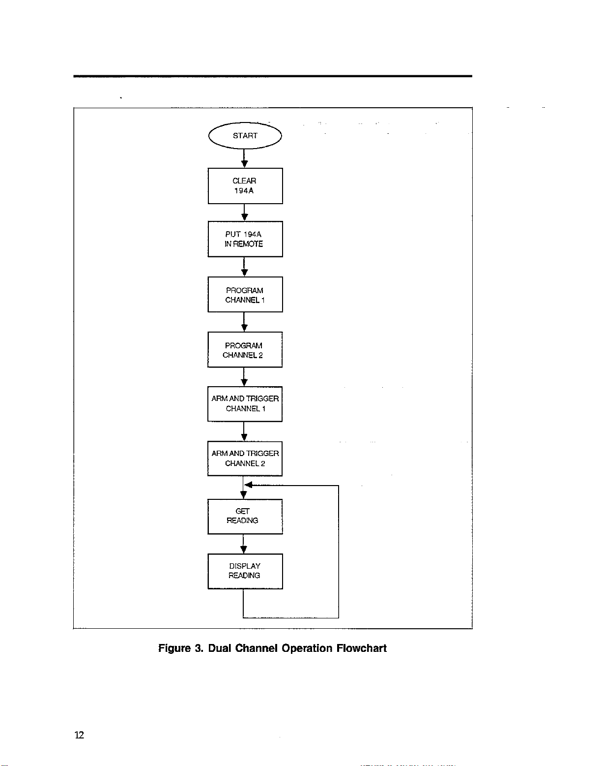
I I
t
ARM AND TRIGGER
CHANNEL 2
READING
I_!
Figure 3. Dual Channel Operation Flowchart
Page 13
Usually, an instrument is sent a command at the start of a program to return it to some default
state. In the program below, this operation is performed by sending an SDC (Stile&d Device
Clear) as follows:
This statement instructs the Model 194A to assume its power-up (setup 1) configuration.
Next, we must make certain that the instrument is in remote before sending programming
commands as follows:
3M REMOTE 76’3
Now we can program channel 1 and channel 2 as required. For channel 1, we will select
the 32OmV range (Rl) and TRMS function (F2) as follows:
In a similar manner, channel 2 is programmed for the ZOOV range (R4) using the average
function (Fl):
In both cases, you will note that the channel select (C) command is included at the fronts
of the command string containing range and function commands, followed by an execute
(X) character to assure proper channel selection. (Note that the X immediately after the C
command is not required, but it does no harm).
At this point, we have programmed both channels; however, since the range and function
were changed, we must arm both A/D converters. First, for channel 1, we have:
Again, each command string includes the channel selection command prior to the trigger
command that arms the AID converter. Here again, the immediate trigger mode vZ6) is used
so that no further triggering is necessary to start the AID converters. With other trigger sources,
you will be required to apply the necessary trigger stimuli to start the A/D converters after
arming them.
Now that both A/D converters are running and readings are being processed, it is a simple
matter to set up a loop to request and display readings:
Page 14
This loop repeats indefinitely, with one reading per loop accessed and displayed.
RUNNING THE PROGRAM
1. Enter the program into the computer.
2. Press the computer RUN key tostart the program.
3. The program will send the commands to the instrument and then request readings from
the Model 194A. Note that data will alternate between channel 1 and channel 2 depending on which channel has the most current reading.
USING ONE CHANNEL
In order to use only one channel, program the other channel for an unused trigger source.
For example, to turn off channel 1, modify line 60 as follows:
6’3 OUTPUT 7B9j 6 g tCl:XTTK’ 3
Similarly, to disable channel 2, modify line 70 to read:
In both instances, the disabled channel is programmed for the external trigger mode. Thus,
in order for that~channel to remain disabled, no trigger signal can be applied to the trigger
input~for that channel. Another way to disable a channel is to use T27 which causes only
one trigger; no further triggers will oCcur even with external triter input noise.
SELECTING CHANNEL OUTPUT
As discussed previously, you can dictate which channel has the current-output by programming the desired channel for a particular function (so&as average), and then immediately
requesting a reading. In order to demonstrate this process, eliminate lines 80-110 from Program 2, and add the following lines:
20 OIJTPUT 789; L dCIFiX”
90 ENTER 7B9; ReadingB
1BW PEIMT &adiigB
110 OUTPUT70’3; 6 GCZFlX””
12’3 EMTEE 7W3; Readings
130 PEIMT Readings
i4k3 GOTO 80
159 END
! Compute channel 1 reading.
! Get channel 1 reading.
! Display channel 1 reading.
! Corn ute channel 2 reading.
! Get jtl annel2 reading.
! Display channel 2 reading.
! Repeat
14
Page 15
With these modifications, the computer display will alternate between channel 1 and channel 2 readings. Note, however, that one channel may still overwrite the other if there is a
large difference in processing speed between the two channels.
Program 2. Dual-Channel Programming
10
OIM ReadlngBlSOl
20
CLEAR 709
30
RErlOTE 709
40
0UiP”T 709;“CIXRIF:X-
50
0”iP”T 709i”C:XR4FiX”
60
OUTPUT 709i”CIXT?fiX’
70
OUTPlJT 709; ~CZXT26X”
ENTER 709,Readimp
PRINT Reading*
GOT” 80
TN,,
oincnalo” reading string
Return the 194.4 to default conditions
Put the 134 into renotc mode
Program chl far the 320mU range and TRMS
Program ch2 for the 200” range and Rverags
Am channci I
Am channel 2
Get a reading fron the !94A
Print the rcadlng
ReDeat
I5116
Page 16
SINGLE AND CONTINUOUS
TRIGGER ARMING
PROGRAMMING CONCEPTS
l Sending the arming command ~once with continuous arming.
l Sending the arming command before each trigger with single arming.
l Triggering the measurement with single and continuous arming.
PROGRAMMING CONSIDERATIONS
Before the Model 194A will take a measurement, it must be triggered with the stimulus determined by the selected trigger source: immediate, input signal, external, other channel, or
an IEEE-488 GET, X, or t& command. However, it will notrespond to a trigger unless the
A/D converter is first-armed and ready for a trrgger.
Basically, there are two A/D arming modes: single and continuous. With single arming, the
A/D converter must be re-armed before each trigger. However, in continuous, the A/D converter need be armed only once, as the converter is automatically rearmed after each
measurement.
Over the IEEE-488 bus, arming takes place when the programming command for that particular trigger mode is received. For example, sending l3X (single arm, trigger on GET), arms
the A/D converter. Once armed, the measurement will be initiated when GET (Group Execute Trigger) is received. In this instance, the T3X~command must be sent before each trigger to arm the A/D converter. In contrast, if using continuous GET (TUC), you need send
the command only once before the first trigger, after which the A/D converter will automatical-
ly rearm itself after each measurement.
To summarize, there are several steps to programming and using triggers:
1. Fit select the channel to be armed and triggered. For example, to select channel 1, send
ax.
2. Send the command to select the trigger source and arm the A/D converter. For example,
toselect single, GET, send ‘l’3X.
3. Repeat steps 1 and 2 for the other channel, if desired.
4. Apply the necessary trigger stimulus to initiate the measurement. For example, issue the
GET command to initiate the measurement.
5. If you have selected a single arming mode, remember to re-arm the converter before each
trigger by sending the appropriate command over the bus.
Page 17
PROGRAM OPERATION
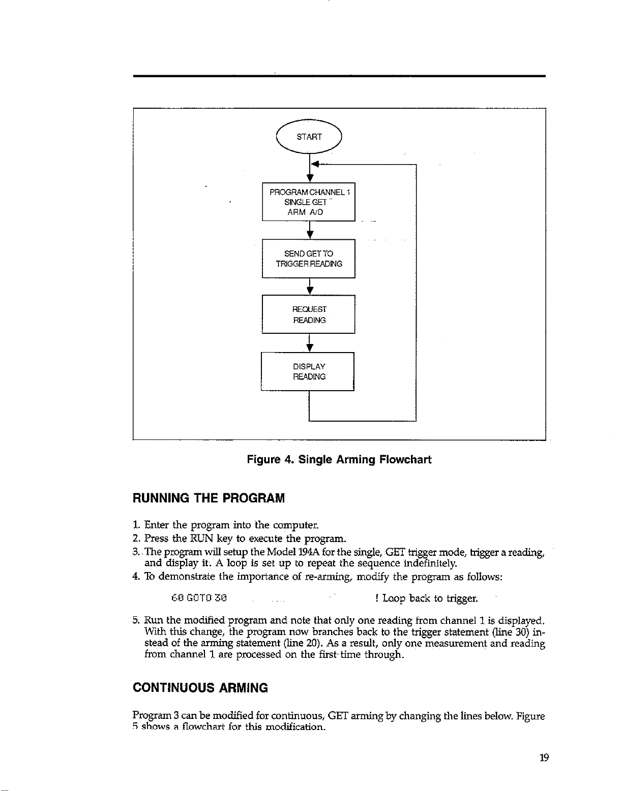
Program 3 below demonstrates single arming using the GET trigger source. Figure 4 is a
flowchart of the program.
Once the unit is in remote, we can program the trigger source and arm the channel 1 A/D
converter as follows:
In this particular instance we have selected the single arm, GET trigger mode (T3X); after
the command is sent, the A/D converter will be armed.
Now that the A/D converters is armed, we can trigger a measurement by sending GET:
The next two lines request a reading from the Model 194A and display a reading on the CRT:
40 ENTER 709;EeadingS
5W PR I t.IT Readings
Here the incoming data string is stored in Readmg$.
One final line necessary to complete the loop is:
Note that this branch goes back to the line containing the re-arm (T3X) command because
a single-arm trigger mode is jn effect. If instead we had branched back only to line 30, only
one reading would be taken the first time through the loop.
18
Page 18
SENDGETTO
TRIGGER READING
Figure 4. Single Arming Flowchart
RUNNING THE PROGRAM
1. Enter the program into the computer.
2. Press the RUN key to execute the program.
3. The prc~gram will setup the Model 194A for the single, GET trigger mode, bigger a reading,
and display it; A loop is set up to repeat the sequence indefinitely.
4. To demonstrate the importance of reaming, modify the pmgram as follows:
60 GOTO 38 ! Laop back to trigger.
5. Run the modified program and note that only one reading from channel 1 is displayed.
With this change, the program now branches back to the trigger statement (line 30) in-
stead of the arming statement (line 20). As a result, only one measurement and reading
from channel 1 are processed on the fiist~ time through.
CONTINUOUS ARMING
Program 3 can be modified for continuous, GET arming by changing the lines below. Figure
5 shows a flowchart for this modification.
19
Page 19
20 O,JTPClT 70’3; 6 ~I:l:<T;?)<’ J ! Program continuous arm, trigger on
GET.
co GOT0 30
Upon running this program, you will note that repeated readings appear on the computer
display. Now, however, it is n&necessary to %rmthe converter each time--merely trigger
it--to obtain each reading.
PROGRAM CHANNEL 1
CONTINUOUSGET.
ARM A/D
! Branch back to trigger statement.
SEND GETTO
TRlGGERREADlNG
Figure 5. Continuous Arming Flowchart
Program 3. Arming and Triggering
10 REMOTE 709
20 OUTPUT 709;‘C,XT3X~
30 TRIGGER 709
40 ENTER 709,4ead,ng5
50 PRINI RPsdlng*
60 FOTO 20
70 END
20
Page 20
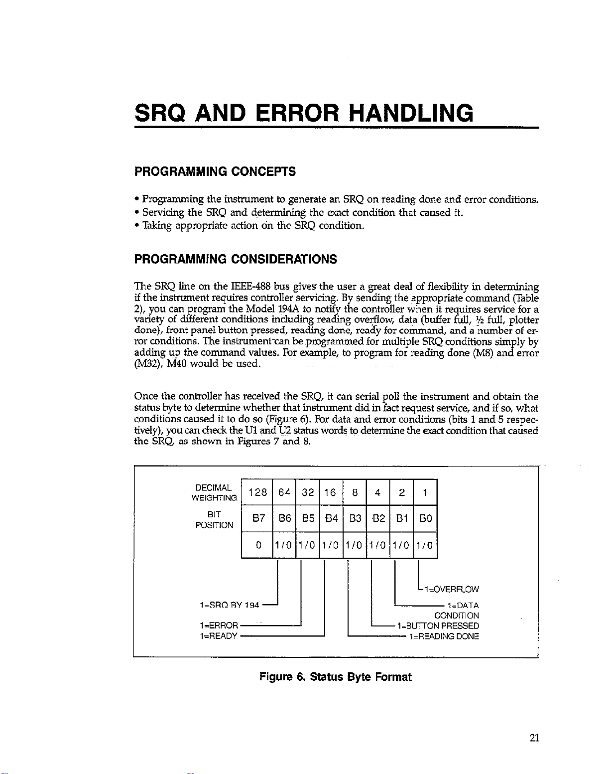
SRQ AND ERROR HANDLING
PROGRAMMING CONCEPTS
l Programming the h@ument to generate an SRQ on reading done and error conditions.
l Servicing the SRQ and determining the exact condition that caused it.
l Taking appropriate action tin the SRQ condition.
PROGRAMMING CONSIDERATIONS
The SRQ line on the IEEE488 bus gives the user a great deal of flexibility in determining
if the instrument~requires controller servicing. By sending the appropriate command (Table
2), you can program the Model p4A to notif
variety of different conditions including rea
done), front panel button pressed, reading done, ready for cotiand, and a number of er-
ror conditions. The instrument-can be programmed for multiple SRQ conditions simply by
adding up the command values. For example, to program for reading done (M8) and error
(M32), M40 would be used.
Once the controller has received the SRQ, it can serial poll the instxument and obtain the
status byte to determine whether that instrument did in fact request service, and if so, what
conditions caused it to do so (Figure 6). For data and error conditions (bits 1 and 5 respectively), you can check the Ul and U;? status words to determine the exact condition that caused
the SRQ, as shown in Figures 7 and 8.
the controller when it re uires service for a
kg oveflow, data (buffer ?i.zll, ‘/2 full, plotter
DECIMAL
WEIGHTING
BIT
POSITION
Figure 6. Status Byte Format
21
Page 21
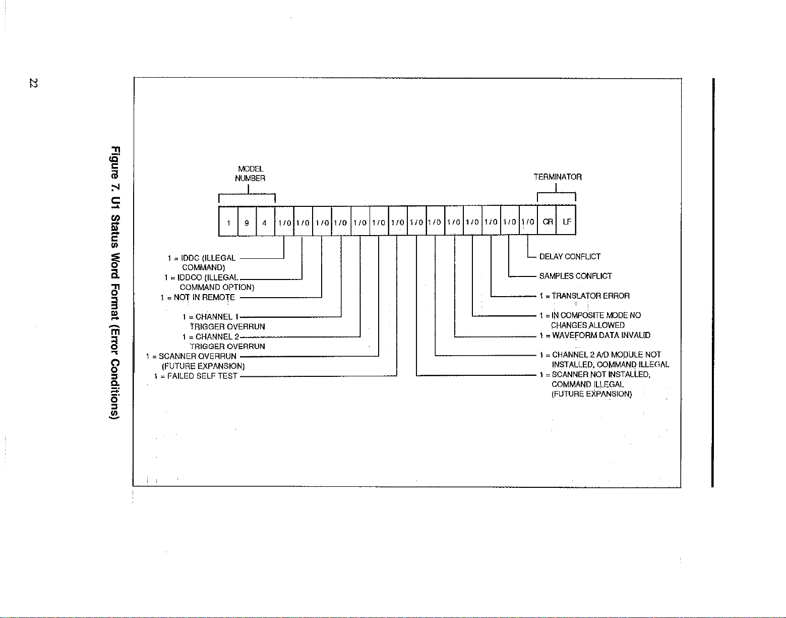
I
I I I I I I I
I119141~ I I I I I I I I I I I I I, I I
1 = IDDC (ILLEGAL -
COMMAND)
1 = IDDCO (ILLEGAL
COMMAND OPTION)
M3DEL
NUMBER
I
TERMINATOR
I I ’
I I I I I I I I I I I I
1/o 110 110 l/O 110 l/O 110 1/o l/O 1/o 110 l/O 110 110 CR LF
SAMPLES CONFLICT
I= iRANSLATWi ERROR
COMMAND ILLEGAL
[FUTURE EXPANSION)
I
I
I
Page 22

Basically, there are two different methods the controller can use to detect the SRQ: interrupt
and po!.ling. The interrupt~method is by far the more versatile, since it is possible for the
controller to perform other tasks until the instrument requests service. With the polling
method, the controller must periodically check the status of the SRQ line to determine if
the instrument requires service.
Table 2. SRQ Commands
Description
SRQ disabled
Reading overflow
Data (Buffer full, Yz full, plotier done)
Front panel button pressed
Reading done
Ready for new command
Error (IDDC, IDDCO, tiot in remote, trigger overrun, channel 2
not installed waveform invalid, composite mode, translator,
samples 07 delay conflict.
*Pro am multi
M4 X for SR
f cf
le SRQ conditions by ad&g individual command values. For example, send
on error, and when reading is done.
KXEL
NUMBER
BUFFER HALF FULL
1 = PLOTTER
DONE
Figure 8. U2 Status Word Format (Data Conditions)
PROGRAM OPERATION
TERMINATOR
CONVERTER ARMED
1 i CHANNEL 1AX?
CONVERTER ARMED
Program 4 below demonstrates interrupt SRQ handling and error status checking. The pro-
gram can be broken into two sections: initialization and main task, and error handling. Figure
9 gives a flowchart of key sections of the first part of the program, while Figure 10 outlines
the error handling routmes.
23
Page 23

Highlights of the first part of the program include:
1. The Model 194A is returned to default by sending an SDC (line 20).
2. The unit is serial polled in order to clear a peiiding SRQ (line 30).
3. The service routine that will detect andservice the SRQ on an interrupt basis is then defined
(lines 70-100).
4. Channel 2 of the instrument is disabled by sending czT7X (line 120).
5. The user command string is requested and sent to the instrument (lines 130-150).
6. The instrument is programmed to generate~an SRQ on reading done or error conditions
by sending the command M40X (line 160).
7. The unit is programmed for continuous, GET trigger by sending T2X (line 770). Note that
the channel 1 A/D converter will continuously arm in this mode; it-will not be necessary
to re-arm the converter before every trigger.
8. Since the A/D converter will be armed at this point, it is only necessary to send a GET
command to trigger the unit and initiate the measurement (lie 180).
9. The user’s main task then begins execution. In thjs instance, the “main task” is a simple
incremental counter to indicate that the propam is looping (lines 200-220).
When executing, the program will stay in the main task until an SRQ is detected. When
an SRQ occurs, the program will service the SRQ as follows:
1. The Model 194A is first serial polled to obtain the status byte (line 250).
2. Next, the state of bit 6 in the status byte is tested to determine if the SRQ was, in fact,
generated by the Model 194A (line 270). Jf this bit is set, the program will continue checking other bits in the states byte. Otherwise, the program returns tu the main task. This
steps is essential only when more than one instrument is on the bus.
3. Bit 5 of the status byte is then checked (line 290) to determine if an error condition occured. Jf so, the program branches to a subroutine (beginning at line 350) which requests
the Ul error word and then tests appropriate bits in the error word to determine the nature
of the error. A suitable message is then displayed if an error is found, and the program
then halts.
4. If no error is found, the program tests the state of bit 3 in the status byte (line 310). Jf
this bit is set, a reading is ready tom be processed, and the program branches to a subroutine
to request and display a reading, and trigger a new one (liies 530-570). The subroutine
then returns to the use& main task.
RUNNING THE PROGRAM
1. Enter the program into the computer.
2. Execute the program by pressing the RUN key.
3. At theco mmand prompt; type in the desired string command. The command string should
contain only A/D programming commands (range, function, filter, coupling, sample, and
rate). In order to allow sufficient time for the main task to run, choose a sampling rate
and number of samples resulting in a measurement duration of several seconds. For example, to program a sampling interval of lmsec and 3ooO samples, enter “SOJE-3NOJOCOX”
(quotes must be used because of the commas).
4. The computer will then display the incremental counter to show that the main task is
running.
24
Page 24

5. Once the Model 194Abas taken its measwmnent~and processed the reading, the unit will
generate an SRQ, and the read&g will be displayed.
6. To demonstrate an SRQ-generated error message, type in an illegal command at the command prompt. For example, type in ElX; note that the computer displays the IDD~C ERROR
because E is an illegal device-dependent command letter.
START
i>
SEND DNW
DEFINE BRANCH AND
ENABLE INTERRUPT
Figure 9. Program 4 Flowchart (Initialization and Main Task Section)
25
Page 25

RE(xIEST ERROR
r-2-l
SERlAL POLL
Figure 10. Program 4 Flowchart (SRQ and Error Handling Section)
26
Page 26

USING POLLED SRQ
The program can be modified for polled SRQ by making the modifications below:
1. Remove lines 70, SO, 90, lOO,- and 550.
2. Add the following lines to the program:
211 STATILlS 717; Bus-lines
212 IF BIT IEusJines)=l
THEN GOSUH Service_routine
! Read bus lines.
I Check SRQ~ bit status.
With this modification, the controller must check the status of the SRQ line each time it goes
through its main task loop. Although from a user’s standpoint the program may appear to
operate the same, the additional controller overhead necessary for p4led SRQ uv3y becomq
restrictive in larger applications.
Iii0 OUTPUT 7091 -M40X”
(
Page 27

Program 4. SRQ and Error Handling (Cont.)
28
Page 28

BINARY DATA TRANSFER
PROGRAMMING CONCEPTS
l Data transfer speed considerations.
l Transferring binary data from the Model 194A to the computer.
l Converting binary data into displayable form.
PROGRAMMING CONSIDERATIONS
When a relatively large number ofsamples must be transferred from the Model 194A to the
computer, speed becomes an important consideration. The binary transfer mode of the instrument can significantly reduce the amount of time it takes to send 8 given amount of data
from the iwtrurnent to the computer. Binary transfer speeds up this operation for two reasons:
(1) the Model 194.4 is not required to process the data before s&ding it out, and (2) fewer
bytes are transferred per sample in the binary mode.
In order to take full advantage of binary transfer speed, the computer must be ca able of
transferring at a rate at least as high as that of the Model 194A--approximately 9 I& bytes
per second in binary mode. The HP9816 used for the example program below can operate
at rates as high as l30K bytes per second using fast handshake transfer, but other controllers
may require use of DMA transfer to operate with sufficientspeed. In any event, the advan-
tage to using binary transfer can be seen by comparing the time necessary to~transfer 1000
samples. In binary mode using fast handshake, these
65msec as opposed to 15 seconds required when using ASC
ment. (using an HP9816 computer).
sam les
can be transmitted in only
E
transfer and the ENTER state-
The general binary formats for the G6 and G7 modes +we shown in Figure 11. In addition
to the one or two bytes for each sample, a~~&byte status word and byte count (G7 only) is
added to the front of each byte sequence. The statis word contains unportant information
such as range, channel, function, as well as the exponent for the data. In order to display
the data, it must first be converted into ASCII form, as demonstrated in Program 5 below.
PROGRAM OPERATION
Program 5 below demonstrates fundamental concepts for obtaining bii data and converting
it into displayable form. Figure I2 shows a general flowchart of the program.
Program highlights include:
1. The program first initializes variables and Ii0 paths (liies 10-70).
2. The instrument is then programmed for the waveform mode (FO), number of samples (NO),
sampling rate (SO), binary data format (G7), and reading buffer disabled (lines 80-140).
29
Page 29

A. GS
STATUS WORD 4 wn3
SEE BELOW
B. G7
MSB LSS I
5-5-+ww5----LT-l
BYTE STATUS WORD SAMPLE SAfvwLE~ SAMPLE SAMPLE
COUNT (CBYTES) 1 2
(I-64K) SEESELOW
2 3 4 MSS LSB MSB LSS MS8 LSS MSS LSS I..+$q
1 j ; j j / j j 1 RANGE
’ ’ ! ! ! ! ! sEESELOwl
1 = 1 S-BIT MODE
0 -8.SIT MODE
1 =ZERCED
RANGE CHPlNNEL
*-Em MODE: EACH BYTE IS A SEPARATE SAMPLE.
lS.S,T MODE: BYTE 1 IS MOST SIGNIFICANWYTE, BYTE 2 LEAST
SIGNIFICANT.
3 N
(BYTE PER SAMPLE IN 8.SIT MODE;
CHANNEL 1 ~TusED 1 FUNCT0N 1 EXPONENT
,sEEBELow SEE BELOW 125 COMPLEMENTl
I I
I
S!MJLE
F”NCTlON
EOI
1
IWTF ,
lN”ALlD NUMERIC: 1 = READING IS lN”ALlO
SUFFER IN”ALID: 1 = MEASUREMENT SUFFER CONTAINS lN”ALlD SAMPLE
OVERFLOW: I= READING SAMPLEO”~RFLOWED
WAVE FORM IN SUFFER: 1= MEASUREMENT SUFFER CONTAlPJSAWA”EFORM
8HG SIT MODE: 1 = <S-SIT: 0 E S-SIT
ZEROED: 1 =zERO IS ENABLED
Figure 11. Binary Data Formats
30
6
7 0111 INTEGRAL
~8 1000 RECALL
0110 STANDARD DEVlATlON
Page 30

3. Next, the program performs a test to see if the reading is done (lines 160 and 170). This
test is performed by serial polling the unit and testing the state of bit 3 in the status byte
(the reading done bit). If the bit is cleared, the reading (and thus the measurement) has
not been completed, and the program remains in the loop until bit 3 is set, indicating
that a reading is available.
4. Once it-has been determined that the reading is complete, the fast handshake transfer
is performed tom read the binary data into a computer I/O buffer (lines X30-221). In order
to properly terminate the transfer, it is necessary to know how many bytes are to be transferred. This value is determined from the number of samples programmed, as well as
whether the data is in eight or 16-bit format. A value of six is added to the total byte count
to account for the count and status bytes.
5. Next, the byte count and status are read from then I/O buffer and placed into numeric
variables (line 240). In this case, the firsts two bytes represent the byte count; while the
last four bytes contain Model 194A status information, as shown in Figure 11(c).
6. Binary data is then read from the I/O buffer into-a numeric array, (line 770 or 280). The
transfer is in byte @-bit) or word (X-bit) format,
strument stores S-bit-data at rates above lMlk&).
ending on the sam
R
ote that the end o P
ling rate (the inthe data for this
de
transfer is determined by EOI.
7 The binary data is then converted into displayable form (lines 350-410). This subroutine
must take into account the weight of each bit. In the g-bit mode, the bit weight is 256,
while in the 16-bit mode, the bit weight is 1.
8. The data is then scaled according to range by using~ the range information located in byte
2 of the status word..Since this range information is located in the most significant nibble,
it must be converted by ANDing with 48 and then dividing by 16. Figure 13 outlines this
conversion process.
~~.
9. Once final test is made to determine the status of the overflow bit located in byte 1 (lines
520-570). A normal or overflow reading message is determined by the status of this bit.
31
Page 31

PROGRAM AND
TRlGGER 194.4
GEM GEM
SAMPLE SAMPLE
1 1
CONVERT CONVERT
SAMPLE SAMPLE
1 1
DWLAY DWLAY
SAMPLE SAMPLE
32
Figure 12. Flowchart of Binary Transfer Program
Page 32

I
AND
RANGES
r-l
CHANNEL
0 0 ~1 1 0 0 0 1 ~BME 2
0011 0 0 0 0~ ~(~~4810)
0011
i
A. ANDing WITH 48, o TO MASK OFF UNWANTED BITS
000000E
--a
~8. DIVIDING BY 16 SHIFTS RANGE BITS ~FOIJR PLACES
TO RIGHT.
0 0 0.0
RANGE
Figure 13. Converting Byte 2 Range Bits
RUNNING THE PROGRAM
1. Enter the program into the computer.
2. Execute the program by pressing the RUN key.
3. Apply a DC voltage oft less tbti 32OmV.
4. When the prompt for number of samples is displayed, type in the desired value. For example, for 100 samples type in 100 and press the ENTER key.
5. When the computer prompts for the reading rate, type in the desired value. For example,
to program a lpec rate interval, type in ll?-6 and press ENTER.~
6. The Model l94A will now process a measurement and then display the individual samples,
including sample number and a message as to whether the sample is normal or overflowed.
With less than 32OmV applied, the reading should always be normal.
7. Increase the applied voltage to 5oOmV and NIX the program again. Note that the overflow
message is now displayed because the 500mV applied signal is above the maximum input
voltage of the 320mV range.
8. Change the Rl range command in line 130 of the program to RO. This change will program
the Model 194A for autorange. Ream the program several times with different applied
voltages between 200mV and 200V and note that displayed data is automatically scaled
according to range.
33
Page 33

Program 5. Binary Data Transfer
10 Initializegrog: !
30 INTEGER 8( 32000)
40 REAL A
41 OIM A$[320001 SUFFER
50
60
70 OUTPUT KBOICHR$( 2% )&CHR8(75 )i
30 I”li ielize~1~S4: I
35
90
100
110
120
121
130
140
150 Test_reading:l
160
170
1B0 setup-tranefei: !
190
200
210 Perfarn-transf: I
211
212
220
ZZ,
230 Rend-statue:!
240
260 Read-data:!
250
270
271
280
281
290
300
310
320
330 STOP
340 convert: I
3G0
360
361
370
371
330
390
400
410
420
430
440
450
4G1
460
470
480
490
ASSIGN 80194 TO 703
WiGIGN @Suf TO BUFFER A$
REMOTE 703
PRINT “ENTER NUMBER OF SAPIPLES’
INPUT Samples
PRINT “ENTER RE&OING RRTE IN US <e.g IE-6)”
INPUT Pate
! Progren 194
OUTPUT 709;“F0R,NB,“&“ALs(S~~~~~,~~“S0.”6VALO(Rete~~.G7O0~.
OUT~PUT 709, ‘T27X”
S=SPOLLC 709 1
IF SIT<S,3)=0 THEN GOTO 160
IF Rate/l.OE-5 THEN Numb&r-bytes-l
IF Rate:,, .0E-5 THEN Nunhcr-bytes-2
! Transfer 194pI Data us‘ng fast hand,haks. Te~ll how maw
bytes are ta be tranafered.
TRANSFER 00134 TO WufiCOUNT ~(Nunber_bytes+Sanpis.)t6,WnTT
: Read 194A status fran buffer
ENTER Wuf USING ~X.W,B.B.R.B~;Count,Statual ,Stat~.Z.Statu.3,Statu.4
FOR Data=, TO Sample5
IF Ratei,.0E-5 THEN ENTER R&f USING ‘%.B”r3(0ata) I Read 8 bit word
IF Rate:,.0E-5 rHEN ENTER B&f USING ‘%.W*iE(Data) 1 Rea~d 16 bit word
GDS”9 canvert
PRTNT Oat a .Reading .Hessaoes
NEXT Data
SENO 7,UN1
A=BtOata)
IF Rate:, .“E-5 THEN Rij+weight-256
IF Rate,,.OE-5 THEN Bit-weight-1
IF Range-0 THEN Reading-R*i.OE-5
IF Range=, THEN Reeding=R*I.OE-4
IF Range-2 THEN Readlng=R*I.OE-3
IF Range-3 THEN Read,ng=R.i.BE-2
I Reserves storage for floatiig mint variable
I Goaub ta ravtina that converta raw binary
I DiFlenei0n tntcrxr
I Dlnaneio” buffar
~! *seign I/D path n*ne to 1946
I Rsalgn I/O path name to BUFFER
I Clear em-can
! Put 194R in renote
! ~PrOFlpt for tt w&npl+a
! Input * sanplea
! J+*np_t for rate
I Input rate
I Arm the 194A
I Perforn serial poll
1 Teat far reading done
( Oeterninc X bytea PCP aanele
! Detern~ne P bytes per ~anple
! fro,, buffer.
! from buffer.
! Dsteinlne bit we,pht for 8
! bit mode.
I Deternlne bit weight for 16~
1 bit node.
! et.tu.
1 Scale reading for.320V range
/ Scale reading for 3.~2” range
! Scale readying for 32V range
! Scale reading for 200” range
34
Page 34

Program 5. Binary Data Transfer (Cont.)
35136
Page 35

READING BUFFER OPERATION
PROGRAMMING CONCEPTS
l Fundamental operation of the reading buffer.
l Disabling the unused channel so that only desired readings are stored in the reading buffer.
l Triggering each stored reading indiyidually.
l Operation of the reading buffer pointer.
l Dumping entire buffer contents in one string.
PROGRAMMING CONSIDERATIONS
The reading buffer is a 100 location buffer into which processed readings can be stored as
they become available. By sending the appropriate command, you can operate the reading
buffer in a linear configuration (Qi) or a circular mode (QZ). With a linear buffer, the instrument will continue to store readings until all 100 locations are full and then stop storing until
the buffer is completely emptied. With the circular buffer, the instrument will store 100
readings and then stop. As old readings are taken from the buffer (in oldest to newest order),
new readings will be stored in the empty locations.
Since a single lOO-location reading buffer is shared by both channels (dual-channel units),
care must be taken when reading the buffer to determix the source of the dataIf both channels are running, data will be stored in the buffer on an as-available basis. Thus, to determine which channel is the data source, you should check the channel suffii (Figure 2) on
the reading string. Of course, you can also turn off an unused channel by programming
for a trigger condition that~will note be met. For example, to turn off channel 2, send C2XT7X
over the bus. Doing so will make certain that data comes only from the desired channel.
The way the buffer fills will depend on the programmed trigger mode. In the immediate
mode, the instrument will fill the buffer without requiring additional triggers. However, in
the remaining trigger modes, yen ,must supply one trigger per measurement in order to fill
the buffer.
Once your data is stored in the buffer, there am several ways to access it. with the GO through
GZ data formats, one buffer location will be sent with each request. However, you can also
dump the complete buffer in one operation by using G4 or G5. Remember, however, that~
the computer input buffer or string must be dimensioned large enough to handle all the
bytes in the data string.
By using the B3 command, you can dictate how many oft the reading buffer locations will
be sent. Simply use B3,nX, where n represents the last location that will be transmitted.
For example, if you send the command B3,2OX, locations 1 through 20 will be transmitted
when requested.
37
Page 36

It~is important to clarify the operation of the buffer location suffix, which is shown in Figure
2. This value does not represent the buffer location number; rather, it shoti the number
of readings left in the reading buffer after accessing this particular location. For example,
assume you send B3,2OX to set an end pointer of 20. The~first location to be sent will be number
1, but the suffix will show 0019, meaning that there are still 19 locations left to access. This
value will decrement once per buffer location until it shows a value of 0000 with the access
of the last buffer location.
PROGRAM OPERATION
Program 6 below demonstrates fundamental operation of the reading buffer. Figure 14 is a
flowchart of the program.
Basically, the program operates as follows:
1. The string called Readi& is dimensioned to hold 2,KlO bytes (line lo), and the unit is
placed in remote (line 20).
2. Both channel 1 and channel 2 are disarmed by sending T7x to then appropriate channel
(Iines 30 and 40). Channel 1 is disarmed to ensure that no readings are being processed
when the reading buffer is turned on; othqise, undesired readings will be stored. Channel 2 is turned off to avoid storing channel 2 readings at ail.
3. Channel 1 is programmed to take 10 samples (NO,lO) per measurement at the maximum
rate of l* (SOJE-6) by line 50.
4. The reading buffer is then enabled for the~linear configuration by sending QlX (line 70).
5. Next, a lOO- point loop is set up to arm the A/D converter and trigger each measurement
(lines 80-I.&. Each t rme through the loop, the A/D converter is armed by sending ‘I3X,
and a measurement is then triggered by GET. As each reading is processed, it is stored
in the reading buffer in the next sequential location.
6. After the loop is complete, the unit is programmed to dump the fast 20 readings of the
reading buffer in one long string (line l30)Jhe G5 command tells the instrument to output all available buffer locations at once, while the B3,20 command limits the output to
the fast 20 locations only (Iocations l-20).
7. Finally, the reading string is requested and displayed on the computer screen (lines l6O-170).
RUNNING THE PROGRAM
1. Enter the program into the computer.
2. Press the RUN key to execute the program.
3. The program will send commands to the Model 194A, and 100 readings will be stored
in the reading buffer.
4. Once storage is complete, the complete reading string will be displayed on the computer
display. Note that the reading number suf@es decrement ram 19 down to 0 throughout
the reading string. As pointed out earlier, this number represents the number of readings
left to access at that~point--not the buffer location number.
38
Page 37

Figure 14. Flowchart for Reading Buffer Program
39
Page 38

Program 6. Reading Buffer Operation
I0
OIM RaadlnQG~20001
20
REMOTE 703
30
OUTPUT 709:‘CIT7X”
40
OUTPUT 709i”CZT,X’
50
OUTPUT 703i”CIN0.,050,iE-6X”
60
70
OUTPUT 703:“QIX”
80
FOR I-1 TO 100
OUTPUT 709i”T3X”
30
I00
TRIGGER 703
110
120
NEXT I
OUTPUT 7a3,‘GSB3.:0X”
130
140
150
160
ENTER 709iReadrngB
170
PRINT Readings
160
END
I oinanaion readings
! Put the 1948 in rcnotc
! Turn off channel 1
f Turn off channel 2
! Program rats and * sanplca for
! channa, 1.
! Enable linear bvffer
1 Take I00 readinps
.I Program trfpper mode and arm AI0
! charm*, I.
! Trrwer the 1348
! Triggsr another reading
! Program 194R to ,end
! readings 1-20
!
! Read buffer Iocatlons I-20
lKPFi”i rcading$
40
Page 39

USING TRANSLATOR
PROGRAMMING CONCEPTS
l Using Translator tom make programs easier to read.
l Instrument emulation using Translator.
PROGRAMMING CONSIDERATIONS
The Translator feature allows you to substitute a group of ASCII characters for a device-
dependent command string. Basically, there are two chief reasons for using this feature: (1)
to make programs more readable, and (2) to emulate the operation of other instruments.
Translator words are defined with the ALIAS command by including the defied word along
with the associated device-dependent-comaqd string. For example, to define the word
SAMPLES to prograti 1000 samples, the ftiiiowing would be used:
Note that spaces are included to delimit the ALIAS command, the defined word (SAMPLES),
and the device-dependent command (NO,lOOOX). Also, the definition string must be terminated with a semicolon.
Once Translator words are defined, using them is simply a matter of sending them in place
of device-dependent commands, for example:
In this case, the word SAMPLES would program 1000 samples because SAMPLES was
previously defied as NO,lOOOX.
MAKING PROGRAMS READABLE
Program 7 below gives an example of how Translator can be used to make programs more
readable. Figure 15 is a flowchart of the program.
Page 40

SEND SELECTIVE
DEVICE CLEAR
Figure 15. Flowchart for Program 7
Program Operation
Key points of the program include:
1. The variable Voltmeter is defined as 709 for use in subsequent OUTPUT statements (line 20).
2. The inshument is then returned to default conditions tid placed in remote (lines 30 and 40).
3. Next, the Translator words are defined by using the ALIAS command (lines 50-100).
4. Test 1 is then executed by sending the appropriate Trkslator words to program the various
operating modes (lines 120-170).
5. In a similar manner, Test 2 is performed by programming the &trument (lmes 190-240).
42
Page 41

Running the Program
1. Enter the &xogmm into the computer.
2. Press RUN to execute the program.
3. The program wi!.l then send Translator words to the inshument to be defined. Two different readings should appear on the computer CRT, one each for Test 1 and Test 2.
INSTRUMENT EMULATION
Program 8 demonstrates the use of Tran$a@’ to emulate the TRMS measurement of an AC
waveform. Notes that TCR4? is the command string that is to be emulated by the Model 194%.
This command selects RMS, 1OVAC range, and DC coupling of the DVM being emulated.
Figure 16 gives a flowchart of the program.
Program Operation
1. The Translator word is first defined (line ~3).
2. The instrument is placed in remote (line 10).
3. The defined Translator word (TCR4?) is then sent to the instrument (line 20).
4. Finally, a loop is set up to request and display 10 readings (lines 40-70).
Running the Program
1. Enter the program into the computer.
2. Apply an AC signal of approximately 1OV RMS to the instrument INPUT jack.
3. Press the RUN key to execute the program.
4. The program will send the necessary Translator definition command to the instrument;
program the instrument accordingly, and then request and display 10 readings.
43
Page 42

DEFINE TRANSLATOR
bm=a~
4
PUT 1~94A
INTOREMOTE
4
PROGRAM ~194A TO
EMULATE D”M
USING TR4NSLATOR
GET READING
c
DISPLAWEADING
44
Figure 16. Program 8 Flowchart
Page 43

Program 7. Using Translator for Program Readability
10 ProQram-aetupL
“a,tneter=709
20
CLERR Voltmeter
30
40 REMOTE “altmcter
OUTPUT Voltneteri”RLIA5 ZERO CIZ4X :” 1 Define trans1a+or word
50
OUTPUT “oltneteri’ALIA5 SETUP1 CIXF3R311X :” I 0efine translator word
60
OUTPUT “oltnetcrr”RLIAS SETUP2 ClXFiXRZX i- I 0efinc irans,ator ward
70
OUTPUT “o,tneter,“ALIAS 1000SAMPLES N0.1000X i-
80
DUTPU, “oitneter;‘ALIRS ARIl T2GX /-
90
OUTPUT “oiineier;“ALIRS OISPIBLECHZ CZXT7X i’l I Define translator word
I00
II0 Test-l:,
OUTPUT Uoitnettr;‘OISABLECHZ”
120
OUTPUT “altnetsr,“SET”PI’
130
OUTPVT “oIincter:‘ZERO‘
140
OUTPUT “01tmcteri’etR”‘
150
ENTER Uoltmetcr;ReadlnaB
I60
PRINT RcadlngB
170
180 rest-z: 1
DUTPUT Uoitmeterr”SETU~2”
190
OUTPUT Uoitneteri’l000SAMPLES
260
OUTPUT “oiinctcri “ARM”
210
ENTER U~ltmeter~Rc~din~S
220
230 PRINT r?.adinq%
END
240
!~Oaflne 194.A~ address
!LReiclrn to default
I Pui 194A rn rcmoic
I Define trans1atar word
I Define translator ward
Program 8. Using Translator for Instrument Emulation
I I Line 3 translates the DVM commands to 134A cmnanda.
O”TP!,T 709,‘ALIAS TCR47 C2TiXC1F:R3G11050,i66.7E-6N0.l000T26X 8”
3
10 REMOTE 709
20 OUTPUT 709i”TCR4?*
30
40 FOR I-i TO 10 1 LOOP~~~l0 tines
50 ENTER 709;ReadinuB 1 Get readinp
60 PRINT Readiny)% 1 Print rcad,ms
70 NEXT i
S0 EN”
1 Put ovn I” rcnote
~~‘1 ~irooran D”M for cont‘nuaus node.
I
Rk *c ,DC coueled and Irn’J ranOC
45146
Page 44

USING EXTERNAL SAMPLE
TRIGGERING
l Using external sample triggering~ to test potentiometers.
l Fundamental graphing techniques.
l Combining two instruments on the bus.
PROGRAMMING CONSIDERATIONS
The external sample trigger feature of the Model 194A allows you to synchronize sample
collection to external events. By applying appropriate TTLcompatible pulses to the sample
trigger input, you can trigger each sample individually.
One possible external sample~tigger application involves testing for potentiometer linearity
using the basic setup shown in Figure 17. In addition to the Model 194A, additional equip-
ment is necessary: (1) a Model 220 current source, and (2) an optical encoder. The Model
220 sources current through the potentiometer, developing a voltage to be measured by the
Model 194.A. The optical encoder develops- the sample trigger pulses necessary to trigger
individual samples.
To run the test, the current source is Seth to the desired value, and the potentiometer shaft
is rotated, either manually, or by a motor. As the shaft rotates, the encoder develops sample
trigger pulses at precise increments of rotation (typically 1 to 2 degrees per trigger pulse).
At each rotational increment, the Model 194A measures the voltage across the potentiometer
and stores that value asp a single sample.
Once all samples are taken, it is a simple matter to compute the resistance at each point
from the measured voltage and the source current. Computed data can then be further
analyzed or graphed, as required. Program 9 below demonstrates basic techniques for
graphing such data.
PROGRAM OPERATION
Program 9 is written to perform the potentiometer test described above. Figure 18 shows
a flowchart outlining key sections of~the program.
Important program sections are described below.
1. The program is first initialized by clearing the screen and assign&I/Q paths (lines 20-70).
2. Next, prompts are given for the user to input degree increments, degrees of span, and
maximum potentiometer resistance (Iines 8030). From this information, the total number
of samples required is calculated based on the degrees of span and degree increments
(line 140).
47
Page 45

3. The Model 220 current and voltage compliance are then programmed, and the output
is turned on (lines ‘I70 and 180). In this instance, we are programming a current of 100/A
(l.OOE-4); to program a different current value, simply change the current variable in line
170 to the required value.
4. The Model 194A is programmed for the number of samples (based on the required number
computed), samplmg rate (166.7@ec), range (32v), function (waveform), data format (no
prefix) by lines 230-260. In this case, we ” using channel 2~with channel 1 disabled. To
use channel 1 instead of channel 2, reverse the Cl ax-d C2 commands in these three lines.
5. Now that the instrument is ready, the program prompts the operator to turn the potentiometer and then inputs all samples into an may called Reading (lines 310-360).
6. The plot routines are then initialiied (lines 380530).
Z The graph is labelled (lines 550-740).
8. Finally the resistance is calculated fmm the stored samples, and the deviation from nominal
is then plotted (lines 760-860).
HP9816
COMPCrrER
IEEE - 488 BUS
POTENTIOMETER
UNDER TEST
MODEL 220
MODEL 194A
EXTERNAL
SAMPLE
TRIGGER
INPUT
4
VOLTAGE
INPUT
A
SAMPLES
TRIGGERPULSES
3 4~
; _ _ _ _ - - - - q-,
OPTICAL
ENcorn
OUTPUT
MOTOR
CURRENT
SOURCE
Figure 17. Potentiometer Test Configuration (Set up for Program 9)
48
Page 46

POTENTIONETER
CALCULATE RESlSTANCE
AND DE”lATlON
PLOT
POINT
ALL
POlNTS ?
0’
Figure 18. Potentiometer Test Program Flowchart
N3
YES
49
Page 47

RUNNING THE PROGRAM
1. Connect the Model 220 OUTPUT and Model 194A VQJ-T&X INPUT t0 the potentiometer
being tested. Both lows should be connected twone end of the potentiometer, and both
highs should be connected to the wiper.
2. Mount the optical encoder on the potentiometer shaft, and connect the encoder output
to the SAMPLE TRIGGER inputs of the Model 1944 through the Model 1942 or similar
sample cable. Remember that the encoder must supply JTLcompatible pulses with a
duration of greater than 1OOnsec (samples trigger on the rising edge).
3. Connect the instruments to the IEEE-488 bus of the controller using suitable cables.
4. Be sure that the primary address of the Model 194A is set to 9, and that the Model 220
address is programmed for a value of 12.
5. Enter the program into the computer, and check it for errors. If a different current value
than 1004 is desired, modii line 170 accordingly.
6. Rotate the potentiometer to one end~of-its rotation.
7. Make sure the ABORT line on the Model 194A is set low (connect the black and white
wires on the Model 1942 Sample Cable together).
8. Execute the program by pressing the RUN, key.
9. At the prompts, enter the degree increments (the resolution in degrees of the encoder),
the total span of the pot in degrees, and the maximum potentiometer value.
10. When prompted to do so, smoothly rotate the potentiometer to- the opposite end of rotation. The instrument will collect samples as the potentiometer is rotated.
11. Once data is taken, the readings will be read into the computer array, and the graph will
be generated using the voltage data and current source value to compute the resistance.
The plot generated shows deviation from nominal (
as shown in the example of Figure 19. Note that a
this example, yielding a total possible rotatidn in excess of 6,000 degrees.
percent) versus degrees of rotation,
i
O-turn potentiometer was used for
50
Page 48

Figure 19. Potentiometer Test Example
51
Page 49

Program 9. Potentiometer Test
10 InltallzcJr~m:!
20
30
40
50
60
70
80
30 INPUT Oewee
I00
110
I20
130
140
150
160 Set-“p-z20:l
$70
I80
190
200
210 setup-i94a: !
*20
230
240
250
260
270
280
290
300 Buffer-fill:!
310
320
330
340
350 ENTER 709IRsadi”g(Cou”t)
360 NEXT Count
370 Smtlmoiot:~
380
390
400
4,0
420
430
440
450
460
470
480
490
500
510
520
530
540 Lcocl~dxIs: r
550
560
570
580 SIZE 3
590
GCLERR
OUTPUT KYD,CHR6(255)BCHR5(75)
ASSIGN @fl220 TO 712
ASSIGN 811194 TO 709
CLEAR 0Mi94
DIM RCCdi”Q( 10000)
PRINT “ENTER THE NUMBER OF DEGREES BETWEEN EACH REROiNG’
PRINT ‘“ENTER THE TOTAL NUMBER OF OEGREES OF SPAN”
INPUT Oegree~total
PRINT “ENTER MAX REYIYTRNCE OFPOT IN OHMS’
INPUT Rcsistencc
Sam~le.-Depree_totallDepres
0”TP”T KEO;CHRL(25~S)&CHRb(75)
Current-l.00E-4
REMOTE BUZZ0
OUTPUT @M220,“l”W,L5(Curre”t )&“V60FIX” ! Program 220 for voltage,
REMOTE 0N194
OUiPUT @rl194~;“clT7x’
OUTPUT 0M194; ‘C2SB.I .667E-4N0.‘&UAL$~Samples)L’X”! ~Progran channsi 2 for
OUTPUT ~~194:“CZXGlR3F0B0T27X‘
PRINT “TURN POT”
FOR Count-1 TO 5amples
GRAPHICS ON
OUTPUT KBO:CHRS<255 >&CHR$(75)
GiNiT
PLOTTER IS 702 ,“HPGL’ PLOTTER IS 702 ,“HPGL’
CSIZE 7 CSIZE 7
NO”E 5.90 NO”E 5.90
LRBEL~” nodal 194A Potentiometer LRBEL~” nodal 194A Potentiometer
CSIZE 4 CSIZE 4
WOVE 40,10 WOVE 40,10
LABEL -Degrees of Rotation’ LABEL -Degrees of Rotation’
MOVE 5.15 MOVE 5.15DEG DEG
LOW 90
LABEL v): Ocviatic” From Non~nal’
“IEWPORT 20,100.20,70
GRID i0,10,0,5R,l,,,I
VIEWPORT 20, l00.20,70
WINDOW 0,oe~rcs~total,-200,2~0~0
CLIPS OFF
FOR Label-x-0 TO Degree-iota1 STEP-1000
!~Clear praphics display
! C1s.v screen
I AsciQn II0 path “ame to 220
! Resign I/O path name to 194A
! Return ,946 to 8 know” state
! Dinension reading
! In,mt degree
1 Inpl&Dcpree-total
! Input rcsiatanct
/ Calculate ““nber of sanelss
! Clear ccrecn
1 Ocfinc test cwrent value
!~Put 220 in remote node
!
currant and operate nods.
! Put 194A in renots nods
! Turn off channsi 1
I
! Program channel 2 for orefix and
I
suffxx off.3Z” ra”Qc. wavefor”
I~ .nodc. clear uavcform output and
I
cinglc arming co”ti”“ous trtgger.
! Pronpt to start turning pot
! Define number of readings
! Controller wtll Wait for buffer to
I fill
I Get ,946 readlno and wt into array
! Repeat fir next reading
!~ Turn graehics dlaolay on
! ClsG sCre.5”
/ ‘Set grap~hic varrables to default
! Select plotting device
! set character CfLC
1 nave pen
Test’
! Set character size
1 “0”s pen
I Draw label
!KMova pan
! Select deprees c5 unit of FlCCS”CC
I Defin* mole at which-i&al is’drawn
! O-fin& arca
1 Draw grid
! Oefine area
! Define current unit of rnCI3U?-C
! Oisable soft c’lip l‘nit
! set character CITC
I Draw label
I Draw label
! Label X axis at 1000 degree
rata and ~anplcs
52
Page 50

Program 9. Potentiometer Test (Cont.)
600 I incrcncnt~
610
620 LOIR 0 1 Set angle at which label is draw”
630 NO”E Lehcl-r ,-240 ! Move pen
640 LABEL USING ~t.K”iLnbsl-x 1 Oraw label
650 NEXT Label-x
660
670 DEG
680 LDIR 360 1 Set angle St uh,ch lnbcl i$ drru”
690 NO”6 -700 .Lobsl~-y 1 nave pen
700 LRYEL USING “t,K”;Label-y
710 NEXT Label-y
720 VIEWPORT 20.100.20.70 I Define area
730 WlNDOW 1 ,$*nDles,-:00.:00 1 Oefinc current unit of Flea~uTe
740 FRPlME 1 b-au frant
750 CalcuI.tc:l
760
770
780
790 Ohns=RFading(Count,,Current 1 Ca!c”latc actual
800 ! rca‘atanse
010 Nom,“Ci~(Cou”t/SanpiCC~*~CCiC,~“~C 1 Calculate ideal
820 / rcaiatoncc
830
840 Plot:,
850
860
870
OEG
FOR Label-y=-200~~ TO 200i STEP 50 1 Label Y e.xi, at 50% increncnts
FOR Count-l TO Samplas*Oegrce 1 Define read,“* al-ray size
IF Read‘ng~Count~.0 THEN Rcoding~Count,=.0000, ! Prevent undefined math
Error=~Noninal-Ohnc~,oh~c*~00 1 colc”!ctc % of w-t-or
PLOT Gaunt .Error
NEXT count
EN”
! Set degrees as unit of measure
1 @peat for next label
1 Set degrees ns unit of rn~esu~ve
I “raw label
I Rc~eat for “r-t iabal
I
error condition
1 Plot point
I Re”“Ct for ncrt pnint
53154
Page 51

GENERATING BUS TIME
INFORMATION
PROGRAMMING CONCEPTS
l Factors that affect trigger to SRQ times.
l Denionstrating measurement of trigger to SRQ times.
l Summarizing typical GET trigger to SRQ times.
PROGRAMMING CONSIDERATIONS
The time it takes for a reading to be completed after the instrument is triggered is an important consideration, especially in time-critical situations. A common yardstick used to measure
this time eriod is the duration between the tri
generated%
trigger is the sum of the measurement time and the reading processing time, as we will now
discuss.
the mstrument, as shown in Figure
er stimulus and a readin done SRQ
0. Note that the duration % etween the
53
Figure 20. Basic Time Interval Between Trigger and SRQ
The measurement time depends solely on the programmed number of samples and the
sampling rate. For example, with a sampling interval of l@ec and lOo0 sample, the measure-
ment time is -Irnsec (ij&?c X NUU = i+ec). The reading processing time is primarily due
to software overhead, and it depends on the selected math function as well as the number
ofsamples in the measurement; Other time periods such as trigger response times do enter
into the equation, but they are u@ly sm$ enough to be negligible, and can be ignored
for all practical purposes.
55
Page 52

A common operational condition is to trigger the Model l!34A with GET (Group F&cute Trig-
ger), and then wait until the instrument generates an SRQ as shown in Figure 21. (For simpler
situations, the controller can simply wait until the SRQ occurs; but more complex situations
require interrupt SRQ proceiGig:j Here, the time interval is defined as the period from when
the GET trigger is completed ~until the time thatSRQ~ is set~low by the instrument when
the reading is completed.
DATA
TRiGGER
CNGET
u
TRIGGER TO SRcl 4
lb-
ON READNG DONE
I
TIME
I
Figure 21. Simplified GET-to-SRQ Interval
In order to accurately measure GET-to-SRQ times, it is necessary to monitor the ATN, DAV,
and SRQ lines with a logic analyzer. Figure 22 shows tygical waveforms for tr&egni;
unit with GET and waiting for a reading done SRQ. Note at the presence of G
by monitoring the DAV line, as activity on this line indicates that bytes are being sent-over
the data lines (one byte per spike). In this case, three spikes are evident: one each for the
listen address, GET command byte, and UNL command.
Once the instrument receives the GET, it will initiate a measurement, take all samples in
that measurement, process the reading, and then generate the SRQ. Typically, the instrument will also be serial polled (to verify the reason for the SRQ), tid this activity is also
shown on the ATN and DAV lines in Figure 22.
56
Page 53

Figure 22. GEFto-SRQ Times Showing Serial Poll and Data Transfer
PROGRAM OPERATION
Program 10 is a typical program that can be used to generate GET to reading done SRQ times.
Figure 23 is a flowchart of the program. Typical times for various sampling rates, measurement-durations, and math functions are summarized in Table 3..
Program 10 operates as follows:
1. The program first dimensions variables, assigns I/O paths, and places the instrument in
remote (lines 20-50).
2. Next, the Model l&A is serial polled in order to dear out any pending SRQ (line 60).
3. The user is then prompted to enter the desired command, and the instrument is then
programmed accordin
programmed for the 3
GET mode (T2).
4. The instrument is then triggered by sending GET (line X30), and the program enters a
loop to wait for the SRQ to occu (lines 150 and 160).
5. Once the SRQ is detected,~ the Model 194A is serial
is requested and displayed along with the serial po
6. The program then loops back (line 210) to repeat the trigger,~SRQ serial, data display process. The loop repeats indefinitely to allow the bus lines to be analyzed properly.
ly (lines 80-U). Note that channel 2 is disabled, and channel 1 is
5 OmV range (Rl), SRQ on reading done (MS), and the continuous,
oiled (line l70), and a data string
l!
byte (lines 190 and 200).
57
Page 54

58
Figure 23. Program 10 Flowchart
Page 55

Table 3. Typical GET to SRQ on Reading Done Times
# of
iample!
1000
KOO
1000
1000
1030
1000
1000
E
100
E
100
100
1000
1000
1000
1000
1000
1000
1000
Math
Function
AVERAGI
TRms
+PEAK
-PEAK
P-P
STD DEV
IN-r
AVERAGE
TRms
+PEAK
-PEAK
P-P
STD DEV
lNT
AVERAGE
TRms
+l’EAK
-PEAK
r-r
STD DEV
INT
Trigger to
SRQ on
Reading
Done
l36ms
255ms
59.5ms
59.5ms
595ms
337ms
l56ms
23m.s
145ms
14UlS
1hS
14ms
l53ms
44ms
l39ms
2.58~~
65m.s
65ms
65ms
335rns
l57ms
# of
;amples
100
z
100
100
100
100
1000 .
1000
1000
1000
E
xx0
100
100
loo
100
ii
100
Math
Function
AVERAGE
TRms
+PFAK
-PEAK
P-l?
STD DEV
INT
WERAGE
TRms
+PEAK
-PEAK
P-P
STD DEV
INT
WERAGE
‘TRms
+PEAK
-PEAK
P-P
STD DEV
INT
iigger to
SRQ on
Reading
Done
1Ei
15ms
l5ms
lzz
444m.s
248ms
347ms
l54IllS
mms
l54ms
425ms
2.49l-m
32.8m.s
?E::
238ms
23.8m.s
161.5ms
53.4ms
RUNNING THE PROGRAM
1. Connect a logic analyzer to the ATN, DAY and SRQ lines, and se up the analyzer to view
bus information.
2. Enter the program into the computer.
3. Execute the program by pressing the RUN key.
4. Ate the prompt, enter the desired sample rate, number of samples, and math function in
command form. For example, to program a rate of l@ec,’ uxx) satiples, and the average
math function enter the following: “SOJE-6NO,lOOO,Fl” Note that it is not necessary to in-
clude the X character as the program will add it to the string when it is sat to the instrument~ (you must use quotes, however because of the commas).
5. A reading will then be triggered, and the program will wait for the SRQ on reading done
to occur The instrument will be serial polled and asked to send a reading, after which
both will be displayed on the computer CRT. The loop will be repeated indefinitely, allowing you to use the logic analyzer-to measure @igger tom SRQ tiriies.
59
Page 56

Program 10. Test Program for Measuring Trigger to SRQ on Reading Done
10 systcn-init: 1
IJIM ConnandP~G01
20
30 DIM Detasi ,001
ASSIGN BM194 TO 709
40
REMOTE PM, 94
50
Ger_paII=SFOLL~BMI94 1
60
61
70 Progran-inat: !
INPUT “ENTER COMMAND :” ,CamnandB
90
OUTPUT IMi94;‘C,“gConnands&“~,~G~~~’
110
OUTPUT @Mi94~*CZT7X-
III
I20 Trig-inst: I
TRIGGER @Ml94
130
60
Page 57

APPENDIX A
Tb~7i~0,lhn0nA0n+ Cnmmanrlc
FUNCTION
RANGE
RATE
NUMBER SAMPLES
TRIGGER
DELAY
f
Fa Waveform
Average
ii TRMS
F3 +Peak
-Peak
Eg
FZO CHl-cH2
F2l CHl/CH2
RO Auto
E
Iz3
R4 2oOV
RI2 Cancel auto (stay on present range)
SO,m m=sampling rate in sec. (lE-69n~Qsec)
Sl,m
NO,m m=number of samples (1 cm ~65,535, g-bit,
mm
To continuous, talk
Tl Single, talk
T2~
T3
T4
T5 Single, X
T6 Continuous, external
l-7
T20,lll
T21,m
T22,m Continuous, -slope, level m (-200 9n c +2OOV)
T23,m
T24
T25 Single, other channel
T26 cOntinuous, immediate
T27 Single, immediate
T30 Start plotter
T31
WOim Delay in number of samples (65,536 smslE7)
Peak-to-peak
Standard deviation
Integral
32omv
3.2V
32V
m=sampliig rate in Hz (19nslE6Hz)
l~ms32,767, l6-bit)
m=measurement duration in set
(O<m~65.534E3, g-bit; 0 <m<32,766, 16-bit)
Continuous, GET
Single, GET
continuous, x
Single, external
Continuous, +slope, level m (-200 5-M s +2OOV)
Single, +slope, level m (-2OO-cm_c+20W)
Single, -slope, level m (-2OO_cmc+20OV)
Continuous, other channel
Stop plotter
NOTE: The following characters may be used as a delimiter in place of comma: ! @ # $ %
A&() = \ I < >?:; <space>
A-l
Page 58

Device-Dependent Command Summary (Cont.)
Slow Plot (XY Analog Plotter)
64k RAM Buffer
IEEE-488 Reading Buffer
m=X Output Full Scale Voltage (lcmd0)
m=Y Output Full Scale Voltage (1 <rn 510)
m=Z Output Blanking Level (l=High, O=Low)
m=XY Zoom Value (0.1911 dOO0)
m=XY Pan Value (-65,536_cm_c65,536)
et measurement buffer start
se next measurement as baseline
Use value m as baseline due
A-2
Page 59

Device-Dependent Command Summary (Cont.)
STATUS
SRQ
CHANNEL
EOL HOLD OFF
TERMINATOR
SAVE*
RECALL
HIT BUTTON
DISPLAY
SELF TEST
EXECUTE
uo
2
u3
z:
U6
US
u9
i:
III2
MO
Ml
M2
ii:
Ml6
M32
cl
a
cl2
Ko
E
KS
YUI
Yll,lll
Y
2
urn
L5
27
A2
A3
Hn
-
Daaaa
J&L
J1
X
-
Current channel status
Error status
Data status
Zero (Z) parameter
Delay (W) parameter
Number samples (N) parameter
Sample rate (S) parameter
Trigger level
Measurement buffer start pointer
Measurement buffer end pointer
Reading buffer start pointer
Get Translator list
SRQ disabled
Overflow
Data condition
Button pressed
Reading done
Ready
Error
Channel 1 A/D module
Channel 2 A/D module
Composite channel 1 & 2 display.
EOI and hold offon X enabled
EOI disabled, hold off on X enabled
EOI enabled, hold off-on X disabled
Both EOI and hold off on X disabled
Program m as single terminator
Program mn as dual terminator
No terminator
Save setup 1
Save setup 2
Calibrate using value m (-200 (rn 5 +2OOV)
Stccali=W!WY
Recall factory setup
Recall setup 1
Recall setup 2
Recall setup 3
Act as if button n (l-38) has been pressed
Display ASCII characters aaaa (14 maximum)
Return to normal display mode
!AJef test byte =A: fail
Execute other device-dependent commands.
*m parameter is in microvolts.
A-3/A-4
Page 60

APPENDIX B
Data Formats
0 = OVERFLOW
Z = ZEROED
READING
I = lN”AL,D
MEASUREMENT
Dcv = WAVEFORM
RCL = RECALL MODE-
PREFIX
(GO GZ. G3, GS)
N DCV * 1.2345 E + 0, CHZ, 80050 TERMINATOR
kiST ‘ri,,,, DEF’uLT
RMS I TRMS
A”G = AVERAGE
+PK = +PEAK
-PK = -PEAK
DIF = CHl CH2
RAT = C~HIICHZ
DEV = STANDARD DEVlATlON
P-P = PEAK TO PEAK
INT =‘INTEGRAL
EXPONENT
NOTE: ~EUFFER LOCATION SHOWS
BUFFER
SUFFIX (GZ. G5) WITH LF -
+-I I
TERMINATOR = CR LF
NUMBER
SAMPLE~nnnnn IN WAVE
FORM MODE
Figure B-l. ASCII Data Format (GO to G5)
EOI ASSERTED
B-l
Page 61

A. G6
I
---z-b
STATUS WORD 4 BYTES
SEEBELOW
8. G7
= NUMERC 1 i ,&SIT MODE
RESULT INVALID
I = SUFFER
INVALID
OVERFLOW
RANGE
DECIMAL BINARY
0 0000 32Wl”
1
2
3 0011
lN”ALlD NUMERIC: 1 = READING IS INVALID
SUFFER INVALID: 1 I MASUREMENT BUFFER CONTAINS iN”ALlD SAMPLE
OVERFLOW: I : READlNGSAMPLECVERnOWED ~~~
WAVE FORM iN SUFFER: I= MEASUREMENT SVFFER CONTAINS A WAVEFORM
806 SIT MODE: 1 = IS-SIT; 0 = &BIT
ZEROED: 1 = ZERO IS ENABLED
0001
OOlO
0 I S-SIT MODE
1 .ZERoED
1 m WAVEFORM IN SUFFER
3.2”
32v
2oov
BYTE, BYTE 2 BYTE3 BYTE” TERMINATOR
&SIT MODE: EACH BYTE IS A SEPARATE SAMPLE.
1 S-BIT MODE: BYTES 1 IS MOST SIGNIFICANT BYTE. BYTE 2 LEAST
CHANNEL
Oool 1 ~~~~~~
0~010 2
BYTE 1
SlGNiFlCANT.
DECIMAL BINARY “”
0
1 0001 AVERAGE
2 0010 TRW
3
4
5
6 0110 STANDARD DEVIATIOI
7 0111 INTEGRAL
8
& EOI
EOI
FUNCTION
0000 WAVEFORM
0011 +PEAK
-PEAK
0100
PEAK-TO-PEAK
010,
RECALL
,000
B-2
Figure B-2. Binary Data Formats
Page 62

APPENDIX C
Status Words and SRQ Format
Figure C-l. UO Status Word Format
Page 63

MODEL
NUMBER
I
I
1 4 4
UI
1 = IDDC (ILLEGAL
COMMAND,
1 = IDDCO (ILLEGAL
‘COMMAND OPTION)
1 = NOT IN REMOTE
1 = CHANNEL 1A
TRIGGER OVERRUN
1 = CHANNEL 2
TRGGER OVERRUN
1 = SCANNER 0”ERRUN
(FUTURE EXPANSION)
1 E FAILED SELF TEST
,J,i,
DELAYCONFLICT
SAMPLES CONFLCT
1 = TRANSLATOR ERROn
I
I
1 i/ IN CO@Kx3lTE MODE NO
CHANGES ALLOWED
1 = WhEFORM DATA INVALID
INSTALLED, COMMAND ILLEGAL
1 i SCANNER NOT INSTALLED,
COMMAND ILLEGAL
(FUTURE EXPANSION)
Page 64

BUFFER FULL
1 = READING
BUFFERHALF FULL
1 = PLOTTER
DONE
1 = CHANNEL 2 AID
CONVERTER ARMED
I = CHANNEL 1 AID
CONVERTER ARMED
Figure C-3. U2 Status Word Format (Data Conditions)
c-3
Page 65

i’ f~ n ” ” ” n n n n n TERMINATOR
A. US (ZERO VALUE) STATUS
W i ” n n ” n n TERMINATOR
9. U4 (DELAY) STATUS
N + ” n n n n TERMINATOR
c. us wJ”fBER OF SAMPLES) STATUS
S+nnnnnnnnn TERMINATOR
D. US (SAMPLING RATE) STATUS
I +~ 0 0 0 0 0 TERMINATOR
E. U7 STATUS (NOT USED)
L+nnnnn
F. US (TRIGGER LEVEL) STATUS
B +~ n n n n n TERMINATOR
G. “9 (MEASUREMENT SUFFER STARTPOINTER) STATUS
Ed + n n n n n
H. “10 (MEASUREMENT SUFFER END POINTER) STATUS
TERMINATOR
TERMINATOR
~B + n n n n n TERMINATOR
I. U11 (READING BUFFER POINTER) STATUS
Figure C-4. U3-Ull Status Word Formats
C-4
Page 66

Front Panel Modes and Equivalent
Front Panel Mode* j Equivalent IEEE488 Gmmand(s)
ZERO
(ZERO VAL)
FILTER
TRIGGER
W TRIG)
SGLICONT
(XY MODE) ~~~~
SOURCE
LEtiL
WY ZOOM)
CPLG
SAiWLES
LEL
CHANNEL
AUTO
Uprange
Downrange
SHIFT
RECALL
sms
CANCEL
FREQlTIME
Data Entry [O-9, .,+/-,MHz,kHz,Hz]
W&g)
‘(OTHER)’
(STD DEV)
(INTEGRAL)
%E? ’
(-iRiidS)
(PEAK)
APPENDIX D
IEEE-488 Commands
24
25
P
ooTo9
+
02
I
T
03
w
08
T20-T23
T20V.3
07
Ii
S
GTLt-
-C
&4
R&R4
NOW?**
FQB
U
Al
None*
None**
None*
None*
F21
F20
None**
FO
F5
F6
F7
AL
Fl
F.2
F3,M
*Shifted modes shown in parentheses.
““Many of these modes are an intrinsic part of other commands. To emulate the front panel
mode precisely, use the hit (I-I) command.
tNot a device-dependent command.
D-l/D-Z
Page 67

APPENDIX E
Data Transmission and NRFD Hold-off Times
Table E-l. Bus Data Tmnsmission Times
Sampling
Interval
l66.7pec
166.7y.sec
1;$.7:;
*o;sec
lp.9ec
lpec
l&SW
lpsec
lpsec
lp.sec
lpec
lpec
lusec
1. All measurements made in Tl (single, talk) mode:
2. All times are typical.
Number of
Samples
101
101~
101
1000
*o’oo
1
lo133
1000
1ooa
1000
1000
1000
Standard Deviation
Math
Function
Average
Peak-to-peak
Integral
Average
Average
Average
Average
Waveform
TRMS
+PeSk
-Peak
Peak-to-peak
Integral
Bigger tom First
Byte Out (msec)
47
40
lE
22
13.8
7s
2E
58
5%
58
265
134
E-3
Page 68

Table E-2. Typical NRFD Hold-off Times
Conditions
xl-ox
FI TO F5
F7 TO FO
R4 TO RO ” .~.~
SO,1 TO SO,1000
Sl,l TO SUOOO
NO,1 TO NO,1000
Nl,.l TO N1,.5
Gl TO G2~
Hl TO HZ
DNRFD TO D
PO To P2
T20,lOO TO T23-100
050 To 02,l
80 TO Bl,lB2,50 -~’
QOmQ*
ZO TO 23,100 ~;~
IO To I2
uo To Ul
MO TO- M4
AOTOAl
Ll TO Ll
Cl TO C2
KO TO Kl
Jl TO Jl
I
I
I
Hold-off (msec)
15.7
132.8
132.8
163.2
146.2
77.8
212.7
184.4
459.7
182.6
120.7
202.4
145.4
92.0
92.0
641.2
I760 ~~~
X35.6
I28
13920
E-2
 Loading...