

Page 1

USING THIS GUIDE
This reference and programming guide contains condensed
specifications, a summary of front panel operating controls.
and IEEE-488 programming commands and examples for
the Models 194A. 1941, and 1944A. It is intended to provide a quick reference to the many available features of your
instrument as well as the many programming commands
available to control the instrument over the IEEE-488 bus.
Because of the limited amount space available in this guide.
many details abourinstrument operation will not be found
here. Refer to the Model 194A Instwction Manual for
aspects of instrument operation not covered in this guide.
This guide describes the following aspects of the Model
194A:
l Front panel operation including XY mode.
l A description of mathematical functions.
* Input and output signal connections.
l IEEE-488 programming information, including commands,
data and status formats. and exampkprograms for typical
COntrOllers.
01989, Keithley Instruments. Inc.
28775 Aurora Road
Cleveland, Ohio 44139
Document Number: 194A-900-01 Rev. A
1
Page 2

CONTENTS
CONDENSED SPECIFICATIONS .~. . . 4
ENGlNEERlNG “NITS CONVERSION . .~. .~.~. ~.._5
SAFElYPRECAUTIONS...................... 6
FRONT PANEL FEATURES AND OPERATlON.. . 7
Display
Annunciators
Genera, Display Messages
Shift Functions
Mathematical Functions
Ratio and Difference Modes
Range
Data Entry
Programmable Parameters
Rate and Samples Programming
Recalling Data
Trigger
Channel Selection
Input Coupling
Zero
Filter
FRONT PANEL PROGRAMS., _~_ _~_ 25
SetUPstatus
Reset
XY Mode
INPUT AND OUTPUT CONNECTIONS . 3,
A/D Module InpuffOutput Connections
Analog Output Connections
Enernal Clock
IEEE-466 PROGRAMMING. _, 36
Device-dependent Commands
TRANSLATOR MODE.. _. _ .~__ _ _~~ 56
CONTROLLER PROGRAMS t t __ _ __ 56
IBM XT or PC (with CEC Interface1
Hewlett-Pock& 300 Series Compac
ASCII CHARACTER CODES AND IEEE-466
MULTILINE INTERFACE COMMAND MESSAGES 62
3
Page 3

CONDENSED SPECIFICATIONS
,
I
INPUT IMPEDANCE: 1MO in parallel with less than 47pF.
MAXIMUM ALLOWABLE INPUT: 260” peak, 2 x 10’” Hz.
MAXIMUM SAMPLING RATE: lMHz et 6.bit resolution;
100kHz et 16.bit resolution.
MATH FUNCTIONS: Average, Peak, Peak-to-Peak, TRMS,
Standard Deviation, Integral, Waveform.
FRONT PANEL PROGRAMS: IEEE-466 Address, Self Test,
Digital Calibration, Calibration Storage, X Output Full Scale,
Y Output Full Scale, Z Output Blanking Level,
DISPLAY Fourteen digit alphanumeric LED display.
RANGING: Manual or autoranging.
CONNECTORS: All I/O connectors are BNC except Real
Trme Output IDS-261 and IEEE-466 connectors.
4
Page 4

ENGINEERING UNITS AND
SCIENTIFIC NOTATION
CONVERSION
Prefix
pico“anOmicromilli-
kilomegagigaterapeta-
Engineering
Symbol
Scientific Notation
I
5
Page 5

SAFETY PRECAUTIONS
The following safety precautions should be observed before
using the Model 194A:
1. Before operation. ground the instrument through-a properly earth grounded power receptacle
2. Do not exceed 30” rms between input low and earth
ground.
3. Do not exceed the maximum allowable input 8s defined
in the condensed specifications section of this guide
4. Before servicing. disconnect the Model lg4A from the
power line and all other equipment.
5. Do not touch any terminals while the instrument is turn-
ed on or connected to any other equipment or sources.
Page 6
FRONT PANEL FEATURES
AND OPERATION
DISPLAY
DESCRIPTION
The Model lg4A display consists of fourteen 14.segment
LED units which display both instrument readings as well
as many messages to augment the variow operational
modes. The basic display format for readings includes the
voltage value, units ImV or VI. mathematical function (for
example AVG for average) and channel number (1 or 2).
Channel 2 is available only for those units equipped with
a Model lg44A AID module in the CARD 2 location.
The display can be operated singlechannel or dualchannel,
as selected with the CHANNEL button. The selected thannel also dictates which channel is affected by pressing other
buttons. Most other modes cannot be changed when the
display is in the dual-channel mode
DISPLAY EXAMPLES
Typical examples for the display modes include:
Channel 1 Average Reading: -1.2500 V AVG 1.
Channel 2 TRMS Reading: 0.3450 mV RMS 2.
Dual Channel Reading: -1.2500 0.3450
Page 7

ANNUNCIATORS
Front panel annunciators indicate when a number of front
panel modes are selected as described below:
IEEE-488 STATUS: The TALK, LISTEN, and REMOTE indicators show when the instrument has been placed in
those respective modes via programming commands sent
wer the IEEE-488 bus. These indicators are not operational
during front panel operation.
ZERO: Indicates when a baseline measurement is being subtracted from subsequent measurements.
FILTER: Shows when either the 5OkHz or 5OOkHr analog
filters are enabled.
SGUCONT: Indicates when the instrument is in the single
or ccmtinuou* trigger.
SLOPE: Shows whether the instrument will be triggered on
the rising or falling edge of an input signal waveform.
‘CPLG: Indicates BC or dc input coupling. Ground coupling
is selected when both indicators are off.
AUTO: Shows when the instrument is in the autorange
mode.
SHW Shows when the shift mode has been enabled by
pressing the shift key. Shifted modes are marked below the
respective control buttons.
RECALL: Indicates when the recall mode is in effect. This
mode allows access to individual samples in the measurement buffer.
8
Page 8

GENERAL DISPLAY MESSAGES
Display messages that may occur during general front panel
cpererlcn are summarimzi below. The unit also has a number
of specific messages associated with the various operating
modes, as described in the instruction manual.
MESSAGE DESCRIPTION
OFLO
SHIFTLESS KEY
NMSR TOO SMALL
iwmi7 mo LARGE
Overrange input applied for at
least one sample.
Shift function invoked for key
not having one.
Too small a value keyed in during data entry.
Too big a value keyed in during
data entry.
SHIFT FUNCTIONS
Page 9

DESCRIPTION
Many of the front panel keys have a secondary function
which is placed intoaffect by pressing theSHIFT key before
pressing that particular button. Each shifted function is
listed below the key in question. For example, pressing
SHIFT ZERO VAL allows a baseline value to be keyed in from
the front panel. While the shift function is enabled. the
associated indicator will be on. Pressing a key which does
not have a~shifted function will result in the following display
message:
SHIFTLESS KEY
MATHEMATICAL FUNCTIONS
DESCRIPTION
The Model 1g4A has a number of mathematical functions
that can be applied to the measurement. If the instrument
10
Page 10

is in a continuous trigger mode. a single math function, Once
selected, can be applied to successive measurements. In
a single trigger mode, a variety of different math functions
can be applied to a single measurement. Each mathematical
function can be enabled by pressing SHIFT followed by the
corresponding key.
OPERATION
WAVEFORM: Displays the individual sample occurring at
the trigger point, or thesample as close as possible to the
trigger point. Example: 1.2345 V DC 1.
PK TO PK: Displays the peak--to-peak value of the measurement, which is calculated by subtracting the most negative
sample from the most positive samples
Eample: 2.3410 V P-P 1.
STD DEW Displays the standard deviation of the measurement, which shows how far the samples deviate from the
average of the measurement. Example: -12.341 V STD 1.
INTEGRAL Displays the integral of the measurement, which
is the area under a curve bounded by the measurement
amplitude and the measurement duration.
Example: 800.23 VS 2.
AVG: Shows the average of the measurement, which is
calculated by dividing the sum of all the samples ~bv the
number of sample. Example: -16.225 V AVG 1.
TRMS: Displays the true rms value of the meas~rment. Ex-
ample: 31.800 V RMS 1.
PEAK: Shows the most positive or mrxt negative sample
in the measurement. Example: 1.1220 V PK+ 1. Press
repeatedly to alternate between positive and negative peak.
Page 11

RATIO AND DIFFERENCE
MODES
(
0 0~0
00000
DESCRIPTION
The ratio and difference modes allow you to divide the chatnel 1 reading by the channel 2 reading or to subtract the
channel 2 reading fmm the channel 1 reading. In order to
use either of these modes, the optional Model 1944A A/D
Module must be installed in the CARD 2 location. If there
is no second channel installed, pressing either CHl-CHZ or
CHl+CHZ module installed will result in the following
message:
NOAiDINCH2
OPERATION
CHlrCH2 IRatio): To display the ratio between the two
channels, press SHIFT CHltCH2. The instrument will then
display the ratio as in this example: 1.2367 V l/2.
12
Page 12

CHI-CH2 (Differencel: To display the difference between
the two channekpress SHIFT CHl-CHZ. The instrument
will then display the difference between the two channels.
as in this examole: 2.4000 V 1-2.
RANGE
DESCRIPTION
The ranging controls give you control over sensitivity of the
measurement The range may be selected either on an
automatic or manual basis. When using manual ranging,
the lowest rangepossible without overranging the instru-
ment should be used to maximize accuracy and resolution.
13
Page 13

OPERATION
AUTO: The AUTO button toggles the instrument between
auto and manual ranging. The AUTO indicator will be on
when in autoranging.
Uprange: Pressing uprange moves the instrument to the
next higher range until the highest (2OOVl range is reached, Uprange also cancels autorange if that mode is presently
enabled. Uprange is also used with various other functions
such as data entry and recall.
Downrange: This key moves the instrument to the next
lower range when pressed until the lowest I32OmVl range
is reached. Downrange also cancels autorange if enabled.
and it is used with various other functions such as data entry and recall.
14
Page 14
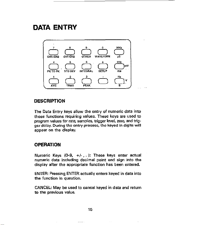
The Data Entry keys allow the entry of numeric data into
those functions requiring values. These keys are used to
program values for rate. samples, trigger kvel. zero, and trig
get delay. During the entry process, the keyed in digits will
appear on the display.
OPERATION
Numeric Keys (O-9. +/-,. I: These keys enter actual
numeric data including decimal point and sign into the
display after the appropriate function has been entered.
ENTER: Pressing ENTER actually enters keyed in data into
the function in question.
CANCEL: May be used to cancel keyed in data and return
to the previous value.
15
Page 15
Units Keys (MHz, kHz, Hzl: Determines the type of units
to be keyed in. Voltage or time or frequency units are
automatically chosen by the selected function. Pressing a
units key automatically enters the displayed data.
FRED/TIME: This key toggles the instrument between time
t@ec, msec, sl and frequency (MHz, kHz, Hz1 units. For example, sampling rate may be entered either as time interval or sampling frequency units.
Cursor Control: During the data entry process. the digit affected by pressing a numeric keey will be indicated by a
flashing segment or digit. This cursor can be moved left or
right with the downrange or uprange buttons. respectively.
PROGRAMMABLE
PARAMETERS
Perameten to be programmed with the Date Entry keys are
summarized below, along with limits and resolution of each
parameter.
16
Page 16

FUllCtkJ~
Limits
bsohJtion
RATE
SAMPLES
DELAY
LEVEL
ZERO “AL
x output
Full Scale*’
Y Output*~
Full Scale
Time Irsec-lsec
Frequency lHz-1MHz
No: l-65.535*
lime: Opsec-65,534sec’
NO Samples: -65,536 to
10’
‘lime: -65,536 to 10’sec
*20CW
*2ocw
l-1OV nominal
l-1OV nominal
RATE AND SAMPLES
PROGRAMMING
0.1 rrjec
HZ
Samples
0.1 *ec
Samples
Page 17
DESCRIPTION
A measurement is made up of a number of samples taken
at specific intervals. The number of samples in that
measurement, as well as how fast those samples are taken
can be programmed with the SAMPLES and RATE keys.
These parameters are entered with the Data Entry keeys O~CB
the mode in question is enabled.
RATE: Sampling rate may be entered in time (Isec -lpecl
or frequency (IHI-1MHr). To program sampling rate, press
the RATE key and press the numeric buttons in the desired
sequence. Press the FRECUTIME key, as required, to enter
time or frequency units.
SAMPLES: The size of the measurement may be entered
as the number of samples 11-65.536) or measurement time
duration il#ec-65,536secl. To program the number of
samples, press SAMPLES and then key in the desired value
withy the numeric keys. Use FREQiTlME to select sampling
interval or number of samples, as desired.
RECALLING DATA
Page 18

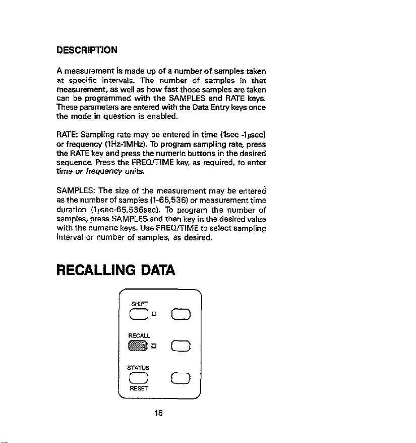
DESCRIPTION
Recall allcw you tc display individual samples within the
measurement. This mode is entered by using the RECALL
button. Once in the recall mode, individual samples may be
accessed on a sequenr,al or random basics.
OPERATION
To enter recall, simply press the RECALL button. While in
this mode, the RECALL indicator button will be on. To access individual samples, either use the uprange or
downrange keys to access individual samples, or key in a
specific sample number and press the ENTER key.
TRIGGER
DESCRIPTION
The Model 194A may be triggered in a variety of different
ways: with the TRIGGER button. with an input ~pulse ap-
plied to the TRIGGER IN jack, from the other channel, or
from the input signal. When triggering from the input signal,
the slope and trigger level can be programmed.
19
Page 19
OPERATION
SOURCE: To select the trigger scum?, press SOURCE
repeatedly until the desired mode is displayed: front panel
(TRIGGER), input signal, external. or other channel. Press
CHANNEL to save the selected source.
SGUCONI A measurement sequence can beperformed on
a continuous or single basis. In a continuous mode, the in-
strument repeatedly arms the A/D for the next trigger
measurement without requiring additional triggers. In the
single mode, B separate arm stimulus is required for each
measurement. SGLICONT toggles the instrument between
these two modes, as indicated by the respectiwindicator.
TRIGGER: When selected with the SOURCE key,pressing
this keey will initiate a continuous or single measurement,
depending on the selected mode
SLOPE: Rising or falling edge triggering may be selected with
the SLOPE key only when input signal triggering is selected.
The annunciator next to the key indicates the selected mode
LEVEL: When triggering from the input signal, the actual
voltage level et which the unit is triggered may be selected
with the LEVEL key. Once this mode is entered, the voltage
is keyed in with the Data Entry keys.
DELAY Delay selects the number of samples between the
trigger and the first sample A positive or negative delay
may be selected. Delay may be entered in number of
samples or actual time by using the FREOrrlME key.
20
Page 20

CHANNEL SELECTION
DESCRIPTION
For dualchannel units, the CHANNEL button allows you to
select one of three display modes: channel 1, channel 2,
or dual-channel display. For the two single-channel modes,
the displayed channel also determines which channel will
be affected by pressing other keys. In the dual channel
mode, most other buttons are inoperative
INPUT COUPLING
21
Page 21

DESCRIPTION
The Model 194A has three available forms of input cowl-
ing: ac, de, and ground. The selected mode of coupling is
selected with the CPLG key and indicated by the respec-
tiw indicaton. When ground coupling is selected. both ac
and dc will be off.
OPERATION
The input circuit is configured as follows for the three
modes:
DC: A straight-through dc signal path is established.
AC: Instrument response is down 3dB at 2Hz.
Ground: The high and low terminals of the input amplifier
are shorted together.
ZERO
Page 22

DESCRIPTION
Zero allows a baseline measurement to be subtracted from
subsequent measurements. The baseline can be obtained
either from an applied signal, or keyed in with the data entry keys. Once a baseline is established, it will be subtracted
from measurements until disabled. Any such zero will be
subtracted from the from the number to be displayed.
OPERATION
Zeroing an Applied Signal. Connect the signal to act as a
zero baseline with zero disabled and press the ZERO key.
Apply the measured signal and take readings es usual. The
displayed velue will be the difference between the applied
signal and the stored baseline value.
Keying in the Zero Value. To key in the baseline from the
front~panel,~press SHIFT ZERO VAL key in the desired value
then press O\lTER. The baseline will remain in effect as long
as the ZERO indicator is on.
FILTER
23
Page 23

DESCRIPTION
The Model 194A has two available low-pass analog filters
with -3dB points of 5OkHHr and 5OOkHz. These filters are
selected with the FILTER buttton. When either the 5OkHz
or SOOkHz filters are enabled, the FILTER indicator will be on.
OPERATION
To select one of the filters. simply press the FILTER button
until the correct display message is shown 60kHz SOOkHz,
or off). When the desired filter is shown, press the CHANNEL key to return to the previous mode.
24
Page 24

FRONT PANEL PROGRAMS
0 0~0.0 0
00000
DESCRIPTION
The OTHER key allows selection of a number of front panel
program modes as follows: IEEE-488 address; self test;
digital calibration: NVRAM storage; X output full scale ahe;
Y output full scale value; and Z output blanking level. These
programs are numbered O-S, and are entered by pressing
the OTHER key. Once this mode has been entered. you can
either key in the appropriate digit, or use the uprange and
downrange keys to scroll through available programs.
OPERATION
IEEE-488 Address (SHIFT, OTHER, Ok Once entered. you
can program a valid primary address (O-301 by using the
Data Entry or oursOr keys and then pressing enter.
Self Test (SHIFT. OTHERV: Performs a self test on internal
instrument circuitry and will return appropriate error
messages.
25
Page 25

Digital Calibretion (SHIFT. OTHER, 21: Digital calibration,
which requires specialized test equipment. is performed by
this program.
NVRAM Storage ISHIFT.OTHER.3): Stores calibration con-
stants in NVRAM once the unit is calibrated.
X Output Full Scale (SHIFT.OTHER,4): Programs the maximun voltage at the X analog output jack.
Y Output Full Scale (SHIFT. OTHER, 51: Sets the maximum
voltage of the Y analog 0utpuL
2 Output Blanking Level (SHIFT. OTHER.6): Determines the
blanking level at the 2 analog output.
SETUP
ooo@o
I’
DESCRIPTION
Setup allows you to store up to two different instrument
configurations in NVRAM. These setups can then be later
26
Page 26

recalled. thus simplifying instrument configuration for a
variety of different test procedures.
OPERATION
Saving Setups: Select the channel !or scanner) to be configured and program the desired modes. Press the SETUP
button twice followed by the desired setup number W2).
Press ENTER to store the selected configuration. Setup 0
contains the fectoly defaults and Cannot be reprogrammed.
Recalling Setups: Press SETUP followed by the desire setup
number. Press the ENTER key to recall the desired setup
STATUS
DESCRIPTION
The current instrument status for both channels. ten be
determined by recalling instrument status with STATUS key.
27
Page 27

The returned status velues will depend on the jxesent
selected operating modes.
OPERATION
To access instrument status, simply press the STATUS key
once, the unit will display the following stetos parameters
in the following order, moving through the list et about one
item per second:
Zero value
Filter status (50kHz or SOOkHzj
Trigger *cum*
Wgger mode
Trigger delay
migger level
Sample rate
Measurement size
Maximum semple rate for each resolution
RESET
DESCRIPTION
The RESET key allows wu to quickly return the instrument
to the power-on default configuration (setup 1). Both A/D
channels will be effected by this key.
OPERATION
lb simulate a power on reset, simply press SHIFT RESET.
28
Page 28

XY MODE
DESCRIPTION
The XY mode allows you to plot your data on a display
device such es a CRT, o*cilloscope, or plotter. Connections
to these plotting devices is made through* the X, Y, end
2 analog output jsck on the rear panel. Various scaling factom cm be applied to the data before being plotted.
OPERATION
XY MODE: Enters the XY mode and ellows the *election
of the type of plotting device: CRT, oscilloxopa or plotter.
XY DATA: Allows you to select the source of data to be
displayed. individual samples from the measurement buffer, or readings from the display buffer for either channel
1 or channel 2.
XY TRIG: Used to *tart and stop the analog output
sequence.
29
Page 29

XY ZOOM: Provides a methad of scaling data located in the
buffer to the display window.
XY PAN: Controls which data point is the first displayed
in the window.
30
Page 30

INPUT AND OUTPUT
CONNECTIONS
A/D MODULE INPUT/OUTPUT
CONNECTIONS
DESCRIPTION
Each A/D module has several input D, output connectors
on the rear panel for voltage signal input, real time output,
and trigger input and output. Each of these connectors is
briefly described below.
OPERATION
VOLTAGE INPUT: All voltage input signals are applied to this
SNC jack for processing and AID conversion. Note that the
maximum input voltage is 25OVps~ak, 2 x 10,‘V Hz. The
maximum cmnmon mode voltage is 30%
REAL TIME OUTPUT A/D data at the sampling rate may
be read via this output. Data can be transmitted in S-bit
or %-bit format This connector is also used to select between internal and external sample rate clocks.
TRIGGER IN: A negative*oing pulse at TTL levels llO$c+ec
minimum) can be applied to this jack to one trigger a
measurement. External triggering must be selected with the
SOURCE key before this connector is active
31
Page 31

TRIGGER OUT A negative going lO#sec pulee et TTL levels
will appear et this jack when a valid meaeurement trigger
occurs. The pulse will occur regardless of the selected trig-
ANALOG OUTPUT
CONNECTIONS
DESCRlPTlON
The analog output includes three jacks located on the rear
panel. labeled X, Y, and 2. Signals appearing at these jacks
are controlled by the XY mode. Each jack is a standard BNC
m”“eCtOL
X OUTPUTr This signal, which provides time information,
should be used as en X-axis signal for a plotter or CRT.
Y OUTPUT The Y output provides amplitude about the
verlo~s samples, and should be used as a Y-axis signal for
the CRT and plotter, and vertical input information for an
oscilloscope.
Z OUTPUT: The Z output provides a blanking pulse for a
CRT. en external triggerpulse for an oeoillosoope, of a pen
up signal for e plotter.
32
Page 32

EXTERNAL CLOCK
DESCRIPTION
The external clock jacks provide methods of synchronir-
ing two or more Model 194s together to a common time
base. as described below.
OPERATION
CLK IN: An externally generated 1OMHz clock et TTL levels
can be applied to this input to synchronize sample taking
to an external time base. Detection and switching is
a”tOmatic
CLK OUT: Normally. the internal 1OMHz clock (TTL levels1
of the Model lg4A will appear et this output. If the unit
Is operating with en external time base, the external clock
rate will appear et CLK OUT instead.
Synchronizing units: To synchronize units, connect the CLK
OUT of the master unit to the CLK in of the dave unit. Other
unite may be daisy chained in a similer manner.
33
Page 33

IEEE-488 PROGRAMMING
DEVICE-DEPENDENT COMMANDS
FUNCTION
FO
Fl
F2
F3
F4
FS
FS
F7
F20
F21
Waveform bmple at trigger
point)
Average
TRMS
+ Peak
- Peek
Peak-to-oeak
Standard deviation
Integral
CHI-CHZ
CHlICH2
Auto
320mV
3.2V
32v
2oov
Cancel auto lst*y on present
range)
Page 34

TRIGGER
TO
n
T2
T3
T4
T5
T6
T7
T20.m
T21.m
T22.m
T23.m
124
T26
T26
T27
T30
T31
Continuous, talk
Single, talk
Continuous. GET
Single, GET
Continuous, X
Single, X
Continuous, external
Single, external
Continuous, + slope. level m
i-ZOOrmr+2OOV)
Single, + slope, level m
(-200~ms+200Vl
Continuous, - slope, level m
(-200sm~+200Vl
Single, - *lope, level m
I-200~m~+ZOOV)
Continuous, other channel
Single, other channel
Continuous, immediate
Single, immediate
Start plotter
Stop plotter
36
Page 35

De& in set ~-65.536~m_clE71
‘. ,,I, .,,, 2 ‘i,
( DATA FORMAT
GO
Gl
G2
G3
G4
ii:
G7
I
~,,. ,“...Y.. .,.,., :~ :~ ,~,,. ,,
‘ASCII; 1 rdg. prefix on, suffix off
ASCII. 1 rdg, prefix off, suffix off
ASCII, 1 rdg, prefix an. suffix on
*SC11. n rdgs. prefix on. suffix off
ASCII. n rdgs. prefix 0% suffix ofl
ASCII, n rdgs. prefix oh suffix on
Binary, n rdgs. prefix off, suffir
Off
Binary, n rdgs Ibyte countI. p~refix
off. suffix off
37
Page 36

02.2
02.3
02.4
02.5
03.0
03.1
03.2
03;3
04.m
05.m
06.m
07.m
06.m
09
scope mode
Future expansion
Slow plot (XY analog plotters
Strip chart
Measurement buffer
64k RAM buffer
Display readings
IEEE-488 reading ~buffer
m-X output full *tale voltage
(1 smsl0)
m=Y output full scale voltage
(1 smrlo)
m=Z output blanking level
U=high, O=loW
m=XY zoom Yal”e
(0.1 rmslooo)
m=XY pan value
I-65.536ams65.5361
start plotter
B3.m
I
pointer to m.
Set reading buffer start pointer to
tn.
36
I
Page 37

READING BUFFER
QO
Ql
Q2
flLTEi7
PO
F
F1
F2
Reading buffer off.
Linear reading buffer on.
Circular reading buffer on.~
Filter off
500kHz filter
50kHz filter
Z3.m
24
Z5.m
INPUT COUPLING
IO
I1
12
Use value m as baseline value
(-200~ms+200V)
22 + Zl
23 +~Zl (-ZOOsms+ZOOVI
DC coupling
AC coupling
Ground coupling
39
Page 38

STATUS
uo
Ul
u2
u3
u4
u5
U6
U8
us
UlO
Ull
u12
Error status
Data *muus
Zero IZ) parameter
Delay (WI parameter
Number samples (NI parameter
Sample rate 61 parameter
Trigger levsl
Measurement buffer start pointer
Measurement buffer end pointer
Reading buffer start pointer
Get Translator list
M32
Error
40
Page 39

TERMINATOR
Ylll
Yn,m
Y (DELI
RECALL
A0
Al
A2
Program m as single terminator
Program mn as dual terminator
No terminator
Recall factory setup
Recall setup 1
Recall setup 2
41
Page 40

HIT SUTTDN
Hi7 Act as if button n (l-381 has been
DISPLAY
DaaaaX
DX
SELF TEST
Jl Ul self test byte =1: fail
EXECUTE
X Execute other devicedependent
pressed
Display ASCII characters aaaa 114
maximum)
Return to normal display mode
commands
42
Page 41

Figure 1. SRQ Mask and Status Byte Format
Figure 2. ASCII Data Format (GO to G5)
43
Page 42

Page 43

45
Figure 3. Binary Data Format (Cont.)
Page 44

FUNCTION (FM)
OO=WAVEFORM
Ol=AVERAGE*
OZ=TRMS
03=+PEAK
04=-PEAK
06=PEAK TO PEAK
06=STANDARD DEVlATlON
07=INTEGRAL
20=CHl-CH2
21=CHl/CH2
RANGE (Ann)
O=AUTO’
1=32OmV
2=3.2V
3=32V
4=2OOV
TRIGGER (mn)
OO=CONTINUOUS, TALK
Ol=SINGLE. TALK
OZ=CONTINUOUS, GET
03=SINGLE, GET
04=CONTINUOUS, X
05=SINGLE, X
OB=CONTINUOUS, EXTERNAL
07=SINGLE, EXTERNAL
ZO=CONTINUOUS, +SLOPE
21=SINGLE, +SLDPE
Figure 4. UO Status Word Format
46
Page 45

22=CONTINUOUS, -SLOPE
23=SINGLE, -SLOPE
24=CONTINUOUS, OTHER CHANNEL
25=SINGLE, OTHER CHANNEL
26=CONTINUOUS,~ IMMEDIATE*
27=SlNGLE, IMMEDIATE
3O=START PLOTTING
31=STOP PLOTTING
FILTER (Pn)
O=OFF’
1=600kHr
2=50kHz
ZERO (Zn)
O=DISABLED*
1 =ENABLED
2=SAVE MEAS
S=USE VAL.
4=Zl + 22
5=Zl f-Z3
EOI, BUS HOLD OFF (Kn)
O=EOI, HOLD OFF’
l=NO EOI, HOLD OFFS
2=EOI, NO HOLD OFF
3=NO EOI, NO HOLD OFF
BUTTON PRESSED (Hnn)
OO=NONE
01 =ZERO
OZ=FILTER
03=TRIGGER
04=SGL/CONT
05=SOURCE
06=DELAY
Figure 4. UO Status Word Format (Cont.)
47
Page 46

07=SLOPE
OII=LEVEL
09=SCAN
lO=CPLG
ll=SAMPLES
lZ=RATE
13=LOCAL
14=CHANNEL
15=AUTO
16=%
l7=.,
18=SHIFT
lS=RECALL
2O=sTATUS
Zl=ENTER
ZZ=CANCEL
ZB=FREQ/TIME
24=7
25=4
26=1
27=8
28=5
29=2
3O=S
31=6
32=3
33=6
34=*
35=*
36=MHz
37=kHr
38~Hr
Figure 4. UO Status Word Format (Cont.)
48
Page 47

INPUT COUPLING (In)
O=DC COUPLING’
,=AC COUPLING
Z=GROUND COUPLING
RECALL SETUP (A”)
O=FACTORY SETUP’
l=SETUP 1’
Z=SETUP~ 2
SAVE (Ln)
l=SAVE SETUP I*
2=SAVE SETUP 2
4=CALlBRATE USING VALUE
5=STORE CAL IN NVRAM
READING BUFFER (Qn)
O=DISABLED*
l=LINEAR BUFFER
2=CIRCULAR BUFFER, OVERWRITE
DATA FORM&T IGn,
O=ASCII. PREFIX ON, SUFFIX OFF, ,RDG
l=ASCII, PREFIX OFF, SUFFlX OFF, ,RDG
2=ASCII, PREFIX ON, SUFFlX ON, IRDG’
3=ASCIL PREFIX ON. SUFFIX OFF. n RDGS
4=ASCII. PREFIX OFF, SUFFIX OF+, n RDGS
5=ASCII. PREFIX ON, SUFFIX ON, n RDGS
B=BINARY, PREFIX OFF, SUFFIX OFF
7=8INARY, PREFIX OFF, SUFFIX 0FF;BYTE COUNT
SELF TEST (Jnn)
CODE/MEANING
OO=NO ERROR
Ol=SELFTEST COMPLETE, NO ERROR
(GOES TO 00 IJO READ]
Flgure 4. UO Status Word Format (Cont.)
49
Page 48

02=NOT USED
03=NOT USED
04=NOT USED
05=NOT YSED
06=NOT USED
07=NOT USED
OB=RAM ERROR ON MOTHERBOARD
09=ROM ERROR ON MOTHERBOARD
lX=A/D ERROR ON CHl
(SEE TABLE BELOW FOR X MEANING)
2X=A/D ERROR ON CH2
ISEE TABLE BELOW FOR X MEANING)
A/D ERROR CODES
O=NOISY AID
l=NOT USED
2=INOPERATIVE CAL
3=NOT USED
4=NOT USED
5=TIMEBASE ERROR
fi=NOT USED
7=RAM ERROR
CHANNEL (Cm)
Ol=CHANNEL I*
02=CHANNEL 2
12=COMPOSiTE CHANNEL
SRQ (Mnnn)
OOO=DlSABLED’
OOl=OVERFLOW
002=DATA
004=HIT BUTTON
OOB=READING DONE
O,S=~READY
032=ERROR
ADJUSTMENT
Figure 4. UO Status Word Format (Cont.)
50
Page 49

TERMINATOR (Ynnnnnn)
nnnnnn=YlASCII)
000000=No TERMINATOR
O,SOlO=CR LF*
TERMINATOR
DEFAULT CR LF
Figure 4. UO Status Word Format (Cont.)
Page 50

BUTTON NUMBERS USED BY HIT COMMAND
AND RETURNED IN UO STATUS
0 NOW
1 ZERO 22
2 Flu-m
3 TRIGGER
: SGL/CONT SOURCE
6 DELAY
7 SLOP&
8 EE
9
10 CPLG
11 SAMPLES
12 RAT?2
I3 LOCAL
14 ChxNNEL
I5 Au-r0 E
16 uP=JW
I7 DOwnrange
18 SHFl
RECALL
I9
20 STATUS
21
28
24
25 26
27
28
29
80
31
32
33
84
37
38
52
Page 51

53
Figure 5. Ul Status Word Format
Page 52

54
Page 53

Figure 7. U3-Ull Status Word Formats
55
Page 54

TRANSLATOR MODE
DESCRIPTION
The Translator mode allows you to substitute English-like
words in place of device-dependent commands or commands strings. For example the word SAMPLES could take
the place of the command NlOOOX, which programs the
instrument to take 1000 samples. A single word can also
replace a group of commands at one time For example. the
word SETUP1 could be used to replace the following cornmand string: FlS+lOON250W+-25Z1P2X.
RESERVED WORDS AND SYMBOL
Tmnslator resewed words and symbol are listed~below, along
with a brief description of each word.
Reserved Word Description
ALIAS
NEW
OLD
LIST
FORGET
Define Translator words. enable
Translator.
Enable Translator, combine words.
Disable Translator.
Get list of Tmnslator words from
instrument.
Purge Translator words.
Terminate Translator command
string.
56
Page 55

EXAMPLES
“ALIAS SETUP1 ROFlX ;* - Defines the word SETUP! in
place of ROFlX.
“ALIAS TE’34 N1000S+1010X ;* - Defines TEST4 in place
of N1000S+1010X.
57
Page 56

CONTROLLER PROGRAMS
The following programs have been supplied as a simple aid
to demonstrate basic programming techniques and are not
intended to suit specific needs. Each program allows you
send a device-dependent command string to the instrument
and obtain Andy display an instrument reading string. The
returned data is an ASCII string variable of the form:
NAVG+1.2345 CR LF
Here, CR LF represents the default carriage return, line feed
terminator and will not normally be displayed.
A note included with each program indicates modifications
necessary to provide a numeric variable of the form:
11.2345
Programs for the following contmllers are included:
IBM PC or Xl (with CEC IEEE-488 interface).
Hewlett-Packard 300 series computer running BASIC,
58
Page 57

IBM XT or PC (with CEC Interface)
Page 58

HEWLETFPACKARD SERIES 300
The following program sends a command string to the
Model 194A from a Hewlett-Packard Model 310 computer
and displays the instrumsnf reading string on the computer
CRT. The computer must be equipped with the HP82937
GPIB Interface and HP BASIC 4.0
DIRECTIONS
1. Using the front panel program feature, set the primary
address of the Model 194A to 9.
2. With the power off. connect the Model 194A to the
~HP82937A GPIB interface installed in the 9816 computer.
3. Type EDIT and press the EXEC key.
4. Enter the lines in the program below, using the ENTER
key after each line
6. Press the 9816 RUN key and type in the desired command string at the command prompt. For example, to
place the instrument in the autorange and average modes,
type in ROFIX and press the ENTER key.
6. The instrument reading string will then appear on the
CRT. A typical display is: DAVG+1.2345.
60
Page 59

PROGRAM COMMENTS
IBRE”OTE789 Place 194A in remote
20 INPUT“ COFiMClND Prompt for and input command.
STRING”;A*
30 OUTPU*09;** Address 194A to listen, send
40 ENTER 709; BB Address 194A to talk, input
string.
readina.
Display reading string.
Repeat.
Page 60

ASCII Character Codes and
IEEE-488 Multiline Interface
Command Messaaes
Decimal Hexadecimal ASCII I
0 00 NUL
1 01 SOH GTL
2 02 8Tx
3 03
4 04
6 05
ETX
EOT
ENQ
SDC
PPC
; 06 07
8 08
9 09
10 OA
11 08
12 oc FF13 OD CR
14 OE so
15 OF SI
16 10 DLE
17 DC1
24 18 CAN
26 19
26 IA
28 1c
27 18
29 ID GS
30 lE RS
ACK 8EL
8S
HT
LF
VT
Z
GET
TCT
LLO
DCL
PPU
SPE
SPD
Page 61

hAmal Hexadecimal ASCII IEEE-488 Message’
32 20 ASP MLAO
33 21 I MLAl
34 22 ” MLA 2
ii ii
39 ~27
40 28
41 29
42 2A
43 43 26 26
44 44 2c 2c
46 46 2D 2D
46 46
47 47 2F 2F
48 48 30 30
49 49 31 31
50 50 32 32
z: z:
53 53 35 35
54 54 36 36
66 66
56 56
57 57 39 39
58 58 3A 3A
59 59 38 38
60
61
62 3E > MLA 30
63
2E 2E
33 33
34 34
,“;: ,“;:
;;
3F
# MIA3
?i MLA MLA 4 5
& MLA 6
i
1 MLA 9
’ _ MLA10
+ MIA 11
i MLA MLA 14 15
0 MLA16
1 MLA 17
2 MLA 18
3 MLAIS
4 MLA 20
5 MLA 21
6 MLA 22
~7 MLA 23
8 MLA 24
9 MLA 26
;
= MLA 29
? UNL
MLA7
MLA 8
MLA 12
MLA 13
MLA 26
MLA 27
MLA 28
Page 62

Decimal Hexadecimal ASCII IEEE-468 Message*
64 40 f MTA 0
65 41 MTA 1
66 42 B MTA 2
67 43 C MTA 3
68
69 45
70 46
71 47
74 4A
75 48
76 4c
77 4D
78 4E
2
81
62 52
63
84 64
87 57
88 5*
44
48
49
4F
~~ 50
51
53
D MTA 4
E MTA 5
F MTA 6
ii MTA MTA 7 8
I MTA 9
J MTA 10
K MTA 11
L MTA 12
M MTA 13
N MTA 14
0 MTA 15
P MTA 16
Q MTA 17
R MTA 18
S MTA 19
T MTA 20
U MTA 21
V MTA 22
W MTA 23
X MTA 24
Y MTA 25
2 MTA 26
i MTA MTA MTA 28 29 27
A MTA 30
UNT 95 5F
Page 63

leclmal Hexadecimal ASCII IEEE-488 Message’
96 60
97 61
98 62
99 63
100 64
101 65
102 68
103 67
104 68
105 69
106
107 66 :
108 6C I
109 6D m
110 6E n MSA 14,PPE
111
112
113
114
115
116
117
118
119
120
12,
122
123
124
125
126
127
ETA
6F
70
71
72
::
76
76
:;
79
7A
76
7c
7D
7E
7F DEL
MSA O.PPE
MSA 1,PPE
MSA 2,PPE
MSA 3,PPE
MSA 4,PPE
MSA 5,PPE
MSA 6,PPE
MSA 7,PPE
MSA 8,PPE
MSA 9.PPE
MSA 10,PPE
MSA ll,PPE
MSA 12,PPE
MSA 13,PPE
MSA 15;PPE
MSA 16,PPD
MSA 17,PPD
MSA ILPPD
MSA 19,PPD
MSA 20,PPD
MSA 21,PPD
MSA 22,PPD
MSA 23,PPD
MSA 24,PPD
MSA 25,PPD
MSA 26,PPD
MSA 27,PPD
MSA 28,PPD
MSA 29,PPD
MSA 30,PPD
 Loading...