

Keating Of Chicago Hands Free User Manual
A. FILTER-DRAWER
WARNING!
WATER + HOT OIL = DON'T MIX!
1. Operator should be outfitted with proper protective
attire: safety goggles, oil and heat resistant gloves,
apron and footwear
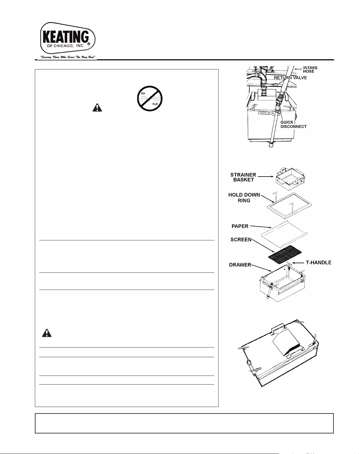
2. Release intake hose from filter drawer using the quick
disconnect. Refer to Figure 1.
3. Pull filter drawer forward and remove the cover and
strainer basket. Refer to Figure 2.
4. Release the spring loaded T-Arms located in the corners
of the filter drawer and remove the hold down ring. Refer
to Figure 2.
5. Filter screen should be in bottom of drawer. Place filter
paper on top of screen.
6. Position hold down ring on top of paper and secure with
T-Arms. Refer to Figure 3.
NOTE: Hold down ring makes a gasket-like seal on filter
paper. Filter paper must be placed edge to edge from front to
back, overlapping on sides. Filter Paper must be smooth and
flat under hold down ring to get a proper seal.
NOTE: One package of Acidox is needed for every 40 pounds
of oil.
7. Sprinkle Keating Acidox Powder evenly over the paper.
8. Replace strainer basket and cover, push drawer fully into
cabinet and reconnect intake hose and pull up on hose to
check connection.
CAUTION
Pull up on hose to check connection.
NOTE: Cabinet door should be closed during filtration.
NOTE: For best results, new filter paper and Acidox Powder
should be used for each fryer.
B. PREPARING OIL FOR FILTRATION
NOTE: Oil in fryer must be between 250° - 350°F.
1. Turn fryer completely off.
FIGURE 2. FILTER DRAWER ASSEMBLY
FIGURE 3. FILTER DRAWER COMPLETE WITH
SCREEN, FILTER PAPER, HOLD DOWN RING,
ACIDOX, STRAINER BASKET AND COVER.
HANDS FREE CENTRAL FILTER
OPERATING INSTRUCTIONS
KEEP THIS MANUAL FOR TRAINING NEW PERSONNEL
FIGURE 1. QUICK DISCONNECT
– 1 –
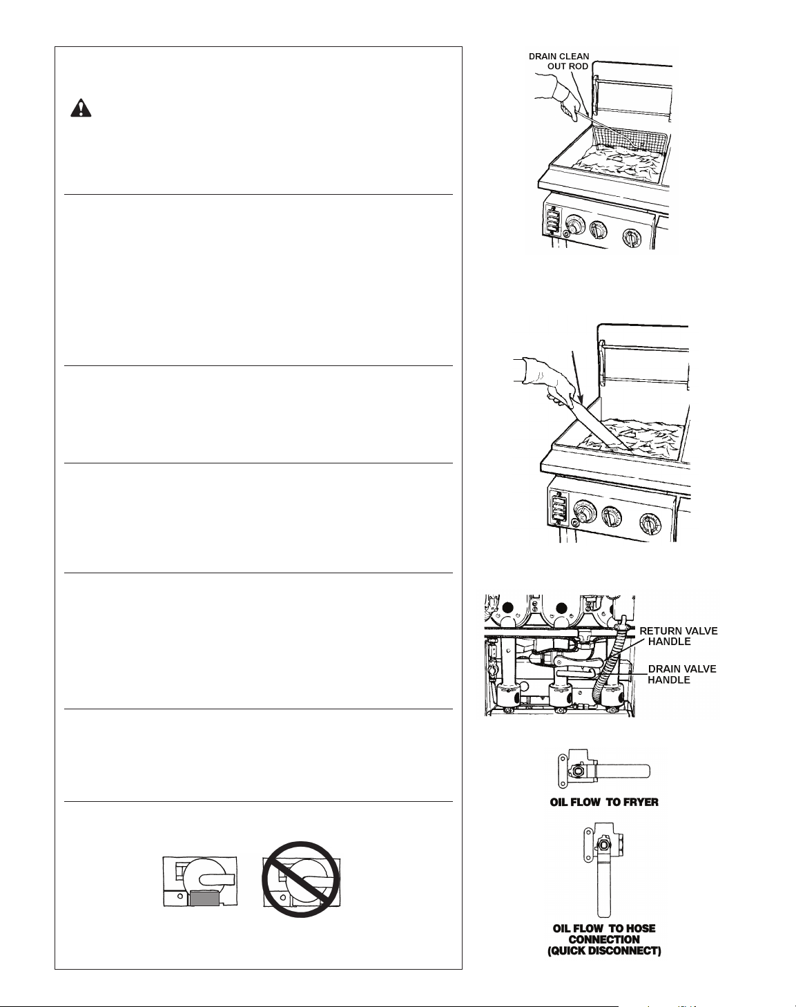
2. Remove screen from over tubes/element with tongs or a
Drain Clean Out Rod. Refer to Figure 4.
CAUTION
Screen over tubes will be very hot and should be moved
to a safe place.
3. Use spoon provided to stir oil. Bubbling will occur until all
water is removed. Refer to Figure 5.
NOTE: Water settles in the cooler oil in the Cold Zone. If the
water is not removed, the filter paper absorbs the water
preventing the oil from passing through it.
C. FILTRATION
1. In fryer cabinet, have return valve handle located directly
above the drain valve set to oil flow to fryer. Refer to
Figure 6.
2. Open the drain valve by lifting and then pulling the drain
valve handle and drain fryer.
NOTE: A Drain Clean Out Rod may be needed to loosen any
solid residue. Use it only when valve is fully open.
3. Wipe crumbs from splashdeck while fryer is empty.
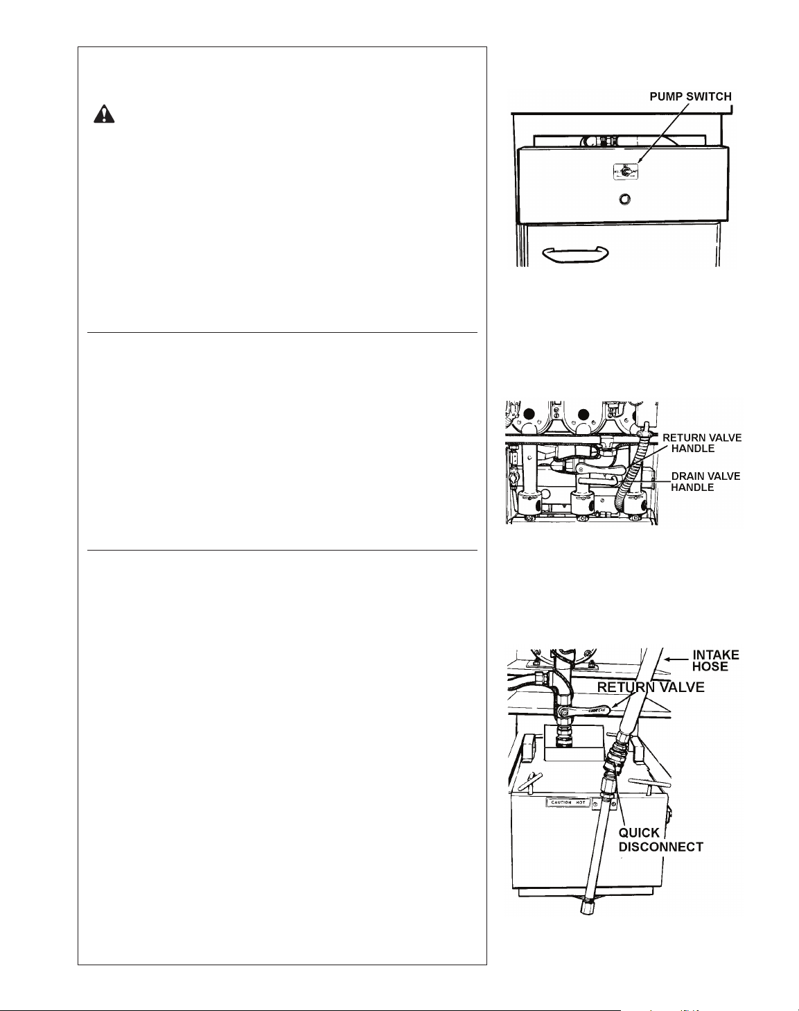
4. On the filter panel, turn the pump switch to the “Pump” or
“ON” position. Refer to Figure 8.
NOTE: If oil does not return to fryer, set pump switch to
“MELT” position for ten minutes to melt any solidified
shortening in the return pipe (only on models with melt cycle.)
5. Let the pump run with drain valve open to remove crumbs
and residue from the bottom of fryer and the drain lines.
Failure to do so may cause the drain lines to clog up.
NOTE: If the pump shuts down, turn it off and let the motor
cool.Then pull motor reset lever located in filter cabinet.
Check filtering procedure or clean pump if needed.
6. Partially close drain valve to allow fryer to fill above
tubes/elements.
7. Let swirling action rinse down fryer.
8. Fully drain fryer.
NOTE: Pump should be run for at least 30 seconds after
crumbs are removed from fryer. This will help prevent
blockage in the drain lines.
9. Close drain valve and completely refill fryer. Refer to
Figure 9.
NOTE: The drain valve handle activates fryer’s Main Power
Switch. If drain valve is not fully closed and locked, fryer will
not operate.
10. Turn pump switch to the “OFF” position and close return
valve.
FIGURE 4. REMOVE SCREEN OVER
TUBES/ELEMENTS
FIGURE 5. STIR WITH SPOON PROVIDED
TO REMOVE WATER
FIGURE 6. FRYER VALVE HANDLES
FIGURE 7
FIGURE 9
– 2 –
SPOON
D. CLEAN UP
CAUTION: Filter drawer and pipes will remain hot
following filtration. Allow the unit to cool down before
clean up. Failure to do so may result in serious injury to
the operator.
1. Release intake hose from filter drawer using the quick
disconnect. Refer to Figure 10.
2. Pull filter drawer forward and remove the cover and
strainer basket. Refer to Figure 2.
3. Release the spring loaded T-Arms located in the corners
of the filter drawer and remove the hold down ring. Refer
to Figure 2.
4. Thoroughly clean and dry the filter drawer.
NOTE: Tilt the drawer towards the back to fully drain sump.
This will prevent solidified oil from blocking the pipe.
5. Replace filter screen after cleaning.
6. Place filter paper on top of screen.
7. Position hold down ring on top of paper and secure with TArms. Refer to Figure 3.
8. Sprinkle Keating Acidox powder over the paper.
9. Replace strainer basket and cover, push drawer fully into
cabinet and reconnect intake hose. Check to ensure
proper connection.
10. Close the cabinet door.
NOTE: Instructions for cleaning the fryer are in the Operating
Section of the fryer Service Manual.
E. CLEANING AND BOIL-OUT
When cleaning and boiling out your fryer use Keating Sea
Powder and Keating Klenzer to keep your fryer in top
condition.
Operator should be outfitted with proper protective attire:
- safety goggles
- oil and heat resistant gloves, apron and footwear
Turn the fryer off.
A cleaning hose and wand have been provided for cleaning
the fryer and discarding the oil.
Attach cleaning hose to quick disconnect located below the
valve handle in filter cabinet.
Remove fry baskets and screen. Drain fryer into the central
filter drawer.
Set the return valve to “oil flow to hose.” See Figure 6 & 7.
The hose may now be used to rinse the tubes/elements and
fry pot and to pump the oil into the shortening handling
system and discard properly.
FIGURE 8. FILTER CONTROL PANEL
FIGURE 9. DRAIN VALVE HANDLE
FIGURE 10. QUICK DISCONNECT
– 3 –
 Loading...