

Page 1
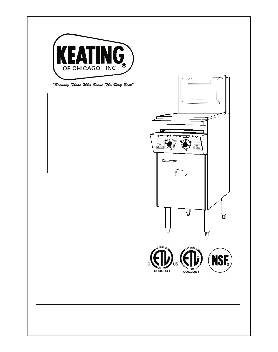
KEEP THIS MANUAL FOR TRAINING NEW PERSONNEL
1-800-KEATING
www.keatingofchicago.com
Part # 000000 Electric Pasta 0107 09/07
CUSTOM
PASTA
™
SYSTEM
ELECTRIC
SERVICE
MANUAL
Page 2
i
This operating, installation, and service manual should be given to
the user. The operator of the Custom Pasta
™
System should be
familiar with the functions and operation of the cooker. This manual
must be kept in a prominent, easily reachable location near the Pasta
System.
POST THIS LABEL IN A
PROM INENT LOCATION ON
YOUR UNIT
Using any parts other than genuine, Keating of Chicago, Inc. factory
manufactured part relieves the manufacturer of all warrant and liability.
Keating of Chicago, Inc. (manufacturer reserves the right to change
specifications at any time.
IMPROPER INSTALLATION, ADJUSTMENT,
ALTERATION, SERVICE OR MAINTENANCE
CAN CAUSE PROPERTY DAMAGE, INJURY OR
DEATH. READ THE INSTALLATION, OPERATING
AND MAINTENANCE INSTRUCTIONS
THOROUGHLY BEFORE INSTALLING OR
SERVICING THIS EQUIPMENT.
FOR YOUR SAFETY
DO NOT STORE OR USE GASOLINE OR
OTHER FLAMMABLE VAPORS AND LIQUIDS
IN THE VICINITY OF THIS OR ANY OTHER
APPLIANCE.
WARNING
Do not store flammable
liquids near this or any
other appliance.
WARNING
Improper installation
can cause damage,
injury or death.
Page 3

SECTION I SPECIFICATIONS . . . . . . . . . . . . . . 1
SECTION II INSTALLATION
Shipment and Transit . . . . . . . . . . . . . . . . . . . . . . . .1
Installation . . . . . . . . . . . . . . . . . . . . . . . . . . . . . . . .1
A. Placement . . . . . . . . . . . . . . . . . . . . . . . . . . . . .1
B. Electrical Connection . . . . . . . . . . . . . . . . . . . . .1
C. Water & Drain Connection . . . . . . . . . . . . . . . . .1
SECTION III OPERATION
Thermostats . . . . . . . . . . . . . . . . . . . . . . . . . . . . . . .2
Control Features . . . . . . . . . . . . . . . . . . . . . . . . . . .2
The Auto-Fill System . . . . . . . . . . . . . . . . . . . . . . . .2
Drain . . . . . . . . . . . . . . . . . . . . . . . . . . . . . . . . . . . .3
Electronic Timer . . . . . . . . . . . . . . . . . . . . . . . . . . . .3
SECTION IV MAINTENANCE
Preventive Maintenance . . . . . . . . . . . . . . . . . . . . .4
Cleaning . . . . . . . . . . . . . . . . . . . . . . . . . . . . . . . . . .4
Calibration . . . . . . . . . . . . . . . . . . . . . . . . . . . . . . . .4
A. Tools . . . . . . . . . . . . . . . . . . . . . . . . . . . . . . . . . .4
B. Calibration . . . . . . . . . . . . . . . . . . . . . . . . . . . . .4
SECTION V SERVICE AND PARTS INFORMATION
Auto-Fill System . . . . . . . . . . . . . . . . . . . . . . . . . .4-5
Cooker Heating Section . . . . . . . . . . . . . . . . . . . . . .5
Ordering Parts . . . . . . . . . . . . . . . . . . . . . . . . . . . . .5
SECTION VI SERVICE DIAGNOSIS
Troubleshooting . . . . . . . . . . . . . . . . . . . . . . . . . .6-8
SECTION VII PARTS LIST
Control Panel Assembly . . . . . . . . . . . . . . . . . . . . .9
14” Drop-In Custom Pasta Parts List . . . . . . . . . . .10
18” Custom Pasta Parts List . . . . . . . . . . . . . . . . .10
SECTION VIII WIRING DIAGRAMS
14" Electric Pasta, 2-Thermostat without timers . .11
14" Electric Pasta with 138 timers . . . . . . . . . . . . .12
18" & 20" Electric Pasta with 138 timers . . . . . . . .13
18" Electric Pasta, 2-Thermostats without timers .14
WARRANTY
Keating Warranty . . . . . . . . . . . . . . . . . . . . . . . . . .15
TABLE OF CONTENTS
1
Page 4
2
I INTRODUCTION
GENERAL
Keating Electric Custom Pasta™Systems are designed
to give maximum production efficiency, delivering high
quality food products. The following design features are
incorporated in Keating Pasta Electric Systems.
STANDARD FEATURES
• Highly polished stainless steel vessel
• Highly polished stainless steel front
• Highly polished stainless steel elements
• Highly polished stainless steel thermostat bulb
• Highly polished stainless steel Hi-Limit sensor
• Grid screen over elements
• Automatic water fill with manual override
• Water solenoid and indicating light
• Starch overflow
• Two electronic timers
• Low water safety shutoff
• 1" full port front drain valve on 14;
1
1
/4" for 18 and larger
• High temperature limit control with manual reset
• Patented accurate temperature control system
±2°F
• Ideal 35" working height
• One pair of split baskets or one perforated basket
• Patented dual thermostat system
• Indicating lights for pilot and secondary thermostat
on
STANDARD ACCESSORIES
• Keating Klenzer Sample
• Keating Sea Powder Sample
• Drain clean out rod
• Sensor Cleaning Brush
STANDARD PASTA SYSTEMS
• Sizes: 14 to 24
• Water capacity 51/
2 to 17
1
/
2 gallons
• 24 Pasta System can cook 6 lbs. of dry pasta per
load up to 110 lbs. per hour
• NSF certified
• ETL Certified listed
• ETL Sanitation Certified listed
MODEL VARIATIONS
Basket-Lift Model: Basket-Lift Model Pasta Systems
come with all the same features as the standard
models. The Basket-Lift mechanism lowers the baskets
of food into the water when the timer button is pressed
and raises the baskets when the cooking cycle is
complete. Split baskets are required for these models.
SPECIFICATIONS
SAFETY
PRECAUTIONS
THIS SYMBOL WARNS YOU THAT SERIOUS BURNS
OR OTHER INJURIES MAY RESULT IF SAFETY
INSTRUCTIONS ARE NOT FOLLOWED.
• This service manual should be retained in a safe
place for future reference. The installation of your
new Pasta System must conform to local codes
and with the current National Electrical Codes and
regulations as applicable.
• Your ventilation hood, when installed, must conform
to the current standards.
• No frame or restriction shall be constructed around
the Custom Pasta System that will restrict air
movement into the Pasta System or prevent proper
ventilation.
• You must maintain this appliance free and clear
from combustibles.
• Adequate clearance for servicing and proper
operation must be maintained. Your pasta system
is designed to be serviced from the front.
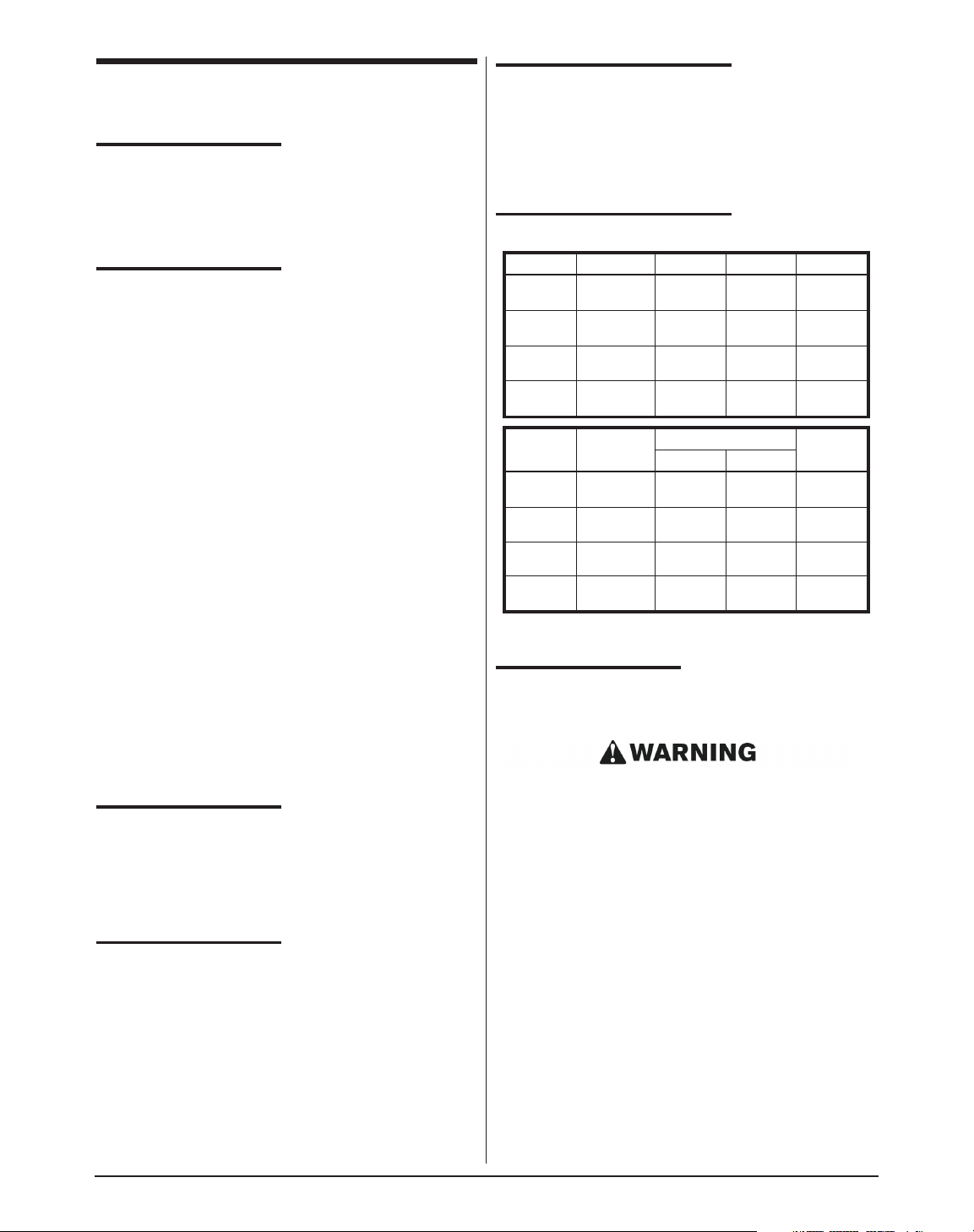
MODEL kW @ 240V
AMPS
SHIP WT.
3P 1P
14 15.5 32-56-32 65 125 lbs
18 20.7 50-50-50 87 175 lbs.
20 20.7 50-50-50 87 200 lbs.
24 28.6 52-82-82 119 300 lbs.
MODEL CAPACITY HEIGHT DEPTH WIDTH
14 7 gal. 461/2" 311/8" 153/8"
18 10 gal. 461/2" 331/8" 193/8"
20 15 gal. 461/2" 351/8" 213/8"
24 19 gal. 461/2" 391/8" 253/8"
Page 5
• Keating Custom Pasta™Systems are intended for
other than household use.
• ALWAYS instruct new employees on proper pasta
system operation.
• A Custom Pasta System™should be operated
ONLY by properly trained personnel.
• ALWAYS turn pasta system off each night.
• ALWAYS turn pasta system off at customer power
panel before servicing.
• NEVER leave a pasta system unattended during
operation.
• NEVER move a pasta system when full of hot
water.
• NEVER introduce objects or liquids into pasta
system, while operational, which are not designed
or made for cooking.
• THIS CUSTOM PASTA
™
SYSTEM MAY NOT BE
ALTERED, MODIFIED OR CHANGED IN ANY
WAY.
IF THE EQUIPMENT IS NOT
INSTALLED, OPERATED AND
MAINTAINED IN ACCORDANCE
WITH THE ABOVE,
CONCENTRATIONS OF CARBON
MONOXIDE IN EXCESS OF THE
ESTABLISHED LIMITS COULD BE
PRESENT IN THE KITCHEN
ENVIRONMENT.
ALL PERSONNEL IN THE WORK PLACE WHO MAY
BE SUBJECT TO ANY EXPOSURE OF CARBON
MONOXIDE MUST BE WARNED OF SUCH
POSSIBLE EXPOSURE. THIS WARNING SHOULD
BE CONVEYED IN A MANNER SO THAT IT IS
CLEARLY UNDERSTOOD BY THE EMPLOYEE, AND
THE EMPLOYEE SHOULD BE ASKED IF IN FACT HE
OR SHE UNDERSTANDS THE CORRECT METHOD
OF OPERATION OF THE EQUIPMENT AND THAT A
RISK OF EXPOSURE EXISTS IF THE EQUIPMENT
IS OPERATED IMPROPERLY.
IF NOT INSTALLED, OPERATED AND MAINTAINED
IN ACCORDANCE WITH THE MANUFACTURER’S
INSTRUCTIONS, THIS PRODUCT COULD EXPOSE
YOU TO SUBSTANCES IN FUEL OR IN FUEL
COMBUSTION WHICH CAN CAUSE DEATH OR
SERIOUS ILLNESS AND WHICH ARE KNOWN TO
THE STATE OF CALIFORNIA TO CAUSE CANCER,
BIRTH DEFECTS OR OTHER REPRODUCTIVE
HARM.
II INSTALLATION
This Custom Pasta™System MUST
be installed, inspected, calibrated
and serviced by qualified and/or
certified and/or licensed service
personnel – you may void your
Keating warranty if installation is not
completed per current local, national
and Keating specifications. Contact
your dealer for assistance.
DAMAGE DURING
SHIPMENT
The Custom Pasta™System has been assembled,
tested and inspected at the factory. Upon arrival, the
complete Pasta System should be checked for any
damage that may have occurred during shipment.
The carrier is responsible for all damage in transit
whether visible or concealed. Do not pay for the freight
bill until the Custom Pasta™System has been
thoroughly checked for damage. If concealed damage
is found later, contact the carrier immediately to file a
claim.
WHAT TO DO IF EQUIPMENT
ARRIVES DAMAGED:
VISIBLE LOSS OR DAMAGE — Be certain to
note this on the freight or express receipt and
have it signed by the delivery person.
FILE CLAIM FOR DAMAGES
IMMEDIATELY — Regardless of extent of
damage.
CONCEALED LOSS OR DAMAGE —If
damage is noticed when equipment is
unpacked, notify the freight company
immediately, and file a “concealed damage
claim”. This MUST be done immediately. Be
sure to retain the shipping container for
inspection.
Keating does not assume responsibility for Loss OR
Damage incurred in transit.
NOTE: Interstate commerce regulations require that
the claim must be initiated by the consignee within 10
days from the date it is received.
IT MAY BE NECESSARY TO INSTALL A BACK
FLOW OR CHECK VALVE ON THE WATER SUPPLY
LINE TO THE PASTA COOKER. CHECK WITH
EITHER YOUR LOCAL WATER OR HEALTH
DEPARTMENT TO DETERMINE IF THIS IS
NECESSARY IN YOUR SPECIFIC AREA.
3
WARNING
Improper installation
can cause damage,
injury or death.
WARNING
Improper installation
can cause damage,
injury or death.
Page 6
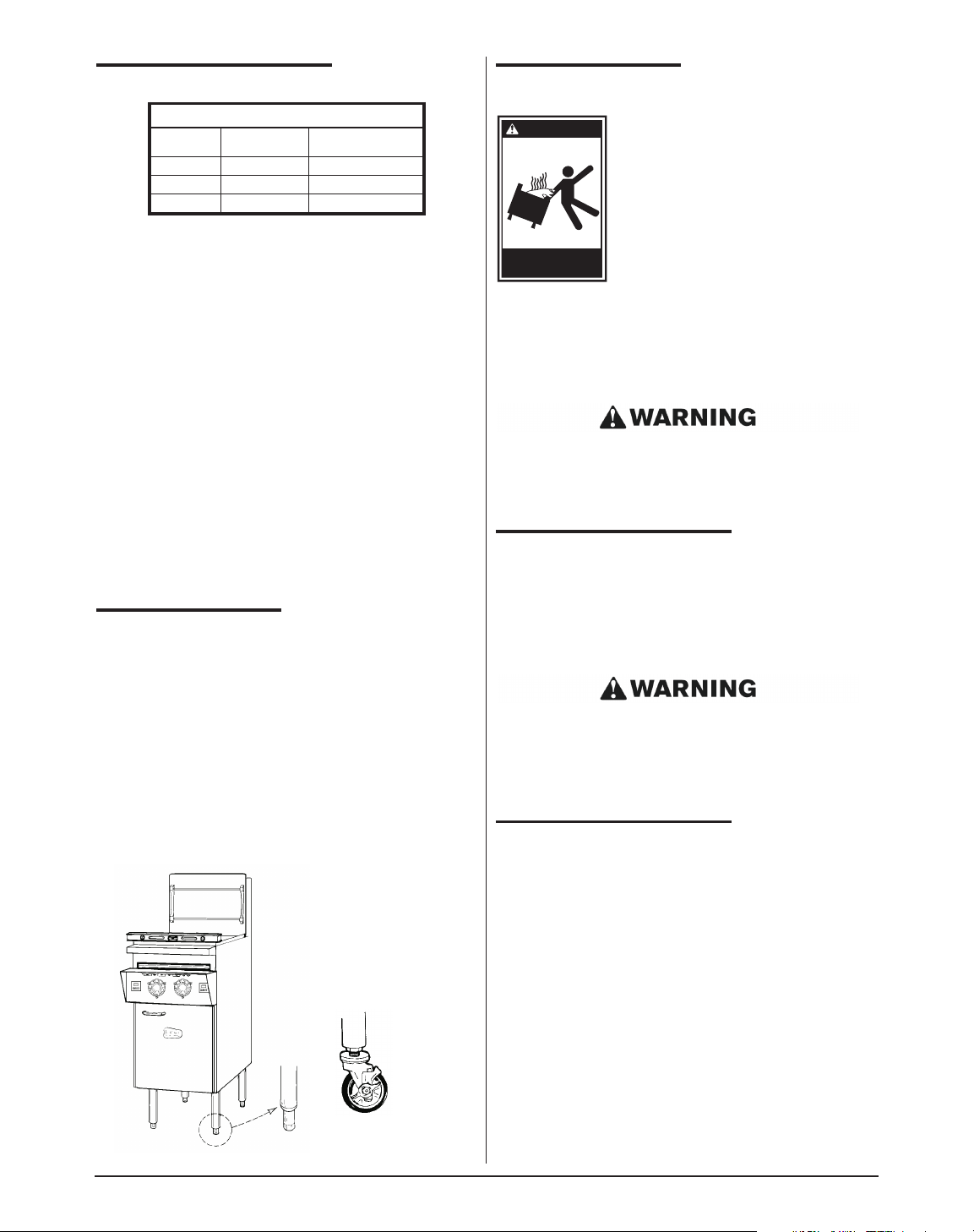
4
POSITIONING
The pasta cooker must be no closer than 6" from any
combustible material. When placed under an exhaust
hood with a fire retardant system it must comply with
ANSI/UL 507-(Latest Edition) and ANSI/NFPA 96(Latest Edition). No frame or restriction can be
constructed around the lower part of the pasta cooker
that would restrict ventilation or air movement into the
pasta cooker. You must insure adequate air supply to
the pasta cooker.
Adequate clearance for servicing and proper operation
must be maintained. Your pasta cooker is designed to
be serviced from the front. Do not place a pasta cooker
next to a deep fat fryer. Hot oil and water can cause an
unstable condition creating a hazardous situation. The
pasta cooker will operate at highest efficiency when
properly leveled. Place a level across the cooker front
panel from left to right, and then front to rear. Screw the
adjustable bullet feet or casters in or out as necessary
until the cooker is as level as possible. Each leg is
adjustable to 3/4". Do not expose more than three
threads on the stem of the caster.
LEVELING
The Pasta System will operate at its highest efficiency
when properly leveled. Place a level on Pasta System
vessel from side to side. For Pasta Systems on legs, the
bottom foot of the leg is adjustable. Turn counter
clockwise to decrease height or clockwise to increase
height until level. For Pasta Systems on casters, the
casters are adjustable by loosening the jam nut and
turning the caster in or out. When the desired level is
reached, tighten the jam nut. Adjustments of more than
3
/4" are not recommended on any caster. The same
procedure should be followed to level the Pasta System
from front to back.
Figure 2-1
RESTRAINING
DEVICES
On Custom Pasta
™
System
installations with casters, casters and
jam nuts must be completely
tightened. Adequate means must also
be provided to limit the movement of
the appliance without depending on
the connector, the quick-disconnect
device or its associated piping to limit
the appliance movement.
Connectors must comply with ANSI Z21.69/CAN1
CAN/CGA 6.16 (latest edition) for connectors for
movable gas appliances. Quick-disconnect devices
must comply with ANSI Z21.41/CAN 1 6.9 (or latest
edition) standard for quick-disconnect devices for use
with gas fuel as applicable.
IF DISCONNECTION OF THE RESTRAINT IS
NECESSARY, IT MUST BE RECONNECTED WHEN
THE CUSTOM PASTA
™
SYSTEM IS RETURNED TO
ITS ORIGINALLY INSTALLED POSITION.
ELECTRICAL CONNECTION
Your pasta cooker has been ordered in either 1 phase
or 3 phase by your dealer. All electrical connections
should be made by a licensed electrician. If necessary
this unit can be field changed from 1 phase to 3 phase
or from 3 phase to 1 phase. Have a qualified electrician
refer to the wire diagram.
ALL ELECTRICAL WIRING LEADING TO THE PASTA
COOKER MUST CONFORM TO LOCAL CODES. BE
SURE THE ON/OFF SWITCH IS IN THE OFF
POSITION BEFORE TURNING THE POWER ON TO
THE PASTA COOKER.
WATER AND DRAIN CONNECTION
The water is to be connected to the 3/8" female pipe
connection on the cabinet back, for auto-fill and the
optional faucet.
Make sure this and all other connections do not leak.
Check your water pressure. The auto-fill system is not
designed to handle pressure greater than 60 psi. Any
pressure greater than this can damage the auto-fill
solenoid or cause the system to fail. If the pressure is
greater than 60 psi a pressure regulator should be
added. The water temperature must not exceed 150°F
(65.6°C). Hot or warm water is not needed due to the
instant recovery of the Custom Pasta™System.
If during operation the boil is killed when water
automatically enters the pasta cooker, turn the water
pressure down until the water is added without killing
the boil. The drain terminates within inches of the floor
and is designed for the standard dump to drain opening.
CLEARANCES
Combustible
Construction
Non-Combustible
Construction
Back 6" 0"
Right Side 6" 0"
Left Side 6" 0"
Caster
WARNING
Restraining devices
required.
Page 7
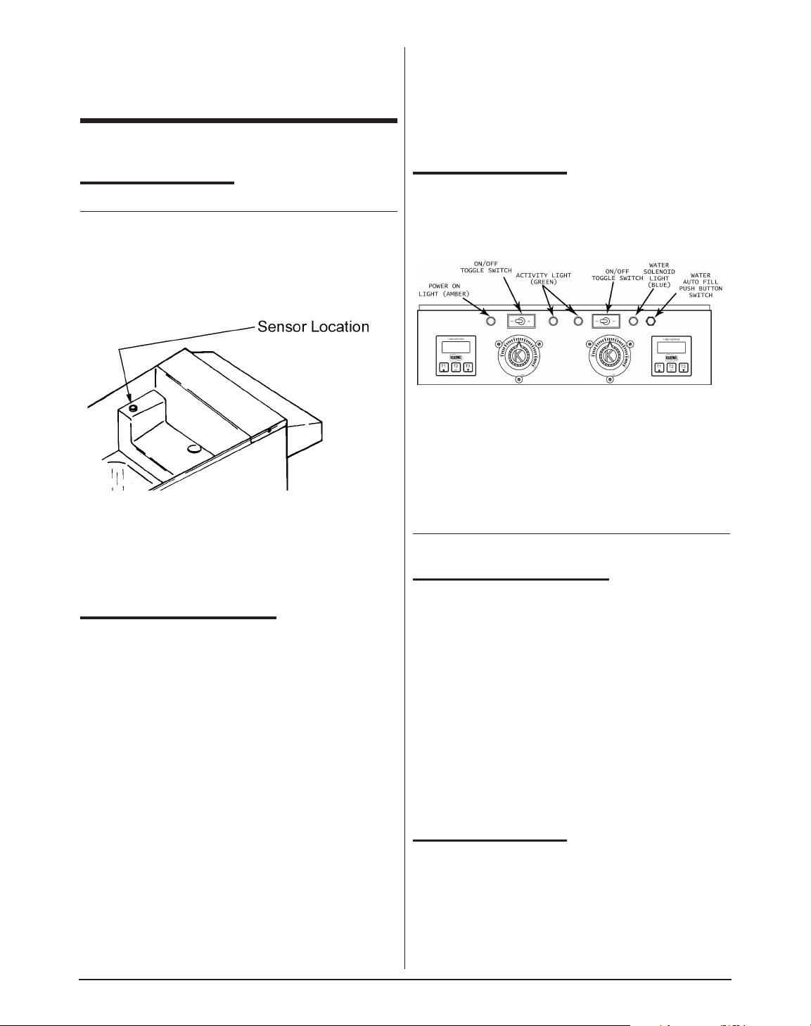
5
In most cases the health department will not allow a
direct connection between the cooker drain and the
floor receptical. Contact your local health department
for specific information in your area.
III OPERATION
FILLING
NOTE: Before filling the Pasta System make certain the
vessel is sanitized, dry and the drain valve is completely
closed.
Figure 3-1
Manual Water Fill Level
When the water fill toggle switch (located between the
green and blue indicating lights) is turned on, the Pasta
System vessel automatically will be filled to the proper
level. If the vessel is being manually filled with water
from a faucet or through the manual fill button, fill to just
below the overflow deck. The black manual fill button is
located to the right of the blue water fill indicating light.
THERMOSTATS
The Keating pasta cooker has two thermostats. This is
to allow maximum control of the boil. The system is
designed so that both thermostats will function together
when called for but one thermostat will act as primary
and hold the water at a rolling boil during cooking as
well as idle time. The two thermostats allow the user to
have complete control over the cooking process.
The right side thermostat will only activate if the left side
thermostat is active. From a cold start all elements and
thermostats will be on and heat the water to a rolling
boil. Once the water has reached a rolling boil the right
side (secondary) thermostat will turn off and the left side
thermostat (primary) will hold the water at a rolling boil.
When product to be cooked is dropped into the pasta
cooker the drop in temperature depends on the
temperature spread between the two thermostats as
determined by the user.
If adding product does not turn on the secondary
thermostat and the water falls below a rolling boil,
increase the setting slightly on the secondary
thermostat. It is not recommended that there be less
than a twenty degree difference between the two
thermostats. Having less than a twenty degree
difference will increase the possibility of a boil over and
cause the pasta cooker to short cycle. The
recommended starting temperatures for the cooker are
212°F (98.8°C) for the primary and 190°F (87.8°C) for
the secondary thermostat. Using these settings with the
knowledge of the operation of this system, the user can
fine tune the settings to fit his specific operation.
INDICATING LIGHTS
Figure 3-2
Custom Pasta System Electric Control Panel
AMBER–shows the power is on.
GREEN–shows the secondary (right)
thermostat is calling for heat from the
center element(s).
BLUE–shows water is filling into the
Pasta System vessel through the Pasta
System water solenoid valve.
NOTE: The black manual water fill button is located
to the right of the blue indicating light.
THE AUTO-FILL SYSTEM
The water temperature must not exceed 120°F (48.8°C).
Control of the water level is fully automatic with the auto-fill
system. The water level is controlled by two circuit boards
attached to the two water level sensors located on the front
of the pot below the spashdeck. Once the water switch is
turned to ON, the pasta cooker will start to fill with water.
The heating elements will not turn on until the water level is
above the bottom sensor. This is an automatic water safety
built into every pasta cooker. This safety prevents the pasta
cooker from accidental heat damage due to low or no
water. The bottom sensor is the low water cut off. The top
sensor is the water level control. Both sensors should be
cleaned on a regular basis to prevent water deposits from
interfering with the sensor reaction. Cleaning should be
done with the brush up and down the sensor tube located
on the right side of the splashdeck.
COOKING
Keating Electric Custom Pasta Systems are designed to
provide maximum production efficiency and deliver high
quality food products. Low-temperature cooking and highly
polished stainless steel mean greater energy savings. Two
thermostats are used to provide instant recovery and to
save energy while water is boiling. The secondary (right)
thermostat calls for additional heat at start up or
occasionally when water is added. Follow cooking
Page 8
6
procedures below for your model.
NOTE: Use of sodium chloride during the cooking
process will have a detrimental effect on the cooker tank
and will void the warranty.
OPERATION OF THIS PASTA SYSTEM SHOULD
BE LIMITED TO PERSONNEL WHO HAVE BEEN
THOROUGHLY TRAINED IN OPERATING
PROCEDURES.
USE ONLY KEATING APPROVED BASKETS IN
YOUR PASTA SYSTEM. NEVER OVERFILL
BASKETS. DO NOT BANG BASKETS ON
BASKET HANGERS OR PASTA SYSTEM
VESSEL.
CARE SHOULD BE TAKEN WHEN LOWERING
BASKETS INTO PASTA SYSTEM TO PREVENT
SPLASHING HOT WATER FROM PASTA
SYSTEM VESSEL.
NEVER LIFT BASKETS DIRECTLY OUT OF THE
PASTA SYSTEM VESSEL WITHOUT DRAINING
AS SEVERE INJURY MAY RESULT.
NOTE: For counter model Pasta Systems, always
check the rear drain operating handle before attempting
to use the Pasta System. A safety switch prevents the
Pasta System from operating if the handle is not pushed
in completely and latched.
A. Standard Pasta System
1. Fill Pasta System as described on page 5 –
Filling.
2. Set primary (left) thermostat to 212°F(100°C)
and secondary (right) thermostat to
190°F(87.8°C).
3. When the water starts boiling, lower baskets
slowly into the hot water.
4. Set timer for left or right side basket, whichever
is being lowered into water.
5. When timer sounds, lift basket out of water.
Place on basket hanger rods on splashback of
Pasta System to allow draining of excess water.
B. Basket-Lift Model
1. Fill Pasta System as described on page 5 –
Filling.
2. Set primary (left) thermostat to 212°F(100°C)
and secondary (right) thermostat to
190°F(87.8°C).
3. Fill basket(s) to proper level and place on upper
basket hanger rods on splashback of Pasta
System.
4. Set timers to desired cooking time using T1, T2
or T3 buttons. (For Programming Timers see
page 7).
5. Start the timer. Basket(s) will automatically
lower into the Pasta System vessel.
6. When cooking cycle is complete, an audible
alarm will sound and the basket(s) will raise
automatically. Allow water to drain before
removing.
DRAINING
ALWAYS SHUT THE PASTA SYSTEM OFF COMPLETELY
BEFORE DRAINING. THE PASTA SYSTEM SHOULD BE
DRAINED ONLY UNDER THE SUPERVISION OF
PROPERLY TRAINED PERSONNEL.
1. Turn off Pasta System and open the door.
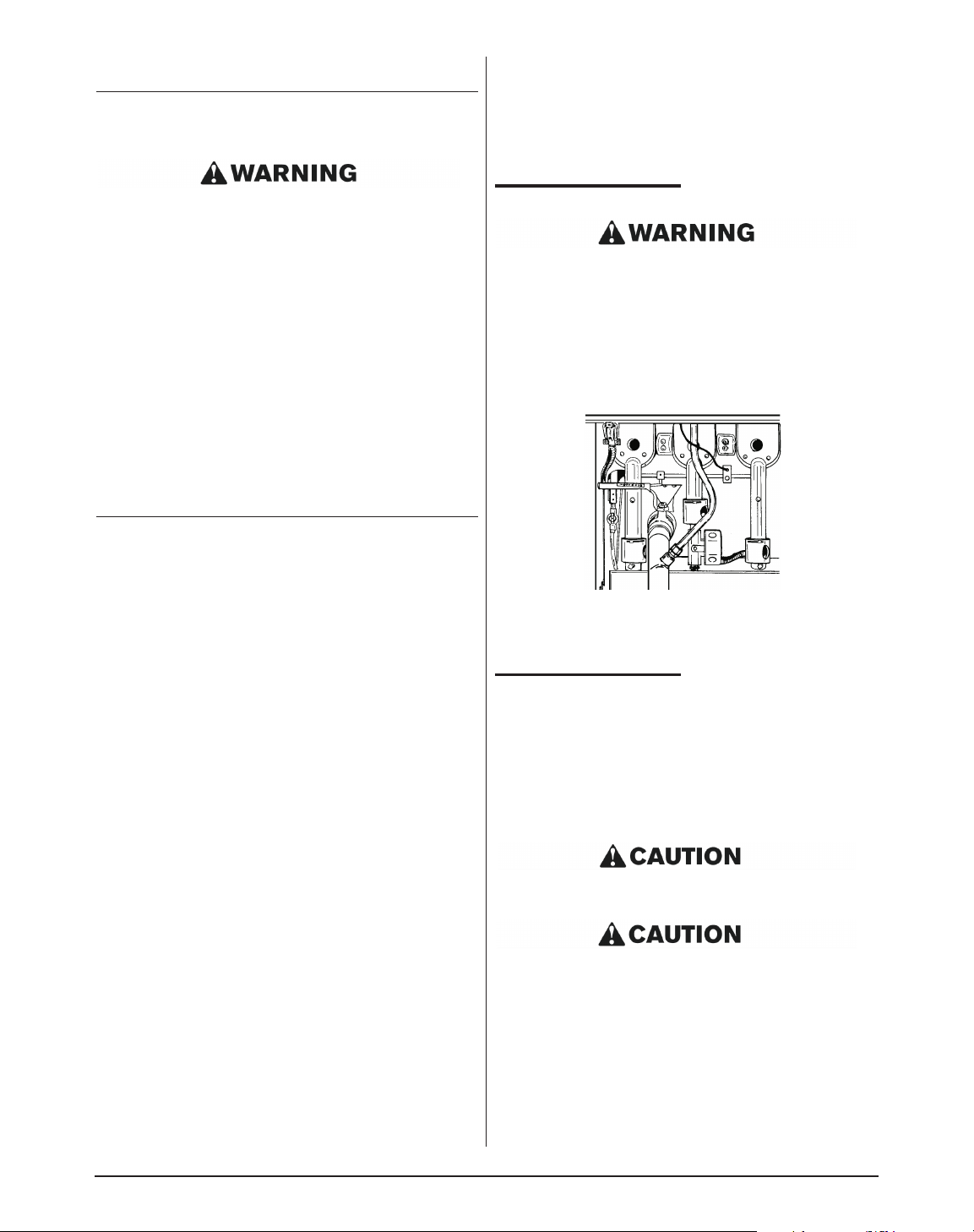
Figure 3-3
Drain, drain valve and overflow tubing
* Gas model shown
2. Slowly turn handle. The drain valve will be
completely open after 1/4 turn.
CLEANING
When cleaning and boiling out your Pasta System, use
white vinegar and Keating Klenzer to keep your Pasta
System in top condition. Once your Pasta System
vessel is clean, use Keating Klenzer, the finest dry
stainless steel polish available, to restore your Keating
Electric Pasta System’ exterior to its original luster.
Disconnect electric power source before cleaning.
To avoid damaging the Pasta System, do not power
wash, spray or hose it down while cleaning.
1. Operator should be outfitted with proper attire
including:
–Water and heat resistant gloves
–Water and heat resistant apron
–Safety goggles
–Water and heat resistant footwear
2. Turn the Pasta System off.
Page 9
7
3. Drain water from Pasta System.
4. Fill Pasta System vessel with water. See page 7 –
Filling.
UNDER NO CIRCUMSTANCES SHOULD THE PASTA
SYSTEM BE LEFT UNATTENDED DURING
BOIL-OUT. TRAINED PERSONNEL MUST BE
PRESENT DURING THE PROCEDURE TO PREVENT
BOIL OVER OR TO TURN OFF THE POWER IF
WATER DROPS BELOW HEAT TRANSFER TUBES.
5. Turn Pasta System on and bring water and a gentle
boil.
6. Once boil has been reached, turn Pasta System off.
7. Dissolve 3 cups of vinegar for every five gallons of
warm water and let soak for one hour. If there is a
large build-up of scale, allow Pasta System to soak
overnight.
8. While soaking, a natural fiber brush may be used to
scrub the tubes and inside walls of Pasta System
vessel.
9. Drain the water and vinegar.
10. Spread Keating Klenzer liberally on elements and
sides of Pasta System vessel.
11. At this point, a non-abrasive scouring pad may be
used to remove any leftover scale.
12. Thoroughly rinse Pasta System vessel with potable
water to remove all Klenzer.
13. Prior to refilling with water, wipe the inside of the
Pasta System vessel making sure all water and
Klenzer has been removed.
14. Close drain valve.
15. Refill the Pasta System with fresh water. See page
7 – Filling.
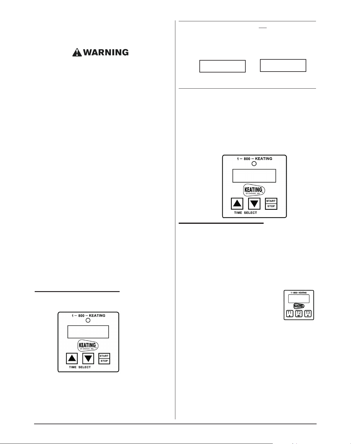
HOW TO PROGRAM THE “KEATING”
ELECTRONIC TIMER – PART #023709
STEP 1 Make certain power to the timer has been
OFF for at least 30 seconds. Then PRESS
and hold down the UP arrow button while
turning the rocker power switch to the ON
position.
NOTE: If power switch does not turn off timers, the
unit must be unplugged (two people may be needed).
The timer will turn ON and the display will now be
indicating
OR
The BEEPER will BEEP 4 times.
NOTE: If STEP 1 was OK, proceed to STEP 2. If not, retry
Step 1 making sure the power was OFF for at least 30
seconds or more.
STEP 2 PRESS all 3 buttons in sequence: left-center-right.
The BEEPER will BEEP when each button is
pressed. If BEEPER does not BEEP, the timer is
defective. STOP TESTING. Reset procedure is
completed when 1:00 appears on the digital
display.
TIMER OPERATING INSTRUCTIONS
DIGITAL TIMERS
PART #056921 – REPLACES PART #023709
The electronic timers provide a clearly visible and
accurate display and are very easy to use.
A. PROGRAMMING
To program the timers, the unit must be in the idle
mode. Press and hold the set button for
approximately two seconds. The display
will show “SEt”. Press the button for the
channel to be programmed. The display
will show the current setting for that
channel. Use the up or down button to
increment or decrement the setting. When the setting is
correct, press and hold the set button again for
approximately two seconds. The display will show "StO"
for approximately two seconds and the timer will return
to normal operation. Repeat the process as necessary
for the other timers.
B. OPERATING LOGIC
When the timer is powered up, the display will show the
time setting for the channel that was operated last and
the relay output contacts will be open. To start a cycle,
press the desired channel button (1-3). The display will
begin to countdown from the preset time setting and the
relay output contacts will close. During the countdown
the colon will flash at a one-second rate. When the
countdown has reached "00:00" the relay output
– – –
– – –
•
•
1:00
1:00
Page 10
8
contacts will open, the display will flash, and the audible
alarm will sound. To cancel the audible alarm, press any
button.
C. PAUSE FEATURE
To pause a cycle in progress, press any button. The
relay output contacts will open, the display will flash,
and the countdown will pause. To resume the
countdown, press any button. The display will resume
the normal countdown and the relay output contacts will
close.
D. CANCELING A CYCLE
To cancel a cycle in progress press and hold any button
for approximately two seconds. The relay output
contacts will open and the display will show the time
setting for the channel last used.
IV MAINTENANCE
PREVENTIVE MAINTENANCE
Preventive maintenance should be done in daily,
weekly, monthly and yearly intervals as necessary.
Following preventive maintenance procedures will help
keep your Pasta System working efficiently. Proper care
and servicing will lead to years of quality performance.
NOTE: The most important part of any maintenance
program is daily cleaning. Ninety percent of any
maintenance problem is directly or indirectly related to
cleanliness.
NOTE: Water level problems caused by the sensors
not being cleaned adequately will not be covered under
warranty.
NOTE: Use of sodium chloride during the cooking
process will have a detrimental effect on the cooker
vessel and will void the warranty.
*High production facilities should be checked more often.
WHEN THE WATER LEVEL FALLS BELOW THE
BOTTOM WATER SENSOR THE HEATING
ELEMENTS WILL TURN OFF. IF THEY CONTINUE
TO HEAT, TURN THE MAIN POWER SWITCH OFF
AND CHECK AUTO-FILL SYSTEM.
LIMITED CALIBRATION
Calibration is not covered under warranty
A. Calibration
NOTE: This procedure can only be used with the
primary (left side) thermostat. When calibrating the
secondary (right side) thermostat you will need:
• One standard flat blade screwdriver.
• One accurate thermometer suitable for boiling water.
NOTE: For best results, water should be clean.
1. Set thermostat to 212°F(190°C).
2. Allow Pasta System to cycle three times.
3. Place an accurate thermometer in the water.
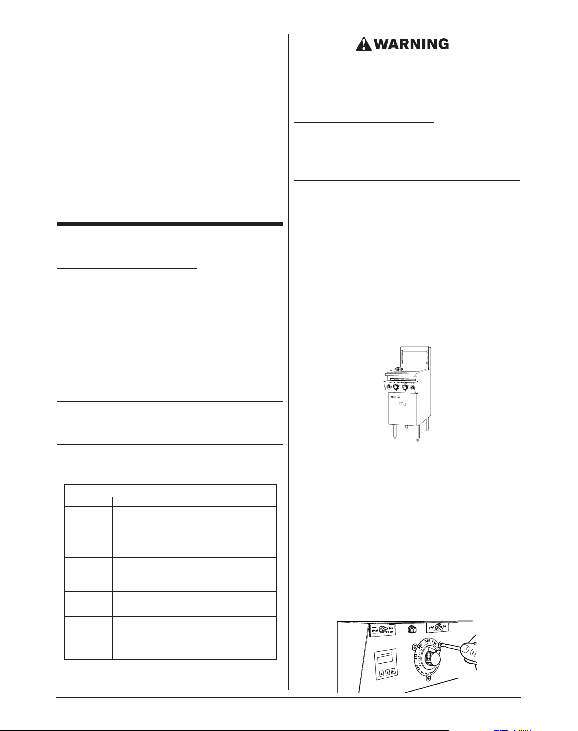
Figure 4-1: Thermometer in water
NOTE: Locate thermometer in same position for
every calibration. Position near primary thermostat
(center) bulb is recommended.
4. If calibration of thermostat is found to be less than
15°F(9.44°C) off, simply loosen three dial plate
retaining screws, rotate dial plate to match
thermometer reading and tighten screws. If the
thermostat is more than 15°F(9.44°C) off then a
qualified service company must be contacted to
have the Pasta System properly calibrated.
Figure 4-2
Thermostat calibration
PREVENTIVE MAINTENANCE CHART
TIME FRAME OPERATOR/OWNER SECTION
Hourly
• Clean sensor tube with a brush
Daily
• Check lights and controls.
• Check water level.
• Clean all baskets.
III
Weekly
• Boil-out Pasta Cooker
(2-3 times/week)
• Drain and clean Pasta Cooker
III
Monthly
• Verify thermostat settings
(primary and secondary)
IV & V
Yearly
QUALIFIED SERVICE
PERSONNEL ONLY
• Check all wire connections.
• Replace suspect wires.
IV & V
Page 11
9
B. The Water Auto-Fill and Low Water Safety Shut-
Off Systems
The water supply connection, located at the bottom rear
of the Pasta System and marked water, is a standard
3
/8”
female pipe connection. The water pressure should be
between 20-60 psi. If the pressure exceeds 60 psi, a
pressure regulator must be used. The water
temperature must not exceed 150°F(65.6°C). Hot or
warm water is not needed due to the instant recovery of
the Pasta System.
Connections suitable for hot water must be used.
All connections must be tested for leaks before
using the Pasta System.
NOTE: For Pasta Systems with casters, flexible hose
must be used to avoid leaking when the Pasta System
is moved for cleaning.
Control of the water level is fully automatic with the
auto-fill system. The water level is controlled by two
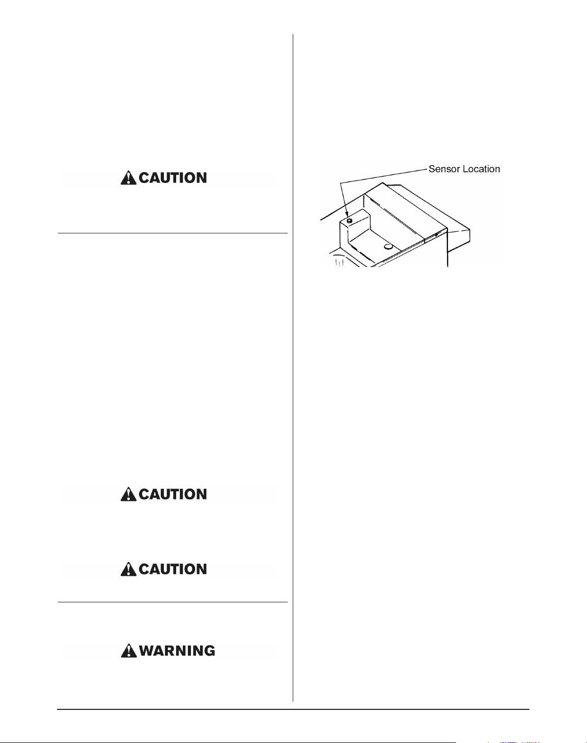
circuit boards and two sensors. The sensors are located
in the tube on the right side of the overflow deck. The
upper sensor controls the water level and the lower
sensor controls the low water safety shut-off system.
Once the water On/Off switch is turned on, the blue light
will come on and start to fill until the water level reaches
the upper sensor. The burners will not come on until the
water level reaches the lower sensor, preventing the
Pasta System from being damaged if there is little or no
water in it. Both sensors must be cleaned with the
sensor brush (like the one provided) on an hourly basis
or whenever starch foams up to maintain the proper
water level. Sensors must be cleaned more often in
areas with hard water, in installations with softened
water (due to the salt in the water) or when oil or salt is
placed in the water for cooking.
The brush must be checked on a regular basis and
replaced whenever it starts to wear.
Do not store the sensor brush in the sensor tube as
it could contact the sensors, which could allow the
water level to drop below the heat tubes and
damage the Pasta System.
Using a worn brush could damage the sensors.
NOTE: Water level problems caused by the sensors
not being cleaned adequately will not be covered under
warranty.
WHEN THE WATER LEVEL FALLS BELOW THE
LOWER SENSOR THE BURNERS WILL SHUT OFF.
IF THEY STAY ON, TURN THE MAIN POWER
ON/OFF SWITCH TO THE “OFF” POSITION AND
CLEAN THE SENSORS THOROUGHLY. IF THE
PROBLEM STILL OCCURS, HAVE THE WATER
AUTO-FILL SYSTEM CHECKED BY A QUALIFIED
SERVICE TECHNICIAN.
Figure 4-3
Sensor Tube Location
Page 12
10
V SERVICE AND PARTS
INFORMATION
THE COOKER MUST BE DISCONNECTED FROM
ITS POWER SOURCE OR SHUT DOWN AT THE
BREAKER PRIOR TO SERVICE.
AUTO-FILL SYSTEM
The auto-fill system allows the automatic addition of
water to the pasta cooker during cooking or idle
function. The system is controlled by the on/off switch
explained in CLEANING. If the system should fail to
allow the pasta cooker to fill with water, check the power
supply to the pasta cooker. If the left side amber
indicating light is not on, check the circuit breaker to the
cooker. If the pasta cooker fails to stop adding water or
fails to turn the elements off, check the water level
sensors. Clean the sensors as stated in PREVENTIVE
MAINTENANCE. If after cleaning, the system still fails it
is possible to adjust the control boards inside the field
wire box.
THIS ADJUSTMENT IS DONE PRIOR TO SHIPMENT
AT THE FACTORY. IT SHOULD ONLY BE ADJUSTED
BY A QUALIFIED SERVICE TECHNICIAN.
The potentionmeter is located on the control board. It is
a black knob with a white triangle imprinted on it. The
potentionmeter adjusts the sensitivity of the probe.
Adjusting this sensor will not increase the depth of the
water. Improper adjustments can effect the operation of
the cooker and cause damage. All boards returned to
Keating are tested. The board marked with a “B” is the
top water level or fill board. The board marked with an
“A” is the safety or low level board. The “A” board is
connected to the bottom sensor and turns the elements
off when the water falls below the level of sensor. The
“B” board is connected to the top sensor and adds water
when the level falls below the probe. Regular cleaning
of these sensors is of the utmost importance.
COOKER HEATING SECTION
The heating section as explained in CONTROL
FEATURES is not that of a fryer. The thermostats
control the heat only to one element except during
heavy use. If the cooker boils over, check the
thermostat setting and calibration. Remember a boil
over is not covered under warranty and the pasta
cooker should never be left unattended. When the
ON/OFF switch on the left side is turned to the ON
position, you will hear one of three contactors click in.
As the thermostats turn the elements on and off, other
contactors will also be heard. Refer to wiring diagram.
WARRANTY REPAIRS
Keating’s warranty begins with the date of isntallation.
In the even that your Pasta System, under warranty,
needs repairs other than routine maintenance or
cleaning, you are requeted to contact Keating of
Chicago Inc. at 1-800-KEATING before calling a local
service company.
ORDERING PARTS
Parts may be ordered by part number by calling Keating
at 1-800-KEATING or your service company. You may
also order online at the Keating Parts Store,
www.keatingofchicago.com.
Refer to the Keating Custom Pasta™System Limited
Warranty for complete service and ordering information.
The model/serial plate is located inside of the door. The
model and serial numbers are necessary when
ordering.
Page 13

11
COMMON PROBLEMS SOLUTIONS (FOLLOW IN SEQUENCE)
Water always filling 1. Clean sensors thoroughly with brush and vinegar.
2. Adjust the sensitivity of the B Board (for the top sensor) fully clockwise.
3. If filling persists, ground out the top sensor (if filling stops, replace sensor –
Part #010212).
4. If filling persists after grounding the sensor, replace the B Board (Part
#001166).
Water never fills 1. Turn water switch (far right) ‘on.’
2. Clean sensors thoroughly with the brush and vinegar.
3. Adjust the sensitivity of the B Board (for the top sensor) fully counter
clockwise (follow instruction sheet).
4. Remove the wire from the top sensor. If filling begins, replace sensor (Part #
010212).
5. If water does not fill, place a jumper wire across terminals A & C on the B
Board. If filling begins, replace B Board (Part # 001166).
6. If water does not fill, replace water solenoid (Part # 008133).
Timers counting down in the
wrong mode (not minutes or
seconds)
1. Reset the timer (see instructions).
Water leaking in the rear of
the pasta cooker
1. Replace fill hose (Part #033495 – sold per foot)
Breakers continue to trip 1. Ensure all wires to the contactors, breakers and elements are tight.
2. Verify water is not getting on any components.
3. Check contactors for proper operation.
4. Check continuity on elements.
5. Replace breaker.
Heating elements won’t
come on
1. Verify operating instructions in the manual.
2. Clean sensors with brush and vinegar.
3. Adjust sensitivity of the A Board (for the lower sensor) fully clockwise (follow
instruction sheet).
4. Place the wire attached to the lower sensor to the ground (if heating begins,
replace sensor – Part #010212).
5. If heating does not being, place a jumper wire across terminals A&C on the A
Board. If heating begins, replace the A Board (Part #001167).
VI SERVICE DIAGNOSIS
TROUBLE SHOOTING
The following diagnosis is only to be used as a guide to qualified service personnel. Keating recommends that
you use a qualified service company. Call 1-800-KEATING if you need assistance in locating a qualified service
company.
Page 14

PROBLEM PROBABLE CAUSE SOLUTION
Pasta Cooker has poor recovery or
runs cold.
a.Over-filling baskets.
b.Thermostat out of calibration.
c. Element is faulty.
d.Thermostat is faulty.
e.Contactor is faulty.
a.Don’t overfill baskets.
b.Calibrate thermostat. See page 4
- Calibration.
c. Replace element.
d.Replace thermostat.
e.Replace contactor.
Contactor chatters. a.Voltage is low to Pasta Cooker.
b.Contactor coil faulty.
c. Connections are loose.
d.Thermostat contacts do not close
properly.
a.Contact your electrician or the
local power company and have the
incoming power checked.
b.Replace contactor.
c. Tighten connections.
d.Replace thermostat.
Basket-Lift mechanism does not
operate.
a.Connections are loose or timer is
faulty.
b.Motor limit switch is faulty.
c. Lift motor is faulty.
d.Actuator is faulty.
e.Control circuit fuse has blown.
f. Relay is faulty.
a.Tighten connections. Replace
timer if it will not operate.
b.Replace limit switch.
c.Replace motor. Specify left or
right side when ordering.
d.Replace actuator.
e.Replace fuse.
f. Replace relay.
Basket-Lift motor runs, but basket
doesn’t move.
a.Cam is slipping on the motor
shaft.
a.Tighten cam onto motor shaft.
Basket-Lift basket goes down, but
won’t go up.
a.Basket-Lift motor limit switch is
misaligned.
a.Align limit switch.
Basket-Lift buzzer won’t shut off. a.Buzzer limit switch is misaligned. a.Align limit switch.
12
COMMON PROBLEMS SOLUTIONS (FOLLOW IN SEQUENCE)
Unit is out of power 1. Check electrical connection.
2. Check fuses.
3. Check Hi-Limit control.
Page 15
VII PARTS LIST
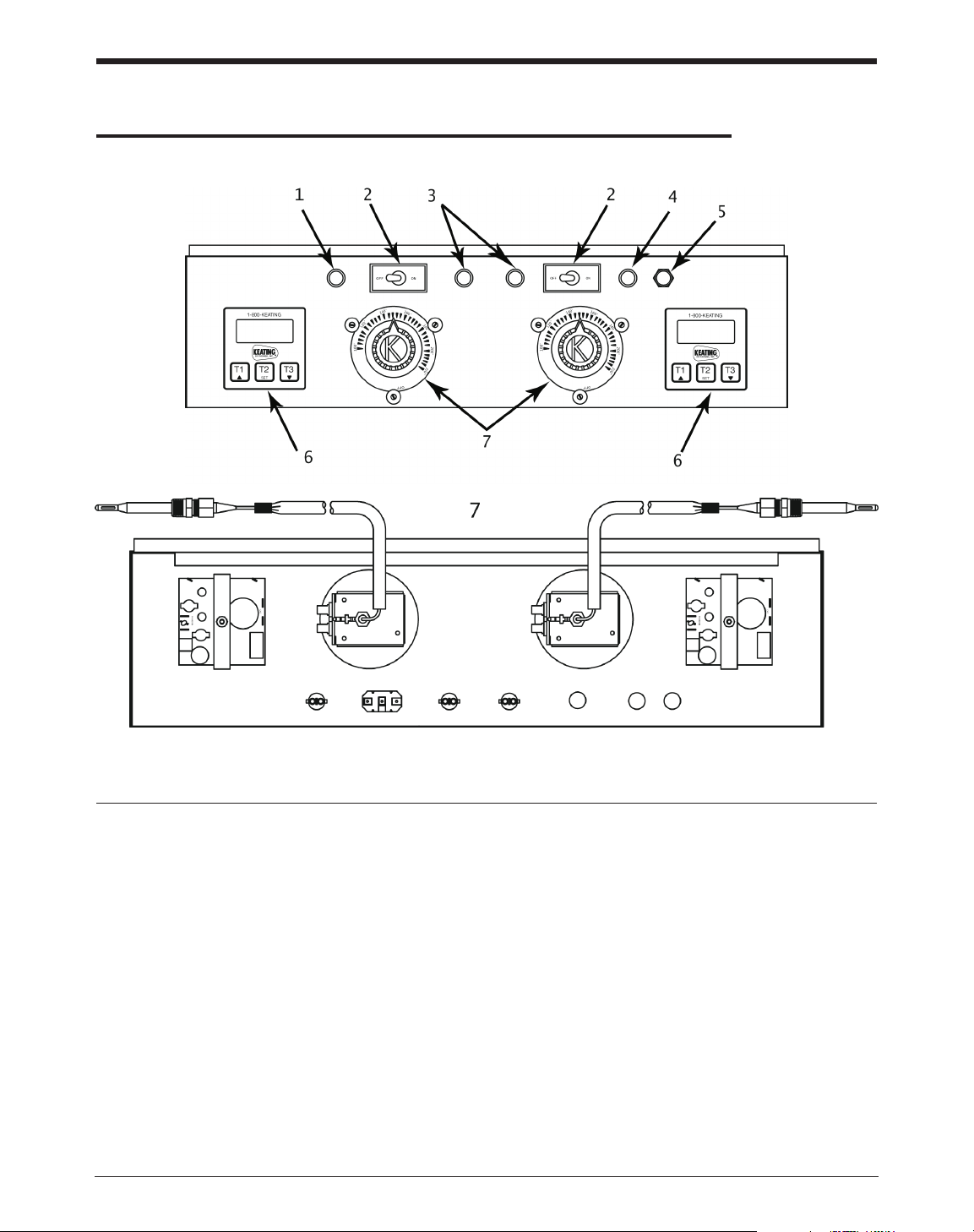
CUSTOM PASTA SYSTEM ELECTRIC CONTROL PANEL ASSEMBLY
13
ITEM # DESCRIPTION QTY PART #
1 INDICATING LIGHT, AMBER, POWER ON 1 031624
2 TOGGLE SWITCH– MAIN ON-OFF 2 004499
3 INDICATING LIGHT, GREEN, THERMOSTAT HEATING 2 010682
4 INDICATING LIGHT, WATER FILLING 1 009256
5 MANUAL WATER FILL BUTTON 1 004304
NUT WITH BOOT 1 009389
6 DIGITAL TIMERS 2 056921
14" BASKET LIFT TIMER (Not Shown) 2 023709
7 THERMOSTAT 2 031466
THERMOSTAT KNOB 2 004163
DIAL PLATE 2 034975
RETAINING SCREWS FOR DIAL PLATE 6 004610
Not Shown HI-LIMIT CONTROL 1 034357
Not Shown LOW WATER SAFETY CONTROL ("A") BOARD 1 001167
Not Shown AUTOMATIC WATER FILL CONTROL ("B") 1 001166
Fig 7-1 Custom Pasta System Electric Control Panel
Page 16
14
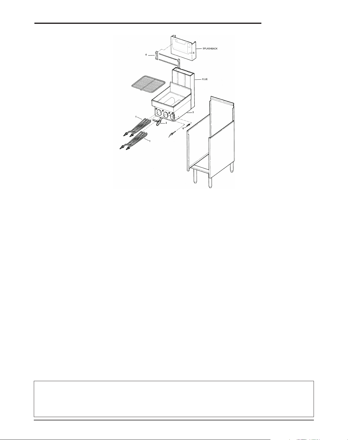
PARTS LIST FOR CUSTOM PASTA SYSTEM
™
ITEM DESCRIPTION MODELS PART # 14 18 20 24
1 HEATING ELEMENT 220V 6500W 14" ONLY 018668 3
1 HEATING ELEMENT 18" & 20" ONLY 004353 2 2
2 DRAIN VALVE – 1" FRONT 14" ONLY 026813 1
2 DRAIN VALVE HANDLE – 1" FRONT 14" ONLY 016387 1
2 DRAIN VALVE – 11/4" FRONT 18", 20" & 24" 016346 1 1 1
TERMINAL BLOCK – 600V 3P 175AMP 034381 1111
CIRCUIT BREAKER 40AMP 1P 012129 4
FUSE 300V 3AMP 004334 2
SOLENOID VALVE 18", 20" & 24" 037033 2 2 2
CONTACTOR 110V 3P 50AMP 016346 1 1 1
TRANSFORMER, STEPDOWN, 004376 1111
220-110V 60Hz
CIRCUIT BREAKER, 50 AMP 3Ø 033891 1111
DOOR CATCH, ROLLER STYLE ALL 004540 1111
WATER FILL SOLENOID ALL 008133 1111
HOSE CLAMP ALL 004167 2222
WATER FILL HOSE CALL 1-800-KEATING
BOLT1/4-20×1/2 SHOULDER WITH FLATS ALL 016782 2224
4 BASKET HANGER MOUNTING AA, BB, TS, CMG
BLOCK (PRE 2000 MODEL)
LEFT 004539 1111
CENTER 003813 1 1 1
RIGHT 004538 1111
4 BASKET HANGER ROD AA, BB, TS, CMG SEE BELOW 2222
(PRE 2000 MODEL)
5 BASKET HANGER 2000 MODEL SEE BELOW 1111
6 WATER SENSOR 010212 1111
ITEM DESCRIPTION MODELS 10x11 14 18 20 24 34x24
4 BASKET HANGER ROD 2/FRYER 003849 003895 003935 003953 003954 011954
5 BASKET HANGER 2000 MODEL 018477 018556 018559 018562
Page 17

15
PARTS LIST FOR 14" DROP-IN CUSTOM PASTA SYSTEM
DESCRIPTION QTY PART#
THERMOSTAT DIAL PLATE 2 034975
AMBER INDICATING LIGHT 1 031624
GREEN INDICATING LIGHT 2 010682
BLUE INDICATING LIGHT 1 009256
PUSH BUTTON MOMENTARY SWITCH 1 004304
TOGGLE SWITCH – ON-OFF 2 004499
THERMOSTAT KNOB 2 004163
THERMOSTAT 2 031466
HEATING ELEMENT 2 002761
DRAIN VALVE – 1" FRONT 1 026813
DRAIN VALVE HANDLE – 1" DRAIN 1 016387
PARTS LIST FOR 18" CUSTOM PASTA SYSTEM
DESCRIPTION QTY PART#
HEATING ELEMENT 2 004353
SOLENOID VALVE 1 010608
CONTACTOR 1 011225
DRAIN VALVE 1
1
/4" 1 016346
HIGH LIMIT 1 028325
“A” BOARD 1 001167
“B” BOARD 1 001166
WATER SENSOR 1 010212
WATER SOLENOID 1 031906
DIGITAL TIMER 2 023709
TRANSFORMER 1 004376
CIRCUIT BREAKER 1 033891
TOGGLE SWITCH – ON-OFF 2 004499
PUSH BUTTON SWITCH – MOMENTARY 1 004501
AMBER INDICATOR LIGHT 1 031624
BLUE INDICATOR LIGHT 1 009256
GREEN INDICATOR LIGHT 2 009375
THERMOSTAT 2 031466
Page 18
16
VIII WIRING DIAGRAMS
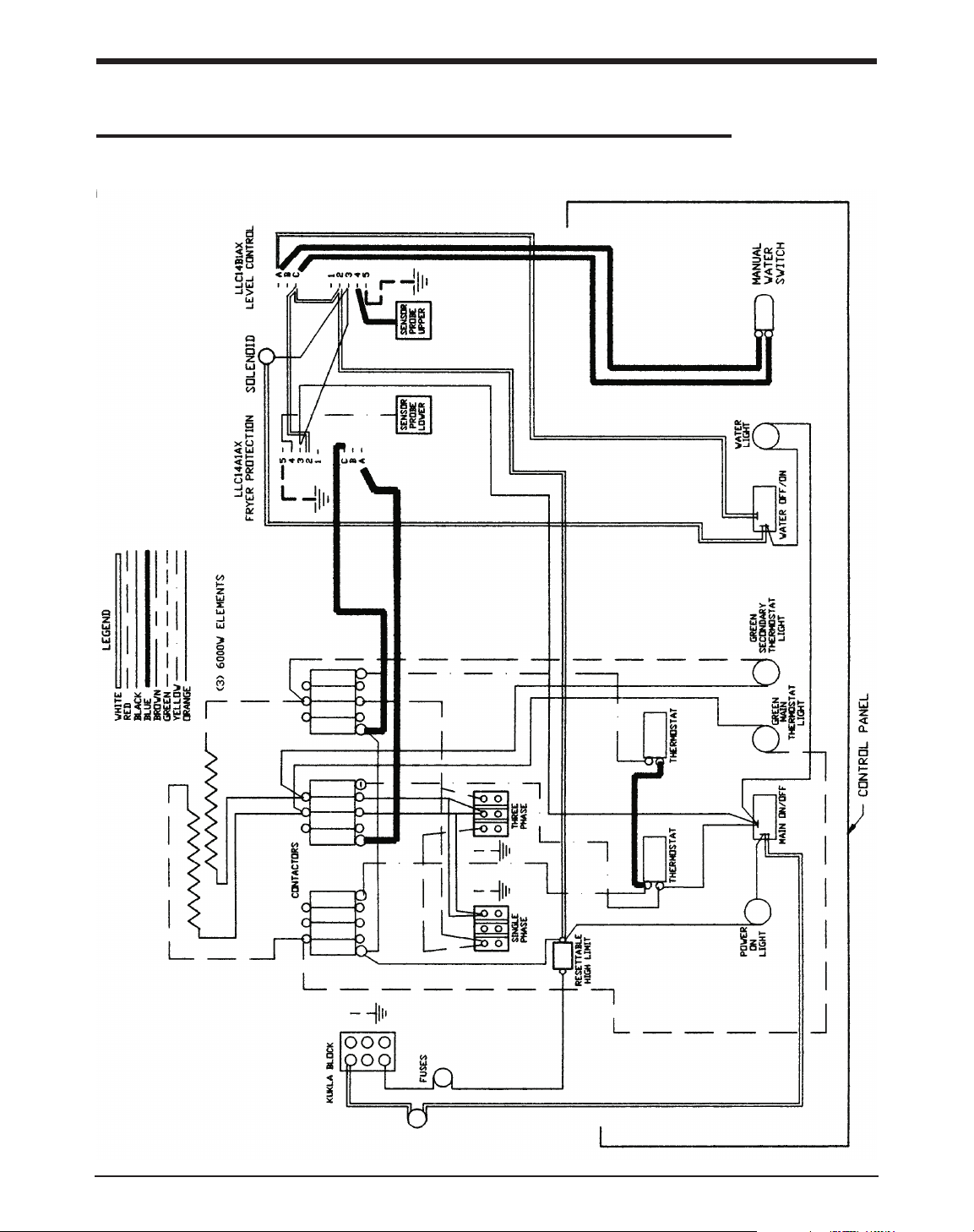
14" ELECTRIC PASTA 2-THERMOSTAT WIRING DIAGRAM (WITHOUT TIMERS)
Page 19
17
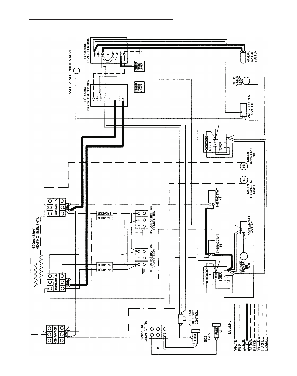
14" ELECTRIC PASTA WITH 138 TIMERS WIRING DIAGRAM
Page 20
18
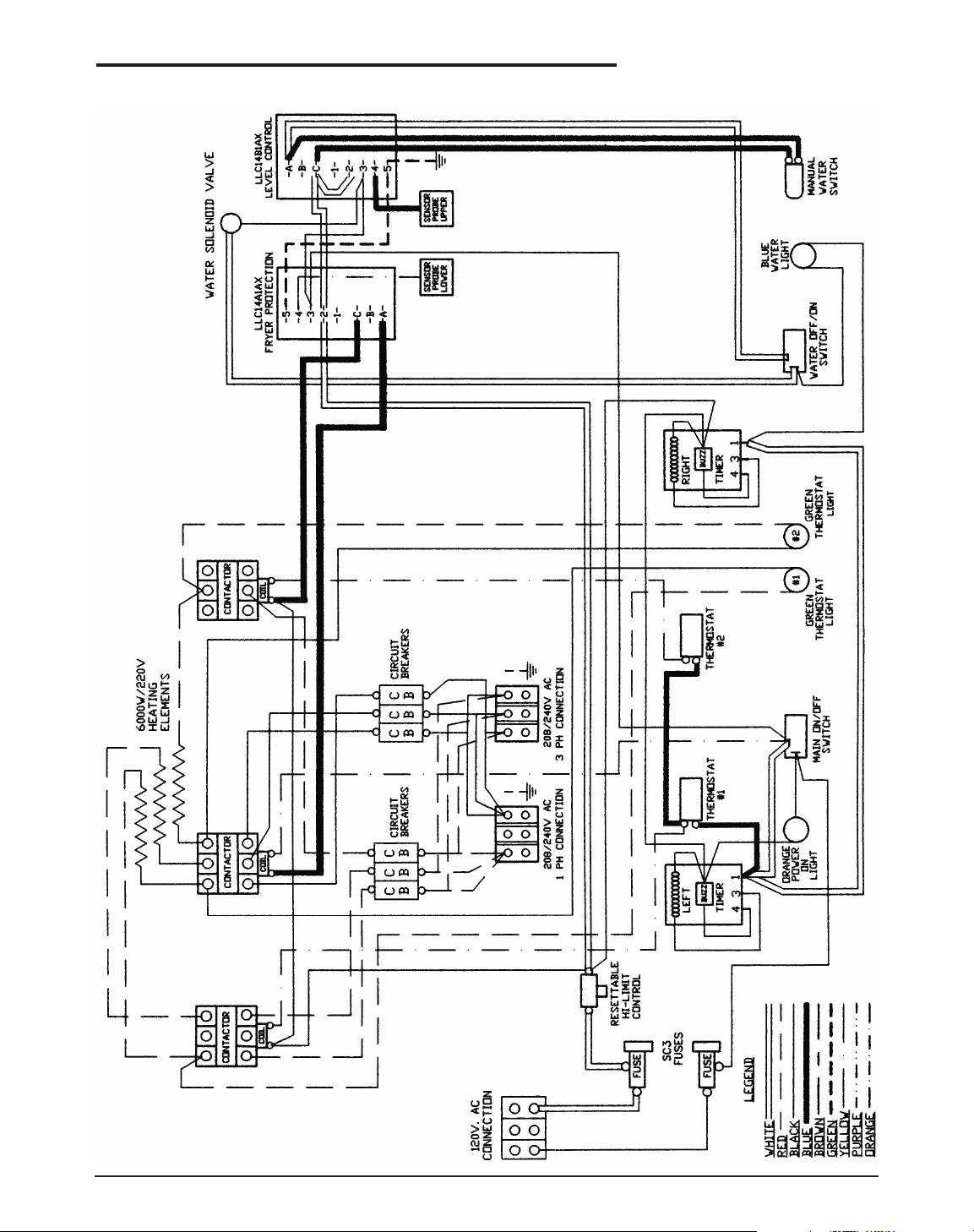
18" & 20" ELECTRIC PASTA WITH 138 TIMERS WIRING DIAGRAM
Page 21
19
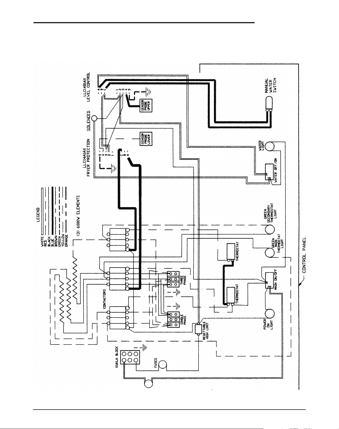
18" ELECTRIC PASTA 2-THERMOSTAT WIRING DIAGRAM (WITHOUT TIMERS)
Page 22
LIMITED WARRANTY
Keating Of Chicago, Inc. ("Keating”) warrants to the original purchaser. ("Customer"), all new Keating Fryers, Filter Systems, Griddles, Keep Krisp
®
, Custom Pasta Systems, Top-Side™ Cookers, Computer Timers, Fryer &
Pasta Vessels, and Keating replacement parts ("products") installed after June 1, 1994 to be free to defects in material or workmanship, subject to the following terms and conditions.
LENGTH OF WARRANTY
All products other than Fryer & Pasta Vessels and replacement parts shall be warranted for a period of one year from the date of original equipment installation. Keating replacement parts are warranted for a period of ninety
days from the date of installation. Fryer & Pasta Vessels are warranted as described below.
FRYER & PASTA VESSEL WARRANTY
Fryers purchased after June 1, 1994 carry a prorated vessel warranty on defects in materials or workmanship to the Customer based on the following scale:
Time from Installation Date Fryer Vessel Warranty Credit
13-60 months 100%
61-72 months 80%
73-84 months 60%
85-96 months 40%
97-108 months 20%
109-120 months 10%
The credit for the defective fryer & pasta vessel shall be applied against the cost of the replacement vessel, utilizing Keating's then current price, upon return of the vessel to Keating, (Freight to be paid by Keating within
the first 2 months only), only during the first 60 months as described above, subject to the limitations described below.
LIMITATIONS OF LIABILITY
In the event of warranty claim or otherwise, the sole obligation of Keating shall be the repair and/or replacement at the option of Keating of the product or component or part thereof. Such repair or replacement shall be
at the expense of Keating except that the Customer shall pay the following expenses: all freight and labor expense for Keating replacement parts for all other products, mileage exceeding 50 miles or travel more than one
hour, labor costs of more than one person, overtime rates, truck charges, difference between ground and other mode of transportation, and holiday charges. Any repair or replacement under this Limited Warranty does not
constitute an extension of the original warranty for any period for the product or for any component or part thereof. Parts to be replaced under this Limited Warranty will be repaired at the option of Keating with new or
functionally operative parts. Keep Krisps and Computer Timers must be returned to Keating for warranty repair or replacement. Field repairs of those items are not authorized.
THE LIABILITY OF KEATING ON ANY CLAIM OF ANY KIND, INCLUDING CLAIMS BASED ON WARRANTY, EXPRESSED OR IMPLIED, CONTRACT, NEGLIGENCE, STRICT LIABILITY OR ANY
OTHER THEORIES SHALL BE SOLELY AND EXCLUSIVELY THE REPAIR OR REPLACEMENT OF THE PRODUCT AS STATED HEREIN, AND SUCH LIABILITY SHALL NOT INCLUDE, AND CUSTOMER
SPECIFICALLY RENOUNCES ANY RIGHTS TO RECOVER, SPECIAL, INCIDENTAL, CONSEQUENTIAL OR OTHER INJURIES TO PERSONS OR DAMAGE TO PROPERTY, LOSS OF PROFITS OR
ANTICIPATED PROFITS, OR LOSS OF USE OF THE PRODUCT.
If any oral statements have been made regarding the Keating products, such statements do not constitute warranties and are not part of the contract sale. This Limited Warranty constitutes the complete, final and exclusive
statement with regard to warranties.
THIS LIMITED WARRANTY IS EXCLUSIVE AND IS IN LIEU OF ALL OTHER WARRANTIES WHETHER WRITTEN, ORAL, STATUTORY OR IMPLIED, INCLUDING BUT NOT LIMITED TO ANY
WARRANTY OF MERCHANTABILITY OR FITNESS FOR PARTICULAR PURPOSE OR WARRANTY AGAINST LATENT DEFECTS.
E
XCLUSIONS
The warranties provided by Keating of Chicago, Inc. do not apply in the following instances:
1. Defects arising out of or resulting from improper installation or maintenance, abuse, misuse, modification or alteration by unauthorized service personnel, or any other condition not attributable to a defect in material or
workmanship. Proper installation and maintenance are the responsibility of the installer and Customer, respectively. Proper installation and maintenance procedures are prescribed by the Keating Service Manual.
2. In the event that the product was damaged after leaving the factory due to flood, fire, other acts of God or accident, damage during shipment should be reported to the carrier and is not the responsibility of Keating.
3. In the event the serial number or rating plate has been removed from the product or altered.
4. On parts which would normally be worn or replaced under normal conditions, including but not limited to electric bulbs, fuses, interior and exterior finishes, gaskets and radiants.
5. With regard to adjustments and calibrations such as leveling, tightening of fasteners or plumbing connections, improper gas pressure or improper electrical supply, the checking of and changes in adjustment and
calibrations are the responsibility of the installer. Proper installation procedures are prescribed by the Keating Service Manual.
6. In the event of unauthorized repairs or alterations to the Keating product.
7. With the use of sodium chloride in pasta vessels or harsh chemicals in fryer or pasta vessels.
O
THER TERMS AND
CONDITIONS
The Customer must provide proof of purchase from Keating.
This Limited Warranty is valid in the 50 United States, its territories, and Canada, and is void elsewhere.
Keating products are sold for commercial use only. If any Keating product is sold as a component of another product or used as a consumer product, such Keating product is sold As Is without any warranty.
If any provision of this Limited Warranty is held to be unenforceable under the law of any jurisdiction, such provision shall be inapplicable in such jurisdiction, and the remainder of the warranty shall remain unaffected.
Further in such event, the maximum exclusion or limitation allowable under applicable law shall be deemed substituted for the unenforceable provision.
This Limited Warranty shall be governed by and construed in accordance with the laws of the State of Illinois.
TO SECURE WARRANTY SERVICE
All repair services under this Limited Warranty must be authorized by Keating or performed at Keating. Authorization may be obtained by calling 1-800-KEATING within the Continental United States, Alaska, Hawaii,
Puerto Rico and Canada during normal business hours (8 a.m. through 5 p.m. Central Time, Monday through Friday). When calling, please have the following information available: (1) name, address and
telephone number of the Customer; (2) location of product, if different; (3) name, model number and serial number of the product; (4) installation date; and (5) description of defect. Keating will then issue a service
authorization work order number to one of its approved independent servicing organizations, or request the product or part be shipped to Keating for repair or replacement, as appropriate. Any defective part subject to a
claim under this Limited Warranty must be shipped freight prepaid to Keating for testing and examination. Keating's decision as to the cause and nature of any defect under this Limited Warranty shall be final.
KEATING
KEATING OF CHICAGO, INC., 1-800-KEATING WWW.KEATINGOFCHICAGO.COM
REFILE/warranty 8/07
WARRANTY
Page 23

KEATING LIMITE D WARRANTY CARD
PLEASE COMPLETE AND MAIL AT ONCE–WARRANTY IS NOT IN EFFECT UNTIL CARD IS RETURNED
WARRANTY REGISTRATION IS ALSO AVAILABLE ONLINE FOR YOUR CONVENIENCE
COMPANY: __________________________________________________________________________________________________________
ADDRESS: ____________________________________________________________________________________________________________
CITY: ____________________________________________________________________ STATE: ______________ ZIP: __________________
DEALER: ______________________________________________________________________________________________________________
DATE OF PURCHASE: ____________________________________________________ INVOICE NUMBER:__________________________
SERIAL NUMBER:
______________________________ FRYER FILTER SYSTE M GRIDDLE
REMARKS:
____________________________________ TOP-SIDE COOKER HOT PLATE CUSTOM PASTA
I HAVE READ THE INSTALLATION AND OPERATION INSTRUCTIONS.
SIGNED: ________________________________________________________________________ DATE:
__________________________
“Serving Those Who Serve The Very Best”
®
SERVICE INFORMATION
If you have a service related question call 1-800-KEATING.
Please state the nature of the call; it will ensure speaking with the appropriate person.
Have your serial and model number available when ordering parts.
KEATING OF CHICAGO, INC.
8901 W. 50th Street, McCook, Illinois 60525-6001
Phone: (708) 246-3000 FAX: (708) 246-3100
Toll Free 1-800-KEATING (In U.S. and Canada)
www.keatingofchicago.com
*As continuous product improvement occurs, specifications may be changed without notice.
 Loading...