

Page 1

SERIES 2006 FRYER MANUAL
Keating’s INCREDIBLE FRYING MACHINE
®
READ AND SAVE THIS MANUAL FOR FUTURE REFERENCE
Record the Model No. and Serial No. of this Incredible Frying Machine®in the space provided below.
Serial No. __________________________
Model No. __________________________
Keep these numbers for future reference
IMPORTANT: Keep a copy of your bill of sale. The date on the bill establishes the warranty period should service be
required. If service is performed, it is in your interest to obtain and keep all receipts. Keating commercial fryers are
intended for other than household use.
1-800-KEATING
www.keatingofchicago.com
CONTENTS:
This Owner’s Guide provides specific operating instructions for your model. Use the Incredible Frying Machine
®
only
as instructed in this Service Guide.
SECTION IV MAINTENANCE
Warranty Repairs............................................................................9
Preventive Maintenance ................................................................9
Oil Breakdown................................................................................9
Thermostat Calibration ..................................................................9
Thermostat Bulb Positioning ....................................................9-10
SECTION V SERVICE DIAGNOSIS
Thermostat Test............................................................................10
Flame Adjustment ........................................................................10
SECTION VI SERVICE
Trouble Shooting Charts ........................................................11-14
SECTION VII PARTS LIST
Ordering Parts ..............................................................................15
Warning and Operating Plates ....................................................15
IFM Gas Fryer Model 2000 Parts List ..........................................15
IFM Gas Fryer Model 2000 Assembly I ......................................16
IFM Gas Fryer Model 2006 Parts List ..........................................17
IFM Gas Fryer Model 2006 Assembly II ......................................18
IFM Gas Fryer Assembly III..........................................................19
IFM Control Panel Parts List ..................................................20-25
IFM Burner Assembly Parts List ..................................................26
Basket Lift Assembly Parts List ..................................................27
SECTION VIII WIRING DIAGRAMS
14IFM Wiring ..........................................................................28-39
Warranty ......................................................................................40
SECTION I INTRODUCTION
General ..........................................................................................1
Standard Features..........................................................................1
Standard Accessories ....................................................................1
Options ..........................................................................................1
Ratings ..........................................................................................1
Model Variations ............................................................................1
Safety Precautions......................................................................1-2
SECTION II INSTALLATION
Damage During Shipment..............................................................3
Installation ......................................................................................3
Leveling ..........................................................................................3
Restraining Devices........................................................................3
Gas Connection ............................................................................4
Electrical Connection ....................................................................4
Gas Leak Testing............................................................................4
Gas Pressure..................................................................................5
SECTION III OPERATING THE FRYER
Filling ..............................................................................................5
Lighting ......................................................................................5-6
Cooking ..........................................................................................6
Shutdown ......................................................................................6
Digital Timers ..............................................................................6-7
Draining ..........................................................................................7
Cleaning and Boil-Out ................................................................7-8
017411 IFM 2006 1108
Page 2
POST THIS LABEL IN A
PROMINENT LOCATION ON
YOUR UNIT
IMPORTANT
IN THE EVENT A GAS ODOR IS DETECTED,
SHUT DOWN UNITS AT MAIN SHUT OFF VALVE
AND CONTACT THE LOCAL GAS COMPANY OR
GAS SUPPLIER FOR SERVICE.
FOR YOUR SAFETY
DO NOT STORE OR USE GASOLINE OR OTHER
FLAMMABLE VAPORS OR LIQUIDS IN THE VICINITY
OF THIS OR ANY OTHER APPLIANCE.
*As continuous product improvement occurs, specifications may be changed without notice.
IFM Model 2006 0107 9/07
IMPROPER INSTALLATION, ADJUSTMENT,
ALTERATION, SERVICE OR MAINTENANCE CAN
CAUSE PROPERTY DAMAGE, INJURY OR DEATH.
READ THE INSTALLATION, OPERATING AND MAINTENANCE INSTRUCTIONS THOROUGHLY BEFORE
INSTALLING OR SERVICING THIS EQUIPMENT.
WARNING
Do not store flammable
liquids near this or any
other appliance.
WARNING
Improper installation
can cause damage,
injury or death.
Page 3
INTRODUCTION
Keating’s Incredible Frying Machine®(IFM) are
designed to give maximum production efficiency, delivering high quality food products. The following design
features are incorporated in Keating’s Incredible Frying
Machine
®
(IFM).
STANDARD FEATURES
• Highly polished stainless steel fryer vessel
• Highly polished stainless steel front
• Highly polished stainless steel heat transfer tubes
• Highly polished stainless steel thermostat bulb
• Highly polished stainless steel Hi-Limit bulb
• Complete stainless steel cabinet
• True Cold Zone for proper sedimentation
• Grid screen over heat transfer tubes
• 1" full port front drain valve
• Patented accurate temperature control system ±2°F
• Ideal 35" working height
• 3/4” NPT gas connection on single fryers
• One pair of split baskets or one full-size basket
• Patented burner design
• Spark Ignition system
• 100% proof of air flow safety shut-off
• 100% proof of flame safety shut off
• Digital timers (2) (where applicable)
• Gas and air adjustments
• Gas pressure test port
• Blower grease filter (easily accessible from front)
• Easy access for servicing from front of fryer
• Burner, blower and Hi-Limit indicating lights
• Insulated fryer vessel
• Heat recirculation for higher efficiency and lower flue
temperature
• Black heat tube interiors for optimum heat transfer
• Instant-On
™
ignition system (where applicable)
• 120 VAC 9' neoprene cord with 3-pronged grounded
plug
• Instant recovery to cooking temperature
• High temperature stainless steel flue lining
• 100% factory testing
STANDARD ACCESSORIES
• Keating Klenzer Sample
• Drain clean out rod
OPTIONS
• Natural Gas or Propane
• Automatic Basket-Lift
• Cooking Computer
RATINGS
• 14" fryer vessel - 38 lb. oil capacity
• 18" fryer vessel - 68 lb. oil capacity
• 20" fryer vessel - 100 lb. oil capacity
• 7" W.C. (Natural Gas) or 11” W.C. (Propane) Line
Gas Pressure.
• 3" WC (Natural Gas) or 10" WC (Propane) manifold
gas pressure.
• 3/4" gas supply pipe recommended
MODEL VARIATIONS
Basket-Lift Model: Basket-Lift Model Fryers come
with all the same features as the standard models. The
Basket-Lift mechanism lowers the baskets of food into
the oil when the timer button is pressed and raises the
baskets when the cooking cycle is complete. Split
baskets are required for these models.
CPU Model: CPU Incredible Frying Machine (IFM)
have the same input as the standard models. A
programmable computer replaces the two timers and
thermostat.
SAFETY PRECAUTIONS
THIS SYMBOL WARNS YOU THAT SERIOUS
BURNS OR OTHER INJURIES MAY RESULT IF
SAFETY INSTRUCTIONS ARE NOT FOLLOWED.
• This service manual should be retained in a safe
place for future reference. The installation of your
new fryer must conform to local codes or in the
absence of local codes, with the current National
Fuel Gas Code ANSI Z223.1/NFPA 54 (latest
edition), Natural Gas Installation Code CAN/
CGA-B149.1 or Propane Installation Code CAN/
CGA-B149.2.
• Your ventilation hood, when installed, must conform
to the current ANSI/NFPA 96 standard (latest
edition).
• No frame or restriction shall be constructed around
the fryer that will restrict air movement into the
fryer’s combustion area or prevent proper
ventilation.
• Keating fryers are designed to operate on the gas
fuel specified on the serial plate and must not be
operated with another gas fuel. They cannot be
converted to another gas fuel by turning or engaging
a switch.
1
Page 4
DO NOT STORE OR USE GASOLINE OR OTHER
FLAMMABLE VAPORS AND LIQUIDS IN THE
VICINITY OF THIS OR ANY APPLIANCE.
You will post, in a prominent location, instructions to be
followed in the event the user smells gas. This
information shall be obtained from your local gas
supplier.
IMPORTANT: IN THE EVENT A GAS ODOR IS
DETECTED, SHUT DOWN UNIT AT MAIN SHUT-OFF
VALVE AND CONTACT THE LOCAL GAS COMPANY
OR GAS SUPPLIER FOR EMERGENCY SERVICE.
• Suitable for installation on non combustible floors.
• You must maintain this appliance free and clear from
combustibles.
• You must maintain the following minimum
clearances from combustible and noncombustible
construction:
• You must install this appliance at least 16 inches
away from any open flame.
• Adequate clearance for servicing and proper
operation must be maintained. Your fryer is designed
to be serviced from the front.
• Keating commercial fryers are intended for other
than household use.
• ALWAYS instruct new employees on proper fryer
operation.
• A fryer should be operated ONLY by properly trained
personnel.
• ALWAYS turn fryer off each night.
• ALWAYS disconnect fuel source before servicing.
• NEVER leave a fryer unattended during operation.
• NEVER move a fryer when full of hot oil.
• NEVER introduce objects or liquids into fryer, while
operational, which are not designed or made for
cooking.
• THIS FRYER MAY NOT BE ALTERED, MODIFIED
OR CHANGED IN ANY WAY.
The State of California enacted the California Safe
drinking water and Toxic Enforcement Act of 1986,
(Prop. 65), which “prohibits any person in the course of
doing business from knowingly and intentionally
exposing any individual to a chemical known to the State
of California to cause cancer or reproductive toxicity
without first giving clear and reasonable warning to such
individuals.” The Governor’s Scientific Advisory Panel
added carbon monoxide
to the list of hazardous
chemicals known to cause reproductive harm.
Carbon monoxide would not be present in
concentrations that would pose a “significant risk” to the
consumer when the equipment is installed, operated and
maintained as follows:
• Installed in accordance with all local codes, or in the
absence of local codes, with the current National Fuel
Gas Code ANSI Z223.1/NFPA 54 (latest edition).
• Installed under a properly designed operating exhaust
hood.
• Connected to the type of gas for which the appliance
is manufactured.
• In-line pressure regulator, not supplied by Keating,
must be installed outside the appliance to maintain
proper incoming gas pressure (7” W.C. Natural, 11”
W.C. L.P.).
• The appliance is adjusted for the manifold pressure
marked on the serial plate.
• Adequate air supply to the appliance.
• The equipment is operated in the manner intended
using the proper utensils.
• Keep the equipment clean and have it checked
periodically.
• Burner air adjustments, mechanical maintenance and
repairs must be performed by qualified service
personnel.
If the equipment is not installed, operated and
maintained in accordance with the above,
concentrations of carbon monoxide in excess of the
established limits could be present in the kitchen
environment.
Clearances
Combustible
Construction
Noncombustible
Construction
Back 6" 0"
Right Side 6" 0"
Left Side 6" 0"
2
Page 5
INSTALLATION
This fryer MUST be installed, inspected, calibrated and
serviced by qualified and/or certified and/or licensed
service personnel - you may void your Keating
warranty if installation is not completed per local,
national and Keating specifications. Contact your
dealer for assistance.
DAMAGE DURING SHIPMENT
The fryer has been assembled, tested and inspected at
the factory. Upon arrival, the complete fryer should be
checked for any damage that may have occurred
during shipment.
The carrier is responsible for all damage in transit
whether visible or concealed. Do not pay for the freight
bill or sign the Bill of Lading until the fryer has been
thoroughly checked for damage. If concealed damage
is found later, contact the carrier immediately to file a
claim.
What to do if equipment arrives damaged:
VISIBLE LOSS OR DAMAGE - Be certain to note this
on the freight or express receipt and have it signed by
the delivery person.
FILE CLAIM FOR DAMAGES IMMEDIATELY Regardless of extent of damage. This claim must be
filed with the carrier.
CONCEALED LOSS OR DAMAGE - If damage is
noticed when equipment is unpacked, notify the freight
company immediately, and file a “concealed damage
claim”. This MUST be done immediately. Be sure to
retain the shipping container for inspection.
Keating does not assume responsibility for Loss OR
Damage incurred in transit. Keating’s sole
responsibility in such cases will be to provide support in
determining the extent of the parts, labor, and cost
thereof needed to return said equipment to new
condition.
INSTALLATION
Installation must conform with local codes or, in
absence of local codes, with the current National Fuel
Gas Code Z223.1/NFPA 54(latest edition), Natural Gas
Installation CAN/CGA - B149.1 or Propane Installation
Code CAN/CGA-B149.2. When pressure testing at test
pressures less than or equal to 1/2 psig (3.45 KPA),
fryer must be isolated from gas supply piping. When
pressure testing at test pressures above 1/2 psig (3.45
KPA), fryer must be disconnected from gas supply
piping system.
Counter model and floor model fryers must be
restrained to prevent tipping when installed in order to
avoid splashing, spilling, etc. of hot liquid. The
restraining method may be a manner of installation or
by separate means.
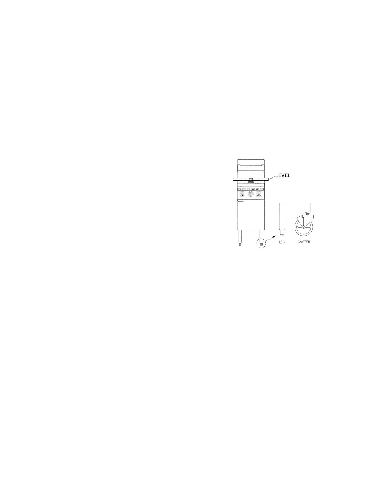
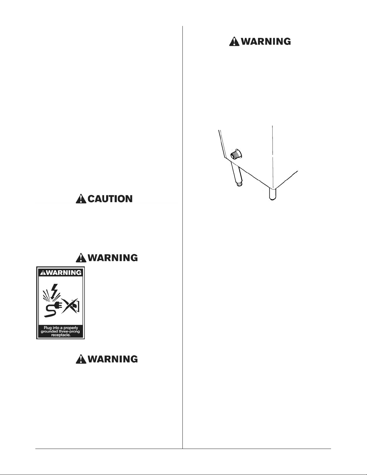
LEVELING
The fryer will operate at its highest efficiency when
properly leveled. Place a level on fryer vessel from side
to side. For fryers on legs, the bottom foot of the leg is
adjustable. Turn clockwise to decrease height or
counter clockwise to increase height until level. For
fryers on casters, the casters are adjustable by
loosening the jam nut and turning the caster in or out.
When the desired level is reached, tighten the jam nut.
Adjustments of more than 3/4" are not recommended
on any caster. The same procedure should be followed
to level the fryer from front to back.
Figure 2-1
RESTRAINING DEVICES
1.) Adequate means must be provided to limit the
movement of the appliance without depending on the
connector and the quick-disconnect device or its|
associated piping to limit the appliance movement.
Fryer must also be restrained to prevent tipping when
installed so that hot liquid splashing is avoided.
2.) The restraint means must be attached to the rear of
the Keating IFM within 2" of the center line width and
approximately 1 5/8" from the bottom of the cabinet
back to allow the restraining bolt to be anchored to the
cabinet back between the cabinet bottom and inner
liner.
IF DISCONNECTION OF THE RESTRAINT IS
NECESSARY, IT MUST BE RECONNECTED WHEN
THE KEATING IFM IS RETURNED TO ITS
ORIGINALLY INSTALLED POSITION.
NOTICE:
WHEN THIS APPLIANCE IS INSTALLED WITH
CASTERS, IT MUST BE INSTALLED WITH CASTERS
SUPPLIED, A CONNECTOR COMPLYING WITH
EITHER ANSI Z21.69 OR CAN/CGA - 6.16 AND A
QUICK-DISCONNECT DEVICE COMPLYING WITH
EITHER ANSI Z21.41 OR CAN1- 6.9. IT MUST ALSO
BE INSTALLED WITH RESTRAINING MEANS TO
GUARD AGAINST TRANSMISSION OF STRAIN TO
THE CONNECTOR, AS SPECIFIED IN THE
APPLIANCE MANUFACTURER’S INSTRUCTIONS.
3
Page 6
INSTALLATION
The installer is responsible for attaching the tipping
restraint.
ELECTRICAL CONNECTION
The Keating IFM, when installed, must be electrically
grounded in accordance with local codes, or in the
absence of local codes, the National Electrical Code,
ANSI/NFPA No. 70. or the Canadian Electrical Code,
CSAC-22.2 as applicable. A wiring diagram is located on
the last page. In the U.S.A. and Canada, the electrical
supply must be 120 VAC, 60 Hz.
The Keating Incredible Frying Machine (IFM) is
equipped with a 9' neoprene covered, 3 wire electrical
cord with a three-pronged grounded plug for protection
against electrical shock. This plug must be placed into
a 120V properly grounded three-pronged polarized
outlet. For proper grounding procedures see local
codes, or in the absence of local codes, the National
Electrical Code ANSI/NFPA 70 (latest edition) or
Canadian Electrical Code CAN 22.2 (latest edition) as
applicable.
Before plugging in the fryer, confirm the outlet is
properly polarized and grounded. If the hot and neutral
terminals are reversed or the outlet is not properly
grounded, the burners may not ignite (burner on light
will go out after 2-1/2 seconds and the ignition
processes will continue 3 times).
THIS APPLIANCE IS EQUIPPED
WITH A THREE-PRONG 120
VOLT NEMA 5-15 (GROUNDING)
PLUG FOR YOUR PROTECTION
AGAINST SHOCK HAZARD AND
SHOULD BE PLUGGED
DIRECTLY INTO A PROPERLY
GROUNDED AND POLARIZED
THREE-PRONG RECEPTACLE.
DO NOT CUT OR REMOVE THE
GROUNDING PRONG FROM
THIS PLUG.
IF DISCONNECTION OF THE RESTRAINT IS
NECESSARY, IT MUST BE RECONNECTED WHEN
THE FRYER IS RETURNED TO ITS ORIGINALLY
INSTALLED POSITION.
GAS CONNECTION
• PIPE JOINT COMPOUNDS RESISTANT TO
PROPANE GASES MUST BE USED.
• BEFORE OPERATING THIS FRYER, CHECK PIPE
JOINTS FOR LEAKS BY USING A SOAP AND
WATER SOLUTION ONLY. DO NOT USE AN
OPEN FLAME!
Figure 2-3
Main Gas Connection
Connect the fryer to the main gas supply line at the rear
of the fryer. The piping should be a minimum of 3/4"
NPT supply pipe for a single fryer at the burner manifold. Batteries require larger supply lines. Installation
must conform to the current local codes and National
Fuel Gas Code (U.S.) ANSI Z223. 1/NFPA 54 (latest
edition), Natural Gas Installation Code
CAN/CGA-B149.1 or Propane Installation Code
CAN/CGA-B149.2 (latest edition).
NOTE: If more than one gas fryer is on the same
supply line, you may require a larger line. Consult your
local gas company to assure adequate volume and
pressure. Refer to serial plate for proper gas
requirements for your particular model.
NOTE: Piping for a battery should be at least 1 1/4” to
1 1/2” IPS, depending on total BTU input. Consult your
local gas supplier for appropriate battery piping size.
NOTE: The electrical wiring diagram for the fryer is
located on the inside of the fryer door or in the back of
this manual.
GAS LEAK TESTING
Prior to lighting your fryer:
1. Make sure all thermostats, switches and safety
valves are in the “OFF” position.
2. Turn main On/Off manual gas valve to the “ON”
position.
3. Have your plumber or gas company check for leaks
with a soap solution. (NEVER check with an open
flame!)
4
Page 7
GAS PRESSURE AT MANIFOLD
NATURAL Gas - 3.0 in. W.C.
LP Gas - 10.0 in. W.C.
MAXIMUM INCOMING GAS PRESSURE
NATUARAL Gas - 7.0 in. W.C.
LP Gas - 11.0 in. W.C.
NOTE: It is estimated that half of all service calls made
on Keating Incredible Frying Machine® (IFM) result
from an inadequate gas supply. During installation,
have a gas company representative make certain that
the fryer is receiving adequate gas pressure and
volume (see “Installation” or your serial plate on the
fryer door).
PROPANE GAS MAY EVENTUALLY LOSE ITS
ODOR AND PRECAUTIONS SHOULD BE TAKEN TO
ASSURE THAT IT IS NOT PRESENT EVEN THOUGH
YOU DO NOT DETECT AN ODOR. IF THERE IS ANY
DOUBT, YOU SHOULD CALL YOUR LOCAL
PROPANE GAS SUPPLIER FOR ASSISTANCE.
OPERATING
FILLING
NOTE: Before filling the fryer make certain the fryer
vessel is sanitized, dry and the drain valve is
completely closed. Refer to item 13 on page 16, or item
11 on page 18 for location of drain valve.
NOTE: We recommend that solid shortening not be
used in an Incredible Frying Machine (IFM) as they are
not equipped with a melt cycle. If solid shortening is
used, it should be melted prior to filling the fryer vessel.
Damage done by melting solid shortening in the fryer
vessel will void the warranty.
BE SURE THE HEAT TRANSFER TUBES ARE
COMPLETELY COVERED WITH OIL BEFORE
SWITCHING THE FRYER ON. IF OIL LEVEL DROPS
BELOW TOP OF HEAT TRANSFER TUBES, SEVERE
DAMAGE TO FRYER AND INJURY TO OPERATOR
MAY RESULT.
DO NOT MIX HOT OIL AND WATER IN ANY FORM.
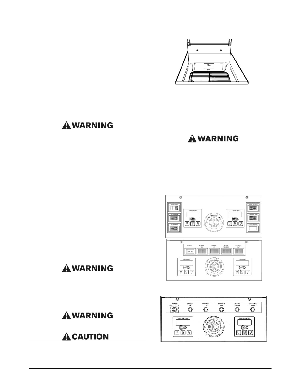
Oil expands when heated. The “Max” line has been
provided to ensure optimum cooking while ensuring the
safety of the operator. Do not overfill the fryer vessel.
See Figure 3-1.
Figure 3-1
“Max” Level Line
Fill the fryer vessel with oil or MELTED solid shortening
up to the “Max” line.
LIGHTING
BEFORE ATTEMPTING TO LIGHT THE FRYER,
MAKE SURE THE GAS CONNECTIONS ARE
SECURE AND HAVE BEEN LEAK TESTED AND
THE FRYER HAS BEEN PROPERLY FILLED WITH
OIL.
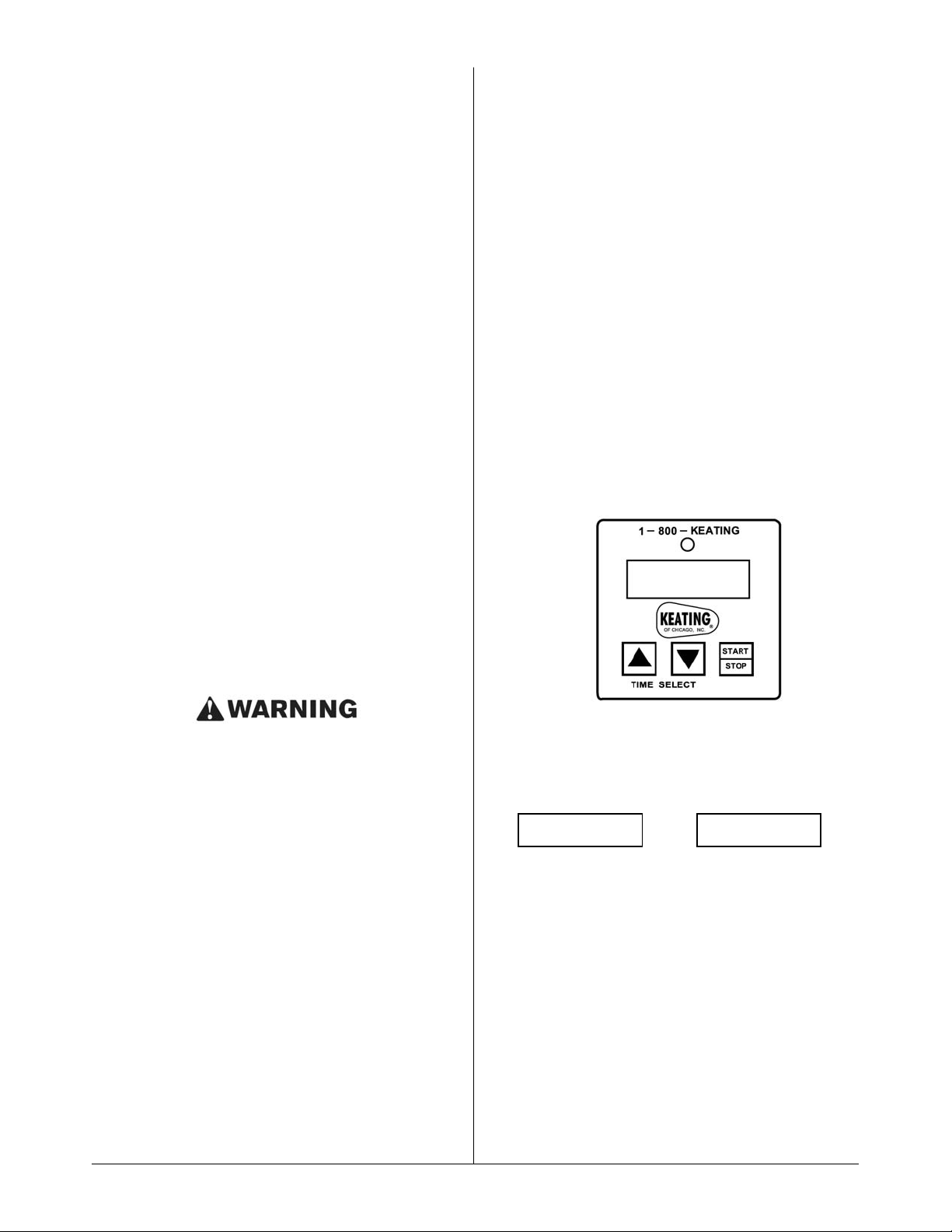
Figure 2-4 IFM Control Panel
Control Panel with timers Model 2000
14” Control Panel with timers Model 2006
5
Page 8
1. Turn on main power switch.
2. Set thermostat to desired setting. (Between
325°F/162.8°C) – (335°F/165.3°C)
3. Once main power switch is on and the thermostat
is set, the following occurs:
a. Blower will start and blower indicating light will
come on.
b. After a preset ten second delay, the gas valve
will open and the burner indicating light will
come on.
c. The spark module will light the burners auto-
matically.
d. The burner indicating light will be on whenever
the burners are on. The light goes off when the
oil has reached the desired temperature. If the
burners do not light immediately, the burner
light will shut off, the blower light will stay on,
and after 6 seconds, the burners will try to light
again. This process will repeat 3 times.
NOTE: The fryer cannot be operated during a power
failure as the electronic ignition system cannot be
operated.
COOKING
Keating Incredible Frying Machine
®
Gas Fryers (IFM)
are designed to provide maximum production
efficiency and deliver high quality food products.
Low- temperature cooking, highly polished stainless
steel and a true COLD ZONE mean extended oil life.
Follow cooking procedures below for your model.
• OPERATION OF THIS FRYER SHOULD BE LIMIT-
ED TO PERSONNEL WHO HAVE BEEN THOROUGHLY TRAINED IN OPERATING PROCEDURES.
• USE ONLY KEATING APPROVED BASKETS IN
YOUR FRYER. NEVER OVERFILL FRY BASKETS.
DO NOT BANG BASKETS ON BASKET HANGERS OR ON FRYER VESSEL.
• CARE SHOULD BE TAKEN WHEN LOWERING
BASKETS INTO FRYER TO PREVENT SPLASHING HOT OIL FROM FRYER VESSEL.
• NEVER LIFT BASKETS DIRECTLY OUT OF THE
FRYER VESSEL WITHOUT DRAINING, AS
SEVERE INJURY MAY RESULT.
1. Set thermostat to the desired frying temperature
(between 325°F - 335°F).
2. When the oil reaches the desired temperature,
burner indicating light will go off.
3. Set timer(s) to desired cooking time and fill basket(s) to proper level (if applicable).
4. Lower filled basket(s) slowly into oil. For fryers with
automatic basket lift, place basket(s) on upper basket hanger rods on splashback of fryer.
5. Push “T1”, “T2” or “T3” button of electronic timer(s).
This simultaneously activates the Instant-On™
systems (if applicable). For fryers with automatic
basket lift, basket(s) will lower into fryer vessel.
6. When timer(s) sounds, carefully lift basket(s) out of
hot oil (if applicable). For fryers with automatic basket lift, a buzzer will sound and the basket(s) will
rise automatically. Allow oil to drain before removing.
7. Place basket(s) on basket hanger rods on splashback of fryer and allow to drain.
SHUT DOWN
Turn off main power switch.
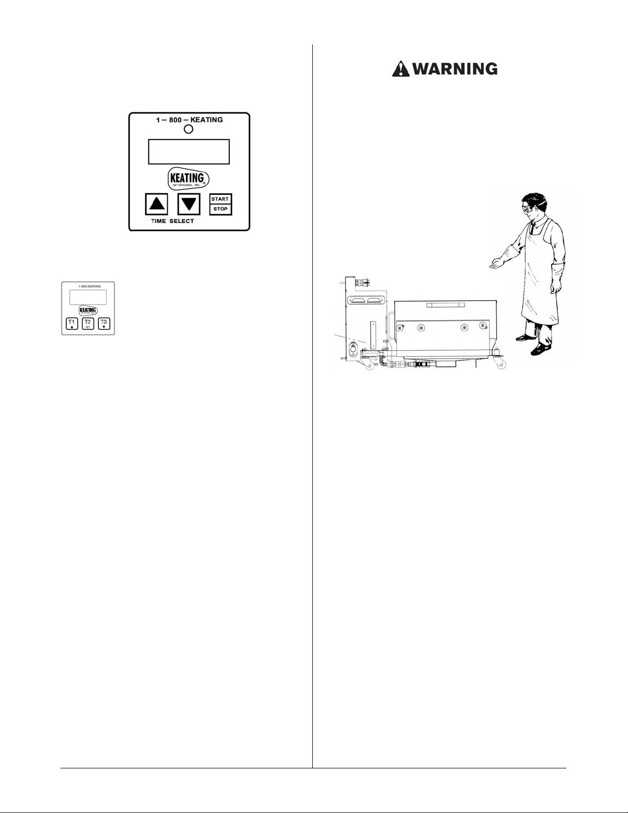
DIGITAL TIMER (PART # 030834)
RESETTING TO MINUTES : SECONDS
STEP 1
Make certain power to the timer has been OFF for at
least 30 seconds. Then PRESS and hold down the UP
arrow button while turning the rocker power switch to
the ON position. The timer will turn ON and the display
will now be indicating
OR
The BEEPER will BEEP 4 times.
If STEP 1 was OK, proceed to STEP 2. If not, retry Step
1 making sure the power was OFF for at least 30
seconds or more.
6
– – – – – –:– –
Page 9
STEP 2 PRESS all 3 buttons in sequence: left-center-
right. The BEEPER will BEEP. If BEEPER
does not BEEP, the timer is defective. STOP
TESTING. Reset procedure is completed
when 1:00 appears on the digital display.
DIGITAL TIMER (PART # 030834)
PROGRAMMING
To program the timers, the unit must be in
the idle mode. Press and hold the set button for approximately two seconds. The
display will show “SEt”. Press the button
for the channel to be programmed. The
display will show the current setting for that channel.
Use the up or down button to increment or decrement
the setting. When the setting is correct, press and hold
the set button again for approximately two seconds.
The display will show "StO" for approximately two seconds and the timer will return to normal operation.
Repeat the process as necessary for the other timers.
OPERATING LOGIC
When the timer is powered up, the display will show the
time setting for the channel that was operated last and
the relay output contacts will be open. To start a cycle,
press the desired channel button (1-3). The display will
begin to countdown from the preset time setting and
the relay output contacts will close. During the
countdown the colon will flash at a one-second rate.
When the countdown has reached "00:00" the relay
output contacts will open, the display will flash, and the
audible alarm will sound. To cancel the audible alarm,
press any button.
PAUSE FEATURE
To pause a cycle in progress, press any button. The
relay output contacts will open, the display will flash,
and the countdown will pause. To resume the
countdown, press any button. The display will resume
the normal countdown and the relay output contacts
will close.
CANCELING A CYCLE
To cancel a cycle in progress press and hold any
button for approximately two seconds. The relay output
contacts will open and the display will show the time
setting for the channel last used.
DRAINING
ALWAYS SHUT THE FRYER OFF COMPLETELY
BEFORE DRAINING. THE FRYER SHOULD BE
DRAINED ONLY UNDER THE SUPERVISION OF
PROPERLY TRAINED PERSONNEL. A DRAIN PIPE
AND COVERED CONTAINER SUITABLE FOR USE
WITH HOT OIL SHOULD BE USED TO ENSURE THE
SAFETY OF THE OPERATOR.
1. Operator should be outfitted with proper attire
including:
–Oil and heat resistant gloves
–Oil and heat resistant apron
–Safety goggles
–Oil and heat resistant footwear
Figure 3-2
2. Turn off the fryer and open the door.
3. Put suitable container under drain valve (for Safe &
Easy models, slide filter onto rails inside of fryer or
filter cabinet).
4. • Front Drain: Drain oil from fryer by slowly
turning handle. The drain will be completely
open after 1/4 turn.
• Rear Drain: Pull black knob forward slowly.
5. After fryer drains, close the drain valve.
6. Filtering may be done at this step - refer to filter
manual.
CLEANING AND BOIL-OUT
When cleaning and boiling out your fryer use Keating
Sea Powder and Keating Klenzer to keep your fryer in
top condition. Keating Sea Powder dissolves any grease
build up — even carbonized grease in fryer vessels —
one of the leading causes of premature oil breakdown.
Once your fryer vessel is clean, use Keating Klenzer, the
finest dry stainless steel polish available, to restore your
Keating Incredible Frying Machine
®
’s (IFM) exterior to its
original luster.
7
11:: 0000
Side view of Safe & Easy Filter
Page 10
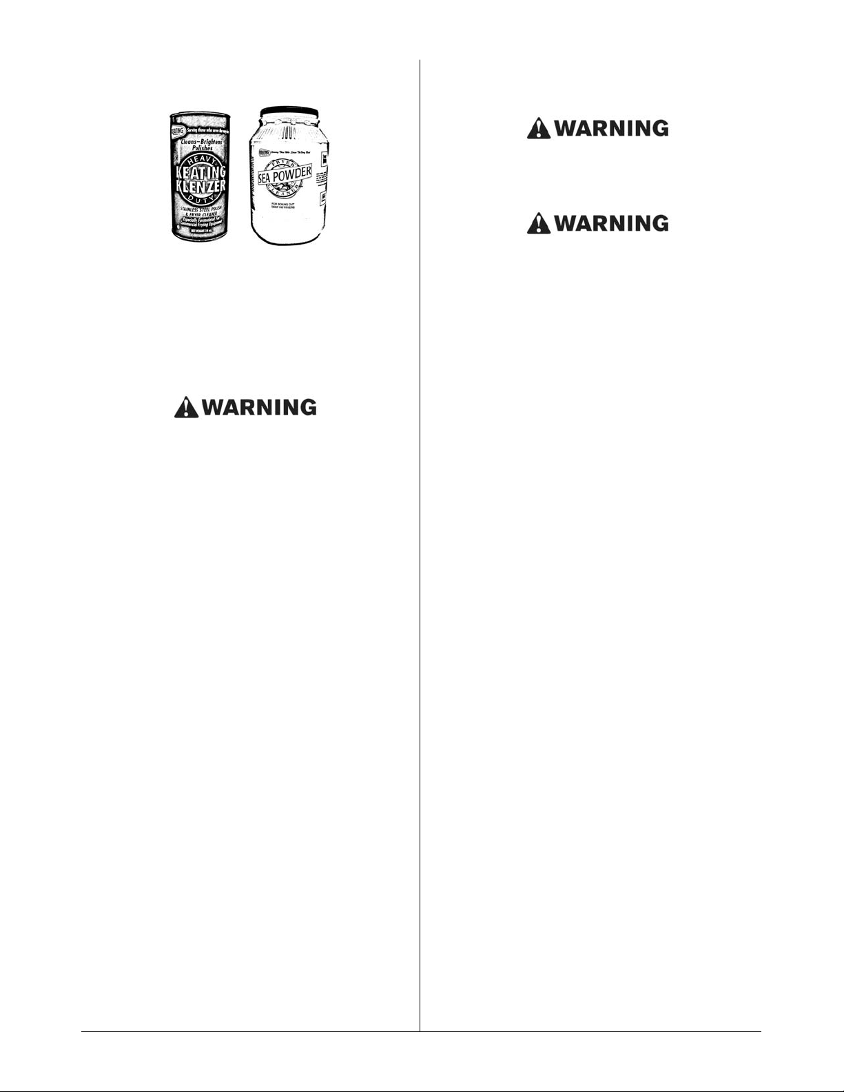
Figure 3-4
Keating Klenzer and Sea Powder
1. Put on safety attire. See Draining.
2. Turn the fryer off
3. Drain oil from fryer, see draining steps 2-4 above.
4. Remove oil container to a secure area to prevent
accidental spillage.
5. Fill fryer vessel to “Max” line with water.
UNDER NO CIRCUMSTANCES SHOULD THE
FRYER BE LEFT UNATTENDED DURING BOIL-OUT.
TRAINED PERSONNEL MUST BE PRESENT
DURING THE PROCEDURE TO PREVENT BOIL
OVER OR TO TURN OFF THE POWER IF WATER
DROPS BELOW HEAT TRANSFER TUBES.
6. Set thermostat and turn fryer on to bring water to a
gentle boil.
7. Once boil has been reached, turn fryer off.
8. Dissolve
2
/
3 cup of Keating Sea Powder for every
five gallons of water and let soak for
1
/2
hour. If there
is a large build-up of carbonized grease, allow fryer
to soak overnight.
CAUTION: When soaking overnight, make sure the
fyer is turned off.
CAUTION: Do not damage or reposition thermostat
probe as this may affect the accuracy of the fryer.
9. While soaking, a natural fiber brush may be used
to scrub the tubes and inside walls of fryer.
10. Drain the water and Sea Powder into a dry suitable
receptacle and remove from cooking area.
NOTE: DO NOT pump water through the filter
machine.
11. Spread Keating Klenzer liberally on tubes and
sides of fryer vessel.
12. A non-abrasive scouring pad may be used to
remove the now softened carbonized grease.
13. Thoroughly rinse fryer vessel with potable water to
remove all Klenzer.
14. Prior to refilling with oil, wipe the inside of the fryer
vessel making sure all water and Klenzer has been
removed.
DO NOT MIX HOT OIL AND WATER IN ANY FORM.
15. Close drain valve.
FAILURE TO CLOSE DRAIN VALVE BEFORE
REFILLING THE FRYER MAY RESULT IN SERIOUS
INJURY.
16. Check thermostat bulb positioning – see page 9.
17. Refill the fryer with new oil.
8
Page 11
MAINTENANCE
WARRANTY REPAIRS
Keating’s warranty begins with the date of installation
(or ship date if we are not notified of an installation
date).
In the event that your fryer, under warranty, needs
repairs other than routine maintenance or cleaning,
you are required to contact Keating of Chicago
(at 1-800-KEATING) before calling a local service
company. Failure to do so may void your warranty.
PREVENTIVE MAINTENANCE
Preventive maintenance should be done in daily, weekly, monthly and yearly intervals as necessary. Following
preventive maintenance procedures will help keep your
fryer working efficiently. Proper care and servicing will
lead to years of quality performance.
A. Oil Breakdown
As part of a “Preventive Maintenance Program”, the oil
in your fryer needs to be filtered regularly to avoid
breakdown. The initial investment in the frying system
is less than the total overall costs of oil during the life of
the fryer, and with regular filtering, you can realize substantial savings in oil costs, as well as maintenance
charges.
B. Thermostat Calibration
You will need:
One screwdriver with 1/8" wide flat blade
One accurate fryer thermometer
1. Set thermostat to desired frying temperature.
2. Allow fryer to cycle three times.
3. Place an accurate thermometer in the oil at the tip
of the thermostat bulb.
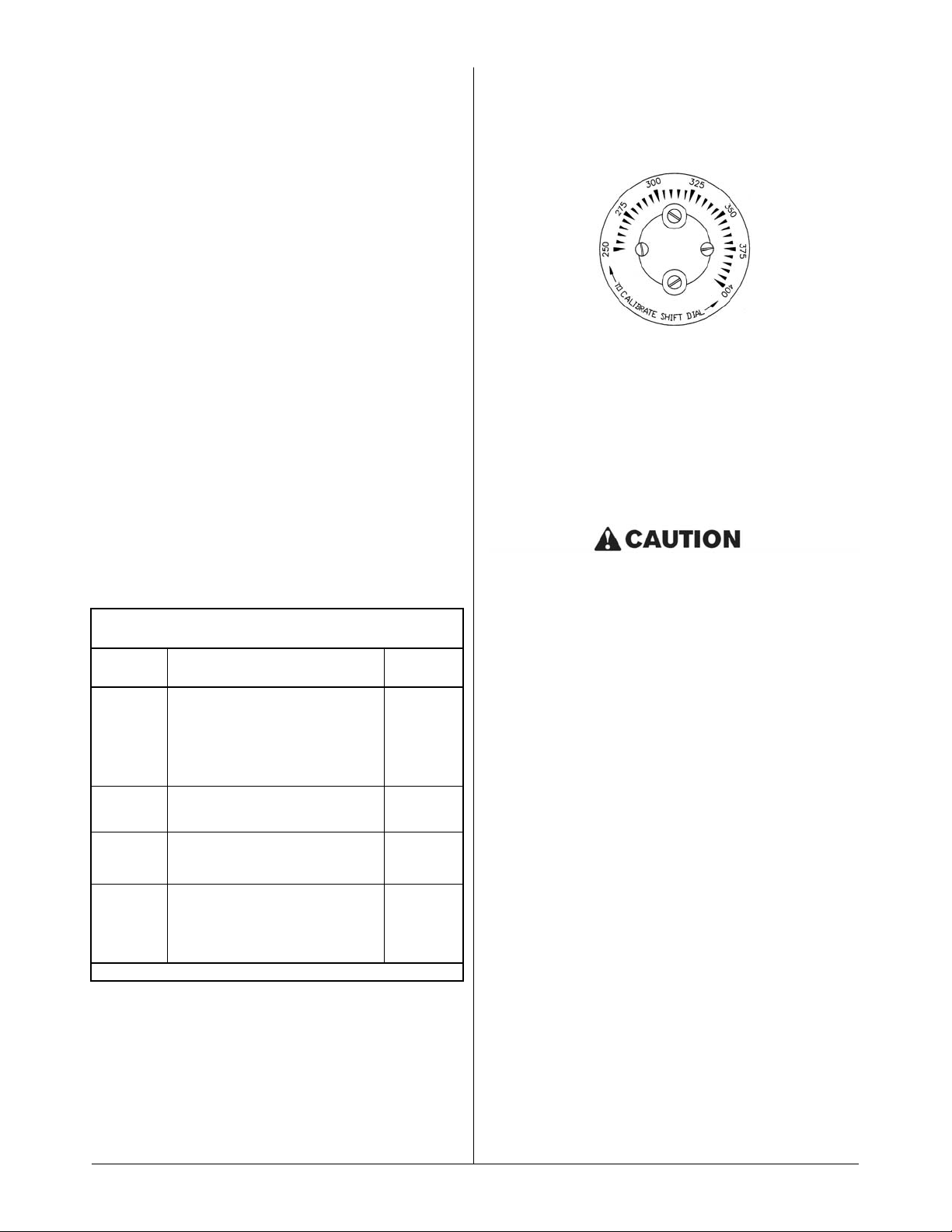
Figure 4-1
Dial Plate with knob removed
NOTE: Locate thermometer in same position for every
calibration.
4. If calibration of fryer is found to be less than 25°F
off, simply loosen the four retaining screws holding
the dial plate in place. Reset the dial plate to match
the thermometer reading. If the fryer is found to be
more than 25°F off, a qualified service company
must be contacted to have the fryer properly
calibrated.
Do NOT adjust set screw on thermostat.
C. Thermostat Bulb Positioning
BEFORE REPLACING, TEST THERMOSTATS:
Operational problems can easily be corrected by
thermostat bulb positioning.
Keating’s patented thermostat application is accurate
within 2°F of the dial setting between 250°F – 350°F.
This accuracy is attained only if the thermostat bulb is
placed properly against the heat transfer tube. To
quickly and accurately test for proper bulb placement,
a single thickness of writing paper should be pulled
through between the tube and the bulb with medium
resistance.*
1. *For gas fryers 14":
• The end of thermostat bulb should touch the burner tube.
2. For gas fryers 18" & up:
• If the bulb is too loose, the paper will slip through
with little or no resistance. A fryer with a thermostat bulb that is too loose will overshoot.
Overshoot: The thermostat takes a long time to
cycle and then misses its preset temperature by
20°F - 40°F yielding a poor quality product.
• If the bulb is too tight, the paper will either not pull
through or it will tear. A fryer with a thermostat
bulb that is too tight will short cycle.
9
PREVENTIVE MAINTENANCE CHART
TIME
FRAME
OPERATOR/OWNER SECTION
Daily*
• Check lights and controls
• Check that the oil is up to
“Max” line.
• Clean all baskets
• Drain, strain or filter shortening.
III
Weekly*
• Drain and clean fryer
• Boil-out fryer
III & VI
Monthly*
• Verify thermostat settings.
• Test Hi-Limit control.
III
IV & V
Yearly*
QUALIFIED SERVICE PERSONNEL ONLY
• Check burner flame color and
adjust air shutters.
V
* High production facilities should be checked more often.
Page 12
Short Cycle: The thermostat will cycle rapidly while
the fryer is in the idle mode; the temperature will be
erratic.
Thermostat Bulb Positioning 18
" & up Fryer Gas
SERVICE
ALL HI-LIMIT CONTROLS ARE PRESET AT THE
FACTORY FOR A SPECIFIC TEMPERATURE. DO
NOT
ATTEMPT TO CHANGE THE SETTING OF THE
HI-LIMIT. IF THE HI-LIMIT FAILS TO SHUT OFF
BETWEEN 425°F AND 450°F DURING TESTING, IT
MUST BE REPLACED.
FLAME ADJUSTMENT
A. Gas Pressure
1. At gas valve, remove adjustment port cover, rotate
adjustment screw with screwdriver and replace
port cover.
2. To check the gas pressure (3" WC for natural gas
or 10" WC for Propane at the manifold), use an
allen wrench to remove the gas pressure test port,
located in the center of the manifold.
3. Line pressure (incoming pressure) is critical for
proper ignition of the IFM. Incoming pressure must
be : Natural - 7” W.C.
Propane - 11” W.C.
B. Air Flow
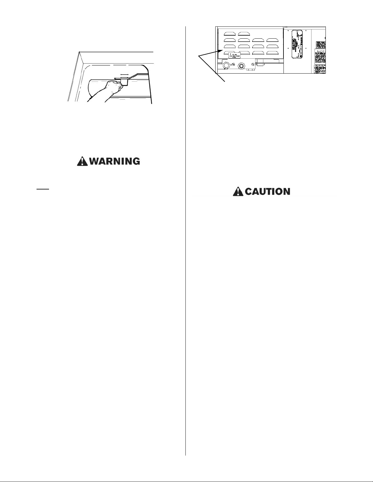
1. To determine the proper gas/air mixture, look into
the viewing window for each burner, located just to
the left of each burner air hose where the hose is
connected to the burner assembly. (See figure
below).
• bright red/orange with proper mixture – orange
“glow” around burner tube
• too much gas – orange “haze” around burner
tube (showing incomplete combustion)
• too little gas – blue at front of burner, or totally
blue
REQUIRED TEST THERMOSTAT
Multimeter (for testing continuity)
CHECKING CONTINUITY WITH THE MULTIMETER
1. Rotate the thermostat shaft until an audible click is
heard.
2. Rotate the thermostat shaft left and right ten times
causing the switch to click on and off ten times,
while using the Multimeter to verify continuity.
3. If the switch does not show continuity during all
ten trials, replace the thermostat.
Disassembling the thermostat will void the
thermostat warranty.
1. Set compression ring onto capillary end of bulb
finger tight, 1/2” from end of capillary.
2. Insert new thermostat bulb through control panel
back.
3. Apply oil resistant flexible sealant ontocompression
fitting thread before installing fitting into fryer
vessel.
4. Position bent portion of bulb against far right heat
transfer tube and install compression fitting snugly
into fryer vessel.
5. Adjust bulb so at least 2” of bent portion of it is next
to heat transfer tube and tighten compression nut
onto compression fitting for fryer 18 & up. The end
of thermostat bulb should touch the burner tube for
14" fryers.
6. Refill fryer with oil to “fill level line”.
7. Start fryer, preheat and calibrate with
thermometer.
SERVICE DIAGNOSIS
A properly adjusted Keating Incredible Frying
Machine® (IFM), with no load, will cycle “On”
approximately every 2 1/2 to 3 minutes. Each cycle will
last 15 to 25 seconds, ensuring that the temperature
setting is held within a narrow band.
• Every Keating Incredible Frying Machine®
(IFM) has a number of safety controls to
ensure safe operation and guard against
component failure.
10
Remove the cover by loosening the screws to gain access to the
burner viewing windows (14” Model Shown).
Page 13

SELF-HELP GUIDE
11
Common Problems Probable Cause Solutions (Follow Sequentially)
1. No power to unit.
a. Power switch light ON only.
b. Power Switch light and Red
overmax temperature light on.
c. All lights are off.
a. Drain handle not locked into
place.
b. High limit light has tripped.
c. Breaker has tripped.
a. Locate the handle used to drain
oil from fryer. Pull handle up and
push it in as far as possible,
locking it into place and
activating the safety switch.
b. Reset the high-limit (press the
red button located in the bottom
of the control panel).
c. Reset the breaker located on the
bottom of the control panel,
check the outlet or check the
breaker at the wall.
2. Timers (or lights) ON but fryer
does not try to light.
a. Thermostat off. a.Set the thermostat to desired
temperature.
3. Blower light on. Red burner light
comes on and goes out after
about 3 seconds.
a. Problem with the outlet at the
wall.
b. Gas not turned on or not hooked
up.
a.Plug fryer in to a different
electrical outlet (must be properly
grounded).
b.Ensure gas hose is securely
connected. Turn on main gas.
4. Not recovering. a. Gas pressure incorrect.
b. Thermostat not calibrated.
c. Overloading fryer.
a.Contact service agent to verify
proper gas pressure.
b.Calibrate the thermostat by
rotating the dial plate to match the
actual temperature of the oil (See
page 9).
c. Do not overfill baskets with food.
d.Do not overfill fryer with oil (check
the fill level stamped into the fry
pot).
Page 14

12
Problem Probable Cause Solution
Main power light does not come on. a.Fryer not plugged in.
b.Breaker has tripped.
c. Main power switch is faulty.
a.Plug fryer into approved outlet. Must
be properly grounded.
b.Reset the breaker lcoated on the
bottom of the control panel
c. Replace the main power switch.
Blower light does not come on. a.Thermostat not turned on.
b.If blower comes on, blower light is
faulty.
c. If Over Maximum Temperature light is
on, Hi-Limit has been activated.
d.If unit has a filter, drain handle not
locked into place.
a.Set thermostat to desired
temperature.
b.Replace blower light.
c. Reset Hi-Limit after oil has cooled
down below 425°F. Correct problem
which caused Hi-Limit to activate
(See page 10).
d.Secure drain handle in place
behind the bracket.
Burner light does not come on. • Check for flame at each burner. If
no flame is present at either burner:
a.Spark module is faulty.
• Check for flame at each burner. If
flame is present at both burners:
b.Burner light is faulty.
a.Replace spark module.
b.Replace burner light.
Burner light comes on, then goes
out (after 2 1/2 seconds).
• Check for spark at each burner. If
no spark at either burner:
a.Spark electrode wires are not tight or
faulty.
b.Spark electrode is faulty or is out
of alignment.
• Check for spark at each burner. If
spark occurs at both burners:
c. Gas is not hooked up properly or
not turned on.
d.Spark electrode is faulty or is out
of alignment.
e.Combination gas valve is faulty.
a.Tighten spark electrode wires or
replace.
b.See detail on page 26.
c. Turn manual gas valve on. If using
flexible connector with quick
disconnect, make sure that the quick
disconnect is completely engaged.
d.Align spark electrode. Replace spark
electrode if faulty. Gap must be 1/8"
between electrode and pilot tube and
between pilot tube and burner (See
page 26).
e.Replace combination gas valve after
verifying it has voltage.
TROUBLESHOOTING CHART
The following diagnosis is only to be used as a guide to qualified service personnel. Keating recommends that you
use a qualified service company. Call 1-800-KEATING if you need assistance in locating a qualified service
company.
NOTE: To correctly and quickly diagnose the system, the chart below must be followed in sequential order.
Page 15

13
Problem Probable Cause Solution
Delayed ignition. a.Spark electrode gap is incorrect.
b.Gas pressure excessive (incoming or
manifold).
c. Spark module intermittent.
a.Set proper gap on electrode (See
detail on Page 26).
b.Set pressure to serial plate.
c. Replace spark module.
Fryer has poor recovery. a.Over-filling baskets.
b.Over-filling fryer with oil.
c. Thermostat bulb improperly placed.
d.Carbon coating on heat transfer
tubes.
e.Low gas pressure or volume.
f. Inefficient burner combustion.
a.Don't over-fill baskets.
b.Fill fryer up to “Fill Level” line as oil
will expand when heated.
c. Adjust bulb position. See page 9 –
Thermostat Bulb Positioning.
d.Boil-out fryer. See page 7 –
Cleaning and Boil-out.
e.Contact a qualified service person
to check gas pressure.
f. Adjust gas/air mixture. See page 10
– Flame Adjustment.
Fryer overshoots temperature
setting.
a.Thermostat bulb improperly placed.
b.Thermostat out of calibration.
a.Adjust bulb position. See page 9 –
Thermostat Bulb Positioning.
b.Calibrate thermostat. See page 9 –
Calibration.
Oil in fryer vessel smokes. a.Oil has begun to break down.
b.High carbon content in oil.
c. Dirty fryer vessel.
d.Inferior grade of oil.
e.Fryer is overheating.
a.Replace oil.
b.Filter oil completely, replace if
necessary.
c. Boil-out fryer. See page 7 – Cleaning
and Boil-out.
d.Check with supplier for the grade of
oil you need for your cooking
applications.
e.Check calibration of thermostat (See
page 9) and replace if necessary.
Basket lift mechanism will not operate.
a.Breaker tripped.
b.Connections are loose or electronic
timer is faulty.
c. Actuator defective.
a.Reset breaker located in rear of fryer.
or on bottom of control panel back
(Note Basket Lift circuit breaker is
labeled).
b.Make sure connections are tight.
Replace timer if faulty.
c. Replace actuator.
Page 16

14
Problem Probable Cause Solution
Basket-lift motor runs, but basket
does not move.
a. Actuator is faulty. a. Replace actuator.
Basket(s) rise prematurely. a. Electronic timer is faulty.
b. Basket lift relay is faulty.
a. Replace timer.
b. Replace relay.
Spark module flashing. a. Steady OFF.
b. Steady ON.
c. 1 Flash.
d. 2 Flashes.
e. 3 Flashes.
f. 4 Flashers.
g. 5 Flashes.
a. NO Power or Control Hardware
Fault.
b. Power Applied; Control Okay.
c. No flame sense (current trial
only). Active until flame sense on
next trial.
d. Marginal flame between 1.5mkA
and 0.5mkA.
e. Ignition lockout; too many ignition
failures:
1. Turn off unit.
2. Check incoming gas.
3. Spark at electrode.
4. Electrode.
f. Ignition lockout; too many flame
losses:
1. Turn off unit.
2. Check incoming gas.
3. Spark at electrode.
4. Electrode.
g. Control hardware fault detected.
Page 17

ITEM MODEL PART NO. DESCRIPTION QTY
1 14” 030862 Blower 1
18” & 20” 053726 Blower 1
052471 Insulation 2
2 054162 Air Hose 2
015393
1
/2" Clamp 2
3 Call 1-800-KEATING Fry Pot 1
4 020717 Pilot Tee 1
5 022031 Pilot Tubing 1/8 S/S 2
6 016231 Elbow Brass 90° 2
015390 Bushing 2
14” 016502 Orifice #29 2
18” & 20” 021869 Orifice #18 2
7 054512 Flexible Main Tubing 2
054426 Flexible Main Tubing Elbow 2
8 054208 Flexible Pilot Tubing 2
9 053777 Magnetic Reed Switch 1
10 052572 Nipple Quick Connect 1
053445 Rubber Grommet 1
11 031532 Knob Drain Handle 2
12 024030 Gas Valve Nat 1
024988 LP 1
13 14” 016341 Drain Valve 1" Rear 1
18” & 20” 016342 Drain Valve 1
1
/4"Rear 1
14 ALL Drain Valve Pull Rod Assembly
053650 Drain Valve Handle Rod 1
011138 Drain Valve Adjustment Sleeve 1
053649 Drain Valve Handle 1
052653 Drain Valve Pull Rod 1
15 054428 Fitting 5/8 cc x 1/2"1
16 054419 Hex Reducing Nipple 1
17 000611 Check Valve 2-way 1
18 007260 Fitting Compression Elbow 1
19 037537 Caster swivel, locking 2
20 037539 Caster, rigid 2
15
PARTS LIST
ORDERING PARTS
Parts may be ordered by part number by calling your local service company or Keating at 1-800-KEATING. You
may also order on-line at Keating’s part store, www.keatingofchicago.com.
Refer to the Keating Incredible Frying Machine® Limited Warranty for complete service and ordering information.
The model/serial plate is located on the inside of the front door. The serial and model numbers are necessary when
ordering.
WARNING AND OPERATING PLATES
All warning and operating plates on the Keating Incredible Frying Machine® should be in place at all times. If plates
are damaged or lost, replace them immediately.
INCREDIBLE FRYING MACHINE® GAS FRYER PARTS LIST - MODEL 2000
Page 18
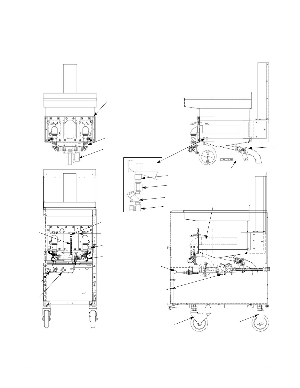
Oil Return Piping
Assembly
(Enlarged View)
Front View
Side View
3
2
1
8
9*
4
5
10
7
6
15
16
17
18
13
14
Burner & Electrode Assembly
See Detail on Page 23
12
11
19
20
16
INCREDIBLE FRYING MACHINE® GAS FRYER
REAR DRAIN - MODEL 2000
(corresponds with parts list on page 15)
* Not shown
See pages 20-22 for Control Panel Parts List.
Page 19

17
INCREDIBLE FRYING MACHINE® GAS FRYER PARTS LIST - MODEL 2006
ITEM MODEL PART NO. DESCRIPTION QTY
1 14” 030862 Blower 1
18” & 20” 053726 Blower 1
2 ALL 057996 Air Hose 1.25" ID 9" long 2
ALL 015393 Clamp 1/2" wide band 13/16 × 1 1/2" 2
3 Call 1-800-KEATING Fry Pot 1
4 ALL 006474 Pilot Tee
5 ALL 037549 Tubing S/S 3/16" × 1" 2
6 ALL 054205 Flex tubing 1/4" S/S 6" Long 1
7 ALL 037543 Fitting Compression 1/4" – 3/16 Reduction 2
8 ALL 054208 Flex tubing 1/4" S/S 15" Long 1
9 ALL 054512 Flex tubing 3/8" S/S 6" Long 2
ALL 054426 Compression 3/8 × 1/8 90° Elbow 2
ALL 015331 Tape 1/2" × .520 Teflon A/R
10 ALL 024030 Gas Valve - Natural Gas 1
ALL 024988 Gas Valve - LP 1
11 14” 004553 Drain Valve 1" Front 1
18” & 20” 004554 Drain Valve 1 1/4" Front 1
12 ALL 037537 Caster - Swivel, Locking 2
13 ALL 037539 Caster - Rigid 2
Page 20
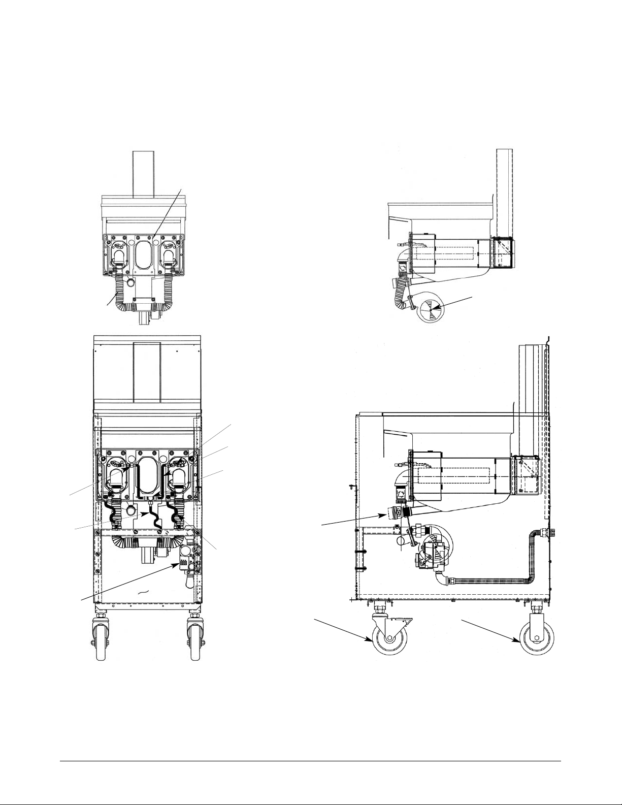
18
INCREDIBLE FRYING MACHINE® GAS FRYER
FRONT DRAIN - MODEL 2006
(corresponds with parts list on page 17)
See pages 23-25 for Control Panel Parts List.
Front View
Side View
2
5
6
4
9
11
12
7
8
10
3
1
13
Page 21
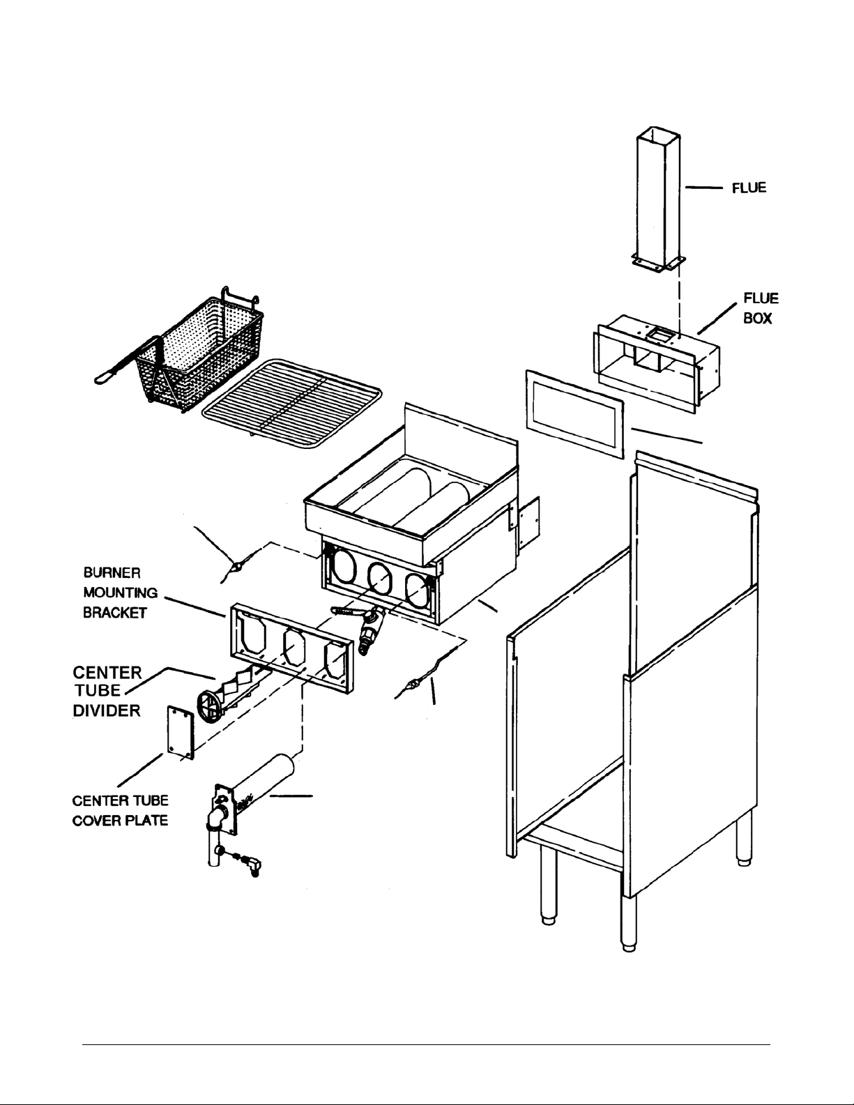
19
INCREDIBLE FRYING MACHINE® (IFM) GAS FRYER ASSEMBLY FRONT DRAIN
(FOR REFERENCE ONLY)
HIGH LIMIT
THERMOSTAT
FRY POT (FRONT
DRAIN SHOWN)
BURNER
ASSEMBLY
(SEE PAGE 17)
INSULATION
Page 22
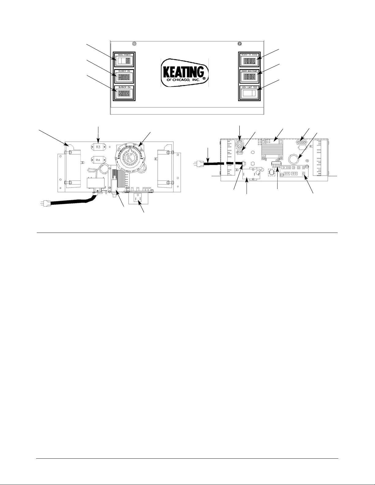
ITEM DESCRIPTION QTY PART NUMBER
1 Power Switch with green Light 1 032242
Power Switch without Light 1 035030
2 Indicating Light Blue 1 015120
3 Indicating Light Amber 1 021254
4 Indicating Light Green 1 021255
5 Indicating Light Red 1 021209
6* High Limit Test Switch (Momentary) 1 015384
7 Spark Ignition Module 2 037550
Spark Ignition Cable (Not Shown) 2 037551
8 Relay DPDT 24VAC 2 030844
9 Thermostat - 14” Model 1 035574
Thermostat - 18” & 20” Models 1 035575
Thermostat Dial Plate 1 058037
Thermostat Knob 1 004163
10 Circuit Breaker 1 053338
11* Receptacle Snap-In 125 VAC 1 011505
12 6 Circuit Quick Connect Female 1 028301
Female Pins 6 028308
13 2 Circuit Quick Connect Female 1 032207
Female Pins 6 028308
14 Transformer 120V-24V 1 024032
15 4 Circuit Quick Connect Female 1 032211
Female Pins 6 028308
16 Snap-In Bushing 1” 3 005664
17 Terminal Board with Insulation 1 004153
18 12 Circuit Quick Connect Male 1 028306
Male Pins 10 028309
19 High Limit (Resettable) 1 034357
20 Strain Relief Bushing 1 000430
21 Power Cord 120V 9ft. 1 006311
*Not available on all models
20
IFM CONTROL PANEL PARTS LIST (CONCEALED THERMOSTAT - NO TIMERS) MODEL 2000
1
2
3
4
5
6
7
8
9
10
11
12
13
14
15
16
17
18
19
20
21
Back Panel (Front View)
Back Panel (Top View)
Page 23
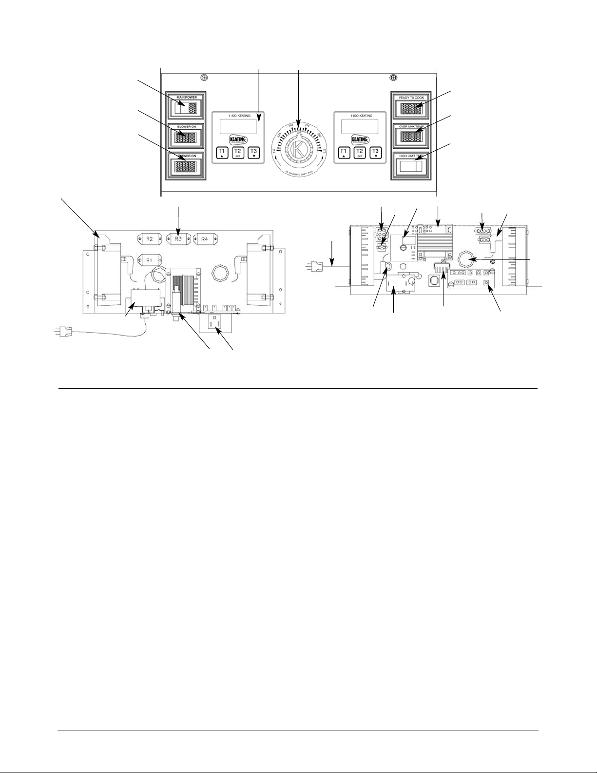
ITEM DESCRIPTION QTY PART NUMBER
1 Power Switch with green Light 1 032242
Power Switch without Light 1 035030
2 Indicating Light Blue 1 015120
3 Indicating Light Amber 1 021254
4 Indicating Light Green 1 021255
5 Indicating Light Red 1 021209
6* High Limit Test Switch (Momentary) 1 015384
7 Spark Ignition Module 2 037550
8 Relay DPDT 24VAC 3 030844
9 Thermostat - 14” Model 1 035574
Thermostat - 18” & 20” Models 1 035575
Thermostat Dial Plate 1 058037
Thermostat Knob 1 004163
10 Circuit Breaker 1 053338
11* Receptacle Snap-In 125 VAC 1 011505
12 6 Circuit Quick Connect Female 1 028301
Female Pins 6 028308
13 2 Circuit Quick Connect Female 1 032207
Female Pins 6 028308
14 Transformer 120V-24V 1 024032
15 4 Circuit Quick Connect Female 1 032211
Female Pins 6 028308
16 Snap-In Bushing 1” 3 005664
17 Terminal Board with Insulation 1 004153
18 12 Circuit Quick Connect Male 1 028306
Male Pins 10 028309
19 High Limit (Resettable) 1 032243
20 Strain Relief Bushing 1 000430
21 Power Cord 120V 9ft. 1 006311
22 Timer 2 056921
23 Spark Ignition Cables 2 037551
24 Relay 35 Seconds 1 030845
*Not available on all models
21
IFM CONTROL PANEL PARTS LIST (WITH TIMERS) MODEL 2000
1
2
3
4
5
6
7
8
10
11
12
13
14
15
16
17
18
19
20
21
Back Panel (Front View)
Back Panel (Top View)
22
9
19
24
23
Page 24
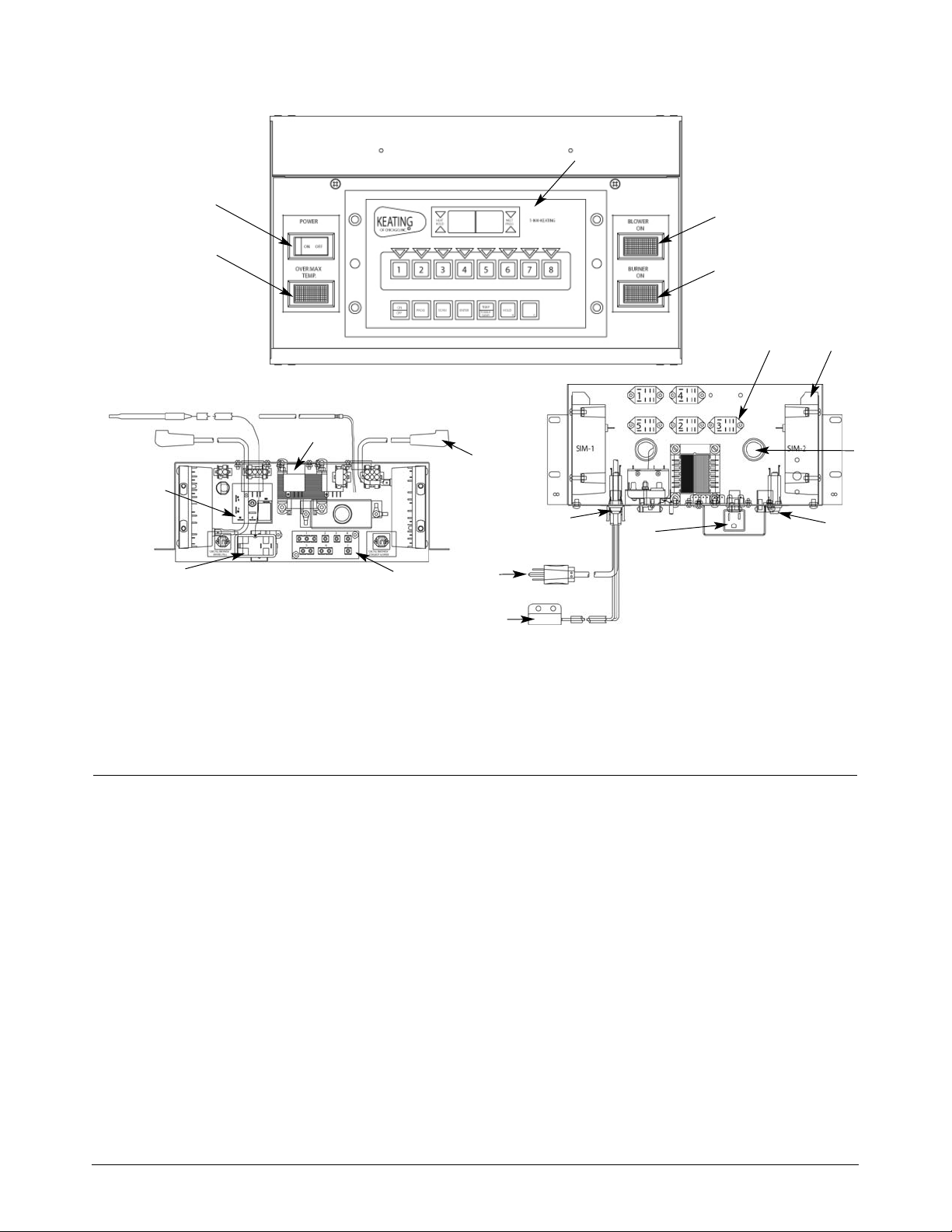
22
IFM CONTROL PANEL PARTS LIST MODEL 2006 CPU
ITEM DESCRIPTION QTY PART NUMBER
1 Indicating Light Red Rectangular 28V 1 021209
2 Switch Rocker On / Off DPST 1 035030
3 Computer 1 031125
Computer probe only (not shown) 1 004776
4 Indicating Light Blue Rectangular 28V 1 032828
5 Indicating Light Amber Rectangular 28V 1 021254
6 Spark Ignition Module 2 037550
7 Relay DPDT 24VAC 5 030844
8 Circuit Breaker 1 053338
9 Receptacle Snap-In 125 VAC 1 011505
10 Transformer 120V-24V 1 024032
11 Snap-In Bushing 1” 3 005664
12 Terminal Board with Insulation 1 004153
13 High Limit (Resettable) 1 034357
14 Strain Relief Bushing 1 000430
15 Power Cord 120V 9ft. 1 006311
16 Spark Ignition Cables 2 037551
17 Relay 35 Seconds 1 058684
18* Safety Switch Magnetic Reed 1 053777
*Not available on all models
2
1
4
5
Back Panel (Top View)
Back Panel (Front View)
3
7
6
11
8
9
18
15
14
10
16
12
13
17
Page 25
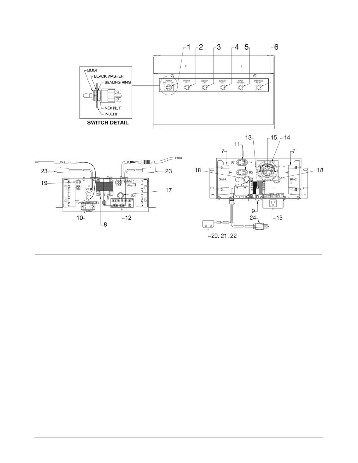
23
BOB EVANS IFM CONTROL PANEL PARTS LIST(FRONT/REAR DRAIN - CONCEALED THERMOSTAT - NO
TIMERS) MODEL 2006
ITEM DESCRIPTION QTY PART NUMBER
1 Switch Toggle Sealed On-Off 1 056056
2 Indicating Light Clear Round 28V 1 057863
3 Indicating Light Blue Round 28V 1 057862
4 Indicating Light Amber Round 28V 1 056588
5 Indicating Light Green Round 28V 1 056587
6 Indicating Light Red Round 28V 1 057861
7 Spark Ignition module IFM 24VAC 2 037550
8 Transformer Stepdown 24VAC 80VA 1 024032
9 Circuit Breaker 3 AMP 1 POLE 250V 1 053338
10 High limit Manual Reset 1 034357
11 Relay DPDT 24VAC 2 030844
12 Terminal Board with Insulation 1 004153
13 Thermostat - 14"Model 1 035574
Thermostat - 18" & 20" Models 1 035575
14 Thermostat Dial Plate 375° 1 058037
15 Thermostat Knob 1 004163
16* Receptacle 125V 15A Snap-In 1 011505
17 Bushing - Black Plastic Snap-In 7/8” 1 000514
18 Bushing - Black Plastic Snap-In 1” 2 005664
19 Bushing Strain Relief 1 000470
20* Switch Magnetic Safety N.C. 1 053777
21 Connector 2 Circuit Quick Plug 1 032208
22 Connector Contact Pin Male 2 032208
23 Spark Ingition Electrode Lead 24” 2 037551
24 Power Cord 9’ 120V 1 006311
*LOCATED ON REAR DRAIN UNITS ONLY
Back Panel (Front View)
Back Panel (Top View)
Page 26
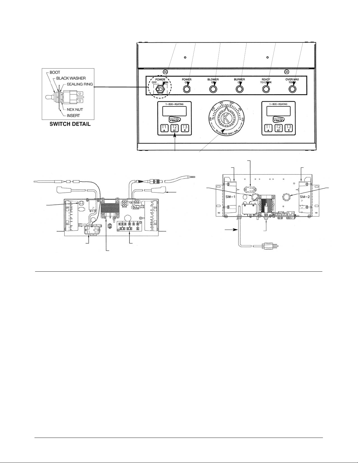
24
IFM CONTROL PANEL PARTS LIST(FRONT DRAIN WITH TIMERS) MODEL 2006 - 14” SIZE
ITEM DESCRIPTION QTY PART NUMBER
1 Switch Toggle Sealed On-Off 1 056056
2 Indicating Light Clear Roundt 28V 1 057863
3 Indicating Light Blue Round 28V 1 057862
4 Indicating Light Amber Round 28V 1 056588
5 Indicating Light Green Round 28V 1 056587
6 Indicating Light Red Round 28V 1 057861
7 Timer Digital 24/120V 2 056921
8 Thermostat Knob 1 004163
Thermostat Dial Plate 1 058037
Thermostat - 14” Model 1 035574
Thermostat - 18” & 20” Models 1 035575
9 Spark Ignition Electrode Lead 24" 2 037551
10 Bushing Strain Relief 1 000470
11 High Limit Manual Reset 1 034357
12 Transformer Stepdown 24VAC 80VA 1 024032
13 Terminal Board wtih Insulation 1 004153
14 Spark Ignition Module IFM 24VAC 1 037550
15 Relay DPDT 24VAC 1 030844
16 Black Plastic Snap-In Bushing 1" 1 005664
17 Black Plastic Snap-In Bushing 1" 1 005664
18 Circuit Breaker, 3 AMP 1 POLE 250V 1 053338
19 Power Cord 9’ 120V 1 006311
1
2
34 5 6
7
9
8
10
11
12
13
14
15
14
16
18
17
Back Panel (Front View)
Back Panel (Top View)
19
Page 27
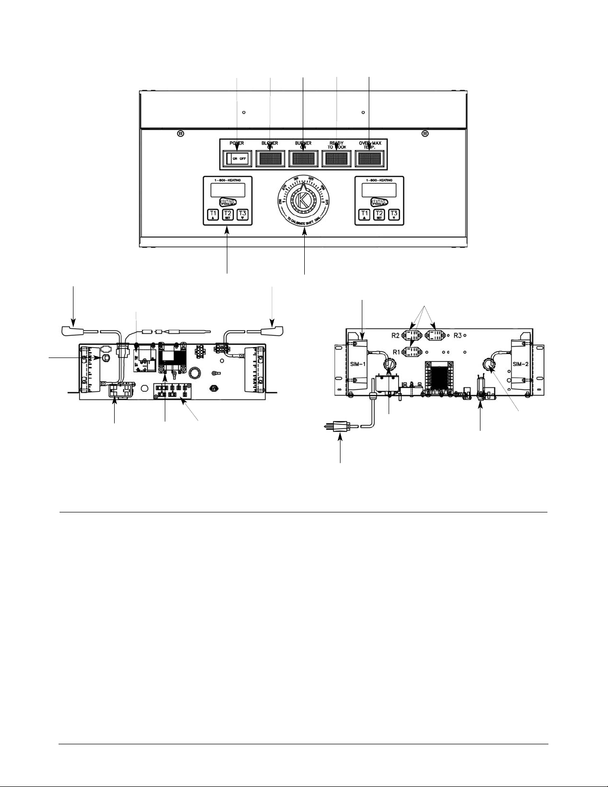
25
IFM CONTROL PANEL PARTS LIST(FRONT DRAIN WITH TIMERS) MODEL 2007 - 18” & 20” SIZE
ITEM DESCRIPTION QTY PART NUMBER
1 Switch Rocker On / Off DPST 1 035030
2 Indicating Light Blue Rectangular 28V 1 032828
3 Indicating Light Amber Rectangular 28V 1 021254
4 Indicating Light Green Rectangular 28V 1 021255
5 Indicating Light Red Rectangular 28V 1 021209
6 Timer Digital 24/120V 2 056921
7 Thermostat 2 035575
Thermostat Dial Plate 250-375° 1 058037
Thermostat Knob 1 004163
8 Spark Ignition module IFM 24VAC 2 037550
9 Transformer Stepdown 24VAC 80VA 1 024032
10 Circuit Breaker 3 AMP 1 POLE 250V 1 053338
11 High limit Manual Reset 1 034357
12 Relay DPDT 24VAC 3 030844
13 Relay 35 Seconds 1 058684
14 Terminal Board wtih Insulation 1 004153
15 Bushing - Black Plastic Snap-In 1” 2 005664
16 Spark Ignition Electrode Lead 24" 2 059303
17 Bushing Strain Relief 1 000470
18 Power Cord 9’ 120V 1 006311
Back Panel (Front View)
Back Panel (Top View)
1
2
3
4
5
6
7
8
9
10
11
12
13
14
15
15
16
16
17
18
Page 28
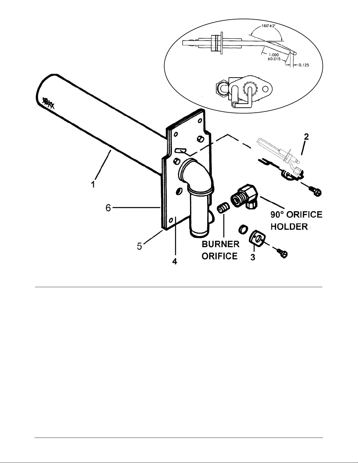
26
Figure 7-2 IFM Burner Assembly (Right Side Shown)
ITEM DESCRIPTION QTY PART NUMBER
1 BURNER REPLACEMENT KIT 1 016506
(BURNER WITH ITEMS 5 & 6)
2 SPARK ELECTRODE REPLACEMENT KIT 1
NATURAL GAS 052562
LP GAS 052908
3 OBSERVATION WINDOW ASSEMBLY
LENS 016101
COVER 1 015905
4 BURNER OUTER PLATE & ELBOW ASSEMBLY
(LEFT OR RIGHT SIDE) 1 022158
5 BURNER TO PLATE SEALING GASKET 1 016505
6 BURNER TO TUBE SEALING GASKET 2 016504
Critical Dimensions for proper spark ignitor gap
(Ref. #2).
Page 29
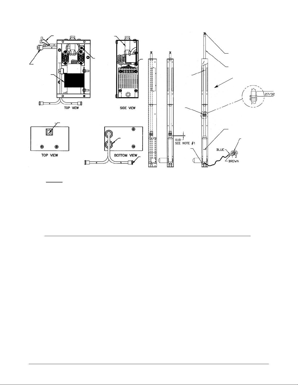
27
DESCRIPTION QTY PART #
1 TRANSFORMER 120/208/240/480V 1 056036
2* CIRCUIT BREAKER 3A/250V 1 053338
3 RELAY DPDT 24V AC 2 030844
4 RECTIFIER 1 018321
5 POWER CORD 1 021289
6 CONNECTION 3 CIRCUITS PLUG 1 032210
7 CONNECTOR 2 CIRCUIT CAP 2 032207
8 COVER FOR CIRCUIT BREAKER 1 054664
9 PUSH ROD 1 018096
10 SCREW
1
/4"-20" X 11/4" 1 021091
HEX NUT1/4-20 1 016383
11 COUPLER ACTUATOR BL 1 054525
RETAINING RING 2 054540
PIN COUPLER ACTUATOR BL 2 054503
12 ACTUATOR 24V DC 1 054510
13 SHAFT ACTUATOR LOWER BL S/S 1 054522
14 CONNECTOR 2 CIRCUIT QUICK 1 032208
CONNECTOR CONTACT PIN MALE 2 028309
15 PIN BASKET LIFT NON ROTATIONAL 1 054760
Basket Lift Power Supply Box Basket Lift Assembly
*This circuit breaker can be found under the control panel on newer units.
6
5
1
2
4
3
8
7
10
9
15
11
14
12
13
Housing
NOTES
1. A minimum distance of 3/16" and maximum distance of 1/4" should be maintained when actuator
is at full downward stroke. Item 11 should never be bottomed on item 12 when in this location.
2. Actuator shaft should travel 6
1
/2" upward from lowest position.
3. Distance are to be measured when actuator is powered.
4. Apply light coating of food grade grease to Item 9 on entire shaft inside housing.
Page 30
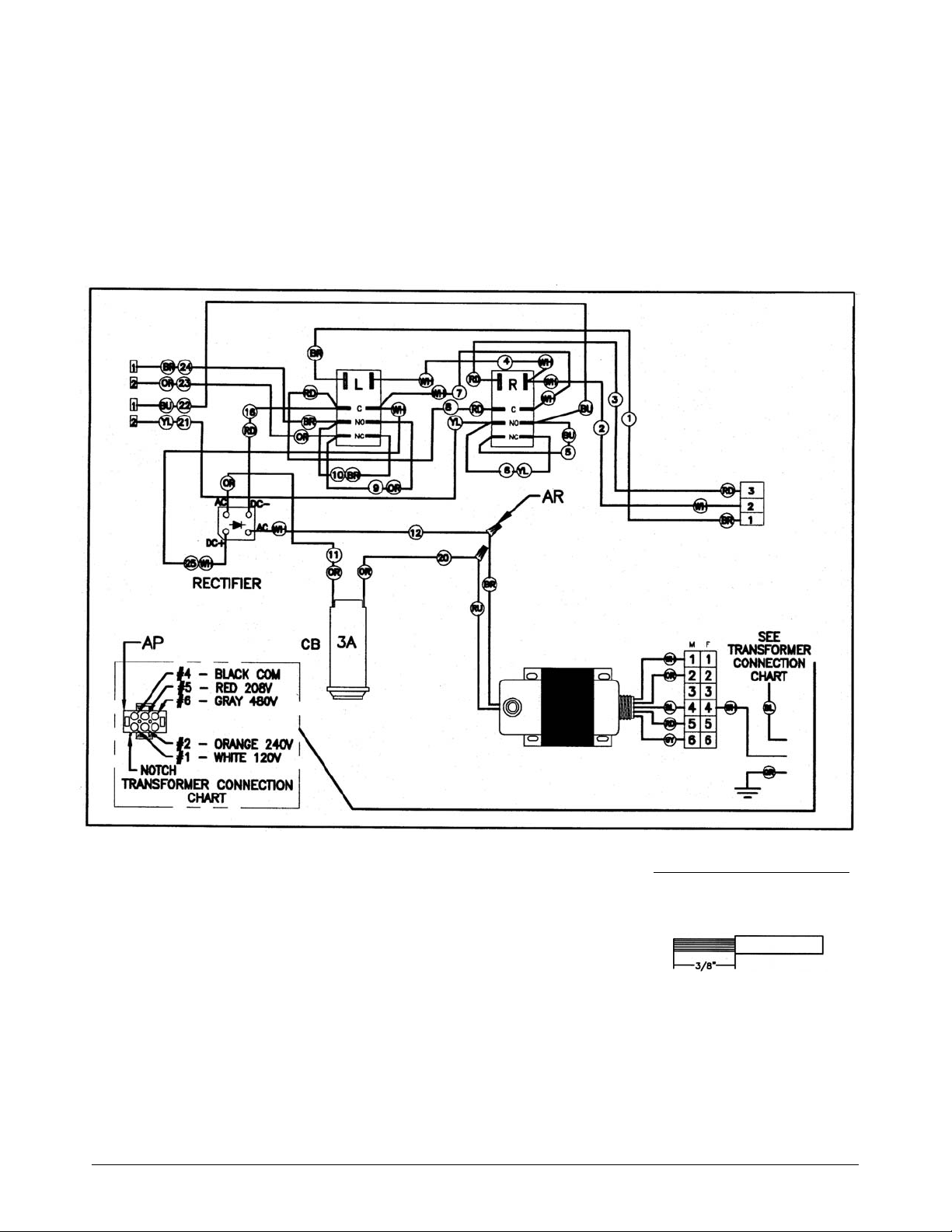
28
Single Basket Lift Power Supply Box
NOTES:
1. Wire Material: See wires
specification
2. Remove 3/8” of insulation
from end of wire
3. Route all wires so they lay
flat and are organized in
appearance.
4. Tug test all wires connect-
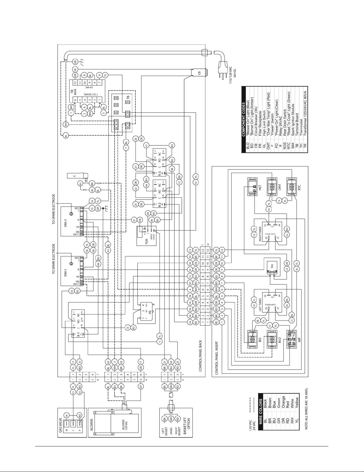
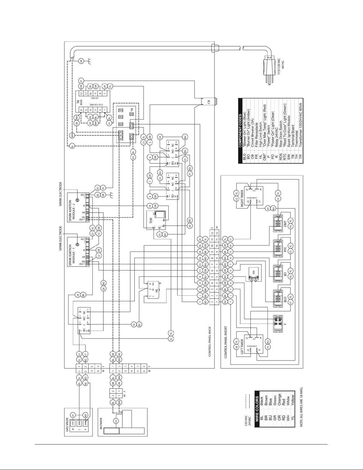
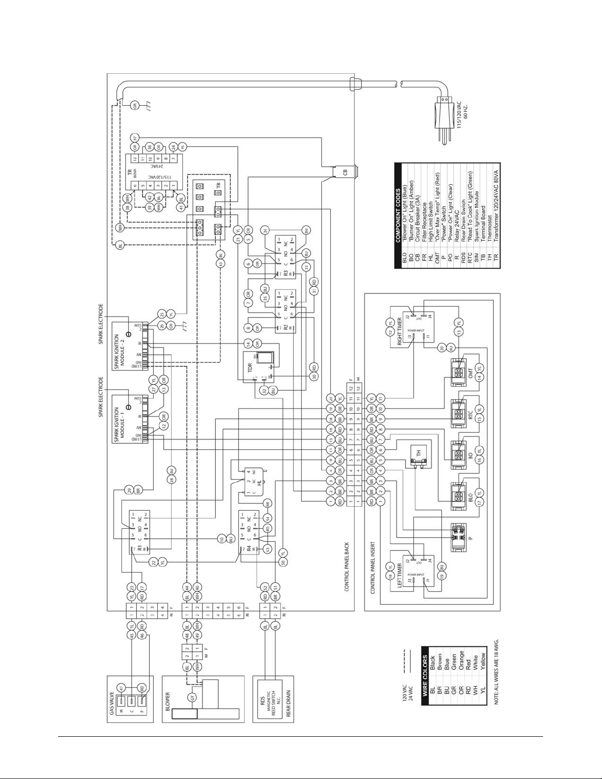
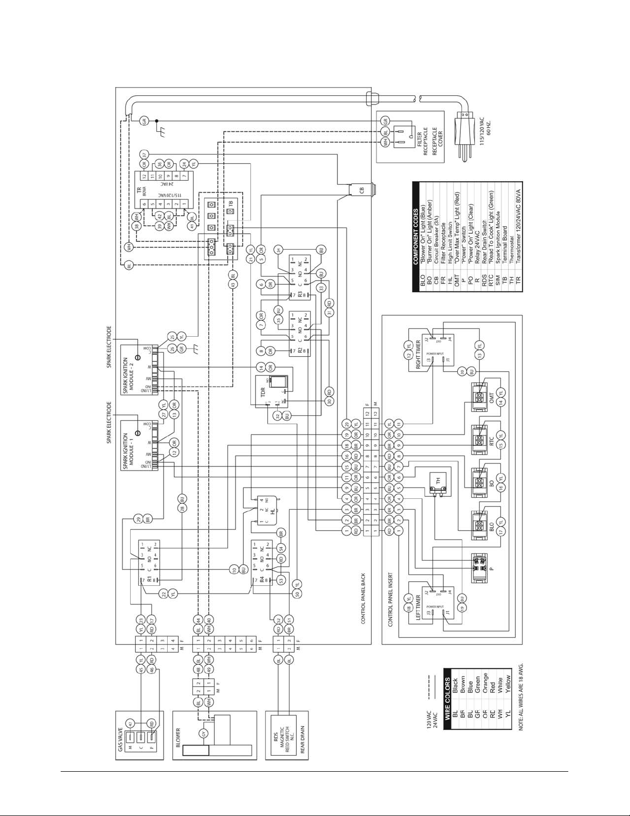
NOTE: A separate wiring diagram has been included with this manual and should be saved for troubleshooting and
maintaining the fryer. The wiring diagrams in this section cover standard fryers which may or may not match the
diagram sent with the fryer. Non-standard fryers such as CPU models, etc., do not have wiring diagrams printed
in this section.
WIRING DIAGRAMS
Page 31
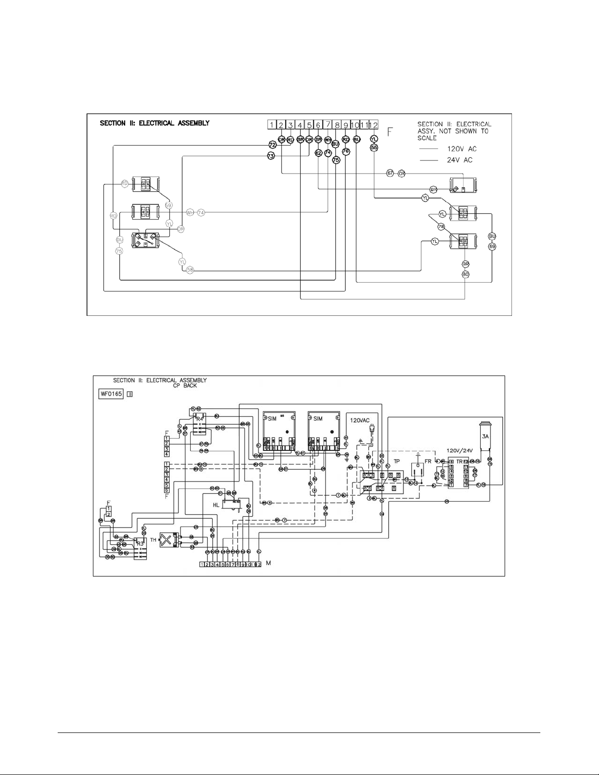
29
14 IFM 120V CONNECTION DIAGRAM - NO TIMERS, FRONT DRAIN - MODEL 2000
CONTROL PANEL INSERT
CONTROL PANEL BACK
Page 32
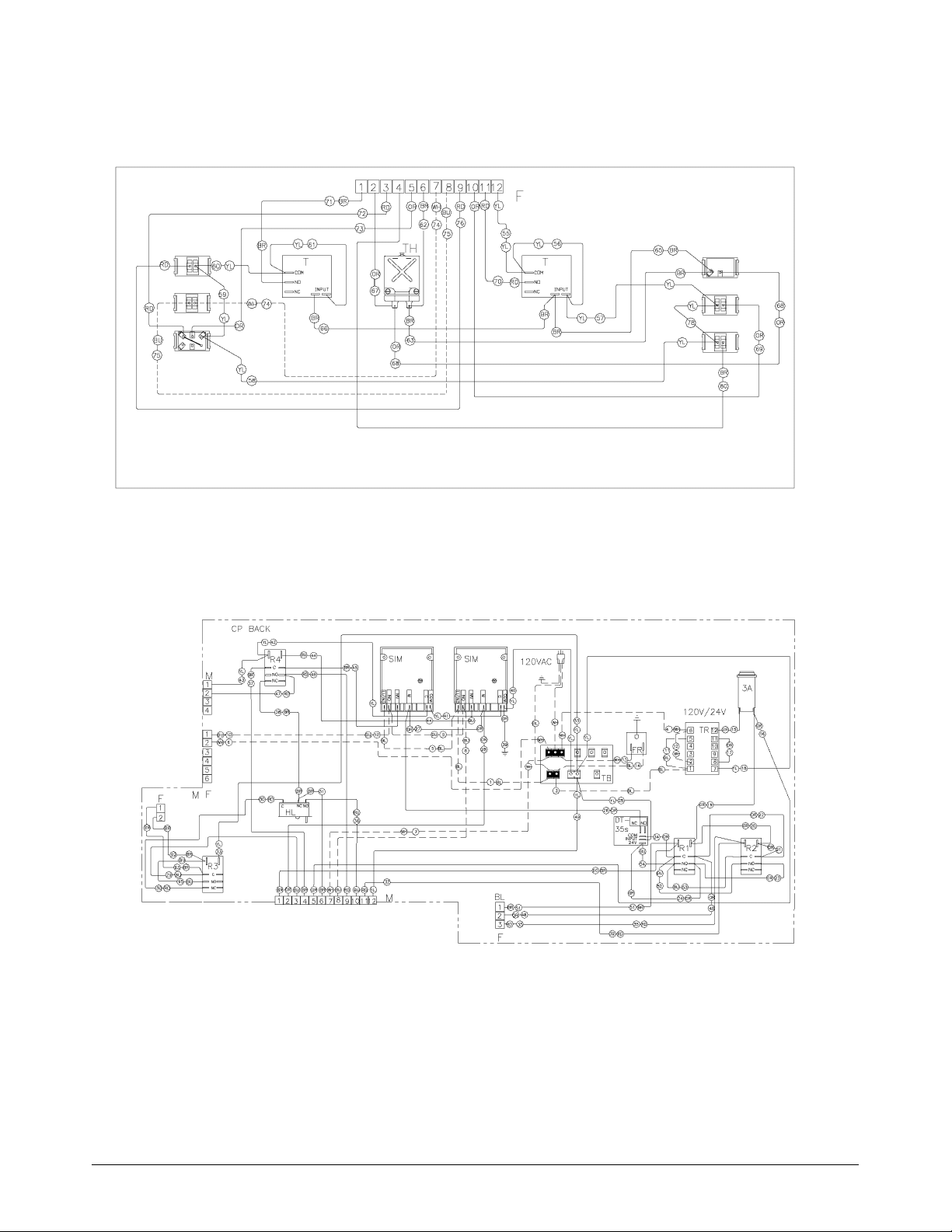
30
CONTROL PANEL INSERT
IFM - 120V CONNECTION DIAGRAM - TIMERS, FRONT DRAIN
WITH LIGHTED ROCKER SWITCH - MODEL 2000
CONTROL PANEL BACK
Page 33
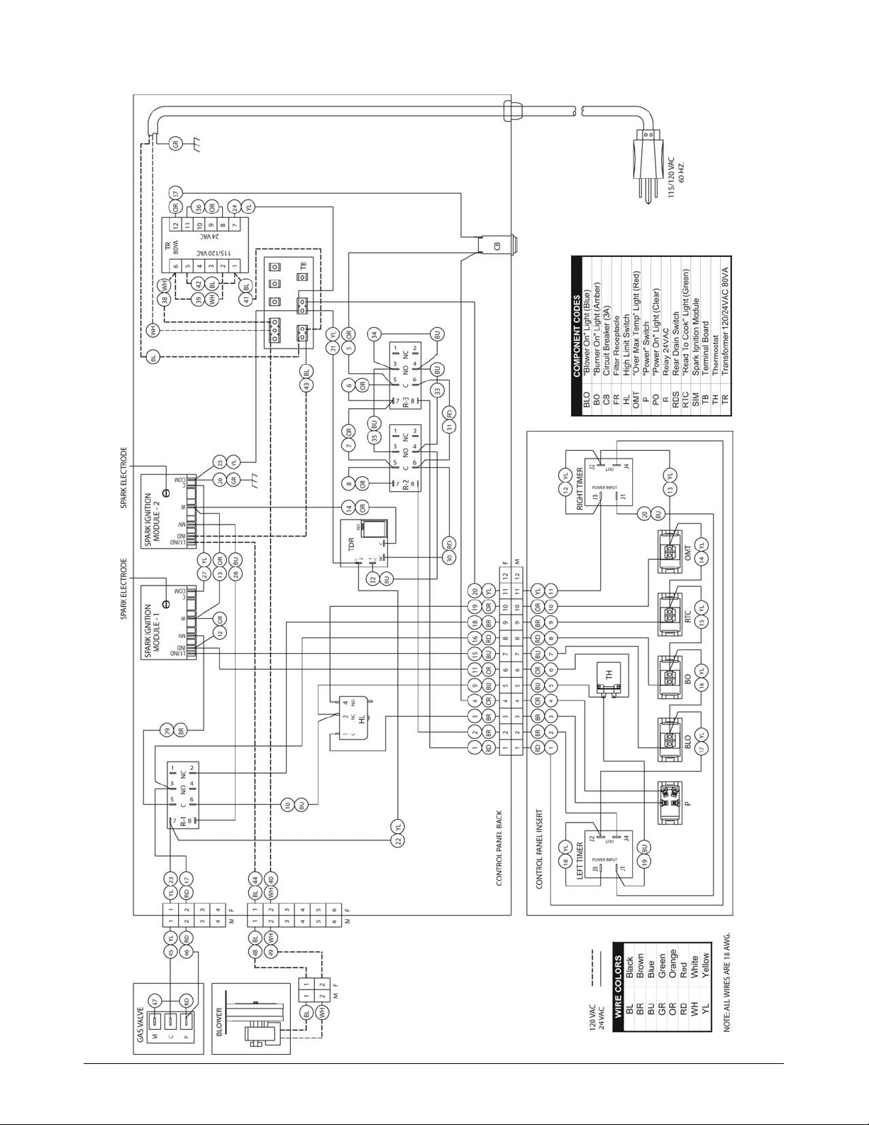
31
14 IFM - MODEL 2006 FRONT DRAIN WITHOUT LIGHTED ROCKER SWITCH
Page 34
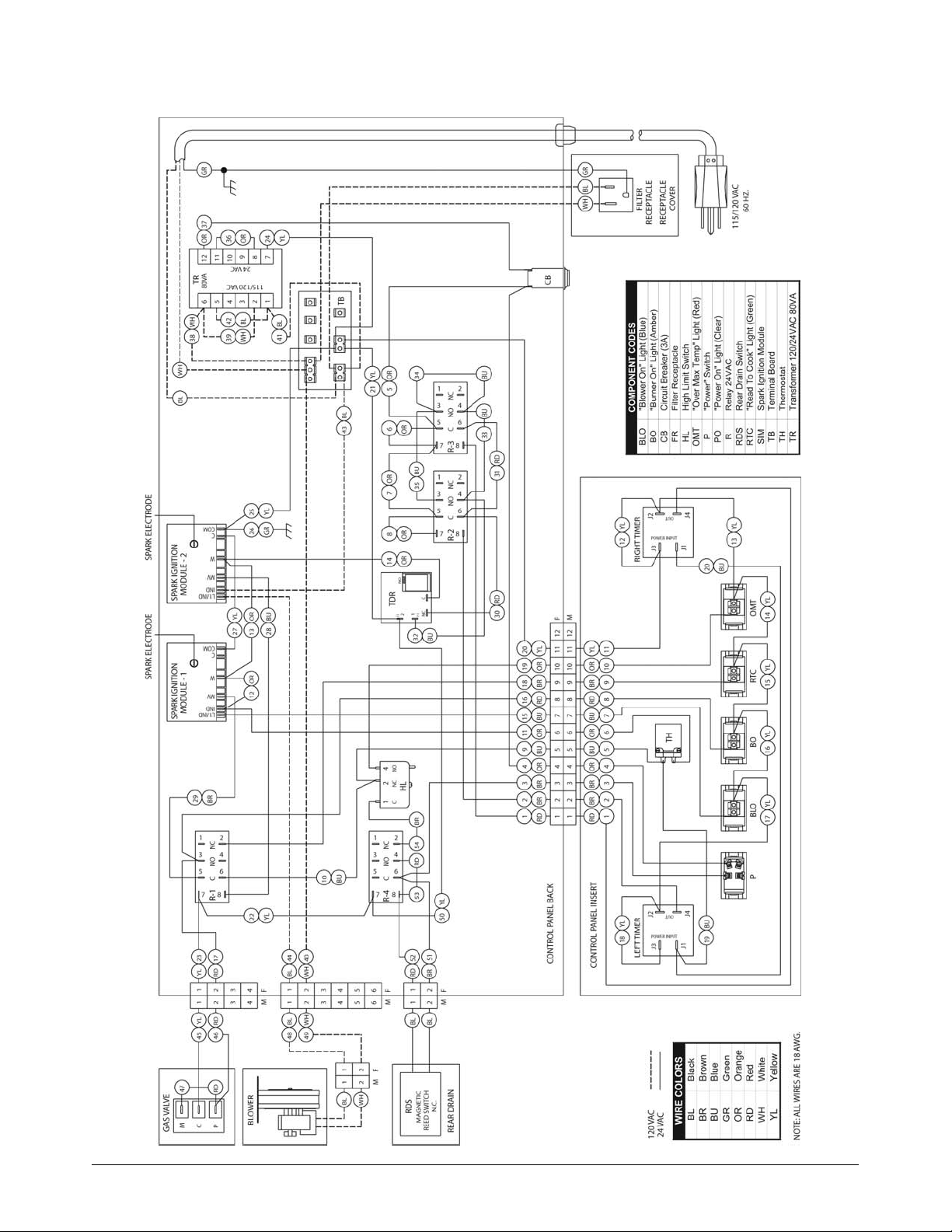
32
14 IFM - MODEL 2006 WITH SAFE AND EASY®FILTER
Page 35
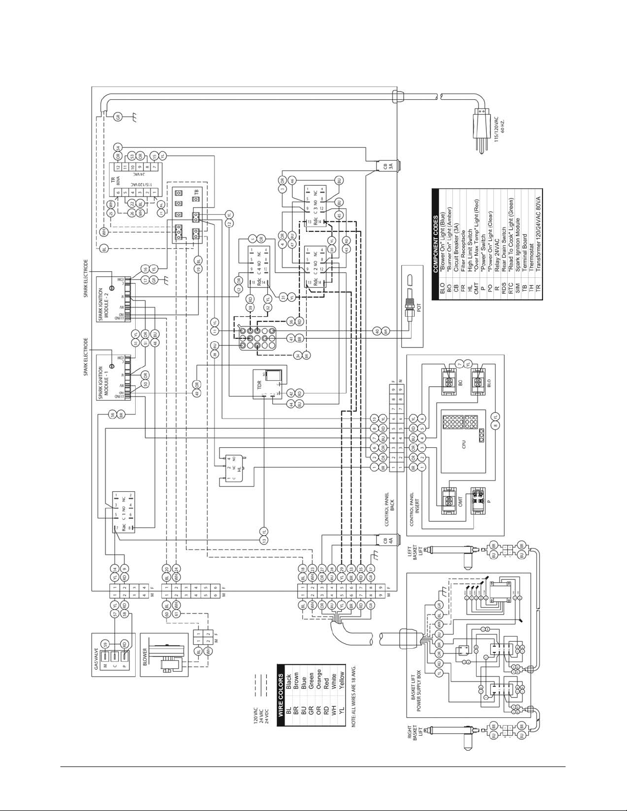
33
14 IFM - MODEL 2006 CPU BASKET LIFT FRONT DRAIN
Page 36
34
18 & 20 IFM - MODEL 2006 FRONT DRAIN WITH LIGHTED ROCKER SWITCH
Page 37
35
18 & 20 IFM - MODEL 2007 FRONT DRAIN WITHOUT LIGHTED ROCKER SWITCH
Page 38
36
18 & 20 IFM - MODEL 2007 REAR DRAIN WITHOUT LIGHTED ROCKER SWITCH
Page 39
37
18 & 20 IFM - MODEL 2007 WITH SAFE AND EASY®FILTER
WITHOUT LIGHTED ROCKER SWITCH
Page 40
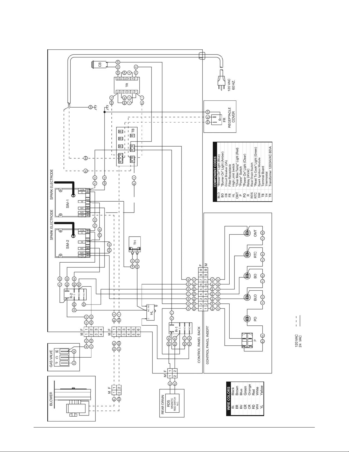
38
BOB EVANS IFM - 120V CONNECTION DIAGRAM - NO TIMERS, REAR DRAIN -
MODEL 2006 WITH TOGGLE SWITCHES
Effective 5/2006
Page 41
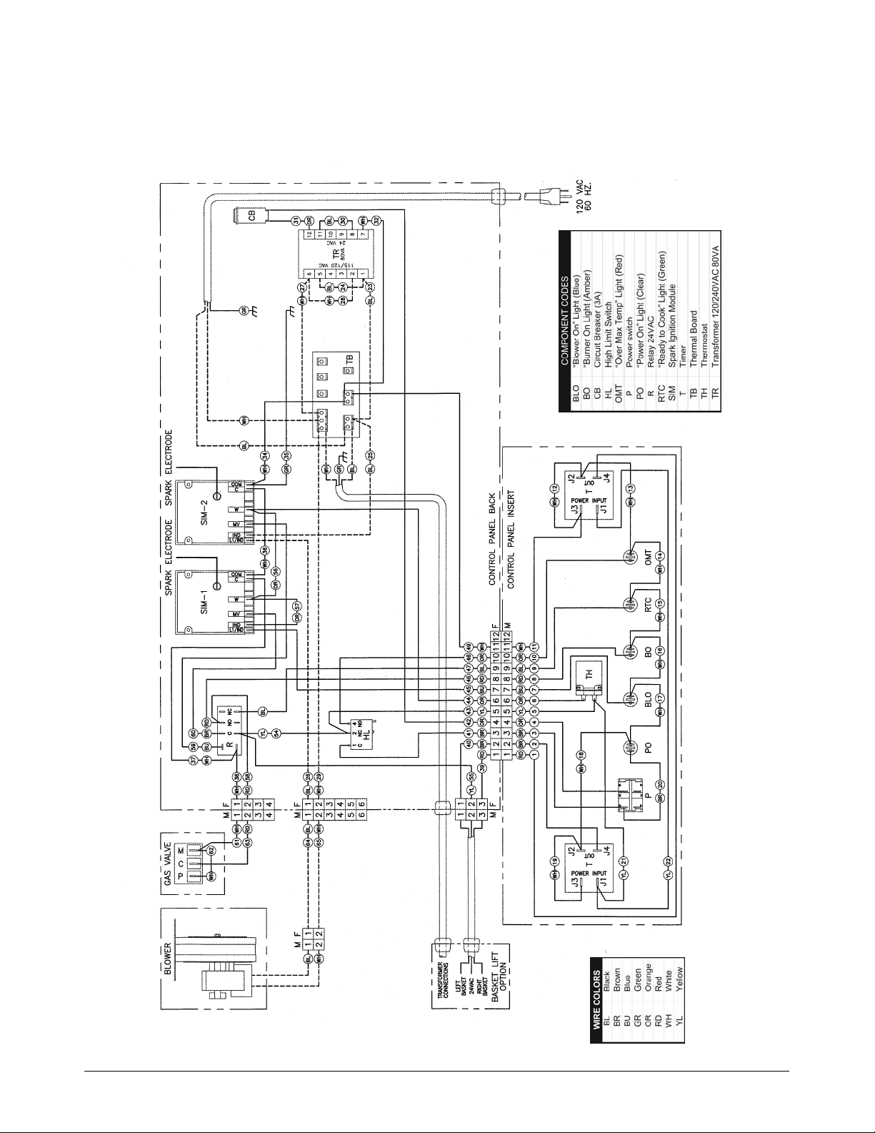
39
IFM 120V CONNECTION DIAGRAM - TIMERS, FRONT DRAIN -
MODEL 2006 WITH TOGGLE SWITCHES
Effective 5/2006
Page 42
L
IMITED
W
ARRANTY
Keating Of Chicago, Inc. ("Keating”) warrants to the original purchaser. ("Customer"), all new Keating Fryers, Filter Systems,
Griddles, Keep Krisp®, Custom Pasta Systems, Top-Side™ Cookers, Computer Timers, Fryer
& Pasta Vessels, and Keating replacement parts ("products") installed after June 1, 1994 to be free to defects in material or w
orkmanship, subject to the following terms and conditions.
L
ENGTH
O
F
W
ARRANTY
All products other than Fryer & Pasta Vessels and replacement parts shall be warranted for a period of one year from the date o
f original equipment installation. Keating replacement parts are warranted for a period of nine-
ty days from the date of installation. Fryer & Pasta Vessels are warranted as described below.
F
RYER
& P
ASTA
V
ESSEL
W
ARRANTY
Fryers purchased after June 1, 1994 carry a prorated vessel warranty on defects in materials or workmanship to the Customer bas
ed on the following scale:
Time from Installation Date Fryer Vessel Warranty Credit
13-60 months 100%
61-72 months 80%
73-84 months 60%
85-96 months 40%
97-108 months 20%
109-120 months 10%
The credit for the defective fryer & pasta vessel shall be applied against the cost of the replacement vessel, utilizing Keatin
g's then current price, upon return of the vessel to Keating, (freight to be paid by Keating within
the first 2 months only), only during the first 60 months, subject to the limitations described below.
L
IMITATIONS
O
F
L
IABILITY
In the event of warranty claim or otherwise, the sole obligation of Keating shall be the repair and/or replacement at the optio
n of Keating of the product or component or part thereof. Such repair or replacement shall be
at the expense of Keating except that the Customer shall pay the following expenses: all freight and labor expense for Keating
replacement parts; for all other products, mileage exceeding 50 miles or travel more than one
hour, labor costs of more than one person, overtime rates, truck charges, difference between ground and other mode of transport
ation, and holiday charges. Any repair or replacement under this Limited Warranty does not
constitute an extension of the original warranty for any period for the product or for any component or part thereof. Parts to
be replaced under this Limited Warranty will be repaired at the option of Keating with new or
functionally operative parts. Keep Krisps and Computer Timers must be returned to Keating for warranty repair or replacement. F
ield repairs of those items are not authorized.
THE LIABILITY OF KEATING ON ANY CLAIM OF ANY KIND, INCLUDING CLAIMS BASED ON WARRANTY, EXPRESSED OR IMPLIED, CONTRACT, NEGLIGEN
CE, STRICT LIABILITY OR ANY
OTHER THEORIES SHALL BE SOLELY AND EXCLUSIVELY THE REPAIR OR REPLACEMENT OF THE PRODUCT AS STATED HEREIN, AND SUCH LIABILITY SH
ALL NOT INCLUDE, AND CUSTOMER
SPECIFICALLY RENOUNCES ANY RIGHTS TO RECOVER, SPECIAL, INCIDENTAL, CONSEQUENTIAL OR OTHER INJURIES TO PERSONS OR DAMAGE TO PROP
ERTY, LOSS OF PROFITS OR
ANTICIPATED PROFITS, OR LOSS OF USE OF THE PRODUCT.
If any oral statements have been made regarding the Keating products, such statements do not constitute warranties and are not
part of the contract sale. This Limited Warranty constitutes the complete, final and exclu-
sive statement with regard to warranties.
THIS LIMITED WARRANTY IS EXCLUSIVE AND IS IN LIEU OF ALL OTHER WARRANTIES WHETHER WRITTEN, ORAL, STATUTORY OR IMPLIED, INCLUDIN
G BUT NOT LIMITED TO ANY WAR-
RANTY OF MERCHANTABILITY OR FITNESS FOR PARTICULAR PURPOSE OR WARRANTY AGAINST LATENT DEFECTS.
E
XCLUSIONS
The warranties provided by Keating of Chicago, Inc. do not apply in the following instances:
1. Defects arising out of or resulting from improper installation or maintenance, abuse, misuse, modification or alteration by u
nauthorized service personnel, or any other condition not attributable to a defect in material or
workmanship. Proper installation and maintenance are the responsibility of the installer and Customer, respectively. Proper ins
tallation and maintenance procedures are prescribed by the Keating Service Manual.
2. In the event that the product was damaged after leaving the factory due to flood, fire, other acts of God or accident, damage
during shipment should be reported to the carrier and is not the responsibility of Keating.
3. In the event the serial number or rating plate has been removed from the product or altered.
4. On parts which would normally be worn or replaced under normal conditions, including but not limited to electric bulbs, fuses
, interior and exterior finishes, gaskets and radiants.
5. With regard to adjustments and calibrations such as leveling, tightening of fasteners or plumbing connections, improper gas p
ressure or improper electrical supply, the checking of and changes in adjustment and
calibrations are the responsibility of the installer. Proper installation procedures are prescribed by the Keating Service Manu
al.
6. In the event of unauthorized repairs or alterations to the Keating product.
7. With the use of sodium chloride in pasta vessels or harsh chemicals in fryer or pasta vessels.
O
THER
T
ERMS AND
C
ONDITIONS
The Customer must provide proof of purchase from Keating.
This Limited Warranty is valid in the 50 United States, its territories, and Canada, and is void elsewhere.
Keating products are sold for commercial use only. If any Keating product is sold as a component of another product or used as
a consumer product, such Keating product is sold As Is without any warranty.
If any provision of this Limited Warranty is held to be unenforceable under the law of any jurisdiction, such provision shall b
e inapplicable in such jurisdiction, and the remainder of the warranty shall remain unaffected.
Further in such event, the maximum exclusion or limitation allowable under applicable law shall be deemed substituted for the u
nenforceable provision.
This Limited Warranty shall be governed by and construed in accordance with the laws of the State of Illinois.
T
O
S
ECURE
W
ARRANTY
S
ERVICE
All repair services under this Limited Warranty must be authorized by Keating or performed at Keating. Authorization may be obt
ained by calling 1-800-KEATING within the Continental United States, Alaska, Hawaii,
Puerto Rico and Canada during normal business hours (8 a.m. through 5 p.m. Central Time, Monday through Friday). When calling,
please have the following information available: (1) name, address and
telephone number of the Customer; (2) location of product, if different; (3) name, model number and serial number of the produc
t; (4) installation date; and (5) description of defect. Keating will then issue a service author-
ization work order number to one of its approved independent servicing organizations, or request the product or part be shipped
to Keating for repair or replacement, as appropriate. Any defective part subject to a claim
under this Limited Warranty must be shipped freight prepaid to Keating for testing and examination. Keating's decision as to th
e cause and nature of any defect under this Limited Warranty shall be final.
K
EATING
K
EATING OF
C
HICAGO
, I
NC
., 1-800-KEATING,
WWW
.
KEATINGOFCHICAGO
.
COM
REFILE/warranty 8/07
WARRANTY
Page 43

SERVICE INFORMATION
If you have a service related question call 1-800-KEATING.
Please state the nature of the call; it will ensure speaking with the appropriate person.
Have your serial and model number available when ordering parts.
KEATING OF CHICAGO, INC.
8901 W. 50th Street, McCook, Illinois 60525-6001
Phone: (708) 246-3000 FAX: (708) 246-3100
Toll Free 1-800-KEATING (In U.S. and Canada)
www.keatingofchicago.com
*As continuous product improvement occurs, specifications may be changed without notice.
KEATING LIMITED WARRANTY CARD
PLEASE COMPLETE AND MAIL AT ONCE–WARRANTY IS NOT IN EFFECT UNTIL CARD IS RETURNED.
WARRANTY CARD IS ALSO AVAILABLE TO COMPLETE ON LINE AT YOUR CONVENIENCE.
COMPANY: __________________________________________________________________________________________________________________
ADDRESS: __________________________________________________________________________________________________________________
CITY: ______________________________________________________________________________ STATE: ________________ ZIP: ____________
DEALER: ____________________________________________________________________________________________________________________
DATE OF PURCHASE: ________________________________________________________________ INVOICE NUMBER: ____________________
SERIAL NUMBER: ________________________________________ FRYER FILTER SYSTEM GRIDDLE
REMARKS: ______________________________________________ TOP-SIDE COOKER HOT PLATE CUSTOM PASTA
I HAVE READ THE INSTALLATION AND OPERATION INSTRUCTIONS.
SIGNED: ____________________________________________________________________________________ DATE: __________________________
“Serving Those Who Serve The Very Best”
®
 Loading...