

Page 1
MIRACLEAN
®
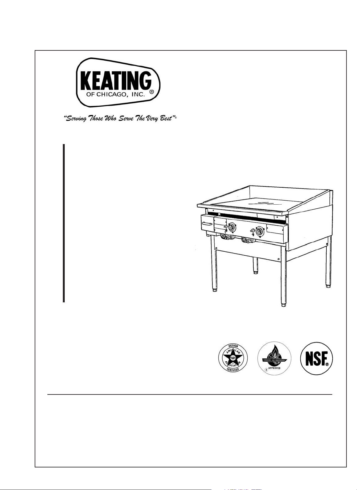
GAS GRIDDLE
SERVICE
MANUAL
KEEP THIS MANUAL FOR TRAINING NEW PERSONNEL
1-800-KEATING
www.keatingofchicago.com
Page 2

i
TABLE OF CONTENTS
SECTION I INTRODUCTION
Safety Precautions . . . . . . . . . . . . . . . . . . . . . . . .1-2
SECTION II INSTALLATION
Installation . . . . . . . . . . . . . . . . . . . . . . . . . . . . . . . .2
Damage During Shipment . . . . . . . . . . . . . . . . . . . .2
Positioning . . . . . . . . . . . . . . . . . . . . . . . . . . . . . . . .2
Leveling . . . . . . . . . . . . . . . . . . . . . . . . . . . . . . . . . .3
Restraining Devices . . . . . . . . . . . . . . . . . . . . . . . . .3
Gas Connection . . . . . . . . . . . . . . . . . . . . . . . . . . . .3
Gas Leak Testing . . . . . . . . . . . . . . . . . . . . . . . . .3-4
SECTION III OPERATING
Lighting . . . . . . . . . . . . . . . . . . . . . . . . . . . . . . . . . .4
Conditioning . . . . . . . . . . . . . . . . . . . . . . . . . . . . .4-5
Cooking . . . . . . . . . . . . . . . . . . . . . . . . . . . . . . . . . .5
Griddle Surface . . . . . . . . . . . . . . . . . . . . . . . . . .5-6
Cleaning . . . . . . . . . . . . . . . . . . . . . . . . . . . . . . . . . .6
Shutdown . . . . . . . . . . . . . . . . . . . . . . . . . . . . . . . . .6
SECTION IV MAINTENANCE
Warranty Repairs . . . . . . . . . . . . . . . . . . . . . . . . . . .6
Preventive Maintenance . . . . . . . . . . . . . . . . . . . . .6
Cleaning . . . . . . . . . . . . . . . . . . . . . . . . . . . . . . . . . .7
Limited Calibration . . . . . . . . . . . . . . . . . . . . . . . . . .7
SECTION V SERVICE DIAGNOSIS
Trouble Shooting Chart . . . . . . . . . . . . . . . . . . . . . .8
SECTION VI PARTS LIST
Ordering Parts . . . . . . . . . . . . . . . . . . . . . . . . . . . . .8
Warning and Operating Plates . . . . . . . . . . . . . . . .8
Miraclean® Gas Griddle Assembly . . . . . . . . . . . . .8
Control Panel Assembly . . . . . . . . . . . . . . . . . . . . .9
Heating Element Assembly . . . . . . . . . . . . . . . . . .9
SECTION VII WIRING DIAGRAM
Gas Griddle Wiring Diagram . . . . . . . . . . . . . . . . .10
Warranty . . . . . . . . . . . . . . .Back Inside Cover Page
Warranty Card . . . . . . . . . . . . . . . . . . . . . . . . .Insert
GasGrid pre2000 0107
09/07
Page 3
WARNING
IMPROPER INSTALLATION, ADJUSTMENT, ALTERATION, SERVICE OR
MAINTENANCE CAN CAUSE PROPERTY DAMAGE, INJURY OR DEATH. READ
THE INSTALLATION, OPERATING AND MAINTENANCE INSTRUCTIONS
THOROUGHLY BEFORE INSTALLING OR SERVICING THIS EQUIPMENT.
ii
FOR YOUR SAFETY
DO NOT STORE OR USE GASOLINE OR OTHER FLAMMABLE
VAPORS OR LIQUIDS IN THE VICINITY OF THIS OR ANY OTHER
APPLIANCE.
IMPORTANT
IN THE EVENT A GAS ODOR IS DETECTED, SHUT
DOWN UNITS AT MAIN SHUT OFF VALVE AND
CONTACT THE LOCAL GAS COMPANY OR GAS
SUPPLIER FOR SERVICE.
POST THIS LABEL IN A
PROMINENT LOCATION ON
YOUR UNIT.
NOTE: As continuous product improvement occurs, specifications may be changed without notice.
Page 4

1
I INTRODUCTION
MODEL VARIATIONS
Standard Griddles: Keating MIRACLEAN gas griddles
are available in sizes ranging from 27" to 72" and in
depths 24", 30", 33" and 36". The gas griddles are
AGA, CSA, and NSF design certified.
SAFETY
PRECAUTIONS
WARNING
THIS SYMBOL WARNS YOU THAT SERIOUS
BURNS OR OTHER INJURIES MAY RESULT IF
SAFETY INSTRUCTIONS ARE NOT FOLLOWED.
This service manual should be retained in a safe
place for future reference. The installation of your
new griddle must conform to local codes or in the
absence of local codes, with the current National
Fuel Gas Code ANSI Z223.1 NFPA 54 (latest
edition), Natural Gas Installation Code CAN/CGAB149.1 or Propane Installation Code CAN/CGAB149.2.
Your ventilation hood, when installed, must conform
to the current ANSI/NFPA 96 (latest edition).
No frame or restriction shall be constructed around
the lower part of the MIRACLEAN® that would
restrict air movement into a MIRACLEAN®
combustion area or prevent proper ventilation.
Keating gas griddles are designed to operate on the
gas fuel specified on the serial plate and must not be
operated with another gas fuel. They cannot be
converted to another gas fuel by turning or engaging
a switch.
Your Keating MIRACLEAN® gas griddle is designed
to use only the type of gas indicated on the serial
plate attached to the front of the MIRACLEAN®.
FOR YOUR SAFETY: Do not store
or use gasoline or other
flammable vapors and liquids in
the vicinity of this or any
appliance.
You will post, in a prominent
location, instructions to be followed
in the event the user smells gas.
This information shall be obtained
from your local gas supplier. You
may use the yellow stick-on label
temporarily until you receive the
data from your local gas supplier.
IMPORTANT: In the event a gas odor is detected,
shut down unit at main shut-off valve and contact
the local gas company or gas supplier for
emergency service.
You must maintain this appliance free and clear from
combustibles.
You must maintain the following minimum
clearances for combustible and noncombustible
construction:
Clearances Combustible Noncombustible
Construction
Construction
Back 6" 0"
Right Side 6" 0"
Left Side 6" 0"
You must install this appliance at least 16 inches
away from any open flame.
Adequate clearance for servicing and proper
operation must be maintained. Your Keating
MIRACLEAN® is designed to be serviced from the
front.
Keating commercial griddles are intended for other
than household use.
ALWAYS instruct new employees on proper griddle
operation.
A MIRACLEAN® griddle should be operated ONLY
by properly trained personnel.
ALWAYS turn griddle off each night.
ALWAYS disconnect fuel source before servicing.
NEVER leave a griddle unattended during operation.
NEVER move griddle when hot.
THIS GRIDDLE MAY NOT BE ALTERED, MODIFIED
OR CHANGED IN ANY WAY.
The State of California enacted the California Safe
drinking water and Toxic Enforcement Act of 1986,
(Prop. 65), which “prohibits any person in the course of
doing business from knowingly and intentionally
exposing any individual to a chemical known to the
State of California to cause cancer or reproductive
toxicity without first giving clear and reasonable
warning to such individuals.” The Governor’s Scientific
Advisory Panel added carbon monoxide to the list of
hazardous chemicals known to cause reproductive
harm.
In order to establish full compliance with Proposition
65, we attached a yellow warning label to each gas
fired griddle that Keating of Chicago, Inc.
manufactures. Carbon monoxide would not be present
in concentrations that would pose a “significant risk” to
the consumer when the equipment is installed,
Page 5

2
operated and maintained as follows:
Installed in accordance with all local codes, or in the
absence of local codes, with the current National
Fuel Gas Code Z223.1 (latest edition). National Gas
Installation CAN/CGA-B149.1, or the Propane
Installation Code, CAN/CGA-B149.2.
Installed under a properly designed and operating
exhaust hood.
Connected to the type of gas for which the griddle is
manufactured.
Pressure regulator is installed in the appliance and
adjusted for the manifold pressure marked on the
serial plate.
Adequate air supply to the unit.
In-line pressure regulator, not supplied by Keating,
must be installed outside the appliance.
The equipment is operated in the manner intended
using the proper utensils.
Keep the equipment clean and have it checked
periodically.
Burner air adjustments, mechanical maintenance
and repairs must be performed by qualified service
personnel.
If the equipment is not installed, operated and
maintained in accordance with the above,
concentrations of carbon monoxide in excess of the
established limits could be present in the kitchen
environment.
ALL PERSONNEL IN THE WORK PLACE WHO MAY
BE SUBJECT TO ANY EXPOSURE OF CARBON
MONOXIDE MUST BE WARNED OF SUCH
POSSIBLE EXPOSURE. THIS WARNING SHOULD
BE CONVEYED IN A MANNER SO THAT IT IS
CLEARLY UNDERSTOOD BY THE EMPLOYEE, AND
THE EMPLOYEE SHOULD BE ASKED IF IN FACT HE
OR SHE UNDERSTANDS THE CORRECT METHOD
OF OPERATION OF THE EQUIPMENT AND THAT A
RISK OF EXPOSURE EXISTS IF THE EQUIPMENT
IN OPERATED IMPROPERLY.
WARNING
IF NOT INSTALLED, OPERATED AND MAINTAINED
IN ACCORDANCE WITH THE MANUFACTURER’S
INSTRUCTIONS, THIS PRODUCT COULD EXPOSE
YOU TO SUBSTANCES IN FUEL OR IN FUEL
COMBUSTION WHICH CAN CAUSE DEATH OR
SERIOUS ILLNESS AND WHICH ARE KNOWN TO
THE STATE OF CALIFORNIA TO CAUSE CANCER,
BIRTH DEFECTS OR OTHER REPRODUCTIVE
HARM.
II INSTALLATION
This UNIT must be installed, inspected, calibrated and
serviced by qualified and/or certified and licensed
service personnel - you may void your Keating
warranty if installation is not completed per local,
national and Keating specifications. Contact your
dealer for assistance.
INSTALLATION
Installation must conform with local codes or, in
absence of local codes, with current National Fuel Gas
Code ANSI Z223.1 (latest edition), Natural Gas
Installation Code CAN/CGA-B149.1 or Propane
Installation Code CAN/CGA-B149.2.
NOTE: NOT FOR OUTDOOR INSTALLATION
DAMAGE DURING
SHIPMENT
The griddle has been assembled, tested and inspected
at the factory. Upon arrival, the complete griddle should
be checked for any damage that may have occurred
during shipment.
The carrier is responsible for all damage in transit
whether visible or concealed. Do not pay the freight bill
until the griddle has been thoroughly checked for
damage. If concealed damage is found later, contact
the carrier immediately to file a claim.
What to do if equipment arrives damaged:
VISIBLE LOSS OR DAMAGE – Be certain to note this
on the freight or express receipt and have it signed by
the delivery person.
FILE CLAIM FOR DAMAGES IMMEDIATELY –
Regardless of extent of damage.
CONCEALED LOSS OR DAMAGE – If damage is
noticed when equipment is unpacked, notify the freight
company immediately, and file a “concealed damage
claim”. This MUST be done immediately. Be sure to
retain the shipping container for inspection.
Keating does not assume responsibility for Loss or
Damage incurred in transit.
POSITIONING
The griddle must be no closer than six inches (6") from
any combustible material. The griddle must be placed
under an exhaust hood with a fire retardant system.
Your ventilation hood, when installed, must conform to
ANSI/NFPA 96 (latest edition). ALL connections and
placement must comply with local and national codes.
It is the responsibility of the owner and local installer to
comply with these regulations when installing the
griddle.
Page 6
3
LEVELING
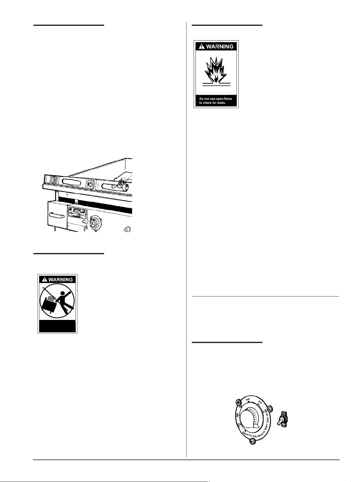
The griddle will operate at its highest efficiency when
properly leveled. Place a level on the griddle plate from
side to side. For griddles on legs, the bottom foot of the
leg is adjustable. Turn counterclockwise to decrease
height or clockwise to increase height until level. For
griddles on stands with casters, the casters are
adjustable by loosening the jam nut and turning the
caster in or out. When the desired level is reached,
tighten the jam nut. Adjustments of more than 3/4" are
not recommended on any caster. The same procedure
should be followed to level the griddle from front to
back.
Figure 2-1
Leveling Griddle
RESTRAINING
DEVICES
On griddle installation on stands with
casters, jam nuts must be completely
tightened. Adequate means must
also be provided to limit the
movement of the appliance without
depending on the connector, the
quick-disconnect device or its
associated piping to limit the
appliance movement.
Connectors must comply with the current ANSI
Z21.69/CAN 1 CAN/CGA 6.16 (latest edition) standard
for connectors for movable gas appliances. Quickdisconnect devices must comply with the ANSI
Z21.41/CAN 1 6.9 (latest edition) standard for quickdisconnect devices for use with gas fuel as applicable.
IF DISCONNECTION OF THE RESTRAINT IS
NECESSARY, IT MUST BE RECONNECTED WHEN
THE MIRACLEAN® GRIDDLE IS RETURNED TO ITS
ORIGINALLY INSTALLED POSITION.
GAS CONNECTION
PIPE JOINT COMPOUNDS
RESISTANT TO PROPANE
GASES MUST BE USED.
BEFORE OPERATING THIS
GRIDDLE, CHECK PIPE
JOINTS FOR LEAKS BY USING
A SOAP AND WATER
SOLUTION ONLY. DO NOT USE
AN OPEN FLAME!
DO NOT SHORT GAS VALVE TERMINALS WHEN
TESTING WIRING, AS THERMOSTAT AND GAS
VALVE DAMAGE MAY OCCUR AND CAUSE
UNSAFE CONDITIONS.
You will post, in a prominent location, instructions to be
followed in the event the user smells gas. This
information shall be obtained from your local gas
supplier. You may use the yellow stick-on label
enclosed on page “ii” temporarily until you receive the
data from your local gas supplier.
Connect the griddle to the main gas supply line at the
rear of the griddle. The piping should be a minimum of
3/4" IPS supply pipe for a single griddle at the burner
manifold. Installation must conform to the current local
and NATIONAL FUEL GAS CODE ANSI Z223.1 /
NFPA 54 (latest edition), Natural Gas Installation Code
CAN/CGA-B149.1 or Propane Installation Code
CAN/CGA-B149.2 (latest edition).
A 3/4" NPT manual gas valve is shipped with each
griddle for field installation. The required gas pressure
for proper operation of each griddle is 4" water column
for natural gas and 10” water column for Propane gas
at the burner manifold.
NOTE: If more than one gas unit is on the same supply
line, you may require a larger line. Consult your local
gas company to assure adequate volume and
pressure. Refer to serial plate for proper gas
requirements for your particular model.
GAS LEAK TESTING
1. Make sure all thermostats, switches and safety
valves are in the “OFF” position.
Figure 2-2
Thermostat
Restraining
devices required.
Page 7
4
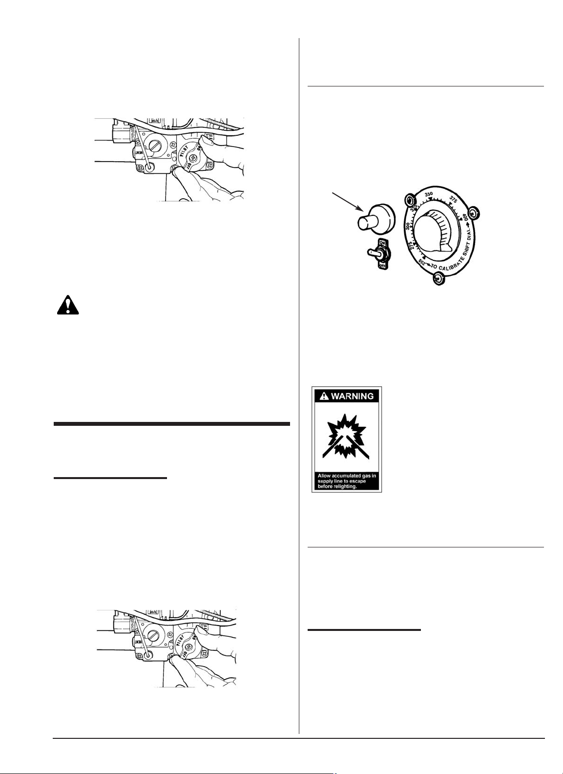
2. Close main and pilot gas supply by partially
depressing and turning ON/OFF knob to the “OFF”
position.
Figure 2-3
Millivolt Safety Pilot Valve
3. Turn main ON/OFF supply line gas valve to the “ON”
position.
4. Have your plumber or gas company representative
check for leaks with a soap solution. (Never check
with a match!)
WARNING
PROPANE GAS MAY EVENTUALLY LOSE ITS
ODOR AND PRECAUTIONS SHOULD BE TAKEN TO
ASSURE THAT PROPANE GAS IS NOT PRESENT
EVEN THOUGH YOU DO NOT DETECT AN ODOR.
IF THERE IS ANY DOUBT, YOU SHOULD CALL
YOUR LOCAL PROPANE GAS SUPPLIER FOR
ASSISTANCE.
III OPERATING
LIGHTING
Lighting instructions are also listed on the lighting
instruction plate attached to the front of the air shield.
1. Turn the ON/OFF switch to the “OFF” position.
2. Turn gas valve knob to pilot position.
Figure 3-1
Millivolt Safety Pilot Valve
3. Depress and hold gas valve knob while repeatedly
pushing red button (Piezo spark ignitor) on control
panel until pilot flame is established. Allow pilot to
burn 90 seconds before releasing gas valve knob.
This will allow the thermopile to reach its maximum
millivolt and milliamp output.
NOTE: Allow pilot to burn one additional minute before
turning thermostat dial to desired position. Pilot flame
should be blue in color and high enough to envelop the
tip of the thermopile to activate the gas safety valve.
Figure 3-2
Piezo Spark Ignitor
4. Turn gas valve knob to “ON” position.
5. Turn ON/OFF switch to “ON” position.
6. Set thermostat dial to desired temperature. When
the griddle plate reaches the temperature setting the
main burners will extinguish.
DURING INITIAL INSTALLATION,
AFTER OVERNIGHT
SHUTDOWN, OR WHEN
RELIGHTING, AIR IN THE
SUPPLY LINE MAY MAKE IT
NECESSARY TO HOLD THE
GAS VALVE IN THE
DEPRESSED PILOT POSITION
FOR A LONGER THAN NORMAL
PERIOD OF TIME. WAIT FIVE
MINUTES BEFORE REPEATING
LIGHTING PROCEDURE TO ALLOW ANY GAS
WHICH MAY HAVE ACCUMULATED IN THE
BURNER COMPARTMENT TO ESCAPE.
NOTE: If you have difficulty lighting the pilot:
1. Place ON/OFF switch to the “OFF” position.
2. Wait five minutes before relighting.
3. Repeat Steps 2 - 6 of Lighting Instructions.
CONDITIONING THE
GRIDDLE
The MIRACLEAN® Griddle plate has been “seasoned”
at the factory. The chrome surface, when heated
creates a thin layer of chrome oxide which acts as a
releasing agent for food product. If you feel you need to
recondition, the following instruction should be
followed:
Page 8
5
1. Follow cleaning instruction on page 7.
2. Heat the MIRACLEAN® to 400°F for one hour.
3. Lower thermostat to 350°F, allowing the
MIRACLEAN® to cool to about 350°F, as is evident
when griddle cycles on or surface thermometer
indicates correct temperature.
4. Lightly coat the MIRACLEAN® surface with
shortening.
COOKING
MIRACLEAN® Griddles are designed to provide
maximum production efficiency and deliver high quality
food products. Follow cooking procedures below for
your model.
1. Set the thermostat to the desired temperature and
wait ten minutes for preheat. Shown are
recommended cooking temperature guides:
NOTE: Because of the superior heating characteristics
and heat retention properties found in the
MIRACLEAN® Griddle, operating temperatures should
be set 10°F to 25°F below conventional griddles.
2. Cook as usual, but after each batch scrape the
griddle in the work area, completely clean, using the
Keating replaceable blade scraper.
3. Locate the inverted “V’s” on the front of the griddle
cooking plate. Depending on your model you may
have from one to five thermostats. The “V’s” indicate
where the thermostat sensing bulbs are located
below the plate. See Figure 3-3.
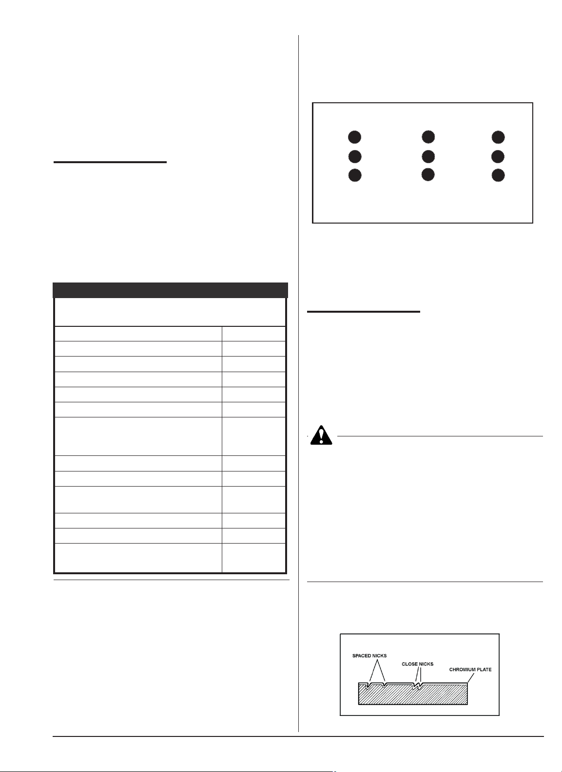
4. Load the product to the left and right of each inverted
“V” first, then fill the area above the thermostat
sensing bulb. See figure 3-3.
Figure 3-3
Sample configuration of proper food placement
If you cook over the sensing bulb only, you are drawing
heat from that section, thus activating the thermostat to
call for more heat even though the area around it is still
at the temperature setting. This will result in higher
surface temperatures which will affect your cooking
and possibly product appearance.
GRIDDLE SURFACE
With proper care, the MIRACLEAN® surface and its
unique cooking properties will last for many years.
However, nicks or dents in the griddle surface may
cause the griddle surface to lift from the depressed
area. If nicks are close together, the surface may raise
and be torn when a spatula or scraper is used. Care
should be taken, as the damage done is irreparable.
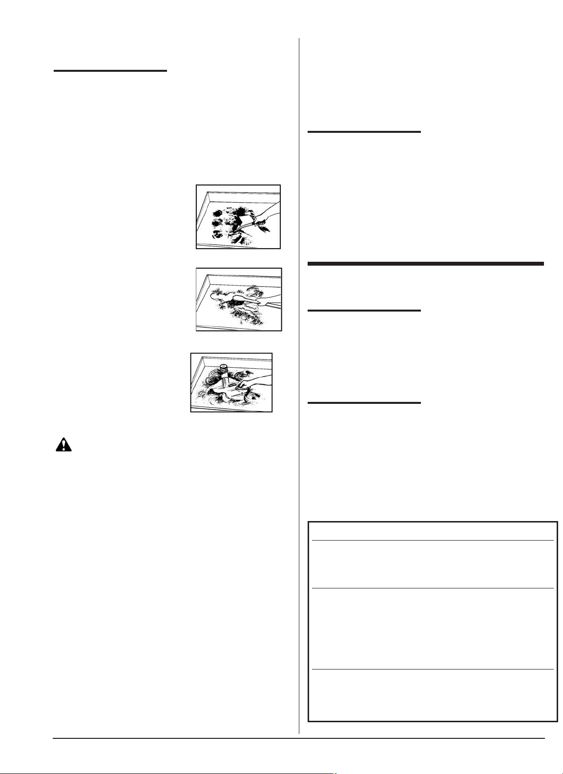
CAUTION: DO NOT HACK, CHOP, HIT OR
CUT ON THE MIRACLEAN® SURFACE. YOU WILL
DENT THE STEEL PLATE UNDER THE TRIVALENT
CHROME. IT IS EVEN POSSIBLE TO HACK TWO
NICKS CLOSE TOGETHER AND ACTUALLY TEAR
THE MIRACLEAN® SURFACE AS THE CHROMIUM
WILL NOT STRETCH. BELOW IS A SKETCH
SHOWING THE SIDE VIEW OF A GRIDDLE PLATE
AND HOW THE SURFACE CAN BE DAMAGED.
PROPER USE OF THE UTENSILS SUPPLIED WITH
YOUR MIRACLEAN® GRIDDLE WILL PREVENT
SURFACE DAMAGE.
Figure 3-4
Surface Damage
RECOMMENDED COOKING TEMPERATURE
PRODUCT (°F)
Eggs 250
Bacon 325
Sausage (patty or link) 325
Hash browns 350
French Toast 350
Wheat Cakes 360
Hamburgers- 2 / lb. (8 oz.) 325
4 / lb. (4 oz.) 315
10 / lb. (1.6 oz.) 310
Grilled Cheese 325
Chicken Breasts (skinless) 350
Hot Dogs- 10 / lb. (1.6 oz.) 310
8 / lb. (2 oz.) 310
Salmon Filet 325
Salmon Steaks 325
Buns/Breads (toasting) 375
30 seconds max.
RECOMMENDED COOKING TEMPERATURES
Load #1 Load #3 Load #2
396
285
174
“V”
Thermostat Bulb Location
Page 9
NOTE: Damage done to the MIRACLEAN® surface is
irreparable.
CLEANING THE
GRIDDLE
The surface of the MIRACLEAN® Griddle is very
durable and with proper care, following the procedures
below, will last many years.
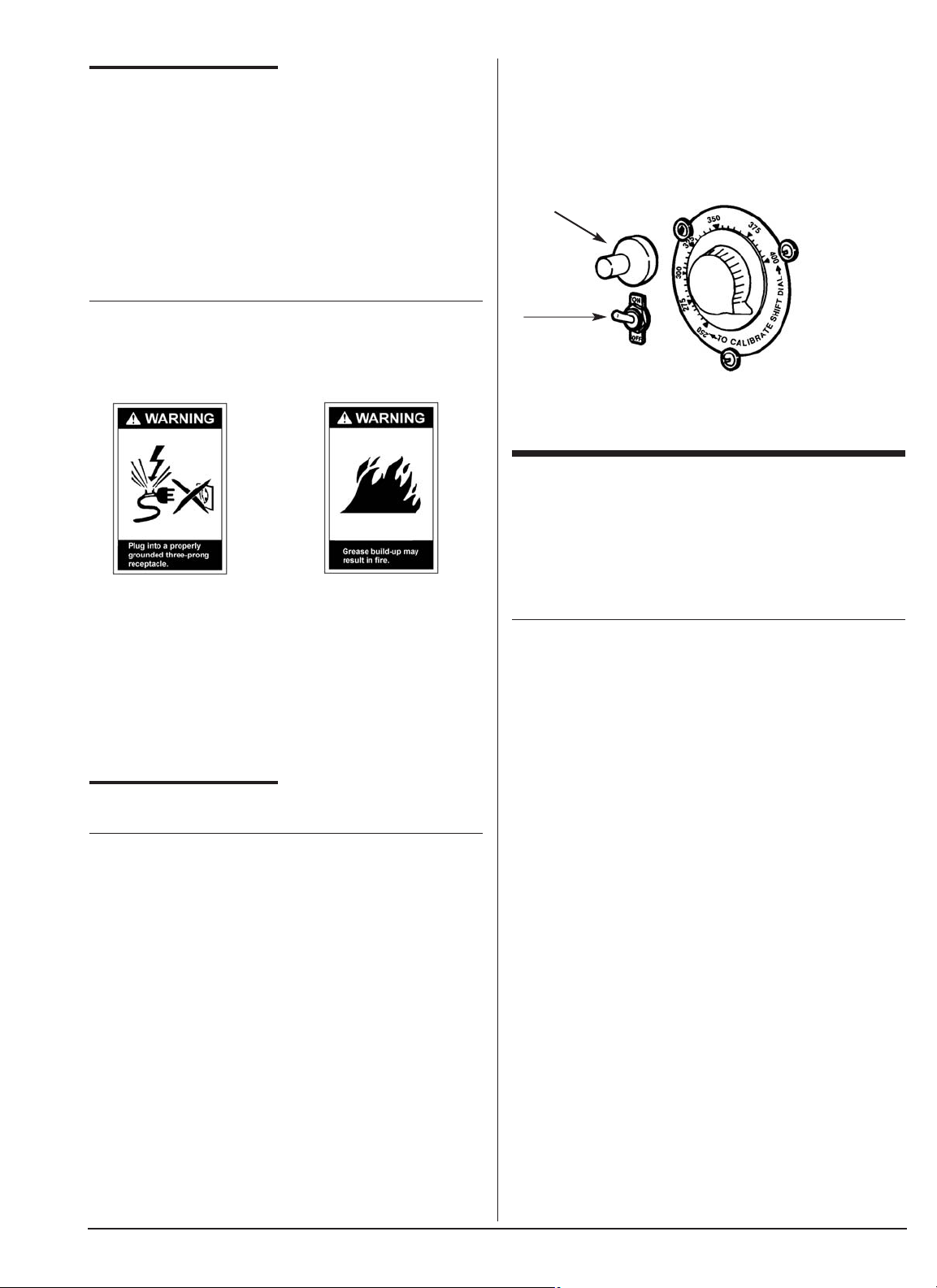
A sample of Keating Klenzer, Keating palmetto brush
and a 4” scraper are included with each new griddle.
1. Scrape MIRACLEAN®
surface.
2. Clean with potable tap water
and a Keating palmetto
brush.
3. Polish surface with
Keating Klenzer and a
soft cloth (towel).
Rinse with potable
water to remove
excess Keating
Klenzer.
WARNING
BECAUSE OF THE SUPERIOR MIRACLEAN®
SURFACE, THE ONLY TOOLS YOU WILL EVER
NEED TO CLEAN THE GRIDDLE ARE A NATURAL
BRISTLE BRUSH AND A KEATING SCRAPER.
NEVER USE GRIDDLE STONES, GRIDDLE
BRICKS, GRIDDLE SCREEN OR HARSH
CHEMICALS TO CLEAN THE MIRACLEAN®
SURFACE.
DAMAGE DONE TO THE MIRACLEAN®
SURFACE BY GRIDDLE STONE, GRIDDLE
BRICK, GRIDDLE SCREEN OR HARSH
CHEMICALS WILL VOID THE WARRANTY.
THE DAMAGE DONE TO THE MIRACLEAN®
SURFACE IS IRREPARABLE.
NEVER USE ICE TO COOL THE MIRACLEAN®
SURFACE. USE OF ICE MAY WARP THE
MIRACLEAN® SURFACE.
USE ONLY KEATING SUPPLIED CLEANING
TOOLS AND KLENZER.
USE ONLY A KEATING STEEL SPATULA.
DO NOT CLEAN SCRAPER ON SPLASHBACK,
GREASE BUILD-UP WILL OCCUR WHICH MAY
RESULT IN A FIRE.
DO NOT STORE ANYTHING IN OR ON THE FLUE
OF THE MIRACLEAN®.
SHUTDOWN
1. Turn ON/OFF switch to “OFF” position.
2. Turn gas valve knob to “OFF” position.
3. Check to determine that all burners, including pilot
light, are extinguished.
4. If you must restart your MIRACLEAN®, wait five
minutes before restarting or relighting with piezo
spark ignitor or a match.
IV MAINTENANCE
WARRANTY REPAIRS
Keating’s warranty begins with the date of installation.
In the event that your MIRACLEAN® Griddle, under
warranty, needs repairs other than routine
maintenance or cleaning, you are requested to contact
your local service distributor.
PREVENTIVE
MAINTENANCE
Preventive maintenance should be done in daily,
weekly, monthly and yearly intervals as necessary.
Following preventive maintenance procedures will help
keep your MIRACLEAN® working efficiently. Proper
care and servicing will lead to years of quality
performance.
PREVENTIVE MAINTENANCE CHART
6
*High production facilities should be checked more often.
TIME FRAME OPERATOR/OWNER SECTION
Daily
Clean griddle surface. III
Drain and clean grease drawer.
Completely wipe down griddle
cabinet.
Monthly* Check MIRACLEAN® surface III
to insure proper maintenance.
(Review proper cooking procedures)
Check calibration of IV
thermostat(s).
Review operating instructions II
received with griddle.
Yearly* QUALIFIED SERVICE PERSONNEL ONLY
Have griddle completely checked, calibrated, tested,
cleaned, etc. by qualified service personnel. Be sure to check
color and height of pilot flame.
Page 10
CLEANING
Proper care should be taken to fully clean the griddle
on a regular basis.
A. CONTROL PANEL – Clean any grease build-up on
switches and thermostat knobs.
IF ELECTRONIC IGNITION MODEL:
DISCONNECT ELECTRIC POWER SOURCE
BEFORE CLEANING. (REFER TO ELECTRONIC
IGNITION MANUAL)
NOTE: If grease gets into the working mechanism of a
switch or thermostat, it may cause the unit to fail.
B. CABINET - The front, back and sides of the cabinet
should be kept clean for sanitary reasons.
GREASE BUILD-UP NEAR ANY OPEN FLAME IS A
FIRE HAZARD.
C. FLUE - The flue has been designed specifically to
exhaust the by-product of any combustion. Any
objects (steak weights, egg covers, pans, rags,
utensils, etc.) placed on the flue will inhibit the proper
combustion and exhaust, therefore causing health
hazards.
LIMITED
CALIBRATION
NOTE: Calibration is not covered under warranty.
Tools: Accurate surface thermometer
Standard screwdriver
Calibrating screwdriver
1. Turn the exhaust system ON.
2. Turn on the griddle with thermostat set at 300°F.
Turn switches to ON positoin to allow burners to
cycle on and off three times. (Approximately 60
minutes.)
3. Place thermometer on surface over thermostat bulb.
Use the inverted “V” to locate thermostat bulb. See
Figure 3-3. When you have located the inverted “V”,
the thermostat bulb is approximately 2/3 to 3/4 of the
way straight back to the rear of the griddle.
4. When burners cycle off, griddle is up to temperature.
If temperature is within 25°F of thermostat setting,
loosen the four retaining screws on the dial plate.
Rotate the dial plate. Indicating arrow on the
thermostat knob should point to the temperature
indicated on the thermometer.
Piezo Spark Ignitor
“ON/OFF” Switch
5. Tighten screws.
For calibration over a 25°F difference, contact your
local service agent.
V SERVICE DIAGNOSIS
The following diagnosis is only to be used as a guide to
qualified service personnel. Keating recommends that
you use a qualified service company. (Equipment still
under warranty requires it.)
NOTE: To correctly and quickly diagnose the system,
the following chart should be followed in sequential
order.
7
Page 11
TROUBLE SHOOTING CHART
VI PARTS LIST
ORDERING PARTS
Parts may be ordered by part number by calling
Keating at 1-800-KEATING or your service company.
You may also order on-line at Keating’s part store,
www.keatingofchicago.com
Refer to the Keating MIRACLEAN® Griddle Limited
Warranty for complete service and ordering
information.
The model/serial plate is located on the front of the
control panel. The serial and model numbers are
necessary information when ordering.
WARNING AND
OPERATING PLATES
All warning and operating plates on the Keating
MIRACLEAN® Griddle should be in place at all times.
If plates are damaged or lost, replace them
immediately.
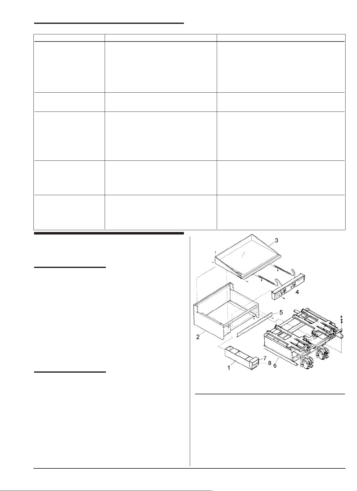
Figure 6-1 MIRACLEAN Griddle Assembly
ITEM DESCRIPTION PART NUMBER
1 GREASE DRAWER ASSEMBLY
24” DEEP GRIDDLES 004013
30”, 33”, AND 36” DEEP GRIDDLES 002446
2 CABINET REFERENCE ONLY
3 PLATE AND PERIMETER CALL 1-800-KEATING
4 CONTROL PANEL ASSEMBLY SEE PAGE 9
5 HEAT SHIELD CALL 1-800-KEATING
6 BURNER INSERT SEE PAGE 9
7 GREASE DRAWER FRONT WITH HANDLE 002446
8 GREASE DRAWER HANDLE 004542
8
PROBLEM PROBABLE CAUSE SOLUTION
No pilot a. Gas supply not “ON”. a. Open gas supply valve.
b. Air in gas lines. b. Press gas valve knob in “pilot” position
and hold.
c. Quick disconnect not tight. c. Tighten quick disconnect.
d. Gas valve is in “OFF” position. d. Turn valve knob to “pilot”.
e. Faulty Piezo Ignitor. e. Replace ignitor.
Pilot won’t stay on a. Loose thermopile. a. Tighten fitting and/or terminal leads.
b. Faulty thermopile. b. Replace thermopile.
Pilot on but no main a. ON/OFF switch is in “OFF” a. Put ON/OFF switch to “ON” position.
burner ignition position.
b. Gas valve is in “pilot” position. b. Turn knob to “ON” position.
c. Thermostat is not on. c. Turn thermostat to desired temperature.
d. Thermostat failure. d. Replace thermostat.
e. Gas valve failure. e. Replace valve.
Temperature of a. Thermostat is not calibrated. a. Calibrate thermostat.
griddle erratic b. Air from exhaust hood b. Have exhaust hood inspected.
excessive.
c. Improper cooking procedure. c. See ‘Cooking’, page 5.
Griddle stays hot or a. Thermostat is not calibrated. a. Calibrate thermostat.
overheats b. Thermostat failure. b. Replace thermostat.
c. Gas valve faulty. c. Replace gas valve.
d. Improper cooking procedure. d. See ‘Cooking’, page 5.
Page 12
9
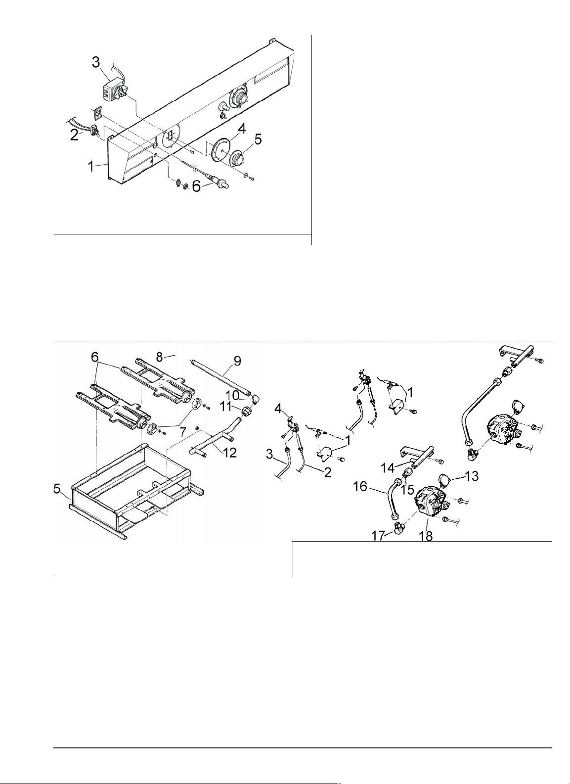
Figure 6-2 Control Panel Assembly
ITEM DESCRIPTION PART NUMBER
1 CONTROL PANEL CALL 1-800-KEATING
2 THERMOSTAT “ON/OFF”
SWITCH WITH WIRES 009345
3 THERMOSTAT 150°-550°F
MILLIVOLT W/ 14” CAP SHIELD 023897
REPLACEMENT KIT FOR 400°F +- STAT
150°-550°F MILLIVOLT 037088
4 THERMOSTAT DIAL PLATE 250°-400° 034870
THERMOSTAT DIAL PLATE “TO CALIBRATE” 012018
Figure 6-3 Natural and Propane Gas Heating Systems
ITEM DESCRIPTION PART NUMBER
1 SPARK IGNITION ASSEMBLY
SEE Item 6, Figure 6-2
2 THERMOPILE 022770
3 PILOT TUBE (1/4”) 007998
4 PILOT ASSEMBLY 029769 & 029599
(ALL NATURAL GAS, 24”-30”
LP, 24”-39” BEF)
NATURAL GAS ORIFICE 007696
PROPANE ORIFICE 007766
5 BURNER INSERT
REFERENCE ONLY
6 BURNER REFERENCE ONLY
7 AIR SHUTTERS 031477
8 MAIN SUPPLY GAS VALVE 3/4" 019515
(not shown above)
9 MAIN GAS PIPE (3/4”) REFERENCE ONLY
10 STREET ELBOW (3/4”) 005738
11 UNION 002658
12 MANIFOLD 1-800-KEATING
13 STREET ELBOW (1/2”) 004194
14 ORIFICE HOLDER
ASSEMBLY
REFERENCE ONLY
15 FITTING (IF ELBOW) 006477
FITTING (IF STRAIGHT) 006473
16 BURNER TUBE (1/2”
X 9”) 1-800-KEATING
17 ELBOW (1/2” x 3/8”) 002462
STRAIGHT 000615
18 GAS VALVE, MILLIVOLT
NATURAL GAS 023625
PROPANE GAS 023624
5 THERMOSTAT KNOB 400° 004163
THERMOSTAT KNOB 550° 002615
6 PIEZO SPARK IGNITOR ASSEMBLY
A. MOUNTED ON LEFT, 45°
BRACKET. USED ON ALLNATURAL GAS
STANDARD GRIDDLES AS WELL AS 27” AND
30” LEFT SIDE ON SINGLE BURNER
PROPANE GRIDDLES. 010946
B. MOUNTED ON RIGHT.
45° BRACKET. USED ON BEF 36” & 27: AND
30” RIGHT SIDE GRIDDLES. 002556
C. CENTER MOUNT. 90°
BRACKET. USED ON ALL PROPANE
GRIDDLES WITH MORE THAN TWO
BURNERS (42”AND UP). FOR BAT WING
PILOT. 010365
D. NO MOUNTING BRACKET. USED ON
PROPANE GRIDDLES with 2 or less burners
24”, 27”, 30”, 36” ON RIGHT SIDE. 008327
E. NO MOUNTING BRACKET. MOUNTS ON
PILOT BRACKET 010364
Page 13
10
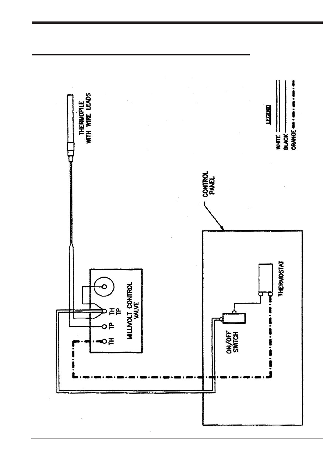
SECTION VII WIRING DIAGRAM
GAS GRIDDLE WIRING DIAGRAM
Page 14
L
IMITED
W
ARRANTY
Keating Of Chicago, Inc. ("Keating”) warrants to the original purchaser. ("Customer"), all new Keating Fryers, Filter Systems,
Griddles, Keep Krisp®, Custom Pasta Systems, Top-Side™ Cookers, Computer Timers, Fryer & Pasta Vessels, and
Keating replacement parts ("products") installed after June 1, 1994 to be free to defects in material or workmanship, subject t
o the following terms and conditions.
L
ENGTH
O
F
W
ARRANTY
All products other than Fryer & Pasta Vessels and replacement parts shall be warranted for a period of one year from the date o
f original equipment installation. Keating replacement parts are warranted for a period of ninety days from the date
of installation. Fryer & Pasta Vessels are warranted as described below.
F
RYER
& P
ASTA
V
ESSEL
W
ARRANTY
Fryers purchased after June 1, 1994 carry a prorated vessel warranty on defects in materials or workmanship to the Customer bas
ed on the following scale:
Time from Installation Date Fryer Vessel Warranty Credit
13-60 months 100%
61-72 months 80%
73-84 months 60%
85-96 months 40%
97-108 months 20%
109-120 months 10%
The credit for the defective fryer & pasta vessel shall be applied against the cost of the replacement vessel, utilizing Keatin
g's then current price, upon return of the vessel to Keating, (freight to be paid by Keating within the first 2 months only),
only during the first 60 months, subject to the limitations described below.
L
IMITATIONS
O
F
L
IABILITY
In the event of warranty claim or otherwise, the sole obligation of Keating shall be the repair and/or replacement at the optio
n of Keating of the product or component or part thereof. Such repair or replacement shall be at the expense of Keating
except that the Customer shall pay the following expenses: all freight and labor expense for Keating replacement parts; for all
other products, mileage exceeding 50 miles or travel more than one hour, labor costs of more than one person, overtime
rates, truck charges, difference between ground and other mode of transportation, and holiday charges. Any repair or replacemen
t under this Limited Warranty does not constitute an extension of the original warranty for any period for the product
or for any component or part thereof. Parts to be replaced under this Limited Warranty will be repaired at the option of Keatin
g with new or functionally operative parts. Keep Krisps and Computer Timers must be returned to Keating for warranty
repair or replacement. Field repairs of those items are not authorized.
THE LIABILITY OF KEATING ON ANY CLAIM OF ANY KIND, INCLUDING CLAIMS BASED ON WARRANTY, EXPRESSED OR IMPLIED, CONTRACT, NEGLIGEN
CE, STRICT LIABILITY OR ANY OTHER THEORIES
SHALL BE SOLELY AND EXCLUSIVELY THE REPAIR OR REPLACEMENT OF THE PRODUCT AS STATED HEREIN, AND SUCH LIABILITY SHALL NOT INCLUDE
, AND CUSTOMER SPECIFICALLY RENOUNCES ANY
RIGHTS TO RECOVER, SPECIAL, INCIDENTAL, CONSEQUENTIAL OR OTHER INJURIES TO PERSONS OR DAMAGE TO PROPERTY, LOSS OF PROFITS OR A
NTICIPATED PROFITS, OR LOSS OF USE OF THE PRODUCT.
If any oral statements have been made regarding the Keating products, such statements do not constitute warranties and are not
part of the contract sale. This Limited Warranty constitutes the complete, final and exclusive statement with regard
to warranties.
THIS LIMITED WARRANTY IS EXCLUSIVE AND IS IN LIEU OF ALL OTHER WARRANTIES WHETHER WRITTEN, ORAL, STATUTORY OR IMPLIED, INCLUDIN
G BUT NOT LIMITED TO ANY WARRANTY OF
MERCHANTABILITY OR FITNESS FOR PARTICULAR PURPOSE OR WARRANTY AGAINST LATENT DEFECTS.
E
XCLUSIONS
The warranties provided by Keating of Chicago, Inc. do not apply in the following instances:
1. Defects arising out of or resulting from improper installation or maintenance, abuse, misuse, modification or alteration by u
nauthorized service personnel, or any other condition not attributable to a defect in material or
workmanship. Proper installation and maintenance are the responsibility of the installer and Customer, respectively. Proper ins
tallation and maintenance procedures are prescribed by the Keating Service Manual.
2. In the event that the product was damaged after leaving the factory due to flood, fire, other acts of God or accident, damage
during shipment should be reported to the carrier and is not the responsibility of Keating.
3. In the event the serial number or rating plate has been removed from the product or altered.
4. On parts which would normally be worn or replaced under normal conditions, including but not limited to electric bulbs, fuses
, interior and exterior finishes, gaskets and radiants.
5. With regard to adjustments and calibrations such as leveling, tightening of fasteners or plumbing connections, improper gas p
ressure or improper electrical supply, the checking of and changes in adjustment and
calibrations are the responsibility of the installer. Proper installation procedures are prescribed by the Keating Service Manu
al.
6. In the event of unauthorized repairs or alterations to the Keating product.
7. With the use of sodium chloride in pasta vessels or harsh chemicals in fryer or pasta vessels.
8. Installation in Household.
O
THER
T
ERMS AND
C
ONDITIONS
The Customer must provide proof of purchase from Keating.
This Limited Warranty is valid in the 50 United States, its territories, and Canada, and is void elsewhere.
Keating products are sold for commercial use only. If any Keating product is sold as a component of another product or used as
a consumer product, such Keating product is sold As Is without any warranty.
If any provision of this Limited Warranty is held to be unenforceable under the law of any jurisdiction, such provision shall b
e inapplicable in such jurisdiction, and the remainder of the warranty shall remain unaffected. Further in such event,
the maximum exclusion or limitation allowable under applicable law shall be deemed substituted for the unenforceable provision.
This Limited Warranty shall be governed by and construed in accordance with the laws of the State of Illinois.
T
O
S
ECURE
W
ARRANTY
S
ERVICE
All repair services under this Limited Warranty must be authorized by Keating or performed at Keating. Authorization may be obt
ained by calling 1-800-KEATING within the Continental United States, Alaska, Hawaii, Puerto Rico and Canada
during normal business hours (8 a.m. through 5 p.m. Central Time, Monday through Friday). When calling, please have the followi
ng information available: (1) name, address and
telephone number of the Customer; (2) location of product, if different; (3) name, model number and serial number of the produc
t; (4) installation date; and (5) description of defect. Keating will then issue a service authorization work order
number to one of its approved independent servicing organizations, or request the product or part be shipped to Keating for rep
air or replacement, as appropriate. Any defective part subject to a claim under this Limited Warranty must be shipped
freight prepaid to Keating for testing and examination. Keating's decision as to the cause and nature of any defect under this
Limited Warranty shall be final.
K
EATING
K
EATING OF
C
HICAGO
, I
NC
., 1-800-KEATING,
WWW
.KEATINGOFCHICAGO
.
COM
REFILE/warranty 3/09
WARRANTY
Page 15

KEATING LIMITED WARRANTY CARD
PLEASE COMPLETE AND MAIL AT ONCE–WARRANTY IS NOT IN EFFECT UNTIL CARD IS RETURNED.
WARRANTY CARD IS ALSO AVAILABLE TO COMPLETE ON LINE AT YOUR CONVENIENCE.
COMPANY: ______________________________________________________________________________________________________________
ADDRESS: ______________________________________________________________________________________________________________
CITY: ____________________________________________________________________ STATE:________________ ZIP: __________________
DEALER:________________________________________________________________________________________________________________
DATE OF PURCHASE:__________________________________________________________ INVOICE NUMBER:__________________________
SERIAL NUMBER: ____________________________________ FRYER FILTER SYSTEM GRIDDLE
REMARKS:__________________________________________ TOP-SIDE COOKER HOT PLATE PASTA PLUS
I HAVE READ THE INSTALLATION AND OPERATION INSTRUCTIONS.
SIGNED: __________________________________________________________________________ DATE: ______________________________
GasGrid pre2000
9/07
SERVICE INFORMATION
If you have a service related question call 1-800-KEATING.
Please state the nature of the call; it will ensure speaking with the appropriate person.
Have your serial and model number available when ordering parts.
KEATING OF CHICAGO, INC.
Phone: (708) 246-3000 FAX: (708) 246-3100
Toll Free 1-800-KEATING (In U.S. and Canada)
www.keatingofchicago.com
*As continuous product improvement occurs, specifications may be changed without notice.
 Loading...