

Keating Of Chicago 2009 User Manual

1-800-KEATING
www.keatingofchicago.com
Users Manual
CUSTOM PASTA®SYSTEM ELECTRIC
SERIES 2009
READ AND SAVE THIS MANUAL FOR FUTURE REFERENCE.
Keep this manual for training new personnel.
SECTION I: I NTRODUCTION . . . . . . . . . . .. . . . . . . . . . . . . . 1
SECTION II: INSTALLATION
SHIPMENT AND TRANSIT . . . . . . . . . . . . . . . . . . . . . . . . . . . . . . . . .3
INSTALLATION . . . . . . . . . . . . . . . . . . . . . . . . . . . . . . . . . . . . . . . . . . . .3
A. POSITIONING, LEVELING, & RESTRAINING DEVICES . . . . .4
B. ELECTRICAL CONNECTION . . . . . . . . . . . . . . . . . . . . . . . . . . . .4
C. WATER & DRAIN CONNECTION . . . . . . . . . . . . . . . . . . . . . . . .4
SECTION I II: OPE RATION
FILLING . . . . . . . . . . . . . . . . . . . . . . . . . . . . . . . . . . . . . . . . . . . . . . . . .5
THERMOSTATS . . . . . . . . . . . . . . . . . . . . . . . . . . . . . . . . . . . . . . . . . . .5
CONTROL PANEL FEATURES . . . . . . . . . . . . . . . . . . . . . . . . . . . . . .5
THE AUTO-FILL SYSTEM . . . . . . . . . . . . . . . . . . . . . . . . . . . . . . . . . . .5
COOKING . . . . . . . . . . . . . . . . . . . . . . . . . . . . . . . . . . . . . . . . . . . . .5-6
DRAINING & CLEANING . . . . . . . . . . . . . . . . . . . . . . . . . . . . . . . . .6-7
ELECTRONIC (DIGITAL) TIMERS . . . . . . . . . . . . . . . . . . . . . . . . .7-8
SECTION IV: MAI NTENANCE
WARRANTY REPAIRS . . . . . . . . . . . . . . . . . . . . . . . . . . . . . . . . . . . . .8
PREVENTIVE MAINTENANCE . . . . . . . . . . . . . . . . . . . . . . . . . . . . . .8
CALIBRATION . . . . . . . . . . . . . . . . . . . . . . . . . . . . . . . . . . . . . . . . . .8-9
AUTO-FILL & SAFETY SHUT OFF . . . . . . . . . . . . . . . . . . . . . . . . . . .9
SENSOR TUBE CLEANING . . . . . . . . . . . . . . . . . . . . . . . . . . . . . . . .9
SECTION V: SERVICE DIAGNOSIS
AUTO-FILL SYSTEM . . . . . . . . . . . . . . . . . . . . . . . . . . . . . . . . . . . . . .10
COOKER HEATING SECTION . . . . . . . . . . . . . . . . . . . . . . . . . . . .10
TROUBLESHOOTING CHARTS . . . . . . . . . . . . . . . . . . . . . . . .11-12
SECTION VI: PARTS LIST
ORDERING PARTS . . . . . . . . . . . . . . . . . . . . . . . . . . . . . . . . . . . . . .13
CONTROL PANEL ASSEMBLY . . . . . . . . . . . . . . . . . . . . . . . . . . . .13
PARTS LIST . . . . . . . . . . . . . . . . . . . . . . . . . . . . . . . . . . . . . . . . . . . . .14
SECTION VI I: WIR ING DIAGRAM S
14" ELECTRIC PASTA WITHOUT TIMERS . . . . . . . . . . . . . . . . . .15
14” ELECTRIC PASTA WITH DIGITAL TIMERS . . . . . . . . . . . . . .16
14" ELECTRIC PASTA WITH 138 (BLACK DIAL) TIMERS . . . .17
14” ELECTRIC PASTA WITH
BASKET-LIFT & DIGITAL TIMERS . . . . . . . . . . . . . . . . . . . . . . . . . .18
18" & 20" ELECTRIC PASTA WITH
(BLACK DIAL) 138 TIMERS . . . . . . . . . . . . . . . . . . . . . . . . . . . . . . .19
18" ELECTRIC PASTA, 2-THERMOSTATS
WITHOUT TIMERS . . . . . . . . . . . . . . . . . . . . . . . . . . . . . . . . . . . . . .20
24” ELECTRIC PASTA WITH DIGITAL TIMERS . . . . . . . . . . . . . .21
WARRANTY
KEATING WARRANTY . . . . . . . . . . . . . . . . . . . . . . . . . . . . . . . . . . . .22
CONTENTS:
IMPORTANT:
Keep a copy of your bill of sale. The date on the bill establishes the warranty period
should service be required. If service is performed, it is in your interest to obtain and keep all receipts.
Keating Custom Pasta Systems
®
are not intended for household use.
This Owner’s Guide provides specific operating and service instructions for your model. Use the
Custom Pasta Systems
®
only as instructed in this Service Manual.
PastaElectric
03/11
part# 024763
RECORD THE MODEL AND SERIAL
NUMBERS OF THIS CUSTOM PASTA
®
SYSTEM IN THE SPACES PROVIDED.
SERIAL NO. ______________________________
MODE L NO. _____________________________
KEEP THESE NUMBERS FOR FUTURE RE FER ENCE.
i
This operating, installation, and service manual should be given to
the user. The operator of the Custom Pasta
™
System should be
familiar with the functions and operation of the cooker. This manual
must be kept in a prominent, easily reachable location near the Pasta
System.
POST THIS LABEL IN A
PROMINENT LOCATION ON
YOUR UNIT
Using any parts other than genuine, Keating of Chicago, Inc. factory
manufactured part relieves the manufacturer of all warrant and liability.
Keating of Chicago, Inc. manufacturer reserves the right to change
specifications at any time.
IMPROPER INSTALLATION, ADJUSTMENT,
ALTERATION, SERVICE OR MAINTENANCE
CAN CAUSE PROPERTY DAMAGE, INJURY OR
DEATH. READ THE INSTALLATION, OPERATING
AND MAINTENANCE INSTRUCTIONS
THOROUGHLY BEFORE INSTALLING OR
SERVICING THIS EQUIPMENT.
FOR YOUR SAFETY
DO NOT STORE OR USE GASOLINE OR
OTHER FLAMMABLE VAPORS AND LIQUIDS
IN THE VICINITY OF THIS OR ANY OTHER
APPLIANCE.
WARNING
Improper installation
can cause damage,
injury or death.
ShockBurnsGas
WARNING
Do not store flammable
liquids near this or any
other appliance.
1
I INTRODUCTION
Instructions in this manual should be read thoroughly
before attempting to operate this Keating Electric
Pasta Cooker. All installation and service on Keating
Equipment must be performed by qualified, certified,
licensed and/or authorized installation or service
personnel.
Operating information for Keating equipment has
been prepared for use by qualified and/or authorized
personnel.
Keating equipment is made in the U.S.A. and has
American sizes of hardware. All meteric conversions
are approximate.
GENERAL
Keating Electric Custom Pasta™Systems are designed
to give maximum production efficiency, delivering high
quality food products. The following design features are
incorporated in Keating Pasta Electric Systems.
STANDARD FEATURES
• Highly polished stainless steel vessel
• Highly polished stainless steel front
• Highly polished stainless steel elements
• Highly polished stainless steel thermostat bulb
• Highly polished stainless steel Hi-Limit sensor
• Grid screen over elements
• Automatic water fill with manual override
• Water solenoid and indicating light
• Starch overflow
• Two electronic timers
• Low water safety shutoff
• 1" full port front drain valve on 14;
1
1
/4" for 18 and larger
• High temperature limit control with manual reset
• Patented accurate temperature control system
±2°F
• Ideal 35" working height
• One pair of perforated split baskets or one bulk
basket
• Patented dual thermostat system
• Indicating lights for pilot and secondary thermostat
on
STANDARD ACCESSORIES
• Keating Klenzer Sample
• Drain clean out rod
• Sensor Cleaning Brush
STANDARD PASTA SYSTEMS
• Sizes: 14” to 24”
• Water capacity 51/2 to 24 gallons
• 24” Pasta System can cook 6 lbs. of dry pasta per
load up to 110 lbs. per hour
• NSF certified
• ETL Certified listed
• ETL Sanitation Certified listed
MODEL VARIATIONS
Basket-Lift Model: Basket-Lift Model Pasta Systems
come with all the same features as the standard
models. The Basket-Lift mechanism lowers the baskets
of food into the water when the timer button is pressed
and raises the baskets when the cooking cycle is
complete. Split baskets are required for these models.
SPECIFICATIONS
MODEL kW @ 240V
AMPS
SHIP WT.
3P 1P
14 15.5 32-56-32 65 140 lbs
18 21.4 52-52-52 89 215 lbs.
20 21.4 52-52-52 89 235 lbs.
24 28.6 79-79-52 119 285 lbs.
MODEL CAPACITY HEIGHT DEPTH WIDTH
14 7 gal. 461/2" 311/8" 153/8"
18 10 gal. 461/2
"
331/8
"
193/8
"
20 17 gal. 461/2" 351/8" 213/8"
24 24 gal. 461/2" 391/8" 253/8"
SAFETY
PRECAUTIONS
THIS SYMBOL WARNS YOU THAT SERIOUS BURNS
OR OTHER INJURIES MAY RESULT IF SAFETY
INSTRUCTIONS ARE NOT FOLLOWED.
• This service manual should be retained in a safe
place for future reference. The installation of your
new Pasta System must conform to local codes
and with the current National Electrical Codes and
regulations as applicable.
• Your ventilation hood, when installed, must
conform to the current standards.
• No frame or restriction shall be constructed around
the Custom Pasta System that will restrict air
movement into the Pasta System or prevent
proper ventilation.
• You must maintain this appliance free and clear
from combustibles.
• Adequate clearance for servicing and proper
operation must be maintained. Your pasta system
is designed to be serviced from the front.
• Keating Custom Pasta
™
Systems are not intended
for household use. Installation in household voids
warranty.
• ALWAYS instruct new employees on proper pasta
system operation.
• A Custom Pasta System™should be operated
ONLY by properly trained personnel.
• ALWAYS turn pasta system off each night.
• ALWAYS turn pasta system off at customer power
panel before servicing.
• NEVER leave a pasta system unattended during
operation.
• NEVER move a pasta system when full of hot
water.
• NEVER introduce objects or liquids into pasta
system, while operational, which are not designed
or made for cooking.
• THIS CUSTOM PASTA™SYSTEM MAY NOT BE
ALTERED, MODIFIED OR CHANGED IN ANY
WAY.
IF THE EQUIPMENT IS NOT
INSTALLED, OPERATED AND
MAINTAINED IN ACCORDANCE
WITH THE ABOVE,
CONCENTRATIONS OF CARBON
MONOXIDE IN EXCESS OF THE
ESTABLISHED LIMITS COULD BE
PRESENT IN THE KITCHEN
ENVIRONMENT.
ALL PERSONNEL IN THE WORK PLACE WHO MAY
BE SUBJECT TO ANY EXPOSURE OF CARBON
MONOXIDE MUST BE WARNED OF SUCH
POSSIBLE EXPOSURE. THIS WARNING SHOULD
BE CONVEYED IN A MANNER SO THAT IT IS
CLEARLY UNDERSTOOD BY THE EMPLOYEE, AND
THE EMPLOYEE SHOULD BE ASKED IF IN FACT HE
OR SHE UNDERSTANDS THE CORRECT METHOD
OF OPERATION OF THE EQUIPMENT AND THAT A
RISK OF EXPOSURE EXISTS IF THE EQUIPMENT
IS OPERATED IMPROPERLY.
IF NOT INSTALLED, OPERATED AND MAINTAINED
IN ACCORDANCE WITH THE MANUFACTURER’S
INSTRUCTIONS, THIS PRODUCT COULD EXPOSE
YOU TO SUBSTANCES IN FUEL OR IN FUEL
COMBUSTION WHICH CAN CAUSE DEATH OR
SERIOUS ILLNESS AND WHICH ARE KNOWN TO
THE STATE OF CALIFORNIA TO CAUSE CANCER,
BIRTH DEFECTS OR OTHER REPRODUCTIVE
HARM.
2
WARNING
Improper installation
can cause damage,
injury or death.
ShockBurnsGas
3
II INSTALLATION
This Custom Pasta™System MUST
be installed, inspected, calibrated
and serviced by qualified and/or
certified and/or licensed service
personnel – you may void your
Keating warranty if installation is not
completed per current local, national
and Keating specifications. Contact
your dealer for assistance.
DAMAGE DURING
SHIPMENT
The Custom Pasta™System has been assembled,
tested and inspected at the factory. Upon arrival, the
complete Pasta System should be checked for any
damage that may have occurred during shipment.
IF EQUIPMENT ARRIVES DAMAGED
Keating does not assume responsibility for loss or
damage incurred in transit.
IMPORTANT
This merchandise has been thoroughly inspected and
carefully packed before leaving our plant. Responsibility
for its safe delivery was assumed by the carrier at the
time of shipment. Claims for loss or damage to the
contents should, therefore, be made upon the carrier,
as follows:
CONCEALED LOSS OR DAMAGE
Concealed loss or damage means loss or damage
which does not become apparent until the merchandise
has been unpacked. The contents may be damaged in
transit due to rough handling even though the carton
may not show external damage. When the damage is
discovered upon unpacking, make a written request for
inspection by the carrier’s agent within fifteen days of
the delivery date. Then file a claim with the carrier since
such damage is the carrier’s responsibility. By following
these instructions carefully, we guarantee our full
support of your claims to protect you against loss from
concealed damage.
VISIBLE LOSS OR DAMAGE
Any external evidence of loss or damage must be noted
on the freight bill or express receipt, and signed by the
carrier’s agent. Failure to adequately describe such
external evidence of loss or damage may result in the
carrier refusing to honor a damage claim. The form
required to file such a claim will be supplied by the
carrier.
DO NOT RETURN DAMAGED MERCHANDISE TO
KEATING. FILE YOUR CLAIM AS ABOVE.
IT MAY BE NECESSARY TO INSTALL A BACK FLOW
OR CHECK VALVE ON THE WATER SUPPLY LINE
TO THE PASTA COOKER. CHECK WITH EITHER
YOUR LOCAL WATER OR HEALTH DEPARTMENT
TO DETERMINE IF THIS IS NECESSARY IN YOUR
SPECIFIC AREA.
DROP-IN PASTA COUNTER
CUTOUT/INSTALLATION
INSTALLATION NOTES
1. Minimum of 130 sq. in. unobstructed vent area near
pasta cooker required for combustion.
2. All Drop-In Pasta must be 16” from any open flame.
3. Pasta must be located no more than 5” from counter
top front.
4. Cabinet must be reinforced to support full weight of
past in use (pasta, water, food, etc.).
5. Pasta cooker must be properly ventilated and located
under an exhaust hood.
DROPPING THE PASTA COOKER INTO THE
It is only necessary to place the pasta cooker in such a
position that the front edge overlaps the front raised
edge of the opening.
COUNTER TOP
WARNING
Improper installation
can cause damage,
injury or death.
ShockBurnsGas
4
Push the fryer forward as far as it will go holding the
fryer on approximately a 15° angle, and then drop the
rear of the pasta cooker into its proper position lowering
it down gently so you do not deform the table or
equipment stand.
POSITIONING
The pasta cooker must be no closer than 6" from any
combustible material. When placed under an exhaust
hood with a fire retardant system it must comply with
ANSI/UL 507-(Latest Edition) and ANSI/NFPA 96(Latest Edition). No frame or restriction can be
constructed around the lower part of the pasta cooker
that would restrict ventilation or air movement into the
pasta cooker. You must insure adequate air supply to
the pasta cooker.
Adequate clearance for servicing and proper operation
must be maintained. Your pasta cooker is designed to
be serviced from the front. Do not place a pasta cooker
next to a deep fat fryer. Hot oil and water can cause an
unstable condition creating a hazardous situation.
LEVELING
The Pasta System will operate at its highest efficiency
when properly leveled. Place a level on Pasta System
vessel from side to side. For Pasta Systems on legs, the
bottom foot of the leg is adjustable. Turn counter
clockwise to decrease height or clockwise to increase
height until level. For Pasta Systems on casters, the
casters are adjustable by loosening the jam nut and
turning the caster in or out. When the desired level is
reached, tighten the jam nut. Adjustments of more than
3
/4" are not recommended on any caster. The same
procedure should be followed to level the Pasta System
from front to back.
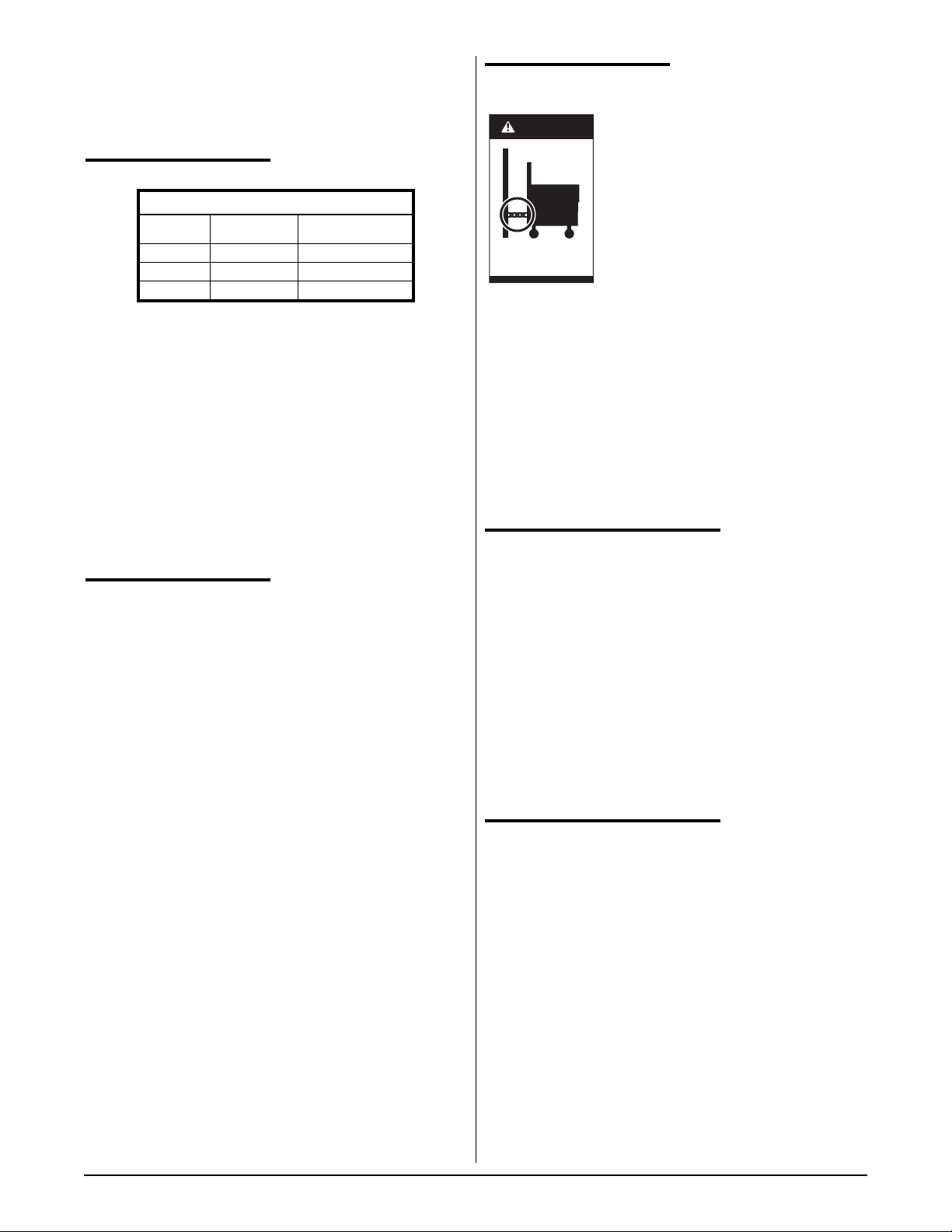
Figure 2-1
RESTRAINING
DEVICES
On Custom Pasta
™
System
installations with casters, casters and
jam nuts must be completely
tightened. Adequate means must also
be provided to limit the movement of
the appliance without depending on
the connector, the quick-disconnect
device or its associated piping to limit
the appliance movement.
Connectors must comply with ANSI Z21.69/CAN1
CAN/CGA 6.16 (latest edition) for connectors for
movable gas appliances. Quick-disconnect devices
must comply with ANSI Z21.41/CAN 1 6.9 (or latest
edition) standard for quick-disconnect devices for use
with gas fuel as applicable.
IF DISCONNECTION OF THE RESTRAINT IS
NECESSARY, IT MUST BE RECONNECTED WHEN
THE CUSTOM PASTA
™
SYSTEM IS RETURNED TO
ITS ORIGINALLY INSTALLED POSITION.
ELECTRICAL CONNECTION
Your pasta cooker has been ordered in either 1 phase
or 3 phase by your dealer. All electrical connections
should be made by a licensed electrician. If necessary
this unit can be field changed from 1 phase to 3 phase
or from 3 phase to 1 phase. Have a qualified electrician
refer to the wiring diagram.
ALL ELECTRICAL WIRING LEADING TO THE PASTA
COOKER MUST CONFORM TO LOCAL CODES. BE
SURE THE ON/OFF SWITCH IS IN THE OFF
POSITION BEFORE TURNING THE POWER ON TO
THE PASTA COOKER.
WATER AND DRAIN CONNECTION
The water is to be connected to the 3/8" female pipe
connection on the cabinet back, for auto-fill and the
optional faucet.
Make sure this and all other connections do not leak.
Check your water pressure. The auto-fill system is not
designed to handle pressure greater than 60 psi. Any
pressure greater than this can damage the auto-fill
solenoid or cause the system to fail. If the pressure is
greater than 60 psi a pressure regulator should be
added. The water temperature must not exceed 150°F
(65.6°C). Hot or warm water is not needed due to the
instant recovery of the Custom Pasta™System.
If during operation the boil is killed when water
automatically enters the pasta cooker, turn the water
pressure down until the water is added without killing
the boil. The drain terminates within inches of the floor
and is designed for the standard dump to drain opening.
CLEARANCES
Combustible
Construction
Non-Combustible
Construction
Back 6" 0"
Right Side 6" 0"
Left Side 6" 0"
Caster
Leg
NOTICE
Restraining devices
required.

5
In most cases the health department will not allow a
direct connection between the cooker drain and the
floor receptical. Contact your local health department for
specific information in your area.
III OPERATION
FILLING
NOTE: Before filling the Pasta System make certain the
vessel is sanitized, dry and the drain valve is completely
closed.
Figure 3-1
Manual Water Fill Level
When the water fill toggle switch (located between the
green and blue indicating lights) is turned on, the Pasta
System vessel automatically will be filled to the proper
level. If the vessel is being manually filled with water
from a faucet or through the manual fill button, fill to just
below the overflow deck. The black manual fill button is
located to the right of the blue water fill indicating light.
THERMOSTATS
The Keating pasta cooker has two thermostats. This is
to allow maximum control of the boil. The system is
designed so that both thermostats will function together
when called for but one thermostat will act as primary
and hold the water at a rolling boil during cooking as
well as idle time. The two thermostats allow the user to
have complete control over the cooking process.
The right side thermostat will only activate if the left side
thermostat is active. From a cold start all elements and
thermostats will be on and heat the water to a rolling
boil. Once the water has reached a rolling boil the right
side (secondary) thermostat will turn off and the left side
thermostat (primary) will hold the water at a rolling boil.
When product to be cooked is dropped into the pasta
cooker the drop in temperature depends on the
temperature spread between the two thermostats as
determined by the user.
If adding product does not turn on the secondary
thermostat and the water falls below a rolling boil,
increase the setting slightly on the secondary
thermostat. It is not recommended that there be less
than a twenty degree difference between the two
thermostats. Having less than a twenty degree
difference will increase the possibility of a boil over and
cause the pasta cooker to short cycle. The
recommended starting temperatures for the cooker are
212°F (98.8°C) for the primary and 190°F (87.8°C) for
the secondary thermostat. Using these settings with the
knowledge of the operation of this system, the user can
fine tune the settings to fit his specific operation.
CONTROL PANEL FEATURES
Figure 3-2
Custom Pasta System Electric Control Panel
AMBER–shows the power is on.
GREEN–shows the secondary (right)
thermostat is calling for heat from the
center element(s).
BLUE–shows water is filling into the
Pasta System vessel through the Pasta
System water solenoid valve.
NOTE: The black manual water fill button is located to
the right of the blue indicating light.
THE AUTO-FILL SYSTEM
The water temperature must not exceed 120°F (48.8°C).
Control of the water level is fully automatic with the auto-fill
system. The water level is controlled by two circuit boards
attached to the two water level sensors located on the front
of the pot below the spashdeck. Once the water switch is
turned to ON, the pasta cooker will start to fill with water.
The heating elements will not turn on until the water level is
above the bottom sensor. This is an automatic water safety
built into every pasta cooker. This safety prevents the pasta
cooker from accidental heat damage due to low or no water.
The bottom sensor is the low water cut off. The top sensor
is the water level control. Both sensors should be cleaned
on a regular basis to prevent water deposits from interfering
with the sensor reaction. Cleaning should be done with the
brush up and down the sensor tube located on the right side
of the splashdeck.
COOKING
Keating Electric Custom Pasta Systems are designed to
provide maximum production efficiency and deliver high
quality food products. Low-temperature cooking and highly
polished stainless steel mean greater energy savings. Two
thermostats are used to provide instant recovery and to
save energy while water is boiling. The secondary (right)

6
thermostat calls for additional heat at start up or
occasionally when water is added. Follow cooking
procedures below for your model.
NOTE: Use of sodium chloride during the cooking
process will have a detrimental effect on the cooker tank
and will void the warranty.
OPERATION OF THIS PASTA SYSTEM SHOULD
BE LIMITED TO PERSONNEL WHO HAVE BEEN
THOROUGHLY TRAINED IN OPERATING
PROCEDURES.
USE ONLY KEATING APPROVED BASKETS IN
YOUR PASTA SYSTEM. NEVER OVERFILL
BASKETS. DO NOT BANG BASKETS ON
BASKET HANGERS OR PASTA SYSTEM
VESSEL.
CARE SHOULD BE TAKEN WHEN LOWERING
BASKETS INTO PASTA SYSTEM TO PREVENT
SPLASHING HOT WATER FROM PASTA
SYSTEM VESSEL.
NEVER LIFT BASKETS DIRECTLY OUT OF THE
PASTA SYSTEM VESSEL WITHOUT DRAINING
AS SEVERE INJURY MAY RESULT.
NOTE: For counter model Pasta Systems, always
check the rear drain operating handle before attempting
to use the Pasta System. A safety switch prevents the
Pasta System from operating if the handle is not pushed
in completely and latched.
A. Standard Pasta System
1. Fill Pasta System as described on page 6 –
Filling.
2. Set primary (left) thermostat to 212°F(100°C)
and secondary (right) thermostat to
190°F(87.8°C).
3. When the water starts boiling, lower baskets
slowly into the hot water.
4. Set timer for left or right side basket, whichever
is being lowered into water.
5. When timer sounds, lift basket out of water.
Place on basket hanger rods on splashback of
Pasta System to allow draining of excess water.
B. Basket-Lift Model
1. Fill Pasta System as described on page 6 –
Filling.
2. Set primary (left) thermostat to 212°F(100°C)
and secondary (right) thermostat to
190°F(87.8°C).
3. Fill basket(s) to proper level and place on upper
basket hanger rods on splashback of Pasta
System.
4. Set timers to desired cooking time using T1, T2
or T3 buttons. (For Programming Timers see
pages 8-9).
5. Start the timer. Basket(s) will automatically
lower into the Pasta System vessel.
6. When cooking cycle is complete, an audible
alarm will sound and the basket(s) will raise
automatically. Allow water to drain before
removing.
DRAINING
ALWAYS SHUT THE PASTA SYSTEM OFF COMPLETELY
BEFORE DRAINING. THE PASTA SYSTEM SHOULD BE
DRAINED ONLY UNDER THE SUPERVISION OF
PROPERLY TRAINED PERSONNEL.
1. Turn off Pasta System and open the door.
Figure 3-3
Drain, drain valve and overflow tubing
* Gas model shown
2. Slowly turn handle. The drain valve will be
completely open after 1/4 turn.
CLEANING
When cleaning and boiling out your Pasta System, use
white vinegar and Keating Klenzer to keep your Pasta
System in top condition. Once your Pasta System
vessel is clean, use Keating Klenzer, the finest dry
stainless steel polish available, to restore your Keating
Electric Pasta System’ exterior to its original luster.
Disconnect electric power source before cleaning.
To avoid damaging the Pasta System, do not power
wash, spray or hose it down while cleaning.
1. Operator should be outfitted with proper attire
including:
–Water and heat resistant gloves
–Water and heat resistant apron
–Safety goggles
–Water and heat resistant footwear
2. Turn the Pasta System off.
3. Drain water from Pasta System.
Overflow
Drain
Handle
Drain
 Loading...