

Page 1
"The Right Control for Your Application" 12095 NW 39 Street, Coral Springs, FL 33065-2516
Telephone: 954-346-4900; Fax: 954-346-3377
KB Electronics, Inc. www.kbelectronics.com
SIAC 2G Signal Isolator (Part No. 9600) Installation Instructions
The SIAC 2G Signal Isolator is Designed to be Used with the Following 2G KBAC Series Drives
KBAC-24D (Part Nos. 9987G* & 9988G*), KBAC-27D (Part Nos. 9520G* & 9521G*),
KBAC-29 (Part Nos. 9528 & 9529), KBAC-45 (Part Nos. 9530 & 9531), KBAC-48 (Part Nos. 9540 & 9541)
*The software revision code is printed on the bottom right side of the 2.5" X 7/8" silver ratings label, which is located on the top of the drive.
Kit Includes: SIAC Signal Isolator, Installation Instructions, Interconnecting Ribbon Cable, and two Snap-In Mounting Bases.
1 DESCRIPTION
The SIAC Signal Isolator provides an isolated interface between non-isolated signal sources and the drive. It is used with the KBAC
Series drives to isolate, amplify, and condition DC voltage and current signals from any source (tach-generators, transducers, PLCs, and
potentiometers). It also provides an isolated input to control motor direction and an isolated power supply for transducer or potentiometer
operation. All input connections are isolated from the AC line and motor wiring. The SIAC installs easily into the drive with a snap-in
mounting base and is wired with a connector.
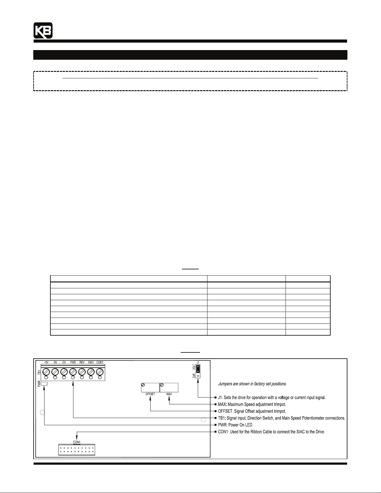
The main features of the SIAC include voltage or current signal inputs. Other features include a power on LED, a barrier terminal block to
facilitate wiring, multi-turn trimpots (MAX, OFFSET), and a selectable jumper for voltage or current signal input selection. An optional
accessory for use with the SIAC is an Auto/Manual Switch (Part No. 9481), which selects a signal input from either the SIAC or the Main
Speed Potentiometer of the drive.
2 FEATURES
▪ Isolated Switching: Provides isolation for PLC open collector or contact switching.
▪ Isolated +5V Power Supply: Used to power a transducer or to supply voltage for Main Speed Potentiometer operation.
▪ Power On LED: Provides indication that power is applied.
▪ Trimpot Adjustments (Multi-Turn): Maximum Speed (MAX) and Signal Offset (OFFSET).
▪ Signal Input Selection (Jumper J1): Selects voltage or current signal inputs.
▪ Optional Accessory: Auto/Manual Switch (Part No. 9481) selects a signal input from either the SIAC or the Main Speed Potentiometer.
▪ Easy Installation: A snap-in Mounting Base and Interconnecting Ribbon Cable are provided for easy installation into the drive.
General Performance Specifications
Parameter Specifications Factory Setting
Maximum Speed Trimpot (MAX) Input Voltage Range (Volts DC) 0 to 2.5 thru 0 to 25 0 to 5
Offset Trimpot (OFFSET) Range (% of MAX Trimpot Setting) 0 – ±50 0
Input Current Range (milliamps DC) 4 – 20 —
Forward and Reverse Input Switch Types Dry Contact or Open Collector —
+5V Power Supply Maximum Load Current Rating (milliamps DC) 25 —
Potentiometer Operation (kΩ) 5 —
Input/Output Linearity (%) 0.1 —
Thermal Drift (millivolts per °C) 0.4 —
Operating Temperature Range (°C / °F) 0 – 45 / 32 – 113 —
SIAC Signal Isolator Layout
Table 1
Figure 1
(A40149) – Rev. D00 – 4/21/2009 Page 1 of 6
Page 2
"The Right Control for Your Application" 12095 NW 39 Street, Coral Springs, FL 33065-2516
Telephone: 954-346-4900; Fax: 954-346-3377
KB Electronics, Inc. www.kbelectronics.com
SIAC 2G Signal Isolator (Part No. 9600) Installation Instructions
3 INSTALLATION INSTRUCTIONS
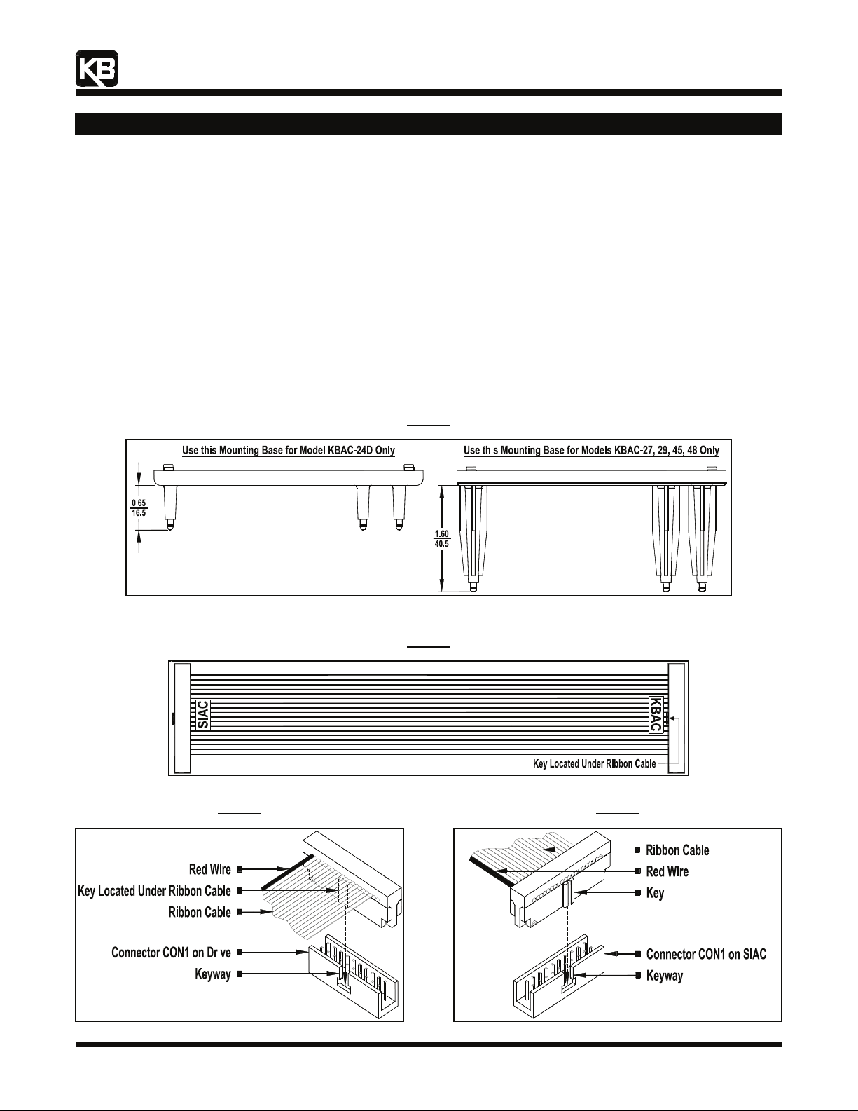
The SIAC Signal Isolator is designed to be installed into the drive with the snap-in mounting base. For Model KBAC-24D use the
mounting base with the shorter stand-offs (0.65" (16.5 mm)). For Models KBAC-27, 29, 45, 48 use the mounting base with the longer
stand-offs (1.60" (40.5 mm)). Figure 6, on page 3, shows the drive proor to installing the SIAC. See Figure 2, for the proper orientation of
the SIAC and the Ribbon Cable. See the Interconnecting Ribbon Cable, in Figure 3.
Note: Do not install the SIAC with Mounting Base into the drive until the Ribbon Cable is installed and routed under the Mounting Base.
3.1 Install the SIAC Signal Isolator onto the appropriate Mounting Base, as shown in Figure 2. Align the SIAC over the two PC board
supports (see Figure 7, on page 3) and gently press the SIAC onto the Mounting Base until the PC board is secured into place.
3.2 Install the end of the Ribbon Cable labelled "KBAC" onto CON1 of the drive. Orient the Ribbon Cable key as shown in Figure 4.
3.3 Install the end of the Ribbon Cable labelled "SIAC" onto CON1 on the SIAC. Orient the Ribbon Cable key, as shown in Figure 5.
3.4 Rotate the assembly (SIAC with Mounting Base and Ribbon Cable) horizontally 180°. The Ribbon Cable must be routed under the
Mounting Base. Align the four snap-ins, at the bottom ends of the Mounting Base support posts, with the 4 holes located on the
drive's PC board. Firmly push on the corners of the Mounting Base until all four snap-ins are secured into place. See Figures 6 and
7, on page 3.
Figure 2
Mounting Bases
Note: Dimensions are shown in Inches/mm.
Figure 4
Mating Ribbon Cable to CON1 on the Drive
Figure 3
Interconnecting Ribbon Cable
Figure 5
Mating Ribbon Cable to CON1 on the SIAC
(A40149) – Rev. D00 – 4/21/2009 Page 2 of 6
Page 3

"The Right Control for Your Application" 12095 NW 39 Street, Coral Springs, FL 33065-2516
Telephone: 954-346-4900; Fax: 954-346-3377
KB Electronics, Inc. www.kbelectronics.com
SIAC 2G Signal Isolator (Part No. 9600) Installation Instructions
Drive Prior to Installing the SIAC*
Figure 6
Figure 7
SIAC Installed Into the Drive*
*
*
(A40149) – Rev. D00 – 4/21/2009 Page 3 of 6
Page 4

"The Right Control for Your Application" 12095 NW 39 Street, Coral Springs, FL 33065-2516
Telephone: 954-346-4900; Fax: 954-346-3377
KB Electronics, Inc. www.kbelectronics.com
SIAC 2G Signal Isolator (Part No. 9600) Installation Instructions
4 WIRING INSTRUCTIONS
All connections are made on Terminal Block TB1 on the SIAC.
5 TRIMPOT ADJUSTMENTS
WARNING! Disconnect main power before making connections to the drive.
Table 2
SIAC Terminal Block TB1 Wiring Information
Maximum Wire Size (Cu) Recommended Tightening Torque
AWG mm2 in-lbs kg-cm
16 1.3 3.5 4
4.1 Voltage Following Connection: A 0 to 2.5 thru 0 to 25 Volt DC analog signal input can be used to control motor speed. Factory
setting is 0 to 5 Volts DC. The drive output will linearly follow the analog signal input. Wire the signal input positive lead (+) to
Terminal "SIG1" and the negative lead (-) to Terminal "COM1". For Forward Speed Operation, wire a jumper between Terminals
"0V" and "FWD". For Reverse Speed Operation wire a jumper between Terminals "0V" and "REV". Set Jumper J1 to the "VOLT"
position (factory setting). See Figure 9, on page 5.
Note: Do not use the MAX Trimpot on the drive when the SIAC is installed. Use the MAX Trimpot on the SIAC to scale the signal
input, as described in Section 5.1.
4.2 Current Following Connection: A 4 – 20 mA DC analog signal input can be used to control motor speed. The drive output will
linearly follow the analog signal input. Wire the signal input positive lead (+) to Terminal "SIG1" and the negative lead (-) to Terminal
"COM1". For Forward Speed Operation, wire a jumper between Terminals "0V" and "FWD". For Reverse Speed Operation wire
a jumper between Terminals "0V" and "REV". Set Jumper J1 to the "CUR" position. See Figure 10, on page 5.
Note: The MIN Trimpot on the drive is not functional when the SIAC is installed. Use the OFFSET Trimpot on the SIAC to offset
the signal input, as described in Section 5.2.
4.3 Unidirectional Main Speed Potentiometer with Forward-Stop-Reverse Switch Connections: A 5 kΩ potentiometer can be
used to control motor speed. Wire the potentiometer high side to Terminal "+5V", the wiper to Terminal "SIG1", and the low side to
Terminal "COM1". For selection of motor direction, wire a Forward-Stop-Reverse Switch to Terminals "0V", "FWD", and "REV".
See Figure 11, on page 5.
4.4 Form "C" Contact or Relay Forward-Stop-Reverse Connection: A form "C" contact or relay can be used to select motor
direction. Wire the circuit to Terminals "0V", "FWD", and "REV". See Figure 12, on page 5.
4.5 Open Collector Forward-Stop-Reverse Connection: An open collector circuit can be used to select motor direction. Wire the
circuit to Terminals "0V", "FWD", and "REV". See Figure 13, on page 5.
The SIAC contains trimpots which are factory set for most applications. The SIAC is factory set for Voltage Following Operation to run the
motor from zero speed to full speed with a 0 to 5 Volt DC analog signal input. For Current Following Operation, see Section 5.2. Some
applications may require readjustment of the trimpots in order to tailor the drive for a specific application.
5.1 Maximum Speed Trimpot (MAX): The MAX Trimpot is factory set to run the motor at full speed with a 5 Volt DC analog signal
input. For a higher analog signal input (25 Volt DC max.), rotate the MAX Trimpot counterclockwise. For a lower analog signal input
(2.5 Volt DC min.), rotate the MAX Trimpot clockwise. See Figure 8.
Note: The MAX Trimpot on the drive has been factory set to an Upper Frequency Limit of 60 Hz (50 Hz, for 50 Hz motors). If the
application requires a slightly higher maximum frequency (up to 66 Hz), rotate the MAX Trimpot on the drive to full clockwise
position.
5.2 Signal Offset (OFFSET): The OFFSET Trimpot is used to recalibrate the drive for Current Following Operation. The SIAC will run
the motor from zero speed to full speed with a 4 – 20 mA DC analog signal input. For a higher minimum speed setting, rotate the
OFFSET trimpot clockwise. For a lower minimum speed setting, rotate the OFFSET Trimpot counterclockwise. See Figure 8.
Note: The MIN Trimpot on the drive is not functional when the SIAC is installed.
Figure 8
Trimpot Adjustments
+
+
(A40149) – Rev. D00 – 4/21/2009 Page 4 of 6
Page 5

"The Right Control for Your Application" 12095 NW 39 Street, Coral Springs, FL 33065-2516
Telephone: 954-346-4900; Fax: 954-346-3377
KB Electronics, Inc. www.kbelectronics.com
SIAC 2G Signal Isolator (Part No. 9600) Installation Instructions
(Terminal Block TB1 is Isolated from the AC Line and Motor Wiring)
Figure 9
Voltage Following
Signal Input Connection
(J1 Set to "VOLT" Position)
(Shown in Forward Speed Operation)
SIAC CONNECTION DIAGRAMS
Figure 10
Current Following
Signal Input Connection
(J1 Set to "CUR" Position)
(Shown in Forward Speed Operation)
Figure 11
Unidirectional
Main Speed Potentiometer with
Forward-Stop-Reverse Switch Connections
(J1 Set to "VOLT" Position)
+
*Factory calibrated for 0 to 5 Volts DC signal input.
+
Figure 12
Form "C" Contact or Relay
Forward-Stop-Reverse Connection
Forward-Stop-Reverse Connection
Figure 13
Open Collector
6 SETTING SELECTABLE JUMPER J1 (Analog Signal Input Selection)
Jumper J1 must be set before the drive can be used. For the location of Jumper J1, see Figure 1, on page 1.
Jumper J1 is factory set to the "VOLT" position for Voltage Following Operation and Main Speed Potentiometer Operation, as shown in
Figures 9 and 11, above. For Current Following Operation, set Jumper J1 to the "CUR" position, as shown in Figure 10, above. See
Sections 4.1 – 4.3, on page 4.
(A40149) – Rev. D00 – 4/21/2009 Page 5 of 6
Page 6

"The Right Control for Your Application" 12095 NW 39 Street, Coral Springs, FL 33065-2516
Telephone: 954-346-4900; Fax: 954-346-3377
KB Electronics, Inc. www.kbelectronics.com
SIAC 2G Signal Isolator (Part No. 9600) Installation Instructions
LIMITED WARRANTY
For a period of 18 months from the date of original purchase, KB Electronics, Inc. will repair or replace without charge, devices which our
examination proves to be defective in material or workmanship. This warranty is valid if the unit has not been tampered with by unauthorized
persons, misused, abused, or improperly installed and has been used in accordance with the instructions and/or ratings supplied. The
foregoing is in lieu of any other warranty or guarantee, expressed or implied. KB Electronics, Inc. is not responsible for any expense,
including installation and removal, inconvenience, or consequential damage, including injury to any person, caused by items of our
manufacture or sale. Some states do not allow certain exclusions or limitations found in this warranty and therefore they may not apply to
you. In any event, the total liability of KB Electronics, Inc. under any circumstance, shall not exceed the full purchase price of this product.
(rev 2/2000)
COPYRIGHT © 2009 KB Electronics, Inc.
All rights reserved. In accordance with the United States Copyright Act of 1976, no part of this publication may be reproduced in any form or
by any means without permission in writing from KB Electronics, Inc. (8/2002)
KB Electronics, Inc.
12095 NW 39th Street, Coral Springs, FL 33065-2516 ● (954) 346-4900 ● FAX (954) 346-3377
Outside Florida Call Toll Free (800) 221-6570 ● info@kbelectronics.com
www.kbelectronics.com
(A40149) – Rev. D00 – 4/21/2009 Page 6 of 6
 Loading...