


Kawasaki Vulcan 1600 Nomad, VN1600 CLASSIC TOURER Assembly & Preparation Manual
VULCAN 1600 NOMAD
VN1600 CLASSIC TOURER
Motorcycle
Assembly & Preparation
Manual
Foreword
In order to ship Kawasaki vehicles as efficiently as possible, they are partially disassembled before crating. Since some of the most
commonly removed parts have a direct bearing on a vehicle’s reliability and safety, conscientious pre-sale assembly and preparation becomes extremely important. Good setup procedures can prevent needless warranty claims
and give customers a greater sense of confidence in Kawasaki and their Kawasaki Dealers.
This Assembly and Preparation Manual explains step by step procedures of the following
items for all Kawasaki motorcycles.
1. Uncrating
2. Assembly
3. Preparation
The selling dealer assumes sole responsibility for any unauthorized modifications prior to
sale. Refer to your Service Binder for any Service Bulletins specifying Factory Directed Modifications (Special Claims) which must be performed before the vehicle is ready for sale.
Whenever you see the following symbols
heed their instructions! Always follow safe
operating and maintenance practices.
WARNING
This warning symbol identifies special
instructions or procedures which, if not
correctly followed, could result in personal injury, or less of life.
CAUTION
This caution symbol identifies special
instructions or procedures which, if not
correctly followed, could result in damage to, or destruction of equipment.
NOTE
żThis note symbol indicates points of particular
interest for more efficient and convenient operation.
Kawasaki Heavy Industries, Ltd. accepts no
liability for any inaccuracies or omissions in this
publication, although every possible measure
has been taken to make it as complete and accurate as possible. All procedures and specifications subject to change without notice.
© 2004 Kawasaki Heavy Industries, Ltd. Nov. 2004 (K)

Table of Contents
crating ......................................................................................
Un
Opening Crate ............................................................................. 3
Parts Check ................................................................................. 4
sembly ......................................................................................
As
Handlebar.................................................................................... 8
Throttle Grip and Right Switch Housing ...................................... 8
ront Brake Master Cylinder .......................................................
F
Left Switch Housing..................................................................... 9
Clutch Master Cylinder ................................................................ 10
iring Clamps .............................................................................10
W
Front Fender................................................................................ 11
Front Wheel Installation............................................................... 12
Front Brake Hose Grommets ...................................................... 14
Front and Rear Shift Pedals ........................................................ 14
Front Footboard (Left) ................................................................. 15
Front Guards (Left and Right) ..................................................... 15
Helmet Locks............................................................................... 16
Rear Guards (Left and Right) ...................................................... 16
Backrest Pad ............................................................................... 17
Horn............................................................................................. 17
Choke Knob................................................................................. 18
Rear View Mirrors (Left and Right) .............................................. 18
Windshield................................................................................... 19
License Plate Bracket.................................................................. 21
Rear Reflectors and License Plate Holder .................................. 21
Left Saddlebag ............................................................................ 22
Brake Disc Cleaning .................................................................... 24
Preparation ................................................................................... 24
Battery Service ............................................................................ 24
Front Brake Fluid ......................................................................... 30
Rear Brake Fluid ......................................................................... 31
Clutch Fluid ................................................................................. 32
Rear Shock Absorber .................................................................. 34
Tire Air Pressures........................................................................ 34
Fuel ............................................................................................. 34
Coolant ........................................................................................ 34
Engine Oil (4-stroke) ................................................................... 35
Final Gear Case Oil..................................................................... 36
Throttle Grip and Cable ............................................................... 37
Headlight Aim .............................................................................. 38
Idle Speed Adjustment ................................................................ 38
Rear Brake Light Switch.............................................................. 38
Fastener Check ........................................................................... 40
Standard Torque Table ................................................................ 42
Test Ride the Motorcycle ............................................................. 42
A & P Check List ......................................................................... 42
3
8
9

Uncrating
Opening Crate
Clear a space about 6 m (20 ft.) square to
•
give yo
Place the crate upright on its base.
•
Remove the cardboard cover.
•
Remov
•
parts box.
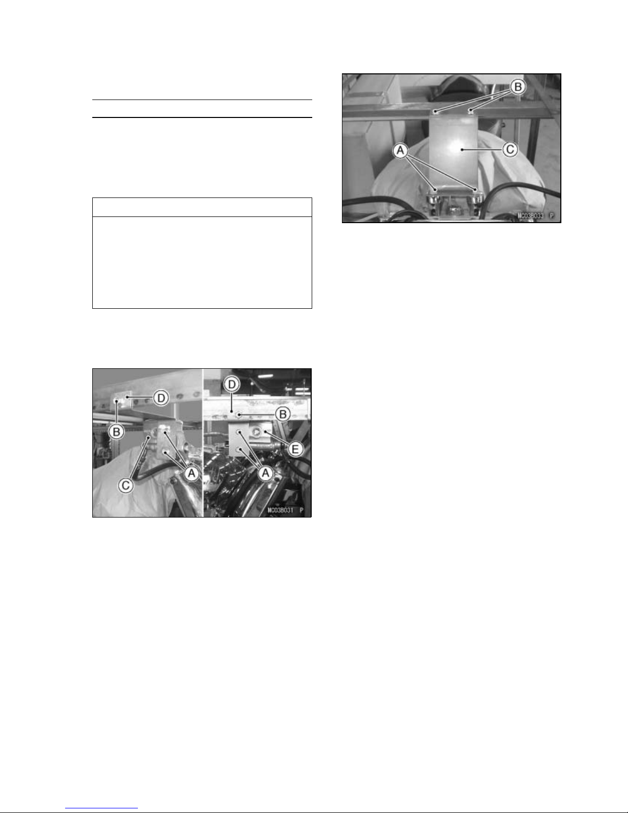
When you remove the crate bracket
from the motorcycle, be careful not to
drop any parts and bracket onto the
fuel tank and other components, and
not to scratch the fuel tank by the crate
bracket. This could damage the fuel
tank or components.
Unscrew the four bolts to remove the front
•
brake and clutch master cylinders.
Remove the two bracket bolts and the crate
•
bracket and discard them.
urself plenty of space to work.
e the handlebar, front wheel, and the
CAUTION
UNCRATI
A. Lower Bolts
B. Upper Bolts
C. Crate Bracket
Take out all the bolts and screws and remove
•
the top and sides of the crate.
NG 3
.Bolts
A
B. Bolt
C. Front Master Cylinder
D. Crate Bracket
E. Clutch Master Cylinder
Unscrew the two lower bolts, and then re-
•
move the two upper bolts and crate bracket.
Discard the bolts and bracket.
4 UNCRAT
ING
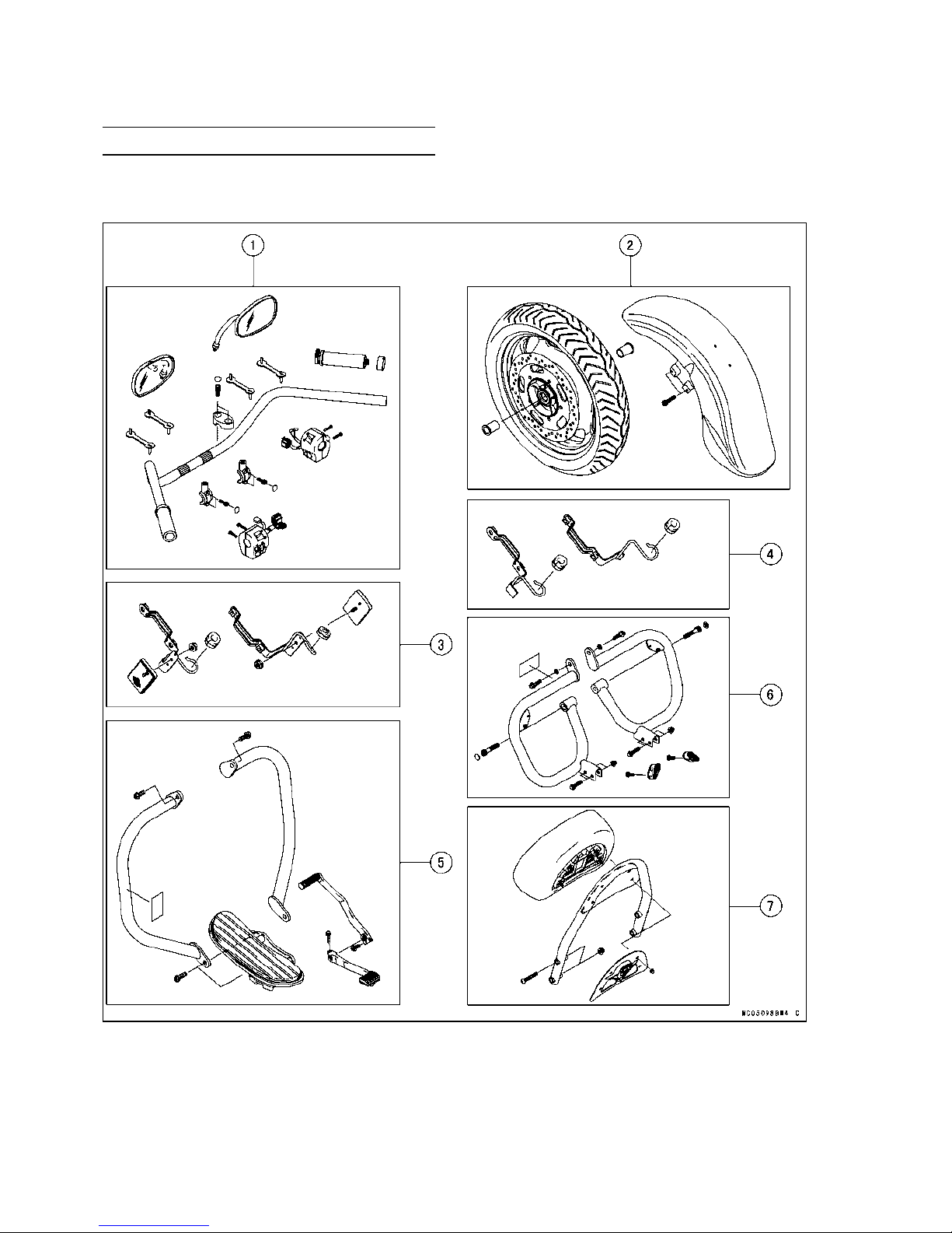
Parts Check
Open the parts box, and check the parts against the illustrations. There may be minor differences
•
between these illustrations and the actual vehicle parts. In the following charts under Remarks, D
= diameter in millimeters, L = length in millimeters, and T = Thickness in m illimeters.

UNCRATI
NG 5
No. Part Name
1
Handlebar with Grip
Handlebar Clamp
Clamp Bolt, Socket
Plastic Plug, Clamp Bolt
Throttle Grip
Clamp, Master Cylinder
Clamp Bolt, Master Cylinder, Socket
Plastic Plug, Clamp Bolt
Plastic Clamp, Wiring and Hose
Screw, Switch Housing, LH & RH
Rear View Mirror, LH & RH
Qty
1
2
4 D = 10, L = 23
4 Large
1
2
4 D=6,L=20
4
Small
4 L = 88.5
4 D=5,L=25
2
2 Front Wheel 1
Axle Collar, LH & RH
2 L = 46.5
Front Fender with Brace 1
Socket Bolt, Front Fender
3
For US and CN Models
Brake Hose Clamp, LH & RH
Grommet, Brake Hose
Front Reflector, LH & RH
Flanged Nut, Reflector
4
For other than US and CN Models
Brake Hose Clamp, LH & RH
Grommet, Brake Hose
5
Front Left Footboard Assembly
4 D=8,L=35
2
2
2
2 D=5
2
2
1
Flanged Bolt, Front Footboard, LH 2 D = 10, L = 30
Front Guard, LH & RH
Flanged Bolt, Front Guard
Warning Label, Front Left Guard
Front Shift Pedal
Rear Shift Pedal
Flanged Bolt, Front and Rear Shift Pedals
6
Rear Guard, LH & RH
Flanged Bolt with Washer, Rear Guard, Upper
Socket Bolt, Rear Guard, Lower
Plastic Plug, Socket Bolt, Rear Guard
Flanged Bolt, Rear Guard
Cap Nut, Rear Guard
Helmet Lock 2
Screw with Non-permanent locking agent, Helmet Lock
Warning Label, Rear Left Guard
2
2 D = 10, L = 25
1
US and CN Models Only
1
1
2 D=8,L=25
2
2 D=8,L=30
2 D = 10, L = 50
2 Large
4 D=8,L=35
4 D=8
Located in the left side cover.
2 D=5,L=12
1
US and CN Models Only
7 Backrest Pad 1
Backrest Frame 1
Cover with Mark, Backrest
Cap Nut, Cover
1
4 D=6
Bolt, Backrest Frame 4 D=8,L=50
Nut, Backrest Frame 4 D=8
Remarks
6 UNCRAT
ING
* : European Models Only

UNCRATI
NG 7
No. Part Name
Qty
Remarks
8 Horn with Bracket 1
Flanged Bolt, Horn 1
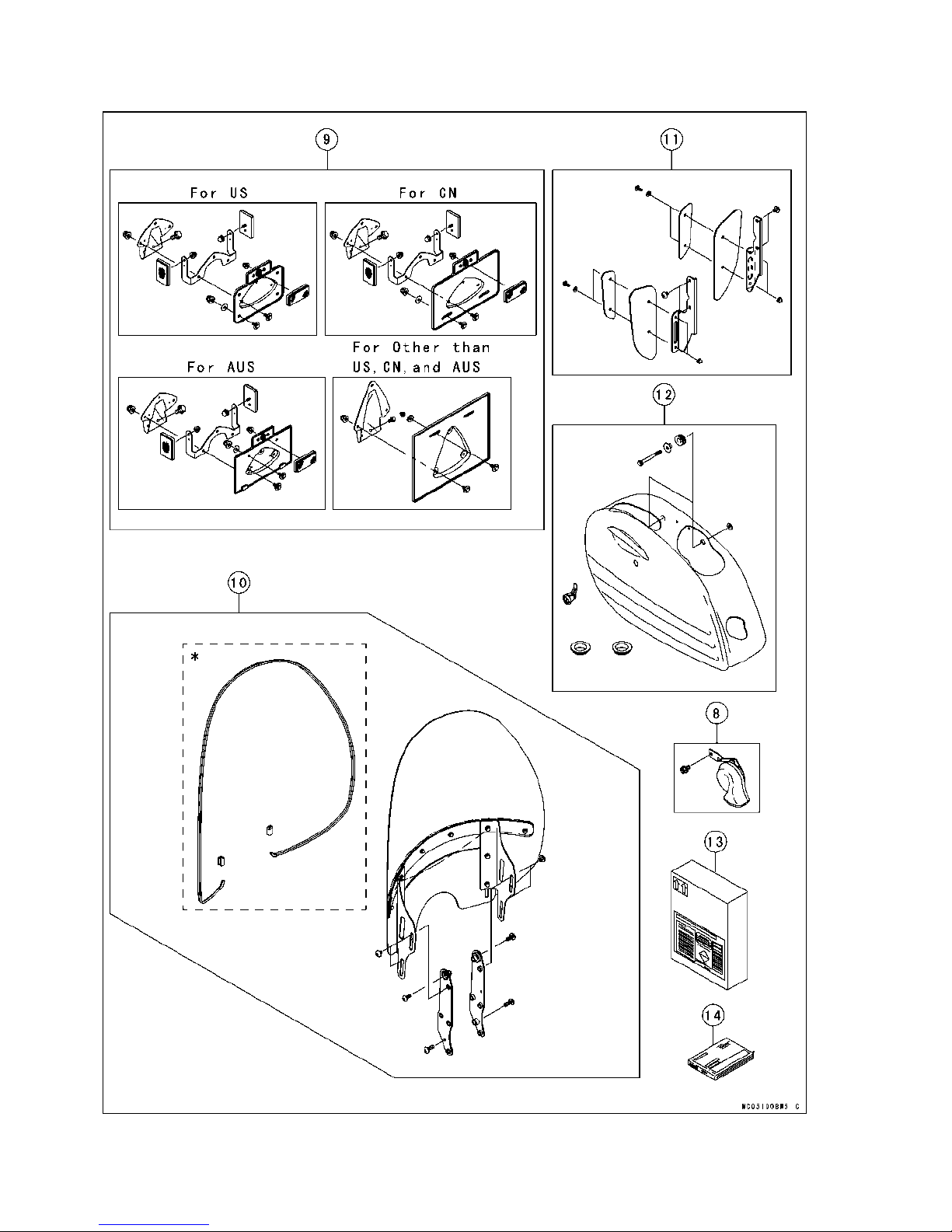
9 Licen
se Plate Bracket
1
Bolt, Bracket, License Plate 2 D=6,L=12
Bracket, Reflector
ector
Refl
1
(US)(CN)(AUS) only
(US)
(CN) only
3
Reflector 1 (AUS) only
Cap Nut, Reflector 3 D = 5, (US)(CN) only
Cap Nut, Reflector 1 D = 5, (AUS) only
Cap Nut, Black, License Plate
Cap Nut, Black, License Plate
Flat Washer, Black, Holder, License Plate 4
4
D = 6, (US) only
2
D = 6, (CN)(AUS)(EUR) only
6.5 × 20 × 1.6, (US) only
D=
Flat Washer, Black, Holder, License Plate 2 D = 6.5 × 20 × 1.6, (CN) (AUS)(EUR) only
Holder, License Plate 1
olt with Flat Washer
B
Bolt with Flat Washer 5
Cap Nut, Holder, License Plate
7 D = 6, L = 14 (US only)
D = 6, L = 14, (CN)(AUS)(EUR) only
3 D=6
10 Windshield Assembly with 1
Center Plate, Outer & Inner (2)
Damper, Center Plate, Outer & Inner (2)
Socket Bolt with Washer, Center Plate (4)
Cap Nut (10)
Vulcan Mark
D=6,L=20
D=6
(1) (US)(CN)(AUS) only
VN1600 Mark (1) (EUR) only
Outer Plate, LH & RH (2)
Inner Plate, LH & RH (2)
Outer Damper, Outer Plate, LH & RH (2)
Inner Damper, Inner Plate, LH & RH (2)
Socket Bolt with Washer, Outer & Inner Plate (6)
D=6,L=25
Sub-windshield (1)
Stay, Windshield, LH & RH (2)
Trim, Windshield 1 L = 1 900, (EUR) only
Clamp, Trim
Socket Bolt, Stay
Bracket, Windshield, LH & RH
2
(EUR) only
4 D=8,L=10
2
Socket Bolt, Bracket, Upper 2 D=8,L=20
Socket Bolt, Bracket, Lower 2 D=8,L=25
11 Outer Plate, Deflector, LH & RH 2
Deflector, LH & RH
Stay, LH & RH
Socket Bolt with Washer
2
2
4 D=6,L=16
Cap Nut 4 D=6
Socket Bolt, Stay 4 D=6,L=16
12 Saddlebag, LH 1
Lock, Saddlebag
1
Located in the left side cover.
Damper, Bottom 2 Large
Damper, Upper 2 D=12
Flanged Collar 2 D = 12, L = 13.1
Flanged Bolt, Saddlebag 2 D=8,L=75
Flat Washer, Saddlebag, Black 4 D = 8.5 × 20, T = 1.6
13
Battery Electrolyte, FTZ16-BS
14
Owner’s Manual
1
1
AUS:
Australian Model EUR: European Model
CN: CN Model US: United States Model
8 ASSEMB
LY
Assembly
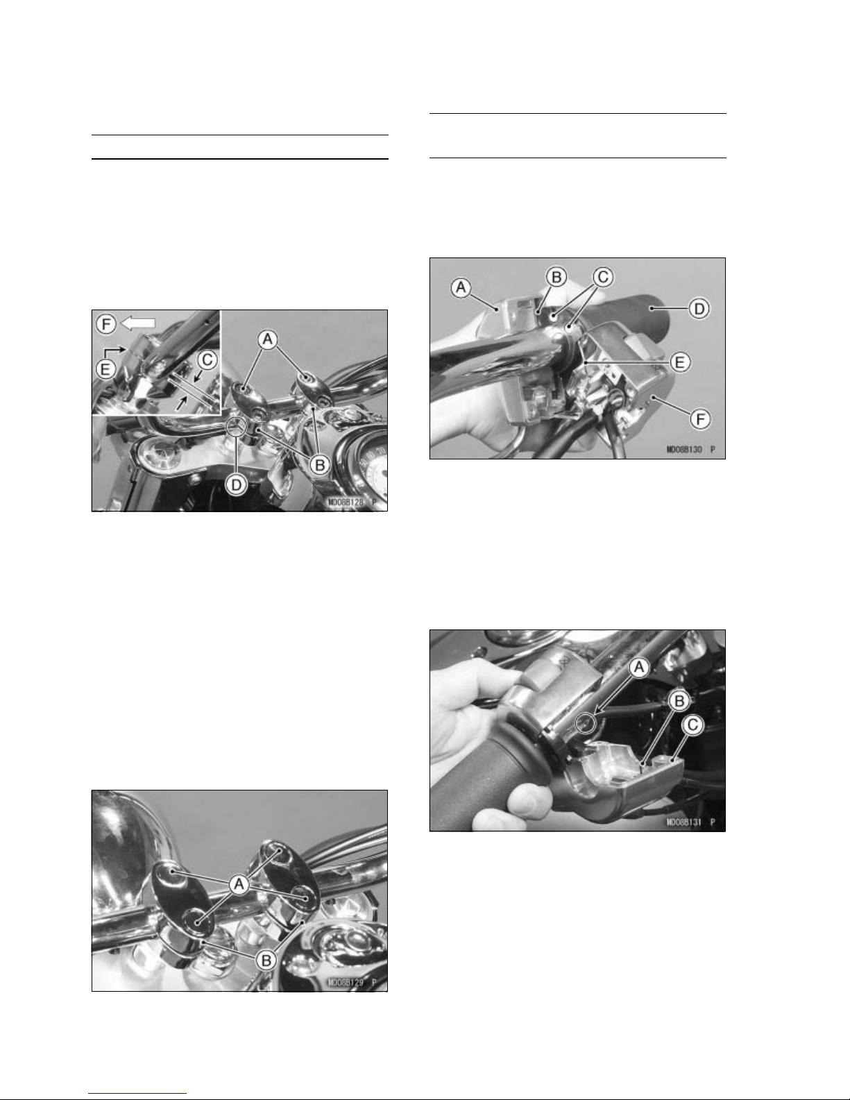
Handlebar
NOTE
żPosition the handlebar clamp on the handle-
bar with the slanted side facing rearward.
e handlebar to match its punched mark
Set th
•
to the rear portion of the lower clamp mating
face and install the upper clamps and bolts (D
=10,L
A. Front Bolts
B. Slanted Side
C.
D. Punched Mark
E. No Gap
. Forward
F
Handlebar Clamp Bolt Tightening
Tighten the front clamp bolts first, and then
•
the rear clamp bolts to the specified torque.
There will be a gap at the rear part of the
clamp after tightening.
Torque:
= 23).
Gap
34 N·m (3.5 kgf·m, 25 ft·lb)
Throttle Grip and Right Switch
Housing
Alignm
Apply a light coat of grease on the exposed
•
portion of the throttle inner cables.
Fit bot
•
socket in the throttle grip.
A. F
B. Throttle Cable (Accelerator)
C. Cable Tips: Apply Grease.
D. Throttle Grip
E. Throttle Cable (Decelerator)
F. Rear Half (Right Switch Housing)
Fit the two halves of the right switch housing
•
so that the pin on the front half fits into the
hole in the handlebar.
ent Pin Type
h throttle cable tips into the nearest
ront Half (Right Switch Housing)
Push the large plastic plugs (4) into the han-
•
dlebar clamp bolts.
A. Plastic Plugs
B. Handlebar Clamps
A. Hole
B. Pin
C. Front Half
Insert the two screws (D = 5, L = 25) and
•
tighten them.
Tighten the holder screw.
•
Check that the throttle grip moves smoothly
•
from full open to close, and the throttle closes
quickly and completely.
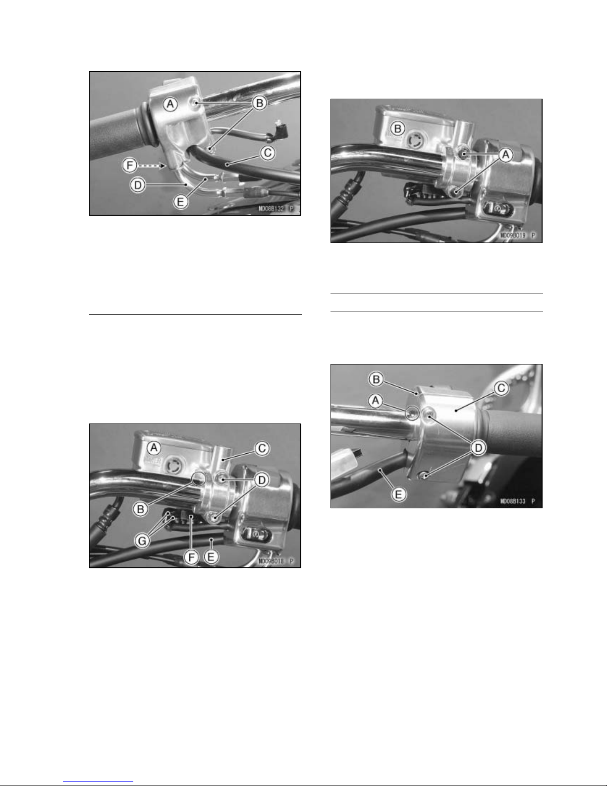
A. Right Switch Housing
crews (L = 25)
B. S
C. Harness
D. Throttle Cable (Accelerator)
E. Throttle Cable (Decelerator)
F. Holder Screw
Front Brake Master Cylinder
Connect the right switch housing lead con-
•
nectors to the front brake light switch terminals on the front brake master cylinder.
Apply silicone grease or PBC grease to the
•
master cylinder clamp bolts.
Install the front master cylinder with its clamp
•
and the two socket bolts (D = 6, L = 20).
ASSEMBL
Push the small plastic plugs (2) into the mas-
•
ter cylinder clamp bolts.
A. Plastic Plugs
aster Cylinder
B. M
Left Switch Housing
Fit the two halves of the left switch housing
•
together so that the vertical parting line of the
front and rear halves align with the punched
mark on the handlebar.
Y9
A. Front Master Cylinder
B. Punched Mark
C. Clamp
D. Socket Bolts
E. Harness
F. Front Brake Light Switch
G. Connectors and Dust Covers
Position the master cylinder so that the gap
•
between the front and rear master cylinder
clamps aligns with the punched mark on the
handlebar.
Tighten the upper clamp bolt first and then the
•
lower bolt to the specified torque.
Torque:
8.8 N·m (0.90 kgf·m, 78 in·lb)
A. Punched Mark
B. Rear Half (Left Switch Housing)
C. Front Half
D. Screws (L = 25)
E. Harness
Insert the two screws (D = 5, L = 25) and
•
tighten them securely.
10 ASSEM
BLY
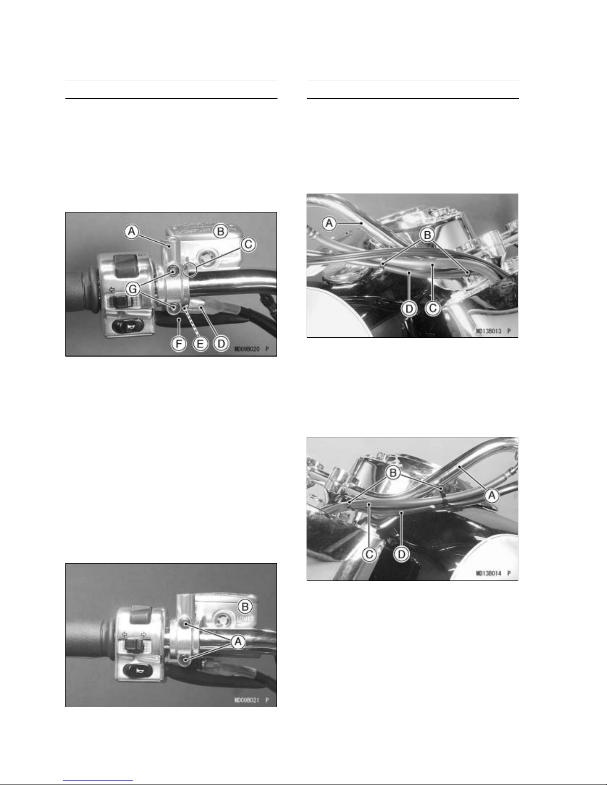
Clutch Master Cylinder
Apply silicone grease or PBC grease to the
•
master cylinder clamp bolts.
Install the clutch master cylinder with its
•
clamp and the two socket bolts (D = 6, L =
20).
Position the master cylinder so that the gap
•
between the front and rear master cylinder
clamps aligns with the punched mark on the
handlebar.
A. Clamp
B. Clutch Master Cylinder
C. Punched Mark
D. Connector and Dust Cover
E. Starter Lock-out Switch
F. Harness
G. Socket Bolts
Wiring Clamps
Fasten the front brake hose and the right
•
switch housing harness to the right side of
the handlebar with two plastic clamps.
NOTE
żThe plastic clamp at the inside fastens the
switch harness only.
right
A. Handlebar (Right Side)
lastic Clamps
B. P
C. Front Brake Hose
D. Right Switch Harness
Fasten the clutch hose and the left switch
•
housing harness to the left side of the handlebar with two plastic clamps.
Connect the connector of the left switch hous-
•
ing to the starter lock-out switch on the master
cylinder.
Tighten the upper clamp bolt first and then the
•
lower bolt to the specified torque.
Torque: 11 N·m (1.1 kgf·m, 97 in·lb)
Push the small plastic plugs (2) into the clutch
•
master cylinder clamp bolts.
A. Plastic Plugs
B. Clutch Master Cylinder
A. Handlebar (Left Side)
B. Plastic Clamps
C. Clutch Hose
D. Left Switch Harness
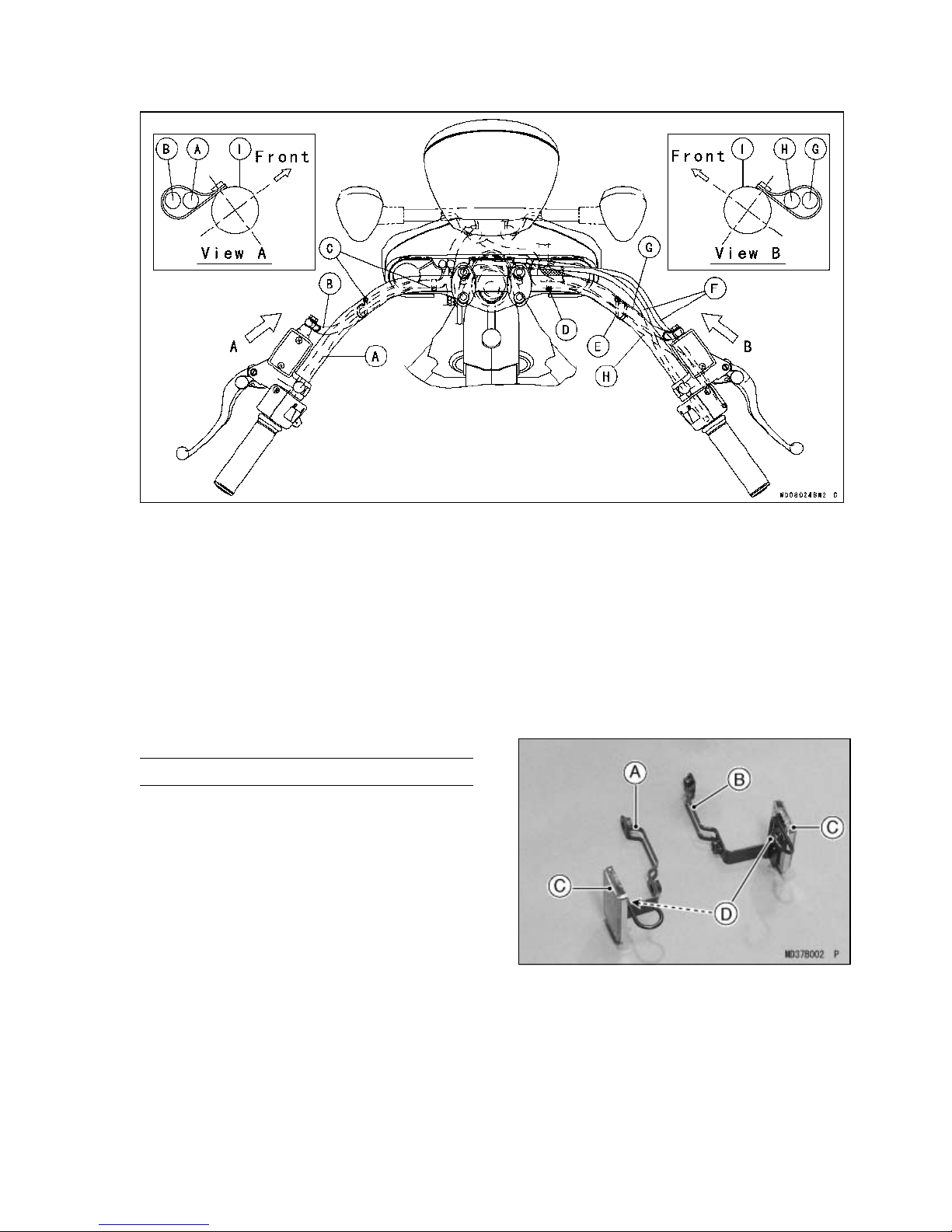
ASSEMBL
Y11
A. Left Switch Lead
B. Clutch Hose
C. Fasten the left switch lead and the clutch hose with two plastic clamps.
D. Fasten the right switch lead with the plastic clamp.
E. Fasten the right switch lead and the brake hose with the plastic clamp.
Throttle Cables
F.
G. Brake Hose
H. Right Switch Lead
Handlebar
I.
Front Fender
Front Reflectors (for US and CN Models
only)
Assemble the front left and right reflectors and
•
the brake hose clamps with the nut (D = 5) on
each.
A. Front Brake Hose Clamp (Left)
B. Front Brake Hose Clamp (Right)
C. Front Reflectors
D. Nuts
12 ASSEM
BLY
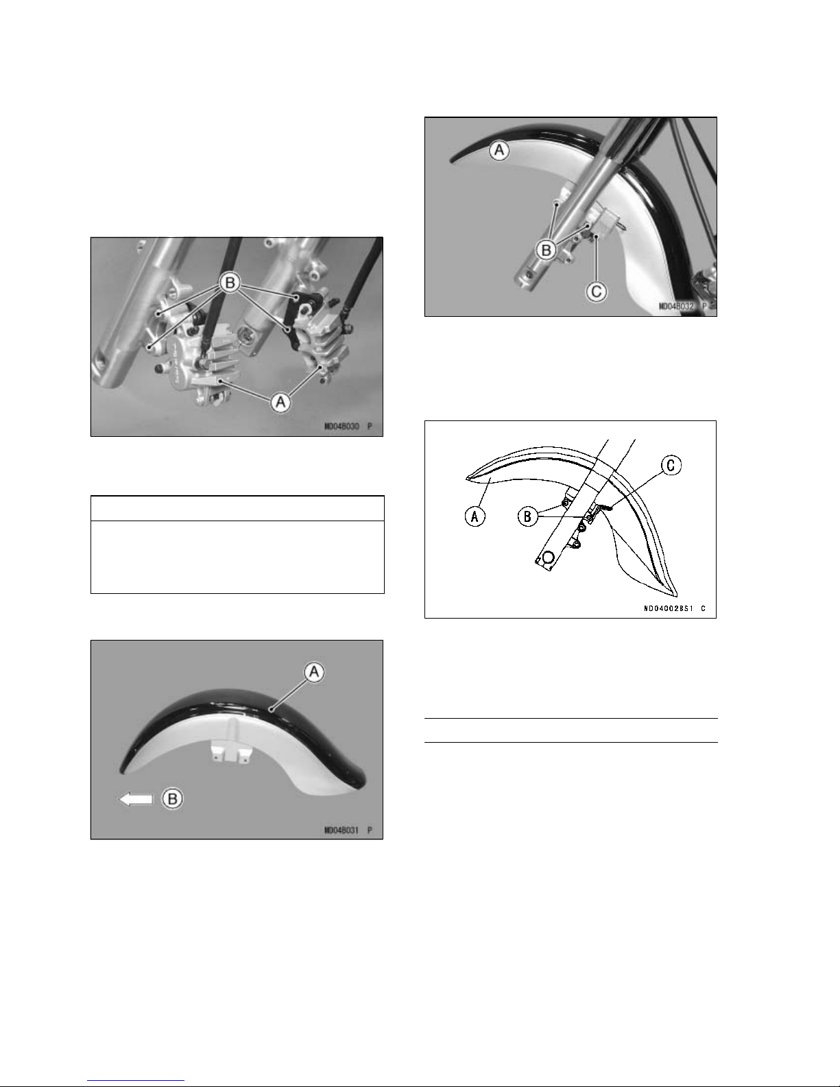
Front Fender Installation
Lift the motorcycle off the crate base and sup-
•
port the motorcycle with a suitable stand or
jack.
Loosen the axle clamp bolts on the right fork
•
leg and remove the front axle.
Loosen the two flanged bolts (D = 10, L = 47)
•
to remove each front brake caliper.
A. Front Brake Calipers
B. Flanged Bolts (D = 10, L = 47)
US and CN Models
A. Front Fender
B. Bolts (D = 8, L = 35)
C. Brake Hose Clamp (Left)
Other than US and CN Models
CAUTION
Do not leave the calipers hanging by
the brake hoses. After removing the
calipers, secure them to the frame using
a suitable band.
Install the front fender with its more rounded
•
end facing forward.
A. Front Fender
B. Forward
Install the front fender on the fork legs, and in-
•
stall the front left and right brake hose clamps
on the inside of the fender with the four bolts
(D = 8, L = 35) and tighten them.
A. Front Fender
B. Bolts (D = 8, L = 35)
C. Brake Hose Clamp (Left)
Front Wheel Installation
Check the wheel rotation mark on the front
•
tire.
NOTE
żThe direction of the wheel rotation is shown
by an arrow on the front tire. Install the wheel
so that the rotation mark coincides with wheel
rotational direction.
 Loading...