


1400GTR CONCOURS 14 ABS CONCOURS 14
Motorcycle
Service Manual

This product contains the encryption algorithm "MISTY" developed by MITSUBISHI ELECTRIC CORPORATION.

Quick Reference Guide
This quick reference guide will assist you in locating a desired topic or procedure.
•Bend the pages back to match the black tab of the desired chapter number with the black tab on the edge at each table of contents page.
•Refer to the sectional table of contents for the exact pages to locate the specific topic required.
General Information |
1 |
j |
|
|
|
Periodic Maintenance |
2 |
j |
|
|
|
Fuel System (DFI) |
3 |
j |
|
|
|
Cooling System |
4 |
j |
|
|
|
Engine Top End |
5 |
j |
|
|
|
Clutch |
6 |
j |
|
|
|
Engine Lubrication System |
7 |
j |
|
|
|
Engine Removal/Installation |
8 |
j |
|
|
|
Crankshaft/Transmission |
9 |
j |
|
|
|
Wheels/Tires |
10 |
j |
|
|
|
Final Drive |
11 |
j |
|
|
|
Brakes |
12 |
j |
|
|
|
Suspension |
13 |
j |
|
|
|
Steering |
14 |
j |
|
|
|
Frame |
15 |
j |
|
|
|
Electrical System |
16 |
j |
|
|
|
Appendix |
17 |
j |

1400GTR CONCOURS 14 ABS CONCOURS 14
Motorcycle
Service Manual
All rights reserved. No parts of this publication may be reproduced, stored in a retrieval system, or transmitted in any form or by any means, electronic mechanical photocopying, recording or otherwise, without the prior written permission of Quality Assurance Division/Consumer Products & Machinery Company/Kawasaki Heavy Industries, Ltd., Japan.
No liability can be accepted for any inaccuracies or omissions in this publication, although every possible care has been taken to make it as complete and accurate as possible.
The right is reserved to make changes at any time without prior notice and without incurring an obligation to make such changes to products manufactured previously. See your Motorcycle dealer for the latest information on product improvements incorporated after this publication.
All information contained in this publication is based on the latest product information available at the time of publication. Illustrations and photographs in this publication are intended for reference use only and may not depict actual model component parts.
© 2007 Kawasaki Heavy Industries, Ltd. |
First Edition (1): June 29, 2007 (M) |
LIST OF ABBREVIATIONS
A |
ampere(s) |
lb |
pound(s) |
ABDC |
after bottom dead center |
m |
meter(s) |
AC |
alternating current |
min |
minute(s) |
ATDC |
after top dead center |
N |
newton(s) |
BBDC |
before bottom dead center |
Pa |
pascal(s) |
BDC |
bottom dead center |
PS |
horsepower |
BTDC |
before top dead center |
psi |
pound(s) per square inch |
°C |
degree(s) Celsius |
r |
revolution |
DC |
direct current |
rpm |
revolution(s) per minute |
F |
farad(s) |
TDC |
top dead center |
°F |
degree(s) Fahrenheit |
TIR |
total indicator reading |
ft |
foot, feet |
V |
volt(s) |
g |
gram(s) |
W |
watt(s) |
h |
hour(s) |
Ω |
ohm(s) |
L |
liter(s) |
|
|
COUNTRY AND AREA CODES
AT |
Austria |
FR |
France |
AU |
Australia |
GB |
United Kingdom |
CA |
Canada |
MY |
Malaysia |
CAL |
California |
US |
United States |
CH |
Switzerland |
WVTA |
Whole Vehicle Type Approval |
DE |
Germany |
|
|

EMISSION CONTROL INFORMATION
To protect the environment in which we all live, Kawasaki has incorporated crankcase emission (1) and exhaust emission (2) control systems in compliance with applicable regulations of the United States Environmental Protection Agency and California Air Resources Board. Additionally, Kawasaki has incorporated an evaporative emission control system (3) in compliance with applicable regulations of the California Air Resources Board on vehicles sold in California only.
1. Crankcase Emission Control System
This system eliminates the release of crankcase vapors into the atmosphere. Instead, the vapors are routed through an oil separator to the inlet side of the engine. While the engine is operating, the vapors are drawn into combustion chamber, where they are burned along with the fuel and air supplied by the fuel injection system.
2. Exhaust Emission Control System
This system reduces the amount of pollutants discharged into the atmosphere by the exhaust of this motorcycle. The fuel, ignition, and exhaust systems of this motorcycle have been carefully designed and constructed to ensure an efficient engine with low exhaust pollutant levels.
The exhaust system of this model motorcycle manufactured primarily for sale in California includes a catalytic converter system.
3. Evaporative Emission Control System
Vapors caused by fuel evaporation in the fuel system are not vented into the atmosphere. Instead, fuel vapors are routed into the running engine to be burned, or stored in a canister when the engine is stopped. Liquid fuel is caught by a vapor separator and returned to the fuel tank.
The Clean Air Act, which is the Federal law covering motor vehicle pollution, contains what is commonly referred to as the Act’s “tampering provisions”.
“Sec. 203(a) The following acts and the causing thereof are prohibited...
(3)(A) for any person to remove or render inoperative any device or element of design installed on or in a motor vehicle or motor vehicle engine in compliance with regulations under this title prior to its sale and delivery to the ultimate purchaser, or for any manufacturer or dealer knowingly to remove or render inoperative any such device or element of design after such sale and delivery to the ultimate purchaser.
(3)(B) for any person engaged in the business of repairing, servicing, selling, leasing, or trading motor vehicles or motor vehicle engines, or who operates a fleet of motor vehicles knowingly to remove or render inoperative any device or element of design installed on or in a motor vehicle or motor vehicle engine in compliance with regulations under this title following its sale and delivery to the ultimate purchaser...”
NOTE
○The phrase “remove or render inoperative any device or element of design” has been generally interpreted as follows.
1.Tampering does not include the temporary removal or rendering inoperative of devices or elements of design in order to perform maintenance.
2.Tampering could include.
a.Maladjustment of vehicle components such that the emission standards are exceeded.
b.Use of replacement parts or accessories which adversely affect the performance or durability of the motorcycle.
c.Addition of components or accessories that result in the vehicle exceeding the standards.
d.Permanently removing, disconnecting, or rendering inoperative any component or element of design of the emission control systems.
WE RECOMMEND THAT ALL DEALERS OBSERVE THESE PROVISIONS OF FEDERAL LAW, THE VIOLATION OF WHICH IS PUNISHABLE BY CIVIL PENALTIES NOT EXCEEDING $10 000 PER VIOLATION.

TAMPERING WITH NOISE CONTROL SYSTEM PROHIBITED
Federal law prohibits the following acts or the causing thereof. (1) The removal or rendering inoperative by any person other than for purposes of maintenance, repair, or replacement, of any device or element of design incorporated into any new vehicle for the purpose of noise control prior to its sale or delivery to the ultimate purchaser or while it is in use, or (2) the use of the vehicle after such device or element of design has been removed or rendered inoperative by any person.
Among those acts presumed to constitute tampering are the acts listed below.
•Replacement of the original exhaust system or muffler with a component not in compliance with Federal regulations.
•Removal of the muffler(s) or any internal portion of the muffler(s).
•Removal of the air box or air box cover.
•Modifications to the muffler(s) or air inlet system by cutting, drilling, or other means if such modifications result in increased noise levels.
Foreword
This manual is designed primarily for use by trained mechanics in a properly equipped shop. However, it contains enough detail and basic information to make it useful to the owner who desires to perform his own basic maintenance and repair work. A basic knowledge of mechanics, the proper use of tools, and workshop procedures must be understood in order to carry out maintenance and repair satisfactorily. Whenever the owner has insufficient experience or doubts his ability to do the work, all adjustments, maintenance, and repair should be carried out only by qualified mechanics.
In order to perform the work efficiently and to avoid costly mistakes, read the text, thoroughly familiarize yourself with the procedures before starting work, and then do the work carefully in a clean area. Whenever special tools or equipment are specified, do not use makeshift tools or equipment. Precision measurements can only be made if the proper instruments are used, and the use of substitute tools may adversely affect safe operation.
For the duration of the warranty period, we recommend that all repairs and scheduled maintenance be performed in accordance with this service manual. Any owner maintenance or repair procedure not performed in accordance with this manual may void the warranty.
To get the longest life out of your vehicle.
•Follow the Periodic Maintenance Chart in the Service Manual.
•Be alert for problems and non-scheduled maintenance.
•Use proper tools and genuine Kawasaki Motorcycle parts. Special tools, gauges, and testers that are necessary when servicing Kawasaki motorcycles are introduced by the Service Manual. Genuine parts provided as spare parts are listed in the Parts Catalog.
•Follow the procedures in this manual carefully. Don’t take shortcuts.
•Remember to keep complete records of maintenance and repair with dates and any new parts installed.
How to Use This Manual
In this manual, the product is divided into its major systems and these systems make up the manual’s chapters. The Quick Reference
Guide shows you all of the product’s system and assists in locating their chapters. Each chapter in turn has its own comprehensive Table of Contents.
For example, if you want ignition coil information, use the Quick Reference Guide to locate the Electrical System chapter. Then, use the Table of Contents on the first page of the chapter to find the Ignition Coil section.
Whenever you see these WARNING and CAUTION symbols, heed their instructions! Always follow safe operating and maintenance practices.

 WARNING
This warning symbol identifies special instructions or procedures which, if not correctly followed, could result in personal injury, or loss of life.
CAUTION
This caution symbol identifies special instructions or procedures which, if not strictly observed, could result in damage to or destruction of equipment.
This manual contains four more symbols (in addition to WARNING and CAUTION) which will help you distinguish different types of information.
NOTE
○This note symbol indicates points of particular interest for more efficient and convenient operation.
•Indicatesdone. a procedural step or work to be ○Indicates a procedural sub-step or how to do the work of the procedural step it follows. It
also precedes the text of a NOTE.
 Indicates a conditional step or what action to take based on the results of the test or inspection in the procedural step or sub-step it follows.
In most chapters an exploded view illustration of the system components follows the Table of Contents. In these illustrations you will find the instructions indicating which parts require specified tightening torque, oil, grease or a locking agent during assembly.
GENERAL INFORMATION 1-1
General Information |
|
|
|
Table of Contents |
|
|
|
|
1 |
|
|
Before Servicing |
1-2 |
|
|
|
|
||
Model Identification................................................................................................................. |
1-7 |
|
|
General Specifications............................................................................................................ |
1-10 |
|
|
Technical Information-Variable Valve Timing .......................................................................... |
1-13 |
|
|
Technical Information-Electrical Windshield ........................................................................... |
1-17 |
|
|
Technical Information-KIPASS (Kawasaki’s Intelligent Proximity Activation Start System).... |
1-18 |
|
|
Technical Information-Tetra Lever Shaft Drive System........................................................... |
1-30 |
|
|
Unit Conversion Table ............................................................................................................ |
1-32 |
|
|
1-2 GENERAL INFORMATION
Before Servicing
Before starting to perform an inspection service or carry out a disassembly and reassembly operation on a motorcycle, read the precautions given below. To facilitate actual operations, notes, illustrations, photographs, cautions, and detailed descriptions have been included in each chapter wherever necessary. This section explains the items that require particular attention during the removal and reinstallation or disassembly and reassembly of general parts.
Especially note the following.
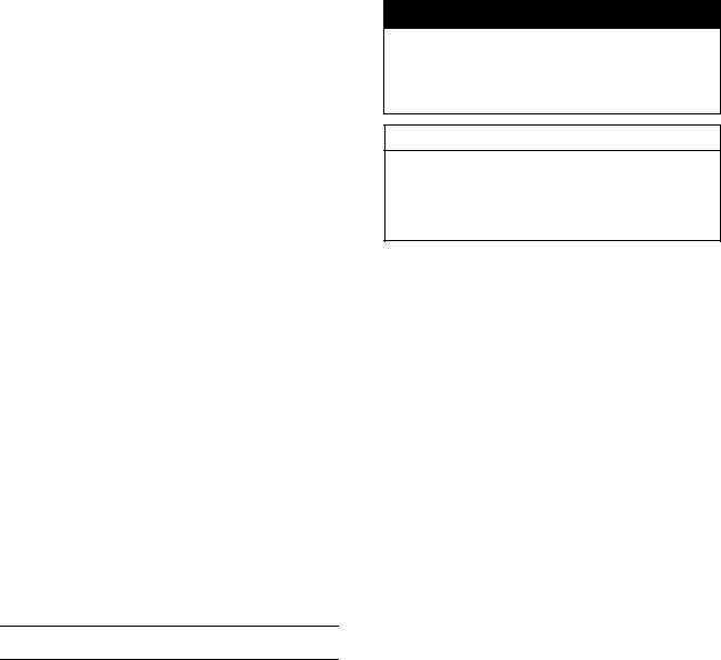
Battery Ground
Before completing any service on the motorcycle, disconnect the battery cables from the battery to prevent the engine from accidentally turning over. Disconnect the ground cable (–) first and then the positive (+). When completed with the service, first connect the positive (+) cable to the positive (+) terminal of the battery then the negative (–) cable to the negative terminal.
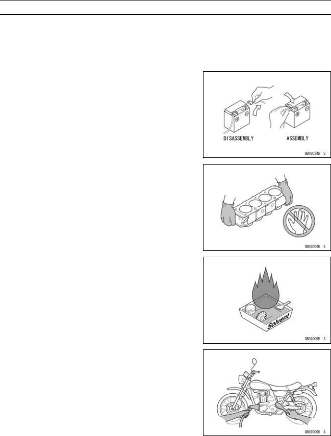
Edges of Parts
Lift large or heavy parts wearing gloves to prevent injury from possible sharp edges on the parts.
Solvent
Use a high-flush point solvent when cleaning parts. High -flush point solvent should be used according to directions of the solvent manufacturer.
Cleaning vehicle before disassembly
Clean the vehicle thoroughly before disassembly. Dirt or other foreign materials entering into sealed areas during vehicle disassembly can cause excessive wear and decrease performance of the vehicle.
GENERAL INFORMATION 1-3
Before Servicing
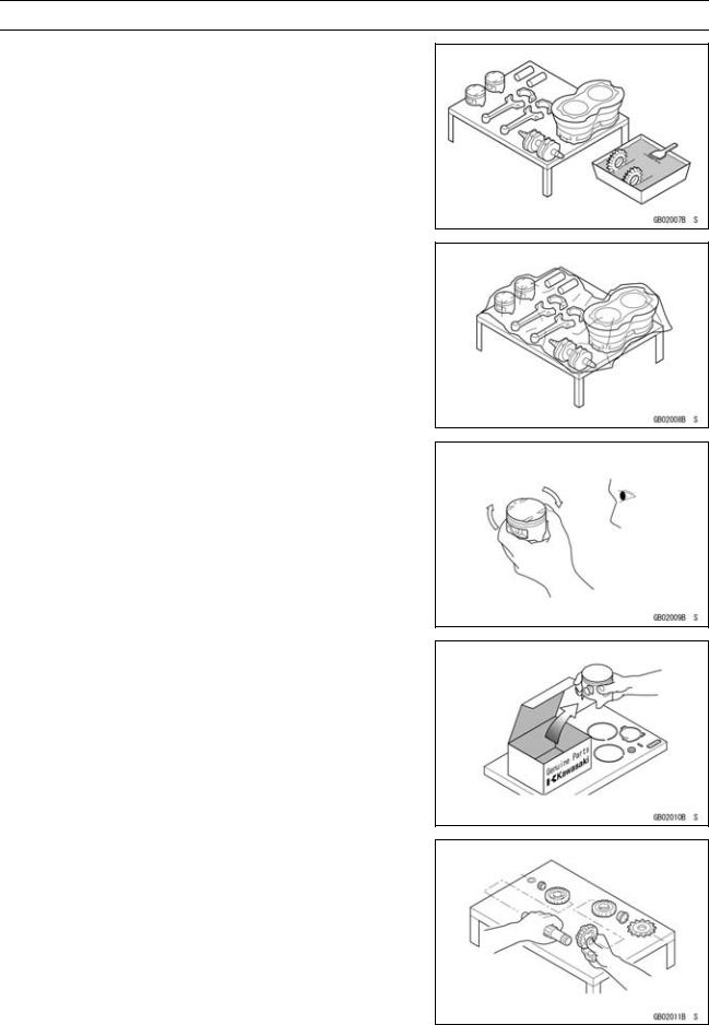
Arrangement and Cleaning of Removed Parts
Disassembled parts are easy to confuse. Arrange the parts according to the order the parts were disassembled and clean the parts in order prior to assembly.
Storage of Removed Parts
After all the parts including subassembly parts have been cleaned, store the parts in a clean area. Put a clean cloth or plastic sheet over the parts to protect from any foreign materials that may collect before re-assembly.
Inspection
Reuse of worn or damaged parts may lead to serious accident. Visually inspect removed parts for corrosion, discoloration, or other damage. Refer to the appropriate sections of this manual for service limits on individual parts. Replace the parts if any damage has been found or if the part is beyond its service limit.
Replacement Parts
Replacement Parts must be KAWASAKI genuine or recommended by KAWASAKI. Gaskets, O-rings, oil seals, grease seals, circlips or cotter pins must be replaced with new ones whenever disassembled.
Assembly Order
In most cases assembly order is the reverse of disassembly, however, if assembly order is provided in this Service Manual, follow the procedures given.
1-4 GENERAL INFORMATION
Before Servicing
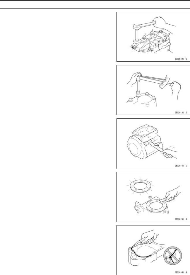
Tightening Sequence
Generally, when installing a part with several bolts, nuts, or screws, start them all in their holes and tighten them to a snug fit. Then tighten them according to the specified sequence to prevent case warpage or deformation which can lead to malfunction. Conversely when loosening the bolts, nuts, or screws, first loosen all of them by about a quarter turn and then remove them. If the specified tightening sequence is not indicated, tighten the fasteners alternating diagonally.
Tightening Torque
Incorrect torque applied to a bolt, nut, or screw may lead to serious damage. Tighten fasteners to the specified torque using a good quality torque wrench.
Force
Use common sense during disassembly and assembly, excessive force can cause expensive or hard to repair damage. When necessary, remove screws that have a non -permanent locking agent applied using an impact driver. Use a plastic-faced mallet whenever tapping is necessary.
Gasket, O-ring
Hardening, shrinkage, or damage of both gaskets and O-rings after disassembly can reduce sealing performance. Remove the old gaskets and clean the sealing surfaces thoroughly so that no gasket material or other material remains. Install the new gaskets and replace the used O-rings when re-assembling
Liquid Gasket, Non-permanent Locking Agent
For applications that require Liquid Gasket or a Non-permanent Locking Agent, clean the surfaces so that no oil residue remains before applying liquid gasket or non-permanent locking agent. Do not apply them excessively. Excessive application can clog oil passages and cause serious damage.
GENERAL INFORMATION 1-5
Before Servicing
Press
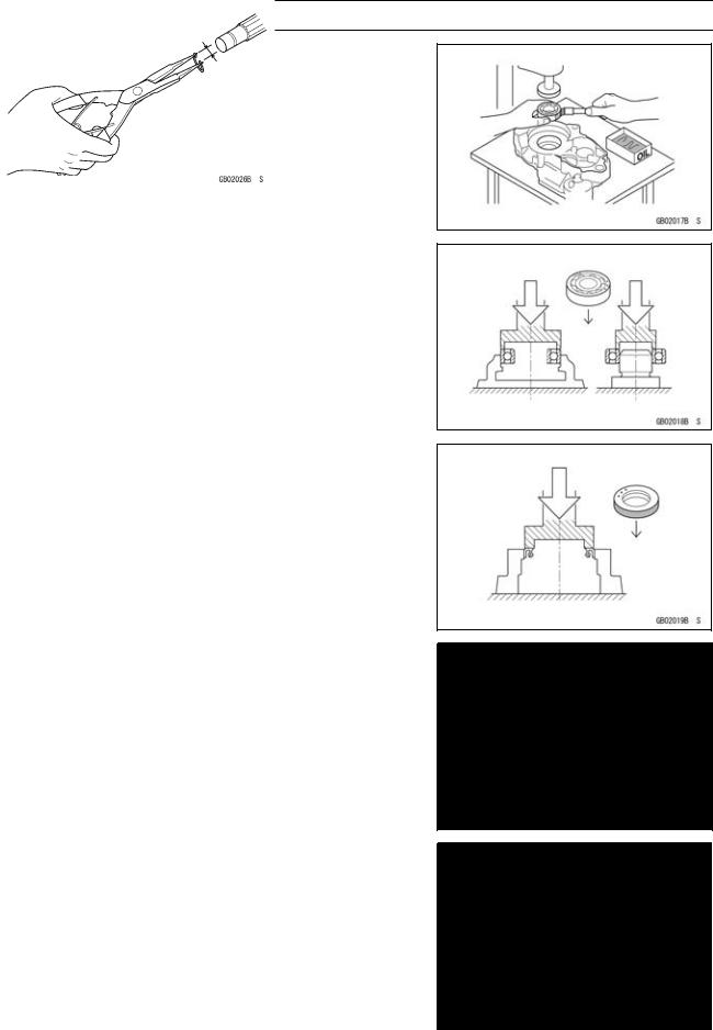
For items such as bearings or oil seals that must be pressed into place, apply small amount of oil to the contact area. Be sure to maintain proper alignment and use smooth movements when installing.
Ball Bearing and Needle Bearing
Do not remove pressed ball or needle unless removal is absolutely necessary. Replace with new ones whenever removed. Press bearings with the manufacturer and size marks facing out. Press the bearing into place by putting pressure on the correct bearing race as shown.
Pressing the incorrect race can cause pressure between the inner and outer race and result in bearing damage.
Oil Seal, Grease Seal
Do not remove pressed oil or grease seals unless removal is necessary. Replace with new ones whenever removed. Press new oil seals with manufacture and size marks facing out. Make sure the seal is aligned properly when installing.
Apply specified grease to the lip of seal before installing the seal.
Circlips, Cotter Pins
Replace the circlips or cotter pins that were removed with new ones. Take care not to open the clip excessively when installing to prevent deformation.
1-6 GENERAL INFORMATION
Before Servicing
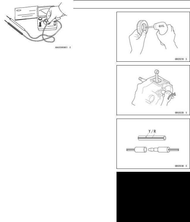
Lubrication
It is important to lubricate rotating or sliding parts during assembly to minimize wear during initial operation. Lubrication points are called out throughout this manual, apply the specific oil or grease as specified.
Direction of Engine Rotation
When rotating the crankshaft by hand, the free play amount of rotating direction will affect the adjustment. Rotate the crankshaft to positive direction (clockwise viewed from output side).
Electrical Wires
A two-color wire is identified first by the primary color and then the stripe color. Unless instructed otherwise, electrical wires must be connected to those of the same color.
Instrument
Use a meter that has enough accuracy for an accurate measurement. Read the manufacture’s instructions thoroughly before using the meter. Incorrect values may lead to improper adjustments.

GENERAL INFORMATION 1-7
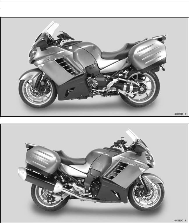
Model Identification
ZG1400A8F Left Side View
ZG1400A8F Right Side View
Frame Number |
|
Engine Number |
|
|
|
|
|
|
1-8 GENERAL INFORMATION
Model Identification
ZG1400A8F (United States and Canada) Left Side View
ZG1400A8F (United States and Canada) Right Side View
GENERAL INFORMATION 1-9
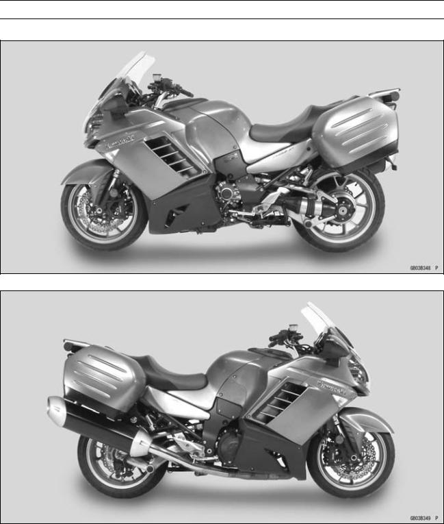
Model Identification
ZG1400B8F (United States and Canada) Left Side View
ZG1400B8F (United States and Canada) Right Side View

1-10 GENERAL INFORMATION
General Specifications
Items |
ZG1400A8F, ZG1400B8F |
Dimensions |
|
Overall Length |
2 270 mm (89.4 in.) |
Overall Width |
1 000 mm (39.4 in.) |
Overall Height/High Position |
1 290 mm (50.8 in.)/1 405 mm (55.3 in.) |
Wheelbase |
1 520 mm (59.8 in.) |
Road Clearance |
125 mm (4.9 in.) |
Seat Height |
815 mm (32.1 in.) |
Curb Mass: |
|
Front |
|
ZG1400A8F |
143 kg (315 lb) |
ZG1400B8F |
141 kg (311 lb) |
Rear |
|
ZG1400A8F |
165 kg (364 lb) |
ZG1400B8F |
163 kg (359 lb) |
Fuel Tank Capacity |
22 L (5.8 US gal) |
Performance |
|
Minimum Turning Radius |
3.2 m (10.5 ft) |
Engine |
|
Type |
4-stroke, DOHC, 4-cylinder |
Cooling System |
Liquid-cooled |
Bore and Stroke |
84.0 × 61.0 mm (3.3 × 2.4 in.) |
Displacement |
1 352 cm³ (82.5 cu in.) |
Compression Ratio |
10.7 : 1 |
Maximum Horsepower |
114.0 kW (155 PS) @8 800 r/min (rpm), |
|
(FR) 78.2 kW (106 PS) @8 000 r/min (rpm), |
|
(MY) 110.6 kW (150 PS) @8 800 r/min (rpm), |
|
(CA, CAL, US) – – – |
Maximum Torque |
136 N·m (13.9 kgf·m, 100 ft·lb) @6 200 r/min (rpm), |
|
(FR) 121 N·m (12.3 kgf·m, 89 ft·lb) @4 500 r/min (rpm), |
|
(MY) 139.0 N·m (14.1 kgf·m, 103 ft·lb) @6 200 r/min (rpm), |
|
(CA), (CAL), (US) – – – |
Carburetion System |
FI (Fuel injection), MIKUNI 40EIDW × 4 |
Starting System |
Electric starter |
Ignition System |
Battery and coil (transistorized) |
Timing Advance |
Electronically advanced (digital igniter in ECU) |
Ignition Timing |
From 10.6° BTDC @1 100 r/min (rpm) |
Spark Plug |
NGK CR9EIA-9 |
Cylinder Numbering Method |
Left to right, 1-2-3-4 |
Firing Order |
1-2-4-3 |
Valve Timing: |
|
Inlet: |
|
Open |
17° (BTDC) |
Close |
75° (ABDC) |
Duration |
272° |
|
|
|
GENERAL INFORMATION 1-11 |
General Specifications |
|
|
|
|
|
Items |
ZG1400A8F, ZG1400B8F |
Exhaust: |
|
Open |
52° (BBDC) |
Close |
22° (ATDC) |
Duration |
254° |
Lubrication System |
Forced lubrication (wet sump with cooler) |
Engine Oil: |
|
Type |
API SE, SF or SG |
|
API SH, SJ or SL with JASO MA |
Viscosity |
SAE10W-40 |
Capacity |
4.7 L (5.0 US qt) |
Drive Train |
|
Primary Reduction System: |
|
Type |
Gear |
Reduction Ratio |
1.556 (84/54) |
Clutch Type |
Wet multi disc |
Transmission: |
|
Type |
6-speed, constant mesh, return shift |
Gear Ratios: |
|
1st |
3.333 (50/15) |
2nd |
2.412 (41/17) |
3rd |
1.900 (38/20) |
4th |
1.545 (34/22) |
5th |
1.292 (31/24) |
6th |
1.074 (29/27) |
Final Drive System: |
|
Type |
Shaft drive |
Reduction Ratio |
2.036 (14/22 × 32/10) |
Overall Drive Ratio |
3.402 @Top gear |
Final Gear Case Oil: |
|
Grade |
API Service Classification: GL-5 hypoid gear oil |
Viscosity |
SAE90 (above 5°C), SAE80 (below 5°C) |
Capacity |
160 mL (5.4 US oz.) |
Frame |
|
Type |
Press backbone |
Caster (Rake Angle) |
26.1° |
Trail |
112 mm (4.4 in.) |
Front Tire: |
|
Type |
Tubeless |
Size |
120/70 ZR17 M/C (58 W) |
Rear Tire: |
|
Type |
Tubeless |
Size |
190/50 ZR17 M/C (73 W) |
|
|

1-12 GENERAL INFORMATION
General Specifications
Items |
ZG1400A8F, ZG1400B8F |
Rim Size: |
|
Front |
17 × 3.50 |
Rear |
17 × 6.00 |
Front Suspension: |
|
Type |
Telescopic fork (upside-down) |
Wheel Travel |
113 mm (4.4 in.) |
Rear Suspension: |
|
Type |
Swingarm (uni-trak - tetra lever) |
Wheel Travel |
136 mm (5.3 in.) |
Brake Type: |
|
Front |
Dual discs |
Rear |
Single disc |
Electrical Equipment |
|
Battery |
12 V 14 Ah |
Headlight: |
|
Type |
Semi-sealed beam |
Bulb: |
|
High |
12 V 60 W (quartz-halogen) × 2 |
Low |
12 V 55 W (quartz-halogen) × 2 |
Tail/Brake Light |
12 V 0.1/1.6 W (LED) |
Alternator: |
|
Type |
Three-phase AC |
Rated Output |
41.5 A/14 V @5 000 r/min (rpm) |
Specifications subject to change without notice, and may not apply to every country.
GENERAL INFORMATION 1-13
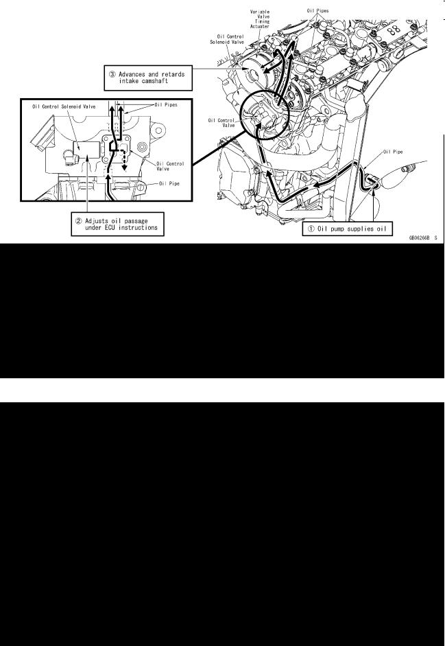
Technical Information-Variable Valve Timing
Overview
The camshafts that are provided in the engine determine the amount of valve overlap, which affects the engine’s characteristics. As a result, some engines are high-speed oriented while others are low -speed oriented. (Generally speaking, engines with a greater valve overlap are high-speed oriented.)
Ordinarily, it is difficult for a given engine to deliver both high-speed and low-speed characteristics. However, the variable valve timing mechanism steplessly varies the amount of valve overlap in accordance with engine speed and throttle position sensor data. Thus, it produces power characteristics that suit running conditions, from the lowto the high-speed range.
Operation
Control Oil Flow
1-14 GENERAL INFORMATION
Technical Information-Variable Valve Timing
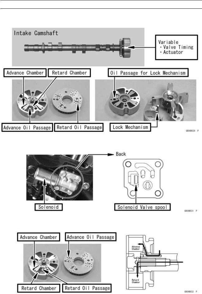
Components
•Variable Valve Timing Actuator
•Oil Control Valve Solenoid Valve
Oil Flow of Parts
•Variable Valve Timing Actuator
GENERAL INFORMATION 1-15
Technical Information-Variable Valve Timing
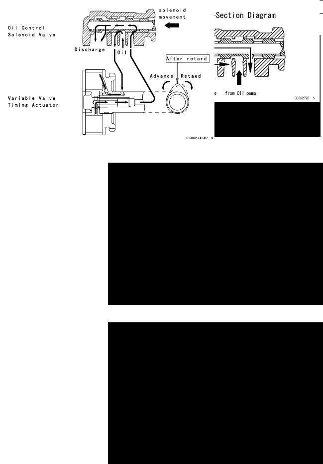
•Oil Control Solenoid Valve
Oil Flow during Control
•Retard Position
•Advance Position
1-16 GENERAL INFORMATION
Technical Information-Variable Valve Timing
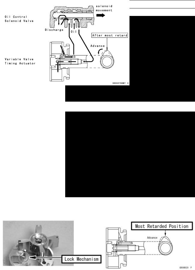
•Neutral Position
•Most Retarded Position
Lock Mechanism
•During idle, the lock mechanism locks the camshaft at the most retarded position.
•When the engine is stopped, the force of the spring returns the solenoid valve to its most retarded position, thus placing the camshaft in the most retarded position.
GENERAL INFORMATION 1-17
Technical Information-Electrical Windshield
Overview
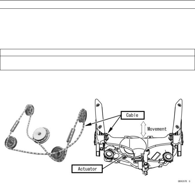
Wind protection for rider and passenger is based on a supersport-style design philosophy. Aerodynamically curving wind around the riders reduces buffeting that occurs when wind curls around windshield that simply "block" the wind.
This model is equipped with the electrically adjustable windshield. The cable connects the windshield with the actuator that is powered by an electric motor. When the adjusting button on the handlebar is pushed, the actuator reels off the cable to change windshield height up or down.
CAUTION
Make sure all body parts, clothing or other objects are not near the movable parts of the windshield when it is being moved to avoid such items from becoming pinched or caught.
Electric Adjustable Windscreen
1-18 GENERAL INFORMATION
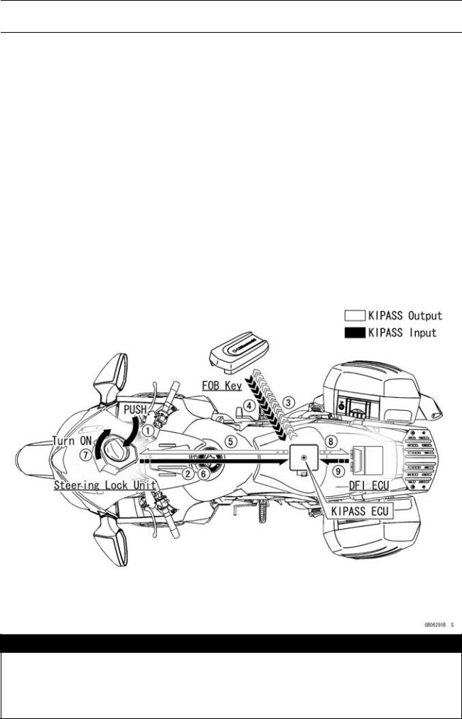
Technical Information-KIPASS (Kawasaki’s Intelligent Proximity Activation Start
System)
Overview
•For better user convenience, a system to wirelessly start the engine is used instead of the conventional mechanical key. This frees the rider from handling the ignition key, a helpful feature in the rain or after putting on gloves.
•For improved security, a theft deterrence system that involves reciprocal encryption and authentication among multiple units is used instead of a system based on an immobilizer.
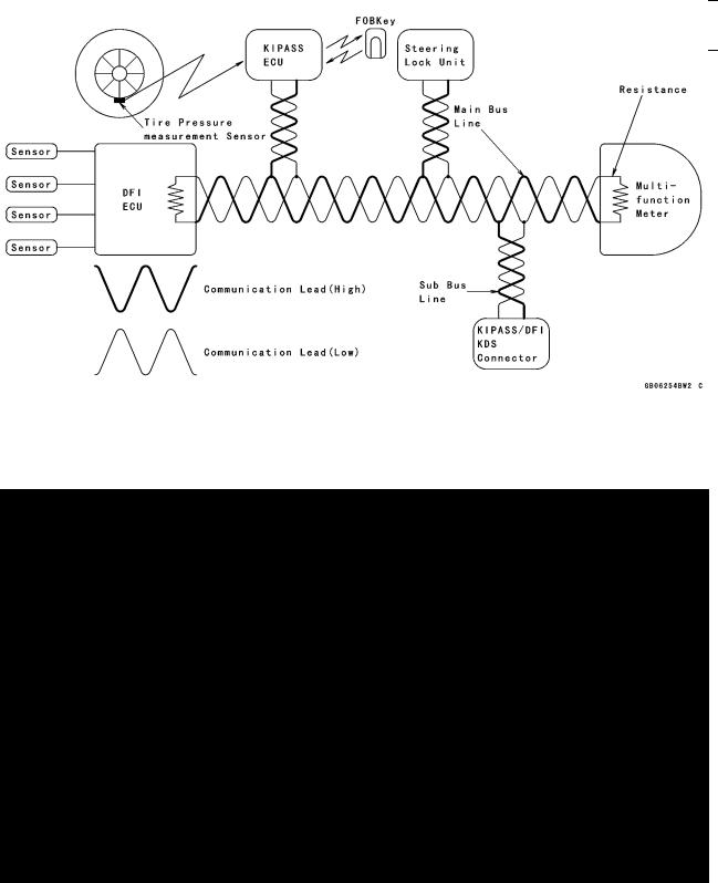
•Tire pressure measurement sensors are used for monitoring the air pressures of the front and rear tires at regular intervals and alerting the rider in case an abnormal condition is detected while the vehicle is running.
•A CAN (Controller Area Network) communication system is used for transmitting and receiving system encryption and authentication data, diagnosis data, and meter indication data consisting of various types of information. This ensures high-volume, high-speed communication while enabling
a significant reduction in wiring, which ensures reliability.
KIPASS: Kawasaki’s Intelligent Proximity Activation Start System
This product uses MISTY, an encryption algorithm developed by Mitsubishi Electric Corporation.

 WARNING
KIPASS may interfere with the operation of certain medical device such as implanted pacemakers and implanted cardiac defibrillators. The FOB key or the antenna of KIPASS ECU must be kept more than 22 cm (9 in.) from these type of medical devices. Operators with medical devices such as implanted pacemakers and implanted cardiac defibrillators should consult with their doctors.
GENERAL INFORMATION 1-19
Technical Information-KIPASS (Kawasaki’s Intelligent Proximity Activation Start
System)
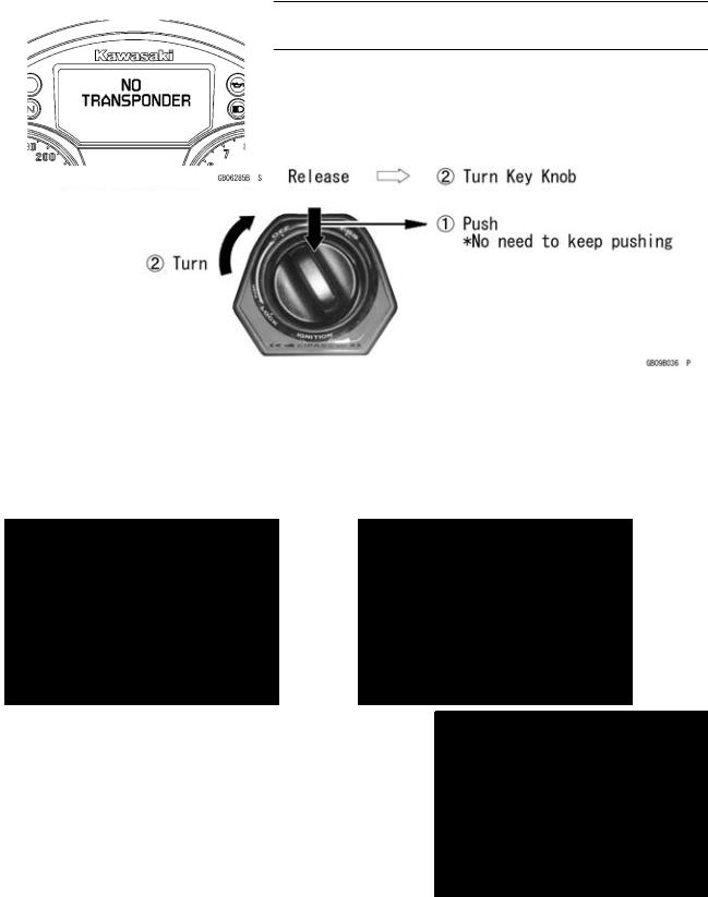
Key Knob Operation
•The key knob consists of ON, OFF, FSS, and LOCK positions.
*FSS indicates the following positions in which the key knob can be released during operation: F = fuel tank, S = seat, and S = saddlebag.
Starting the Engine
•The key knob can be turned to the ON position when the key knob symbol appears on the LCD meter. Then, the letters "Kawasaki" will appear for 3 seconds on the LCD screen.
○When the engine operates normally, the turn signal lights in the meter will flash (answer-back) twice to inform the rider of normal operation.
(FOB key, steering lock, and DFI ECU authentication)
Running
•The system tries to detect the FOB each time the vehicle goes above 20 km/h.
*The system will not detect the FOB key if it cannot detect the vehicle speed, such as in case of a meter malfunction.
•If the system cannot detect the FOB key, an error message will appear on the meter. The message will disappear if the system can detect the FOB key.
*If the system is unable to authenticate, it will maintain authentication communication until the ignition is turned OFF.
•The operation range of the FOB key could change because it uses weak radiowave signals. Thus, an error message could appear even if the FOB key is within the use range.
*This will not stop the engine after it is started.
1-20 GENERAL INFORMATION
Technical Information-KIPASS (Kawasaki’s Intelligent Proximity Activation Start
System)
Vehicle Stopped
•The system performs authentication of the FOB key as the key knob is turned OFF. If the FOB key is not there, a warning message will appear on the meter.
•If the authentication of the FOB key is completed as the key knob is turned OFF, the meter will provide an answer-back once. Then, the key knob becomes locked 5 seconds later.
*If the FOB key is lost, the key knob becomes locked 10 seconds later.
•If the key knob is left unlocked, the vehicle can be moved even if the FOB key is not in the rider’s possession.
*Make sure to set the key knob to the lock position before leaving the vehicle.
CAN Communication
•CAN is a type of serial communication proposed by Robert Bosch GmbH, a European manufacturer of electronic components. Offering high-speed and high-safety communication, this system was
launched in 1986 to be used as a LAN network linking onboard ECUs (Electric Control Units). *At Kawasaki, this system is already being used on the ZX1400A/B.
1.Uses two communication lines (called bus lines, consisting of high and low voltages) and changes their electric potentials to transmit and receive data.
2.Uses high-speed CAN to communicate at high speeds. Because it can exchange large volumes of data within a short time, it is also highly reliable.
3.CAN communication helps reduce the number of wiring harnesses.
CAN: Controller Area Network
CAN Communication System
 Loading...