


ER-6N
Table of contents
 Loading...
ER-6n
Motorcycle
Service Manual
http://mototh.com

http://mototh.com
This quick reference guide will assist
you in locating a desired topic or pro-
cedure.
•Bend the pages back to match the
black tab of the desired chapter num-
ber with the black tab on the edge at
each table of contents page.
•Refer to the sectional table of contents
for the exact pages to locate the spe-
cific topic required.
Quick Reference Guide
General Information 1 j
Periodic Maintenance 2 j
Fuel System (DFI) 3 j
Cooling System 4 j
Engine Top End 5 j
Clutch 6 j
Engine Lubrication System 7 j
Engine Removal/Installation 8 j
Crankshaft/Transmission 9 j
Wheels/Tires 10 j
Final Drive 11 j
Brakes 12 j
Suspension 13 j
Steering 14 j
Frame 15 j
Electrical System 16 j
Appendix 17 j
http://mototh.com

http://mototh.com

ER-6n
Motorcycle
Service Manual
All rights reserved. No parts of this publication may be reproduced, stored in a retrieval system, or
transmitted in any form or by any means, electronic mechanical photocopying, recording or otherwise,
without thepriorwrittenpermissionofQualityDivision/ConsumerProducts&Machinery Company/Kawasaki
Heavy Industries, Ltd., Japan.
No liability can be accepted for any inaccuracies or omissions in this publication, although every possible
care has been taken to make it as complete and accurate as possible.
The right is reserved to make changes at any time without prior notice and without incurring an obligation
to make such changes to products manufactured previously. See your Motorcycle dealer for the latest
information on product improvements incorporated after this publication.
All information contained in this publication is based on the latest product information available at the time
of publication. Illustrations and photographs in this publication are intended for reference use only and may
not depict actual model component parts.
© 2005 Kawasaki Heavy Industries, Ltd. First Edition (1) : Aug. 5, 2005 (K)
http://mototh.com

LIST OF ABBREVIATIONS
A ampere(s) lb pound(s)
ABDC after bottom dead center
m
meter(s)
AC
alternating current min
minute(s)
ATDC after top dead center
N
newton(s)
BBDC before bottom dead center Pa pascal(s)
BDC bottom dead center PS horsepower
BTDC before top dead center psi pound(s) per square inch
°C degree(s) Celsius r revolution
DC direct current rpm revolution(s) per minute
F farad(s) TDC top dead center
°F degree(s) Fahrenheit TIR total indicator reading
ft foot, feet V volt(s)
g gram(s) W watt(s)
h
hour(s) Ω ohm(s)
L
liter(s)
Read OW
NER’S MANUAL before operating.
http://mototh.com
Foreword
This manual is designed primarily for use by
trained mechanics in a properly equipped shop.
However,itcontainsenough detail and basic in-
formationto make it useful tothe owner who de-
siresto perform his own basic maintenanceand
repair work. A basic knowledge of mechanics,
the proper use of tools, and workshop proce-
dures must be understood in order to carry out
maintenance and repair satisfactorily. When-
ever the owner has insufficient experience or
doubts his ability to do the work, all adjust-
ments, maintenance, and repair should be car-
ried out only by qualified mechanics.
In order to perform the work efficiently and
to avoid costly mistakes, read the text, thor-
oughly familiarize yourself with the procedures
beforestarting work, and then do the work care-
fully in a clean area. Whenever special tools or
equipment are specified, do not use makeshift
tools or equipment. Precision measurements
can only be made if the proper instruments are
used, and the use of substitute tools may ad-
versely affect safe operation.
For the duration of the warranty period,
we recommend that all repairs and scheduled
maintenance be performed in accordance with
thisservice manual. Anyowner maintenance or
repair procedure not performed in accordance
with this manual may void the warranty.
To get the longest life out of your vehicle:
•
Follow the Periodic Maintenance Chart in the
Service Manual.
•
Be alert for problems and non-scheduled
maintenance.
•
Use proper tools and genuine Kawasaki Mo-
torcycle parts. Special tools, gauges, and
testers that are necessary when servicing
Kawasaki motorcycles are introduced by the
Service Manual. Genuine parts provided as
spare parts are listed in the Parts Catalog.
•
Follow the procedures in this manual care-
fully. Don’t take shortcuts.
•
Rememberto keep completerecords ofmain-
tenance and repair with dates and any new
parts installed.
How to Use This M anual
In preparingthis manual, we divided the prod-
uct into its major systems. These systems be-
came the manual’s chapters. All information
for a particular system from adjustment through
disassembly and inspection is located in a sin-
gle chapter.
The Quick Reference Guide shows you all
of the product’s system and assists in locating
their chapters. Each chapter in turn has its own
comprehensive Table of Contents.
The Periodic Maintenance Chart is located in
the Periodic Maintenance chapter. The chart
gives a time schedule for required maintenance
operations.
If you want spark plug information, for exam-
ple, go to the Periodic Maintenance Chart first.
The chart tells you how frequently to clean and
gap the plug. Next, use the Quick Reference
Guide to locate the Periodic Maintenance chap-
ter. Then, use the Table of Contents on the first
page of the chapter to find the Spark Plug sec-
tion.
Whenever you see these WARNING and
CAUTION symbols, heed their instructions!
Always follow safe operating and maintenance
practices.
WARNING
This warning symbol identifies special
instructions or procedures which, if not
correctly followed, could result in per-
sonal injury, or loss of life.
CAUTION
This caution symbol identifies special
instructions or procedures which, if not
strictly observed, could result in dam-
age to or destruction of equipment.
This manual contains four more symbols (in
additionto WARNINGandCAUTION) whichwill
help you distinguish different types of informa-
tion.
http://mototh.com

NOTE
○
This note symbol indicates points of par-
ticular interest for more efficient and con-
venient operation.
•
Indicates a procedural step or work to be
done.
○
Indicates a procedural sub-step or how to do
the work of the procedural step it follows. It
also precedes the text of a NOTE.
Indicates a conditional step or what action to
takebased on the results of the test or inspec-
tion in the procedural step or sub-step it fol-
lows.
In most chapters an exploded view illustration
of the system components follows the Table of
Contents. In these illustrations you will find the
instructions indicatingwhich parts require spec-
ified tightening torque, oil, grease or a locking
agent during assembly.
http://mototh.com

GENERAL INFORMATION 1-1
1
General Information
Table of Contents
Before Servicing ..................................................................................................................... 1-2
Model Identification................................................................................................................. 1-7
General Specifications............................................................................................................ 1-8
Technical Information - Cassette Type Transmission............................................................. 1-11
Technical Information - Inlet Air Pressure Sensor ................................................................. 1-12
Unit Conversion Table............................................................................................................ 1-13
http://mototh.com

1-2 GENERAL INFORMATION
Before Servicing
Before starting to perform an inspection service or carry out a disassembly and reassembly opera-
tion on a motorcycle, read the precautions given below. To facilitate actual operations, notes, illustra-
tions, photographs, cautions, and detailed descriptions have been included in each chapter wherever
necessary. This section explains the items that require particular attention during the removal and
reinstallation or disassembly and reassembly of general parts.
Especially note the following:
Battery Ground
Before completing any service on the motorcycle, discon-
nect the battery wires from the battery to prevent the engine
from accidentally turning over. Disconnect the ground wire
(–) first and then the positive (+). When completed with the
service, first connect the positive (+) wire to the positive (+)
terminal of the battery then the negative (–) wireto the neg-
ative terminal.
Edges of Parts
Lift large or heavy parts wearing gloves to prevent injury
from possible sharp edges on the parts.
Solvent
Use a high-flush point solvent when cleaning parts. High
-flush point solvent should be used according to directions
of the solvent manufacturer.
Cleaning Vehicle before Disassembly
Clean the vehicle thoroughly before disassembly. Dirt or
otherforeign materials entering into sealedareas during ve-
hicle disassembly can cause excessive wear and decrease
performance of the vehicle.
http://mototh.com

GENERAL INFORMATION 1-3
Before Servicing
Arrangement and Cleaning of Removed Parts
Disassembled parts are easy to confuse. Arrange the
parts according to the order the parts were disassembled
and clean the parts in order prior to assembly.
Storage of Removed Parts
After all the partsincluding subassembly parts have been
cleaned, store the parts in a clean area. Put a clean cloth
or plastic sheet over the parts to protect from any foreign
materials that may collect before re-assembly.
Inspection
Reuse of worn or damaged parts may lead to serious ac-
cident. Visually inspect removed partsfor corrosion, discol-
oration, or other damage. Refer to the appropriate sections
of this manual for service limits on individual parts. Replace
the parts if any damage has been found or if the part is be-
yond its service limit.
Replacement Parts
Replacement parts must be KAWASAKI genuine or
recommended by KAWASAKI. Gaskets, O-rings, oil seals,
grease seals, circlips or cotter pins must be replaced with
new ones whenever disassembled.
Assembly Order
In most cases assembly order is the reverse of disassem-
bly, however, if assembly order is provided in this Service
Manual, follow the procedures given.
http://mototh.com

1-4 GENERAL INFORMATION
Before Servicing
Tightening Sequence
Generally, when installing a part with several bolts, nuts,
or screws, start them all in their holes and tighten them to
a snug fit. Then tighten them according to the specified s e-
quence to prevent case warpage or deformation which can
lead to malfunction. Conversely when loosening the bolts,
nuts, or screws, first loosen all of them by about a quar-
ter turn and then remove them. If the specified tightening
sequence is not indicated, tighten the fasteners alternating
diagonally.
Tightening Torque
Incorrect torque applied to a bolt, nut, or screw may
lead to serious damage. Tighten fasteners to the specified
torque using a good quality torque wrench. Often, the
tightening sequence is followed twice-initial tightening and
final tightening with torque wrench.
Force
Use common sense during disassembly and assembly,
excessive forcecan cause expensive or hard to repair dam-
age. When necessary, remove screws that have a non
-permanent locking agent applied using an impact driver.
Use a plastic-faced mallet whenever tapping is necessary.
Gasket, O-ring
Hardening, shrinkage, or damage of both gaskets
and O-rings after disassembly can reduce sealing per-
formance. Remove old gaskets and clean the sealing
surfaces thoroughly so that no gasket material or other
material remains. Install new gaskets and replace used
O-rings when re-assembling
Liquid Gasket, Non-permanent Locking Agent
For applications that require Liquid Gasket or a
Non-permanent Locking Agent, clean the surfaces so
that no oil residue remains before applying liquid gasket or
non-permanent locking agent. Do not apply them exces-
sively. Excessive application can clog oil passages and
cause serious damage.
http://mototh.com
GENERAL INFORMATION 1-5
Before Servicing
Press
For items such as bearings or oil seals that must be
pressed into place, apply small amount of oil to the con-
tact area. Be sure to maintain proper alignment and use
smooth movements when installing.
Ball Bearing and Needle Bearing
Do not remove pressed ball or needle unless removal is
absolutely necessary. Replace with new ones whenever
removed. Press bearings with the manufacturer and size
marks facing out. Press the bearing into place by putting
pressure on the correct bearing race as s hown.
Pressing the incorrect race can cause pressure between
the inner and outer race and result in bearing damage.
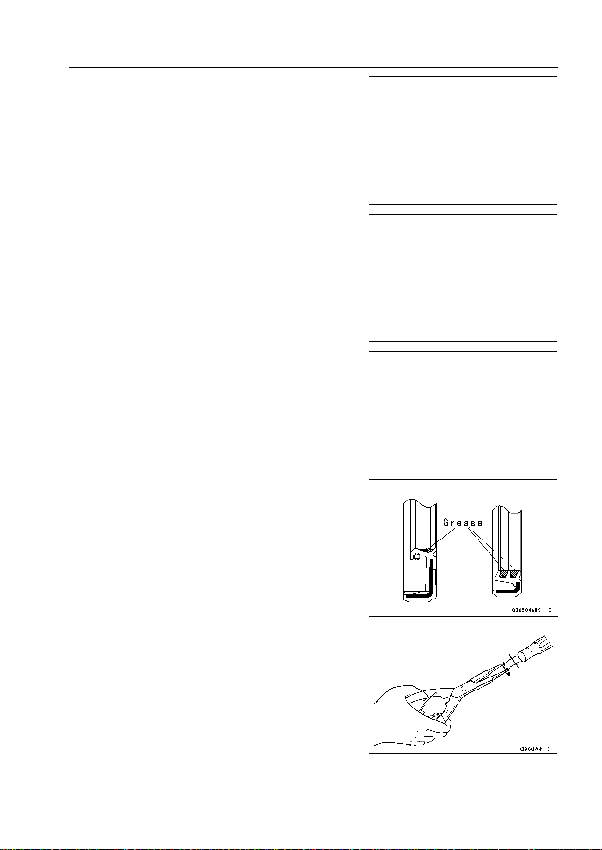
Oil Seal, Grease Seal
Donot removepressed oil orgrease sealsunless removal
is necessary. Replace with new ones whenever removed.
Press new oil seals with manufacture and size marks facing
out. Make sure the seal is aligned properly when installing.
Apply specified grease to the lip of seal before installing
the seal.
Circlips, Cotter Pins
Replacecirclips orcotter pins thatwere removedwith new
ones. Take care not to open the clip excessively when in-
stalling to prevent deformation.
http://mototh.com
1-6 GENERAL INFORMATION
Before Servicing
Lubrication
It is important to lubricate rotating or sliding parts during
assembly to minimize wear during initial operation. Lubri-
cation points are called out throughout this manual, apply
the specific oil or grease as specified.
Direction of Engine Rotation
When rotating the crankshaft by hand, the free play
amount of rotating direction will affect the adjustment. Ro-
tate the crankshaft to positive direction (clockwise viewed
from output side).
Electrical Wires
A two-color wire is identified first by the primary color and
then the stripe color. Unless instructed otherwise, electrical
wires must be connected to those of the same color.
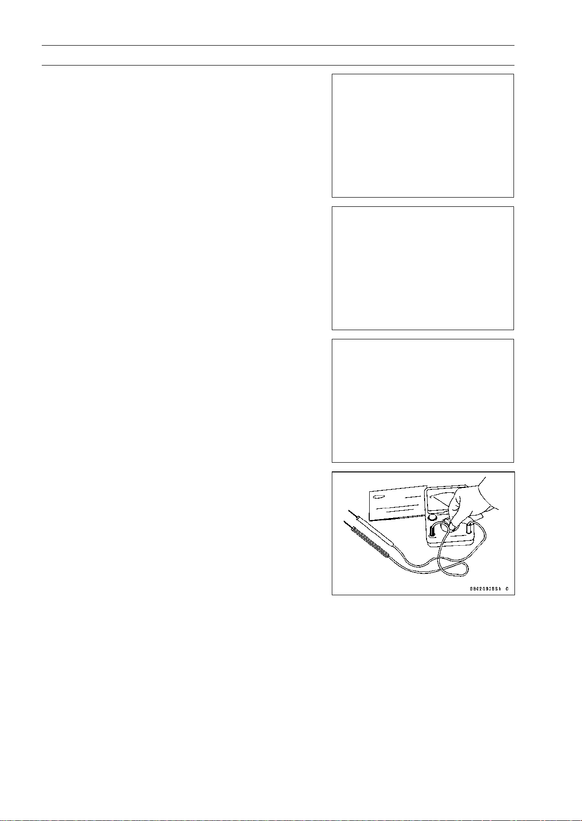
Instrument
Use a meter that has enough accuracy for an accurate
measurement. Read the manufacture’s instructions thor-
oughly before using the meter. Incorrect values may lead
to improper adjustments.
http://mototh.com

GENERAL INFORMATION 1-7
Model Identification
ER650A6F/ER650A6S Left Side View
ER650A6F/ER650A6S Right Side View
ER650A6F: Australia, Malaysia
ER650A6S: Europe
http://mototh.com

1-8 GENERAL INFORMATION
General Specifications
Items ER650A6F/ER650A6S
Dimensions
Overall Length 2 100 mm (82.7 in.)
Overall Width 760 mm (29.9 in.)
Overall Height 1 095 mm (43.1 in.)
Wheelbase 1 405 mm (55.3 in.)
Road Clearance 140 mm (5.5 in.)
Seat Height 785 mm (30.9 in.)
Dry Mass 174 kg (383.7 lb)
Curb Mass:
Front
98 kg (216.1 lb)
Rear 98 kg (216.1 lb)
Fuel Tank Capacity 15.5 L (4.1 US gal.)
Performance
Minimum Turning Radius 2.7 m (8.9 ft)
Engine
Type 4-stroke, DOHC, 2-cylinder
Cooling System Liquid-cooled
Bore and Stroke 83 × 60 mm (3.3 × 2.4 in.)
Displacement
649 cm³ (39.60 cu in.)
Compression Ratio 11.3 : 1
Maximum Horsepower 53 kW (72 PS) @8 500 r/min (rpm),
Maximum Torque 66 N·m (6.7 kgf·m, 49 ft·lb) @7 000 r/min (rpm),
Carburetion System FI (Fuel Injection) KEIHIN TTK38 × 2
Starting System Electric starter
Ignition System Battery and coil (transistorized)
Timing Advan
ce
Electronically advanced (digital igniter)
Ignition Timing
From 10° BTDC @1 300 r/min (rpm) to 35° BTDC @4 800
r/min (rpm)
Spark Plug NGK CR9EIA-9
Cylinder Numbering Method Left to right, 1-2
Firing Order 1-2
Valve Timing:
Inlet:
Open 31° BTDC
Close 61° ABDC
Duration 272°
Exhaust:
Open 50° BBDC
Close 30° ATDC
Duration 260°
Lubrication System Forced lubrication (semi-dry sump)
Engine Oil:
Type
API SE, SF or SG
API SH, SJ or SL with JASO MA
http://mototh.com

GENERAL INFORMATION 1-9
General Specifications
Items ER650A6F/ER650A6S
Viscosity SAE 10W-40
Capacity 2.4L(2.5USqt)
Drive Train
Primary Reduction System:
Type Gear
Reduction Ratio 2.095 (88/42)
Clutch Type
Wet multi disc
Transmission:
Type 6-speed, constant mesh, return shift
Gear Ratios:
1st
2.438 (39/16)
2nd 1.714 (36/21)
3rd 1.333 (32/24)
4th 1.111 (30/27)
5th 0.966 (28/29)
6th
0.852 (23/27)
Final Drive System:
Type Chain drive
Reduction Ratio 3.067 (46/15)
Overall Drive Ratio 5.473 @Top gear
Frame
Type Tubular, diamond
Caster (Rake Angle) 24.5°
Trail 102 mm (4.0 in.)
Front Tire:
Type Tubeless
Size 120/70 ZR17 M/C (58W)
Rim Size
17 × 3.50
Rear Tire:
Type Tubeless
Size 160/60 ZR17 M/C (69W)
Rim Size 17 × 4.50
Front Suspension:
Type
Telescopic fork
Wheel Travel
120 mm (4.7 in.)
Rear Suspension:
Type Swingarm
Wheel Travel 125 mm (4.9 in.)
Brake Type:
Front Dual discs
Rear
Single disc
Electrical Equipment
Battery 12 V 10 Ah
http://mototh.com

1-10 GENERAL INFORMATION
General Specifications
Items ER650A6F/ER650A6S
Headlight:
Type Semi-sealed beam
Bulb 12V55W×2/55W(Hi/Lo)
Tail/Brake Light 12 V 5/21 W
Alternator:
Type Three-phase AC
Rated Output 24 A/14 V @5 000 r/min (rpm)
Specifications are subject to change without notice, and may not apply to every country.
http://mototh.com

GENERAL INFORMATION 1-11
Technical Information - Cassette Type Transmission
Cassette Type Transmission
The transmission of the current model is unable to be removed without disassembling upper and
lower crankcase halves.
The ER650A enables transmission to be removed from the right side of engine as an assy, without
disassembling crankcase halves (see Transmission Assy Removal in the Crankshaft/Transmission
chapter).
Transmission Assy:
Drive Shaft [A]
Output Shaft [B]
Shift Rods [C]
Shift Dram [D]
Shift Forks [E]
Transmission Ca se [F]
http://mototh.com

1-12 GENERAL INFORMATION
Technical Information - I nlet Air Pressure Sensor
Atmospheric pressure sensor and camshaft position sensor are not equipped with the ER650A. As
a substitute of these sensors above, the ER650A recognizes atmospheric pressure and intake stroke
of #1 by the signal of inlet air pressure sensor.
The ECU detects atmospheric pressure when the ignition is switched ON. While the engine is run-
ning, theECU also presumes atmospheric pressureby analyzing the waveform of boostpressure over
fixed period. The intake stroke is recognized by waveform of boost pressure, therefore the system
can recognize the difference of each stroke.
http://mototh.com
GENERAL INFORMATION 1-13
Unit Conversion Table
Prefixes for Units:
Prefix Symbol Power
mega M ×1000000
kilo k × 1 000
centi c ×0.01
milli m × 0.001
micro µ × 0.000001
Units of Mass:
kg ×2.205=lb
g × 0.03527 = oz
Units of Volume:
L × 0.2642 =
gal (US)
L × 0.2200 =
gal (imp)
L × 1.057 = qt (US)
L × 0.8799 = qt (imp)
L × 2.113 = pint (US)
L × 1.816 = pint (imp)
mL × 0.03381 =
oz (US)
mL × 0.02816 =
oz (imp)
mL × 0.06102 = cu in
Units of Force:
N × 0.1020 = kg
N × 0.2248 = lb
kg ×9.807=N
kg ×2.205=lb
Units of Length:
km × 0.6214 = mile
m × 3.281 = ft
mm × 0.03937 = in
Units of Torque:
N·m × 0.1020 = kgf·m
N·m × 0.7376 = ft·lb
N·m × 8.851 = in·lb
kgf·m
× 9.807 = N·m
kgf·m
×7.233=
ft·lb
kgf·m
× 86.80 = in·lb
Units of Pressure:
kPa × 0.01020 =
kgf/cm²
kPa × 0.1450 = psi
kPa × 0.7501 = cmHg
kgf/cm² × 98.07 = kPa
kgf/cm² × 14.22 = psi
cmHg × 1.333 = kPa
Units of Speed:
km/h × 0.6214 = mph
Units of Power:
kW × 1.360 =
PS
kW × 1.341 = HP
PS × 0.7355 = kW
PS × 0.9863 = HP
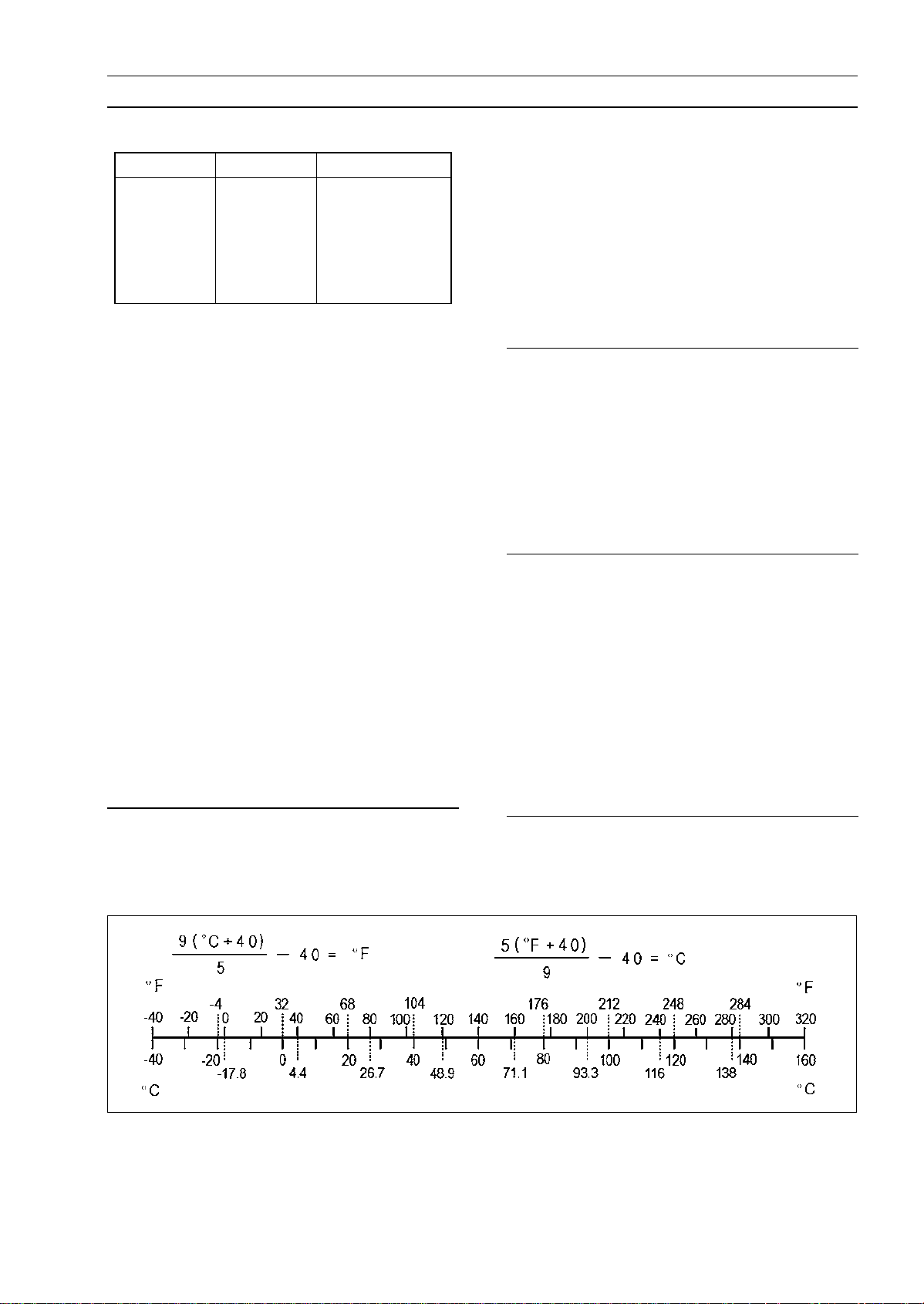
Units of Temperature:
http://mototh.com

http://mototh.com

PERIODIC MAINTENANCE 2-1
2
Periodic Maintenance
Table of Contents
Periodic Maintenance Chart................................................................................................... 2-3
Torque and Locking Agent...................................................................................................... 2-6
Specifications ......................................................................................................................... 2-11
Special Tools.......................................................................................................................... 2-13
Periodic Maintenance Procedures.......................................................................................... 2-14
Fuel System (DFI)................................................................................................................ 2-14
Fuel Hose Inspection (fuel leak, damage, installation condition)...................................... 2-14
Throttle Control System Inspection................................................................................... 2-14
Idle Speed Inspection ....................................................................................................... 2-15
Idle Speed Adjustment...................................................................................................... 2-15
Air Cleaner Element Cleaning........................................................................................... 2-16
Engine Vacuum Synchronization Inspection..................................................................... 2-17
Cooling System.................................................................................................................... 2-19
Coolant Level Inspection................................................................................................... 2-19
Radiator Hose and Pipe Inspection (coolant leak, damage, installation condition) ......... 2-20
Air Suction System .............................................................................................................. 2-20
Air Suction System Damage Inspection............................................................................ 2-20
Engine Top End................................................................................................................... 2-20
Valve Clearance Inspection .............................................................................................. 2-20
Valve Clearance Adjustment............................................................................................. 2-22
Clutch................................................................................................................................... 2-25
Clutch Operation Inspection.............................................................................................. 2-25
Wheels/Tires........................................................................................................................ 2-25
Air Pressure Inspection..................................................................................................... 2-25
Wheel/Tire Damage Inspection......................................................................................... 2-26
Tire Tread Wear, Abnormal Wear Inspection.................................................................... 2-26
Wheel Bearing Damage Inspection .................................................................................. 2-27
Drive Train........................................................................................................................... 2-27
Drive Chain Lubrication Condition Inspection................................................................... 2-27
Drive Chain Slack Inspection............................................................................................ 2-28
Drive Chain Slack Adjustment .......................................................................................... 2-28
Wheel Alignment Inspection ............................................................................................. 2-29
Drive Chain Wear Inspection............................................................................................ 2-30
Chain Guide Inspection..................................................................................................... 2-30
Brake System ...................................................................................................................... 2-31
Brake Fluid Leak (Brake Hose and Pipe) Inspection........................................................ 2-31
Brake Hose Damage and Installation Condition Inspection.............................................. 2-31
Brake Operation Inspection .............................................................................................. 2-31
Brake Fluid Level Inspection............................................................................................. 2-32
Brake Pad Wear Inspection.............................................................................................. 2-33
Brake Light Switch Operation Inspection.......................................................................... 2-33
Suspensions........................................................................................................................ 2-34
Front Forks/Rear Shock Absorber Operation Inspection.................................................. 2-34
Front Fork Oil Leak Inspection.......................................................................................... 2-34
Rear Shock Absorber Oil Leak Inspection........................................................................ 2-34
Steering System..................................................................................................................2-35
http://mototh.com

2-2 PERIODIC MAINTENANCE
Steering Play Inspection................................................................................................... 2-35
Steering Play Adjustment.................................................................................................. 2-35
Steering Stem Bearing Lubrication................................................................................... 2-36
Electrical System................................................................................................................. 2-37
Spark Plug Condition Inspection....................................................................................... 2-37
Lights and Switches Operation Inspection........................................................................ 2-38
Headlight Aiming Inspection ............................................................................................. 2-40
Sidestand Switch Operation Inspection............................................................................ 2-41
Engine Stop Switch Operation Inspection......................................................................... 2-42
Others.................................................................................................................................. 2-43
Chassis Parts Lubrication................................................................................................. 2-43
Bolts, Nuts and Fasteners Tightness Inspection............................................................... 2-44
Replacement Parts .............................................................................................................. 2-45
Air Cleaner Element Replacement.................................................................................... 2-45
Engine Oil Change............................................................................................................ 2-45
Oil Filter Replacement ...................................................................................................... 2-46
Fuel Hose Replacement ................................................................................................... 2-46
Coolant Change................................................................................................................ 2-47
Radiator Hose and O-ring Replacement........................................................................... 2-50
Brake Hose and Pipe Replacement.................................................................................. 2-51
Brake Fluid Change.......................................................................................................... 2-51
Master Cylinder Rubber Parts Replacement .................................................................... 2-53
Caliper Rubber Parts Replacement.................................................................................. 2-54
Spark Plug Replacement.................................................................................................. 2-56
http://mototh.com
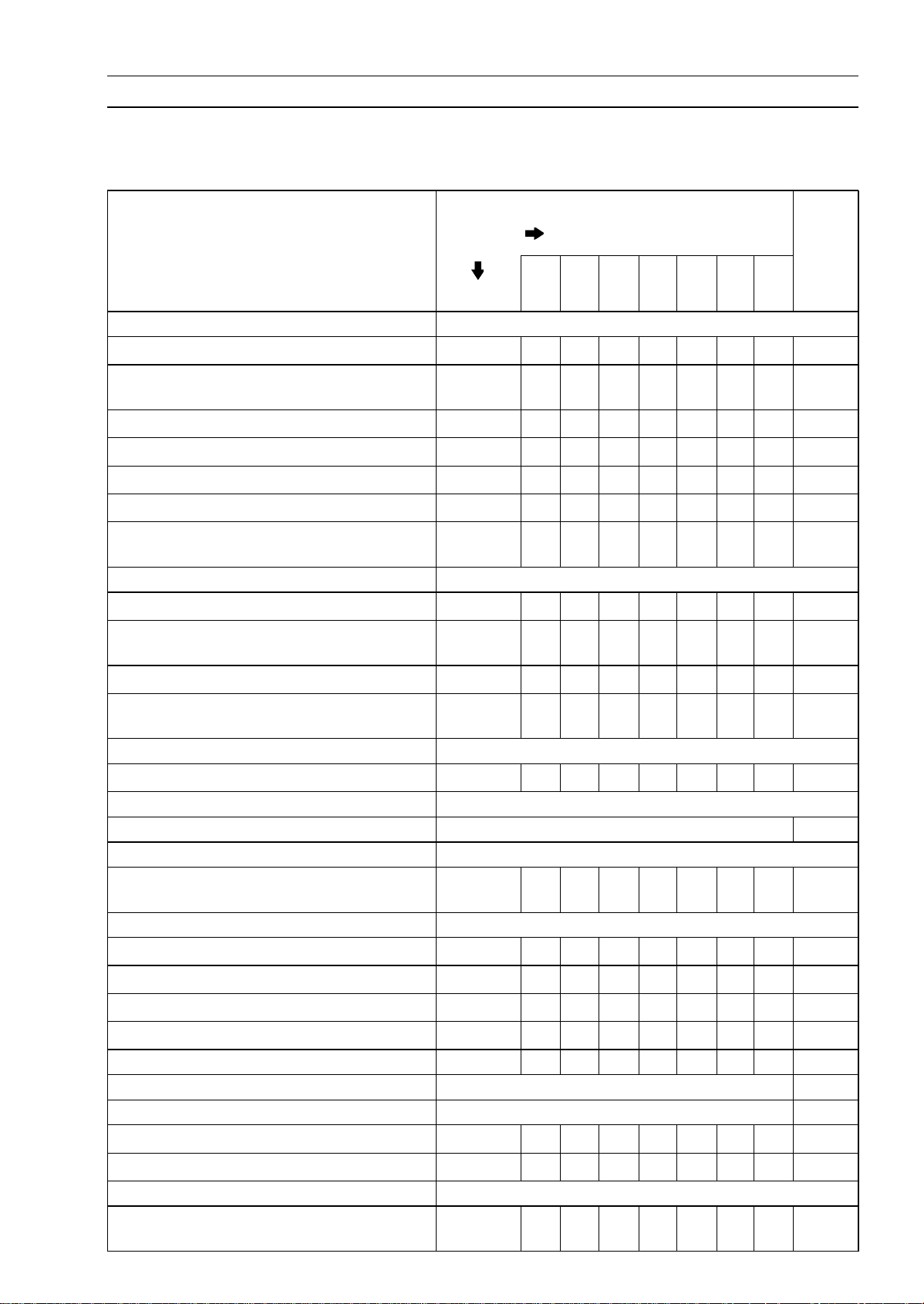
PERIODIC MAINTENANCE 2-3
Periodic Maintenance Chart
The scheduled maintenance must be done in accordance with this chart to keep the motorcycle in
good running condition.The initial m aintenance is vitally important and must not be neglected.
Periodic Inspection
FREQUENCY Whichever
comes
first
* ODOMETER READING
× 1 000 km
(× 1 000 mile)
1 6 12 18 24 30 36
INSPECTION Every (0.6) (4) (7.5) (12) (15) (20) (24)
See
Page
Fuel System
Air cleaner element - clean
• • •
2-16
Throttle control system (play, smooth
return, no drag) - inspect
year
• • • •
2-14
Engine vacuum synchronization - inspect
• • •
2-17
Idle speed - inspect
• • • •
2-15
Fuel leak (fuel hose and pipe) - inspect year
• • • •
2-14
Fuel hose and pipe damage - inspect year
• • • •
2-14
Fuel hose and pipe installation condition
- inspect
year
• • • •
2-14
Cooling System
Coolant level - inspect
• • • •
2-19
Coolant leak (radiator hose and pipe) -
inspect
year
• • • •
2-20
Radiator hose damage - inspect year
• • • •
2-20
Radiator hose installation condition -
inspect
year
• • • •
2-20
Air Suction System
Air suction system damage - inspect
• • •
2-20
Engine Top End
Valve clearance - inspect Every 42 000 km (26 000 mile) 2-20
Clutch
Clutch operation (play, disengagement,
engagement) - inspect
• • • •
2-25
Wheels and Tires
Tire air pressure - inspect year
• • •
2-25
Wheel/tire damage - inspect
• • •
2-26
Tire tread wear, abnormal wear - inspect
• • •
2-26
Wheel bearing damage - inspect year
• • •
2-27
Drive Train
Drive chain lubrication condition - inspect # Every 600 km (400 mile) 2-27
Drive chain slack - inspect # Every 1 000 km (600 mile) 2-28
Drive chain wear - inspect #
• • •
2-30
Chain guide wear - inspect
• • •
2-30
Brake System
Brake fluid leak (brake hose and pipe) -
inspect
year
• • • • • • •
2-31
http://mototh.com
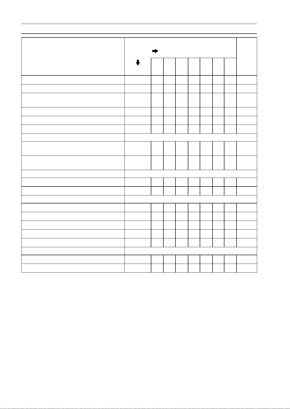
2-4 PERIODIC MAINTENANCE
Periodic Maintenance Chart
FREQUENCY Whichever
comes
first
* ODOMETER READING
×1000km
(× 1 000 mile)
1 6 12 18 24 30 36
INSPECTION Every (0.6) (4) (7.5) (12) (15) (20) (24)
See
Page
Brake hose and pipe damage - inspect year
• • • • • • •
2-31
Brake hose installation condition - inspect year
• • • • • • •
2-31
Brake operation (effectiveness, play, no
drag) - inspect
year
• • • • • • •
2-31
Brake fluid level - inspect 6 months
• • • • • • •
2-32
Brake pad wear - i nspect #
• • • • • •
2-33
Brake light switch operation - inspect
• • • • • • •
2-33
Suspensions
Front forks/rear shock absorber operation
(damping and smooth stroke) - inspect
• • •
2-34
Front forks/rear shock absorber oil leak -
inspect
year
• • •
2-34
Steering System
Steering play - inspect
year
• • • •
2-35
Steering stem bearings - lubricate 2 years
•
2-36
Electrical System
Spark plug condition - inspect
• • •
2-37
Lights and switches operation - inspect year
• • •
2-38
Headlight aiming - inspect year
• • •
2-40
Sidestand switch operation - inspect year
• • •
2-41
Engine stop switch operation - inspect year
• • •
2-42
Others
Chassis parts - lubricate year
• • •
2-43
Bolts and nuts tightness - inspect
• • • •
2-44
#: Service more frequently when operating in severe conditions; dusty,wet, muddy,high speed or
frequent starting/stopping.
*: For higher odometer readings, repeat at the frequency interval established here.
http://mototh.com
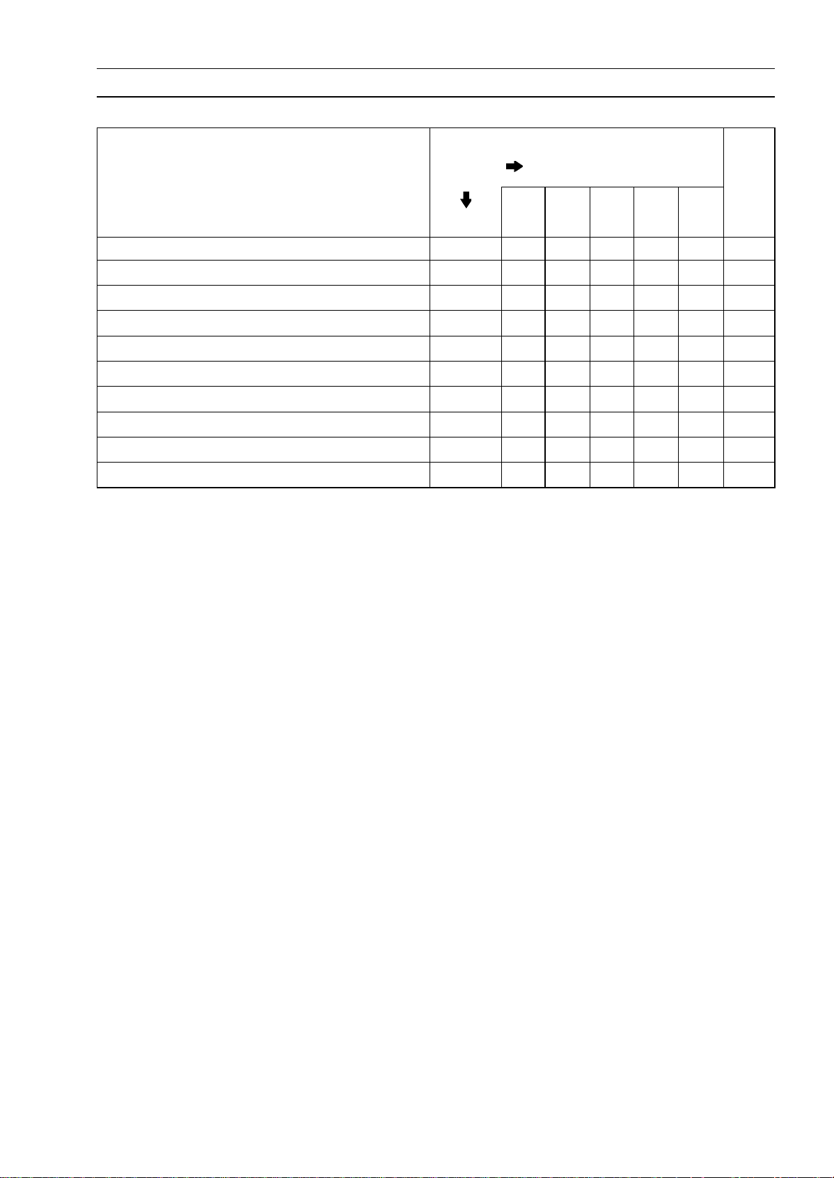
PERIODIC MAINTENANCE 2-5
Periodic Maintenance Chart
Periodic Replacement Parts
FREQUENCY Whichever
comes
first
*ODOMETER READING
× 1 000 km
(× 1 000 mile)
1 12 24 36 48
CHANGE/REPLACE ITEM Every (0.6) (7.5) (15) (24) (30)
See
Page
Air cleaner element # 2 years 2-45
Engine oil # year
• • • • •
2-45
Oil filter year
• • • • •
2-46
Fuel hose 4 years
•
2-46
Coolant 3 years
•
2-47
Radiator hose and O-ring
3 years
•
2-50
Brake hose and pipe 4 years
•
2-51
Brake fluid 2 years
• •
2-51
Rubber parts of master cylinder and caliper 4 years
•
2-53
Spark plug
• • • •
2-56
#: Service more frequently when operating in severe conditions; dusty, wet, muddy, high speed or
frequent starting/stopping.
*: For higher odometer readings, repeat at the frequency i nterval established here.
http://mototh.com
2-6 PERIODIC MAINTENANCE
Torque and Locking Agent
The following tables list the tightening torque for the major fasteners requiring use of a
non-permanent locking agent or liquid gasket.
Letters used in the “Remarks” column mean:
AL: Tighten the two clamp bolts alternately two times to ensure even tightening torque.
EO: Apply engine oil.
L: Apply a non-permanent locking agent to the threads.
Lh: Left-hand threads
MO: Apply molybdenum disulfide oil solution.
R: Replacement Parts
S: Tighten the fasteners following the specified sequence.
Si: Apply silicone grease (ex. PBC grease).
SS: Apply silicone sealant.
Torque
Fastener
N·m kgf·m ft·lb
Remarks
Fuel System
Water Temperature Sensor 12 1.2 106 in·lb
Speed Sensor Bolt 7.8 0.80 69 in·lb L
Fuel Pump Bolts 9.8 1.0 87 in·lb L, S
Oxygen Sensor
44.1 4.50 32.5
Cooling System
Radiator Hose Clamp Screws 2.0 0.20 17 in·lb
Water Pump Impeller Bolt 9.8 1.0 87 in·lb
Water Pump Cover Bolts 9.8 1.0 87 in·lb
Water Pump Drain Bolt 7.0 0.70 62 in·lb
Thermostat Housing Bolts 9.8 1.0 87 in·lb
Water Temperature Sensor 12 1.2 106 in·lb
Engine Top End
Air Suction Valve Cover Bolts 9.8 1.0 87 in·lb
Cylinder Head Cover Bolts 9.8 1.0 87 in·lb
Camshaft Cap Bolts 12 1.2 106 in·lb S
Cylinder Head Bolts (M10 New Bolts)
54 5.5 40
MO, S
Cylinder Head Bolts (M10 Used Bolts) 49 5.0 36 MO, S
Cylinder Bolt (M8) 27.5 2.8 20 MO, S
Cylinder Nut (M10) 49 5.0 36 MO, S
Cylinder Head Bolts (M6) 12 1.2 106 in·lb S
Cylinder Bolts (M6) 12 1.2 106 in·lb S
Throttle Body Holder Bolts 12 1.2 106 in·lb
Rear Camshaft Chain Guide Bolt 20 2.0 15 L
Camshaft Chain Tensioner Mounting Bolts 9.8 1.0 87 in·lb
Camshaft Chain Tensioner Cap Bolt
20 2.0 15
Camshaft Sprocket Bolts 15 1.5 11 L
Spark Plugs 15 1.5 11
Exhaust Pipe Manifold Holder Nuts 17 1.7 12
Muffler Body Mounting Bolt (Front) 20 2.0 15
Muffler Body Mounting Bolt (Rear) 20 2.0 15
Baffle Plate Bolts
5.9 0.60 52 in·lb L
http://mototh.com

PERIODIC MAINTENANCE 2-7
Torque and Locking Agent
Torque
Fastener
N·m kgf·m ft·lb
Remarks
Clutch
Upper Cap on Clutch Cover 3.9 0.40 35 in·lb
Lower Cap on Clutch Cover
– – –
Hand-tighten
Oil Filler Plug – – – Hand-tighten
Clutch Cover Mounting Bolts 9.8 1.0 87 in·lb
Clutch Spring Bolts 9.8 1.0 87 in·lb
Clutch Hub Nut
132 13.5 98 R
Clutch Lever Clamp Bolts 7.8 0.80 69 in·lb S
Oil Pump Chain Guide Bolts 12 1.2 106 in·lb L
Clutch Cable Holder Bolts 9.8 1.0 87 in·lb L
Clutch Cable Clamp Bolt 9.8 1.0 87 in·lb
Engine Lubrication
Engine Oil Drain Bolt 20 2.0 15
Filter Plate Bolt 9.8 1.0 87 in·lb L
Oil Filter 17.2 1.75 13 EO, R
Holder Mounting Bolt 25 2.5 18 L
Oil Pan Bolts 12 1.2 106 in·lb
Oil Pipe Bolts 9.8 1.0 87 in·lb
Oil Pipe Plate Bolt 9.8 1.0 87 in·lb L
Oil Pressure Relief Valve 15 1.5 11 L
Oil Pressure Switch 15 1.5 11 SS
Oil Pump Cover Bolts
9.8 1.0 87 in·lb L
Oil Pump Sprocket Bolt 12 1.2 106 in·lb L, Lh
Oil Passage Plug 20 2.0 15 L
Oil Plate Bolts 9.8 1.0 89 in·lb L
Engine Removal/Installation
Engine Mounting Bracket Bolts 25 2.5 18
Front Engine Mounting Bolts 44 4.5 32
Rear Engine Mounting Nuts 44 4.5 32
Crankshaft/Transmission
Oil Plate Bolts
9.8 1.0 87 in·lb L
Breather Plate Bolts 9.8 1.0 87 in·lb L
Crankcase Bolts (M9, L = 113 mm) 44 4.5 32 MO, S
Crankcase Bolts (M9, L = 83 mm)
44 4.5 32
MO, S
Crankcase Bolts (M8, L = 73 mm) 35 3.6 26 MO, S
Crankcase Bolts (M8, L = 60 mm) 35 3.6 26 MO, S
Crankcase Bolts (M8, L = 110 mm) 27.5 2.8 20 S
Crankcase Bolts (M8, L = 50 mm) 27.5 2.8 20 S
Crankcase Bolts (M6) 19.6 2.0 15 S
Upper Crankcase Bolts
27.5 2.8 20
S
Shift Drum Bearing Holder Screw 4.9 0.50 43 in·lb L
Connecting Rod Big End Nuts see Text ← ← ←
Timing Rotor Bolt 40 4.1 30
http://mototh.com

2-8 PERIODIC MAINTENANCE
Torque and Locking Agent
Torque
Fastener
N·m kgf·m ft·lb
Remarks
Oil Pressure Switch
15 1.5 11
SS
Oil Passage Plug 20 2.0 15 L
Gear Positioning Lever Bolt 12 1.2 106 in·lb L
Shift Shaft Return Spring pin 29 2.9 22 L
Shift Drum Cam Bolt 12 1.2 106 in·lb L
Neutral Switch 15 1.5 11
Transmission Case Bolts
20 2.0 15
Shift Rod Plate Bolt 9.8 1.0 87 in·lb
Neutral Switch Holder Screw 4.9 0.50 43 in·lb L
Shift Shaft Cover Bolts 9.8 1.0 87 in·lb L(seeText)
Shift Shaft Cover Screw 4.9 0.50 43 in·lb L
Wheels/Tires
Front Axle 108 11.0 80
Front Axle Clamp Bolt 34 3.5 25
Rear Axle Nut 108 11.0 80
Final Drive
Engine Sprocket Nut 125 12.7 92 MO
Rear Axle Nut 108 11.0 80
Rear Sprocket Nuts
59 6.0 44
Speed Sensor Bolt 7.8 0.80 69 in·lb L
Speed Sensor Bracket Bolts 9.8 1.0 87 in·lb
Brakes
Bleed Valve 7.8 0.80 69 in·lb
Brake Hose Banjo Bolts 25 2.5 18
Brake Lever Pivot Bolt 1.0 0.10 9in·lb Si
Brake Lever Pivot Bolt Locknut 5.9 0.60 52 in·lb
Brake Pedal Bolt 8.8 0.90 78 in·lb
Front Brake Disc Mounting Bolts 27 2.8 20 L
Front Brake Light Switch Screw 1.0 0.10 9in·lb
Front Brake Reservoir Cap Screws 1.0 0.10 9in·lb
Front Caliper Mounting Bolts
34 3.5 25
Front Master Cylinder Clamp Bolts 8.8 0.90 78 in·lb S
Rear Brake Disc Mounting Bolts 27 2.8 20 L
Rear Caliper Mounting Bolts
25 2.5 18
Rear Master Cylinder Mounting Bolts 25 2.5 18
Rear Master Cylinder Push Rod Locknut 18 1.8 13
Suspension
Front Axle Clamp Bolt 34 3.5 25
Front Fork Bottom Allen Bolts 30 3.1 22 L
Front Fork Clamp Bolts (Lower) 20 2.0 15 AL
Front Fork Clamp Bolts (Upper) 20 2.0 15
Front Fork Top Plugs 25 2.5 18
Rear Shock Absorber Bolt 59 6.0 44
http://mototh.com
Loading...