


ER-5 2003
Kt(masaki
Motorcycle
Motocyclette
Motorrad
Motoclcletta
OWNEM'$ffiANUAI
ffiANUEIDU
BffiMIEB$Ail[E[TUilG
ER.5
| ilt-J
LJilE
MANUA[E
U$O E
MANUTEilZIONE
Motorcycle
ENGLISH
Owner's
Manual
Whenever You
n"i"*l'n""0
ffiA;
tices.
operating
see
instructionsl
iheir
and
sYmbols
the
maintenance
Always
shown
fol-
prac-
OIh,s
"
ticutar
venient
symbol
note
inteiest
oPeration'
NOTE
indicates
more
for
points
efficient
of
and
par-
con-
warning
fnrc
special
which,
could
loss
This
cial
*ii"n,
coutO'result
struction
instructions
if
result
life.
of
caution
instructions
if
of
sYmbol
correctlY
not
in
Personal
CAUTION
symbol
strictlY
not
damage
in
equiPment'
identifies
pt9":1L11"
tl.
followed'
iniury
identifies
or
Procedures
observed'
to
or
or
spe-
de'
PRODUCT
THIS
uincruneo
ionaele
ei
AS
AND
ounLtFlED
I
VEHICLE
A
NOTICE
HAS
usE
FoR
PRUDENT
oPERAToR
ONLY.
BEEN
A
lN
MANNER
MAN-
REA-
AND
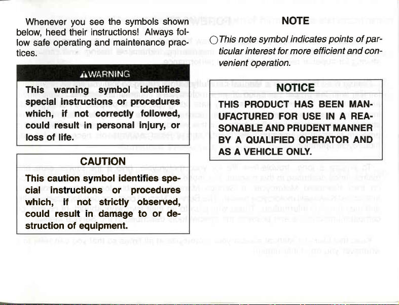
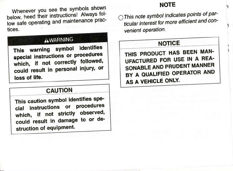
Whenever
below,
low safe operating and
tices.
you
see
heed their instructions!
the symbols shown
Always fol-
maintenance
prac-
note symbol
QThis
interest for more efficient and
ticular
venient operation.
NOTE
indicates
points
of
par-
con-
This warning symbol
special
which, if not correctly
could
loss of life.
This caution symbol
cial
which, if not strictly observed,
could
struction of equipment.
instructions or
result in
instructions
result in damage to or de-
personal
CAUTION
identifies
procedures
followed,
injury
identifies spe-
procedures
or
or
NOTICE
THIS PRODUCT
UFACTURED
SONABLE AND
BY A OUALIFIED OPERATOR
VEHICLE
AS A
HAS BEEN MAN.
FOR
PRUDENT MANNER
ONLY.
USE
IN A REA.
AND
FOREWORD
your
Congratulations
product
the
is
striving
familiar
and
instruction
strongly
progrlm
motorcycle
maintenance described
on
authorized
and
competent
whenever
for superior
please
To ensure a
read this
with the
limitations.
recommends
to attain awareness
their Kawasaki
maintenance
Keep this Owner's
you
on
Kawasaki's
of
reliability,
Owner's
proper
manual offers
This
the techniques
in all
operation.
Kawasaki
mechanics and
that all
long, trouble-free
in this
Motorcycle, a
motorcycle dealer.
information. Those
Manual
information.
need
purchase
Manual carefully
operation
possess
aboard
of a new
advanced
safety and
of
many safe
and skills
operators
mental and
of the
life for
manual.
Service
the
your
Kawasaki
engineering,
performance.
your
motorcycle's controls,
riding tips, but
required to
of this
your
For those
Manual
The
Service
plan
who
special
motorcycle
exhaustive
riding
before
ride a motorcycle safely.
vehicle enroll
physical
motorcycle,
who would
is available
Manual contains
their own
to do
tools described
at all
motorcycle. Your new
testing, and
you
that
so
purpose
its
in a motorcycle
requirements
give
like more detailed
work should,
in the Service
times so that
will be thoroughly
features, capabilities,
its
necessary
it the
purchase
for
detailed
is not
rider
proper
disassembly
of course,
you
can
motorcycle
continuous
provide
to
Kawasaki
training
for safe
and
care
information
lrom any
be
Manual.
refer to it
manual
This
motorcycle
the
with
reserved.
rights
All
permission.
publication
This
ni"V O"
tn"i"
manual.
niiprooucts
should
when
includes
differences
minor
subject
are
considered
be
No
it is
part
the
to
sold.
of this
change
permanent
a
publication
information
latest
between
without
the
part
may
available
actual
prior
notice
motorcycle
the
of
reproduced
be
at
product
and
obligation.
or
without
of
time
the
illustrations
remain
should
and
prior
our
printing' However'
and
written
text
in this
@
2003
Kawasaki
Heavy
KAWASAKI
Consumer
lndustries'
Products
HEAVY
&
Ltd.
INDUSTRIES'
Machinery
LTD.
Company
Jan.
2004.
(2). (M)
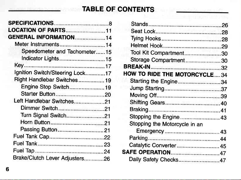
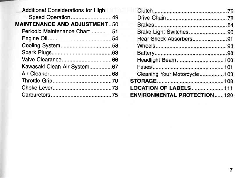
TABLE
OF
CONTENTS
spEctFtcATtoNS....................................
LOCATTON
GENERAL |NFORMAT|ON....................
Meter
Key...............
gnition
I
Right
Left
Fuef
FuelTank.....
FuelTap.......
Brake/Clutch
6
OF PARTS..........................
I nstruments..............
Speedometer
lndicator
Switch/Steering
Handlebar
Engine
Starter
Handlebar
Dimmer
Turn
Signal
Horn
Button.
Passing
Tank
and Tachometer......
Lights..............................
Switches.................
Stop
Switch.......................
Button...........
Switches..
Switch ..........
Switch...........
Button
..........
Cap..............
Lever
Adjusters.............26
................
.................17
Lock.............
.....................
..................21
....................21
..............21
.............21
....................
......................22
.................29
.................24
1 1
1 4
1 4
1
5
1
5
1 7
1
9
1
9
ZO
21
8
Additional
Speed Operation ...........................
MAINTENANCE AND ADJUSTMENT..
Periodic Maintenance
Engine
Cooling System..................................
Spark Plugs.. .................63
Valve
Kawasaki
Air Cleaner...
Throttle
Choke Lever ..................73
Carburetors..
Considerations
Oi1..........................................
C|earance.................................
Clean Air System...............67
Grip....................................... 70
for
High
49
50
Chart..............
.................68
.................75
51
54
58
66
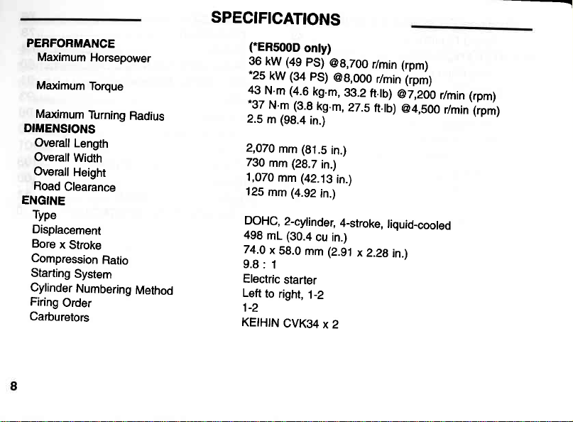
SPECIFICATIONS
PERFORMANCE
Maximum
Maximum
Maximum
DIMENSIONS
Overall
Overall
Overall
Road
ENGINE
Type
Displacement
Bore
Compression
Starting
Cylinder
Firing
Carburetors
Horsepower
Torque
Turning
Length
Width
Height
Clearance
x
Stroke
Ratio
System
Numbering
Order
Radius
Method
(-ER500D
39
(49
kW
(34
kW
-?5
49
N m (4.6
(3.8
m
_31N
2.5 m (98.4
2,070
mm (81.5
730
mm (28.7
1,070
mm
125
DOHC,
498
74.0
9.8:
Electric
Left
1-2
KEfHfN
(4.92
mm
2-cylinder,
(30.4
mL
x
58.0
1
starter
to
right,
CVK}4
onty)
PS)
@8,700
ps)
@8,ooo
gO.2
kg.m,
kg.m,
in.)
in.)
in.)
(42j9
in.)
in.)
4-stroke,
cu in.)
mm (2.91
1-2
x2
r/min (rpm)
r/min
ft.tb)
liquid_cooled
x
2.28
@7,200
in.l
27.sft.tb)
(ipm)
r/min (rpm)
@4,soo
r/min'(ipm)
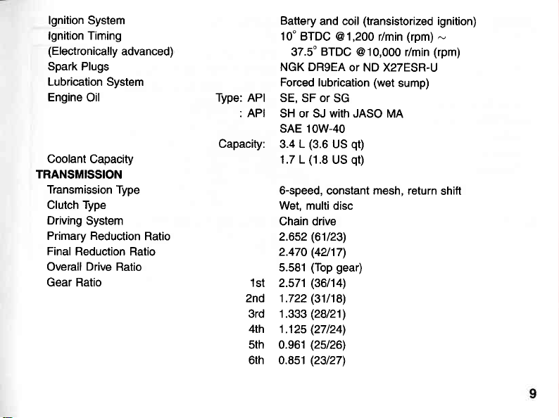
lgnition System
lgnition Timing
(Electronically
Spark Plugs
Lubrication System
Engine
Oil
Coolant Capacity
TRANSMISSION
Transmission Type
Clutch Type
Driving
System
Primary Reduction
Final
Reduction Ratio
Drive
Overall
Gear Ratio
Ratio
advanced)
Ratio
API
Type:
API
Capacity:
1st
2nd 1.722
3rd 1.333
4th
5th 0.961
6rh 0.8s1
Battery
and coil
10'BTDC
37.5" BTDC
NGK DR9EA
Forced
lubrication
SE.
or
SF
SH or SJ with JASO
(transistorized
@1,200 r/min
(rpm)
@10,OOO r/min
or ND X27ESR-U
(wet
sump)
SG
MA
ignition)
(rpm)
SAE 1OW-40
(3.6
(1.8
US
US
qQ
qt)
3.4 L
1.7 L
6-speed, constant mesh, return
Wet, multi disc
Chain drive
(61t23)
2.652
(42t17)
2.470
(Top
5.581
2.571
gear)
(36|t4l
(311'18)
(28121)
(27/24)
1j25
(25126)
(23127)
-
shift
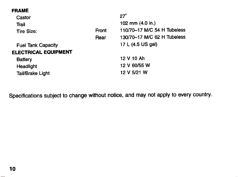
FRAME
Castor
Trail
Size:
Tire
Tank Capacity
Fuel
ELECTRICAL
Battery
Headlight
TaiUBrake
EQUIPMENT
Light
Fronl
Rear
27'
(4.0
mm
102
(4.5
M/C
M/C 62
US
fOnAST
13OnUl7
17 L
12V10Ah
12 V 60/55
12V 5121W
in.)
gal)
W
Tubeless
H
54
H Tubeless
Specifications
subject
10
to change
without
notice, and
may not apply
to every
country.
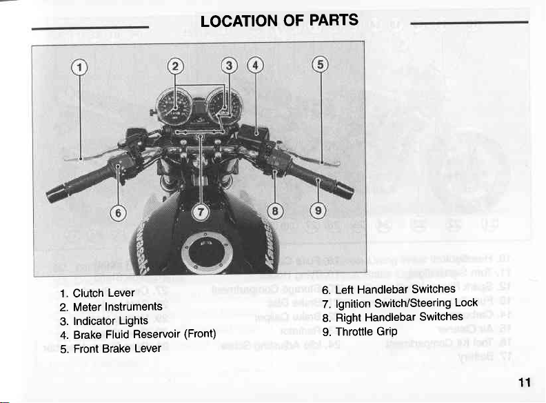
LOCATION
OF
PARTS
1. Clutch
Meter
2.
Indicator
3.
Brake
4.
Front
5.
Lever
Instruments
Lights
Reservoir
Fluid
Lever
Brake
(Front)
Left Handlebar
6.
7.
8.
9.
Switch/Steering
lgnition
Handlebar
Right
Throttle
Grip
Switches
Lock
Switches
11
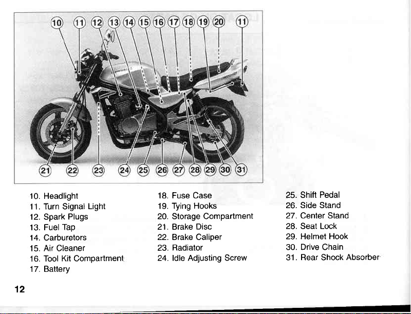
10. Headlight
11. Turn Signal
12. Spark
13. Fuel
14.
Carburetors
15. Air Cleaner
16. Tool
17. Battery
12
Light
Plugs
Tap
Kit Compartmenl
18. Fuse Case
19. Tying
20. Storage Compartment
21. Brake
22. Brake Caliper
23.
24. ldle Adjusting Screw
Hooks
Disc
Radiator
Seat
Pedal
Lock
25. Shift
26. Side Stand
27. Center Stand
28.
29. Helmet Hook
30. Drive Chain
31. Rear Shock
Absorber
6D
T
I
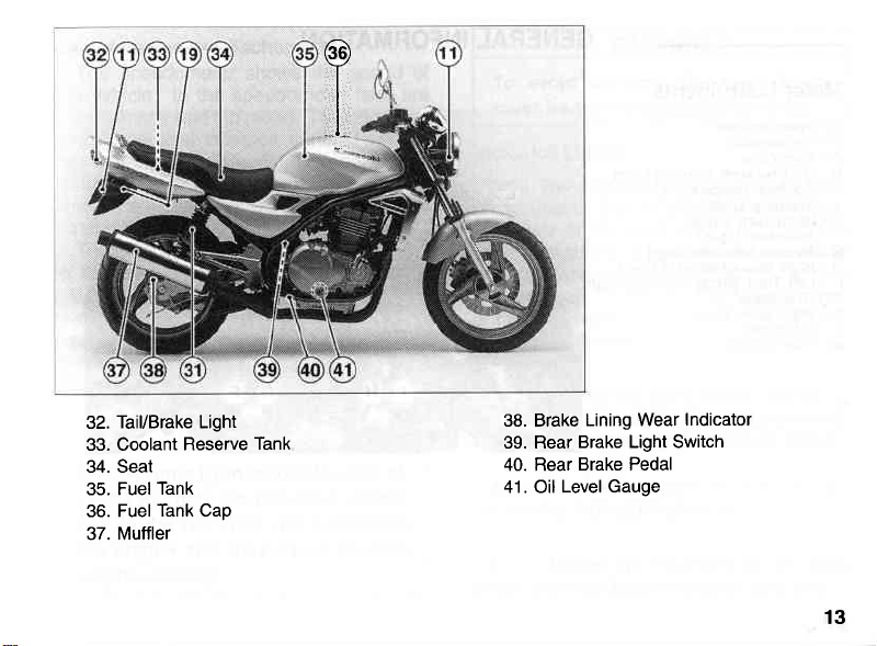
Tail/Brake Light
32.
33. Coolant
34. Seat
35. Fuel
36. Fuel
37.
Tank
Tank Cap
Muffler
Reserve
Tank
38. Brake
39. Rear
40. Rear
Level Gauge
4'l . Oil
Lining Wear
Brake Light Switch
Brake Pedal
Indicator
13
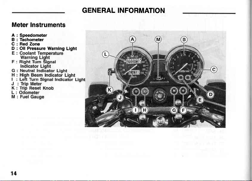
Meter Instruments
A: Speedometer
B : Tachometer
C : Red Zone
D :
Oil Pressure Warning
14
GENERAL INFORMATION
Light
Speedometer
The speedometer shows
vehicle. In
the
odometer and trip
the
shows
has
been
distance
zero. The trip meter can be reset to zero by
turning
The
tachometer shows
in the revolutions
the right side of the tachometer
On
portion
(rpm)
in the red zone is above maximum
recommended engine speed and
above the range for
Engine r/min
lowed to enter the red zone; operation in the red zone
the engine and
engine damage.
and Tachometer
the speed of
the
speedometer
meter. The odometer
the total distance that the
ridden. The trip meter shows the
traveled since it was last reset to
the reset knob
the
called
counterclockwise.
the
per
minute
"red
zone." Engine
good performance.
CAUTION
(rpm)
should not be al-
will
may
cause
face are
vehicle
speed
engine
(r/min,
rpm).
face is
is
overstress
serious
r/min
also
CAUTION
To
must be
Indicator Lights
tzl
on whenever the oil
ously low or the ignition key
position
goes
a
high enough. Refer to the Maintenance
Adjustment chapter for more detailed
and
engine
QO
turned to left or right, the corresponding
turn
signal
N: When the transmission
the neutral indicator
=D
beam, the
damage, the reset knob
avoid
turned
; T1'19 oil
with the engine not running, and
off when the engine oil
oil information.
: When the turn signal switch
indicator
; When the
high
countercloclanrise.
pressure
beam
warning light
pressure
is in
pressure
light flashes
is in neutral,
light is lit.
headlight is
indicator light is lit.
goes
is
danger-
the ON
on and off.
high
on
15
is
is
=E:
The
goes
to
starts running
functions
goes
rises
motorcycle
stop the
in
down.
Fuel
The
in
16
coolant
when
on
"ON"and
the reserve
Do
ning
on, Prolonged
result
heating.
the fuel
goes
properly.
on whenever
to 120'C
is in
engine
not let
Gauge
when
in
fuel
the
severe
gauge
tank.
temperature
the
ignition
off soon
to
ensure
The warning
the
coolant temperature
(248"F)
and
tank
the
or higher
operation.
check the
after the
engine
engine
shows
When
continue
warning
operation
damage
the amount
the needle
warning
key is
after the
that its
light
when
lf it
stays
coolant
engine
light
from
over-
light
turned
engine
circuit
also
the
on,
level
cools
run-
goes
will
of fuel
comes
near
the E(empty)
earliest
opportunity.
position,
Key
This
which
ing lock,
tank
Kawasaki
make
need,
motorcycle
is
cap.
Blank
any
using
used for
seat lock,
the ignition
keys
are
dealers.
additional
your
original key
has
a combination
helmet
hook
available
your
Ask
spare keys
key,
switch/steer-
and fuel
your
at
dealer
you
to
may
as a master.
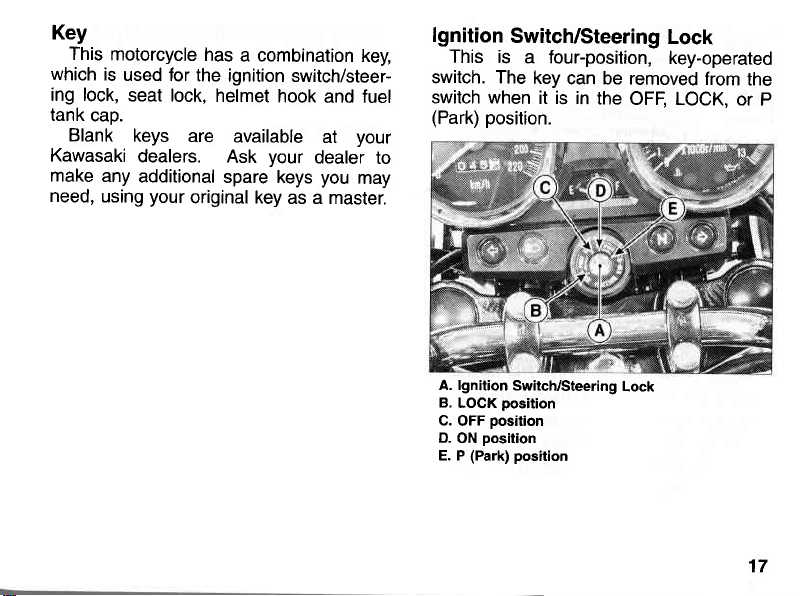
lgnition
This is
Switch/Steering
a four-position,
switch. The
switch when
(Park)
position.
key
can be removed
it is in
the
Lock
key-operated
from
OFF, LOCK.
the
or P
A. lgnition
B.
LOCK
position
C.
OFF
position
D.
ON
(Park)
E. P
Switch/Steering
position
position
Lock
17
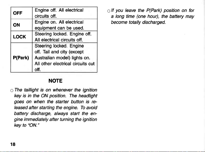
OFF
ON
LOCK
P(Park)
Engine off.
circuits otf.
Engine on. All electrical
equioment can be used.
Steering
All electrical circuits off.
Steering
otf. Tail and city
Australian model) lights on.
All
other electrical circuits cut
All
electrical
locked. Engine
locked.
Engine
(except
off.
NOTE
taiilight is on whenever the ignition
sThe
key is in
goes
on
the ON
when
position.
The headlight
the starter bufton is released after starting the engine. To
battery discharge,
gine
immediately
"ON."
key to
always start
after turning the ignition
18
otf.
avoid
the
en-
g
you
lf
leave the P(Park)
a long time
(one
hour),
become totally discharged.
position
on for
the baftery may
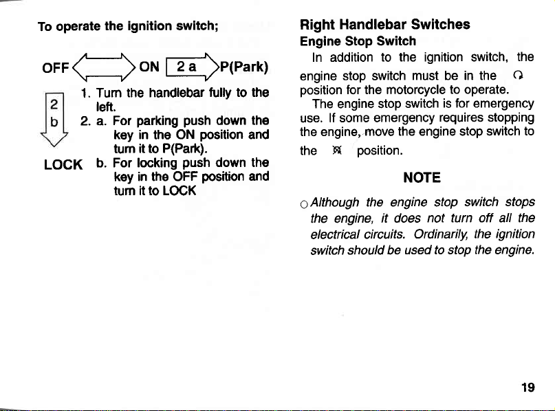
operate
To
oFF<
LOCK
the ignition switch;
/--\
\-----------ll
1. Tum
)oNl2a )P(Park)
the handlebar fully
left.
parking push
For
2. a.
key in
the
it to P(Park).
tum
For locking
b.
in the OFF
key
tum it to LOCK
--'------y
ON
position
push
position
to the
down the
and
down the
and
Handlebar Switches
Right
Engine Stop Switch
In addition
engine
position
The engine stop
lf some emergency
use.
the engine,
X
the
to the ignition switch,
stop switch
for the motorcycle
switch
move the engine stop switch
position.
NOTE
6Although
the engine,
electrical
switch
the engine stop switch
it does
circuits.
should be
used to stop the engine.
must
be
in the
to operate.
is for emergency
requires stopping
not turn off all the
Ordinarily, the
ignition
the
O
to
stops
19
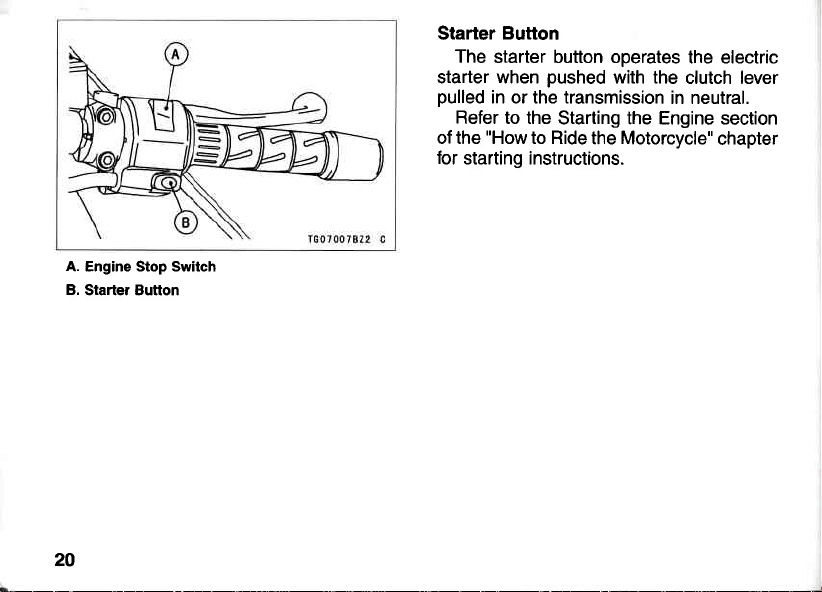
A. Engine Stop Switch
B.
Starter Button
20
Starter
starter when
pulled
of the
for
Button
The
starter button operates
pushed
in or the transmission
Refer to the
"How
Starting the Engine section
to Ride
starting instructions.
with the
clutch lever
in neutral.
the electric
the Motorcycle"
chapter
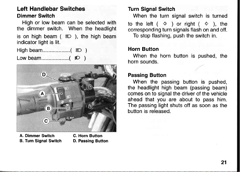
Handlebar
Left
Switches
Dimmer Switch
High
low
or
beam can be selected with
the dimmer switch. When the headlight
(
is on high beam
=D
the high
),
beam
indicator light is lit.
Highbeam.......... ..(
Low
beam...................(
s
D
)
)
Turn SignalSwitch
When the turn
(
to the left
corresponding
To
stop
tr
turn
flashing,
Horn Button
When
horn
sounds.
the
horn
signal switch
(
right
or
)
flash
signals
push
the switch in.
button is
pushed,
is
turned
O
the
),
on and off.
the
A.
Dimmer Switch
B. Turn
Signal Switch D. Passing Button
Horn Button
C.
Passing
the
Button
When
the
headlight high
passing
beam
button is
(passing
comes on to signal the driver
ahead that
passing
The
you
are about to
light shuts off as
button is released.
pushed,
beam)
the vehicle
of
pass
soon as the
him.
21
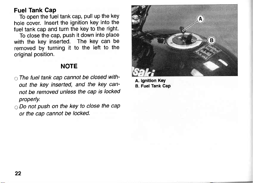
Tank Cap
Fuel
To open
cover.
hole
luel tank
To close
with the
removed
original
fuel tank
c:The
out the
be
not
properly.
gDo
not
the cap
or
22
fuel tank
the
cap and
the
key
by turning
Insert
turn
cap,
inserted.
the ignition
push
it to
position.
NOTE
cap cannot
inserted,
key
removed unless
push
the
on
cannot
be
pull
cap,
up
key into
the
it
down
into
to the
key
The key
the left
closed
be
the
and
the cap
key to close
locked.
key
the
the
right.
place
can be
to the
with-
key can-
locked
is
the cap
A. lgnition
B. Fuel Tank
Key
Cap
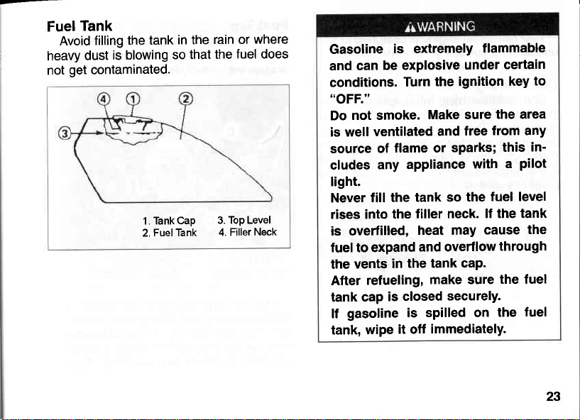
Tank
Fuel
Avoid
heavy
get
not
filling the
dust
tank
is blowing
contaminated.
'1.
Tank
Fuel Tank
2.
in the
so that
Cap
rain or
fuel does
the
3. Top Level
4. Filler
where
Neck
Gasoline
and
conditions.
"oFF."
Do
is well
source
cludes
is extremelY
be exPlosive
can
Turn
not smoke.
ventilated
flame or
of
any appliance
light.
fill the
Never
rises into
the
is overfilled,
fuel to expand
the tank caP.
in
vents
the
refueling,
After
closed
is
cap
tank
gasoline
lf
tank,
wipe
is
it off
flammable
under
the ignition
Make sure
free
and
sParks;
with
tank so
filler neck.
heat may
the
lf the
cause
and overflow
make sure
securelY.
spilled on
immediatelY.
certain
to
key
the area
from any
in'
this
a
Pilot
fuel level
tank
the
through
the fuel
fuel
the
23
Requirement:
Fuel
Kawasaki engine
Your
unleaded
Octane
The octane
measure of
"knocking."
describe
Research Octane
use a
to,
lt
o
a different
octane
gasoline.
Rating
its resistance
The term commonly
gasoline's
a
gasoline
higher than,
or
"knocking"
rating.
rating of a
with an octane
or
brand
is
designed
to detonation
octane
Number
RON 91.
NOTE
"pinging"
gasoline
of
gasoline
used
rating
(RON).
rating equal
occurs,
or higher
to use
is a
or
to
is the
Always
use
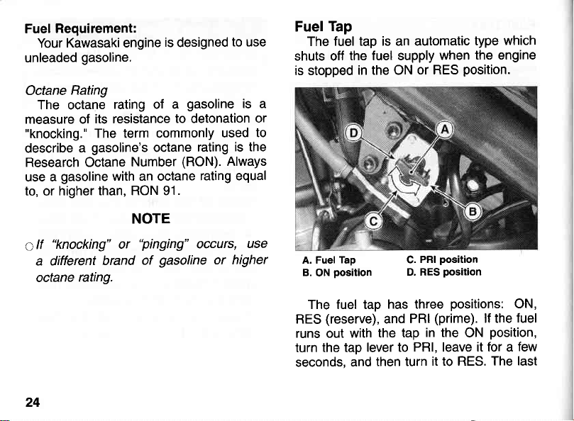
Tap
Fuel
fuel tap is an automatic
The
shuts off
is stopped
A. Fuel
B.
the fuel supply
in the ON
Tap C.
position
ON
or RES
PRI
D. RES
when
position.
position
position
which
type
the engine
24
The fuel tap
(reserve),
RES
runs out with
the tap
turn
seconds.
and
has three
and
the tap
lever to
then turn
positions:
(prime).
PRI
in the
PRl, leave it for a
it to RES. The
ON
lf the
position,
ON,
fuel
few
last
(0.8
L
3.0
turning the
The PRI
and
control
running out of
after
draining
oSince
RES, refuel at the earliest opportunity.
Make
o
turned to
the fuel tank.
start a cold engine
aTo
has
cle
turn the tap lever to PRl,
moment, and return it to ON.
gal)
US
fuel
position
is
useful
the tank.
riding distance
certain
ON
been stored
fuel
of
lever to RES.
tap
bypass the automatic
for
gas,
NOTE
that the fuel tap
(Not
RES) after filling up
be used by
can
priming
is limited when on
for a long time,
the engine
for completely
or
lever is
after the
motorcy-
leave it for a
first
Practice operating the fuel tap with
motorcycle
the
an accident
operate
without taking
road.
Be careful not to touch the
engine
Do not leave the fuel tap
PRI
parking
may become
spill
fire hazard, if the
while operating the fuel tap.
(prime) position
the motorcycle. The engine
onto the
stopped.
you
should be
the fuel tap while riding
your
while riding
flooded
ground
vehicle falls
prevent
To
able
eyes off the
hot
in the
fuel may
or
and create a
over.
to
or
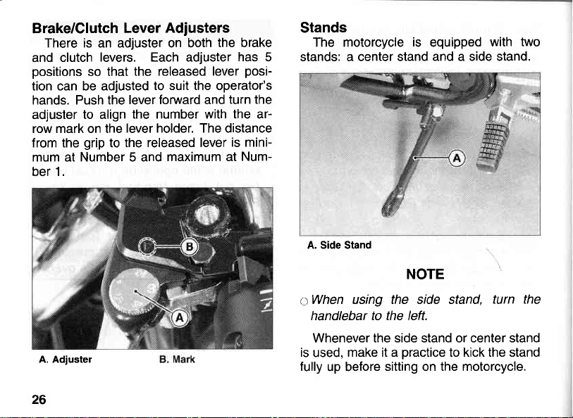
Adjusters
Brake/Clutch
There is an adjuster on both
clutch
and
positions
tion can be adjusted
hands. Push the
adjuster
row mark on the
from the
mum at Number 5 and
ber 1.
Lever
levers. Each adjuster
so that the
to align
grip
to the
released
to suit the operator's
lever forward and
the number with the ar-
lever holder. The distance
released lever
maximum at
the brake
has
posi-
lever
turn the
is mini-
Num-
Stands
The motorcycle
stands: a center stand
5
A. Side Stand
is
equipped
and a side stand.
NOTE
with two
A. Adiuster
26
c:When
is
fully
using the side stand,
handlebar to the left.
Whenever the side stand or center stand
make it a
used,
up before
practice
sitting on the motorcycle.
to kick the stand
turn the
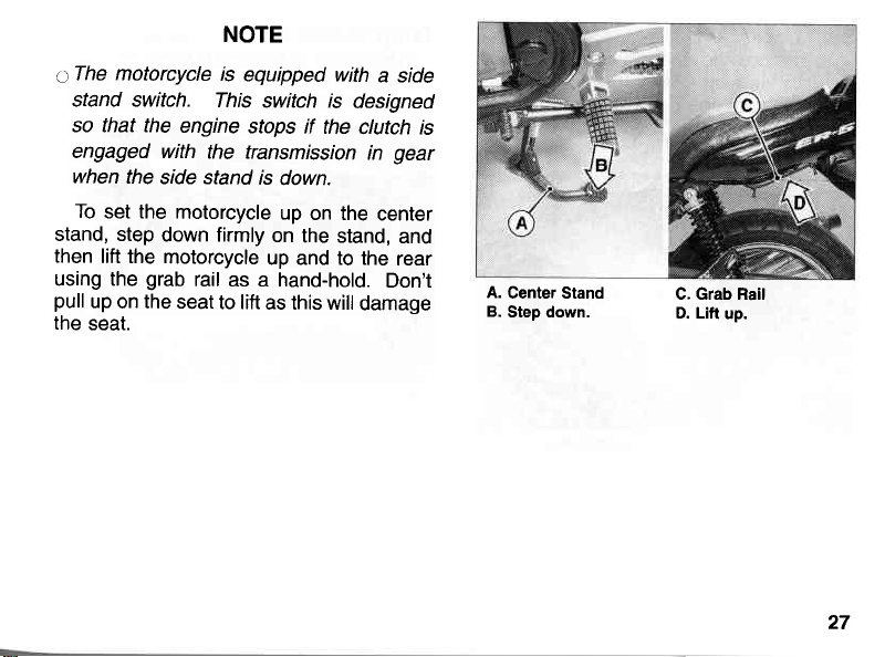
NOTE
motorcycle
aThe
stand switch.
so that the
engaged with
when
the
To
set the
stand, step
then
lift the
using the
pull
the
grab
up
on the seat
seat.
is
equipped with
This
engine
stops if
the transmission
side stand
motorcycle
down firmly
motorcycle
rail
as a hand-hold.
to lift
switch is
is
down.
up
on
designed
the
clutch is
on the
the stand,
up and to the
as this will
damage
a side
gear
in
center
and
rear
Don't
A.
Center Stand
B.
Step down.
C. Grab Rail
D. Lift
up.
27
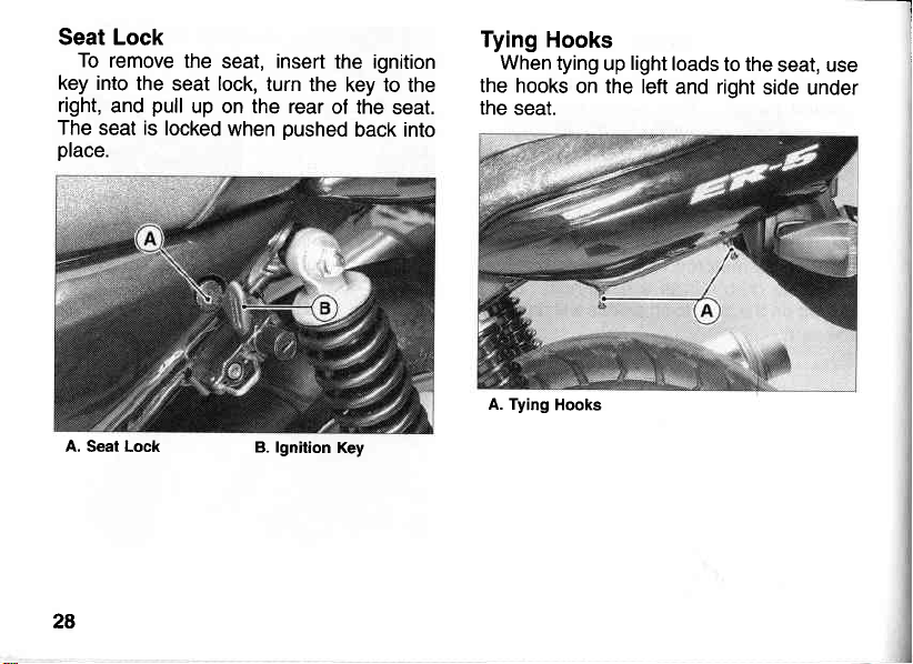
Seat Lock
To
remove
key into
right,
the seat lock,
and
The seat is
place.
A.
Seat Lock
28
the
seat,
pull
up on the rear
locked
when
insert
turn
the key to
pushed
B. lgnition
the ignition
the
of the
seat.
back into
Key
Tying
the hooks
the seat.
When
A. Tying
Hooks
tying
Hooks
light
up
on the left
loads
to the
and right
seat, use
side
under
l
l
I
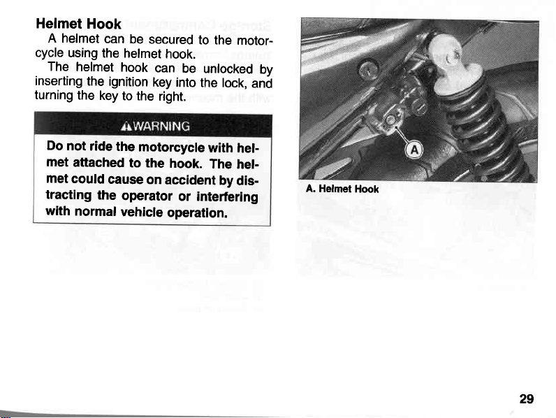
Helmet
A helmet
cycle
using
The
helmet
inserting
turning
Do
met
met
not
the
attached
could
tracting
with
normal
Hook
can
be
the helmet
hook
the
ignition
key
to the
ride
the
to the
cause
the
operator
vehicle
secured
to the
hook.
can
be
key
into
the lock,
right.
motorcycle
hook.
on
accident
or interfering
operation.
motor-
unlocked
and
with
hel-
The
heh
by
dis-
by
A. Helmet
Hook
29
 Loading...