


ER-6n
Free
Download
|
Whenever you see the symbols |
|
NOTE |
|
shown below, heed their instructions! |
|
This note symbol indicates points of |
||
Always follow safe operating and main- |
|
particular interest for more efficient |
||
tenance practices. |
|
and convenient operation. |
||
|
|
|
.orgNOTICE |
|
|
WARNING |
|||
|
|
|
||
|
This warning symbol identifies |
|||
|
|
THIS PRODUCT HAS BEEN |
|
|
|
special instructions or proce- |
|
|
|
|
|
MANUFACTURED FOR USE IN A |
|
|
|
dures which, if not correctly fol- |
|
|
|
|
|
REASONABLE AND PRUDENT |
|
|
|
lowed, could result in personal |
|
|
|
|
|
MANNER BY A QUALIFIED OP- |
|
|
|
injury, or loss of life. |
|
|
|
|
|
ERATOR AND AS A VEHICLE |
|
|
|
|
|
|
|
|
|
|||
|
|
|
ONLY. |
|
|
CAUTION |
|
|
|
|
|
|
|
|
|
This caution symbol identifies |
|
|
|
|
special instructions or proce- |
|
|
|
|
dures which, if not.strictlyClassicCyclesob- |
|||
|
served, could result in damage |
|
|
|
|
to or destruction of equipment. |
|
|
|
|
www |
|
|
|
|
|
|
|
|
FOREWORD
Congratulations on your purchase of a new Kawasaki motorcycle. Your new motorcycle is the product of Kawasaki s advanced engineering, exhaustive testing, and continuous striving for superior reliability, safety and performance.
Please read this OwnerFrees Manual carefully before riding so that you will be thoroughly familiar with the p op r operation of your motorcycle s controls, its features, capabilities, and limitations. This manual offers many safe riding tips, but its
and physical requirements necessary for safe motorcycle operation.
purpose is not to provide instruction in all the techniques and skills required to ride a motorcycle safely. Kawasaki stronglyDownloadrecommends that all operators of this vehicle enroll in a motorcycle rider training pr gram to attain awareness of the mental
To ensure a long, trouble-free life for your motorcycle, give it the proper care and maintenance described in this manual. For those who would like more detailed information on their Kawasaki Motorcycle, a Service M nual is available for purchase from any authorized Kawasaki motorcycle dealer. The Service Manual contains detailed disassembly and maintenance information. Those who plan to do their own work should, of course, be competent mechanics and possess the special tools described in the Service Manual.
Keep this Owner s Manual aboard your motorcycle at all times so that you can refer to it whenever you need information.

TABLE OF CONTENTS
SPECIFICATIONS |
|
|
8 |
|
.org |
|
|
|
Brake/Clutch Lever Adjusters........... |
||||
LOCATION OF PARTS ....................... |
|
12 |
Fuel Tank Cap.................................. |
|
||
GENERAL INFORMATION................. |
|
15 |
Fuel Tank .. |
|
............................... |
|
Meter Instruments |
|
ClassicCycles |
|
|||
|
|
15 |
Fuel Requirement: ........................ |
|||
Tachometer Gauge: ...................... |
|
16 |
Stand................................................ |
|
|
|
LCD (Speedometer, Clock, |
|
|
Seat Lo k ......................................... |
|
|
|
Odometer, Trip Meters, Warning |
|
Helmet Holding Cable ...................... |
||||
Symbols): .................................. |
|
|
17 |
Tool Kit/U-Shaped Lock |
||
Warning/Indicator Lights: .............. |
|
23 |
Compartment................................ |
|
||
Key................................................... |
|
|
27 |
Rear View Mirror .............................. |
||
Ignition Switch/Steering Lock........... |
|
27 |
Tying Hooks ..................................... |
|
||
Right Handlebar Switches................ |
|
29 |
BREAK-IN........................................... |
|
|
|
Engine Stop Switch: ..................... |
|
29 |
HOW TO RIDE THE MOTORCYCLE . |
|||
Starter Button: ................... |
|
..... |
30 |
Starting the Engine .......................... |
||
Left Handlebar Switches ....... |
..... |
30 |
Jump Starting................................... |
|
||
Dimmer Switch: ............................ |
|
|
30 |
Moving Off........................................ |
|
|
Turn Signal Switch:....................... |
|
31 |
Shifting Gears .................................. |
|
||
Horn Button: ................................. |
www |
|
31 |
Braking............................................. |
|
|
Passing Button: ............................ |
|
31 |
Stopping the Engine......................... |
|||
Hazard Switch: ............................. |
|
|
31 |
|
|
|
32
33
34
35
36
37
39
40
42
43
44
46
46
48
50
51
52
54
Stopping the Motorcycle in an |
|
|
Engine Vacuum Synchronization ..... |
90 |
Emergency ................................... |
|
54 |
Idle Speed........................................ |
91 |
Parking............................................. |
|
55 |
Clutch............................................... |
92 |
Catalytic Converter........................... |
|
56 |
Drive Chain ...................................... |
94 |
SAFE OPERATION............................. |
|
58 |
Brakes.............................................. |
102 |
Daily Safety Checks......................... |
|
58 |
Brake Light Switches........................ |
106 |
Additional Considerations for High |
|
Front Fork......................................... |
108 |
|
Speed OperationFree.......................... |
60 |
Rear Shock Absorbers..................... |
109 |
|
MAINTENANCE AND ADJUSTMENT |
62 |
Wheels ............................................. |
111 |
|
Periodic Maintenance Chart |
Download |
117 |
||
|
63 |
Battery.............................................. |
||
Engine Oil ........................................ |
|
72 |
Headlight Beam................................ |
122 |
Cooling System................................ |
|
78 |
Rear Turn Signal Light ..................... |
124 |
Spark Plugs...................................... |
|
83 |
Fuses ............................................... |
124 |
Kawasaki Clean Air System............. |
|
85 |
Cleaning Your Motorcycle ................ |
126 |
Valve Clearance............................... |
|
86 |
STORAGE........................................... |
131 |
Air Cleaner ....................................... |
|
86 |
ENVIRONMENTAL PROTECTION..... |
134 |
Throttle Control System ................... |
|
88 |
LOCATION OF LABELS..................... |
135 |

8 SPECIFICATIONS
SPECIFICATIONS
PERFORMANCE |
|
53 kW (72 PS) @8 500 r/min.org(rpm) |
Maximum Horsepower |
||
|
.ClassicCycles |
|
|
(MY) |
46 kW (62.5 PS) @7 000 r/min (rpm) |
Maximum Torque |
|
66 N·m (6.7 kgf·m, 48.7 ft·lb) @7 000 r/min (rpm) |
|
(MY) |
63.2 N·m (6.4 kgf·m, 46.6 ft·lb) @6 500 r/min (rpm) |
Minimum Turning Radius |
2.7 m (106.3 in.) |
|
DIMENSIONS |
|
|
Overall Length |
|
2 100 mm (82.68 in.) |
Overall Width |
|
760 mm (29.92 in.) |
Overall Height |
www |
1 095 mm (43.11 in.) |
ENGINE |
1 405 mm (55.31 in.) |
|
Wheelbase |
|
|
Road Clearance |
|
140 mm (5.51 in.) |
Dry Weight |
|
174 kg (384 lb) |
Type |
|
DOHC, 4-valve, 2-cylinder, 4-stroke, liquid-cooled |

|
|
|
SPECIFICATIONS 9 |
Displacement |
|
|
649 cm3 (39.6 cu in.) |
Bore x Stroke |
|
|
83 x 60 mm (3.27 x 2.36 in.) |
Compression Ratio |
|
11.3 : 1 |
|
Starting System |
Free |
Electric starter |
|
|
Left to right, 1-2 |
||
Cylinder Numbering Method |
|||
Firing Order |
|
|
1-2 |
Carburetion System |
|
Fi (Fuel Injection) |
|
Engine Oil |
|
TypeDownload: API SE, SF or SG |
|
Ignition System |
|
|
Battery and coil (transistorized ignition) |
Ignition Timing |
|
|
10° BTDC @1 300 r/min (rpm) |
(Electronically advanced) |
35° BTDC @4 800 r/min (rpm) |
||
Spark Plugs |
|
|
NGK CR9EIA-9 |
Lubrication System |
|
Forced lubric tion (semi-dry sump) |
|
|
|
|
API SH, SJ or SL with JASO MA |
|
|
|
SAE 10W-40 |
|
|
Capacity : |
2.4 L (2.5 US qt) |
Coolant Capacity |
|
|
1.2 L (1.3 US qt) |
10 SPECIFICATIONS |
|
|
|
|
|
TRANSMISSION |
|
|
|
|
|
Transmission Type |
|
6-speed, return shift |
.org |
||
Clutch Type |
|
|
Wet, multi disc |
||
|
|
|
|||
Driving System |
|
|
Chain drive |
|
|
Primary Reduction Ratio |
6th.ClassicCycles0.852 (23/27) |
||||
|
2.095 |
(88/42) |
|
||
Final Reduction Ratio |
|
3.067 |
(46/15) |
|
|
Overall Drive Ratio |
|
5.473 |
(Top gear) |
|
|
Gear Ratio |
|
1st |
2.438 |
(39/16) |
|
|
|
2nd |
1.714 |
(36/21) |
|
|
|
3rd |
1.333 |
(32/24) |
|
|
|
4th |
1.111 (30/27) |
|
|
|
|
5th |
0.966 |
(28/29) |
|
FRAME |
www |
|
|
|
|
|
|
|
|
|
|
Castor |
|
|
24.5° |
|
|
Trail |
|
|
102 mm (4.0 in.) |
|
|
Tire Size: |
|
Front |
120/70ZR17 M/C (58 W) Tubeless |
||
|
|
|
|
SPECIFICATIONS 11 |
|
|
Rear |
160/60ZR17 M/C (69 W) Tubeless |
|
Rim Size: |
|
Front |
17 |
× 3.50 |
|
|
Rear |
17 |
× 4.50 |
Fuel Tank Capacity |
|
15.5 L (4.1 US gal) |
||
|
Free |
|
|
|
ELECTRICAL EQUIPMENT |
|
|
|
|
Battery |
|
|
12 |
V 10 Ah |
Headlight |
|
|
12 V 55 W/55 W (Hi/Lo) |
|
Tail/Brake Light |
|
Download |
||
|
|
12 |
V 5/21 W |
|
(MY): Malaysian model
Specifications subject to change without otice, and may not apply to every country.
12 LOCATION OF PARTS
LOCATION OF PARTS
|
|
|
|
|
|
|
|
|
.org |
|
|
.ClassicCycles |
||
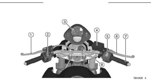
1. |
Clutch Lever |
www |
5. |
Right Handlebar Switches |
2. |
Left Handlebar S itches |
6. |
Front Brake Lever |
|
3. |
Meter Instruments |
7. Throttle Grip |
||
4. |
Brake Fluid Reservoir (Front) |
8. |
Ignition Switch/Steering Lock |
|

LOCATION OF PARTS 13
|
Free |
|
|
|
|
|
|
Download |
|
|
|
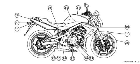
9. |
Wheel |
16. |
Seat |
22. |
Brake Disc |
10. |
Headlight |
17. |
Tool Kit/Storage |
23. |
Brake Caliper |
11. |
Turn Signal Light |
18. |
Compartments |
24. |
Shift Pedal |
12. |
Spark Plugs |
Helmet Holding Cable |
25. |
Side Stand |
|
13. |
Air Cleaner |
19. |
Tying Hooks |
26. |
Drive Chain |
14. |
Main Fuse |
20. |
Seat Lock |
|
|
15. |
Battery |
21. |
Front Fork |
|
|
14 LOCATION OF PARTS
|
|
|
|
|
|
.org |
|
||
|
|
|
ClassicCycles |
|
|
|
|||
27. |
License Plate Light |
. |
37. |
Rebound Damping |
|||||
|
32. |
Muffler |
|
||||||
28. |
|
www |
33. |
Rear Brake Light |
|
|
Force Adjuster |
||
Tail/Brake Light |
|
|
38. |
||||||
29. |
Brake Fluid Reservoir |
|
34. |
Switch |
|
Idle Adjusting Screw |
|||
30. |
(Rear) |
|
|
Rear Brake Pedal |
|
39. |
Coolant Reserve Tank |
||
Fuel Tank |
|
|
35. |
Oil Level Gauge |
|
|
|
|
|
31. |
Fuel Tank Cap |
|
|
36. |
Rear Shock Absorber |
|
|
|
|
GENERAL INFORMATION 15
GENERAL INFORMATION
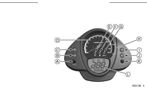
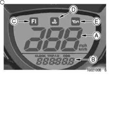
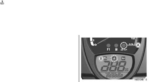
Meter Instruments
A. MODE Button |
Free |
D. Tachometer |
|
B. Neutral Indicator Light |
|
C. Left Turn Signal Indicator |
|
Light |
|
E. FI Indicator Light |
Download |
F. Fuel Level Warning Light
G. Warning Light
H. Red Zone
I. Right Turn Signal Indicator
Light
J. High Beam Indicator Light
K. RESET Button
L. LCD (Speedometer, Clock,
Trip meter A/B, Odometer,
Warning Symbols)

16 GENERAL INFORMATION |
|
|
Tachometer Gauge: |
not operate correctly, have it inspected |
|
The tachometer shows the engine |
by an authorized Kawasaki dealer. |
|
speed in revolutions per minute (r/min, |
|
|
CAUTION |
||
rpm). On the right side of the tachome- |
||
ter face is a portion called the "red |
Engine r/min.org(rpm) should not |
|
.ClassicCycles |
||
zone". Engine r/min (rpm) in the |
be allowed to enter the red zone; |
|
red zone is above maximum recom- |
operation in the red zone will |
|
mended engine speed and is also |
overstress the engine and may |
|
above the range for good performance. |
cause serious engine damage. |
|
When ignition key is turned to ON , |
|
|
the tachometer needle momentarily |
|
|
point to the last reading to check its op- |
|
|
eration. If the tachometer needle does |
|
|
www |
|
|
GENERAL INFORMATION 17
LCD |
(Speedometer, |
Clock, |
|
|
|
||||
|
|
Odometer, Trip Meters, Warning |
|
|
|
||||
|
|
Symbols): |
|
|
|
|
|
||
|
The LCD (Liquid Crystal Display) lo- |
|
|
|
|||||
cated in the tachometer face is used |
|
|
|
||||||
to display the speedometer, Clock, |
A. Clock |
|
|
||||||
odometer, Trip Meters A/B, and the fol- |
B. Odometer |
|
|
||||||
lowing Warning Symbols:Freeoil pressure |
C. Trip Meter A |
|
|
||||||
( |
|
), |
coolant temperature ( |
|
), and |
D. Trip Meter B |
|
|
|
|
|
|
|
||||||
|
|
E. Push MODE Button |
|||||||
|
|
||||||||
fuel injection (FI). Pushing the MODE |
|
NOTE |
|||||||
button shifts the display through the |
|
||||||||
following four modes: CLOCK, ODO, |
For safe operation do not press the |
||||||||
and TRIP A/B. When the ignition key is |
|||||||||
MODE button while riding. |
|||||||||
turned to ON , all the LCD segments |
|||||||||
|
|
|
|||||||
are displayed for three seconds, then |
|
|
|
||||||
the clock or meters operate normally |
|
|
|
||||||
|
|
|
|
Download |
|
|
|||
depending on the mode selected. |
|
|
|
||||||
18 GENERAL INFORMATION |
|
|
|
Digital Meter |
Mile/Km Display - |
||
|
|
Mile/Km Display can alternate be- |
|
|
|
||
|
|
tween English and metric modes (mile |
|
|
|
and km) in the digital meter. Make sure |
|
|
|
that km or mile according to local reg- |
|
|
|
.org |
|
|
|
ulations is correctly displayed before |
|
|
|
riding. |
|
|
|
|
NOTE |
|
|
Do not operate the vehicle with the |
|
|
|
digital meter displaying in the wrong |
|
|
|
unit (km or mile). Shift the km/mile |
|
A. Speedometer |
display in the digital meter as follows. |
||
B. Clock, Trip Meter A/B, Odometer |
Display the odometer in the digital |
||
C. FI Warning Symbol |
|||
D. Coolant Temperature Warning Symbol |
meter. |
|
|
E. Oil Pressure Warning Symbol |
|
|
|
.ClassicCycles |
|
||
NOTE |
|
|
|
www |
|
|
|
Do not shift the digital meter display |
|
|
|
while riding for safe operation.
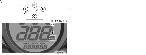
The km/mile display shifts by pushing |
|
GENERAL INFORMATION 19 |
|||
The km/mile display shifts as follows. |
|||||
the RESET button while the MODE |
|
|
|
||
button pushed in. |
|
|
|
||
|
|
|
|
|
|
|
Free |
|
|
|
|
|
|
A. Mile Display |
|
|
|
|
|
|
B. Km Display |
|
|
|
Download |
|
|
||
|
|
|
C. Push RESET Button with MODE Button in |
||
|
|
|
|
NOTE |
|
|
|
|
The data is maintained even if the |
||
|
|
|
battery is disconnected. |
||
A. Km/Mile Display |
|
|
Spee ometer - |
||
|
|
|
|||
|
|
|
The speedometer shows the speed |
||
|
|
|
of the vehicle in digital value. |
||
20 GENERAL INFORMATION |
Push |
|
|
|
|
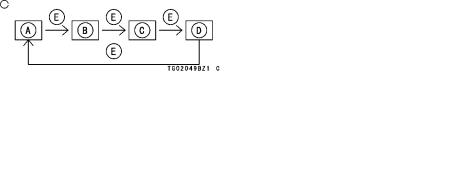
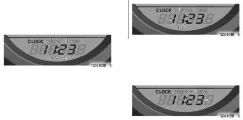
Clock - |
the |
"RESET" button. |
The |
||
To adjust the hours and minutes: |
hour |
display only flashes. |
Push |
||
Turn the ignition key to "ON". |
|
|
.org |
|
|
the "MODE" button to advance the |
|||||
Push the "MODE" button to display |
hours. |
|
|
||
the clock. |
|
|
|
|
|
.ClassicCycles |
|
||||
Push the "RESET" button for more |
|
|
|
|
|
than two seconds. Both the hour and |
|
|
|
|
|
minute displays start flashing. |
|
|
|
|
|
|
|
Push |
the |
"RESET" button. |
The |
|
|
hour display stops flashing and the |
|||
|
|
minute display starts flashing. Push |
|||
|
|
the "MODE" button to advance the |
|||
www |
minutes. |
|
|
||
|
|
|
|
||
|
|
|
|
||
|
|
|
|
||
GENERAL INFORMATION 21
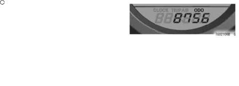
Push the "RESET" button. Both the |
Odometer - |
|
|
hour and minute displays start flash- |
The odometer shows the total dis- |
||
ing again. |
|
tance in kilometers or miles that the ve- |
|
Push the "MODE" button. The dis- |
hicle has been ridden. This meter can- |
||
plays stop flashing and the clock |
not be reset. |
|
|
starts working. |
|
|
|
|
|
|
|
NOTEFree |
|
|
|
Pushing the MODE button momen- |
|
|
|
tarily advances the hour or minute |
|
|
|
step by step. Pushing and h ld- |
|
|
|
|
NOTE |
||
ing the button advance the hour or |
|
||
minute continuously. |
Download |
|
|
|
The data is maintained even if the |
||
The clock works normally from the |
battery is disconnected. |
||
back-up power while the ignition |
When the figures come to 999999, |
||
switch is turned off. |
they are stopped and locked. |
|
When the battery is disconnected, |
||
|
||
the clock resets to 1:00 and starts |
|
|
working again when the battery is |
|
|
connected. |
|
22 GENERAL INFORMATION |
|
||
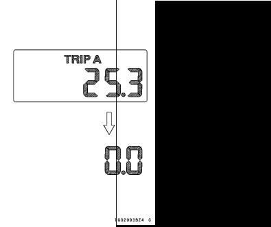
Trip Meter - |
|
|
|
|
|
||
The trip meters show the distance in |
.org |
||
kilometers (miles) traveled since they |
|||
|
|||
were last reset to zero. |
|
||
TRIP A: 0.0 |
999.9 |
|
|
TRIP B: 0.0 |
.ClassicCycles |
||
9999.9 |
|
||
To reset the trip meter: |
|
||
Push the MODE button to display |
|
||
the trip meter A or B. |
|
||
Push the RESET button and hold it |
|
||
in. |
|
|
|
After two seconds, the figure display |
|
||
turns to 0.0, and then starts counting |
|
||
when the vehicle is operated. The |
|
||
meter counts until it is next reset. |
|
||
|
www |
|
|
|
|
|
|
|
|
|
|
GENERAL INFORMATION 23 |
NOTE |
|
|
Warning/Indicator Lights: |
|
The data is maintained by the back |
|
: The fuel level warning light in |
||
-up power if the ignition key is turned |
the tachometer goes on and FUEL |
|||
off. |
|
|
flashes in the digital meter when only |
|
When the trip meter is reset while the |
3.5 L (0.9 US gal) of fuel remains. Re- |
|||
vehicle is stopped, it starts counting |
fuel at the earliest opportunity when |
|||
as soon as the vehicle starts moving. |
the fuel level warning light goes on and |
|||
When the trip meterFreereaches 999.9 |
FUEL flashes. |
|||
(TRIP A) or 9999.9 (TRIP B) while |
|
|
|
|
|
|
|
||
|
Download |
|||
running, the meters reset to 0.0 and |
|
|
||
continues counting. |
|
|
|
|
When the battery is disconnected, |
|
|
||
the meter display resets to 0.0. |
|
|
||
|
|
|
|
|
A.Fuel Level Warning Light
B.Flash
24 GENERAL INFORMATION |
|
|
|||||
|
|
|
|
NOTE |
|
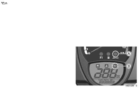
: The oil pressure warning light in |
|
|
|
|
|
|
|||
|
When |
pushing the MODE button |
the tachometer and symbol in the LCD |
||||
|
while FUEL is displayed, the dis- |
|
.org |
||||
|
goes on whenever the oil pressure is |
||||||
|
play can be shifted to odometer, trip |
dangerously low o the ignition key is |
|||||
|
meter, or clock mode. |
in the ON positi n with the engine not |
|||||
flashes. |
.ClassicCycles |
||||||
N: When the transmission is in neutral, |
running, and goes off when the engine |
||||||
the neutral indicator light is lit. |
oil pressur is high enough. Refer to |
||||||
|
|
|
|
|
|
the Maintenance and Adjustment chap- |
|
|
|
|
: When the headlight is on high |
ter for more detailed engine oil informa- |
|||
beam, the high beam indicator light is |
|
tion. |
|||||
lit. |
|
|
|
|
|||
|
|
|
|
|
|||
|
|
: When the turn signal switch is |
|
|
|
||
pushed to the left or right, the cor- |
|
|
|
||||
responding turn signal indicator light |
|
|
|
||||
|
|
|
|
www |
|
|
|
|
|
|
|
|
|
|
|
|
|
GENERAL INFORMATION 25 |
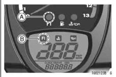
FI: The fuel injection (FI) indicator light |
|
|
|
||
in the tachometer and symbol in the |
|
|
LCD goes on when the ignition key is |
|
|
turned to ON and goes off soon after |
|
|
ensuring that its circuit functions prop- |
|
|
erly. The indicator light also goes on |
|
|
whenever the troublesFreeoccur in digital |
|
|
fuel injection system (DFI). If the indica- |
|
|
|
Download |
|
tor light comes on, have the DFI system |
|
|
checked by an authorized Kawasaki |
A. FI Indicator Light |
|
dealer, |
light flashes, first |
B. FI Warning Symbol |
When the indicator |
|
|
and then
26 GENERAL INFORMATION |
|
|
|
|
||
|
|
|
|
|||
|
: The coolant temperature warning |
|
CAUTION |
|||
light in the tachometer and symbol in |
|
|
|
|
||
Do not let the en ine continue |
||||||
the LCD goes on whenever the coolant |
||||||
running when the warning light |
||||||
temperature rises to 115°C (239°F) |
||||||
flashes. Pr |
|
l nged engine oper- |
||||
when the motorcycle is in operation. |
|
|||||
|
|
org |
||||
This warns the operator that the coolant |
ation will result. |
in severe dam- |
||||
age from overheating. |
||||||
temperature is too high. If the warn- |
||||||
ing light goes on stop the engine and |
|
|
|
|
||
check the coolant level in the reserve |
|
|
|
|
||
tank after the engine cools down. |
|
|
|
|
||
|
.ClassicCycles |
|
|
|||
|
www |
|
||||
|
A. Coolant Temperature Warning Light |
|||||
|
B. Coolant Temperature Warning Symbol |
|||||
|
|
|
|
|
||
|
|
GENERAL INFORMATION 27 |
|
Key |
|
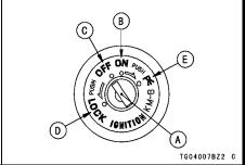
Ignition Switch/Steering Lock |
|
This motorcycle has a combination |
This is a four-position, key-operated |
||
key, which is used for the ignition |
switch. The key can be removed from |
||
switch/steering lock, seat lock, and fuel |
the switch when it is in the OFF, LOCK, |
||
tank cap. |
|
or P (Park) position. |
|
Blank keys are available at your |
|
|
|
|
|
||
Kawasaki dealers. Ask your dealer to |
|
|
|
make any additionalFreespar keys you |
|
|
|
may need, using your original key as a |
|
|
|
master. |
Download |
|
|
|
|
||
|
|
A. Ignition Switch/Steering Lock |
|
B. ON position
C. OFF position
D. LOCK position
E. P (Park) position
28 GENERAL INFORMATION
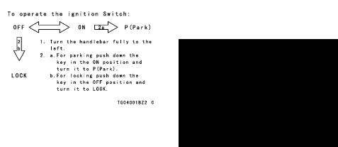
OFF |
Engine off. |
All electrical |
|
the engine immediately after turning |
circuits off. |
|
|
the ignition key to ON . |
|
|
|
|
||
|
|
|
|
If you leave the P (Park) position on |
ON |
Engine on. |
All electrical |
||
equipment can be used. |
|
for a long time (one hour), the battery |
||
|
|
|
|
may become t tally discharged. |
|
Steering locked. Engine off. |
|||
LOCK |
|
.org |
||
All electrical circuits off. |
|
|
||
|
|
|
||
|
Steering locked. Engine off. |
|
|
|
P(Park) |
License plate, tail, and city |
|
|
|
lights on and turn signals can |
|
|
||
|
be used. All other electrical |
|
|
|
|
circuits cut off. |
|
|
|
|
NOTE |
|
|
|
The city, tail and license plate ights |
|
|
||
are on whenever the ignition key is |
|
|
||
|
|
.ClassicCycles |
||
in the ON position. One headlight |
|
|
||
|
www |
|
|
|
goes on when the starter button is released after starting the engine. To avoid battery discharge, always start
|
|
|
|
|
GENERAL INFORMATION 29 |
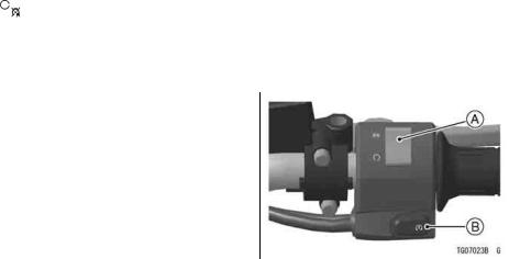
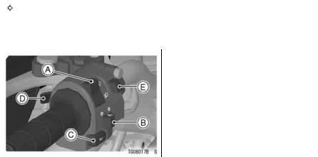
Right Handlebar Switches |
NOTE |
||||
Engine Stop Switch: |
|
|
Although the engine stop switch |
||
In addition to the ignition switch, |
stops the engine, it does not turn off |
||||
the engine stop switch must be in |
all the electrical circuits. Ordinarily, |
||||
the |
|
position for the motorcycle to |
the ignition switch should be used to |
||
gency use. If someFreeem rg ncy re- |
stop the engine. |
||||
operate. |
|
|
|
||
The engine stop switch is for emer- |
|
||||
quires stopping the engine, move the |
|
||||
|
|
|
|
Download |
|
engine stop switch to the |
|
positi n. |
|
||
|
|
||||
|
|
|
|
|
|
A. Engine Stop Switch
B. Starter Button

30 GENERAL INFORMATION
Starter Button: |
Left Handlebar Switches |
|||||||
The starter button operates the elec- |
Dimmer Switch: |
|
|
|
|
|
||
tric starter when the transmission is in |
.org |
|
|
|||||
High or low beam can be selected |
||||||||
neutral. |
with the dimme |
switch. |
When the |
|||||
Refer to the Starting the Engine sec- |
headlight is on high beam ( |
|
), the |
|||||
.ClassicCycles |
|
|
|
|
|
|||
tion of the "How to Ride the Motorcycle" |
high beam indicator light is lit. |
|||||||
chapter for starting instructions. |
High beam.......( |
|
|
|
) |
|
|
|
|
|
|
|
|
||||
|
Low beam.......( |
|
|
) |
|
|
||
www |
|
|
|
|
|
|
|
|
|
|
|
|
GENERAL INFORMATION 31 |
|||
NOTE |
Turn Signal Switch: |
|
|||||
When the headlight is on high beam, |
When the |
turn |
signal switch is |
turned |
|||
both head lights are lit. When the |
to the left ( |
|
) or right ( |
|
), the |
||
headlight is on low beam, only one |
corresponding turn signal flashes on |
||||||
headlight is lit. |
Free |
and off. |
|
|
|
||
|
To stop flashing, push the switch in. |
||||||
|
|
|
|||||
|
|
|
Horn Button: |
|
|
|
|
|
|
|
When the horn button is pushed, the |
||||
|
Download |
|
|
|
|||
|
|
|
horn sounds. |
|
|
|
|
|
|
|
Passing Button: |
|
|||
|
|
|
When the passing button is pushed, |
||||
|
|
|
the headlight high beam (passing |
||||
|
|
|
beam) comes on to signal the driver of |
||||
|
|
|
the vehicle ahead that you are about to |
||||
|
|
|
pass him. The passing light shuts off |
||||
|
|
|
as soon as the button is released. |
||||
A. Dimmer Switch |
|
|
|||||
|
|
|
|
|
|
|
|
B. Turn Signal Switch |
|
|
Hazard Switch: |
|
|
|
|
C. Horn Button |
|
|
If an emergency requires you to park |
||||
D. Passing Button |
|
|
|||||
E. Hazard |
|
|
on the highway shoulder, turn on the |
||||
hazard lights to warn other drivers of your location.
32 GENERAL INFORMATION |
|
|
|
|
Push in the hazard switch with the |
Brake/Clutch Lever Adjusters |
|||
ignition switch in the ON or P (Park) |
There is an adjuster on both the |
|||
position. All the turn signals and turn |
.org |
|||
brake and clutch levers. Each adjuster |
||||
signal indicator lights will flash on and |
has 5 positions so that the released |
|||
off. |
|
|
|
lever position can be adjusted to suit |
|
|
|
ClassicCycles |
|
|
CAUTION |
|
|
the operator hands. Push the lever |
|
|
|
forward and turn the adjuster to align |
|
If you leave the switch on for a |
the number with the arrow mark on the |
|||
long time, the battery may be- |
lever holder. |
|||
come totally discharged. So be |
|
|||
careful not to use the hazard |
|
|||
lights for more than 30 minutes. |
|
|||
|
|
. |
|
|
|
www |
|
|
|
 Loading...