


ASSEMBLY INSTRUCTIONS
for :
PRO-II
Parts: 01000 and 01040
12_1.1
®
www.kargomaster.com
(916) 638-8703
• 11261 Trade Center Drive • Rancho Cordova, CA 95742 •
(800) 343-7486
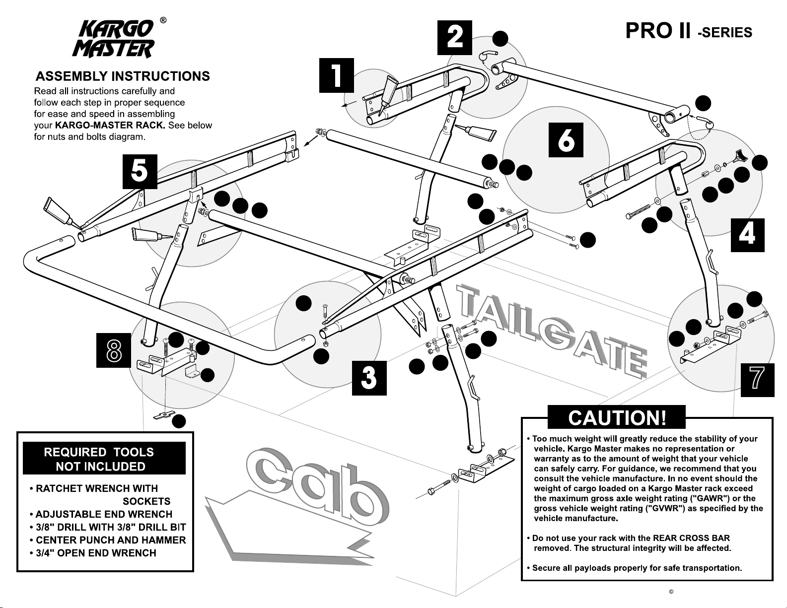
1
PASSENGER SIDE CHANNEL
2
J
All models for
trucks without shells.
J
E
H
W
4
S
7
7
P
O
5
A
8
8
P
O
H
G
V
C
I
U
R
M
L
F
U
H
DRIVER SIDE CHANNEL
Q
U
N
U
K
H
I
3
B
1/2", 9/16", & 3/4"
2012 KargoMaster-'Pro 2' 12_1.1
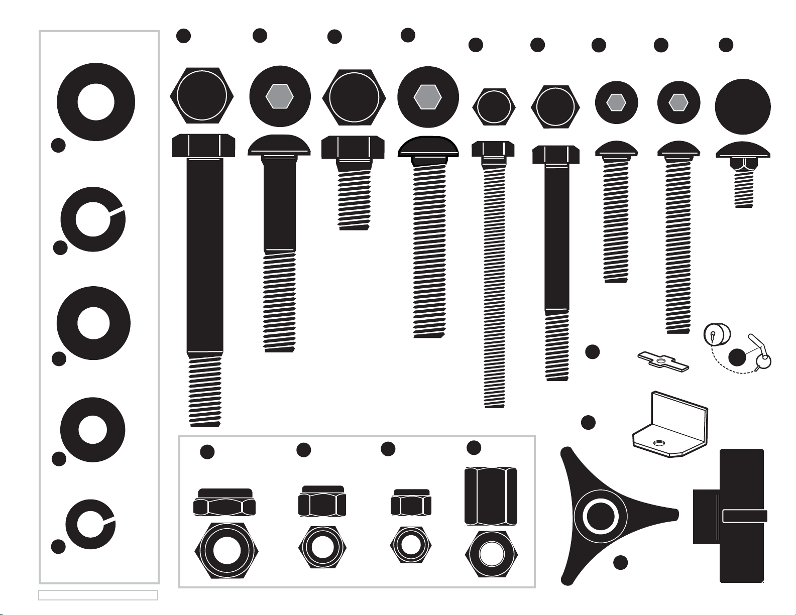
H
(12 ea.)
1/2" SAE Flat Washer
O
(5 ea.) 1/2" Lock Washer
S
(4 ea.)
1/2" x 3-3/4"
Hex Bolt
G
(2 ea.)
1/2" x 2 3/4"
Button Head Bolt
P
1/2" x 1"
Hex Bolt
(4 ea.)
V
(6 ea.)
1/2" x 2 1/2"
Button Head Bolt
(2 ea.)
K
3/8" x 3 1/2"
Tap Bolt
F
3/8" x 3"
Hex Bolt
(4 ea.)
(8 ea.)
D
3/8" x 1 3/4"
Button Head
(2 ea.)
A
3/8" x 16 x 2 1/2"
Button Head
(4 ea.)
Q
5/16" x 3/4"
Carriage Bolt
U
(28 ea.) 3/8" SAE Flat Washer
L
(9 ea.) 5/16" Flat Washer
E
(2 ea.) 3/8" Lock Washer
©2012 KARGO MASTER - Pro 2 12_1.1
I
(7 ea.)
1/2" Jam Nut
M
R
(12 ea.)
3/8" Lock Nut 5/16" Lock Nut
(9 ea.)
N
(2 ea.)
3/8" Coupling Nut
B
C
(2 ea.)
3/8” T Nut
(6 ea.)
Bed Rail
Clamps
W
(2 ea.)
J
(2 ea.)
Rear Pin
& Cap
Plastic Knob

Pro 2 12_1.1
E6000 APPLICATION
Apply a healthy air tight bead of E6000
around every swedged joint as shown, to
prevent moisture from leaking into and out
of the joint. If this is not done properly, the
inside surface of the tubes can rust and
rusty water can leak out. Maintain this joint
seal throughout the life of your rack.
STEP 1
#1 = Cover entire swedge joints with E6000 and
join FRONT and REAR side channels together.
Be sure the connecting plates overlap and bolt
together with boltsQ, washersL and lock nutsM
M
L
%
Smooth E6000 at swedged joint & holes
%
0
0
0
6
E
Swedged joint & holes
STEP 2
#
1= Slide REAR BAR on to REAR SIDE BEAMS
$RIVERSIDE
04
#HANNEL
2= Install LOCK PIN CAP J onto Rear Bar D by
#
soaking plastic cap in hot soapy water, dry, then add E6000
to plastic and Insert.
#3= Fully insert LOCK PINS J completely to the bend of the pin.
D
0ASSENGERSIDE
06
#HANNEL
D
J
STEP 3
#1= Cover entire swedged joint surfaces with E6000,
Slide FRONT CROSS BAR into FRONT SIDE BEAMS
A
Q
06
J
G
03
E6000
$RIVERSIDE
03 05
#HANNEL
#2= BOLT TOGETHER using G & I.
The allen wrench is included
in the package.REAR SIDE BEAMS
0ASSENGER
SIDE#HANNEL
A
I

STEP 4
3
4
/
Pro 2 12_1.1
Leg Cup
E6000
#1= All 4 legs are identical.
./4% Steps #4 & #5 are more easily
completed with rack turned upside down.
Cover entire swedged joint surfaces with E6000,
Then insert the swedged end of each leg ,rope
hooks facing outward, into the short leg cup.
Repeat this operation for each leg, leaving FRONT
LEGS unbolted.
#2= Bolt REAR LEGS and
REAR BAR BRACE (as shown)
01
K
01
E6000
E6000
E6000
01
01
W
U
E
N
01
U
01
STEP 5
#1= At each end of CENTER CROSS BAR ,
start BOLTS & WASHERS. Be sure to include
both flat and lock WASHERS.
Leave loose enough so that
BOLT shaft can be slid into
the FRONT SLOTTED BRACKET
as shown in #3 below.
#2= On one side of rack, slide BOLTS & WASHERS
into FRONT SLOTTED BRACKET as shown in #3
below.
On the other side of the rack, slide the BOLT &
WASHERS into FRONT SLOTTED BRACKET. Bolt
CENTER CROSS BAR
BRACES and LEG
together(snug only).
Returning to the other side
of the rack, bolt the
CENTER CROSS BAR
BRACES
and LEG together (snug only)
F
B
U
B
#3= With an open end
3/4" wrench, snug the
CENTER CROSS BAR
B
BOLTS on each side of
the rack.
B
R
H
O
P

STEP 6
Pro 2 12_1.1
#1= Turn rack right side up now. At each end of CENTER CROSS BAR , start BOLTS & WASHERS
P O
, , . Be sure to include both flat and lock WASHERS. Leave loose enough so that BOLT shaft
H
C
can be slid down into the CLAMP PLATE SLOTTED BRACKET as shown below.
C
H
O
P
08
09
01
H
I
S
I
#2= Loosely attach REAR FOOTPLATES
to REAR LEGS (as shown) snug only
08
09
INSIDE
TRUCK BED

STEP 7
Pro 2 12_1.1
#1=
Position FRONT FOOTPLATES on the truck bedrail, as far
forward as possible. Determine which pre-drilled hole (if any) falls over
the stake pocket. If none of the pre-drilled holes fall over the stake
pocket, mark and drill a hole in the foot plate that is approximately over
the center of the stake pocket. Put bolt A through FOOTPLATE and start T Nut B
as shown. Maneuver T Nut B inside the stake pocket, push the FOOTPLATE forward
against the bulkhead, and tighten the T nut up against the underside of the
truck bed rail. Secure the rear of the front FOOTPLATE to the bedrail using
Bolt V and Bed Rail Clamp C as shown.
Note: If you prefer to mount the FOOTPLATES by drilling through the truck
bedrail, locate the FOOTPLATES as per above, and attach using included
fasteners D, U, and R. We recommend using the pre-drilled hole at the rear
of the FOOTPLATES. You will have to locate and drill a second hole in the
FOOTPLATE, get as close to the leg as possible. Be sure you can access the nut.
A
V
TRUCK
CAB
T-nut
B
FOOTPLATE
(front)
TRUCKs’
Front
Stake
Pocket
Bed Rail Clamp
BEDRAIL
C

STEP 8
Pro 2_8.1.1
#1=
Lift the rack up onto the truck bedrail. Loosely attach the front legs to
the secured FRONT FOOTPLATES as shown in STEP 7. Position the REAR
FOOTPLATES against the bedrail. Attach the REAR FOOTPLATES to the
truck bedrail using bedrail clamps as shown in the illustration.
Note: If you prefer to mount the FOOTPLATES by drilling 3/8" holes through
the truck bedrail, locate the FOOTPLATES as per above, and attach using
included fasteners V, U, and R. We recommend using the pre-drilled hole at
the rear of the FOOTPLATES. You will have to locate and drill a second 3/8"
hole in the FOOTPLATE, as close to the leg as possible.

STEP 9
Pro 2 12_1.1
#1= Tighten down ALL NUTS AND BOLTS, except LEG FOOTPLATES and CENTER CROSS BAR .
DO NOT OVER TIGHTEN ON DOUBLE WALL BED CONSTRUCTION, AS THIS MAY DEFORM THE
SHEET METAL OF THE PICKUP BED!
C
#2= Center RACK over bed and tighten FRONT
MOUNT BOLTS. On REAR MOUNT BOLTS be sure
LOCK PINS slide IN & OUT smoothly and freely
before tightening the rear BOLTS.
#3= Snug bolts in CENTER CROSS BAR .
J
C
#4= Modern truck beds are made from thin steel with
limited load bearing capacity. Approximately 75% of
the rack load is carried by the front legs. Because the
rack is wider at the bottom than the top, overhead
loads tend to push the bed walls down and apart.
If you expect to carry heavy loads,
we strongly suggest that you purchase
and install OPTIONAL BED SUPPORTS
as shown below.
THAT'S IT!
You're ready to
use and enjoy your
KARGO MASTER
TRUCK RACK!
©2012 KARGO MASTER - Pro 2 12_1.1
INSIDE BED WALL
8
3"
3/8"
(OPTIONAL
BED SUPPORT)
Part # 31040
View full line of accessories available at
www.kargomaster.com

DON'T OVERLOAD YOUR VEHICLE!
LBS.
LBS.
@
@
WEIGHT CARRIED ABOVE THE FLOOR OF THE TRUCK BED (E.G. ON AN
OVERHEAD TRUCK RACK) WILL SIGNIFICANTLY INCREASE THE
VEHICLE'S TENDENCY TO OVERTURN. ALWAYS KEEP HEAVY LOADS
EVENLY DISTRIBUTED AND AS LOW AS POSSIBLE. IT IS IMPORTANT TO
NOTE THAT THE KARGO MASTER RACK LOAD BEARING CAPACITY OF
1700 LBS. MAY BE GREATER THAN YOUR TRUCK'S GAWR OR GVWR
CAPACITY, AND IS PROBABLY GREATER THAN THE WEIGHT THAT CAN
BE SAFELY CARRIED OVERHEAD. RETIGHTEN ALL BOLTS AFTER FIRST
USE, PERIODICALLY CHECK BOLTS FOR TIGHTNESS.
100" = X3 lbs.
V
O
35" =
x1 lbs.
E
R
T
U
R
N
F
O
R
C
E
For TECHNICAL SUPPORT Call:
1.800.343.7486
www.kargomaster.com
HOURS: Monday- Friday 8:30 A.M. to 5:00 P.M. ( PACIFIC )
 Loading...