

Page 1
BP 3 Home & Garden
BP 4 Home & Garden
BP 5 Home & Garden
BP 7 Home & Garden
Deutsch 5
English 12
Français 19
Italiano 26
Nederlands 33
Español 40
Português 47
Ελληνικά 54
Türkçe 61
59679610 08/17
Page 2
2
Page 3
3
Page 4
Page 5
Lesen Sie vor der ersten Benutzung Ihres
und die beiliegenden Sicherheitshinweise. Handeln Sie
danach. Bewahren Sie beide Hefte für späteren Gebrauch oder für Nachbesitzer auf.
Gerätes diese Originalbetriebsanleitung
Inhaltsverzeichnis
Inhaltsverzeichnis DE 1
Allgemeine Hinweise DE 1
Gefahrenstufen DE 1
Umweltschutz DE 1
Anschluss an das öffentliche Trinkwas-
sernetz DE 2
Sicherheitshinweise DE 2
Bedienung DE 2
Pflege, Wartung DE 3
Transport DE 3
Lagerung DE 3
Hilfe bei Störungen DE 4
Anwendungshinweise DE 5
Technische Daten DE 6
EU-Konformitätserklärung DE 7
Allgemeine Hinweise
Voraussetzungen für die Standsicherheit
몇 VORSICHT
Vor allen Tätigkeiten mit oder am Gerät Standsicherheit
herstellen, um Unfälle oder Beschädigungen durch Umfallen des Geräts zu vermeiden.
Die Standsicherheit des Gerätes ist gewährleistet,
wenn es auf einer ebenen Fläche abgestellt wird.
Garantie
In jedem Land gelten die von unserer zuständigen Vertriebsgesellschaft herausgegebenen Garantiebedingungen. Etwaige Störungen an Ihrem Gerät beseitigen
wir innerhalb der Garantiefrist kostenlos, sofern ein Material- oder Herstellungsfehler die Ursache sein sollte.
Im Garantiefall wenden Sie sich bitte mit Kaufbeleg an
Ihren Händler oder die nächste autorisierte Kundendienststelle.
Bestimmungsgemäße Verwendung
Dieses Gerät wurde für den privaten Gebrauch entwickelt und ist nicht für die Beanspruchungen des gewerblichen Einsatzes vorgesehen.
Der Hersteller haftet nicht für eventuelle Schäden, die
durch nicht bestimmungsgemäßen Gebrauch oder falsche Bedienung verursacht werden.
Das Gerät ist vorwiegend zum Einsatz in Haus und Garten bestimmt.
Die Haus- & Gartenpumpen schalten sich bei Wasserbedarf automatisch ein und aus. Damit eignen sie sich
sowohl für Garteneinsätze als auch für Anwendungen
innerhalb des Hauses. Sie lassen sich perfekt zur Versorgung von Waschmaschinen oder WC-Spülungen im
Haus einsetzen, zum Beispiel in Verbindung mit einer
Zisterne. Daneben stellt der konstante Betriebsdruck
der Pumpen auch eine zuverlässige Gartenbewässerung sicher.
몇 VORSICHT
Beschädigungsgefahr! Die Pumpe ist nicht zur Verstärkung des vorhandenen Leitungsdrucks geeignet.
Zugelassene Förderflüssigkeiten
Brauchwasser
Brunnenwasser
Quellwasser
Regenwasser
Schwimmbadwasser (bestimmungsgemäße Do-
sierung der Additive vorausgesetzt)
몇 VORSICHT
Wasser, das mit diesem Gerät gefördert wurde, ist
kein Trinkwasser!
몇 WARNUNG
Nicht gefördert werden dürfen ätzende, leicht brennbare oder explosive Stoffe (z.B. Benzin, Petroleum, Nitroverdünnung), Fette, Öle, Salzwasser und Abwasser aus
Toilettenanlagen und verschlammtes Wasser, das eine
geringere Fließfähigkeit als Wasser hat.
Das Gerät ist mit einer Trockenlaufsicherung ausgestattet und nicht für einen ununterbrochenen Dauerbetrieb
(z.B. Hebeanlage, Springbrunnenpumpe) geeignet.
Die Temperatur der geförderten Flüssigkeit darf 35°C
nicht überschreiten
Gefahrenstufen
GEFAHR
Für eine unmittelbar drohende Gefahr, die zu schweren
Körperverletzungen oder zum Tod führt.
몇 WARNUNG
Für eine möglicherweise gefährliche Situation, die zu
schweren Körperverletzungen oder zum Tod führen
könnte.
몇 VORSICHT
Hinweis auf eine möglicherweise gefährliche Situation,
die zu leichten Verletzungen führen kann.
ACHTUNG
Hinweis auf eine möglicherweise gefährliche Situation,
die zu Sachschäden führen kann.
Umweltschutz
Hinweise zu Inhaltsstoffen (REACH)
Aktuelle Informationen zu Inhaltsstoffen finden Sie unter:
www.kaercher.de/REACH
Die Verpackungsmaterialien sind recyclebar. Bitte
Verpackungen umweltgerecht entsorgen.
Elektrische und elektronische Geräte enthalten oft
Bestandteile, die bei falschem Umgang oder falscher Entsorgung eine potentielle Gefahr für die
menschliche Gesundheit und die Umwelt darstellen können. Für den ordnungsgemäßen Betrieb
des Gerätes sind diese Bestandteile jedoch notwendig. Mit diesem Symbol gekennzeichnete Geräte dürfen nicht mit dem Hausmüll entsorgt werden.
Altgeräte enthalten wertvolle recyclebare Materialien, die einer Verwertung zugeführt werden sollten. Batterien und Akkus enthalten Stoffe, die
nicht in die Umwelt gelangen dürfen. Bitte Altgeräte sowie Batterien oder Akkus umweltgerecht entsorgen.
– 1
5DE
Page 6
Anschluss an das öffentliche
Trinkwassernetz
Bitte beachten Sie beim Anschluss dieses Produktes an
das Trinkwassernetz die Anforderungen der EN 1717
und wenden Sie sich bei eventuellen Fragen an Ihren
Sanitärfachbetrieb.
Sicherheitshinweise
Vor Inbetriebnahme der Pumpe beiliegende Sicherheitshinweise beachten!
Bedienung
Einstellungen
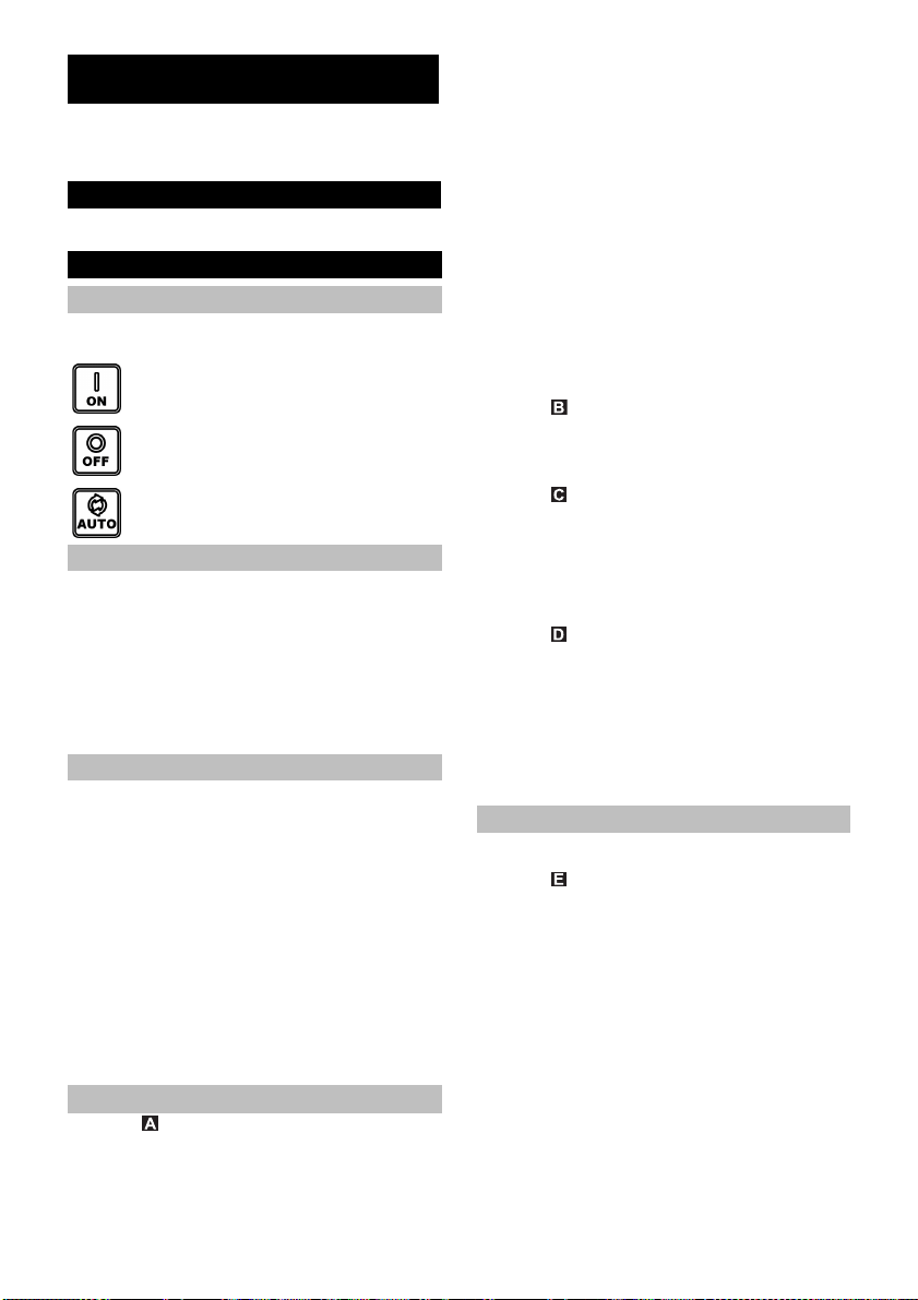
Mit dem EIN-/AUS-Schalter lassen sich die folgenden
drei Betriebszustände schalten:
Schalterstellung I/On
Dauerbetrieb
Schalterstellung 0/Off
Aus
Schalterstellung Auto
Automatikbetrieb
Funktionsweise
Im Automatik-Modus halten die Haus- & Gartenpumpen
den Druck im System automatisch aufrecht. Sinkt der
Druck unter ca. 0,13 MPa (1,3 bar), wird die Pumpe gestartet. Die Pumpe läuft solange der Durchfluss
> ca. 60 l/h beträgt. Wird die Wasserentnahme beendet,
geht die Pumpe nach kurzer Nachlaufzeit in den StandBy-Zustand. Das System steht nun unter Druck. Bei
Wasserentnahme und dem daraus resultierenden
Druckabfall startet die Pumpe erneut.
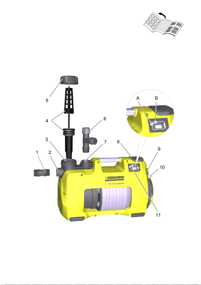
Gerätebeschreibung
1 Anschluss-Adapter für Pumpen G1
2 Anschluss G1 (33,3 mm) Saugleitung (Eingang)
3 Einfüllstutzen
4 Vorfilter und integriertes Rückschlagventil
5 Deckel
6 2-Wege Anschluss-Adapter für Pumpen G1
7 Anschluss G1 (33,3 mm) Druckleitung (Ausgang)
8 EIN-/AUS-Schalter
9 Kabelaufbewahrung und Netzanschlusskabel mit
Stecker
10 Kabelclip
11 Fehleranzeige
A Fehler an Saugseite
B Fehler an Druckseite
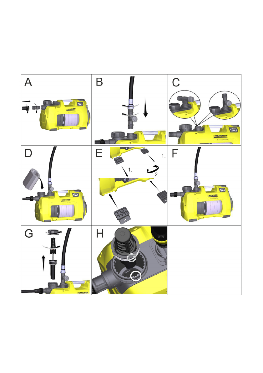
Vorbereiten
Abbildung
Anschluss-Adapter in Sauganschluss der Pumpe
(Eingang) schrauben.
Von Hand anziehen.
Vakuumfesten Saugschlauch anschließen.
Hinweis
Um die Wiederansaugzeit zu verkürzen, Saugschlauch
mit Rückflussstopp verwenden. Dieser verhindert das
6 DE
Entleeren des Saugschlauchs nach der Verwendung
(siehe Zubehör).
Rückflussstopp nicht direkt an der Pumpe (saug- oder
druckseitig) installieren.
Wenn sandiges Wasser gefördert werden soll, empfehlen wir dringend einen zusätzlichen Vorfilter zu verwenden (siehe Sonderzubehör). Diesen bitte an der Saugseite der Pumpe, zwischen Saugschlauch und Pumpe,
montieren.
Bitte Original Kärcher Saugleitungen, Filterkomponenten und Schlauchanschlüsse verwenden. Bei Verwendung von Bauteilen anderer Hersteller kann es zu Fehlfunktionen beim Ansaugen der Förderflüssigkeit kommen, insbesondere bei Verwendung von Bajonett-Verbindungssystemen.
Bei Haus- oder Festinstallation keine Schnellkupplungen sondern verschraubte Verbindungen verwenden.
Abbildung
Anschluss-Adapter in Druckanschluss der Pumpe
(Ausgang) schrauben.
Von Hand anziehen.
Druckleitung anschließen.
Abbildung
Der 2-Wege-Adapter ermöglicht den gleichzeitigen Betrieb von zwei Geräten (z.B. Waschmaschine oder
Sprinkler). Er kann so montiert werden, dass entweder
beide Ausgänge seitlich oder ein Ausgang seitlich und
ein Ausgang oben verwendet werden. Bei der Verwendung von nur einem Ausgang kann der nicht benötigte
Ausgang mit der beiliegenden Verschlusskappe verschlossen werden.
Abbildung
Deckel am Einfüllstutzen abschrauben und Wasser
bis zum Rand einfüllen.
Deckel von Hand bis zum Anschlag auf den Einfüll-
stutzen schrauben.
Vorhandene Absperrventile in der Druckleitung öff-
nen.
Hinweis
Bereits geringe Undichtigkeiten führen zu Fehlfunktionen.
Festinstallation
Bei einer Festinstallation kann die Pumpe auf einer geeigneten Oberfläche festgeschraubt werden.
Abbildung
Gummifüße auf beiden Seiten des Gehäuses her-
ausziehen und drehen.
Gummifüße wieder in Gehäuse einsetzen.
Mit geeigneten Schrauben auf ebener Oberfläche
festschrauben.
Zusätzlich empfiehlt es sich bei einer Festinstallation
druckseitig eine flexible Komponente, wie z. B. einen
flexiblen Druckausgleichsschlauch (siehe Sonderzubehör), zu montieren. Dies hat folgende Vorteile:
Mehr Flexibilität bei der Aufstellung und Montage.
Geräuschreduzierung, da keine Schwingungen an
Leitungsrohre im Hauswassersystem übertragen
werden.
Bei kleineren Leckagen schaltet die Pumpe weniger oft.
Hinweis
Um die spätere Entleerung und Druckentlastung des
Systems zu vereinfachen, empfehlen wir die Montage
eines Absperrhahns zwischen Pumpe und Druckleitung.
(nicht im Lieferumfang enthalten)
– 2
Page 7
Bei einer Entleerung der Pumpe kann durch Schließen
des Absperrhahns verhindert werden, dass das Wasser
aus der Druckleitung abfließt.
Bei vermehrten Druckabfällen durch Leckagen im
Haussystem (Pumpe schaltet ohne Wasserentnahme
regelmäßig ein) einen Druckausgleichsbehälter einbauen.
Betrieb
Netzstecker in Steckdose stecken.
Gerät einschalten mit EIN/AUS-Schalter.
Optimaler Komfort bei Betrieb im Automatik-Mo-
dus.
Abbildung
Zur Verkürzung der Ansaugzeit, Druckschlauch ca.
1m anheben.
Warten bis Pumpe ansaugt und gleichmäßig för-
dert.
Hinweis
Der EIN/AUS-Schalter kann auch komfortabel mit dem
Fuß betätigt werden.
Hinweis
Im Automatikbetrieb schaltet die Pumpe bei einer
Durchflussmenge < 60 l/h ab.
몇 Achtung
Fehlende Wasserzufuhr wird vom Gerät erkannt. Wird
bei der Inbetriebnahme im manuellen Modus nicht innerhalb von 4 Minuten oder im automatischen Modus
innerhalb 3 Minute Wasser angesaugt und gefördert,
schaltet die Pumpe ab. Im Display leuchtet die LED
„Fehler auf Saugseite“.
Betrieb beenden
Gerät am EIN/AUS-Schalter ausschalten.
Netzstecker aus Steckdose ziehen.
Pflege, Wartung
GEFAHR
Vor allen Pflege– und Wartungsarbeiten das Gerät ausschalten und den Netzstecker ziehen.
Pflege
Angeschlossene Absperrventile zur Druckentlastung
öffnen und wieder schließen. Das System ist drucklos.
Bei Förderung von Wasser mit Zusätzen, Pumpe
nach jedem Gebrauch mit klarem Wasser durch-
spülen.
Vorfilter regelmäßig auf Verschmutzungen kontrollieren. Bei sichtbaren Verschmutzungen wie folgt vorgehen:
Abbildung
Deckel am Einfüllstutzen abschrauben.
Kompletten Vorfilter entnehmen.
Rückschlagventil vom Vorfilter trennen.
Vorfilter und Rückschlagventil unter fließendem
Wasser sorgfältig reinigen.
Gegebenenfalls Schmutzreste aus der Pumpe
ausspülen.
Leichtgängigkeit des Rückschlagventils prüfen.
Bei Schwergängigkeit die Dichtungen des Rück-
schlagventils mit dem über den Kärcher Service er-
hältlichen Fett (6.288-143.0) leicht einfetten.
Keine mineralischen Fette oder Öle verwenden.
Vorfilter und Rückschlagventil wieder miteinander
verbinden.
Abbildung
Beim Einsetzen des Vorfilters (mit Rückschlagven-
til) in den Einfüllstutzen auf richtige Einbaupositi-
on (Aussparung) achten. Vorfilter muss sich einfach und ohne Kraftaufwand einsetzen lassen.
몇 Achtung
Für Dichtungen nur mineralölfreies Fett verwenden.
Wartung
Das Gerät ist wartungsfrei.
Transport
몇 VORSICHT
Um Unfälle oder Verletzungen zu vermeiden, beim
Transport das Gewicht des Gerätes beachten (siehe
technische Daten).
Transport von Hand
Gerät am Tragegriff hochheben und tragen.
몇 VORSICHT
Stolpergefahr durch loses Kabel!
Kabel auf Kabelhalterung aufrollen und mit Kabel-
clip sichern.
Transport in Fahrzeugen
Gerät gegen Verrutschen und Kippen sichern.
Lagerung
몇 VORSICHT
Um Unfälle oder Verletzungen zu vermeiden, bei der
Auswahl des Lagerortes das Gewicht des Gerätes beachten (siehe technische Daten).
Gerät aufbewahren
Gerät drucklos machen durch Öffnen der drucksei-
tig angeschlossenen Wasserentnahme (z.B. Öffnen des Wasserhahns).
Schläuche entleeren.
Saugleitung und Druckleitung entfernen.
Abbildung
Deckel am Einfüllstutzen abschrauben.
Vorfilter und integriertes Rückschlagventil entneh-
men und unter fließendem Wasser reinigen.
Pumpe über Einfüllstutzen durch Umdrehen ent-
leeren.
Gerät an einem frostfreien Ort aufbewahren.
– 3
7DE
Page 8
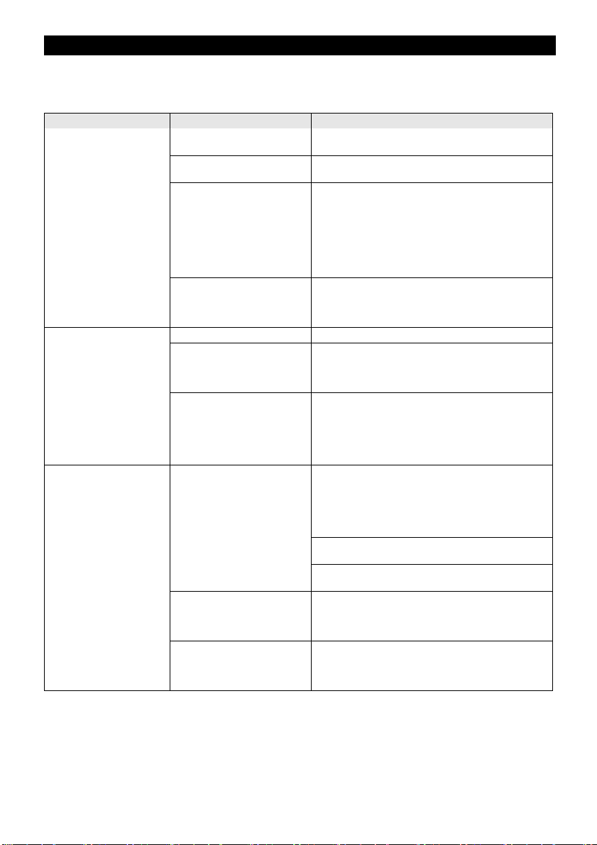
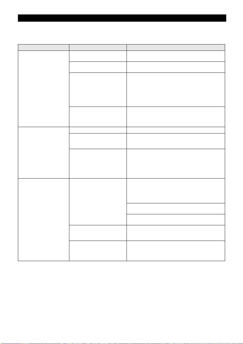
Hilfe bei Störungen
몇 Achtung
Um Gefährdungen zu vermeiden, dürfen Reparaturen und der Einbau von Ersatzteilen nur vom autorisierten Kundendienst durchgeführt werden.
Vor allen Arbeiten am Gerät, Gerät ausschalten und Netzstecker ziehen.
Störung Ursache Behebung
Pumpe läuft aber fördert
nicht
Pumpe läuft nicht an oder
bleibt während des Betriebs
plötzlich stehen
Pumpe stoppt, LED „Fehler
auf Saugseite“ leuchtet auf.
Luft in der Pumpe siehe Kapitel „Vorbereiten“ Abb. A bis D und Kapitel
Ansaugleitung verstopft Pumpe ausschalten, Netzstecker ziehen und Ansaug-
Vorfilter verunreinigt Pumpe ausschalten, Netzstecker ziehen, Pumpe ab-
Ansaugschlauch oder Anschluss-Adapter nicht richtig
oder nicht vollständig eingeschraubt.
Stromversorgung unterbrochen Sicherungen und elektrische Verbindungen prüfen.
Vorfilter verunreinigt Vorfilter und Rückschlagventil entnehmen und unter
Gerät befindet sich im Automatikmodus.
Druck im System > 1,3 bar.
Fehler auf Saugseite, kein
Durchfluss, es wird kein Druck
aufgebaut
Durchfluss sehr gering -> Trockenlaufsicherung hat Pumpe
abgeschaltet.
Fehler Druckseite (Leckage
oder geschlossener Wasserhahn) beim Ansaugen. Pumpe
beendet den Saugmodus nicht.
„Betrieb“
bereich reinigen.
kühlen lassen, Ansaugbereich reinigen, Trockenlauf
verhindern.
Vorfilter und Rückschlagventil entnehmen und unter
fließendem Wasser reinigen, ggf. Schmutzreste am
Boden des Einfüllstutzens durch Einfüllöffnung ausspülen.
Neustart durch Wiedereinschalten der Pumpe.
Vor dem Zusammenbau prüfen, ob die Dichtungen angebracht sind und korrekt sitzen.
Ansaugschlauch und Anschluss-Adapter von Hand
festziehen.
fließendem Wasser reinigen, ggf. Schmutzreste am
Boden des Einfüllstutzens durch Einfüllöffnung ausspülen.
Pumpe schaltet automatisch wieder ein, sobald der
Druck im System unter 1,3 bar sinkt.
Im Automatik-Betrieb läuft das Gerät auch nach Ausund Wiedereinschalten nicht an, wenn mehr als 1,3 bar
Innendruck herrschen, also wenn auf die Pumpe eine
Wassersäule von mehr als 13 Meter wirkt.
Pumpe ausschalten und Netzstecker ziehen.
Vorfilter und Rückschlagventil entnehmen und unter
fließendem Wasser reinigen, ggf. Schmutzreste am
Boden des Einfüllstutzens durch Einfüllöffnung ausspülen.
Neustart durch Wiedereinschalten der Pumpe.
Anschlüsse auf Saugseite auf Leckagen prüfen.
Neustart durch Wiedereinschalten der Pumpe.
Überprüfen, ob ausreichend Wasser im Ansaugbehälter (z. B. Zisterne) vorhanden ist.
Überprüfen, ob ausreichend Wasser im Ansaugbehälter (z. B. Zisterne) vorhanden ist.
Der Durchfluss ist zu gering. Wasserhahn weiter öffnen.
Wasserhahn öffnen.
System auf Leckage prüfen. Kann die Leckage nicht
beseitigt werden, Druckausgleichsbehälter einbauen.
8 DE
– 4
Page 9
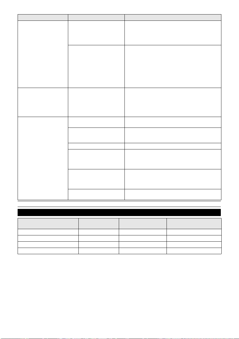
Störung Ursache Behebung
Automatikbetrieb:
Pumpe stoppt, LED „Fehler
auf Druckseite“ leuchtet auf.
Dauerbetrieb:
Pumpe stoppt, LED „Fehler
auf Druckseite“ leuchtet auf.
Förderleistung nimmt ab
oder ist zu gering
Fehler auf Druckseite, Pumpe
schaltet aufgrund von Leckagen häufig ein und aus.
Fehler auf Druckseite.
Druck ist nach dem Abschalten
der Pumpe zu gering, Gerät
startet sofort wieder neu und
schaltet dadurch häufig ein und
aus.
Gerät arbeitet min. vier Minuten, obwohl druckseitiger Ausgang (z. B. Wasserhahn) geschlossen ist.
Überhitzungsschutz schaltet
das Gerät ab.
Ansaugleitung verstopft Pumpe ausschalten, Netzstecker ziehen und Ansaug-
Druckseite auf Leckagen überprüfen und beseitigen
(tropfender Wasserhahn).
Neustart durch Wiedereinschalten der Pumpe.
System auf Leckage prüfen. Kann die Leckage nicht
beseitigt werden, Druckausgleichsbehälter einbauen.
Auf der Druckseite ist kein ausreichendes elastisches
Volumen vorhanden.
Bei Gartenanwendung einen Gartenschlauch mit einer
Mindestlänge von 5 m bei 3/4" Durchmesser bzw. 15 m
bei 1/2" Durchmesser verwenden.
Bei Festinstallation einen Druckausgleichsschlauch
oder Druckausgleichsbehälter druckseitig zwischen
Pumpe und Verrohrung einbauen.
Neustart durch Wiedereinschalten der Pumpe.
Netzstecker ziehen.
Gerät drucklos machen durch Öffnen der druckseitig
angeschlossenen Wasserentnahme.
Neustart durch Wiedereinschalten der Pumpe.
bereich reinigen.
Vorfilter verunreinigt Vorfilter und Rückschlagventil entnehmen und unter
fließendem Wasser reinigen, ggf. Schmutzreste am
Boden des Einfüllstutzens durch Einfüllöffnung aus-
spülen.
Undichtigkeit auf Saugseite Kontrolle der gesamten Ansaugseite auf Dichtigkeit.
Förderleistung der Pumpe ist
abhängig von der Förderhöhe
und der angeschlossenen Peripherie
Querschnitt auf Druckseite verengt, z. B. durch nicht vollständig geöffnetes Ventil/Kugel-
Max. Förderhöhe beachten, siehe technische Daten,
ggf. anderen Schlauchdurchmesser oder andere
Schlauchlänge wählen.
Ventil/Kugelhahn vollständig öffnen.
hahn.
Schlauch auf Druckseite ge-
knickt.
Knickstellen im Schlauch beseitigen.
Bei Fragen oder Störungen hilft Ihnen unsere Kärcher-Niederlassung gerne weiter. Adresse siehe Rückseite.
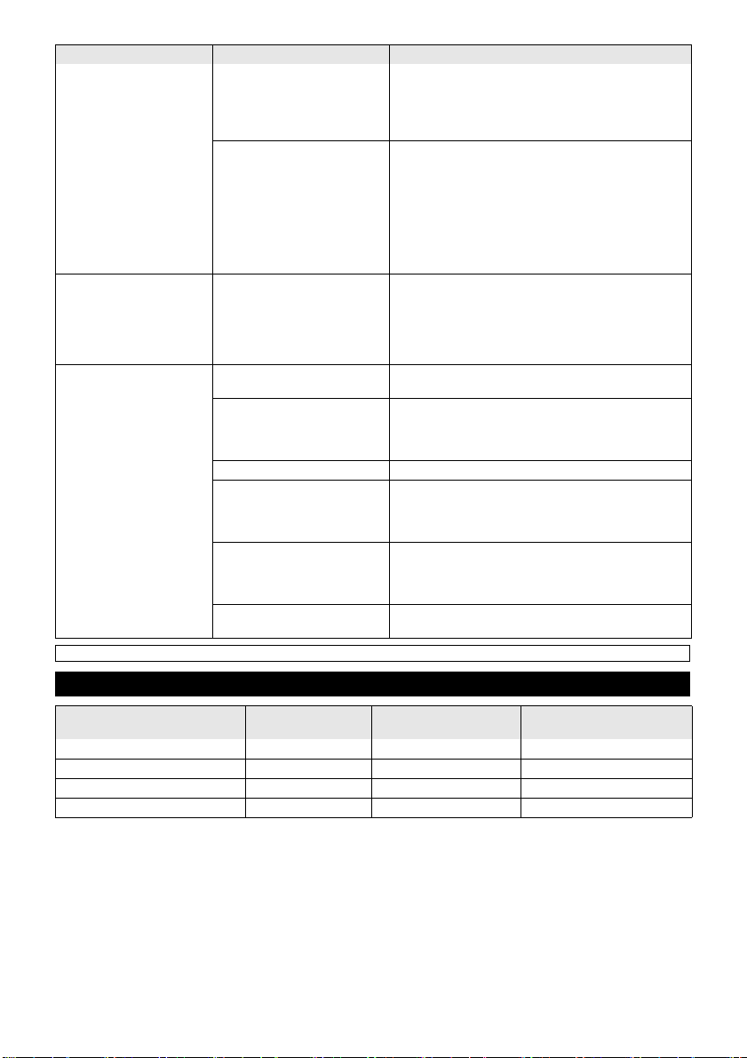
Bewässerung Hausversorgung Bewässerung & Hausversor-
BP 3 Home & Garden 500 m
BP 4 Home & Garden 800 m
BP 5 Home & Garden 1000 m
BP 7 Home & Garden 1200 m
Anwendungshinweise
2
max. 8 Personen max. 300 m2 + 4 Personen max.
2
max. 10 Personen max. 600 m2 + 4 Personen max.
2
max. 12 Personen max. 800 m2 + 4 Personen max.
2
max. 12 Personen max. 900 m2 + 4 Personen max.
gung
– 5
9DE
Page 10
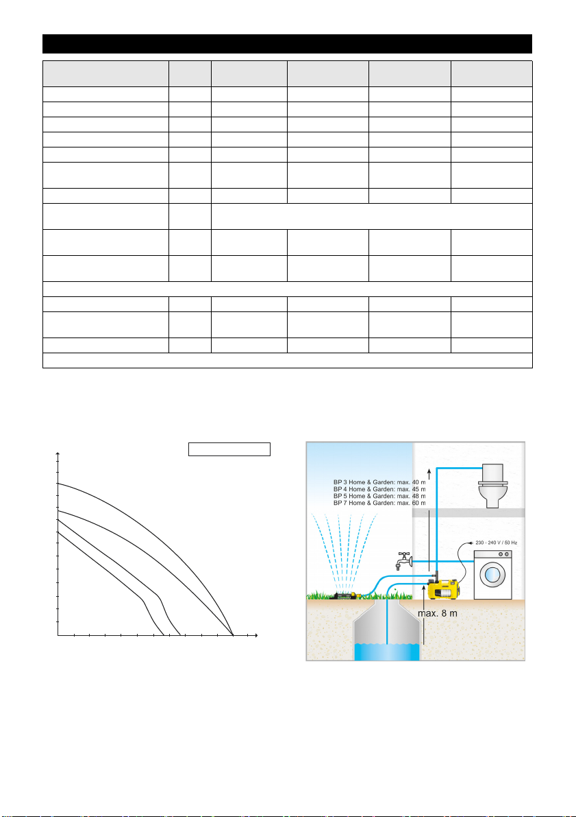
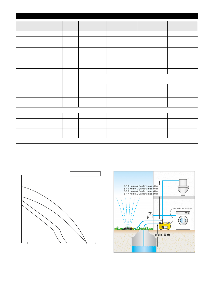
Technische Daten
I/h
m
1000 2000
3000 4000
5000 6000
40
70
60
50
30
20
10
10m = 0,1MPa (1bar)
BP 3 Home & GardenBP 3 Home & Garden
BP 4 Home & GardenBP 4 Home & Garden
BP 7 Home & GardenBP 7 Home & Garden
BP 5 Home & GardenBP 5 Home & Garden
BP 3 Home &
Garden
Spannung V 230 - 240 230 - 240 230 - 240 230 - 240
Frequenz Hz 50 50 50 50
Leistung P
nenn
W 800 950 1000 1200
Max. Fördermenge l/h 3300 3800 6000 6000
Max. Ansaughöhe m 8 8 8 8
Max. Druck MPa
(bar)
0,40
(4,0)
Max. Förderhöhe m 40 45 48 60
Max. Wiedereinschaltdruck
im Automaticmodus
Max. Korngröße der förder-
MPa
(bar)
mm 1 1 1 1
baren Schmutzpartikel
Pumpentyp Jet Jet Multistage 4-stu-
Ermittelte Werte gemäß EN ISO 20361
Schalldruckpegel L
pA
Schallleistungspegel L
garantiert
dB(A) 61 63 61 61
dB(A) 76 78 77 76
WA,
Gewicht (ohne Zubehör) kg 10,3 10,6 12,5 13,0
LED Klasse 1 nach EN 60825-1
Technische Änderungen vorbehalten!
BP 4 Home &
Garden
0,45
(4,5)
BP 5 Home &
Garden
0,48
(4,8)
0,13
(1,3)
BP 7 Home &
Garden
0,60
(6,0)
fig
Multistage 5-stu-
fig
Die mögliche Fördermenge ist umso größer:
- je geringer die Ansaug- und Förderhöhen sind.
- je größer die Durchmesser der verwendeten Schläuche sind.
- je kürzer die verwendeten Schläuche sind.
- je weniger Druckverlust das angeschlossene Zubehör verursacht.
10 DE
* Im Automatikmodus max. 13m
– 6
Page 11

EU-Konformitätserklärung
Chief Executive Officer
Head of Approbation
Hiermit erklären wir, dass die nachfolgend bezeichnete
Maschine aufgrund ihrer Konzipierung und Bauart sowie in der von uns in Verkehr gebrachten Ausführung
den einschlägigen grundlegenden Sicherheits- und Gesundheitsanforderungen der EU-Richtlinien entspricht.
Bei einer nicht mit uns abgestimmten Änderung der Maschine verliert diese Erklärung ihre Gültigkeit.
Produkt: Pumpe
Typ: 1.645-xxx
Einschlägige EU-Richtlinien
2014/35/EU
2014/30/EU
2000/14/EG
2011/65/EU
Angewandte harmonisierte Normen
EN 60335–1
EN 60335–2–41
EN 62233: 2008
EN 55014–1: 2006+A1: 2009+A2: 2011
EN 55014–2: 2015
EN 61000–3–2: 2014
EN 61000–3–3: 2013
EN 50581
Angewandtes Konformitätsbewertungsverfahren
2000/14/EG: Anhang V
Schallleistungspegel dB(A)
BP2 G
Gemessen: 69
Garantiert: 72
BP3 G, BP3 G Set +,BP3 H&G
Gemessen: 73
Garantiert: 76
BP4 G
Gemessen: 72
Garantiert: 75
BP4 H&G eco
Gemessen: 75
Garantiert: 78
BP5 H&G
Gemessen: 74
Garantiert: 77
BP7 H&G eco
Gemessen: 73
Garantiert: 76
Die Unterzeichnenden handeln im Auftrag und mit Vollmacht der Geschäftsführung.
Dokumentationsbevollmächtigter:
S. Reiser
Alfred Kärcher GmbH & Co. KG
Alfred-Kärcher-Str. 28 - 40
71364 Winnenden (Germany)
Tel.: +49 7195 14-0
Fax: +49 7195 14-2212
Winnenden, 2016/04/20
– 7
11DE
Page 12
Please read these original operating in-
structions prior to the initial use of your device. Proceed
accordingly. Keep both booklets for future reference or
subsequent owners.
structions and the enclosed safety in-
Contents
General information EN 1
Danger or hazard levels EN 1
Environmental protection EN 1
Connection to the public drinking water
network EN 2
Safety instructions EN 2
Operation EN 2
Maintenance and Care EN 3
Transport EN 3
Storage EN 3
Troubleshooting EN 4
Notes on the operation EN 5
Technical specifications EN 6
EU Declaration of Conformity EN 7
General information
Prerequisites for the appliance's stability
몇 CAUTION
Create stability for the appliance prior to any work on or
with the appliance to prevent accidents or damage.
The stability of the appliance is warranted when it is
placed onto an even surface.
Warranty
The warranty terms published by the relevant sales
company are applicable in each country. We will repair
potential failures of your appliance within the warranty
period free of charge, provided that such failure is
caused by faulty material or defects in manufacturing. In
the event of a warranty claim please contact your dealer
or the nearest authorized Customer Service centre.
Please submit the proof of purchase.
Proper use
This appliance has been designed for use in private
households and is not intended for commercial use.
The manufacturer is not responsible for any damages
that may occur on account of improper use or wrong operations.
The appliance is mainly intended for the use within the
house and garden.
The house & garden pumps switch on and off automatically in case of water demand. Thus, they are suitable
for both the use in the garden and applications inside
the house. They can be perfectly used to supply washing machines or toilet flushing mechanisms inside the
house with water, e.g. in combination with a cistern.
Moreover, the constant operating pressure of the
pumps also ensures reliable garden irrigation.
몇 CAUTION
Risk of damage! The pump is not suitable for the intensification of the present line pressure.
Approved fluids
Used water
Well water
Water source
Rain water
Water from swimming pool (provided the dosing of
additives is proper)
몇 CAUTION
Water that has been delivered with this appliance is
no drinking water!
몇 WARNING
Caustic, slightly inflammable and other explosive substances (such as petrol, petroleum, diluted nitrogen),
greases, oils, salt water and waste water from toilets as
well as sludgy water that has a slower flow capacity than
water, must not be transported with this pump.
The device is equipped with a dry run fuse and is not
suitable for a continuous operation (e.g. lifting system,
fountain pump).
The temperature of the delivered liquid must not exceed
35 °C
Danger or hazard levels
DANGER
Immediate danger that can cause severe injury or even
death.
몇 WARNING
Possible hazardous situation that could lead to severe
injury or even death.
몇 CAUTION
Pointer to a possibly dangerous situation, which can
lead to minor injuries.
ATTENTION
Pointer to a possibly dangerous situation, which can
lead to property damage.
Environmental protection
Notes about the ingredients (REACH)
You will find current information about the ingredients
at:
www.kaercher.com/REACH
The packaging material can be recycled. Please
arrange for the environmentally appropriate disposal of the packaging.
Electrical and electronic devices often contain
components which could potentially pose a danger to human health and the environment if handled or disposed of incorrectly. However, these
components are necessary for the proper operation of the device. Devices marked with this symbol must not be disposed of with regular household rubbish.
Old appliances contain valuable recyclable materials that should be recycled properly. Batteries
and accumulators contain substances that must
not enter the environment. Please dispose of old
devices and batteries or accumulators in an environmentally friendly way.
12 EN
– 1
Page 13
Connection to the public drinking water
network
Please observe the requirements of EN 1717 when connecting this product to the drinking water network and
contact your sanitation specialists if you have any questions.
Safety instructions
Please follow the safety instructions before starting up
the pump!
Operation
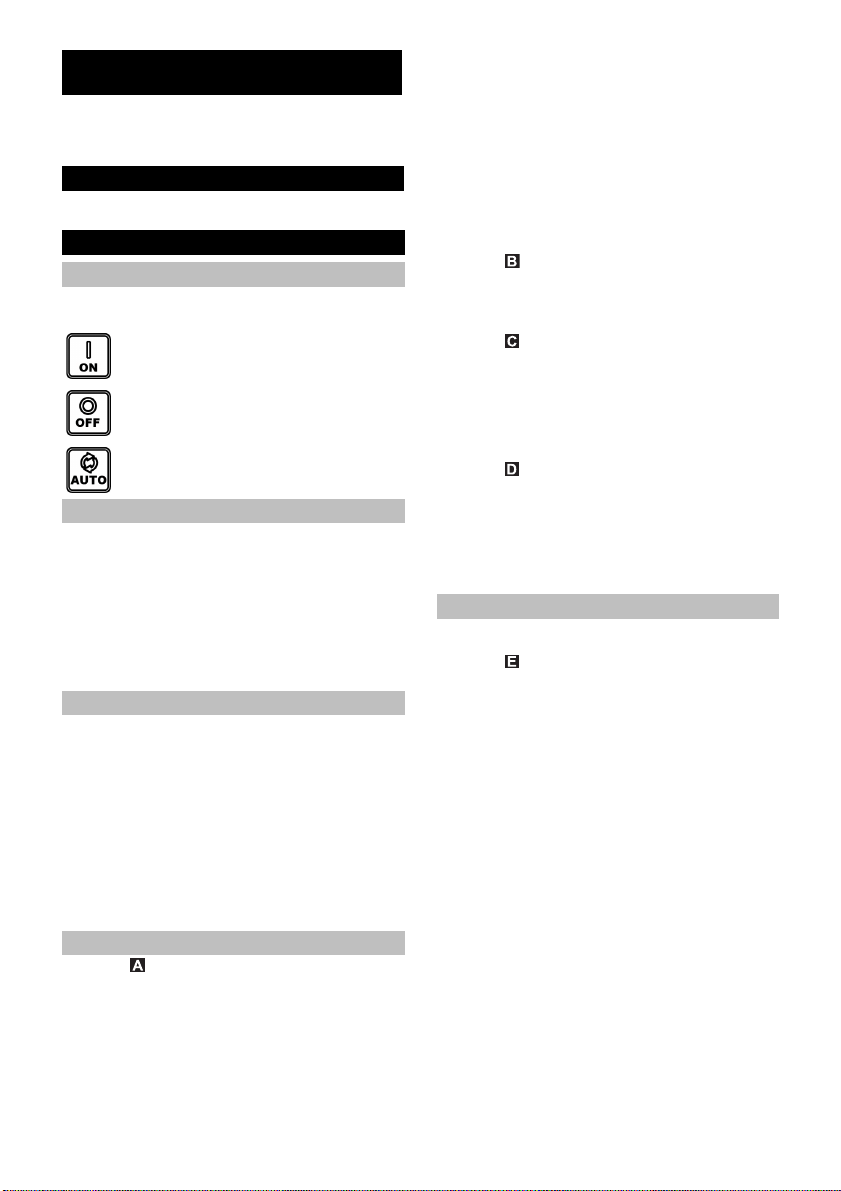
Settings
With the ON/OFF switch the following three operating
conditions can be switched:
Switch position I/On
Continuous operation
Switch position 0/Off
Off
Switch position Auto
Automatic mode
System operation
In the automatic mode the house & garden pumps automatically maintain the pressure in the system. If the
pressure falls below approx. 0.13 MPa (1.3 bar), the
pump is started. The pump is running as long as the flow
rate
> is approx. 60 l/h. If the withdrawal of water is completed, the pump goes into the stand-by mode after a short
stopping time. The system is now under pressure. In
case of water withdrawal and the resulting loss of pressure the pump starts again.
Description of the Appliance
1 Connection adapter for pumps G1
2 Connection G1 (33.3 mm) suction pipe (inlet)
3 Filling nozzle
4 Pre-filter and integrated check valve
5 Cover
6 2-way connection adapter for pumps G1
7 Connection G1 (33.3 mm) delivery line (output)
8 ON/OFF switch
9 Cable storage and mains cable with plug
10 Cable clip
11 Error display
A Error on suction side
B Error on delivery side
Preparing the Appliance
Illustration
Screw the connection adapter in the suction con-
nection of the pump (inlet).
Tighten manually.
Connect the vacuum-proof suction hose.
Note
In order to reduce the time required for suction to start
again, use a suction hose that is equipped with a backflow stop. This prevents the emptying of the suction
hose after use (see accessories).
Do not install the backflow stop directly on the pump
(suction or delivery side).
If sandy water is to be delivered, we strongly recommend the use of an additional pre-filter (see optional accessories). Please install this filter on the suction side of
the pump, between the suction hose and the pump.
Please use original Kärcher suction pipes, filter components and hose connections. When using components
of other manufacturers, malfunctions during drawing in
the delivery fluid may arise, especially when using bayonet connection systems.
Do not use quick couplings, but screwed connections
with domestic or permanent installations.
Illustration
Screw the connection adapter in the delivery con-
nection of the pump (outlet).
Tighten manually.
Connect delivery line.
Illustration
The 2-way adapter allows the simultaneous operation of
two appliances (e.g. washing machine or sprinkler). It
can be mounted in a way that either both outlets are
used at the side or one outlet at the side and one outlet
at the top. If only one outlet is used, the outlet that is not
required can be closed by means of the accompanying
closing cap.
Illustration
Unscrew the lid of the filler neck and fill in water up
to the brim.
Manually screw the lid all the way to the stop on the
filler neck.
Open existing shutoff valves in the pressure pipe.
Note
Even the smallest of leakage leads to malfunctioning.
Permanent installation
With a permanent installation the pump can be screwed
onto a suitable surface.
Illustration
Pull out and turn the rubber feet on both sides of the
casing.
Reinsert the rubber feed into the casing.
Use suitable screws to screw it onto a level surface.
In case of a permanent installation the installation of a
flexible component such as a flexible pressure compensating hose (see optional accessories) on the pressure
side is recommended. This has the following benefits:
More flexibility during set-up and installation.
Noise reduction, as no vibrations are transferred to
pipes in the domestic water system.
In case of small leaks, the pump does not switch as
often.
Note
To facilitate subsequent emptying and pressure release
of the system, we recommend the installation of a stopcock between pump and pressure line.
(not included in delivery)
By closing the shut-off valve when emptying the pump
you can prevent water from escaping from the pressure
line.
If there are increased drops in pressure due to leaks in
the house system (pump regularly switches on without
dispensing water), install a pressure equalization container.
– 2
13EN
Page 14
Operation
Insert the mains plug into the socket.
Switch on the appliance using the ON/OFF switch.
Optimum convenience with operation in the auto-
matic mode.
Illustration
In order to reduce the suction time, lift the delivery
hose approx. 1m.
Wait till the pump sucks in and transports water uni-
formly
Note
The ON/OFF switch can also be conveniently operated
with your foot.
Note
In the automatic mode the pump switches off at a flow
rate of < 60 l/h.
몇 Caution
Lacking water supply is recognised by the appliance. If
no water is drawn and delivered within 4 minutes during
start-up in the manual mode or within 3 minute in the automatic mode, the pump shuts off. The LED "Error on
the suction side" is illuminated on the display.
Finish operation
Switch off the appliance using the On/Off switch.
Disconnect the main plug from the socket.
Maintenance and Care
DANGER
Turn off the appliance and remove the mains plug prior
to any care and maintenance works.
Care
Open the connected shutoff valves to relief pressure
and reclose them. The system is free of pressure.
Rinse the pump after every use if you use to trans-
port water with additives.
Check pre-filter regularly for dirt. If it is visibly dirty, proceed as follows:
Illustration
Unscrew the lid of the filling nozzle.
Remove the entire prefilter.
Separate the check valve from the prefilter.
Carefully clean the prefilter and the check valve un-
der flowing water.
If necessary, rinse the residual dirt from the pump.
Check the check valve for ease of movement.
If sluggish, lightly grease the check valve seals us-
ing grease (6.288-143.0) available from Kärcher
Service.
Do not use mineral lubricants or oils.
Connect the prefilter and check filter to each other
again.
Illustration
When inserting the pre-filter (with check valve) in
the filler neck, mind the correct installation posi-
tion (notch). It must be possible to insert the pre-fil-
ter easily and without exertion of force.
몇 Caution
Only use grease that is free from mineral oil for seals.
Maintenance
The appliance is maintenance free.
Transport
몇 CAUTION
In order to prevent accidents or injuries, mind the weight
of the appliance during transport (see technical data).
When transporting by hand
Lift appliance by the carrying handle and carry it.
몇 CAUTION
Tripping hazard due to loose cables!
Coil cable onto the cable holder and secure it by
means of a cable clip.
When transporting in vehicles
Secure the appliance against shifting and tipping
over.
Storage
몇 CAUTION
In order to prevent accidents or injuries, mind the weight
of the appliance when choosing the storage location
(see technical data).
Storing the Appliance
Depressurise the appliance by opening the water
outlet connected on the delivery side (e.g. opening
the tap).
Drain hoses.
Remove suction pipe and delivery line.
Illustration
Unscrew the lid of the filling nozzle.
Remove the pre-filter and the built in backflow
valve and clean them under flowing water.
Empty the pump over the filler neck by turning it
around.
Store the appliance in a frost free area.
14 EN
– 3
Page 15
Troubleshooting
몇 Caution
To avoid risks, all repairs and replacement of spare parts may only be carried out by the authorised customer service
personnel.
Prior to all work on the appliance, switch off the appliance and pull the power plug.
Fault Cause Remedy
Pump runs but does not
transport
Pump does not run or suddenly comes to a standstill
during operations
Pump stops, LED "Error on
suction side" is illuminated.
Air in the pump see Chapter "Preparation" Fig. A to D and Chapter
Suction pipe blocked Switch off the pump, pull the mains plug and clean the
Pre-filter is dirty Switch off the pump, pull the mains plug, allow the
Suction hose or connection
adapter not screwed in correctly or completely.
Power supply interrupted Check fuses and electrical connections
Pre-filter is dirty Remove the pre-filter and the check valve and clean it
The appliance is in the automatic mode.
Pressure in the system >
1.3 bar.
Failure on the suction side,
pressure cannot build up
Flow rate very low -> the dry
run protection has switched off
the pump.
Fault delivery side (leakage or
closed tap) during suction.
Pump does not end the suction
mode.
"Operation"
intake area.
pump to cool down, clean intake area, prevent dry running.
Remove the pre-filter and the check valve and clean it
under running water, flush dirt residues from the bottom of the filler neck through the filler hole if necessary.
Restart by switching the pump back on.
Check whether all seals have been installed and are
seated correctly prior to assembly.
Manually tighten the suction hose and the connection
adapter.
under running water, flush dirt residues from the bottom of the filler neck through the filler hole if necessary.
The pump automatically switches back on as soon as
the pressure in the system falls below 1.3 bar.
In automatic mode the device does not start up even
after switching it off and back on if there is an internal
pressure of more than 1.3 bar, thus, when a water column of more than 13 metres affects the pump.
Switch off the pump and pull the power plug.
Remove the pre-filter and the check valve and clean it
under running water, flush dirt residues from the bottom of the filler neck through the filler hole if necessary.
Restart by switching the pump back on.
Check connections on the suction side for leakage.
Restart by switching the pump back on.
Check if there is sufficient water in the suction container (e.g. cistern).
Check if there is sufficient water in the suction container (e.g. cistern).
The flow is insufficient. Open tap more.
Open tap.
Check system for leakage. If the leakage cannot be
eliminated, install pressure equalization container.
– 4
15EN
Page 16
Fault Cause Remedy
Automatic mode:
Pump stops, LED "Error on
delivery side" is illuminated.
Continuous operation:
Pump stops, LED "Error on
delivery side" is illuminated.
Pump transports is reducing or transported quantity
is too low
Failure in the pressure line, the
pump frequently switches on
and off as a result of leakage.
Error on delivery side.
The pressure is too low after
shutdown of the pump, the appliance starts again immediately and thus switches on and
off frequently.
The appliance works for at
least four minutes, although
the outlet on the delivery side
(e.g. tap) is closed.
Overheating protection switches off the appliance.
Suction pipe blocked Switch off the pump, pull the mains plug and clean the
Check and correct the pressure line for leakages (dripping water tap).
Restart by switching the pump back on.
Check system for leakage. If the leakage cannot be
eliminated, install pressure equalization container.
There is no sufficient elastic volume available on the
delivery side.
Use a garden hose with a minimum length of 5 m at a
diameter of 3/4" or 15 m at a diameter of 1/2" for garden applications.
With permanent installations, install a pressure equalization hose or pressure equalization container on the
delivery side between the pump and the piping.
Restart by switching the pump back on.
Pull out the mains plug.
Depressurise the appliance by opening the water outlet connected on the delivery side.
Restart by switching the pump back on.
intake area.
Pre-filter is dirty Remove the pre-filter and the check valve and clean it
under running water, flush dirt residues from the bot-
tom of the filler neck through the filler hole if necessary.
Suction side is leaky Check the entire suction side for leaks
The quantity transported by the
pump depends on the transport
height and the connected pe-
Keep max. flow height, see technical data. If neces-
sary, select a different hose diameter or hose length.
riphery
Cross section on the delivery
side constricted, e.g. due to
valve/ball valve that is not completely opened.
Hose on the delivery side is
kinked.
Completely open the valve/ball valve.
Remove kinks from the hose.
Our Kärcher branch will be pleased to help you further in the case of questions or faults. See address on the reverse.
Notes on the operation
Irrigation Household water supply Irrigation & household wa-
BP 3 Home & Garden 500 m
BP 4 Home & Garden 800 m
BP 5 Home & Garden 1000 m
BP 7 Home & Garden 1200 m
2
max. 8 persons max. 300 m2 + 4 persons max.
2
max. 10 persons max. 600 m2 + 4 persons max.
2
max. 12 persons max. 800 m2 + 4 persons max.
2
max. 12 persons max. 900 m2 + 4 persons max.
ter supply
16 EN
– 5
Page 17
Technical specifications
I/h
m
1000 2000
3000 4000
5000 6000
40
70
60
50
30
20
10
10m = 0,1MPa (1bar)
BP 3 Home & GardenBP 3 Home & Garden
BP 4 Home & GardenBP 4 Home & Garden
BP 7 Home & GardenBP 7 Home & Garden
BP 5 Home & GardenBP 5 Home & Garden
BP 3 Home &
Garden
Voltage V 230 - 240 230 - 240 230 - 240 230 - 240
Frequency Hz 50 50 50 50
Output P
nom
W 800 950 1000 1200
Max. flow rate l/h 3300 3800 6000 6000
Max. Suction height m 8 8 8 8
Max. pressure MPa
(bar)
0,40
(4,0)
Max. flow height m 40 45 48 60
Max. switch on pressure in
the automatic mode
Max. grain size of the dirt
particles that can be transported
MPa
(bar)
mm 1 1 1 1
Pump type Jet Jet Multi-stage 4-
Values determined as per EN ISO 20361
Sound pressure level L
Sound power level L
anteed
Weight (without accesso-
dB(A) 61 63 61 61
pA
guar-
dB(A) 76 78 77 76
WA,
kg 10,3 10,6 12,5 13,0
ries)
LED class 1 as per EN 60825-1
Subject to technical modifications!
BP 4 Home &
Garden
0,45
(4,5)
BP 5 Home &
Garden
0,48
(4,8)
0,13
(1,3)
stage
BP 7 Home &
Garden
0,60
(6,0)
Multi-stage 5-
stage
The possible delivery rate is even larger:
- the smaller the suction and delivery heights are.
- the larger the diameter of the hoses used are.
- the shorter the hoses used are.
- the less loss of pressure is caused by the connected accessories.
* In the automatic mode max. 13 m
– 6
17EN
Page 18

EU Declaration of Conformity
Chief Executive Officer
Head of Approbation
We hereby declare that the machine described below
complies with the relevant basic safety and health requirements of the EU Directives, both in its basic design
and construction as well as in the version put into circulation by us. This declaration shall cease to be valid if
the machine is modified without our prior approval.
Product: Pump
Type: 1.645-xxx
Relevant EU Directives
2014/35/EU
2014/30/EU
2000/14/EC
2011/65/EU
Applied harmonized standards
EN 60335–1
EN 60335–2–41
EN 62233: 2008
EN 55014–1: 2006+A1: 2009+A2: 2011
EN 55014–2: 2015
EN 61000–3–2: 2014
EN 61000–3–3: 2013
EN 50581
Applied conformity evaluation method
2000/14/EC: Appendix V
Sound power level dB(A)
BP2 G
Measured: 69
Guaranteed: 72
BP3 G, BP3 G Set +,BP3 H&G
Measured: 73
Guaranteed: 76
BP4 G
Measured: 72
Guaranteed: 75
BP4 H&G eco
Measured: 75
Guaranteed: 78
BP5 H&G
Measured: 74
Guaranteed: 77
BP7 H&G eco
Measured: 73
Guaranteed: 76
The undersigned act on behalf and under the power of
attorney of the company management.
Authorised Documentation Representative
S. Reiser
Alfred Kärcher GmbH Co. KG
Alfred-Kärcher-Str. 28 - 40
71364 Winnenden (Germany)
Phone: +49 7195 14-0
Fax: +49 7195 14-2212
Winnenden, 2016/04/20
18 EN
– 7
Page 19
Avant la première utilisation de votre ap-
tructions original et les consignes de sécurité qu'il
contient. Respecter l'ensemble de ces instructions.
Conservez les deux livrets pour une utilisation ultérieure
ou pour le futur propriétaire.
pareil, lire attentivement ce manuel d'ins-
Table des matières
Consignes générales FR 1
Niveaux de danger FR 1
Protection de l’environnement FR 1
Raccordement au réseau d'eau potable
public FR 2
Consignes de sécurité FR 2
Utilisation FR 2
Entretien, maintenance FR 3
Transport FR 3
Stockage FR 3
Assistance en cas de panne FR 4
Instructions pour l’utilisation FR 5
Caractéristiques techniques FR 6
Déclaration UE de conformité FR 7
Consignes générales
Conditions pour la stabilité
몇 PRÉCAUTION
Avant d'effectuer toute opération avec ou sur l'appareil,
en assurer la stabilité afin d'éviter tout accident ou tout
endommagement dû à une chute de l'appareil.
La stabilité de l'appareil est assurée lorsqu'il peut être
posé sur une surface plane.
Garantie
Dans chaque pays, les conditions de garantie en vigueur sont celles publiées par notre société de distribution responsable. Les éventuelles pannes sur l’appareil
sont réparées gratuitement dans le délai de validité de
la garantie, dans la mesure où celles-ci relèvent d'un
défaut matériel ou d'un vice de fabrication. En cas de recours en garantie, adressez-vous à votre revendeur ou
au service après-vente agréé le plus proche munis de
votre preuve d'achat.
Utilisation conforme
Cet appareil ne doit être utilisé que pour un usage domestique.
Le fabricant décline tout responsabilité en cas de dommages issus d'une utilisation non conforme ou incorrecte de l'appareil.
L'appareil est surtout destiné à une utilisation dans la
maison et le jardin.
Les pompes de jardin sont automatiquement activées et
désactivées en cas de besoin en eau. Elles conviennent
ainsi aussi bien aux utilisations dans le jardin qu'à celles
dans la maison. Elles peuvent être parfaitement employées pour alimenter des lave-linge ou des chasses
d'eau dans la maison, par exemple en relation avec une
citerne. En plus de cela, la pression de service
constante des pompes garantit également un arrosage
fiable du jardin.
몇 PRÉCAUTION
Risque d'endommagement ! La pompe n'est pas appropriée pour un renforcement de la pression de conduite
existante.
Fluides transportés autorisés
Eau d'usage
Eau de puits
Eau de source
Eau de pluie
Eau de piscine (dosage de l'additif selon les dispo-
sitions imposé au préalable)
몇 PRÉCAUTION
L'eau qui est transportée dans cet appareil n'est
pas de l'eau potable !
몇 AVERTISSEMENT
Il est interdit de transporter des substances corrosives,
facilement inflammables ou explosives (par ex. essence, pétrole, diluant pour laque cellulosique),
graisses, huiles, eau salée et eaux usées en provenance des toilettes et pour les eaux boueuses dont la
fluidité est inférieure à celle de l'eau.
L'appareil est équipé d'une protection contre la marche
à sec et n'est pas approprié pour un fonctionnement en
continu ininterrompu (par ex. installation de levage,
pompe de fontaine).
La température du liquide transporté ne doit pas dépasser 35°C.
Niveaux de danger
DANGER
Pour un danger immédiat qui peut avoir pour conséquence la mort ou des blessures corporelles graves.
몇 AVERTISSEMENT
Pour une situation potentiellement dangereuse qui peut
avoir pour conséquence des blessures corporelles
graves ou la mort.
몇 PRÉCAUTION
Remarque relative à une situation potentiellement dangereuse pouvant entraîner des blessures légères.
ATTENTION
Remarque relative à une situation éventuellement dangereuse pouvant entraîner des dommages matériels.
Protection de l’environnement
Instructions relatives aux ingrédients (REACH)
Les informations actuelles relatives aux ingrédients se
trouvent sous :
www.kaercher.com/REACH
Les matériels d'emballage sont recyclables. Éliminez l'emballage d'une manière respectueuse
de l'environnement.
Les appareils électriques et électroniques renferment souvent des composants qui peuvent représenter un danger potentiel pour l'intégrité physique et l'environnement s'ils sont mal utilisés ou
éliminés. Ces composants sont pourtant nécessaires au bon fonctionnement de l'appareil. Les
appareils qui présentent ce symbole ne doivent
pas être jetés avec les déchets ménagers.
Les appareils ancien modèle contiennent des
matériaux précieux recyclables qui doivent être
amenés à un système de recyclage. Les batteries
et les accumulateurs contiennent des substances
ne devant pas être tout simplement jetées. Veuillez éliminer les anciens appareils ainsi que les
batteries ou les accumulateurs d'une manière
respectueuse de l'environnement.
– 1
19FR
Page 20
Raccordement au réseau d'eau potable
public
Lors du raccordement de ce produit au réseau d'eau potable, respecter les exigences de la norme EN 1717 et
s’adresser à un spécialiste sanitaire pour toute question.
Consignes de sécurité
Avant la mise en service de la pompe, respecter les
consignes de sécurité fournies !
Utilisation
Réglages
Une commutation est effectuée entre les trois états de
fonctionnement avec l'interrupteur Marche/Arrêt :
position de l'interrupteur I/On
Marche continue :
position de l'interrupteur 0/Off
Arrêt
position de l'interrupteur Auto
Fonctionnement automatique
Mode de fonctionnement
En mode automatique, les pompes de jardin maintiennent automatiquement la pression dans le système.
Si la pression tombe en dessous de 0,13 MPa environ
(1,3 bar), la pompe démarre. La pompe tourne tant que
le débit s'élève à env.
> env. 60 l/h. Si le prélèvement d'eau est terminé, la
pompe passe après une courte temporisation en état de
veille. Le système est maintenant sous pression. En cas
de prélèvement d'eau, la pompe redémarre, en raison
de la perte de pression qui en résulte.
Description de l’appareil
1 Adaptateur de raccordement pour pompes G1
2 Raccordement G1 (33,3 mm) conduite d'aspiration
(arrivée)
3 Col de remplissage
4 préfiltre et clapet anti-retour intégré
5 Capot
6 Adaptateur de raccordement à 2 voies pour
pompes G1
7 Raccordement G1 (33,3 mm) conduite de pression
(sortie)
8 Interrupteur Marche/Arrêt
9 rangement de câble et câble d'alimentation avec
fiche
10 clip de câble
11 Affichage de défauts
A défauts sur le côté aspiration
B défauts sur le côté pression
Préparation
Illustration
Visser l'adaptateur de raccordement dans le
connecteur pour flexible d'aspiration de la pompe
(arrivée).
Serrer à la main.
Raccorder le tuyau d'aspiration résistant au vide.
Remarque
Pour réduire la durée de réaspiration, utiliser un tuyau
d'aspiration avec clapet anti-retour. Ceci empêche le vidage du tuyau d'aspiration après utilisation (cf. accessoire).
Ne pas installer le clapet anti-retour directement sur la
pompe (côté aspiration ou pression).
Si de l'eau sableuse doit être transportée, nous recommandons vivement d'utiliser un préfiltre supplémentaire
(voir accessoires spéciaux). Le monter du côté aspiration de la pompe, entre le flexible d'aspiration et la
pompe.
Veuillez utiliser les conduites d'aspiration, composants
de filtre et raccords de flexibles Kärcher d'origine. En
cas d'utilisation de composants d'autres fabricants, il
peut se produire des dysfonctionnements du fluide de
transport, en particulier si des systèmes d'assemblage
à baïonnette sont utilisés.
Pour une installation domestique ou fixe, ne pas utiliser
de coupleurs rapides, mais plutôt des raccords vissés.
Illustration
Visser l'adaptateur de raccordement dans le rac-
cord de pression de la pompe (sortie).
Serrer à la main.
Raccorder la conduite de pression.
Illustration
L'adaptateur à 2 voies permet le fonctionnement simultané de deux appareils (par ex. lave-linge ou sprinkler).
Il peut être monté de telle sorte que soit deux sorties sur
le côté, soit une sortie sur le côté et une sortie sur le
dessus soient utilisées. Lors de l'utilisation d'une seule
sortie, la sortie non nécessaire peut être fermée avec le
capuchon de fermeture fourni.
Illustration
Dévisser le couvercle au niveau de la tubulure de
remplissage et remplir d'eau jusqu'au bord.
Visser le couvercle à la main jusqu'en butée sur la
tubulure de remplissage.
Ouvrir les vannes d'arrêt présentes dans la
conduite de pression.
Remarque
Les fuites les plus minimes entraînent un des dysfonctionnements.
installation fixe
Dans une installation fixe, la pompe peut être fixée fermement sur une surface adaptée.
Illustration
Extraire et tourner les pieds en caoutchouc sur les
deux côtés du boîtier.
Remettre en place les pieds en caoutchouc dans le
boîtier.
Visser fermement avec les vis adaptées sur une
surface plane.
De plus, il est recommandé pour une installation fixe de
monter un composant flexible, comme par ex. un
flexible de compensation de pression (cf. accessoire en
option). Ceci présente les avantages suivants :
plus de flexibilité pour l'installation et le montage.
Réduction des bruits, comme aucune coulisse
n'est transférée dans le système d'eau domestique
au niveau des conduites.
En cas de très petites fuites, la pompe est activée
moins souvent.
20 FR
– 2
Page 21
Remarque
Pour simplifier la purge et la réduction de la pression du
système à l'avenir, nous recommandons de monter un
robinet d'arrêt entre la pompe et la conduite de pression.
(ces éléments ne font pas partie de l’étendue de livraison).
Lors d'une vidange de la pompe, une fermeture du robinet de retenue permet d'empêcher que l'eau ne
s'écoule de la conduite de pression.
En cas de chutes de pression répétées dues à de fuites
dans le système domestique (la pompe s’allume régulièrement sans prélèvement d'eau), installer un réservoir de compensation de pression.
Fonctionnement
Brancher la fiche secteur dans une prise de cou-
rant.
Mettre l'appareil en marche au moyen de l'interrup-
teur MARCHE/ARRET.
Confort optimal lors du fonctionnement en mode
automatique.
Illustration
Pour réduire la durée d'aspiration, soulever le
tuyau de pression d'env. 1 m.
attendre que la pompe aspire et transporte unifor-
mément
Remarque
L'interrupteur Marche/Arrêt peut aussi être activé
confortablement au pied.
Remarque
En mode automatique, la pompe se désactive lorsque
le débit est de < 60 l/min.
몇 Attention
L'appareil identifie l'alimentation d'eau manquante. Si
l'eau n'est pas aspirée ou alimentée dans le cas d'une
mise en service en mode manuel dans un délai de
4 minutes ou en mode automatique dans un délai de 3
minutes, la pompe est mise hors service. La LED "Défaut sur le côté aspiration" s'allume à l'écran.
Fin de l'utilisation
Eteindre l'appareil à l'interrupteur Marche/Arrêt.
Débrancher la fiche secteur.
Entretien, maintenance
DANGER
Avant tout travail d'entretien et de maintenance, mettre
l'appareil hors tension et débrancher la fiche secteur.
Entretien
Ouvrir la vanne d'arrêt raccordée pour la décompression puis la refermer. Le système est hors pression.
pour le transport d'eau avec des additifs, rincer la
pompe à l'eau claire après chaque utilisation.
Contrôler régulièrement l'encrassement du préfiltre.
Procéder de la manière suivante pour les salissures visibles :
Illustration
Dévisser le couvercle du col de remplissage.
Retirer le préfiltre complet.
Séparer le clapet anti-retour du préfiltre.
Nettoyer soigneusement le préfiltre et le clapet
anti-retour à l'eau courante.
Le cas échéant, rincer les restes de salissures de
la pompe.
Vérifier la facilité d'accès du clapet anti-retour.
En cas de grippage, graisser légèrement les joints
du clapet anti-retour avec la graisse (6.288-143.0)
disponible via le service Kärcher.
Ne pas utiliser de graisse ou d'huile minérale.
Raccorder ensemble le préfiltre et le clapet anti-re-
tour.
Illustration
Pour la mise en place du préfiltre (avec clapet anti-
retour), veiller à la bonne position de montage
dans la tubulure de remplissage (évidement). Le
préfiltre doit être mis en place simplement et sans
déploiement de force.
몇 Attention
Pour des joints, utiliser uniquement de la graisse sans
huile minérale.
Entretien
L'appareil ne nécessite aucune maintenance.
Transport
몇 PRÉCAUTION
Afin d'éviter tout accident ou toute blessure lors du
transport, tenir compte du poids de l'appareil (voir les
caractéristiques techniques).
Transport manuel
Soulever l'appareil avec la poignée et le porter.
몇 PRÉCAUTION
risque de trébuchement en raison des câbles
détachés !
Enrouler le câble sur le porte-câble et le fixer avec
le clip de câble.
Transport dans des véhicules
Freiner l'appareil pour l'empêcher de glisser et de
basculer.
Stockage
몇 PRÉCAUTION
Afin d'éviter tout accident ou toute blessure, tenir
compte du poids de l'appareil (voir les caractéristiques
techniques) en choisissant son emplacement pour le
stockage.
Ranger l’appareil
Mettre l'appareil hors pression en ouvrant le prélè-
vement d'eau raccordé côté pression (par
exemple : ouverture du robinet d'eau).
Vider les flexibles.
Retirer la conduite d'aspiration et la conduite de
pression.
Illustration
Dévisser le couvercle du col de remplissage.
Retirer le préfiltre et la soupape anti-retour intégrée
et les nettoyer à l'eau courante.
Vider la pompe par la tubulure de remplissage en
effectuant une rotation.
Conserver l'appareil dans un lieu à l'abri du gel.
– 3
21FR
Page 22

Assistance en cas de panne
몇 Attention
Afin d'éviter tout danger, seul le service après-vente agréé est habilité à effectuer des réparations ou à monter des
pièces de rechanger sur l'appareil.
Avant d'effectuer des travaux sur l'appareil, couper l'interrupteur principal et débrancher la fiche secteur.
Panne Cause Remède
La pompe tourne mais ne
débite pas
La pompe ne tourne pas ou
s'arrête soudainement en
cours de fonctionnement
La pompe s'arrête, la LED
"Erreur sur le côté aspiration" s'allume.
Air dans la pompe cf. chapitre "Préparer" figures A à D et chapitre "Fonc-
Conduite d'aspiration bouchée Couper la pompe, débrancher la fiche secteur et net-
Préfiltre sale Couper la pompe, débrancher la fiche secteur, laisser
flexible d'aspiration ou adaptateur de raccordement non correct ou non complètement vissé.
Alimentation électrique coupée Contrôler les fusibles et les connexions électriques
Préfiltre sale Retirer le préfiltre et le clapet anti-retour et les nettoyer
L'appareil se trouve en mode
automatique.
Pression dans le système >
1,3 bar.
Défaut côté dépression, pas de
débit, la pression n'est pas établie
Débit très faible -> La protection contre la marche à sec a
coupé la pompe.
Erreur côté pression (fuite ou
robinet d'eau fermé) lors de
l'aspiration. La pompe ne met
pas fin au mode aspiration.
tionnement"
toyage la zone d'aspiration.
refroidir la pompe, nettoyer la zone d'aspiration, empêcher qu'elle ne tourne à sec.
Retirer le préfiltre et le clapet anti-retour et les nettoyer
à l'eau courante ; si nécessaire, laver les restes de salissures sur le fond de la tubulure de remplissage en
ouvrant l'orifice de remplissage.
Redémarrage après remise en marche de la pompe.
Avant l'assemblage, vérifier si les joints sont correctement posés.
Serrer le flexible d'aspiration et l'adaptateur de raccordement à la main.
à l'eau courante ; si nécessaire, laver les restes de salissures sur le fond de la tubulure de remplissage en
ouvrant l'orifice de remplissage.
La pompe est automatiquement remise en marche dès
que la pression dans le système tombe sous 1,3 bar.
En mode automatique, l'appareil fonctionne également après une désactivation et une remise en
marche si la pression intérieure est supérieure à
1,3 bar, donc si une colonne d'eau de plus de
13 mètres agit sur la pompe.
Désactiver la pompe et enlever la fiche secteur.
Retirer le préfiltre et le clapet anti-retour et les nettoyer
à l'eau courante ; si nécessaire, laver les restes de salissures sur le fond de la tubulure de remplissage en
ouvrant l'orifice de remplissage.
Redémarrage après remise en marche de la pompe.
Contrôler la présence de fuite côté dépression.
Redémarrage après remise en marche de la pompe.
Vérifier si une quantité suffisante d'eau est présente
dans le réservoir d'aspiration (par ex. citernes).
Vérifier si une quantité suffisante d'eau est présente
dans le réservoir d'aspiration (par ex. citernes).
Le débit est trop faible. Ouvrir davantage le robinet
d'eau.
Ouvrir le robinet d'eau.
Vérifier les fuites éventuelles sur le système. Si la fuite
ne peut pas être éliminée, monter un réservoir de compensation de pression.
22 FR
– 4
Page 23

Panne Cause Remède
Fonctionnement
automatique :
La pompe s'arrête, la LED
"Erreur sur le côté aspiration" s'allume.
Défaut côté pression, la pompe
se met souvent en et hors service en raison de fuites.
Contrôler la présence de fuites côté pression et les éliminer (robinet qui goutte).
Redémarrage après remise en marche de la pompe.
Vérifier les fuites éventuelles sur le système. Si la fuite
ne peut pas être éliminée, monter un réservoir de compensation de pression.
Marche continue :
La pompe s'arrête, la LED
"Erreur sur le côté aspiration" s'allume.
Le dé bit di minu e o u es t t rop
faible
défauts sur le côté pression.
La pression est trop faible
après la désactivation de la
pompe, l'appareil redémarre
aussitôt et se met souvent en
service et hors service.
L'appareil travaille un minimum
de quatre minutes, bien que la
sortie côté pression (par ex. robinet d'eau) soit fermée.
La protection contre les surchauffes désactive l'appareil.
Conduite d'aspiration bouchée Couper la pompe, débrancher la fiche secteur et net-
Du côté pression, l'élasticité des volumes est insuffisante.
Dans la zone du jardin, utiliser un tuyau d'arrosage
d'une longueur minimale de 5 m et d'un diamètre de 3/
4" ou d'une longueur minimale de 15 m et d'un diamètre de 1/2".
Pour une installation fixe, monter un flexible de compensation de pression ou un réservoir de compensation de pression côté pression entre la pompe et la
tuyauterie.
Redémarrage après remise en marche de la pompe.
Retirer la fiche secteur.
Mettre l'appareil hors pression en ouvrant le prélèvement d'eau raccordé côté pression.
Redémarrage après remise en marche de la pompe.
toyage la zone d'aspiration.
Préfiltre sale Retirer le préfiltre et le clapet anti-retour et les nettoyer
à l'eau courante ; si nécessaire, laver les restes de salissures sur le fond de la tubulure de remplissage en
ouvrant l'orifice de remplissage.
Fuite côté aspiration Contrôle de l'étanchéité de l'ensemble du côté aspira-
Le débit de la pompe dépend
de la hauteur manométrique et
des périphériques raccordés
tion.
Respecter la hauteur manométrique max., cf. les ca-
ractéristiques techniques, le cas échéant sélectionner
un autre diamètre de flexible ou une autre longueur de
flexible.
Section réduite sur le côté
pression, par ex. soupape/robinet à boisseau sphérique non
ouvert complètement.
Ouvrir complètement la soupape / le robinet à boisseau sphérique.
Flexible coudé côté pression. Éliminer les coudes dans le flexible.
Notre succursale Kärcher se tient à votre entière disposition pour d'éventuelles questions ou problèmes. L'adresse
figure au dos.
Instructions pour l’utilisation
arrosage alimentation domes-
BP 3 Home & Garden 500 m
BP 4 Home & Garden 800 m
BP 5 Home & Garden 1000 m
BP 7 Home & Garden 1200 m
2
tique
max. 8 personnes maxi 300 m2 + 4 personnes maxi
2
max. 10 personnes maxi 600 m2 + 4 personnes maxi
2
max. 12 personnes maxi 800 m2 + 4 personnes maxi
2
max. 12 personnes maxi 900 m2 + 4 personnes maxi
arrosage & alimentation domestique
– 5
23FR
Page 24

Caractéristiques techniques
I/h
m
1000 2000
3000 4000
5000 6000
40
70
60
50
30
20
10
10m = 0,1MPa (1bar)
BP 3 Home & GardenBP 3 Home & Garden
BP 4 Home & GardenBP 4 Home & Garden
BP 7 Home & GardenBP 7 Home & Garden
BP 5 Home & GardenBP 5 Home & Garden
BP 3 Home &
Garden
Tension V 230 - 240 230 - 240 230 - 240 230 - 240
Fréquence Hz 50 50 50 50
Puissance P
nom
W 800 950 1000 1200
Débit max. l/h 3300 3800 6000 6000
Hauteur max. de l'aspiration m 8 8 8 8
Pression max. MPa
(bar)
0,40
(4,0)
Hauteur manométrique max. m 40 45 48 60
Pression max. de remise en
marche en mode automatique
Granulométrie max. des particules d'impuretés transportables
MPa
(bar)
mm 1 1 1 1
Type de pompe Jet Jet Multistage 4
Valeurs déterminées selon EN ISO 20361
Niveau de pression acoustique L
pA
Niveau de puissance acoustique L
garanti
WA,
dB(A) 61 63 61 61
dB(A) 76 78 77 76
Poids (sans accessoire) kg 10,3 10,6 12,5 13,0
Classe DEL 1 selon EN 60825-1
Sous réserve de modifications techniques !
BP 4 Home &
Garden
0,45
(4,5)
BP 5 Home &
Garden
0,13
(1,3)
étapes
0,48
(4,8)
BP 7 Home &
Garden
0,60
(6,0)
Multistage 5
étapes
La quantité transportée possible augmente :
- plus les hauteurs de transport et d'aspiration sont faibles.
- plus les diamètres des flexibles utilisés sont grands.
- plus les flexibles utilisés sont petits.
- moins les accessoires raccordés ne causent de perte de pression.
24 FR
* En mode automatique max. 13m
– 6
Page 25

Déclaration UE de conformité
Chief Executive Officer
Head of Approbation
Nous certifions par la présente que la machine spécifiée
ci-après répond de par sa conception et son type de
construction ainsi que de par la version que nous avons
mise sur le marché aux prescriptions fondamentales stipulées en matière de sécurité et d’hygiène par les directives européennes en vigueur. Toute modification apportée à la machine sans notre accord rend cette déclaration invalide.
Produit : Pompe
Type : 1.645-xxx
Directives européennes en vigueur :
2014/35/UE
2014/30/UE
2000/14/CE
2011/65/UE
Normes harmonisées appliquées :
EN 60335–1
EN 60335–2–41
EN 62233: 2008
EN 55014–1: 2006+A1: 2009+A2: 2011
EN 55014–2: 2015
EN 61000–3–2: 2014
EN 61000–3–3: 2013
EN 50581
Procédures d'évaluation de la conformité
2000/14/CE: Annexe V
Niveau de puissance acoustique dB(A)
BP2 G
Mesuré: 69
Garanti: 72
BP3 G, BP3 G Set +,BP3 H&G
Mesuré: 73
Garanti: 76
BP4 G
Mesuré: 72
Garanti: 75
BP4 H&G eco
Mesuré: 75
Garanti: 78
BP5 H&G
Mesuré: 74
Garanti: 77
BP7 H&G eco
Mesuré: 73
Garanti: 76
Les soussignés agissent sur ordre et sur procuration de
la Direction commerciale.
Alfred Kärcher GmbH Co. KG
Alfred-Kärcher-Str. 28 - 40
71364 Winnenden (Germany)
Téléphone : +49 7195 14-0
Télécopieur : +49 7195 14-2212
Winnenden, 2016/04/20
Responsable de la documentation:
S. Reiser
– 7
25FR
Page 26

Prima di utilizzare l'apparecchio per la pri-
l'uso originali e le avvertenze di sicurezza in allegato.
Agire corrispondentemente e conservare entrambi i libretti per un uso futuro o per un successivo proprietario.
ma volta, leggere queste istruzioni per
Indice
Avvertenze generali IT 1
Livelli di pericolo IT 1
Protezione dell’ambiente IT 1
Collegamento alla rete pubblica dell'ac-
qua potabile IT 2
Norme di sicurezza IT 2
Uso IT 2
Cura e manutenzione IT 3
Trasporto IT 3
Conservazione IT 3
Guida alla risoluzione dei guasti IT 4
Avvertenze per l’impiego IT 5
Dati tecnici IT 6
Dichiarazione di conformità UE IT 7
Avvertenze generali
Presupposti per la stabilità
몇 PRUDENZA
Prima di qualsiasi attività con o sull'apparecchio è necessario renderlo stabile per evitare incidenti o danneggiamenti dovuto dalla caduta dell'apparecchio.
La stabilità dell'apparecchio è garantita quando viene
posizionato su una superficie piana.
Garanzia
Le condizioni di garanzia valgono nel rispettivo paese di
pubblicazione da parte della nostra società di vendita
competente. Entro il termine di garanzia eliminiamo gratuitamente eventuali guasti all’apparecchio, se causati
da difetto di materiale o di produzione. Nei casi previsti
dalla garanzia si prega di rivolgersi al proprio rivenditore, oppure al più vicino centro di assistenza autorizzato,
esibendo lo scontrino di acquisto.
Uso conforme a destinazione
Questo apparecchio è concepito per il solo uso domestico e non deve essere adibito ad uso commerciale o
industriale.
Il produttore non è responsabile per eventuali danni
causati dall'uso improprio e/o uso che non corrisponde
a quello conforme a destinazione.
L'apparecchio è destinato principalmente per l'impiego
domestico e in giardino.
Le pompe domestiche & e per giardino si accendono e
si spengono automaticamente al fabbisogno di acqua.
Con ciò queste sono adatte sia per interventi nel giardino sia all'interno della casa. Si lasciano impiegare perfettamente per alimentare le lavatrici o i sciacquoni nella
casa, ad esempio in collegamento con una cisterna.
Inoltre la pressione di esercizio costante delle pompe
garantisce anche l'irrigazione affidabile del giardino.
몇 PRUDENZA
Pericolo di danneggiamento! La pompa non è adatta
per rinforzare la pressione presente nella tubazione.
Liquidi trasportabili omologati
Acqua riciclata
acqua di pozzo
acqua sorgiva
acqua piovana
Acqua piscine (partendo da un dosaggio conforme
degli additivi)
몇 PRUDENZA
L'acqua trasporta con questo apparecchio non è
potabile!
몇 AVVERTIMENTO
Non è possibile trasportare materiali irritanti, facilmente
infiammabili o esplosivi (ad es. benzina, petrolio, nitrodiluente), grassi, oli, acqua salata e acque di scarico
delle toilette ed acqua-fango con una fluidità inferiore
all'acqua.
L'apparecchio è dotato di un dispositivo di sicurezza per
il funzionamento a secco e non si adatta al funzionamento continuo (ad es. impianto di sollevamento, pompa per fontane).
La temperatura del liquido trasportato non deve superare i 35 °C.
Livelli di pericolo
PERICOLO
Per un rischio imminente che determina lesioni gravi o
la morte.
몇 AVVERTIMENTO
Per una situazione di rischio possibile che potrebbe determinare lesioni gravi o la morte.
몇 PRUDENZA
Indica una probabile situazione pericolosa che potrebbe
causare lesioni leggere.
ATTENZIONE
Indica una probabile situazione pericolosa che potrebbe
determinare danni alle cose.
Protezione dell’ambiente
Avvertenze sui contenuti (REACH)
Informazioni aggiornate sui contenuti sono disponibili
all'indirizzo:
www.kaercher.com/REACH
I materiali d'imballaggio sono riciclabili. Smaltire a
regola d'arte gli imballaggi.
Gli apparecchi elettrici ed elettronici contengono
spesso componenti che, con un utilizzo o smaltimento non corretti, possono costituire un potenziale pericolo per la salute umana e per l'ambiente. Questi componenti sono tuttavia necessari per
un corretto funzionamento dell'apparecchio. Gli
apparecchi contrassegnati con questo simbolo
non devono essere smaltiti con i rifiuti domestici.
Gli apparecchi dismessi contengono preziosi materiali riciclabili che devono essere consegnati al
riciclaggio. Sia le batterie che gli accumulatori
contengono sostanze che non devono essere disperse nell’ambiente. Smaltire gli apparecchi dismessi nonché le batterie e gli accumulatori nel
rispetto delle norme ambientali.
26 IT
– 1
Page 27

Collegamento alla rete pubblica
dell'acqua potabile
Nel collegamento di questo prodotto alla rete dell'acqua
potabile attenersi ai requisiti della norma EN 1717 e rivolgersi alla propria impresa sanitaria specializzata per
eventuali domande.
Norme di sicurezza
Prima di mettere in funzione la pompa, osservare le avvertenze di sicurezza allegate!
Uso
Impostazioni
Con l'interruttore ON/OFF si lasciano commutare i seguenti tre stati operativi:
Posizione interruttore I/On
Funzionamento continuo
Posizione interruttore 0/Off
OFF
Posizione interruttore Auto
Funzionamento automatico
Modalità di funzionamento
Nel modo operativo automatico, le pompe & domestiche e per giardino mantengono automaticamente stabile la pressione nel sistema. Se la pressione si abbassa
sotto circa 0,13 MPa (1,3 bar), la pompa viene avviata.
La pompa funziona fino a quando la portata è di circa
> 60 l/h. Al termine del prelievo dell'acqua, la pompa
dopo un breve tempo d'inerzia va nel modo operativo di
stand by. Il sistema è quindi sotto pressione. Al prelievo
dell'acqua e con la risultante caduta di pressione la
pompa si riavvia.
Descrizione dell’apparecchio
1 Adattatore d'attacco per pompe G1
2 Attacco G1 (33,3 mm) tubo di aspirazione (in entrata)
3 Bocchettone di riempimento
4 Prefiltro e valvola antiritorno integrata
5 Coperchio
6 Adattatore d'attacco a 2 vie per pompe G1
7 Attacco G1 (33,3 mm) tubo di mandata (in uscita)
8 Interruttore ON/OFF
9 Custodia cavo e cavo di collegamento rete con spina
10 Clip per cavi
11 Visualizzazione errori
A Errore lato di aspirazione
B Errore su lato di pressione
Operazioni preliminari
Figura
Avvitare l'adattatore di raccordo nell'attacco di
aspirazione della pompa (in ingresso).
Serrare a mano.
Collegare un tubo flessibile di aspirazione resisten-
te al vuoto.
Indicazione
Utilizzare il tubo flessibile di aspirazione con valvola antiriflusso per ridurre il tempo di riaspirazione. Questo impedisce lo svuotamento del tubo flessibile di aspirazione dopo l'utilizzo (vedi Accessori).
Non installare la valvola antiriflusso direttamente alla
pompa (lato aspirazione o pressione).
Quando deve essere alimentata dell'acqua sabbiosa,
consigliamo vivamente di impiegare un prefiltro supplementare (vedi Accessori speciali). Questo deve essere
montato sul lato di aspirazione tra il tubo flessibile di
aspirazione e va valvola di non ritorno.
Si prega di utilizzare tubi di aspirazione, componenti di
filtraggio e raccordi per tubi flessibili originali Kärcher.
Se si utilizzano componenti di altri produttori si possono
verificare dei malfunzionamenti durante l'aspirazione
del liquido, in particolare se si utilizzano sistemi di collegamento a baionetta.
Per l'installazione domestica o fissa, non utlizzare attacchi rapidi, bensì raccordi a vite.
Figura
Avvitare l'adattatore di raccordo nell'attacco di
pressione della pompa (in uscita).
Serrare a mano.
Collegare il tubo di mandata.
Figura
L'adattatore a 2 vie permette il funzionamento contemporaneo di due apparecchi (p. es. lavatrice o sprinkler).
Può essere montato in modo possano essere utilizzate
entrambe le uscite laterali oppure un'uscita laterale e
un'uscita in alto. All'impiego di una sola uscita, l'uscita
non utilizzata po essere chiusa con il tappo di chiusura
in dotazione.
Figura
Svitare il tappo dal bocchettone di riempimento e ri-
empire dell'acqua fino al bordo.
Avvitare a mano il tappo fino a battuta del bocchet-
tone di riempimento.
Aprire le valvole di chiusura presenti nel tubo di
mandata.
Indicazione
Già delle piccole perdite causano funzioni errate.
Installazione fissa
Con installazione fissa, la pompa può essere avvitata
fissa su una superficie idonea.
Figura
Estrarre e avvitare i piedini di gomma su entrambi i
lati della scatola.
Inserire di nuovo i piedini di gomma nella scatola.
Avvitare fisso con idonee viti su una superficie idonea.
Con una installazione fissa, inoltre si consiglia di montare un componente flessibile sul lato pressione, come
ad esempio un tubo flessibile di compensazione (vedi
Accessori speciali). Ciò ha i vantaggi seguenti:
Più flessibilità durante l'installazione e montaggio.
Riduzione dei rumori, perché sulle tubazioni del si-
stema idrico domestico non viene trasmessa alcu-
na vibrazione.
Con piccole perdite, la pompa commuta molto di
meno.
Indicazione
Per facilitare successivamente lo svuotamento e lo scarico pressione del sistema, consigliamo di montare un
rubinetto d'arresto tra pompa e tubo di pressione.
(non compreso nella fornitura)
In caso di svuotamento della pompa con la chiusura del
rubinetto di chiusura è possibile impedire che l'acqua
possa fuoriuscire dal tubo di mandata.
In caso di crescenti cali di pressione causati da perdite
nel sistema di casa (la pompa si attiva regolarmente
senza prelievo d’acqua), montare un recipiente di compensazione della pressione.
– 2
27IT
Page 28

Funzionamento
Inserire la spina in una presa elettrica.
Accendere l'apparecchio con l'interruttore ON/
OFF.
Confort ottimale al funzionamento nel modo opera-
tivo Automatico.
Figura
Sollevare il tubo a pressione a ca. 1 m per ridurre il
tempo di aspirazione.
attendere fino a quando la pompa aspira ed ali-
menta in modo uniforme
Indicazione
L'interruttore di ON/OFF può essere comodamente essere azionato anche con il piede.
Indicazione
Nel modo operativo Automatico, la pompa si spegne a
una portata di < 60 l/h.
몇 Attenzione
L'assenza dell'alimentazione idrica è rilevata dall'apparecchio. Se alla messa in funzione nel modo Manuale
non si aspira e si alimenta dell'acqua entro 4 min o entro
3 minuto nel modo Automatico, la pompa si spegne. Sul
display si accende il LED „Errore su lato di aspirazione“.
Dopo l’uso
Spegnere l'apparecchio tramite l'interruttore ON/
OFF.
Staccare la spina di alimentazione dalla presa.
Cura e manutenzione
PERICOLO
Prima di ogni intervento di cura e di manutenzione, spegnere l'apparecchio e staccare la spina.
Cura
Aprire le valvole di chiusura collegate per scaricare la
pressione e richiuderle. Il sistema è depressurizzato.
in caso di alimentazione di acqua con additivi,
sciacquare la pompa dopo ogni impiego con acqua
pulita.
Controllare regolarmente il pre-filtro e verificare la presenza di impurità. In caso di impurità visibili, procedere
nel modo seguente:
Figura
Svitare il coperchio sul bocchettone di riempimento.
Rimuovere il prefiltro completo.
Staccare la valvola antiritorno dal prefiltro.
Pulire accuratamente il prefiltro e la valvola antiri-
torno sotto acqua corrente.
Eventualmente risciacquare i residui di sporco dal-
la pompa.
Verificare la scorrevolezza della valvola antiritorno.
In caso di difficile scorrevolezza, ingrassare legger-
mente le guarnizioni della valvola antiritorno con il
grasso (6.288-143.0) disponibile al servizio di assi-
stenza Kärcher.
Non utilizzare grassi o oli minerali.
Collegare nuovamente il prefiltro e la valvola antiri-
torno.
Figura
All'impiego del prefiltro (con valvola antiritorno) nel
bocchettone di riempimento fare attenzione alla
posizione corretta di montaggio (cavità). Il prefil-
tro deve potersi inserire facilmente e senza l'impie-
go della forza.
몇 Attenzione
Per le guarnizioni, utilizzare solo grasso privo di olio minerale.
Manutenzione
L'apparecchio è senza manutenzione.
Trasporto
몇 PRUDENZA
Per prevenire incidenti o lesioni durante il trasporto è
necessario osservare il peso dell'apparecchio (vedi Dati
tecnici).
Posizione manuale
Sollevare l'apparecchio con l'apposito manico e
trasportarlo.
몇 PRUDENZA
Pericolo d'inciampare a causa di cavo sciolto!
Avvolgere il cavo sul portacavo e fissarlo con il clip
per cavi.
Posizione in veicoli
Bloccare l'apparecchio in modo tale che non possa
scivolare o ribaltarsi.
Conservazione
몇 PRUDENZA
Per prevenire incidenti o lesioni nella scelta del luogo di
stoccaggio è necessario osservare il peso dell'apparecchio (vedi Dati tecnici).
Deposito dell’apparecchio
Depressurizzare l'apparecchio aprendo l'attacco di
prelievo acqua a lato pressione collegato (p. es.
apertura del rubinetto d'acqua).
Svuotare i tubi flessibili.
Rimuovere il tubo di aspirazione e quello di pres-
sione.
Figura
Svitare il coperchio sul bocchettone di riempimen-
to.
Rimuovere il pre-filtro e la valvola di non ritorno in-
tegrata e pulirli sotto acqua corrente.
Svuotare la pompa attraverso il boccehttone di ri-
empimento girandola.
Conservare l'apparecchio in un luogo protetto dal
gelo.
28 IT
– 3
Page 29

Guida alla risoluzione dei guasti
몇 Attenzione
Per escludere qualsiasi rischio, gli interventi di riparazione e il montaggio dei pezzi di ricambio vanno effettuati esclusivamente dal servizio assistenza autorizzato.
Prima di eseguire qualsiasi lavoro, spegnere l'apparecchio e staccare la spina.
Guasto Causa Rimedio
La pompa funziona ma non
trasporta
La pompa non si avvia o si
ferma improvvisamente durante il funzionamento
La pompa si ferma, si accende il LED „Errore su lato
di aspirazione“.
Aria nella pompa Vedi capitolo „Preparativi“ Fig. A - D e capitolo „Fun-
Tubatura di aspirazione intasa-taSpegnere la pompa, staccare la spina elettrica e pulire
Pre-filtro sporco Spegnere la pompa, staccare la spina elettrica, lascia-
Tubo flessibile di aspirazione o
adattatore di raccordo avvitato
non correttamente oppure non
completamente.
Interruzione dell'alimentazione
di corrente
Pre-filtro sporco Rimuovere il prefiltro e la valvola di non ritorno e pulirli
L'apparecchio si trova nel
modo operativo Automatico.
Pressione nel sistema > 1,3
bar.
Errore sul lato di aspirazione,
nessuna portata, non si crea
alcuna pressione
Portata troppo bassa -> il dispositivo di sicurezza per il funzionamento a secco ha spento
la pompa.
Errore lato pressione (perdita o
rubinetto d'acqua chiuso)
all'aspirazione. La pompa non
termina l'aspirazione.
zionamento“
la zona di aspirazione.
re raffreddare la pompa, pulire la zona di aspirazione,
evitare il funzionamento a secco.
Rimuovere il prefiltro e la valvola di non ritorno e pulirli
sotto acqua corrente, all'occorrenza sciacquare i residui di sporco sul fondo del manicotto di riempimento
aprendo l'apertura di riempimento
Eseguire un riavvio reinserendo la pompa.
Prima dell'assemblaggio, verificare se le guarnizioni
sono state applicate e correttamente.
Serrare a mano il tubo flessibile di aspirazione e l'adattatore di raccordo.
Controllare i fusibili e i collegamenti elettrici
sotto acqua corrente, all'occorrenza sciacquare i residui di sporco sul fondo del manicotto di riempimento
aprendo l'apertura di riempimento
La pompa si riaccende automaticamente, non appena
la pressione nel sistema è inferiore di 1,3 bar.
Nel modo operativo Automatico, l'apparecchio non si
accende neanche dopo averlo spento e riacceso, se la
pressione interna è maggiore di 1,3 bar, quindi quando
sulla pompa agisce una colonna d'acqua di oltre 13
metri.
Spegnere la pompa e staccare la spina.
Rimuovere il prefiltro e la valvola di non ritorno e pulirli
sotto acqua corrente, all'occorrenza sciacquare i residui di sporco sul fondo del manicotto di riempimento
aprendo l'apertura di riempimento
Eseguire un riavvio reinserendo la pompa.
Controllare i raccordi sul lato di aspirazione.
Eseguire un riavvio reinserendo la pompa.
Verificare se nel recipiente di aspirazione vi è abbastanza acqua (p. es. cisterna).
Verificare se nel recipiente di aspirazione vi è abbastanza acqua (p. es. cisterna).
La portata è troppo bassa. Aprire di più il rubinetto
dell'acqua.
Aprire il rubinetto.
Controllare il sistema se presenta delle perdite. Se la
perdita non può essere eliminata, allora installare un
recipiente di compensazione della pressione.
– 4
29IT
Page 30

Guasto Causa Rimedio
Funzionamento automatico:
La pompa si ferma, si accende il LED „Errore su lato
di pressione“.
Errore sul lato mandata, a causa di perdite la pompa si attiva
e si disattiva di frequente.
Controllare il lato di mandata per rilevare eventuali
perdite e risolverle (rubinetto gocciolante).
Eseguire un riavvio reinserendo la pompa.
Controllare il sistema se presenta delle perdite. Se la
perdita non può essere eliminata, allora installare un
recipiente di compensazione della pressione.
Funzionamento continuo:
La pompa si ferma, si accende il LED „Errore su lato
di pressione“.
La portata si riduce o è troppo bassa
Errore su lato di pressione.
La pressione è troppo bassa
dopo lo spegnimento della
pompa e quindi l'apparecchio
si riavvia subito e con ciò si accende e si spegno troppo spesso.
L'apparecchio funziona almeno quattro minuti, nonostante
l'uscita lato pressione (p. es.
rubinetto d'acqua) è chiuso.
La protezione contro il surriscaldamento spegne l'apparecchio.
Tubatura di aspirazione intasa-taSpegnere la pompa, staccare la spina elettrica e pulire
Sul lato pressione manca un volume elastico sufficiente.
Per applicazioni giardino utilizzare un tubo flessibile
per giardino con una lunghezza minima di 5 m e diametro di 3/4" ovvero di 15 m con diametro di 1/2".
Con installazione fissa, installare un tubo flessibile di
compensazione pressione o un recipiente di compensazione della pressione sul lato di pressione tra pompa e tubazione.
Eseguire un riavvio reinserendo la pompa.
Staccare la spina.
Depressurizzare l'apparecchio aprendo l'attacco di
prelievo acqua a lato pressione collegato.
Eseguire un riavvio reinserendo la pompa.
la zona di aspirazione.
Pre-filtro sporco Rimuovere il prefiltro e la valvola di non ritorno e pulirli
sotto acqua corrente, all'occorrenza sciacquare i residui di sporco sul fondo del manicotto di riempimento
aprendo l'apertura di riempimento
Perdite sul lato di aspirazione Controllo della tenuta dell'intero lato di aspirazione.
La portata della pompa dipen-
de dall'altezza di alimentazione
e dalla periferica collegata
Sezione su lato pressione
strozzato, ad esempio a causa
di valvola/rubinetto a sfera non
aperto completamente.
Tubo flessibile piegato sul lato
pressione.
Rispettare l'altezza di trasporto max, vedi Dati tecnici
ed all'occorrenza usare un diametro o una lunghezza
diversa del tubo flessibile
Aprire completamente la valvola/il rubinetto a sfera.
Eliminare i punti piegati del tubo flessibile.
In caso di domande o anomalie la filiale Kärcher è felice di poterla aiutare. Indirizzo vedi retro.
Avvertenze per l’impiego
Irrigazione Alimentazione idrica in
BP 3 Home & Garden 500 m
BP 4 Home & Garden 800 m
BP 5 Home & Garden 1000 m
BP 7 Home & Garden 1200 m
2
casa
max. 8 persone max. 300 m2 + 4 persone max.
2
max. 10 persone max. 600 m2 + 4 persone max.
2
max. 12 persone max. 800 m2 + 4 persone max.
2
max. 12 persone max. 900 m2 + 4 persone max.
Irrigazione & Alimentazione
idrica in casa
30 IT
– 5
Page 31

Dati tecnici
I/h
m
1000 2000
3000 4000
5000 6000
40
70
60
50
30
20
10
10m = 0,1MPa (1bar)
BP 3 Home & GardenBP 3 Home & Garden
BP 4 Home & GardenBP 4 Home & Garden
BP 7 Home & GardenBP 7 Home & Garden
BP 5 Home & GardenBP 5 Home & Garden
BP 3 Home &
Garden
Tensione V 230 - 240 230 - 240 230 - 240 230 - 240
Frequenza Hz 50 50 50 50
Potenza P
nom
W 800 950 1000 1200
Quantità di trasporto max. l/h 3300 3800 6000 6000
Max. altezza di aspirazione m 8 8 8 8
Pressione max. MPa
(bar)
0,40
(4,0)
Altezza max. di trasporto m 40 45 48 60
Pressione max. di riaccen-
sione nella modalità Automatico
Grandezza granulare max.
delle particelle di sporco trasportabili
MPa
(bar)
mm 1 1 1 1
Tipo di pompa Jet Jet Multistage a 4 sta-diMu ltist age a 5 sta-
Valori rilevati secondo EN ISO 20361
Pressione acustica L
Livello di potenza sonora
garantito
L
WA,
dB(A) 61 63 61 61
pA
dB(A) 76 78 77 76
Peso (senza accessori) kg 10,3 10,6 12,5 13,0
Classe DEL 1 selon EN 60825-1
Con riserva di modifiche tecniche!
BP 4 Home &
Garden
0,45
(4,5)
BP 5 Home &
Garden
0,13
(1,3)
0,48
(4,8)
BP 7 Home &
Garden
0,60
(6,0)
di
La portata è maggiore se
- le altezze di aspirazione e trasporto sono più ridotte.
- i diametri dei tubi flessibili utilizzati sono maggiori.
- i tubi flessibili utilizzati sono più corti.
- l'accessorio collegato causa meno perdita di pressione.
* Nella modalità Automatico al massimo 13 m
– 6
31IT
Page 32

Dichiarazione di conformità UE
Chief Executive Officer
Head of Approbation
Con la presente si dichiara che la macchina qui di seguito indicata, in base alla sua concezione, al tipo di costruzione e nella versione da noi introdotta sul mercato,
è conforme ai requisiti fondamentali di sicurezza e di sanità delle direttive UE. In caso di modifiche apportate
alla macchina senza il nostro consenso, la presente dichiarazione perde ogni validità.
Prodotto: Pompa
Modello: 1.645-xxx
Direttive UE pertinenti
2014/35/UE
2014/30/UE
2000/14/CE
2011/65/UE
Norme armonizzate applicate
EN 60335–1
EN 60335–2–41
EN 62233: 2008
EN 55014–1: 2006+A1: 2009+A2: 2011
EN 55014–2: 2015
EN 61000–3–2: 2014
EN 61000–3–3: 2013
EN 50581
Procedura di valutazione della conformità applicata
2000/14/CE: Allegato V
Livello di potenza sonora dB(A)
BP2 G
Misurato: 69
Garantito: 72
BP3 G, BP3 G Set +,BP3 H&G
Misurato: 73
Garantito: 76
BP4 G
Misurato: 72
Garantito: 75
BP4 H&G eco
Misurato: 75
Garantito: 78
BP5 H&G
Misurato: 74
Garantito: 77
BP7 H&G eco
Misurato: 73
Garantito: 76
Alfred Kärcher GmbH & Co. KG
Alfred-Kärcher-Str. 28 - 40
71364 Winnenden (Germany)
Tel.: +49 7195 14-0
Fax: +49 7195 14-2212
Winnenden, 2016/04/20
I firmatari agiscono su incarico e con la procura dell’amministrazione.
Responsabile della documentazione:
S. Reiser
32 IT
– 7
Page 33

Lees voor het eerste gebruik van uw ap-
originele gebruiksaanwijzing. Neem deze in acht. Bewaar beide documenten voor later gebruik of volgende
eigenaars.
paraat deze veiligheidsinstructies en de
Inhoud
Algemene instructies NL 1
Gevarenniveaus NL 1
Zorg voor het milieu NL 1
Aansluiting op het openbare drinkwater-
net NL 2
Veiligheidsinstructies NL 2
Bediening NL 2
Reiniging en onderhoud NL 3
Verv oer NL 3
Opslag NL 3
Hulp bij storingen NL 4
Gebruiksinstructies NL 5
Technische gegevens NL 6
EU-conformiteitsverklaring NL 7
Algemene instructies
Voorwaarden voor de stabiliteit
몇 VOORZICHTIG
Zorg er vóór alle handelingen met of aan het apparaat
voor dat het apparaat stabiel staat om ongevallen of beschadigingen door omvallen van het apparaat te vermijden.
De stabiliteit van het apparaat is gegarandeerd wanneer het op een effen ondergrond wordt geplaatst.
Garantie
In ieder land zijn de door ons bevoegde verkoopkantoor
uitgegeven garantiebepalingen van toepassing. Eventuele storingen aan het apparaat verhelpen wij zonder
kosten binnen de garantietermijn, mits een materiaal of
fabrieksfout de oorzaak van deze storing is. Neem bij
klachten binnen de garantietermijn contact op met uw
leverancier of de dichtstbijzijnde klantenservicewerkplaats en neem uw aankoopbewijs mee.
Doelmatig gebruik
Dit apparaat is voor privé-gebruik ontwikkeld en is niet
bedoeld voor industrieel gebruik.
De fabrikant is niet aansprakelijk voor schade die door
onoordeelkundig gebruik of verkeerde bediening wordt
veroorzaakt.
Het apparaat is hoofdzakelijk bestemd voor het gebruik
in huis en tuin.
De huis- & tuinpompen schakelen bij waterbehoefte automatisch in en uit. Daardoor zijn ze zowel voor gebruik
in de tuin als voor toepassingen in het huis geschikt. Ze
kunnen perfect gebruikt worden voor de voorziening
van wasmachines of WC-spoelingen in huis, bijvoorbeeld in combinatie met een regenput. Daarnaast garandeert de constante bedrijfsdruk van de pompen ook
een betrouwbare tuinbesproeiing.
몇 VOORZICHTIG
Beschadigingsgevaar! De pomp is niet geschikt voor de
versterking van de voorhanden leidingdruk.
Toegestane pompvloeistoffen
Industriewater
Pompwater
Bronwater
Regenwater
Zwembadwater (reglementaire dosering van de
additieven verondersteld)
몇 VOORZICHTIG
Water dat met dit apparaat werd opgepompt, is
geen drinkwater!
몇 WAARSCHUWING
Bijtende, licht ontvlambare of explosieve stoffen (bv.
benzine, petroleum, nitroverdunning), vetten, oliën, zout
water en afvalwater van toiletinstallaties en modderwater dat dikker is dan water mogen niet opgepompt worden.
Het apparaat is uitgerust met een droogloopbeveiliging
en is niet geschikt voor een ononderbroken pompwerking (bv. hefinstallatie, fonteinpomp).
De temperatuur van de opgepompte vloeistof mag niet
hoger zijn dan 35°C.
Gevarenniveaus
GEVAAR
Voor een onmiddellijk dreigend gevaar dat leidt tot ernstige en zelfs dodelijke lichamelijke letsels.
몇 WAARSCHUWING
Voor een mogelijks gevaarlijke situatie die zou kunnen
leiden tot ernstige en zelfs dodelijke lichamelijke letsels.
몇 VOORZICHTIG
Verwijzing naar een mogelijk gevaarlijke situatie die tot
lichte verwondingen kan leiden.
LET OP
Verwijzing naar een mogelijke gevaarlijke situatie die tot
materiele schade kan leiden.
Zorg voor het milieu
Aanwijzingen betreffende de inhoudsstoffen
(REACH)
Huidige informatie over de inhoudsstoffen vindt u onder:
www.kaercher.com/REACH
Het verpakkingsmateriaal is recyclebaar. Gelieve
verpakkingen op milieuvriendelijke manier te verwijderen.
Elektrische en elektronische apparaten bevatten
vaak onderdelen die een potentieel gevaar kunnen vormen voor de menselijke gezondheid en
het milieu als ze foutief worden gebruikt of niet
correct worden afgevoerd. Deze onderdelen zorgen er desalniettemin voor dat het apparaat naar
behoren functioneert. Apparaten die dit symbool
dragen, mogen niet met het huisvuil worden afgevoerd.
Oude apparaten bevatten waardevolle recyclebare materialen die moeten worden hergebruikt.
Batterijen en accu's bevatten stoffen die niet in
het milieu mogen terechtkomen. Gelieve oude
apparaten en batterijen en accu's op milieuvriendelijke manier te verwijderen.
– 1
33NL
Page 34

Aansluiting op het openbare
drinkwaternet
Neem tijdens de aansluiting van dit product op het drinkwaternet die vereisten van EN 1717 in acht en neem
wanneer u vragen heeft contact op met uw sanitairspecialist.
Veiligheidsinstructies
Voor de inbedrijfstelling van de pomp moeten de meegeleverde veiligheidsinstructies in acht genomen worden!
Bediening
Instellingen
Met de IN-/UIT-schakelaar kunnen de volgende drie bedrijfstoestanden in- en uitgeschakeld worden:
In de automatische modus behouden de huis- & tuinpompen de druk in het systeem automatisch. Indien de
druk onder ca. 0,13 MPa (1,3 bar) zakt, wordt de pomp
gestart. De pomp draait zolang het debiet
> ca. 60 l/h bedraagt. Wanneer de waterafname wordt
beëindigd, gaat de pomp na een korte nalooptijd in de
standby-toestand. Het systeem staat nu onder druk. Bij
waterafname en de daaruit resulterende drukdaling
start de pomp opnieuw.
1 Aansluiting-adapter voor pompen G1
2 Aansluiting G1 (33,3 mm) zuigleiding (ingang)
3 Vulopening
4 Voorfilter en geïntegreerde terugslagklep
5 Deksel
6 2-weg-aansluiting-adapter voor pompen G1
7 Aansluiting G1 (33,3 mm) drukleiding (uitgang)
8 AAN/UIT-schakelaar
9 Opbergplaats voor kabels en stroomleiding met
10 Kabelclip
11 Foutindicatie
A Fout aan aanzuigzijde
B Fout aan drukzijde
schakelstand I/On
continu gebruik
schakelstand 0/Off
uit
schakelstand Auto
automatisch gebruik
Werking
Beschrijving apparaat
stekker
Voorbereiding
Afbeelding
Aansluitadapter in zuigaansluiting van de pomp (in-
gang) schroeven.
Met de hand aandraaien.
Vacuümvaste zuigslang aansluiten.
Tip
Om de heraanzuigtijd te verkorten, zuigslang met terugslagklep gebruiken. Hierdoor wordt voorkomen dat de
zuigslang leegloopt na het gebruik (zie toebehoren).
Installeer de terugstroomstop niet direct aan de pomp
(zuig- of drukzijde).
Als zandachtig water moet worden opgepompt, raden
wij dringend aan om een extra voorfilter te gebruiken
(zie Bijzondere toebehoren). Monteer deze aan de aanzuigzijde van de pomp, tussen de zuigslang en de
pomp.
Gelieve de originele Kärcher-zuigleidingen, filtercomponenten en slangaansluitingen te gebruiken. Bij gebruik van
onderdelen van andere fabrikanten kunnen storingen ontstaan bij het aanzuigen van de pompvloeistof, in het bijzonder bij gebruik van bajonet-verbindingssystemen.
Gebruik bij een huis- of vaste installatie geen snelkoppelingen maar schroefverbindingen.
Afbeelding
Aansluitadapter in drukaansluiting van de pomp
(uitgang) schroeven.
Met de hand aandraaien.
Drukleiding aansluiten.
Afbeelding
De 2-weg-adapter maakt een gelijktijdige werking van
twee apparaten (bv. wasmachine of sprinkler) mogelijk.
Hij kan zodanig gemonteerd worden dat ofwel beide uitgangen zijdelings of één uitgang zijdelings en één uitgang bovenaan gebruikt worden. Bij het gebruik van
slechts één uitgang kan de niet-gebruikte uitgang afgesloten worden door middel van de meegeleverde afsluitdop.
Afbeelding
Deksel aan de vulopening losschroeven en water
tot aan de rand vullen.
Deksel met de hand tot de aanslag op de vulope-
ning schroeven.
Voorhanden afsluitkleppen in de drukleiding openen.
Tip
Reeds geringe ondichtheden leiden tot storingen.
Vaste installatie
Bij een vaste installatie kan de pomp op een geschikt
oppervlak vastgeschroefd worden.
Afbeelding
Rubbervoetjes aan beide kanten van de behuizing
uittrekken en draaien.
Rubbervoetjes opnieuw in de behuizing brengen.
Met geschikte schroeven op een effen oppervlak
vastschroeven.
Tevens raden wij aan om bij een vaste installatie aan de
drukzijde een flexibele component, zoals bijvoorbeeld
een flexibele bufferslang (zie Bijzondere toebehoren),
te monteren. Dat heeft de volgende voordelen:
Meer flexibiliteit bij de opstelling en de montage.
Geluidsbeperking aangezien geen trillingen aan
buizen in het huiswatersysteem worden overgedra-
gen.
Bij kleinere lekken schakelt de pomp minder vaak.
34 NL
– 2
Page 35

Tip
Om de latere lediging en drukontlasting van het systeem te vergemakkelijken, bevelen wij de montage
aan van een afsluitkraan tussen de pomp en de drukleiding.
(behoort niet tot het leveringspakket)
Bij een lediging van de pomp kan door het dichtdraaien
van de afsluitkraan verhinderd worden dat het water uit
de drukleiding stroomt.
Bij toenemend verlies van druk door ondichtheden in
het huissysteem (pomp schakelt zonder wateropname
regelmatig in) een bufferreservoir inbouwen.
Gebruik
Netstekker in het stopcontact steken.
Apparaat inschakelen met AAN/UIT-schakelaar.
Optimaal comfort bij werking in de automatische
modus.
Afbeelding
Om de aanzuigtijd te verkorten, drukslang onge-
veer 1 m opheffen.
wachten tot de pomp aanzuigt en gelijkmatig pomp
Tip
De IN-/UIT-schakelaar kan ook comfortabel met de voet
bediend worden.
Tip
In de automatische werking schakelt de pomp uit bij een
doorstroomhoeveelheid van< 60 l/u.
몇 Let op
De ontbrekende watertoevoer wordt door het apparaat
herkend. Indien bij de inbedrijfstelling in de manuele
modus niet binnen 4 minuten of in de automatische modus binnen 3 minuut water wordt aangezogen en opgepompt, schakelt de pomp uit. Op het display brandt de
led „Fout aan zuigzijde“.
De werkzaamheden beëindigen
Apparaat met de AAN/UIT-schakelaar uitschakelen.
Stekker uit het stopcontact trekken.
Reiniging en onderhoud
GEVAAR
Bij reiniging en onderhoud altijd het apparaat uitschakelen en de stekker uit het stopcontact trekken.
Zorg
Aangesloten afsluitkleppen voor de drukontlasting openen en opnieuw sluiten. Het systeem is drukloos.
bij het oppompen van water met toegevoegde stof-
fen moet de pomp na elk gebruik met zuiver water
gespoeld worden.
Voorfilter regelmatig controleren op verontreinigingen.
Bij zichtbare verontreinigingen gaat u als volgt te werk:
Afbeelding
deksel aan de vulopening losschroeven
Volledige voorfilter verwijderen.
Terugslagklep van de voorfilter loskoppelen.
Voorfilter en terugslagklep zorgvuldig reinigen on-
der stromend water.
Eventueel vuilresten uit de pomp spoelen.
Controleer of de terugslagklep soepel beweegt.
Als dit niet het geval is, de afdichtingen van de te-
rugslagklep lichtjes invetten met het vet (6.288-
143.0) dat verkrijgbaar is via de Kärcher-service.
Geen minerale vetten of oliën gebruiken.
Voorfilter en terugslagventiel opnieuw met elkaar
verbinden.
Afbeelding
Bij het gebruik van de voorfilter (met terugslagklep)
in de vulopening moet op een correcte inbouwpo-
sitie (uitsparing) gelet worden. De voorfilter moet
gemakkelijk en zonder krachtinspanning geplaatst
kunnen worden.
몇 Let op
Gebruik voor afdichtingen enkel mineraalolievrij vet.
Onderhoud
Het apparaat is onderhoudsvrij.
Vervoer
몇 VOORZICHTIG
Neem bij het transport het gewicht van het apparaat in
acht om ongevallen of verwondingen te vermijden (zie
technische gegevens).
Transport met de hand
Apparaat aan de draaggreep optillen en dragen.
몇 VOORZICHTIG
Kans op struikelen door los snoer!
Kabel op kabelhouder rollen en met de kabelklem
borgen.
Transport in voertuigen
Apparaat beveiligen tegen verschuiven en kante-
len.
Opslag
몇 VOORZICHTIG
Neem bij de keuze van de opslagplaats het gewicht van
het apparaat in acht om ongevallen of verwondingen te
vermijden (zie technische gegevens).
Apparaat opslaan
Apparaat drukvrij maken door de aan de drukzijde
aangesloten waterafname te openen (bv. openen
van de waterkraan).
Slangen leegmaken.
Zuigleiding en drukleiding verwijderen.
Afbeelding
deksel aan de vulopening losschroeven
Voorfilter en geïntegreerde terugslagklep wegne-
men en onder stromend water reinigen.
Pomp door omdraaien via vulopening leegmaken.
Apparaat op een vorstvrije plaats bewaren.
– 3
35NL
Page 36

Hulp bij storingen
몇 Let op
Om risico 's te vermijden, mogen reparaties en het vervangen van onderdelen aan het apparaat alleen worden uitgevoerd door een erkende klantendienst.
Voor alle werkzaamheden aan het apparaat moet het apparaat uitgeschakeld en de stekker uitgetrokken worden.
Storing Oorzaak Oplossing
Pomp draait maar pompt
niet
Pomp draait niet of valt tijdens de werking plots stil
Pomp stopt, led „Fout aan
zuigzijde“ licht op.
Lucht in de pomp zie hoofdstuk „Voorbereiden“ afb. A tot D en hoofdstuk
Aanzuigleiding verstopt Schakel de pomp uit, trek de netstekker uit en reinig
Voorfilter verontreinigd Schakel de pomp uit, trek de netstekker uit, laat de
Aanzuigslang of aansluitadapter niet juist of niet helemaal ingeschroefd.
Stroomtoevoer onderbroken Zekeringen en elektrische verbindingen controleren
Voorfilter verontreinigd Voorfilter en terugslagklep wegnemen en onder stro-
Apparaat bevindt zich in de automatische modus.
Druk in het systeem > 1,3 bar.
Fout aan zuigzijde, geen doorstroming, er wordt geen druk
opgebouwd
Debiet heel laag -> droogloopbeveiliging heeft de pomp uitgeschakeld.
Fout drukzijde (lek of gesloten
waterkraan) bij het aanzuigen.
Pomp beëindigt de zuigmodus
niet.
„Werking“
het aanzuigbereik.
pomp afkoelen, reinig het aanzuigbereik, vermijd
droogloop.
Voorfilter en terugslagklep wegnemen en onder stromend water reinigen, indien nodig vuilresten op de bodem van de vulopening via de vulopening uitspoelen.
Herstart door herinschakelen van de pomp.
Voor de montage controleren of de afdichtingen aangebracht zijn en correct zitten.
Aanzuigslang en aansluitadapter met de hand aandraaien.
mend water reinigen, indien nodig vuilresten op de bodem van de vulopening via de vulopening uitspoelen.
Pomp schakelt automatisch opnieuw in, zodra de druk
in het systeem onder 1,3 bar daalt.
In de automatische werking start het apparaat ook na
uit- en opnieuw inschakelen niet als er een binnendruk
van meer dan 1,3 bar voorhanden is, dus als op de
pomp een waterkolom van meer dan 13 meter inwerkt.
Pomp uitschakelen en netstekker uittrekken.
Voorfilter en terugslagklep wegnemen en onder stromend water reinigen, indien nodig vuilresten op de bodem van de vulopening via de vulopening uitspoelen.
Herstart door herinschakelen van de pomp.
Aansluitingen aan de zuigzijde controleren op lekken.
Herstart door herinschakelen van de pomp.
Controleren of voldoende water in het aanzuigreservoir (bv. regenput) voorhanden is.
Controleren of voldoende water in het aanzuigreservoir (bv. regenput) voorhanden is.
De doorstroming is te klein. Waterkraan verder opendraaien
Open de waterkraan.
Controleer het systeem op lekken. Als het lek niet kan
worden opgelost, moet een drukcompensatie ingebouwd worden.
36 NL
– 4
Page 37

Storing Oorzaak Oplossing
Automatische werking:
Pomp stopt, led „Fout aan
drukzijde“ licht op.
Fout aan drukzijde, pomp
schakelt frequent in en uit door
lekken.
Drukzijde controleren op lekken en probleem verhelpen (druppende waterkraan).
Herstart door herinschakelen van de pomp.
Controleer het systeem op lekken. Als het lek niet kan
worden opgelost, moet een drukcompensatie ingebouwd worden.
Fout aan de drukzijde.
Druk is na het uitschakelen van
de pomp te laag, het apparaat
start onmiddellijk opnieuw en
schakelt daardoor vaak in en
uit.
Aan de drukzijde is onvoldoende elastisch volume
voorhanden.
Bij gebruik in de tuin moet een tuinslang met een minimumlengte van 5 m en een diameter van 3/4" c.q.
15 m en een diameter van 1/2" gebruikt worden.
Bij een vaste installatie moet aan de drukzijde een bufferslang of een drukcompensatievat tussen de pomp
en de leidingen ingebouwd worden.
Herstart door herinschakelen van de pomp.
Continu gebruik:
Pomp stopt, led „Fout aan
drukzijde“ licht op.
Apparaat werkt min. vier minuten, ook al is de uitgang aan de
drukzijde (bv. waterkraan) gesloten.
Oververhittingsbeveiliging
Netstekker uittrekken.
Apparaat drukvrij maken door openen van de aangesloten waterinlaat aan de drukzijde.
Herstart door herinschakelen van de pomp.
schakelt het apparaat uit.
Vermogen daalt of is te laag Aanzuigleiding verstopt Schakel de pomp uit, trek de netstekker uit en reinig
Voorfilter verontreinigd Voorfilter en terugslagklep wegnemen en onder stro-
het aanzuigbereik.
mend water reinigen, indien nodig vuilresten op de bo-
dem van de vulopening via de vulopening uitspoelen.
Ondichtheid aan zuigkant Controle van de volledige zuigzijde op dichtheid.
Vermogen van de pomp is af-
hankelijk van de hoogte en de
aangesloten periferie
Doorsnede op drukzijde vernauwd, bijv. door niet volledig
geopende klep/kogelkraan.
Max. hoogte in acht nemen, zie technische gegevens,
indien nodig een andere slangdiameter of slanglengte
kiezen
Klep/kogelkraan volledig openen.
Slang op drukzijde geknikt. Geknikte plaatsen in de slang verhelpen.
Bij vragen of storingen helpt onze Kärcher-vestiging u graag verder. Adres zie achterzijde.
Gebruiksinstructies
Besproeiing Huisvoorziening Besproeiing & Huisvoorzie-
BP 3 Home & Garden 500 m
BP 4 Home & Garden 800 m
BP 5 Home & Garden 1000 m
BP 7 Home & Garden 1200 m
2
max. 8 personen max. 300 m2 + 4 personen max.
2
max. 10 personen max. 600 m2 + 4 personen max.
2
max. 12 personen max. 800 m2 + 4 personen max.
2
max. 12 personen max. 900 m2 + 4 personen max.
ning
– 5
37NL
Page 38

Technische gegevens
I/h
m
1000 2000
3000 4000
5000 6000
40
70
60
50
30
20
10
10m = 0,1MPa (1bar)
BP 3 Home & GardenBP 3 Home & Garden
BP 4 Home & GardenBP 4 Home & Garden
BP 7 Home & GardenBP 7 Home & Garden
BP 5 Home & GardenBP 5 Home & Garden
BP 3 Home &
Garden
Spanning V 230 - 240 230 - 240 230 - 240 230 - 240
Frequentie Hz 50 50 50 50
Vermogen Pnom. W 800 950 1000 1200
Max. volume l/h 3300 3800 6000 6000
Max. aanzuighoogte m 8 8 8 8
Max. druk MPa
(bar)
0,40
(4,0)
Max. hoogte m 40 45 48 60
Max. herinschakeldruk in de
automatische modus
Max. korrelgrootte van de
MPa
(bar)
mm 1 1 1 1
aan te zuigen vuildeeltjes
Type pomp Jet Jet Multistage 4-traps Multistage 5-traps
Bepaalde waarden conform EN ISO 20361
Geluidsdrukniveau L
Geluidsniveau L
deerd
WA,
gegaran-
dB(A) 61 63 61 61
pA
dB(A) 76 78 77 76
Gewicht (excl. accessoires) kg 10,3 10,6 12,5 13,0
LED-klasse 1 conform EN 60825-1
Technische veranderingen voorbehouden!
BP 4 Home &
Garden
0,45
(4,5)
BP 5 Home &
Garden
0,13
(1,3)
0,48
(4,8)
BP 7 Home &
Garden
0,60
(6,0)
Het mogelijke volume is groter:
- hoe kleiner de hoogtes zijn;
- hoe groter de diameters van de gebruikte slangenzijn;
- hoe korter de gebruikte slangen zijn;
- hoe minder drukverlies het aangesloten accessoire veroorzaakt.
38 NL
* in de automatische modus max. 13m
– 6
Page 39

EU-conformiteitsverklaring
Chief Executive Officer
Head of Approbation
Hierbij verklaren wij dat de hierna vermelde machine
door haar ontwerp en bouwwijze en in de door ons in de
handel gebrachte uitvoering voldoet aan de betreffende
fundamentele veiligheids- en gezondheidseisen, zoals
vermeld in de desbetreffende EU-richtlijnen. Deze verklaring verliest haar geldigheid wanneer zonder overleg
met ons veranderingen aan de machine worden aangebracht.
Product: Pomp
Type: 1.645-xxx
Van toepassing zijnde EU-richtlijnen
2014/35/EU
2014/30/EU
2000/14/EG
2011/65/EU
Toegepaste geharmoniseerde normen
EN 60335–1
EN 60335–2–41
EN 62233: 2008
EN 55014–1: 2006+A1: 2009+A2: 2011
EN 55014–2: 2015
EN 61000–3–2: 2014
EN 61000–3–3: 2013
EN 50581
Toegepaste conformiteitsbeoordelingsprocedure
2000/14/EG: Bijlage V
Geluidsvermogensniveau dB(A)
BP2 G
Gemeten: 69
Gegarandeerd: 72
BP3 G, BP3 G Set +,BP3 H&G
Gemeten: 73
Gegarandeerd: 76
BP4 G
Gemeten: 72
Gegarandeerd: 75
BP4 H&G eco
Gemeten: 75
Gegarandeerd: 78
BP5 H&G
Gemeten: 74
Gegarandeerd: 77
BP7 H&G eco
Gemeten: 73
Gegarandeerd: 76
De ondergetekenden handelen in opdracht en met volmacht van de bedrijfsleiding.
Alfred Kärcher GmbH & Co. KG
Alfred Kärcher-Str. 28 - 40
71364 Winnenden (Germany)
Tel.: +49 7195 14-0
Fax: +49 7195 14-2212
Winnenden, 2016/04/20
Gevolmachtigde voor de documentatie:
S. Reiser
– 7
39NL
Page 40

Antes de poner en marcha por primera
ciones original y las indicaciones de seguridad suministradas. Actúe de acuerdo a ellas. Conserve estos dos
manuales para su uso posterior o para propietarios ulteriores.
vez el aparato, lea el manual de instruc-
Índice de contenidos
Indicaciones generales ES 1
Niveles de peligro ES 1
Protección del medio ambiente ES 1
Conexión a la red pública de agua potable ES 2
Indicaciones de seguridad ES 2
Manejo ES 2
Cuidado y mantenimiento ES 3
Transporte ES 3
Cojinete ES 3
Ayuda en caso de avería ES 4
Indicaciones de aplicación ES 5
Datos técnicos ES 6
Declaración UE de conformidad ES 7
Indicaciones generales
Requisitos para la seguridad de posición
몇 PRECAUCIÓN
Antes de realizar cualquier tarea con o en el equipo, estabilizarlo para evitar accidentes o daños si se cae el
equipo.
La posición segura del aparato se garantiza si se coloca
sobre una superficie lisa.
Garantía
En todos los países rigen las condiciones de garantía
establecidas por nuestra empresa distribuidora. Las
averías del aparato serán subsanadas gratuitamente
dentro del periodo de garantía, siempre que se deban a
defectos de material o de fabricación. En un caso de garantía, le rogamos que se dirija con el comprobante de
compra al distribuidor donde adquirió el aparato o al
servicio al cliente autorizado más próximo a su domicilio.
Uso previsto
Este aparato ha sido diseñado para el uso particular y
no para los esfuerzos del uso industrial.
El fabricante no asume responsabilidad alguna por los
daños que pudieran derivarse de un uso inadecuado o
incorrecto.
El aparato está diseñado para el uso en la casa y el jardín.
Las bombas para casa y &jardín se conectan y desconectan automáticamente en caso de necesidad de
agua. Son aptas tanto para el uso en jardín como para
el uso dentro de casa. Son ideales para abastecer lavadoras o cisternas de baño en casa. La presió constante
de funcionamiento de las bombas garantizan el regadío
del jardín.
몇 PRECAUCIÓN
¡Peligro de daños! La bomba no es apta para reforzar la
presión del conducto existente.
Líquidos que se permiten extraer
Agua industrial
Agua de fuente
Agua de manantial
Agua de lluvia
Agua de piscinas (es imprescindible una dosifica-
ción correcta de los aditivos)
몇 PRECAUCIÓN
¡El agua que transporta este equipo no es potable!
몇 ADVERTENCIA
No puede transportar sustancias corrosivas, ligeramente inflamables o explosivas (como gasolina, petróleo,
disolvente de nitroglicerina), grasas, aceites, agua salada y agua residual de aseos y agua con barro que tenga
una fluidez menor que el agua.
El aparato está equipado con un seguro contra la marcha en seco y no es apto para el funcionamiento continuo (p. ej. dispositivo elevador, bomba para fuente).
La temperatura del líquido que se va a transportar no
debe superar los 35ºC.
Niveles de peligro
PELIGRO
Para un peligro inminente que acarrea lesiones de gravedad o la muerte.
몇 ADVERTENCIA
Para una situación que puede ser peligrosa, que puede
acarrear lesiones de gravedad o la muerte.
몇 PRECAUCIÓN
Indicación sobre una situación que puede ser peligrosa,
que puede acarrear lesiones leves.
CUIDADO
Aviso sobre una situación probablemente peligrosa que
puede provocar daños materiales.
Protección del medio ambiente
Indicaciones sobre ingredientes (REACH)
Encontrará información actual sobre los ingredientes
en:
www.kaercher.com/REACH
Los materiales empleados para el embalaje son
reciclables y recuperables. Rogamos elimine los
envases de forma que no se dañe el medio ambiente.
Los equipos eléctricos y electrónicos contienen a
menudo componentes que pueden representar
un peligro potencial para la salud de las personas
y para el medio ambiente en caso de que se manipulen o se eliminen de forma errónea. Estos
componentes son necesarios para el correcto
funcionamiento del equipo. Los equipos marcados con este símbolo no pueden eliminarse con
la basura doméstica.
Los aparatos viejos contienen materiales valiosos reciclables que deberán ser entregados para
su aprovechamiento posterior. Las baterías y los
acumuladores contienen sustancias que no deben entrar en contacto con el medio ambiente.
Eliminar los aparatos usados, batería o acumuladores ecológicamente.
40 ES
– 1
Page 41

Conexión a la red pública de agua
potable
Respete los requisitos de EN 1717 al conectar este producto a la red de agua potable y, en caso de tener alguna duda, póngase en contacto con su empresa especializada en instalaciones sanitarias.
Indicaciones de seguridad
Antes de poner la bomba en marcha, tener en cuenta
las indicaciones de seguridad adjuntas.
Manejo
Configuraciones
Con el interruptor de CONEXIÓN/DESCONEXIÓN se
conectan los tres estados de funcionamiento:
Posición del interruptor I/On
Funcionamiento permanente
Posición del interruptor 0/Off
Off
Posición del interruptor Auto
Modo automático
Funcionamiento
En el modo automático, las bombas para casa &y jardín
mantienen la presión en el sistema de forma automática. Si la presión baja por debajo de 0,13 MPa (1,3 bar),
se arranca la bomba. La bomba funciona mientras el
flujo sea de
> aprox. 60 l/h. Si se finaliza la extracción de agua, la
bomba pasa a stand by tras una breve marcha en inercia. El sistema está ahora bajo presión. Al extraer agua
y con la caída de presión consecuente, se enciende de
nuevo la bomba.
Descripción del aparato
1 Adaptador de la toma para bombas G1
2 Toma G1 (33,3 mm) conducto de aspiración (entra-
da)
3 Manguito de relleno
4 Prefiltro y válvula de retorno integrada
5Tapa
6 Adaptador de la toma para bombas G1 de dos vías
7 Toma G1 (33,3 mm) conducto a presión (salida)
8 Interruptor ON/OFF
9 Almacenamiento del cable y cable de conexión a la
red con enchufe
10 Abrazadera de cable
11 Mensaje de error
A Error en el lateral de aspiración
B Error en el lateral de presión
Preparación
Figura
Atornillar el adaptador de conexión a la toma de as-
piración de la bomba (entrada).
Quitar con la mano.
Conecte la manguera de aspiración al vacío.
Nota
Para reducir el tiempo de reaspiración, utilizar la manguera de aspiración con dispositivo de retención. Esto
evita que se vacíe la manguera de aspiración tras su
uso (véase accesorios).
No instalar el dispositivo de rentención de reflujo directamente en la bomba (en la parte de aspiración o presión).
Si es necesario transportar agua con arena, recomendamos encarecidamente usar un filtro previo adicional
(disponible como accesorio especial). Montar este en el
lado de aspiración de la bomba, entre la manguera de
aspiración y la bomba.
Utilice conductos de aspiración, componentes de filtro y
conexiones de manguera originales de Kärcher. Si utiliza componentes de otros fabricantes pueden producirse malfuncionamientos al aspirar el líquido, especialmente si se utilizan sistemas de conexión de bayoneta.
No utilizar acoplamientos rápidos para instalaciones
domésticas o instalaciones fijas, sino conexiones roscadas.
Figura
Atornillar el adaptador de conexión a la toma de
presión de la bomba (salida).
Quitar con la mano.
Conectar el conducto de presión.
Figura
El adaptador de 2 vías permite el funcionamiento simultáneo de dos aparatos (p.ej. lavavajillas o aspersor). Se
puede montar de forma que se puedan utilizar las dos
salidas por el lateral o una salida por el lateral y una salida por arriba. Si se utiliza solo una salida, se puede cerrar la salida que no se necesite con la tapa de cierre
suministrada.
Figura
Desenroscar la tapa del manguito de relleno y lle-
nar con agua hasta el borde.
Enroscar la tapa con la mano hasta el tope del
manguito de relleno.
Abrir las válvulas de cierre existentes en el conduc-
to de presión.
Nota
Incluso las fugas más pequeñas provocan fallos en el
funcionamiento.
Instalación fija
En caso de una instalación fija, la bomba se puede atornillar a una superficie apropiada.
Figura
Extraer y girar las patas de goma de ambos latera-
les de la carcasa.
Colocar las patas de goma de nuevo en la carcasa.
Atornillar a una superficie llana con los tornillos
apropiados.
En caso de una instalación fija en la parte lateral, también se recomienda montar componentes flexible,
como p.ej. una manguera de compensación de presión
fle xible (véase acces orios es peciales). Esto ti ene la s siguientes ventajas:
más flexibilidad en la instalación y el montaje.
Reducción de ruido, porque no se transmiten osci-
laciones a la tubería del conducto en el sistema de
agua doméstico.
En caso de fugas pequeñas, la bomba se conecta
con menos frecuencia.
– 2
41ES
Page 42

Nota
Para facilitar un posterior vaciado y descarga de presión del sistema, recomendamos el montaje de un grifo
de cierre entre la bomba y el tubo de presión.
(no viene incluido en el volumen de suministro)
Al vaciar la bomba, se puede evitar que salga agua del
tubo de presión si se cierra el grifo de cierre.
Si se producen caídas de presión con frecuencia por fu-
gas en el sistema del edificio (la bomba se pone en marcha sin toma de agua con regularidad), montar un depósito de compensación de la presión.
Funcionamiento
Enchufar la clavija de red a una toma de corriente.
Encender el aparato con el interruptor de CO-
NEXIÓN/DESCONEXIÓN.
Cómodidad óptima durante el funcionamiento en
modo automático.
Figura
Para reducir el tiempo de absorción, elevar el tubo
de presión a aprox. 1 m.
esperar hasta que la bomba absorba y transporte
uniformemente.
Nota
El interruptor de ON/OFF se puede accionar cómodamente con el pie.
Nota
En el modo automático, la bomba se desconecta con un
flujo de < 60 l/h.
몇 Atención:
El aparato detecta la falta de alimentación de agua. Si en
un lapso de 4 minutos desde la puesta en marcha en
modo manual o en 3 minutos en modo automático, no se
aspira y bombea, la bomba se desconecta. En la pantalla
se ilumina el LED "Error en el lateral de aspiración".
Finalización del funcionamiento
Apagar el aparato con el interruptor de CO-
NEXIÓN/DESCONEXIÓN.
Saque el enchufe de la toma de corriente.
Cuidado y mantenimiento
PELIGRO
Apague el aparato y desenchufe la clavija de red antes
de efectuar los trabajos de cuidado y mantenimiento.
Cuidado del aparato
Abrir y volver a cerrar la válvula de cierre conectada
para despresurización. El sistema está despresurizado.
cuando se transporte agua con aditivos, lavar la
bomba con agua limpia después de cada uso.
Comprobar regularmente si el filtro previo tiene suciedades. Si se detectan suciedades visibles, proceder de
la siguiente manera:
Figura
Desenroscar la tapa del manguito de relleno.
Retirar el filtro previo completo.
Separar la válvula de retención del filtro previo.
Limpiar con cuidado el filtro previo y la válvula de
retención con agua corriente.
Si es necesario, eliminar los restos de suciedad de
la bomba.
Comprobar la movilidad de la válvula de retención.
Si la movilidad es limitada, engrasar ligeramente
las juntas de la válvula de retención con la grasa
(6.288-143.0), que puede adquirirse a través del
servicio técnico de Kärcher.
No emplear aceites ni grasas minerales.
Volver a unir el filtro previo y la válvula de retención.
42 ES
Figura
Al colocar el prefiltro (con válvula de retorno) en el
manguito de relleno, respetar la posición de mon-
taje correcta (ranura). El prefiltro se tiene que poder colocar sin ejercer fuerza.
몇 Atención:
Utilizar grasa sin aceite mineral para las juntas.
Mantenimiento
El aparato no precisa mantenimiento.
Transporte
몇 PRECAUCIÓN
Para evitar accidentes o lesiones durante el transporte,
se debe tener en cuenta el peso del equipo (véase los
datos técnicos).
Transporte manual
Levante el aparato por el asa y de sopórtelo.
몇 PRECAUCIÓN
Riesgo de tropezar con los cables sueltos
Enrollar el cable en el soporte y asegurarlo con una
abrazadera.
Transporte en vehículos
Asegurar el aparato para evitar que se deslice o
vuelque.
Cojinete
몇 PRECAUCIÓN
Para evitar accidentes o lesiones se debe tener en
cuenta el peso del equipo a la hora de elegir el lugar de
almacenamiento (véase los datos técnicos).
Almacenamiento del aparato
Despresurizar el aparato, para ello abrir la extrac-
ción de agua conectada por el lateral de presión
(p.ej. abrir el grifo de agua).
Vaciar las mangueras.
Quitar el conducto de aspiración y de presión.
Figura
Desenroscar la tapa del manguito de relleno.
Sacar el filtro previo y la válvula de retorno y enjua-
garla bajo agua corriente.
Girar la bomba para vaciarla por el manguito de re-
lleno.
Coloque el aparato en un lugar a salvo de las hela-
das.
– 3
Page 43

Ayuda en caso de avería
몇 Atención:
Para evitar riesgos, es necesario que las reparaciones y el montaje de piezas de repuesto sean realizados únicamente por el servicio técnico autorizado.
Antes de efectuar cualquier trabajo en el aparato, hay que desconectarlo de la red eléctrica.
Avería Causa Modo de subsanarla
La bomba funciona pero no
transporta nada
La bomba no funciona o se
apaga de repente.
La bomba se para, se ilumina el LED "Error en el lateral de aspiración".
Aire en la bomba véase el capítulo "Preparación" apartado A y D y capí-
Tubería de aspiración atasca-daDesconectar la bomba, desenchufe la clavija y limpie
Prefiltro sucio Desconectar la bomba, desenchufar, dejar enfriar la
La manguera de aspiración o
adaptador de conexión no está
enroscado totalmente o solo
parcialmente.
Suministro de corriente interrumpido
Prefiltro sucio Retirar el filtro previo y la válvula de retorno y limpiar
El aparato está en modo automático.
Presión en el sistema >
1,3 bar.
Error en el lateral de absorción,
no hay caudal, no se forma
presión
Flujo muy bajo > el dispositivo
de seguridad contra la marcha
en seco ha desconectado la
bomba.
Error del lateral de presión (fuga o grifo de agua cerrado) al
aspirar. La bomba no finaliza el
modo de aspiración.
tulo "Funcionamiento"
la zona de aspiración
bomba, limpiar la zona de aspiración, evitar que funcione en seco.
Retirar el filtro previo y la válvula de retorno y limpiar
bajo agua corriente, si es necesario, enjuagar los restos de suciedad en el fondo del manguito de relleno
por el orificio de relleno.
Reinicio mediante la reconexión de la bomba.
Antes del montaje comprobar si las juntas están bien
colocadas.
Apretar la manguera de conexión y el adaptador de
conexión.
Comprobar los fusibles y conexiones eléctricas
bajo agua corriente, si es necesario, enjuagar los restos de suciedad en el fondo del manguito de relleno
por el orificio de relleno.
La bomba se conecta de nuevo automáticamente
cuando la presión del sistema baja de 1,3 bar.
En el modo automático, el aparato no se conecta de
nuevo tras y conectar y desconectar si la presión interior es superior a 1,3 bar, es decir, cuando la bomba
tiene una columna de agua de más de 13 metros.
Desconectar la bomba y desenchufar.
Retirar el filtro previo y la válvula de retorno y limpiar
bajo agua corriente, si es necesario, enjuagar los restos de suciedad en el fondo del manguito de relleno
por el orificio de relleno.
Reinicio mediante la reconexión de la bomba.
Comprobar si hay fugas en las conexiones del lateral
de absorción.
Reinicio mediante la reconexión de la bomba.
Comprobar si hay suficiente agua en el recipiente de
aspiración (p.ej. cisterna).
Comprobar si hay suficiente agua en el recipiente de
aspiración (p.ej. cisterna).
El flujo es demasiado bajo. Abrir bien el grifo del agua.
Abra el grifo del agua.
Comprobar si el sistemo es estanco. Si no se puede
solucionar la fuga, montar el recipiente de compensación de presión.
– 4
43ES
Page 44

Avería Causa Modo de subsanarla
Modo automático:
La bomba se para, se ilumina el LED "Error en el lateral de presión".
Error en el lateral de aspiración, la bomba se enciende y
apaga con frecuencia debido a
fugas.
Comprobar si hay fugas en el lateral de presión y solucionarlo (grifo que gotea).
Reinicio mediante la reconexión de la bomba.
Comprobar si el sistemo es estanco. Si no se puede
solucionar la fuga, montar el recipiente de compensación de presión.
Funcionamiento permanente:
La bomba se para, se ilumina el LED "Error en el lateral de presión".
La potencia de transporte
disminuye o es demasiado
baja
Error en el lateral de presión.
La presión después de desconectar la bomba es demasiado
baja, el aparato se reinicia inmediatamente y por lo tanto se
deconecta y conecta con frecuencia.
el aparato trabajo un mín. de
cuatro minutos, aunque la salida del lateral de presión (p.ej.
grifo de agua) esté cerrada.
La protección contra el sobrecalentamiento desconecta el
aparato.
Tubería de aspiración atasca-daDesconectar la bomba, desenchufe la clavija y limpie
Prefiltro sucio Retirar el filtro previo y la válvula de retorno y limpiar
Fugas en el lateral de absorción
La potencia de transporte de la
bomba depende de la altura de
transporte y la periferia conec-
En el lateral de presión no hay suficiente volumen
elástico.
Si se utiliza en el jardín, usar una manguera de jardín
con un largo mínimo de 5 m con 3/4" de diámetro o 15
m con 1/2" de diámetro.
En caso de instalación fija, montar una manguera de
compensación de presión o recipiente de compensación de presión por el lateral de presión entre la bomba
y la tubería.
Reinicio mediante la reconexión de la bomba.
Extraer el enchufe de la red.
Despresurizar el aparato, para ello abrir la extracción
de agua conectada por el lateral de presión.
Reinicio mediante la reconexión de la bomba.
la zona de aspiración
bajo agua corriente, si es necesario, enjuagar los restos de suciedad en el fondo del manguito de relleno
por el orificio de relleno.
Comprobar si hay fugas en todo el lateral de absorción
Respetar la altura máx. de transporte, véase los datos
técnicos, si es necesario elegir otro diámetro o longitud de tubo.
tada
Corte trasversal más estrecho
en el lateral de presión, p.ej.
porque la válvula/grifo esférico
está abierto totalmente.
La manguera del lateral de pre-
Abrir totalmente la válvula/grifo esférico.
Eliminar dobleces en la manguera.
sión está doblada.
En caso de dudas o alteraciones, la sucursal de Kärcher estará encantada de ayudarle. La dirección figura al dorso.
Indicaciones de aplicación
Riego Abastecimiento domés-
BP 3 Home & Garden 500 m
BP 4 Home & Garden 800 m
BP 5 Home & Garden 1000 m
BP 7 Home & Garden 1200 m
2
tico
max. 8 personas máx. 300 m2 + 4 personas máx.
2
max. 10 personas máx. 600 m2 + 4 personas máx.
2
max. 12 personas máx. 800 m2 + 4 personas máx.
2
max. 12 personas máx. 900 m2 + 4 personas máx.
Riego & Abastecimiento doméstico
44 ES
– 5
Page 45

Datos técnicos
I/h
m
1000 2000
3000 4000
5000 6000
40
70
60
50
30
20
10
10m = 0,1MPa (1bar)
BP 3 Home & GardenBP 3 Home & Garden
BP 4 Home & GardenBP 4 Home & Garden
BP 7 Home & GardenBP 7 Home & Garden
BP 5 Home & GardenBP 5 Home & Garden
BP 3 Home &
Garden
Tensión V 230 - 240 230 - 240 230 - 240 230 - 240
Frecuencia Hz 50 50 50 50
Potencia P
nom
W 800 950 1000 1200
Cantidad máx. de transporte l/h 3300 3800 6000 6000
Altura de absorción máx. m 8 8 8 8
Presión máx. MPa
(bar)
0,40
(4,0)
Altura de transporte máx. m 40 45 48 60
Máx. presión de reconexión
en el modo automático
Tamaño máximo de grano
de las partículas de suciedad a transportar
MPa
(bar)
mm 1 1 1 1
Tipo de bomba Jet Jet Multistage 4 nive-
Valores calculados conforme a la norma EN ISO 20361
Nivel de presión acústica L
Nivel de potencia acústica
L
garantizado
WA,
dB(A) 61 63 61 61
pA
dB(A) 76 78 77 76
Peso sin accesorios kg 10,3 10,6 12,5 13,0
LED clase 1 conforme a EN 60825-1
Reservado el derecho a realizar modificaciones técnicas.
BP 4 Home &
Garden
0,45
(4,5)
BP 5 Home &
Garden
0,13
(1,3)
0,48
(4,8)
les
BP 7 Home &
Garden
0,60
(6,0)
Multistage 5 nive-
les
El caudal posible es aún más grande:
- cuanto más bajas sean las alturas de absorción y transporte.
- cuanto mayor sea el diámetro de los tubos utilizados.
- cuanto más cortos sean los tubos utilizados.
- cuanta menos pérdida de presión causen los accesorios conectados
* En el modo automático máx. 13m
– 6
45ES
Page 46

Declaración UE de conformidad
Chief Executive Officer
Head of Approbation
Por la presente declaramos que la máquina designada
a continuación cumple, tanto en lo que respecta a su diseño y tipo constructivo como a la versión puesta a la
venta por nosotros, las normas básicas de seguridad y
sobre la salud que figuran en las directivas comunitarias correspondientes. La presente declaración perderá
su validez en caso de que se realicen modificaciones en
la máquina sin nuestro consentimiento explícito.
Producto: Bomba
Modelo: 1.645-xxx
Directivas comunitarias aplicables
2014/35/UE
2014/30/UE
2000/14/CE
2011/65/UE
Normas armonizadas aplicadas
EN 60335–1
EN 60335–2–41
EN 62233: 2008
EN 55014–1: 2006+A1: 2009+A2: 2011
EN 55014–2: 2015
EN 61000–3–2: 2014
EN 61000–3–3: 2013
EN 50581
Procedimiento de evaluación de la conformidad
aplicado
2000/14/CE: Anexo V
Nivel de potencia acústica dB(A)
BP2 G
Medido: 69
Garantizado: 72
BP3 G, BP3 G Set +,BP3 H&G
Medido: 73
Garantizado: 76
BP4 G
Medido: 72
Garantizado: 75
BP4 H&G eco
Medido: 75
Garantizado: 78
BP5 H&G
Medido: 74
Garantizado: 77
BP7 H&G eco
Medido: 73
Garantizado: 76
Los abajo firmantes actúan con plenos poderes y con la
debida autorización de la dirección de la empresa.
Alfred Kärcher GmbH & Co. KG
Alfred-Kärcher-Str. 28 - 40
71364 Winnenden (Germany)
Tele.: +49 7195 14-0
Fax: +49 7195 14-2212
Winnenden, 2016/04/20
Persona autorizada para la documentación:
S. Reiser
46 ES
– 7
Page 47

Antes da primeira utilização do aparelho
avisos de segurança anexos. Proceda em conformidade. Guarde os dois documentos para uma utilização futura ou para o proprietário seguinte.
leia o manual de instruções original e os
Índice
Instruções gerais PT 1
Níveis de perigo PT 1
Proteção do meio-ambiente PT 1
Ligação à rede de água potável pública PT 2
Avisos de segurança PT 2
Manuseamento PT 2
Conservação, manutenção PT 3
Transporte PT 3
Armazenamento PT 3
Ajuda em caso de avarias PT 4
Instruções de aplicação PT 5
Dados técnicos PT 6
Declaração UE de conformidade PT 7
Instruções gerais
Pré-requisitos para a segurança da
estabilidade do aparelho
몇 CUIDADO
Antes de iniciar quaisquer trabalhos com ou no aparelho, deve-se assegurar o posicionamento estável do
aparelho, de modo a evitar acidentes ou danos causados pelo tombamento do aparelho.
A segurança de estabilidade do aparelho é assegurada
se este for posicionado sobre uma superfície plana.
Garantia
Em cada país vigem as respectivas condições de garantia estabelecidas pelas nossas Empresas de Comercialização. Eventuais avarias no aparelho durante o
período de garantia serão reparadas, sem encargos
para o cliente, desde que se trate dum defeito de material ou de fabricação. Em caso de garantia, dirija-se,
munido do documento de compra, ao seu revendedor
ou ao Serviço Técnico mais próximo.
Utilização conforme as disposições
Este aparelho foi desenvolvido para o uso privado e não
foi concebido para suster as necessidades de uma utilização industrial.
O fabricante não se responsabiliza por danos provenientes do uso impróprio ou incorrecto deste aparelho.
Este aparelho destina-se principalmente ao uso doméstico e de jardim.
A bombas domésticas & e de jardim ligam e desligam
automaticamente consoante a necessidade de água.
Deste modo, as bombas são adequadas para fins domésticos e para o jardim. Estas são ideais para a alimentação de máquinas de lavar roupa ou de autoclismos, por exemplo, em combinação com uma cisterna.Além disso, a pressão de serviço constante das
bombas também assegura uma irrigação perfeita do
jardim.
몇 CUIDADO
Perigo de danos! A bomba não é adequada para aumentar a pressão de débito disponível.
Líquidos de transporte permitidos
Água não potável
Água de poço
Água de fonte
Água pluvial
Água de piscina (partindo do princípio de uma do-
sagem exacta dos aditivos necessários)
몇 CUIDADO
A água transportada com este aparelho não é pró-
pria para consumo!
몇 ATENÇÃO
Não podem ser transportados líquidos corrosivos, facilmente inflamáveis ou explosivos (p. ex., gasolina, petróleo, nitro diluído), massas lubrificantes, óleos, água
salgada, efluentes de lavabos e água enlameada, que
apresentem menor capacidade de fluidez que a água.
O aparelho está equipado com um dispositivo de protecção contra funcionamento a seco e não é adequado
para um funcionamento permanente (p. ex., instalação
de elevação, bomba de fonte de jardim).
A temperatura do líquido transportado não pode exceder os 35°C
Níveis de perigo
PERIGO
Para um perigo eminente que pode conduzir a graves
ferimentos ou à morte.
몇 ATENÇÃO
Para uma possível situação perigosa que pode conduzir a graves ferimentos ou à morte.
몇 CUIDADO
Aviso referente a uma situação potencialmente perigosa que pode causar ferimentos leves.
ADVERTÊNCIA
Aviso referente a uma situação potencialmente perigosa que pode causar danos materiais.
Proteção do meio-ambiente
Avisos sobre os ingredientes (REACH)
Informações actuais sobre os ingredientes podem ser
encontradas em:
www.kaercher.com/REACH
Os materiais da embalagem são recicláveis. Eliminar as embalagens de forma a preservar o
meio ambiente.
Muitas vezes, os aparelhos eléctricos e electrónicos contém componentes que, em caso de manuseamento incorrecto ou recolha errada, podem
representar um perigo para a saúde e para o ambiente. Contudo, estes componentes são necessários para a operação adequada do aparelho.
Os aparelhos assinalados com este símbolo não
podem ser eliminados com o lixo doméstico.
Os aparelhos velhos contêm materiais preciosos
e recicláveis e deverão ser reutilizados. Pilhas e
baterias recarregáveis contêm materiais que não
devem entrar em contacto com o meio ambiente.
Eliminar os aparelhos velhos, assim como as pilhas ou baterias recarregáveis, de acordo com as
normas de preservação do meio ambiente.
– 1
47PT
Page 48

Ligação à rede de água potável pública
Ao ligar este produto à rede de água potável tenha em
atenção os requisitos da norma EN 1717 e em caso de
dúvidas contacte o seu especialista em instalações sanitárias.
Avisos de segurança
Antes de proceder à colocação em funcionamento da
bomba é importante ler os avisos de segurança fornecidos!
Manuseamento
Ajustes
Com o botão LIGAR/DESLIGAR é possível seleccionar
os três seguintes modos de operação:
Posição do interruptor I/On
Operação permanente
Posição do interruptor 0/Off
Desligar
Posição do interruptor Auto
Operação automática
Modo de funcionamento
No modo automático as bombas domésticas & e de jardim mantêm automaticamente activa a pressão no sistema. A bomba é colocada em funcionamento assim
que a pressão baixar para um valor inferior a aprox.
0,13 MPa (1,3 bar). A bomba continua em funcionamento enquanto
> o débito for de aprox. 60 l/h. Assim que o consumo de
água terminar, a bomba comuta automaticamente para
o modo Standby, após um curto tempo de funcionamento por inércia. O sistema está agora sob pressão. A
bomba entra novamente em funcionamento com a admissão de água e a resultante queda de pressão.
Descrição da máquina
1 Adaptador de conexão para bombas G1
2 Ligação G1 (33,3 mm) tubagem de aspiração (en-
trada)
3 Bocal de enchimento
4 Pré-filtro e válvula anti-retorno integrada
5Tampa
6 Adaptador de conexão de 2 vias para bombas G1
7 Ligação G1 (33,3 mm) tubagem de pressão (saída)
8 Interruptor LIGAR/DESLIGAR
9 Armazenamento do cabo e cabo de alimentação
eléctrica com conector
10 Clipe para cabo
11 Indicação de erros
A Erro no lado de aspiração
B Erro no lado de pressão
Preparação
Figura
Enroscar o adaptador de ligação na conexão de
aspiração da bomba (entrada).
Apertar manualmente.
Conectar o tubo flexível de aspiração resistente a
vácuo.
Aviso
Para reduzir o tempo de reaspiração deve-se utilizar
uma mangueira de aspiração com válvula anti-retorno.
Esta previne o esvaziamento da mangueira de aspiração após a utilização (ver acessórios).
Não instalar a válvula anti-retorno directamente na
bomba (lado de aspiração ou pressão).
Se pretender o débito rápido de água com teor de areia,
recomendamos urgentemente a utilização de um préfiltro adicional (ver acessórios especiais). Este deve ser
montado do lado de aspiração, entre a mangueira de
aspiração e a bomba.
P. f. utilizar tubagens de aspiração, componentes filtrantes e ligações de mangueiras originais da Kärcher.
No caso de utilização de componentes de outros fabricantes, podem ocorrer falhas de funcionamento durante a aspiração do líquido de débito, especialmente em
caso de utilização de sistemas de fecho de baioneta.
Em instalações interiores ou fixas, não utilizar acoplamentos rápidos, mas sim conexões aparafusadas.
Figura
Enroscar o adaptador de ligação na conexão de
pressão da bomba (saída).
Apertar manualmente.
Conectar a tubagem de pressão.
Figura
adaptador de 2 vias permite o funcionamento simultâneo de dois aparelhos (p. ex. máquina de lavar ou aspersor de rega). Este pode ser montado de forma que
sejam utilizadas duas saídas laterais ou uma saída lateral e uma saída superior. Durante a utilização de apenas uma saída, a saída não necessária pode ser fechada com a tampa de fecho fornecida.
Figura
Desaparafusar a tampa no bocal de enchimento e
encher com água até ao topo.
Enroscar a tampa manualmente até ao bocal de
enchimento.
Abrir as válvulas de bloqueio existentes na tuba-
gem de pressão.
Aviso
Mesmo as mais pequenas fugas resultam em falhas de
funcionamento.
Instalação fixa
Em caso de uma instalação fixa, a bomba pode ser aparafusada numa superfície adequada.
Figura
Retirar e rodar os pés de borracha dos dois lados
da carcaça.
Voltar a inserir os pés de borracha na carcaça.
Aparafusar com parafusos adequados numa su-
perfície plana.
Adicionalmente é aconselhada a montagem de um
componente flexível do lado de pressão como, por
exemplo, uma mangueira de compensação da pressão
flexível (ver acessórios especiais), em caso de uma instalação fixa. Esta tem as seguintes vantagens:
Maior flexibilidade durante a instalação e monta-
gem.
Redução do ruído, visto não serem transmitidas vi-
brações para os tubos no sistema de água domés-
tica.
A bomba liga e desliga com menor frequência em
caso de pequenas fugas.
48 PT
– 2
Page 49

Aviso
De modo a facilitar o esvaziamento posterior e o descarregamento da pressão do sistema recomendamos a
montagem de uma torneira de paragem entre a bomba
e a mangueira de pressão.
(não incluído no volume de fornecimento)
Durante o esvaziamento da bomba é possível evitar o
escoamento da água da mangueira de pressão através
da torneira de paragem.
Em caso de aumento da queda da pressão devido a fugas no sistema de construção (a bomba liga-se com frequência sem remoção de água), montar um reservatório de igualização da pressão.
Funcionamento
Ligue a ficha de rede à tomada de corrente.
Activar o aparelho com o Interruptor LIGAR/DES-
LIGAR.
Conforto ideal durante a operação no modo auto-
mático.
Figura
Levantar a mangueira de pressão aprox. 1m para
reduzir o tempo de aspiração.
esperar até a bomba aspirar e transportar a água
continuamente
Aviso
O interruptor LIGAR/DESLIGA também pode ser accionado confortavelmente com o pé.
Aviso
No modo automático a bomba desliga a um caudal de
débito de < 60 l/h.
몇 Atenção
Falta de admissão de água é detectada pelo aparelho.
A bomba desliga durante a colocação em funcionamento se não for aspirada ou transportada água num intervalo de 4 minutos no modo manual, ou num intervalo de
3 minuto no modo automático. No display brilha o LED
"Erro do lado de aspiração".
Desligar o aparelho
Desligar o aparelho no interruptor Ligar/Desligar.
Puxar a ficha de rede da tomada.
Conservação, manutenção
PERIGO
Antes de efectuar trabalhos de conservação e de manutenção desligar o aparelho e retirar a ficha de rede.
Conservação
Abrir a válvula de retenção para aliviar a pressão e voltar a fechar. O sistema está sem pressão.
limpar a bomba com água limpa sempre que esta
for utilizada para transportar água com aditivos.
Controlar o pré-filtro regularmente quanto a sujidade.
No caso de sujidade visível proceder do seguinte modo:
Figura
Desenroscar a tampa no bocal de enchimento.
Retirar o pré-filtro completo.
Separar a válvula de retenção do pré-filtro.
Limpar bem o pré-filtro e a válvula de retenção sob
água corrente.
Se necessário, lavar os restos de sujidade da bomba.
Verificar o bom funcionamento da válvula de reten-
ção.
No caso de o movimento das juntas da válvula de
retenção ser perro, lubrificar ligeiramente com a
massa lubrificante (6.288-143.0) disponibilizada
pelo serviço de assistência técnica Kärcher.
Não utilizar massa lubrificante mineral nem óleo.
Conectar novamente o pré-filtro e a válvula de re-
tenção novamente um com o outro.
Figura
Ter atenção ao posicionamento correcto (enta-
lhe) do pré-filtro (com válvula anti-retorno) durante
a sua montagem no bocal de enchimento. Deve
ser possível montar o pré-filtro de forma fácil e sem
que seja necessário fazer grandes esforços.
몇 Atenção
Para as vedações, utilizar apenas massa lubrificante
sem óleo mineral.
Manutenção
O aparelho está isento de manutenção.
Transporte
몇 CUIDADO
De modo a evitar acidentes ou ferimentos durante o
transporte, deve ter-se atenção ao peso do aparelho
(ver dados técnicos).
Transporte manual
Levantar o aparelho no manípulo e transportar.
몇 CUIDADO
Perigo de tropeçamento devido a cabo solto!
Enrolar o cabo no suporte do cabo e fixar com clipe
para cabo.
Transporte em veículos
Proteger o aparelho contra deslizamentos e tom-
bamentos.
Armazenamento
몇 CUIDADO
De modo a evitar acidentes ou ferimentos durante a seleção do local de armazenamento, deve ter-se em consideração o peso do aparelho (ver dados técnicos).
Guardar a máquina
Despressurizar o aparelho através da abertura de
admissão de água conectada do lado de pressão
(p. ex. abrindo a torneira da água).
Esvaziar as mangueiras.
Remover a tubagem de aspiração e a tubagem de
pressão.
Figura
Desenroscar a tampa no bocal de enchimento.
Retirar o pré-filtro e a válvula de retenção integrada
e limpar sob água corrente.
Esvaziar a bomba através da inversão do bocal de
enchimento.
Guardar a máquina num local ao abrigo do gelo.
– 3
49PT
Page 50

Ajuda em caso de avarias
몇 Atenção
De modo a evitar riscos, as reparações e a montagem de peças sobressalentes só podem ser efectuadas pelo serviço de assistência autorizado.
Desligar o aparelho e retirar a ficha de rede antes de efectuar quaisquer trabalhos no aparelho.
Avaria Causa Eliminação da avaria
A bomba trabalha mas não
transporta o líquido
A bomba não entra em funcionamento ou pára inadvertidamente
A bomba pára e o LED "Erro do lado de aspiração"
acende.
Ar na bomba ver capítulo "Preparação" fig. A até D e capítulo "Ope-
Tubagem de aspiração entupi-daDesligar a bomba, puxar a ficha de rede e limpar a
Pré-filtro com sujidade Desligar a bomba, puxar a ficha de rede, deixar a bom-
Mangueira de aspiração ou
adaptador de conexão mal enroscado.
Interrupção da alimentação
eléctrica
Pré-filtro com sujidade Retirar o pré-filtro e a válvula de retenção, limpar sob
O aparelho encontra-se no
modo automático.
Pressão no sistema > 1,3 bar.
Avaria do lado de aspiração,
nenhum fluxo, não é gerada
nenhuma pressão
Débito muito reduzido -> Dispositivo de protecção contra
funcionamento a seco desligou
a bomba.
Erro do lado da pressão (fuga
ou torneira fechada) durante a
aspiração. A bomba não termina o modo de aspiração.
ração"
zona de aspiração.
ba arrefecer, limpar a zona de aspiração, evitar o funcionamento a seco.
Retirar o pré-filtro e a válvula de retenção, limpar sob
água corrente e lavar eventuais restos de sujidade no
fundo do bocal de enchimento através da abertura de
enchimento.
Rearranque através da reactivação da bomba.
Antes de proceder à montagem deve-se verificar se os
vedantes estão correctamente montados.
Apertar manualmente a mangueira de aspiração e o
adaptador de conexão.
Controlar os fusíveis e as ligações eléctricas
água corrente e lavar eventuais restos de sujidade no
fundo do bocal de enchimento através da abertura de
enchimento.
A bomba volta a ligar automaticamente, assim que a
pressão no sistema for inferior a 1,3 bar.
Caso se verifique uma pressão interna superior a 1,3
bar (ou seja, quando há uma coluna de água de 13
metros a incidir sobre a bomba), o aparelho não liga
no funcionamento automático - mesmo depois de ter
sido desligado e novamente ligado.
Desligar a bomba e puxar a ficha de alimentação.
Retirar o pré-filtro e a válvula de retenção, limpar sob
água corrente e lavar eventuais restos de sujidade no
fundo do bocal de enchimento através da abertura de
enchimento.
Rearranque através da reactivação da bomba.
Controlar as ligações do lado de aspiração quanto a
fugas.
Rearranque através da reactivação da bomba.
Verificar se existe suficiente água no reservatório de
aspiração (p. ex. cisterna).
Verificar se existe suficiente água no reservatório de
aspiração (p. ex. cisterna).
O fluxo é demasiado baixo. Continuar a abrir a torneira.
Abrir a torneira.
Controlar o sistema quanto a fugas. Caso não seja
possível eliminar a fuga, montar um reservatório de
compensação da pressão.
50 PT
– 4
Page 51

Avaria Causa Eliminação da avaria
Operação automática:
A bomba pára e o LED "Erro do lado de pressão"
acende.
Erro do lado de pressão; bomba liga e desliga frequentemente devido a fugas.
Controlar o lado de pressão quanto a fugas e eliminar
as mesmas (torneira gotejante).
Rearranque através da reactivação da bomba.
Controlar o sistema quanto a fugas. Caso não seja
possível eliminar a fuga, montar um reservatório de
compensação da pressão.
Operação permanente:
A bomba pára e o LED "Erro do lado de pressão"
acende.
Erro do lado de pressão.
Após a desactivação da bomba, a pressão está demasiado
baixa. Imediatamente, o aparelho entra de novo em funcionamento e, por isso, liga e desliga frequentemente.
O aparelho trabalha no mínimo
quatro minutos, apesar de a
saída do lado de pressão (p.
ex. torneira da água) estar fechada.
O dispositivo de protecção
contra sobreaquecimento des-
No lado de pressão não está disponível um volume
elástico suficiente.
Em aplicações no jardim, utilizar uma mangueira de
jardim com um comprimento mínimo de 5 m num diâmetro de 3/4" ou 15 m num diâmetro de 1/2".
Em caso de aplicação fixa, montar uma mangueira de
compensação da pressão ou um reservatório de compensação da pressão do lado de pressão, entre a
bomba e os tubos.
Rearranque através da reactivação da bomba.
Desligue a ficha da tomada.
Despressurizar o aparelho através da abertura de admissão de água conectada do lado de pressão.
Rearranque através da reactivação da bomba.
liga o aparelho.
Redução da potência de
transporte (alimentação),
ou demasiado baixa
Tubagem de aspiração entupi-daDesligar a bomba, puxar a ficha de rede e limpar a
Pré-filtro com sujidade Retirar o pré-filtro e a válvula de retenção, limpar sob
zona de aspiração.
água corrente e lavar eventuais restos de sujidade no
fundo do bocal de enchimento através da abertura de
enchimento.
Fuga no lado de aspiração Controlar todo o lado de aspiração quanto a fugas.
A potência de transporte da
bomba depende da altura de
transporte e da periferia conec-
Ter atenção à altura máxima de débito (ver dados téc-
nicos), e utilizar eventualmente um tubo com outro di-
âmetro e comprimento.
tada
Corte seccional reduzido do
lado de pressão, p. ex. devido
a uma válvua (esférica) não
completamente aberta.
Mangueira dobrada do lado de
Abrir completamente a válvula (esférica).
Eliminar as dobras na mangueira.
pressão.
Em caso de dúvidas ou avarias, a nossa filial Kärcher local está à sua disposição. Endereços no verso.
Instruções de aplicação
Irrigação Alimentação doméstica Irrigação & Alimentação do-
BP 3 Home & Garden 500 m
BP 4 Home & Garden 800 m
BP 5 Home & Garden 1000 m
BP 7 Home & Garden 1200 m
2
max. 8 pessoas máx. 300 m2 + 4 pessoas máx.
2
max. 10 pessoas máx. 600 m2 + 4 pessoas máx.
2
max. 12 pessoas máx. 800 m2 + 4 pessoas máx.
2
max. 12 pessoas máx. 900 m2 + 4 pessoas máx.
méstica
– 5
51PT
Page 52

Dados técnicos
I/h
m
1000 2000
3000 4000
5000 6000
40
70
60
50
30
20
10
10m = 0,1MPa (1bar)
BP 3 Home & GardenBP 3 Home & Garden
BP 4 Home & GardenBP 4 Home & Garden
BP 7 Home & GardenBP 7 Home & Garden
BP 5 Home & GardenBP 5 Home & Garden
BP 3 Home &
Garden
Tensão V 230 - 240 230 - 240 230 - 240 230 - 240
Frequência Hz 50 50 50 50
Potência P
Quantidade máxima de
transporte
nom
W 800 950 1000 1200
l/h 3300 3800 6000 6000
Máx. altura de aspiração m 8 8 8 8
Pressão máx. MPa
(bar)
0,40
(4,0)
Máx. altura de transporte m 40 45 48 60
Pressão de reactivação
máx. no modo automático
Máx. dimensão granular das
partículas de sujidade transportáveis
MPa
(bar)
mm 1 1 1 1
Tipo de bomba Jet Jet Multistage com 4
Valores obtidos segundo EN ISO 20361
Nível de pressão acústica
L
pA
Nível de potência acústica
L
garantido
WA,
dB(A) 61 63 61 61
dB(A) 76 78 77 76
Peso (sem acessórios) kg 10,3 10,6 12,5 13,0
Classe LED 1 segundo EN 60825-1
Reservados os direitos a alterações técnicas!
BP 4 Home &
Garden
0,45
(4,5)
BP 5 Home &
Garden
0,13
(1,3)
níveis
0,48
(4,8)
BP 7 Home &
Garden
0,60
(6,0)
Multistage com 5
níveis
O possível volume de débito é maior:
- Quanto menor for a altura de aspiração e de débito.
- Quanto maior for o diâmetro das mangueiras utilizadas.
- Quanto mais curtas forem as mangueiras utilizadas.
- Quanto menor perda de pressão for provocada pelos acessórios conectados.
52 PT
* No modo automático, máx. 13 m
– 6
Page 53

Declaração UE de conformidade
Chief Executive Officer
Head of Approbation
Declaramos que a máquina a seguir designada corresponde às exigências de segurança e de saúde básicas
estabelecidas nas Directivas UE por quanto concerne à
sua concepção e ao tipo de construção assim como na
versão lançada no mercado. Se houver qualquer modificação na máquina sem o nosso consentimento prévio,
a presente declaração perderá a validade.
Produto: Bomba
Tipo: 1.645-xxx
Respectivas Directrizes da UE
2014/35/UE
2014/30/UE
2000/14/CE
2011/65/UE
Normas harmonizadas aplicadas
EN 60335–1
EN 60335–2–41
EN 62233: 2008
EN 55014–1: 2006+A1: 2009+A2: 2011
EN 55014–2: 2015
EN 61000–3–2: 2014
EN 61000–3–3: 2013
EN 50581
Processo aplicado de avaliação de conformidade
2000/14/CE: Anexo V
Nível de potência acústica dB(A)
BP2 G
Medido: 69
Garantido: 72
BP3 G, BP3 G Set +,BP3 H&G
Medido: 73
Garantido: 76
BP4 G
Medido: 72
Garantido: 75
BP4 H&G eco
Medido: 75
Garantido: 78
BP5 H&G
Medido: 74
Garantido: 77
BP7 H&G eco
Medido: 73
Garantido: 76
Alfred Kärcher GmbH & Co. KG
Alfred-Kärcher-Str. 28 - 40
71364 Winnenden (Germany)
Tel.: +49 7195 14-0
Fax: +49 7195 14-2212
Winnenden, 2016/04/20
Os abaixo assinados têm procuração para agirem e representarem a gerência.
Responsável pela documentação:
S. Reiser
– 7
53PT
Page 54

Πρ ιν από τ ην πρώτ η χ ρήσ η τ ης συσ κε υής
τουργίας, καθώς και τις συνοδευτικές υποδείξεις ασφαλείας. Ενεργήστε ανάλογα. Φυλάξτε τα δύο αυτά τεύχη
για μεταγενέστερη χρήση ή για τον επόμενο ιδιοκτήτη.
σας, διαβάστε τις γνήσιες οδηγίες λει-
Πίνακας περιεχομένων
Γενικές υποδείξεις EL 1
Διαβάθμιση κινδύνων EL 1
Προστασία περιβάλλοντος EL 1
Σύνδεση στο δημόσιο δίκτυο πόσιμου νε-
ρού EL 2
Υποδείξεις ασφαλείας EL 2
Χειρισμός EL 2
Φροντίδα, Συντήρηση EL 3
Μεταφορά EL 3
Αποθήκευση EL 3
Αντιμετώπιση βλαβών EL 4
Υποδείξεις χρήσης EL 5
Τεχνικά χαρακτηριστικά EL 6
Δήλωση Συμμόρφωσης των ΕE EL 7
Γενικές υποδείξεις
Προϋποθέσεις ευστάθειας
몇 ΠΡΟΣΟΧΗ
Πριν από κάθε εργασία με ή στη συσκευή διασφαλίστε τη
σωστή έδρασή της, ώστε να αποφύγετε ατυχήματα ή ζημιές από την ανατροπή της.
Η ευστάθεια της συσκευής είναι βέβαιη, όταν την αποθέτετε σε επίπεδη επιφάνεια.
Εγγύηση
Σε κάθε χώρα ισχύουν οι όροι εγγύησης που εκδόθηκαν
από την αρμόδια εταιρία μας προώθησης πωλήσεων.
Αναλαμβάνουμε τη δωρεάν αποκατάσταση οποιασδήποτε βλάβης στη συσκευή σας, εφόσον οφείλεται σε
αστοχία υλικού ή κατασκευαστικό σφάλμα, εντός της
προθεσμίας που ορίζεται στην εγγύηση. Σε περίπτωση
που επιθυμείτε να κάνετε χρήση της εγγύησης, παρακαλούμε απευθυνθείτε με την απόδειξη αγοράς στο κατάστημα από το οποίο προμηθευτήκατε τη συσκευή ή
στην πλησιέστερη εξουσιοδοτημένη υπηρεσία τεχνικής
εξυπηρέτησης πελατών μας.
Αρμόζουσα χρήση
Η παρούσα συσκευή σχεδιάστηκε ειδικά για ιδιωτική
χρήση και δεν είναι σε θέση να ανταποκριθεί στις καταπονήσεις που συνεπάγεται μία ενδεχόμενη επαγγελματική της χρήση.
Ο κατασκευαστής δεν ευθύνεται για ενδεχόμενες ζημιές, που οφείλονται σε μη ενδεδειγμένη χρήση ή σε λάθος χειρισμό.
Η συσκευή προορίζεται για χρήση κυρίως στο σπίτι και
στον κήπο.
Οι αντλίες οικίας και & κήπου ενεργοποιούνται και απενεργοποιούνται αναλόγως των αναγκών σε νερό. Συνεπώς, είναι κατάλληλες τόσο για χρήση στον κήπο όσο
και για εφαρμογές μέσα στο σπίτι. Μπορούν να χρησιμοποιηθούν άριστα για την τροφοδοσία πλυντηρίων ή
WC στο σπίτι, για παράδειγμα σε συνδυασμό με μια δεξαμενή. Επιπλέον, η σταθερή πίεση λειτουργίας των
αντλιών διασφαλίζει την αξιόπιστη άρδευση του κήπου.
몇 ΠΡΟΣΟΧΗ
Κίνδυνος πρόκλησης ζημιάς! Η αντλία δεν
ληλη την ενίσχυση της υπάρχουσας πίεσης στους αγωγούς.
Επιτρεπόμενα υγρά άντλησης
Νερό χρήσης
Νερό πηγαδιού
Νερό πηγής
Βρόχινο νερό
Νερό πισίνας (προϋποτίθεται η ανάμειξη με πρό-
σθετα σύμφωνα με τους κανονισμούς)
몇 ΠΡΟΣΟΧΗ
Το νερό που μεταφέρεται με την παρούσα συσκευή
δεν είναι πόσιμο!
몇 ΠΡΟΕΙΔΟΠΟΙΗΣΗ
Δεν επιτρέπεται η άντληση διαβρωτικών,πολύ εύφλεκτων ή εκρηκτικών υλικών (π.χ. βενζίνη, πετρέλαιο, νιτρικά διαλύματα), λιπών, ελαίων, άρμης
λέτας και λασπωδών υδάτων, με πολύ περιορισμένη
ρευστότητα.
Η συσκευή διαθέτει ασφάλεια ξηρής λειτουργίας και δεν
είναι κατάλληλη για λειτουργία διαρκείας (π.χ. μονάδα
ανύψωσης, αντλία σιντριβανιού).
Η θερμοκρασία του αντλούμενου υγρού δεν πρέπει να
υπερβαίνει τους 35°C.
είναι κατάλ-
, λυμάτων τουα-
Διαβάθμιση κινδύνων
ΚΙΝΔΥΝΟΣ
Για άμεσα επαπειλούμενο κίνδυνο, ο οποίος μπορεί να
οδηγήσει σε
몇 ΠΡΟΕΙΔΟΠΟΙΗΣΗ
Για ενδεχόμενη επικίνδυνη κατάσταση, η οποία μπορεί
να οδηγήσει σε σοβαρό τραυματισμό ή θάνατο.
몇 ΠΡΟΣΟΧΗ
Υπόδειξη για μια ενδεχομένως επικίνδυνη κατάσταση, η
οποία μπορεί να οδηγήσει σε ελαφρό τραυματισμό.
ΠΡΟΣΟΧΗ
Υπόδειξη για μια δυνητικά επικίνδυνη κατάσταση, η
οποία μπορεί να έχει ως συνέπεια υλικές ζημίες.
σοβαρό τραυματισμό ή θάνατο.
Προστασία περιβάλλοντος
Υποδείξεις για τα συστατικά (REACH)
Ενημερωμένες πληροφορίες για τα συστατικά μπορείτε
να βρείτε στη διεύθυνση:
www.kaercher.com/REACH
Τα υλικά συσκευασίας είναι ανακυκλώσιμα.
Απορρίψτε τη συσκευασία με οικολογικό τρόπο.
Οι ηλεκτρικές και οι ηλεκτρονικές συσκευές συχνά
περιλαμβάνουν εξαρτήματα, που σε περίπτωση
λανθασμένης μεταχείρισης ή απόρριψης μπορούν να αποτελέσουν εστία κινδύνου για την
υγεία και το περιβάλλον. Αυτά τα εξαρτήματα είναι όμως απαραίτητα για τη σωστή λειτουργία της
συσκευής. Οι συσκευές που φέρουν αυτό το σύμβολο δεν επιτρέπεται να πετιούνται στα σκουπίδια.
Οι παλιές συσκευές περιέχουν πολύτιμα ανακυκλώσιμα υλικά, τα οποία θα πρέπει να διατίθενται
για ανακύκλωση. Οι μπαταρίες και οι συσσωρευτές περιέχουν υλικά, τα οποία δεν επιτρέπεται να
καταλήξουν στο περιβάλλον. Απορρίψτε τις παλιές συσκευές, τις μπαταρίες ή τους συσσωρευτές
με περιβαλλοντικά ορθό τρόπο.
54 EL
– 1
Page 55

Σύνδεση στο δημόσιο δίκτυο πόσιμου
νερού
Κατά τη σύνδεση αυτού του προϊόντος στο δίκτυο πόσιμου νερού τηρείτε τις απαιτήσεις του EN 1717 και σε περίπτωση ερωτήσεων απευθυνθείτε στα ειδικά καταστήματα ειδών υγιεινής.
Υποδείξεις ασφαλείας
Πριν την έναρξη χρήσης της αντλίας μελετήστε οπωσδήποτε τις συνημμένες υποδείξεις ασφαλείας!
Χειρισμός
Ρυθμίσεις
Με το διακόπτη ΟΝ/OFF μπορείτε να ενεργοποιήσετε
τις ακόλουθες τρεις καταστάσεις λειτουργίας:
Θέση διακόπτη I/On
Διαρκής λειτουργία
Θέση διακόπτη 0/Off
Ανενεργό
Θέση διακόπτη Auto
Αυτόματη λειτουργία
Τρόπος λειτουργίας
Στην αυτόματη λειτουργία, οι αντλίες οικίας και & κήπου
διατηρούν αυτόματα σταθερή την πίεση στο σύστημα. Η
αντλία αρχίζει να λειτουργεί, εάν η πίεση πέσει κάτω
από τα 0,13 MPa (1,3 bar) περίπου. Η αντλία λειτουργία όσο η ροή ανέρχεται
> περίπου στα 60 l/h. Όταν ολοκληρωθεί η λήψη νερού,
η αντλία μεταβαίνει στην κατάσταση αναμονής με σύντομη χρονοϋστέρηση. Το σύστημα βρίσκεται τώρα
υπό πίεση. Η αντλία επανεκκινείται σε περίπτωση λήψης νερού και συνεπαγόμενης μείωσης της πίεσης.
Περιγραφή της συσκευής
1 Προσαρμογέας σύνδεσης για αντλίες G1
2 Σύνδεση G1 (33,3 mm) αγωγού αναρρόφησης (εί-
σοδος)
3 Στόμιο πλήρωσης
4 Προφίλτρο και ενσωματωμένη βαλβίδα αντεπι-
στροφής
5 Κάλυμμα
6 2οδος προσαρμογέας σύνδεσης για αντλίες G1
7 Σύνδεση G1 (33,3 mm) αγωγός πίεσης (έξοδος)
8 Διακόπτης ON/OFF
9 Θήκη καλωδίου και καλώδιο σύνδεσης στο ηλεκτρι-
κό δίκτυο με ρευματολήπτη
10 Συνδετήρας καλωδίου
11 Ένδειξη σφάλματος
A Σφάλμα στην πλευρά αναρρόφησης
B Σφάλμα στην πλευρά πίεσης
Προετοιμασία
Εικόνα
Βιδώστε τον προσαρμογέα στη σύνδεση αναρρό-
φησης της αντλίας (είσοδος).
Σφίξτε με το χέρι.
Συνδέστε τον ανθεκτικό στο κενό, ελαστικό σωλήνα
αναρρόφησης.
Υπόδειξη
Για να μειώσετε το χρόνο επανέναρξης της αναρρόφησης, χρησιμοποιήστε έναν ελαστικό σωλήνα αναρρόφησης με αναστολέα αναρροής. Ο αναστολέας εμποδίζει
την εκκένωση του ελαστικού σωλήνα αναρρόφησης
μετά τη χρήση (βλ. εξοπλισμός).
Μην τοποθετείτε τον αναστολέα αναρροής απευθείας
στην αντλία (στην πλευρά αναρρόφησης ή πίεσης).
Σε περίπτωση μεταφοράς νερού που περιέχει άμμο,
συνιστούμε οπωσδήποτε τη χρήση ενός πρόσθετου
προφίλτρου (βλ. ειδικό εξάρτημα). Τοποθετήστε το στην
πλευρά αναρρόφησης της αντλίας, μεταξύ του ελαστικού σωλήνα αναρρόφησης και της αντλίας.
Χρησιμοποιήστε γνήσιους αγωγούς αναρρόφησης,
στοιχεία φίλτρου και συνδέσμους ελαστικών σωλήνων
της Kärcher. Σε περίπτωση χρήσης εξαρτημάτων άλλων κατασκευαστών ενδέχεται να παρουσιαστούν προβλήματα λειτουργίας κατά την αναρρόφηση του υγρού,
ιδιαίτερα δε κατά τη χρήση συστημάτων σύνδεσης με
κάλυκες.
Σε οικιακές ή μόνιμες εγκαταστάσεις μην χρησιμοποιείτε
ταχυσυνδέσμους, παρά μόνο βιδωτές συνδέσεις.
Εικόνα
Βιδώστε τον προσαρμογέα στη σύνδεση πίεσης
της αντλίας (έξοδος).
Σφίξτε με το χέρι.
Συνδέστε τον αγωγό πίεσης.
Εικόνα
Ο 2οδός προσαρμογέας επιτρέπει την ταυτόχρονη λειτουργία δύο συσκευών (π.χ. πλυντήριο ή ψεκαστήρα).
Μπορεί να τοποθετηθεί έτσι, ώστε και οι δύο έξοδοι να
βρίσκονται στο πλάι ή η μία έξοδος να βρίσκεται στο
πλάι και η άλλη επάνω. Σε περίπτωση χρήσης μόνο
μίας εξόδου, η μη χρησιμοποιούμενη έξοδος μπορεί να
σφραγιστεί με το συνοδευτικό πώμα.
Εικόνα
Ξεβιδώστε το καπάκι του στομίου πλήρωσης και
γεμίστε με νερό ως πάνω.
Βιδώστε το καπάκι με το χέρι ως το τέρμα στο στό-
μιο πλήρωσης.
Ανοίξτε τις υπάρχουσες βαλβίδες αποκοπής στον
αγωγό πίεσης.
Υπόδειξη
Ακόμη και η ελάχιστη διαρροή μπορεί να προκαλέσει
προβλήματα λειτουργίας.
Σταθερή εγκατάσταση
Στη σταθερή εγκατάσταση, η αντλία μπορεί να βιδωθεί
πάνω σε μια κατάλληλη επιφάνεια.
Εικόνα
Τραβ ήξτε και περι στρ έψτ ε τα λ αστ ιχέν ια π όδι α στι ς
δύο πλευρές του περιβλήματος.
Τοποθετήστε ξανά τα λαστιχένια πόδια στο περί-
βλημα.
Βιδώστε τα σφιχτά με τους κατάλληλους κοχλίες
πάνω σε μια επίπεδη επιφάνεια.
Επιπλέον, στη σταθερή εγκατάσταση συνιστάται να
προσαρτήσετε στην πλευρά πίεσης ένα εύκαμπτο στοιχείο, π.χ. έναν εύκαμπτο σωλήνα εξισορρόπησης πίεσης (βλ. ειδικός εξοπλισμός). Αυτό έχει τα εξής πλεονεκτήματα:
Περισσότερη ευελιξία κατά την τοποθέτηση και τη
συναρμολόγηση.
Μείωση του θορύβου, καθώς δεν μεταδίδονται δο-
νήσεις στους αγωγούς στα οικιακά συστήματα κα-
θαρισμού οικιακών υδάτων.
Η αντλία ενεργοποιείται λιγότερα συχνά, όταν
υπάρχουν μικρές διαρροές.
– 2
55EL
Page 56

Υπόδειξη
Για να απλοποιήσετε την μετέπειτα εκκένωση και την
εκτόνωση της πίεσης του συστήματος, συνιστούμε να
συναρμολογήσετε μια στρόφιγγα αποκοπής μεταξύ της
αντλίας και του αγωγού πίεσης.
(δεν παραδίδεται μαζί με το μηχάνημα)
Κατά την εκκένωση της αντλίας, η εκροή νερού από τον
αγωγή πίεσης μπορεί να αποτραπεί με κλείσιμο της
στρόφιγγας αποκοπής.
Εάν παρατηρείται συχνά μείωση της πίεσης λόγω διαρροών στο οικιακό σύστημα (η αντλία ενεργοποιείται τακτικά χωρίς να καταναλώνεται νερό), τοποθετήστε ένα
δοχείο εξισορρόπησης πίεσης.
Λειτουργία
Εισάγετε τον ρευματολήπτη στην πρίζα.
Θέστε σε λειτουργία τη συσκευή με το διακόπτη
ON/OFF.
Μέγιστη άνεση κατά την αυτόματη λειτουργία.
Εικόνα
Για τη μείωση του χρόνο αναρρόφησης, ανασηκώ-
στε τον ελαστικό σωλήνα πίεσης περ. 1m.
περιμένετε έως ότου η αντλία να αναρροφά και να
αντλεί ομοιόμορφα
Υπόδειξη
Μπορείτε να χειριστείτε άνετα το διακόπτη ON/OFF και
με το πόδι.
Υπόδειξη
Στην αυτόματη λειτουργία, η αντλία απενεργοποιείται
όταν η ροή είναι < 60 l/min.
몇 Προσοχή
Η έλλειψη προσαγωγής νερού αναγνωρίζεται από τη
συσκευή. Εάν δεν απορροφηθεί και μεταφερθεί νερό σε
περίπτωση χειροκίνητης λειτουργίας εντός 4 λεπτών και
σε περίπτωση αυτόματης λειτουργίας εντός 3 λεπτού, η
αντλία απενεργοποιείται. Στην οθόνη ανάβει
"Σφάλμα στην πλευρά αναρρόφησης".
το LED
Τερματισμός λειτουργίας
Απενεργοποιήστε το φίλτρο από το διακόπτη ΟΝ/
OFF.
Βγάλτε το φις από την πρίζα.
Φροντίδα, Συντήρηση
ΚΙΝΔΥΝΟΣ
Πριν από την εκτέλεση εργασιών περιποίησης και συντήρησης απενεργοποιήστε τη συσκευή και αποσυνδέστε το ρευματολήπτη από την πρίζα.
Φροντίδα
Ανοίξτε τις συνδεμένες βαλβίδες αποκοπής για εκτόνωση της πίεσης και κλείστε τις ξανά. Η πίεση του συστήματος έχει εκτονωθεί.
κατά την άντληση νερού με πρόσθετες ουσίες, ξε-
πλένετε την αντλία με καθαρό νερό έπειτα από
κάθε χρήση.
Ελέγχετε τακτικά το προφίλτρο για ρύπους. Σε περίπτωση ορατών ρύπων, ενεργήστε ως ακολούθως:
Εικόνα
Ξεβιδώστε το κάλυμμα του στομίου πλήρωσης.
Αφαιρέστε ολόκληρο το προφίλτρο.
Αποσυνδέστε τη βαλβίδα αντεπιστροφής από το
προφίλτρο.
Καθαρίστε το προφίλτρο και τη βαλβίδα αντεπι-
στροφής σχολαστικά με τρεχούμενο νερό.
Αν χρειάζεται, ξεπλύνετε τα υπολείμματα βρομιάς
από την αντλία.
Εξετάστε την ευκινησία της βαλβίδας αντεπιστροφής.
Αν υπάρχει δυσκολία κίνησης λιπάνετε ελαφρά τα
παρεμβύσματα της βαλβίδας αντεπιστροφής με το
γράσο που διατίθεται από το σέρβις της Kärcher
(6.288-143.0).
Μην χρησιμοποιείτε γράσα ή λάδια με βάση ορυκτέλαια.
Συνδέστε πάλι μαζί το προφίλτρο και τη βαλβίδα
αντεπιστροφής.
Εικόνα
Κατά τη χρήση του προφίλτρου (με βαλβίδα αντε-
πιστροφής) στα στόμια πλήρωσης, φροντίστε για
τη σωστή τοποθέτησή του (εσοχή). Το προφίλ-
τρο πρέπει να μπορεί να τοποθετηθεί απλά και χω-
ρίς μεγάλη δύναμη.
몇 Προσοχή
Χρησιμοποιήστε μόνο λιπαντικό χωρίς ορυκτά συστατικά για τις μονώσεις.
Συντήρηση
Το μηχάνημα δεν χρειάζεται συντήρηση.
Μεταφορά
몇 ΠΡΟΣΟΧΗ
Για να αποφύγετε ατυχήματα ή τραυματισμούς κατά τη
μεταφορά, συνυπολογίστε το βάρος της συσκευής (βλ.
τεχνικά στοιχεία).
Μεταφορά με το χέρι
Σηκώστε και μεταφέρετε τη συσκευή από τη λαβή
μεταφοράς.
몇 ΠΡΟΣΟΧΗ
Κίνδυνος πρόσκρουσης σε χαλαρό καλώδιο!
Τυλίξτε το καλώδιο στο στήριγμά του και ασφαλίστε
με το συνδετήρα καλωδίου.
το
Μεταφορά σε οχήματα
Ασφαλίστε τη συσκευή έναντι της ολίσθησης και
της ανατροπής.
Αποθήκευση
몇 ΠΡΟΣΟΧΗ
Για να αποφύγετε ατυχήματα ή τραυματισμούς κατά την
επιλογή του τόπου αποθήκευσης, συνυπολογίστε το βάρος της συσκευής (βλ. τεχνικά στοιχεία).
Φύλαξη της συσκευής
Εκτονώστε την πίεση στη συσκευή, ανοίγοντας τη
διάταξη υδροληψίας που είναι συνδεδεμένη στην
πλευρά πίεσης (π.χ. άνοιγμα του κρουνού νερού).
Εκκενώστε τους ελαστικούς σωλήνες.
Αφαιρέστε τους αγωγούς αναρρόφησης και πίε-
σης.
Εικόνα
Ξεβιδώστε το κάλυμμα του στομίου πλήρωσης.
Αφαιρέστε το προφίλτρο και την ενσωματωμένη
βαλβίδα αντεπιστροφής και καθαρίστε τα με τρε-
χούμενο νερό.
Εκκενώστε την αντλία με αναστροφή μέσω των
στομίων πλήρωσης.
Αποθηκεύετε τη συσκευή σε χώρο στον οποίο δεν
επικρατεί παγετός.
56 EL
– 3
Page 57

Αντιμετώπιση βλαβών
몇 Προσοχή
Για την αποφυγή ενδεχόμενων κινδύνων, οι επιδιορθώσεις και η τοποθέτηση ανταλλακτικών θα πρέπει να εκτελούνται
μόνον από την εξουσιοδοτημένη υπηρεσία εξυπηρέτησης πελατών.
Πριν από όλες τις εργασίες στη συσκευή, απενεργοποιήστε τη συσκευή και τραβήξτε το φις από την πρίζα.
Βλάβη Αιτία Αντιμετώπιση
Η αντλία λειτουργεί χωρίς
να κάνει άντληση
Η αντλία δεν τίθεται σε λειτουργία ή απενεργοποιείται
ξαφνικά στη διάρκεια της
λειτουργίας.
Η αντλία σταματά, το LED
"Σφάλμα στην πλευρά
αναρρόφησης" ανάβει.
Αέρας στην αντλία βλ. κεφάλαιο "Προετοιμασία" εικόνες Α έως D και κε-
Εμπλοκή αγωγού αναρρόφησης
Βρώμικο προφίλτρο Απενεργοποιήστε την αντλία, τραβήξτε το φις από την
Ο ελαστικός σωλήνας αναρρόφησης ή προσαρμογέας σύνδεσης δεν είναι σωστά ή πλήρως βιδωμένος.
Διακοπή παροχής ρεύματος Ελέγξτε τις ασφάλειες και τις ηλεκτρικές συνδέσεις
Βρώμικο προφίλτρο Αφαιρέστε το προφίλτρο και τη βαλβίδα αντεπιστρο-
Η συσκευή βρίσκεται στην αυτόματη λειτουργία.
Πίεση στο σύστημα > 1,3 bar.
Σφάλμα στην πλευρά αναρρόφησης, απουσία ροής, δεν
αναπτύσσεται πίεση
Πολύ μειωμένη ροή -> η ασφάλεια ξηρής λειτουργίας απενεργοποίησε την αντλία.
Σφάλμα στην πλευρά πίεσης
(διαρροή ή κλειστός κρουνός)
κατά την αναρρόφηση. Η
αντλία δεν τερματίζει την κατάσταση αναρρόφησης.
φάλαιο "Λειτουργία"
Απενεργοποιήστε την αντλία, τραβήξτε το φις από την
πρίζα και καθαρίστε τη περιοχή αναρρόφησης.
πρίζα, αφήστε την αντλία να κρυώσει, καθαρίστε την
περιοχή αναρρόφησης και αποφύγετε την ξηρή λειτουργία.
Αφαιρέστε το προφίλτρο και τη βαλβίδα αντεπιστροφής και καθαρίστε τα με τρεχούμενο νερό. Εάν είναι
απαραίτητο, ξεπλύνετε τα υπολείμματα των ρύπων
από το στόμιο πλήρωσης ανοίγοντας την οπή πλήρωσης.
Επανεκκίνηση με επανενεργοποίηση της αντλίας.
Πριν από τη συναρμολόγηση, ελέγξτε εάν είναι τοποθετημένα και σωστά εδραζόμενα τα στεγανοποιητικά
παρεμβύσματα.
Σφίξτε καλά με το χέρι το σωλήνα αναρρόφησης και
τον προσαρμογέα σύνδεσης.
φής και καθαρίστε τα με τρεχούμενο νερό. Εάν είναι
απαραίτητο, ξεπλύνετε τα υπολείμματα των ρύπων
από το στόμιο πλήρωσης ανοίγοντας την οπή πλήρωσης.
Η αντλία επανενεργοποιείται αυτόματα, μόλις η πίεση
στο σύστημα πέσει κάτω από τα 1,3 bar.
Στην αυτόματη λειτουργία, η συσκευή δεν τίθεται σε
λειτουργία έπειτα από μια απενεργοποίηση και επανενε ργοπο ίηση, εάν η ε σωτ ερική πίεση είναι μεγαλ ύτε ρη
από 1,3 bar και όταν επιδρά στην αντλία μια στήλη νερού μήκους άνω των 13 μέτρων.
Απενεργοποιήστε την αντλία και βγάλτε το καλώδιο
από την πρίζα.
Αφαιρέστε το προφίλτρο και τη βαλβίδα αντεπιστροφής και καθαρίστε τα με τρεχούμενο νερό. Εάν είναι
απαραίτητο, ξεπλύνετε τα υπολείμματα των ρύπων
από το στόμιο πλήρωσης ανοίγοντας την οπή πλήρωσης.
Επανεκκίνηση με επανενεργοποίηση της αντλίας.
Ελέγξτε τις συνδέσεις στην πλευρά αναρρόφησης για
διαρροές.
Επανεκκίνηση με επανενεργοποίηση της αντλίας.
Ελέγξτε εάν υπάρχει αρκετό νερό στο δοχείο αναρρόφησης (π.χ. στη δεξαμενή).
Ελέγξτε εάν υπάρχει αρκετό νερό στο δοχείο αναρρόφησης (π.χ. στη δεξαμενή).
Πολύ μειωμένη ροή. Ανοίξτε περισσότερο τον κρουνό.
Ανοίξτε τη βάνα νερού.
Ελέγξτε το σύστημα για διαρροή. Εάν η διαρροή δεν
μπορεί να αντιμετωπιστεί, τοποθετήστε ένα δοχείο εξισορρόπησης πίεσης.
– 4
57EL
Page 58

Βλάβη Αιτία Αντιμετώπιση
Αυτόματη λειτουργία:
Η αντλία σταματά, το LED
"Σφάλμα στην πλευρά πίεσης" ανάβει.
Σφάλμα στην πλευρά πίεσης.
Η αντλία ενεργοποιείται και
απενεργοποιείται συχνά λόγω
διαρροής.
Ελέγξτε την πλευρά πίεσης για διαρροές και αντιμετωπίστε τις (στρόφιγγα νερού που στάζει).
Επανεκκίνηση με επανενεργοποίηση της αντλίας.
Ελέγξτε το σύστημα για διαρροή. Εάν η διαρροή δεν
μπορεί να αντιμετωπιστεί, τοποθετήστε ένα δοχείο εξισορρόπησης πίεσης.
Διαρκής λειτουργία:
Η αντλία σταματά, το LED
"Σφάλμα στην πλευρά πίεσης" ανάβει.
Η ισχύς παροχής μειώνεται
ή είναι πολύ χαμηλή
Σφάλμα στην πλευρά πίεσης.
Η πίεση είναι πολύ χαμηλή
μετά την απενεργοποίηση της
αντλίας. Η συσκευή επανεκκινείται αμέσως, ενώ ενεργοποιείται και απενεργοποιείται συχνά εξαιτίας αυτού του σφάλματος.
Η συσκευή λειτουργεί τουλάχιστον 4 λεπτά, αν και είναι κλειστή η έξοδος στην πλευρά πίεσης (π.χ. κρουνός νερού).
Η διάταξη προστασίας από την
υπερθέρμανση απενεργοποιεί
τη συσκευή.
Εμπλοκή αγωγού αναρρόφησης
Στην πλευρά πίεσης δεν υπάρχει επαρκώς ελαστικός
όγκος.
Για εφαρμογές κήπου χρησιμοποιείτε έναν ελαστικό
σωλήνα κήπου με ελάχιστο μήκος 5 m και διάμετρο 3/
4" ή 15 m και διάμετρο 1/2".
Σε μια σταθερή εγκατάσταση, τοποθετήστε έναν ελαστικό σωλήνα ή δοχείο εξισορρόπησης πίεσης στην
πλευρά πίεσης, ανάμεσα στην αντλία και τη σωλήνωση.
Επανεκκίνηση με επανενεργοποίηση της αντλίας.
Βγάλτε το ρευματολήπτη.
Εκτονώστε την πίεση στη συσκευή, ανοίγοντας τη διάταξη υδροληψίας που είναι συνδεδεμένη στην πλευρά
πίεσης.
Επανεκκίνηση με επανενεργοποίηση της αντλίας.
Απενεργοποιήστε την αντλία, τραβήξτε το φις από την
πρίζα και καθαρίστε τη περιοχή αναρρόφησης.
Βρώμικο προφίλτρο Αφαιρέστε το προφίλτρο και τη βαλβίδα αντεπιστρο-
φής και καθαρίστε τα με τρεχούμενο νερό. Εάν είναι
απαραίτητο, ξεπλύνετε τα υπολείμματα των ρύπων
από το στόμιο πλήρωσης ανοίγοντας την οπή πλήρωσης.
Διαρροή στην πλευρά αναρρόφησης
Η ισχύς παροχής της αντλίας
εξαρτάται από το ύψος άντλησης και από τις συνδεδεμένες
περιφερειακές μονάδες.
Η διατομή στην πλευρά πίεσης
είναι μικρότερη, π.χ. επειδή η
βαλβίδα/στρόφιγγα δεν είναι
εντελώς ανοιχτή.
Λυγισμένος ελαστικός σωλήνας στην πλευρά πίεσης.
Έλεγχος ολόκληρης της πλευράς αναρρόφησης για διαρροές.
Λάβετε υπόψη το μέγιστο ύψος άντλησης, ανατρέξτε
στα τεχνικά χαρακτηριστικά και, εάν είναι αναγκαίο,
επιλέξτε μια διαφορετική διάμετρο ή διαφορετικό μήκος ελαστικού σωλήνα
Εντελώς ανοιχτή βαλβίδα/κρουνός.
Αντιμετωπίστε το λύγισμα του ελαστικού σωλήνα σε
διάφορα σημεία.
Σε περίπτωση αποριών ή βλαβών μπορείτε να απευθύνεστε στο πλησιέστερο υποκατάστημα του Οίκου Kδrcher, το
οποίο θα σας βοηθήσει ευχαρίστως. Για τη διεύθυνση βλ. στην πίσω σελίδα.
Υποδείξεις χρήσης
Ύδρευση Τροφοδοσία οικίας Ύδρευση & Τροφοδοσία οι-
BP 3 Home & Garden 500 m
BP 4 Home & Garden 800 m
BP 5 Home & Garden 1000 m
BP 7 Home & Garden 1200 m
2
max. 8 άτομα μέγ. 300 m2 + 4 άτομα μέγ.
2
max. 10 άτομα μέγ. 600 m2 + 4 άτομα μέγ.
2
max. 12 άτομα μέγ. 800 m2 + 4 άτομα μέγ.
2
max. 12 άτομα μέγ. 900 m2 + 4 άτομα μέγ.
κίας
58 EL
– 5
Page 59

Τεχνικά χαρακτηριστικά
I/h
m
1000 2000
3000 4000
5000 6000
40
70
60
50
30
20
10
10m = 0,1MPa (1bar)
BP 3 Home & GardenBP 3 Home & Garden
BP 4 Home & GardenBP 4 Home & Garden
BP 7 Home & GardenBP 7 Home & Garden
BP 5 Home & GardenBP 5 Home & Garden
BP 3 Home &
Garden
Τάση V 230 - 240 230 - 240 230 - 240 230 - 240
Συχνότητα Hz 50 50 50 50
Ισχύς P
ονομ
W 800 950 1000 1200
Μέγ, ποσότητα άντλησης l/h 3300 3800 6000 6000
Μέγ. ύψος αναρρόφησης m 8 8 8 8
Μέγ. πίεση MPa
(bar)
0,40
(4,0)
Μέγ. ύψος άντλησης m 40 45 48 60
Μέγ. πίεση επανενεργοποί-
ησης στην αυτόματη λειτουργία
Μέγ. μέγεθος κόκκου
αντλούμενων ρύπων
MPa
(bar)
mm 1 1 1 1
Τύπος αντλίας Jet Jet Multistage 4 βαθ-
Μετρούμενες τιμές κατά EN ISO 20361
Επιτρεπόμενη στάθμη ηχητικής ισχύος L
Στάθμη ηχητικής ισχύος L
εγγυημένη
pA
dB(A) 61 63 61 61
dB(A) 76 78 77 76
WA,
Βάρος (χωρίς παρελκόμενα) kg 10,3 10,6 12,5 13,0
Κατηγορία LED 1 κατά EN 60825-1
Με την επιφύλαξη τεχνικών αλλαγών!
BP 4 Home &
Garden
0,45
(4,5)
BP 5 Home &
Garden
0,13
(1,3)
μίδες
0,48
(4,8)
BP 7 Home &
Garden
0,60
(6,0)
Multistage 5 βαθ-
μίδες
Η ενδεχόμενη αντλούμενη ποσότητα αυξάνεται:
- όσο μικρότερο είναι το ύψος αναρρόφησης και άντλησης.
- όσο μεγαλύτερη είναι η διάμετρος των χρησιμοποιούμενων ελαστικών σωλήνων.
- όσο μικρότεροι σε μήκος είναι οι χρησιμοποιούμενοι ελαστικοί σωλήνες.
- όσο μικρότερη είναι η απώλεια πίεσης που προκαλεί το συνδεδεμένο εξάρτημα.
* Στην αυτόματη λειτουργία μέγ. 13m
– 6
59EL
Page 60

Δήλωση Συμμόρφωσης των ΕE
Chief Executive Officer
Head of Approbation
Δια της παρούσης δηλώνουμε ότι το μηχάνημα που χαρακτηρίζεται παρακάτω, με βάση τη σχεδίαση και την
κατασκευή του, υπό τη μορφή που διατίθεται στην αγορά, πληροί στις σχετικές βασικές απαιτήσεις ασφαλείας
και υγιεινής των οδηγιών της ΕE. Η παρούσα δήλωση
παύει να ισχύει σε περίπτωση τροποποιήσεων του μηχανήματος χωρίς προηγούμενη συνεννόηση μαζί μας.
Προϊόν: Αντλία
Τύπος: 1.645-xxx
Σχετικές οδηγίες των ΕE
2014/35/EE
2014/30/EE
2000/14/EΚ
2011/65/EE
Εφαρμοσθέντα εναρμονισμένα πρότυπα
EN 60335–1
EN 60335–2–41
EN 62233: 2008
EN 55014–1: 2006+A1: 2009+A2: 2011
EN 55014–2: 2015
EN 61000–3–2: 2014
EN 61000–3–3: 2013
EN 50581
Εφαρμοσθείσα διαδικασία συμμόρφωσης
2000/14/EΚ: Παράρτημα V
στάθμη ηχητικής πίεσης dB(A)
BP2 G
Μετρημένη: 69
Εγγυημένη: 72
BP3 G, BP3 G Set +,BP3 H&G
Μετρημένη: 73
Εγγυημένη: 76
BP4 G
Μετρημένη: 72
Εγγυημένη: 75
BP4 H&G eco
Μετρημένη: 75
Εγγυημένη: 78
BP5 H&G
Μετρημένη: 74
Εγγυημένη: 77
BP7 H&G eco
Μετρημένη: 73
Εγγυημένη: 76
Alfred Karcher GmbH & Co. KG
Alfred-Karcher-Str. 28 - 40
71364 Winnenden (Germany)
Τηλ.: +49 7195 14-0
Φαξ: +49 7195 14-2212
Winnenden, 2016/04/20
Οι υπογράφοντες ενεργούν κατ' εντολή του και με εξουσιοδότηση της διεύθυνσης της επιχείρησης.
Υπεύθυνος τεκμηρίωσης:
S. Reiser
60 EL
– 7
Page 61

Cihazınızı ilk defa kullanmadan önce bu
rilen güvenlik uyarılarını okuyun. Buna göre davranın.
Her iki kitabı da daha sonra tekrar kullanmak ya da cihazın sonraki kullanıcılarına iletmek üzere saklayın.
orijinal kullanım kılavuzunu ve birlikte ve-
İçindekiler
Genel bilgiler TR 1
Tehlike kademeleri TR 1
Çevre koruma TR 1
Belediye içme suyu şebekesine bağlantı TR 2
Güvenlik uyarıları TR 2
Kullanımı TR 2
Temizlik, Bakım TR 3
Ta şı ma T R 3
Depolama TR 3
Arızalarda yardım TR 4
Kullanım bilgileri TR 5
Teknik Bilgiler TR 6
AB uygunluk bildirisi TR 7
Genel bilgiler
Devrilme emniyetinin koşulları
몇 TEDBIR
Cihazla veya cihazdaki tüm çalışmalardan önce, cihazın devrilmesi nedeniyle kazaları ya da hasarları önlemek için devrilme emniyetinin sağlanmış olduğundan
emin olun.
Düz bir yüzeye konması durumunda cihazın devrilme
emniyeti sağlanmış olur.
Garanti
Her ülkede yetkili distribütörümüz tarafından verilmiş
garanti şartları geçerlidir. Garanti süresi içinde cihazınızda oluşan muhtemel hasarları, arızanın kaynağı üretim veya malzeme hatası olduğu sürece ücretsiz olarak
karşılıyoruz. Garanti hakkınızdan yararlanmanızı gerektiren bir durum olduğu zaman, ilgili faturanız ile birlikte satıcınıza veya size en yakın yetkili servisimize başvurunuz.
Kurallara uygun kullanım
Bu cihaz özel kullanım için geliştirilmiştir ve cihazın ticari kullanım taleplerini karşılaması öngörülmemiştir.
Üretici, amacına uygun olmayan ya da hatalı kullanım
sonucu oluşan hasarlar için sorumluluk üstlenmez.
Cihaz, ağırlıklı olarak evde ve bahçede kullanım için
üretilmiştir.
Ev & bahçe pompaları su gereksinimi durumunda otomatik olarak açılıp kapanır. Böylece bunlar hem bahçe
takımları hem de ev içerisindeki uygulamalar için uygundur. Bunlar çamaşır makinelerinin beslemesinde ya
da evdeki WC durulamalarında kullabılabilir, örneğin bir
sarnıç ile bağlantılı olarak. Ayrıca pompaların sabir işletim basıncı güvenilir bir bahçe sulaması sağlar.
몇 TEDBIR
Hasar tehlikesi! Pompa, mevcut hat basıncının arttırıl-
ması için uygun değildir.
İzin verilen sevk sıvıları
Kullanıma suyu
Kuyu suyu
Memba suyu
Yağmur suyu
Yüzme havuzu suyu (katkı maddesinin doğru şekil-
de dozaj ayarı önkoşuldur)
몇 TEDBIR
Cihazla taşınan su, içme suyu değildir!
몇 UYARI
Yakıcı, kolay yanan ya da patlayıcı maddeler (Örn; benzin, petrol, nitro çözelti), gresler, yağlar, tuzlu su ve tuvalet sistemlerinden gelen atık sular ve sudan daha düşük akışkanlık özelliğine sahip çamurlu su taşınmama-
lıdır.
Cihaz, bir kuru çalışma emniyetiyle donatılmıştır ve kesintisiz bir sürekli çalışma (örn. kaldırma sistemi, fıskiye
pompası) için uygun değildir.
Taşınan sıvının sıcaklığı 35°C'yi aşmamalıdır
Tehlike kademeleri
TEHLIKE
Ağır bedensel yaralanmalar ya da ölüme neden olan direkt bir tehlike için.
몇 UYARI
Ağır bedensel yaralanmalar ya da ölüme neden olabilecek olası tehlikeli bir durum için.
몇 TEDBIR
Hafif yaralanmalara neden olabilecek olası tehlikeli bir
duruma yönelik uyarı.
DIKKAT
Maddi hasarlara neden olabilecek olası tehlikeli bir duruma yönelik uyarı.
Çevre koruma
İçindekiler hakkında uyarılar (REACH)
İçindekiler hakkında ayrıntılı bilgileri bulabileceğiniz adres:
www.kaercher.com/REACH
Ambalaj malzemeleri geri dönüştürülebilir. Lütfen
ambalajları çevreye zarar vermeden tasfiye edin.
Elektrikli ve elektronik cihazlar genellikle, yanlış
kullanıldıklarında veya yanlış şekilde tasfiye edildiklerinde insan sağlığı ve çevre için tehlikeli olabilecek bileşenler içerir. Cihazın kurallara uygun
şekilde işletilmesi için bu bileşenlerin bulunması
gereklidir. Bu simge ile işaretlenmiş cihazlar evsel
çöpler ile birlikte tasfiye edilmemelidir.
Eski cihazlarda, yeniden değerlendirme işlemine
tabi tutulması gereken değerli geri dönüşüm malzemeleri bulunmaktadır. Piller ve şarjlı piller çevreye yayılmaması gereken, zararlı maddeler içerir. Eski cihazları ve pilleri ya da şarjlı pilleri çevreye uyumlu şekilde tasfiye edin.
– 1
61TR
Page 62

Belediye içme suyu şebekesine bağlantı
Lütfen ürünün içme suyu şebekesine bağlantısı sırasında EN 1717 normlarının gerekliliklerine uyun ve olası
sorular için uzman sıhhi tesisatçınıza başvurun.
Güvenlik uyarıları
Pompayı işletime almadan önce teslimat kapsamındaki
güvenlik uyarılarına dikkat edilmelidir!
Kullanımı
Ayarlar
AÇMA/KAPTMA şalteri ile aşağıdaki üç işletim durumu
çalıştırılabilir:
I/On şalter konumu
Sürekli çalışma
Şalter konumu 0/Off
Kapalı
Oto şalter konumu
Otomatik işletim
Çalışma şekli
Otomatik modda, ev & bahçe pompaları sistemdeki basıncı otomatik olarak korur. Basınç 0,13 MPa'nın (1,3
bar) altında düşerse, pompa çalışır. Akış
> yaklaşık 60 l/saat olduğu sürece pompa çalışır. Su
alma durunca, kısa bir ek çalışma süresinden sonra
pompa bekleme durumuna geçer. Sistem şimdi basınç
altındadır. Su alınması ve bunun sonucunda oluşan basınç düşmesinde, pompa tekrar çalışır.
Cihaz tanýmý
1 G1 pompalar için bağlantı adaptörü
2 Bağlantı G1“(33,3 mm) Emme hattı (giriş)
3 Dolum ağzı
4 Ön filtre ve geri tepme valfi
5 Kapak
6 G1 pompalar için 2 yollu bağlantı adaptörü
7 Bağlantı G1“(33,3 mm) Basınç hattı (çıkış)
8 AÇMA/KAPAMA düğmesi
9 Kablo mahfazası ve soketli elektrik fişi kablosu
10 Kablo klipsi
11 Hata göstergesi
A Emme tarafında hata
B Basınç tarafında hata
Hazırlık
Şekil
Bağlantı adaptörünü pompanın emme bağlantısına
(giriş) vidalayın.
Elinizle sıkın.
Vakuma dayanıklı emme hortumunu bağlayın.
Not
Tekrar emme süresini kısaltmak için geri akış durduruculu emme hortumu kullanın. Bu parça, kullanımdan
sonra emme hortumunun boşalmasını önler (bkz. Aksesuarlar).
Geri akış durdurucusunu direkt olarak pompaya (emme
veya basınç tarafında) takmayın.
Kumlu suyun sevk edilmesi gerekirse, mutlaka ek bir ön
filtre(Bkz. Özel aksesuar) kullanmanızı öneriyoruz. Bu
filtreyi pompanın emme tarafında, emme hortumu ve
pompanın arasına takın.
Lütfen Kärcher emme hatları, filtre bileşenleri ve hortum
bağlantılarını kullanın. Başka üreticilerin parçalarının
kullanılması durumunda, özellikle bayonet bağlantı sistemleri kullanılırken sevk sıvısının emilmesi sırasında
hatalı fonksiyonlar olabilir.
Konut montajı veya sabit montajda, hızlı kavramalar yerine vidalı bağlantılar kullanın.
Şekil
Bağlantı adaptörünü pompanın basınç bağlantısı-
na (çıkış) vidalayın.
Elinizle sıkın.
Basınç hattını vidalayın.
Şekil
2 yollu adaptör iki cihazın eş zamanlı olarak işletilmesini
sağlar (örn. çamaşır makinesi ya da fıskiye Bu, her iki
çıkış da yan olarak ya da bir çıkış yan bir çıkış yukarı
doğru kullanılacak şekilde monte edilebilir. Sadece bir
çıkış kullanımında gerekli olmayan çıkış ilişikteki kapatma kapağı ile kapatılabilir.
Şekil
Kapağı dolum ağzından sökün ve suyu kenara ka-
dar doldurun.
Kapağı elinizle dayanak noktasına kadar dolum ağ-
zına vidalayın.
Basınç hattındaki mevcut kapatma valfını açın.
Not
Az miktardaki sızdırmalar bile hatalı çalışmalara neden
olur.
Sabit kurulum
Bir sabit kurulum durumunda poma uygun bir üst yüzeye vidalanabilir.
Şekil
Lastik ayakları gövdenin her iki tarafından dışarı
çekin ve çevirin.
Lastik ayakları tekrar gövdeye yerleştirin.
Uygun cıvatalarla düz bir üst yüzeye vidalayın.
Bir sabit kurulumda basınç tarafına ilave olarak esnek
bir bileşen, örn. esnek bir basınç dengeleme hortumu
(bkz. özel aksesuar), takmanız tavsiye edilir. Bunun
aşağıdaki avantajları vardı:
Kurulum ve montaj sırasında daha fazla esneklik.
Konut suyu sistemindeki hat borularına titreşim ak-
tarılmadığı için gürültü azalması.
Küçük sızıntı durumunda pompa daha az çalışır.
Not
Sistemin daha sonra boşaltılması ve basınç boşaltmayı
kolaylaştırmak için, pompa ve basınç hattı arasına bir
kesme vanasının takılmasını öneriyoruz.
(Teslimat kapsamında bulunmamaktadır)
Pompanın boşaltılması sırasında, kesme vanası kapatılarak suyun basınç hattından dışarı akması önlenebilir.
Bina sistemindeki sızıntılar nedeniyle oluşan basınç düşüklüğünün sık tekrarlanması durumunda (pompa su almadan düzenli olarak çalışıyor) basınç dengeleme haznesi monte edilmelidir.
62 TR
– 2
Page 63

Çalıştırma
Elektrik fişini prize takın.
AÇMA/KAPAMA düğmesi ile cihazı çalıştırın.
Otomatik modda işletim durumunda optimum konfor.
Şekil
Emme süresini kısaltmak için, basınç hortumunu
yaklaşık 1m kaldırın.
Pompa emme ve eşit oranlı besleme yapana kadar
bekleyin
Not
AÇMA/KAPAMA düğmesi ayakla da konforlu şekilde
kullanılabilir.
Not
Otomatik modda, pompa < 60 l/saatlik bir akış miktarında durur.
몇 Dikkat
Su beslemesinin eksik olduğu, cihaz tarafından algıla-
nır. İşletime alma sırasında manüel modda 4 dakika
içinde veya otomatik modda 3 dakika içinde su emilmezse ve sevk edilmezse, pompa kapanır. Ekranda
"Emme tarafında hata" LED'i yanar.
Cihazın kapatılması
Cihazı AÇMA/KAPAMA düğmesi ile kapatın.
Cihazın fişini prizden çekin.
Temizlik, Bakım
TEHLIKE
Bütün bakım ve temizlik çalışmalarında cihaz kapatıl-
malı şebeke kablosu prizden çıkartılmalıdır.
Temizlik
Basınç boşaltma, için bağlı bulunan kapatma valflarını
açın ve kapatın. Sistem basınçsızdır.
Katkılı suyun sevk edilmesi durumunda, her kulla-
nımdan sonra pompa temiz suyla yıkanmalıdır.
Ön filtreye düzenli olarak kirlenme kontrolü yapın. Kirlenmenin görülmesi durumunda aşağıdaki yöntemi izleyin:
Şekil
Doldurma ağzındaki kapağı sökün.
Ön filtreyi tümüyle çıkarın.
Tek yönlü valfi ön filtreden ayırın.
Ön filtreyi ve tek yönlü valfi akar su altında iyice te-
mizleyin.
Gerekirse pompanın içindeki kir artıklarını su ile te-
mizleyin.
Tek yönlü valfin rahat hareket edip etmediğini kon-
trol edin.
Zor hareket ediliyorsa tek yönlü valfin contalarını
Kärcher Service tarafından satın alabileceğiniz yağ
(6.288-143.0) ile hafifçe yağlayın.
Madeni yağlar ve gresler kullanmayın.
Ön filtre ve tek yönlü valfi yeniden birbirlerine bağ-
layın.
Şekil
Ön filtrenin (tek yönlü valf) doldurma ağzına takıl-
ması sırasında montaj pozisyonunun doğru ol-
masına (girinti) dikkat edin. Ön filtre kolayca ve güç
harcamadan yerleştirilebilmelidir.
몇 Dikkat
Contalar için sadece madeni yağ içermeyen gres kullanın.
Bakım
Cihaz bakım gerektirmez.
Taşıma
몇 TEDBIR
Kazaları veya yaralanmaları önlemek için, taşıma sırasında cihazın ağırlığına dikkat edin (bkz. Teknik bilgiler).
Elle taşıma
Cihazı taşıma kolundan yukarı kaldırın ve taşıyın.
몇 TEDBIR
Gevşek kablo nedeniyle tökezlenme tehlikesi!
Kabloyu kablo tutucusuna sarın ve kablo klipsi ile
emniyete alın.
Araçlarda taşıma
Cihazı kaymaya ve devrilmeye karşı emniyete alın.
Depolama
몇 TEDBIR
Kazaları veya yaralanmaları önlemek için, depolama
yerini seçerken cihazın ağırlığına dikkat edin (bkz. Teknik bilgiler).
Cihazın saklanması
Basınç tarafına bağlanan su alma düzeneğini aça-
rak cihazı basınçsız hale getirin (örn. su vanasının
açılması).
Hortumları boşaltın.
Emme hattını ve basınç hattını çıkartın.
Şekil
Doldurma ağzındaki kapağı sökün.
Ön filtreyi ve entegre tek yönlü valfı çıkartın ve akar
su altında temizleyin.
Pompayı çevirerek emme ağzı üzerinden boşaltın.
Cihazı donma tehlikesi bulunmayan bir yerde sak-
layın.
– 3
63TR
Page 64

Arızalarda yardım
몇 Dikkat
Tehlikeleri önlemek için, onarımlar ve yedek parça montajı sadece yetkili müşteri hizmetleri tarafından yapılmalıdır.
Cihazdaki tüm çalışmalardan önce cihazı kapatın ve elektrik fişini çekin.
Arıza Nedeni Arızanın giderilmesi
Pompa çalışıyor fakat besleme yapmıyor
Pompa çalışmaya başlamıyor ya da çalışma sırasında
aniden duruyor
Pompa durur, "emme tarafında hata" LED'i yanar.
Otomatik işletim:
Pompa durur, "basınç tarafında hata" LED'i yanar.
Pompada hava Bkz. "Hazırlık" bölümü Şekil A ila D ve "Çalışma" bölü-
Emme hattı tıkanmış Pompayı kapatın, elektrik fişini çekin ve emme bölge-
Ön filtre kirlenmiş Pompayı kapatın, elektrik fişini çekin, pompayı soğu-
Emme hortumu veya bağlantı
adaptörü doğru veya komple
vidalanmadı.
Akım beslemesi kesilmiş Sigortalar ve elektrik bağlantılarını kontrol edin
Ön filtre kirlenmiş Ön filtreyi ve tek yönlü valfı çıkartın ve akar su altında
Cihaz otomatik modda bulunmaktadır.
Sistemdeki basınç > 1,3 bar.
Vakum tarafında hata, akış
yok, basınç oluşturulmuyor
Akış çok düşük > Kuru çalışma
emniyeti pompayı kapattı.
Emme sırasında basınç tarafında hata (kaçak var veya su
musluğu kapalı). Pompa
emme modunu sonlandırmıyor.
Basınç tarafında hata, kaçaklar
nedeniyle pompa çok sık açılıyor ve kapanıyor.
Basınç tarafında hata.
Pompa kapatıldıktan sonra basınç çok düşük, cihaz hemen
yeniden çalışmaya başlar ve
bu nedenle sık sık açılıp kapanır.
mü
sini temizleyin
tun, emme bölgesini temizleyin, kuru çalışmayı önleyin.
Ön filtreyi ve tek yönlü valfı çıkartın ve akar su altında
temizleyin, gerekirse doldurma ağzının tabanındaki kir
artıklarını dolum deliğini aracılığıyla yıkayıp temizleyin.
Pompayı yeniden çalıştırarak yeniden başlatma.
Montaj öncesinde contaların doğru takılıp takılmadığını ve doğru oturup oturmadığını kontrol edin.
Emme hortumunu ve bağlantı hortumunu elinizle sıkın.
temizleyin, gerekirse doldurma ağzının tabanındaki kir
artıklarını dolum deliğini aracılığıyla yıkayıp temizleyin.
Sistemdeki basınç 1,3 bar'ın altına inince pompa otomatik olarak devreye girer.
Otomatik modda, 1,3 bar üzerinde iç basınç mevcutsa,
yani pompaya 13 metreden büyük bir su sütunu etki
ederse kapatma ve açma işleminden sonra da cihaz
çalışmaya başlamaz.
Pompayı kapatın ev şebeke fişini çekin.
Ön filtreyi ve tek yönlü valfı çıkartın ve akar su altında
temizleyin, gerekirse doldurma ağzının tabanındaki kir
artıklarını dolum deliğini aracılığıyla yıkayıp temizleyin.
Pompayı yeniden çalıştırarak yeniden başlatma.
Vakum tarafındaki bağlantılara kaçak kontrolü yapın.
Pompayı yeniden çalıştırarak yeniden başlatma.
Emme kabında (örn. sarnıç) yeterli su olup olmadığını
kontrol edin.
Emme kabında (örn. sarnıç) yeterli su olup olmadığını
kontrol edin.
Akış çok düşük. Su musluğunu daha da açın.
Musluğu açın.
Sisteme kaçak kontrolü yapın. Kaçak giderilemezse,
basınç dengeleme kabı takın.
Basınç tarafına kaçak kontrolü yapın ve kaçakları giderin (su musluğunda damlama).
Pompayı yeniden çalıştırarak yeniden başlatma.
Sisteme kaçak kontrolü yapın. Kaçak giderilemezse,
basınç dengeleme kabı takın.
Basınç tarafında yeterli bir elastik hacim mevcut değil.
Bahçe kullanımında, 3/4" çapta en az 5 m veya 1/2"
çapta en az 15 m uzunlukta bir bahçe hortumu kullanın.
Sabit kurulumda, pompa ve boru tesisatının arasında
basınç tarafına bir basınç dengeleme hortumu veya
basınç dengeleme kabı takın.
Pompayı yeniden çalıştırarak yeniden başlatma.
64 TR
– 4
Page 65

Arıza Nedeni Arızanın giderilmesi
Sürekli çalışma:
Pompa durur, "basınç tarafında hata" LED'i yanar.
Basınç tarafındaki çıkışın (örn.
su vanası) kapalı olmasına
rağmen cihaz min. dört dakika
çalışmaya devam eder.
Aşırı ısınma koruması cihazı
Şebeke fişini prizden çekiniz.
Basınç tarafına bağlanan su alma düzeneğini açarak
cihazı basınçsız hale getirin.
Pompayı yeniden çalıştırarak yeniden başlatma.
kapatır.
Sevk gücü azalıyor ya da
çok düşük
Emme hattı tıkanmış Pompayı kapatın, elektrik fişini çekin ve emme bölge-
Ön filtre kirlenmiş Ön filtreyi ve tek yönlü valfı çıkartın ve akar su altında
sini temizleyin
temizleyin, gerekirse doldurma ağzının tabanındaki kir
artıklarını dolum deliğini aracılığıyla yıkayıp temizleyin.
Emme tarafında sızdırma Tüm emme tarafına sızdırmazlık kontrolü.
Pompanın sevk gücü, sevk
yüksekliği ve bağlı bulunan
çevre birimlerine bağlıdır
Örn. tam açılmamış valf/küresel vana nedeniyle basınç tara-
Maksimum sevk yüksekliğine dikkat edin; Bkz. Teknik
bilgiler, gerekirse başka bir hortum çapı ya da başka
bir hortum uzunluğu seçin.
Valfı/küresel vanayı tamamen açın.
fındaki kesit daralmış.
Basınç tarafındaki hortum bü-
külmüş.
Sorularınız veya arızalar söz konusu olursa Kärcher distribütörümüz size seve seve yardımcı olacaktır. Adres için
bkz. Arka sayfa.
Hortumdaki bükülme yerlerini giderin.
Kullanım bilgileri
Sulama Ev beslemesi Sulama & Ev beslemesi
BP 3 Home & Garden 500 m
BP 4 Home & Garden 800 m
BP 5 Home & Garden 1000 m
BP 7 Home & Garden 1200 m
2
max. 8 kişi maks 300 m2 + 4 kişi maks.
2
max. 10 kişi maks 600 m2 + 4 kişi maks.
2
max. 12 kişi maks 800 m2 + 4 kişi maks.
2
max. 12 kişi maks 900 m2 + 4 kişi maks.
– 5
65TR
Page 66

Teknik Bilgiler
I/h
m
1000 2000
3000 4000
5000 6000
40
70
60
50
30
20
10
10m = 0,1MPa (1bar)
BP 3 Home & GardenBP 3 Home & Garden
BP 4 Home & GardenBP 4 Home & Garden
BP 7 Home & GardenBP 7 Home & Garden
BP 5 Home & GardenBP 5 Home & Garden
BP 3 Home &
Garden
Gerilim V 230 - 240 230 - 240 230 - 240 230 - 240
Frekans Hz 50 50 50 50
Güç P
NOMİNAL
W 800 950 1000 1200
Maksimum sevk miktarı l/h 3300 3800 6000 6000
Maksimum emme yüksekliği m 8 8 8 8
Maksimum basınç MPa
(bar)
0,40
(4,0)
Maksimum sevk yüksekliği m 40 45 48 60
Otomatik moddaki maks.
tekrar açılma basıncı
Sevk edilebilen kir partikülle-
rinin maksimum kum büyüklüğü
MPa
(bar)
mm 1 1 1 1
Pompa tipi Jet Jet Multistage 4 ka-
EN ISO 20361'a göre belirlenen değerler
Ses basıncı seviyesi L
Ses gücü seviyesi L
ranti
WA,
dB(A) 61 63 61 61
pA
ga-
dB(A) 76 78 77 76
Ağırlık (aksesuar hariç) kg 10,3 10,6 12,5 13,0
EN 60825-1'e göre sınıf 1 LED
Teknik değişiklik yapma hakkı saklıdır!
BP 4 Home &
Garden
0,45
(4,5)
BP 5 Home &
Garden
0,13
(1,3)
demeli
0,48
(4,8)
BP 7 Home &
Garden
0,60
(6,0)
Multistage 5 ka-
demeli
Mümkün olan sevk miktarı şu şekilde daha büyür:
- Emme ve sevk yükseklikleri ne kadar düşükse.
- Kullanılan hortumların çapı ne kadar büyükse.
- Kullanılan hortumlar ne kadar kısaysa.
- Bağlı bulunan aksesuar ne kadar az basınç kaybına neden olursa.
66 TR
* Otomatik modda maks. 13m
– 6
Page 67

AB uygunluk bildirisi
Chief Executive Officer
Head of Approbation
İşbu belge ile aşağıda tanımlanan makinenin konsepti
ve tasarımı ve tarafımızdan piyasaya sürülen modeliyle
AB yönetmeliklerinin temel teşkil eden ilgili güvenlik ve
sağlık yükümlülüklerine uygun olduğunu bildiririz. Onayımız olmadan cihazda herhangi bir değişiklik yapılması
durumunda bu beyan geçerliliğini yitirir.
Ürün: Pompa
Tip: 1.645-xxx
İlgili AB yönetmelikleri
2014/35/EU
2014/30/EU
2000/14/EG
2011/65/EU
Kullanılmış olan uyumlu standartlar
EN 60335–1
EN 60335–2–41
EN 62233: 2008
EN 55014–1: 2006+A1: 2009+A2: 2011
EN 55014–2: 2015
EN 61000–3–2: 2014
EN 61000–3–3: 2013
EN 50581
Kullanılan uyumluluk değerlendirme yöntemleri
2000/14/EG: Ek V
Ses şiddeti dB(A)
BP2 G
Ölçülen: 69
Garanti edilen: 72
BP3 G, BP3 G Set +,BP3 H&G
Ölçülen: 73
Garanti edilen: 76
BP4 G
Ölçülen: 72
Garanti edilen: 75
BP4 H&G eco
Ölçülen: 75
Garanti edilen: 78
BP5 H&G
Ölçülen: 74
Garanti edilen: 77
BP7 H&G eco
Ölçülen: 73
Garanti edilen: 76
İmzası bulunanlar, işletme yönetimi adına ve işletme
yönetimi tarafından verilen vekalete dayanarak işlem
yapar.
Alfred Kärcher GmbH & Co. KG
Alfred-Kärcher-Str. 28 - 40
71364 Winnenden (Germany)
Tel.: +49 7195 14-0
Faks: +49 7195 14-2212
Winnenden, 2016/04/20
Dokümantasyon yetkilisi:
S. Reiser
– 7
67TR
Page 68

http://www.kaercher.com/dealersearch
 Loading...