

Page 1

Page 2
SERVICE MANUAL
MICRO COMPONENT SYSYTEM
MB42220058
UX-GD7
Area suffix
B ------------------------------ U.K.
E ---------- Continental Europe
EN ----------- Northern Europe
EV ------------- Eastern Europe
EE -------- Russian Federation
CA-UXGD7 SP-UXGD7SP-UXGD7
Lead free solder used in the board (material : Sn-Ag-Cu, melting point : 219 Centigrade)
TABLE OF CONTENTS
1 PRECAUTIONS . . . . . . . . . . . . . . . . . . . . . . . . . . . . . . . . . . . . . . . . . . . . . . . . . . . . . . . . . . . . . . . . . . . . . . . 1-3
2 SPECIFIC SERVICE INSTRUCTIONS . . . . . . . . . . . . . . . . . . . . . . . . . . . . . . . . . . . . . . . . . . . . . . . . . . . . . . 1-5
3 DISASSEMBLY . . . . . . . . . . . . . . . . . . . . . . . . . . . . . . . . . . . . . . . . . . . . . . . . . . . . . . . . . . . . . . . . . . . . . . . 1-6
4 ADJUSTMENT . . . . . . . . . . . . . . . . . . . . . . . . . . . . . . . . . . . . . . . . . . . . . . . . . . . . . . . . . . . . . . . . . . . . . . . 1-17
5 TROUBLESHOOTING . . . . . . . . . . . . . . . . . . . . . . . . . . . . . . . . . . . . . . . . . . . . . . . . . . . . . . . . . . . . . . . . . 1-17
COPYRIGHT © 2005 Victor Company of Japan, Limited
No.MB422
2005/8
Page 3
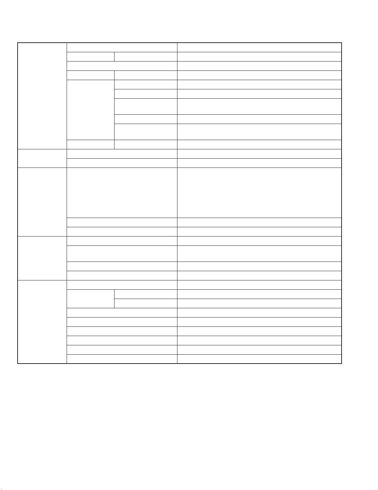
SPECIFICATION
Amplifier section Output power 140 W (70 W + 70 W) at 6Ω(10% THD)
Analog input AUX Sensitivity/Impedance (at 1 kHz): 400 mV/47 kΩ
USB input USB Ver.1.1
Digital output OPTICAL DIGITAL OUT -21 dBm to -15 dBm (660 nm ±30 nm)
VIDEO OUT Color system PAL
Video (composite) 1 V(p-p)/75Ω
S-video Y (luminance): 1 V(p-p)/75Ω
C (chrominance, burst): 0.3 V(p-p)/75Ω
RGB 0.7 V(p-p)/75Ω
COMPONENT (Y): 1 V(p-p)/75Ω
(PB/PR): 0.7 V(p-p)/75Ω
Speaker terminals Impedance 6Ω- 16Ω
Tuner section FM tuning range 87.50 MHz - 108.00 MHz
AM tuning range 522 kHz - 1 629 kHz
Disc player section Playable disc DVD Video/DVD Audio
CD/VCD/SVCD
CD-R/CD-RW (recorded in Audio CD/
Video CD/Super Video CD/MP3/JPEG/DivX format)
DVD-R (recorded in video/MP3/JPEG/DivX format)
DVD-RW/DVD-RAM (recorded in video/DVD-VR/MP3/JPEG/DivX
format)
Horizontal resolution 500 lines
Wow and flutter Immeasurable
General Power requirement AC 230 V , 50 Hz
Power consumption 150 W (at operation)
1.3 W (on standby)
Dimensions (approx.) 189 mm × 224 mm × 406 mm(W/H/D)
Mass (approx.) 6.5 kg
Speakers Type 2-way Bass-reflex type, Magnetically shielded
Speaker systems Woofer 12 cm cone × 1
Tweeter 4 cm cone × 1
Power handling capacity 70 W
Impedance 6Ω
Frequency range 45 Hz - 20 000 Hz
Sound pressure level 84 dB/W·m
Dimensions (approx.) 165 mm × 286 mm × 237 mm(W/H/D)
Mass (approx.) 2.8 kg each
Design and specifications are subject to change without notice.
1-2 (No.MB422)
Page 4

SECTION 1
PRECAUTIONS
1.1 Safety Precautions
(1) This design of this product contains special hardware and
many circuits and components specially for safety purposes. For continued protection, no changes should be made
to the original design unless authorized in writing by the
manufacturer. Replacement parts must be identical to
those used in the original circuits. Services should be performed by qualified personnel only.
(2) Alterations of the design or circuitry of the product should
not be made. Any design alterations of the product should
not be made. Any design alterations or additions will void
the manufacturers warranty and will further relieve the
manufacture of responsibility for personal injury or property
damage resulting therefrom.
(3) Many electrical and mechanical parts in the products have
special safety-related characteristics. These characteristics are often not evident from visual inspection nor can the
protection afforded by them necessarily be obtained by using replacement components rated for higher voltage, wattage, etc. Replacement parts which have these special
safety characteristics are identified in the Parts List of Service Manual. Electrical components having such features
are identified by shading on the schematics and by ( ) on
the Parts List in the Service Manual. The use of a substitute
replacement which does not have the same safety characteristics as the recommended replacement parts shown in
the Parts List of Service Manual may create shock, fire, or
other hazards.
(4) The leads in the products are routed and dressed with ties,
clamps, tubings, barriers and the like to be separated from
live parts, high temperature parts, moving parts and/or
sharp edges for the prevention of electric shock and fire
hazard. When service is required, the original lead routing
and dress should be observed, and it should be confirmed
that they have been returned to normal, after reassembling.
(5) Leakage shock hazard testing
After reassembling the product, always perform an isolation check on the exposed metal parts of the product (antenna terminals, knobs, metal cabinet, screw heads,
headphone jack, control shafts, etc.) to be sure the product
is safe to operate without danger of electrical shock.Do not
use a line isolation transformer during this check.
• Plug the AC line cord directly into the AC outlet. Using a
"Leakage Current Tester", measure the leakage current
from each exposed metal parts of the cabinet, particularly any exposed metal part having a return path to the
chassis, to a known good earth ground. Any leakage current must not exceed 0.5mA AC (r.m.s.).
• Alternate check method
Plug the AC line cord directly into the AC outlet. Use an
AC voltmeter having, 1,000
in the following manner. Connect a 1,500
paralleled by a 0.15
exposed metal part and a known good earth ground.
Measure the AC voltage across the resistor with the AC
Ω per volt or more sensitivity
Ω 10W resistor
µF AC-type capacitor between an
voltmeter.
Move the resistor connection to each exposed metal
part, particularly any exposed metal part having a return
path to the chassis, and measure the AC voltage across
the resistor. Now, reverse the plug in the AC outlet and
repeat each measurement. Voltage measured any must
not exceed 0.75 V AC (r.m.s.). This corresponds to 0.5
mA AC (r.m.s.).
AC VOLTMETER
(Having 1000
ohms/volts,
or more sensitivity)
0.15 F AC TYPE
Place this
probe on
1500 10W
Good earth ground
1.2 Warning
(1) This equipment has been designed and manufactured to
meet international safety standards.
(2) It is the legal responsibility of the repairer to ensure that
these safety standards are maintained.
(3) Repairs must be made in accordance with the relevant
safety standards.
(4) It is essential that safety critical components are replaced
by approved parts.
(5) If mains voltage selector is provided, check setting for local
voltage.
1.3 Caution
Burrs formed during molding may be left over on some parts
of the chassis.
Therefore, pay attention to such burrs in the case of preforming repair of this system.
1.4 Critical parts for safety
In regard with component parts appearing on the silk-screen
printed side (parts side) of the PWB diagrams, the parts that are
printed over with black such as the resistor ( ), diode ( )
and ICP ( ) or identified by the " " mark nearby are critical
for safety. When replacing them, be sure to use the parts of the
same type and rating as specified by the manufacturer.
(This regulation dose not Except the J and C version)
each exposed
metal part.
(No.MB422)1-3
Page 5
1.5 Safety Precautions (U.K only)
(1) This design of this product contains special hardware and many circuits and components specially for safety purposes. For con-
tinued protection, no changes should be made to the original design unless authorized in writing by the manufacturer. Replacement parts must be identical to those used in the original circuits.
(2) Any unauthorised design alterations or additions will void the manufacturer's guarantee; furthermore the manufacturer cannot
accept responsibility for personal injury or property damage resulting therefrom.
(3) Essential safety critical components are identified by ( ) on the Parts List and by shading on the schematics, and must never
be replaced by parts other than those listed in the manual. Please note however that many electrical and mechanical parts in
the product have special safety related characteristics. These characteristics are often not evident from visual inspection. Parts
other than specified by the manufacturer may not have the same safety characteristics as the recommended replacement parts
shown in the Parts List of the Service Manual and may create shock, fire, or other hazards.
(4) The leads in the products are routed and dressed with ties, clamps, tubings, barriers and the like to be separated from live parts,
high temperature parts, moving parts and/or sharp edges for the prevention of electric shock and fire hazard. When service is
required, the original lead routing and dress should be observed, and it should be confirmed that they have been returned to
normal, after re-assembling.
1.5.1 Warning
(1) Service should be performed by qualified personnel only.
(2) This equipment has been designed and manufactured to meet international safety standards.
(3) It is the legal responsibility of the repairer to ensure that these safety standards are maintained.
(4) Repairs must be made in accordance with the relevant safety standards.
(5) It is essential that safety critical components are replaced by approved parts.
(6) If mains voltage selector is provided, check setting for local voltage.
Burrs formed during molding may be left over on some parts of the chassis. Therefore,
pay attention to such burrs in the case of preforming repair of this system.
1-4 (No.MB422)
Page 6

SECTION 2
SPECIFIC SERVICE INSTRUCTIONS
This service manual does not describe SPECIFIC SERVICE INSTRUCTIONS.
(No.MB422)1-5
Page 7
SECTION 3
DISASSEMBLY
3.1 Disassembly of the main blocks of the set
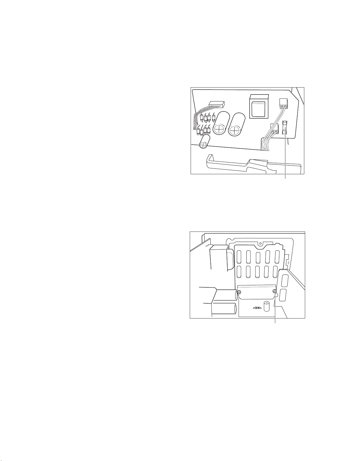
Replacement of the fuses and the power IC.
3.1.1 Replacing the fuses
(See Fig. C)
• Prior to performing the following procedure, remove the rear
cover.
(1) Replace the fuses inside.
Caution:
Be sure to use fuses with the specified ratings.
FUSE
(Location:F901)
Value: T1.25AL 250V
3.1.2 Replacing the power IC
(See Fig. D)
• Prior to performing the following procedure, remove the rear
cover.
(1) Remove the two screws H from the heat sink between the
power IC.
(2) Remove the solder fixing the power IC.
Fig.C
H
Fig.D
1-6 (No.MB422)
Page 8
3.2 MAIN BODY
A
A
A
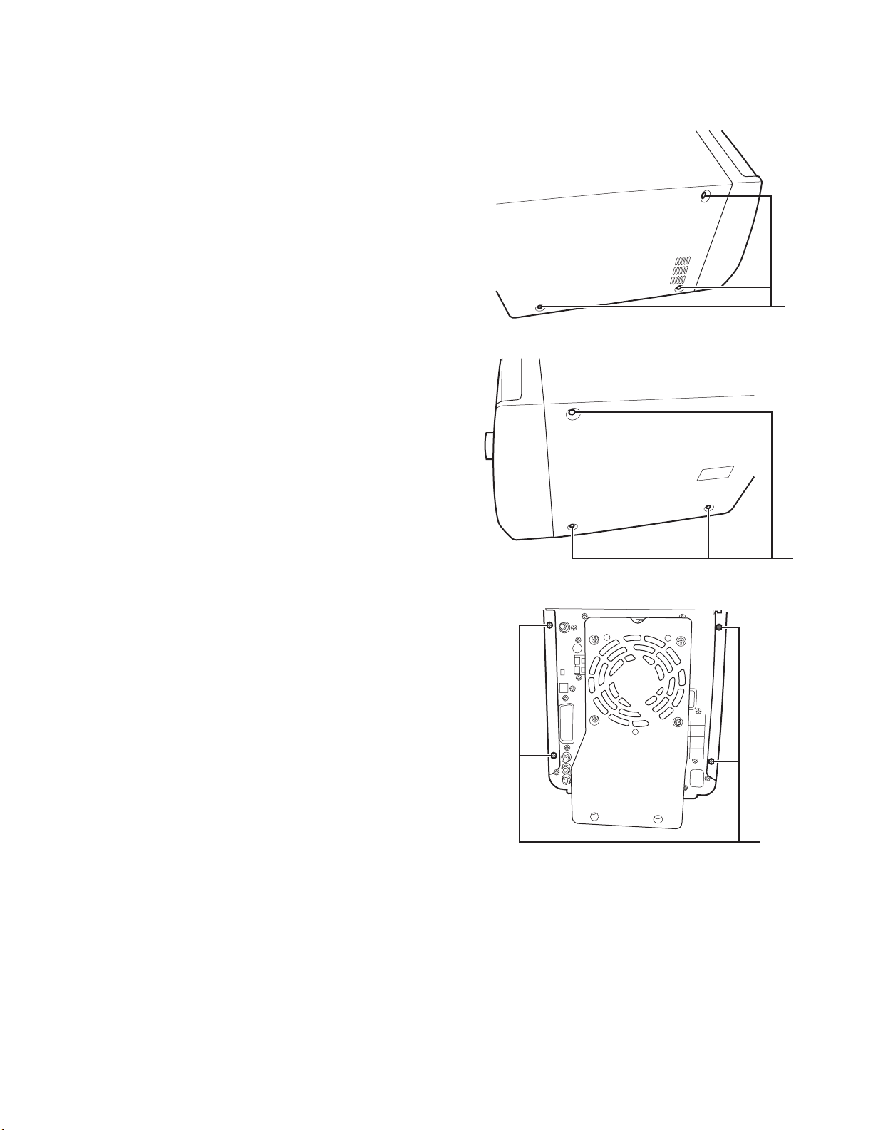
3.2.1 Removing the Metal Side Left and the Metal Side Right
(See Fig. 1-1, Fig. 1-2 and Fig. 1-3)
(1) Unscrew the 10 screws A from the Rear Panel, the Top
Cover and the Chassis Main.
(2) Remove the Metal Side Left and the Metal Side Right.
Fig.1-1
Fig.1-2
Fig.1-3
(No.MB422)1-7
Page 9
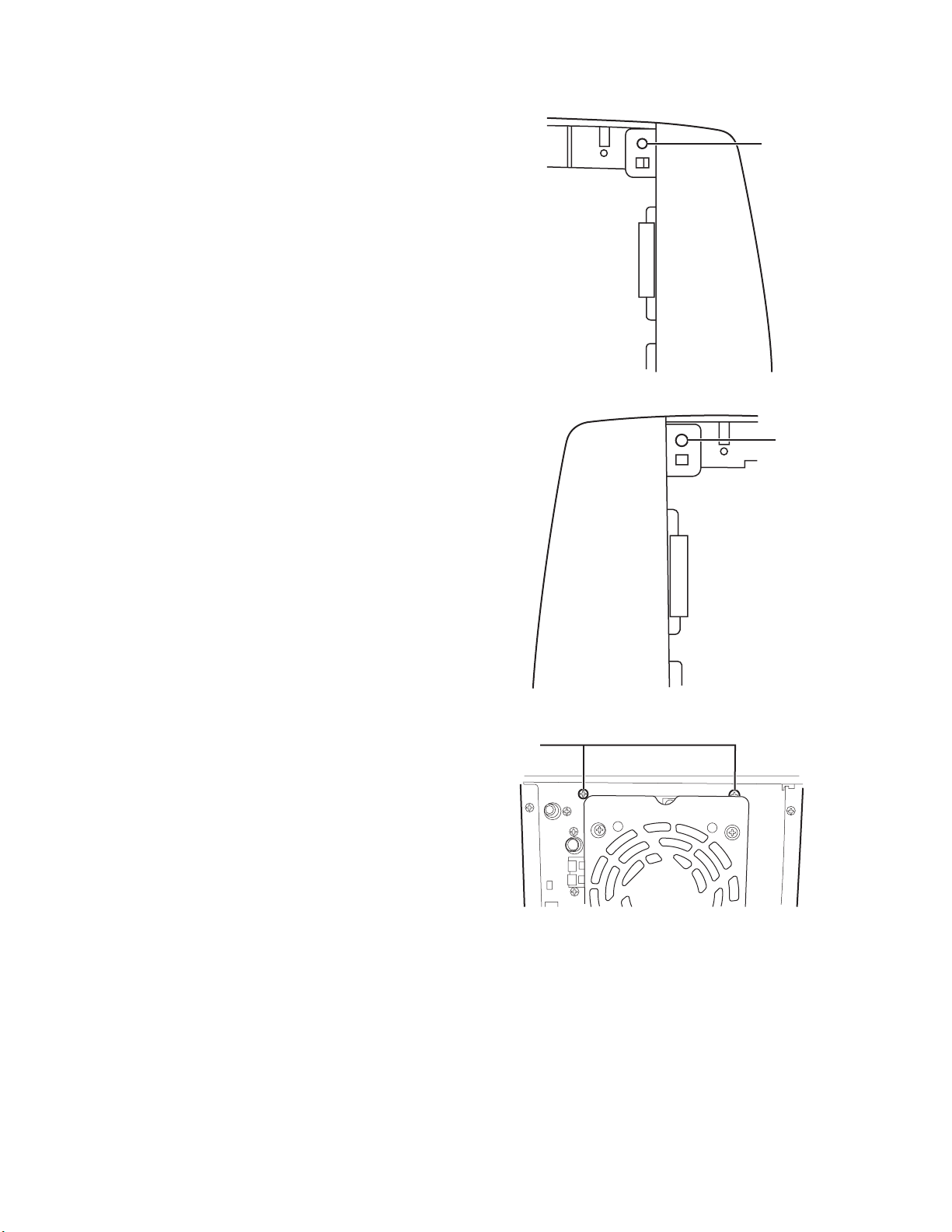
3.2.2 Removing the Top Cover
(See Fig. 2-1, Fig. 2-2 and Fig. 2-3)
(1) Unscrew the 2 Screws B and 2 Screws C.
(2) Removing the Top Cover.
B
Fig.2-1
B
C
Fig.2-2
Fig.2-3
1-8 (No.MB422)
Page 10

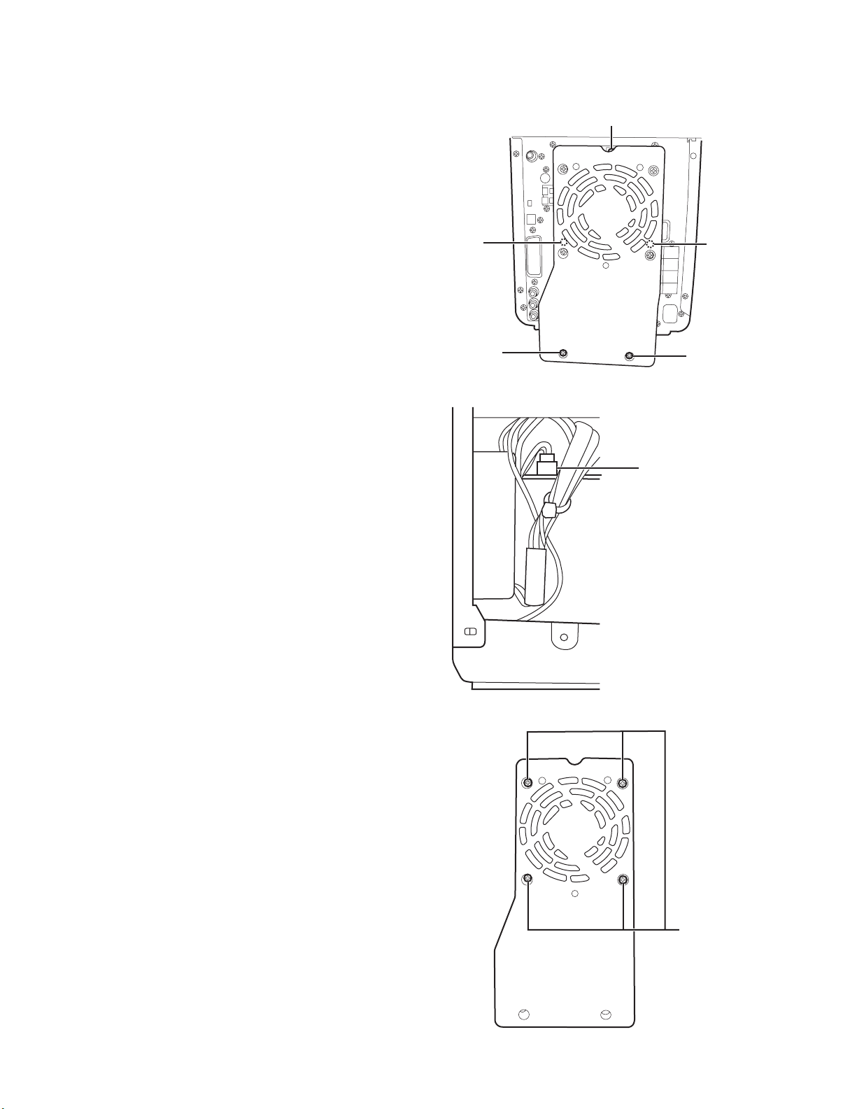
3.2.3 Removing the Cabinet Front
r
(See Fig. 3-1, Fig. 3-2, Fig. 3-3 and Fig. 3-4)
(1) Unscrew the 3 Screws D from the Chassis Main.
(2) Pulling out the 3 cable connectors from the Main Board unit
and the AMP Board unit then removing the Cabinet Front.
D
Fig.3-1
D
Fig.3-3
Connector
Fig.3-2
Connector
Connecto
Fig.3-4
D
(No.MB422)1-9
Page 11
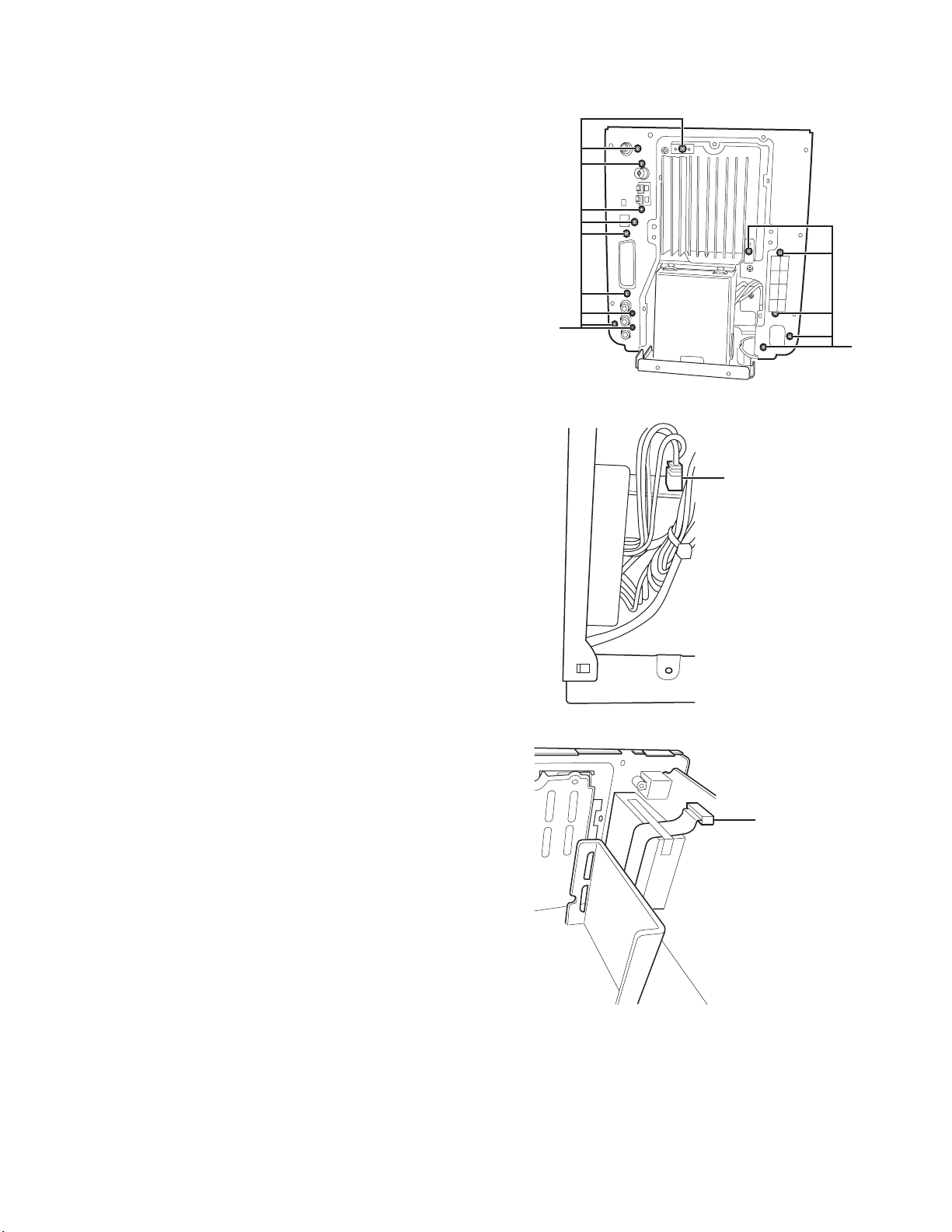
3.2.4 Removing the Cover Heat Sink and the Fan
(See Fig.4-1, Fig.4-2 and Fig.4-3)
(1) Unscrew the 5 Screws E from the Chassis Main and the
Rear Panel.
(2) Pulling out the cable connector from the AMP Board then
removing the Cover Heat Sink and the Fan.
(3) Unscrew the 4 Screws M from the Fan.
(4) Removing the Fan.
E
E
E
E
E
Fig.4-1
CONNECTOR
1-10 (No.MB422)
Fig.4-2
M
Fig.4-3
Page 12
3.2.5 Removing the Rear Panel the Tuner and the Speaker Board
(See Fig.5-1, Fig.5-2 and Fig.5-3)
(1) Unscrew the 15 screws C from the Main Board unit, the
Tuner, the Heat Sink, the Chassis Main and the scart
Board unit.
(2) Pulling out the 2 cable connectors from the AMP Board unit
and the Power Board unit then removing the Panel Rear,
the Tuner and the Speaker Board.
C
C
Fig.5-1
CONNECTOR
Fig.5-2
Fig.5-3
CONNECTOR
(No.MB422)1-11
Page 13
3.3 CABINET FRONTCHASSIS MAIN ASSEMBLY
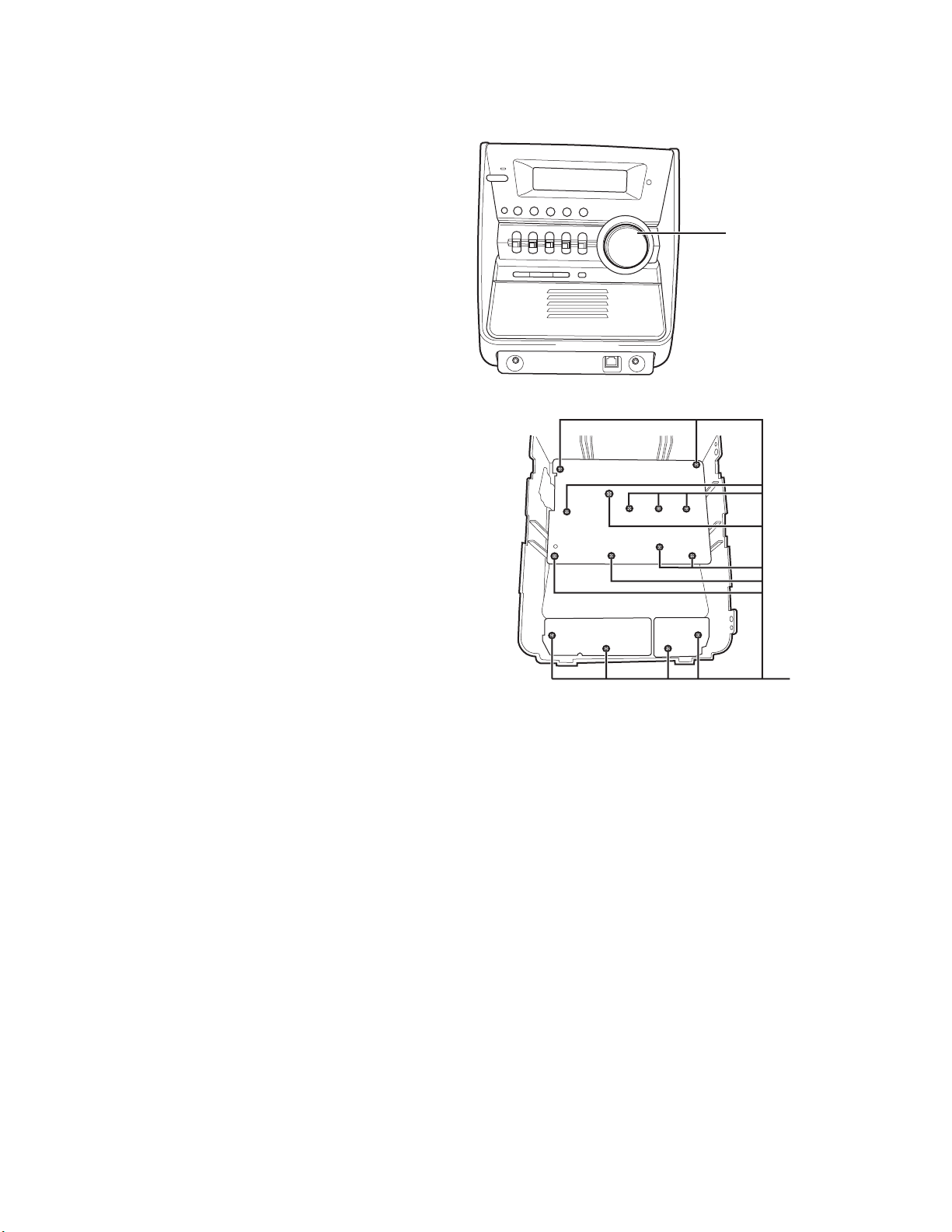
3.3.1 Removing the Knob Volume, the Display Board and the USB Board
(See Fig.6-1 and Fig.6-2)
• Prior to performing the following procedure before removing
the Display Board.
(1) Pulling out the Knob Volume from the Display Board.
(2) Unscrew the 15 screws F from the Cabinet Front, then tak-
ing out the Display Board and the USB Board.
KNOB VOLUME
Fig.6-1
Fig.6-2
F
1-12 (No.MB422)
Page 14
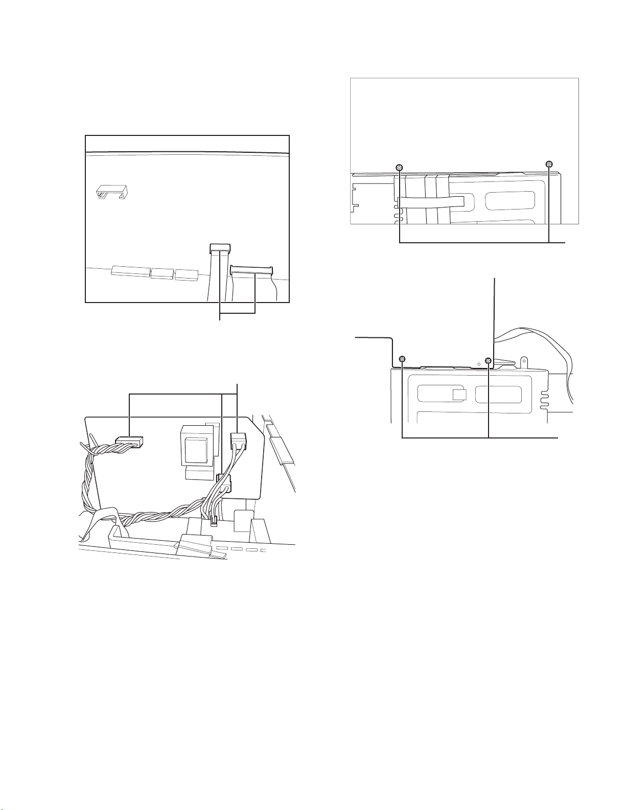
3.3.2 Removing the Main Board and the Power Board
(See Fig.7-1, Fig.7-2, Fig.7-3 and Fig.7-4)
(1) Pulling out the 5 cable connectors from Main Board unit
and the Power Board unit.
(2) Unscrew the 4 screws G from the Mechanism Holder.
(3) Separating the Main Board and the Power Board from the
AMP Board vertically.
CONNECTOR
G
Fig.7-3
Fig.7-1
CONNECTOR
Fig.7-2
G
Fig.7-4
(No.MB422)1-13
Page 15

3.3.3 Removing the AMP Board and the Main Heat Sink
(See Fig.8-1 and Fig.8-2)
(1) Unscrew the 3 screws G and 1 screw C from the Mecha-
nism Holder, then removing the AMP Board.
(2) Unscrew the 2 screws H then removing the Main Heat Sink.
G
C
Fig.8-1
1-14 (No.MB422)
HH
Fig.8-2
Page 16

3.3.4 Removing the Mechanism Holder
(See Fig.9-1 and Fig.9-2)
(1) Unscrew the 4 screws I from the Mechanism Holder.
(2) Removing the Mechanism Holder.
II
Fig.9-1
II
Fig.9-2
(No.MB422)1-15
Page 17

3.3.5 Removing the DVD Mechanism
(See Fig.10-1, Fig.10-2 and Fig.10-3)
Caution:
The DVD Mechanism may be taken out only when the Rear
Panel, the Tuner, the Speaker
Board, the Main Board, the Power Board, the AMP Board, the
Mechanism Front Holder and the Mechanism Back Holder
have been taken away.
(1) Unscrew the 4 screws J from the Chassis Main.
(2) Separating the DVD Mechanism, the Mechanism Front
Holder and the Mechanism Back Holder from the Chassis
Main vertically.
(3) Unscrew the 4 screws K from the Mechanism, then remov-
ing the Mechanism Front Holder and the Mechanism Back
Holder.
JJ
Fig.10-1
K
K
JJ
3.3.6 Removing the Transformer
(See Fig.11)
(1) Unscrew the 4 screws L from the Chassis Main.
(2) Taking out the Bushing then removing the Silicon Steel
Sheet and the Transformer.
Fig.10-2
CD MECH Assembly
KK
Fig.10-3
1-16 (No.MB422)
L
LL
Fig.11
L
Page 18

SECTION 4
ADJUSTMENT
4.1 Measurement instruments required for adjustment
(1) Low frequency oscillator.
This oscillator should have a capacity to output 0dB to
600Ω at an oscillation frequency of 50Hz-20kHz.
(2) Attenuator impedance : 600Ω
(3) Electronic voltmeter
(4) Frequency counter
(5) Wow flutter meter
(6) Test tape
VT712 : For Tape speed and wow flutter (3kHz)
VT703 : For Head angle (10kHz)
(7) Blank tape
TAPE l : AC-225 TAPE II : AC-514
(8) Torque gauge : For play and back tension forward:
TW2111A, Reverse: TW2121A Fast Forward and Rewind:
TW2231A
(9) Test disc: CTS-1000(12cm),GRG-1211(8cm)
(10) Jitter meter
4.2 Measurement conditions
Power supply voltage :AC 230V (50Hz)
Measurement output
terminal
4.3 Radio input signal
AM modulation frequency :400Hz
Modulation factor :30%
FM modulation frequency :1kHz
Frequency displacement :22.5kHz
:Speaker out
:TP101(Measuring for TUNER/DECK/CD)
:Dummy load 6Ω
4.4 Frequency Range
AM 522kHz to 1629kHz
FM 87.5MHz to 108MHz
4.5 Standard measurement positions of volume and switch
Power :Standby (Light STANDBY Indicator)
Sound Turbo ll / BASS/ TREBLE OFF
AHB PRO :OFF
Main VOL. :0 Minimum
Travers mecha set position :Disc 1
4.6 Precautions for measurement
(1) Apply 30pF and 33kΩ to the IF sweeper output side and
0.082 F and 100kΩ in series to the sweeper input side.
(2) The IF sweeper output level should be made as low as pos-
sible within the adjustable range.
(3) Since the IF sweeper is a fixed device, there is no need to
adjust this sweeper.
(4) Since a ceramic oscillator is used, there is no need to per-
form any MPX adjustment.
(5) Since a fixed coil is used, there is no need to adjust the FM
tracking.
(6) The input and output earth systems are separated.
In case of simultaneously measuring the voltage in both of
the input and output systems with an electronic voltmeter
for two channels, therefore, the earth should be connected
particularly.
(7) In the case of BTL connection amplifier, the minus terminal
of speaker is not for earthing. Therefore, be sure not to connect any other earth terminal to this terminal. This system
is of an OTL system.
SECTION 5
TROUBLESHOOTING
This service manual does not describe TROUBLESHOOTING.
(No.MB422)1-17
Page 19

Victor Company of Japan, Limited
AV & MULTIMEDIA COMPANY AUDIO/VIDEO SYSTEMS CATEGORY 10-1,1chome,Ohwatari-machi,Maebashi-city,371-8543,Japan
(No.MB422)
Printed in Japan
VPT
Page 20

PARTS LIST
[ UX-GD7 ]
* All printed circuit boards and its assemblies are not available as service parts.
Area suffix
B ------------------------------- U.K.
E ----------- Continental Europe
EN ------------ Northern Europe
EV -------------- Eastern Europe
EE --------- Russian Federation
MB422
- Contents -
Exploded view of general assembly and parts list (Block No.M1)
Electrical parts list (Block No.01~05)
Packing materials and accessories parts list (Block No.M3)
3- 2
3- 5
3-12
3-1
Page 21

Exploded view of general assembly and parts list
a
Block No.
27
M
M
1
M
45
44
19
54
46
21
18
20
16
46
21
46
F901
53
22
40
47
23
25
15
24
17
26
48
46
28
46
43
46
46
Amp bo
14
3-2
44
43
Power trans
board
40
12
41
13
42
11
42
9
41
Page 22

46
43
46
46
44
29
28
42
Amp board
14
11
Front board
40
42
39
39
Main board
31
10
34
32
30
33
36
43
37
35
8
43
44
37
1
8
38
2
6
3
41
38
38
9
The parts without symbol number are not service.
7
4
5
3-3
Page 23

General Assembly
Symbol No. Part No. Part Name Description Local
1 BI1080999101V1 FRONT CABINET HIPS-8002 94V2
2 BI1081000101V1 WINDOW LENS SAN-C-2495 94HB
3 BI1080800101V1 VOLUME KNOB ABS-T700 94HB
4 BI1080920101V1 USB PANEL HIPS-470 94HB
5 BI1080930101V1 DVD DOOR HIPS-470 94HB
6 BI1080980101V1 DISC PANEL ABS-T700 94HB
7 BI202917010101 DVD DOOR SPRING SUS304
8 BI3021910101V1 RUBBER MAT SILICON RUBBER(x2)
9 BI3021040101V1 RUBBER FOOT EVA(x4)
10 BI1080960101V1 LED LENS L PMMA-CP-51
11 BI2029130101W1 MECH FRONT HLDR SECC T=1.0mm
12 BI2029100101W1 MAIN CHASSIS SECC T=1.0mm
13 BI2029140101W1 MECH BACK HLDR SECC T=1.0mm
14 BI253050001300V 5DVD LOADER
15 BI211011134001 POWER TRANS AC 230 TYPE
16 BI2029080101W1 SIDE PANEL L SECC T=0.6mm
17 BI3021770101V1 CUSHION NR
18 BI301789010101 BUSHING
19 BI1081649101X1 HEAT SINK COVER PA-765A(+) 94V0
20 BI2400251V FAN DC 12V
21 BI2029600101W1 HEAT SINK HLDR SECC T=1.0mm(x2)
22 BI2029110101W1 REAR PANEL SECC T=0.8mm
23 BIZ25095401VV TUNER PACK
24 BI202966010101 SHEET SILICON STEEL T=0.5mm
25 BI202959010101 HEAT SINK AL
26 BI202958010101 HEAT SINK SMALL AL
27 BI1080899101V1 TOP COVER HIPS-8002 94V2
28 BI2029120101W1 MECH HOLDER SECC T=0.8mm
29 BI2029090101W1 SIDE PANEL R SECC T=0.6mm
30 BI1080870101V1 LCD HOLDER ABS-T700 94HB
31 BI167020001001V LCD LD802 BLUE
32 BI202814010101 HOLDER SENSOR
33 BI1080970101V1 POWER BUTTON ABS-T700 94HB
34 BI1081010101V1 FUNCTION BUTTON ABS-T700 94HB
35 BI1080950101V1 LED LENS R PMMA-CP-51
36 BI1080940101V1 LENS PMMA-CP-51
37 BIKT000625P11 SCREW 3xL10(x2)
38 BIKT000606B3 SCREW 3xL6(x3)
39 BIBT000418 SCREW 2.6 XL8(x15)
40 BIBT000603P3 SCREW 3xL4(x6)
41 BIRT000605S3 SCREW 3xL5(x4)
42 BIBT000606B3W SCREW 3xL6(x4)
43 BIRT000606B3W SCREW 3xL6(x7)
44 BIRT000608B1W SCREW 3xL8(x10)
45 BIRT000608B2W SCREW 3xL8(x9)
46 BIRT000608B3W2 SCREW 3xL8(x23)
47 BIPMW001101S3 SCREW 4.0XL6 METAL(x4)
48 BIBT000654 SCREW BT 3X16(x2)
53 BI403081 FUSE F901 1.25A 250V
54 BI1401441V POWER CORD B
54 BI1401741X POWER CORD E,EE,EN,EV
Block No. [M][1][M][M]
3-4
Page 24

Electrical parts list
Main board
Block No. [0][1]
Symbol No.
IC401 BD3881FV IC BI112721V
IC402 NJM4558MD IC BI103311V
IC403 NJM4558MD IC BI103311V
IC404 NJM4558MD IC BI103311V
IC501 MM1623XFBE IC BI117991V
IC550 NJM2233M IC BI117371X
IC601 MN101C49GBB IC BI119241V
IC602 M24C02 IC BI111731V
IC701 BU1924F IC BI113131
Q401 KTC3875 TRANSISTOR BI2KTC3875YA014
Q402 KTC3875 TRANSISTOR BI2KTC3875YA014
Q403 DTC323TK DIGI TRANSISTOR BI2DTC323TKA011
Q404 DTC323TK DIGI TRANSISTOR BI2DTC323TKA011
Q406 KTA1267GR TRANSISTOR BI2KTA1267GP000
Q407 KTC3875 TRANSISTOR BI2KTC3875YA014
Q408 DTC323TK DIGI TRANSISTOR BI2DTC323TKA011
Q409 KTC3198GR TRANSISTOR BI2KTC3198GP00
Q411 KTC3875 TRANSISTOR BI2KTC3875YA014
Q412 KTC3875 TRANSISTOR BI2KTC3875YA014
Q420 DTA124EK DIGI TRANSISTOR BI2DTA124EKA008
Q551 DTC124EKA DIGI TRANSISTOR BI2DTC124EKA018
Q552 DTC124EKA DIGI TRANSISTOR BI2DTC124EKA018
Q553 KRA107S TRANSISTOR BI2KRA107SA0000
Q554 DTC124EKA DIGI TRANSISTOR BI2DTC124EKA018
Q555 KTC3875 TRANSISTOR BI2KTC3875YA014
Q601 KTC3875 TRANSISTOR BI2KTC3875YA014
Q602 DTC114TK DIGI TRANSISTOR BI2DTC114TKA011
Q604 DTC114EK DIGI TRANSISTOR BI2DTC114EKA018
Q611 DTC114EK DIGI TRANSISTOR BI2DTC114EKA018
Q612 DTC114EK DIGI TRANSISTOR BI2DTC114EKA018
Q613 DTC114EK DIGI TRANSISTOR BI2DTC114EKA018
Q614 DTC114EK DIGI TRANSISTOR BI2DTC114EKA018
D401 UZ4.7BSA Z DIODE BI3UZ4.7BSAM000
D402 UZ4.7BSA Z DIODE BI3UZ4.7BSAM000
D403 UZ9.1BSC Z DIODE BI3UZ91BSCM000V
D404 UZ9.1BSC Z DIODE BI3UZ91BSCM000V
D405 1SS133 FR DIODE BI31SS133M000V7
D406 1SS133 FR DIODE BI31SS133M000V7
D407 1SS133 FR DIODE BI31SS133M000V7
D408 UZ8.2BSB Z DIODE BI3UZ82BSBM000V
D415 UZ6.8BSB Z DIODE BI3UZ6.8BSBM000
D580 1SS133 FR DIODE BI31SS133M000V7
D581 1SS133 FR DIODE BI31SS133M000V7
D601 1N4002 DIODE BI31N4002M000V3
D602 1SS133 FR DIODE BI31SS133M000V7
D603 1SS133 FR DIODE BI31SS133M000V7
D604 1SS133 FR DIODE BI31SS133M000V7
D605 UZ6.2BSB Z DIODE BI3UZ6.2BSBM000
D615 UZ5.1BSB Z DIODE BI3UZ5.1BSBM000
D620 1N4002 DIODE BI31N4002M000V3
C225 BICC153500KA04 C CAPACITOR 0.015uF 50V
C226 BICC153500KA04 C CAPACITOR 0.015uF 50V
C262 BICE225500MP01 E CAPACITOR 2.2uF 50V
C263 BICE225500MP01 E CAPACITOR 2.2uF 50V
C307 BICE476250MP01 E CAPACITOR 47uF 25V
C308 BICE476250MP01 E CAPACITOR 47uF 25V
C401 BICC822500KA04 C CAPACITOR 8200pF 50V
C402 BICC822500KA04 C CAPACITOR 8200pF 50V
C403 BICE475500MP01 E CAPACITOR 4.7uF 50V
C404 BICE475500MP01 E CAPACITOR 4.7uF 50V
C405 BICE104500MP01 E CAPACITOR 0.1uF 50V
C406 BICE104500MP01 E CAPACITOR 0.1uF 50V
C407 BICC683160KA04 C CAPACITOR 0.068uF 16V
C408 BICC683160KA04 C CAPACITOR 0.068uF 16V
C409 BICE474500MP01 E CAPACITOR 0.47uF 50V
C410 BICE474500MP01 E CAPACITOR 0.47uF 50V
C411 BICC101500JA04 C CAPACITOR 100pF 50V
C412 BICC104500ZA04 C CAPACITOR 0.1uF 50V
C413 BICE227100MP01 E CAPACITOR 220uF 10V
Part No. Part Name Description Local
Symbol No.
C414 BICC104500ZA04 C CAPACITOR 0.1uF 50V
C415 BICE107100MP01 E CAPACITOR 100uF 10V
C416 BICE107160MP11 E CAPACITOR 100uF 16V
C417 BICE107160MP11 E CAPACITOR 100uF 16V
C418 BICC222500KA04 C CAPACITOR 2200pF 50V
C419 BICC222500KA04 C CAPACITOR 2200pF 50V
C420 BICE226250MP01 E CAPACITOR 22uF 25V
C421 BICE226250MP01 E CAPACITOR 22uF 25V
C422 BICM124101KP01 M CAPACITOR 0.12uF 100V
C423 BICM124101KP01 M CAPACITOR 0.12uF 100V
C424 BICE107160MP11 E CAPACITOR 100uF 16V
C425 BICE107160MP11 E CAPACITOR 100uF 16V
C426 BICM124101KP01 M CAPACITOR 0.12uF 100V
C427 BICM124101KP01 M CAPACITOR 0.12uF 100V
C428 BICE475500MP11 E CAPACITOR 4.7uF 50V
C429 BICE475500MP11 E CAPACITOR 4.7uF 50V
C430 BICC104500ZA04 C CAPACITOR 0.1uF 50V
C431 BICC104500ZA04 C CAPACITOR 0.1uF 50V
C432 BICC102500JA04 C CAPACITOR 1000pF 50V
C433 BICC102500JA04 C CAPACITOR 1000pF 50V
C434 BICE475500MP01 E CAPACITOR 4.7uF 50V
C435 BICC102500JA04 C CAPACITOR 1000pF 50V
C436 BICC102500JA04 C CAPACITOR 1000pF 50V
C437 BICE226500MP01 E CAPACITOR 22uF 50V
C438 BICE226500MP01 E CAPACITOR 22uF 50V
C439 BICC102500JA04 C CAPACITOR 1000pF 50V
C440 BICC102500JA04 C CAPACITOR 1000pF 50V
C441 BICC331500JA04 C CAPACITOR 330pF 50V
C442 BICC331500JA04 C CAPACITOR 330pF 50V
C443 BICC104500ZA04 C CAPACITOR 0.1uF 50V
C444 BICC104500ZA04 C CAPACITOR 0.1uF 50V
C445 BICC332500KA04 C CAPACITOR 3300pF 50V
C446 BICC332500KA04 C CAPACITOR 3300pF 50V
C447 BICE226500MP01 E CAPACITOR 22uF 50V
C448 BICE226500MP01 E CAPACITOR 22uF 50V
C449 BICE107100MP01 E CAPACITOR 100uF 10V
C450 BICC104500KA04 C CAPACITOR 0.1uF 50V
C451 BICC224250KA02 C CAPACITOR 0.22uF 25V
C452 BICC104500ZA04 C CAPACITOR 0.1uF 50V
C453 BICE105500MP01 E CAPACITOR 1uF 50V
C454 BICC104500KA04 C CAPACITOR 0.1uF 50V
C455 BICC103500KA04 C CAPACITOR 0.01uF 50V
C456 BICC104500ZA04 C CAPACITOR 0.1uF 50V
C457 BICE334500MP11 E CAPACITOR 0.33uF 50V
C459 BICC101500JA04 C CAPACITOR 100pF 50V
C460 BICC102500JA04 C CAPACITOR 1000pF 50V
C461 BICE476160MP01 E CAPACITOR 47uF 16V
C462 BICC223500KA04 C CAPACITOR 0.022uF 50V
C464 BICC101500JA04 C CAPACITOR 100pF 50V
C465 BICC101500JA04 C CAPACITOR 100pF 50V
C466 BICC101500JA04 C CAPACITOR 100pF 50V
C467 BICC101500JA04 C CAPACITOR 100pF 50V
C468 BICE107160MP01 E CAPACITOR 100uF 16V
C469 BICH103500KM01 C CAPACITOR 0.01uF 50V
C470 BICC101500JA04 C CAPACITOR 100pF 50V
C471 BICE107100MP01 E CAPACITOR 100uF 10V
C472 BICC103500KA04 C CAPACITOR 0.01uF 50V
C480 BICE475500MP11 E CAPACITOR 4.7uF 50V
C507 BICE477063MP01 E CAPACITOR 470uF 6.3V
C508 BICC181500JA04 C CAPACITOR 180pF 50V
C509 BICE477063MP01 E CAPACITOR 470uF 6.3V
C510 BICC181500JA04 C CAPACITOR 180pF 50V
C511 BICE477063MP01 E CAPACITOR 470uF 6.3V
C512 BICC181500JA04 C CAPACITOR 180pF 50V
C513 BICH103500KM01 C CAPACITOR 0.01uF 50V
C514 BICE476160MP01 E CAPACITOR 47uF 16V
C515 BICE105500MP01 E CAPACITOR 1uF 50V
C516 BICE105500MP01 E CAPACITOR 1uF 50V
C517 BICE105500MP01 E CAPACITOR 1uF 50V
C518 BICE107100MP01 E CAPACITOR 100uF 10V
C519 BICC104500ZA04 C CAPACITOR 0.1uF 50V
C520 BICC104500KA04 C CAPACITOR 0.1uF 50V
C550 BICE476160MP01 E CAPACITOR 47uF 16V
C551 BICC104500KA04 C CAPACITOR 0.1uF 50V
C552 BICE105500MP01 E CAPACITOR 1uF 50V
C553 BICC103500KA04 C CAPACITOR 0.01uF 50V
Part No. Part Name Description Local
3-5
Page 25

Symbol No.
Part No. Part Name Description Local
Symbol No.
Part No. Part Name Description Local
C554 BICE477063MP01 E CAPACITOR 470uF 6.3V
C555 BICC330500JA04 C CAPACITOR 33pF 50V
C556 BICE477063MP01 E CAPACITOR 470uF 6.3V
C557 BICC330500JA04 C CAPACITOR 33pF 50V
C558 BICE477063MP01 E CAPACITOR 470uF 6.3V
C559 BICC330500JA04 C CAPACITOR 33pF 50V
C560 BICE477063MP01 E CAPACITOR 470uF 6.3V
C561 BICC330500JA04 C CAPACITOR 33pF 50V
C562 BICE108063MP01 E CAPACITOR 1000uF 6.3V
C565 BICE108063MP01 E CAPACITOR 1000uF 6.3V
C601 BICE107100MP01 E CAPACITOR 100uF 10V
C602 BICE475500MP01 E CAPACITOR 4.7uF 50V
C603 BICE225500MP01 E CAPACITOR 2.2uF 50V
C604 BICE108100MP01 E CAPACITOR 1000uF 10V
C605 BICC104500ZA04 C CAPACITOR 0.1uF 50V
C606 BICC104500ZA04 C CAPACITOR 0.1uF 50V
C607 BICE107100MP01 E CAPACITOR 100uF 10V
C608 BICC103500KA04 C CAPACITOR 0.01uF 50V
C609 BICC200500JA04 C CAPACITOR 20pF 50V
C610 BICC270500JA04 C CAPACITOR 27pF 50V
C612 BICC101500JA04 C CAPACITOR 100pF 50V
C613 BICC101500JA04 C CAPACITOR 100pF 50V
C614 BICH104500KM01 C CAPACITOR 0.1uF 50V
C615 BICH104500KM01 C CAPACITOR 0.1uF 50V
C616 BICC331500JA04 C CAPACITOR 330pF 50V
C711 BICC101500JA04 C CAPACITOR 100pF 50V
C712 BICC102500JA04 C CAPACITOR 1000pF 50V
C720 BICC224250KA02 C CAPACITOR 0.22uF 25V
C750 BICE225500MP01 E CAPACITOR 2.2uF 50V
C751 BICC271500JA04 C CAPACITOR 270pF 50V
C752 BICE225500MP01 E CAPACITOR 2.2uF 50V
C753 BICC561500KA04 C CAPACITOR 560pF 50V
C754 BICE225500MP01 E CAPACITOR 2.2uF 50V
C755 BICC330500JA04 C CAPACITOR 33pF 50V
C756 BICC330500JA04 C CAPACITOR 33pF 50V
C757 BICC101500JA04 C CAPACITOR 100pF 50V
C758 BICC101500JA04 C CAPACITOR 100pF 50V
Ω
Ω
Ω
Ω
Ω
Ω
1/10W
Ω
1/10W
Ω
1/10W
Ω
1/10W
1/10W
1/10W
1/8W J
Ω
1/10W
Ω
1/10W
Ω
1/10W
Ω
1/10W
Ω
1/10W
Ω
1/10W
Ω
1/10W
Ω
1/10W
Ω
1/10W
Ω
1/10W
Ω
1/10W
Ω
1/10W
Ω
1/10W
Ω
1/10W
Ω
1/10W
Ω
1/4W
Ω
1/4W
1/4W
1/4W
Ω
1/10W
Ω
1/10W
Ω
1/10W
Ω
1/10W
Ω
1/10W
Ω
1/10W
Ω
1/8W
Ω
1/8W
Ω
1/8W
Ω
1/8W
Ω
1/10W
Ω
1/10W
Ω
1/10W
Ω
1/10W
R301 BIRC1830105A00 C RESISTOR 18K
R302 BIRC1830105A00 C RESISTOR 18K
R303 BIRC3320105A00 C RESISTOR 3.3K
R304 BIRC3320105A00 C RESISTOR 3.3K
R309 BIRC0000105A00 C RESISTOR 0
R371 BIRC1020105A00 C RESISTOR 1K
R372 BIRC1020085M00 C RESISTOR 1K
R400 BIRC5620105A00 C RESISTOR 5.6K
R401 BIRC5630105A00 C RESISTOR 56K
R402 BIRC5630105A00 C RESISTOR 56K
R403 BIRC1040105A00 C RESISTOR 100K
R404 BIRC1040105A00 C RESISTOR 100K
R405 BIRC6830105A00 C RESISTOR 68K
R406 BIRC6830105A00 C RESISTOR 68K
R407 BIRC2220105A00 C RESISTOR 2.2K
R408 BIRC2220105A00 C RESISTOR 2.2K
R409 BIRC1030105A00 C RESISTOR 10K
R410 BIRC4720105A00 C RESISTOR 4.7K
R411 BIRC4720105A00 C RESISTOR 4.7K
R412 BIRC2240105A00 C RESISTOR 220K
R413 BIRC1040105A00 C RESISTOR 100K
R414 BIRC2220105A00 C RESISTOR 2.2K
R415 BIRC4710045N00 C RESISTOR 470
R416 BIRC4710045N00 C RESISTOR 470
R417 BIRC8200045M00 C RESISTOR 82
R418 BIRC8200045M00 C RESISTOR 82
R419 BIRC1530105A00 C RESISTOR 15K
R420 BIRC1530105A00 C RESISTOR 15K
R421 BIRC8210105A00 C RESISTOR 820
R422 BIRC8210105A00 C RESISTOR 820
R425 BIRC3320105A00 C RESISTOR 3.3K
R426 BIRC3320105A00 C RESISTOR 3.3K
R427 BIRC1220085M00 C RESISTOR 1.2K
R428 BIRC1220085M00 C RESISTOR 1.2K
R429 BIRC4720085N00 C RESISTOR 4.7K
R430 BIRC4720085N00 C RESISTOR 4.7K
R431 BIRC2220105A00 C RESISTOR 2.2K
R432 BIRC2220105A00 C RESISTOR 2.2K
R433 BIRC2220105A00 C RESISTOR 2.2K
R434 BIRC2220105A00 C RESISTOR 2.2K
R435 BIRC1220105A00 C RESISTOR 1.2KΩ 1/10W
R436 BIRC1220105A00 C RESISTOR 1.2K
R437 BIRC0000105A00 C RESISTOR 0
R438 BIRC0000105A00 C RESISTOR 0
R439 BIRC2220105A00 C RESISTOR 2.2K
R440 BIRC2220105A00 C RESISTOR 2.2K
R441 BIRC1040105A00 C RESISTOR 100K
R442 BIRC1040105A00 C RESISTOR 100K
R443 BIRC2220105A00 C RESISTOR 2.2K
R445 BIRC1230105A00 C RESISTOR 12K
R446 BIRC1230105A00 C RESISTOR 12K
R447 BIRC2220105A00 C RESISTOR 2.2K
R448 BIRC2220105A00 C RESISTOR 2.2K
R449 BIRC1520105A00 C RESISTOR 1.5K
R450 BIRC1520105A00 C RESISTOR 1.5K
R451 BIRC8220105A00 C RESISTOR 8.2K
R452 BIRC8220105A00 C RESISTOR 8.2K
R453 BIRC8210105A00 C RESISTOR 820
R454 BIRC8210105A00 C RESISTOR 820
R455 BIRC3920105A00 C RESISTOR 3.9K
R456 BIRC3920105A00 C RESISTOR 3.9K
R457 BIRC4720105A00 C RESISTOR 4.7K
R458 BIRC4720105A00 C RESISTOR 4.7K
R459 BIRC1010085M00 C RESISTOR 100
R460 BIRC1010085M00 C RESISTOR 100
R461 BIRC3310105A00 C RESISTOR 330
R462 BIRC1010085M00 C RESISTOR 100
R463 BIRC1010085M00 C RESISTOR 100
R465 BIRC2220105A00 C RESISTOR 2.2K
R466 BIRC3320105A00 C RESISTOR 3.3K
R467 BIRC1020085M00 C RESISTOR 1K
R468 BIRC1040105A00 C RESISTOR 100K
R469 BIRC1040105A00 C RESISTOR 100K
R470 BIRC1020105A00 C RESISTOR 1K
R471 BIRC1820105A00 C RESISTOR 1.8K
R472 BIRC3320105A00 C RESISTOR 3.3K
R473 BIRC1040105A00 C RESISTOR 100K
R474 BIRC5610105A00 C RESISTOR 560
R475 BIRC2220085M00 C RESISTOR 2.2K
R476 BIRC4730105A00 C RESISTOR 47K
R478 BIRC1010085M00 C RESISTOR 100
R479 BIRC1010085M00 C RESISTOR 100
R481 BIRC3300045M00 C RESISTOR 33
R482 BIRC1010105A00 C RESISTOR 100
R483 BIRC1000105A00 C RESISTOR 10
R484 BIRC1040105A00 C RESISTOR 100K
R485 BIRC1020105A00 C RESISTOR 1K
R486 BIRC4720105A00 C RESISTOR 4.7K
R487 BIRC4720105A00 C RESISTOR 4.7K
R488 BIRC5620105A00 C RESISTOR 5.6K
R489 BIRC4710105A00 C RESISTOR 470
R490 BIRC4710105A00 C RESISTOR 470
R491 BIRC1040105A00 C RESISTOR 100K
R492 BIRC1040105A00 C RESISTOR 100K
R493 BIRC2240105A00 C RESISTOR 220K
R494 BIRC2240105A00 C RESISTOR 220K
R495 BIRC3330085M00 C RESISTOR 33K
R496 BIRC2730085N00 C RESISTOR 27K
R497 BIRC2730085N00 C RESISTOR 27K
R498 BIRC1030105A00 C RESISTOR 10K
R499 BIRC1030105A00 C RESISTOR 10K
R507 BIRC7500105A00 C RESISTOR 75
R508 BIRC1030105A00 C RESISTOR 10K
R509 BIRC7500105A00 C RESISTOR 75
R510 BIRC1030105A00 C RESISTOR 10K
R511 BIRC7500105A00 C RESISTOR 75
R512 BIRC1030105A00 C RESISTOR 10K
R513 BIRC2210105A00 C RESISTOR 220
R514 BIRC3020105A00 C RESISTOR 3K
R515 BIRC3020105A00 C RESISTOR 3K
R516 BIRC2210105A00 C RESISTOR 220
R517 BIRC3020105A00 C RESISTOR 3K
R518 BIRC2210105A00 C RESISTOR 220
R519 BIRC1210105A00 C RESISTOR 120
R520 BIRC6810105A00 C RESISTOR 680
R521 BIRC6810105A00 C RESISTOR 680
R522 BIRC1210105A00 C RESISTOR 120
R541 BIRC1020085M00 C RESISTOR 1K
Ω
1/10W
Ω
1/10W
Ω
Ω
Ω
Ω
Ω
Ω
Ω
Ω
Ω
Ω
Ω
Ω
Ω
Ω
Ω
Ω
Ω
Ω
Ω
Ω
Ω
Ω
Ω
Ω
Ω
Ω
Ω
Ω
Ω
Ω
Ω
Ω
Ω
1/10W
Ω
1/10W
Ω
1/10W
Ω
1/10W
Ω
1/10W
Ω
1/10W
Ω
1/10W
Ω
1/10W
Ω
1/10W
Ω
1/10W
Ω
1/10W
Ω
1/10W
Ω
1/10W
Ω
1/10W
1/10W
1/10W
Ω
1/10W
Ω
1/10W
Ω
1/10W
Ω
1/10W
1/8W J
1/8W J
1/10W
1/8W J
1/8W J
Ω
1/10W
Ω
1/10W
1/8W J
Ω
1/10W
Ω
1/10W
1/10W
Ω
1/10W
Ω
1/10W
Ω
1/10W
1/10W
Ω
1/8W
Ω
1/10W
1/8W J
1/8W J
1/4W
1/10W
1/10W
Ω
1/10W
1/10W
Ω
1/10W
Ω
1/10W
Ω
1/10W
1/10W
1/10W
Ω
1/10W
Ω
1/10W
Ω
1/10W
Ω
1/10W
Ω
1/8W
Ω
1/8W
Ω
1/8W
Ω
1/10W
Ω
1/10W
1/10W
Ω
1/10W
1/10W
Ω
1/10W
1/10W
Ω
1/10W
1/10W
1/10W
1/10W
1/10W
1/10W
1/10W
1/10W
1/10W
1/10W
1/10W
1/8W J
3-6
Page 26

Symbol No.
Part No. Part Name Description Local
Symbol No.
Part No. Part Name Description Local
R542 BIRC1020105A00 C RESISTOR 1KΩ 1/10W
R543 BIRC1020105A00 C RESISTOR 1K
R544 BIRC1020085M00 C RESISTOR 1K
R551 BIRC7500105A00 C RESISTOR 75
R552 BIRC7500105A00 C RESISTOR 75
R553 BIRC7500105A00 C RESISTOR 75
R554 BIRC7500105A00 C RESISTOR 75
R555 BIRC7500105A00 C RESISTOR 75
R556 BIRC7500105A00 C RESISTOR 75
R557 BIRC7500105A00 C RESISTOR 75
R558 BIRC7500105A00 C RESISTOR 75
R559 BIRC1010105A00 C RESISTOR 100
R560 BIRC1030105A00 C RESISTOR 10K
R561 BIRC7500105A00 C RESISTOR 75
R562 BIRC1020085M00 C RESISTOR 1K
R563 BIRC8210105A00 C RESISTOR 820
R564 BIRC1230105A00 C RESISTOR 12K
R565 BIRC1020085N00 C RESISTOR 1K
R566 BIRC0100045N00 C RESISTOR 1
R567 BIRC1810105A00 C RESISTOR 180
R568 BIRC1030085M00 C RESISTOR 10K
R580 BIRC2210105A00 C RESISTOR 220
R581 BIRC2210105A00 C RESISTOR 220
R602 BIRC3330105A00 C RESISTOR 33K
R603 BIRC4730105A00 C RESISTOR 47K
R604 BIRC1030105A00 C RESISTOR 10K
R605 BIRC1040105A00 C RESISTOR 100K
R606 BIRC1030105A00 C RESISTOR 10K
R607 BIRC3310105A00 C RESISTOR 330
R610 BIRC1040105A00 C RESISTOR 100K
R612 BIRC1030105A00 C RESISTOR 10K
R613 BIRC1020085M00 C RESISTOR 1K
R614 BIRC1020085M00 C RESISTOR 1K
R615 BIRC1020085M00 C RESISTOR 1K
R616 BIRC2220105A00 C RESISTOR 2.2K
R617 BIRC2220105A00 C RESISTOR 2.2K
R618 BIRC2220105A00 C RESISTOR 2.2K
R620 BIRC2220085M00 C RESISTOR 2.2K
R621 BIRC1030105A00 C RESISTOR 10K
R622 BIRC2220085M00 C RESISTOR 2.2K
R623 BIRC2220085N00 C RESISTOR 2.2K
R624 BIRC1020105A00 C RESISTOR 1K
R625 BIRC1020105A00 C RESISTOR 1K
R626 BIRC1020105A00 C RESISTOR 1K
R627 BIRC1020085M00 C RESISTOR 1K
R628 BIRC1030085M00 C RESISTOR 10K
R634 BIRC1020105A00 C RESISTOR 1K
R636 BIRC1020105A00 C RESISTOR 1K
R637 BIRC1020105A00 C RESISTOR 1K
R638 BIRC1020105A00 C RESISTOR 1K
R639 BIRC3320105A00 C RESISTOR 3.3K
R640 BIRC3320105A00 C RESISTOR 3.3K
R641 BIRC3320105A00 C RESISTOR 3.3K
R642 BIRC1020105A00 C RESISTOR 1K
R643 BIRC1230105A00 C RESISTOR 12K
R644 BIRC1230105A00 C RESISTOR 12K
R645 BIRC1230105A00 C RESISTOR 12K
R646 BIRC1230105A00 C RESISTOR 12K
R647 BIRC1040105A00 C RESISTOR 100K
R648 BIRC1030105A00 C RESISTOR 10K
R649 BIRC1030105A00 C RESISTOR 10K
R650 BIRC1040105A00 C RESISTOR 100K
R651 BIRC1030105A00 C RESISTOR 10K
R652 BIRC1030105A00 C RESISTOR 10K
R654 BIRC1020105A00 C RESISTOR 1K
R661 BIRC1030105A00 C RESISTOR 10K
R662 BIRC1030105A00 C RESISTOR 10K
R663 BIRC1030105A00 C RESISTOR 10K
R664 BIRC1030105A00 C RESISTOR 10K
R665 BIRC1020105A00 C RESISTOR 1K
R667 BIRC1020105A00 C RESISTOR 1K
R668 BIRC1020105A00 C RESISTOR 1K
R669 BIRC1020105A00 C RESISTOR 1K
R670 BIRC1020105A00 C RESISTOR 1K
R671 BIRC1020105A00 C RESISTOR 1K
R672 BIRC1020105A00 C RESISTOR 1K
R673 BIRC1020105A00 C RESISTOR 1K
R674 BIRC1020105A00 C RESISTOR 1K
Ω
Ω
Ω
Ω
Ω
Ω
Ω
Ω
Ω
Ω
Ω
1/10W
Ω
1/8W J
1/10W
1/10W
1/10W
1/10W
1/10W
1/10W
1/10W
1/10W
Ω
Ω
1/10W
Ω
1/8W J
Ω
Ω
Ω
1/8W
1/4W
Ω
Ω
Ω
Ω
Ω
Ω
Ω
Ω
Ω
Ω
Ω
Ω
Ω
1/8W J
Ω
1/8W J
Ω
1/8W J
Ω
Ω
Ω
Ω
Ω
Ω
Ω
Ω
1/10W
Ω
1/10W
Ω
1/10W
Ω
1/8W J
Ω
Ω
1/10W
Ω
1/10W
Ω
1/10W
Ω
1/10W
Ω
Ω
Ω
Ω
1/10W
Ω
Ω
Ω
Ω
Ω
Ω
Ω
Ω
Ω
Ω
Ω
1/10W
Ω
Ω
Ω
Ω
Ω
1/10W
Ω
1/10W
Ω
1/10W
Ω
1/10W
Ω
1/10W
Ω
1/10W
Ω
1/10W
Ω
1/10W
Ω
1/10W
1/10W
1/10W
1/10W
1/10W
1/10W
1/8W J
1/10W
1/10W
1/10W
1/10W
1/10W
1/10W
1/10W
1/10W
1/10W
1/10W
1/10W
1/10W
1/10W
1/8W
1/10W
1/8W
1/8W
1/8W J
1/10W
1/10W
1/10W
1/10W
1/10W
1/10W
1/10W
1/10W
1/10W
1/10W
1/10W
1/10W
1/10W
1/10W
1/10W
1/10W
1/10W
R677 BIRC1030105A00 C RESISTOR 10KΩ 1/10W
R678 BIRC1020085M00 C RESISTOR 1K
R679 BIRC1020105A00 C RESISTOR 1K
R680 BIRC1030105A00 C RESISTOR 10K
R681 BIRC1020105A00 C RESISTOR 1K
R682 BIRC1020105A00 C RESISTOR 1K
R683 BIRC1030105A00 C RESISTOR 10K
R684 BIRC1020105A00 C RESISTOR 1K
R686 BIRC1020085M00 C RESISTOR 1K
R687 BIRC1020085M00 C RESISTOR 1K
R688 BIRC1020085M00 C RESISTOR 1K
R689 BIRC1020105A00 C RESISTOR 1K
R690 BIRC1020085M00 C RESISTOR 1K
R691 BIRC1030105A00 C RESISTOR 10K
R692 BIRC2220085N00 C RESISTOR 2.2K
R693 BIRC1030105A00 C RESISTOR 10K
R694 BIRC2210105A00 C RESISTOR 220
R695 BIRC4710105A00 C RESISTOR 470
R696 BIRC3320105A00 C RESISTOR 3.3K
R697 BIRC1020085M00 C RESISTOR 1K
R702 BIRC1020105A00 C RESISTOR 1K
R705 BIRC2220105A00 C RESISTOR 2.2K
R706 BIRC2220105A00 C RESISTOR 2.2K
R707 BIRC2220105A00 C RESISTOR 2.2K
R708 BIRC2220085M00 C RESISTOR 2.2K
R709 BIRC2220105A00 C RESISTOR 2.2K
R710 BIRC2230105A00 C RESISTOR 22K
R711 BIRC2220085N00 C RESISTOR 2.2K
R712 BIRC2230105A00 C RESISTOR 22K
R721 BIRC1030105A00 C RESISTOR 10K
R722 BIRC1030105A00 C RESISTOR 10K
R723 BIRC1020085M00 C RESISTOR 1K
R724 BIRC1030105A00 C RESISTOR 10K
L401 BI18A843556N00 FILTER BEAD 843556
L402 BI18A843556N00 FILTER BEAD 843556
L403 BI18A843556N00 FILTER BEAD 843556
L404 BI18A843556N00 FILTER BEAD 843556
L405 BI18A843556N00 FILTER BEAD 843556
L406 BI18A843556N00 FILTER BEAD 843556
L420 BI18A843556N00 FILTER BEAD 843556
L501 BI18A843556N00 FILTER BEAD 843556
L601 BI26101000KN00 FIXED INDUCTOR 100uH
L602 BI18A843556N00 FILTER BEAD 843556
L603 BI18A843556N00 FILTER BEAD 843556
L610 BI26100000KN00 FIXED INDUCTOR 10uH
CLP600 BI11A050M0Y BLACK WIRE 50mm UL1007
CN401 BI12S110020V FFC CONNECTOR 11P
CN402 BI12S70023V CONNECTOR 7P
CN403 BI12S80058V SOCKET 8P
CN404 BI12S150028V SOCKET 15P
CN405 BI12S80058V SOCKET 8P
CN501 BI12S280006V SOCKET 28P
CN502 BI12S100043V SOCKET 10P
CN601 BI12S200011V CONNECTOR 20P
CW201 BI12P40294V CONNECTOR ASSY
JK201 BI23F0721V SPK TERMINAL
JK401 BI2301491V OPT TRANSMITTER PLT13
JK402 BI23B1641V RCA JACK BLACK RCA JACK BLACK
JK503 BI23B1751X RCA JACK 3PIN
JK504 BI2301372V RGB CONNECTOR MRC-0
JR302 BIRC0000105A00 C RESISTOR 0
JR401 BIRC0000105A00 C RESISTOR 0
JR403 BIRC0000105A00 C RESISTOR 0
JR404 BIRC0000105A00 C RESISTOR 0
JR406 BIRC0000105A00 C RESISTOR 0
JR475 BIRC0000105A00 C RESISTOR 0
JR476 BIRC0000105A00 C RESISTOR 0
JR501 BIRC0000105A00 C RESISTOR 0
JR502 BIRC0000105A00 C RESISTOR 0
JR503 BIRC0000105A00 C RESISTOR 0
JR504 BIRC0000105A00 C RESISTOR 0
JR550 BIRC0000105A00 C RESISTOR 0
JR602 BIRC0000105A00 C RESISTOR 0
JR603 BIRC0000105A00 C RESISTOR 0
JR604 BIRC0000105A00 C RESISTOR 0
JR611 BIRC0000105A00 C RESISTOR 0
Ω
Ω
Ω
Ω
Ω
Ω
Ω
Ω
Ω
Ω
Ω
Ω
Ω
Ω
Ω
Ω
Ω
Ω
Ω
Ω
Ω
Ω
Ω
Ω
Ω
Ω
Ω
Ω
Ω
1/8W J
1/10W
Ω
1/10W
1/10W
1/10W
Ω
1/10W
1/10W
1/8W J
1/8W J
1/8W J
1/10W
1/8W J
Ω
1/10W
Ω
1/8W
Ω
1/10W
Ω
1/10W
Ω
1/10W
Ω
1/10W
1/8W J
1/10W
Ω
1/10W
Ω
1/10W
Ω
1/10W
Ω
1/8W
Ω
1/10W
Ω
1/10W
Ω
1/8W
Ω
1/10W
Ω
1/10W
Ω
1/10W
1/8W J
Ω
1/10W
1/10W
1/10W
1/10W
1/10W
1/10W
1/10W
1/10W
1/10W
1/10W
1/10W
1/10W
1/10W
1/10W
1/10W
1/10W
1/10W
3-7
Page 27

Symbol No.
Part No. Part Name Description Local
Symbol No.
Part No. Part Name Description Local
JR701 BIRC0000105A00 C RESISTOR 0Ω 1/10W
S601 BI804841V SLIDE
X601 BI2102691V CRYSTAL 8MHZ
X701 BI2101503 CRYSTAL 4.332MHz
2P2T
SSAF122NA011
Front board
Block No. [0][2]
Symbol No.
IC801 PT6524 IC BI118101V
IC802 RPMT138-4 IC BI115291V
IC861 PCM2704DB IC BI118061X
Q801 KRC107S TRANSISTOR BI2KRC107SA019V
Q802 DTC124EKA DIGI TRANSISTOR BI2DTC124EKA018
Q803 DTC124EKA DIGI TRANSISTOR BI2DTC124EKA018
Q804 DTC124EKA DIGI TRANSISTOR BI2DTC124EKA018
Q805 DTC124EKA DIGI TRANSISTOR BI2DTC124EKA018
Q822 DTA124EK DIGI TRANSISTOR BI2DTA124EKA008
Q823 DTA124EK DIGI TRANSISTOR BI2DTA124EKA008
Q824 DTA124EK DIGI TRANSISTOR BI2DTA124EKA008
Q825 DTA124EK DIGI TRANSISTOR BI2DTA124EKA008
Q865 DTC114EK DIGI TRANSISTOR BI2DTC114EKA018
D801 1N4002 DIODE BI31N4002M000V3
D861 1SS133 FR DIODE BI31SS133M000V7
D880 MTZJ3.3B Z DIODE BI3MTZJ33BM000V
D881 1SS133 FR DIODE BI31SS133M000V7
D882 1SS133 FR DIODE BI31SS133M000V7
D885 1SS133 FR DIODE BI31SS133M000V7
D886 1SS133 FR DIODE BI31SS133M000V7
D891 1SS133 FR DIODE BI31SS133M000V7
D892 1SS133 FR DIODE BI31SS133M000V7
C761 BICC102500JA04 C CAPACITOR 1000pF 50V
C762 BICC102500JA04 C CAPACITOR 1000pF 50V
C763 BICC102500JA04 C CAPACITOR 1000pF 50V
C764 BICC102500JA04 C CAPACITOR 1000pF 50V
C765 BICC102500JA04 C CAPACITOR 1000pF 50V
C766 BICC102500JA04 C CAPACITOR 1000pF 50V
C767 BICC102500JA04 C CAPACITOR 1000pF 50V
C768 BICC102500JA04 C CAPACITOR 1000pF 50V
C769 BICC102500JA04 C CAPACITOR 1000pF 50V
C770 BICC102500JA04 C CAPACITOR 1000pF 50V
C771 BICC102500JA04 C CAPACITOR 1000pF 50V
C772 BICC102500JA04 C CAPACITOR 1000pF 50V
C773 BICC102500JA04 C CAPACITOR 1000pF 50V
C774 BICC102500JA04 C CAPACITOR 1000pF 50V
C775 BICC102500JA04 C CAPACITOR 1000pF 50V
C776 BICC102500JA04 C CAPACITOR 1000pF 50V
C777 BICC102500JA04 C CAPACITOR 1000pF 50V
C778 BICC102500JA04 C CAPACITOR 1000pF 50V
C779 BICC102500JA04 C CAPACITOR 1000pF 50V
C780 BICC102500JA04 C CAPACITOR 1000pF 50V
C781 BICC102500JA04 C CAPACITOR 1000pF 50V
C782 BICC102500JA04 C CAPACITOR 1000pF 50V
C783 BICC102500JA04 C CAPACITOR 1000pF 50V
C784 BICC102500JA04 C CAPACITOR 1000pF 50V
C785 BICC102500JA04 C CAPACITOR 1000pF 50V
C786 BICC102500JA04 C CAPACITOR 1000pF 50V
C787 BICC102500JA04 C CAPACITOR 1000pF 50V
C788 BICC102500JA04 C CAPACITOR 1000pF 50V
C789 BICC102500JA04 C CAPACITOR 1000pF 50V
C790 BICC102500JA04 C CAPACITOR 1000pF 50V
C791 BICC102500JA04 C CAPACITOR 1000pF 50V
C792 BICC102500JA04 C CAPACITOR 1000pF 50V
C793 BICC102500JA04 C CAPACITOR 1000pF 50V
C794 BICC102500JA04 C CAPACITOR 1000pF 50V
C795 BICC102500JA04 C CAPACITOR 1000pF 50V
C801 BICC103500KA04 C CAPACITOR 0.01uF 50V
C802 BICC103500KA04 C CAPACITOR 0.01uF 50V
C803 BICE107160MP01 E CAPACITOR 100uF 16V
Part No. Part Name Description Local
C804 BICC102500JA04 C CAPACITOR 1000pF 50V
C805 BICC472500KA04 C CAPACITOR 4700pF 50V
C806 BICC472500KA04 C CAPACITOR 4700pF 50V
C825 BICC104500KA04 C CAPACITOR 0.1uF 50V
C841 BICC103500KA04 C CAPACITOR 0.01uF 50V
C850 BICC101500JA04 C CAPACITOR 100pF 50V
C851 BICE107160MP01 E CAPACITOR 100uF 16V
C853 BICC473500KA04 C CAPACITOR 0.047uF 50V
C854 BICC473500KA04 C CAPACITOR 0.047uF 50V
C856 BICE476250MP01 E CAPACITOR 47uF 25V
C857 BICC104500KA04 C CAPACITOR 0.1uF 50V
C861 BICC102500JA04 C CAPACITOR 1000pF 50V
C862 BICC102500JA04 C CAPACITOR 1000pF 50V
C863 BICC102500JA04 C CAPACITOR 1000pF 50V
C864 BICC102500JA04 C CAPACITOR 1000pF 50V
C865 BICE107100MP01 E CAPACITOR 100uF 10V
C866 BICE107100MP01 E CAPACITOR 100uF 10V
C867 BICC223500KA04 C CAPACITOR 0.022uF 50V
C868 BICC223500KA04 C CAPACITOR 0.022uF 50V
C869 BICC105160ZA02 C CAPACITOR 1uF 16V
C870 BICE476160MP01 E CAPACITOR 47uF 16V
C871 BICC105160ZA02 C CAPACITOR 1uF 16V
C873 BICC220500JA04 C CAPACITOR 22pF 50V
C874 BICC220500JA04 C CAPACITOR 22pF 50V
C875 BICC105160ZA02 C CAPACITOR 1uF 16V
C876 BICC105160ZA02 C CAPACITOR 1uF 16V
C877 BICC105160ZA02 C CAPACITOR 1uF 16V
C878 BICE225500MP01 E CAPACITOR 2.2uF 50V
C879 BICE225500MP01 E CAPACITOR 2.2uF 50V
C881 BICC101500JA04 C CAPACITOR 100pF 50V
C882 BICC101500JA04 C CAPACITOR 100pF 50V
C883 BICC104500KA04 C CAPACITOR 0.1uF 50V
C891 BICC102500JA04 C CAPACITOR 1000pF 50V
C892 BICC102500JA04 C CAPACITOR 1000pF 50V
C893 BICC104500KA04 C CAPACITOR 0.1uF 50V
C894 BICH104500KM01 C CAPACITOR 0.1uF 50V
C895 BICC104500KA04 C CAPACITOR 0.1uF 50V
Ω
R801 BIRC1030105A00 C RESISTOR 10K
R802 BIRC1020105A00 C RESISTOR 1K
R803 BIRC1220105A00 C RESISTOR 1.2K
R804 BIRC1520105A00 C RESISTOR 1.5K
R805 BIRC2220105A00 C RESISTOR 2.2K
R806 BIRC2720105A00 C RESISTOR 2.7K
R807 BIRC3920105A00 C RESISTOR 3.9K
R808 BIRC1020105A00 C RESISTOR 1K
R811 BIRC1030105A00 C RESISTOR 10K
R812 BIRC1020105A00 C RESISTOR 1K
R813 BIRC1220105A00 C RESISTOR 1.2K
R814 BIRC1520105A00 C RESISTOR 1.5K
R815 BIRC2220105A00 C RESISTOR 2.2K
R816 BIRC2720105A00 C RESISTOR 2.7K
R817 BIRC3920105A00 C RESISTOR 3.9K
R818 BIRC1020105A00 C RESISTOR 1K
R819 BIRC4710045M00 C RESISTOR 470
R821 BIRC3300085M00 C RESISTOR 33
R822 BIRC4710105A00 C RESISTOR 470
R823 BIRC1010085M00 C RESISTOR 100
R824 BIRC1040105A00 C RESISTOR 100K
R825 BIRC1020105A00 C RESISTOR 1K
R826 BIRC1030105A00 C RESISTOR 10K
R827 BIRC1020105A00 C RESISTOR 1K
R828 BIRC1030105A00 C RESISTOR 10K
R829 BIRC4710105A00 C RESISTOR 470
R830 BIRC1820085M00 C RESISTOR 1.8K
R831 BIRC1520085M00 C RESISTOR 1.5K
R833 BIRC1220085M00 C RESISTOR 1.2K
R840 BIRC6810045M00 C RESISTOR 680
R841 BIRC1020105A00 C RESISTOR 1K
R842 BIRC1220105A00 C RESISTOR 1.2K
R843 BIRC1520105A00 C RESISTOR 1.5K
R844 BIRC2220105A00 C RESISTOR 2.2K
R845 BIRC2720105A00 C RESISTOR 2.7K
R846 BIRC3920105A00 C RESISTOR 3.9K
R847 BIRC1020105A00 C RESISTOR 1K
R848 BIRC1030085M00 C RESISTOR 10K
R849 BIRC4720105A00 C RESISTOR 4.7K
R850 BIRC2740105A00 C RESISTOR 270K
Ω
Ω
Ω
Ω
Ω
Ω
Ω
Ω
Ω
Ω
Ω
Ω
Ω
Ω
Ω
Ω
Ω
Ω
Ω
Ω
Ω
Ω
Ω
Ω
Ω
Ω
Ω
Ω
1/8W
Ω
Ω
Ω
Ω
Ω
Ω
Ω
Ω
Ω
1/10W
1/10W
1/10W
1/10W
Ω
1/10W
1/10W
1/10W
1/10W
Ω
1/10W
1/10W
1/10W
1/10W
1/10W
1/10W
1/10W
1/10W
1/10W
1/10W
1/10W
1/10W
1/4W
1/10W
1/8W J
1/10W
1/10W
1/10W
1/10W
1/8W
1/8W
1/8W
1/4W
1/10W
1/10W
1/10W
1/10W
1/10W
1/8W J
1/10W
1/10W
3-8
Page 28

Symbol No.
Part No. Part Name Description Local
Symbol No.
Part No. Part Name Description Local
R853 BIRC1010105A00 C RESISTOR 100Ω 1/10W
R854 BIRC1010105A00 C RESISTOR 100
R855 BIRC1010105A00 C RESISTOR 100
R856 BIRC4720105A00 C RESISTOR 4.7K
R857 BIRC1010085M00 C RESISTOR 100
R858 BIRC2220105A00 C RESISTOR 2.2K
R861 BIRC2230105A00 C RESISTOR 22K
R862 BIRC2230105A00 C RESISTOR 22K
R863 BIRC1220105A00 C RESISTOR 1.2K
R864 BIRC1220105A00 C RESISTOR 1.2K
R865 BIRC1030105A00 C RESISTOR 10K
R866 BIRC1030105A00 C RESISTOR 10K
R868 BIRC1800105A00 C RESISTOR 18
R869 BIRC1800105A00 C RESISTOR 18
R870 BIRC3310105A00 C RESISTOR 330
R871 BIRC3310105A00 C RESISTOR 330
R872 BIRC1020105A00 C RESISTOR 1K
R873 BIRC1020105A00 C RESISTOR 1K
R874 BIRC1520105A00 C RESISTOR 1.5K
R875 BIRC1030105A00 C RESISTOR 10K
R876 BIRC1030105A00 C RESISTOR 10K
R877 BIRC1520105A00 C RESISTOR 1.5K
R878 BIRC2200105A00 C RESISTOR 22
R879 BIRC2200105A00 C RESISTOR 22
R880 BIRC1050105A00 C RESISTOR 1M
R888 BIRC2200085M00 C RESISTOR 22
R890 BIRC7500085M00 C RESISTOR 75
R891 BIRC6800105A00 C RESISTOR 68
R892 BIRC6800105A00 C RESISTOR 68
R893 BIRC1010085M00 C RESISTOR 100
R896 BIRC1030105A00 C RESISTOR 10K
R897 BIRC8200105A00 C RESISTOR 82
R898 BIRC8200105A00 C RESISTOR 82
R899 BIRC4700105A00 C RESISTOR 47
VR801 BI804401V ROTARY SW RE012307PVB30
L871 BI18A843556N000 FILTER BEAD 843556
L873 BI18ABLM21AA0 FERRITE BEAD 600
L874 BI18ABLM21AA0 FERRITE BEAD 600
L875 BI18A843556N000 FILTER BEAD 843556
L881 BI18ABLM21AA0 FERRITE BEAD 600
L882 BI18ABLM21AA0 FERRITE BEAD 600
L883 BI18ABLM21AA0 FERRITE BEAD 600
L891 BI18A843556N000 FILTER BEAD 843556
CN801 BI12S200012V CONNECTOR 20P
CW861 BI12P70097V CONNECTOR ASSY 7P
CW891 BI12P402341V CONNECTOR WIRE 4P
JK861 BI23B0293V HEADPHONE JACK PJ-310HB
JK891 BI23B0293V HEADPHONE JACK PJ-310HB
JR801 BIRC0000105A00 C RESISTOR 0
JR861 BIRC0000105A00 C RESISTOR 0
JR863 BIRC0000105A00 C RESISTOR 0
LCD801 BI2702181V LCD DISPLAY TCM-4216
LD801 BI28B4541EP011V LED BL-B4541-AV-TBS2
LD804 BI2801181V LED
LD805 BI2801181V LED
S801 BI8EVQ11G05P01 TOUCH SWITCH EVQ11G
S802 BI8EVQ11G05P01 TOUCH SWITCH EVQ11G
S803 BI8EVQ11G05P01 TOUCH SWITCH EVQ11G
S804 BI8EVQ11G05P01 TOUCH SWITCH EVQ11G
S805 BI8EVQ11G05P01 TOUCH SWITCH EVQ11G
S806 BI8EVQ11G05P01 TOUCH SWITCH EVQ11G
S807 BI8EVQ11G05P01 TOUCH SWITCH EVQ11G
S811 BI8EVQ11G05P01 TOUCH SWITCH EVQ11G
S812 BI8EVQ11G05P01 TOUCH SWITCH EVQ11G
S813 BI8EVQ11G05P01 TOUCH SWITCH EVQ11G
S814 BI8EVQ11G05P01 TOUCH SWITCH EVQ11G
S815 BI8EVQ11G05P01 TOUCH SWITCH EVQ11G
S816 BI8EVQ11G05P01 TOUCH SWITCH EVQ11G
S817 BI8EVQ11G05P01 TOUCH SWITCH EVQ11G
S821 BI8EVQ11G05P01 TOUCH SWITCH EVQ11G
S822 BI8EVQ11G05P01 TOUCH SWITCH EVQ11G
S823 BI8EVQ11G05P01 TOUCH SWITCH EVQ11G
S824 BI8EVQ11G05P01 TOUCH SWITCH EVQ11G
S825 BI8EVQ11G05P01 TOUCH SWITCH EVQ11G
S826 BI8EVQ11G05P01 TOUCH SWITCH EVQ11G
S827 BI8EVQ11G05P01 TOUCH SWITCH EVQ11G
Ω
Ω
Ω
Ω
Ω
Ω
Ω
Ω
Ω
Ω
Ω
Ω
Ω
Ω
Ω
1/10W
Ω
1/10W
Ω
1/10W
Ω
1/10W
Ω
1/10W
Ω
1/10W
Ω
1/8W J
Ω
1/10W
Ω
1/10W
Ω
1/10W
Ω
1/10W
Ω
1/10W
Ω
1/10W
Ω
1/10W
1/10W
1/10W
Ω
1/10W
Ω
1/10W
1/10W
1/10W
Ω
1/10W
Ω
1/10W
Ω
1/10W
Ω
1/10W
1/10W
1/10W
1/10W
1/8W
1/8W
1/10W
1/10W
Ω
1/8W J
Ω
1/10W
1/10W
1/10W
1/10W
Ω
Ω
Ω
Ω
Ω
W865 BI11AT120B0V WIRE
X861 BI2102391V CRYSTAL 12MHz
AMP board
Block No. [0][3]
Symbol No.
IC101 KIA7812API IC BI110841V
IC102 7912 IC BI113051V
IC103 KIA7809API IC BI111971V
IC104 KIA7809AP IC BI118361V
IC105 AMS1117-3.3 IC BI111501V
IC201 STK403-090-E IC BI118401V
Q101 2SC3052 TRANSISTOR BI2SC3052FA013V
Q103 2SC3052 TRANSISTOR BI2SC3052FA013V
Q111 KTC3875 TRANSISTOR BI2KTC3875YA014
Q112 KRA107S TRANSISTOR BI2KRA107SA0000
Q161 KTA1273Y TRANSISTOR BI2KTA1273YP000
Q162 KTC3875 TRANSISTOR BI2KTC3875YA014
Q201 2SC3052 TRANSISTOR BI2SC3052FA013V
Q221 2SA1235F TRANSISTOR BI2SA1235FA012V
Q222 2SC3052 TRANSISTOR BI2SC3052FA013V
Q223 2SC3052 TRANSISTOR BI2SC3052FA013V
Q224 2SC3052 TRANSISTOR BI2SC3052FA013V
Q225 2SC3052 TRANSISTOR BI2SC3052FA013V
Q226 DTC114TK DIGI TRANSISTOR BI2DTC114TKA011
Q227 DTC323TK DIGI TRANSISTOR BI2DTC323TKA011
Q228 DTC323TK DIGI TRANSISTOR BI2DTC323TKA011
Q229 KRA107S TRANSISTOR BI2KRA107SA0000
Q230 DTC143TKA TRANSISTOR BI2DTC143TKA018
Q231 KRA107S TRANSISTOR BI2KRA107SA0000
Q233 2SC3052 TRANSISTOR BI2SC3052FA013V
Q234 2SC3052 TRANSISTOR BI2SC3052FA013V
Q235 2SC3052 TRANSISTOR BI2SC3052FA013V
Q291 2SC3052 TRANSISTOR BI2SC3052FA013V
Q292 KTA1273Y TRANSISTOR BI2KTA1273YP000
D101 1N4002 DIODE BI31N4002M000V3
D102 1SS133 FR DIODE BI31SS133M000V7
D105 1SS133 FR DIODE BI31SS133M000V7
D106 1SS133 FR DIODE BI31SS133M000V7
D107 1SS133 FR DIODE BI31SS133M000V7
D130 1N4002 DIODE BI31N4002M000V3
D135 1SS133 FR DIODE BI31SS133M000V7
D141 UZ5.1BSB Z DIODE BI3UZ5.1BSBM000
D142 1SS133 FR DIODE BI31SS133M000V7
D161 1SS133 FR DIODE BI31SS133M000V7
D162 1SS133 FR DIODE BI31SS133M000V7
D163 1SS133 FR DIODE BI31SS133M000V7
D170 1SS133 FR DIODE BI31SS133M000V7
D209 1SS133 FR DIODE BI31SS133M000V7
D210 1SS133 FR DIODE BI31SS133M000V7
D213 1SS133 FR DIODE BI31SS133M000V7
D214 1SS133 FR DIODE BI31SS133M000V7
D215 1SS133 FR DIODE BI31SS133M000V7
D216 1SS133 FR DIODE BI31SS133M000V7
D218 1SS133 FR DIODE BI31SS133M000V7
D219 1SS133 FR DIODE BI31SS133M000V7
D220 1SS133 FR DIODE BI31SS133M000V7
D226 1N4002 DIODE BI31N4002M000V3
D291 1SS133 FR DIODE BI31SS133M000V7
D292 AMS1117-3.3 IC BI111501V
C105 BICE477250MP01 E CAPACITOR 470uF 25V
C106 BICE107250MP01 E CAPACITOR 100uF 25V
C107 BICC104500ZA04 C CAPACITOR 0.1uF 50V
C108 BICC104500ZA04 C CAPACITOR 0.1uF 50V
C109 BICE108160MP01 E CAPACITOR 1000uF 16V
C110 BICC103500KA04 C CAPACITOR 0.01uF 50V
C111 BICE22816M1Y E CAPACITOR 2200uF 10V
C112 BICC103500KA04 C CAPACITOR 0.01uF 50V
C113 BICE22816M1Y E CAPACITOR 2200uF 10V
Part No. Part Name Description Local
3-9
Page 29

Symbol No.
Part No. Part Name Description Local
Symbol No.
Part No. Part Name Description Local
C114 BICC103500KA04 C CAPACITOR 0.01uF 50V
C115 BICE477160MP01 E CAPACITOR 470uF 16V
C116 BICE105500MP01 E CAPACITOR 1uF 50V
C125 BICE107250MP01 E CAPACITOR 100uF 25V
C161 BICE107160MP01 E CAPACITOR 100uF 16V
C162 BICE107160MP01 E CAPACITOR 100uF 16V
C163 BICE107250MP01 E CAPACITOR 100uF 25V
C164 BICE107100MP01 E CAPACITOR 100uF 10V
C201 BICE475500MP01 E CAPACITOR 4.7uF 50V
C202 BICE475500MP01 E CAPACITOR 4.7uF 50V
C203 BICE475500MP01 E CAPACITOR 4.7uF 50V
C204 BICE475500MP01 E CAPACITOR 4.7uF 50V
C205 BICC122500KA04 C CAPACITOR 1200pF 50V
C206 BICC122500KA04 C CAPACITOR 1200pF 50V
C209 BICC030500CA04 C CAPACITOR 3pF 50V
C210 BICC030500CA04 C CAPACITOR 3pF 50V
C211 BICC101500JA04 C CAPACITOR 100pF 50V
C212 BICC101500JA04 C CAPACITOR 100pF 50V
C213 BICE107250MP01 E CAPACITOR 100uF 25V
C214 BICE107250MP01 E CAPACITOR 100uF 25V
C215 BICE107500MP01 E CAPACITOR 100uF 50V
C216 BICE477500MP01 E CAPACITOR 470uF 50V
C220 BICC151500JA04 C CAPACITOR 150pF 50V
C223 BICM473101JP01 M CAPACITOR 0.047uF 100V
C224 BICM473101JP01 M CAPACITOR 0.047uF 100V
C227 BICE475500MP01 E CAPACITOR 4.7uF 50V
C228 BICE105500MP01 E CAPACITOR 1uF 50V
C229 BICE475500MP01 E CAPACITOR 4.7uF 50V
C230 BICE227063MP01 E CAPACITOR 220uF 6.3V
C232 BICE226500MP01 E CAPACITOR 22uF 50V
C233 BICE476160MP01 E CAPACITOR 47uF 16V
C234 BICE106500MP01 E CAPACITOR 10uF 50V
C291 BICE105500MP01 E CAPACITOR 1uF 50V
C292 BICE107100MP01 E CAPACITOR 100uF 10V
C293 BICE107100MP01 E CAPACITOR 100uF 10V
C295 BICE476160MP01 E CAPACITOR 47uF 16V
Ω
Ω
Ω
Ω
Ω
Ω
Ω
Ω
Ω
Ω
Ω
Ω
Ω
1/10W
Ω
1/10W
Ω
1/8W
Ω
1/10W
1/8W
Ω
1/8W
Ω
1/10W
Ω
1/8W
Ω
1/10W
Ω
1/10W
1/10W
1/10W
1/10W
Ω
1/10W
1/10W
Ω
1/10W
1/10W
1/10W
Ω
1/10W
Ω
1/8W
Ω
1/8W
Ω
1/10W
Ω
1/10W
1/10W
1/10W
Ω
1/8W
Ω
1/10W
1/8W
Ω
1/10W
Ω
1/10W
Ω
1/10W
Ω
1/10W
Ω
1/10W
1/10W
1/10W
Ω
1/10W
Ω
1/10W
Ω
1W
Ω
1W
Ω
1/8W
R101 BIRC3330105A00 C RESISTOR 33K
R102 BIRC3330105A00 C RESISTOR 33K
R103 BIRC2730085N00 C RESISTOR 27K
R104 BIRC2220105A00 C RESISTOR 2.2K
R105 BIRC1020085M00 C RESISTOR 1K
R106 BIRC2210085N00 C RESISTOR 220
R109 BIRC6810105A00 C RESISTOR 680
R110 BIRC2730085N00 C RESISTOR 27K
R161 BIRC1030105A00 C RESISTOR 10K
R162 BIRC1030105A00 C RESISTOR 10K
R163 BIRC1020105A00 C RESISTOR 1K
R164 BIRC0220105A00 C RESISTOR 2.2
R165 BIRC1020105A00 C RESISTOR 1K
R166 BIRC4710105A00 C RESISTOR 470
R167 BIRC1020105A00 C RESISTOR 1K
R168 BIRC3300045M00 C RESISTOR
R169 BIRC1030105A00 C RESISTOR 10K
R185 BIRC5600105A00 C RESISTOR 56
R194 BIRC0000105A00 C RESISTOR 0
R199 BIRC2240105A00 C RESISTOR 220K
R201 BIRC1030085N00 C RESISTOR 10K
R202 BIRC1030085M00 C RESISTOR 10K
R203 BIRC1030105A00 C RESISTOR 10K
R204 BIRC1030105A00 C RESISTOR 10K
R205 BIRC1020105A00 C RESISTOR 1K
R206 BIRC1020105A00 C RESISTOR 1K
R207 BIRC2220085M00 C RESISTOR 2.2K
R208 BIRC2220105A00 C RESISTOR 2.2K
R209 BIRC1020085M00 C RESISTOR 1K
R210 BIRC1010105A00 C RESISTOR 100
R211 BIRC2730105A00 C RESISTOR 27K
R212 BIRC2730105A00 C RESISTOR 27K
R213 BIRC2230105A00 C RESISTOR 22K
R214 BIRC2230105A00 C RESISTOR 22K
R215 BIRC0000105A00 C RESISTOR 0
R216 BIRC0000105A00 C RESISTOR 0
R217 BIRC6810105A00 C RESISTOR 680
R218 BIRC6810105A00 C RESISTOR 680
R219 BIRM1010N15N00 M RESISTOR 100
R220 BIRM1010N15N00 M RESISTOR 100
R230 BIRC1030085M00 C RESISTOR 10K
R245 BIRM0022N25N00 M RESISTOR 0.22Ω 2W
R246 BIRM0022N25N00 M RESISTOR 0.22
R249 BIRC1020105A00 C RESISTOR 1K
R250 BIRC1020105A00 C RESISTOR 1K
R253 BIRC1530105A00 C RESISTOR 15K
R254 BIRC1530105A00 C RESISTOR 15K
R255 BIRC1020105A00 C RESISTOR 1K
R256 BIRC1020105A00 C RESISTOR 1K
R257 BIRC1000085M00 C RESISTOR 10
R258 BIRC1000085M00 C RESISTOR 10
R259 BIRC1000085M00 C RESISTOR 10
R260 BIRC1000085M00 C RESISTOR 10
R261 BIRC1000045M00 C RESISTOR 10
R262 BIRC1000045M00 C RESISTOR 10
R263 BIRC1000045M00 C RESISTOR 10
R264 BIRC1000045M00 C RESISTOR 10
R265 BIRM1020N25N00 M RESISTOR 1K
R266 BIRM1020N25N00 M RESISTOR 1K
R267 BIRC1040105A00 C RESISTOR 100K
R268 BIRC1040105A00 C RESISTOR 100K
R269 BIRC1030105A00 C RESISTOR 10K
R270 BIRC1030105A00 C RESISTOR 10K
R273 BIRC1020105A00 C RESISTOR 1K
R274 BIRC1020105A00 C RESISTOR 1K
R275 BIRC1030105A00 C RESISTOR 10K
R276 BIRC1030105A00 C RESISTOR 10K
R278 BIRC4710105A00 C RESISTOR 470
R279 BIRC4740105A00 C RESISTOR 470K
R280 BIRC3920105A00 C RESISTOR 3.9K
R281 BIRC2220105A00 C RESISTOR 2.2K
R284 BIRC4740105A00 C RESISTOR 470K
R285 BIRC2730105A00 C RESISTOR 27K
R286 BIRC1040105A00 C RESISTOR 100K
R289 BIRC1030085M00 C RESISTOR 10K
R290 BIRC2220085M00 C RESISTOR 2.2K
R291 BIRC1500105A00 C RESISTOR 15
R292 BIRC1000105A00 C RESISTOR 10
R293 BIRC4730105A00 C RESISTOR 47K
R294 BIRC1020105A00 C RESISTOR 1K
R295 BIRC0220045M00 C RESISTOR 2.2
R297 BIRC4710105A00 C RESISTOR 470
R298 BIRC3330105A00 C RESISTOR 33K
R299 BIRC3330105A00 C RESISTOR 33K
L201 BI2600702V CHOKE COIL 1uH
L202 BI2600702V CHOKE COIL 1uH
CN101 BI12S150026V CONNECTOR 15P
CN102 BI12S80059V CONNECTOR 8P
CN104 BI12S120050V CONNECTOR 12P
CN105 BI12S80059V CONNECTOR 8P
CN201 BI12S150029V CONNECTOR 15P
CN202 BI12S40080V CONNECTOR 4P
CN205 BI12S200801V CONNECTOR 2P
CN210 BI12S40083V CONNECTOR 4P
RY201 BI8RL00191V RELAY
Ω
2W
Ω
1/10W
Ω
1/10W
Ω
1/10W
Ω
1/10W
Ω
1/10W
Ω
1/10W
Ω
1/8W
Ω
1/8W
Ω
1/8W
Ω
1/8W
Ω
1/4W
Ω
1/4W
Ω
1/4W
Ω
1/4W
Ω
2W
Ω
2W
Ω
1/10W
Ω
1/10W
Ω
1/10W
Ω
1/10W
Ω
1/10W
Ω
1/10W
Ω
1/10W
Ω
1/10W
Ω
1/10W
Ω
1/10W
Ω
1/10W
Ω
1/10W
Ω
1/10W
Ω
1/10W
Ω
1/10W
Ω
1/8W
Ω
1/8W
Ω
1/10W
Ω
1/10W
Ω
1/10W
Ω
1/10W
Ω
1/4W
Ω
1/10W
Ω
1/10W
Ω
1/10W
DC12V ME-7C-0123H
Power trans board
Block No. [0][4]
Symbol No.
IC901 UA7805C IC BI117381V
Q901 2SC1815 TRANSISTOR BI2SC1815GRP000
Q902 KTC3198GR TRANSISTOR BI2KTC3198GP000
Q921 KTC3198GR TRANSISTOR BI2KTC3198GP000
Q922 KTC3198GR TRANSISTOR BI2KTC3198GP000
Q950 KTC3198GR TRANSISTOR BI2KTC3198GP000
Q951 KTC3198GR TRANSISTOR BI2KTC3198GP000
Q952 KTC3198GR TRANSISTOR BI2KTC3198GP000
Q953 KTC3198GR TRANSISTOR BI2KTC3198GP000
Q954 KTA1266GR TRANSISTOR BI2KTA1266GP000
Part No. Part Name Description Local
3-10
Page 30

Symbol No.
D901 1N4002 DIODE BI31N4002M000V3
D902 1N4002 DIODE BI31N4002M000V3
D903 1N4002 DIODE BI31N4002M000V3
D904 1N4002 DIODE BI31N4002M000V3
D905 1N4002 DIODE BI31N4002M000V3
D906 UZ3.6BSB Z DIODE BI3UZ3.6BSBM000
D907 1N4002 DIODE BI31N4002M000V3
D921 1SS133 FR DIODE BI31SS133M000V7
D930 1N5402 DIODE BI31N5402GW1V
D931 1N5402 DIODE BI31N5402GW1V
D932 1N5402 DIODE BI31N5402GW1V
D933 1N5402 DIODE BI31N5402GW1V
D934 1N5402 DIODE BI31N5402GW1V
D935 1N5402 DIODE BI31N5402GW1V
D936 1N5402 DIODE BI31N5402GW1V
D937 1N5402 DIODE BI31N5402GW1V
D938 RS402M SELEN RECTIFIER BI3RS402M1
D951 1SS133 FR DIODE BI31SS133M000V7
D952 1SS133 FR DIODE BI31SS133M000V7
D953 1SS133 FR DIODE BI31SS133M000V7
D954 1SS133 FR DIODE BI31SS133M000V7
D955 1SS133 FR DIODE BI31SS133M000V7
D956 1SS133 FR DIODE BI31SS133M000V7
C901 BICH472500KM01 C CAPACITOR 4700pF 50V
C902 BICE108250MP01 E CAPACITOR 1000uF 25V
C903 BICH104500KM01 C CAPACITOR 0.1uF 50V
C904 BICE107100MP01 E CAPACITOR 100uF 10V
C905 BICH103500KM01 C CAPACITOR 0.01uF 50V
C906 BICE106500MP01 E CAPACITOR 10uF 50V
C920 BICE107250MP01 E CAPACITOR 100uF 25V
C931 BICH104500KM01 C CAPACITOR 0.1uF 50V
C932 BICH104500KM01 C CAPACITOR 0.1uF 50V
C933 BICH104500KM01 C CAPACITOR 0.1uF 50V
C934 BICE47825M6Y1 E CAPACITOR 4700uF 25V
C935 BICH104500KM01 C CAPACITOR 0.1uF 50V
C936 BICH104500KM01 C CAPACITOR 0.1uF 50V
C937 BICH104500KM01 C CAPACITOR 0.1uF 50V
C938 BICE108250MP01 E CAPACITOR 1000uF 25V
C939 BICH104500KM01 C CAPACITOR 0.1uF 50V
C940 BICE22835MSNY1 E CAPACITOR 2200uF 35V
C941 BICH104500KM01 C CAPACITOR 0.1uF 50V
C942 BICM682101JP01 M CAPACITOR 6800pF 100V
C943 BICM682101JP01 M CAPACITOR 6800pF 100V
C944 BICE33856M1Y E CAPACITOR 3300uF 56V
C945 BICE33856M1Y E CAPACITOR 3300uF 56V
C946 BICM682101JP01 M CAPACITOR 6800pF 100V
C947 BICM682101JP01 M CAPACITOR 6800pF 100V
C950 BICE475500MP01 E CAPACITOR 4.7uF 50V
C951 BICE475500MP01 E CAPACITOR 4.7uF 50V
R901 BIRC1220085M00 C RESISTOR 1.2K
R902 BIRC4720085M00 C RESISTOR 4.7K
R904 BIRC1000085M00 C RESISTOR 10
R906 BIRC1810085M00 C RESISTOR 180
R907 BIRC1820085M00 C RESISTOR 1.8K
R908 BIRC2220085M00 C RESISTOR 2.2K
R920 BIRC2230085M00 C RESISTOR 22K
R921 BIRC2230085M00 C RESISTOR 22K
R922 BIRC2230085M00 C RESISTOR 22K
R923 BIRC2230085M00 C RESISTOR 22K
R924 BIRC2220085M00 C RESISTOR 2.2K
R925 BIRC4710085M00 C RESISTOR 470
R950 BIRC3930085M00 C RESISTOR 39K
R951 BIRC3930085M00 C RESISTOR 39K
R952 BIRC1030085M00 C RESISTOR 10K
R953 BIRC3930085M00 C RESISTOR 39K
R954 BIRC3930085M00 C RESISTOR 39K
R955 BIRC3930085M00 C RESISTOR 39K
R956 BIRC2230085M00 C RESISTOR 22K
R957 BIRC4730085M00 C RESISTOR 47K
R958 BIRC2730085M00 C RESISTOR 27K
Part No. Part Name Description Local
Ω
1/8W
Ω
1/8W J C
Ω
1/8W
Ω
1/8W
Ω
1/8W
Ω
1/8W
Ω
1/8W
Ω
1/8W
Ω
1/8W
Ω
1/8W
Ω
1/8W
Ω
1/8W
Ω
1/8W
Ω
1/8W
Ω
1/8W J
Ω
1/8W
Ω
1/8W
Ω
1/8W
Ω
1/8W
Ω
1/8W
Ω
1/8W J C
Symbol No.
CN905 BI12S80060V CONNECTOR 8P
CN906 BI12S120051V CONNECTOR 12P
CN907 BI12S150025V CONNECTOR 15P
PR902 BI47001125N000 FUSE PROTECTOR 7A 125V
PR903 BI47001125N000 FUSE PROTECTOR 7A 125V
PT901 BI211011092001 POWER TRANS 230V
RY901 BI8RL00171V RELAY
Part No. Part Name Description Local
DC9V 250mW
KTC3199GR
Wiring
Symbol No.
XXXXX BI1206691Y FFC CABLE
XXXXX BI1206701Y FFC CABLE
XXXXX BI1206901Y FFC CABLE
XXXXX BI1206971Y FFC CABLE
Part No. Part Name Description Local
28P for MAIN
CN501 to DVD
10P for MAIN
CN502 to DVD
11P fo r MA IN
CN401 to Tuner
20P for MAIN
CN601 to FRONT
CN801
Block No. [0][5]
L901 BI2601102V LINE FILTER WIRE
CN901 BI12S200691V CONNECTOR 2P
CN902 BI12S200691V CONNECTOR 2P
3-11
Page 31

Packing materials and accessories parts list
No additional / supplemental order of WARRANTY CARDs are available.
P5
Block No.
M
3
M
M
P8
P11
A1 A2
A3
P4
A4 A5
A6
P12
P10
A7
P9
P13
P2
P3
P6
A8
P7
3-12
P1
Page 32

Packing and Accessories
Symbol No. Part No. Part Name Description Local
A 1 BI440001541000 INST BOOK ENG LVT1348-003A B
A 1 BI440001543000 INST BOOK GER FRE DUT LVT1348-004A E
A 1 BI440001579000 INST BOOK RUS LVT1348-007A EE
A 1 BI440001577000 INST BOOK SWE FIN DAN GER FRE SPA ITA LVT1348-005A EN
A 1 BI440001582000 INST BOOK CZE POL HUN LVT1348-006A EV
A 2 ------------ WARRANTY CARD BT-54027-1
A 3 BI400083291001 REGIST CARD
A 4 ------------ BATTERY (x2)
A 5 BIAN01031V AM LOOP ANT
A 6 BIAN01022V FM ANT WIRE
A 7 BI600GD702SV0 REMOTE CONTROL
A 8 BI644FSGD7202S SPEAKER BOX (x2)
P 1 BI430001905000 CARTON EE
P 1 BI430001860000 CARTON B,E,EN,EV
P 2 BI420011041000 CARTON SPACER
P 3 BI420011042000 CARTON SPACER
P 4 BI470011031001 POLY BAG
P 5 BI470011057001 POLY BAG
P 6 BI450012010000 POLY FOAM Top
P 7 BI450012011000 POLY FOAM Bottom
P 8 BI450012025000 POLY FOAM Front
P 9 BI450012026000 POLY FOAM Rear
P 10 BI4005355 POLY BAG for Remote control
P 11 BI450032001000 PROTECT SHEET
P 12 BI450011134001 SHEET CROTH
P 13 BI470011067001 POLY BAG FOR AC CORD
Block No. [M][3][M][M]
3-13
Page 33

SCHEMATIC DIAGRAMS
MICRO COMPONENT SYSTEM
UX-GD7
CD-ROM No.SML200508
CA-UXGD7 SP-UXGD7SP-UXGD7
Area suffix
B ------------------------------ U.K.
E ---------- Continental Europe
EN ----------- Northern Europe
EV ------------- Eastern Europe
EE -------- Russian Federation
Lead free solder used in the board (material : Sn-Ag-Cu, melting point : 219 Centigrade)
Contents
Block diagram
Standard schematic diagrams
Printed circuit boards
COPYRIGHT 2005 Victor Company of Japan, Limited.
2-1
2-2
2-8 to 11
No.MB422SCH
2005/8
Page 34

In regard with component parts appearing on the silk-screen printed side (parts side) of the PWB diagrams, the
parts that are printed over with black such as the resistor ( ), diode ( ) and ICP ( ) or identified by the " "
mark nearby are critical for safety.
Page 35

Block diagram
2-1
Page 36

Standard schematic diagrams
Power supply section
2-2
Parts are safety assurance parts.
When replacing those parts make
sure to use the specified one.
Page 37

Amp section
2-3
Page 38

Function section
2-4
Page 39

Video section
2-5
Page 40

Micon section
2-6
Page 41

Front section
2-7
Page 42

Printed circuit boards
Main board
Forward side
Lead free solder used in the board (material : Sn-Ag-Cu, melting point : 219 Centigrade)
2-8
Page 43

Main board
Lead free solder used in the board (material : Sn-Ag-Cu, melting point : 219 Centigrade)
Reverse side
2-9
Page 44

Amp board
Lead free solder used in the board (material : Sn-Ag-Cu, melting point : 219 Centigrade)
Forward side Reverse side
2-10
Page 45

Trans board
Lead free solder used in the board (material : Sn-Ag-Cu, melting point : 219 Centigrade)
2-11
Page 46

Victor Company of Japan, Limited
AV & MULTIMEDIA COMPANY AUDIO/VIDEO SYSTEMS CATEGORY 10-1,1chome,Ohwatari-machi,Maebashi-city,371-8543,Japan
(No.MB422SCH)
Printed in Japan
VPT
 Loading...