

Page 1

SERVICE MANUAL
MICRO COMPONENT SYSTEM
MB50520066
UX-G70J,UX-G70C,UX-G70B,
UX-G70E,UX-G70EN,
UX-G70EV,UX-G70EE
SUPER VIDEO
Lead free solder used in the board (material : Sn-Ag-Cu, melting point : 219 Centigrade)
1 PRECAUTION. . . . . . . . . . . . . . . . . . . . . . . . . . . . . . . . . . . . . . . . . . . . . . . . . . . . . . . . . . . . . . . . . . . . . . . . . 1-3
2 SPECIFIC SERVICE INSTRUCTIONS . . . . . . . . . . . . . . . . . . . . . . . . . . . . . . . . . . . . . . . . . . . . . . . . . . . . . . 1-8
3 DISASSEMBLY . . . . . . . . . . . . . . . . . . . . . . . . . . . . . . . . . . . . . . . . . . . . . . . . . . . . . . . . . . . . . . . . . . . . . . . 1-9
4 ADJUSTMENT . . . . . . . . . . . . . . . . . . . . . . . . . . . . . . . . . . . . . . . . . . . . . . . . . . . . . . . . . . . . . . . . . . . . . . . 1-32
5 TROUBLESHOOTING . . . . . . . . . . . . . . . . . . . . . . . . . . . . . . . . . . . . . . . . . . . . . . . . . . . . . . . . . . . . . . . . . 1-37
COPYRIGHT © 2006 Victor Company of Japan, Limited
CA-UXG70
TABLE OF CONTENTS
SP-UXG70SP-UXG70
No.MB505
2006/6
Page 2

SPECIFICATION
Amplifier section Output Power Northern america 120 W per channel, min. RMS, driven into 6 Ω at 1kHz with no more than 10% total
harmonic distortion. (for northern america)
Europe 160 W (80 W+80 W) at 6
Audio Input LINE IN 500 mV/49 k
250 mV/49 k
125 mV/49 k
GAME IN (northern america) 500 mV/49 k
TV SOUND IN 500 mV/49 kΩ
Audio Output LINE OUT 1.0 Vrms (3 kΩ) (at "L.OUT LVL1")
SUBWOOFER OUT 260 mVrms/3.9 k
HEADPHONES OUT 17 mW/32 Ω
Digital output DVD OPTICAL DIGITAL OUT -21 dBm to -15 dBm (660 nm ±30 nm)
USB input USB AUDIO
Video Output Color system NTSC (interlaced/progressive) for northern america
VIDEO (composite) 1 V(p-p)/75
S-VIDEO Y (luminance) : 1 V(p-p)/75 Ω
RGB 0.7 V(p-p)/75
COMPONENT (Y) : 1 V(p-p)/75
Speaker impedance 6
Headphone impedance 16 Ω - 1 kΩ
Tuner section FM tuning range 87.5 MHz - 108.0 MHz
AM tuning range 530 kHz - 1 710 kHz for northern america
Disc player section Playable disc DVD Video/DVD Audio/CD/VCD/SVCD
Dynamic range 80 dB
Horizontal resolution 500 lines
Wow and flutter Immeasurable
General Power requirement AC 120 V , 60 Hz for northern america
Power consumption 90 W (at operation) for northern america
Dimensions (approx.)(W/H/D) 175 mm
Speakers Speaker units Tweeter 1.5 cm (5/8 inch) dome
Squawker 4 cm (1-5/8 inch) cone
Woofer 13.5 cm (5-3/8 inch) cone
Impedance 6
Dimensions (approx.) (W/H/D) 166 mm × 250 mm × 232 mm (6-9/16 inch × 9-7/8 inch × 9-3/16 inch)
Mass (approx.) 2.8 kg (6.2 lbs) each
500 mVrms (1.5 k
PAL (interlaced/progressive) for europe
C (chrominance, burst) : 0.286 V(p-p)/75 Ω for northern america
C (chrominance, burst) : 0.3 V(p-p)/75
(PB/PR) : 0.75 V(p-p)/75 Ω for northern america
(PB/PR) : 0.7 V(p-p)/75
Ω - 16 Ω
522 kHz - 1 629 kHz fro europe
CD-R/CD-RW (CD/SVCD/VCD/MP3/WMA/JPEG format)
DVD-R/-RW (DVD-VR/DVD Video/MP3/WMA/JPEG format)
+R/+RW (DVD Video format)
DVD-ROM (DVD Video format)
AC 230 V , 50 Hz for europe
95 W (at operation) for europe
14 W (at standby)
1.0 W (at standby display OFF mode)
Ω
Ω (at "L.IN LVL1")
Ω (at "L.IN LVL2")
Ω (at "L.IN LVL3")
Ω
Ω
Ω for europe
Ω
× 250 mm × 411 mm (6-9/10 inch × 9-7/8 inch × 16-1/5 inch)
Ω (10% THD) for europe
Ω) (at "L.OUT LVL2")
Ω
Ω for europe
Ω for europe
× 1
× 1
× 1
Design and specifications are subject to change without notice.
1-2 (No.MB505)
Page 3

SECTION 1
PRECAUTION
1.1 Safety Precautions
(1) This design of this product contains special hardware and
many circuits and components specially for safety purposes. For continued protection, no changes should be made
to the original design unless authorized in writing by the
manufacturer. Replacement parts must be identical to
those used in the original circuits. Services should be performed by qualified personnel only.
(2) Alterations of the design or circuitry of the product should
not be made. Any design alterations of the product should
not be made. Any design alterations or additions will void
the manufacturers warranty and will further relieve the
manufacture of responsibility for personal injury or property
damage resulting therefrom.
(3) Many electrical and mechanical parts in the products have
special safety-related characteristics. These characteristics are often not evident from visual inspection nor can the
protection afforded by them necessarily be obtained by using replacement components rated for higher voltage, wattage, etc. Replacement parts which have these special
safety characteristics are identified in the Parts List of Service Manual. Electrical components having such features
are identified by shading on the schematics and by ( ) on
the Parts List in the Service Manual. The use of a substitute
replacement which does not have the same safety characteristics as the recommended replacement parts shown in
the Parts List of Service Manual may create shock, fire, or
other hazards.
(4) The leads in the products are routed and dressed with ties,
clamps, tubings, barriers and the like to be separated from
live parts, high temperature parts, moving parts and/or
sharp edges for the prevention of electric shock and fire
hazard. When service is required, the original lead routing
and dress should be observed, and it should be confirmed
that they have been returned to normal, after reassembling.
(5) Leakage shock hazard testing
After reassembling the product, always perform an isolation check on the exposed metal parts of the product (antenna terminals, knobs, metal cabinet, screw heads,
headphone jack, control shafts, etc.) to be sure the product
is safe to operate without danger of electrical shock.Do not
use a line isolation transformer during this check.
• Plug the AC line cord directly into the AC outlet. Using a
"Leakage Current Tester", measure the leakage current
from each exposed metal parts of the cabinet, particularly any exposed metal part having a return path to the
chassis, to a known good earth ground. Any leakage current must not exceed 0.5mA AC (r.m.s.).
• Alternate check method
Plug the AC line cord directly into the AC outlet. Use an
AC voltmeter having, 1,000Ω per volt or more sensitivity
in the following manner. Connect a 1,500Ω 10W resistor
paralleled by a 0.15µF AC-type capacitor between an ex-
posed metal part and a known good earth ground.
Measure the AC voltage across the resistor with the AC
voltmeter.
Move the resistor connection to each exposed metal
part, particularly any exposed metal part having a return
path to the chassis, and measure the AC voltage across
the resistor. Now, reverse the plug in the AC outlet and
repeat each measurement. Voltage measured any must
not exceed 0.75 V AC (r.m.s.). This corresponds to 0.5
mA AC (r.m.s.).
AC VOLTMETER
(Having 1000
ohms/volts,
or more sensitivity)
0.15 F AC TYPE
Place this
probe on
1500 10W
Good earth ground
1.2 Warning
(1) This equipment has been designed and manufactured to
meet international safety standards.
(2) It is the legal responsibility of the repairer to ensure that
these safety standards are maintained.
(3) Repairs must be made in accordance with the relevant
safety standards.
(4) It is essential that safety critical components are replaced
by approved parts.
(5) If mains voltage selector is provided, check setting for local
voltage.
1.3 Caution
Burrs formed during molding may be left over on some parts
of the chassis.
Therefore, pay attention to such burrs in the case of preforming repair of this system.
1.4 Critical parts for safety
In regard with component parts appearing on the silk-screen
printed side (parts side) of the PWB diagrams, the parts that are
printed over with black such as the resistor ( ), diode ( )
and ICP ( ) or identified by the " " mark nearby are critical
for safety. When replacing them, be sure to use the parts of the
same type and rating as specified by the manufacturer.
(This regulation dose not Except the J and C version)
each exposed
metal part.
(No.MB505)1-3
Page 4

1.5 Safety Precautions (U.K only)
(1) This design of this product contains special hardware and many circuits and components specially for safety purposes. For con-
tinued protection, no changes should be made to the original design unless authorized in writing by the manufacturer. Replacement parts must be identical to those used in the original circuits.
(2) Any unauthorised design alterations or additions will void the manufacturer's guarantee; furthermore the manufacturer cannot
accept responsibility for personal injury or property damage resulting therefrom.
(3) Essential safety critical components are identified by ( ) on the Parts List and by shading on the schematics, and must never
be replaced by parts other than those listed in the manual. Please note however that many electrical and mechanical parts in
the product have special safety related characteristics. These characteristics are often not evident from visual inspection. Parts
other than specified by the manufacturer may not have the same safety characteristics as the recommended replacement parts
shown in the Parts List of the Service Manual and may create shock, fire, or other hazards.
(4) The leads in the products are routed and dressed with ties, clamps, tubings, barriers and the like to be separated from live parts,
high temperature parts, moving parts and/or sharp edges for the prevention of electric shock and fire hazard. When service is
required, the original lead routing and dress should be observed, and it should be confirmed that they have been returned to
normal, after re-assembling.
1.5.1 Warning
(1) Service should be performed by qualified personnel only.
(2) This equipment has been designed and manufactured to meet international safety standards.
(3) It is the legal responsibility of the repairer to ensure that these safety standards are maintained.
(4) Repairs must be made in accordance with the relevant safety standards.
(5) It is essential that safety critical components are replaced by approved parts.
(6) If mains voltage selector is provided, check setting for local voltage.
Burrs formed during molding may be left over on some parts of the chassis. Therefore,
pay attention to such burrs in the case of preforming repair of this system.
1-4 (No.MB505)
Page 5

1.6 Preventing static electricity
Electrostatic discharge (ESD), which occurs when static electricity stored in the body, fabric, etc. is discharged, can destroy the laser
diode in the traverse unit (optical pickup). Take care to prevent this when performing repairs.
1.6.1 Grounding to prevent damage by static electricity
Static electricity in the work area can destroy the optical pickup (laser diode) in devices such as laser products.
Be careful to use proper grounding in the area where repairs are being performed.
(1) Ground the workbench
Ground the workbench by laying conductive material (such as a conductive sheet) or an iron plate over it before placing the
traverse unit (optical pickup) on it.
(2) Ground yourself
Use an anti-static wrist strap to release any static electricity built up in your body.
(caption)
Anti-static wrist strap
1M
Conductive material
(conductive sheet) or iron palate
(3) Handling the optical pickup
• In order to maintain quality during transport and before installation, both sides of the laser diode on the replacement optical
pickup are shorted. After replacement, return the shorted parts to their original condition.
(Refer to the text.)
• Do not use a tester to check the condition of the laser diode in the optical pickup. The tester's internal power source can easily
destroy the laser diode.
1.7 Handling the traverse unit (optical pickup)
(1) Do not subject the traverse unit (optical pickup) to strong shocks, as it is a sensitive, complex unit.
(2) Cut off the shorted part of the flexible cable using nippers, etc. after replacing the optical pickup. For specific details, refer to the
replacement procedure in the text. Remove the anti-static pin when replacing the traverse unit. Be careful not to take too long a
time when attaching it to the connector.
(3) Handle the flexible cable carefully as it may break when subjected to strong force.
(4) I t is not possible to adjust the semi-fixed resistor that adjusts the laser power. Do not turn it.
1.8 Attention when traverse unit is decomposed
*Please refer to "Disassembly method" in the text for the pickup unit.
• Apply solder to the short land sections before the card wire is disconnected from the connecto on the servo board. (If the card wire
is disconnected without applying solder, the pickup may be destroyed by static electricity.)
• In the assembly, be sure to remove solder from the short land sections after connecting the card wire.
Short land section
Connector
Card wire
DVD pickup
DVD changer mechanism assembly
(No.MB505)1-5
Page 6

1.9 Importance administering point on the safety
D9044
D9047
D9043
Q9044
IC901
B9105
D9048
C9041
B9301
B9302
B9300
B9104
HS902
C9045
B9106
D9040
B9501
B9600
B9502
D9025
B9202
D9024
D9023
C9022
CN901
HS901
R9046
R9045
C9042
D9042
R9044
FT913
D9004
D9003
C9003
C9024
B9204
C9004
C9023
C9025
C9021
D9022
D9014
D9021
B9900
D9046
D9045
Q9043
FT914
B9203
D9002
D9001
C9005
C9014
D9012
D9011
D9013
B9303
B9205
C9012
R9031
D9031
B9101
RY901
B9102
B9103
C9043
C9044
C9002
FT907
C9001
FT905
C9015
FT909
C9011
FT911
C9013
R9033
R9032
D9032
Q9031
C9031
T9000
FT908
FT906
FT910
FT912
CN903
B9100
B9700
LF901
FT903
FT904
C9052
C9051
B9305
B9304
CN906
R9050
EP901
B9201
B9200
CN904
FT901
FT902
B9500
B9950
CN905
S9001
Full Fuse Replacement Marking
Graphic symbol mark
(This symbol means fast blow type fuse.)
should be read as follows ;
FUSE CAUTION
FOR CONTINUED PROTECTION AGAINST RISK
OF FIRE, REPLACE ONLY WITH SAME TYPE
AND RATING OF FUSES ;
F9001 : 6.3A 125V
F9002 : 6.3A 125V
F9003 : 3.15A 125V
F9004 : 3.15A 125V
F9006 : 2.5A 125V
Marquage Pour Le Remplacement
Complet De Fusible
Le symbole graphique (Ce symbole signifie
fusible de type a fusion rapide.)
^
doit etre interprete comme suit ;
PRECAUTIONS SUR LES FUSIBLES
POUR UNE PROTECTION CONTINUE CONTRE
DES RISQUES D'INCENDIE, REMPLACER
SEULEMENT PAR UN FUSIBLE DU MEME TYPE ;
F9001 : 6.3A 125V
F9002 : 6.3A 125V
F9003 : 3.15A 125V
F9004 : 3.15A 125V
F9006 : 2.5A 125V
1-6 (No.MB505)
Page 7

1.10 Important for laser products
1.CLASS 1 LASER PRODUCT
2.CAUTION :
(For U.S.A.) Visible and/or invisible class II laser radiation
when open. Do not stare into beam.
(Others) Visible and/or invisible class 1M laser radiation
when open. Do not view directly with optical instruments.
3.CAUTION : Visible and/or invisible laser radiation when
open and inter lock failed or defeated. Avoid direct
exposure to beam.
4.CAUTION : This laser product uses visible and/or invisible
laser radiation and is equipped with safety switches which
prevent emission of radiation when the drawer is open and
the safety interlocks have failed or are defeated. It is
dangerous to defeat the safety switches.
5.CAUTION : If safety switches malfunction, the laser is able
to function.
6.CAUTION : Use of controls, adjustments or performance of
procedures other than those specified here in may result in
hazardous radiation exposure.
!
Please use enough caution not to
see the beam directly or touch it
in case of an adjustment or operation
check.
REPRODUCTION AND POSITION OF LABELS and PRINT
WARNING LABEL and PRINT
(No.MB505)1-7
Page 8

SECTION 2
SPECIFIC SERVICE INSTRUCTIONS
This service manual does not describe SPECIFIC SERVICE INSTRUCTIONS.
1-8 (No.MB505)
Page 9

SECTION 3
A
DISASSEMBLY
3.1 Main body
3.1.1 Removing the side panel
(Fig.1, 2)
(1) Remove the six screws A attaching the side panel. (See
Fig.1)
(2) Remove the four screws B attaching the side panel. (See
Fig.2)
3.1.2 Removing the top cover
(Fig.1, 3)
(1) Remove the one screw C attaching the top cover. (See
Fig.1)
(2) Remove the two screws D attaching the top cover. (See
Fig.3)
C G
B
G
Fig.1
B
Fig.2
D
A
Fig.3
(No.MB505)1-9
Page 10

3.1.3 Removing the front panel
(Fig.4 to 6)
(1) Disconnect the card wire from the connector CN359
on the regulator board. (See the Fig.4)
CN360
(2) Disconnect the card wire from the connector CN760 on the
main board. (See Fig.4)
(3) Disconnect the connector wire from the connector CN713
on the main board. (See Fig.4)
(4) Disconnect the connector wire from the connector CN405
on the video board. (See Fig.4)
(5) Remove the two screws E and two screws F attaching the
front panel. (See Fig.5)
(6) Remove the hook a. (See Fig.5)
(7) Remove the hook b and then removing the front panel.
(See Fig.6)
and
CN360
E
CN359
Fig.4
CN706CN713CN405
Fig.5
hook b
hook a
F
3.1.4 Removing the rear cover
(Fig.1)
(1) Remove the two screws G attaching the rear cover.
1-10 (No.MB505)
Fig.6
Page 11

3.1.5 Removing the video board
(Fig.7, 8)
(1) Disconnect the card wire from the connector CN401
on the video board. (See Fig.7)
CN402
(2) Remove the three screws H attaching the video board.
(See Fig.8)
3.1.6 Removing the tuner pack
(Fig.8, 9)
(1) Disconnect the card wire from the connector CN712
main board. (See Fig.9)
(2) Remove the two screws J attaching the tuner pack. (See
Fig.8)
3.1.7 Removing the fan
(Fig.8, 9)
(1) Disconnect the connector wire from the connector CN708
on the main board. (See Fig.9)
(2) Remove the two screws K attaching the fan. (See Fig.8)
on the
and
CN401
CN402
Fig.7
H
J
H
CN712
K
Fig.8
CN708
Fig.9
(No.MB505)1-11
Page 12

3.1.8 Removing the rear panel
(Fig.10, 11)
(1) Remove the eight screws L attaching the rear panel. (See
Fig.10)
(2) Remove the rear panel from the hook c. (See Fig.11)
L
L
L
L
Fig.10
1-12 (No.MB505)
hook c
Fig.11
Page 13

3.1.9 Removing the transformer board
(Fig.12)
(1) Disconnect the connector wire from the connector CN903
on the transformer board.
(2) Remove the one screw M attaching the transformer board.
(3) Disconnect the connector CN901
board and then removing the transformer board with power
cord.
connecting the regulator
3.1.10 Removing the main board
(Fig.13)
(1) Disconnect the card wire from the connector CN703
main board.
(2) Remove the one screw N attaching the main board.
(3) Disconnect the main board from the connector CN701
connecting the regulator board.
CN702
3.1.11 Removing the amplifier board
(Fig.14)
(1) Disconnect the amplifier board from the connector CN353
and CN354.
on the
and
CN904
CN703
M
Fig.12
CN702
Fig.13
CN903 CN901
CN701
N
CN354
CN353
Fig.14
(No.MB505)1-13
Page 14

3.1.12 Removing the regulator board
(Fig.15)
(1) Disconnect the connector wire from the connector CN361
on the regulator board.
(2) Remove the four screws P attaching the regulator board.
(3) Disconnect the card wire from the connector CN356
P
.
CN361
3.1.13 Removing the power transformer
(Fig.16)
(1) Remove the four screws Q attaching the power transform-
er.
P
CN356
Fig.15
Q
1-14 (No.MB505)
Q
Fig.16
Page 15

3.1.14 Removing the DVD changer mechanism assembly
(Fig.17 to 19)
(1) Remove the four screws R attaching the main chassis.
(See Fig.17)
(2) Remove the two screws S and two screws T attaching the
DVD changer mechanism assembly. (See Fig.18, 19)
R
R
Fig.17
T
s
Fig.18
Fig.19
(No.MB505)1-15
Page 16

3.1.15 Removing the USB board
(Fig.20)
(1) Remove the three screws U attaching the USB board.
3.1.16 Removing the FL board
(Fig.21)
(1) Remove the four screws V attaching the FL board.
(2) Disconnect the card wire from the connector CN100
FL board.
on the
U
Fig.20
V
3.1.17 Removing the switch board
(Fig.22)
(1) Remove the volume knob.
(2) Remove the twelve screws W attaching the switch board.
CN100
W
Fig.21
W
W
Fig.22
V
W
1-16 (No.MB505)
Page 17

3.2 DVD changer mechanism assembly section
Remove the DVD changer mechanism assembly from the main body. (See "Removing the DVD changer mechanism assembly".)
3.2.1 Removing the tray assemblies
(See Figs.1 to 5)
(1) From the top side of the main body, remove the two screws
A from the top cover and release the two joints a on the
both sides of the DVD changer mechanism assembly. (See
Figs.1 and 2.)
(2) Remove the two rods from the top cover and remove the
top cover from the lifter assembly. (See Figs.1 and 2.)
(3) Remove the open det. lever on the left side of the DVD
changer mechanism assembly. (See Fig.3.)
(4) From the right side of the DVD changer mechanism as-
sembly, draw out the tray assemblies toward the front while
pushing the part b of the side (R) assembly. (See Figs.4
and 5.)
Note:
The tray can be locked if all tray assemblies are attached.
(5) From the topside of the DVD changer mechanism assem-
bly, move the stopper tabs c in the direction of the arrow
and release them. Pull out the tray assemblies from the
DVD changer mechanism assembly. (See Fig. 5.)
Note:
Remove the tray assembly from top tray 5 in order.
Reference:
When reattaching the tray assembly, or when removing the
disc remaining inside, refer to another section "3.3.15 Taking
out the disc in the play mode".
A
a
Lifter assembly
Fig.1
Rods
Top cover
A
a
Rods
Top cover
a
a
Lifter assembly
Fig.2
(No.MB505)1-17
Page 18

Fig.3
r
Open det. leve
Tray assemblies
c
b
Side(R) assembly
Fig.4
Tray assembly
Fig.5
1-18 (No.MB505)
Page 19

3.2.2 Removing the DVD servo board
(See Figs.6 to 8)
Caution:
Solder the short land sections d on the DVD pickup before disconnecting the card wire extending from the DVD pickup. If
you do not follow this instruction, the DVD pickup may be damaged.
(1) From the topside of the DVD changer mechanism assem-
bly, solder the short land sections d on the DVD pick up.
(See Fig.6.)
(2) From the bottom side of the DVD changer mechanism as-
sembly, disconnect the card wire from the connectors
(CN201
Reference:
(3) Disconnect the wires from the connectors (CN452
on the DVD servo board. (See Fig.7.)
(4) Remove the two screws B attaching the DVD servo board.
(See Fig.7.)
(5) From the reverse side of the DVD servo board, release the
lock of the connector CN101
and disconnect the card wire. (See Fig.8.)
Caution:
Unsolder the solders from the short land sections d after reassembling. (See Fig.6.)
3.2.3 Removing the switch board
(1) From the bottom side of the DVD changer mechanism as-
sembly, remove the screw C attaching the switch board on
the DVD changer mechanism assembly.
(2) Disconnect the wires from the connectors (CN452
on the DVD servo board.
(3) Release the wires from the section f and remove the switch
board.
(4) Release the wires from the sections g and remove the
switch board.
Reference:
When reassembling, pass the wires through the sections (f, g)
as before.
, CN451) on the DVD servo board. (See Fig.7.)
When connecting the card wire to the connector CN451
pass it through the sections e on the DVD traverse
mechanism assembly. (See Fig.7.)
, CN453)
in the direction of the arrow
(See Fig.7)
, CN453)
d
,
DVD changer mechanism assembly
Fig.6
DVD changer mechanism assembly
e
CN451
DVD pickup
CN453
f
g
Switch board
B
C
CN201
DVD servo board
DVD traverse mechanism assembly
DVD servo board
B
Fig.7
CN452
CN101
Lock
Fig.8
(No.MB505)1-19
Page 20

3.2.4 Removing the motor board
(See Figs.9 and 10)
(1) From the top side of the DVD changer mechanism assem-
bly, remove the two belts from the motor pulleys. (See
Fig.9.)
Note:
Take care not to attach grease on the belt.
(2) Remove the two screws D attaching the motors to the load-
er assembly. (See Fig.9.)
(3) From the bottom side of the DVD changer mechanism as-
sembly, remove the two screws E. (See Fig.10.)
(4) Disconnect the connector CN2
tray switch board and remove the motor board. (See
Fig.10.)
(5) Disconnect the card wire from the connector CN1
forward side of the motor board. (See Fig.10.)
Note:
When connecting the card wire, let the card wire through the
slots h of the motor board. (See Fig.10.)
Reference:
You need not to remove the tray assemblies, and in such case,
move it.
3.2.5 Removing the motor
(See Fig. 10)
• Remove the motor board.
(1) From the reverse side of the motor board, unsolder the four
soldered sections i on the motor board.
(2) From the forward side of the motor board, remove the mo-
tors.
on the motor board from the
on the
Belt
D
Motor Motor
Motor pulleys
Belt
D
Loader assembly
Fig.9
Motors
Motor board
i
Tray switch
board
E
CN2
CN1
h
DVD changer mechanism assembly
Fig.10
Motors
Motor board
E
1-20 (No.MB505)
Page 21

3.2.6 Removing the DVD traverse mechanism assembly
(See Fig.11)
• Remove the tray assemblies and DVD servo board.
(1) From the bottom side of the DVD changer mechanism as-
sembly, remove the three screws F attaching the DVD
traverse mechanism assembly.
(2) Remove the wires from the section j.
(3) Take out the DVD traverse mechanism assembly from the
DVD changer mechanism assembly.
DVD changer mechanism assembly
F
j
F
F
DVD traverse mechanism assembly
Fig.11
(No.MB505)1-21
Page 22

3.2.7 Removing the DVD pickup
(See Figs.12 to 14)
• Remove the tray assemblies, DVD servo board and DVD
traverse mechanism assembly.
(1) From the top side of the DVD traverse mechanism assem-
bly, release the lock of the connector on the DVD pickup
and disconnect the card wire in the direction of the arrow.
(See Fig.12.)
(2) Turn the screw shaft gear in the direction of the arrow 1 to
move the DVD pickup in the direction of the arrow 2. (See
Fig.12.)
(3) Remove the screw G attaching the feed bracket and re-
move the feed bracket from the sections k. (See Fig.12.)
(4) Release the claw m of the thrust spring in the direction of
the arrow and remove the thrust spring. (See Fig.12.)
(5) Remove the guide shaft from the sections (n, p) on the
C.TM chassis. (See Fig.13.)
(6) Remove the section q of the DVD pickup. (See Fig.13.)
(7) Remove the two screws H attaching the rack arm spring
and rack arm. (See Fig.14.)
(8) Pull the guide shaft from the DVD pickup in the direction of
the arrow. (See Fig.14.)
3.2.8 Attaching the DVD pickup
(See Figs.12 to 14)
(1) Attach the guide shaft to the DVD pickup and attach the
rack arm spring and rack arm with the screws H. (See
Fig.14.)
(2) Attach the section q of the DVD pickup to the C.TM chassis
first and attach the guide shaft to the sections (n, p). (See
Fig.13.)
Reference:
When attaching the guide shaft to the section p, attach it
under the rod spring. (See Fig.13.)
(3) Attach the thrust spring and feed bracket with the screw G.
(See Fig.12.)
(4) Turn the screw shaft gear in the direction of the arrow 1 to
move the DVD pickup in the direction of the arrow 2. (See
Fig.15.)
(5) Connect the card wire to the connector on the DVD pickup.
(See Fig.15.)
DVD traverse mechanism assembly
Thrust spring
Connector
Screw shaft gear
DVD pickup
Fig.12
DVD pickup
1
k
Thrust spring
q
Feed bracket
2
G
m
1-22 (No.MB505)
p
Rod spring
n
Guide shaft
C.TM chassis
Fig.13
Page 23

Guide shaft
DVD pickup
Rack arm
H
Rack arm spring
Fig.14
Connector
DVD pickup
222
Screw shaft gear
Fig.15
1
(No.MB505)1-23
Page 24

3.2.9 Removing the spindle motor board
(See Figs.16 and 17)
• Remove the tray assemblies, DVD servo board and DVD
traverse mechanism assembly.
(1) From the top side of the DVD traverse mechanism assem-
bly, remove the wires from the soldered sections r on the
spindle motor board. (See Fig.16.)
(2) From the bottom side of the DVD traverse mechanism as-
sembly, remove the three screws J attaching the spindle
motor board. (See Fig.17.)
Reference:
When attaching the spindle motor board, let the card wire
through the hole s on the C.TM chassis. (See Fig.17.)
DVD traverse mechanism assembly
Spindle motor board
r
Fig.16
DVD traverse mechanism assembly
s
J
C.TM chassis
Fig.17
1-24 (No.MB505)
Page 25

3.2.10 Removing the feed motor
(See Figs.18 and 19)
• Remove the tray assemblies and DVD traverse mechanism
assembly.
(1) From the top side of the DVD traverse mechanism assem-
bly, remove the screw K attaching the feed bracket and remove the feed bracket from the sections t. (See Fig.18.)
(2) Release the claw u of the thrust spring in the direction of
the arrow and remove the thrust spring. (See Fig.18.)
(3) Remove the screw shaft from the section v and remove it
in the direction of the arrow. (See Fig.19.)
(4) Remove the middle gear. (See Fig.19.)
(5) Remove the screw L attaching the feed motor to the C.TM
chassis. (See Fig.19.)
(6) Remove the wires from the soldered sections w on the
spindle motor board. (See Fig.19.)
(7) Take out the feed motor from the motor base.
Reference:
After attaching the feed motor, pass the wires through the sections x on the C.TM chassis as before. (See Fig.19.)
Feed bracket
Thrust spring
K
t
Thrust spring
Spindle motor board
w
x
Fig.18
Middle gear
v
Screw shaft
u
C.TM chassis
L
Fig.19
(No.MB505)1-25
Page 26

3.2.11 Removing the side (L) and tray switch board
(See Figs.20 to 22)
• Remove the tray assemblies.
(1) From the topside of the DVD changer mechanism assem-
bly, remove the two screws M attaching the side (L). (See
Fig.20.)
(2) From the left side of the DVD changer mechanism assem-
bly, disconnect the connector CN3
from the motor board and detach the side (L) in an upward
direction. (See Fig.21.)
(3) Remove the screw N attaching the tray switch board to the
side (L). (See Fig.22.)
(4) Release the joint tab y of the side (L) in the direction of the
arrow 1 and release the joint tab z while removing the tray
switch board in the direction of the arrow 2. (See Fig.22.)
on the tray switch board
SIde(L)
M
M
DVD changer mechanism assembly
Fig.20
M
Side(L)
M
CN3
Tray switch board
Motor board
Side(L)
Fig.21
y
1
1-26 (No.MB505)
2
z
Tray switch board
N
Fig.22
Page 27

3.2.12 Removing the side (R) assembly
(See Fig.23 to 27)
• Remove the tray assemblies and DVD servo board.
(1) From the inside of the side (R) assembly, release the two
tabs aa of the gear cover and remove the gear cover outward. (See Figs.23 and 24.)
(2) From the right side of the DVD changer mechanism as-
sembly, remove the elevator spring attached to the hook
ab of the loader assembly. (See Figs.24 and 25.)
(3) From the top side of the DVD changer mechanism assem-
bly, turn the gear 1 clockwise to move the elevator cam
rearward. (See Fig.25.)
(4) Move the two slots ac and joint ad of the elevator cam and
remove the elevator cam outward. (See Fig.25.)
(5) Remove the three screws P and detaches the side (R) as-
sembly upward. (See Figs.26 and 27.)
Note:
When reattaching the side (R) assembly, make sure to fit the
shaft (part ae) into the slot of the select lever. (See Fig.26.)
Side(R) assembly
aa
P
Elevator spring
ac
Fig.25
P
ae
ab
Elevator cam
acad
Select lever
Side(R) assembly
Gear cover
Loader assembly
P
Fig.23
Elevator spring
Gear 1
Side(R) assembly
Fig.26
P
ab
P
Fig.24
Side(R) assembly
Fig.27
(No.MB505)1-27
Page 28

3.2.13 Removing the lifter assembly
(See Figs.28 to 32)
• Remove the tray assemblies, DVD servo board, side (L) and
side (R) assembly.
(1) (1) From the top side of the DVD changer mechanism as-
sembly, turn the gear 1 clockwise to move the lifter assembly upward. (See Figs.28 and 29.)
(2) Turn the gear 2 clockwise to move the hook toward the
front until it stops. (See Figs.28 and 29.)
(3) Move the hook stopper in the direction of the arrow 2 while
pushing the tab af of the hook stopper to unlock it in the direction of the arrow 1 and release four joints ag to detach
from the rack holder. (See Fig.30.)
(4) Release the rod (L) from part ah. (See Fig.30.)
(5) Turn the gear 1 clockwise again to move the lifter assembly
upward. (See Fig.31.)
(6) Remove the lifter assembly from the DVD changer mecha-
nism assembly upward at the positions ai where the four
pins on the both sides of the lifter assembly fit to the notch-
es of the loader assembly. (See Fig.31.)
(7) Move the lifter assembly in the direction of the arrow and
release it from the hook. (See Fig.32.)
Hook stopper
Gear 2
Gear 1
ag
Rack holder
af
Hook
ag
1
ag
Hook stopper
Fig.30
Lifter assembly
ag
2
Rod(L)
ai
ah
ai
Hook
Gear 2
Lifter assembly
Fig.28
Gear 1
Lifter assembly
Gear 1
ai
Loader assembly
Fig.31
Lifter assembly
ai
Hook stopper
Hook
Fig.29
1-28 (No.MB505)
Hook
Fig.32
Page 29

3.2.14 Removing the sensor board and SV resistor
(See Fig.33)
• Remove the tray assemblies, side (L), side (R) assembly and
lifter assembly.
(1) Remove the solders from the soldered sections aj on the
sensor board and remove the wires.
(2) Remove the two screws Q and take out the sensor board
with the SV resistor.
Reference:
• Remove the soldered section ap on the sensor board as required.
• When reassembling, pass the wires through the slot ak of
the sensor board as before.
Note:
When reattaching the SV. resister, fit the projection am on the
bottom of the SV. resister into slot an of the sensor slider.
Sensor board
Q
ap
Q
ak
aj
SV resistor
am
an
SV resistor
Slider
Fig.33
(No.MB505)1-29
Page 30
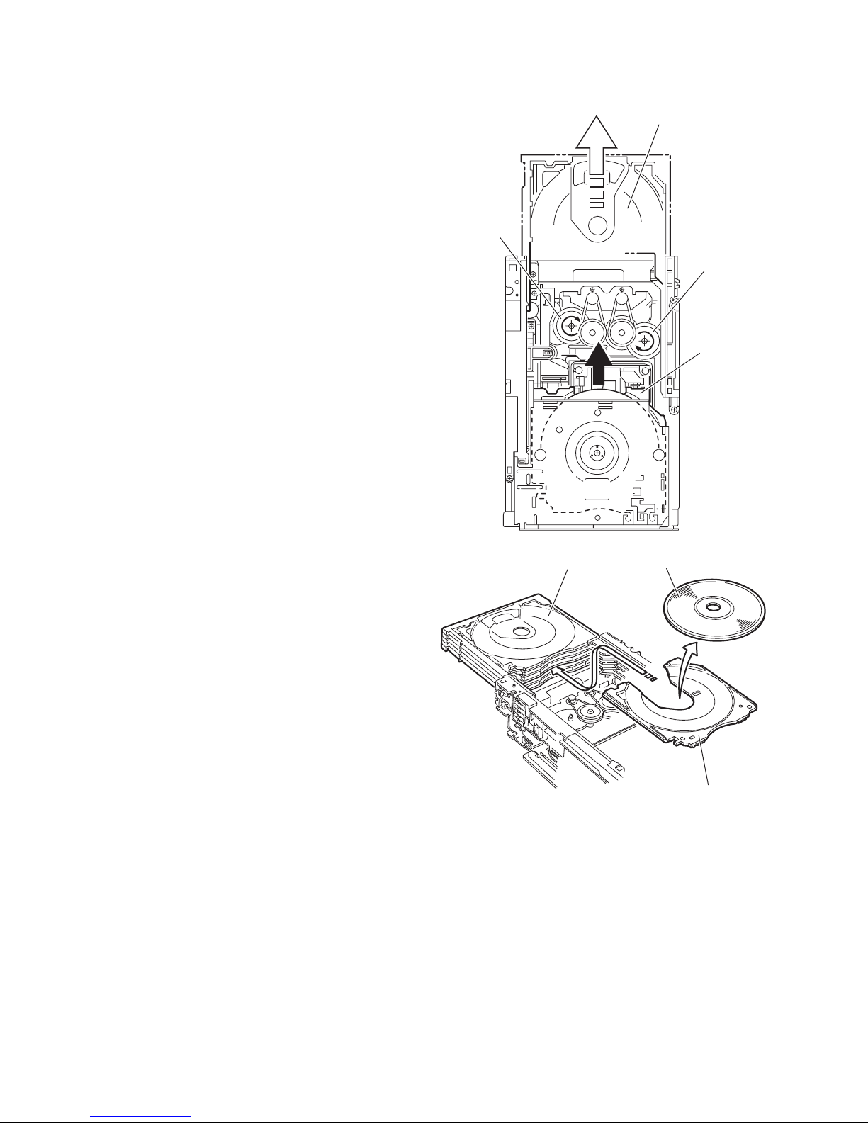
3.2.15 Taking out the disc in the play mode
(See Fig.34 to 37)
Reference:
Refer to "3.3.1 Removing the tray assemblies".
(1) From the top side of the DVD changer mechanism assem-
bly, remove the top cover.
(2) Unlock the tray assemblies and draw out the tray assem-
blies toward the front.
(3) From the top side of the DVD changer mechanism assem-
bly, turn the gear 1 clockwise to move the lifter assembly
upward. (See Fig.34.)
(4) Turn the gear 2 clockwise to move the sub tray remaining
inside the lifter assembly toward the front, then pull out.
(See Fig.34.)
(5) Take out the disc on the sub tray. (See Fig.35.)
(6) After clearing away the disc, insert the sub tray into the
main tray. (See Fig.36.)
Note:
When reattaching the sub tray, move the tray stopper on
the bottom of the main tray in the direction of the arrow
to lock the sub tray certainly. (See Figs.36 and 37.)
(7) Push the tray assembly toward the DVD changer mecha-
nism assembly and reattach.
Tray assembly
Gear 2
Gear 1
Sub tray
Fig.34
Tray assembly
Fig.35
Disc
Sub tray
1-30 (No.MB505)
Page 31

Tray stopper
r
Main tray
Sub tray
Fig.36
Tray stoppe
Fig.37
(No.MB505)1-31
Page 32

SECTION 4
ADJUSTMENT
4.1 ATTENTION IN SERVICE OF DVD SECTION
(1) When pickup, Flash ROM ,DVD module board were changed, initialize EEPROM by all means.
(2) When full initialization was excuted, excute learning with a DVD test disc by all means.
Test disc : VT-501, VT-502
Learning method : It is adjusted automatically by normal playback of a DVD disc.
4.2 Test mode
Item Operation Managemant
Tray lock STOP [key] + DISC 1 EJECT
(Only during Stanby Mode)
Cold start [Remocon key]
STANDBY/ON + ENTER + 10
CLOCK
FAST FORWARDING
FAN ON/OFF Setting STOP [key] + DISC 2 EJECT
VOLUME LARGE
STEP CHANGE
MICON VERSION
DISPLAY
FL ALL SEGMENT
and TEMPERATURE
DATA
DVD test mode STOP [key] + EJECT 5[key]
[Remocon key]
STANDBY/ON + ENTER + 2
(During STANDBY MODE)
[Remocon Key]
STANDBY/ON + ENTER + 1
[Remocon Key]
STANDBY/ON + ENTER + 9
[Remocon Key]
STANDBY/ON + ENTER + >=10
(Hold during AC In)
Loader-Mehca is locked.
EJECT processing isn't done by pushing EJECT key at tray
lock state.
Then display to LOCKED/UNLOCKED.
EJECT 1 is pushed, pushing STOP again, tray lock is off.
Back up to tray locked ON/OFF.
Cold start processing.
After cold start is activated, FL temporary display
COLD' for 2 seconds. Then return to previous display.
To activate cold start AC OFF system, then AC ON again.
Fast Forward Clock (Increase clock counter speed)
Can only be activated after SYSTEM Clock is set
To exit this TEST mode, AC OFF the system, then AC ON
again.
Toggle between FAN switch ON and OFF.
( FANCTRL : L -> H TOGGLE )
This test mode is only effective during STANDBY MODE.
Need to set POUTREG to H when FANCTRL is H.
Test mode exit when system STANDBY -> P.ON
VOLUME CHANGE
VOLUME STEP MAX(40)
-> VOLUME STEP CENTER(20) TOGGLE
Normal Operation TEST mode.
System returns to normal operation after performing VOLUME
CHANGE.
TEMPORARY DISPLAY FOR MICON VERSION (5SEC)
After 5 seconds, return to previous display.
Each key press will toggle temporary display for the following:
SYSCON VERSION -> DVD LSI (BE) VERSION) and DVD
MECHA VERSION
* DVD LSI (BE & FE) VERSION CAN ONLY BEEN DISPLAY
DURING
SYSTEM POWER ON IN DVD MODE (WHEN DVD LSI P.ON)
* IF THERE IS NO INFORMATION FEEDBACK, SYS-CON
WILL DISPLAY
"WAIT" BLINKING 0.5SEC ON & OFF
Actual FL display SYSCOM version "012417-R**" or
"030227-R**"
FL ALL SEGMENT ON (NO BLINK)
Each key press will toggle between FL ALL SEGMENT, TEMP
decimal data and DVD THERMISTOR Temperature data.
Enters DVD-TEST mode.
DVD-TEST mode specification based on DVD-MODULE spec.
To exit DVD-TEST mode, AC OFF the system, then AC ON
again.
For Region Rewrite and DVD-AUDIO Device Key Writing,
refer to Region Rewrite and Device Key Writing section below
for exit procedure.
1-32 (No.MB505)
Page 33

Item Operation Managemant
DVD initialize >>| [key] during DVD test mode DVD module initialized.
FL 8 Segments will display 'INIT' after initialize.
" T xxy v0 " <- " T xxy vw "
Display will return to DVD Test Mode Area display.
( " T xxy vw " )
Press Power key to exit this TEST mode.
To exit this TEST mode, AC OFF the system, then AC ON
again.
DVD region confirm
mode
STOP [key] + EJECT 5[key]
(Hold during AC In)
FL display " T E*0 " (E=Euro) Region*
FL display " T E2 0 " (E=Euro) Region 2
or " TJC10 " (JC=USA/CANADA)Region 1
Tuner test mode [Remocon key]
Standby + enter + 0
eg: V U2 9K " VE 9K " Euro or " VJC 10K " (USA/CANADA)
V: version
U2: A/UF/UN/US
9K: AM STEP SETTING
SAFETY MODE check
by WHAT
STOP + LINE [key]
In standby [after safety trigger]
(A) If safety-cassette deck trigger, FL show : " ACM SAFETY "
(B) If /protect trigger, FL show : "AMP SAFETY"
(C) If /safety-reg trigger, FL show : "REG SAFETY"
(D) If flock trigger, FL show : "FAN SAFETY"
(E) If DVD temperature trigger, FL show : "DVD-SAFETY"
POWER KEY PRESSED to exit
*Note:
1. Other than Device Key Writing & DVD Region Re-write case, other test mode can be exit
by pressing POWER KEY on SET.
2. During any other Test Mode, when POWER KEY is pressed, wait until "POFF OK" displayed
(with Backlight LED off) meaning that DVD Test mode is successfully exit.
3. "POFF OK" Display will be indicated for 5sec only, then it will return to Standby Mode Display
4. After "POFF OK" dsiplay, system is now go back to normal operation mode.
4.3 Other test mode's operation
1. To enter DVD TEST mode,
a. AC POWER OFF
b. Press and hold STOP+DVD5 EJECT/CLOSE keys.
c. AC POWER ON while holding STOP+DVD5 EJECT/CLOSE keys.
d. Sys-con will send the following commands:
(INIT Command, TEST MODE Start)
(MODE STATE REPORT Command, DELIVERY INFO)
(STATUS REQUEST, DESTINATION AND REGION INFO)
(DESTINATION INFO, DESTINATION NUMBER, REGION INFO).
e. DVD Mecha will start in TEST MODE, FL will display:
Txxyvw
xx is the received DESTINATION information. Display as follows:
xx = JC/1U/D/E/2U/3U/UB/UT/4U/UY/EE/UF
y = region number
v = study state information from MECHA-CON (Display Byte3 when Byte7 is "0x09")
w = initialization state from MECHA-CON (Display Byte4 when Byte7 is "0x09".Display blank when Byte4 is "0xFF". )
2. To extie DVD TEST mode,
a. During TEST MODE (except for Device Key write & DVD Region Re-write), press POWER KEY
and wait until "POFF OK" is displayed for 5sec, then system goes into Standby Mode & Backlight LED is off
This means that System now successfully exit the DVD Test Mode & back to normal mode
b. To exit TEST mode for Device Key Write & DVD Region Re-write, first AC OFF,
then AC ON again to return to normal state.
(No.MB505)1-33
Page 34

3. EEPROM INITIALIZATION
(1) NORMAL INITIALIZE
a. During DVD TEST MODE, Press >>| key on remote control to start NORMAL EEPROM INITIALIZATION.
b. Sys-con will send the following command:
c. Mecha will feedback the following information after finish INITIALIZATION:
Status: Byte 0 = 0x00 (NORMAL), Byte 7 = 0x09, Byte 4 = initialization state
d. When received status, FL will display:
Txxyvw
w = initialization state from MECHA-CON (Display Byte4 when Byte7 is "0x09".Display blank when Byte4 is "0xFF". )
(2) FULL INITIALIZE
a. During DVD TEST MODE, STOP key on set 2 seconds control to start FULL EEPROM INITIALIZATION.
b. Sys-con will send the following command:
c. Mecha will feedback the following information after finish INITIALIZATION:
Status: Byte 0 = 0x00 (NORMAL), Byte 7 = 0x09, Byte 4 = initialization state
d. When received status, FL will display:
Txxyvw
w = initialization state from MECHA-CON (Display Byte4 when Byte7 is "0x09".Display blank when Byte4 is "0xFF". )
4. DEVICE KEY CHECKSUM DISPLAY
a. During DESTINATION INFO display screen (1), press MENU key to enter DEVICE KEY CHECKSUM display
(TEST MODE, MODE STATE, CHECK MODE)
(DEVICE KEY CHECKSUM)
FL will display (Example):
XXXXXX X DISPLAY BOTH CPPM AND CPRMX
5. DVD CHECK MODES
a. Press MENU key again to enter CHECK MODE.
(TEST MODE, MODE STATE, CHECK MODE)
FL Display:
HCEKC
Press '1' key on REMOTE CONTROL to START PLAYBACK.
FL Display:
ALPYABKC
Press '2' key on REMOTE CONTROL to perform SEARCH TNO+1
FL Display:
BOW B E (2 seconds)L
Status: 00(NORMAL) XX XX cc cc jj jj
ccccjj j cccc: Byte 0 = 0x00, Byte 7 = 0x00, Byte 3,4 ¨DISPLAY
j
jjjj: Byte 0 = 0x00, Byte 7 = 0x00, Byte 5,6 ¨DISPLAY
Press '3' key on REMOTE CONTROL to perform SEARCH TNO-1
FL Display:
HCEKC
Press '4' key on REMOTE CONTROL to light up CD_LD and display laser current.
FL Display:
LDC D R (2 seconds)
LS
Status: 00(NORMAL) XX XX cc cc jj jj
ccccjj j cccc: Byte 0 = 0x00, Byte 7 = 0x00, Byte 3,4 ¨DISPLAY
j
Press '5' key on REMOTE CONTROL to light up DVD_LD and display laser current.
1-34 (No.MB505)
(Static)
jjjj: Byte 0 = 0x00, Byte 7 = 0x00, Byte 5,6 ¨DISPLAY
Page 35

FL Display:
Status: 00(NORMAL) XX XX cc cc jj jj
Press '6' key on REMOTE CONTROL to enter DVD x 2 JITTER MEASUREMENT MODE
FL Display:
Status: 00(NORMAL) XX XX cc cc jj jj
Press '7' key on REMOTE CONTROL to view EEPROM (MECHA) content in -1 address step.
FL Display:
Status: 00(NORMAL) XX XX cc cc jj jj
Press '8' key on REMOTE CONTROL to view EEPROM (MECHA) content in +1 address step.
FL Display:
Status: 00(NORMAL) XX XX cc cc jj jj
LDC D R (2 seconds)
ccccjj j cccc: Byte 0 = 0x00, Byte 7 = 0x00, Byte 3,4 ¨DISPLAY
LS
j
(Static)
jjjj: Byte 0 = 0x00, Byte 7 = 0x00, Byte 5,6 ¨DISPLAY
TIJ X (2 seconds)
1
ccccjjjj
(Static)
cccc: Byte 0 = 0x00, Byte 7 = 0x00, Byte 3,4 ¨DISPLAY
jjjj: Byte 0 = 0x00, Byte 7 = 0x00, Byte 5,6 ¨DISPLAY
PEE B D (2 seconds)
ccccjjjj
W
(Static)
cccc: Byte 0 = 0x00, Byte 7 = 0x00, Byte 3,4 ¨DISPLAY
jjjj: Byte 0 = 0x00, Byte 7 = 0x00, Byte 5,6 ¨DISPLAY
PEE F D (2 seconds)
ccccjjjj
W
(Static)
Byte 3,4 ¨DISPLAY
jjjj: Byte 0 = 0x00, Byte 7 = 0x00, Byte 5,6 ¨DISPLAY
Press '9' key on REMOTE CONTROL to perform SEARCH DVD_SL DESIGNATED POSITION and
JITTER MEASUREMENT
FL Display:
Status: 00(NORMAL) XX XX cc cc jj jj
Press '10' key on REMOTE CONTROL to perform SEARCH DVD_DL PARALLEL DISC DESIGNATED
POSITION and JITTER MEASUREMENT
FL Display:
Status: 00(NORMAL) XX XX cc cc jj jj
Press '0' key on REMOTE CONTROL to perform monitor output.
FL Display:
Status: 00(NORMAL) XX XX cc cc jj jj
MPET (2 seconds)
ccccjjjj
(Static)
D-DLVD (2 seconds)
ccccjjjj
(Static)
NIT ROOM (2 seconds)
ccccjjjj
(Static)
cccc: Byte 0 = 0x00, Byte 7 = 0x00, Byte 3,4 ¨DISPLAY
jjjj: Byte 0 = 0x00, Byte 7 = 0x00, Byte 5,6 ¨DISPLAY
cccc: Byte 0 = 0x00, Byte 7 = 0x00, Byte 3,4 ¨DISPLAY
jjjj: Byte 0 = 0x00, Byte 7 = 0x00, Byte 5,6 ¨DISPLAY
cccc: Byte 0 = 0x00, Byte 7 = 0x00, Byte 3,4 ¨DISPLAY
jjjj: Byte 0 = 0x00, Byte 7 = 0x00, Byte 5,6 ¨DISPLAY
Press '>=10' key to INITIALIZE EEPROM (MECHA)
FL Display:
ITNI (2 seconds)
Press PLAY key on REMOTE CONTROL to start PLAYING and obtain LASER CURRENT and JITTER value.
(No.MB505)1-35
Page 36

FL Display:
RJ TISL (2 seconds)
Status: 00(NORMAL) XX XX cc cc jj jj
ccccjjjj
(Static)
cccc: Byte 0 = 0x00, Byte 7 = 0x00, Byte 3,4 ¨DISPLAY
jjjj: Byte 0 = 0x00, Byte 7 = 0x00, Byte 5,6 ¨DISPLAY
Press STOP key on REMOTE CONTROL to stop JITTER measurement.
FL display remains.
FFFF FFFF
(Static)
b. During CHECK mode, at any time press MENU key to exit CHECK mode and return to starting screen of DVD
TEST MODE.
* During TEST mode,at press POWER key send POWER OFF command to MECHA-CON and if poweroff permit
flag is 1, display "POFF OK"
FF KOOP
1-36 (No.MB505)
Page 37

SECTION 5
TROUBLESHOOTING
This service manual does not describe TROUBLESHOOTING.
(No.MB505)1-37
Page 38

Victor Company of Japan, Limited
Audio/Video Systems Category 10-1,1chome,Ohwatari-machi,Maebashi-city,371-8543,Japan
(No.MB505)
Printed in Japan
VPT
 Loading...