


 Loading...
DVD DIGITAL CINEMA SYSTEM
TH-V70
Consists of XV-THV70, SP-PWV70, SP-XSV70, and SP-XCV70
|
|
|
|
TV |
|
AUDIO |
|
AUX |
FM/AM |
|
|
VCR |
|
|
AUDIO |
ANGLE |
SUBTITLE |
DECODE |
||
|
RETURN |
DIGEST |
ZOOM |
VFP |
||
|
|
|
|
+ |
|
|
|
TOP MENU |
MENU |
ZOOM |
PROGRESSIVE |
||
|
|
|
|
– |
|
SOUND |
|
CONTROL |
– SUBWOOFER + |
EFFECT |
|||
|
VCR |
|
1 |
2 |
|
3 |
|
|
– |
CENTER |
+ |
TEST |
|
|
TV |
|
4 |
5 |
|
6 |
D V D D I G I T A L C I N E M A S Y S T E M |
SLEEP |
– |
REAR-L |
+ |
|
|
T H - V 7 0 |
|
– |
7 |
8 |
+ |
9 |
|
SETTING |
REAR-R |
|
|||
|
|
|
10 |
0 |
|
+10 |
|
TV RETURN |
FM MODE |
100+ |
|||
|
ON |
|
|
|
|
|
|
SCREEN |
|
|
|
|
AUDIO/ |
|
|
|
|
|
|
TV/VCR |
|
|
|
|
|
|
CATV/DBS |
|
CHOICE |
|
ENTER |
|
SURROUND |
|
|
|
|
|
|
MODE |
|
|
TV VOL |
CHANNEL |
|
VOLUME |
||
|
|
TV/VIDEO |
MUTING |
|
||
|
1 |
|
|
|
|
¡ |
|
/REW |
|
PLAY |
|
FF/ |
|
|
DOWN |
|
TUNING |
|
UP |
|
|
REC |
|
STOP |
|
PAUSE |
|
|
MEMORY |
|
|
|
|
STROBE |
|
|
|
DIMMER |
|
|
|
|
|
RM–STHV70U |
|
|||
|
DVD CINEMA SYSTEM |
|||||
INSTRUCTIONS
For Customer Use:
Enter below the Model No. and Serial No. which are located either on the rear, bottom or side of the cabinet. Retain this information for future reference.
Model No.
Serial No.
LVT0865-015A
[A]

Warnings, Cautions and Others
Caution ––  button! (XV-THV70)
Disconnect the mains plug to shut the power off completely (the goes off).
The  button in any position does not disconnect the mains line.
•When the system is on standby, the  lights red.
•When the system is turned on, the operation lamps light red.
The power can be remote controlled.
CAUTION
To reduce the risk of electrical shocks, fire, etc.:
1.Do not remove screws, covers or cabinet.
2.Do not expose this appliance to rain or moisture.
CAUTION
•Do not block the ventilation openings or holes.
(If the ventilation openings or holes are blocked by a newspaper or cloth, etc., the heat may not be able to get out.)
•Do not place any naked flame sources, such as lighted candles, on the apparatus.
•When discarding batteries, environmental problems must be considered and local rules or laws governing the disposal of these batteries must be followed strictly.
•Do not expose this apparatus to rain, moisture, dripping or splashing and that no objects filled with liquids, such as vases, shall be placed on the apparatus.
G-1
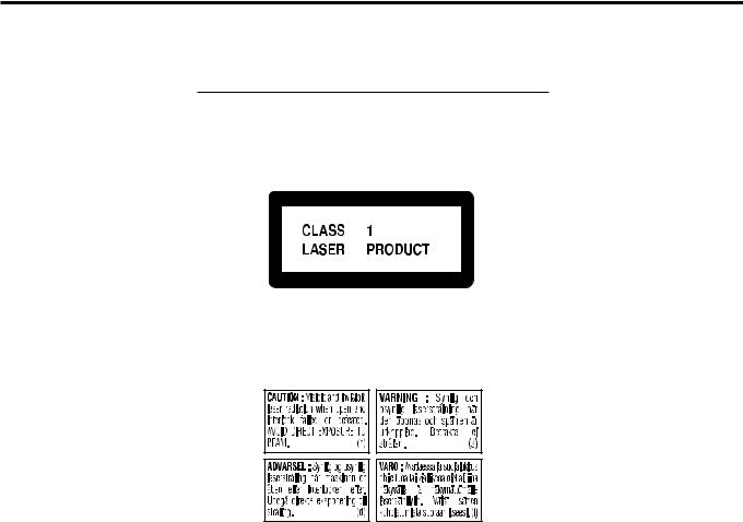
IMPORTANT FOR LASER PRODUCTS
REPRODUCTION OF LABELS
1 CLASSIFICATION LABEL, PLACED ON EXTERIOR SURFACE
2 WARNING LABEL, PLACED INSIDE THE UNIT
1.CLASS 1 LASER PRODUCT
2.DANGER: Visible and invisible laser radiation when open and interlock failed or defeated. Avoid direct exposure to beam.
3.CAUTION: Do not open the top cover. There are no user serviceable parts inside the Unit; leave all servicing to qualified service personnel.
G-2
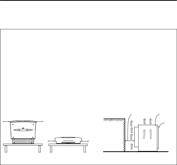
Caution: Proper Ventilation
To avoid risk of electric shock and fire and to protect from damage, locate the apparatus as follows:
Top: No obstructions and open spacing.
Sides/Front/Back: No obstructions should be placed in the areas
|
shown by the dimensions below. |
Bottom: |
Place on the level surface. Maintain adequate air |
|
path for ventilation by placing on a stand with a |
|
height of 10 cm more. |
Front view
1 cm |
XV-THV70 |
1 cm |
XV-THV70
1 cm  1 cm
1 cm
Side view
15 cm |
SP-PWV70 |
|
Front |
Wall or |
|
obstructions |
|
|
Floor |
G-3

Table of Contents
Introduction ........................................... |
2 |
Notes on handling ............................................................. |
2 |
Checking the supplied accessories ................................. |
2 |
Names of parts and controls .................. |
3 |
About discs ............................................ |
6 |
Playable disc types ............................................................ |
6 |
Disc structure ..................................................................... |
7 |
Playback Control function (PBC) ..................................... |
7 |
Getting started ...................................... |
8 |
Setting the DISP.SET selector .......................................... |
8 |
When placing the center unit vertically ........................... |
9 |
Connections ..................................................................... |
10 |
Connecting a TV ............................................................... |
10 |
Connecting the FM and AM antennas .............................. |
11 |
Connecting the powered subwoofer ................................ |
12 |
Connecting the satellite speakers .................................... |
12 |
Connecting to an analog component ............................... |
14 |
Connecting to a digital component .................................. |
14 |
Connecting the power cord .............................................. |
15 |
Installing the equipment on the wall .............................. |
16 |
When attaching the rear speakers to a wall ..................... |
16 |
When attaching the AM loop antenna to a wall ................ |
16 |
When attaching the center unit to a wall .......................... |
17 |
Using the remote control ................................................ |
19 |
Putting batteries in the remote control .............................. |
19 |
Operating the system from the remote control ................. |
19 |
Using the remote control for TV operations ...................... |
20 |
Basic operations .................................. |
21 |
Turning on/off the system ............................................... |
21 |
Selecting the source to play ........................................... |
22 |
Adjusting volume ............................................................. |
22 |
Turning off the sound temporarily ................................. |
23 |
Adjusting the brightness ................................................ |
23 |
Turning off the power with the timer .............................. |
24 |
Setting the subwoofer ..................................................... |
24 |
Changing the decode mode ............................................ |
25 |
Changing the scan mode ................................................ |
26 |
Basic playback .................................... |
27 |
Inserting and removing a disc ........................................ |
27 |
Stopping playback temporarily ...................................... |
28 |
Stopping playback completely ....................................... |
29 |
Moving back the playback position during DVD |
|
playback ...................................................................... |
29 |
Searching for a particular point ...................................... |
30 |
Locating the beginning of a desired chapter or track |
.. 30 |
Locating a desired selection using Number buttons ... |
30 |
Tuner operations .................................. |
31 |
Setting the AM tuner interval spacing ........................... |
31 |
Tuning in to stations manually ....................................... |
31 |
Using preset tuning ......................................................... |
31 |
Selecting the FM reception mode .................................. |
32 |
Reducing the noise of AM broadcast............................. |
32 |
Creating the realistic sound fields......... |
33 |
Dolby Surround ................................................................. |
33 |
DTS Digital Surround ........................................................ |
33 |
DAP modes ...................................................................... |
34 |
All Channel Stereo ............................................................ |
34 |
Selecting the surround mode ......................................... |
35 |
Using Dolby Pro Logic II, Dolby Digital and DTS Digital |
|
Surround ..................................................................... |
35 |
Using DAP Modes and All Channel Stereo .................... |
36 |
Advanced operations ........................... |
37 |
Using the on-screen bar .................................................. |
37 |
Showing the on-screen bar .............................................. |
37 |
Basic operation through the on-screen bar ...................... |
38 |
Changing the time information ......................................... |
38 |
Locating a desired scene from the disc menu .............. |
39 |
Locating a desired scene from the DVD menu ................ |
39 |
Locating a desired scene from the Video CD/SVCD menu |
|
with PBC ..................................................................... |
39 |
Selecting a view angle of DVD ........................................ |
40 |
Selecting a view angle ..................................................... |
40 |
Showing all view angles on the TV ................................... |
41 |
Changing the subtitle languages and audio languages ..... |
41 |
Selecting the subtitle language ........................................ |
41 |
Selecting the audio language .......................................... |
42 |
Selecting the audio channel ............................................. |
43 |
Playing from a specified position on a disc .................. |
44 |
Locating a desired chapter from the on-screen bar ........ |
44 |
Locating a desired position by specifying the time .......... |
45 |
Locating a desired scene from the digest display ........... |
45 |
Special picture playback ................................................. |
46 |
Frame-by-frame playback ................................................ |
46 |
Showing continuous still pictures ..................................... |
46 |
Playing back in slow-motion ............................................. |
47 |
Zooming in/out .................................................................. |
47 |
Changing the VFP setting ................................................. |
48 |
Changing the track order ................................................ |
49 |
Playing back in the desired order .................................... |
49 |
Playing back tracks in random order ............................... |
49 |
Repeat playback ............................................................... |
50 |
Repeating a current title, chapter, or all tracks ................ |
50 |
Repeating a desired part ................................................. |
50 |
MP3 disc playback .............................. |
51 |
JPEG disc playback .............................. |
53 |
Setting DVD preferences ...................... |
55 |
Using the choice menus.................................................. |
55 |
Choice menus .................................................................. |
55 |
Basic procedure through the choice menus ...................... |
56 |
LANGUAGE menu ............................................................ |
57 |
PICTURE menu ................................................................ |
58 |
AUDIO menu ..................................................................... |
59 |
SPK. SETTING menu ....................................................... |
60 |
OTHERS menu ................................................................ |
62 |
Restricting playback by Parental Lock .......................... |
63 |
Setting Parental Lock ........................................................ |
63 |
Changing the setting of Parental Lock ............................. |
64 |
Releasing Parental Lock temporarily ................................ |
64 |
Setting the system through the display |
|
window ........................................... |
66 |
AV COMPU LINK remote control system 67 |
|
Operating other manufacturers’ video |
|
equipment ....................................... |
69 |
Using the remote control for CATV converter or DBS |
|
tuner operations ......................................................... |
69 |
Using the remote control for VCR .................................. |
70 |
Maintenance ........................................ |
71 |
Troubleshooting ................................... |
72 |
Glossary .............................................. |
75 |
Specifications ....................................... |
76 |
1
Introduction
Notes on handling
Important cautions
Installation of the system
•Select a place which is level, dry and neither too hot nor too cold between 5°C and 35°C (41°F and 95°F).
•Leave sufficient distance between the system and the TV.
•Do not use the system in a place subject to vibrations.
Power cord
•Do not handle the power cord with wet hands!
•A small amount of power (1.7 watts) is always consumed while the power cord is connected to the wall outlet (the center unit only).
•When unplugging the power cord from the wall outlet, always pull the plug, not the power cord.
To prevent malfunction of the system
•There are no user-serviceable parts inside. If anything goes wrong, unplug the power cord and consult your dealer.
•Do not insert any metallic object into the system.
•Do not apply any shock to the moving panel when it is open.
•An 8 cm disc cannot be played back in this system. (Do not attempt to insert an 8 cm disc using an adaptor. Doing so will damage the system.)
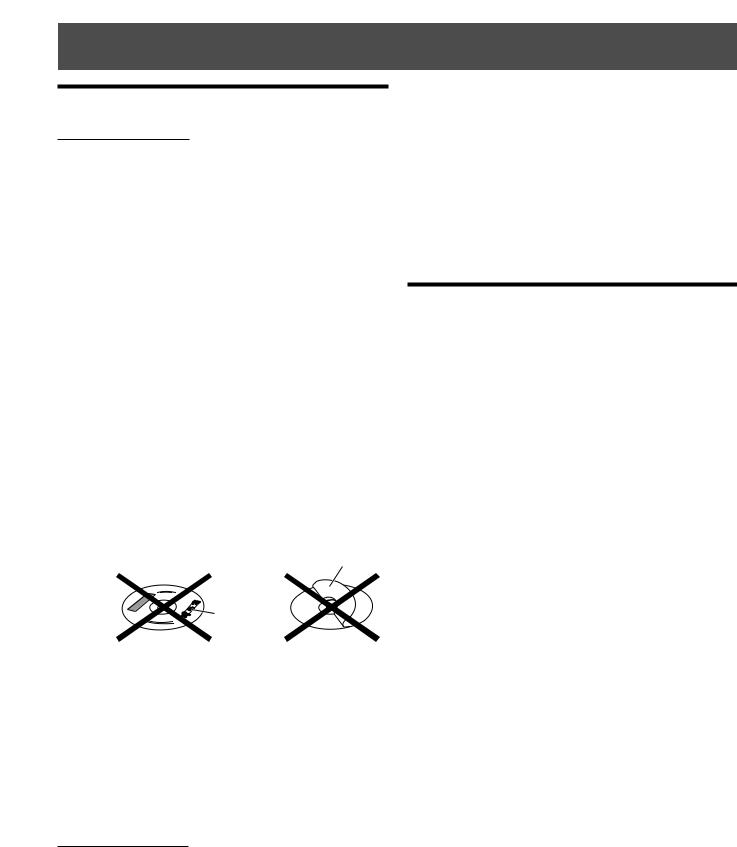
•Do not use any non-standard shape disc (like a heart, flower, or credit card, etc.) available on the market, because it may damage the system.
•Do not use a disc with tape, stickers, or paste on it, because damage to the system may result.
Label sticker
Sticker 
Paste
Note about copyright laws
Check the copyright laws in your country before recording from DVD Video, Super Video CD (SVCD), Video CD, and Audio CD discs. Recording of copyrighted material may infringe copyright laws.
Note about the copyguard system
The DVD Video discs are protected by the copyguard system. When you connect the system to your VCR directly, the copyguard system activates and the picture may not be played back correctly.
Safety precautions
Avoid moisture, water and dust
Do not place the system in moist or dusty places.
Avoid high temperatures
Do not expose the system to direct sunlight or do not place it near a heating device.
When you are away
When away on travel or otherwise for an extended period of time, remove the plug from the wall outlet.
Do not block the vents
Blocking the vents may damage the system.
Care of the cabinet
When cleaning the system, use a soft cloth and follow the relevant instructions on the use of chemically-coated cloths. Do not use benzene, thinner or other organic solvents including disinfectants. These may cause deformation or discoloring.
• Do not clean the moving panel when it is open.
If water gets inside the system
Turn the system off and remove the plug from the wall outlet, then call the store where you made your purchase. Using the system in this state may cause a fire or electrical shock.
Checking the supplied accessories
Check to be sure you have all of the supplied accessories. The number in the parentheses is the quantity of the pieces supplied.
If anything is missing, contact your dealer immediately.
•Remote control (1)
•Batteries (2)
•Stand (1) (for the center unit)
•Legs (2) (for the stand)
•FM antenna (1)
•AM loop antenna (1)
•Power cord (1)
•System cord (1)
•Video cord (1)
•AV COMPULINK cord (1)
•Speaker cords
5 m (3): For the left front speaker, right front speaker, and center speaker
10 m (2): For the left rear speaker and right rear speaker (The length of the above speaker cords are approximate.)
•Speaker wall brackets (2)
•Screws
For the stand (1)
For the speaker wall brackets (2)
•Paper pattern (1) (for attaching the center unit to a wall)
2
Names of parts and controls
See pages in the parentheses for details.
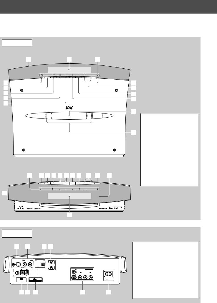
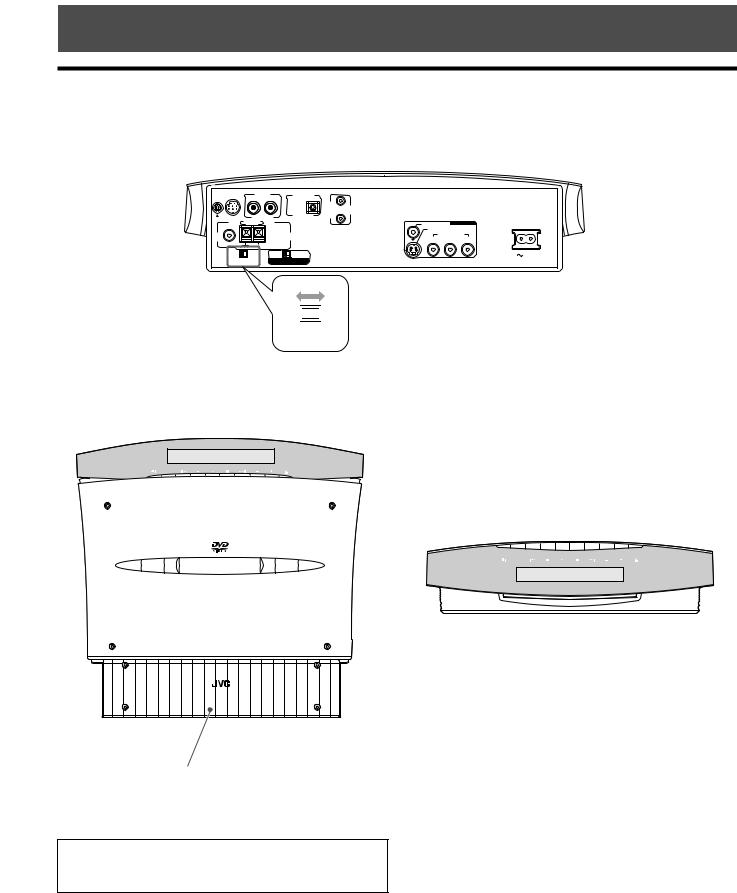
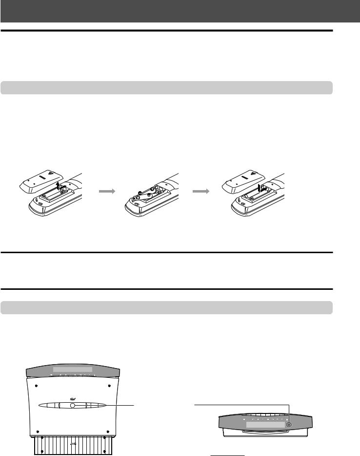
Center unit
Front panel
Placed vertically (with DISP.SET set to “V”)
1 |
2 |
3 |
SOURCE |
|
VOL |
4 |
|
9 |
5 |
|
p |
6 |
|
q |
7 |
|
w |
8 |
|
|
e
D V D D I G I T A L C I N E M A S Y S T E M
T H - V 7 0
r
Placed horizontally (with DISP.SET set to “H”)
3 4 5 6 7 8 w q p 9 e |
SOURCE |
VOL |
1
COMPACT
SUPER VIDEO
Front panel
1 Moving panel (21)
2 Display window
3 Button name indicators (21)
4  button (21)
5 SOURCE button (22)
6 4 (reverse skip) button (30)
7 7 (stop) button (29)
8 3 (play) button (29)
9 0 (open/close) button (27) p VOLUME +/– buttons (22)
q ¢ (forward skip) button (30) w 8 (pause) button (28, 46)
e Remote sensor (19) r Illumination lamps (21)
2
Rear panel
1 |
2 |
|
3 4 |
|
|
|
TO SP-PWV70 |
AUX IN |
|
DIGITAL IN |
|
|
|
|
|
|
|
AV |
|
|
|
|
|
|
COMPU |
|
|
|
R |
L |
OPTICAL |
LINK |
|
|
FM 75 |
AM LOOP |
|
|
VIDEO |
VIDEO OUT |
|
|
|
|
S-VIDEO |
|
||
|
|
|
|
|
||
|
|
ANTENNA |
Y |
COMPONENT |
PR |
|
COAXIAL |
|
|
|
PB |
||
AM EXT |
|
|
|
|
|
|
|
|
|
|
|
|
|
H |
V |
PAL |
NTSC |
|
|
AC IN |
DISP.SET |
VIDEO OUT SELECT |
|
|
|
||
5 6 7 |
8 |
9 |
Rear panel
1 System cord CONNECTOR (12)
2 AUX IN jacks (14)
3 DIGITAL IN jack (14)
4 AV COMPU LINK jacks (67)
5 DISP.SET (Display set) selector (8)
6 ANTENNA terminals (11)
7 VIDEO OUT SELECT switch (10)
8 VIDEO OUT jacks (10)
VIDEO, S-VIDEO, COMPONENT (Y, PB, PR)
9 Ó AC IN socket (15)
3
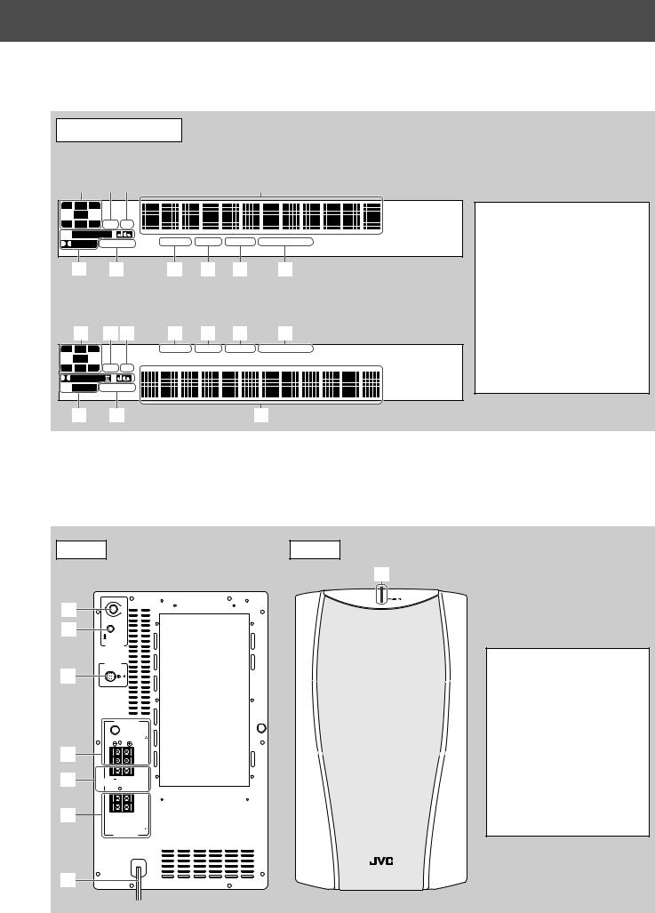
Display window
Placed vertically (with DISP.SET set to “V”)*
1 |
|
2 |
|
3 |
|
4 |
L C R
LFE |
LS S RS DSP CH
 PRO LOGIC
DIGITAL SURROUND |
RESUME TUNED STEREO AUTO MUTING |
5 |
6 |
7 |
8 |
9 |
p |
Placed horizontally (with DISP.SET set to “H”)
1 |
2 3 |
7 |
8 |
9 |
p |
L C R |
RESUME TUNED STEREO AUTO MUTING |
LFE
LS |
S RS DSP CH |
|
PRO LOGIC |
 DIGITAL SURROUND
Display window
1 Signal indicators (34)
2 DSP indicator (34)
3 CH indicator (32)
4 Main display
5• PRO LOGIC II indicator (33)
•Digital signal format indicators (33)
DOLBY DIGITAL and DTS
6 SURROUND indicator (36)
7 RESUME indicator (29)
8 TUNED indicator (31)
9 STEREO indicator (31, 32) p AUTO MUTING indicator (32)
5 |
6 |
4 |
*This manual explains operations using the illustrations of the display window that are shown when the center unit is placed vertically (the DISP.SET selector is set to “V”).
Powered subwoofer
Rear |
Front |
|
8 |
|
VOLUME |
1 |
MAX |
MIN |
2
PHASE
REVERSE
NORMAL
SUB WOOFER
C O N N E C T O R
F R O M X V - T H V 7 0
3
|
F R O N T S P E A K E R S |
|
CAUTION : |
|
S P E A K E R I M P E D A N C E 4~16 |
4 |
LEFT |
|
RIGHT |
5CENTER 
 CAUTION :S P E A K E R I M P E D A N C ESPEAKER
4~16
LEFT
RIGHT
6


CAUTION :
S P E A K E R I M P E D A N C E 4~16
REAR S P E A K E R S
Powered subwoofer
1 VOLUME knob (24)
2 PHASE button (24)
3 System cord CONNECTOR
(12)
4FRONT SPEAKERS terminals (13)
5 CENTER SPEAKER terminals (13)
6REAR SPEAKERS terminals (13)
7 Power cord (15)
8 POWER ON lamp (22)
7
4
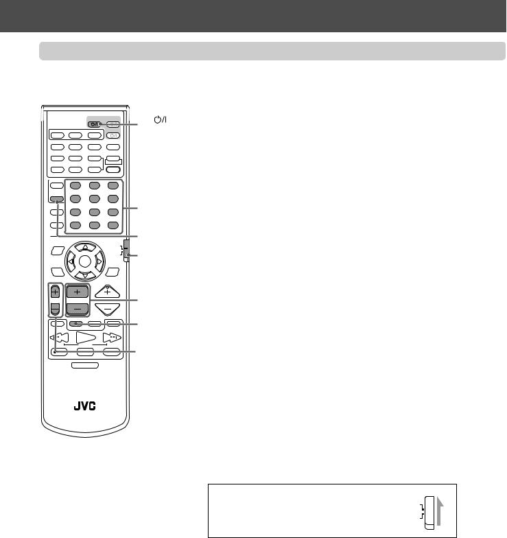
Names of parts and controls
Remote control
o
|
|
|
|
|
TV |
AUDIO |
; |
|
1 |
|
|
|
|
|
|
||
AUX |
FM/AM |
|
|
VCR |
a |
|||
2 |
|
|
|
|
|
|
||
AUDIO |
ANGLE SUBTITLE |
DECODE |
s |
|||||
3 |
||||||||
|
|
|
|
|
|
d |
||
4 |
RETURN |
DIGEST |
ZOOM |
VFP |
||||
5 |
|
|
|
|
+ |
|
f |
|
TOP MENU |
MENU |
ZOOM |
PROGRESSIVE |
|||||
6 |
|
g |
||||||
|
|
|
|
– |
SOUND |
|||
7 |
CONTROL |
– SUBWOOFER + |
EFFECT |
h |
||||
8 |
VCR |
1 |
|
|
2 |
3 |
|
|
|
– |
CENTER |
+ |
TEST |
|
|||
|
TV |
4 |
|
|
5 |
6 |
|
|
|
SLEEP |
– |
REAR-L |
+ |
|
j |
||
9 |
|
|
||||||
|
7 |
|
|
8 |
9 |
|
||
p |
SETTING |
– |
REAR-R |
+ |
|
|
||
|
10 |
|
|
0 |
+10 |
|
||
|
TV RETURN |
FM MODE |
100+ |
|
||||
|
ON |
|
|
|
|
|
|
|
|
SCREEN |
|
|
|
|
AUDIO/ |
|
|
q |
|
|
|
|
|
TV/VCR |
k |
|
|
|
|
|
|
CATV/DBS |
|||
|
|
|
|
|
|
|||
w |
CHOICE |
|
ENTER |
|
SURROUND |
|
||
|
|
|
|
|
MODE |
|
||
e |
|
|
|
|
|
|
l |
|
r |
|
|
|
|
|
|
|
|
t |
TV VOL |
CHANNEL |
|
VOLUME |
/ |
|||
y |
1 |
TV/VIDEO |
MUTING |
¡ |
z |
|||
|
|
|
|
|
|
|||
u |
/REW |
|
PLAY |
|
FF/ |
|
||
|
|
|
|
|||||
|
DOWN |
|
TUNING |
|
UP |
|
||
|
REC |
|
STOP |
|
PAUSE |
|
||
|
MEMORY |
|
|
|
|
STROBE |
|
|
i |
DIMMER |
|
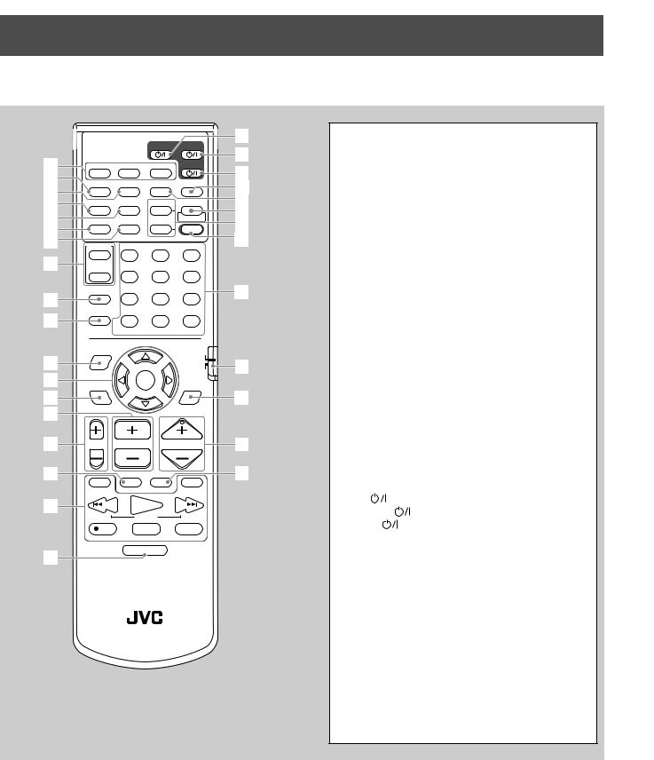
RM–STHV70U
DVD CINEMA SYSTEM
Remote control
1 Source selecting buttons (22) AUX, FM/AM, DVD
2 AUDIO button (42, 43)
3 ANGLE button (40, 41)
4 RETURN button (39)
5 DIGEST button (45)
6 TOP MENU button (39)
7 MENU button (39, 54)
8CONTROL buttons VCR (70), TV (20)
9 SLEEP button (24) p SETTING button (66)
q ON SCREEN button (37)
w Cursor 2/3/5/∞ and ENTER buttons e CHOICE button (56, 63)
r CHANNEL +/– buttons (20, 69, 70) t TV VOL +/– buttons (20)
y TV/VIDEO button (20)
uOperating buttons 1, ¡ (30, 47)
4/REW (TUNING DOWN) (30, 31, 51, 53) PLAY (29, 46, 51, 53)
FF/¢ (TUNING UP) (30, 31, 51, 53) ÷ REC (MEMORY) (31, 70)
STOP (29, 51, 53)
PAUSE (STROBE) (28, 46, 51, 53) i DIMMER button (23)
o TV |
button (20, 69) |
; AUDIO |
button (21) |
a VCR |
button (70) |
s DECODE button (25) d SUBTITLE button (41)
f VFP (PROGRESSIVE) button (26, 48) g ZOOM +/– buttons (47, 53)
h SOUND button (35, 36)
j• Number buttons
•Sound setting buttons (24, 35, 36) SUBWOOFER +/–, CENTER +/–, REAR-L +/–, REAR-R +/–
•EFFECT button (36)
•TEST button (35)
•FM MODE button (32)
k Remote control mode selector l SURROUND MODE button (35) / VOLUME +/– buttons (22)
z MUTING button (23)
5
About discs
Playable disc types
This system has been designed to play back the following discs:
DVD Video, Video CD, Super Video CD (SVCD), Audio CD, CD-R, and CD-RW.
•This system can also play back MP3 and JPEG files recorded on CD-Rs and CD-RWs. For in-depth information about MP3, see “MP3 disc playback” on page 51, and about JPEG, see “JPEG disc playback” on page 53.
•We refer to DVD Video as DVD in this manual.
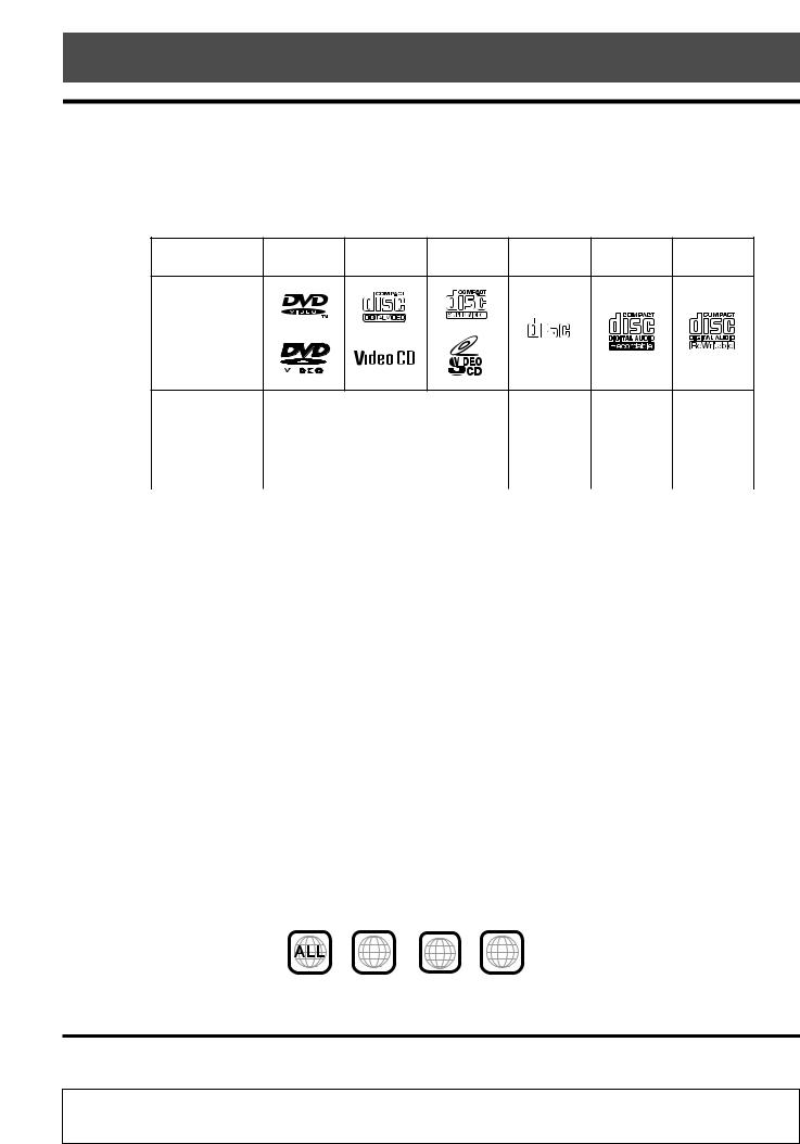
Discs you can play:
Disc Type |
DVD |
Video CD |
SVCD |
Audio CD |
CD-R |
CD-RW |
COMPACT
Mark (Logo)
DIGITAL AUDIO
|
|
|
|
|
|
|
|
|
|
|
|
|
|
|
|
|
|
|
|
|
Video Format |
|
|
|
|
NTSC/PAL |
|
|
|
|
|
|
|
|
|
||||||
|
|
|
|
|
|
|
|
|
|
|
|
|
||||||||
|
|
|
|
|
|
|
|
|
|
|
|
|
||||||||
|
|
|
||||||||||||||||||
|
|
|
|
|
|
|
|
|
|
|
|
|
|
|
|
|
|
|
|
|
Region Code |
4 |
|
|
|
|
|
|
|
|
|
|
|
|
|
|
|
|
|
|
|
Number* |
ALL |
|
|
|
|
|
|
|
|
|
|
|
|
|
|
|
|
|||
|
|
|
|
|
|
|
|
|
|
|
|
|
|
|
|
|
|
|
|
|
•The following discs cannot be played back:
–DVD Audio, DVD-ROM, DVD-RAM, DVD-R, DVD-RW, CD-ROM, CD-I (CD-I Ready), Photo CD, etc. Playing back these discs will generate noise and damage the speakers.
–8 cm disc
An 8 cm disc cannot be played back in this system. (Do not attempt to insert an 8 cm disc using an adaptor. Doing so will damage the system.)
•On some DVD, Video CD, or SVCD discs, their actual operations may be different from what is explained in this
manual. This is due to the disc programming and disc structure, but not a malfunction of this system.
•Notes on CD-R and CD-RW
–User-edited CD-Rs (Recordable) and CD-RWs (Rewritable) can be played back only if they are already “finalized.”
–The system can play back CD-Rs or CD-RWs recorded on a personal computer if they have been recorded in the audio CD format.
The system can also play back CD-Rs or CD-RWs if MP3 files or JPEG files are recorded on them.
However, they may not be played back because of their disc characteristics, recording conditions, or damage or stain on them.
Especially, the configuration and characteristics of an MP3 disc or a JPEG disc is determined by the writing (encoding) software and hardware used for recording. Therefore, due to the software and hardware used, the following symptoms may occur:
•Some discs may not be played back.
•Some tracks on an MP3 disc are skipped and may not be played back normally.
•Some files on a JPEG disc may be played back distortedly.
–Before playing back CD-Rs or CD-RWs, read their instructions or cautions carefully.
–CD-RWs may require a longer readout time. This is caused by the fact that the reflectance of CD-RWs is lower than for regular CDs.
*Note on Region Code
DVD players and DVDs have their own Region Code numbers. This system can play back only DVDs recorded with the color system of NTSC or PAL whose Region Code numbers include “4.”
Examples: |
4 |
4 5 |
2 |
3 |
|
4 |
5 |
||||
|
|
|
If a DVD with the improper Region Code numbers is loaded, “REGION CODE ERROR” appears on the display and playback cannot start.
IMPORTANT: Before playing a disc, make sure of the following....
•Check the connection with the TV.
•Turn on the TV and select the correct input mode on the TV to view the pictures or on-screen indications on the TV screen.
•For DVD playback, you can change the initial setting to your preference. (See pages 55 to 65.)
If  appears on the TV screen when pressing a button, the disc cannot accept an operation you have tried to do, or information required for that operation is not recorded on the disc.
NOTICE: In some cases, without showing  , operations will not be accepted.
6
About discs
Disc structure
A DVD Video disc consists of “titles,” and each title may be divided into some “chapters.” (See Example 1.)
For example, if a DVD disc contains some movies, each movie may have its own title number, and it may be further divided into some chapters.
On the other hand, a Video CD, SVCD, and Audio CD consist of “tracks.” (See Example 2.)
In general, each track has its own track number. (On some discs, each track may also be divided by Indexes.)
Example 1: DVD |
Example 2 : Video CD/SVCD/Audio CD |
Playback Control function (PBC)
The Playback Control function allows you to enjoy menu-driven operation and high-resolution still images which have a resolution four times greater than moving pictures.
• High-resolution still image display
You can display high-quality images four times clearer than moving pictures.
• Menu-driven playback
A selection menu is displayed when you start playing a Video CD and SVCD disc with the Playback Control feature. The selection menu shows a list of numbers for selection. Some discs may show moving pictures or a divided screen.
You can interact with the screen using a menu display to select and play an entry.
See example illustration below about basic feature of menu-driven playback (for details about the operation through the menu, see also page 39).
NOTE:
While operating a Video CD or SVCD using the menu, some of the functions such as repeat play may not work.
7
Getting started
Setting the DISP.SET selector
You can place the center unit either vertically (on the supplied stand) or horizontally (without the stand) as illustrated below. Before installing the center unit, set the DISP.SET selector according to your selection.
• The position of the remote control sensor also changes according to this setting. See page 19.
TO SP-PWV70 |
AUX IN |
|
DIGITAL IN |
|
|
|
|
|
|
|
AV |
|
|
|
|
|
|
COMPU |
|
|
|
R |
L |
OPTICAL |
LINK |
|
|
FM 75 |
AM LOOP |
|
|
VIDEO |
VIDEO OUT |
|
|
|
|
S-VIDEO |
|
||
|
|
|
|
|
||
|
|
ANTENNA |
Y |
COMPONENT |
PR |
|
COAXIAL |
|
|
|
PB |
||
AM EXT |
|
|
|
|
|
|
|
|
|
|
|
|
|
H |
V |
PAL |
NTSC |
|
|
AC IN |
DISP.SET |
VIDEO OUT SELECT |
|
|
|
||
H 


 V
V
DISP.SET
7When placing the center unit vertically:
Slide the DISP.SET selector to “V” (vertically).
7 When placing the center unit horizontally:
Slide the DISP.SET selector to “H” (horizontally).
ATT |
RDS TA NEWS INFO |
RDSTANEWSINFO |
ATTRESUMETUNEDSTEREOAUTOMUTING |
SOURCE |
VOL |
SOURCE |
VOL |
D V D D I G I T A L C I N E M A S Y S T E M
T H - V 7 0
Stand (supplied)*
*To attach the stand, see page 9.
This manual explains operations using the illustrations of the display window that are shown when the center unit is placed vertically (the DISP.SET selector is set to “V”).
8
Getting started
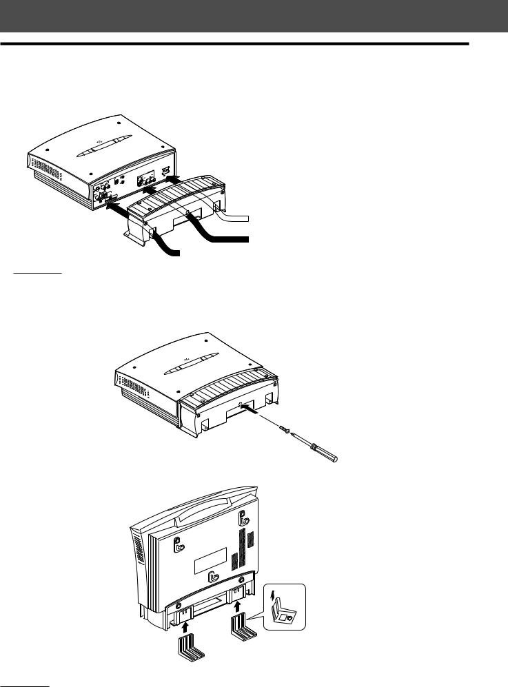
When placing the center unit vertically
When placing the center unit vertically, attach the supplied stand.
1 Connect the cords by passing them through the holes of the stand as illustrated below.
For connections, see pages 10 to 15.
OUT
VIDEO
|
|
|
|
|
DIGITAL |
IN |
|
|
|
|
|
OPTICAL |
AV |
|
|
AUX IN |
|
|
COMPU |
|
|
|
L |
|
|
LINK |
|
|
R |
|
|
|
|
|
-PWV70 |
|
|
|
|
|
|
TO SP |
|
|
|
|
|
|
|
AM LOOP |
|
|
|
|
|
FM 75 |
|
|
ANTENNA |
|
||
|
|
AM |
|
|
NTSC |
|
COAXIAL |
|
|
PAL |
OUT |
SELECT |
|
V |
VIDEO |
|
|
|||
H |
|
|
|
|
||
DISP.SET |
|
|
|
|
|
|
NOTE:
 Power cord
System cord, Video cord, Digital optical cord, RCA pin plug cord, and AV COMPULINK cord
FM and AM antennas
To avoid the interference from other cords, you had better separate three bundles of cords respectively.
2 Attach the stand to the center unit firmly using the supplied screw.
3 Attach the legs to the stand.
NOTE:
Avoid an unstable place when placing the center unit vertically. Make sure to place it on the level surface.
9
Connections
•Do not connect the AC power cord until all other connections have been made.
•Since different components often have different terminal names, carefully read the instructions supplied with the component you are going to connect.
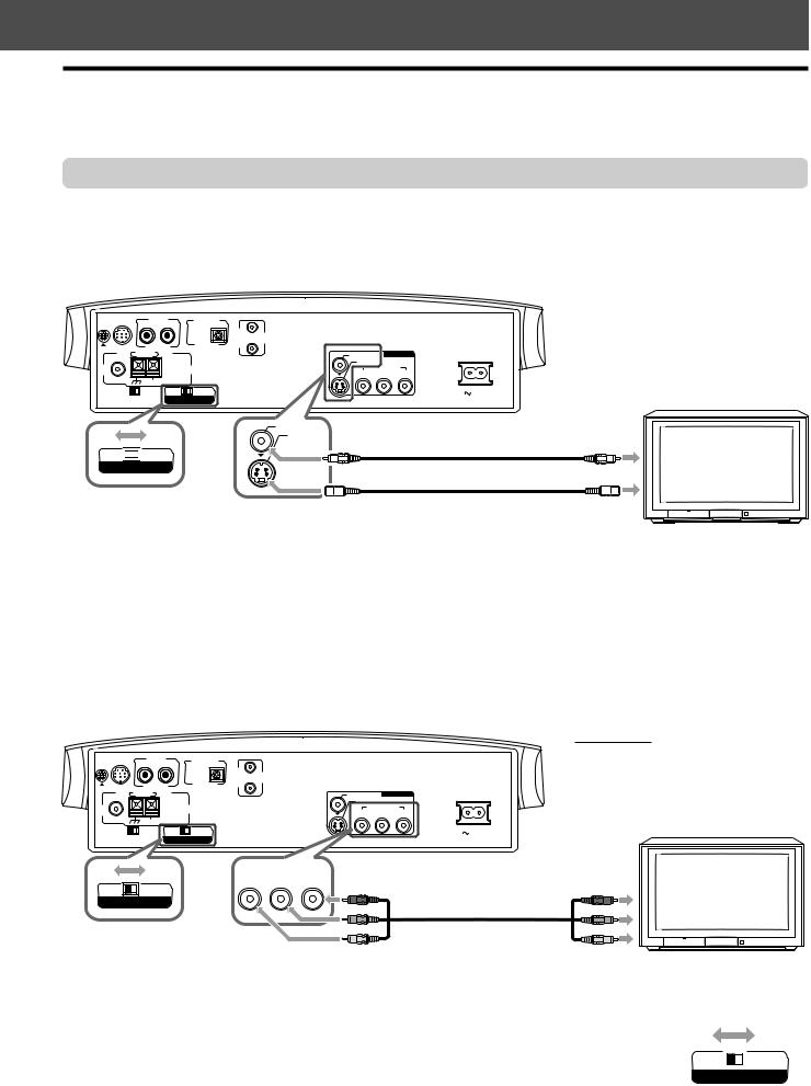
Connecting a TV
To view pictures and on-screen displays, connect a TV to the center unit.
•Connecting to a TV through a VCR, or to a TV with a built-in VCR, may cause distortion of picture.
•You need to set “MONITOR TYPE” in the PICTURE menu correctly according to the aspect ratio of your TV. See page 58.
7 To connect a TV without the component video input jacks
TO SP-PWV70 |
AUX IN |
|
|
DIGITAL IN |
|
|
|
|
|
|
|
|
|
AV |
|
|
|
|
|
|
|
|
COMPU |
|
|
|
|
R |
L |
|
OPTICAL |
LINK |
VIDEO OUT |
Center unit |
|
FM 75 |
AM LOOP |
|
|
|
VIDEO |
|||
|
|
|
|
S-VIDEO |
|
|
||
|
|
|
|
|
|
|
||
|
|
|
ANTENNA |
Y |
COMPONENT |
PR |
|
|
|
|
|
|
|
PB |
|
||
COAXIAL |
AM EXT |
|
|
|
|
|
|
|
|
|
|
|
|
|
|
|
|
H |
V |
|
PAL |
NTSC |
|
|
|
AC IN |
|
|
|
|
SELECT |
|
|
|
TV |
VIDEO
S-VIDEO
PAL 


 NTSC
NTSC
VIDEO OUT SELECT
Set the VIDEO OUT SELECT switch correctly. (See below.)
To composite video input
Video cord (supplied)
S-video cord (not supplied)
To S-video input
If your TV has S-video (Y/C-separation) jack, connect it using an S-video cord.
By using this jack, you can get a better picture quality than using composite video connection.
• Connect S-video cord by matching the ∞ mark on the plug to the one on the system.
7 To connect a TV with the component video input jacks
If your TV has the component video input jacks, connect it with the component video cord (not supplied) to view a high quality picture.
•Connect “Y” to “Y,” “PB” to “PB,” and “PR” to “PR” correctly.
•If your TV supports the progressive video input, you can enjoy a high quality picture by making the progressive scan mode active. See page 26.
TO SP-PWV70 |
AUX IN |
|
|
DIGITAL IN |
|
|
|
|
|
|
|
|
AV |
|
|
|
|
|
|
|
COMPU |
|
|
|
R |
L |
|
OPTICAL |
LINK |
|
|
FM 75 |
AM LOOP |
|
|
|
VIDEO |
VIDEO OUT |
|
|
|
|
|
S-VIDEO |
|
||
|
|
|
|
|
|
||
|
|
|
ANTENNA |
Y |
COMPONENT |
PR |
|
|
|
|
|
|
PB |
||
COAXIAL |
AM EXT |
|
|
|
|
|
|
|
|
|
|
|
|
|
|
H |
V |
|
PAL |
NTSC |
|
|
AC IN |
|
|
|
|
SELECT |
|
|
|
NOTE:
If the component video input jacks of your
TV are of the BNC type, use a plug adapter to convert the pin plugs to BNC plugs (not supplied).
TV
 COMPONENT
|
Y |
PB |
PR |
PAL |
NTSC |
|
|
VIDEO OUT SELECT
Set the VIDEO OUT SELECT switch correctly. (See below.)
Center unit
Red
Blue
Component video cord
(not supplied)
Green
To component video input
7 Selecting the color system
The center unit is compatible with the PAL and NTSC systems. Set the VIDEO OUT SELECT switch on |
|
|
|
the rear panel in standby mode to match the color system of your TV. Make sure that the color system |
|
|
|
of a DVD, Video CD, or SVCD disc labeled on the package matches your TV. |
|
|
|
• If you use a multi-system TV, by setting “MONITOR TYPE” in the PICTURE menu to an appropriate |
PAL |
|
NTSC |
“MULTI” option, the system outputs a video signal by the same format recorded on the disc (i.e. if |
VIDEO OUT SELECT |
||
you play an NTSC disc, the system outputs a signal by the NTSC format) regardless of the VIDEO |
|
|
|
OUT SELECT switch setting. See page 58. |
|
|
|
10
Getting Started
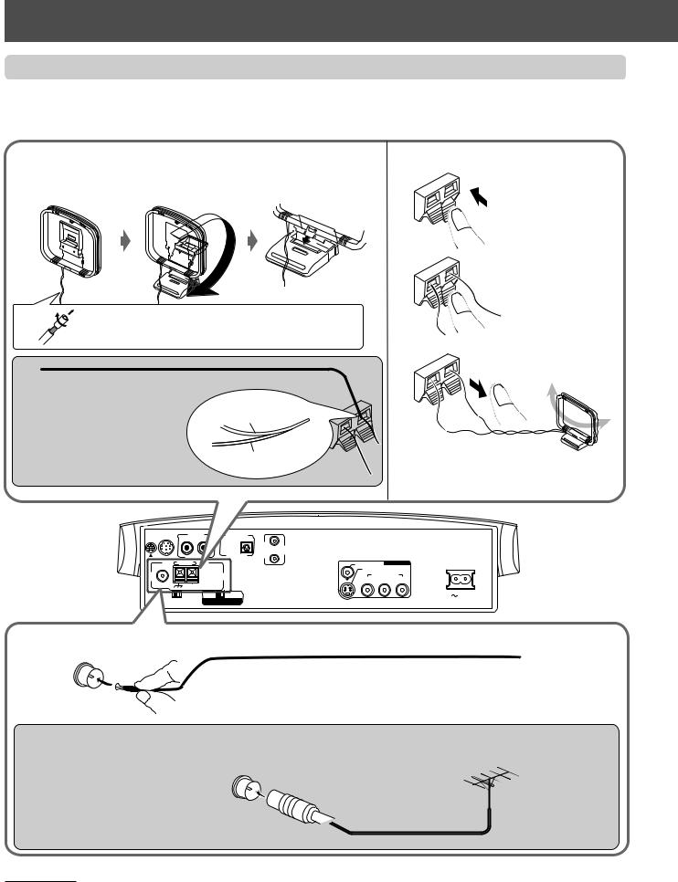
Connecting the FM and AM antennas
•Make sure the antenna conductors do not touch any other terminals, connecting cords, and power cords. This could cause poor reception.
7 AM loop antenna
Setting up AM loop antenna
Attach the AM loop to its base by snapping the tabs on the loop into the slot in the base.
If the antenna cord is covered with vinyl, remove the vinyl by twisting it as shown.
Outdoor single vinyl-covered wire (not supplied)
If reception is poor:
Connect an outdoor single vinylAM loop antenna covered wire to the AM EXT  terminal. (Keep the AM loop
antenna connected.)
Wire
Connecting AM loop antenna
1
Press and hold the terminal clamp.
2
Insert the antenna cord.
3 |
Release the finger from |
|
the clamp. |
•Turn the loop until you have the best reception.
Center unit
ANTENNA |
COMPONENT |
PR |
Y |
PB |
7 FM antenna
Connecting the supplied FM antenna
Extend the supplied FM antenna horizontally.
Outdoor FM antenna
(not supplied)
If reception is poor:
Connect an outdoor FM antenna with the standard type (coaxial)
connecter.
Outdoor FM antenna cord (not supplied)
NOTES:
•Disconnect the supplied FM Antenna before attaching a 75 Ω coaxial connector (the kind with a round wire going to an outdoor antenna).
•We recommend that you use a coaxial cable to the FM antenna, since it is well-shielded against interference.
11
Connecting the powered subwoofer
Connect the supplied powered subwoofer (SP-PWV70) using the supplied system cord.
• Connect the system cord by matching the 5 marks on the plugs to the ones on the system and powered subwoofer.
Powered subwoofer
TO SP-PWV70
System cord (supplied)
Ensure that the 5 mark on the plug faces down.
Center unit
TO SP-PWV70 |
AUX IN |
|
DIGITAL IN |
|
|
|
|
|
|
|
AV |
|
|
|
|
|
|
COMPU |
|
|
|
R |
L |
OPTICAL |
LINK |
|
|
FM 75 |
AM LOOP |
|
|
VIDEO |
VIDEO OUT |
|
|
|
|
S-VIDEO |
|
||
|
|
|
|
|
||
|
|
ANTENNA |
Y |
COMPONENT |
PR |
|
|
|
|
|
PB |
||
COAXIAL |
AM EXT |
|
|
|
|
|
|
|
|
|
|
|
|
H |
V |
PAL |
NTSC |
|
|
AC IN |
DISP.SET |
VIDEO OUT SELECT |
|
|
|
||
C O N N E C T O R
F R O M X V - T H V 7 0
VOLUME
MAX
MIN
PHASE
REVERSE
NORMAL
SUB WOOFER
C O N N E C T O R
F R O M X V - T H V 7 0
|
F R O N T S P E A K E R S |
|
|
CAUTION : |
|
S P E A K E R I M P E D A N C E |
4~16 |
|
|
|
LEFT |
|
|
RIGHT |
CENTER |
CAUTION : |
|
SPEAKER |
S P E A K E R I M P E D A N C E |
|
|
|
4~16 |
|
|
LEFT |
|
|
RIGHT |
CAUTION : |
4~16 |
|
S P E A K E R I M P E D A N C E |
||
REAR S P E A K E R S
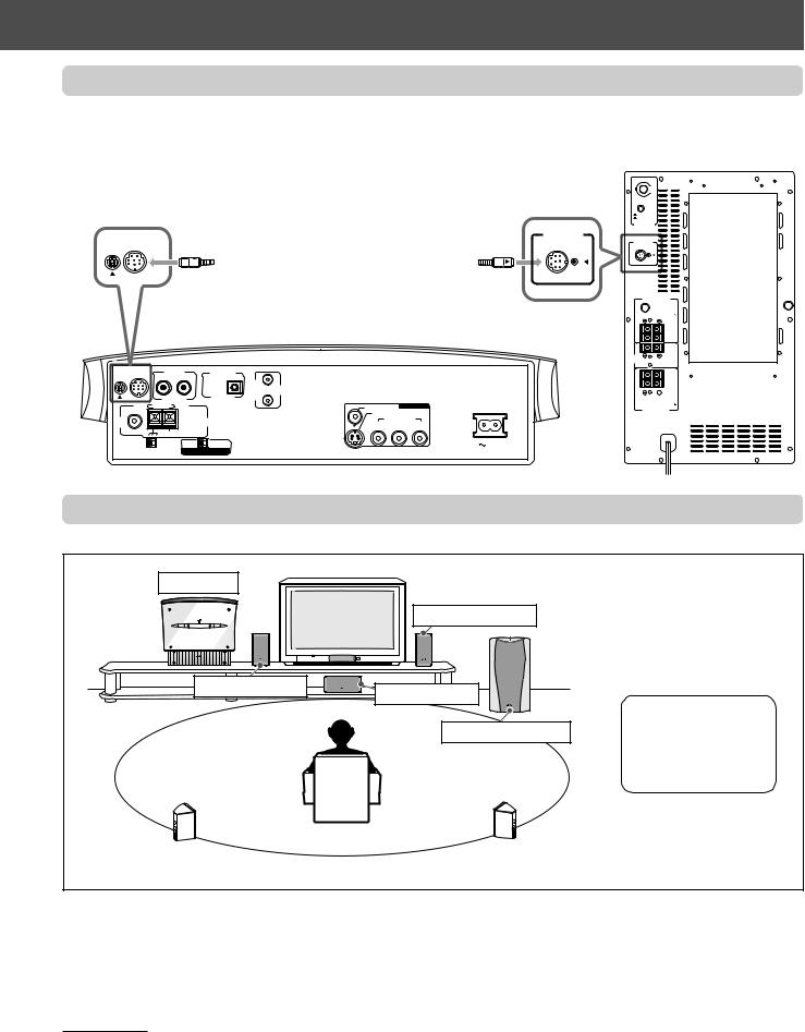
Connecting the satellite speakers
7 Speaker layout
Center unit
Left front speaker*
Right front speaker*
Center speaker*
Powered subwoofer*
*The speaker grilles are not removable. Trying to remove them by force may damage them.
Left rear speaker* |
|
Right rear speaker* |
|
|
|
When placing the speakers, to obtain the best possible sound from this system, you need to place all satellite speakers at the same distance from the listening position with the front of each speaker faced toward the listener.
When you cannot place them at the same distance from the listening position, you can make adjustment as if those speakers are placed at the best position. See page 61.
•Normally, place the powered subwoofer in front of you. (Since bass sound is non-directional, you do not need to place it at the same distance as the satellite speakers.)
NOTES:
•Although the satellite speakers and the powered subwoofer are magnetically shielded, the TV screen may be mottled. In this case, keep the distance from them to the TV by over 10 cm.
•For safety reasons, always ensure that there is a sufficient space behind the subwoofer.
•When you place the satellite speakers on the relatively high position, such as the top of your bookshelf, place them on a flat and level surface.
12

Getting Started
7 Connecting the satellite (front, center, rear) speakers
Connect the satellite speakers to the powered subwoofer using the supplied speaker cords.
• Connect the white cord to the red (+) terminal and the black cord to the black (–) terminal.
CAUTION:
•When you do not connect the supplied speakers but connect other (larger) speakers, use the speakers with the SPEAKER IMPEDANCE indicated by the speaker terminals on the rear panel of the subwoofer.
•DO NOT connect more than one speaker to one speaker terminal.
Before connecting the speaker cord
1 |
2 |
If the speaker cord is |
Fold the end of each |
covered with vinyl, |
speaker cord to avoid |
remove the vinyl by |
short-circuit. |
twisting it as shown |
|
above. |
|
Connecting the speaker cord to the satellite speakers
* The terminal of SP-XSV70 |
1 |
Press and hold the terminal clamp.
Front speakers* (SP-XSV70)
Center speaker (SP-XCV70)
Rear speakers* (SP-XSV70)
|
Groove |
Connect the |
Let the cables |
speaker cords. |
pass through the |
|
groove. |
2 |
3 |
Insert the speaker cord.
|
F R O N T S P E A K E R S |
|
|
CAUTION : |
|
|
N C E |
4~16 |
|
|
LEFT |
|
|
RIGHT |
CENTER |
CAUTION : |
|
SPEAKER |
S P E A K E R I M P E D A N C E |
|
|
|
4~16 |
|
|
LEFT |
|
|
RIGHT |
|
N C E |
4~16 |
|
A K E R S |
|
Release the finger from the terminal clamp.
Powered subwoofer
VOLUME
MAX
MIN
PHASE
REVERSE
NORMAL
SUB WOOFER
C O N N E C T O R
F R O M X V - T H V 7 0
|
F R O N T S P E A K E R S |
|
|
CAUTION : |
|
S P E A K E R I M P E D A N C E |
4~16 |
|
|
|
LEFT |
|
|
RIGHT |
CENTER |
CAUTION : |
|
SPEAKER |
S P E A K E R I M P E D A N C E |
|
|
|
4~16 |
|
|
LEFT |
|
|
RIGHT |
CAUTION : |
4~16 |
|
S P E A K E R I M P E D A N C E |
||
REAR S P E A K E R S
Connecting the speaker cord to the powered subwoofer
1 |
2 |
3 |
Open the terminal |
Insert the speaker |
Close the terminal |
clamp. |
cord. |
clamp. |
13
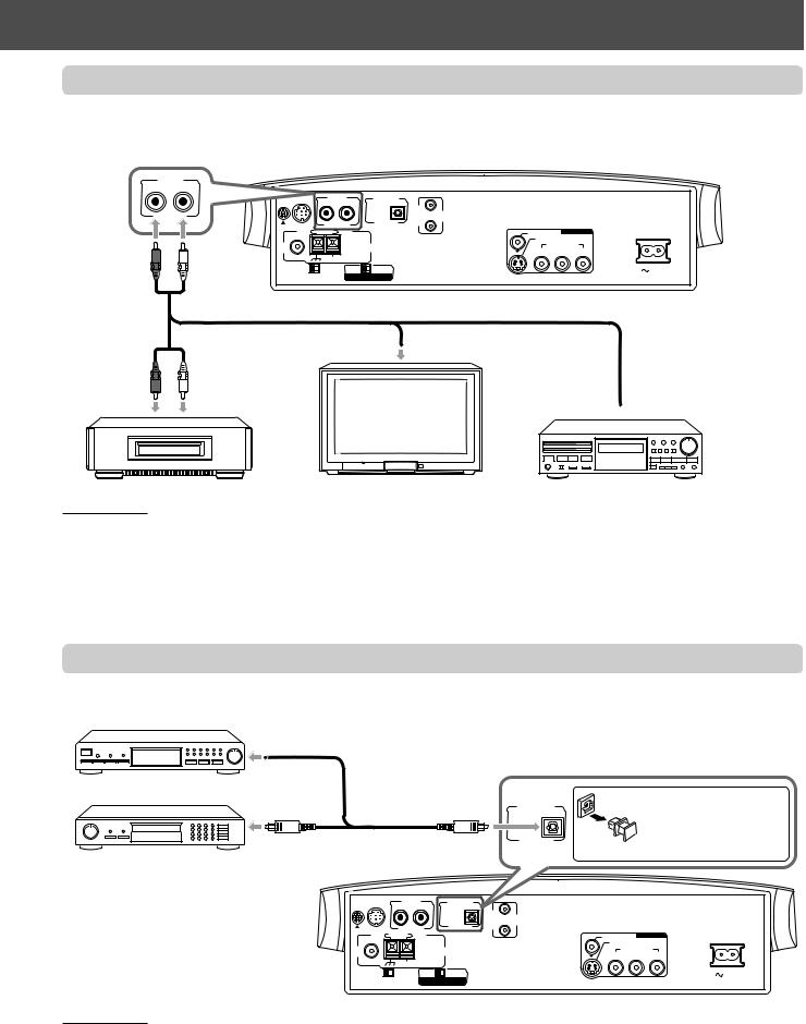
Connecting to an analog component
You can enjoy the sound of an analog component such as a VCR, TV, or Cassette recorder through this system. Connect an analog component using the cord with RCA pin plugs (not supplied).
• Connect the white plug to “AUX IN L” (the left audio jack), the red to “AUX IN R” (the right audio jack).
|
AUX IN |
|
|
|
|
|
|
AUX IN |
|
DIGITAL IN |
|
|
|
R |
L |
|
|
AV |
|
|
|
|
COMPU |
|
|
||
|
R |
L |
OPTICAL |
LINK |
|
|
|
LOOP |
|
|
VIDEO |
VIDEO OUT |
|
|
|
|
|
|||
|
|
|
|
S-VIDEO |
|
|
|
|
|
ANTENNA |
Y |
COMPONENT |
PR |
|
|
|
|
PB |
||
COAXIAL |
AM EXT |
|
|
H V |
PAL NTSC |
AC IN |
Center unit |
DISP.SET |
VIDEO OUT SELECT |
|
RCA pin plug cord
To audio output
To audio output
 To audio output
VCR |
TV |
Cassette recorder |
NOTES:
•If you connect a sound-enhancing device such as a graphic equalizer between the source components and this system, the sound output through this system may be distorted.
•When playing a video component such as a VCR:
–To listen to the sound, operate this system. (Select “AUX” as the source to play. See page 22.)
–To see the picture, connect the video output jack of the component to the video input jack of the TV, and select the correct input mode on the TV.
Connecting to a digital component
You can enjoy the sound of a digital component such as a DBS tuner or MD recorder through this system. Connect a digital component using the digital optical cord (not supplied).
DBS tuner
Digital optical cord
MD recorder
DIGITAL IN
OPTICAL
Before connecting a digital optical cord, unplug the protective plug.
|
TO SP-PWV70 |
AUX IN |
|
DIGITAL IN |
|
|
|
|
|
|
|
|
AV |
|
|
|
|
|
|
|
COMPU |
|
|
|
|
R |
L |
OPTICAL |
LINK |
|
|
|
FM 75 |
AM LOOP |
|
|
VIDEO |
VIDEO OUT |
|
|
|
|
|
S-VIDEO |
|
||
|
|
|
|
|
|
||
|
|
|
ANTENNA |
Y |
COMPONENT |
PR |
|
|
|
|
|
|
PB |
||
|
COAXIAL |
AM EXT |
|
|
|
|
|
|
|
|
|
|
|
|
|
Center unit |
H |
V |
PAL |
NTSC |
|
|
AC IN |
DISP.SET |
VIDEO OUT SELECT |
|
|
|
|||
NOTES:
When playing a video component such as a DBS tuner:
•To listen to the sound, operate this system. (Select “AUX DIGITAL” as the source to play. See page 22.)
•To see the picture, connect the video output jack of the component to the video input jack of the TV directly, and select the correct input mode on the TV.
14
Getting started
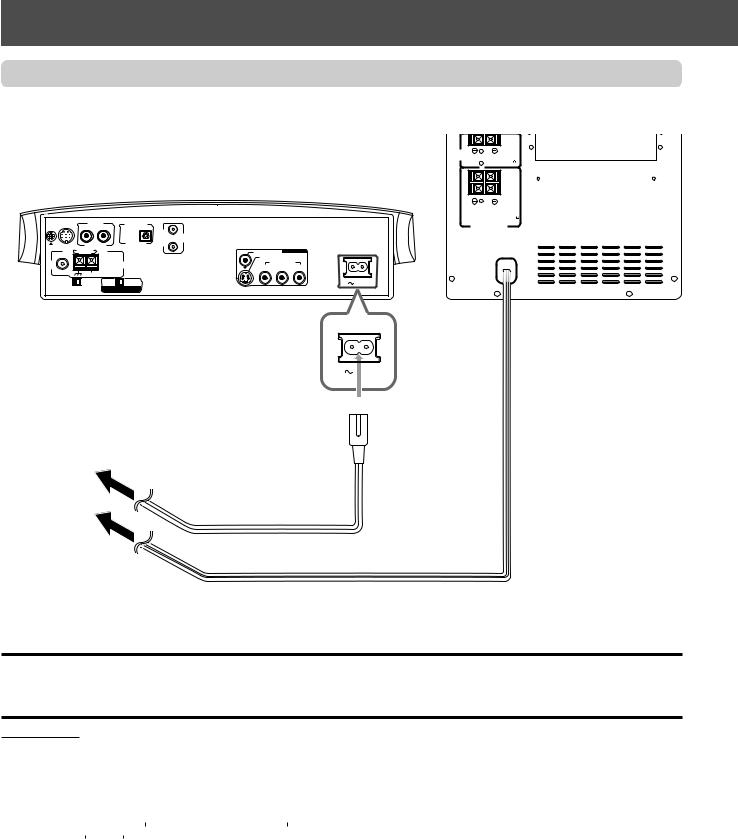
Connecting the power cord
Make sure that all connections have been made, before plugging the power cords of the center unit and powered subwoofer.
CENTER |
CAUTION : |
SPEAKER |
S P E A K E R I M P E D A N C E |
|
4~16 |
LEFT |
RIGHT |
CAUTION :
S P E A K E R I M P E D A N C E 4~16
TO SP-PWV70 |
AUX IN |
|
DIGITAL IN |
|
|
REAR S P E A K E R S |
|
|
|
|
AV |
|
|
|
|
|
|
COMPU |
|
|
|
R |
L |
OPTICAL |
LINK |
|
|
FM 75 |
AM LOOP |
|
|
VIDEO |
VIDEO OUT |
|
|
|
|
S-VIDEO |
|
||
|
|
|
|
|
||
|
|
ANTENNA |
Y |
COMPONENT |
PR |
|
COAXIAL |
|
|
|
PB |
||
AM EXT |
|
|
|
|
|
|
|
|
|
|
|
|
|
H |
V |
PAL |
NTSC |
|
|
|
DISP.SET |
VIDEO OUT SELECT |
|
|
|
||
Center unit |
Powered subwoofer |
1 Firmly insert the |
|
supplied power cord into |
|
the Ó AC IN socket on |
AC IN |
the rear panel of the |
|
center unit. |
|
2Plug the power cords into AC outlets.
Plug into AC outlets.
Power cord (supplied)
Power cord
CAUTIONS:
•Disconnect the power cord before cleaning or moving the system.
•Do not touch the power cord with wet hands.
•Do not pull on the power cord to unplug the cord.
When unplugging the cord, always grasp the plug so as not to damage the cord.
NOTES:
• Keep the power cords away from the connecting cords. The power cords may cause noise or screen interference.
•The preset settings such as preset stations, and sound adjustment may be erased in a few days in the following cases:
–When you unplug the power cord of the center unit.
–When a power failure occurs.
•The speakers will not produce any sound if the power cord of the powered subwoofer is removed from the AC outlet while the center unit is
turned on.
In this case, press AUDIO  on the remote control or
  on the center unit to turn off the power, plug in the powered subwoofer, then press AUDIO
  or
or  again.
15
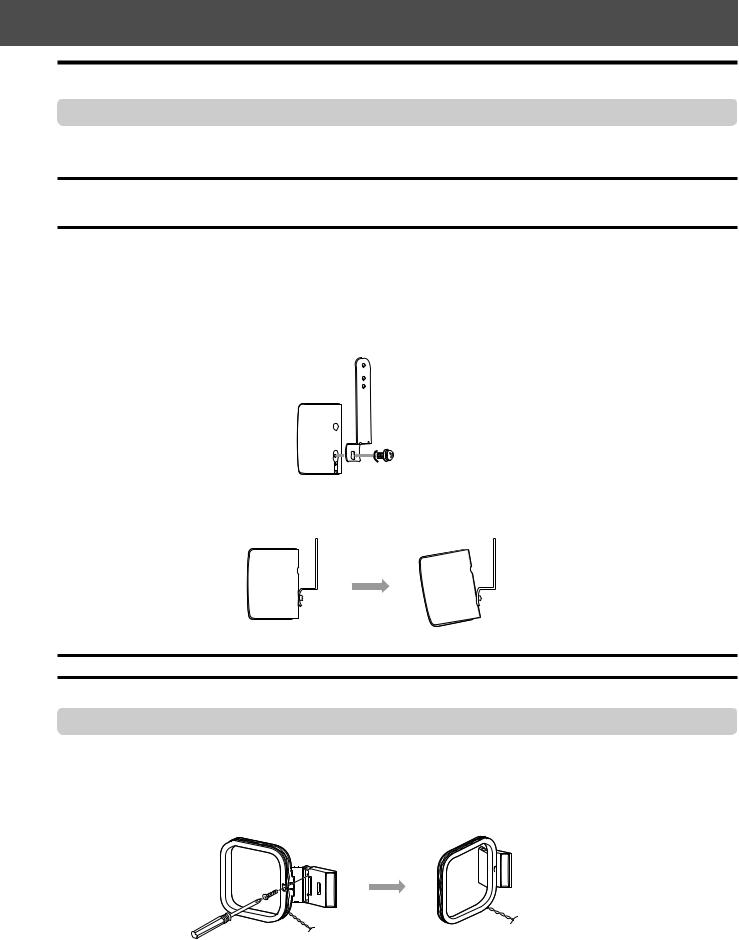
Installing the equipment on the wall
When attaching the rear speakers to a wall
Using the supplied speaker wall brackets, you can fix the rear speakers to the wall.
CAUTION: Attaching the brackets to the wall
When attaching the brackets to the wall, have them attached to the wall by a qualified person.
DO NOT attach the brackets to the wall by yourself to avoid an unexpected damage due to their falling from the wall, caused by incorrect attachment or weakness in the wall.
Location of attachment to wall:
Take care when selecting a location for attaching rear speakers to the wall. Injury to personnel, or damage to equipment, may result if the speakers are attached in a location which interferes with daily activities.
Attaching speakers to the brackets
1 Use the supplied screws to attach the brackets to the rear speakers.
2 Adjust the angle of the rear speakers.
Loosen the screw slightly, make an adjustment, and then tighten the screw firmly.
CAUTION:
If the screws are not tightened firmly, this may cause injury to personnel or damage to equipment.
When attaching the AM loop antenna to a wall
You can attach the AM loop antenna to the wall.
Mount the AM loop antenna to a wall using the screw (not supplied) as illustrated below.
16
Getting started
When attaching the center unit to a wall
You can attach the center unit to a wall.
CAUTIONS: location of attachment to a wall
•Take care when selecting a location for attaching the center unit to the wall. Injury to personnel, or damage to the center unit, may result if the center unit is attached in a location which interferes with daily activities, or a location that the users are liable to knock their bodies or heads against the center unit.
•Avoid a location above a bed, sofa, water tank, sink, etc. or in a passage.
CAUTIONS: attachment to a wall
•The center unit weighs approximately 2.93 kg. When you operate the buttons on the center unit, an additional force will be applied to the center unit in downward direction. Therefore, sufficient care must be required when attaching the center unit to a wall to prevent any accidents caused by the unit’s falling off.
•Before attaching the center unit to a wall, check the wall (or other related aspects) you want to attach it to, and verify whether the strength of the wall will be sufficient not only to support the weight of the center unit itself but also to withstand the additional downward force which will be applied to it during operations.
(Do not attach the center unit to a plywood or plasterboard wall. The center unit will fall and sustain damage as a result.) If you cannot judge the strength of the wall or other aspects, consult a qualified person (such as a qualified constructor).
•The screws needed for attachment are not supplied. Use screws which are compatible with the strength and material of the pillar or wall.
•When attaching the center unit, the screws must be secured tightly in all three locations. Failure in attaching the center unit to the wall using all three holes on the back of the center unit makes for an unstable attachment, and it constitutes a safety hazard as the center unit may fall down.
Example of attachment
The procedure below is an example of how to attach the center unit to a wall:
It does not make any guarantee for safety while using the center unit on the wall. Take into account such factors as the material, strength, and the status of the wall as well as the reinforcing material, and the possible changes that will take place over time.
NOTES:
•You need to connect the cords to the center unit (and attach the supplied stand) before attaching it to the wall.
•DO NOT plug the power cord into an AC outlet before attaching the center unit to the wall.
•When attaching the supplied stand to the center unit, connect the video cords, system cord, and so on by passing them through the holes at the bottom of the stand, and do not attach the legs to the stand. See page 9.
1Select the place where the center unit is to be attached.
2Mount three screws (not supplied) to the wall.
Use the screws as illustrated below.
You can use the supplied paper pattern to mark the positions where the screws are mounted.
Keep the space of 6 to 7 mm.
|
Wall |
6 to 9 mm |
3 mm |
Within 3 mm
20 to 30 mm
Screws (not supplied)
17

3 Hook the center unit onto the mounted screws, and slide it to left, then down.
Make sure that the center unit is attached securely.
• Adjust the screws if the center unit is not attached securely.
Slide to left, then down.
NOTES:
•Do not place anything on top of the center unit. Doing so may cause the center unit to fall down, and cause injury to the persons arround.
•Do not climb onto the center unit or hang from it. Doing so may damage the center unit and/or cause injury to the person.
Take care specially when there are small children at the home.
• Avoid sandwiching the cords between the unit and wall. This may upset the balance of the center unit, and cause the center unit to fall down.
•Make sure that the connected cords will not interfere with daily activities and that the users will not be caught in the cords.
•Do not pull the connected cords with excessive force.
•Check regularly that none of the screws are loose.
•In the event that the center unit has fallen, turn the power off, disconnect the power plug from the AC outlet, and contact your dealer for an inspection and repairs. Using it in this state may cause a fire or electrical shock.
•Do not place valuables (breakables) underneath the location where the center unit is attached. They will be damaged if the center unit should fall.
•The manufacturer accepts absolutely no liability for any accidents or damage resulting from inadequate assembly or mounting, insufficient strength of attachment, misuse or abuse, or natural disasters.
18
Getting Started
Using the remote control
The remote control makes it easy to use many of the functions of the system at a distance of up to 7 m (23 feet) away.
•You can also operate other components from the remote control supplied with this system.
–To operate your TV, see page 20.
–To operate your VCR, CATV convertor, or DBS tuner, see page 69.
Putting batteries in the remote control
Before using the remote control, put two supplied batteries first.
1On the back of the remote control, remove the battery cover.
2Insert batteries.
• Make sure to match the polarity: (+) to (+) and (–) to (–).
3Replace the cover.
1 |
2 |
3 |
If the range or effectiveness of the remote control decreases, replace the batteries. Use two R6P (SUM-3)/AA (15F) type drycell batteries.
CAUTION:
Follow these precautions to avoid leaking or cracking batteries:
•Place batteries in the remote control so they match the polarity: (+) to (+) and (–) to (–).
•Use the correct type of batteries. Batteries that look similar may differ in voltage.
•Always replace both batteries at the same time.
•Do not expose batteries to heat or flame.
Operating the system from the remote control
Aim the remote control directly at the remote sensor on the center unit.
•To control other components, aim the remote control directly at the remote sensor on each component. Refer also to their instruction manuals .
•To operate the remote control properly, do not hide the remote sensor by placing any obstruction.
SOURCE |
VOL |
D V D D I G I T A L C I N E M A S Y S T E M |
Remote sensor |
T H - V 7 0 |
|
When the center unit is placed vertically
SOURCE |
VOL |
When the center unit is placed horizontally
NOTE:
When the moving panel is open, the remote sensor looks up, so the remote control may not work.
You can use the remote control while the moving panel is shut.
19
Using the remote control for TV operations
You can operate your TV using the remote control supplied with this system.
• Refer also to the instruction manuals supplied with your TV.
|
|
TV |
AUDIO |
AUX |
FM/AM |
|
VCR |
AUDIO |
ANGLE |
SUBTITLE |
DECODE |
RETURN |
DIGEST |
ZOOM |
VFP |
|
7 Setting the remote control signal for operating your TV. |
TV |
• You can operate your TV without setting the remote control signal if your TV is a |
button |
JVC TV. |
|
1 Slide the remote control mode selector to ”AUDIO/TV/VCR.” |
|
+ |
|
TOP MENU MENU |
ZOOM |
PROGRESSIVE |
|
||
|
– |
SOUND |
CONTROL |
– SUBWOOFER + |
EFFECT |
|
||
VCR |
1 |
|
2 |
3 |
|
|
– |
CENTER |
+ |
TEST |
|
|
4 |
|
5 |
6 |
Number |
SLEEP |
– |
REAR-L |
+ |
|
|
|
7 |
|
8 |
9 |
buttons |
SETTING |
– |
REAR-R |
+ |
|
|
|
|
||||
|
10 |
|
0 |
+10 |
TV CONTROL |
|
TV RETURN FM MODE |
100+ |
|||
SCREEN |
|
|
|
AUDIO/ |
button |
ON |
|
|
|
|
|
|
|
|
|
TV/VCR |
Remote |
|
|
|
|
CATV/DBS |
|
|
|
ENTER |
|
SURROUND |
control mode |
CHOICE |
|
|
|
||
|
|
|
MODE |
||
|
|
|
|
|
selector |
TV VOL |
CHANNEL |
VOLUME |
CHANNEL |
||
|
|
|
|
|
+/– buttons |
|
TV/VIDEO MUTING |
|
TV/VIDEO |
||
1 |
|
|
|
¡ |
|
/REW |
PLAY |
|
FF/ |
button |
|
|
|
||||
DOWN |
|
TUNING |
|
UP |
TV VOL +/– |
REC |
|
STOP |
|
PAUSE |
|
MEMORY |
|
|
|
STROBE |
buttons |
|
DIMMER |
|
|
||
RM–STHV70U
DVD CINEMA SYSTEM
2Press and hold TV  .
.
• Keep it pressed until step 4 is finished.
3Press TV CONTROL.
4Press Number buttons (1-9, 0) to enter a manufacturer’s code (2 digit).
See the list below to find the codes.
•For a Hitachi TV, press 1, then 0.
•For a Toshiba TV, press 0, then 8.
5Release TV  .
.
6Try to operate your TV by pressing TV  .
.
When your TV turns on or off, you have entered the correct code.
If there are more than one code listed for your brand of TV, try each one until you enter the correct one.
Manufacturers’ codes* for TV
Manufacturer |
Code |
Manufacturer |
Code |
JVC |
01 |
Samsung |
12 |
|
|
|
|
Hitachi |
10 |
Sanyo |
13 |
|
|
|
|
Magnavox |
02 |
Sharp |
06 |
|
|
|
|
Mitsubishi |
03 |
Sony |
07 |
|
|
|
|
Panasonic |
04,11 |
Toshiba |
08 |
|
|
|
|
RCA |
05 |
Zenith |
09 |
|
|
|
|
*Manufacturers’ codes are subject to change without notice. If they are changed, this remote control cannot operate the equipment.
7To operate your TV
You can use the following buttons for operating your TV:
IMPORTANT:
When using the remote control, check to see if its |
AUDIO/ |
|
remote control mode selector is set to the correct |
TV/VCR |
|
CATV/DBS |
|
|
position: |
|
|
|
|
To operate TV, set it to “AUDIO/TV/VCR.”
TV  : Turns on and off your TV. TV VOL +/–: Adjust the volume.
TV/VIDEO: Select the input mode (either TV or VIDEO).
•After pressing TV CONTROL, you can perform the following operations on the TV.
CHANNEL +/–: Changes the channels. 1-10, 0, +10 (100+): Selects the channel.
20
Basic operations
This section mainly explains operations commonly used when you enjoy this system.
•This manual mainly explains operations when the center unit is placed vertically (the DISP.SET selector is set to “V”) as an example.
•Turn also on your TV and select the correct input mode on the TV.
IMPORTANT:
When using the remote control, check to see if its |
AUDIO/ |
|
TV/VCR |
|
|
remote control mode selector is set to the correct |
CATV/DBS |
|
position: |
|
|
|
|
|
|
|
To operate this system, set it to “AUDIO/TV/VCR.”
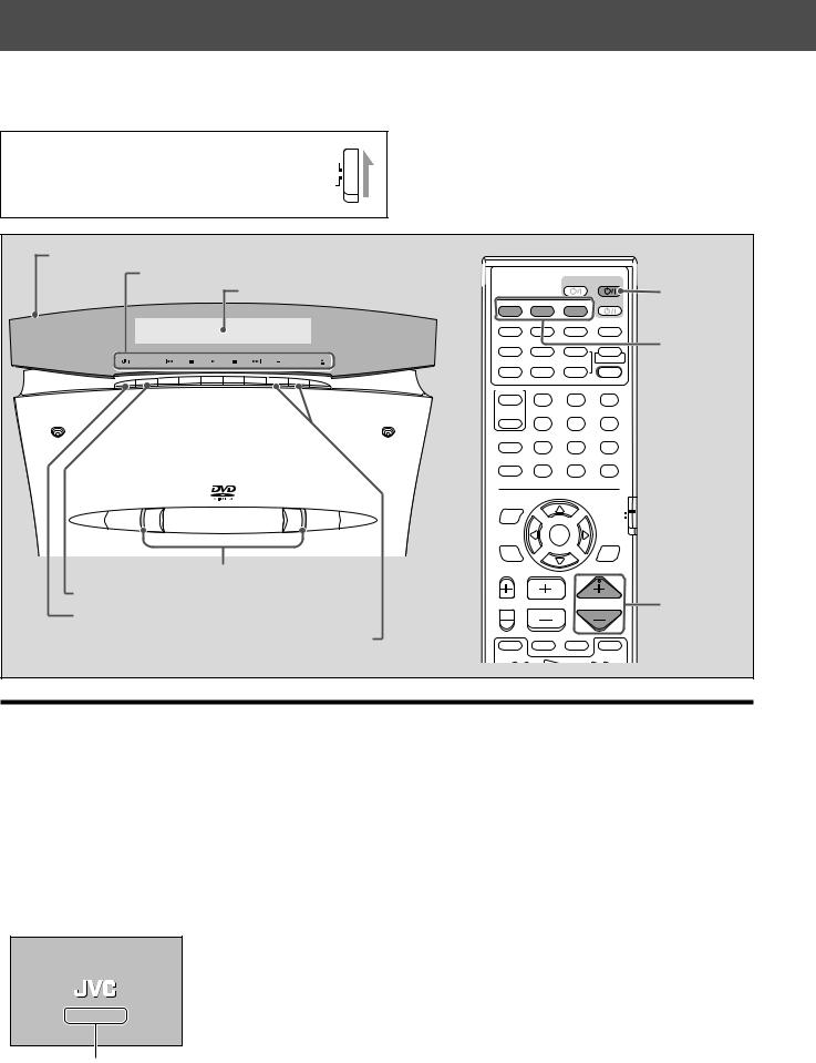
Moving panel
Button name indicators
Display window |
TV |
AUDIO |
|
|
|
AUX |
FM/AM |
VCR |
AUDIO |
ANGLE SUBTITLE |
DECODE |
AUDIO  button
|
|
RETURN |
DIGEST |
ZOOM |
VFP |
Source |
||
|
|
|
|
|
|
+ |
|
selecting |
SOURCE |
VOL |
TOP MENU |
MENU |
ZOOM |
PROGRESSIVE |
|||
|
|
|
buttons |
|||||
|
|
|
|
|
|
– |
SOUND |
|
|
|
CONTROL |
– SUBWOOFER + |
EFFECT |
|
|||
|
|
VCR |
1 |
|
|
2 |
3 |
|
|
|
|
– |
CENTER |
+ |
TEST |
|
|
|
|
TV |
4 |
|
|
5 |
6 |
|
|
|
SLEEP |
– |
REAR-L |
+ |
|
|
|
|
|
|
7 |
|
|
8 |
9 |
|
|
|
SETTING |
– |
REAR-R |
+ |
|
|
|
|
|
|
10 |
|
|
0 |
+10 |
|
|
|
TV RETURN |
FM MODE |
100+ |
|
|||
|
|
ON |
|
|
|
|
|
|
|
|
SCREEN |
|
|
|
|
AUDIO/ |
|
|
|
|
|
|
|
|
TV/VCR |
|
|
D V D D I G I T A L C I N E M A S Y S T E M |
|
|
|
|
|
|
|
|
T H - V 7 0 |
|
|
|
|
|
CATV/DBS |
|
|
|
|
|
|
|
|
|
|
|
|
|
|
ENTER |
|
SURROUND |
|
|
|
|
CHOICE |
|
|
|
|
MODE |
|
Illumination lamps
SOURCE button
 button
VOL +/– buttons
TV VOL CHANNEL |
VOLUME |
TV/VIDEO MUTING
1¡
VOLUME +/– buttons
Turning on/off the system
From the remote control: On the center unit:
Press AUDIO  to turn the power on. Press
  to turn the power on.
•When you place the center unit vertically:
The moving panel stands up.
The illumination lamps and the button name indicators light up, and the current source name appears on the display window.
•When you place the center unit horizontally:
The illumination lamps and the button name indicators light up, and the current source name appears on the display window.
•When DVD, AUX, or AUX DIGITAL is selected as the source (see page 22), the opening screen* appears on the TV screen.
* Opening screen
NOW READING
Message area
The following messages may appear in the message area depending on the status of this system.
• “LOADING”/“EJECT”: |
Appears when inserting or removing a disc. |
• “NOW READING”: |
Appears when the system is reading the disc information. |
• “REGION CODE ERROR!”: Appears when the region code of the DVD does not match
|
the system. |
|
The DVD cannot be played back. |
• “NO DISC”: |
Appears when no disc is inserted. |
21
Loading...