


 Loading...
SERVICE MANUAL
Mini DV/S-VHS VIDEO CASSETTE RECORDER
SR-VS30E/EK
TV
CABLE/SAT DV VHS
1 LCD PROG AUDIO |
– –:– – TV/VCR |
2
1 |
2 |
|
3 |
|
4 |
5 |
|
6 |
3 |
VPS/PDC |
DAILY/QTDN. WEEKLY/HEBDO |
|||
7 |
8 |
|
9 |
4 |
|
|
|
|
4 |
0000 |
AUX |
|
|
MENU |
|
0 |
|
|
|
|
|
|
|
ENTER/ENTREE |
1 PROG |
|
30 SEC |
OK 3 |
|
2 |
|
|
|
|
START |
STOP |
DATE |
PR |
|
DEBUT |
FIN |
|
|
|
|
EXPRESS |
|
|
|
|
TV PR |
+ |
|
|
T |
|
|
|
+ |
V |
|
|
|
|
– |
|
|
|
TV |
|
TV PR |
– |
|
|
PULL-OPEN |
|
|
|
|
|
TIRER-OUVRIR |
|
|
PR / + |
|
|
|
|
|
PUSH / TURN |
|
|
|
|
DV |
VHS |
24H |
|
DV |
DUB |
VHS |
EXPRESS |
|
|
|
COPIE |
|
|
|
|
|
|
|
1 |
3 |
2 |
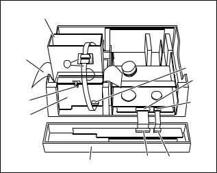
PULL-OPEN TIRER-OUVRIR
625
SPECIFICATIONS (The specifications shown pertain specifically to the model SR-VS30E.)
GENERAL
Power requirement : AC 220 V - 240 Vd, 50 Hz/60 Hz Power consumption
Power on |
: 31 W |
Power off |
: 6.5 W |
Temperature |
: 5°C to 40°C |
Operating |
|
Storage |
: –20°C to 60°C |
Operating position |
: Horizontal only |
Dimensions (WxHxD) |
|
|
: 435 mm x 106 mm x 380 mm |
Weight |
: 5.1 kg |
Input/Output |
: 21-pin SCART connectors: |
IN/OUT x 1, IN/DECODER x 1 RCA connectors:
VIDEO IN x 1, AUDIO IN x 1, AUDIO OUT x 1
S-Video connectors: IN x 1, OUT x 1 DV connector:
IN/OUT x 1 (4-pin, IEEE1394 conformity, digital input/output)
VHS DECK VIDEO/AUDIO
DV DECK VIDEO/AUDIO
Signal system |
: PAL-type colour signal, 625 lines |
|
50 fields |
Recording system |
: Digital Component Recording |
Format |
: DV format (SD mode) |
Cassette |
: Mini DV Cassette |
Maximum recording time |
|
(SP) |
: 80 min. with M-DV80ME cassette |
(LP) |
: 120 min. with M-DV80ME cassette |
Audio recording system
:PCM 48 kHz, 16 bit (2 ch)/ 32 kHz, 12 bit (4 ch)
TUNER/TIMER
TV channel storage capacity
: 99 positions (+AUX position) Tuning system : Frequency synthesized tuner Channel coverage : VHF 47 MHz – 89 MHz/
104 MHz – 300 MHz/
302 MHz – 470 MHz UHF 470 MHz – 862 MHz
Memory backup time
: Approx. 10 min.
Signal system |
: PAL-type colour signal and CCIR |
|
monochrome signal, 625 lines |
|
50 fields |
Recording system |
: DA4 (Double Azimuth) head helical |
|
scan system |
Format |
: S-VHS/VHS PAL standard |
Signal-to-noise ratio: 45 dB
Horizontal resolution
(SP/LP) |
: 250 lines (VHS) |
|
|
|
400 lines (S-VHS) |
||
Frequency range |
: 70 |
Hz to 10,000 |
Hz (Normal audio) |
|
20 |
Hz to 20,000 |
Hz (Hi-Fi audio) |
Maximum recording time |
|
||
(SP) |
: 240 min. with E-240 video cassette |
||
(LP) |
: 480 min. with E-240 video cassette |
||
ACCESSORIES
Provided accessories
:RF cable,
21-pin SCART/RCA cable, BNC/RCA adapter x 2, Satellite Controller,
Infrared remote control unit, "R6" battery x 2
Specifications shown are for SP mode unless otherwise specified. E.& O.E. Design and specifications subject to change without notice.
SR-VS30E/EK V14SD1
This service manual is printed on 100% recycled paper. COPYRIGHT © 2002 VICTOR COMPANY OF JAPAN, LTD
No.82910
March 2002

TABLE OF CONTENTS
Section Title Page
Important Safety Precautions
INSTRUCTIONS
1. DISASSEMBLY |
1-1 |
1.1 HOW TO REMOVE THE MAJOR PARTS ........................................ |
|
1.1.1 Introduction .................................................................................. |
1-1 |
1.2 HOW TO READ THE DISASSEMBLY AND ASSEMBLY .................. |
1-1 |
1.3 DISCONNECTION OF CONNECTORS (WIRES) ............................ |
1-1 |
1.4 HOW TO REMOVE THE MAJOR PARTS <COM section> .............. |
1-2 |
1.4.1 Disassembly flow chart ................................................................ |
1-2 |
1.4.2 Disassembly/assembly method <COM section> ......................... |
1-2 |
1.5 HOW TO REMOVE THE MAJOR PARTS <VHS section> ............... |
1-4 |
1.5.1 Disassembly flow chart ................................................................ |
1-4 |
1.5.2 DIsassembly/assembly method <VHS section> .......................... |
1-4 |
1.6 HOW TO REMOVE THE MAJOR PARTS <DV section> .................. |
1-6 |
1.6.1 Disassembly flow chart ................................................................ |
1-6 |
1.6.2 Disassembly/assembly method <DV section> ............................. |
1-6 |
1.7 CONNECTION .................................................................................. |
1-8 |
1.8 SERVICE POSITIONS .................................................................... |
1-10 |
1.8.1 Requirement PATCH CORDS .................................................... |
1-10 |
1.8.2 Service position <VHS SIDE> .................................................... |
1-10 |
1.8.3 Service position <DV FOIL SIDE> ............................................. |
1-10 |
1.8.4 Service position <DV COMPONENT SIDE> .............................. |
1-11 |
1.9 Jig RCU mode ................................................................................. |
1-11 |
1.9.1 Setting the Jig RCU mode ......................................................... |
1-11 |
1.9.2 Setting the User RCU mode ...................................................... |
1-11 |
1.10 MECHANISM SERVICE MODE ................................................... |
1-12 |
1.10.1 How to set the “MECHANISM SERVICE MODE” .................... |
1-12 |
1.11 EMERGENCY DISPLAY FUNCTION ............................................ |
1-13 |
1.11.1 Displaying the emergency information ..................................... |
1-13 |
1.11.2 Clearing the emergency history ............................................... |
1-13 |
1.11.3 Emergency content description ................................................ |
1-14 |
1.11.4 Emergency detail information <1> ........................................... |
1-15 |
1.11.5 Emergency detail information <2> ........................................... |
1-16 |
2. MECHANISM ADJUSTMENT (VHS) |
2-1 |
2.1 BEFORE STARTING REPAIR AND ADJUSTMENT ......................... |
|
2.1.1 Precautions .................................................................................. |
2-1 |
2.1.2 Checking for Proper Mechanical Operations ............................... |
2-1 |
2.1.3 Manually Removing the Cassette Tape ....................................... |
2-1 |
2.1.4 Jigs and Tools Required for Adjustment ....................................... |
2-2 |
2.1.5 Maintenance and Inspection ........................................................ |
2-3 |
2.2 REPLACEMENT OF MAJOR PARTS ............................................... |
2-6 |
2.2.1 Before Starting Disassembling |
2-6 |
(Phase matching between mechanical parts) ............................... |
|
2.2.2 How to Set the Mechanism Assembling Mode ............................. |
2-6 |
2.2.3 Cassette Holder Assembly ........................................................... |
2-6 |
2.2.4 Pinch Roller Arm Assembly .......................................................... |
2-8 |
2.2.5 Guide Arm Assembly and Press Lever Assembly ........................ |
2-8 |
2.2.6 Audio Control Head ...................................................................... |
2-8 |
2.2.7 Loading Motor .............................................................................. |
2-8 |
2.2.8 Capstan Motor ............................................................................. |
2-9 |
2.2.9 Pole Base Assembly (supply or take-up side) .............................. |
2-9 |
2.2.10 Rotary Encoder ........................................................................ |
2-10 |
2.2.11 Clutch Unit ................................................................................ |
2-10 |
2.2.12 Change Lever Assembly, Direct Gear, Clutch Gear |
2-10 |
and Coupling Gear .................................................................... |
|
2.2.13 Link Lever ................................................................................ |
2-11 |
2.2.14 Cassette Gear, Control Cam and Worm Gear ......................... |
2-11 |
2.2.15 Control Plate ............................................................................ |
2-11 |
2.2.16 Loading Arm Gear (supply or take-up side) |
2-12 |
and Loading Arm Gear Shaft .................................................... |
|
2.2.17 Take-up Lever, Take-up Head and Control Plate Guide .................. |
2-13 |
2.2.18 Capstan Brake Assembly ......................................................... |
2-13 |
2.2.19 Sub Brake Assembly (take-up side) ......................................... |
2-13 |
2.2.20 Main Brake Assembly (take-up side), |
|
Reel Disk (take-up side) |
2-13 |
and Main Brake Assembly (supply side) ................................... |
|
2.2.21 Tension Brake Assembly, Reel Disk (supply side) |
2-14 |
and Tension Arm Assembly ....................................................... |
|
2.2.22 Idler Lever, Idler Arm Assembly ............................................... |
2-14 |
2.2.23 Stator Assembly ....................................................................... |
2-14 |
2.2.24 Rotor Assembly ........................................................................ |
2-14 |
2.2.25 Upper Drum Assembly ............................................................. |
2-15 |
2.3 COMPATIBILITY ADJUSTMENT .................................................. |
2-16 |
2.3.1 Checking/Adjustment of FM Waveform Linearity ....................... |
2-16 |
2.3.2 Checking/Adjustment of the Height and Tilt of the Audio Control Head .................... |
2-17 |
2.3.3 Checking/Adjustment of the Audio Control Head Phase (X-Value) ............... |
2-17 |
2.3.4 Checking/Adjustment of the Standard Tracking Preset ............. |
2-18 |
2.3.5 Checking/Adjustment of the Tension Pole Position .................... |
2-18 |
MECHANISM ADJUSTMENT (DV) |
2-20 |
2.4 PREPARATION ............................................................................... |
|
2.4.1 Precautions ................................................................................ |
2-20 |
2.4.2 Tools Required for Adjustments ................................................. |
2-20 |
2.4.3 Disassembly and Assembly Procedures .................................... |
2-20 |
2.4.4 Screws and Washers Used in Disassembly/ |
2-20 |
Assembly of the Mechanism Assembly ...................................... |
|
2.5 DISASSEMBLY/ASSEMBLY OF THE MECHANISM ASSEMBLY ................... |
2-21 |
2.5.1 Introduction ................................................................................ |
2-21 |
2.5.2 Mechanism Modes ..................................................................... |
2-21 |
2.6 MECHANISM TIMING CHART ....................................................... |
2-23 |
2.7 MECHANISM ASSEMBLY/DISASSEMBLY PROCEDURE TABLE .................. |
2-24 |
2.8 DISASSEMBLY/ASSEMBLY ........................................................... |
2-26 |
2.9 LIST OF PROCEDURES FOR DISASSEMBLY ............................. |
2-34 |
2.10 MECHANISM PHASE CHECK/ADJUSTMENT ............................ |
2-35 |
2.11 MECHANISM DISASSEMBLY/ASSEMBLY SHEET ..................... |
2-36 |
Section |
Title |
Page |
2.12 POSITIONING THE TENSION POLE ........................................... |
2-38 |
|
2.13 COMPATIBILITY AND ERROR RATE ADJUSTMENTS ................. |
2-39 |
|
2.13.1 Preparation .............................................................................. |
|
2-39 |
2.13.2 Adjustment ............................................................................... |
|
2-39 |
2.13.3 Linearity adjustment ................................................................. |
|
2-40 |
2.13.4 PB switching point adjustment ................................................. |
2-40 |
|
2.13.5 Error rate adjustment ............................................................... |
|
2-40 |
2.13.6 Error rate measuring method ................................................... |
2-40 |
|
2.14 TAPE EJECTION .......................................................................... |
|
2-41 |
3. ELECTRICAL ADJUSTMENT (VHS) |
3-1 |
|
3.1 PRECAUTION .................................................................................. |
|
|
3.1.1 Required test equipments ............................................................ |
|
3-1 |
3.1.2 Required adjustment tools ........................................................... |
|
3-1 |
3.1.3 Color (colour) bar signal,Color (colour) bar pattern ..................... |
3-1 |
|
3.1.4 Switch settings and standard precautions ................................... |
3-1 |
|
3.1.5 EVR Adjustment ........................................................................... |
|
3-1 |
3.2 SERVO CIRCUIT .............................................................................. |
|
3-2 |
3.2.1 Switching point ............................................................................. |
|
3-2 |
3.2.2 Slow tracking preset ..................................................................... |
|
3-2 |
3.3 VIDEO CIRCUIT ............................................................................... |
|
3-2 |
3.3.1 D/A level ....................................................................................... |
|
3-2 |
3.3.2 EE Y/PB Y (S-VHS/VHS) level ..................................................... |
3-2 |
|
3.3.3 REC color (colour) level ............................................................... |
|
3-3 |
3.3.5 Video EQ (Frequency response) ................................................. |
3-3 |
|
3.3.6 AUTO PICTURE initial setting ...................................................... |
3-4 |
|
3.3.6 DV EE Y level ............................................................................... |
|
3-4 |
3.4 AUDIO CIRCUIT ............................................................................... |
|
3-4 |
3.4.1 Audio REC FM ............................................................................. |
|
3-4 |
3.5 SYSCON CIRCUIT ........................................................................... |
|
3-4 |
3.5.1 Timer clock ................................................................................... |
|
3-4 |
ELECTRICAL ADJUSTMENT (DV) |
|
3-5 |
3.6 PREPARATION ................................................................................. |
|
|
3.6.1 Precautions .................................................................................. |
|
3-5 |
3.6.2 Equipment required for adjustment .............................................. |
3-5 |
|
3.6.3 Tools required for adjustments ..................................................... |
3-5 |
|
3.6.4 Setup ............................................................................................ |
|
3-5 |
4. CHARTS AND DIAGRAMS |
|
4-1 |
NOTES OF SCHEMATIC DIAGRAM ..................................................... |
||
CIRCUIT BOARD NOTES ..................................................................... |
|
4-2 |
4.1 BOARD INTERCONNECTIONS |
....................................................... |
4-3 |
4.2 SWITCHING REGULATOR SCHEMATIC DIAGRAM ....................... |
4-5 |
|
4.3 MAIN (VIDEO/AUDIO) SCHEMATIC DIAGRAM .............................. |
4-7 |
|
4.4 MAIN (VHS SYSCON) SCHEMATIC DIAGRAM .............................. |
4-9 |
|
4.5 MAIN (TUNER) SCHEMATIC DIAGRAM ....................................... |
4-11 |
|
4.6 MAIN (VIDEO I/O & SUB EMPHA) SCHEMATIC DIAGRAM .................. |
4-13 |
|
4.7 MAIN (AUDIO I/O) SCHEMATIC DIAGRAM ................................... |
4-15 |
|
4.8 MAIN (CONNECTION) SCHEMATIC DIAGRAM ............................ |
4-17 |
|
4.9 3D DIGITAL/2M SCHEMATIC DIAGRAM ....................................... |
4-19 |
|
4.10 TERMINAL (S-SUB) SCHEMATIC DIAGRAM .............................. |
4-21 |
|
4.11 TERMINAL (I/O) SCHEMATIC DIAGRAM .................................... |
4-23 |
|
4.12 DEMODULATOR SCHEMATIC DIAGRAM ................................... |
4-25 |
|
4.13 POWER SW, SW/DISPLAY AND JOG SCHEMATIC DIAGRAMS ................... |
4-27 |
|
4.14 DV MSD SCHEMATIC DIAGRAM ................................................ |
4-29 |
|
4.15 DV MAIN SCHEMATIC DIAGRAM ............................................... |
4-31 |
|
4.16 DV I/O SCHEMATIC DIAGRAM ................................................... |
4-33 |
|
4.17 DV V OUT SCHEMATIC DIAGRAM ............................................. |
4-35 |
|
4.18 DV PRE/REC SCHEMATIC DIAGRAM ........................................ |
4-37 |
|
4.19 DV REG SCHEMATIC DIAGRAM ................................................ |
4-39 |
|
4.20 DV AUDIO AD/DA SCHEMATIC DIAGRAM ................................. |
4-40 |
|
4.21 MAIN(ON SCREEN) SCHEMATIC DIAGRAM ............................. |
4-41 |
|
4.22 REMOTE CONTROL SCHEMATIC DIAGRAM ............................ |
4-42 |
|
4.23 SWITCHING REGULATOR CIRCUIT BOARD ............................. |
4-43 |
|
4.24 MAIN CIRCUIT BOARD ................................................................ |
|
4-45 |
4.25 3D DIGITAL/2M CIRCUIT BOARD ............................................... |
4-48 |
|
4.26 DEMODULATOR POWER SW, SW/DISPLAY AND JOG CIRCUIT BOARDS ... |
4-49 |
|
4.27 TERMINAL CIRCUIT BOARD ....................................................... |
|
4-51 |
4.28 DV MAIN CIRCUIT BOARD .......................................................... |
|
4-53 |
4.29 WAVEFORMS ............................................................................... |
|
4-55 |
4.30 VOLTAGE CHARTS ...................................................................... |
|
4-57 |
4.31 FDP GRID ASSIGNMENT AND ANODE CONNECTION ................. |
4-59 |
|
4.32 CPU PIN FUNCTION .................................................................... |
|
4-60 |
4.33 SYSTEM CONTROL BLOCK DIAGRAM (VHS) ........................... |
4-61 |
|
4.34 VIDEO BLOCK DIAGRAM(VHS) .................................................. |
4-63 |
|
4.35 AUDIO BLOCK DIAGRAM (VHS) ................................................. |
4-67 |
|
4.36 SYSTEM CONTROL BLOCK DIAGRAM (DV) ............................. |
4-69 |
|
4.37 VIDEO BLOCK DIAGRAM (DV) ................................................... |
4-71 |
|
5. PARTS LIST |
|
5-1 |
5.1 PACKING AND ACCESSORY ASSEMBLY <M1> ............................ |
||
5.2 FINAL ASSEMBLY <M2> .................................................................. |
|
5-2 |
5.3 MECHANISM ASSEMBLY (VHS) <M3> ........................................... |
5-4 |
|
5.4 MECHANISM ASSEMBLY (DV) <M4> .............................................. |
5-6 |
|
5.5 ELECTRICAL PARTS LIST ............................................................... |
|
5-8 |
SW REGULATOR BOARD ASSEMBLY <01> ........................................ |
5-8 |
|
MAIN BOARD ASSEMBLY <03> ............................................................ |
|
5-9 |
3D DIGITAL/2M BOARD ASSEMBLY <05> .......................................... |
5-17 |
|
TERMINAL BOARD ASSEMBLY <06> ................................................. |
5-19 |
|
AUDIO CONTROL HEAD BOARD ASSEMBLY <12> .......................... |
5-20 |
|
DEMOD BOARD ASSEMBLY <14> ...................................................... |
|
5-20 |
POWER SW BOARD ASSEMBLY <27> ............................................... |
5-21 |
|
SW/DISPLAY BOARD ASSEMBLY <28> ............................................. |
5-21 |
|
DV MAIN BOARD ASSEMBLY <50> |
.................................................... |
5-22 |
LOADING MOTOR BOARD ASSEMBLY <55> ..................................... |
5-27 |
|
JOG BOARD ASSEMBLY <85> ............................................................ |
|
5-27 |
The following table lists the differing points between models SR-VS30EK and SR-VS30E.
MODEL |
SR-VS30EK |
SR-VS30E |
|
ITEM |
|||
|
|
||
|
|
|
|
POWER PLUG |
3PIN(CLASS II) |
CEE(CLASSII) |
|
VIDEO SYSTEM |
PAL/NTSC ON PAL TV |
PAL/MESECAM(MANUAL)/NTSC ON PAL TV |
|
BROADCASTING STANDARD |
I |
B/G, D/K |
|
STEREO DECODER |
NICAM |
NICAM/A2 |
|
VCR PLUS+ |
VIDEO PLUS+ DELUXE |
SHOWVIEW DELUXE |
|
LANGUAGE[INITIAL](ON SCREEN DISPLAY) |
ENGLISH |
10 LANGUAGE [E] |
|
|
|
|
Important Safety Precautions
Prior to shipment from the factory, JVC products are strictly inspected to conform with the recognized product safety and electrical codes of the countries in which they are to be sold. However, in order to maintain such compliance, it is equally important to implement the following precautions when a set is being serviced.
v Precautions during Servicing
1.Locations requiring special caution are denoted by labels and inscriptions on the cabinet, chassis and certain parts of the product. When performing service, be sure to read and comply with these and other cautionary notices appearing in the operation and service manuals.
2.Parts identified by the  symbol and shaded (
 ) parts are critical for safety.
Replace only with specified part numbers.
Note: Parts in this category also include those specified to comply with X-ray emission standards for products using cathode ray tubes and those specified for compliance with various regulations regarding spurious radiation emission.
3.Fuse replacement caution notice.
Caution for continued protection against fire hazard. Replace only with same type and rated fuse(s) as specified.
4.Use specified internal wiring. Note especially:
1)Wires covered with PVC tubing
2)Double insulated wires
3)High voltage leads
5.Use specified insulating materials for hazardous live parts.
Note especially:
1) |
Insulation Tape |
3) |
Spacers |
5) Barrier |
2) |
PVC tubing |
4) |
Insulation sheets for transistors |
|
6.When replacing AC primary side components (transformers, power cords, noise blocking capacitors, etc.) wrap ends of wires securely about the terminals before soldering.
Fig.1
7.Observe that wires do not contact heat producing parts (heatsinks, oxide metal film resistors, fusible resistors, etc.)
8.Check that replaced wires do not contact sharp edged or pointed parts.
9.When a power cord has been replaced, check that 10-15 kg of force in any direction will not loosen it.
Power cord
Fig.2
10.Also check areas surrounding repaired locations.
11.Products using cathode ray tubes (CRTs)
In regard to such products, the cathode ray tubes themselves, the high voltage circuits, and related circuits are specified for compliance with recognized codes pertaining to X-ray emission. Consequently, when servicing these products, replace the cathode ray tubes and other parts with only the specified parts.
Under no circumstances attempt to modify these circuits. Unauthorized modification can increase the high voltage value and cause X-ray emission from the cathode ray tube.
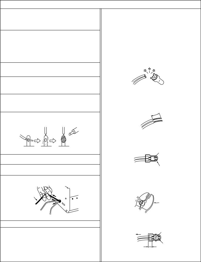
12.Crimp type wire connector
In such cases as when replacing the power transformer in sets where the connections between the power cord and power transformer primary lead wires are performed using crimp type connectors, if replacing the connectors is unavoidable, in order to prevent safety hazards, perform carefully and precisely according to the following steps.
1)Connector part number : E03830-001
2)Required tool : Connector crimping tool of the proper type which will not damage insulated parts.
3)Replacement procedure
(1)Remove the old connector by cutting the wires at a point close to the connector.
Important : Do not reuse a connector (discard it).
cut close to connector
Fig.3
(2)Strip about 15 mm of the insulation from the ends of the wires. If the wires are stranded, twist the strands to avoid frayed conductors.
15 mm
Fig.4
(3)Align the lengths of the wires to be connected. Insert the wires fully into the connector.
Metal sleeve
Connector
Fig.5
(4)As shown in Fig.6, use the crimping tool to crimp the metal sleeve at the center position. Be sure to crimp fully to the complete closure of the tool.
25 |
Crimping tool |
1. |
|
2. |
|
0 |
|
5. |
|
5 |
|
Fig.6
(5) Check the four points noted in Fig.7.
Not easily pulled free |
Crimped at approx. center |
|
|
of metal sleeve |
|
|
|
|
|
|
Conductors extended |
Wire insulation recessed |
|
|
more than 4 mm |
|
|
Fig.7
1 |
S40888-01 |
v Safety Check after Servicing
Examine the area surrounding the repaired location for damage or deterioration. Observe that screws, parts and wires have been returned to original positions, Afterwards, perform the following tests and confirm the specified values in order to verify compliance with safety standards.
1.Insulation resistance test
Confirm the specified insulation resistance or greater between power cord plug prongs and externally exposed parts of the set (RF terminals, antenna terminals, video and audio input and output terminals, microphone jacks, earphone jacks, etc.). See table 1 below.
2.Dielectric strength test
Confirm specified dielectric strength or greater between power cord plug prongs and exposed accessible parts of the set (RF terminals, antenna terminals, video and audio input and output terminals, microphone jacks, earphone jacks, etc.). See table 1 below.
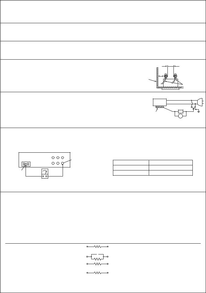
3.Clearance distance
When replacing primary circuit components, confirm specified clearance distance (d), (d’) between soldered terminals, and between terminals and surrounding metallic parts. See table 1 below.
Chassis
Fig. 8
d |
d' |
Power cord, |
primary wire |
4.Leakage current test
Confirm specified or lower leakage current between earth ground/power cord plug prongs and externally exposed accessible parts (RF terminals, antenna terminals, video and audio input and output terminals, microphone jacks, earphone jacks, etc.).
Measuring Method : (Power ON)
Insert load Z between earth ground/power cord plug prongs and externally exposed accessible parts. Use an AC voltmeter to measure across both terminals of load Z. See figure 9 and following table 2.
|
a |
b |
Externally |
Z |
c |
|
|
|
exposed |
V |
|
accessible part |
|
|
|
Fig. 9 |
|
5.Grounding (Class 1 model only)
Confirm specified or lower grounding impedance between earth pin in AC inlet and externally exposed accessible parts (Video in, Video out, Audio in, Audio out or Fixing screw etc.).
Measuring Method:
Connect milli ohm meter between earth pin in AC inlet and exposed accessible parts. See figure 10 and grounding specifications.
AC inlet |
Grounding Specifications |
|
Exposed accessible part |
Grounding Impedance (Z) |
|
|
Region |
|
|
USA & Canada |
Z ≤ 0.1 ohm |
Earth pin |
Europe & Australia |
Z ≤ 0.5 ohm |
Milli ohm meter
Fig. 10
AC Line Voltage |
Region |
|
Insulation Resistance (R) |
Dielectric Strength |
Clearance Distance (d), (d') |
||||||||||||
|
|
|
|
|
|
|
|
|
|
|
|
|
|
|
|||
100 V |
Japan |
|
R |
£ |
1 MΩ/500 V DC |
AC 1 kV 1 minute |
|
d, d' |
£ |
3 mm |
|||||||
100 to 240 V |
|
AC 1.5 kV 1 miute |
|
d, d' |
£ |
4 mm |
|||||||||||
|
|
|
|||||||||||||||
|
|
|
|
|
|
|
|
|
|
||||||||
|
|
|
|
|
|
|
|
|
|
|
|||||||
110 to 130 V |
USA & Canada |
|
1 MΩ |
³ |
R |
³ |
12 MΩ/500 V DC |
AC 1 kV 1 minute |
|
d, d' |
£ |
3.2 mm |
|||||
|
|
|
|
|
|||||||||||||
110 to 130 V |
|
|
|
|
|
|
|
|
|
AC 3 kV 1 minute |
d |
£ |
4 mm |
|
|||
Europe & Australia |
|
R |
£ 10 MΩ/500 V DC |
|
|
(Class 2) |
d' |
£ |
8 mm (Power cord) |
||||||||
200 to 240 V |
|
|
|
||||||||||||||
|
|
|
|
|
|
|
|
|
AC 1.5 kV 1 minute |
d' |
£ |
6 mm (Primary wire) |
|||||
|
|
|
|
|
|
|
|
|
|
|
|
(Class 1) |
|||||
|
|
|
|
|
|
|
|
|
|
|
|
|
|||||
|
|
Table 1 Specifications for each region |
|
|
|
|
|
|
|||||||||
|
|
|
|
|
|
|
|
|
|
|
|
|
|
||||
AC Line Voltage |
Region |
|
|
|
|
Load Z |
Leakage Current (i) |
|
|
|
a, b, c |
||||||
100 V |
Japan |
|
|
|
|
|
1 kΩ |
i |
≤ |
1 mA rms |
Exposed accessible parts |
||||||
|
|
|
|
|
|
|
|
|
|
|
|
|
|
|
|||
|
|
|
|
|
|
|
|
|
|
|
|
|
|
|
|
||
110 to 130 V |
USA & Canada |
|
0.15 F |
|
|
|
1.5 kΩ |
i |
≤ |
0.5 mA rms |
Exposed accessible parts |
||||||
|
|
|
|
||||||||||||||
|
|
|
|
|
|
|
|||||||||||
|
|
|
|
|
|
|
|
|
|
|
|
|
|
|
|
|
|
|
|
|
|
|
|
|
|
|
|
i |
≤ |
0.7 mA peak |
Antenna earth terminals |
||||
110 to 130 V |
Europe & Australia |
|
|
|
|
|
2 kΩ |
i |
≤ |
2 mA dc |
|||||||
220 to 240 V |
|
|
|
|
|
|
|
|
i |
≤ |
0.7 mA peak |
Other terminals |
|||||
|
|
|
|
|
|
|
|
|
|||||||||
|
|
|
|
|
|
|
50 kΩ |
i ≤ |
2 mA dc |
||||||||
|
|
|
|
|
|
|
|
|
|
|
|
||||||
Table 2 Leakage current specifications for each region
Note: These tables are unofficial and for reference only. Be sure to confirm the precise values for your particular country and locality.
2 |
S40888-01 |
|
SECTION 1
DISASSEMBLY
1.1 HOW TO REMOVE THE MAJOR PARTS
1.1.1 Introduction
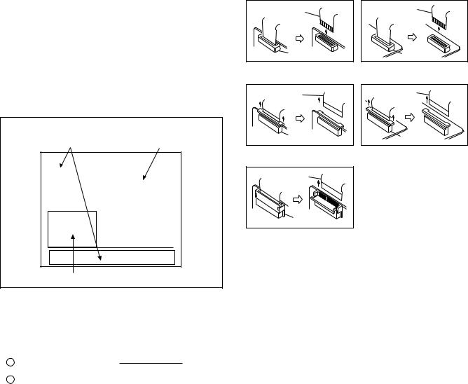
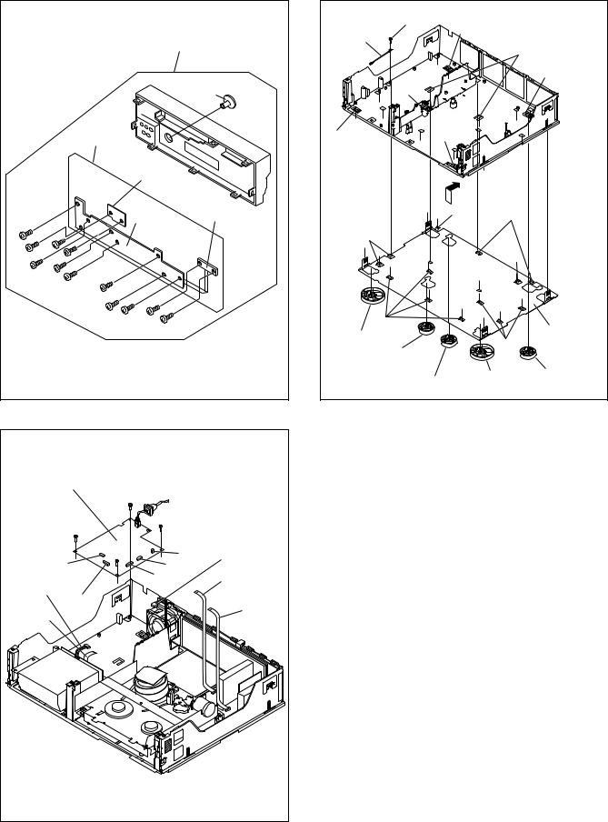
This set is a double-deck video recorder integrating a Mini DV deck and a VHS deck. Its internal structure is divided into three sections that include the power supply, VHS and DV sections. Therefore, the removal of major parts will also be described under three separate sections as listed below.
1.COMMON section
2.VHS section
3.DV section
<TOP VIEW >
1. COMMON section |
2. VHS section |
||||
|
|
|
|
|
|
|
|
|
|
|
|
|
|
|
|
|
|
|
|
|
|
|
|
3. DV section
Fig. 1-1-1
1.2 HOW TO READ THE DISASSEMBLY AND ASSEMBLY
Step/ |
Part name |
Fig. No. |
Point |
Note |
|
Loc No. |
|||||
|
|
|
|
||
|
|
|
|
|
|
1 |
Top cover, Bracket |
COM1 |
4(S1), 3(S2), 2(L1), (L2) |
— |
|
2(S3) |
|||||
2 |
Front panel |
COM2 |
8(L3), |
<Note |
|
|
assembly |
|
CN7507(WR1), |
1,2,3,4> |
|
|
|
|
CN3011(WR2) |
|
|
|
|
|
|
|
|
§ |
§ |
§ |
§ |
§ |
|
(1) |
(2) |
(3) |
(4) |
(5) |
(1)Order of steps in Procedure
When reassembling, perform the step(s) in the reverse order. These numbers are also used as the identification (location) No. of parts Figures.
(2)Part name to be removed or installed.
(3)Fig. No. showing procedure or part location.
(4)Identification of part to be removed, unhooked, unlocked, released, unplugged, unclamped or unsoldered.
P= Spring, W= Washer, S= Screw, L= Locking tab, SD= Solder, CN**(WR**)= Remove the wire (WR**) from the connector (CN**).
Note:
• The bracketed ( ) WR of the connector symbol are assigned nos. in priority order and do not correspond to those on the spare parts list.
(5) Adjustment information for installation
1.3 DISCONNECTION OF CONNECTORS (WIRES)
FPC
CONNECTOR |
Fig. 1-3-1 |
FPC |
CONNECTOR |
Fig. 1-3-3 |
FPC |
CONNECTOR |
Fig. 1-3-5 |
FPC |
CONNECTOR |
Fig. 1-3-2 |
FPC |
CONNECTOR |
Fig. 1-3-4 |
1-1
1.4 HOW TO REMOVE THE MAJOR PARTS <COM section>
1.4.1 Disassembly flow chart
This flowchart shows the disassembly procedure for the exterior parts and electrical parts.
Basically, reverse this procedure when assembling them.
[1] |
Top cover, Bracket |
|
|
|
|
|
|
|
[2] |
Front panel assembly |
|
|
|
|
|
|
|
SW/Display board assembly, Power SW board assembly,
[3]Jog board assembly
[4]SW REG board assembly
[5]Foot assembly, Foot(center), Foot(rear), Bottom cover
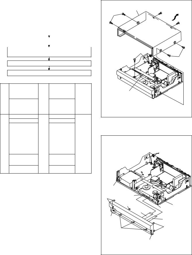
1.4.2 Disassembly/assembly method <COM section>
Step/ |
Part name |
Fig. No. |
Point |
Note |
|
Loc No. |
|||||
|
|
|
|
||
|
|
|
|
|
|
|
Top cover |
COM1 |
4(S1a), 2(S1b) |
— |
|
[1] Bracket |
2(S1c) |
||||
[2] |
Front panel |
COM2 |
8(L2a), |
<Note 2a, |
|
assembly |
|
CN7510(WR2a), |
2b, 2c,2d> |
||
|
|
||||
|
|
|
CN3011(WR2b) |
|
|
[3]SW/Display board assembly COM3 8(S3a)
|
Power SW board assembly |
|
2(S3b) |
— |
|
Jog board assembly |
|
2(S3c),Knob(Jog) |
|
|
|
|
|
|
[4] |
SW REG board |
COM4 |
4(S4a), |
<Note 2a> |
assembly |
|
CN5322(WR4a), |
|
|
|
|
|
||
|
|
|
CN5321(WR4b), |
|
|
|
|
CN5325(WR4c), |
|
|
|
|
CN5324(WR4d), |
|
|
|
|
CN5323(WR4e) |
|
|
|
|
|
|
[5] |
Lug wire |
COM5 |
(S5a) |
<Note 5a> |
Foot assembly |
|
5(L5a) |
|
|
|
|
|
||
|
Foot(center) |
|
|
|
|
Foot(rear) |
|
|
|
|
Bottom cover |
|
4(L5b), 9(L5c), |
|
|
|
|
2(L5d) |
|
<Note 2a>
•When attaching the FPC, be sure to connect it in the correct orientation.
•When attaching the FPC take care that it is not caught.
•When removing or attaching the WIRE/FPC, refer to "1.7 CONNECTION"(page 1-8) at same time.
<Note 2b>
When attaching the Front panel assembly, make sure that the door openers of both decks (DV, VHS) are in the down position.
<Note 2c>
When attaching the Front panel assembly, be careful not to damage the DV terminals.
<Note 2d>
When attaching (WR2a) and (WR2b), insert supporting long side to connector in the Main board assembly.
<Note 3a>
When attaching Jog board assembly, attach it before SW/ Display board assembly.
<Note 5a>
When removing Bottom cover, remove it after VHS section parts and DV section parts.
1-2
[1] Top cover |
(S1b) |
(S1a) |
(S1b) |
(S1c) |
(S1a) |
[1] Bracket |
Fig. COM1
<Note 2b> |
|
|
DV SIDE |
|
|
(L2a) |
CN3011 |
|
|
(L2a) |
<Note 2b> |
|
VHS SIDE |
|
|
(WR2b) |
|
|
CN7510 |
|
|
<Note 2a, 2b> |
|
|
|
|
DV terminals |
|
(WR2a) |
<Note 2c> |
|
<Note 2a, 2d> |
(L2a) |
|
(L2a) |
|
|
|
|
[2] Front panel assembly |
|
Fig. COM2
|
|
[2] Front panel assembly |
|
|
Knob (Jog) |
|
[3] |
|
|
|
Jog board assembly |
|
|
<Note 3a> |
|
|
Power SW board |
|
|
assembly |
(S3a) |
|
SW/Display board |
|
assembly |
|
|
|
|
(S3a) |
(S3c) |
|
|
(S3c) |
|
(S3a) |
(S3a) |
|
|
|
|
|
(S3a) |
|
|
(S3a) |
|
|
(S3a) |
|
|
(S3a) |
(S3b) |
|
|
|
|
|
(S3b) |
Fig. COM3
[4] SW.REG board assy |
|
|
(S4a) |
|
|
(S4a) |
(S4a) |
|
(S4a) |
CN5325 (WR4c) |
|
CN5324 |
CN5322 |
<Note 2a> |
(WR4d) |
CN5321 |
(WR4a) |
|
<Note 2a> |
|
<Note 2a> |
|
|
CN5323 |
|
(WR4b) |
(WR4e) |
|
<Note 2a> |
<Note 2a> |
|
|
|
|
|
Fig. COM4
|
(S5a) |
|
|
[5] Lug wire |
(L5a) |
|
|
|
|
|
|
|
|
(L5d) |
|
|
|
|
(L5a) |
|
(L5a) |
|
|
(L5a) |
(L5a) |
|
|
|
(L5b) |
(L5c) |
|
|
|
|
|
(L5b) |
|
|
|
|
|
(L5b) |
|
(L5c) |
|
|
[5] Bottom cover |
[5] Foot assy |
|
|
|
|
(L5c) |
|
|
[5] Foot(center) |
|
||
|
|
||
|
[5] Foot(rear) |
[5] Foot assy |
[5] Foot(rear) |
|
|
||
Fig. COM5
1-3
1.5 HOW TO REMOVE THE MAJOR PARTS <VHS section>
1.5.1 Disassembly flow chart
This flowchart shows the disassembly procedure for the exterior parts and electrical parts.
Basically, reverse this procedure when assembling them. However, it is required to remove the common section parts as far as [1] “Top cover Bracket” and [2] “Front panel assembly” in advance. (See section 1.4.)
[1] |
Drum assembly |
|
|
|
|
|
|
|
[2] |
Mechanism assembly |
|
|
|
|
|
|
|
[3] |
Main board assembly |
|
|
|
|
1.5.2 DIsassembly/assembly method <VHS section>
Step/ |
Part name |
Fig. No. |
Point |
Note |
|
Loc No. |
|||||
|
|
|
|
||
|
|
|
|
|
|
[1] |
Drum assembly |
V1 |
CN1(WR6a), |
<Note 1a,1b> |
|
|
|
|
CON1(WR6b), |
|
|
|
|
|
(S6a), (S6b), (S6c) |
|
|
|
(Inertia plate) |
|
4(L6a) |
|
|
|
(Roller arm assy) |
|
(P6a), (L6b) |
|
|
|
|
|
|
|
|
[2] |
Mechanism |
V2 |
(S7a), (S7b), (S7c), |
<Note 1b, |
|
|
assembly |
|
(S7d), 2(L7a), |
2a, 2b, 2c> |
|
|
|
|
CN1(WR7a) |
|
|
|
|
|
|
|
|
[3] |
Main board |
V3 |
(S8a), 6(L8a), |
<Note 1b> |
|
|
assembly |
|
CN701(WR8a), |
|
|
|
|
|
CN2601(WR8b), |
|
|
|
|
|
CN3014(WR8c) |
|
|
|
|
|
|
|
<Note 1a>
When attaching or removing the FPC, take care not to disconnect any of the wires.
<Note 1b>
•When attaching the FPC, be sure to connect it in the correct orientation.
•When removing or attaching the WIRE/FPC, refer to "1.7 CONNECTION"(page 1-8) at same time.
<Note 2a>
When it is required to remove the screws ((S7a), (S7b), (S7c) and (S7d)) retaining the Mechanism assembly, please refer to the “Procedures for Lowering the Cassette holder assembly”(See on page 1-4).
<Note 2b>
•When reattaching the Mechanism assembly to the Main board assembly, take care not to damage the sensors on the Main board assembly (D3001: LED, Q3002: Start sensor, Q3003: End sensor, S3002: S cassette switch).
•When reattaching the Mechanism assembly to the Main board assembly, CN2 of LOADING MOTOR BOARD should not be floated.
<Note 2c>
•When removing the Mechanism assembly only, unhook the two spacers connecting it with the Main board assembly with pliers from the back side of the Main board assembly first, and then remove the Mechanism assembly.
Procedures for Lowering the Cassette holder assembly
As the mechanism of this unit is integrated with the Housing assembly, the holder must be lowered and the two screws unscrewed when removing the Mechanism assembly.
Fig. 2
Fig. 1
Fig. 3
Turn the loading motor pulley in the direction as indicated by Fig.2. As both A and B levers are lodged twice, push the levers in the direction as indicated by Fig.3 to release them. When pushing the levers, do it in the order of A , B , B , A . When the holder has been lowered, turn the pulley until the cassette holder is securely in place without allowing any up/ down movement.
Procedures for Lowering the Cassette holder assembly
Note: When installing the Drum assembly, secure the screws (S6a to S6c) in the order of a, b, c.
Inertia plate
(S6a) (S6c)
(WR6b) (L6a) <Note 1b>
CON1
 (P6a)
(P6a)
(S6b) |
(WR6a) |
|
<Note 1a,1b> |
||
|
||
(L6b) |
|
|
|
Cleaner assy |
Roller arm assy
[1]
Drum (L6c) assembly
Not used
CN1
Fig. V1
1-4
Note:
Make a crease on the position where the dotted line is not exceeded.
(WR7a)
A/C head base
[2] |
(S7d) |
Mechanism |
|
assembly |
|
(S7b) <Note 2a>
Q3003
D3001
(L7a)
spacer Q3003 <Note 2c> End sensor
<Note 2b>
Note: |
|
|
|
|
When installing the |
|
|
||
Mechanism assembly, |
|
(L8a) |
||
secure the screws |
CN2601 |
|||
(S7a to S7b) in the |
CN701 |
(S8a) |
||
order of a, b. |
(L8a) |
|||
|
||||
|
|
CN3014 |
|
|
(WR7a) |
|
|
||
<Note 1b> |
|
|
||
|
CN2 |
(WR8c) |
[3] Main board |
|
|
<Note 2b> |
<Note 1b> |
||
CN2 |
|
(WR8b) |
assembly |
|
|
|
<Note 1b> |
|
|
|
(S7c) |
(WR8a) |
|
|
|
<Note 1b> |
|
||
|
|
|
||
(S7a) |
D3001 |
|
|
|
<Note 2a> |
LED |
|
|
|
|
<Note 2b> |
|
|
|
CN1 |
|
|
|
|
|
(L7a) |
|
|
|
Q3002 |
spacer |
Fig. V3 |
|
|
|
|
|||
|
<Note 2c> |
|
||
S3002 |
|
|
||
Q3002
Start sensor
<Note 2b>
S3002
S cassette switch <Note 2b>
Fig. V2
1-5

1.6 HOW TO REMOVE THE MAJOR PARTS <DV section>
1.6.1 Disassembly flow chart
This flowchart shows the disassembly procedure for the exterior parts and electrical parts.
Basically, reverse this procedure when assembling them. However, it is required to remove the common section parts as far as [1] “Top cover, Bracket” and [2] “Front panel assembly” in advance. (See section 1.5.)
[1] |
Base(DV) |
|
|
|
|
|
|
|
[2]DV Mechanisam assembly, DV Main board assembly
[3]DV MDA board assembly
1.6.2 Disassembly/assembly method <DV section>
Step/ |
Part name |
Fig. No. |
Point |
Note |
|
Loc No. |
|||||
|
|
|
|
||
|
|
|
|
|
|
[1] |
Base(DV) |
D1 |
3(S9a), (S9b) |
<Note 1a> |
|
|
|
|
|
|
|
[2] |
DV Mechanism |
D2 |
3(S10a), |
<Note 2a, |
|
|
assembly |
|
CN1502(WR10a), |
2b, 2c> |
|
|
|
|
CN4001(WR10b) |
|
|
|
|
|
CN1501(WR10c) |
|
|
|
DV Main board |
|
4(S10b) |
|
|
|
assembly |
|
|
|
|
[3] |
DV MDA board |
D3 |
2(S11a), 2(S11b), |
<Note 2c> |
|
|
assembly |
|
2(L11a), |
|
|
|
|
|
CN5503(WR11a), |
|
|
|
|
|
CN5504(WR11b), |
|
|
|
|
|
CN5502(WR11c), |
|
|
|
|
|
CN5505(WR11d), |
|
|
|
|
|
CN5507(WR11e), |
|
|
|
|
|
Bracket(MDA) |
|
|
|
|
|
|
|
<Note 1a>
With due regard to operational considerations, remove the parts located on the Base(DV) (i.e. DV Mechanism assembly, DV MDA board assembly etc.) together before removing the major parts.
<Note 2a>
Take care not to scratch or damage the drum assembly by the cleaner assembly when performing work.
<Note 2b>
Take care not to damage the board assembly when detaching parts.
<Note 2c>
•When attaching the FPC, be sure to connect it in the correct orientation.
•When removing or attaching the WIRE/FPC, refer to "1.7 CONNECTION"(page 1-8) at same time.
(S9b)
(S9a)
(S9a)
(S9a)
Lug wire
(S9b) Lug wire
Base(DV)
Bottom chassis
When reattaching (S9b), attach in the order of the above figure.
Fig. D1
[2] Mechanism |
|
(S10a) (WR10c) |
|
(S10a) |
<Note 2c> |
||
assembly(DV) |
(WR10b) |
||
|
|||
<Note 2a> |
|
||
|
<Note 2c> |
||
|
|
||
[1] Base(DV) |
|
(WR10a) |
|
|
|
<Note 2c> |
[2] DV Main |
(S10b) |
|
board assembly |
|
|
<Note 2b> |
|
CN4001 |
|
|
|
|
|
CN4001 |
|
CN1502 |
CN1501 |
|
(S10b) |
|
CN1502 |
(S10b) |
|
Fig. D2
1-6
5
(S11a)
[3] DV MDA board assembly
NOTE: When removing, remove in order of a number |
1 to 5 . |
5
(S11a)
 3 (S11b)
CN5504
3
Bracket(DV)
(S11b) |
|
|
|
|
|
(WR11d) 1 |
4 |
|
|
<Note 2c> |
(WR11a) |
|
CN5502 |
CN5505 |
<Note 2c> |
|
CN5503 |
CN5507 |
|
2 |
|
||
|
|
||
|
|
|
|
(WR11b) |
|
|
1 |
<Note 2c> |
|
|
(WR11e) |
3 |
|
|
<Note 2c> |
|
|
|
|
(L11a) |
1 |
|
|
|
(WR11c) |
|
|
|
<Note 2c> |
|
|
Fig. D3
1-7

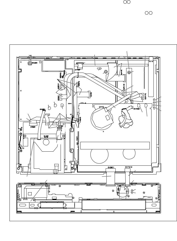
1.7 CONNECTION
16
FAN
5
Treat the wire so as not to come to fan.
bend
right side
6 |
|
7 |
|
|
|
|
|
11 |
|
|
bend |
bend |
|
|
|
|
|
|
|
|
|
CN5323 |
|
|
CN1001 |
CN3701 |
|
right side |
right side |
CN1501 |
|
|
|
18 |
|
CN5501 |
|
14 |
CN5506 |
|
|
||
back side
DV DRUM
CN1502
B
17
CN901 |
right side |
CN502 |
right side |
TERMINAL PWB
Hold wire by stylepin.
3
ST2
12 |
|
right side |
|
|
|
15 |
|
right side |
|
make a crease |
|
|
|
||
|
4 |
|
|
8 |
|
|
right side |
|
|
CN3001 |
|
|
|
|
|
CN1 |
|
right side |
|
A |
|
10 |
|
13 |
9 |
|
|
|
|
||
DRUM
back side
right side
bend
A/C HEAD
Should be confirmed that wire not touch to IC of STATOR PWB ASS'Y.
2 |
1 |
|
back side
back side |
C |
|
|
To SW/Display board |
To SW/Display board |
CN7001 |
CN7191 |
NOTE) Wire the wires as shown in a figure.
NOTE) Wire the wires as shown in a figure.
NOTE) Put the surplus
wire into this space. NOTE) Twist a wire one time.
"D"
CN5502 CN5505 CN5503
|
CN5507 |
22 |
20 |
|
|
21 |
19 |
|
NOTE) Wire the wires as shown in a figure.
Fig. 1-7-1
1-8
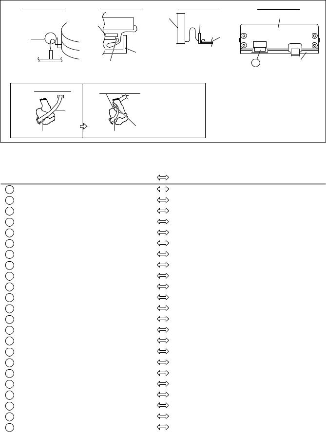
DETAIL"A" |
DETAIL"B" |
DETAIL"C" |
Absorb the looseness of the wire in the B part.
|
DV MAIN |
DV MECHA |
|
PWB |
|
|
|
|
B |
DRUM |
|
|
CN1502 |
|
CN1 |
|
BOTTOM |
|
CHASSIS |
|
MAIN PWB |
|
electrode side |
|
|
|
|
Push into the BOTTOM CHASSIS |
|
|
and treat the wire according |
|
|
to the following figure. |
|
WIRING for MECHA ADJ |
FINAL WIRING |
|
FRONT PANEL
BOTTOM CHASSIS
CN7510 MAIN PWB
CN3011
Absorb the looseness of the wire according to the following figure.
AC/ HEAD |
AC/ HEAD |
|
After MECHA adjustment, |
|
(WR7a) |
|
Treat the wire (WR7a) according |
|
|
to the following figure. |
|
|
|
|
|
|
|
|
Make a crease on the position where |
right side |
|
right side |
the dotted line is not exceeded. |
|
|
DETAIL "D"
DV MDA BOARD ASSEMBLY
CN5504
23 BRACKET(DV)
Fig. 1-7-2
Fig |
|
|
|
Connection |
|
|
|
Pin |
Type |
||
Symbol |
|
|
|
|
|
|
|
|
(FPC/ |
||
No. |
Connected point |
|
|
|
|
Connected point |
|
|
No. |
||
|
|
|
|
|
|
|
|
|
WIRE) |
||
1 |
WR2a |
MAIN |
|
CN7510 |
|
|
SW/DISPLAY |
|
CN7191 |
10 |
FPC |
|
|
|
|
||||||||
|
|
|
|
|
|
|
|
|
|
|
|
2 |
WR2b |
MAIN |
|
CN3011 |
|
|
SW/DISPLAY |
|
CN7001 |
20 |
FPC |
|
|
|
|
|
|
|
|
|
|
|
|
3 |
WR4a |
MAIN |
|
CN7508 |
|
|
SW/REG |
|
CN5322 |
10 |
FPC |
|
|
|
|
|
|
|
|
|
|
|
|
4 |
WR4b |
MAIN |
|
CN7509 |
|
|
SW/REG |
|
CN5321 |
12 |
FPC |
|
|
|
|
|
|
|
|
|
|
|
|
5 |
WR4c |
SW/REG |
|
CN5325 |
|
|
FAN MOTOR |
|
- |
2 |
WIRE |
|
|
|
|
|
|
|
|
|
|
|
|
6 |
WR4d |
SW/REG |
|
CN5324 |
|
|
DV MDA |
|
CN5501 |
5 |
WIRE |
|
|
|
|
|
|
|
|
|
|
|
|
7 |
WR4e |
SW/REG |
|
CN5323 |
|
|
DV MAIN |
|
CN1001 |
8 |
FPC |
|
|
|
|
|
|
|
|
|
|
|
|
8 |
WR6a |
MAIN |
|
CN1 |
|
|
UPPER DRUM |
|
- |
13 |
FPC |
|
|
|
|
|
|
|
|
|
|
|
|
9 |
WR6b |
DRUM MOTOR |
|
CON1 |
|
|
MAIN |
|
CN3001 |
5 |
FPC |
|
|
|
|
|
|
|
|
|
|
|
|
10 |
WR7a |
A/C HEAD |
|
CN1 |
|
|
MAIN |
|
CN2001 |
7 |
FPC |
|
|
|
|
|
|
|
|
|
|
|
|
11 |
WR8a |
MAIN |
|
CN701 |
|
|
DV MAIN |
|
CN3501 |
14 |
FPC |
|
|
|
|
|
|
|
|
|
|
|
|
12 |
WR8b |
MAIN |
|
CN2601 |
|
|
DV MAIN |
|
CN3701 |
8 |
FPC |
|
|
|
|
|
|
|
|
|
|
|
|
13 |
WR8c |
MAIN |
|
CN3014 |
|
|
DV MAIN |
|
CN1503 |
4 |
FPC |
|
|
|
|
|
|
|
|
|
|
|
|
14 |
WR10c |
DV MAIN |
|
CN1501 |
|
|
DV MDA |
|
CN5506 |
20 |
FPC |
|
|
|
|
|
|
|
|
|
|
|
|
15 |
- |
MAIN |
|
CN7506 |
|
|
TERMINAL |
|
CN502 |
15 |
FPC |
|
|
|
|
|
|
|
|
|
|
|
|
16 |
- |
MAIN |
|
CN7507 |
|
|
TERMINAL |
|
CN901 |
9 |
FPC |
|
|
|
|
|
|
|
|
|
|
|
|
17 |
WR10a |
SENSOR(DV) |
|
- |
|
|
DV MAIN |
|
CN1502 |
15 |
FPC |
|
|
|
|
|
|
|
|
|
|
|
|
18 |
WR10b |
PRE/REC(DRUM)(DV) |
|
- |
|
|
DV MAIN |
|
CN4001 |
8 |
FPC |
|
|
|
|
|
|
|
|
|
|
|
|
19 |
WR11a |
DRUM MOTOR(DV) |
|
- |
|
|
DV MDA |
|
CN5503 |
11 |
FPC |
|
|
|
|
|
|
|
|
|
|
|
|
20 |
WR11e |
HOUSING MOTOR(DV) |
|
- |
|
|
DV MDA |
|
CN5507 |
4 |
WIRE |
|
|
|
|
|
|
|
|
|
|
|
|
21 |
WR11d |
ROTARY ENCODER(DV) |
|
- |
|
|
DV MDA |
|
CN5505 |
4 |
WIRE |
|
|
|
|
|
|
|
|
|
|
|
|
22 |
WR11c |
LOADING MOTOR(DV) |
|
- |
|
|
DV MDA |
|
CN5502 |
2 |
WIRE |
|
|
|
|
|
|
|
|
|
|
|
|
23 |
WR11b |
CAPSTAN MOTOR(DV) |
|
- |
|
|
DV MDA |
|
CN5504 |
18 |
FPC |
Table 1-7-1
1-9

1.8 SERVICE POSITIONS
The servicing locations for use in troubleshooting or servicing of the set are provided separately for the VHS and DV.
I SERVICE POSITIONS <VHS SIDE>
II SERVICE POSITIONS <DV FOIL SIDE>
III SERVICE POSITIONS <DV COMPONENT SIDE>
1.8.1 Requirement PATCH CORDS
The following PATCH CORDS is required.
|
Board to Board |
Wire |
Used |
|
|
|
|
1 |
PTU94022-10 |
QUQ212-1040CG |
I |
2 |
PTU94022-20 |
QUQ112-2040CG |
I |
3 |
YTU94074-15 |
QUQ105-1540AA |
III |
|
|
|
|
Table 1-8-1
1.8.2 Service position <VHS SIDE>
<Removal>
(1)Remove the top cover and bracket.
(2)Remove the front panel assembly.
(3)Remove the Main board assembly together with the Mechanism assembly.
< Installation >
(1)Stand up the Bottom chassis assembly so that the DV/ Regulator side is in the lower position.
Note: • Take care to the fall of the Fan.
(2)Connect FPCs and wires accordingly in Fig. 1-8-1.
Point: • Take care that the FPCs and wires are not subjected to stress in this positioning.
(3)Connect the PATCH CORDS to the two FPCs of the Front panel assembly, then connect the CORDS to the CN7510/CN3011.
For the PATCH CORD is required, see Table 1-8-1.
|
CN5322 |
|
|
CN5321 |
CN1503 |
|
|
|
|
|
CN3701 |
CN2601 |
|
CN3501 |
|
|
|
CN701 |
|
1 |
|
|
|
CN7508 |
|
|
CN7509 |
CN3011 |
|
|
|
|
|
CN3014 |
2 |
|
|
|
|
CN7510 |
CN7191 |
Main board assembly |
CN7001 |
|
|
|
Front panel assembly |
|
Fig. 1-8-1 |
|
1.8.3 Service position <DV FOIL SIDE>
<Removal>
(1)Remove the top cover and bracket.
(2)Remove the front panel assembly.
(3)Remove the Base(DV) together with DV Mechanism assembly and DV Main board assembly.
Note:
• Take care not to damage the parts during operating.
< Installation >
(1)Place an insulation sheet on the SW/Reg board assembly.
(2)Place a DV section(Base(DV) with DV Mechanism assembly and DV Main board assembly) on the insulation sheet.(refer to Fig. 1-8-2)
Note:
• Confirm that FPCs and wires are not unconnected from the connectors.
DV Mechanism |
|
|
assembly |
CN2601 |
|
Insulation Sheet |
||
CN701 |
||
DV Main board |
|
|
assembly |
|
|
CN1502 |
CN3014 |
|
|
||
CN3501 |
|
|
Base(DV) |
CN3011 |
|
CN3701 |
CN7510 |
|
CN1503 |
||
|
Front panel assembly |
CN7001 |
CN7191 |
|
|
Fig. 1-8-2
1-10
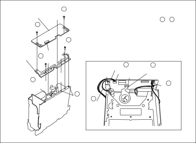
1.8.4 Service position <DV COMPONENT SIDE>
<Removal>
(1)Remove the top cover and bracket.
(2)Remove the front panel assembly.
(3)Remove the Base(DV) together with DV Mechanism assembly and DV Main board assembly.
(4)Remove the DV Mechanism assembly and DV Main board assembly from Base(DV).
Note:
• Take care not to damage the parts during operating.
< Installation >
(1)Place a DV Main board assembly on the Bottom chassis.
(2)Place an insulation sheet on the rear side of DV Main board assembly.
(3)Place a DV Mechanism assembly on the insulation sheet.
Note:
• Confirm that DV Mechanism assembly be getting on on the insulation sheet completely.
(4)Connect PATCH CORD to the connector(CN1502) and connect FPC from DV Mechanism assembly.(refer to Fig. 1-8-3)
(5)Connect other FPCs and wires to the connector that corresponds each.(refer to "1-7 CONNECTION")
For the PATCH CORD is required, see Table 1-8-1.
Note:
• Confirm that FPCs and wires are not unconnected from the connectors(especially CN4001).
DV Mechanism |
|
|
assembly |
|
|
Insulation Sheet |
|
|
3 |
|
CN1502 |
|
|
|
|
|
CN3011 |
CN4001 |
|
CN7510 |
DV Main board |
|
|
assembly |
|
|
Front panel assembly |
CN7001 |
CN7191 |
Fig. 1-8-3 |
|
|
1.9Jig RCU mode
This unit uses the following two modes for receiving remote control codes.
1) |
User RCU mode : Ordinary mode for use by the user. |
2) |
Jig RCU mode : Mode for use in production and serv- |
|
icing. |
When using the Jig RCU, it is required to set the VCR to the Jig RCU mode (the mode in which codes from the Jig RCU can be received). As both of the above two modes are stored in the EEPROM, it is required to set the VCR back to the User RCU mode each time that an adjustment is made or to check that the necessary operations have been completed. These modes can be set by the operations described below.
1.9.1Setting the Jig RCU mode
(1)Unplug the power cord plug from the power outlet.
(2)Press and hold the “REC” and “PAUSE” buttons on the VCR simultaneously, while plugging the power cord plug into the power outlet.
When the VCR is set to the Jig RCU mode, the symbols ( “ : ” ) in the time display of the FDP are turned off.
1.9.2 Setting the User RCU mode
(1)Turn off the power.
(2)Press the “REC” and “PAUSE” buttons of the VCR simultaneously. Alternatively, transmit the code “80” from the Jig RCU.
1-11
1.10 MECHANISM SERVICE MODE
This model has a unique function to enter the mechanism into every operation mode without loading of any cassette tape. This function is called the “MECHANISM SERVICE MODE”.
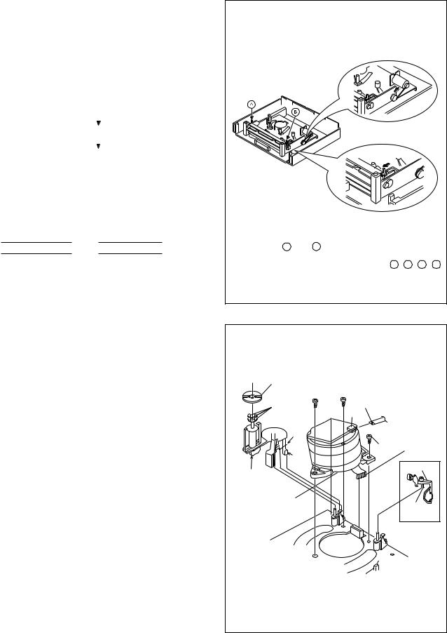
1.10.1 How to set the "MECHANISM SERVICE MODE"
(1)Disconnect VCR from AC.
(2)Connect TPGND and TP7001 (TEST) on the Display board assembly with a jump wire.
(3)Connect VCR to AC.
(4)Press the POWER button.
(5)With lock levers A B on the left and right of the Cassette holder assembly pulled toward the front, slide the holder in the same direction as the cassette insertion direction. (For the positions of lock levers A B , refer to the “Procedures for Lowering the Cassette holder assembly” on page 1-4 of 1.5 HOW TO REMOVE THE MAJOR PARTS <VHS section>
(6)The cassette holder lowers and, when the loading has completed, the mechanism enters the desired mode.
|
|
|
|
|
3D DIGITAL/2M BOARD ASSEMBLY |
|
|
|||
|
|
|
|
|
TERMINAL BOARD ASSEMBLY |
|
|
DEMOD BOARD |
|
|
|
|
|
|
|
|
|
ASSEMBLY |
|
||
|
|
|
|
CN901 |
right side |
CN502 |
right side |
|
|
|
|
|
|
|
|
|
|
|
|
|
|
|
|
FAN |
|
|
|
|
|
|
|
|
|
|
|
|
|
TP701 |
|
|
VR1401 |
|
|
|
|
|
|
|
D YV IN |
|
|
|
|
|
|
|
|
|
|
|
|
|
|
|
|
|
|
|
|
|
VR701 |
|
|
|
|
|
|
|
bend |
|
|
D YV IN |
|
|
|
|
|
|
|
|
ST2 |
|
|
|
|
|
|
|
|
|
|
|
|
|
|
|
|
|
|
SW/REG BOARD |
|
|
|
|
|
|
right side |
|
|
|
ASSEMBLY |
|
|
|
|
|
|
|
|
||
|
|
|
|
|
right side |
|
|
make a crease |
|
|
|
|
|
|
|
|
|
|
|
||
|
|
right side |
|
|
|
|
|
|
|
|
|
|
|
|
|
MAIN BOARD |
|
|
|
|
TP111 |
|
|
|
|
|
ASSEMBLY |
|
|
|
|
D.FF |
|
|
CP5322 |
|
|
|
|
|
|
TP4001 |
|
|
|
|
|
|
|
|
|
right side |
||
|
CP5321 |
|
|
|
|
|
CN3001 |
CTL. P |
||
|
|
|
|
|
|
|
||||
|
|
|
CN1 |
|
CP3004 |
|
|
TP106 |
||
|
|
|
|
|
|
|
|
|||
|
|
|
|
|
|
|
right side |
|
|
PB. FM |
|
|
|
CP5325 |
|
|
|
|
|
|
TP2253 |
bend |
|
bend |
|
|
|
|
CP4001 |
A. PB.FM |
||
|
|
|
|
|
|
|
|
|
||
right side |
|
CN5323 |
|
|
DRUM |
|
|
|
CP3003 |
|
|
|
|
|
|
|
|
|
|||
|
|
|
|
|
|
|
|
|
||
|
CN1001 |
CN3701 |
|
|
back side |
|
|
right side |
|
|
|
|
|
|
|
|
|
|
|||
DV MAIN BOARD |
right side |
CN2001 |
bend |
|
|
|
|
|
||
(JIG CONN.) |
|
|
A/C HEAD |
|
|
|||||
ASSEMBLY |
|
|
CN1501 |
|
|
|
|
|
|
|
|
|
|
|
|
|
|
|
|
|
|
CN5501 |
|
|
CN5506 |
|
|
|
|
|
|
|
|
|
|
|
|
|
|
|
|
|
|
|
|
back side |
|
|
|
|
|
|
|
|
|
DV DRUM |
|
|
|
|
|
|
|
|
|
|
DV MECHANISM |
|
|
|
|
|
|
|
|
|
|
ASSEMBLY |
|
|
|
|
|
|
|
|
|
|
|
CN1502 |
|
|
VHS MECHANISM ASSEMBLY |
|
|
|||
|
|
|
|
|
|
|
||||
|
|
|
|
|
|
|
|
back side |
|
|
DV MDA BOARD |
POWER SW BOARD |
|
|
back side |
|
|
JOG BOARD |
|
|
|
ASSEMBLY |
|
|
|
|
|
ASSEMBLY |
|
|
||
ASSEMBLY |
|
|
|
|
|
|
|
|||
|
|
|
|
|
|
|
|
|
|
|
|
|
FW7001 |
|
|
CN7001 |
|
CN7191 |
|
|
|
|
|
|
|
|
|
|
|
TPGND |
|
|
|
|
|
|
SW/DISPLAY BOARD ASSEMBLY |
|
|
TP7001 |
|
|
|
|
|
|
|
|
|
|
|
TEST |
|
|
FW7002 |
|
|
|
|
|
|
|
|
|
|
|
|
|
|
<FRONT PANEL ASSEMBLY> |
|
|
|
|
|
|
|
|
|
|
|
Fig. 1-10-1 |
|
|
|
|
|
1-12

1.11 Emergency display function
This unit has a function for storing the history of the past two emergencies (EMG) and displaying them on each FDP (or OSD). With the status of the VCR and mechanism at the moment an emergency occurred can also be confirmed.
FDP display model [FDP display]
|
0 : |
00 |
: 00 |
Normal display |
||
|
||||||
|
|
|
EMG content display |
|||
|
E: * * : * * |
|||||
|
|
|
|
|
(E:Latest:Previous) |
|
|
|
|
|
|
||
|
|
|
|
|
||
*1: |
*2 |
: 34 |
EMG detail information <1> |
|||
|
|
|
|
EMG detail information <2> |
||
*5: |
*6 |
: *7 |
||||
|
|
|
|
|
|
|
FDP (7segment LED) display model [FDP display]
 0: 00 Normal display
E: ** EMG content display (Latest)
1:** EMG content display (Previous)
2:*1 EMG detail information <1> [Deck operation mode]
3:*2 EMG detail information <1> [Mechanism operation mode]
4:34 EMG detail information <1>
[Mechanism sensor information and Mechanism mode position] 5: *5 EMG detail information <2>
[Type of the cassette tape in use <1>] 6: *6 EMG detail information <2>
[Winding position of the cassette tape in use] 7: *7 EMG detail information <2>
[Type of the cassette tape in use <2> (Winding area)]
OSD display model [OSD display]
EMG |
|
|
|
|
|
EMG content display |
|
|
|
|
|
|
|||
|
|
|
|
|
(E:Latest:Previous) |
||
E : * * |
: * * |
|
|
|
|
EMG detail information <1> |
|
|
|
|
|
||||
*1: |
*2 |
: 34 |
|
|
|
|
|
|
|
|
|
||||
*5: |
*6 |
: *7 |
|
|
|
|
EMG detail information <2> |
|
|
|
|
||||
|
|
|
|
|
|
|
|
Notes:
•The EMG detail information <1><2> show the information on the latest EMG.
It becomes “ – – : – – : – –” when there is no latest EMG record.
•When using the Jig RCU, it is required to set the VCR to
the Jig RCU mode (the mode in which codes from the Jig RCU can be received).
Jig RCU
[Data transmitting method] Depress the “ ” ( 3 ) button after the data code is set.
INITIAL MODE
CUSTOM CODE 43: A CODE
DATA CODE
Fig. 1-11a Jig RCU [PTU94023B]
1.11.1 Displaying the EMG information
(1)Transmit the code “59” from the Jig RCU.
The FDP shows the EMG content in the form of “E: * * : * * ”.
<Example 1> E : 01 : 03
Previous EMG
Latest EMG
<Example 2> E : – – : – –  No EMG record
(2)Transmit the code “59” from the Jig RCU again.
The FDP shows the EMG detail information <1> in the form of “ * 1 : * 2 : 34 ”.
*1 : Deck operation mode at the moment of EMG
*2 : Mechanism operation mode at the moment of EMG 3– : Mechanism sensor information at the moment of
EMG
–4 : Mechanism mode position at the moment of EMG
(3)Transmit the code “59” from the Jig RCU once again.
The FDP shows the EMG detail information <2> in the form
of “ * 5 : * 6 : * 7 ”.
*5 : Type of the cassette tape in use <1> .
*6 : Winding position of the cassette tape in use
*7 : Type of the cassette tape in use <2> (Winding area)
(4)Transmit the code “59” from the Jig RCU once again to reset the display.
Notes:
•For the OSD display model, all EMG information are showed by transmitting first code from the Jig RCU.
•For the EMG content, see “1.7.3 EMG content description”.
•For the EMG detail information <1> , see “1.7.4 EMG detail information <1> ”.
•For the EMG detail information <2> , see “1.7.5 EMG detail information <2>”.
1.11.2 Clearing the EMG history
(1)Display the EMG history.
(2)Transmit the code “36” from the Jig RCU.
(3)Reset the EMG display.
(EMG-02e)
1-13
1.11.3 EMG content description
Note: EMG contents “E08/E09” are for the model with Dynamic Drum (DD).
FDP |
CONTENT |
|
CAUSE |
E01: Loading EMG |
When the mechanism mode cannot be changed to an- |
1. |
The mechanism is locked in the middle of mode transition. |
|
other mode even when the loading motor has rotated |
2. The mechanism is locked at the loading end due to the encoder position |
|
|
for more than 4 seconds in the loading direction, [E:01] |
|
reading error during mode transition. |
|
is identified and the power is turned off. |
3. |
Power is not supplied to the loading MDA. |
|
|
|
|
E02: Unloading EMG |
When the mechanism mode cannot be changed to an- |
1. |
The mechanism is locked in the middle of mode transition. |
|
other mode even when the loading motor has rotated |
2. |
The mechanism is locked at the unloading end due to the encoder posi- |
|
for more than 4 seconds in the unloading direction, [E:02] |
|
tion reading error during mode transition. |
|
is identified and the power is turned off. |
3. |
Power is not supplied to the loading MDA. |
|
|
|
|
E03: Take Up Reel |
When the take-up reel pulse has not been generated for |
1. |
The take-up reel pulse is not generated in the FWD transport modes (PLAY/ |
Pulse EMG |
more than 4 seconds in the capstan rotating mode, [E:03] |
|
FWD SEARCH/FF, etc.) because; |
|
is identified, the pinch rollers are turned off and stopped, |
|
1) The idler gear is not meshed with the take-up reel gear; |
|
and the power is turned off. However, the reel EMG is |
|
2) The idler gear is meshed with the take-up reel gear, but incapable of wind- |
|
not detected in STILL/SLOW modes. |
|
ing due to too large mechanical load (abnormal tension); |
|
|
|
3) The take-up reel sensor does not output the FG pulse. |
|
|
2. |
The supply reel pulse is not generated in the REV transport modes (REV |
|
|
|
SEARCH/REW, etc.) because; |
|
|
|
1) The idler gear is not meshed with the supply reel gear. |
|
|
|
2) The idler gear is meshed with the supply reel gear, but incapable of wind- |
|
|
|
ing due to too large a mechanical load (abnormal tension); |
|
|
|
3) The supply reel sensor does not output the FG pulse. |
|
|
3. |
Power is not supplied to the reel sensors. |
|
|
|
|
E04: Drum FG |
When the drum FG pulse has not been input for more |
1. |
The drum could not start or the drum rotation has stopped due to too large |
EMG |
than 3 seconds in the drum rotating mode, [E:04] is iden- |
|
a load on the tape, because; |
|
tified, the pinch rollers are turned off and stopped, and |
|
1) The tape tension is abnormally high; |
|
the power is turned off. |
2. |
2) The tape is damaged or a foreign object (grease, etc.) adheres to the tape. |
|
|
The drum FG pulse did not reach the System controller CPU because; |
|
|
|
|
1) The signal circuit is disconnected in the middle; |
|
|
|
2) The FG pulse generator (hall device) of the drum is faulty. |
|
|
3. |
The drum control voltage (DRUM CTL V) is not supplied to the MDA. |
|
|
4. |
Power is not supplied to the drum MDA. |
|
|
|
|
E05: Cassette Eject |
When the eject operation does not complete in 3 sec- |
1. |
The cassette cannot be ejected due to a failure in the drive mechanism of |
EMG |
onds after the start, [E:05] is identified, the pinch rollers |
2. |
the housing. |
|
are turned off and stopped, and the power is turned off. |
When the housing load increases during ejection, the loading motor is |
|
|
When the cassette insertion operation does not complete |
|
stopped because of lack of headroom in its drive torque. |
|
in 3 seconds after the start, the cassette is ejected. In |
|
Housing load increasing factors: Temperature environment (low tempera- |
|
addition, when the operation does not complete within |
|
ture, etc.), mechanism wear or failure. |
|
3 seconds after the start, [E:05] is also identified and the |
3. |
The sensor/switch for detecting the end of ejection are not functioning normally. |
|
power is turned off immediately. |
4. |
The loading motor drive voltage is lower than specified or power is not sup- |
|
|
|
plied to the motor (MDA). |
|
|
5. |
When the user attempted to eject a cassette, a foreign object (or perhaps |
|
|
|
the user's hand) was caught in the opening of the housing. |
|
|
|
|
E06: Capstan FG |
When the capstan FG pulse has not been generated for |
1. |
The capstan could not start or the capstan rotation has stopped due to too |
EMG |
more than 1 second in the capstan rotating mode, [E:06] |
|
large a load on the tape, because; |
|
is identified, the pinch rollers are turned off and stopped, |
|
1) The tape tension is abnormally high (mechanical lock); |
|
and the power is turned off.However, the capstan EMG |
|
2) The tape is damaged or a foreign object (grease, etc.) is adhered to the |
|
is not detected in STILL/SLOW/FF/REW modes. |
2. |
tape (occurrence of tape entangling, etc.). |
|
|
The capstan FG pulse did not reach the System controller CPU because; |
|
|
|
|
1) The signal circuit is disconnected in the middle; |
|
|
|
2) The FG pulse generator (MR device) of the capstans is faulty. |
|
|
3. |
The capstan control voltage (CAPSTAN CTL V) is not supplied to the MDA. |
|
|
4. |
Power is not supplied to the capstan MDA. |
|
|
|
|
E07: SW Power |
When short-circuiting of the SW power supply with GND |
1. |
The SW 5 V power supply circuit is shorted with GND. |
Short-Circuit |
has lasted for 0.5 second or more, [E:07] is identified, |
2. |
The SW 12 V power supply circuit is shorted with GND. |
EMG |
all the motors are stopped and the power is turned off. |
|
|
|
|
|
|
E08: DD Initialized |
When DD tilting does not complete in 4 seconds, [E:08] |
1. |
The absolute value sensor is defective. (The soldered parts have separated.) |
(Absolute |
is identified, the tilt motor is stopped and the power is |
2. |
The pull-up resistor at the absolute sensor output is defective. (The soldered parts |
Position |
turned off. |
|
have separated.) |
Sensor) |
|
3. |
Contact failure or soldering failure of the pins of the connector (board-to-board) to the |
EMG |
|
4. |
absolute value sensor. |
|
|
The absolute value sensor data is not sent to the System Controller CPU. |
|
|
|
|
|
|
When the DD FG pulse is not generated within 2.5 sec- |
1. The FG sensor is defective. (The soldered parts have separated.) |
|
E09: DD FG EMG |
onds, [E:09] is identified, the tilt motor is stopped and |
2. |
The pull-up resistor at the FG sensor output is defective. (The soldered parts have |
|
the power is turned off. |
3. |
separated.) |
|
|
Contact failure or soldering failure of the pins of the connector (board-to-board) to the FG sensor. |
|
|
|
4. |
The power to the sensor is not supplied. (Connection failure/soldering failure) |
|
|
5. |
The FG pulse is not sent to the System Controller CPU. |
|
|
6. |
The tilt motor is defective. (The soldered parts have separated.) |
|
|
7. |
The drive power to the tilt motor is not supplied. (Connection failure/soldering failure) |
|
|
8. |
The tilt motor drive MDA - IC is defective. |
|
|
9. |
Auto-recovery of the DD tilting cannot take place due to overrun. |
|
|
|
|
E0A:Supply Reel |
When the supply reel pulse has not been generated for |
1. |
The supply reel pulse is not generated in the FWD transport mode (PLAY/ |
Pulse EMG |
more than 10 seconds in the capstan rotating mode, |
|
FWD SEARCH/FF, etc.) because; |
|
[E:0A] is identified and the cassette is ejected (but the |
|
1) PLAY/FWD or SEARCH/FF is started while the tape in the inserted cas- |
|
power is not turned off). However, note that the reel EMG |
|
sette is cut in the middle; |
|
is not detected in the SLOW/STILL mode. |
|
2) A mechanical factor caused tape slack inside and outside the supply |
|
|
|
reel side of the cassette shell. In this case, the supply reel will not rotate |
|
|
|
until the tape slack is removed by the FWD transport, so the pulse is not |
|
|
|
generated until then; |
|
|
|
3) The FG pulse output from the supply reel sensor is absent. |
|
|
2. |
The take-up reel pulse is not generated in the REV transport mode (REV |
|
|
|
SEARCH/REW, etc.). |
|
|
|
1) REV SEARCH/REW is started when the tape in the inserted cassette |
|
|
|
has been cut in the middle; |
|
|
|
2) A mechanical factor caused tape slack inside and outside the take-up |
|
|
|
reel side of the cassette shell. In this case, the supply reel will not rotate |
|
|
|
until the tape slack is removed by the REV transport, so the pulse will |
|
|
|
not be generated until that time; |
|
|
|
3) The FG pulse output from the take-up reel sensor is absent. |
|
|
3. |
The power to a reel sensor is not supplied. |
|
|
|
|
EC1 or EU1: |
Presupposing the presence of the control pulse output in the PLAY mode, when the value obtained by mixing the two V.FM output |
||
|
channels (without regard to the A.FM output) has remained below a certain threshold level for more than 10 seconds, [E:C1] or [E:U1] |
||
Head clog warning |
is identified and recorded in the emergency history. During the period in which a head clog is detected, the FDP and OSD repeat the |
||
|
“3-second warning display” and “7-second noise picture display” alternately. |
||
|
EMG code : “E:C1” or “E:U1” / FDP : “U:01” / OSD : “Try cleaning tape.” or “Use cleaning cassette.” |
||
|
The head clog warning is reset when the above-mentioned threshold has been exceeded for more than 2 seconds or the mode is |
||
|
changed to another mode than PLAY. |
|
|
|
|
|
|
1-14 |
Table 1-11-3a |
|
1.11.4 EMG detail information <1>
The status (electrical operation mode) of the VCR and the status (mechanism operation mode/sensor information) of the mechanism in the latest EMG can be confirmed based on the figure in EMG detail information <1> .
[FDP/OSD display]
*1 : * 2 : 34
*1 : Deck operation mode at the moment of EMG
*2 : Mechanism operation mode at the moment of EMG 3– : Mechanism sensor information at the moment of EMG –4 : Mechanism mode position at the moment of EMG
Note:
• For EMG detailed information <1>, the content of the code that is shown on the FDP (or OSD) differs depending on the parts number of the system control microprocessor (IC3001) of the VCR. The system control microprocessor parts number starts with two letters, refer these to the corresponding table.
* 1 : Deck operation mode
[Common table of MN*, HD* and M3*]
Display |
|
Deck operation mode |
|
MN*/M3* |
HD* |
|
|
|
|
||
00 |
- |
|
Mechanism being initialized |
01 |
00 |
|
STOP with pinch roller pressure off (or tape present with P.OFF) |
02 |
01 |
|
STOP with pinch roller pressure on |
03 |
- |
|
POWER OFF as a result of EMG |
04 |
04 |
|
PLAY |
0C |
0E |
|
REC |
10 |
11 |
|
Cassette ejected |
2022 FF
21- Tape fully loaded, START sensor ON, short FF
22- Cassette identification FWD SEARCH before transition to FF (SP x7-speed)
24 |
26 |
|
FWD SEARCH (variable speed) including x2-speed |
2C |
2E |
|
INSERT REC |
40 |
43 |
|
REW |
42- Cassette identification REV SEARCH before transition to REW (SP x7-speed)
44 |
47 REV SEARCH (variable speed) |
||
4C |
4C |
|
AUDIO DUB |
6C |
6E |
|
INSERT REC (VIDEO + AUDIO) |
8484 FWD STILL / SLOW
8585 REV STILL / SLOW
8C |
8F |
|
REC PAUSE |
8D |
- |
|
Back spacing |
8E |
- |
|
Forward spacing (FWD transport mode with BEST function) |
AC |
AF |
|
INSERT REC PAUSE |
AD |
- |
|
INSERT REC back spacing |
CC |
CD |
|
AUDIO DUB PAUSE |
CD |
- |
|
AUDIO DUB back spacing |
EC |
EF |
|
INSERT REC (VIDEO + AUDIO) PAUSE |
ED |
- |
|
INSERT REC (VIDEO + AUDIO) back spacing |
* 2 : Mechanism operation mode [Common table of MN* and M3*]
Display |
|
Mechanism operation mode |
|
MN* |
M3* |
|
|
|
|
||
00 |
00 |
|
Command standby (Status without executing command) |
02 |
02 |
|
POWER OFF by EMG occurrence |
04 |
04 |
|
Moving to the adjacent position in the LOAD direction |
06 |
06 |
|
Moving to the adjacent position in the UNLOAD direction |
0808 Cassette ejection being executed / Cassette housing ejection being executed
-0A Mode transition to STOP with cassette ejection end
0A |
0C |
|
Cassette insertion being executed |
0C |
0E |
|
Tape being loaded |
0E |
10 |
|
Tape being unloaded |
10 |
12 |
|
Mode transition to STOP with pinch roller compression ON |
12 |
14 |
|
Mode transition to STOP with pinch roller compression OFF |
1416 Mode transition to STOP with pinch roller compression OFF as a result of POWER OFF
1618 Mode transition to STOP with pinch roller compression ON as a result of POWER ON
18 |
1A Mode transition to PLAY |
||
1A |
1C |
|
Mode transition to FWD SEARCH |
1C |
1E |
|
Mode transition to REC |
1E |
20 |
|
Mode transition to FWD STILL / SLOW |
20 |
22 |
|
Mode transition to REV STILL / SLOW |
22 |
24 |
|
Mode transition to REV SEARCH |
24 |
26 |
|
Mode transition from FF / REW to STOP |
26 |
28 |
|
Mode transition to FF |
28 |
2A |
|
Mode transition to REW |
2A |
2C |
|
4 sec. of REV as a result of END sensor going ON during loading |
2C |
2E |
|
Short FF / REV as a result of END sensor going ON during unloading |
2E |
30 |
|
Mechanism position being corrected due to overrun |
80 |
80 |
|
Mechanism in initial position (Dummy command) |
[Table of HD*]
Display |
|
Mechanism operation mode |
00 |
|
STOP with pinch roller pressure off |
01 |
|
STOP with pinch roller pressure on |
02 |
|
U/L STOP (or tape being loaded) |
04 |
|
PLAY |
05 |
|
PLAY (x1-speed playback using JOG) |
0E |
|
REC |
11 |
|
Cassette ejected |
22 |
|
FF |
26 |
|
FWD SEARCH (variable speed) including x2-speed |
2E |
|
INSERT REC |
43 |
|
REW |
47 |
|
REV SEARCH |
4C |
|
AUDIO DUB |
6E |
|
INSERT REC (VIDEO + AUDIO) |
84FWD STILL/SLOW
85REV STILL/SLOW 8F REC PAUSE
AF |
|
INSERT REC PAUSE |
C7 |
|
REV SEARCH (x1-speed reverse playback using JOG) |
CD |
|
AUDIO DUB PAUSE |
EF |
|
INSERT REC (VIDEO + AUDIO) PAUSE |
F0 |
|
Mechanism being initialized |
F1 |
|
POWER OFF as a result of EMG |
F2 |
|
Cassette being inserted |
F3 |
|
Cassette being ejected |
F4 |
|
Transition from STOP with pinch roller pressure on to STOP with pinch |
|
|
roller pressure off |
F5 |
|
Transition from STOP with pinch roller pressure on to PLAY |
F6 |
|
Transition from STOP with pinch roller pressure on to REC |
F7 |
|
Cassette type detection SEARCH before FF/REW is being executed |
F8 |
|
Tape being unloaded |
F9 |
|
Transition from STOP with pinch roller pressure off to STOP with pinch |
|
|
roller pressure on |
FA |
|
Transition from STOP with pinch roller pressure off to FF/REW |
FB |
|
Transition from STOP with pinch roller pressure off to REC.P (T.REC,etc.) |
FC |
|
Transition from STOP with pinch roller pressure off to cassette type de- |
|
|
tection SEARCH |
FD |
|
Short REV being executed after END sensor on during unloading |
FE |
|
Tension loosening being executed after tape loading (STOP with pinch |
|
|
roller pressure on) |
1-15
Loading...