

Page 1
SERVICE MANUAL
HOME CINEMA CONTROL CENTER
MB38720052
RX-E11S,RX-E12B
Area suffix
B ------------------------------ U.K.
E ---------- Continental Europe
EN ----------- Northern Europe
EV ------------- Eastern Europe
TABLE OF CONTENTS
1 PRECAUTIONS . . . . . . . . . . . . . . . . . . . . . . . . . . . . . . . . . . . . . . . . . . . . . . . . . . . . . . . . . . . . . . . . . . . . . . . 1-3
2 SPECIFIC SERVICE INSTRUCTIONS . . . . . . . . . . . . . . . . . . . . . . . . . . . . . . . . . . . . . . . . . . . . . . . . . . . . . . 1-5
3 DISASSEMBLY . . . . . . . . . . . . . . . . . . . . . . . . . . . . . . . . . . . . . . . . . . . . . . . . . . . . . . . . . . . . . . . . . . . . . . . 1-6
4 ADJUSTMENT . . . . . . . . . . . . . . . . . . . . . . . . . . . . . . . . . . . . . . . . . . . . . . . . . . . . . . . . . . . . . . . . . . . . . . . 1-16
5 TROUBLESHOOTING . . . . . . . . . . . . . . . . . . . . . . . . . . . . . . . . . . . . . . . . . . . . . . . . . . . . . . . . . . . . . . . . . 1-17
COPYRIGHT © 2005 Victor Company of Japan, Limited
No.MB387
2005/2
Page 2
SPECIFICATION
Amplifier
Output Power At stereo operation Front channels 60 W per channel, min. RMS, both channels driven
into 6
Ω at 1 kHz with no more than 10% total harmon-
ic distortion. (IEC268-3)
At surround operation Front channels 60 W per channel, min. RMS, driven into 6
with no more than 10% total harmonic distortion.
Center channel 60 W, min. RMS, driven into 6
more than 10% total harmonic distortion.
Surround channels 60 W per channel, min. RMS, driven into 6
with no more than 10% total harmonic distortion.
Audio Audio Input Sensitivity/Im-
pedance
Audio Input (DIGITAL IN)* Coaxial: DIGITAL IN 1(DVR/DVD) 0.5 V(p-p)/75 Ω
Audio Output Level DVR/DVD, VCR, TV 170 mV
Signal-to-Noise Ratio ('66 IHF/DIN) 87 dB/62 dB
Frequency Response (6
Bass Boost +4 dB ±1 dB at 100 Hz
Equalization Center frequency 63 Hz, 250 Hz, 1 kHz, 4 kHz, 16 kHz
Video Video Input Sensitivity/Im-
pedance
Video Output Level/Impedance
Synchronization Negative
Tuning Range 87.50 MHz to 108.00 MHz
Usable Sensitivity Monaural 17.0 dBf (1.95
50 dB Quieting
Sensitivity
Stereo Separation at Rec Out 35 dB at 1 kHz
Tuning Range 522 kHz to 1 629 kHz
Power Requirements AC 230 V , 50 Hz
Power Consumption 120 W (at operation)
Dimensions (W
Mass 5.6 kg
Monaural 21.3 dBf (3.2
Stereo 41.3 dBf (31.5
× H × D) 435 mm × 70 mm × 325 mm
DVR/DVD, VCR, TV, VIDEO 170 mV(p-p)/47 k
Optical: DIGITAL IN 2(VIDEO) -21 dBm to -15 dBm (660 nm ±30 nm)
Ω
Ω) 20 Hz to 20 kHz (±1 dB)
Control range ±8 dB
Composite video:DVR/DVD, VCR, TV, VIDEO 1 V(p-p)/75
S-video:DVR/DVD, VCR Y (luminance):1 V(p-p)/75 Ω
C (chrominance, burst):0.3 V(p-p)/75 Ω
RGB:DVR/DVD, VCR 0.7 V(p-p)/75 Ω
Component:DVR/DVD Y (luminance):1 V(p-p)/75 Ω
PB, PR:0.7 V(p-p)/75 Ω
Composite videoDVR/DVD, VCR, TV 1 V(p-p)/75 Ω
S-video: TV Y (luminance):1 V(p-p)/75 Ω
C (chrominance, burst):0.3 V(p-p)/75 Ω
RGB:TV 0.7 V(p-p)/75 Ω
Component:MONITOR OUT Y (luminance):1 V(p-p)/75 Ω
PB, PR:0.7 V(p-p)/75 Ω
FM tuner (IHF)
Ω
µV/75 Ω)
µV/75 Ω)
µV/75 Ω)
AM (MW) tuner
General
1 W (in standby mode)
Ω at 1 kHz, with no
Ω at 1 kHz
Ω at 1 kHz,
* Corresponding to Linear PCM, Dolby Digital, and DTS (with sampling frequency-32 kHz, 44.1 kHz, 48 kHz).
Design and specifications are subject to change without notice.
1-2 (No.MB387)
Page 3
SECTION 1
PRECAUTIONS
1.1 Safety Precautions
(1) This design of this product contains special hardware and
many circuits and components specially for safety purposes. For continued protection, no changes should be made
to the original design unless authorized in writing by the
manufacturer. Replacement parts must be identical to
those used in the original circuits. Services should be performed by qualified personnel only.
(2) Alterations of the design or circuitry of the product should
not be made. Any design alterations of the product should
not be made. Any design alterations or additions will void
the manufacturers warranty and will further relieve the
manufacture of responsibility for personal injury or property
damage resulting therefrom.
(3) Many electrical and mechanical parts in the products have
special safety-related characteristics. These characteristics are often not evident from visual inspection nor can the
protection afforded by them necessarily be obtained by using replacement components rated for higher voltage, wattage, etc. Replacement parts which have these special
safety characteristics are identified in the Parts List of Service Manual. Electrical components having such features
are identified by shading on the schematics and by ( ) on
the Parts List in the Service Manual. The use of a substitute
replacement which does not have the same safety characteristics as the recommended replacement parts shown in
the Parts List of Service Manual may create shock, fire, or
other hazards.
(4) The leads in the products are routed and dressed with ties,
clamps, tubings, barriers and the like to be separated from
live parts, high temperature parts, moving parts and/or
sharp edges for the prevention of electric shock and fire
hazard. When service is required, the original lead routing
and dress should be observed, and it should be confirmed
that they have been returned to normal, after reassembling.
(5) Leakage shock hazard testing
After reassembling the product, always perform an isolation check on the exposed metal parts of the product (antenna terminals, knobs, metal cabinet, screw heads,
headphone jack, control shafts, etc.) to be sure the product
is safe to operate without danger of electrical shock.Do not
use a line isolation transformer during this check.
• Plug the AC line cord directly into the AC outlet. Using a
"Leakage Current Tester", measure the leakage current
from each exposed metal parts of the cabinet, particularly any exposed metal part having a return path to the
chassis, to a known good earth ground. Any leakage current must not exceed 0.5mA AC (r.m.s.).
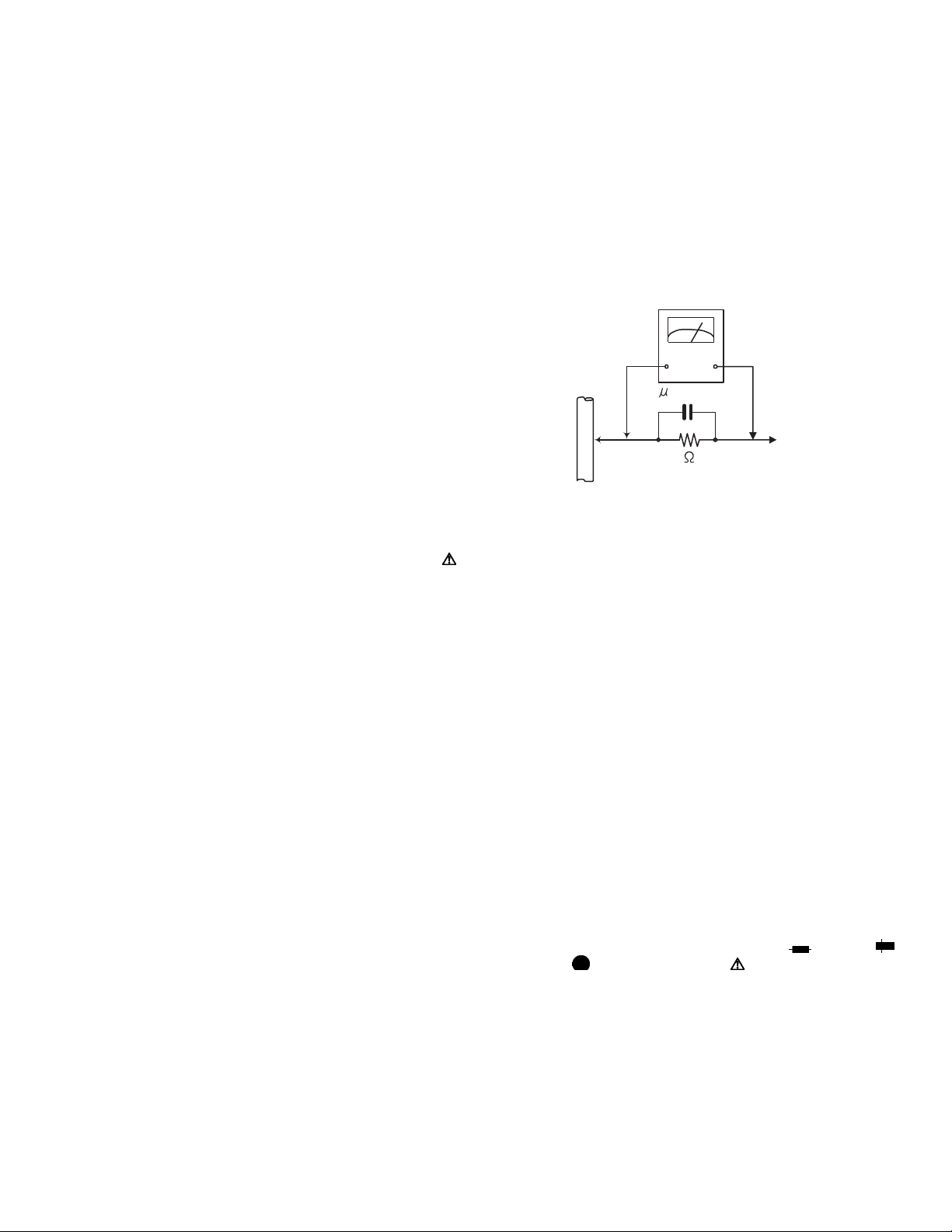
• Alternate check method
Plug the AC line cord directly into the AC outlet. Use an
AC voltmeter having, 1,000Ω per volt or more sensitivity
in the following manner. Connect a 1,500Ω 10W resistor
paralleled by a 0.15µF AC-type capacitor between an ex-
posed metal part and a known good earth ground.
Measure the AC voltage across the resistor with the AC
voltmeter.
Move the resistor connection to each exposed metal
part, particularly any exposed metal part having a return
path to the chassis, and measure the AC voltage across
the resistor. Now, reverse the plug in the AC outlet and
repeat each measurement. Voltage measured any must
not exceed 0.75 V AC (r.m.s.). This corresponds to 0.5
mA AC (r.m.s.).
AC VOLTMETER
(Having 1000
ohms/volts,
or more sensitivity)
0.15 F AC TYPE
Place this
probe on
1500 10W
Good earth ground
1.2 Warning
(1) This equipment has been designed and manufactured to
meet international safety standards.
(2) It is the legal responsibility of the repairer to ensure that
these safety standards are maintained.
(3) Repairs must be made in accordance with the relevant
safety standards.
(4) It is essential that safety critical components are replaced
by approved parts.
(5) If mains voltage selector is provided, check setting for local
voltage.
1.3 Caution
Burrs formed during molding may be left over on some parts
of the chassis.
Therefore, pay attention to such burrs in the case of preforming repair of this system.
1.4 Critical parts for safety
In regard with component parts appearing on the silk-screen
printed side (parts side) of the PWB diagrams, the parts that are
printed over with black such as the resistor ( ), diode ( )
and ICP ( ) or identified by the " " mark nearby are critical
for safety. When replacing them, be sure to use the parts of the
same type and rating as specified by the manufacturer.
(This regulation dose not Except the J and C version)
each exposed
metal part.
(No.MB387)1-3
Page 4
1.5 Safety Precautions (U.K only)
(1) This design of this product contains special hardware and many circuits and components specially for safety purposes. For con-
tinued protection, no changes should be made to the original design unless authorized in writing by the manufacturer. Replacement parts must be identical to those used in the original circuits.
(2) Any unauthorised design alterations or additions will void the manufacturer's guarantee; furthermore the manufacturer cannot
accept responsibility for personal injury or property damage resulting therefrom.
(3) Essential safety critical components are identified by ( ) on the Parts List and by shading on the schematics, and must never
be replaced by parts other than those listed in the manual. Please note however that many electrical and mechanical parts in
the product have special safety related characteristics. These characteristics are often not evident from visual inspection. Parts
other than specified by the manufacturer may not have the same safety characteristics as the recommended replacement parts
shown in the Parts List of the Service Manual and may create shock, fire, or other hazards.
(4) The leads in the products are routed and dressed with ties, clamps, tubings, barriers and the like to be separated from live parts,
high temperature parts, moving parts and/or sharp edges for the prevention of electric shock and fire hazard. When service is
required, the original lead routing and dress should be observed, and it should be confirmed that they have been returned to
normal, after re-assembling.
1.5.1 Warning
(1) Service should be performed by qualified personnel only.
(2) This equipment has been designed and manufactured to meet international safety standards.
(3) It is the legal responsibility of the repairer to ensure that these safety standards are maintained.
(4) Repairs must be made in accordance with the relevant safety standards.
(5) It is essential that safety critical components are replaced by approved parts.
(6) If mains voltage selector is provided, check setting for local voltage.
Burrs formed during molding may be left over on some parts of the chassis. Therefore,
pay attention to such burrs in the case of preforming repair of this system.
1-4 (No.MB387)
Page 5

SECTION 2
SPECIFIC SERVICE INSTRUCTIONS
This service manual does not describe SPECIFIC SERVICE INSTRUCTIONS.
(No.MB387)1-5
Page 6
SECTION 3
DISASSEMBLY
3.1 Main body section
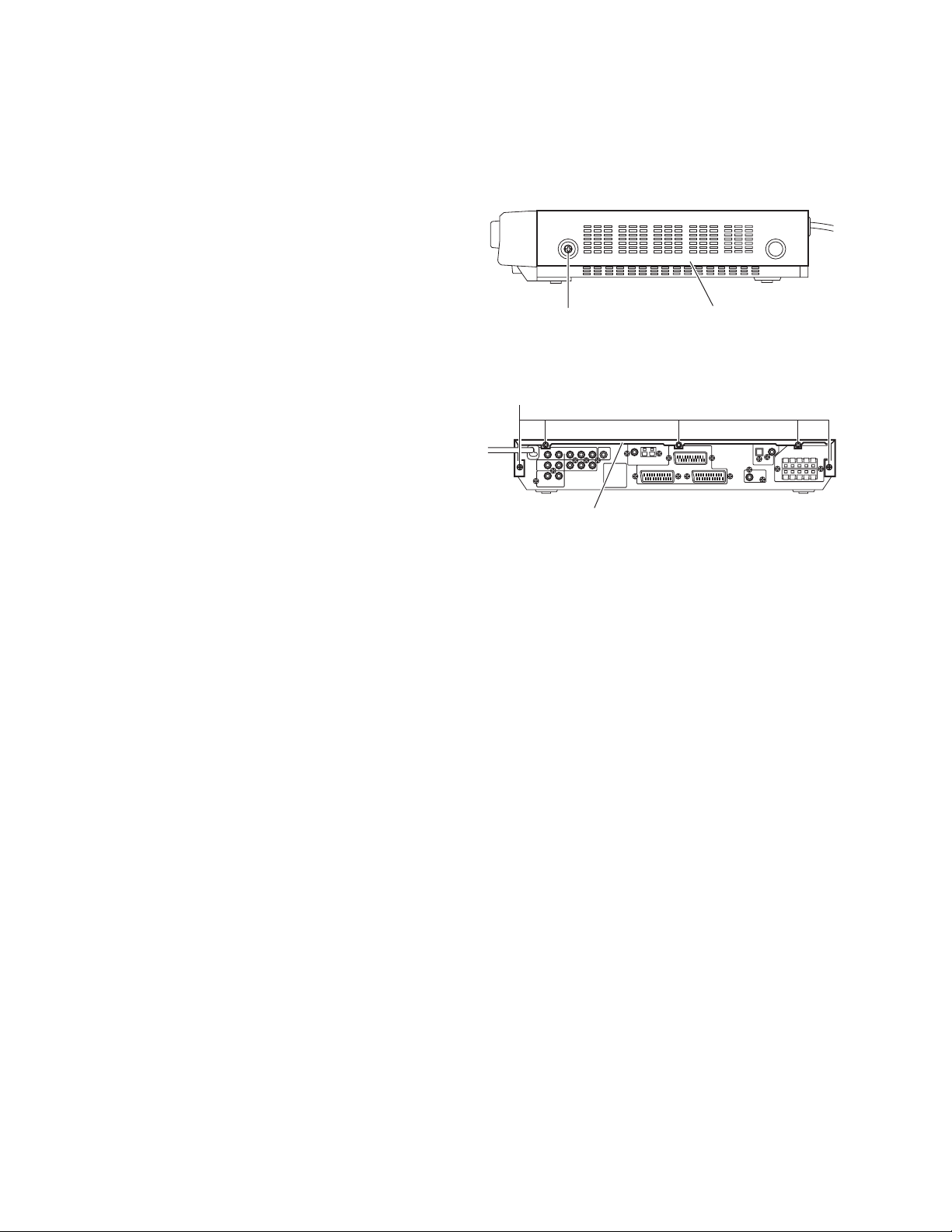
3.1.1 Removing the top cover
(See Figs. 1 and 2)
(1) From the both sides of the main body, remove the two
screws A attaching the top cover. (See Fig.1)
(2) From the back side of the main body, remove the five
screws B attaching the top cover. (See Fig.2)
B
A
Top cover
Top cover
Fig.1
Fig.2
1-6 (No.MB387)
Page 7
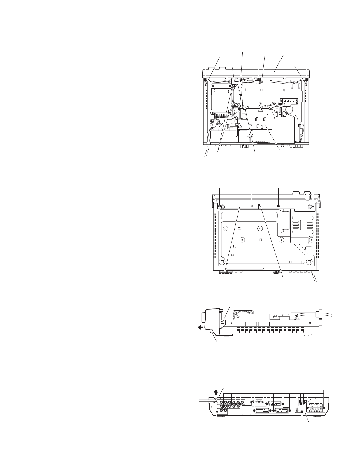
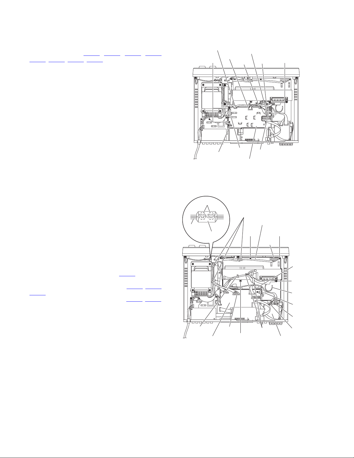
3.1.2 Removing the front panel assembly
(See Figs. 3 to 5)
• Rremove the top cover.
(1) From the top side of the main body, disconnect the wire
from the connector CN412
Fig.3)
Reference:
After reassembling, fix the wires with the wire holders as
before. (See Fig.3.)
(2) Disconnect the wire from the connector CN421
nection 2 board. (See Fig.3)
(3) Remove the two screws C and screw C' attaching the front
panel assembly. (See Fig.3)
Reference:
• When attaching the screw C, attach the earth wires
with them. (See Fig.3.)
• When attaching the screw C', attach a wire holder with
it. (See Fig.3.)
(4) From the bottom side of the main body, remove the four
screws D attaching the front panel assembly and release
the joint a. (See Fig.4)
(5) From the both sides of the main body, release the joints b
and take out the front panel assembly in the direction of the
arrow. (See Fig.5)
on the regulator board. (See
on the con-
Connection 2 board
Earth wire
CN421
Wire holders
Wire holder
CN412
Fig.3
Front panel assembly
Earth wire
Regulator board
CC'C
D
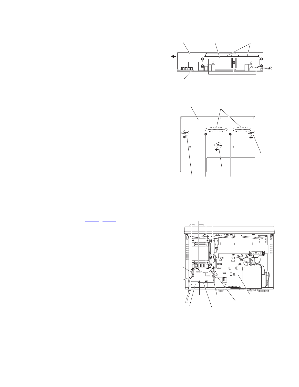
3.1.3 Removing the rear panel
(See Fig. 6)
• Remove the top cover.
(1) From the back side of the main body, remove strain relief
from the rear panel in the direction of the arrow.
(2) Remove the nineteen screws E attaching the rear panel.
Front panel assembly
b
Front panel assembly
Rear panel
E
a
Fig.4
Fig.5
E
Rear panel
Fig.6
(No.MB387)1-7
Page 8
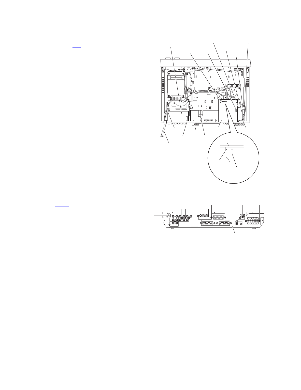
3.1.4 Removing the tuner
(See Figs. 7 and 8)
• Remove the top cover.
(1) From the top side of the main body, disconnect the card
wire from the connector CN1 on the tuner. (See Fig.7)
(2) From the back side of the main body, remove the two
screws F attaching the tuner to the rear panel. (See Fig.8)
3.1.5 Removing the PAL prg board
(See Figs. 7 and 8)
• Remove the top cover.
(1) From the back side of the main body, remove the four
screws G attaching the PAL prg board to the rear panel.
(See Fig.8)
(2) From the top side of the main body, remove the tie band fix-
ing the power cord. (See fig.7.)
Reference:
After reassembling, fix the power cord with a new tie
band as before. (See Fig.7.)
(3) Take out the PAL prg board and disconnect the card wire
from the connector CN751
prg board. (See Fig.7)
3.1.6 Removing the DSP board
(See Figs. 7 and 8)
• Remove the top cover.
(1) From the back side of the main body, remove the two
screws H attaching the DSP board to the rear panel. (See
Fig.8)
(2) From the top side of the main body, disconnect the connec-
tor CN601
(See Fig.7)
(3) Take out the DSP board and disconnect the card wire from
the connector CN602
board. (See Fig.7)
on the DSP board from the connection 1 board.
on the forward side of the PAL
on the forward side of the DSP
PAL prg board
CN601 CN602
Tie band
CN751
Power cord
SPK term. board
Tuner
DSP board
CN1
Fig.7
CN725
S.S.S. board
CN728
Tie band
DSP board
CN601
Connection 1
board
JHKFG
3.1.7 Removing the S.S.S. board
(See Fig 7)
• Remove the top cover.
(1) From the top side of the main body, remove the tie band
and disconnect the wire from the connector CN725
S.S.S. board.
Reference:
After attaching the S.S.S. board, fix the wire with a new
tie band as before.
(2) Disconnect the connector CN728
the SPK term. board.
(3) Take out the S.S.S. board.
on the S.S.S. board from
on the
Rear panel
Fig.8
1-8 (No.MB387)
Page 9
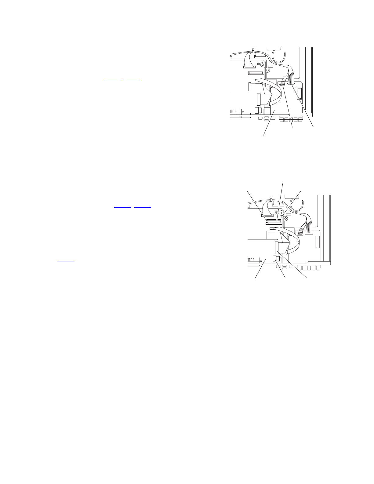
3.1.8 Removing the SPK term. board
(See Figs. 8 and 9)
• Remove the top cover, DSP board and S.S.S. board.
(1) From the back side of the main body, remove the two
screws J attaching the SPK term. board to the rear panel.
(See Fig.8)
(2) From the top side of the main body, disconnect the wires
from the connectors (CN301
board. (See Fig.9)
(3) Take out the SPK term. board.
3.1.9 Removing the SCART board
(See Figs. 8 and 10)
• Remove the top cover and DSP board.
(1) From the back side of the main body, remove the two
screws K attaching the SCART board to the rear panel.
(See Fig.8)
(2) From the top side of the main body, disconnect the card
wires from the connectors (CN513
board. (See Fig.10)
(3) Take out the SCART board.
, CN801) on the SPK term.
, CN514) on the SCART
SPK term. board
Connection 1 board
CN301 CN801
Fig.9
CN571
Input M board
3.1.10 Removing the connection 1 board
(See Fig. 10)
• Remove the top cover and DSP board.
(1) From the top side of the main body, disconnect the connec-
tor CN571
board.
(2) Take out the connection 1 board.
on the connection 1 board from the input M
SCART board CN513
Fig.10
CN514
(No.MB387)1-9
Page 10
3.1.11 Removing the regulator board
(See Fig. 11)
• Remove the top cover, tuner and DSP board.
(1) From the top side of the main body, disconnect the wires
from the connectors (CN201, CN207, CN208, CN261,
, CN510, CN520, CN721) on the regulator board.
CN412
(2) Remove the four screws L attaching the regulator board.
(3) Take out the regulator board.
CN412
CN261
LL
CN520
CN721
CN207
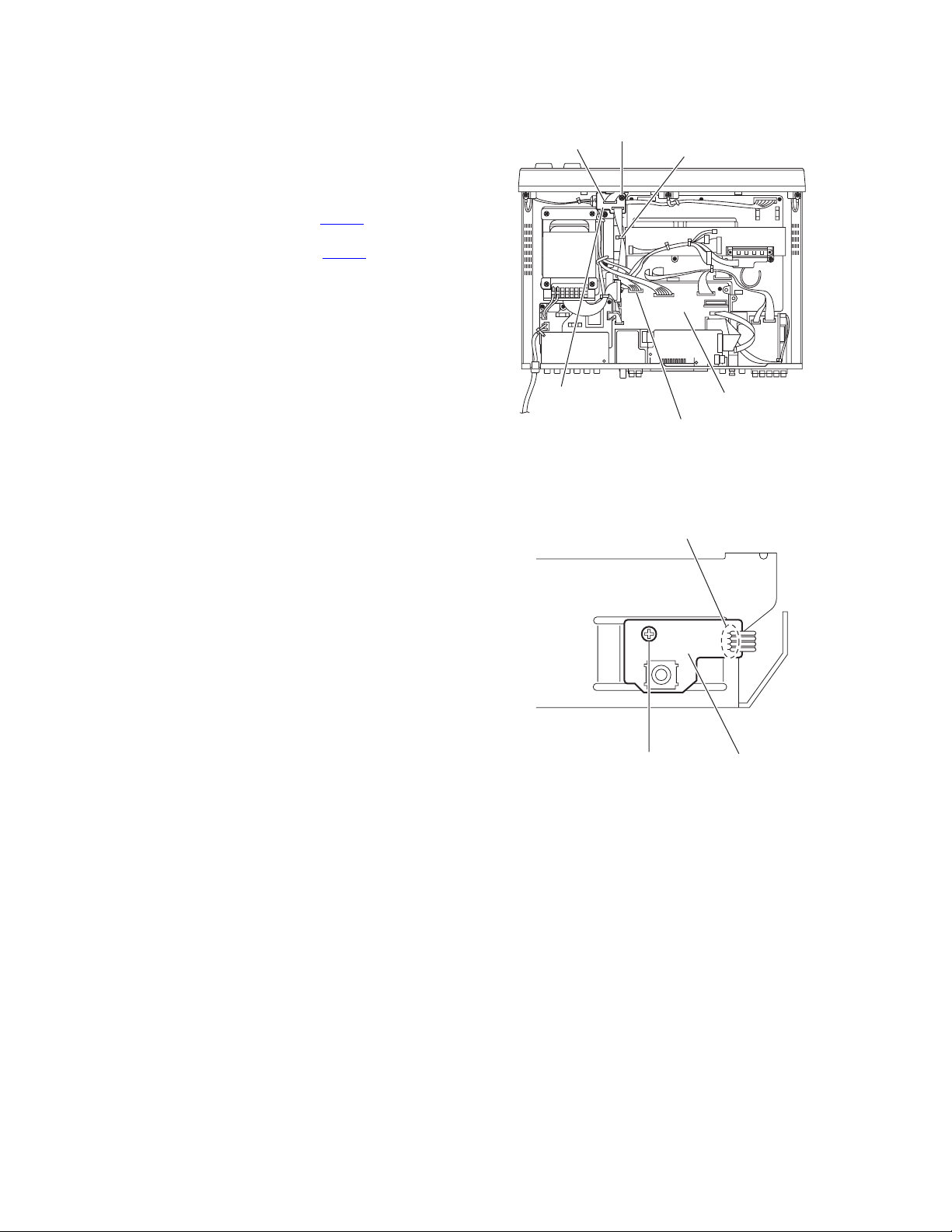
3.1.12 Removing the amp. board
(See Fig. 12)
• Remove the top cover, tuner, DSP board and regulator board.
(1) From the top side of the main body, remove the tie bands
bundling the wires.
Reference:
After reassembling, bundle the wires with the new tie
bands as before.
(2) Release the wire holders fixing the wires.
Reference:
After reassembling, fix the wires with the wire holders as
before.
(3) Release the claws c to open a noise filter and remove the
wires from the noise filter.
(4) Disconnect the wire from the connector CN506
M board.
(5) Disconnect the wires from the connectors (CN206
) on the amp. board.
CN701
(6) Disconnect the wires from the connectors (CN301
on the SPK term. board.
(7) Remove the two screws M, screw N and screw N' attaching
the amp. board
Reference:
When attaching the screw N', attach the earth wire with
it.
(8) Take out the amp. board.
on the input
, CN519,
, CN801)
Wires
Noise filter
Tie band
Input M board
CN208
c
CN201
Regulator board
Wire holders
CN506
N
Fig.11
Amp. board
Fig.12
CN510
CN701
Tie bands
MM
CN519
N'
Earth
wire
CN206
CN801
CN301
SPK term. board
1-10 (No.MB387)
Page 11
3.1.13 Removing the heat sink
(See Figs. 13 and 14)
• Remove the top cover, tuner, DSP board, regulator board and
amp. board.
(1) From the front side of the amp. board, remove the five
screws P attaching the IC bracket and take out the IC
bracket. (See Fig.13)
(2) From the bottom side of the amp. board, remove the two
screws Q attaching the heat sink. (See Fig.14)
(3) Move the heat sink in the direction of the arrow to release
the three claws d and remove the heat sink. (See Figs.13
and 14)
Heat sink
Amp. board
IC bracket
Power IC
P
3.1.14 Removing the power IC
(See Fig. 14)
• Remove the top cover, tuner, DSP board, regulator board and
amp. board and heat sink.
(1) From the bottom side of the amp. board, remove the sol-
ders from the soldered points e.
(2) Take out the power IC from the forward side of the amp.
board.
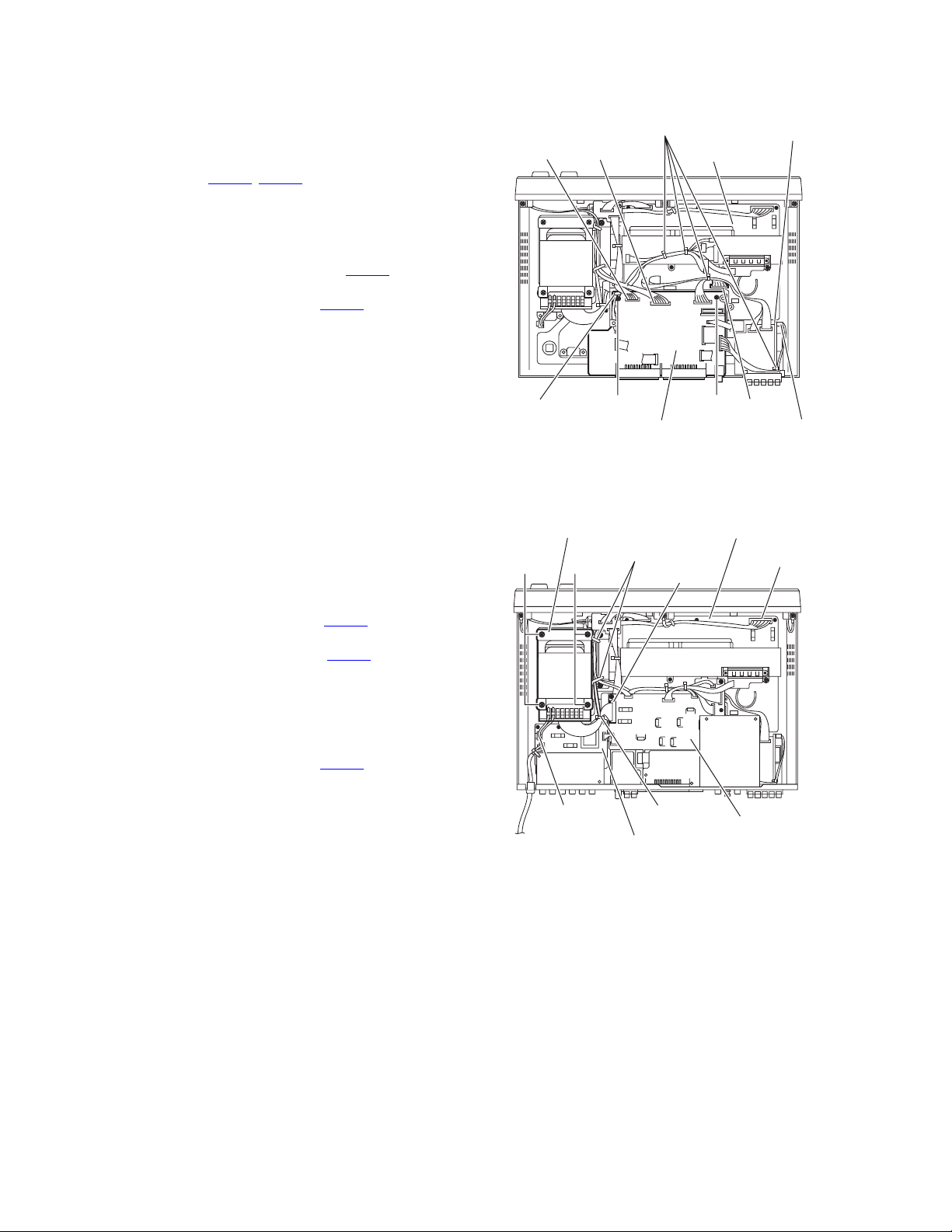
3.1.15 Removing the primary board
(See Fig. 15)
• Remove the top cover and PAL prg board.
(1) From the top side of the main body, disconnect the wires
from the connectors (CN202
board.
(2) Disconnect the wire from the connector CN208
ulator board.
(3) Remove the tie band bundling the wires.
Reference:
After reassembly, bundle the wires with the new tie band
as before.
(4) Remove the four screws R and screw R' attaching the pri-
mary board.
Reference:
When attaching the screw R', attach the barrier with it as
before.
(5) Take out the primary board.
, CN203) on the primary
on the reg-
CN202
CN203
Amp. board
d
R
R'
Barrier
Fig.13
e
d
Fig.14
Tie band
Primary board
d
QQ
Regulator board
CN208
Fig.15
(No.MB387)1-11
Page 12
3.1.16 Removing the input M board
(See Fig. 16)
• Remove the top cover, rear panel, tuner, PAL prg board, DSP
board, SCART board, Connection 1 board, regulator board
and primary board.
(1) From the top side of the main body, disconnect the wires
from the connectors (CN451
(2) Remove the tie bands fixing the wires.
Reference:
After reassembling, fix the wires with the new tie bands
as before.
(3) Disconnect the wire from the connector CN725
S.S.S. board.
(4) Disconnect the wire from the connector CN519
board.
(5) Remove the screw S and screw S' attaching the input M
board.
Reference:
When attaching the screw S', attach the wire holder with
it as before.
(6) Take out the input M board.
3.1.17 Removing the power transformer
(See Fig. 17)
• Remove the top cover.
(1) From the top side of the main body, remove the tie band
bundling the wire.
Reference:
After reassembling, fix the wires with the new tie band as
before.
(2) Disconnect the wire from the connector CN201
ulator board.
(3) Disconnect the wire from the connector CN202 on the pri-
mary board.
(4) Release the wire holders fixing the wires.
Reference:
When reassembling, fix the wires with the wire holders
as before.
(5) Disconnect the wire from the connector CN701
board.
(6) Remove the four screws T attaching the power transformer
and take out the power transformer.
, CN506) on the input M board.
on the
on the amp.
on the reg-
on the amp.
CN451 CN506
Wire holder
Power transformer
TT
CN202
Primary board
Tie bands
Input M board
Fig.16
Wire holders
CN201
Tie band
Amp. board
CN519
SS'
Amp. board
Regulator board
S.S.S board
CN725
CN701
1-12 (No.MB387)
Fig.17
Page 13
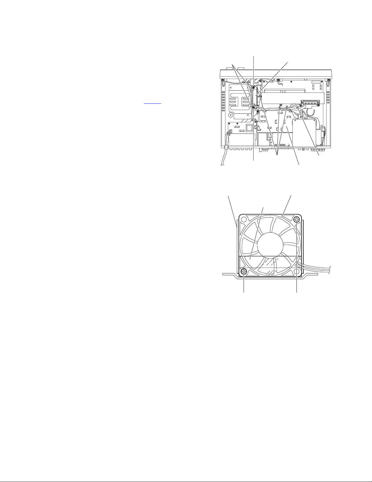
3.1.18 Removing the fan motor
(See Figs. 18 and 19)
• Remove the top cover.
Reference:
Remove the power transformer as required.
(1) From the top side of the main body, remove the tie bands
bundling the wires.
Reference:
After reassembling, bundle the wires with the new tie
bands as before.
(2) Disconnect the wire from the connector CN207
ulator board. (See Fig.18)
(3) Remove the two screw U attaching the fan assembly and
take out the fan assembly. (See Fig.18)
Reference:
After attaching the screws U, attach the wire holders with
them as before.
(4) Remove the screw V and screw V' attaching the fan motor
to the fan bracket. (See Fig.19)
Reference:
When attaching the screw V', attach the fan cover with it as before.
on the reg-
Wire holders
U
U
Fan assembly
Tie bands
Fig.18
CN207
Regulator board
Fan bracket
V'
Fan motor
Fan cover
V
Fig.19
(No.MB387)1-13
Page 14
3.1.19 Removing the connection 2 board
(See Fig. 20)
• Remove the top cover, tuner, DSP board and regulator board.
(1) From the top side of the main body, remove the tie band fix-
ing the wire.
Reference:
After reassembling, fix the wire with a new tie band as
before.
(2) Disconnect the wire from the connector CN451
M board.
(3) Disconnect the wire from the connector CN421
nection 2 board.
(4) Remove the screw W attaching the connection 2 board and
take out the connection 2 board.
on the input
on the con-
CN421
W
Tie band
3.1.20 Removing the H.P board
(See Fig. 21)
• Remove the top cover and front panel assembly.
(1) From the front side of the main body, remove the screw X
attaching the H.P board.
(2) Remove the solders from the soldered point f on the H.P
board.
Reference:
Remove the solders from the soldered point f as required.
Connection 2 board
Fig.20
X
Fig.21
Input M board
CN451
f
H.P board
1-14 (No.MB387)
Page 15

3.2 Front panel assembly section
3.2.1 Removing the JOG board
(See Figs. 22 and 23)
• Remove the top cover and front panel assembly.
(1) From the inside of the front panel assembly, remove the
four screws Y attaching the JOG board. (See Fig.22.)
(2) Take out the Jog board while lifting the JOG board from the
front panel assembly little by little. (See Fig.22.)
Reference:
The volume knob and MULTI JOG knob are removed
from the front side simultaneously. (See Fig.23.)
(3) From the forward side of the JOG board, disconnect the
wire from the connector CN413
3.2.2 Removing the FL board
(See Fig. 22)
• Remove the top cover and front panel assembly.
(1) From the inside of the front panel assembly, disconnect the
wire from the connector CN413
Fig.22.)
Reference:
Remove the JOG board as required.
(2) Remove the four screws Z attaching the FL board and take
out the FL board.
(3) From the forward side of the FL board, disconnect the wires
from the connectors (CN414
. (See Fig.22)
on the JOG board. (See
, CN415).
Y
JOG board FL board
Front panel assembly
CN413
Z
Fig.22
Front panel assembly
MULTI JOG knob
Fig.23
Z
CN415 CN414
Volume knob
3.2.3 Removing the key board
(See Fig. 24)
• Remove the top cover, front panel assembly and FL board.
(1) From the inside of the front panel assembly, remove the
seven screws AA attaching the key board.
(2) Take out the key board.
Front panel assembly
AA
Fig.24
Key board
AA
AA
(No.MB387)1-15
Page 16

SECTION 4
ADJUSTMENT
This service manual does not describe ADJUSTMENT.
1-16 (No.MB387)
Page 17

SECTION 5
TROUBLESHOOTING
This service manual does not describe TROUBLESHOOTING.
(No.MB387)1-17
Page 18

Victor Company of Japan, Limited
AV & MULTIMEDIA COMPANY AUDIO/VIDEO SYSTEMS CATEGORY 10-1,1chome,Ohwatari-machi,Maebashi-city,371-8543,Japan
(No.MB387)
Printed in Japan
VPT
Page 19

PARTS LIST
[ RX-E11S ] [ RX-E12B ]
* All printed circuit boards and its assemblies are not available as service parts.
Area suffix
B ------------------------------- U.K.
E ----------- Continental Europe
EN ------------ Northern Europe
EV -------------- Eastern Europe
MB387
- Contents -
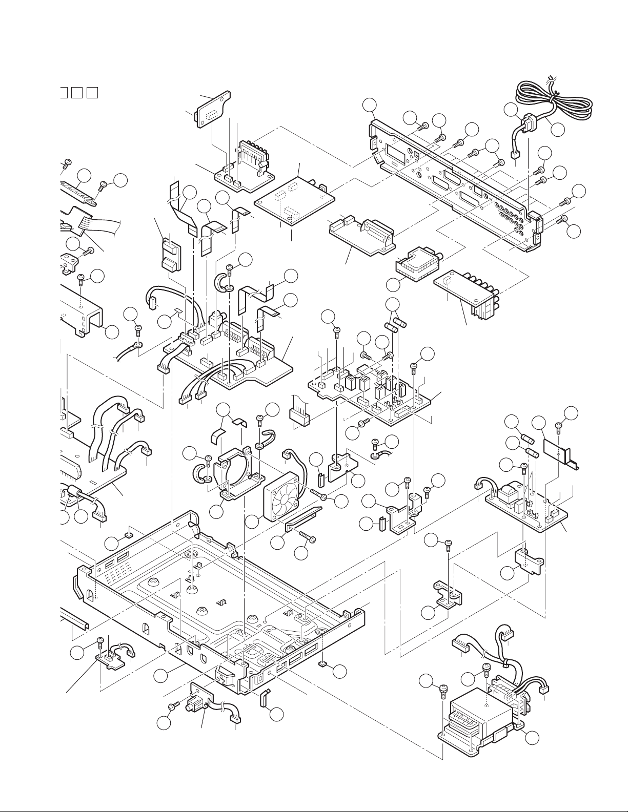
Exploded view of general assembly and parts list (Block No.M1)
Electrical parts list (Block No.01~03)
Packing materials and accessories parts list (Block No.M3)
3- 2
3- 6
3-16
3-1
Page 20
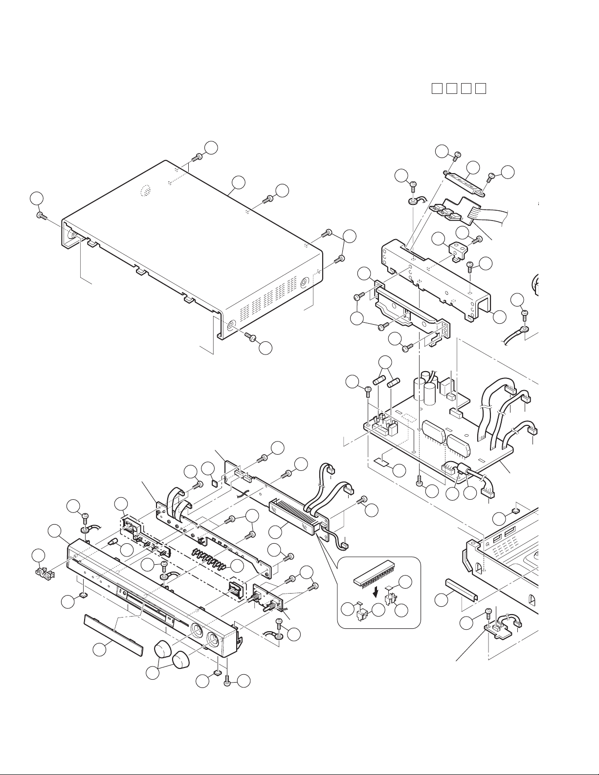
Exploded view of general assembly and parts list
a
d
d
Block No.
M
M
1
M
65
64
63
37
64
34
33
Connection 1 bo
34
aa
64
29
A
B
A
65
32
32
70
36
23
24
Transistor boar
37
38
30
j
q
p
a
FL board
84
Key board
12
1
7
8
9
9
28
y
31
n
8
71
9
bb
62
A
61
k
16
g
Amp. boar
3-2
bb
8
10
JOG board
12
75
73
74
72
15
35
Connection 2 board
n
m
2
3
5
12
4
66
3
6
11
Page 21
M
j
M
33
24
37
34
Connection 1 board
aa
Transistor board
38
30
S.S.S. board
o
SPK term. board
t
83
82
z
o
85
p
q
DSP board
81
w
v
t
w
v
z
38
r
79
80
s
Input M board
k
m
SCART board
40
f
d
50
52
57
51
54
60
59
56
x
53
58
B
51
s
55
68
78
e
76
g
r
PAL prg board
40
D
h
aa
e
f
q
p
47
44
g
Amp. board
61
2
42
43
47
y
77
26
27
d
25
46
19
17
18
k
16
45
46
Regulator board
b
39
22
39
x
c
39
69
67
21
h
Primary
board
35
tion 2 board
20
D
20
n
b
c
48
3-3
m
C
13
41
H.P board
a
16
49
49
A
14
j
Page 22

General Assembly
Block No. [M][1][M][M]
Symbol No. Part No. Part Name Description Local
1 LV11 04 3- 00 4A FRONT PANEL E11SB,E11SE,E11SEN,E11SEV
1 LV11043-006A FRONT PANEL E12BB,E12BE,E12BEN,E12B EV
2 LV4 3338-002A JVC MARK
3 LV4 3622-002A FOOT (x2)
4 LV3 5692-001A LENS
5 LV4 4135-001A INDICATOR(POWER
6 LV3 5693-001A INDICATOR( S OURC
7 LV21903-001A PUSH BUTTON E11SB,E11SE,E11SEN,E11SEV
7 LV21903-002A PUSH BUTTON E12BB,E12BE,E12BEN,E12BEV
8 QYSBSF2608ZA TAP SCREW M2.6 x 8mm(x7)
9 QYSBSF2608ZA TAP SCREW M2.6 x 8mm(x4)
10 QYSBSF2608ZA TA P SC REW M2.6 x 8mm(x4)
11 QYSDSG3006ZA TAP SCREW M3 x 6mm(x4)
12 QYSBSG3006ZA TAP SCREW M3 x 6mm(x3)
13 LV10868-003A CHASSIS BASE
14 LV30225-0F4A SPACER
15 LV30225-0T1A SPACER
16 LV43622-002A FOOT (x2)
17 LV34681-002A SUPPORT BRACKET
18 LV30225-0F4A SPACER
19 QYSBST3005EA TAP SCREW M3 x 5mm
20 LV34679-001A PWB BRACKET (x2)
21 LV35264-001A BARRIER
22 QYSBST3005EA TAP SCREW M3 x 5mm(x2)
23 LV34682-001A C.B BRACKET
24 QYSBSG3006ZA TAP SCREW M3 x 6mm
25 LV34784-001A SUPPORT BKT(B)
26 LV30225-0F4A SPACER
27 QYSBST3005EA TAP SCREW M3 x 5mm
28 LV30225-0H3A SPACER
29 LV34688-001A I.C BRACKET
30 LV21638-002A HEAT SINK
31 QYSBSG3006ZA TAP SCREW M3 x 6mm(x2)
32 QYSBSG3006ZA TAP SCREW M3 x 6mm(x5)
33 LV35043-002A TRANSISTOR HOLD
34 QYSBSG3006ZA TAP SCREW M3 x 6mm(x2)
35 QYSBSG3006ZA TAP SCREW M3 x 6mm
36 QYSBSG3006ZA TAP SCREW M3 x 6mm(x2)
37 QYSBSG3008EA TAP SCREW M3 x 8mm(x2)
38 QYSBSG3006ZA TAP SCREW M3 x 6mm(x2)
39 QYSBSG3006ZA TAP SCREW M3 x 6mm(x5)
40 QYSBSG3006ZA TAP SCREW M3 x 6mm(x4)
41 QYSBSG3006ZA TAP SCREW M3 x 6mm
42 LV34676-002A FAN BRACKET
43 QAR0312-002 FAN MOTE R
44 LV30225-0Y9A SP ACER (x2)
45 LV35129-001A FAN COVER
46 QYSBSG3020ZA TAP SCREW M3 x 20mm(x2)
47 QYSBST3005EA TAP SCREW M3 x 5mm(x2)
48 QQT0444-001 POWER TRANSF
49 QYSDSTL4006EA TAP SCREW M4 x 6mm(x4)
50 LV21639-036A REAR PANEL E11SB,E1 1SE,E11SEN
50 LV21639-037A REAR PANEL E11SEV
50 LV21639-043A REAR PANEL E12BB,E12BE,E12BEN,E12BEV
51 QYSBSGY3008EA TAP SCREW M3 x 8mm(x2)
52 QYSBSGY3008EA TAP SCREW M3 x 8mm(x2)
53 QYSBSGY3008EA TAP SCREW M3 x 8mm(x5)
54 QYSBSGY3008EA TAP SCREW M3 x 8mm(x2)
55 QAU0278-003 TUNER
56 QYSBSGY3008EA TAP SCREW M3 x 8mm(x2)
57 QYSBSGY3008EA TAP SCREW M3 x 8mm(x2)
58 QYSBSGY3008EA TAP SCREW M3 x 8mm(x4)
59 QMPN160-200-JD POWER CORD(EK) 2m BLACK E11SB,E12BB
59 QMPK210-205-JN POWER CORD(EK) 2.05m BLACK
60 QZW0033-001 STRAIN RELIEF
61 QQR0491-001 NOISE FILTER T DK (GRAY)
62 VYSH101-009 SPACER
63 LV21640-002A TOP COVER E1 1SB,E11SE,E11SEN,E11SEV
63 LV21640-003A TOP COVER E12BB,E12BE,E12BEN,E12BEV
64 QYSBSGY3008EA TAP SCREW M3 x 8mm(x5)
65 QYSDSG3008NA TAP SCREW M3 x 8mm(x2) E11SB,E11SE,E11SEN,E11SEV
65 QYSDSG3008MA TAP SCREW M3 x 8mm(x2) E12BB,E12BE,E12BEN,E12BEV
66 LV43684-002A JOG KNOB A SSY (x2) E11SB,E11SE,E11SEN,E11SEV
E11SE,E11SEN,E11SEV,E12BE,
E12BEN,E12BEV
3-4
Page 23

Symbol No. Part No. Part Name Des cr i pt ion Local
66 LV43684-003A JOG KNOB ASSY (x2) E12BB,E12BE,E12BEN,E12BEV
67 QMF 51W2-1R0-J8 FUSE 1A AC250V
68 QMF 51W2-2R0-J8 FUSE 2A AC250V
69 QMF 5AE2-R10-J1 FUSE 0.1A AC250V
70 QMF 51W2-4R0-J8 FUSE 4A AC250V
71 QLF0 135-001 FL TUBE
72 LV34673-001A FL HO LDER(L)
73 LV34687-001A FL HO LDER(R)
74 VYSH101-009 SPACER
75 LV30225-0S4A SPACER
76 QYSBSG3008EA TAP SCREW M3 x 8mm
77 QYSBSG3008EA TAP SCREW M3 x 8mm
78 QYSBSG3008EA TAP SCREW M3 x 8mm (x4)
79 QUQ412-1212CJ FFC WIRE 12pin 12cm
80 QUQ412-1111CJ FFC WIRE 11pin 11cm
81 QUQ412-0914CJ FFC WIRE 9pin 14cm
82 QUQ412-2214CJ FFC WIRE 22pin 14cm
83 QUQ412-1115CJ FFC WIRE 11pin 15cm
84 VYSH101-009 SPACER
85 LV30225-0F4A SPACER
3-5
Page 24

Electrical parts list
Main board
Block No. [0] [1 ]
Symbol No.
IC401 MN101C35DMF IC
IC402 GP1UM271XKV F IR DETECT UNIT
Q201 KRC105S-X DIGI TRANSISTOR
Q203 KTC3203/OY/-T TRANSISTOR
Q204 KTC3200/GL/-T TRANSISTOR
Q205 KTA1046/Y/ TRANSISTOR *
Q207 KTA1046/Y/ TRANSISTOR *
Q208 2SD2394/EF/ TRANSISTOR
Q209 2SD2394/EF/ TRANSISTOR
Q210 2SD2394/EF/ TRANSISTOR
Q211 2SD2394/EF/ TRANSISTOR
Q212 2SD2394/EF/ TRANSISTOR
Q213 2SD2394/EF/ TRANSISTOR
Q214 KRA102S-X DIGI TRANSISTOR
Q215 KRC102S-X DIGI TRANSISTOR
Q216 KRA102S-X DIGI TRANSISTOR
Q217 KRC102S-X DIGI TRANSISTOR
Q218 KRA102S-X DIGI TRANSISTOR
Q219 KRC102S-X DIGI TRANSISTOR
Q220 KRC111S-X TRANSISTOR
Q221 KRC111S-X TRANSISTOR
Q222 KRC111S-X TRANSISTOR
Q223 KRC111S-X TRANSISTOR
Q224 KRC111S-X TRANSISTOR
Q226 2SD2394/EF/ TRANSISTOR
Q231 KRC102S-X DIGI TRANSISTOR
Q404 KRA107S- X TRANSISTOR
Q405 KRA107S- X TRANSISTOR
Q406 KRA107S- X TRANSISTOR
Q407 KRA107S- X TRANSISTOR
Q408 KRA107S- X TRANSISTOR
Q409 KRA107S- X TRANSISTOR
Q410 KRC107S-X DIGI TRANSISTOR
D201 1A3G-T1 DIODE
D202 1A3G-T1 DIODE
D203 1A3G-T1 DIODE
D204 1A3G-T1 DIODE
D205 MA111-X DIODE C.M
D207 MTZJ6.2C-T2 Z DIODE
D208 1A3G-T1 DIODE
D209 1A3G-T1 DIODE
D210 1A3G-T1 DIODE
D211 1A3G-T1 DIODE
D212 1A3G-T1 DIODE
D213 1A3G-T1 DIODE
D215 MTZJ7.5C-T2 Z DIODE
D216 MTZJ7.5C-T2 Z DIODE
D217 MTZJ6.2C-T2 Z DIODE
D218 MTZJ10B-T2 Z DIODE
D219 MTZJ5.6C-T2 Z DIODE
D220 MTZJ5.6C-T2 Z DIODE
D221 MA111-X DIODE C.M
D222 1A3G-T1 DIODE
D223 MTZJ22 C- T2 Z DIODE
D224 MTZJ6.2C-T2 Z DIODE
D227 MTZJ7.5C-T2 Z DIODE
D231 1A3G-T1 DIODE
D233 1A3G-T1 DIODE
D234 1A3G-T1 DIODE
D401 SLR-343VC-T LED
D402 SLR-343VC-T LED
D403 SLR-343VC-T LED
D404 SPR-325MVW /L/-T LED GREEN-RED
D405 SPR-325MVW /L/-T LED GREEN-RED
D406 SPR-325MVW /L/-T LED GREEN-RED
D410 MA111-X DIODE C.M
D411 SLR-343VC-T LED
C201 QCZ9104-472 C CAPACITOR 4700pF
C202 QFLC2AJ-4 72Z M CAPACITOR 4700pF 100V J
Part No. Part Name Description Local
Symbol No.
C203 QETN1EM-227Z E CAPACITOR 220uF 25V M
C205 NCB3 1H K-472X C CAPACITOR 4700pF 50V K
C206 QETN1CM-477Z E CAPACITOR 470uF 16V M
C207 QFLC2AJ-104Z M CAPACITOR 0.1uF 100V J
C208 QFLC2AJ-104Z M CAPACITOR 0.1uF 100V J
C209 QFLC2AJ-104Z M CAPACITOR 0.1uF 100V J
C210 QETM1EM-338 E CAPACITOR 3300uF 25V M
C211 QETM1EM-108 E CAPACITOR 1000uF 25V M
C212 QFLC1HJ-473Z M CAPACITOR 0.047uF 50V J
C213 QFLC1HJ-473Z M CAPACITOR 0.047uF 50V J
C214 QEKC1HM-105Z E CAPACITOR 1uF 50V M
C215 QETN1HM-476Z E CAPACITOR 47uF 50V M
C221 QETN1CM-107Z E CAPACITOR 100uF 16V M
C222 QETN1CM-107Z E CAPACITOR 100uF 16V M
C223 QETN1CM-107Z E CAPACITOR 100uF 16V M
C224 QETM1EM-108 E CAPACITOR 1000uF 25V M
C225 QETN1CM-107Z E CAPACITOR 100uF 16V M
C226 QETN1CM-107Z E CAPACITOR 100uF 16V M
C227 QETN1CM-107Z E CAPACITOR 100uF 16V M
C231 QETN1CM-107Z E CAPACITOR 100uF 16V M
C241 QETN1HM-227Z E CAPACITOR 220uF 50V M
C242 QETN2AM-107Z E CAPACITOR 100uF 100V M
C243 QETN2AM-107Z E CAPACITOR 100uF 100V M
C251 QEKC1CM-226Z E CAPACITOR 22uF 16V M
C401 NCB31HK-103X C CAPACITOR 0.01uF 50V K
C402 NCB31HK-103X C CAPACITOR 0.01uF 50V K
C403 NCB31HK-103X C CAPACITOR 0.01uF 50V K
C404 NCB31HK-103X C CAPACITOR 0.01uF 50V K
C405 NCB31HK-103X C CAPACITOR 0.01uF 50V K
C406 QCZ0202-155Z C CAPACITOR 1.5uF 25V Z
C407 QEKC0JM-107Z E CAPACITOR 100uF 6.3V M
C408 QEKC0JM-107Z E CAPACITOR 100uF 6.3V M
C409 QEKC1HM- 475Z E CAPACITOR 4.7uF 50V M
C410 QER61HM-475Z E CAPACITOR 4.7uF 50V M
C411 QEKC1HM-475Z E CAPACIT OR 4.7uF 50V M
C412 NCF31CZ-104X C CAPACITOR 0.1uF 16V Z
C413 NCF31CZ-104X C CAPACITOR 0.1uF 16V Z
C414 NCF31CZ-104X C CAPACITOR 0.1uF 16V Z
C415 NCF31CZ-104X C CAPACITOR 0.1uF 16V Z
C418 NCF31CZ-104X C CAPACITOR 0.1uF 16V Z
C421 NCB3 1H K-102X C CAPACITOR 1000pF 50V K
C425 NDC 3 1H J-331X C CAPACITOR 330pF 50V J
C426 NDC 3 1H J-331X C CAPACITOR 330pF 50V J
C427 NDC 3 1H J-331X C CAPACITOR 330pF 50V J
C428 NDC 3 1H J-331X C CAPACITOR 330pF 50V J
C429 NCB31HK-103X C CAPACITOR 0.01uF 50V K
C431 NCF31CZ-104X C CAPACITOR 0.1uF 16V Z
C432 NCF31CZ-104X C CAPACITOR 0.1uF 16V Z
C433 NCF31CZ-104X C CAPACITOR 0.1uF 16V Z
C434 NCF31CZ-104X C CAPACITOR 0.1uF 16V Z
C435 NCB31HK-103X C CAPACITOR 0.01uF 50V K
C436 NCB31HK-103X C CAPACITOR 0.01uF 50V K
R202 QRJ146J-100X UNF C RESISTOR 10Ω 1/4W J
R203 QRJ146J-100X UNF C RESISTOR 10Ω 1/4W J
R206 QRJ146J-681X UNF C RESISTOR 680Ω 1/4W J
R207 QRJ146J-8R2X UNF C RESISTOR 8.2Ω 1/4W J
R208 NRSA63J-104X MG RESISTOR 100k
R209 QRJ146J-100X UNF C RESISTOR 10Ω 1/4W J
R210 QRZ9005-100X FUSI RESISTOR 10
R211 QRK1 26J-562X U N F C R ESISTOR 5.6kΩ 1/2W J
R215 QRZ9005-100X FUSI RESISTOR 10
R216 QRJ146J-152X UNF C RESISTOR 1.5kΩ 1/4W J
R217 QRZ9006-8R2X FUSI RES I STO R 8.2
R218 QRJ146J-152X UNF C RESISTOR 1.5kΩ 1/4W J
R219 NRSA63J-223X MG RESISTOR 22k
R220 NRSA63J-473X MG RESISTOR 47k
R221 QRZ9005-100X FUSI RESISTOR 10
R222 QRJ146J-332X UNF C RESISTOR 3.3kΩ 1/4W J
R223 NRSA63J-102X MG RESISTOR 1k
R224 NRSA63J-104X MG RESISTOR 100k
R225 QRZ9005-100X FUSI RESISTOR 10
R226 QRJ146J-102X UNF C RESISTOR 1kΩ 1/4W J
R227 NRSA63J-393X MG RESISTOR 39k
R228 NRSA63J-473X MG RESISTOR 47k
R229 QRZ9006-4R7X FUSI RES I STO R 4.7Ω 1/4W J
Part No. Part Name Description Local
Ω
Ω
Ω
Ω
Ω
1/16W J
Ω
1/16W J
Ω
Ω
1/16W J
Ω
Ω
Ω
1/16W J
Ω
1/16W J
1/16W J
1/16W J
3-6
Page 25

Symbol No.
R230 QRZ9006-4R7X FUSI RESI STO R 4.7Ω 1/4W J
R231 QRJ146J- 182X UNF C RES ISTOR 1.8kΩ 1/4W J
R232 QRJ146J- 2R 2X UNF C RESISTOR 2.2Ω 1/4W J
R233 QRJ146J- 2R 2X UNF C RESISTOR 2.2Ω 1/4W J
R234 NRSA63J-102X MG RES I STO R 1k
R235 NRSA63J-104X MG RES I STO R 100k
R236 QRZ9005-100X FUSI RESISTOR 10
R237 QRJ146J- 332X UNF C RES ISTOR 3.3kΩ 1/4W J
R238 NRSA63J-102X MG RES I STO R 1k
R239 NRSA63J-104X MG RES I STO R 100k
R242 NRSA63J-222X MG RES I STO R 2.2k
R245 QRJ146J- 2R 2X UNF C RESISTOR 2.2Ω 1/4W J
R247 QRZ9006-4R7X FUSI RESI STO R 4.7Ω 1/4W J
R248 QRJ146J- 152X UNF C RES ISTOR 1.5kΩ 1/4W J
R249 NRSA63J-511X MG RESI STO R 510
R250 NRSA63J-104X MG RES I STO R 100k
R252 QRJ146J- 2R 2X UNF C RESISTOR 2.2Ω 1/4W J
R253 QRJ146J- 2R 2X UNF C RESISTOR 2.2Ω 1/4W J
R254 QRJ146J- 100X UNF C RESISTOR 10Ω 1/4W J
R255 QRJ146J- 2R 2X UNF C RESISTOR 2.2Ω 1/4W J
R256 QRJ146J- 2R 2X UNF C RESISTOR 2.2Ω 1/4W J
R401 NRSA63J-103X MG RES I STO R 10k
R402 NRSA63J-102X MG RES I STO R 1k
R403 NRSA63J-102X MG RES I STO R 1k
R404 NRSA63J-103X MG RES I STO R 10k
R405 NRSA63J-102X MG RES I STO R 1k
R406 NRSA63J-102X MG RES I STO R 1k
R407 NRSA63J-122X MG RES I STO R 1.2k
R408 NRSA63J-103X MG RES I STO R 10k
R409 NRSA63J-102X MG RES I STO R 1k
R410 NRSA63J-102X MG RES I STO R 1k
R411 NRS A63J-103X MG RESISTO R 10k
R412 NRSA63J-102X MG RES I STO R 1k
R413 NRSA63J-102X MG RES I STO R 1k
R414 NRSA63J-122X MG RES I STO R 1.2k
R419 NRSA63J-103X MG RES I STO R 10k
R420 NRSA63J-102X MG RES I STO R 1k
R421 NRSA63J-102X MG RES I STO R 1k
R422 NRSA63J-122X MG RES I STO R 1.2k
R423 NRSA63J-152X MG RES I STO R 1.5k
R430 NRSA63J-221X MG RES I STO R 220
R431 NRSA63J-103X MG RES I STO R 10k
R432 NRSA63J-103X MG RES I STO R 10k
R433 NRSA63J-103X MG RES I STO R 10k
R434 NRSA63J-103X MG RES I STO R 10k
R435 NRSA63J-103X MG RES I STO R 10k
R436 NRSA63J-221X MG RES I STO R 220
R437 NRSA63J-221X MG RES I STO R 220
R438 NRSA63J-331X MG RES I STO R 330
R439 NRSA63J-221X MG RES I STO R 220
R440 NRSA63J-221X MG RES I STO R 220
R441 NRSA63J-221X MG RES I STO R 220
R442 NRSA63J-221X MG RES I STO R 220
R443 NRSA63J-221X MG RES I STO R 220
R444 NRSA63J-221X MG RES I STO R 220
R445 NRSA63J-104X MG RES I STO R 100k
R447 NRSA63J-103X MG RES I STO R 10k
R448 NRSA63J-103X MG RES I STO R 10k
R449 NRSA63J-103X MG RES I STO R 10k
R450 NRSA63J-103X MG RES I STO R 10k
R452 NRSA63J-221X MG RES I STO R 220
R453 NRSA63J-103X MG RES I STO R 10k
R454 NRSA63J-103X MG RES I STO R 10k
R455 NRSA63J-103X MG RES I STO R 10k
R456 NRSA63J-103X MG RES I STO R 10k
R457 NRSA63J-0R0X MG RESISTOR 0
R458 NRSA63J-0R0X MG RESISTOR 0
T202 Q QT0478-002 POWER TRANSF
CN201 QGA3901C1-09 CONNECTOR W-B (1-9)
CN202 QGA7901C1-02 CONNECTOR W-B (1-2)
CN203 QGA7901C1-02 CONNECTOR W-B (1-2)
CN207 QGA2501C1-02 CONNECTOR W-B (1-2)
CN208 QGA2501C1-04 CONNECTOR W-B (1-4)
CN218 QJK025-040604-E SIN CR C-B
CN261 QGA2001C1-07 CONNECTOR W-B (1-7)
CN403 QJK018-050800-E SIN CR C-B
Part No. Part Name Description Local
Ω
1/16W J
Ω
Ω
Ω
1/16W J
Ω
Ω
Ω
Ω
Ω
Ω
1/16W J
Ω
1/16W J
Ω
Ω
1/16W J
Ω
1/16W J
Ω
Ω
Ω
1/16W J
Ω
1/16W J
Ω
Ω
1/16W J
Ω
1/16W J
Ω
Ω
Ω
1/16W J
Ω
1/16W J
Ω
Ω
Ω
Ω
Ω
Ω
Ω
Ω
Ω
Ω
Ω
Ω
Ω
Ω
Ω
Ω
Ω
Ω
Ω
Ω
Ω
Ω
Ω
Ω
Ω
Ω
Ω
Ω
1/16W J
Ω
1/16W J
1/16W J
1/16W J
1/16W J
1/16W J
1/16W J
1/16W J
1/16W J
1/16W J
1/16W J
1/16W J
1/16W J
1/16W J
1/16W J
1/16W J
1/16W J
1/16W J
1/16W J
1/16W J
1/16W J
1/16W J
1/16W J
1/16W J
1/16W J
1/16W J
1/16W J
1/16W J
1/16W J
1/16W J
1/16W J
1/16W J
1/16W J
1/16W J
1/16W J
1/16W J
1/16W J
1/16W J
1/16W J
1/16W J
1/16W J
Symbol No.
CN412 QGA2001C1-05 CONNECTOR W-B (1-5)
CN413 QGA2001F1-05 CONNECTOR W-B (1-5)
CN414 QGA2001F1-09 CONNECTOR W-B (1-9)
CN415 QGA2001F1-08 CONNECTOR W-B (1-8)
CN421 QGA2001C1-09 CONNECTOR W-B (1-9)
CN431 QJK034-092204-E SIN CR C-B WIR
CN510 QGA2501C1-09 CONNECTOR W-B (1-9)
CN520 QGA2501C1-07 CONNECTOR W-B (1-7)
CN721 QGA2001C1-04 CONNECTOR W-B (1-4)
EP201 QNZ0136-001Z E ARTH PLATE
EP202 QNZ0136-001Z E ARTH PLATE
EP204 QNZ0136-001Z E ARTH PLATE
FC202 QNG0020-001Z FUSE CLIP I.M
FC203 QNG0020-001Z FUSE CLIP I.M
FC204 QNG0020-001Z FUSE CLIP I.M
FC205 QNG0020-001Z FUSE CLIP I.M
FC212 QNG0020-001Z FUSE CLIP I.M
FC213 QNG0020-001Z FUSE CLIP I.M
FC214 QNG0020-001Z FUSE CLIP I.M
FC215 QNG0020-001Z FUSE CLIP I.M
FW251 WJS0045-001A-E E-FL/RB WIRE
FW401 WJS0038-002A-E E-FL/RB WIRE
FW402 WJS0039-001A-E E-FL/RB WIRE
FW404 WJS0064-001A-E E-FL/RB WIRE
FW405 WJS0063-001A-E E-FL RB WIRE
HS205 E 70306-006 H EAT SINK
HS207 E 70306-006 H EAT SINK
HS208 E 70306-006 H EAT SINK
HS209 E 70306-006 H EAT SINK
HS213 E 70306-006 H EAT SINK
JS401 QSW1016-001 ROT ARY ENCODER
JS402 QSW1022-002 ROT ARY ENCODER
RY201 QSK0128-001 RELAY
S401 QSW0683- 001Z PUSH SW I.M
S402 QSW0683- 001Z PUSH SW I.M
S403 QSW0683- 001Z PUSH SW I.M
S404 QSW0683- 001Z PUSH SW I.M
S405 QSW0683- 001Z PUSH SW I.M
S407 QSW0683- 001Z PUSH SW I.M
TH201 QAD0095-4R7Z POSISTOR I.M 4.7Ω M
X401 QAX0246-001Z RESONATOR 8.00MHz
Part No. Part Name Descrip tio n Local
Amp. board
Block No. [0] [2 ]
Symbol No.
IC301 STK412-400 IC
IC751 MM1504XN-X IC
IC752 MM1506XN-X IC
IC753 MM1506XN-X IC
IC801 STK413-400 IC
Q301 KTC3200/GL/-T TRANSISTOR
Q302 KTC3200/GL/-T TRANSISTOR
Q721 KTA1268/GL/-T TRANSISTOR
Q771 KTC3200/GL/-T TRANSISTOR
Q772 KTA1268/GL/-T TRANSISTOR
Q773 KTC3199/GL/-T TRANSISTOR
Q781 KRC105S-X DIGI TRANSISTOR
Q801 KTC3200/GL/-T TRANSISTOR
Q802 KTC3200/GL/-T TRANSISTOR
Q901 KTC3200/GL/-T TRANSISTOR
Q1303 KRC105S-X D I GI TR ANSISTOR
Q1803 KRC105S-X D I GI TR ANSISTOR
Q1902 KRC105S-X D I GI TR ANSISTOR
Q5701 KTA1267/YG/-T TRANSISTOR
D301 MA8150/M/-X Z DIODE
D302 MA8150/M/-X Z DIODE
D303 MA111-X DIODE C.M
D304 MA111-X DIODE C.M
D701 MA111-X DIODE C.M
D702 MA111-X DIODE C.M
Part No. Part Name Descrip tio n Local
3-7
Page 26

Symbol No.
D703 UF304G-F82 DIODE
D704 UF304G-F82 DIODE
D705 UF304G-F82 DIODE
D706 UF304G-F82 DIODE
D707 UF304G-F82 DIODE
D708 UF304G-F82 DIODE
D709 UF304G-F82 DIODE
D710 UF304G-F82 DIODE
D771 MA111-X DIODE C.M
D781 MA111-X DIODE C.M
D801 MA8150/M/-X Z DIODE
D802 MA8150/M/-X Z DIODE
D803 MA111-X DIODE C.M
D804 MA111-X DIODE C.M
D901 MA111-X DIODE C.M
D1301 MA111-X DIODE C.M
D1801 MA111-X DIODE C.M
D1901 MA111-X DIODE C.M
C301 QFLC1HJ-471Z M C APACITOR 470pF 50V J
C302 QFLC1HJ-471Z M C APACITOR 470pF 50V J
C303 QEKC1HM-225Z E CAPACITOR 2.2uF 50V M
C304 QEKC1HM-225Z E CAPACITOR 2.2uF 50V M
C305 QEKC1CM-107Z E CAPACITOR 100uF 16V M
C306 QEKC1CM-107Z E CAPACITOR 100uF 16V M
C307 N D C 31HJ-101X C CAPACITOR 100pF 50V J
C308 N D C 31HJ-101X C CAPACITOR 100pF 50V J
C309 NDC31HJ-3R0X C CAPACITOR 3pF 50V J
C310 NDC31HJ-3R0X C CAPACITOR 3pF 50V J
C311 Q ETN2AM-107Z E CAPACITOR 100uF 100V M
C312 QETN2AM-107Z E CAPACITOR 100uF 100V M
C313 NCB31HK-222X C CAPACITOR 2200pF 50V K
C314 NCB31HK-222X C CAPACITOR 2200pF 50V K
C315 QFLC1HJ-473Z M CAPACITOR 0.047uF 50V J
C316 QFLC1HJ-473Z M CAPACITOR 0.047uF 50V J
C317 QFLC1HJ-473Z M CAPACITOR 0.047uF 50V J
C318 QFLC1HJ-473Z M CAPACITOR 0.047uF 50V J
C701 Q C E2 2HP-103 C CAPACITOR 0.01uF 500V P
C702 Q C E2 2HP-103 C CAPACITOR 0.01uF 500V P
C703 QFZ9076-104Z M M CAPACITOR 0.1uF
C704 Q C E2 2HP-103 C CAPACITOR 0.01uF 500V P
C705 Q C E2 2HP-103 C CAPACITOR 0.01uF 500V P
C706 QFZ9076-104Z M M CAPACITOR 0.1uF
C709 NCB31HK-223X C CAPACITOR 0.022uF 50V K
C711 QEZ0695-478 E CAPACITOR 4700uF
C712 QEZ0695-478 E CAPACITOR 4700uF
C713 QEZ0677-338 E CAPACITER 3300uF
C714 QEZ0677-338 E CAPACITER 3300uF
C721 QETN2AM-106Z E CAPACITOR 10uF 100V M
C771 QEKC1EM-106Z E CAPACITOR 10uF 25V M
C772 QEKC1CM-476Z E CAPACITOR 47uF 16V M
C801 QFLC1HJ-471Z M C APACITOR 470pF 50V J
C802 QFLC1HJ-471Z M C APACITOR 470pF 50V J
C803 QEKC1HM-225Z E CAPACITOR 2.2uF 50V M
C804 QEKC1HM-225Z E CAPACITOR 2.2uF 50V M
C805 QEKC1CM-107Z E CAPACITOR 100uF 16V M
C806 QEKC1CM-107Z E CAPACITOR 100uF 16V M
C807 N D C 31HJ-101X C CAPACITOR 100pF 50V J
C808 N D C 31HJ-101X C CAPACITOR 100pF 50V J
C809 NDC31HJ-3R0X C CAPACITOR 3pF 50V J
C810 NDC31HJ-3R0X C CAPACITOR 3pF 50V J
C811 QFLC1HJ-473Z M CAPACITOR 0.047uF 50V J
C812 QFLC1HJ-473Z M CAPACITOR 0.047uF 50V J
C813 QFLC1HJ-473Z M CAPACITOR 0.047uF 50V J
C814 QFLC1HJ-473Z M CAPACITOR 0.047uF 50V J
C821 QETN2AM-107Z E CAPACITOR 100uF 100V M
C822 QETN2AM-107Z E CAPACITOR 100uF 100V M
C901 QFLC1HJ-471Z M C APACITOR 470pF 50V J
C902 QEKC1HM-225Z E CAPACITOR 2.2uF 50V M
C903 QEKC1CM-107Z E CAPACITOR 100uF 16V M
C904 N D C 31HJ-101X C CAPACITOR 100pF 50V J
C905 NDC31HJ-3R0X C CAPACITOR 3pF 50V J
C906 QFLC1HJ-473Z M CAPACITOR 0.047uF 50V J
C907 QFLC1HJ-473Z M CAPACITOR 0.047uF 50V J
C908 N D C 31HJ-151X C CAPACITOR 150pF 50V J
C950 NCB31HK-102X C CAPACITOR 1000pF 50V K
C951 NCB31HK-102X C CAPACITOR 1000pF 50V K
C952 NCB31HK-102X C CAPACITOR 1000pF 50V K
Part No. Part Name Description Local
Symbol No.
C1301 QFLC1HJ-104Z M CAPACITOR 0.1uF 50V J
C1302 QFLC1HJ-104Z M CAPACITOR 0.1uF 50V J
C1303 QFLC1HJ-104Z M CAPACITOR 0.1uF 50V J
C1304 QFLC1HJ-104Z M CAPACITOR 0.1uF 50V J
C1305 QCS32HJ-221Z C CAPACITOR 220pF 500V J
C1306 QCS32HJ-221Z C CAPACITOR 220pF 500V J
C1307 QCS32HJ-221Z C CAPACITOR 220pF 500V J
C1308 QCS32HJ-221Z C CAPACITOR 220pF 500V J
C1309 QCS32HJ-221Z C CAPACITOR 220pF 500V J
C1310 QCS32HJ-221Z C CAPACITOR 220pF 500V J
C1801 QFLC1HJ-104Z M CAPACITOR 0.1uF 50V J
C1802 QFLC1HJ-104Z M CAPACITOR 0.1uF 50V J
C1803 QFLC1HJ-104Z M CAPACITOR 0.1uF 50V J
C1804 QFLC1HJ-104Z M CAPACITOR 0.1uF 50V J
C1805 QCS32HJ-221Z C CAPACITOR 220pF 500V J
C1806 QCS32HJ-221Z C CAPACITOR 220pF 500V J
C1807 QCS32HJ-221Z C CAPACITOR 220pF 500V J
C1808 QCS32HJ-221Z C CAPACITOR 220pF 500V J
C1809 QCS32HJ-221Z C CAPACITOR 220pF 500V J
C1810 QCS32HJ-221Z C CAPACITOR 220pF 500V J
C1903 QFLC1HJ-104Z M CAPACITOR 0.1uF 50V J
C1904 QFLC1HJ-104Z M CAPACITOR 0.1uF 50V J
C1905 QCS32HJ-221Z C CAPACITOR 220pF 500V J
C1906 QCS31HJ-331Z C CAPACITOR 330pF 50V J
C1907 QCS31HJ-331Z C CAPACITOR 330pF 50V J
C5704 NDC31HJ-100X C CAPACITOR 10pF 50V J
C5705 NDC31HJ-100X C CAPACITOR 10pF 50V J
C5706 NDC31HJ-100X C CAPACITOR 10pF 50V J
C5707 NDC31HJ-100X C CAPACITOR 10pF 50V J
C5708 NDC31HJ-100X C CAPACITOR 10pF 50V J
C5709 NDC31HJ-100X C CAPACITOR 10pF 50V J
C5713 QETN1EM-476Z E CAPACITOR 47uF 25V M
C5714 QEKC1HM-475Z E CAPACITOR 4.7uF 50V M
C5715 QEKC1HM-475Z E CAPACITOR 4.7uF 50V M
C5716 QETN0JM-477Z E CAPACITOR 470uF 6.3V M
C5717 QETN1CM-107Z E CAPACITOR 100uF 16V M
C5718 QETN1CM-107Z E CAPACITOR 100uF 16V M
C5721 NDC31HJ-331X C CAPACITOR 330pF 50V J
C5722 NDC31HJ-331X C CAPACITOR 330pF 50V J
C5723 NDC31HJ-331X C CAPACITOR 330pF 50V J
C5724 NDC31HJ-331X C CAPACITOR 330pF 50V J
C5725 NDC31HJ-331X C CAPACITOR 330pF 50V J
C5726 NDC31HJ-331X C CAPACITOR 330pF 50V J
C5741 Q EKC1CM-476Z E CAPACITOR 47uF 16V M
C5742 NCF31CZ-104X C CAPACITOR 0.1uF 16V Z
C5752 NCF31CZ-104X C CAPACITOR 0.1uF 16V Z
C5753 NCF31CZ-104X C CAPACITOR 0.1uF 16V Z
C5754 NCF31CZ-104X C CAPACITOR 0.1uF 16V Z
C5763 QEKC1HM-475Z E CAPACITOR 4.7uF 50V M
R301 NRSA63J-102X MG RESISTOR 1k
R302 NRSA63J-102X MG RESISTOR 1k
R303 NRSA63J-563X MG RESISTOR 56k
R304 NRSA63J-563X MG RESISTOR 56k
R305 QRJ146J-271X UNF C RESISTOR 270Ω 1/4W J
R306 QRJ146J-271X UNF C RESISTOR 270Ω 1/4W J
R307 NRSA63J-333X MG RESISTOR 33k
R308 QRJ146J-2R2X UNF C RESISTOR 2.2Ω 1/4W J
R309 QRJ146J-2R2X UNF C RESISTOR 2.2Ω 1/4W J
R310 NRSA63J-563X MG RESISTOR 56k
R311 NRSA63J-563X MG RESISTOR 56k
R312 QRJ146J-101X UNF C RESISTOR 100Ω 1/4W J
R315 QRL017J-152 OMF RES I STO R 1.5kΩ 1W J
R316 QRL017J-152 OMF RES I STO R 1.5kΩ 1W J
R317 QRJ146J-471X UNF C RESISTOR 470Ω 1/4W J
R318 QRJ146J-471X UNF C RESISTOR 470Ω 1/4W J
R319 NRSA63J-102X MG RESISTOR 1k
R320 NRSA63J-102X MG RESISTOR 1k
R321 NRSA63J-183X MG RESISTOR 18k
R322 NRSA63J-183X MG RESISTOR 18k
R323 NRSA63J-473X MG RESISTOR 47k
R324 NRSA63J-473X MG RESISTOR 47k
R325 QRZ0224-R22 EMIT.RESISTOR 0.22
R326 QRZ0224-R22 EMIT.RESISTOR 0.22
R327 QRJ146J-2R2X UNF C RESISTOR 2.2Ω 1/4W J
R328 QRJ146J-2R2X UNF C RESISTOR 2.2Ω 1/4W J
R329 QRJ146J-330X UNF C RESISTOR 33Ω 1/4W J
R330 QRJ146J-330X UNF C RESISTOR 33Ω 1/4W J
Part No. Part Name Description Local
Ω
1/16W J
Ω
1/16W J
Ω
Ω
Ω
Ω
Ω
Ω
1/16W J
Ω
1/16W J
Ω
Ω
Ω
Ω
Ω
Ω
1/16W J
1/16W J
1/16W J
1/16W J
1/16W J
1/16W J
1/16W J
1/16W J
1/16W J
3-8
Page 27

Symbol No.
R331 QRL027J-100 OMF RESISTOR 10Ω 2W J
R332 QRL027J-100 OMF RESISTOR 10Ω 2W J
R333 QRL027J-471 OMF RESISTOR 470Ω 2W J
R334 QRL027J-471 OMF RESISTOR 470Ω 2W J
R701 QRJ146J- 820X UNF C RESISTOR 82Ω 1/4W J
R702 QRJ146J- 820X UNF C RESISTOR 82Ω 1/4W J
R721 NRSA63J-103X MG RES I STO R 10k
R722 NRSA63J-104X MG RES I STO R 100k
R761 NRSA63J-122X MG RES I STO R 1.2k
R762 NRSA63J-471X MG RES I STO R 470
R771 NRSA63J-104X MG RES I STO R 100k
R772 NRSA63J-823X MG RES I STO R 82k
R773 NRSA63J-104X MG RES I STO R 100k
R774 NRSA63J-104X MG RES I STO R 100k
R775 NRSA63J-104X MG RES I STO R 100k
R776 NRSA63J-104X MG RES I STO R 100k
R777 NRSA63J-104X MG RES I STO R 100k
R778 NRSA63J-103X MG RES I STO R 10k
R779 NRSA63J-103X MG RES I STO R 10k
R780 NRSA63J-101X MG RES I STO R 100
R781 QRJ146J- 820X UNF C RESISTOR 82Ω 1/4W J
R801 NRSA63J-102X MG RES I STO R 1k
R802 NRSA63J-102X MG RES I STO R 1k
R803 NRSA63J-563X MG RES I STO R 56k
R804 NRSA63J-563X MG RES I STO R 56k
R805 QRJ146J- 561X UNF C RESISTOR 560Ω 1/4W J
R806 QRJ146J- 561X UNF C RESISTOR 560Ω 1/4W J
R807 NRSA63J-333X MG RES I STO R 33k
R808 QRJ146J- 2R 2X UNF C RESISTOR 2.2Ω 1/4W J
R809 QRJ146J- 2R 2X UNF C RESISTOR 2.2Ω 1/4W J
R810 NRSA63J-563X MG RES I STO R 56k
R811 NRS A63J-563X MG RESISTO R 56k
R812 QRJ146J- 101X UNF C RESISTOR 100Ω 1/4W J
R815 QRL017J-152 OMF RESISTOR 1.5kΩ 1W J
R816 QRL017J-152 OMF RESISTOR 1.5kΩ 1W J
R817 QRJ146J- 471X UNF C RESISTOR 470Ω 1/4W J
R818 QRJ146J- 471X UNF C RESISTOR 470Ω 1/4W J
R819 NRSA63J-102X MG RES I STO R 1k
R820 NRSA63J-102X MG RES I STO R 1k
R821 NRSA63J-183X MG RES I STO R 18k
R822 NRSA63J-183X MG RES I STO R 18k
R825 QRZ0224-R22 EMIT.RESISTOR 0.22
R826 QRZ0224-R22 EMIT.RESISTOR 0.22
R827 QRJ146J- 2R 2X UNF C RESISTOR 2.2Ω 1/4W J
R828 QRJ146J- 2R 2X UNF C RESISTOR 2.2Ω 1/4W J
R829 QRJ146J- 330X UNF C RESISTOR 33Ω 1/4W J
R830 QRJ146J- 330X UNF C RESISTOR 33Ω 1/4W J
R831 QRL027J-100 OMF RESISTOR 10Ω 2W J
R832 QRL027J-100 OMF RESISTOR 10Ω 2W J
R833 NRSA63J-473X MG RES I STO R 47k
R834 NRSA63J-473X MG RES I STO R 47k
R901 NRSA63J-102X MG RES I STO R 1k
R902 NRSA63J-563X MG RES I STO R 56k
R903 QRJ146J- 391X UNF C RESISTOR 390Ω 1/4W J
R904 QRZ0224-R22 EMIT.RESISTOR 0.22
R905 NRSA63J-563X MG RES I STO R 56kΩ 1/16W J
R906 NRSA63J-102X MG RES I STO R 1k
R907 NRSA63J-473X MG RES I STO R 47k
R908 NRSA63J-183X MG RES I STO R 18k
R910 QRJ146J- 330X UNF C RESISTOR 33Ω 1/4W J
R911 QRL027J-100 OMF RESISTOR 10Ω 2W J
R945 NRS181J-0R0X MG RESISTOR 0
R946 NRS181J-0R0X MG RESISTOR 0
R948 NRSA63J-0R0X MG RESISTOR 0
R949 NRSA63J-0R0X MG RESISTOR 0
R1301 QRJ146J-820X UNF C RESISTOR 82Ω 1/4W J
R1302 QRJ146J-3R9X UNF C RESISTOR 3.9Ω 1/4W J
R1303 QRJ146J-3R9X UNF C RESISTOR 3.9Ω 1/4W J
R1304 NRS016J-103X MG RESISTOR 10 k
R1305 NRS016J-103X MG RESISTOR 10 k
R1801 QRJ146J-820X UNF C RESISTOR 82Ω 1/4W J
R1802 QRJ146J-3R9X UNF C RESISTOR 3.9Ω 1/4W J
R1803 QRJ146J-3R9X UNF C RESISTOR 3.9Ω 1/4W J
R1804 NRS016J-103X MG RESISTOR 10 k
R1805 NRS016J-103X MG RESISTOR 10 k
R1901 QRJ146J-820X UNF C RESISTOR 82Ω 1/4W J
R1902 QRJ146J-3R9X UNF C RESISTOR 3.9Ω 1/4W J
R1903 NRS016J-103X MG RESISTOR 10 k
Part No. Part Name Description Local
Ω
1/16W J
Ω
Ω
Ω
1/16W J
Ω
Ω
1/16W J
Ω
Ω
Ω
Ω
Ω
Ω
1/16W J
Ω
1/16W J
Ω
1/16W J
Ω
1/16W J
Ω
1/16W J
Ω
1/16W J
Ω
1/16W J
Ω
1/16W J
Ω
1/16W J
Ω
1/16W J
Ω
1/16W J
Ω
1/16W J
Ω
1/16W J
Ω
1/16W J
Ω
Ω
Ω
1/16W J
Ω
1/16W J
Ω
1/16W J
Ω
1/16W J
Ω
Ω
1/16W J
Ω
1/16W J
Ω
1/16W J
Ω
1/8W J
Ω
1/8W J
Ω
1/16W J
Ω
1/16W J
Ω
1W J
Ω
1W J
Ω
1W J
Ω
1W J
Ω
1W J
1/16W J
1/16W J
1/16W J
1/16W J
1/16W J
1/16W J
1/16W J
1/16W J
Symbol No.
R5704 NRSA63J-750X M G RES ISTOR 75Ω 1/16W J
R5705 NRSA63J-750X M G RES ISTOR 75
R5706 NRSA63J-750X M G RES ISTOR 75
R5707 NRSA63J-750X M G RES ISTOR 75
R5708 NRSA63J-750X M G RES ISTOR 75
R5709 NRSA63J-750X M G RES ISTOR 75
R5721 NRSA63J-471X M G RES ISTOR 470
R5722 NRSA63J-471X M G RES ISTOR 470
R5723 NRSA63J-473X M G RES ISTOR 47k
R5724 NRSA63J-473X M G RES ISTOR 47k
R5725 NRSA63J-471X M G RES ISTOR 470
R5726 NRSA63J-471X M G RES ISTOR 470
R5727 NRSA63J-104X M G RES ISTOR 100k
R5728 NRSA63J-104X M G RES ISTOR 100k
R5729 NRSA63J-471X M G RES ISTOR 470
R5730 NRSA63J-471X M G RES ISTOR 470
R5731 NRSA63J-473X M G RES ISTOR 47k
R5732 NRSA63J-473X M G RES ISTOR 47k
R5741 QRZ9006-4R7X F US I RE SISTOR 4.7Ω 1/4W J
R5751 NRSA63J-470X M G RES ISTOR 47
R5752 QRJ146J-331X UNF C RESISTOR 330Ω 1/4W J
R5753 QRJ146J-331X UNF C RESISTOR 330Ω 1/4W J
R5765 NRSA63J-331X M G RES ISTOR 330
R5766 NRSA63J-750X M G RES ISTOR 75
L301 QQL Z005-R45 COIL 0.45uH
L302 QQL Z005-R45 COIL 0.45uH
L303 QQL Z005-R45 COIL 0.45uH
L304 QQL Z005-R45 COIL 0.45uH
L801 QQL Z005-R45 COIL 0.45uH
L802 QQL Z005-R45 COIL 0.45uH
L803 QQL Z005-R45 COIL 0.45uH
L804 QQL Z005-R45 COIL 0.45uH
L901 QQL Z005-R45 COIL 0.45uH
L902 QQL Z005-R45 COIL 0.45uH
CN206 QGA2001C1-04 CONNECTOR W-B (1-4)
CN301 QGA2001C1-04 CONNECTOR W-B (1-4)
CN516 WJP0071-002A-E E -SH C W IRE C- B
CN519 QGA2501C1-10 CONNECTOR W-B (1-10)
CN701 QGA3901C1-09 CONNECTOR W-B (1-9)
CN727 QGB2510J1-08 CONNECTOR B-B (1-8)
CN751 QGF1205C1-12 CONN ECTOR FFC/FPC (1-12)
CN801 QGA2001C1-08 CONNECTOR W-B (1-8)
FC701 QNG0020-001Z FUSE CLIP I.M
FC702 QNG0020-001Z FUSE CLIP I.M
FC703 QNG0020-001Z FUSE CLIP I.M
FC704 QNG0020-001Z FUSE CLIP I.M
FW301 WJS0042-001A-E E-FL/RB WIRE
FW711 WJS0040-0 01A-E E-FL/RB W IRE
FW801 WJS0043-002A-E E-FL/RB WIRE
J5701 QNN0611-001 PIN JACK
J5702 QNN0612-00 1 PIN JACK
J5703 QNN0017-00 2 PIN JACK
J7001 QNB0192-001 SPEAKER TERMINA
RY301 QSK0127-001 RELAY
RY701 QSK0127-002 RELAY
RY702 QSK0127-002 RELAY
RY781 QSK0127-001 RELAY
RY801 QSK0127-001 RELAY
RY901 QSK0127-001 RELAY
TH761 QAD0157-351 N THERMI STOR 350
Part No. Part Name Descrip tio n Local
Ω
1/16W J
Ω
1/16W J
Ω
1/16W J
Ω
1/16W J
Ω
1/16W J
Ω
1/16W J
Ω
1/16W J
Ω
1/16W J
Ω
1/16W J
Ω
1/16W J
Ω
1/16W J
Ω
1/16W J
Ω
1/16W J
Ω
1/16W J
Ω
1/16W J
Ω
1/16W J
Ω
1/16W J
Ω
1/16W J
Ω
1/16W J
Ω
1/16W J
Ω
3-9
Page 28

Input board
Symbol No.
IC311 NJM4565M-WE IC
IC501 MN101C49GMZ IC
IC502 BD3843FS-X IC
IC503 BD3813KS IC
IC504 NJM4565M-WE IC
IC505 BU1924F-X IC
IC506 IC-PST9139-T IC
IC511 MM1502XN-X IC
IC512 MM1502XN-X IC
IC513 MM1502XN-X IC
IC514 MM1501XN-X IC
IC515 CD74HC4053NS-X IC
IC516 NJM2246M-X IC
IC517 MM1117XF-XE IC
IC601 NJM4565M-WE IC
IC602 NJM4565M-WE IC
IC611 NJM4565M-WE IC
IC612 NJM4565M-WE IC
IC613 NJM4565M-WE IC
IC615 NJM4565M-WE IC
IC622 NJM4565M-WE IC
IC631 NJM2120M-X IC
IC632 NJM4565M-WE IC
IC633 NJM4565M-WE IC
IC634 NJM4565M-WE IC
IC661 DSPA56370AF IC
IC662 SN74LVC1GU04K-X IC
IC667 CS42518-CQZ-C-W IC
IC671 UPD784217AGC266 IC
IC672 SN74AHCT1G32K-X IC
IC673 SN74LVC1G04K-X IC
IC691 BA3259HFP-W IC
IC811 NJM4565M-WE IC
IC911 NJM4565M-WE IC
Q501 2SC3576-JVC-T NSISTOR I/M
Q502 2SC3576-JVC-T NSISTOR I/M
Q503 KRA104S-X DIGI TRANSISTOR
Q504 KTC3199/GL/-T TRANSISTOR
Q505 KTC3199/GL/-T TRANSISTOR
Q506 KTC3199/GL/-T TRANSISTOR
Q507 KTC3199/GL/-T TRANSISTOR
Q510 KRC102S-X DIGI TRANSISTOR
Q511 KRA104S-X DIGI TRANSISTOR
Q512 KRA104S-X DIGI TRANSISTOR
Q513 2SC3576-JVC-T NSISTOR I/M
Q514 2SC3576-JVC-T NSISTOR I/M
Q515 2SC3576-JVC-T NSISTOR I/M
Q516 2SC3576-JVC-T NSISTOR I/M
Q517 2SC3576-JVC-T NSISTOR I/M
Q518 2SC3576-JVC-T NSISTOR I/M
Q519 2SC3576-JVC-T NSISTOR I/M
Q521 2SC3576-JVC-T NSISTOR I/M
Q522 2SC3576-JVC-T NSISTOR I/M
Q523 KRA104S-X DIGI TRANSISTOR
Q525 2SC3576-JVC-T NSISTOR I/M
Q526 2SC3576-JVC-T NSISTOR I/M
Q527 2SC3576-JVC-T NSISTOR I/M
Q528 2SC3576-JVC-T NSISTOR I/M
Q531 2SD2394/EF/ TRANSISTOR
Q532 KRA102S-X DIGI TRANSISTOR
Q533 KRC102S-X DIGI TRANSISTOR
Q536 KRC102S-X DIGI TRANSISTOR
Q541 KTC3199/GL/-T TRANSISTOR
Q551 KRA104S-X DIGI TRANSISTOR
Q552 KRA104S-X DIGI TRANSISTOR
Q601 2SD2114K/VW/-X TRANSISTOR
Q602 2SD2114K/VW/-X TRANSISTOR
Q603 2SC2412K/RS/-X TRANSISTOR
Q604 2SC2412K/RS/-X TRANSISTOR
Q611 2SD2114K/VW/-X TRANSISTOR
Q612 2SD2114K/VW/-X TRANSISTOR
Q613 2SD2114K/VW/-X TRANSISTOR
Q614 2SD2114K/VW/-X TRANSISTOR
Part No. Part Name Description Local
Block No. [0] [3 ]
Symbol No.
Q621 2SD2114K/VW/-X T RANSISTOR
Q622 2SC2412K/RS/-X TRANSI STOR
Q631 2SD2114K/VW/-X T RANSISTOR
Q632 2SD2114K/VW/-X T RANSISTOR
Q1301 KRC104S-X TRANSISTOR
Q1302 KRC104S-X TRANSISTOR
Q1801 KRC104S-X TRANSISTOR
Q1802 KRC104S-X TRANSISTOR
Q1901 KRC104S-X TRANSISTOR
Q2601 KRC107S-X DIGI TRANSISTOR
Q2602 KRC107S-X DIGI TRANSISTOR
Q2603 KRC107S-X DIGI TRANSISTOR
Q2604 KRA107S-X TRANSISTOR
Q2605 KRA107S-X TRANSISTOR
Q2606 KRA107S-X TRANSISTOR
Q2608 KRA107S-X TRANSISTOR
Q2609 KRA107S-X TRANSISTOR
Q2610 KRC107S-X DIGI TRANSISTOR
Q3501 KTA1267/YG/-T TRANSISTOR
Q3502 KRA121S-X DIGI TRANSISTOR
Q3503 KTA1267/YG/-T TRANSISTOR
Q3504 KRA121S-X DIGI TRANSISTOR
Q3505 KTA1267/YG/-T TRANSISTOR
Q3506 KRA121S-X DIGI TRANSISTOR
Q3507 KTA1267/YG/-T TRANSISTOR
Q3508 KRA121S-X DIGI TRANSISTOR
Q3509 KTA1267/YG/-T TRANSISTOR
Q3510 KRA121S-X DIGI TRANSISTOR
Q3511 KTC3199/GL/-T TRANSISTOR
Q3512 KTC3199/GL/-T TRANSISTOR
Q3513 KTC3199/GL/-T TRANSISTOR
Q3514 KRC102S-X DIGI TRANSISTOR
Q3515 KRC102S-X DIGI TRANSISTOR
Q3517 KTA1267/YG/-T TRANSISTOR
Q3518 KRA121S-X DIGI TRANSISTOR
Q3519 KTA1267/YG/-T TRANSISTOR
D509 MA111-X DIODE C.M
D511 MA111-X DIODE C.M
D515 MA111-X DIODE C.M
D517 UDZS13B-X Z DIODE
D518 UDZS8.2B-X SI DIODE
D1321 MA704A-X S.K.DIODE
D1322 MA704A-X S.K.DIODE
D1323 UDZS4.7B-X Z DIODE
D1324 UDZS4.7B-X Z DIODE
D1701 UDZS7.5B-X Z DIODE
D1702 UDZS7.5B-X Z DIODE
D1821 MA704A-X S.K.DIODE
D1822 MA704A-X S.K.DIODE
D1823 UDZS4.7B-X Z DIODE
D1824 UDZS4.7B-X Z DIODE
D1921 MA704A-X S.K.DIODE
D1922 UDZS4.7B-X Z DIODE
D3505 UDZS12B-X Z DIODE
C501 NDC 3 1H J-471X C CAPACITOR 470pF 50V J
C502 NDC 3 1H J-471X C CAPACITOR 470pF 50V J
C503 QEKC1HM- 475Z E CAPACITOR 4.7uF 50V M
C504 QEKC1HM- 475Z E CAPACITOR 4.7uF 50V M
C505 QEKC1HM- 475Z E CAPACITOR 4.7uF 50V M
C506 QEKC1HM- 475Z E CAPACITOR 4.7uF 50V M
C507 NDC 3 1H J-471X C CAPACITOR 470pF 50V J
C508 NDC 3 1H J-471X C CAPACITOR 470pF 50V J
C509 QEKC1HM- 475Z E CAPACITOR 4.7uF 50V M
C510 QEKC1HM- 475Z E CAPACITOR 4.7uF 50V M
C511 QEKC1HM-475Z E CAPACIT OR 4.7uF 50V M
C512 QEKC1HM- 475Z E CAPACITOR 4.7uF 50V M
C519 NCB3 1H K-102X C CAPACITOR 1000pF 50V K
C520 NCB3 1H K-102X C CAPACITOR 1000pF 50V K
C522 NCB3 1H K-561X C CAPACITOR 560pF 50V K
C523 QEKC1CM-476Z E CAPACITOR 47uF 16V M
C524 QEKC1CM-476Z E CAPACITOR 47uF 16V M
C525 QEKC1HM- 475Z E CAPACITOR 4.7uF 50V M
C526 QETN0JM-228Z E CAPACITOR 2200uF 6.3V M
C527 QEKC0JM-107Z E CAPACITOR 100uF 6.3V M
C528 QCZ0202-155Z C CAPACITOR 1.5uF 25V Z
C529 NCB3 1C K-223X C CAPACITOR 0.02 2u F 16V K
Part No. Part Name Description Local
3-10
Page 29

Symbol No.
Part No. Part Name Description Local
Symbol No.
Part No. Part Name Descrip tio n Local
C530 QEKC1HM-225Z E CAPACITOR 2.2uF 50V M
C531 NCB31CK-223X C CAPACITOR 0.022uF 16V K
C532 NCB31HK-561X C CAPACITOR 560pF 5 0V K
C533 NCF31CZ-104X C CAPACITOR 0.1uF 16V Z
C534 QEKC1CM-476Z E C APACITOR 47uF 16V M
C535 NCF31CZ-104X C CAPACITOR 0.1uF 16V Z
C536 QEKC1CM-476Z E C APACITOR 47uF 16V M
C537 QETN1HM-106Z E CAPACITOR 10uF 50V M
C538 QETN1HM-106Z E CAPACITOR 10uF 50V M
C539 QETN1HM-106Z E CAPACITOR 10uF 50V M
C540 QETN1HM-106Z E CAPACITOR 10uF 50V M
C541 QETN1HM-106Z E CAPACITOR 10uF 50V M
C542 QETN1HM-106Z E CAPACITOR 10uF 50V M
C545 NCB31CK-104X C CAPACITOR 0.1uF 16V K
C546 NCB31CK-104X C CAPACITOR 0.1uF 16V K
C547 NCB31CK-104X C CAPACITOR 0.1uF 16V K
C548 NCB31CK-104X C CAPACITOR 0.1uF 16V K
C549 QEKC1CM-476Z E C APACITOR 47uF 16V M
C550 QEKC1CM-476Z E C APACITOR 47uF 16V M
C551 QETN1HM-106Z E CAPACITOR 10uF 50V M
C552 QETN1HM-106Z E CAPACITOR 10uF 50V M
C553 QEKC1HM-475Z E CAPACITOR 4.7uF 50V M
C554 QEKC1HM-475Z E CAPACITOR 4.7uF 50V M
C555 QEKC1HM-475Z E CAPACITOR 4.7uF 50V M
C556 QEKC1HM-475Z E CAPACITOR 4.7uF 50V M
C557 QEKC1HM-475Z E CAPACITOR 4.7uF 50V M
C558 QEKC1EM-106Z E CAPACITOR 10uF 25V M
C559 QEKC1CM-226Z E C APACITOR 22uF 16V M
C561 NCB31HK-681X C CAPACITOR 680pF 5 0V K
C562 NCB31HK-681X C CAPACITOR 680pF 5 0V K
C563 NCB31HK-562X C CAPACITOR 5600pF 50 V K
C564 NCB31HK-562X C CAPACITOR 5600pF 50 V K
C565 QETN1CM-477Z E CAPACITOR 470uF 16V M
C566 NDC31HJ-101X C CAPACITOR 10 0pF 5 0V J
C567 NDC31HJ-330X C CAPACITOR 33 pF 50 V J
C568 NDC31HJ-330X C CAPACITOR 33 pF 50 V J
C570 NCB31HK-561X C CAPACITOR 560pF 5 0V K
C571 NDC31HJ-271X C CAPACITOR 27 0pF 5 0V J
C572 QEKC1HM-225Z E CAPACITOR 2.2uF 50V M
C573 NCF31CZ-104X C CAPACITOR 0.1uF 16V Z
C574 QEKC1CM-476Z E C APACITOR 47uF 16V M
C578 NCF31CZ-104X C CAPACITOR 0.1uF 16V Z
C581 QEKC1EM-106Z E CAPACITOR 10uF 25V M
C585 QETN1HM-106Z E CAPACITOR 10uF 50V M
C587 NCF31CZ-104X C CAPACITOR 0.1uF 16V Z
C591 QETN1HM-106Z E CAPACITOR 10uF 50V M
C592 QETN1HM-106Z E CAPACITOR 10uF 50V M
C593 QEKC1HM-475Z E CAPACITOR 4.7uF 50V M
C594 QEKC1HM-475Z E CAPACITOR 4.7uF 50V M
C595 QEKC1HM-475Z E CAPACITOR 4.7uF 50V M
C596 QEKC1HM-475Z E CAPACITOR 4.7uF 50V M
C601 QEKC1HM-475Z E CAPACITOR 4.7uF 50V M
C602 QEKC1HM-475Z E CAPACITOR 4.7uF 50V M
C605 NDC31HJ-330X C CAPACITOR 33 pF 50 V J
C606 NDC31HJ-330X C CAPACITOR 33 pF 50 V J
C609 NCF31CZ-104X C CAPACITOR 0.1uF 16V Z
C610 NCF31CZ-104X C CAPACITOR 0.1uF 16V Z
C613 NDC31HJ-330X C CAPACITOR 33 pF 50 V J
C614 NDC31HJ-330X C CAPACITOR 33 pF 50 V J
C618 QETN1EM-476Z E CAPACITOR 47uF 25V M
C619 NCF31CZ-104X C CAPACITOR 0.1uF 16V Z
C620 NCF31CZ-104X C CAPACITOR 0.1uF 16V Z
C621 NCB31HK-102X C CAPACITOR 1000pF 50 V K
C622 NCB31HK-102X C CAPACITOR 1000pF 50 V K
C623 QEKC1HM-475Z E CAPACITOR 4.7uF 50V M
C624 QEKC1HM-475Z E CAPACITOR 4.7uF 50V M
C625 NCF31CZ-104X C CAPACITOR 0.1uF 16V Z
C626 NCF31CZ-104X C CAPACITOR 0.1uF 16V Z
C627 NCB31HK-331X C CAPACITOR 330pF 5 0V K
C628 NCB31HK-331X C CAPACITOR 330pF 5 0V K
C629 NCB31HK-272X C CAPACITOR 2700pF 50 V K
C630 NCB31HK-272X C CAPACITOR 2700pF 50 V K
C631 QEKC1HM-475Z E CAPACITOR 4.7uF 50V M
C633 NCF31CZ-104X C CAPACITOR 0.1uF 16V Z
C634 NCF31CZ-104X C CAPACITOR 0.1uF 16V Z
C635 NDC31HJ-330X C CAPACITOR 33 pF 50 V J
C636 NDC31HJ-330X C CAPACITOR 33 pF 50 V J
C637 QEKC1HM-475Z E CAPACITOR 4.7uF 50V M
C638 QEKC1HM-475Z E CAPACITOR 4.7uF 50V M
C639 NCF31CZ-104X C CAPACITOR 0.1uF 16V Z
C640 NCF31CZ-104X C CAPACITOR 0.1uF 16V Z
C641 NDC31HJ-330X C CAPACITOR 33pF 50V J
C642 NDC31HJ-330X C CAPACITOR 33pF 50V J
C643 QEKC1HM-475Z E CAPACITOR 4.7uF 50V M
C644 QEKC1HM-475Z E CAPACITOR 4.7uF 50V M
C651 NCF31CZ-104X C CAPACITOR 0.1uF 16V Z
C652 NCF31CZ-104X C CAPACITOR 0.1uF 16V Z
C653 NCB31HK-182X C CAPACITOR 1800pF 50V K
C654 NCB31HK-182X C CAPACITOR 1800pF 50V K
C655 NCB31HK-182X C CAPACITOR 1800pF 50V K
C656 NCB31HK-182X C CAPACITOR 1800pF 50V K
C657 NCB31HK-103X C CAPACITOR 0.01uF 50V K
C658 NCB31HK-103X C CAPACITOR 0.01uF 50V K
C1321 NCB31 HK - 152X C CAPACITOR 1500pF 50V K
C1322 NCB31 HK - 152X C CAPACITOR 1500pF 50V K
C1323 QEKC1HM-105Z E CAPACITOR 1uF 50 V M
C1324 QEKC1HM-105Z E CAPACITOR 1uF 50 V M
C1325 QEKC1HM-225Z E CAPACITOR 2.2uF 50V M
C1326 QEKC1HM-225Z E CAPACITOR 2.2uF 50V M
C1327 QEKC1HM-475Z E CAPACITOR 4.7uF 50V M
C1328 QEKC1HM-475Z E CAPACITOR 4.7uF 50V M
C1511 NDC31HJ-471X C CAPACITOR 470pF 50V J
C1512 NDC31HJ-471X C CAPACITOR 470pF 50V J
C1513 QETN0JM-477Z E CAPACITOR 470uF 6.3V M
C1514 NDC31HJ-470X C CAPACITOR 47pF 50V J
C1515 NDC31HJ-471X C CAPACITOR 470pF 50V J
C1516 NDC31HJ-471X C CAPACITOR 470pF 50V J
C1517 QETN0JM-477Z E CAPACITOR 470uF 6.3V M
C1518 NDC31HJ-470X C CAPACITOR 47pF 50V J
C1521 NDC31HJ-471X C CAPACITOR 470pF 50V J
C1522 NDC31HJ-471X C CAPACITOR 470pF 50V J
C1523 NDC31HJ-471X C CAPACITOR 470pF 50V J
C1524 NDC31HJ-471X C CAPACITOR 470pF 50V J
C1531 QEKC1EM-106Z E CAPACITOR 10uF 25V M
C1532 QEKC1EM-106Z E CAPACITOR 10uF 25V M
C1551 QEKC0JM-107Z E CAPACITOR 100uF 6.3V M
C1552 NCB31 HK - 102X C CAPACITOR 1000pF 50V K
C1601 NCB31HK-561X C CAPACITOR 560pF 50V K
C1602 NCB31HK-561X C CAPACITOR 560pF 50V K
C1603 QEKC1HM-225Z E CAPACITOR 2.2uF 50V M
C1604 QEKC1HM-225Z E CAPACITOR 2.2uF 50V M
C1605 QEKC1HM-105Z E CAPACITOR 1uF 50 V M
C1606 QEKC1HM-105Z E CAPACITOR 1uF 50 V M
C1613 NCF31CZ-104X C CAPACITOR 0.1uF 16V Z
C1614 NCF31CZ-104X C CAPACITOR 0.1uF 16V Z
C1615 NCB31HK-561X C CAPACITOR 560pF 50V K
C1616 NCB31HK-561X C CAPACITOR 560pF 50V K
C1617 NCB31HK-561X C CAPACITOR 560pF 50V K
C1618 NCB31HK-561X C CAPACITOR 560pF 50V K
C1619 NCB31HK-103X C CAPACITOR 0.01uF 50V K
C1620 NCB31HK-103X C CAPACITOR 0.01uF 50V K
C1621 NCB31HK-561X C CAPACITOR 560pF 50V K
C1622 QEKC1HM-225Z E CAPACITOR 2.2uF 50V M
C1623 NCF31CZ-104X C CAPACITOR 0.1uF 16V Z
C1624 NCF31CZ-104X C CAPACITOR 0.1uF 16V Z
C1625 NDC31HJ-330X C CAPACITOR 33pF 50V J
C1626 QEKC1HM-225Z E CAPACITOR 2.2uF 50V M
C1627 NCF31CZ-104X C CAPACITOR 0.1uF 16V Z
C1628 NCF31CZ-104X C CAPACITOR 0.1uF 16V Z
C1629 NCB31 HK - 102X C CAPACITOR 1000pF 50V K
C1630 NCB31 HK - 102X C CAPACITOR 1000pF 50V K
C1631 NCB31HK-103X C CAPACITOR 0.01uF 50V K
C1641 NCB31HK-561X C CAPACITOR 560pF 50V K
C1642 QEKC1HM-475Z E CAPACITOR 4.7uF 50V M
C1643 NCF31CZ-104X C CAPACITOR 0.1uF 16V Z
C1644 NCF31CZ-104X C CAPACITOR 0.1uF 16V Z
C1645 NCF31CZ-104X C CAPACITOR 0.1uF 16V Z
C1646 NCF31CZ-104X C CAPACITOR 0.1uF 16V Z
C1647 NCB31CK-823X C CAPACITOR 0.082uF 16V K
C1648 QFN31HJ-333Z M CAPACITOR 0.033uF 50V J
C1649 QEKC1HM-475Z E CAPACITOR 4.7uF 50V M
C1650 NCB31CK-823X C CAPACITOR 0.082uF 16V K
C1651 QFN31HJ-333Z M CAPACITOR 0.033uF 50V J
C1652 NDC31HJ-330X C CAPACITOR 33pF 50V J
C1653 QEKC1HM-475Z E CAPACITOR 4.7uF 50V M
C1654 NCB31HK-471X C CAPACITOR 470pF 50V K
3-11
Page 30

Symbol No.
Part No. Part Name Description Local
Symbol No.
Part No. Part Name Description Local
C1655 NCB31HK-471X C CAPACITOR 470pF 50V K
C1656 NCB31HK- 332X C CAPACIT OR 3300pF 50V K
C1701 QETN1EM-476Z E CAPACITOR 47uF 25V M
C1702 QETN1EM-476Z E CAPACITOR 47uF 25V M
C1703 NCF31CZ-104X C CAPACITOR 0.1uF 16V Z
C1704 NCF31CZ-104X C CAPACITOR 0.1uF 16V Z
C1705 NCF31CZ-104X C CAPACITOR 0.1uF 16V Z
C1706 NCF31CZ-104X C CAPACITOR 0.1uF 16V Z
C1707 NCF31CZ-104X C CAPACITOR 0.1uF 16V Z
C1708 NCF31CZ-104X C CAPACITOR 0.1uF 16V Z
C1821 NCB31HK- 152X C CAPACIT OR 1500pF 50V K
C1822 NCB31HK- 152X C CAPACIT OR 1500pF 50V K
C1823 QEKC1HM-105 Z E CAPACITOR 1uF 50V M
C1824 QEKC1HM-105 Z E CAPACITOR 1uF 50V M
C1825 QEKC1HM-225Z E CAPACITOR 2.2uF 50V M
C1826 QEKC1HM-225Z E CAPACITOR 2.2uF 50V M
C1827 QEKC1HM-475Z E CAPACITOR 4.7uF 50V M
C1828 QEKC1HM-475Z E CAPACITOR 4.7uF 50V M
C1921 NCB31HK- 152X C CAPACIT OR 1500pF 50V K
C1922 QEKC1HM-105 Z E CAPACITOR 1uF 50V M
C1923 QEKC1HM-225Z E CAPACITOR 2.2uF 50V M
C1924 QEKC1HM-475Z E CAPACITOR 4.7uF 50V M
C2601 QETN1CM -107Z E CAPACITOR 100uF 16V M
C2602 NCF31CZ-104X C CAPACITOR 0.1uF 16V Z
C2603 NCF31CZ-104X C CAPACITOR 0.1uF 16V Z
C2604 NCF31CZ-104X C CAPACITOR 0.1uF 16V Z
C2605 NCF31CZ-104X C CAPACITOR 0.1uF 16V Z
C2606 NCF31CZ-104X C CAPACITOR 0.1uF 16V Z
C2607 NCF31CZ-104X C CAPACITOR 0.1uF 16V Z
C2608 NCB31HK- 102X C CAPACIT OR 1000pF 50V K
C2609 NCF31CZ-104X C CAPACITOR 0.1uF 16V Z
C2610 NCF31CZ-104X C CAPACITOR 0.1uF 16V Z
C2611 NCF31CZ-104X C CAPACITOR 0.1uF 16V Z
C2612 NCF31CZ-104X C CAPACITOR 0.1uF 16V Z
C2613 NCF31CZ-104X C CAPACITOR 0.1uF 16V Z
C2614 NCF31CZ-104X C CAPACITOR 0.1uF 16V Z
C2615 NDC31HJ-820X C CAPACITOR 82pF 50V J
C2616 NDC31HJ-820X C CAPACITOR 82pF 50V J
C2617 NCF31CZ-104X C CAPACITOR 0.1uF 16V Z
C2621 QEKC1EM-106Z E CAPAC I TOR 10uF 25V M
C2622 QEKC1EM-106Z E CAPAC I TOR 10uF 25V M
C2623 QEKC1EM-106Z E CAPAC I TOR 10uF 25V M
C2624 NCF31CZ-104X C CAPACITOR 0.1uF 16V Z
C2625 NCF31CZ-104X C CAPACITOR 0.1uF 16V Z
C2626 NCB31HK-221X C CAPACITOR 220pF 50V K
C2627 NCB31HK-221X C CAPACITOR 220pF 50V K
C2628 QEKC1HM-475Z E CAPACITOR 4.7uF 50V M
C2629 NCF31CZ-104X C CAPACITOR 0.1uF 16V Z
C2630 QETN1CM -107Z E CAPACITOR 100uF 16V M
C2631 NCF31CZ-104X C CAPACITOR 0.1uF 16V Z
C2632 NCF31CZ-104X C CAPACITOR 0.1uF 16V Z
C2633 NCB31CK-223X C CAPACITOR 0.022uF 16V K
C2634 NCB31HK- 102X C CAPACIT OR 1000pF 50V K
C2635 NCF31CZ-104X C CAPACITOR 0.1uF 16V Z
C2636 NCF31CZ-104X C CAPACITOR 0.1uF 16V Z
C2637 NCF31CZ-104X C CAPACITOR 0.1uF 16V Z
C2638 NCB31EK-103X C CAPACITOR 0.01uF 25V K
C2639 NCB31EK-103X C CAPACITOR 0.01uF 25V K
C2640 NCB31EK-103X C CAPACITOR 0.01uF 25V K
C2641 NCB31EK-103X C CAPACITOR 0.01uF 25V K
C2642 NCB31EK-103X C CAPACITOR 0.01uF 25V K
C2651 QETN1CM -107Z E CAPACITOR 100uF 16V M
C2652 NCB31EK-103X C CAPACITOR 0.01uF 25V K
C2653 N D C31HJ-101X C CAPACITOR 100pF 50V J
C2654 NCF31CZ-104X C CAPACITOR 0.1uF 16V Z
C2655 NCF31CZ-104X C CAPACITOR 0.1uF 16V Z
C2656 QETN1EM-476Z E CAPACITOR 47uF 25V M
C2661 N D C31HJ-101X C CAPACITOR 100pF 50V J
C2662 NCF31CZ-104X C CAPACITOR 0.1uF 16V Z
C2666 NCB31EK-103X C CAPACITOR 0.01uF 25V K
C2667 NCB31EK-103X C CAPACITOR 0.01uF 25V K
C2668 NCB31EK-103X C CAPACITOR 0.01uF 25V K
C2670 NDC31HJ-270X C CAPACITOR 27pF 50V J
C2681 QEKC1EM-106Z E CAPAC I TOR 10uF 25V M
C2682 QEKC1EM-106Z E CAPAC I TOR 10uF 25V M
C2683 QETN1EM-476Z E CAPACITOR 47uF 25V M
C2684 QETN0JM-227Z E CAPACITOR 220uF 6.3V M
C2685 QETN1CM -107Z E CAPACITOR 100uF 16V M
C2686 NCF31CZ-104X C CAPACITOR 0.1uF 16V Z
C2687 QETN1CM-107Z E CAPACITOR 100uF 16V M
C2688 NCF31CZ-104X C CAPACITOR 0.1uF 16V Z
C2689 NCF31CZ-104X C CAPACITOR 0.1uF 16V Z
C2695 NCF31AZ-105X C CAPACITOR 1uF 10V Z
C2696 NCF31AZ-105X C CAPACITOR 1uF 10V Z
C3501 NDC31HJ-331X C CAPACITOR 330pF 50V J
C3502 NDC31HJ-331X C CAPACITOR 330pF 50V J
C3503 NDC31HJ-331X C CAPACITOR 330pF 50V J
C3504 NDC31HJ-331X C CAPACITOR 330pF 50V J
C3505 NDC31HJ-470X C CAPACITOR 47pF 50V J
C3506 NDC31HJ-470X C CAPACITOR 47pF 50V J
C3507 NDC31HJ-470X C CAPACITOR 47pF 50V J
C3508 QETN0JM-477Z E CAPACITOR 470uF 6.3V M
C3509 QETN0JM-477Z E CAPACITOR 470uF 6.3V M
C3510 NDC31HJ-470X C CAPACITOR 47pF 50V J
C3511 QEKC1HM-475Z E CAPACITOR 4.7uF 50V M
C3512 NDC31HJ-470X C CAPACITOR 47pF 50V J
C3513 QETN0JM-477Z E CAPACITOR 470uF 6.3V M
C3514 QETN0JM-477Z E CAPACITOR 470uF 6.3V M
C3515 NDC31HJ-221X C CAPACITOR 220pF 50V J
C3516 NDC31HJ-221X C CAPACITOR 220pF 50V J
C3525 QEKC1HM-475Z E CAPACITOR 4.7uF 50V M
C3526 NCF31CZ-104X C CAPACITOR 0.1uF 16V Z
C3533 Q EKC1CM-476Z E CAPACITOR 47uF 16V M
C3534 NCF31CZ-104X C CAPACITOR 0.1uF 16V Z
C3536 Q EKC1EM-476Z E CAPACITOR 47uF 25V M
C3541 NDC31HJ-390X C CAPACITOR 39pF 50V J
C3542 NDC31HJ-390X C CAPACITOR 39pF 50V J
C3543 NDC31HJ-390X C CAPACITOR 39pF 50V J
C3544 NDC31HJ-390X C CAPACITOR 39pF 50V J
C3545 NDC31HJ-390X C CAPACITOR 39pF 50V J
C7501 NDC31HJ-331X C CAPACITOR 330pF 50V J
C7502 NDC31HJ-331X C CAPACITOR 330pF 50V J
C7503 NCF31CZ-104X C CAPACITOR 0.1uF 16V Z
Ω
R501 NRSA63J-471X MG RESISTOR 470
R502 NRSA63J-471X MG RESISTOR 470
R503 NRSA63J-750X MG RESISTOR 75
R504 NRSA63J-331X MG RESISTOR 330
R505 NRSA63J-750X MG RESISTOR 75
R506 NRSA63J-331X MG RESISTOR 330
R507 NRSA63J-750X MG RESISTOR 75
R508 NRSA63J-331X MG RESISTOR 330
R509 NRSA63J-750X MG RESISTOR 75
R510 NRSA63J-750X MG RESISTOR 75
R511 NRSA63J-331X MG RESISTOR 330
R513 NRSA63J-104X MG RESISTOR 100k
R514 NRSA63J-104X MG RESISTOR 100k
R515 NRSA63J-471X MG RESISTOR 470
R516 NRSA63J-471X MG RESISTOR 470
R517 NRSA63J-750X MG RESISTOR 75
R518 NRSA63J-331X MG RESISTOR 330
R519 NRSA63J-750X MG RESISTOR 75
R520 NRSA63J-331X MG RESISTOR 330
R521 NRSA63J-750X MG RESISTOR 75
R522 NRSA63J-331X MG RESISTOR 330
R523 NRSA63J-750X MG RESISTOR 75
R524 NRSA63J-750X MG RESISTOR 75
R525 NRSA63J-331X MG RESISTOR 330
R527 NRSA63J-473X MG RESISTOR 47k
R528 NRSA63J-473X MG RESISTOR 47k
R529 NRSA63J-221X MG RESISTOR 220
R530 NRSA63J-221X MG RESISTOR 220
R531 NRSA63J-221X MG RESISTOR 220
R532 NRSA63J-221X MG RESISTOR 220
R541 NRSA63J-223X MG RESISTOR 22k
R542 NRSA63J-473X MG RESISTOR 47k
R543 NRSA63J-683X MG RESISTOR 68k
R544 NRSA63J-473X MG RESISTOR 47k
R545 NRSA63J-153X MG RESISTOR 15k
R546 NRSA63J-273X MG RESISTOR 27k
R547 NRSA63J-103X MG RESISTOR 10k
R548 NRSA63J-103X MG RESISTOR 10k
R549 NRSA63J-223X MG RESISTOR 22k
R550 NRSA63J-473X MG RESISTOR 47k
R551 NRSA63J-683X MG RESISTOR 68k
R552 NRSA63J-473X MG RESISTOR 47k
1/16W J
Ω
1/16W J
Ω
1/16W J
Ω
1/16W J
Ω
1/16W J
Ω
1/16W J
Ω
1/16W J
Ω
1/16W J
Ω
1/16W J
Ω
1/16W J
Ω
1/16W J
Ω
1/16W J
Ω
1/16W J
Ω
1/16W J
Ω
1/16W J
Ω
1/16W J
Ω
1/16W J
Ω
1/16W J
Ω
1/16W J
Ω
1/16W J
Ω
1/16W J
Ω
1/16W J
Ω
1/16W J
Ω
1/16W J
Ω
1/16W J
Ω
1/16W J
Ω
1/16W J
Ω
1/16W J
Ω
1/16W J
Ω
1/16W J
Ω
1/16W J
Ω
1/16W J
Ω
1/16W J
Ω
1/16W J
Ω
1/16W J
Ω
1/16W J
Ω
1/16W J
Ω
1/16W J
Ω
1/16W J
Ω
1/16W J
Ω
1/16W J
Ω
1/16W J
3-12
Page 31

Symbol No.
Part No. Part Name Description Local
Symbol No.
Part No. Part Name Descrip tio n Local
R553 NRSA63J-153X MG RES I STO R 15kΩ 1/16W J
R554 NRSA63J-273X MG RES I STO R 27k
R555 NRSA63J-103X MG RES I STO R 10k
R556 NRSA63J-103X MG RES I STO R 10k
R557 NRSA63J-512X MG RES I STO R 5.1k
R558 NRSA63J-512X MG RES I STO R 5.1k
R559 NRSA63J-103X MG RES I STO R 10k
R560 NRSA63J-103X MG RES I STO R 10k
R565 NRSA63J-102X MG RES I STO R 1k
R566 NRSA63J-102X MG RES I STO R 1k
R567 NRSA63J-511X MG RESI STO R 510
R568 NRSA63J-511X MG RESI STO R 510
R569 NRSA63J-271X MG RES I STO R 270
R570 NRSA63J-271X MG RES I STO R 270
R571 NRSA63J-103X MG RES I STO R 10k
R572 NRSA63J-103X MG RES I STO R 10k
R573 NRSA63J-102X MG RES I STO R 1k
R574 NRSA63J-473X MG RES I STO R 47k
R575 NRSA63J-473X MG RES I STO R 47k
R576 NRSA63J-102X MG RES I STO R 1k
R577 NRSA63J-102X MG RES I STO R 1k
R579 NRSA63J-472X MG RES I STO R 4.7k
R580 NRSA63J-472X MG RES I STO R 4.7k
R581 NRSA63J-102X MG RES I STO R 1k
R582 NRSA63J-102X MG RES I STO R 1k
R583 NRSA63J-162X MG RES I STO R 1.6k
R584 NRSA63J-162X MG RES I STO R 1.6k
R585 NRSA63J-331X MG RES I STO R 330
R586 NRSA63J-472X MG RES I STO R 4.7k
R587 NRSA63J-223X MG RES I STO R 22k
R588 NRSA63J-102X MG RES I STO R 1k
R589 NRSA63J-102X MG RES I STO R 1k
R591 NRSA63J-620X MG RES I STO R 62
R592 NRSA63J-620X MG RES I STO R 62
R593 NRSA63J-102X MG RES I STO R 1k
R594 NRSA63J-102X MG RES I STO R 1k
R595 NRSA63J-682X MG RES I STO R 6.8k
R596 NRSA63J-682X MG RES I STO R 6.8k
R597 NRSA63J-0R0X MG RESISTOR 0
R598 NRSA63J-103X MG RES I STO R 10k
R601 NRSA63J-104X MG RES I STO R 100k
R602 NRSA63J-104X MG RES I STO R 100k
R603 NRSA63J-223X MG RES I STO R 22k
R604 NRSA63J-223X MG RES I STO R 22k
R605 NRSA63J-0R0X MG RESISTOR 0
R606 NRSA63J-0R0X MG RESISTOR 0
R607 NRSA63J-223X MG RES I STO R 22k
R608 NRSA63J-223X MG RES I STO R 22k
R609 NRSA63J-0R0X MG RESISTOR 0
R610 NRSA63J-0R0X MG RESISTOR 0
R611 NRS A63J-223X MG RESISTO R 22k
R612 NRSA63J-223X MG RES I STO R 22k
R613 NRSA63J-223X MG RES I STO R 22k
R614 NRSA63J-223X MG RES I STO R 22k
R617 NRSA63J-472X MG RES I STO R 4.7k
R618 NRSA63J-472X MG RES I STO R 4.7k
R621 NRSA63J-331X MG RES I STO R 330
R622 NRSA63J-331X MG RES I STO R 330
R623 NRSA63J-331X MG RES I STO R 330
R624 NRSA63J-331X MG RES I STO R 330
R631 NRSA63J-103X MG RES I STO R 10k
R632 NRSA63J-103X MG RES I STO R 10k
R633 NRSA63J-102X MG RES I STO R 1k
R634 NRSA63J-102X MG RES I STO R 1k
R635 NRSA63J-104X MG RES I STO R 100k
R636 NRSA63J-104X MG RES I STO R 100k
R637 NRSA63J-102X MG RES I STO R 1k
R638 NRSA63J-102X MG RES I STO R 1k
R639 NRSA63J-102X MG RES I STO R 1k
R640 NRSA63J-102X MG RES I STO R 1k
R641 NRSA63J-102X MG RES I STO R 1k
R642 NRSA63J-102X MG RES I STO R 1k
R643 NRSA63J-333X MG RES I STO R 33k
R644 NRSA63J-333X MG RES I STO R 33k
R645 NRSA63J-473X MG RES I STO R 47k
R646 NRSA63J-104X MG RES I STO R 100k
R647 NRSA63J-104X MG RES I STO R 100k
R648 NRSA63J-104X MG RES I STO R 100k
Ω
1/16W J
Ω
1/16W J
Ω
1/16W J
Ω
Ω
Ω
1/16W J
Ω
1/16W J
Ω
1/16W J
Ω
1/16W J
Ω
1/16W J
Ω
1/16W J
Ω
1/16W J
Ω
1/16W J
Ω
1/16W J
Ω
1/16W J
Ω
1/16W J
Ω
1/16W J
Ω
1/16W J
Ω
1/16W J
Ω
1/16W J
Ω
Ω
Ω
1/16W J
Ω
1/16W J
Ω
Ω
Ω
1/16W J
Ω
Ω
1/16W J
Ω
1/16W J
Ω
1/16W J
Ω
1/16W J
Ω
1/16W J
Ω
1/16W J
Ω
1/16W J
Ω
Ω
Ω
1/16W J
Ω
1/16W J
Ω
Ω
Ω
1/16W J
Ω
1/16W J
Ω
1/16W J
Ω
1/16W J
Ω
1/16W J
Ω
1/16W J
Ω
1/16W J
Ω
1/16W J
Ω
1/16W J
Ω
1/16W J
Ω
1/16W J
Ω
1/16W J
Ω
Ω
Ω
1/16W J
Ω
1/16W J
Ω
1/16W J
Ω
1/16W J
Ω
1/16W J
Ω
1/16W J
Ω
1/16W J
Ω
1/16W J
Ω
Ω
Ω
1/16W J
Ω
1/16W J
Ω
1/16W J
Ω
1/16W J
Ω
1/16W J
Ω
1/16W J
Ω
1/16W J
Ω
1/16W J
Ω
1/16W J
Ω
Ω
Ω
1/16W J
1/16W J
1/16W J
1/16W J
1/16W J
1/16W J
1/16W J
1/16W J
1/16W J
1/16W J
1/16W J
1/16W J
1/16W J
1/16W J
1/16W J
1/16W J
1/16W J
1/16W J
R649 NRSA63J-333X MG RESISTOR 33kΩ 1/16W J
R650 NRSA63J-333X MG RESISTOR 33k
R651 NRSA63J-333X MG RESISTOR 33k
R652 NRSA63J-333X MG RESISTOR 33k
R653 NRSA63J-333X MG RESISTOR 33k
R654 NRSA63J-333X MG RESISTOR 33k
R655 NRSA63J-163X MG RESISTOR 16k
R656 NRSA63J-163X MG RESISTOR 16k
R657 NRSA63J-104X MG RESISTOR 100k
R658 NRSA63J-104X MG RESISTOR 100k
R659 NRSA63J-103X MG RESISTOR 10k
R660 NRSA63J-103X MG RESISTOR 10k
R661 NRSA63J-683X MG RESISTOR 68k
R662 NRSA63J-683X MG RESISTOR 68k
R663 NRSA63J-562X MG RESISTOR 5.6k
R664 NRSA63J-562X MG RESISTOR 5.6k
R665 NRSA63J-103X MG RESISTOR 10k
R666 NRSA63J-103X MG RESISTOR 10k
R667 NRSA63J-104X MG RESISTOR 100k
R668 NRSA63J-104X MG RESISTOR 100k
R671 NRSA63J-242X MG RESISTOR 2.4k
R672 NRSA63J-242X MG RESISTOR 2.4k
R673 NRSA63J-181X MG RESISTOR 180
R674 NRSA63J-181X MG RESISTOR 180
R675 NRSA63J-472X MG RESISTOR 4.7k
R676 NRSA63J-472X MG RESISTOR 4.7k
R677 NRSA63J-181X MG RESISTOR 180
R678 NRSA63J-181X MG RESISTOR 180
R679 NRSA63J-472X MG RESISTOR 4.7k
R680 NRSA63J-472X MG RESISTOR 4.7k
R681 NRSA63J-242X MG RESISTOR 2.4k
R682 NRSA63J-242X MG RESISTOR 2.4k
R691 NRSA63J-0R0X MG RESISTOR 0
R692 NRSA63J-0R0X MG RESISTOR 0
R694 NRSA63J-0R0X MG RESISTOR 0
R695 NRSA63J-0R0X MG RESISTOR 0
R696 NRSA63J-0R0X MG RESISTOR 0
R698 NRSA63J-0R0X MG RESISTOR 0
R1321 NRSA63J-153X M G RES ISTOR 15k
R1322 NRSA63J-153X M G RES ISTOR 15k
R1323 NRSA63J-0R0X MG RESISTOR 0
R1324 NRSA63J-0R0X MG RESISTOR 0
R1325 NRSA63J-473X M G RES ISTOR 47k
R1326 NRSA63J-473X M G RES ISTOR 47k
R1327 NRSA63J-472X M G RES ISTOR 4.7k
R1328 NRSA63J-472X M G RES ISTOR 4.7k
R1329 NRSA63J-474X M G RES ISTOR 470k
R1330 NRSA63J-474X M G RES ISTOR 470k
R1331 NRSA63J-104X M G RES ISTOR 100k
R1332 NRSA63J-104X M G RES ISTOR 100k
R1333 NRSA63J-470X M G RES ISTOR 47
R1334 NRSA63J-470X M G RES ISTOR 47
R1335 NRSA63J-102X M G RES ISTOR 1k
R1336 NRSA63J-102X M G RES ISTOR 1k
R1501 NRSA63J-104X M G RES ISTOR 100k
R1502 NRSA63J-104X M G RES ISTOR 100k
R1503 NRSA63J-102X M G RES ISTOR 1k
R1504 NRSA63J-102X M G RES ISTOR 1k
R1505 NRSA63J-103X M G RES ISTOR 10k
R1506 NRSA63J-103X M G RES ISTOR 10k
R1507 NRSA63J-104X M G RES ISTOR 100k
R1508 NRSA63J-104X M G RES ISTOR 100k
R1509 NRSA63J-102X M G RES ISTOR 1k
R1510 NRSA63J-102X M G RES ISTOR 1k
R1511 NRSA63J-103X M G RES ISTOR 10k
R1512 NRSA63J-103X M G RES ISTOR 10k
R1513 NRSA63J-104X M G RES ISTOR 100k
R1514 NRSA63J-104X M G RES ISTOR 100k
R1515 NRSA63J-102X M G RES ISTOR 1k
R1517 NRSA63J-103X M G RES ISTOR 10k
R1519 NRSA63J-104X M G RES ISTOR 100k
R1520 NRSA63J-122X M G RES ISTOR 1.2k
R1521 NRSA63J-103X M G RES ISTOR 10k
R1522 NRSA63J-102X M G RES ISTOR 1k
R1523 NRSA63J-102X M G RES ISTOR 1k
R1524 NRSA63J-103X M G RES ISTOR 10k
R1525 NRSA63J-103X M G RES ISTOR 10k
R1526 NRSA63J-472X M G RES ISTOR 4.7k
Ω
1/16W J
Ω
1/16W J
Ω
1/16W J
Ω
1/16W J
Ω
1/16W J
Ω
1/16W J
Ω
1/16W J
Ω
Ω
Ω
1/16W J
Ω
1/16W J
Ω
1/16W J
Ω
1/16W J
Ω
Ω
Ω
1/16W J
Ω
1/16W J
Ω
Ω
Ω
Ω
Ω
1/16W J
Ω
1/16W J
Ω
Ω
Ω
1/16W J
Ω
1/16W J
Ω
Ω
Ω
Ω
Ω
1/16W J
Ω
1/16W J
Ω
1/16W J
Ω
1/16W J
Ω
1/16W J
Ω
1/16W J
Ω
1/16W J
Ω
1/16W J
Ω
1/16W J
Ω
1/16W J
Ω
1/16W J
Ω
1/16W J
Ω
Ω
Ω
Ω
Ω
Ω
Ω
1/16W J
Ω
1/16W J
Ω
1/16W J
Ω
1/16W J
Ω
Ω
Ω
1/16W J
Ω
1/16W J
Ω
1/16W J
Ω
1/16W J
Ω
Ω
Ω
1/16W J
Ω
1/16W J
Ω
1/16W J
Ω
1/16W J
Ω
Ω
Ω
1/16W J
Ω
1/16W J
Ω
Ω
Ω
1/16W J
Ω
1/16W J
Ω
1/16W J
Ω
1/16W J
Ω
1/16W J
Ω
1/16W J
1/16W J
1/16W J
1/16W J
1/16W J
1/16W J
1/16W J
1/16W J
1/16W J
1/16W J
1/16W J
1/16W J
1/16W J
1/16W J
1/16W J
1/16W J
1/16W J
1/16W J
1/16W J
1/16W J
1/16W J
1/16W J
1/16W J
1/16W J
1/16W J
1/16W J
1/16W J
1/16W J
1/16W J
3-13
Page 32

Symbol No.
Part No. Part Name Description Local
Symbol No.
Part No. Part Name Description Local
R1527 NRSA63J-102X M G RES ISTOR 1kΩ 1/16W J
R1529 NRSA63J-103X M G RES ISTOR 10k
R1530 NRSA63J-103X M G RES ISTOR 10k
R1531 NRSA63J-221X M G RES ISTOR 220
R1532 NRSA63J-221X M G RES ISTOR 220
R1533 NRSA63J-221X M G RES ISTOR 220
R1534 NRSA63J-221X M G RES ISTOR 220
R1535 NRSA63J-751X M G RES ISTOR 750
R1536 NRSA63J-751X M G RES ISTOR 750
R1537 NRSA63J-751X M G RES ISTOR 750
R1538 NRSA63J-751X M G RES ISTOR 750
R1539 NRSA63J-103X M G RES ISTOR 10k
R1540 NRSA63J-103X M G RES ISTOR 10k
R1541 NRSA63J-102X M G RES ISTOR 1k
R1542 NRSA63J-102X M G RES ISTOR 1k
R1543 NRSA63J-103X M G RES ISTOR 10k
R1544 NRSA63J-103X M G RES ISTOR 10k
R1545 NRSA63J-102X M G RES ISTOR 1k
R1551 NRSA63J-302X M G RES ISTOR 3k
R1552 NRSA63J-302X M G RES ISTOR 3k
R1553 NRSA63J-124X M G RES ISTOR 120k
R1554 NRSA63J-103X M G RES ISTOR 10k
R1555 NRSA63J-103X M G RES ISTOR 10k
R1556 NRSA63J-183X M G RES ISTOR 18k
R1557 NRSA63J-103X M G RES ISTOR 10k
R1558 NRSA63J-103X M G RES ISTOR 10k
R1559 NRSA63J-102X M G RES ISTOR 1k
R1560 NRSA63J-102X M G RES ISTOR 1k
R1561 QR Z9005-100X FUSI RESISTOR 10
R1562 QRJ146J-561X UNF C RESISTOR 560Ω 1/4W J
R1563 NRSA63J-0R0X MG RESISTOR 0
R1565 NRSA63J-0R0X MG RESISTOR 0
R1567 NRSA63J-103X M G RES ISTOR 10k
R1568 NRSA63J-0R0X MG RESISTOR 0
R1569 NRSA63J-474X M G RES ISTOR 470k
R1570 NRSA63J-474X M G RES ISTOR 470k
R1584 NRSA63J-103X M G RES ISTOR 10k
R1585 NRSA63J-103X M G RES ISTOR 10k
R1587 NRSA63J-103X M G RES ISTOR 10k
R1588 NRSA63J-221X M G RES ISTOR 220
R1591 NRSA63J-103X M G RES ISTOR 10k
R1592 NRSA63J-102X M G RES ISTOR 1k
R1593 NRSA63J-102X M G RES ISTOR 1k
R1594 NRSA63J-102X M G RES ISTOR 1k
R1596 NRSA63J-103X M G RES ISTOR 10k
R1597 NRSA63J-103X M G RES ISTOR 10k
R1599 NRSA63J-103X M G RES ISTOR 10k
R1601 NRSA63J-103X M G RES ISTOR 10k
R1602 NRSA63J-103X M G RES ISTOR 10k
R1603 NRSA63J-102X M G RES ISTOR 1k
R1604 NRSA63J-102X M G RES ISTOR 1k
R1605 NRSA63J-104X M G RES ISTOR 100k
R1606 NRSA63J-104X M G RES ISTOR 100k
R1607 NRSA63J-103X M G RES ISTOR 10k
R1608 NRSA63J-103X M G RES ISTOR 10k
R1609 NRSA63J-103X M G RES ISTOR 10k
R1610 NRSA63J-103X M G RES ISTOR 10k
R1617 NRSA63J-752X M G RES ISTOR 7.5k
R1618 NRSA63J-752X M G RES ISTOR 7.5k
R1619 NRSA63J-181X M G RES ISTOR 180
R1620 NRSA63J-181X M G RES ISTOR 180
R1621 NRSA63J-472X M G RES ISTOR 4.7k
R1622 NRSA63J-472X M G RES ISTOR 4.7k
R1623 NRSA63J-181X M G RES ISTOR 180
R1624 NRSA63J-181X M G RES ISTOR 180
R1625 NRSA63J-472X M G RES ISTOR 4.7k
R1626 NRSA63J-472X M G RES ISTOR 4.7k
R1627 NRSA63J-752X M G RES ISTOR 7.5k
R1628 NRSA63J-752X M G RES ISTOR 7.5k
R1631 NRSA63J-103X M G RES ISTOR 10k
R1632 NRSA63J-102X M G RES ISTOR 1k
R1633 NRSA63J-104X M G RES ISTOR 100k
R1634 NRSA63J-473X M G RES ISTOR 47k
R1635 NRSA63J-334X M G RES ISTOR 330k
R1636 NRSA63J-433X M G RES ISTOR 43k
R1637 NRSA63J-103X M G RES ISTOR 10k
R1638 NRSA63J-104X M G RES ISTOR 100k
R1639 NRSA63J-472X M G RES ISTOR 4.7k
Ω
Ω
Ω
Ω
Ω
Ω
Ω
Ω
Ω
Ω
Ω
Ω
Ω
1/16W J
Ω
1/16W J
Ω
Ω
Ω
1/16W J
Ω
1/16W J
Ω
1/16W J
Ω
Ω
Ω
Ω
Ω
Ω
1/16W J
Ω
1/16W J
Ω
Ω
1/16W J
Ω
1/16W J
Ω
Ω
1/16W J
Ω
Ω
Ω
Ω
Ω
Ω
1/16W J
Ω
1/16W J
Ω
1/16W J
Ω
Ω
Ω
Ω
Ω
Ω
1/16W J
Ω
1/16W J
Ω
Ω
Ω
Ω
Ω
Ω
Ω
Ω
Ω
Ω
Ω
Ω
Ω
Ω
Ω
Ω
Ω
Ω
1/16W J
Ω
Ω
Ω
Ω
1/16W J
1/16W J
1/16W J
1/16W J
1/16W J
1/16W J
1/16W J
1/16W J
1/16W J
1/16W J
1/16W J
1/16W J
1/16W J
1/16W J
Ω
1/16W J
1/16W J
1/16W J
1/16W J
1/16W J
1/16W J
1/16W J
Ω
1/16W J
Ω
1/16W J
1/16W J
1/16W J
1/16W J
1/16W J
1/16W J
1/16W J
1/16W J
1/16W J
1/16W J
1/16W J
Ω
1/16W J
Ω
1/16W J
1/16W J
1/16W J
1/16W J
1/16W J
1/16W J
1/16W J
1/16W J
1/16W J
1/16W J
1/16W J
1/16W J
1/16W J
1/16W J
1/16W J
1/16W J
1/16W J
1/16W J
Ω
1/16W J
1/16W J
Ω
1/16W J
1/16W J
1/16W J
Ω
1/16W J
1/16W J
R1640 NRSA63J-181X MG RESISTOR 180Ω 1/16W J
R1641 NRSA63J-472X MG RESISTOR 4.7k
R1642 NRSA63J-181X MG RESISTOR 180
R1643 NRSA63J-472X MG RESISTOR 4.7k
R1644 NRSA63J-472X MG RESISTOR 4.7k
R1651 NRSA63J-103X MG RESISTOR 10k
R1652 NRSA63J-102X MG RESISTOR 1k
R1653 NRSA63J-104X MG RESISTOR 100k
R1654 NRSA63J-473X MG RESISTOR 47k
R1655 NRSA63J-473X MG RESISTOR 47k
R1656 NRSA63J-222X MG RESISTOR 2.2k
R1657 NRSA63J-103X MG RESISTOR 10k
R1658 NRSA63J-100X MG RESISTOR 10
R1659 NRSA63J-103X MG RESISTOR 10k
R1660 NRSA63J-103X MG RESISTOR 10k
R1661 NRSA63J-100X MG RESISTOR 10
R1662 NRSA63J-103X MG RESISTOR 10k
R1663 NRSA63J-103X MG RESISTOR 10k
R1664 NRSA63J-473X MG RESISTOR 47k
R1665 NRSA63J-333X MG RESISTOR 33k
R1666 NRSA63J-104X MG RESISTOR 100k
R1667 NRSA63J-472X MG RESISTOR 4.7k
R1668 NRSA63J-181X MG RESISTOR 180
R1669 NRSA63J-472X MG RESISTOR 4.7k
R1670 NRSA63J-181X MG RESISTOR 180
R1671 NRSA63J-472X MG RESISTOR 4.7k
R1672 NRSA63J-472X MG RESISTOR 4.7k
R1701 QRK126J-561X UNF C RESISTOR 560Ω 1/2W J
R1702 QRK126J-561X UNF C RESISTOR 560Ω 1/2W J
R1821 NRSA63J-153X MG RESISTOR 15k
R1822 NRSA63J-153X MG RESISTOR 15k
R1823 NRSA63J-0R0X MG RESISTOR 0
R1824 NRSA63J-0R0X MG RESISTOR 0
R1825 NRSA63J-473X MG RESISTOR 47k
R1826 NRSA63J-473X MG RESISTOR 47k
R1827 NRSA63J-472X MG RESISTOR 4.7k
R1828 NRSA63J-472X MG RESISTOR 4.7k
R1829 NRSA63J-474X MG RESISTOR 470k
R1830 NRSA63J-474X MG RESISTOR 470k
R1831 NRSA63J-104X MG RESISTOR 100k
R1832 NRSA63J-104X MG RESISTOR 100k
R1833 NRSA63J-470X MG RESISTOR 47
R1834 NRSA63J-470X MG RESISTOR 47
R1835 NRSA63J-102X MG RESISTOR 1k
R1836 NRSA63J-102X MG RESISTOR 1k
R1921 NRSA63J-153X MG RESISTOR 15k
R1922 NRSA63J-0R0X MG RESISTOR 0
R1923 NRSA63J-473X MG RESISTOR 47k
R1924 NRSA63J-472X MG RESISTOR 4.7k
R1925 NRSA63J-474X MG RESISTOR 470k
R1926 NRSA63J-470X MG RESISTOR 47
R1927 NRSA63J-104X MG RESISTOR 100k
R1928 NRSA63J-102X MG RESISTOR 1k
R2601 NRSA63J-221X MG RESISTOR 220
R2602 NRSA63J-221X MG RESISTOR 220
R2603 NRSA63J-221X MG RESISTOR 220
R2604 NRSA63J-221X MG RESISTOR 220
R2605 NRSA63J-102X MG RESISTOR 1k
R2606 NRSA63J-102X MG RESISTOR 1k
R2607 NRSA63J-102X MG RESISTOR 1k
R2608 NRSA63J-102X MG RESISTOR 1k
R2609 NRSA63J-103X MG RESISTOR 10k
R2611 NRSA63J-103X MG RESISTOR 10k
R2612 NRSA63J-103X MG RESISTOR 10k
R2613 NRSA63J-103X MG RESISTOR 10k
R2614 NRSA63J-103X MG RESISTOR 10k
R2615 NRSA63J-103X MG RESISTOR 10k
R2616 NRSA63J-105X MG RESISTOR 1M
R2617 NRSA63J-221X MG RESISTOR 220
R2618 NRSA63J-103X MG RESISTOR 10k
R2619 NRSA63J-103X MG RESISTOR 10k
R2620 NRSA63J-103X MG RESISTOR 10k
R2621 NRSA63J-103X MG RESISTOR 10k
R2622 NRSA63J-103X MG RESISTOR 10k
R2623 NRSA63J-103X MG RESISTOR 10k
R2624 NRSA63J-103X MG RESISTOR 10k
R2625 NRSA63J-103X MG RESISTOR 10k
R2626 NRSA63J-103X MG RESISTOR 10k
Ω
1/16W J
Ω
1/16W J
Ω
1/16W J
Ω
1/16W J
Ω
1/16W J
Ω
1/16W J
Ω
Ω
1/16W J
Ω
1/16W J
Ω
1/16W J
Ω
1/16W J
Ω
1/16W J
Ω
1/16W J
Ω
1/16W J
Ω
1/16W J
Ω
1/16W J
Ω
1/16W J
Ω
1/16W J
Ω
1/16W J
Ω
Ω
1/16W J
Ω
1/16W J
Ω
1/16W J
Ω
1/16W J
Ω
1/16W J
Ω
1/16W J
Ω
1/16W J
Ω
1/16W J
Ω
1/16W J
Ω
1/16W J
Ω
1/16W J
Ω
1/16W J
Ω
1/16W J
Ω
1/16W J
Ω
Ω
Ω
Ω
Ω
1/16W J
Ω
1/16W J
Ω
1/16W J
Ω
1/16W J
Ω
1/16W J
Ω
1/16W J
Ω
1/16W J
Ω
1/16W J
Ω
Ω
1/16W J
Ω
Ω
1/16W J
Ω
1/16W J
Ω
1/16W J
Ω
1/16W J
Ω
1/16W J
Ω
1/16W J
Ω
1/16W J
Ω
1/16W J
Ω
1/16W J
Ω
1/16W J
Ω
1/16W J
Ω
1/16W J
Ω
1/16W J
Ω
1/16W J
Ω
1/16W J
Ω
1/16W J
Ω
1/16W J
Ω
1/16W J
Ω
1/16W J
Ω
1/16W J
Ω
1/16W J
Ω
1/16W J
Ω
1/16W J
Ω
1/16W J
Ω
1/16W J
Ω
1/16W J
1/16W J
1/16W J
1/16W J
1/16W J
1/16W J
1/16W J
1/16W J
1/16W J
3-14
Page 33

Symbol No.
Part No. Part Name Description Local
Symbol No.
Part No. Part Name Descrip tio n Local
R2627 NRS A63J-103X MG RESISTO R 10kΩ 1/16W J
R2628 NRS A63J-103X MG RESISTO R 10k
R2629 NRS A63J-103X MG RESISTO R 10k
R2630 NRS A63J-103X MG RESISTO R 10k
R2631 NRS A63J-332X MG RESISTO R 3.3k
R2633 NRS A63J-103X MG RESISTO R 10k
R2634 NRS A63J-221X MG RESISTO R 220
R2635 NRS A63J-221X MG RESISTO R 220
R2636 NRS A63J-103X MG RESISTO R 10k
R2637 NRS A63J-103X MG RESISTO R 10k
R2638 NRS A63J-221X MG RESISTO R 220
R2639 NRS A63J-221X MG RESISTO R 220
R2640 NRS A63J-221X MG RESISTO R 220
R2641 NRS A63J-221X MG RESISTO R 220
R2643 NRS A63J-822X MG RESISTO R 8.2k
R2644 NRS A63J-432X MG RESISTO R 4.3k
R2645 NRS A63J-221X MG RESISTO R 220
R2646 NRS A63J-103X MG RESISTO R 10k
R2647 NRS A63J-103X MG RESISTO R 10k
R2648 NRS A63J-103X MG RESISTO R 10k
R2649 NRS A63J-103X MG RESISTO R 10k
R2650 NRS A63J-103X MG RESISTO R 10k
R2651 NRS A63J-103X MG RESISTO R 10k
R2652 NRS A63J-102X MG RESISTO R 1k
R2653 NRS A63J-102X MG RESISTO R 1k
R2654 NRS A63J-822X MG RESISTO R 8.2k
R2655 NRS A63J-432X MG RESISTO R 4.3k
R2656 NRS A63J-822X MG RESISTO R 8.2k
R2657 NRS A63J-432X MG RESISTO R 4.3k
R2658 NRS A63J-221X MG RESISTO R 220
R2659 NRS A63J-221X MG RESISTO R 220
R2660 NRS A63J-221X MG RESISTO R 220
R2661 NRS A63J-221X MG RESISTO R 220
R2662 NRS A63J-221X MG RESISTO R 220
R2663 NRS A63J-221X MG RESISTO R 220
R2664 NRS A63J-221X MG RESISTO R 220
R2665 NRS A63J-221X MG RESISTO R 220
R2666 NRS A63J-221X MG RESISTO R 220
R2667 NRS A63J-221X MG RESISTO R 220
R2668 NRS A63J-221X MG RESISTO R 220
R2669 NRS A63J-221X MG RESISTO R 220
R2670 NRS A63J-102X MG RESISTO R 1k
R2671 NRS A63J-103X MG RESISTO R 10k
R2672 NRS A63J-105X MG RESISTO R 1M
R2673 NRS A63J-105X MG RESISTO R 1M
R2674 NRS A63J-105X MG RESISTO R 1M
R2675 NRS A63J-102X MG RESISTO R 1k
R2676 NRS A63J-105X MG RESISTO R 1M
R2677 NRS A63J-105X MG RESISTO R 1M
R2681 NRS A63J-221X MG RESISTO R 220
R2682 NRS A63J-392X MG RESISTO R 3.9k
R2686 NRS A63J-750X MG RESISTO R 75
R2687 NRS A63J-102X MG RESISTO R 1k
R2688 NRS A63J-222X MG RESISTO R 2.2k
R2691 NRS A63J-182X MG RESISTO R 1.8k
R2692 NRS A63J-112X MG RESISTO R 1.1k
R2693 NRS A63J-102X MG RESISTO R 1k
R2694 NRS A63J-102X MG RESISTO R 1k
R2695 NRS A63J-102X MG RESISTO R 1k
R3501 NRS A63J-101X MG RESISTO R 100
R3502 NRS A63J-101X MG RESISTO R 100
R3503 NRS A63J-471X MG RESISTO R 470
R3504 NRS A63J-471X MG RESISTO R 470
R3505 NRS A63J-680X MG RESISTO R 68
R3506 NRS A63J-473X MG RESISTO R 47k
R3507 NRS A63J-680X MG RESISTO R 68
R3508 NRS A63J-473X MG RESISTO R 47k
R3509 NRS A63J-680X MG RESISTO R 68
R3510 NRS A63J-473X MG RESISTO R 47k
R3511 NRS A63J-750X MG RESISTO R 75
R3512 NRS A63J-750X MG RESISTO R 75
R3513 NRS A63J-331X MG RESISTO R 330
R3514 NRS A63J-620X MG RESISTO R 62
R3517 NRS A63J-473X MG RESISTO R 47k
R3518 NRS A63J-473X MG RESISTO R 47k
R3521 QRJ146J-331X UNF C RESISTOR 330Ω 1/4W J
R3522 QRJ146J-331X UNF C RESISTOR 330Ω 1/4W J
R3523 NRS A63J-471X MG RESISTO R 470
Ω
1/16W J
Ω
1/16W J
Ω
1/16W J
Ω
Ω
1/16W J
Ω
1/16W J
Ω
1/16W J
Ω
1/16W J
Ω
1/16W J
Ω
1/16W J
Ω
1/16W J
Ω
1/16W J
Ω
1/16W J
Ω
Ω
Ω
1/16W J
Ω
1/16W J
Ω
1/16W J
Ω
1/16W J
Ω
1/16W J
Ω
1/16W J
Ω
1/16W J
Ω
1/16W J
Ω
1/16W J
Ω
Ω
Ω
Ω
Ω
1/16W J
Ω
1/16W J
Ω
1/16W J
Ω
1/16W J
Ω
1/16W J
Ω
1/16W J
Ω
1/16W J
Ω
1/16W J
Ω
1/16W J
Ω
1/16W J
Ω
1/16W J
Ω
1/16W J
Ω
1/16W J
Ω
1/16W J
Ω
1/16W J
Ω
1/16W J
Ω
1/16W J
Ω
1/16W J
Ω
1/16W J
Ω
1/16W J
Ω
1/16W J
Ω
Ω
1/16W J
Ω
1/16W J
Ω
Ω
Ω
Ω
1/16W J
Ω
1/16W J
Ω
1/16W J
Ω
1/16W J
Ω
1/16W J
Ω
1/16W J
Ω
1/16W J
Ω
1/16W J
Ω
1/16W J
Ω
1/16W J
Ω
1/16W J
Ω
1/16W J
Ω
1/16W J
Ω
1/16W J
Ω
1/16W J
Ω
1/16W J
Ω
1/16W J
Ω
1/16W J
Ω
1/16W J
Ω
1/16W J
1/16W J
1/16W J
1/16W J
1/16W J
1/16W J
1/16W J
1/16W J
1/16W J
1/16W J
1/16W J
1/16W J
R3524 QRJ146J-331X UNF C RESISTOR 330Ω 1/4W J
R3525 QRJ146J-331X UNF C RESISTOR 330Ω 1/4W J
R3526 NRSA63J-471X M G RES ISTOR 470
R3527 QRJ146J-331X UNF C RESISTOR 330Ω 1/4W J
R3528 QRJ146J-331X UNF C RESISTOR 330Ω 1/4W J
R3529 NRSA63J-471X M G RES ISTOR 470
R3530 QRJ146J-221X UNF C RESISTOR 220Ω 1/4W J
R3531 QRJ146J-221X UNF C RESISTOR 220Ω 1/4W J
R3532 NRSA63J-102X M G RES ISTOR 1k
R3533 QRJ146J-221X UNF C RESISTOR 220Ω 1/4W J
R3534 QRJ146J-221X UNF C RESISTOR 220Ω 1/4W J
R3535 NRSA63J-102X M G RES ISTOR 1k
R3536 QRJ146J-221X UNF C RESISTOR 220Ω 1/4W J
R3537 QRJ146J-221X UNF C RESISTOR 220Ω 1/4W J
R3538 NRSA63J-102X M G RES ISTOR 1k
R3540 NRSA63J-102X M G RES ISTOR 1k
R3547 QRJ146J-391X UNF C RESISTOR 390Ω 1/4W J
R3551 NRSA63J-473X M G RES ISTOR 47k
R3552 NRSA63J-103X M G RES ISTOR 10k
R3553 NRSA63J-103X M G RES ISTOR 10k
R3554 NRSA63J-103X M G RES ISTOR 10k
R3555 NRSA63J-102X M G RES ISTOR 1k
R3556 NRSA63J-301X M G RES ISTOR 300
R3557 NRSA63J-391X M G RES ISTOR 390
R3558 NRSA63J-104X M G RES ISTOR 100k
R3559 NRSA63J-102X M G RES ISTOR 1k
R3560 NRSA63J-102X M G RES ISTOR 1k
R3561 NRSA63J-221X M G RES ISTOR 220
R3562 NRSA63J-221X M G RES ISTOR 220
R3563 NRSA63J-221X M G RES ISTOR 220
R3572 QRZ9006-4R7X F US I RE SISTOR 4.7Ω 1/4W J
R3575 NRSA63J-0R0X MG RESISTOR 0
R3581 NRSA02J-0R0X MG RESISTOR 0
R3582 NRSA63J-0R0X MG RESISTOR 0
R7501 NRSA63J-470X M G RES ISTOR 47
R7502 NRSA63J-470X M G RES ISTOR 47
R7503 NRSA63J-0R0X MG RESISTOR 0
CN451 QGA2001C1-09 CONNECTOR W-B (1-9)
CN501 QGB2510J1-11 CONNECTOR B-B (1-11)
CN502 QGF1205C1-11 CONN ECTOR FFC/FPC (1-11)
CN503 QGF1205C1-09 CONN ECTOR FFC/FPC (1-9)
CN504 QGF1205C1-22 CONN ECTOR FFC/FPC (1-22)
CN505 QGF1205C1-11 CONN ECTOR FFC/FPC (1-11)
CN506 QGA2501C1-11 CONNECTOR W-B (1-11)
CN507 QGF1205C1-12 CONN ECTOR FFC/FPC (1-12)
CN508 QJK02 5- 100805-E SI N C R C - B
CN513 QGF1205F1-09 CONN ECTOR FFC/FPC (1-9)
CN514 QGF1205F1-22 CONN ECTOR FFC/FPC (1-22)
CN525 QJK02 5- 072302-E SI N C R C - B
CN530 QJK02 5- 092704-E SI N C R C - B
CN540 QJK02 5- 072302-E SI N C R C - B
CN571 QGB2510K1-11 C ONNECTOR B-B (1-11)
CN572 QGB2510K1-11 C ONNECTOR B-B (1-11)
CN601 QGB2510J1-11 CONNECTOR B-B (1-11)
CN602 QGF1205C1-11 CONN ECTOR FFC/FPC (1-11)
CN725 QGA2501C1-07 CONNECTOR W-B (1-7)
CN728 QGB2510K1-08 C ONNECTOR B-B (1-8)
EP501 QNZ0136-001Z E ARTH PLATE
EP502 QNZ0136-001Z E ARTH PLATE
FL501 QQR1372-001 LPF
FL502 QQR1372-001 LPF
FW226 WJS0041-002A-E E-FL/RB WI
J501 QNZ0 62 5-0 01 R GB CONNECTOR
J502 QNZ0 62 5-0 01 R GB CONNECTOR
J504 QNN0610-001 PIN JAC K
J681 QNN0481-001 PIN JAC K
J3501 QNZ0625-001 RGB CONNECTOR
J7501 QNS0231-001 JACK
K2681 NQR0269-004X FERRITE BEADS
UN682 GP1FAV50RK0F OPT RECEIVER
X501 QAX0246-001Z RESONATOR 8.00MHz
X502 QAX0263-001Z CRYSTAL 4.332MHz
X661 QAX0722-001Z CRYSTAL 24.576MHz
X671 QAX0719-001Z 1COSCIALLATOR 6.144MHz
Ω
1/16W J
Ω
1/16W J
Ω
1/16W J
Ω
1/16W J
Ω
1/16W J
Ω
1/16W J
Ω
1/16W J
Ω
1/16W J
Ω
1/16W J
Ω
1/16W J
Ω
1/16W J
Ω
1/16W J
Ω
1/16W J
Ω
Ω
1/16W J
Ω
1/16W J
Ω
1/16W J
Ω
1/16W J
Ω
1/16W J
Ω
1/16W J
Ω
1/10W J
Ω
1/16W J
Ω
1/16W J
Ω
1/16W J
Ω
1/16W J
1/16W J
3-15
Page 34

Packing materials and accessories parts list
No additional / supplemental order of WARRANTY CARDs are available.
P6
P4
P3
3
Block No.
A3 A4
A5 A6
A9 A7 A2
M
A11 A8
M
A10
M
P3
P2
P2
A1
P5
P1
3-16
Page 35

Packing and Accessories
Block No. [M][3][M][M]
Symbol No. Part No. Part Name Des cr i pt ion Local
A 1 RM - SRXE5R REMOCON
A 2 R6UW/2STS BATTERY (x2)
A 3 LV43880-001A SETTING SHEET
A 3 LV43880-002A SETTING S HEET E11SEV,E12BEV
A 4 LVT1301-005A INST BOOK ENG E11SB,E12BB
A 4 LVT1301-001A INST BOOK GER FRE E11SE,E11SEN,E12BE,E12 BEN
A 4 LVT1301-006A INST BOOK CZE POL HUN RUS E11SEV,E12BEV
A 5 LVT1301-002A INST BOOK DUT E11SE,E12BE
A 5 LVT1301-003A INST BOOK SWE FIN DA N E11SEN,E12BEN
A 6 QAL0457-001 ANT.WIRE E11SE
A 6 LVT1301-004A INST BOOK SPA ITA E11SEN,E12BEN
A 7 QAL0457-001 ANT.WIRE
A 8 QAL0014-001 AM LOOP AN T
A 9 ------------ WARRANTY CARD BT-54023-1
A 10 QAM0199-002 PIN CABLE E11SE
A 10 VNA3000-204 REGIST CARD E11SB,E12BB
A 11 QAM0199-002 PIN CABLE
P 1 LV35696-002A CARTON BOX E11SB
P 1 LV35696-001A CARTON BOX E 11SE,E11SEN,E11SEV
P 1 LV35696-007A CARTON BOX E12BB
P 1 LV35696-006A CARTON BO X E12BE,E12BEN,E12BEV
P 2 LV21907-001A CUSHION(FRONT)
P 3 LV21908-001A CUSHION(REAR))
P 4 LV34107-006A PACKING SHEET E11SB,E12BB
P 5 QPC065070 15P POLY BAG 65cm x 70cm
P 6 QPA02503505P POLY BAG 25cm x 35cm
E11SB,E11SE,E11SEN,E12BB,E12BE,
E12BEN
E11SB,E11SEN,E11SEV,E12BB,E12BE,
E12BEN,E12BEV
E11SB,E11SEN,E11SEV,E12BB,E12BE,
E12BEN,E12BEV
3-17
Page 36

SCHEMATIC DIAGRAMS
HOME CINEMA CONTROL CENTER
RX-E11S,RX-E12B
CD-ROM No.SML200502
Area suffix
B ------------------------------ U.K.
E ---------- Continental Europe
EN ----------- Northern Europe
EV ------------- Eastern Europe
Contents
Block diagram
Standard schematic diagrams
Printed circuit boards
COPYRIGHT 2005 Victor Company of Japan, Limited.
2-1
2-2
2-8 to 13
No.MB387SCH
2005/2
Page 37

In regard with component parts appearing on the silk-screen printed side (parts side) of the PWB diagrams, the
parts that are printed over with black such as the resistor ( ), diode ( ) and ICP ( ) or identified by the " "
mark nearby are critical for safety.
Page 38

Block diagram
SCART TV
SCART
DVD/VDR
SCART
VCR
TO
TUNER
VIDEO IN
VDR/DVD IN
Y/Pb/Pr
MONITOR OUT
Y/Pb/Pr
VIDEO IN L/R
VDR/DVD IN L/R
MONITOR OUT L/R
D401 to D406
S401 to S405
Audio video signal input/output and SCART section (SCART)
VDR_G/B
R/C,G,B
J3501 J501 J502 J5702J5701J5703
TV_L/R,TV_LOUT/ROUT,TV_LINK
TV_SLOW_OUT
Q3514
Q3515
SLOW_M
SLOW_L
YS_OUT
IC515
Q3501
Q3502
Q3503
Q3504
Q3505
Q3506
IC511, IC512
VIDEO
SELECTOR
IC513, IC514
VIDEO
SELECTOR
VIDEO1,VIDEO3,VIDEO4
VCR_G/B
VIDEO2
VDR_R/C
VCR_R/C
VIDEO1
VIDEO4
MPX
VDR_YS,VCR_YS
VDR_V/Y,VCR_V/Y
TV_V/Y
IC516, IC517
VIDEO
TV_V/Y,VIDEO
VIDEO1,VIDEO2,VIDEO4
SELECTOR
Audio video signal input/output, sound and system control section
VDR_R/C, VDR_G, VDR_B
VDR_YS, VDR_V/Y, VDR_VOUT
VDR_L/R
VDR_LOUT/ROUT
VDR_SLOW
VCR_R/C, VCR_G, VCR_B
VCR_YS, VCR_V/Y, VCR_VOUT
VCR_SLOW
VCR_L/R, VCR_LOUT/ROUT
TU_L/R
TU_MUTE
RDS_SDA, RDS_SCL
CN505
Q521 to Q523
TUNER MUTE
TU_CLK
TU_CE
TU_DATAI
TU_DATAO
IC505
RDS
Audio video signal input/output
and SCART section (PAL prg)
IC751
Y
SELECTOR
VIDEO_L/R, VDR_L/R, MOUT_L/R
IC502
SOURCE
SELECTOR
IC752
Pb
SELECTOR
IN_L/R, TV_L/R
TV_LOUT/ROUT
VIDEO_L/R
MOUT_L/R
SOUND CL
SOUND DA
IC753
Pr
SELECTOR
VIDEO
Q504 to Q507
VIDEO1
CN507
CN751
VIDEO
VIDEO1
User control keys,system control
IC402
IR DET.
D411
S407
FW404
FW405
JS401
JS402
and FL display section
CN403
CN413
VOL1,VOL2, JOG1, JOG2
KEY_IN1 to 3,STANDBY_IND
TUNER_FM/AM_IND
DVD_R/G_IND,VCR_R/G_IND
CN414
CN415
TV_IND,VIDEO_R/G_IND
REMOCON
AV_LINK
AVC_OUT
SYSTEM CONTROL
CN513
CN514
(Input M)
DRV
VDR_SLOW_L
VDR_SLOW_H
VCR_SLOW_L
VCR_SLOW_H
TV_LINK
Q410
IC401
&
FL DRIVER
CN504CN503
CONTROL
M_COMMAND
M_CLK
M_STATUS
M_CS
M_BUSY
M_RESET
CN451
CN431
CN421
FW401
M_CLK,M_COMMAND
M_STATUS,M_CS
M_BUSY,M_RESET
IN_L/R
SOUND CL
SOUND DA
IN_L/R
IC503
VOL.IC
IC504
AMP
INPUT_LEVEL
FL, FR
SL, SR
C
HP_RELAY
FR_RELAY
C_RELAY
SURR_RELAY
DSP_RESET
DSP_READY
DSP_COMMAND
DSP_STATUS
DSP_CLK
INPUT_LEVEL
VIDEO1 to VIDEO4
SLOW_M, SLOW_L
IC501
SYSTEM
+S3B,B+5V
+5V,+/-7V
X501
VIDEO+7V
A+5V, D+5V
TU+9V
Primary and
regulator section
(Transistor)
Q211, Q212
D+5V REG.
Q226
VIDEO+7V REG.
X401
DI401
FL DISPLAY
Q513
to
Q517
AMP
F1,F2
-VPP
D+5V
VIDEO
+7V
CN571
CN501
J504
SUB
WOOFER
OUT
CN502
CN506
CN508 CN540 CN530
CN525
FW251
FW402
DSP and digital signal input terminal section
DSP_IN_L
CN572
CN601
DSP_IN_R
DSP_L
DSP_R
DSP_LS
DSP_RS
DSP_C
DSP_LFE
Q601
Q602
Q611
Q612
Q621
Q631
CN602
DSP_RESET,DSP_READY, DSP_COMMAND
DSP_STATUS,DSP_CLK
Power amplifier and speaker
CN516 CN519
C
SL,SR
IC801
C / SL / SRch
IC601, IC602
AMP.
IC611 to IC613
AMP.
IC622
AMP.
IC632 to IC634
AMP.
terminal section (Amp.)
RY901
POWER AMP
FL,FR
IC301
L / Rch
POWER AMP
C_RELAY
+/-VH, +/-VL
SURR_RELAY
D703 to D710
+S3B, -S3B
Primary and regulator section
(Regulator)
A+5V
CN510CN520
CN261
+5V
CN412
F1,F2
-VPP
Q213, Q218, Q219
TU+9V
TV DIRECT
+7V, -7V
B+5V
B+5V REG.
+5V
Q204
-VPP REG.
A+5V REG.
Q210, Q214, Q215
Q203
TU+9V REG.
Q231
Q207, Q208
-7V,+7V REG.
D201 to D204
Q209
+5V REG.
S1RELAY
LIN+/RIN+/-
A1+/B1+/-
A2+/-
CONVERTER
B2+/-
A3+/B3+/-
Q2608
SW
RY801
FR_RELAY
FW711
CN721
+S3B
-S3B
POWER
D208 to D211
IC667
AD/DA
RY301
FAN+ V
C_BCK,C_LRCLK
S_BCK,S_LRCLK
MCK,DATA,D/A 0 to 3
DIRCO_CLK,DIRCO_RST
DIRCO_DIN,DIRCO_DOUT
DIRCO_CS
ANT/T.TONE
HP_L/R
HP_RELAY
RY701
RY702
TO
FAN
MOTOR
S.MUTE
RY781
CN206CN701
IC672
CN207
CN208 CN201
T201
Power
trans.
IC661
DSP
DSP_RST
MREQ
SS,SCK
MOSI, MISO
IC671
GPIO1 to 4
Digital signal
controller
Power amplifier and
speaker
(SPK term.)
FW801 FW301
CN801
CN301
SMART_L
SMART_R
SMART_C
CN725
SMART_SL
SMART_SR
Power amplifier and
speaker
(S.S.S.)
Power amplifier and
speaker
(H.P)
FW226
Primary and regulator
section (Primary)
CN218
POWER
CN202
RX1
RX0
terminal section
J7001
CN727
CN728
IC311
IC811
IC911
Amp.
terminal section
terminal section
J7501UN682 J681
CN203
T202
Trans.
Q201
RY201
DIGITAL IN2
DIGITAL IN1
C OUT
SL OUT
SR OUT
L OUT
R OUT
PHONES
jack
Main
plug
2-1
Page 39

Standard schematic diagrams
Primary and regulator section
LVA10554-4
QGA2001C1-05
CN412
5.0V
1
LVA10554-9
! !
Q212
2SD2394/EF/
5.7V
16.4V 5.2V
VERSION CODES
E :CONTINENTAL EUROPE
EN :NORDIC COUNTORIES
B :U.K.
EV :EAST EUROPEAN COUNTRIES
US :SINGAPORE
UX :SAUDI ARABIA
5.2V16.4V
Q211
!
2SD2394/EF/
5.7V
5.7V
1234567
+5V
D.GND
F2
F1
-VPP
(SHEET 5)
TO FW402 OF LVA10554-1
Q226
2SD2394/EF/
7.0V15.0V
7.6V
16.4V
5.2V
5.2V
7.6V
15.0V
7.0V
FW251
0V
2
-16.3V
3
-16.3V
4
-21.3V
5
!
2.2
R252
UNF(1/4W)
R253
2.2
UNF(1/4W)
Q224
7.0V
7
15.0V
6
7.6V
5
5.2V
4
5.2V
3
16.4V
2
5.7V
1
CN261
QGA2001C1-07
KRC111S
!
2.2
R232
UNF(1/4W)
Q223
KRC111S
(SHEET 2)
TO FW711 OF LVA10482-1
S1RELAY
-S3B
+S3B
123
4
CN721
QGA2001C1-04
17.0V
4.4V
-19.4V
Q231
KRC102S
4.1V
C251
22/16
TH201
C241
D233
!
1A3G
C243
D234
!
100/100
C242
100/100
D221
MA111
!
5.7V
5.0V
4.3V
!
2.2
R233
UNF(1/4W)
R234
1k
4.3V
5.0V
R235
100k
4.2V
!
R254
10
UNF(1/4W)
R227
4.2V
39k
4.8V
Q222
KRC111S
R228
47k
4.0V
!
1A3G
R249
100/16
510
100k
R250
R238
1k
C226
100/16
R239
100k
C225
100/16
C224
1000/25
4.7
220/50
D231
1A3G
C227
9.2V
!
FR(1/4W)
!
UNF(1/4W)
D227
MTZJ7.5C
!
Q213
2SD2394/EF/
5.1V
!
2SD2394/EF/
9.8V 6.3V
16.2V
5.7V
D220
MTZJ5.6C
Q219
KRC102S
R229
!
4.7
FR(1/4W)
R230
4.7
FR(1/4W)
5.8V
D219
MTZJ5.6C
Q217
KRC102S
Q210
!
FR(1/4W)
16.2V
!
Q214
KRA102S
D218
MTZJ10B
4.1V
R247
R248
1.5k
Q218
KRA102S
!
KRA102S
R225
R226
Q215
KRC102S
B2043
E11
!
4.7
R236
!
10
FR(1/4W)
!
R237
3.3k
UNF(1/4W)
4.1V
Q216
!
R231
1.8k
UNF(1/4W)
4.1V
10
1k
R224
100k
1A3G
D222
R223
1k
Q221
KRC111S
5.5V
4.0V4.0V
C212
0.047MY
C213
0.047MY
R208
100k
!
Q209
!
2SD2394/EF/
(1/4W)
5.7V
16.6V 7.0V
R222
3.3k
100/16
D217
MTZJ6.2C
!
C223
B2040
C214
R221
10
FR
R220
47k
4.0V
R207
8.2
UNF(1/4W)
-16.4V -21.4V
D224
MTZJ6.2C
R219
22k
4.6V
Q220
KRC111S
(SHEET 2)
TO CN701 OF LVA10482-1
S1S1S2S2COM
AC14.6V
AC1.3V
AC4.5V
123456789
123456789
S4
S4S3S3
!
UNF(1/4W)
3.9V
F203
!
!
R209
10
Q2041/50
KTC3200/GL/
-22.2V
!
!
Q208
2SD2394/EF/
16.5V -7.0V -18.7V
R218
1.5k
7.6V
100/16
!
R255
2.2
UNF(1/4W)
D216
MTZJ7.5C
!
C222
T2AL
-21.4V
!
Q205
KTA1046/Y/
C215
47/50
R217
8.2
-22.0V
987654321
AC14.6V
AC 0V
CN201
QGA3901C1-09
COM
!
F202
T2AL
D208
1A3G
C207
0.1MY
(100V)
!
!
D210
1A3G
16.9V
C210
3300/25
-21.4V
R210
!
10
FR(1/4W)
R211
!
5.6k
UNF(1/2W)
D223
MTZJ22C
!
Q207
KTA1046/Y
-7.6V
C221
100/16
R256!
2.2
UNF(1/4W)
!
(100V)
UNF(1/4W)UNF(1/4W)UNF(1/4W)UNF(1/4W)
D215
MTZJ7.5C
C209
0.1MY
1000/25
!
FR(1/4W)FR(1/4W)
D209
1A3G
!
D211
1A3G
C211
R215
10
R216
1.5k
!
B,E,EN,EV
!
POWER
TRANSFORMER
T201
CN208QGA2501C1-04
AC 4.5V
AC 4.5V
9.5V
4.3V
C208
0.1MY
(100V)
0.0047/100
!
D201
1A3G
!
D203
-19.3V
R242
2.2k
1A3G
QQT0444-001
TH.FUSE
TH.FUSE
1
2
3
4
C202
C203
220/25
2
1
1
!
F205
!
T1AL
F204
CN218
1
2
3
!
4
QQT0478-002
B2036
EXCEPT U
R202
!
10
UNF(1/4W)
9.8V
D202
!
1A3G
!
!
R203
D204
10
1A3G
UNF
(1/4W)
EXCEPT U
T100mAL
C201
!
T202
KTC3203/OY
B2038
9.5V
680R206
!
UNF(1/4W)
C206
470/16
D212
1A3G
D213
1A3G
0.0047
!
RY201
QSK0128-001
KRC105S
D205
MA111
Q203
5.7V
!
6.3V
R245
C205
0.0047
2.2
UNF
(1/4W)
D207
MTZJ6.2C
C231
100/16
QGA7901C1-02
Q201
EP202
EP204
2
CN202
!
QGA7901C1-02
LVA10554-5
EP201
CN203
!
LIVE/
BRN
2
2
1
1
NEUTRAL/
BLU
!
MAINS
PLUG
SHEET
NUMBER
CIRCUIT DISCRIPTION
1 PRIMARY/REGULATOR (B,E,EN,EV)
2
POWER AMP/SPEAKER TERMINAL
3
AUDIO,VIDEO SIGNAL IN/OUT/SOUND IC/SYSTEM CONTROL LSI
4
AUDIO,VIDEO SIGNAL IN/OUT(SCART)
USER CONTROL KEYS/SYSTEM CONTROL LSI/FL DISPLAY
5
6
DSP IC/DIGITAL SIGNAL INPUT TERMINAL
(B,E,EN,EV)
Parts are safety assurance parts.
When replacing those parts make
sure to use the specified one.
2-2
QGA2501C1-07
CN520
FAN +V
REG SAFTY
POWER
TV DIRECT
TU+9V
A+5V
3.8V
5.0V
4.2V
8.5V
4.3V
7.4V
TO CN540 OF TO CN530 OFLVA10479-1 LVA10479-1
(SHEET 3) (SHEET 3)
QGA2501C1-09
7654321
D+5V
-7V
+7V
+5V
VIDEO+7V
-6.9V
5.0V
6.8V
6.5V
5.0V
CN510
987654321
B+5V
D.GND
+S3B
HP_RELAY
HP_SW
0V
4.9V
0V
16.9V
7.4V
TO FAN
FAN +V
0V
21
CN207QGA2501C1-02
FAN GND
SHEET 1
Page 40

Power amplifier and speaker terminal section
LVA10482-1
W701
D710
!
D709
!
B7004
*
*
QSK0127-002
QGA3901C1-09
* Marks
B/E/EN/EV
US/UX
D703-D710
UF304G-F82
UF304G-F82
UF304G-F82
UF304G-F82
UF304G-F82
UF304G-F82
UF304G-F82
UF304G-F82
0.01/500
C705
D708
!
C706
0.1/125
D707
C704
!
0.01/500
R702
!
82
*
(1/4W)
D702
*
MA111
RY702
!
F702!T4AL
S1S1S2S2COM
CN701
123456789
AC31.3V
(SHEET 1)
B7001-B7004 RY701 RY702
B7002
*
B7003
*
AC17.4V
From MAIN TRANS
!
R701
*
!
D706
!
D705
!
82
(1/4W)
MA111
D701
*
RY701
*
QSK0127-002
F701
AC17.4V
C702
0.01/500
D704
!
C703
0.1/125
D703
!
C701
0.01/500
!
T4AL
AC31.3V
D702 R701 R702 C709
D701
IC301
!
STK412-400
IC801
!
STK413-400
LVA10482-2
L/Rch POWER AMP C/SL/SRch POWER AMP
+VH
+VL
+COMPARATOR
-COMPARATOR
-VL
-VH
SUB GND
Rch +OUT
Lch -OUT
Lch +OUT
-PRE
+PRE
Rch IN
Rch NF
BIAS
Lch NF
Rch -OUT
0V
0V0V0V
0V
3p/50
C309
0.22
R325
!
36.0V
-35.5V
2.2
2.2
!
!
(1/4W)
(1/4W)
R309
R308
(5W)
C312
100/100
FW711
FROM CN721 OF LVA10554-4
0V
C308
100/100
C311
R304
2.2/50
C304
470P/50
1K
R302
4.2V
0V
16.5V
123
+S3B
22.5V
8.0V
7.8V
41.8V
+VH
+VL
C713
C711
3300/35
4700/56
C714
C712
3300/35
4700/56
-VH
-VL
B7001
*
*
C709
0.022
-22.6V
-41.6V
56k
R311
2.2
2.2
(1/4W)
(1/4W)
R328
!
!
R327
D301
R317
470
!
(1/4W)
MA8150/M/
D302
MA8150/M/
(1W)
1.5k
1.5kR315
!
(1W)
!
R316
3p/50
C310
100R312
(1/4W)
!
56k
R310
(5W)
0.22
R326
!
!
R318
470
(1/4W)
Lch IN
181716151413121110987654321
0V
0V
0V
-35.5V
33K
R307
C307
100p/50
100p/50
R319
1k
R320
1k
18k
R322
D303
MA111
KTC3200/GL/
R321
D304
Q302
C314
2200P/50
R306
270
270
R305
C305
!
!
C306
100/10
100/10
R303
56K
56K
C303
2.2/50
C301
C302
470P/50
1K
R301
-19.2V
4
-S3B
(SHEET 1)
Parts are safety assurance parts.
When replacing those parts make
sure to use the specified one.
+VH
+VL
-COMPARATOR
+COMPARATOR
-VL
-VH
SUB GND
12345678910111213141516171819202122
8.0V
22.5V
7.8V
41.8V
2.2R828
!
2.2R827
(1/4W)
(1/4W)
!
D801
MA8150/M/
(1W)
(1W)
1.5k
1.5k
!
!
R816
R815
R817
470
!
(1/4W)
KTC3200/GL/
R323
Q301
47k
41.6V
18k
0V
0V
C313
MA111
2200P/50
R324
47k
41.6V
0V
0V
R945
0
0
R946
0.001
C951
R949
0
R948
C952
0
0.001
0.001C950
FL
FR
C
F.GND
C.GND
0V0V0V0V0V0V0V
10
11
FROM CN506 OF LVA10479-1
LVA10480-1
SRch +OUT
0V
0V0V0V
0V
0V
-22.6V
-41.6V
56k
R811
100
!
(1/4W)
D802
MA8150/M/
R810
R812
0.22
R826
!
(5W)
SL
S.GND
SR
CN516
0V
123456789
0V
56k
SRch -OUT
C810
3p/50
0V
SLch -OUT
!
R818
470
(1/4W)
-PRE
+PRE
SLch +OUT
SRch IN
SRch NF
0V
0V
0V
0V
0V
0V
33.6V
-32.9V
C808
2.2
!
2.2
(1/4W)
(1/4W)
100p/50
!
3p/50
C809
R809
R808
0.22
R825
!
(5W)
R806
!
C821
100/100
C806
100/10
R804
56K
C804
2.2/50
C802
C822
470P/50
100/100
1K
R802
(SHEET 3)
BIAS
SLch NF
0V0V0V0V0V
0V
-31.7V
33K
R807
C807
560
R805
C805
100/10
R803
56K
C801
470P/50
22k
R784
D741
**
UDZS5.1B
0V
6.6V
Q741
*
560
!
SLch IN
0V
C803
R801
EXCEPT
Ver.E/B/EN/EV
0V
0V
KRC102S
100p/50
2.2/50
1K
Cch IN
Cch NF
Cch +OUT
Cch -OUT
0V
56k
R905
C904
R906
100p/50
1k
R819
1k
R820
1k
R903
0.22
R904
!
390
!
(5W)
C903
100/10
R902
56K
C902
2.2/50
C901
470P/50
1K
R901
100kR775
100k
100kR773
R774
R761
1.2k
QAD0157-351
KRC105S
Q742
*
***
KTC3200/GL/
KTC3200/GL/
Q802
0V
18k
18k
18k
R822
R908
R821
D804
D803
D901
MA111
MA111
MA111
41.7V
KTA1268/GL/
Q721
41.7V
0V
100K
82kR772
100kR771
R776
R722
100k
-41.3V
Q772
KTA1268/GL/
0V
TH761
R762
!
470
R763
NI
MA111D744
MA111D743
MA111D742
QGA2501C1-10
CN519
FROM CN508 OF LVA10479-1
Q901
KTC3200/GL/
41.6V
0V
0V
Q801
41.6V
0V
0V
41.7V
0V
C721
10/100
R778
C771
10k
10/25
-41.4V
Q773
KTC3199/GL/
0V
0V
C772
R777
47/16
100k
0V
DC_PROTECTOR
TH
DGND
+5V
123456789
0V
2.8V
4.9V
5.0V
(SHEET 3)
LVB10479-4
LVB10480-4
QNS0231-001
J7501
R907
47k
R833
47k
R834
47k
10KR721
-41.7V
Q771
KTC3200/GL/
R779
10k
5.0V
D771
0V
!
R781
KRC105S
Q781
16.5V
0V
C_RELAY
HP_RELAY
HP_SW
0V
0V
0V0V0V0V0V
R780
MA111
82
SURR_RELAY
FR_RELAY
C1904
0.1/50
C1903
0.1/50
220p/500
C1905
R1902
3.9
!
(1/4W)
!
RY901
QSK0127-001
C907
0.047/50
!
C906
0.047/50
10
R911
L901
0.45u
!
33
R910
(1/4W)
R829
33
(1/4W)
L801
R831
0.45u
!
R832
L802
0.45u
R830
33
!
(1/4W)
!
R329
33
(1/4W)
L301
R331
0.45u
!
R332
L302
0.45u
R330
33
(1/4W)
!
R334
R333
!
!
(2W)
470
470
100
HP_L
HP_R
RY781
QSK0127-001
MA111
D781
HP_SW
QGA2001C1-04
CN206
123
4
10
0V
3.3V
123
4
FW226
R7502
R7501
47
47
*
*
C7503
0.1/16
C7501
330p/50
C7502
330p/50
!
(2W)
(2W)
10
(2W)
!
10
(2W)
10
(2W)
10
(2W)
0V0V16.6V
EXCEPT
Ver.E/B/EN/EV
R7503
C811
0.047/50
C813
0.047/50
C814
0.047/50
C812
0.047/50
C315
0.047/50
C317
0.047/50
C318
0.047/50
C316
0.047/50
KRC105S Q1803
0V 16.6V
KRC105S
Q1902
R7501/R7502㧦0
0
L902
0.45u
L803
0.45u
L804
0.45u
L303
0.45u
L304
0.45u
KRC105S
0V 0V
0V
D1901
MA111
C908
R1901
82
(1/4W)(1/4W)(1/4W)
!
!
QSK0127-001
RY801
D1801
MA111
R1801
82
!
!
QSK0127-001
RY301
D1301
MA111
R1301
82
!
Q1303
3.3V
QGA2501C1-07
CN725
SMART_L
1
SMART_R
2
SMART_C
3
SMART_SL
4
SMART_SR
5
NC
6
(S_SB)
7
TO CN525 OF LVA10479-1
(SHEET 3)
150p
FW801
CN801
0V
1
1
1
0V
2
2
2
0V
3
3
3
0V
4
4
4
0V
5
5
5
0V
6
6
0V
0V
0V
0V
FW301
SMART_ON/OFF
C1327
4.7/50
4.7/50
C1328
UDZS4.7B
4.7/50
C1827
UDZS4.7B
4.7/50
C1828
MA704A
UDZS4.7B
4.7/50
C1924
6
-S3B
7
7
7
+S3B
8
8
8
1
1
1
2
2
2
3
3
3
4
4
4
LVB10479-6
LVB10480-8
RELAY+B
IC311
MA704A
8
D1321
1
4
R1331
1K
100K
R1335
C1325
2.2/50
NJM4565MIC311
MA704A
(2/2)
D1322
7
R1332
1K
100K
R1336
C1326
2.2/50
NJM4565M
IC811
(1/2)
8
MA704AD1821
1
4
R1831
1K
100K
R1835
C1825
2.2/50
NJM4565M
(2/2)
IC811
MA704A
D1822
7
R1832
1K
100K
R1836
C1826
2.2/50
NJM4565M
IC911
(1/2)
8
D1921
1
4
R1927
1K
100K
R1928
C1923
2.2/50
-19.0V
16.6V
0V
0V
0V
0V
0V
0V
UDZS4.7BD1323
UDZS4.7B
D1324
D1823
D1824
D1922
QGA2001C1-08
QGA2001C1-04
CN301
(1/2)
NJM4565M
+
3
-
2
R1333
+
5
-
6
R1334
6.4V
+
3
-
2
R1833
+
5
-
6
R1834
+
3
-
2
R1926
R1803
!
3.9
(1/4W)
C1802
220p/500
0.1/50
C1806
C1804
0.1/50
C1803
0.1/50
C1801
0.1/50
C1805
220p/500
R1802
!
3.9
(1/4W)
!
R1303
3.9
(1/4W)
C1302
0.1/50
C1306
220p/500
C1304
0.1/50
C1303
0.1/50
C1301
0.1/50
C1305
220p/500
R1302
!
3.9
(1/4W)
QGB2510J1-08
CN727
1234567
1234567
CN728
QGB2510K1-08
0V
Q1301
KRC104S
0V
0V
Q1302
0V
0V
KRC104S
15K
R1322
R1321
6.4V
C1323
R1323
R1327
4.7K
0
1/50
-8.7V
47
47K
R1325
470K
R1329
47
R1330
47
R1829
R1828
47
R1830
47
R1925
C1704
C1703
0.1/16
R1324
C1324
R1328
4.7K
0
1/50
47K
R1326
470K
R1823
R1827
0
4.7K
C1823
1/50
-8.7V
47K
C1706
R1825
R1826
47KR1923
UDZS7.5B
C1705
0.1/16
R1824
0
47K
R1922
0
47/25
47/25C1701
D1702
C1702
470K
C1824
4.7K
1/50
470K
6.4V
R1924
4.7K
C1922
1/50
-8.7V
0.1/16
470K
C1708
C1906
330p/50
220p/500
C1808
C1308
220p/500
C1307
0V
0V
KRC104S
15K
R1821
0.1/16
0.1/16
D1701
UDZS7.5B
220p/500
16.5V0V0V0V0V
-19.0V
0V
8
8
0V
Q1801
0V
0V
Q1802
0V
0V
0V
Q1901
0V
0V
KRC104S
0V
KRC104S
15K
15K
15K
C1921
R1921
R1822
C1822
C1821
C1322
C1321
NJM4565M
IC911
(2/2)
7
560
!
R1701
(1/2W)
C1707
0.1/16
!
(1/2W)
R1702
560
3p/50
C905
QNB0192-001
J7001J7001
J7001
330p/50
220p/500
220p/500
220p/500
J7001J7001J7001J7001
10k
R1903
Cch SPKOUTSLch spkoutSRch spkoutLch SPKOUTRch spkout
10k
R1805
10k
R1804
C1809
C1807
220p/500
220p/500
10k
R1305
10k
R1304
0.0015/50
0.0015/50
0.0015/50
0.0015/50
0.0015/50
C1907
C1810
C1310
C1309
5
+
-
6
SHEET 2
2-3
Page 41

Audio video signal input/output, sound and system control section
(SHEET 6)
SCART DVD/VDR
SCART VCR
QNZ0625-001
LVA10479-1
QNZ0625-001
J501
1
2
3
4
5
6
7
8
9
R503
10
75
11
R505
12
75
13
R507
14
75
15
16
17
18
19
C1514
20
47p
21
R510
75
470pC1516
J502
1
2
3
4
5
6
7
8
9
R517
10
75
11
12
R519
13
75
14
R521
15
75
16
17
18
19
C1518
20
47p
21
R524
75
TO CN601 OF LVA10479-3
0V
0V
VDR_LOUT
0V
0V
0V
0V
VCR_LOUT
0V
0V
8.6V
5V
QGB2510J1-11
R1532
220
R1531
220
R1534
220
R1533
220
R1536
750
0V
R1540
10k
0V
R1538
750
0V
R1530
10k
0V
R1561
!
10
FR(1/4W)
!
R1562
560
UNF(1/4W)
FAN
123456789
123456789
123456789
CN501
R1535
750
R1539
10k
R1537
750
R1529
10k
7.4V
CN540
FAN +V
0V0V0V0V0V0V0V0V0V
C596
C595
C594
C593
DSP_LFE
DSP_C
DSP_SR
DSP_SL
R542
47k
R541
22k
C519
0.001
Q551
KRA104S
Q552
KRA104S
R550
47k
R549
22k
C520
0.001
VVVVV
4.1
8.5
3.6
4.5
TU+9V
TV DIRECT
POWER
REG SAFTY
LVA10479-5
R583
1.6k
R584
1.6k
C591,592:10/50
C593-596:4.7/50
C599:4.7/50
C1522
470p
R530
220
VDR_ROUT
220R529
VDR_LOUT
C1521 470p
C1511
470p
470p
C1512
C502
470p
C501
470p
R591
62
C1515
470p
R516
470
C508
470p
C507
470p
R592
62
VDR_R
R502
R514
470
100k
R513
R501
470
100k
VDR_L
VDR_B
R504
VDR_SLOW
C503
330
4.7/50
C504
R506
4.7/50
330
VDR_G
C505
R508
4.7/50
330
VDR_R/C
VDR_YS
75R509
C1513
470/6.3
VDR_VOUT
VDR_V/Y
R511
C506
330
4.7/50
C1524
470p
R532
220
VCR_ROUT
VCR_LOUT
R531
220
C1523
470p
VCR_R
R528
47k
R527
R515
47k
470
VCR_L
VCR_B
R518
VCR_SLOW
330
C509
4.7/50
R520
330
VCR_G
C510
4.7/50
C511
R522
4.7/50
330
VCR_R/C
VCR_YS
75R523
C1517
470/6.3
VCR_VOUT
VCR_V/Y
R525
C512
330
4.7/50
D518
UDZS8.2B
0V
5.0V
Q536
KRC102S
0V
FAN_L
7.4V
D515
MA111
C587
0.1
Q531
2SD2394/EF/
8.0V
8.5V
D517
UDZS13B
C585
VDR_SLOW
VCR_SLOW
!
16.5V
Q532
KRA102S
10/50
TV_ROUT
TV_LOUT
MOUT_R
MOUT_L
VDR_ROUT
Q526
Q525
VCR_ROUT
Q528
Q527
Q533
2SC3576
2SC3576
2SC3576
2SC3576
V
KRC102S
(SHEET 1)
C592
C591
A.GND
A.GND
DSP_R
DSP_L
0V
0V
0V
0V
0V
0V
0V
0V
0V
0V
12 11 10 9 8 7 6 5 4 3 2 1
R1569
470k
R1570
470k
KTC3199/GL
R543
68k
R544
47k
R545
15k
C1531
10/16
0V
0V0V
0V0V
0V
R551
68k
R552
47k
R553
15k
V
5.1
4.9
123456789
7654321
D+5V
A+5V
FROM CN510 OF LVA10554-4FROM CN520 OF LVA10554-4
(SHEET 1)
1kR582
IN.R
TV_L
VCR_L
VCR_R
VIDEO_L
VIDEO_R
VDR_L
VDR_R
TU_L
TU_R
R1559
R1560
KTC3199/GL
VIDEO+7V
10
10
10
1k
1k
C1532
10/16
-7V
0V
IN.L
Q504
0V
VVV
7.0
11
11
11
BD3843FS
R547
10k
Q506
+7V
QGB2510K1-11
CN572
CN571
QGB2510K1-11
QGF1205C1-11
1kR581
IC502
4.9V
0V
R546
27k
R555
10k
0V
0V
R554
27k
V
5.0
4.90-7.0
B+5V
+5V
D.GND
A.GND
REC1L
REC1R
REC2L
REC2R
L_OUT
R_OUT
4.9V
4.9V
V
D.GND
CLTV_R
DA
VEE
VCC
4.9V
V
16.9
+S3B
VDR_SLOW_H
R548
10k
VDR_SLOW_M
V
0
HP_RELAY
(SHEET 6)
TO CN602 OF LVA10479-3
V
0
4.9V
6.9V
-7.0V
123456789
A.GND
+7V
A+5V
-7V
0V
242322212019181716151413
0V
0V
V
-7.0
0V
V
7.0
0V
0V
0V
0V
0V
0V
Q505
KTC3199/GL
10k
R598
VCR_SLOW_H
R556
10k
VCR_SLOW_M
Q507
KTC3199/GL
R597
0
V
0
CN530
HP_SW
VVVVV
4.8V04.6
D+5V
D.GND
C522
560p
R565
1k
R566
1k
EP501
DSP_RESET
DSP_READY
3.0
4.5
DSP_COMMAND
DSP_STATUS
4.3
0V
10
11
CN502
DSP_CLK
BLUE_LED
LED_DIMMER
DC_PROTECTOR
FAN
INPUT_LEVEL
FAN_L
PROTECTOR
R1599
EP502
C523
47/16
C524
47/16
R567
510
R568
510
R570
270
Q502
2SC3576
0V 0V
R572
10k
RC_SDA
SLOW_M
SLOW_L
R1585
10k
R1584
10k
TP1
TP2
10k
TP3
TP4
TP5
TP6
C526
R585
330
0V
2200/6.3
4.7/50
4.7V
4.7V
4.7V
4.7V
4.7V
5.0V
5.0V
5.0V
QGF1205C1-12
R569
270
0V
0V
C525
76
0V
77
78
0V
79
0V
80
0V
81
82
83
0V
84
85
86
0V
87
0V
88
0V
89
90
0V
91
92
0V
93
0V
94
0V
95
0V
96
0V
97
0V
98
0V
99
0V
100
CN507
R558
5.1k
R557
5.1k
Q501
2SC3576
SLOW M
SLOW L
DBS S/C
VCR S/C
DVD S/C
VIDEO S/C
POWER
BLUE LED
LED DIMMER
DC PROTECTOR
VDR MUTE
VCR MUTE
FAN ON/OFF
INPUT LEVEL
FAN L
PROTECTOR
SMART CHECK6
SMART CHECK5
GND
SMART CHECK4
SMART CHECK3
CHECK2
CHECK1
GND
100/6.3C527
0V
VIDEO_L
R571
10k
0V
KRA104S
R573
2.2V
2.6V
VDR_B
VDR_G
4.3V
4.5V
5.0V
4.6V
5.0V
4.6V
4.6V
0V
0V
4.9V
4.5V
0V
2.8V
0V
4.6V
5.0V
4.6V
4.7V
4.9V
0V
4.9V
2.5V
0V
0V
0.6V
M_BUSY
QGA2001C1-09
2.2V
3.4V
VDR_R/C
DSP_READY
DSP_STATUS
DSP_COMMAND
DSP_RESET
(MASK)
R1565
2.4V
VDR_V/Y
0
(SHEET 4)
0V
6.3V
0V
987654321
VDR_YS
VCR_B
V.GND
0.1C533
47/16C534
0.1C535
47/16C536
DSP_CLK
TU_MUTE
RDS_SDA
TU_CE
TU_CLK
TU_DATAI
TU_DATAO
RDS_SCL
BLUE_LED VDR_VOUT
LED_DIMMER
0V0V7.4V
(SHEET 4)
TO CN751 OF LVA10482-3 TO CN513 OF LVA10479-2 TO CN514 OF LVA10479-2
0V0V0V0V0V0V0V0V0V
101112
VIDEO_R
VDR_L
R560
10k
Q503
1k
RC_WP
RC_SCL
GND
SMART SETUP L
1 2 3 4 5 6 7 8 9 10 11 12 13 14 15 16 17 18 19 20 21 22 23 24 25
0V
0V0V0V0V0V
1.5
C528
0V
0V
FROM CN725 OF LVA10479-6
VDR_R
R559
10k
43
44
45
46
47
48
49
50
51
52
53
54
55
56
1kR1594
1kR1593
C_RELAY
SURR_RELAY
0V
C RELAY
INPUT ATT
SURR RELAY
SMART SEYUP R
SMART SETUP C
SMART SETUP SL
0V
0V0V0V
MOUT_R
MOUT_L
R_IN
L_IN
DSP_R
DSP_L
DSP_LFE
DSP_SR
DSP_SL
DSP_C
DSP_SB
1kR1592
FR_RELAY
HP_RELAY
4.4V0V0V
0V0V5.0V
HP RELAY
FR RELAY
SMART SETUP SR
SMART SETUP SB
2.9V
10k
R1597
TH1
0V
VIDEO+7V
VDR_SLOW_H
SB RELAY
TH1
4.9V0V4.9V
R1587
CN525
7654321
6.5V
10/50
VDR SLOW H IN
TH2
(SHEET 4)
3.4V
1.4V0V0V0V0V0V6.5V0V16.9V
123456789
CN503
VIDEO
QGF1205C1-09
TV_LOUT
TV_ROUT
TV_L
TV_R
A.GND
4.7k
R580
0.1C546
C548
IC503
BD3813KS
C539
C541
10/50
10/50
10k
VCR_SLOW_H
R1591
5.0V
5.0V
DA F CONT
DA PROTECTOR
VCR SLOW H IN
VSS
GNDNCGND
0V0V0V0V0V
321
4.7k
R579
0.1
C545
0.1
V
0
D.GND
VCR_SLOW_M
5.0V0V0V0V0V
SOUND CL
SMART ON/OFF
VCR SLOW M IN
TV DIRECT
HEADPHONE
4.2V0V4.4V
HP_SW
TV_DIRECT
R1567
A.GND
0.1C547
V
-6.2
47kR574
SOUND DA
AM LIMITTER
10k
R OUT
0
V
V
-6.2
47k
R575
Y/CV_SW
0V
Y/CV SW
MICOM COMMAND
M_COMMAND
0
R1563
VIDEO1
C537
C538
10/50
VVVVVVVVVVV
00000000000
0
V
0
V
0
V
0
V
0
V
0
V
V
0
V
0
V
0
V
0
V
0
0
V
VVVVVVVVV
000000000
1 2 3 4 5 6 7 8 9 10 11 12 13 14
C542
C540
10/50
10/50
10kR1596
VDR_SLOW_M
5.0V
0V0V0V
TSD
SUBWFR
LEG SAFTY
VDR SLOW M IN
IC501
MN101C49GMZ
VREF+
VDD
OSC2
OSC1
4.9V
2.4V
2.2V
10k
X501
QAX0246-001
+S3B
VIDEO+7V
TV LINK
2930313233343536373839404142
A.GND
L OUT
0
V
SBWFR OUT
0
V
0
SR OUT
V
0
V
0
V
SL OUT
0
V
0
V
0
V
SB OUT
7.0
V
0
V
-7.0
V
-7.0
V
V
V
0
0
CL
DA
1kR576
1kR577
VIDEO2
VIDEO3
VIDEO4
3.3V
3.6V
3.5V
VIDEO3
VIDEO4
TUNER DATA IN
TUNER DATA OUT
MICOM STATUS
MICOM CLK
0V
4.5V
4.6V
M_STATUS
M_CLK
M_RESET
4.7V
987654321
C578
A.GND
A.GND
A.GND
C OUT
A.GND
VCC
A.GND
VEE
C532
560p
VIDEO1
3.4V
51525354555657585960616263646566676869707172737475
VIDEO1
VIDEO2
SOURCE MUTE
SUBWFR MUTE
DSP READY
DSP CLK
DSP STATUS
DSP COMMAND
DSP RESET
VPP(FRASH)
TUNER MUTE
RDS SDA
TUNER CE
TUNER CLK
VDD2(FRASH)
RDS SCL
MICOM RESET
MICOM CS
3.6V
M_CS
0.1
RESET
MICOM
3.4V
VIDEO
VIDEO_C
28
27
26
25
24
23
22
21
20
19
18
17
16
15
50
49
48
47
46
45
44
43
42
41
40
39
38
37
36
35
34
33
32
31
GND
30
INH
29
28
GND
27
GND
26
BUSY
(SHEET 2)
(SHEET 5)
2.2V
VCR_G
4.6V
AV_LINK
2.2V
M_CLK
2.2V
VCR_R/C
VCR_VOUT
4.6V
3.7V
M_COMMAND
6.3V
VCR_V/Y
3.7V
M_STATUS
To TUNER
V
VCR_YS
0V0V1.9V
0V
4.6V
0V0V0V
0V
22212019181716151413121110
CN504
QGF1205C1-22
KRC102S
MA111
5.0V
VIDEO4
D509
SLOW_M
3
SLOW_L
TU_R
TU_L
R1543
10k
Q521
2SC3576
LOUT
ROUT
C557
4.7/50
VIDEO2
VIDEO1
VIDEO3
C531
0.022
Q510
22k
R587
C530
2.2/50
IC506
IC-PST9139
4.7V
1
2
0.022
R586
4.7k
C529
R1541
1k
R1544
0V 0V
10k
0V0V
Q522
2SC3576
R1520
1.2k
R1519
100k
IC504
NJM4565M
C550
C549
47/16
47/16
R1542
1k
6.8k
R596
C551
R1503
10/50
1k
R1501
C561
680p
100k
C562
R1502
680p
100k
R1504
C552
1k
10/50
R1515
1k
C555
4.7/50
R1513
100k
R1521
10k
-7.0V
6
4
7
0V
-
5
0V
+
8
0V
7.0V
C553
4.7/50
R1507
100k
R1508
100k
C554
4.7/50
R1551
3k
LOUT
ROUT
R1552
3k
FL502
QQR1372-001
46
123
FL501
QQR1372-001
46
123
C563
0.0056
6.8k
R595
C564
0.0056
R1505
10k
0.6V
Q513
2SC3576
R1506
10k
0.6V
Q514
2SC3576
R1517
10k
0.6V
Q517
2SC3576
R1514
100k
C556
4.7/50
R1509
1k
R1510
1k
R1527
1k
R1511
10k
0.6V
Q515
2SC3576
R1512
10k
0.6V
Q516
0V 0V 0V 0V 0V0V 0V0V 0V 0V
2SC3576
Q511
KRA104S
3.0V
3.0V
C558
10/16
R1553
120k
2
-
1
3
+
D511
MA111
IC504
NJM4565M
R1554
C1551
10k
100/6.3
V
2.5
10
11
A.GND
R594
1k
R593
1k
Q518
2SC3576
0V 0V
R1522
1k
R1526
R1556
18k
C1552
10k
0.001
R1555
8.5
5.0V0V0V
0V0V0V
8
9
TU_DATAI
TUNER_L
TU+9V
TUNER_R
C565
470/16
R1524
10k
0.6V 0.6V
R1523
1k
R1588
220
4.7k
C559
22/16
0V
R1557
10k
V
V
0V
4.6
4.6
1234567
CN505
QGF1205C1-11
TU_CLK
TU_DATAO
TU_CE
C571
C570
270p
560p
0V0V0V
2.6V
87654321
CMPT2
VSS1
VSS3
T1
VSS2
0V0V0V
C568
Q523
KRA104S
R1525
10k
Q519
2SC3576
Q512
KRA104S
3.0V3.0V
R1558
10k
INPUT_LEVEL
5.0V
Q541
KTC3199/GL
0V
C566
100p
C572
5.0V
2.6V
2.6V
MUX
VREF
VDD1
VDD2X1X0
5.0V
2.1V
2.5V
33p
X502
QAX0263-001
R1545
0V 0V
C581
10/16
RDS_SDA
2.2/50
R588
1k
2.8V
QUAL
RDATA
NC
RCLK
161514131211109
C567
33p
C573
0.1
1k
R1568
0
SUBWOOFER OUT
J504
QNN0610-001
R589
1k
IC505
RDS_SCL
47/16
TU_MUTE
BU1924F
C574
CN506
0V
11
FL
0V
10
F.GND
0V
9
FR
-7.0V
8 -7V
6.9V
7+7V
0V
6
SB
0V
5
C.GND
0V
4
C
0V
3
SL
TO CN516 OF LVA10482-1
0V
2
0V
1
C575
N.I
(SHEET 2)
S.GND
SR
Parts are safety assurance parts.
When replacing those parts make
sure to use the specified one.
0V
2.5V
4.9V
0.7V
4.6V
CN451
987654321
M_RESET
M_BUSY
M_CS
5.0V0V0V0V0V0V3.3V
+5V
TH1
DC_PROTECTOR
TO CN519 OF LVA10482-1FROM CN431 OF LVA10554-8
(SHEET 2)
PROTECTOR
HP_SW
HP_RELAY
C_RELAY
987654321
10
SURR_RELAY
FR_RELAY
CN508
SHEET 3
2-4
Page 42

Audio video signal input/output and SCART section
VIDEO SELECTOR
SCART TV
QNZ0625-001
YS_OUTYS_OUT
VIDEO3
VCR_B
UNF
UNF
6.2V
R3522
330
R3521
330
!
6.2V
KTA1267/YG/
Q3501
6.2V
C3501
330p/50
R3501
100
C3502
J3501
10
12
14
16
18
20
J3501
330p/50
R3502
100
R3517
47k
R3503
C3503
1
2
3
4
5
6
7
8
9
11
13
15
17
19
21
J3501
330p/50
C3506
47p/50
R3581
470
330p/50
C3505
47p/50
C3504
R3504
470
R3507
68
R3508
C3508
47k
470/6.3
C3509
R3509
470/6.3
68
C3510
R3510
47p/50
47k
C3507
47p/50
0
R3513
330
R3511
75
C3516
220p/50
TV_ROUT
TV_LOUT
C3515
220p/50
R3518
47k
TV_R
C3514
TV_L
R3505
68
R3506
47k
R3512
75
C3511
4.7/50
TV_SLOW_OUT
TV-LINK
YS_OUT
R3514
62
TV_V/Y
C3512
47p/50
470/6.3
470/6.3
C3513
UNF
R3537
R3533
220
R3534
220!
UNF
!
UNF
220
R3536
220
UNF
UNF
!
220
R3530
R3531
!
!
!
0V
UNF
!
330
R3524
6.2V
Q3503
KTA1267/YG/
0V0V
R3527
330
!
UNF
6.2V
Q3505
KTA1267/YG/
KRA121S
UNF
Q3508
6.2V
220
0V
6.2V
VIDEO3
0V
!
Q3502
KRA121S
6.2V
C3521
NI
R3523
470
UNF
330
R3525
!
6.2V
0V
Q3504
KRA121S
6.2V
R3528
330
!
UNF
Q3506
KRA121S
6.2V
1k
R3540
C3522
NI
R3526
6.2V
6.2V
6.2V
470
0V
C3523
NI
R3529
470
456
0V
2.2V
2.2V
B
MM1502
IC511
0V
6.2V
6.0V
123
456
0V
2.2V
2.2V0V
G
MM1502
IC512
0V
6.2V
6.0V
123
456
0V
2.2V6.2V
1.9V
R/C
MM1502
IC513
6.0V
123
VDR_B
VIDEO2
VCR_G
VDR_G
Q3513
KTC3199/GL/
4.5V
VIDEO2
VDR_R/C
VCR_R/C
VIDEO_C
456
0V
3.4V6.2V
3.4V
VIDEO/VDR
MM1501
IC514
0V
6.0V
123
VIDEO1
VIDEO4
Q3511
KTC3199/GL/
0V
R3551
47k
KTC3199/GL/
0V
0V
R3556
300
Q3512
0V
0V
R3555
1k
0.7V
R3554
10k
2.8V
R3553
10k
0V
R3552
10k
TV_SLOW_OUT
C3536
47/25
R3560
1k
R3559
Q3515
KRC102S
R3558
100k
0V0V
IC515
CD74HC4053NS
1k
0V
Q3514
KRC102S
FR(1/4W)
C3533
47/16
C3534
0.1/16
4.5V
16 15 14 13 12 11 10 9
1X
VCC
Y_COM0Y
X_COM
1Y
Z_COM1Z0Z
0V
4.5V
0V 0V
R3557
390
R3547
!
390
D3505
UDZS12B
QGF1205F1-09
CN513
0V
TV_LOUT
A.GND
TV_ROUT
TV_R
A.GND
SLOW_M
TV_L
VIDEO+7V
+S3B
SLOW_L
!
R3572
4.7
VIDEO_C
VIDEO
VDR_B
VCR_YS
VDR_G
VDR_R/C
VDR_V/Y
VDR_YS
VDR_VOUT
V.GND
VCR_B
VCR_G
VCR_R/C
VCR_VOUT
VCR_V/Y
VCR_YS
TV-LINK
VIDEO1
VIDEO2
VIDEO3
VIDEO4
SLOW_M
SLOW_L
VIDEO1
VIDEO4
VIDEO3
220R3562
220R3563
220R3561
3.3V
3.2V
3.3V0V0V0V0V
B
C
A
0X
Ys
VEE
GND
INH
87654321
0V0V0V0V0V0V0V
3.4V
2.6V
2.2V
2.2V
3.4V
2.4V
0V
6.3V
0V
2.2V
2.2V
2.2V
6.3V
1.9V
0V
0V
0V
0V
0V
0V
0V
4.7V
0V
0V
0V
0V
0V
6.5V
16.3V
4.7V
QGF1205F1-22
1
2
3
4
FROM CN503
OF LVA10479-1
5
6
(SHEET 3)
7
8
9
CN514
1
2
3
4
5
6
7
8
9
10
FROM CN504
11
OF LVA10479-1
12
(SHEET 3)
13
14
15
16
17
18
19
20
21
22
LVA10482-3
QNN0612-001
J5702
J5702J5702
J5702J5702
J5702
VIDEO IN
VDR/DVD IN
MONITOR OUT
VIDEO_R
VDR_R
MOUT_R
VDR_VOUT
Q3510
6.2V
Q3509
KTA1267/YG/
0V
VCR_VOUT
KRA121S
6.2V
0V
Q3518
6.2V
6.2V
6.2V
Q3517
KTA1267/YG/
0V
VIDEO1
KRA121S
6.2V
6.2V
6.2V
Q3507
0V
6.2V
KTA1267/YG/
0V
6.2V
VIDEO2
C3524
R3532
C3527 NI
R3535
NI
1k
1k
C3528
NI
R3538
1k
Q3519
KTA1267/YG/
IC516
C3541
R3582
NJM2246M
39p/50
0
8765
0V
1.3V
V/Y
2.4V0V2.6V
0V
VIDEO1
VDR_V/Y
C3543
39p/50
1.5V
6.2V
4321
C3542
39p/50
VIDEO4
VIDEO
R3575
C3525
0
4.7/50
IC517
MM117XF
8765
2.4V
C3526
0.1/16
VIDEO1
0.7V
6.2V1.9V
0V0V0V 1.5V
VCR_V/Y
TV_V/Y
4321
VIDEO2
C3545
39p/50
C3544
39p/50
SCART TV
LVA10479-2
PAL PROGRESSIVE
QNN0017-002
330P/50
330P/50
330P/50
L
J5703
C5722
470
R5722
R5724
VIDEO_L
J5701
J5701
J5701 QNN0611-001
J5701
47K
C5724
R5728
100K
C5726
R5732
47K
J5701J5701
Y
L
C5704
10P/50
VDR_L
R5704
C5713
47/25
Y
C5707
10P/50
75
R5707
C5716
470/6.3
470
R5726
L
470
R5730
MOUT_L
C5763
R5765
330
4.7/50
75
R5766
(1/4W)
R5741
PBR
75
C5714
PB
C5717
PR
C5705
C5706
10P/50
4.7/50
75
R5708
100/10
10P/50
R5706
R5705
75
C5708
10P/50
75
C5715
4.7/50
PR
C5709
10P/50
75
R5709
100/10
C5718
!
!
330
R5753
R5752
330
UNF
UNF
123
3.3V
6.4V
2.9V
PR
IC753
2.4V
456
MM1506
2.4V
0V
C5754
0.1/16
2.1V
Q5701
0V
KTA1267/YG/
N.I.
47
C5751
R5751
1.4V
123
3.3V
6.4V
2.9V
Y
IC751
C5752
2.4V
456
MM1504
2.4V
0V
0.1/16
123
6.4V
2.9V
3.3V
PB
2.4V
456
MM1506
2.4V
0V
0.1/16
C5753
IC752
!
4.7
0.1/16
C5741
C5742
47/16
QGF1205C1-12
CN751
1.4V
VIDEO
1
3.4V
VIDEO1
2
6.5V
VIDEO+7V
3
0V
MOUT_L
4
0V
AGND
5
0V
MOUT_R
6
0V
VDR_R
7
0V
AGND
8
0V
VDR_L
9
0V
0V
0V
VIDEO_R
AGND
VIDEO_L
TO CN507 OF LVA10479-1
10
11
12
(SHEET 3)
CONTROL LOGIC
SOURCE VIDEO1 VIDEO2 VIDEO3 VIDEO4
DVD MULTI
DVD
VIDEO(DBS)
VCR
TV
FM/AM
LHL
H
LH
HL
HL
HH(H)H
LLLL
HL
HH
HH
Parts are safety assurance parts.
When replacing those parts make
sure to use the specified one.
R
C5721
330P/50
470
R5721
R5723
47K
C5723
330P/50
470
R5725
R5727
100K
R
C5725
330P/50
470
R5729
R5731
47K
SHEET 4
2-5
Page 43

User control keys, system control and FL display section
LVA10554-1
LVA10554-3
C411
4.7/50
FL DISPLAY
R445
100k
GRID8
GRID13
GRID12
GRID11
GRID10
GRID9
484950
51
525354
47
GRID1
SEG3
GRID7
GRID6
SEG2
GRID5
GRID4
GRID3
GRID2
SEG1
383940414243444546
-19.1V
SEG13
-17.7V
SEG14
-17.7V
SEG15
-17.7V
SEG16
-19.0V
SEG17
-15.2V
SEG18
-19.1V
SEG19
-17.7V
SEG20
-16.5V
SEG21
-19.2V
SEG22
-21.7V
SEG23
-21.7V
SEG24
-16.4V
SEG25
SEG26
-15.1V
SEG27
SEG28
-20.4V
SEG29
-21.7V
SEG30
-16.5V
SEG31
-19.1V
SEG32
-15.1V
SEG33
-16.4V
SEG34
-17.9V
SEG35
-21.6V
-21.8V
*:R453/R454
EXCEPT
Ver.
E/B/EN/EV
㧦
220
SEG9
SEG8
SEG7
SEG6
SEG5
SEG4
SEG10
SEG11
SEG12
SEG14
SEG15
SEG16
SEG17
SEG18
SEG19
SEG20
SEG4
-17.5V
SEG5
VDD
2.3V
2324252627
SEG3
-14.9V
SEG3
SEG4
OSC2
OSC1
2.4V
X401
QAX0246-001
8MHz
SEG21
202122
18
19
SEG1
SEG2
GRID3
GRID2
GRID1
-20.4V
-20.4V
-20.4V
-20.4V
-17.5V
GRID2
GRID3
GRID1
SEG1
SEG2
IC401
MN101C35DMF
VSSNCKEY IN1
GND
GND
GND
0V0V0V
0V
0.01C401
0.01C402
321
SEG13
28293031323334353637
DI401
QLF0135-001
SEG8
SEG9
SEG10
SEG11
SEG12
-21.7V
76
SEG13
77
SEG14
78
SEG15
79
SEG16
80
SEG17
81
SEG18
82
SEG19
83
SEG20
84
SEG21
85
SEG22
86
SEG23
87
SEG24
88
SEG25
89
SEG26
90
SEG27
91
SEG28
92
SEG29
93
SEG30
94
SEG31
95
SEG32
96
SEG33
97
SEG34
98
SEG35
99
NC
100
VPP
12345678910111213141516171819202122232425
5.0V
10kR453
**
JOG1
SEG12
JOG IN1
SEG5
SEG6
SEG7
-19.0V
-14.9V
-20.2V
-20.2V
-20.2V
-19.0V
-16.4V
SEG8
SEG9
SEG10
SEG11
SEG6
SEG7
JOG IN2
NC
LED(STANDBY)
NC
NC
0V
0V
5.0V
5.0V
5.0V
5.0V
10kR454
STANDBY_IND
JOG2
SEG22
GRID4
-20.4V
5.0V
KEY_IN1
GRID4
SEG23
GRID5
-20.4V
GRID5
KEY IN2
5.0V
KEY_IN2
SEG24
151617
GRID6
-20.4V
5.0V
KEY_IN3
GRID6
KEY IN3
SEG25
GRID7
-20.4V
GRID7
KEY IN4
5.0V
10kR431
SEG26
SEG27
SEG28
SEG29
1011121314
GRID11
GRID10
GRID9
GRID8
-20.4V
-20.4V
-20.4V
-20.4V
GRID8
GRID9
GRID10
GRID11
LED(TUNER/AM)
LED(DVD MULTI/FM)
LED(VCR GREEN)
LED(VCR RED)
MICOM COMMAND
MICOM STATUS
LED(VIDEO/DBS GREEN)
LED(VIDEO/DBS RED)
LED(DVD GREEN)
KEY IN6
CS1
CS2
KEY IN5
5.0V
5.0V
1.2V
1.2V
10kR432
10kR433
SEG30
SEG31
9
GRID12
-20.0V
-20.4V
51525354555657585960616263646566676869707172737475
GRID12
MICOM CLK
REMOCON IN
MICOM CS
MICOM BUSY
VREF+
5.0V
5.0V
DVD_R_IND
LED
NC
LED(TV)
VOL IN2
VOL IN1
AVC OUT
SEG32
GRID13
AVC IN
RESET
(DVD RED)
C403
SEG33
GND
0.01
C410
4.7/50
SEG34
SEG35
2345678
1
GRID13
4.8V
50
NC
4.8V
49
NC
4.8V
48
NC
-27.3V
47
0.9V
46
1.0V
45
5.0V
44
5.0V
43
5.0V
42
4.9V
41
4.8V
40
4.7V
39
0.4V
38
0V
37
5.0V-19.0V
36
5.0V
35
5.0V
34
4.0V
33
0.5V
32
0V
31
0V
30
NC
5.0V
29
5.0V
28
5.0V
27
5.0V
26
1.5ML
0.01
C404
0.01
C405
TUNER_AM_IND
TUNER_FM_IND
TV_IND
VCR_G_IND
VCR_R_IND
*:R455/R456
EXCEPT
M_CLK
M_COMMAND
M_STATUS
AVC_IN
R458
R456
*
0
VOL2
10k
R455
*
0R457
VOL1
10k
REMOCON
M_RESET
C406
VIDEO_G_IND
VIDEO_R_IND
DVD_G_IND
C429
0.01
C407
100/6.3
M_CS
M_BUSY
AVC_OUT
C418
0.1
E/B/EN/EVVer.
㧦
220
C436
*
0.01
*:C435/C436
C435
*
E/B/EN/EV
0.01
USE
AVC_OUT
0V
0V
4.8V
Q410
KRC107S
D410
MA111
R411
10k
CN413 QGA2001F1-05
5.0V
5.0V0V0V
54321
CN403
10kR450
10kR449
10kR448
10kR447
JOG1 JOG1
JOG2 JOG2
AVC_IN
R436
220
R435
10k
12345
0V
C431 0.1
C432 0.1
C433 0.1
C434 0.1
VOL1 VOL1
VOL2 VOL2
R419
10k
JS401
132
C412
0.1
C409
4.7/50
JS402
132
C414
0.1
*
C415
0.1
W402 QUB091-10PPXL-E
*:W402
E/B/EN/EV
AV_LINK
M_CLK
M_COMMAND
M_STATUS
M_CS
M_BUSY
M_RESET
C421
0.001
*MARK:C425-428 USE EXCEPT US,UX
USE
C425
*
330p
220R439
220R440
220R441
220R442
220R443
220R444
C428
*
330p
FW401
1
2
4.8V
3
4.6V
4
4.5V
5
4.7V
6
3.7V
7
0.5V
8
4.5V
9
*
C426
330p
C427 330p
*
FW402
1
0V
D.GND
2
0V
F2
F1
-VPP
3
-16.7V
4
-16.7V
5
-21.8V
TO CN412 OF LVA10554-4
(SHEET 1)
1
2
3
4
5
6
7
8
9
CN421
QGA2001C1-09
LVA10554-8
CN431
1
2
3
4
5
6
7
8
TO CN451 OF LVA10479-1
9
(SHEET 3)
C413
0.1
LVA10554-2
QGA2001F1-09
TUNER_AM_IND
CN414
0.9V
FW404
TUNER_AM_IND
TUNER_FM_IND
TV_IND
VCR_G_IND
VCR_R_IND
VIDEO_G_IND
VIDEO_R_IND
5.0V
5.0V
5.0V
5.0V
5.0V
5.0V
123456789
TUNER_FM_IND
TV_IND
VCR_G_IND
VCR_R_IND
VIDEO_G_IND
VIDEO_R_IND
STANDBY LED
D411
SLR-343VC-T
R430
220
DVD_G_IND
5.0V
DVD_G_IND
DVD_R_IND
987654321
5.0V
DVD_R_IND
R403
1k
KEY_IN1
KEY_IN2
STANDBY_IND
REMOCONREMOCON
1
5.0V
5.0V
5.0V
1234567
KEY_IN1
R401
10k
R402
1k
S401
TV DIRECT
/DIMMER
S402
POWER
GND
KEY_IN3
5.0V0V5.0V
GND
+5V +5V
CN415
8765432
8
FW405
QGA2001F1-08
KEY_IN2
R405
1k
R406
1k
R407
1.2k
R404
S403
ADJUST
S404
SETTING
S405
SURROUND
W401 QUB220-17HPXL-E
*
*:W401
E/B/EN/EV
USE
REMOCON
R437
D401
TUNER_AM_IND
KEY_IN3
10k
R408
10k
R409
1k
R410
1k
S407
SET/TUNER PRESET
TUNER_FM_IND
TV_IND
SLR-343VC-T
SLR-343VC-T
D404
SPR-325MVW/L/-T
D405
SPR-325MVW/L/-T
D406
SPR-325MVW/L/-T
SLR-343VC-T
D402
D403
220
R452
220
R438
330
Q404
KRA107S
5.0V
0V
Q405
5.0V
KRA107S
5.0V
0V
Q406
5.0V
KRA107S
5.0V
0V
Q407
5.0V
KRA107S
5.0V
0V
Q408
5.0V
KRA107S
5.0V
0V
Q409
5.0V
KRA107S
5.0V
0V
5.0V
VCR_G_IND
VCR_R_IND
VIDEO_G_IND
VIDEO_R_IND
DVD_G_IND
DVD_R_IND
IR DETECTOR
IC402
GP1UM271XK
5.0V
1
R434
10k
0V
3
2
5.1V
C408
100/6.3
R412
1k
B2001
J,C
R413
1k
B2002
D
R414
1.2k
B2003
E
R415
1.5k
B2004
A
R416
2.2k
B2005
U1
R417
2.7k
B2006
U2
R418
3.9k
B2007
R420
1k
B2008
7040
R421
1k
B2009
8040
R422
1.2k
B2010
F10
R423
1.5k
B2011
E5/E11
R424
2.2k
B2012
R425
2.7k
B2013
R426
3.9k
B2014
SHEET 5
2-6
Page 44

DSP and digital signal input terminal section
R607
DSP_IN_L
R601
100K
R602
100K
DSP_IN_R
TP_13
R633
DSP.L
0V
Q601
2SD2114K/VW/-X
0V
0V
Q602
2SD2114K/VW/-X
0V
DSP.R
DSP.LS
0V
Q611
2SD2114K/VW/-X
0V
0V
Q612
2SD2114K/VW/-X
0V
DSP.C
0V
Q621
2SD2114K/VW/-X
0V
0V
Q631
2SD2114K/VW/-X 100k
0V
DSP.SW
1k
R631
10k
0.001
C621
-11.8V
R632
10k
-11.8V
0.001
C622
R634
1k
4.7/50
TP_14
TP_15
R1603
1K
R1601
10k
560pC1601560pC1602
-11.8V
R1602
10k
-11.8V
DSP.RS
R1604
1k
TP_16
TP_17
R1632
1k
R1631
10k
C1621
560p
-11.8V
R1651
10k
C1641
560p
-11.8V
R1652
1k
TP_18
22K
TP_11
R603
C601
22K
4.7/25
C602
R604
4.7/25
22K
TP_12
C623
4.7/50
C627
330p
6.9V
C625
8
33k
0.1
1
R643
0V
100k
R635
R636
C624
C1622
2.2/50
R1633
100k
R1653
C1642
4.7/25
4
33k
C626
-7.0V
R644
0.1
IC611
NJM4565M-WE
47k
(2/2)
R645
100k
C631
0V
4.7/50
C628
330p
R1605
100k
R1606
100k
C1643
0.1
0V
0V
47k
R1654
CN601
QGB2510J1-11
R605
R606
-
+
0
IC601
NJM4565M-WE
2.5V
0
R637
1k
0V
2
IC611
NJM4565M-WE
3
+
57
-
6
R638
1k
C1603
2.2/50
C1604
2.2/50
4321
C605
33P
6
2.5V
-
(1/2)
+
2.5V
5
IC601
3
+
-
2
2.5V
22KR608
R641
R639
1k
1k
C629
(1/2)
0.0027
0V
C630
0V
0.0027
R640
R642
1k
1k
0V
R1655
47k
8765
++
--
IC631
NJM2120M-X
0V0V0V0V0V0V0V0V0V
DSP_LFE
DSP_C
1
FROM CN572 OF LVA10479-5
C609
6.9V
8
4
-7.0V
NJM4565M-WE
NJM4565M-WE
0V
0V
0V
DSP_SR
DSP_SL
0.1
R609
7
2.5V
C610
0.1
(2/2)
2.5V
1
R610
0
33PC606
C635
33p
R649
33k
C633
0.1
6.9V
0V
2
8
-
1
0V
3
+
4
0V
0.1
C634
-7.0V
IC612
0V
+
(2/2)
5
-
0V
7
0V
6
R650
33k
C636
33p
R1658
10
C1644
0.1
R1661
0V
IN_L
IN_R
A.GND
DSP_R
DSP_L
65432
10
987
11
(SHEET 3)
0
IC612
NJM4565M-WE
0V
0V
0V
0V
10
(1/2)
2.2k
R1656
C1649
4.7/50
R655
16k
R653
33k
R651
33k
R652
33k
R654
33k
R656
16k
R1607
10k
0.6V
Q613
2SD2114K/VW/-X
Q614
2SD2114K/VW/-X
0.6V
R1608
10k
C1645
0V
IC632
NJM4565M-WE
(2/2)
R611
22K
IC602
NJM4565M-WE65
R612
22K
R647
R648
C1605
1/50
C1606
1/50
0.1
8
0V
1
4
C1646
0.1
0V
0V
7
2.5V
2.5V
2.5V
(2/2)
2.5V
100k
100k
10kR1609
10kR1610
6.9V
-7.0V
2SD2114K/VW/-X
(1/2)
IC602
R646
0.6V
-
+
C1650
0.082
C613
R613
22K
100k
0V
+
3
-
NJM4565M-WE
2
0V
Q632
33P
0.1C619
6.9V
8
7
-
2.5V
0.1C620
+
4
-7.0V
+
1
3
-
2.5V
NJM4565M-WE
2
22KR614
33PC614
33p
C641
10k
R659
IC613
NJM4565M-WE
0.1
C639
6.9V
(1/2)
+
8
0V
3
-
0V
0V
1
C637
4
4.7/25
R657
100k
R658
100k
C638
4.7/25
C1647
0.082
R1659
IC632
(1/2)
R1657
10k
0V
6
R1662
0V
5
2
-7.0V
68K
R661
C640
0.1
Q603
Q604
68K
R662
IC613
NJM4565M-WE
(2/2)
6
0V
7
0V
5
0V
+
R660
10k
C642
33p
R1660
10k
10k
C1648
0.033
C1651
0.033
R1663
10k
10k
C1652
C618
47/10
R663
0V
2SC2412K/RS/-X
0V
0V
2SC2412K/RS/-X
R664
R1634
R1664
47k
33p
5.6K
-8.7V
-8.7V
5.6K
IC633
NJM4565M-WE
(1/2)
330R622
330R621
R618
4.7K
R617
4.7K
330R623
330R624
C643
4.7/25
100k
R667
10k
R665
10k
R666
100k
R668
C644
4.7/25
33pC1625
47k
0.1C1623
6.9V
0V
+
8
0V
3
2
1
4
0V
-7.0V
R1636
10k
43k
330kR1635
R1637
0V
-8.7V
Q622
2SC2412K/RS/-X
0V
C1624
0.1
IC633
NJM4565M-WE
33k
0V
(2/2)
R1665
6
-
7
0V
0V
+
5
LIN-
LIN+
SN74LVC1GU04K-X
123
GND
QAX0722-001Z
24.576MHz
C2615
82p
0R698
IC662
VDD
3.3V
1.9V
45
R2616
1M
X661
R2617
220
C2616
82p
RIN+
RIN-
MCK
GPIO4
GPIO3
GPIO2
C_BCK
S_BCK
C_LRCK
S_LRCK
10K
1.6V0V1.6V
R2630
R2605
1k
1kR2606
DATA
C2602
0.1
D/A3
220R2601
220R2602
R2633
10K
R671
2.4k
C653
C651
R673
0.1
6.9V
0.0018
2
0V
8
-
1
IC615
0V
NJM4565M-WE
3
0V
+
-7.0V
4
C655
C652
0.0018
0.1
C656
0.0018
5
0V
+
IC615
0V
NJM4565M-WE
-
7
6
C654
0.0018
C1615
C1613
0.1
560p
6.9V
2
0V
8
1
-
IC622
0V
NJM4565M-WE
3
0V
+
-7.0V
4
C1614
0.1
C1617
560p
C1618
560p
5
0V
+
IC622
0V
-
NJM4565M-WE
7
C1616
6
0V
560p
R1618
7.5k
6.9V
C1629
C1627
0.1
0.001
2
0V
8
-
1
IC634
0V
NJM4565M-WE
+
-7.0V
C1626
4
3
2.2/50
R1638
100k
R1666
100k
C1653
4.7/25
0V
C1628
0.1
C1630
0.001
C1655
470P
5
0V
+
7
0V
IC634
-
NJM4565M-WE
C1654
6
0V
470P
R1667
4.7K
R675
180
4.7K
C657
(1/2)
0.01
R679
R677
4.7K
180
2.4k
R681
R678
R680
2.4k
180
R682
4.7K
C658
(2/2)
0.01
0V
R674
R676
180
4.7K
R672
2.4k
R1617
7.5k
R1619
R1621
4.7K
180
C1619
(1/2)
0.01
R1623
R1625
180
4.7K
R1627
7.5k
R1628
7.5k
R1626
R1624
4.7K
180
C1620
(2/2)
0.01
R1622
R1620
4.7K
180
R1639
4.7K
R1640
R1641
180
4.7K
(1/2)
C1631
0.01
R1642
R1643
180
4.7K
R1644
4.7K
R1672
4.7K
R1670
R1671
180
4.7K
C1656
(2/2)
0.0033
R1669
R1668
180
4.7K
C2681
10/16
A1-
A1+
C2629
0.1
B1+
C2630
100/6.3
C2631
B1-
0.1
A4+
A4-
C2632
0.1
B3-
B3+
A3+
A3-
B2-
B2+
A2-
A2+
A2+
C2621
10/16
B2+
B2-
A3-
A3+
Q2606
KRA107S-X
3.2V
1MR2674
B3+
B3-
C2683
C2682
10/16
47/10
C2628
4.7/25
2.9V
17
0V
18
0V
19
20
21
0V
22
0V
23
5.2V
24
0V
25
0V
26
0V
27
0V
28
0V
29
0V
30
0V
31
0V
32
R2631
3.3k
C2633
0.022
KRA107S-X
3.2V
-6.3V
0V 0V
1MR2672
R2676
R2677
1M
C2690
X
C2691
X
C2692
X
C2693
X
C2694
X
VQ
FILT+
REFGND
B4-
B4+
A4+
A4-
VA
AGND
B3-
B3+
A3+
A3-
B2-
B2+
A2+
Q2604
1M
220P
220P
C2627
C2626
INT
LIN+
RIN-
LIN-
D_CS
CDIN
RIN+
CCLK
D_RST
CDOUT
2.6V
2.6V
2.6V
2.6V
3.3V0V3.3V
3.3V0V3.3V
3.3V0V0V
CS
INT
RST
VLC
CCLK
CDIN
CDOUT
AINR-
AINR+
AINL+
AINL-
IC667
CS42518-CQZ-C-W
A2-
B1-
B1+
A1+
A1-
MUTEC
LPFLT
AGND
VARX
RXP7
33 34 35 36 37 38 39 40 41 42 43 44 45 46 47 48
0V0V0V0V0V0V0V
B1-
B1+
A2-
0V
Q2609
3.3V
KRA107S-X
6.8V
Q2610
KRC107S-X
Q2608
KRA107S-X
RXP6
0.4V
5.1V
0.4V
A1-
A1+
0.001C2634
0.01C2638
0.01C2639
0.1C2635
Q2605
KRA107S-X
-6.3V
0V
1M
R2673
0V
0V
0V
3.3V
3.3V3.3V
R2675
0V
C2656
47/10
C2625
C2623
0.1
0.1
C2624
220
R2641
C_BCK
C_LRCK
1.6V
1.6V
VD
DGND
C_LRCK
RXP5
RXP4
RXP3
0.4V
0.4V
0.4V
0.4V
RX2
0.01C2641
0.01C2642
0.01C2640
0V
1k
10/16
220
R2640
D/A0
0V
12345678910111213141516
C_IN1
C_BCK
64
C_IN2
63
C_IN3
62
C_IN4
61
S_BCK
60
S_LRCK
59
OMCK
58
ADCIN1
57
ADCIN2
56
C_OUT
55
RMCK
54
S_OUT
53
VLS
52
DGND
51
VD
50
TXP
49
RXP0
RXP2
RXP1
0.4V
RX1
R2670
1k
0V
0V
3.2V
3.3V
3.3V
0V
3.2V
3.3V
R2671
0V
10k
INT
D/A1
0V
D/A2
0V
D/A3
0V
S_BCK
0V
220R2639
S_LRCK
0V
220R2638
XTAL
2.0V
10K
0V
R2637
C2622
0V
10KR2636
10/16
MCK
0V
220R2635
DATA
0V
220R2634
3.3V
0V
5.0V
0V
0V
0V
76
77
78
79
80
81
82
83
84
85
86
87
88
89
90
91
92
93
94
95
96
97
98
99
100
C2637
0.1
TX
RX0
C2636
0.1
C2655
0.1
5.1V
0V
VDD
123
3.3V
0V
45
VSS
5.0V
CCLK
CDOUT
IC672
SN74AHCT1G32K-X
3.3V
Q2603
KRC107S-X
0V
32K
EQ
CTR_TONE
3D
3D
VDD
ANA/T.TONE
S.MUTE
LFE.MIX
LFE_CONT
TEST
CC_DATA
CC_CLK
1 2 3 4 5 6 7 8 9 10 11 12 13 14 15 16 17 18 19 20 21 22 23 24 25
CDIN
220
220
220
TP_56
TP_55
TP_57
TP_58
R2669
R2668
3.3V
0V
1.6V0V3.3V
0V
3.3V
0V
GND
DEBUG2
DEBUG3
DEBUG4
DEBUG1
DIRCO_DIN
DIRCO_CLK
IC671
UPD784217AGC266
CC_CS
CC_RST
X2
VDD
XI
3.3V
0V
1.8V
1.4V
C2653
100p
R2643
8.2k
C2652
0.01
C2651
100/6.3
1.4V
0V
1.8V
R2667
DIRCO_DOUT
VSS
0V
XT2
D/A2
220R2603
D/A1
220R2604
D/A0
R2607
1k
C2603
0.1
1kR2608
C2604
0.1
220
220
220
R2666
R2664
R2665
3.3V
3.3V
2.9V
51525354555657585960616263646566676869707172737475
PD_DD
RST_DD
DSP_RST
96K/48K
192K/96K
DIRCO_RST
XT1
RESET
INT
96/24DETECT
0V
0V0V0V0V3.3V
2.9V
3.3V0V0V
GPIO1
GPIO2
4.3k
INT
R2644
DSPRESET
R692
0
123
X671
QAX0719-001Z
6.14MHz
50
DIRCO_CS
3.3V
49
SS
0V
48
HREQ
3.3V
47
MICK
0V
46
MIDIO_OUT
1.3V
45
MIDIO_IN
44
2.3V
43
DSP_RDY
2.9V
42
DSP_CLK
2.2V
41
DSP_STS
2.9V
40
DSP_COM
39
38
TX
3.3V
RX
37
3.3V
36
AV REF1
35
34
0V
33
AVSS
0V
32
0V
31
0V
30
0V
29
CS4
0V
28
CS3
0V
27
CS2
0V
26
CS1
AVDD
AV REF0
CS0
10KR2646
3.3V
R2645
GPIO3
GPIO4
220
80
0V
FSTC
SDO5
0V
12345678
SDO4
0V
GNDIO
3.3V
VDDIO
0V
SDO3
0V
SDO2
0V
SDO1
0V
SDO0
1.2V
VDDCO
91011121314151617181920
AMO
PF6
PF7
0V
GNDCO
PF2
PF3
PF4
PF5
3.3V
VDDIO
PF1
PF0
0V
GNDPL
PF9
SCAN
212223
0V0V0V
TP_31
10KR2609
DSP_RST
SCK
R2663
SS
220
220R2662
HREQ
220R2661
220R2660
MOSI
220R2659
MISO
R2651
10K
TP_54
TP_53
TP_52
TP_51
10kR2650
10kR2649
10kR2648
10kR2647
220/6.3
6.9V
-7.0V
4.9V
A.GND
A+5V
11
FROM CN502 OF LVA10479-1
(SHEET 3)
0.1C2613
0.1C2614
R2628
10K
R2629
10K
1.6V
3.3V0V0V0V1.2V0V0V
777879
FSRC
SCKTC
PF10
GNDIO
24
0V
TP_32
1
2
3
4
5
6
C2684
-7V
9
10
ADO
ACI
VDDCO
HCKRC
HCKTC
GNDIO
VDDIO
SCKRC
IC661
DSPA56370AF
VDDIO
TIO0
TIO1
GNDCO
VDDCO
TDO
TDI
TCK
252627282930313233343536373839
3.3V0V3.0V0V1.2V0V2.6V
2.6V
2.6V0V1.2V0V3.3V
1k
R2694
TP_21
TP_22
TP_23
TP_24
1kR2693
0.1C2605
0.1
C2606
R2658
220
C2654
0.1
IC673
SN74LVC1G04K-X
123
VDD
3.3V
0V
GND
R2657
4.3k
R2655
4.3k
8.2kR2656
8.2kR2654
KRC107S-X
0V
2.2V
Q2601
KRC107S-X
0V
2.2V
TX
RX
GND
CN671
VDD
RESET
TEST
5.0V
0V
0R694
0
R695
3.0V
4.5V
0.9V
4.5V
4.5V
4.9V
DSP_RESET
DSP_COMMAND
DSP_CLK
+7V
D+5V
D.GND
DSP_READY
DSP_STATUS
8
1234567
GNDCO
TMS
Q2602
DSPSTATUS
3.3V0V3.3V
HCKRE
MOSI
MISOMISO
MOSI
DSPCLK
DSPCOMMAND
1.6V
R2652
1k
QGF1205C1-11
HCKTE
MISO
3.3V
45
0V
1.6V
CN602
0.1C2612
GNDIO
SCKSSHREQ
SCK
DSPREADY
SS
GPIO1
10KR2627
10KR2626
10KR2625
3.3V
0V
61
626364656667686970717273747576
0V
FSRE
SCKTE
SCKRE
VDDIO
FSTE
SDO5
SDO4
SDO3
SDO2
SDO1
SDO0
GNDCO
VDDCO
MODA
MODB
MODC
MODD
RESET
PINIT
EXTAL
VDDPL
GNDPL
GNDPL
VDDPL
VDDPL
GNDPL
40
0V
2.6V
3.3V
C2608
0.001
C2607
0.1
R691
HREQ
TP_61
R2653
1k
10KR2624
3.3V
0V
0V
0V
3.3V
0V
0V
0V
53 54 55 56 57 58 59 60
C2611
1.2V
3.3V
0.6V
3.3V
0.6V
R2611
3.2V
0.6V
2.0V
1.2V
C2610
0V
0.1
0V
3.3V
41 42 43 44 45 46 47 48 49 50 51 52
C2609
0.1
0
DSP_RST
10KR2623
10KR2622
10KR2621
10KR2620
10KR2619
10KR2618
0.1
10K
1kR2695
IC691
BA3259HFP-W
ADJ
V1n
12345
4.9V
0.8V
0.1
C2689
XTAL
C2617
0.1
1.5V
0V
TP_29
TP_28
TP_27
TP_26
10K
10K
10K
10K
R2615
R2614
R2613
R2612
C2601
100/6.3
GND
VOUT1
VOUT2
3.3V
1.2V
1.1K
R2692
1.8k
R2691
0.1
0.1
C2687
C2686
C2685
C2688
100/6.3
100/6.3
R2681
220
RX0
C2666
0.01
C2670
27p
TP_2
RX1
TP_3
RX2
USE FOR Ver.US,UX
TP_1
K2681
NQR0269-004X
C2661
100p
R696
0
R2682
3.9k
C2667
0.01
R2687
1k
R2683
3.9k
C2668
*
R2688
*
*
MARK
R2688
C2668
LVA10480-3
LVA10479-3
R2686
75
C2696
1
C2695
1
C2662
0.1
3.3V
0V
2.6V
C2663
0.1
3.3V
0V
2.6V
B,E,EN,EV US,UX
2.2k 1k
0.01 0.01
DIGITAL IN1
1
J681
QNN0481-001
2
IN2
DIGITAL
123
VCC
UN682
GND
GP1FAV50RK0F
OUT
DIGITAL
IN3
123
VCC
UN683
GND
GP1FAV50RK0F
OUT
SHEET 6
2-7
Page 45

Printed circuit boards
Front board
S407
Q221
R224
CN201
R261
CN208
CN413
R426
C202
D202
D201
D204
D203
C413
R425
R202
C203
FC203 FC213
C213
R207
C212
EP202
C412
JS401
R424
R423
R422
R421
R416
R418
R415
R414
R417
R413
R412
R204
R420
R203
R208
R411
R419
C214
D206
R436
W404
D224
CN412
R435
Q204
R223
R222
R221
C204
R205
FC212FC202
Q203
C205
C206
D207
C209
HS209
R245
R206
D208
C207
C208
D209
D211
R209
Q209
C223
D217
D210
C210
C211
(JOG board)
C415
JS402
R457
R458
C401
C403
C405
R431
D410
Q410
C435
C436
CN414
Q215
C402
R432
Q214
D222
C414
W402
W403
W401
R433
CN415
D401
(Regulator board)
C224
Q210
D218
HS210
R225
R226
Q208
HS208
R255
CN262
X401
C418
C429
R455
R456
D216
R254
Q216
R229
R231
C221
R241
R232
CN261
D215
R216
R233
D219
Q213
HS213
Q218
C225
D403
R215
R248
D220
R236
R247
Q220
R217
R220
D402
R228
Q222
R227
C222
R219
R218
R230
(Connection 2 board)
C455
C454
C453
C452
C451
CN421
CN431
R454
R453
C404
C226
Q217
Q219
C227
D227
Q207
HS207
R250
R249
R238
R239
R256
D223
C215
D221
IC401
R210
D405
R237
R211
Q205
R252
R253
R234
D234
D233
R235
HS205
Q224
Q223
C243
CN721
D406
C242
TH201
CN211
BK401
C241
D235
R251
(Key board)
D404
D232
D231
C251
Q231
Q225
D225
RY202
CN216
RA403
CN520
D212
D213
CN207
C231
(FL board)
EP204
IC402
CN510
R434
R242
C408
R452
R437
D205
R409
R408
R401
R410
RA402
R445
RY201
Q201
R438
PW201
FC205 FC215
C201
CN218
Q404
Q406
Q407
R407
S405
CN202
T202
S403
CN203
C217
R243
FC214
FC204
(Primary board)
C409
RA401
FW402
Q408
Q405
C406
PW202
Q409
R402
R405
R406
R201
C407
R439
FW405
DI401
C410
R440
R404
C425
C411
EP201
C426
FW401
C427
C428
D411
FW404
R430
S404
S401
R403
S402
(Transistor board)
FW252
Q202Q212
FW251
Q211
R444
R450
R443
R449
R442
R441
R448
R447
CN403
Q226
C431
C421
C432
C433
BK402
C434
W405
2-8
Page 46

Amplifier board
CN801
R1805
R1803
C1810
C1802
CN727
C1804
C1806
R1804
C1808
C1801
C1803
C1805
C1809
C1907
C1807
(SPK term. board)
R1802
C1906
R1903
C1904
C1905
C1903
C1310
R1902
C1308
CN301
C1304
R1305
C1306
C1302
C1309
R1303
C1307
C1303
R1304
C1301
J7001
R1302
C1305
R5731
C5725
R5727
R5725
C5723
R5723
R5721
C5721
C5726
R5729
R5732
R5728
C5752
R5726
C5724
R5724
R5722
C5722
J5702
R5767
C5751
R5751
R5730
IC751
C5713
Q5701
R5752
R5753
IC752
C5753
C5704
C5707
C5714
R5705
C5705
R5708
C5708
C5716
R5707
R5704
(PAL prg board)
C5754
C5717
IC753
C5715
R5709
J5701
C5718
C5741
J5703
C5742
R5741
R5766
C5763
R5765
C5743
R781
CN206
CN751
R5706
C5706
C5709
D781
Q781
RY781
C713
C714
RY301
R1301
C318
C315
C316
D1301
FW711
R331
C307
R303
C951
C950
C317
R329
R949
C952
R301
R332
FW301
D304
(Amp. board)
Q1303
Q1803
Q1902
R334
L803
R1801
R775
R906
L801
C904
C804
R803
C807
C814
R908
R901
R333
C803
R833
Q901
C901
C902
R829
R907
C812
R819
R807
R805
R825
C808
Q801
R832
L804
R821
D803
R810
C805
C806
L902
R1901
RY901
D1901
L304
L303
R323
R330
L301
L302
R307
R948
C301
C303
C308
R304
C304
C302
CN516
R325
R321
R308
R302
Q301
R319
C309
R310
R309
C311
R311
C313
C310
C907
R946
R305
R306
C306
R326
C314
C312
R772
C906
FW801
C305
R771
R324
R312
R945
R911
IC301
R318
D303
R320
Q302
R315
R317
R322
C908
TH761
R316
R761
D302
R763
R762
R910
L901
R327
R328
R802
D301
R801
RY801
C811
C813
C802
D1801
C903
R831
R905
C905
D901
R904
R902
R903
C801
R804
R830
R826
C809
R806
R774
D743
L802
R809
D742
R811
D744
D804
R822
R808
C810
D771
R773
R820
R817
CN519
D802
Q802
C821
Q773
R780
R834
R818
IC801
R827
R779
R777
R812
R722
R721
C772
Q772
Q721
C721
R828
C822
R778
D801
R776
R816
Q771
C771
R815
Q741
Q742
R784
D741
D702
R701
R702
C711
RY702
C706
FC701
FC702
C703
W701
D708
D710
C705
C704
D709
D707
D701
C712
RY701
D703
D705
C701
C702
D704
D706
CN701
FC704 FC703
C709
2-9
Page 47

DSP board (1/3)
J504
Forward side
(Input M board)
C559
Q519
Q512
CN525
R1525
R1526
R1524
EP502
C599
C596
C595
C594
C593
C592
C591
Q518
W504
CN502
CN501
C556
W501
CN504
CN508
X501
IC506
CN503
TP5
TP6
C530
TP3TP4
TP2
TP1
R516
R528
R515
R527
R1560
C1523
C1524
R1559
R1592
J502
IC501
R1594
C509
R531
R532
R547
C527
R1593
W503
CN509
C510
C1531
C1532
C549
C528
C1551
R1556
Q541
Q504
Q505
C511
R1557
R1520
C1552
R1555
R1521
IC504
R1554
R1553
D511
C526
C550
R550
Q506
R1511
R1595
C1517
C541
C557
C554
R1517
R1512
R576
C540
C539
Q507
C512
R577
C1503 C1502
C542
C532
R549
IC508
R562
R561
C553
C558
R1510
Q516
C1504
R1509
Q515
R1564
R1563
Q517
C533C535
C555
R1515
C1581
R1582
Q520
IC503
R1583
R1551
R1552
R1506
Q514
C1501
CN506
R1504
CN507
C552
R1503
Q513
C534
R530
C1522
C1521
C537
R529
C551
R1505
R502
C1576
R1572
R514
C546
C548
C545
C547
C536
C1572
R513
C538
IC571
R501
Q525
Q526
Q528
R565
Q527
R566
CN511
C1577C1578
C1574
R1531
J501
C503
R1532
C1575
C1573
C504
R567
IC502
C524
R1535
R1536
Q501
C522
R1571
C1571
CN551
C505
R1537
R569
C523
R1538
R568
CN451
R1534
R571
Q502
Q533
R1533
Q503
R570
C1513
Q521
R1562
Q522
R572
C585
R1561
C506
FL502
FL501
R1543
R1544
C525
R573
Q531
EP501
C565
W501
R594
R593
Q523
CN530
CN505
CN540
R1545
C572
C581
C571
C574
R588
C573C570
C566
IC505
J503
R589
X502
2-10
Page 48

Reverse side
(Input M board)
C518
R538
R540
C516
R536
R534
X502
J503
C517
C568 C567
R537
C515
R539
R535
R533
C574
C572
C581
R597
CN505
CN530
CN540
EP501
W501
Q531
R510
C564
C563
C565
FL501
D518
D515
C506
FL502
Q536
C1514
R595
Q532
R1561
R511
R596
C525
R1562
R591
R1542
Q502
Q522
R1541
Q521
C585
D517
R587
C1513
Q501
CN451
C505
R507R509
C524
R508
C504
C523
CN551
R505
C1571
R506
Q525
Q526
Q528
Q527
CN511
R503
C503
R1573
C1573
R1577
R504
R1539
R1540
R1530
R1529
R1574
C1574
R1575
C501
C1511
R1576
C536
C538
R1578
C537
C1512
R1501
C551
C1572
C561
Q513
C502
R558
C534
R1502
C562
R557
R580
R579
C1501
C552
Q514
CN507
R1581
C1581
Q520
R559
R560
R574
R1513
Q517
CN506
C587
R575
C520
R552
R554
C542
C539
C555
Q515
R553
R1507
C553
Q516
C540
C541
R1508
R524
Q511
C558
K501
C512
R525
C557
R551
Q507
C1518
R592
C550
R546
Q506
R1591
R1570
C549
Q504
Q505
C554
R1527
R585
R523
C1517
R1569
R1519
R544
C519
C526
W503
C511
Q552
R543
R542
R545
R522
C1551
C528
C527
J502J501
R2501
Q518
CN501
EP502
J504
R1523
Q519
C559
CN525
C510
Q541
R541
CN509
R519
R520
R556
Q551
C1531
R1585
R517R521
R518
C509
IC507
C597
R1596
R548
R555
R1587
C507 C1515
C1532
R598
IC506
D509
R1597
C531
R1566
C530
R1565
Q510
R1558
R1550
R1549
R1548
R1598
C508
R586
C529
R1589
C1516
W501
CN504
X501
CN508
R1567
R1588
D523
R1586
CN503
R1599
R1584
C578
D521
W504
CN502
R583
R1522
C556
R1514
C599
C596
C595
C594
C593
C592
C591
C575
R581
R582
R584
R2502
2-11
Page 49

DSP board (2/3)
CN684
C2687
J681
UN682
UN683
UN686
C2685
IC691
Forward side Reverse side
(DSP board) (DSP board)
R2683
UN682UN683
J681
R696
R2686
C2665
PD78
R2682
R2687
C2661
TP_1
C2662
PD74
C2663
PD77
CN684
C2601
IC661
CN671
C2622
IC673
C2621
X671
C2651
C2630
IC667
IC634
IC662
W512
C2628
IC671
C2623
C2656
C1653
C1626
X661
IC672
CN602
C2684
C2683
C2681
IC622
IC633
C1651
C1649
C1666
C618
C643
C644
C1648
IC632
C1605
C1606
IC651
IC615
IC631
C2682
IC613
IC602
C637
C1604
C1642
C1662
C638
C1603
C1622
IC612
IC601
C631
C602
IC611
C601
C623
C624
W511
CN601
C2667
TP_2
C2686
C2642
UN686
PD88
R2688
C2668
C2696
R2690
TP_28
C2610
C2601
PD265
C2666
K2681
C2697
TP_29
C2694
C2695
C2670
R2681
R2685
C2611
C2693
C2685
C2687
C2688
CN671
C2613
C2612
PD249
C2654
TP_61
R2610
C2622
R2601
R2665
PD165
PD111
R2603
R2666
R2667
R2645
C2614
C2602
R2602
C2621
R2668
R2669
C2653
R2643
C2605
R2604
C2604
R2644
R692
X671
C2630
C2616
C2651
R695
R694
C2623
C2652
C2628
W512
X661
CN602
R2616
R2671
PD29
C1626
C2656
PD30
PD2
C1653
C2684
C2655
PD32
PD31
C1649
PD83
PD237
PD263
PD71
PD54
C2683
C1648
C2681
C1651
C1645
R618
PD262
C643
C1666
R617
C2682
C1606
C1605
C644
C618
C638
C637
C1603
C1642
C1622
C1604
C1662
R658
R657
TP_19
TP_18
TP_17
TP_16
TP_15
TP_14
TP_13
TP_12
R648
R647
R646
R645
C631
CN601
W511
TP_11
R636
C624
C623
C602
R635
C601
R602
CN513
R3564
R3565
R3566
R3567
CN514
IC511
IC514
IC512
(SCART board) (SCART board)
C3536
R3559
R3560
R3572
C3534
R3547
IC513
Q3515
R3561
R3562
R3563
CN515
Q3514
IC516
IC515
IC517
C3525
R3558
C3542
C3544
C3533
R3502
R3517
R3503
R3504
R3518
R3501
C3526
C3502
C3501
C3545
C3543
Q3509
C3516
R3556
Q3513
R3554
C3515
Q3519
R3533
C3527
R3534
Q3512
R3535
R3538
C3528
R3532
R3531
R3552
C3524
R3530
Q3511
J3501
Q3507
Q3517
R3527
R3528
C3514
R3536
R3537
C3508
Q3505
R3522
C3509
R3521
R3525
C3513
R3524
R3513
Q3501
Q3503
C3511
L3501
C3551
R3581
L3501
Q3502
Q3504
C3510
R3511
C3511
Q3501
C3512
R3524
2-12
C3513
Q3503
R3521
R3514
R3522
C3507
R3510
R3525
R3512
C3509
Q3506
C3506
R3508
R3509
R3537
Q3505
R3528
C3508
R3536
C3505
R3506
R3507
C3514
R3527
Q3517
Q3508
Q3511
R3505
C3504
R3551
Q3507
Q3518
R3530
C3503
R3557
Q3512
R3531
J3501
R3555
R3553
Q3513
R3534
R3540
Q3519
R3533
Q3509
R3582
CN515
C3541
Q3510
C3525
R3575
C3533
C3521
R3523
C3536
D3505
C3523
R3529
C3522
R3526
CN513
R3572
R3547
CN514
Page 50

DSP board (3/3)
R1701
R1702
C1922
CN725
C1702
C1701
R1925
C1707
IC911
C1923
C1828
R1836
R1838
(S.S.S. board)
Q1901
CN728
C1921
R1922
R1921
R1834
D1822
R1832
Forward side
C1821
C1822
Q1802
R1822R1824
R1830
C1824
C1823
C1826
Q1801
R1821
R1823
IC311
R1322
R1324
C1324
C1322
Q1302
C1326
C1321
C1325
Q1301
R1323
C1323
(Connection 1 board)
R1321
CN572
CN571
(H.P board)
FW226
R1325
C1325
R1327
C1704
D1323
C1323
C1327
R1926
R1927
R1928
R1929
C1703
D1324
R1328
C1328
C1324
R1326
C1326
C1924
D1921
J7501
C1827
R1835
D1821
(S.S.S. board)
R1825
C1823
R1828
C1826
R1827
C1825
R1837
R1831
C1824
R1826
C1706
IC811
R1833
D1824
R1829
CN728
C1705
C1825
C1328
R1330
R1334
R1332
R1336
D1322
R1338
Reverse side
C1922
C1923
D1823
C1827
R1923
C1828
C1924
D1922
C1327
C1702
C1701
D1701
R1924
C1708
R1329
R1333
R1331
R1335
R1337
R1701
R1702
D1321
(Connection 1 board)
CN572
D1702
CN725
CN571
FW226
(H.P board)
L7502
R7502
L7501
R7501
C7502
C7503
C7501
J7501
C7504
R7503
2-13
Page 51

Victor Company of Japan, Limited
AV & MULTIMEDIA COMPANY AUDIO/VIDEO SYSTEMS CATEGORY 10-1,1chome,Ohwatari-machi,Maebashi-city,371-8543,Japan
(No.MB387SCH)
Printed in Japan
VPT
Page 52

HOME CINEMA CONTROL CENTER
RX-E11S/RX-E12B
INSTRUCTIONS
LVT1301-005A
[B]
Page 53

Warnings, Cautions and Others
IMPORTANT for the U.K.
DO NOT cut off the mains plug from this equipment. If the
plug fitted is not suitable for the power points in your home or
the cable is too short to reach a power point, then obtain an
appropriate safety approved extension lead or consult your
dealer.
BE SURE to replace the fuse only with an identical approved
type, as originally fitted.
If nonetheless the mains plug is cut off ensure to remove the
fuse and dispose of the plug immediately, to avoid a possible
shock hazard by inadvertent connection to the mains supply.
If this product is not supplied fitted with a mains plug then
follow the instructions given below:
IMPORTANT:
DO NOT make any connection to the terminal which is
marked with the letter E or by the safety earth symbol or
coloured green or green-and-yellow.
The wires in the mains lead on this product are coloured in
accordance with the following code:
Blue : Neutral
Brown : Live
As these colours may not correspond with the coloured
markings identifying the terminals in your plug proceed as
follows:
The wire which is coloured blue must be connected to the
terminal which is marked with the letter N or coloured black.
The wire which is coloured brown must be connected to the
terminal which is marked with the letter L or coloured red.
Caution–– STANDBY/ON button!
Disconnect the mains plug to shut the power off completely.
The STANDBY/ON button in any position does not
disconnect the mains line. The power can be remote
controlled.
CAUTION
To reduce the risk of electrical shocks, fire, etc.:
1. Do not remove screws, covers or cabinet.
2. Do not expose this appliance to rain or moisture.
CAUTION
• Do not block the ventilation openings or holes.
(If the ventilation openings or holes are blocked by a
newspaper or cloth, etc., the heat may not be able to get
out.)
• Do not place any naked flame sources, such as lighted
candles, on the apparatus.
• When discarding batteries, environmental problems must be
considered and local rules or laws governing the disposal of
these batteries must be followed strictly.
• Do not expose this apparatus to rain, moisture, dripping or
splashing and that no objects filled with liquids such as
vases, shall be placed on the apparatus.
IF IN DOUBT - CONSULT A COMPETENT ELECTRICIAN.
G-1
Page 54

Caution: Proper Ventilation
RX-E11S/RX-E12B
To avoid risk of electric shock and fire and to protect from damage.
Locate the apparatus as follows:
Front: No obstructions open spacing.
Sides: No obstructions in 10 cm from the sides.
Back: No obstructions in 15 cm from the back.
Bottom: No obstructions, place on the level surface.
In addition, maintain the best possible air circulation as illustrated.
Spacing 15 cm or more
Front
Wall or
obstructions
Stand height
15 cm or more
Floor
G-2
Page 55

SAFETY INSTRUCTIONS
“SOME DOS AND DON’TS ON THE SAFE USE OF EQUIPMENT”
This equipment has been designed and manufactured to meet international safety standards but, like any electrical equipment, care
must be taken if you are to obtain the best results and safety is to be assured.
Do read the operating instructions before you attempt to use the equipment.
Do ensure that all electrical connections (including the mains plug, extension leads and interconnections between pieces of equipment)
are properly made and in accordance with the manufacturer’s instructions. Switch off and withdraw the mains plug when making or
changing connections.
Do consult your dealer if you are ever in doubt about the installation, operation or safety of your equipment.
Do be careful with glass panels or doors on equipment.
DON’T continue to operate the equipment if you are in any doubt about it working normally, or if it is damaged in any way—switch
off, withdraw the mains plug and consult your dealer.
DON’T remove any fixed cover as this may expose dangerous voltages.
DON’T leave equipment switched on when it is unattended unless it is specifically stated that it is designed for unattended operation
or has a standby mode.
Switch off using the switch on the equipment and make sure that your family know how to do this.
Special arrangements may need to be made for infirm or handicapped people.
DON’T use equipment such as personal stereos or radios so that you are distracted from the requirements of traffic safety. It is illegal
to watch television whilst driving.
DON’T listen to headphones at high volume as such use can permanently damage your hearing.
DON’T obstruct the ventilation of the equipment, for example with curtains or soft furnishings.
Overheating will cause damage and shorten the life of the equipment.
DON’T use makeshift stands and NEVER fix legs with wood screws—to ensure complete safety always fit the manufacturer’s approved
stand or legs with the fixings provided according to the instructions.
DON’T allow electrical equipment to be exposed to rain or moisture.
ABOVE ALL
— NEVER let anyone, especially children, push anything into holes, slots or any other opening in the case—this could result in
a fatal electrical shock.;
— NEVER guess or take chances with electrical equipment of any kind—it is better to be safe than sorry!
G-3
Page 56

Table of Contents
Parts identification ................................................ 2
Getting started ...................................................... 4
Before Installation .................................................................. 4
Checking the supplied accessories ....................................... 4
Putting batteries in the remote control ................................... 4
Connecting the FM and AM (MW) antennas ......................... 5
Connecting the speakers ....................................................... 6
Connecting video components .............................................. 7
Connecting the power cord .................................................... 9
Basic operations ................................................. 10
1 Turn on the power ............................................................ 10
2 Select the source to play.................................................. 10
3 Adjust the volume ............................................................ 11
Selecting the digital decode mode ....................................... 11
Adjusting the subwoofer audio position ............................... 12
Activating TV Direct ............................................................. 12
Turning off the sounds temporarily ...................................... 13
Changing the display brightness.......................................... 13
Turning off the power with the Sleep Timer ......................... 13
Basic settings ...................................................... 14
Setting the speaker information automatically
—Smart Surround Setup ............................................... 14
Basic setting items ............................................................... 15
Operating procedure ............................................................ 16
Setting the speakers ............................................................ 16
Setting bass sound .............................................................. 17
Setting the virtual surround back speaker—VIRTUAL SB ... 18
Selecting the main or sub channel—DUAL MONO ............. 18
Using the Midnight mode—MIDNIGHT M............................ 18
Setting the digital input (DIGITAL IN) terminals
—DIGITAL IN1/2............................................................ 19
Setting Auto Surround—AUTO SURRND ............................ 19
Setting the Auto Function mode—AUTO MODE ................. 19
Sound adjustments ............................................. 20
Basic adjustment items ........................................................ 20
Operating procedure ............................................................ 20
Adjusting speaker output level ............................................. 21
Adjusting the sound parameters for the
Surround/DSP modes ................................................... 21
Adjusting the bass sounds ................................................... 22
Adjusting the equalization patterns
—D EQ 63Hz/250Hz/1kHz/4kHz/16kHz........................ 22
Tuner operations ................................................. 23
Tuning in to stations manually.............................................. 23
Using preset tuning .............................................................. 23
Selecting the FM reception mode ........................................ 24
Using the Radio Data System (RDS) to
receive FM stations ....................................................... 25
Searching for a program by PTY codes............................... 26
Switching to broadcast program of your choice
temporarily..................................................................... 28
Creating realistic sound fields ........................... 29
Reproducing theatre ambience ........................................... 29
Introducing the Surround modes ......................................... 29
Introducing the DSP modes ................................................. 31
Using the Surround/DSP modes ......................................... 32
Operating other JVC products ........................... 34
Operating other manufacturers’ products ........ 36
Troubleshooting .................................................. 39
Specifications ...................................................... 40
1
Page 57

7
w
2
3
u
d
5
6
r
e
t
y
i
o
;
a
s
1
4
8
9
p
q
Parts identification
Parts identification
Remote control
See pages in parentheses for details.
1 TV DIRECT button (12)
2 Standby/on buttons (10, 34 – 38)
AUDIO, DVR/DVD , VCR , STB , TV
3 • Source selecting buttons (10, 12, 23, 34, 36, 37)
DVR/DVD, VCR, TV, FM/AM, VIDEO
• STB CONTROL button (38)
4 TV VOL (volume) +/– button (34, 36)
5 CHANNEL +/– button (34 – 38)
6 • Operating buttons for video components (34, 35, 37)
4, 3, ¢, 1, 7, 8, ¡
• Operating buttons for tuner (23, 24)
( TUNING, FM MODE, TUNING 9, MEMORY
7 • Operating buttons for DVD recorder or DVD player* (35)
TOP MENU, MENU, cursor buttons (3, 2, 5, ∞), ENTER,
ON SCREEN
• Operating buttons for RDS (25, 26, 28)
PTY 9, PTY (, TA/NEWS/INFO, PTY SEARCH,
DISPLAY
8 SMART SURROUND SETUP button (14)
9 Operating buttons for DVD recorder or DVD player* (35)
AUDIO, SUBTITLE, DVD, ZOOM, HDD, SOUND EFFECT,
SET UP, , VFP, PROGRESSIVE, ANGLE,
SLIDE EFFECT, RETURN, TITLE/GROUP, CANCEL
p SURROUND button (32)
q SOUND button (10 – 12, 18, 21, 22)
w Adjusting buttons for speaker and subwoofer output levels
(21)
FRONT L +/–, FRONT R +/–, CENTER +/–, SURR L +/–,
SURR R +/–, SUBWFR +/–
e TV/VIDEO button (34, 36)
r MUTING button (13)
t VOLUME +/– button (11)
y Mode selector (10, 34 – 38)
DVR, DVD, AUDIO/TV/VCR/STB
u • Numeric buttons (24, 34 – 38)
• Adjusting buttons (10 – 12, 18, 21, 22)
A/D INPUT, DECODE, EFFECT, BASS BOOST, C.TONE,
MIDNIGHT, A.POSITION
• TV RETURN button (34)
i • DISPLAY button* (35)
• DIMMER button (13, 35)
o SLEEP button (13)
; REC PAUSE button (35)
a TEST TONE button (21)
s D.EQ FREQ button (22)
d D.EQ LEVEL +/– buttons (22)
* These buttons can be used for operating a JVC DVD recorder
or DVD player with the mode selector set to “DVR” or “DVD”
(see page 35).
If these buttons do not function normally, use the remote control
supplied with your DVD recorder or DVD player. Refer also to
the manuals supplied with the DVD recorder or DVD player for
details.
To open the cover of the remote
control, push here then slide
downward.
2
Page 58

See pages in parentheses for details.
EQ
LPCM L
LS SB RS
S . WFR
PL
NEO : 6
DSP 3D
LFE
CR
DOLBY D
DTS AAC
96 / 24
AUTO SR
C.TONE VIRTUAL SB AUDIO P. BASS TA NEWS INFO RDS TUNED ST SLEEP
AUTO MUTING AUTO MODE
ATT
HP
MHz
kHz
1 2
3 5
6
7
8
0
9
-=
&
$
@
#
!
~
%
^
4
STANDBY / ON
TV DIRECT ADJUSTSETTING SURROUND
HOME CINEMA CONTROL CENTER
DVR / DVD VCR VIDEO TV AMFM
SET / TUNER PRESET
SOURCE
SELECTOR
/ MULTI JOG
MASTER
VOLUME
PHONES
6 7 85 q
3 4
9
2
wp
1
VCR
TV
SUBWOOFER
OUT
2(VIDEO) 1(DVR/DVD)
DIGITAL IN
CENTER SURROUND
SPEAKERS
LEFTRIGHT LEFTRIGHT
FRONT
CAUTION:SPEAKER
IMPEDANCE 6
-
16
DVR/DVD
ANTENNA
Y
AUDIO
VIDEO
PBP
R
VIDEO IN
DVR/DVD
IN
VIDEO
IN
MONITOR
OUT
RIGHT LEFT
COMPONENT
AV IN/OUT
COAXIAL
AM LOOP
FM 75
AM EXT
VIDEO
8
32 41 5 6
7
Front panel
1 STANDBY/ON button and standby lamp (10)
2 Source lamps
DVR/DVD, VCR, VIDEO, TV, FM, AM
3 • SOURCE SELECTOR (10, 24)
• MULTI JOG (16, 20, 24, 33)
4 MASTER VOLUME control (11)
5 TV DIRECT button (12)
6 SETTING button (16)
Display window
1 EQ indicator (22)
2 C.TONE indicator (21)
3 VIRTUAL SB indicator (18, 29, 30)
4 indicator (29)
5 AUDIO P. (position) indicator (12)
6 BASS indicator (22)
7 RDS operation indicators (25, 28)
TA, NEWS, INFO, RDS
8 Tuner operation indicators (23)
TUNED, ST (stereo)
9 AUTO MUTING indicator (24)
0 SLEEP indicator (13)
7 ADJUST button (20)
8 SURROUND button (33)
9 Remote sensor (4)
p Display window (see below)
q • SET button (16, 20)
• TUNER PRESET button (24)
w PHONES jack (11)
- AUTO MODE indicator (19)
= ATT (attenuator) indicator (22)
~ Digital signal format indicators (11)
LPCM (Linear PCM), DOLBY D (Dolby Digital), DTS, 96/24
! Signal and speaker indicators (13)
@ DSP indicator (30, 31)
# AUTO SR (surround) indicator (19)
$ 3D indicator (30, 31)
% Main display
^ Frequency unit indicators
MHz (for FM station), kHz (for AM station)
& HP (headphones) indicator (11, 30, 31)
Parts identification
Rear panel
1 Power cord (9)
2 AUDIO jacks (8, 9)
MONITOR OUT, DVR/DVD IN, VIDEO IN
3 VIDEO jacks (8, 9)
COMPONENT (Y, PB, PR): MONITOR OUT, DVR/DVD IN
VIDEO (composite video): VIDEO IN
4 ANTENNA terminals (5)
5 AV IN/OUT terminals (7)
TV, DVR/DVD, VCR
6 DIGITAL IN terminals (9)
Coaxial: 1(DVR/DVD)
Optical: 2(VIDEO)
7 SUBWOOFER OUT jack (6)
8 SPEAKERS terminals (6)
FRONT, CENTER, SURROUND
3
Page 59

Getting started
123
Before Installation
General precautions
• Be sure your hands are dry.
• Turn the power off to all components.
• Read the manuals supplied with the components you are going
to connect.
Locations
• Install the receiver in a location that is level and protected from
moisture and dust.
• The temperature around the receiver must be between –5˚C
and 35˚C.
• Make sure there is good ventilation around the receiver. Poor
ventilation could cause overheating and damage the receiver.
Handling the receiver
• Do not insert any metal object into the receiver.
• Do not disassemble the receiver or remove screws, covers, or
cabinet.
• Do not expose the receiver to rain or moisture.
Putting batteries in the remote control
Before using the remote control, put two supplied batteries first.
1
Press and slide the battery cover on the back
of the remote control.
2
Insert batteries.
Make sure to match the polarity: (+) to (+) and (–) to (–).
3
Replace the cover.
If the range or effectiveness of the remote control decreases,
replace the batteries. Use two R6(SUM-3)/AA(15F) type dry-cell
batteries.
• Supplied butteries are for initial setup. Replace for continued
use.
CAUTION:
Follow these precautions to avoid leaking or cracking cells:
• Place batteries in the remote control so they match the polarity:
(+) to (+) and (–) to (–).
• Use the correct type of batteries. Batteries that look similar may
differ in voltage.
• Always replace both batteries at the same time.
• Do not expose batteries to heat or flame.
The receiver has a built-in cooling fan which operates
while the receiver is turned on. Be sure to leave enough
ventilation to obtain sufficient cooling effect.
Getting started
CAUTION:
Do not connect the AC power plug to the wall outlet until all
connections are completed.
Checking the supplied accessories
Check to be sure you have all of the following supplied
accessories. If anything is missing, contact your dealer
immediately.
• Remote control (× 1)
• Batteries (× 2)
• AM (MW) loop antenna (× 1)
• FM antenna (× 1)
• Digital coaxial cable (× 1)
When using the remote control, aim the remote control directly at
the remote sensor on the front panel.
Remote sensor
To operate the receiver, set
the mode selector to
“AUDIO/TV/VCR/STB.”
4
Page 60

ANTENNA
COAXIAL
AM LOOP
FM 75
AM EXT
Connecting the FM and AM (MW) antennas
If FM reception is poor, connect an
outdoor FM antenna (not supplied).
FM antenna (supplied)
AM (MW) loop
antenna (supplied)
Snap the tabs on the loop
into the slots of the base
to assemble the AM (MW)
loop antenna.
AM (MW) antenna connection
Connect the AM (MW) loop antenna supplied to the AM LOOP
terminals.
Turn the loop until you have the best reception.
• If the reception is poor, connect an outdoor single vinyl-covered
wire (not supplied) to the AM EXT terminal. Keep the AM (MW)
loop antenna connected.
FM antenna connection
Connect the FM antenna supplied to the FM 75 Ω COAXIAL
terminal as a temporary measure.
Extend the supplied FM antenna horizontally.
• If the reception is poor, connect an outdoor FM antenna (not
supplied). Before attaching a 75 Ω coaxial cable with a
connector (IEC or DIN 45325), disconnect the supplied FM
antenna.
If AM (MW) reception is poor,
connect an outdoor single vinylcovered wire (not supplied).
Getting started
NOTES
• If the AM (MW) loop antenna wire is covered with
vinyl, remove the vinyl while twisting it as shown
on the right.
• Make sure the antenna conductors do not touch
any other terminals, connecting cords and power
cord. This could cause poor reception.
5
Page 61

SUBWOOFER
OUT
2(VIDEO) 1(DVR/DVD)
DIGITAL IN
CENTER SURROUND
SPEAKERS
LEFTRIGHT LEFTRIGHT
FRONT
CAUTION:SPEAKER
IMPEDANCE 6
-
16
1
2
1
2
3
SW
RL CRSLS
Right front
speaker (R)
Subwoofer (SW)
Left front
speaker (L)
Right surround
speaker (RS)
Left surround
speaker (LS)
Center speaker (C)
Connecting the speakers
Speaker Layout Diagram
Getting started
Connecting the front, center, and surround speakers
Turn off all components before making connections.
1
Twist and remove the insulation at the end of each
speaker cord.
2
Press and hold the clamp of the speaker terminal
(1), then insert the speaker cord (2).
• For each speaker, connect the (+) and (–) terminals on the
rear panel to the (+) and (–) terminals marked on the
speakers.
3
Release the finger from the clamp.
CAUTIONS:
• Use speakers with the SPEAKER IMPEDANCE indicated by the
speaker terminals (6 Ω – 16 Ω).
• DO NOT connect more than one speaker to one speaker
terminal.
Connecting the subwoofer
By connecting a subwoofer, you can enhance the bass or
reproduce the original LFE signals recorded in digital software.
Connect the input jack of a powered subwoofer to the
SUBWOOFER OUT jack on the rear panel, using a cord
with RCA pin plugs (not supplied).
• Refer also to the manual supplied with your subwoofer.
After connecting all the speakers and/or a subwoofer, set the
speaker setting information properly to obtain the best possible
surround effect. For details, see pages 14 to 17.
NOTE
You can place a subwoofer wherever you like since bass sound is
non-directional. Normally place it in front of you.
6
Page 62

Connecting video components
VCR
TV
DVR/DVD
AV IN/OUT
SCART connection
You can enjoy pictures and sounds from playback components
simply by connecting with the SCART cable.
• If your video components have digital output terminal, also
connect them using the digital terminals explained in “Digital
connection” (see page 9). By using these terminals, you can get
better sound quality.
CAUTION:
If you connect a sound-enhancing device such as a graphic
equalizer between the source components and this receiver, the
sound output through this receiver may be distorted.
DO NOT use a TV through a VCR or a TV with a built-in
VCR; otherwise, the picture may be distorted.
Turn off all components before making connections.
• Illustrations of the input/output terminals are typical
examples. When you connect other components, refer also
to their manuals since the terminal names actually printed on
the rear vary among different components.
SCART cable (not supplied)
NOTE
When the TV is equipped with multiple SCART terminals, refer to
the TV manual to check the available video signals for each
terminal, then connect the SCART cable correctly.
SCART Terminal Specifications
Terminal name
Input
Output
Audio L/R 䡬䡬 䡬
Composite 䡬䡬 䡬
Video
Audio L/R 䡬*1 䡬䡬
Video
T-V LINK 䡬*4 䡬*4 䡬*4
S-video (Y/C)
RGB − 䡬䡬
Composite 䡬*2*3 䡬*2*3 䡬*2*3
S-video (Y/C)
RGB 䡬*3 −−
TV VCR DVR/DVD
− 䡬䡬
䡬*3 −−
䡬: Available –: Not available
TV
Getting started
VCR
DVD recorder or DVD player
*1 Only when TV Direct is in use (see page 12).
*2 The signals input from a SCART terminal cannot be output
through the same SCART terminal.
*3 The video format of the output video signals are consistent
with that of the input video signals. For example, if S-video
signals are input to this receiver, no signals other than Svideo signals can be output from this receiver.
Refer to the manuals supplied with the video components to
check the setting of the input/output video signals.
*4 The signals for the T-V LINK function are always going
through the receiver.
CONTINUED ON THE NEXT PAGE
7
Page 63

Y
AUDIO
VIDEO
PB PR
MONITOR
OUT
Å
ı
For TV and video format
Åı
This receiver cannot convert the video signals. When the video
signal of one video component is different from that of the other
(for example, one is S-video, the other is Composite), you may
not see the pictures appropriately. In this case, unify the video
signals of all the video components, or you need to switch the
video signal of TV each time you change the source.
For an analogue decoder
To watch through or to record a scrambled program on your
VCR, connect the analogue decoder to your VCR and select
the scrambled channel on your VCR.
If there is not an appropriate terminal for the decoder
connection on your VCR, connect the decoder to your TV.
Refer also to the manuals supplied with these components.
For T-V LINK
• You can use the T-V LINK function if you connect a T-V LINK
compatible TV and VCR to this receiver with a fully wired
SCART cables. For details on T-V LINK, refer also to the
manuals supplied with the TV and the VCR.
• Connect a SCART cable to EXT-2 terminal on the JVC’s T-V
LINK compatible TV for the T-V LINK function.
• Some video components support the data communication
like T-V LINK. For complete details, refer also to the manuals
supplied with these components.
Audio/video connection
In addition to the SCART terminals, this receiver is equipped with
the following video terminals:
• Component video input/output: DVR/DVD IN, MONITOR OUT
• Composite video input: VIDEO IN
NOTE
When recording the sounds and pictures onto the DVD recorder
or VCR, record them through the SCART terminals.
Getting started
PBP
R
VIDEO
VIDEO IN
VIDEO
DVR/DVD
IN
AUDIO
MONITOR
OUT
Y
COMPONENT
Red White
Red
Green
Stereo audio
cable
(not supplied)
Blue
Component video
cable (not supplied)
DVD recorder or DVD player
Å To left/right audio channel output
ı To component video output
NOTES
• Connect Y, PB, and PR correctly.
• Do not connect different components to the AUDIO DVR/DVD
IN jacks and AV IN/OUT DVR/DVD terminal; otherwise, sounds
from both components are come out of the speakers at the
same time.
7 Connecting a TV to the MONITOR OUT jacks
IMPORTANT
The component video signals from the COMPONENT VIDEO
jacks are transmitted only through the MONITOR OUT jacks.
Therefore, if the TV is connected to the receiver through the
SCART terminal (TV) and a playing video component is
connected to the receiver through the component video jacks
(DVR/DVD IN), you cannot view the playback picture on the TV.
Turn off all components before making connections.
7 Connecting a DVD recorder or DVD player to the
DVR/DVD IN jacks
To fully enjoy Dolby Digital and DTS multi-channel software (including
Dual Mono software), connect the DVD recorder or DVD player
through the digital input/output terminals (see page 9).
Red White
Green
Stereo audio
cable
(not supplied)
Red
Blue
Component
video cable
(not supplied)
TV
Å To left/right audio channel input
ı To component video input
IMPORTANT
Audio signals come out through the AUDIO MONITOR OUT
(RIGHT/LEFT) jacks ONLY when TV Direct is in use (see page 12).
8
NOTE
Connect Y, PB, and PR correctly.
Page 64

2(VIDEO) 1(DVR/DVD)
DIGITAL IN
VIDEO
VIDEO
VIDEO IN
VIDEO
IN
RIGHT LEFT
Å
ı
7 Connecting a video component to the VIDEO IN
jacks
You can connect a video component such as another VCR to the
VIDEO IN jacks using a composite video cable and stereo audio
cable. Such component is referred to as the source “VIDEO” in
this manual.
Red White Yellow
Digital connection
Turn off all components before making connections.
This receiver is equipped with two DIGITAL IN terminals—a digital
coaxial terminal and digital optical terminal.
To reproduce the digital sound, use the digital connection in
addition to the analogue connection methods described on pages
7 to 9.
Digital coaxial cable (supplied: 1 cable)
Digital optical cable (not supplied)
Stereo audio cable
(not supplied)
Composite video
cable (not supplied)
VCR , etc.
Å To left/right audio channel output
ı To composite video output
NOTE
To view the picture, connect the TV to the receiver using the
SCART cable.
When the component has a digital coaxial output
terminal, connect it to the 1(DVR/DVD) terminal,
using a digital coaxial cable (supplied).
When the component has a digital optical output
terminal, connect it to the 2(VIDEO) terminal, using
a digital optical cable (not supplied).
Before connecting a digital
optical cable, unplug the
protective plug.
NOTES
• When shipped from the factory, the DIGITAL IN terminals have
been set for use with the following components:
– 1(DVR/DVD): For DVD recorder or DVD player
– 2(VIDEO): For the component connected to the VIDEO
IN jacks
If you connect other components, change the digital input
(DIGITAL IN) terminal setting correctly. See “Setting the digital
input (DIGITAL IN) terminals—DIGITAL IN1/2” on page 19.
• Select the correct digital input mode. See “Selecting the
analogue or digital input mode” on page 10.
Getting started
Connecting the power cord
When all the audio/video connections have been made, connect
the AC power plug to the wall outlet. Make sure that the plugs are
inserted firmly. The standby lamp lights in red.
CAUTIONS:
• Do not touch the power cord with wet hands.
• Do not alter, twist or pull the power cord, or put anything heavy
on it, which may cause fire, electric shock, or other accidents.
• If the cord is damaged, consult a dealer and have the power
cord replaced with a new one.
NOTES
• Keep the power cord away from the connecting cables and the
antenna. The power cord may cause noise or screen
interference.
• The preset settings such as preset channels and sound
adjustment may be erased in a few days in the following cases:
– When you unplug the power cord.
– When a power failure occurs.
9
Page 65

Basic operations
EQ
LPCM L
LS SB RS
S . WFR
PL
NEO : 6
DSP 3D
LFE
C R
DOLBY D
DTS AAC
96 / 24
AUTO SR
C.TONE VIRTUAL SB AUDIO P. BASS TA NEWS INFO RDS TUNED ST SLEEP
AUTO MUTING AUTO MODE
ATT
HP
MHz
kHz
DVR/DVD (DGT)
VCR (DIGITAL)
VIDEO (DGTL)
TV (DIGITAL)
FM AM
(Back to the beginning)
1
3
2
EQ
LPCM L
LS SB RS
S . WFR
PL
NEO : 6
DSP 3D
LFE
C R
DOLBY D
DTS AAC
96 / 24
AUTO SR
C.TONE VIRTUAL SB AUDIO P. BASS TA NEWS INFO RDS TUNED ST SLEEP
AUTO MUTING AUTO MODE
ATT
HP
MHz
kHz
1
2 3
When operating the receiver
using the remote control, set
the mode selector to
“AUDIO/TV/VCR/STB.”
2
Select the source to play
On the front panel:
Turn SOURCE SELECTOR until the source name
you want appears on the display.
The source lamp corresponding to the selected source lights in
red.
• As you turn SOURCE SELECTOR, the source changes as
follows:
DVR/DVD (DGT)*: Select the DVD recorder or DVD player.
VCR (DIGITAL)*: Select the VCR.
VIDEO (DGTL)*: Select the component connected to the
VIDEO IN jacks on the rear of the receiver.
TV (DIGITAL)*: Select the TV.
FM: Select an FM broadcast.
AM: Select an AM (MW) broadcast.
From the remote control:
Press one of the source selecting buttons.
• For the tuner, press FM/AM. Each time you press FM/AM, the
band alternates between FM and AM (MW).
Basic operations
1
Turn on the power
Press STANDBY/ON (or AUDIO on the
remote control).
The standby lamp goes off and the source lamp of the current
source lights in red.
Current source name appears.
To turn off the power (into standby)
Press STANDBY/ON (or AUDIO on the remote control)
again.
The standby lamp lights in red.
NOTE
A small amount of power is consumed in standby mode. To turn
the power off completely, unplug the AC power cord.
* Selecting the analogue or digital input mode
For a component you have connected using both the analogue
connection and the digital connection methods (see pages 7 to 9),
you need to select the correct input mode.
• You can select the digital input only for sources which you have
selected digital input terminals for. (See “Setting the digital input
(DIGITAL IN) terminals—DIGITAL IN1/2” on page 19.)
From the remote control ONLY:
Press SOUND, then press A/D INPUT to select
the analogue or digital input mode.
• Each time you press A/D INPUT, the input mode alternates
between the analogue input (“ANALOGUE”) and the digital
input (“DGTL AUTO”).
DGTL AUTO: Select for the digital input mode. The receiver
automatically detects the incoming signal
format, then the digital signal format indicator
(LPCM, DOLBY D, DTS, or DTS 96/24) for
the detected signal lights up.
ANALOGUE: Select for the analogue input mode.
Initial setting: ANALOGUE
NOTE
After pressing SOUND, the numeric buttons work for sound
adjustments. To use the numeric buttons to operate your target
source, press the corresponding source selecting button before
operation; otherwise, the remote control may not work as you
intend.
10
Page 66

3
EQ
LPCM L
LS SB RS
S . WFR
PL
NEO : 6
DSP 3D
LFE
C R
DOLBY D
DTS AAC
96 / 24
AUTO SR
C.TONE VIRTUAL SB AUDIO P. BASS TA NEWS INFO RDS TUNED ST SLEEP
AUTO MUTING AUTO MODE
ATT
HP
MHz
kHz
EQ
LPCM L
LS SB RS
S . WFR
PL
NEO : 6
DSP 3D
LFE
CR
DOLBY D
DTS AAC
96 / 24
AUTO SR
C.TONE VIRTUAL SB AUDIO P. BASS TA NEWS INFO RDS TUNED ST SLEEP
AUTO MUTING AUTO MODE
ATT
HP
MHz
kHz
DGTL AUTO
DGTL D.D.
DGTL DTS
(Back to the beginning)
Adjust the volume
Selecting the digital decode mode
To increase the volume, turn MASTER VOLUME
control clockwise (or press VOLUME + on the
remote control).
To decrease the volume, turn MASTER VOLUME
control counterclockwise (or press VOLUME – on
the remote control).
• When you adjust the volume, the volume level indication
appears on the display for a while.
CAUTION:
Always set the volume to the minimum before starting any
sources. If the volume is set at its high level, the sudden blast of
sound energy can permanently damage your hearing and/or ruin
your speakers.
NOTE
The volume level can be adjusted within the range of “0” (minimum)
to “50” (maximum).
Listening with headphones
You can enjoy not only stereo software but also multi-channel
software through the headphones. (Sounds are down-mixed to the
front channels while playing multi-channel software.)
Connect a pair of headphones to the PHONES jack on the
front panel to activate the HEADPHONE mode.
The HP (headphone) indicator lights up on the display.
• You can also enjoy the Surround/DSP mode through the
headphones—3D HEADPHONE mode. For details, see pages
30 and 31.
• Disconnecting a pair of headphones from the PHONES jack
cancels the HEADPHONE (or 3D HEADPHONE) mode and
activates the speakers.
CAUTION:
Be sure to turn down the volume:
• Before connecting or putting on headphones, as high volume
can damage both the headphones and your hearing.
• Before removing headphones, as high volume may output from
the speakers.
If the following symptoms occur while playing Dolby Digital or DTS
software with “DGTL AUTO” selected (see page 10), follow the
procedure below:
• Sound does not come out at the beginning of playback.
• Noise comes out while searching for or skipping chapters or
tracks.
From the remote control ONLY:
1
Press SOUND, then press A/D INPUT to select
“DGTL AUTO.”
2
Press DECODE to select “DGTL D.D.” or
“DGTL DTS.”
• Each time you press the button, the digital decode mode
changes as follows:
• To play back software encoded with Dolby Digital, select
“DGTL D.D.”
• To play back software encoded with DTS, select “DGTL
DTS.”
NOTES
• When you turn off the power or select another source, “DGTL
D.D.” or “DGTL DTS” is canceled and the digital decode mode is
automatically reset to “DGTL AUTO.”
• After pressing SOUND, the numeric buttons work for sound
adjustments. To use the numeric buttons to operate your target
source, press the corresponding source selecting button before
operation; otherwise, the remote control may not work as you
intend.
The following digital signal format indicators on the display
indicate what type of signal comes into the receiver.
LPCM: Lights up when Linear PCM signal comes in.
DOLBY D: • Lights up when Dolby Digital signal comes in.
DTS: • Lights up when conventional DTS signal comes
DTS 96/24: Lights up when DTS 96/24 signal comes in.
• Flashes when “DGTL D.D.” is selected for any
software other than Dolby Digital.
in.
• Flashes when “DGTL DTS” is selected for any
software other than DTS.
Basic operations
NOTE
When “DGTL AUTO” cannot recognize the incoming signal, no
digital signal format indicator lights up on the display.
11
Page 67

EQ
LPCM L
LS SB RS
S . WFR
PL
NEO : 6
DSP 3D
LFE
C R
DOLBY D
DTS AAC
96 / 24
AUTO SR
C.TONE VIRTUAL SB AUDIO P. BASS TA NEWS INFO RDS TUNED ST SLEEP
AUTO MUTING AUTO MODE
ATT
HP
MHz
kHz
–2 –4 –6
OFF (canceled)
When operating the receiver
using the remote control, set
the mode selector to
“AUDIO/TV/VCR/STB.”
Adjusting the subwoofer audio
position
If the subwoofer sound is reinforced for stereo sound compared to
the sound reproduced with multi-channel, set the subwoofer audio
position. The subwoofer output level is automatically decreased by
the selected value when you are listening in stereo.
The AUDIO P. indicator lights up when this function is activated.
• Once you have made an adjustment, it is memorized for each
source.
From the remote control ONLY:
Basic operations
Press SOUND, then press A.POSITION repeatedly.
• Each time you press A.POSITION, the subwoofer audio position
level changes as follows:
AUDIO P. indicator
Activating TV Direct
TV Direct enables you to use this receiver as an AV selector
while the receiver is turned off.
When TV Direct is activated, the pictures and sounds go from the
video components such as DVD player to the TV through this
receiver. Thus, you can use the video components and the TV as
if they were connected directly.
• This function takes effect for the following sources—DVR/DVD,
VCR, and VIDEO.
To activate (or deactivate) TV Direct, follow the procedure below:
1
Press TV DIRECT.
All the indications disappear, then the source lamp of the
current source lights in green.
2
Turn on the video component and TV.
3
Select the target video component.
On the front panel:
Turn SOURCE SELECTOR until one of the
source lamps—DVR/DVD, VCR, or VIDEO—
lights in green.
From the remote control:
Press one of the source selecting buttons—
DVR/DVD, VCR, or VIDEO.
The source lamp corresponding to the selected source lights
in green.
To cancel TV Direct and turn off the receiver, press
STANDBY/ON on the front panel (or AUDIO on the remote
control).
The receiver is turned off and the standby lamp lights up.
To cancel TV Direct and turn on the receiver, press TV DIRECT
again.
The receiver is turned on and the source lamp currently selected
lights in red.
NOTES
• When TV Direct is activated, you cannot enjoy any of the sound
effects the receiver produces, and cannot use the speakers
connected to the receiver.
• You can use the T-V LINK function between the TV and VCR
while TV Direct is activated. (For T-V LINK functions, refer to the
manuals supplied with the TV and the VCR.)
The smaller the number becomes, the more the level decreases
automatically when listening in stereo.
• If no adjustment is required, select “OFF” (initial setting).
NOTES
• The maximum subwoofer output level is –10 dB.
Ex.: When setting the subwoofer output level to “–8 (dB)” and
the subwoofer audio position to “–4 (dB),” the subwoofer
output level when listening in stereo will be –10 dB.
To adjust the subwoofer output level, see page 21.
• This function is not available when the Surround/DSP mode is
activated.
• After pressing SOUND, the numeric buttons work for sound
adjustments. To use the numeric buttons to operate your target
source, press the corresponding source selecting button before
operation; otherwise, the remote control may not work as you
intend.
12
Page 68

S . WFR
EQ
LPCM L
LS SB RS
S . WFR
PL
NEO : 6
DSP 3D
LFE
CR
DOLBY D
DTS AAC
96 / 24
AUTO SR
C.TONE VIRTUAL SB AUDIO P. BASS TA NEWS INFO RDS
L
LS SB RS
S . WFR LFE
CRL
LS SB RS
S . WFR LFE
CR
EQ
LPCM L
LS SB RS
S . WFR
PL
NEO : 6
DSP 3D
LFE
C R
DOLBY D
DTS AAC
96 / 24
AUTO SR
C.TONE VIRTUAL SB AUDIO P. BASS TA NEWS INFO RDS TUNED ST SLEEP
AUTO MUTING AUTO MODE
ATT
HP
MHz
kHz
10 20 30 40 50 60
90OFF (canceled) 80 70
EQ
LPCM L
LS SB RS
S . WFR
PL
NEO : 6
DSP 3D
LFE
C R
DOLBY D
DTS AAC
96 / 24
AUTO SR
C.TONE VIRTUAL SB AUDIO P. BASS TA NEWS INFO RDS TUNED ST SLEEP
AUTO MUTING AUTO MODE
ATT
HP
MHz
kHz
Turning off the sounds temporarily
From the remote control ONLY:
Press MUTING to turn off the sound through all
connected speakers and headphones connected.
“MUTING” appears on the display and the volume turns off.
To restore the sound, press MUTING again.
• Pressing VOLUME +/– (or turning MASTER VOLUME control
on the front panel) also restores the sound.
Basic adjustment of auto memory
This receiver memorizes sound settings for each source:
• when you turn off the power,
• when you change the source, and
• when you change the analogue/digital input mode (see page
10).
When you change the source, the memorized settings for the
newly selected source are automatically recalled.
The following can be stored for each source:
• Analogue/digital input mode (see page 10)
• Speaker output level (see page 21)
• Subwoofer audio position (see page 12)
• Subwoofer phase (see page 22)
• Digital equalization pattern (see page 22)
• Bass boost (see page 22)
• Input attenuator mode (see page 22)
• Surround/DSP mode selection (see pages 32 and 33)
Changing the display brightness
You can dim the display—Dimmer.
From the remote control ONLY:
Press DIMMER repeatedly.
• Each time you press the button, the display brightness changes
as follows:
DIMMER 1: Dims the display slightly.
DIMMER 2: Dims the display more than DIMMER 1.
DIMMER 3: Turns off the display. (Temporarily canceled
when you operate the receiver.*)
DIMMER OFF: Cancels the Dimmer (normal display).
* Except when activating or deactivating TV Direct.
Turning off the power with the Sleep
Timer
You can fall asleep while listening to music—Sleep Timer.
From the remote control ONLY:
Press SLEEP repeatedly.
• Each time you press the button, the shut-off time changes in 10
minute intervals. The SLEEP indicator lights up on the display.
SLEEP indicator
NOTE
If the source is FM or AM (MW), you can assign a different
setting for each band.
Signal and speaker indicators on the display
Signal indicators Speaker indicators
The signal indicators light up as follows:
L: • When digital input is selected: Lights up when the
left channel signal comes in.
• When analogue input is selected: Always lights up.
R: • When digital input is selected: Lights up when the
right channel signal comes in.
• When analogue input is selected: Always lights up.
C: Lights up when the center channel signal comes in.
LS*: Lights up when the left surround channel signal comes
in.
RS*: Lights up when the right surround channel signal comes
in.
SB: Lights up when the surround back channel signal
comes in.
LFE: Lights up when the LFE channel signal comes in.
Basic operations
When the shut-off time comes:
The receiver turns off automatically.
To check or change the remaining time until the shut-off
time:
Press SLEEP once.
The remaining time (in minutes) until the shut-off time appears.
• To change the shut-off time, press SLEEP repeatedly.
To cancel the Sleep Timer:
Press SLEEP repeatedly so that “SLEEP OFF” appears on the
display. (The SLEEP indicator goes off.)
• The Sleep Timer is also canceled when:
– You turn off the receiver, or
– TV Direct is activated.
* When monaural surround signal comes in, only “S” lights up.
The speaker indicators light up as follows:
• The subwoofer indicator (
) lights up when
“SUBWOOFER” is set to “SUBWFR :YES.” For details, see
page 16.
• The other speaker indicators light up only when the
corresponding speaker is set to “SML (small)” or “LRG
(large),” and also when required for the current playback.
13
Page 69

EQ
LPCM L
LS SB RS
S . WFR
PL
NEO : 6
DSP 3D
LFE
C R
DOLBY D
DTS AAC
96 / 24
AUTO SR
C.TONE VIRTUAL SB AUDIO P. BASS TA NEWS INFO RDS TUNED ST SLEEP
AUTO MUTING AUTO MODE
ATT
HP
MHz
kHz
Basic settings
*3*2
*1
*4
L
R
LS RS
C
To obtain the best possible sound effect from Surround/DSP
modes (see pages 29 to 33), you need to set up the speaker and
subwoofer information after all the connections are completed.
From pages 14 to 19, how to set speakers and other basic items
of the receiver are explained.
Setting the speaker information
automatically—Smart Surround Setup
The distance from your listening point to the speakers is one of
the important elements to obtain the best possible sound effect for
the Surround/DSP modes.
By using Smart Surround Setup, the following are automatically
calculated by one simple action—clapping hands.
• Speaker distance (compared to that of the closest speaker)
• Speaker output level
NOTES
• To set the speaker information effectively using Smart Surround
Setup, unplug the power cords of all the components connected
to this receiver and the subwoofer which may cause noise.
• Before starting Smart Surround Setup, set the speaker
information correctly (SML, LRG, or NO) according to your
speakers except the subwoofer (see page 16).
• When the setting is made by Smart Surround Setup, the
speaker distance and output level you have set before will be
inactive.
• If you have turned off the display, cancel the Dimmer (see page
13); otherwise, you cannot see the information on the display
during Smart Surround Setup.
• Smart Surround Setup will not be done correctly if you or other
object blocks the sound.
Basic settings
• When you change your speakers, do the following procedure
again.
From the remote control ONLY:
When operating the receiver
using the remote control, set
the mode selector to
“AUDIO/TV/VCR/STB.”
2
Press and hold SMART SURROUND SETUP
until “SETTING UP” flashes on the display.
3
Confirm that “SETTING UP” stops flashing,
then clap your hands over your head once
while “SETTING UP” still remains on the
display.
The receiver starts detecting the level of the sound coming
through each speakers (except the subwoofer).
When your clapping sound is detected successfully,
“SUCCESSFUL” appears on the display, then the values set are
shown as follows:
Ex.:
Then the receiver returns to
normal operation mode.
*1 Standard channel (the closest speaker).
This speaker position now works as the reference
position (“0m/ft”) and other speakers’ distance is
shown by the difference with this reference speaker
position.
*2 L: Left front speaker
R: Right front speaker
C: Center speaker
LS: Left surround speaker
RS: Right surround speaker
*3 Difference of each speaker position in distance (in
meters or feet).
*4 Each speaker’s output level (–6 to +6).
1
Take your position where you listen to the
sound.
• Make sure speaker cables are connected firmly.
14
When your clapping sound is not detected correctly,
“SETTING UP” appears again after one of the following messages
appears on the display.
SILENT: • The receiver detects sound from only the left
and right front speakers.
• The receiver detects no sound from the front
speakers and detects sound from at least one of
other speakers.
SILENT-ALL: The receiver cannot detect any sound from any
speakers for about 15 seconds.
FAILED: The receiver cannot detect sound from the left or
right front speaker.
In this case, repeat step 3.
Page 70

In the following cases, set the speakers manually.
• When the receiver detects the sound as “SILENT” twice in
succession.
The setting is made. (The distance of the speakers from which
sound has not been detected is set to “+9.0m (+30ft).”)
The receiver exits from Smart Surround Setup.
• When the receiver fails to detect the sound three times.
“MANUAL” appears on the display. The receiver exits from
Smart Surround Setup.
To cancel Smart Surround Setup, press SMART SURROUND
SETUP while “SETTING UP” flashes on the display.
• No other operations can be done after “SETTING UP” stops
flashing. Complete the Smart Surround Setup.
To check the setting made by Smart Surround Setup, press
SMART SURROUND SETUP while the receiver is in normal
operation mode.
The setting values appear one after another (see page 14).
• If you have changed speaker distance and/or output level
manually after using Smart Surround Setup, “MANUAL”
appears.
• If you have not used Smart Surround Setup, “NO S.S.S.”
appears.
NOTES
• The speaker distance and output level manually set will be
applied instead of those set by using Smart Surround Setup in
the following cases:
– When you change one of the speaker distance (see page 17).
– When you change one of the speaker output level (see page
21).
– When you change one of the speaker size either from “NO” to
“SML” or “LRG,” or from “SML” or ”LRG” to “NO” (see page 16).
• When you want to adjust the speaker distance and output level
manually, see pages 17 and 21.
• Do not clap your hands so hard that it may hurt your hands.
Basic setting items
You can adjust the following items. See pages in parentheses for
details.
• You cannot select the items which is not available with the
current setting.
Items To do
SUBWOOFER Register your subwoofer. (16)
FRONT SPK Register your front speaker size. (16)
CENTER SPK Register your center speaker size. (16)
SURRND SPK Register your surround speaker size. (16)
DIST UNIT Select the measuring unit for the speaker
distance. (17)
FRNT L DIST* Register the distance from the left front
speaker to your listening point. (17)
FRNT R DIST* Register the distance from the right front
speaker to your listening point. (17)
CENTER DIST* Register the distance from the center speaker
to your listening point. (17)
SURR L DIST* Register the distance from the left surround
speaker to your listening point. (17)
SURR R DIST* Register the distance from the right surround
speaker to your listening point. (17)
SUBWFR OUT Select sounds emitted from the subwoofer.
(17)
VIRTUAL SB Set the virtual surround back speaker. (18)
DUAL MONO Select the Dual Mono sound channel. (18)
CROSS OVER Select the cutoff frequency to the subwoofer.
(17)
LFE ATT Attenuate the bass (LFE) sounds. (17)
MIDNIGHT M. Reproduce a powerful sound at night. (18)
DIGITAL IN1 Select the component connected to the digital
coaxial terminal. (19)
DIGITAL IN2 Select the component connected to the digital
optical terminal. (19)
AUTO SURRND Select Auto Surround mode. (19)
AUTO MODE Select Auto Function mode. (19)
Basic settings
* If you have used Smart Surround Setup on page 14, these
settings are not required.
CONTINUED ON THE NEXT PAGE
15
Page 71

Operating procedure
S . WFR
EQ
LPCM L
LS SB RS
S . WFR
PL
NEO : 6
DSP 3D
LFE
C R
DOLBY D
DTS AAC
96 / 24
AUTO SR
C.TONE VIRTUAL SB AUDIO P. BASS TA NEWS INFO RDS TUNED ST SLEEP
AUTO MUTING AUTO MODE
ATT
HP
MHz
kHz
CENTER SPK
SURRND SPK
FRNT R DIST
CENTER DIST
(Back to the beginning)
SUBWOOFER
FRONT SPK
DIST UNIT
FRNT L DIST
SURR L DIST
SURR R DIST
DUAL MONO
CROSS OVER
SUBWFR OUT
VIRTUAL SB
LFE ATT
MIDNIGHT M.
AUTO SURRND AUTO MODE
DIGITAL IN1
DIGITAL IN2
EQ
LPCM L
LS SB RS
S . WFR
PL
NEO : 6
DSP 3D
LFE
C R
DOLBY D
DTS AAC
96 / 24
AUTO SR
C.TONE VIRTUAL SB AUDIO P. BASS TA NEWS INFO RDS TUNED ST SLEEP
AUTO MUTING AUTO MODE
ATT
HP
MHz
kHz
EQ
LPCM L
LS SB RS
S . WFR
PL
NEO : 6
DSP 3D
LFE
C R
DOLBY D
DTS AAC
96 / 24
AUTO SR
C.TONE VIRTUAL SB AUDIO P. BASS TA NEWS INFO RDS TUNED ST SLEEP
AUTO MUTING AUTO MODE
ATT
HP
MHz
kHz
DVR/DVD
VIDEO
VCR
TV
On the front panel ONLY:
Before you start, remember...
There is a time limit in doing the following steps. If the setting is
canceled before you finish, start from step 1 again.
Ex.: When setting DIGITAL IN 1 terminal.
1
Press SETTING.
MULTI JOG now works for the setting operation.
2
Turn MULTI JOG until the item you want to set
appears on the display.
• As you turn MULTI JOG, the setting items change as
follows:
Setting the speakers
Setting subwoofer information—SUBWOOFER
Each time the receiver turns on, the receiver detects the
subwoofer connection and automatically changes the setting of
the subwoofer.
When you want to change the setting manually, select either one
below.
SUBWFR : YES Select when you have connected a subwoofer.
SUBWFR : NO Select when you have disconnected a
NOTE
You need to change the setting each time you turn on the receiver
if you want to change the subwoofer information set automatically.
Setting the speaker size—FRONT SPK (front
speakers), CENTER SPK (center speaker), SURRND
SPK (surround speakers)
Register the sizes of all the connected speakers.
The subwoofer indicator (
) lights up on the
display. You can adjust the subwoofer output level
(see page 21).
subwoofer.
Selecting this changes the front speaker size to
“LRG” (see below).
3
Basic settings
Press SET.
The current setting of the selected item appears.
4
Turn MULTI JOG to select the appropriate
setting.
LRG (large) Select when the cone speaker size is larger than
12 cm.
SML (small) Select when the cone speaker size is smaller than
12 cm.
NO Select when you have disconnected a speaker.
(Not selectable for the front speakers.)
Initial setting: SML for all speakers*
* When “SUBWOOFER” is set to “SUBWFR : NO,” the front
speaker size is fixed to “LRG” (and you cannot select “SML”).
NOTES
• If you have selected “SML (small)” for the front speaker size,
you cannot select “LRG (large)” for the center and surround
speaker sizes.
• If you change the center and/or surround speaker size either
from “NO” to “SML” or “LRG,” or from “SML” or “LRG” to “NO,” the
distance and output levels set by Smart Surround Setup will be
ineffective.
Your setting is stored.
5
Press SET.
6
Repeat steps 2 to 5 to set other items if
necessary.
16
Page 72

Setting the speaker distance
C
L
R
LS
RS
2.1 m
(7 ft)
2.4 m
(8 ft)
2.7 m
(9 ft)
3.0 m
(10 ft)
3.3 m
(11 ft)
The distance from your listening point to the speakers is one of
the important elements to obtain the best possible sound effect
from the Surround/DSP modes.
By referring to the speaker distance, the receiver automatically
sets the delay time of the sound through each speaker so that
sounds through all the speakers can reach you at the same time.
• If you have used Smart Surround Setup on page 14, this setting
is not required.
7 Measuring unit—DIST UNIT
Select which measuring unit you use.
UNIT :meter Select to set the distance in meters.
UNIT : feet Select to set the distance in feet.
Initial setting: UNIT :meter
7 Speaker distance—
FRNT L DIST (for the left front speaker),
FRNT R DIST (for the right front speaker),
CENTER DIST (for the center speaker),
SURR L DIST (for the left surround speaker),
SURR R DIST (for the right surround speaker)
Adjustable range: 0.3 m to 9.0 m in 0.3 m intervals
(1 ft to 30 ft in 1 ft intervals)
Initial setting: 3.0 m (10 ft) for all speakers
Setting bass sound
Setting subwoofer output—SUBWFR OUT
You can select the type of the signal which can be transmitted
through the subwoofer. In other words, you can determine
whether or not the bass elements of the front speaker channels
are transmitted through the subwoofer regardless of the front
speaker size setting (either “SML” or “LRG”).
SW: LFE Select to emit only the LFE signals (while
playing Dolby Digital and DTS software) or
the bass elements of the “SML (small)” front
speakers (while playing any source other than
above).
SW:LFE+MAIN Select to always emit the bass elements of
the front speaker channels (MAIN). While
playing Dolby Digital and DTS software, the
bass elements and the LFE signals are both
emitted.
Initial setting: SW: LFE
NOTE
When “SUBWOOFER” is set to “SUBWFR : NO” (see page 16),
this function is not available.
Setting the crossover frequency—CROSS OVER
Small speakers cannot reproduce the bass sounds efficiently. If
you use a small speaker in any position, this receiver
automatically reallocates the bass sound elements assigned to
the small speaker to the large speakers.
To use this function properly, set this crossover frequency level
according to the size of the small speaker connected.
• If you have selected “LRG (large)” for all speakers (see page
16), this function will not take effect (“CROSS: OFF” appears).
In this case, set the distance as follows:
Left front speaker (L): “FL D : 3.0m (10ft)”
Right front speaker (R): “FR D : 3.0m (10ft)”
Center speaker (C): “C D : 3.0m (10ft)”
Left surround speaker (LS): “LS D : 2.7m (9ft)”
Right surround speaker (RS): “RS D : 2.7m (9ft)”
NOTES
• You cannot set the speaker distance for the speakers you have
set to “NO.”
• If you change speaker distance, the distance and output level
set manually will be applied instead of those set by Smart
Surround Setup.
CROSS: 80Hz Select when the cone speaker unit built in the
speaker is about 12 cm.
CROSS:100Hz Select when the cone speaker unit built in the
speaker is about 10 cm.
CROSS:120Hz Select when the cone speaker unit built in the
speaker is about 8 cm.
CROSS:150Hz Select when the cone speaker unit built in the
speaker is about 6 cm.
CROSS:200Hz Select when the cone speaker unit built in the
speaker is less than 5 cm.
Initial setting: CROSS:150Hz
NOTE
Crossover frequency is not valid for the HEADPHONE and 3D
HEADPHONE modes.
Setting the low frequency effect attenuator—LFE
ATT
If the bass sound is distorted while playing back software
encoded with Dolby Digital or DTS, set the LFE level to eliminate
distortion.
• This function takes effect only when the LFE signals come in.
LFE : 0dB Normally select this.
LFE : –10dB Select when the bass sound is distorted.
Initial setting: LFE : 0dB
Basic settings
17
Page 73

Setting the virtual surround back
Dual Mono
setting
Ch 2
Ch 1
Ch 2
Ch 2
Ch 2 Ch 2
MAIN Ch 1 Ch 1 Ch 1 Ch 1 Ch 1
Ch 2
Ch 1+Ch 2Ch 1+Ch 2Ch 1+Ch 2
LRL RCLR
SUB
ALL
Without
Surround
With Surround Activated
Center speaker setting
SML/LRG NO
Using the Midnight mode
speaker—VIRTUAL SB
You can enjoy the surround back channel while playing back
Dolby Digital Surround EX software or DTS-ES software without
the surround back speaker—Virtual Surround Back. This function
creates the great surround effect from the behind as if you have
connected the surround back speaker.
Select “V SB : ON” when activating the Virtual Surround Back.
V SB : OFF Select to deactivate the Virtual Surround Back.
V SB : ON While you play Dolby Digital Surround EX
software or DTS-ES software, the VIRTUAL SB
(Surround Back) indicator lights up.
Initial setting: V SB : OFF
NOTES
• When “SURRND SPK” is set to “NO” (see page 16), this
function is not available.
• While playing back DTS-ES Matrix software with DTS 96/24,
DTS 96/24 processing will not be performed with the Virtual
Surround Back activated. To apply the processing, deactivate
the Virtual Surround Back.
• Virtual Surround Back may not be applied to some software.
Selecting the main or sub channel
—DUAL MONO
—MIDNIGHT M.
You can enjoy a powerful sound at night using the Midnight mode.
NIGHT :OFF Select when you want to enjoy surround with its
full dynamic range. (No effect applied.)
NIGHT : 1 Select when you want to reduce the dynamic
range a little.
NIGHT : 2 Select when you want to apply the compression
effect fully (useful at night).
Initial setting: NIGHT :OFF
From the remote control:
Press SOUND, then press MIDNIGHT
repeatedly to select either one of
above.
NOTE
After pressing SOUND, the numeric
buttons work for sound adjustments. To
use the numeric buttons to operate your
target source, press the corresponding
source selecting button before operation;
otherwise, the remote control may not
work as you intend.
You can select the playback sound (channel) you want while
playing digital software recorded (or broadcast) in Dual Mono
mode (see page 30), which includes two monaural channels
separately.
D MONO: SUB Select to play back the sub-channel (Ch 2).*
Signal indicator “R” lights up while playing
back this channel.
D MONO:MAIN Select to play back the main channel (Ch 1).*
Signal indicator “L” lights up while playing
back this channel.
Basic settings
D MONO: ALL Select to play back both the main and sub-
Initial setting: D MONO:MAIN
* Dual Mono signals can be heard from the following speakers—L
(left front speaker), R (right front speaker), and C (center
speaker), with respect to the current Surround setting:
channels (Ch 1/Ch 2).*
Signal indicators “L” and “R” light up while
playing back these channels.
NOTE
The Dual Mono format is not identical with bilingual broadcasting
for TV programs. So this setting does not take effect while
watching such bilingual programs.
18
Page 74

EQ
LPCM L
LS SB RS
S . WFR
PL
NEO : 6
DSP 3D
LFE
C R
DOLBY D
DTS AAC
96 / 24
AUTO SR
C.TONE VIRTUAL SB AUDIO P. BASS TA NEWS INFO RDS TUNED ST SLEEP
AUTO MUTING AUTO MODE
ATT
HP
MHz
kHz
VIDEO* VCR* TV*
(Back to the beginning)
DVR/DVD*
EQ
LPCM L
LS SB RS
S . WFR
PL
NEO : 6
DSP 3D
LFE
C R
DOLBY D
DTS AAC
96 / 24
AUTO SR
C.TONE VIRTUAL SB AUDIO P. BASS TA NEWS INFO RDS TUNED ST SLEEP
AUTO MUTING AUTO MODE
ATT
HP
MHz
kHz
DVR/DVD
VIDEO VCR
(Back to the beginning)
TV
Setting the digital input (DIGITAL IN)
terminals—DIGITAL IN1/2
When you use the digital input terminals, register what
components are connected to which terminals—DIGITAL IN1/2
(see page 9) so that the correct source name will appear when
you select the digital source.
For DIGITAL IN 1(DVR/DVD) terminal:
NOTES
• This function does not take effect in the following cases:
– While playing an analogue source,
– While selecting any of DSP modes (see page 31), or one of
the fixed digital decode mode—“DGTL D.D.” or “DGTL DTS”
(see page 11), and
– While listening with the headphones.
• If you press SURROUND with Auto Surround activated, Auto
Surround will be canceled temporarily for the currently selected
source.
Auto Surround setting will be restored in the following cases:
– When you turn the receiver off and on,
– When you change the source,
– When you change the analogue/digital input, and
– When you select “AUTO SR: ON” again.
For DIGITAL IN 2(VIDEO) terminal:
* The one selected for “DIGITAL IN1” will be skipped.
DVR/DVD For DVD player (or DVD recorder).
VIDEO For the component connected to the VIDEO IN jack
on the rear of the receiver.
VCR For VCR.
TV For TV.
Initial setting: DVR/DVD (for “DIGITAL IN1”)
VIDEO (for “DIGITAL IN2”)
Setting Auto Surround—AUTO SURRND
You can enjoy the Surround mode simply by selecting the source
(with digital input selected for that source).
• Auto Surround also works when the input mode changes from
analogue to digital.
• For details about the Surround/DSP modes, see pages 29 to 31.
Select “AUTO SR: ON” when activating Auto Surround.
Setting the Auto Function mode
—AUTO MODE
The source will be selected automatically simply by turning on a
video component.
• This function takes effect for the video components connected
to the receiver using the SCART cable—DVR/DVD and VCR.
Auto Function mode works as follows:
• When a video component is turned on, the receiver selects the
video component as the source (and the TV input is changed
automatically).
• When a video component currently selected as the source is
turned off, the receiver changes the source to the video source
previously selected—DVR/DVD, VCR, or VIDEO.
MODE: AUTO1 Auto Function mode works when the receiver
is turned on or when TV Direct is activated.
MODE: AUTO2 Auto Function mode works when the receiver
is turned on or off, or when TV Direct is
activated. (When a video component is turned
on while the receiver is off, TV Direct is
activated and the receiver selects the video
component as the source.)
MODE:MANUAL You need to select the source manually.
Initial setting: MODE:MANUAL
When “MODE: AUTO1” or “MODE: AUTO2” is selected, the AUTO
MODE indicator lights up on the display.
Basic settings
AUTO SR: ON
The AUTO SR indicator lights up on the display.
• If a multi-channel signal comes in, an appropriate
Surround mode will be turned on.
• If a Dolby Digital 2-channel or DTS 2-channel signal
with surround signal comes in, “PLII MOVIE” will be
selected.
• If a Dolby Digital 2-channel or DTS 2-channel signal
without surround signal comes in, “SURRND OFF
(stereo)” will be selected.
• If a Linear PCM signal comes in, nothing will
change.
AUTO SR:OFF
Select to deactivate Auto Surround.
Initial setting: AUTO SR:OFF
NOTES
• When selecting VCR as the source, “MODE: AUTO1” or “MODE:
AUTO2” may not work if you only turn on the VCR. If this
happens, you may need to start playback to activate Auto
Function mode.
• When Auto Function mode is set to “MODE: AUTO2,” the TV
Direct may be activated after recovery from a power failure.
19
Page 75

Sound adjustments
EQ
LPCM L
LS SB RS
S . WFR
PL
NEO : 6
DSP 3D
LFE
C R
DOLBY D
DTS AAC
96 / 24
AUTO SR
C.TONE VIRTUAL SB AUDIO P. BASS TA NEWS INFO RDS TUNED ST SLEEP
AUTO MUTING AUTO MODE
ATT
HP
MHz
kHz
SUBWFR LVL
FRONT L LVL
SURR L LVL
SURR R LVL
(Back to the beginning)
FRONT R LVL
CENTER LVL
EFFECT
PANORAMA
CENTER TONE
D EQ 63Hz
BASS BOOST
INPUT ATT
D EQ 250Hz
D EQ 1kHz
SBWFR PHASE
D EQ 4kHz
D EQ 16kHz
EQ
LPCM L
LS SB RS
S . WFR
PL
NEO : 6
DSP 3D
LFE
C R
DOLBY D
DTS AAC
96 / 24
AUTO SR
C.TONE VIRTUAL SB AUDIO P. BASS TA NEWS INFO RDS TUNED ST SLEEP
AUTO MUTING AUTO MODE
ATT
HP
MHz
kHz
–10
0 +10
EQ
LPCM L
LS SB RS
S . WFR
PL
NEO : 6
DSP 3D
LFE
C R
DOLBY D
DTS AAC
96 / 24
AUTO SR
C.TONE VIRTUAL SB AUDIO P. BASS TA NEWS INFO RDS TUNED ST SLEEP
AUTO MUTING AUTO MODE
ATT
HP
MHz
kHz
You can make sound adjustment to your preference after
completing basic setting.
Operating procedure
On the front panel:
Before you start, remember...
There is a time limit in doing the following steps. If the setting is
canceled before you finish, start from step 1 again.
Ex.: When adjusting subwoofer output level.
Basic adjustment items
You can adjust the following items. See pages in parentheses for
details.
• You cannot select the items which is not available with the
current setting.
Items To do
SUBWFR LVL Adjust the subwoofer output level. (21)
FRONT L LVL* Adjust the left front speaker output level.
FRONT R LVL* Adjust the right front speaker output level.
CENTER LVL* Adjust the center speaker output level. (21)
SURR L LVL* Adjust the left surround speaker output level.
SURR R LVL* Adjust the right surround speaker output
EFFECT Adjust the effect level. (21)
PANORAMA Add “wraparound” sound effect with side-
BASS BOOST Boost the bass level. (22)
INPUT ATT Attenuate the input level of analogue source.
CENTER TONE Make the center tone soft or sharp. (21)
D EQ 63Hz Adjust the equalization pattern of each
D EQ 250Hz band. (22)
D EQ 1kHz
Sound adjustments
D EQ 4kHz
D EQ 16kHz
SBWFR PHASE Select the subwoofer sound phase. (22)
(21)
(21)
(21)
level. (21)
wall image. (21)
(22)
1
Press ADJUST.
MULTI JOG now works for the sound adjustment.
2
Turn MULTI JOG until the item you want to
adjust appears on the display.
• As you turn MULTI JOG, the adjustment items change as
follows:
3
Press SET.
The current setting for the selected item appears.
4
Turn MULTI JOG to adjust the selected item.
* If you have used Smart Surround Setup on page 14, these
settings are not required.
You can also use the remote control for sound adjustment
except for “PANORAMA,” “INPUT ATT,” and “SBWFR PHASE.”
20
Your adjustment is stored.
5
Press SET.
6
Repeat steps 2 to 5 to adjust other items if
necessary.
Page 76

Adjusting speaker output level
EQ
LPCM L
LS SB RS
S . WFR
PL
NEO : 6
DSP 3D
LFE
C R
DOLBY D
DTS AAC
96 / 24
AUTO SR
C.TONE VIRTUAL SB AUDIO P. BASS TA NEWS INFO RDS TUNED ST SLEEP
AUTO MUTING AUTO MODE
ATT
HP
MHz
kHz
LCR
LS RS
(Left front speaker) (Right front speaker)
(Left surround speaker)
SW
(Subwoofer) (Right surround speaker)
(Center speaker)
Adjusting the sound parameters for
• SUBWFR LVL (subwoofer output level),
• FRONT L LVL (left front speaker output level),
• FRONT R LVL (right front speaker output level),
• CENTER LVL (center speaker output level),
• SURR L LVL (left surround speaker output level),
• SURR R LVL (right surround speaker output level)
You can adjust the speaker output levels.
Adjust all the speakers’ output levels so that you can listen sounds
from all speakers at the same level.
• Once you have made an adjustment, it is memorized for each
source.
Adjustable range: –10 (dB) to +10 (dB) (in 1 step intervals)
Initial setting: 0 (dB) for all speakers
NOTES
• If you have selected “NO” for a speaker (see page 16), the
output level for the corresponding speaker is not adjustable.
• While using headphones, you can adjust only the left and right
front speakers’ output level.
• If you change one of these settings (except the subwoofer
output level) manually, the distance and output levels set by
Smart Surround Setup will be cleared and those manually set
will be effective.
From the remote control:
the Surround/DSP modes
You can adjust the Surround/DSP sound parameters to your
preference.
• For details about the Surround/DSP modes, see pages 29 to 33.
Adjusting the effect level for DSP modes—EFFECT
This setting is available only when one of the DSP modes (except
ALL CH ST.) is in use. To activate DSP mode, see pages 32 and
33.
• Once you have made an adjustment, it is memorized for each
DSP mode.
Adjustable range: 1 to 5 (in 1 step intervals)
Initial setting: EFFECT 3
As the number increases, the effect becomes stronger.
Normally, select “3.”
Adjusting the panorama control for Pro Logic II
Music—PANORAMA
This setting is available only when Pro Logic II Music is in use. To
activate Pro Logic II Music, see pages 32 and 33.
• Once you have made an adjustment, it is memorized until you
change the setting.
• You cannot use the remote control for this setting.
PANORAMA ON Select to add “wraparound” sound effect with
side-wall image.
PANORAMAOFF Select to listen to originally recorded sound.
1
Press TEST TONE to check the speakers’ output
balance.
“TEST L” starts flashing on the display, and a test tone
comes out of the speakers in the following order:
2
Adjust the speaker output levels.
When you press the level adjustment buttons
corresponding to each speaker once, the current level for
the speaker appears on the display, and the test tone
comes out of the speaker.
EX.: When adjusting output level for the center speaker:
Press CENTER +/–.
The test tone comes out of the center speaker.
If no adjustment is done for about 4 seconds, the test tone
comes out of the next speaker.
3
Press TEST TONE again to stop the test tone.
NOTES
• You can adjust the speaker output levels without the test
tone.
• No test tone is available when the HEADPHONE (or 3D
HEADPHONE) mode is in use.
Initial setting: PANORAMAOFF
Adjusting the center tone—CENTER TONE
This setting is available when one of the Surround/DSP modes is
in use.
• If you have set “CENTER SPK” to “NO” (see page 16), the
center tone is not adjustable.
• This setting is common to all Surround modes, and is
memorized separately for DSP modes.
Adjustable range: 1 to 5 (in 1 step intervals)
Initial setting: CNT TONE 3
As the number increases, the dialogue becomes stronger.
Normally, select “3.”
• When the center tone is set to other than “CNT TONE 3,” the
C.TONE indicator lights up on the display.
From the remote control:
To adjust the effect level:
Press SOUND, then press EFFECT
repeatedly.
To adjust the center tone:
Press SOUND, then press C.TONE
repeatedly.
NOTE
After pressing SOUND, the numeric
buttons work for sound adjustments. To
use the numeric buttons to operate your
target source, press the corresponding
source selecting button before operation;
otherwise, the remote control may not
work as you intend.
Sound adjustments
21
Page 77

Adjusting the bass sounds
Reinforcing the bass—BASS BOOST
You can boost the bass level—Bass Boost.
• Once you have made an adjustment, it is memorized for each
source.
B.BOOST ON Select to boost the bass level.
The BASS indicator lights up on the display.
B.BOOST OFF Select to deactivate the Bass Boost.
Selecting the subwoofer sound phase—SBWFR
PHASE
You can change the subwoofer sound phase to your preference.
• Once you have made an adjustment, it is memorized for each
source.
• You cannot use the remote control for this setting.
PHASE NORM. Normally select this.
PHASE REV. Select this when you feel the bass sound is
better with this mode rather than with “PHASE
NORM.”
Initial setting: B.BOOST OFF
NOTE
This function affects only the sound coming out through the front
speakers.
From the remote control:
Press SOUND, then press BASS
BOOST repeatedly.
• Each time you press BASS BOOST, the
Bass Boost turns on and off alternately.
NOTE
After pressing SOUND, the numeric
buttons work for sound adjustments. To
use the numeric buttons to operate your
target source, press the corresponding
source selecting button before operation;
otherwise, the remote control may not
work as you intend.
Attenuating the input signal—INPUT ATT
When the input level of analogue source is too high, the sound
will be distorted. If this happens, you need to attenuate the input
signal level to prevent the sound distortion.
• Once you have made an adjustment, it is memorized for each
source.
• You cannot use the remote control for this setting.
ATT ON Select to attenuate the input signal level.
ATT NORMAL Select to deactivate attenuation.
Sound adjustments
Initial setting: ATT NORMAL
The ATT indicator lights up on the display.
Initial setting: PHASE NORM.
NOTE
This function takes effect only when “SUBWOOFER” is set to
“SUBWFR :YES” (see page 16).
Adjusting the equalization patterns—
D EQ 63Hz/250Hz/1kHz/4kHz/16kHz
You can adjust equalization patterns in five frequency bands
(center frequency: 63 Hz, 250 Hz, 1 kHz, 4 kHz, 16 kHz) for the
front speakers.
• Once you have made an adjustment, it is memorized for each
source.
Adjustable range: –8 (dB) to +8 (dB) (in 2 dB intervals)
Initial setting: 0 (dB) for all bands
• When adjustment is made, the EQ indicator lights up on the
display.
To flatten the equalization pattern, set all the frequency bands
to “0 (dB).”
• The EQ indicator goes off from the display.
From the remote control:
1
Press D.EQ FREQ repeatedly to
select the band you want to adjust.
2
Press D.EQ LEVEL +/– to adjust the
equalization pattern of the selected
band.
22
Page 78

Tuner operations
EQ
LPCM L
LS SB RS
S . WFR
PL
NEO : 6
DSP 3D
LFE
C R
DOLBY D
DTS AAC
96 / 24
AUTO SR
C.TONE VIRTUAL SB AUDIO P. BASS TA NEWS INFO RDS TUNED ST SLEEP
AUTO MUTING AUTO MODE
ATT
HP
MHz
kHz
EQ
LPCM L
LS SB RS
S . WFR
PL
NEO : 6
DSP 3D
LFE
C R
DOLBY D
DTS AAC
96 / 24
AUTO SR
C.TONE VIRTUAL SB AUDIO P. BASS TA NEWS INFO RDS TUNED ST SLEEP
AUTO MUTING AUTO MODE
ATT
HP
MHz
kHz
EQ
LPCM L
LS SB RS
S . WFR
PL
NEO : 6
DSP 3D
LFE
C R
DOLBY D
DTS AAC
96 / 24
AUTO SR
C.TONE VIRTUAL SB AUDIO P. BASS TA NEWS INFO RDS TUNED ST SLEEP
AUTO MUTING AUTO MODE
ATT
HP
MHz
kHz
Tuner operations are mainly done from the remote control.
When you have selected “FM” or “AM” by using SOURCE
SELECTOR on the front panel, press FM/AM on the remote
control to use the remote control for tuner operations.
When operating the receiver using the remote control,
set the mode selector to “AUDIO/TV/VCR/STB.”
Tuning in to stations manually
From the remote control ONLY:
1
Press FM/AM to select the band.
The last received station of the selected band is tuned in.
• Each time you press the button, the band alternates
between FM and AM (MW).
2
Press repeatedly or hold TUNING 9 or
( TUNING until the station you want is tuned
in.
• Pressing (or holding) TUNING 9 increases the frequency.
• Pressing (or holding) ( TUNING decreases the frequency.
NOTES
• When you hold and release TUNING 9 or ( TUNING, the
frequency keeps changing until a station is tuned in.
• When a station of sufficient signal strength is tuned in, the
TUNED indicator lights up on the display.
• When an FM stereo program is received, the ST (stereo)
indicator also lights up.
Using preset tuning
Once a station is assigned a channel number, the station can be
quickly tuned simply by selecting the number. You can preset up to
30 FM and 15 AM (MW) stations.
To store the preset stations
Before you start, remember...
There is a time limit in doing the following steps. If the setting is
canceled before you finish, start from step 2 again.
From the remote control ONLY:
1
Tune in to the station you want to preset (see
“Tuning in to stations manually” above).
• If you want to store the FM reception mode for this station,
select the FM reception mode you want. See “Selecting the
FM reception mode” on page 24.
2
Press MEMORY.
The channel number position starts flashing on the display for
about 5 seconds.
Tuner operations
CONTINUED ON THE NEXT PAGE
23
Page 79

3
EQ
LPCM L
LS SB RS
S . WFR
PL
NEO : 6
DSP 3D
LFE
C R
DOLBY D
DTS AAC
96 / 24
AUTO SR
C.TONE VIRTUAL SB AUDIO P. BASS TA NEWS INFO RDS TUNED ST SLEEP
AUTO MUTING AUTO MODE
ATT
HP
MHz
kHz
EQ
LPCM L
LS SB RS
S . WFR
PL
NEO : 6
DSP 3D
LFE
C R
DOLBY D
DTS AAC
96 / 24
AUTO SR
C.TONE VIRTUAL SB AUDIO P. BASS TA NEWS INFO RDS TUNED ST SLEEP
AUTO MUTING AUTO MODE
ATT
HP
MHz
kHz
EQ
LPCM L
LS SB RS
S . WFR
PL
NEO : 6
DSP 3D
LFE
C R
DOLBY D
DTS AAC
96 / 24
AUTO SR
C.TONE VIRTUAL SB AUDIO P. BASS TA NEWS INFO RDS TUNED ST SLEEP
AUTO MUTING AUTO MODE
ATT
HP
MHz
kHz
EQ
LPCM L
LS SB RS
S . WFR
PL
NEO : 6
DSP 3D
LFE
C R
DOLBY D
DTS AAC
96 / 24
AUTO SR
C.TONE VIRTUAL SB AUDIO P. BASS TA NEWS INFO RDS TUNED ST SLEEP
AUTO MUTING AUTO MODE
ATT
HP
MHz
kHz
Press the numeric buttons (1 – 10, +10) to
select a channel number while the channel
number position is flashing.
• For channel number 5, press 5.
• For channel number 15, press +10, then 5.
• For channel number 30, press +10, +10, then 10.
4
Press MEMORY again while the selected
channel number is flashing on the display.
The selected channel number stops flashing.
The station is assigned to the selected channel number.
5
Repeat steps 1 to 4 until you store all the
stations you want.
To erase a stored preset station
Storing a new station on a used channel number erases the
previously stored one.
To tune in a preset station
From the remote control:
On the front panel:
Before you start, remember...
There is a time limit in doing the following steps. If the setting is
canceled before you finish, start from step 2 again.
1
Turn SOURCE SELECTOR to select “FM” or
“AM.”
The last received station of the selected band is tuned in.
2
Press TUNER PRESET.
“P” appears on the display and MULTI JOG now works for
selecting preset channels.
3
Turn MULTI JOG to select a preset channel
number while “P” appears on the display.
• To increase the preset channel numbers, turn MULTI JOG
clockwise.
• To decreases the preset channel numbers, turn MULTI JOG
counterclockwise.
1
Press FM/AM to select the band.
The last received station of the selected band is tuned in and
the numeric buttons now work for tuner operations.
• Each time you press the button, the band alternates
between FM and AM (MW).
2
Press the numeric buttons (1 – 10, +10) to
select a preset channel number.
• For channel number 5, press 5.
• For channel number 15, press +10, then 5.
• For channel number 30, press +10, +10, then 10.
Tuner operations
Selecting the FM reception mode
When an FM stereo broadcast is hard to receive or noisy, you can
change the FM reception mode while receiving an FM broadcast.
• You can store the FM reception mode for each preset station
(see page 23).
From the remote control ONLY:
While listening to an FM station, press FM MODE.
• Each time you press the button, the FM reception mode
alternates between “AUTO MUTING” and “MONO.”
AUTO MUTING: Normally select this.
When a program is broadcast in stereo,
you will hear stereo sound; when in
monaural, you will hear monaural sound.
This mode is also useful to suppress
static noise between stations. The AUTO
MUTING indicator lights up on the display.
MONO: Select this to improve the reception (but
stereo effect will be lost).
In this mode, you will hear noise while
tuning in to the stations. The AUTO
MUTING indicator goes off from the
display. (The ST indicator also goes off.)
24
Initial setting: AUTO MUTING
Page 80

PS PTY
RT
Frequency
(Normal indication)
EQ
LPCM L
LS SB RS
S . WFR
PL
NEO : 6
DSP 3D
LFE
C R
DOLBY D
DTS AAC
96 / 24
AUTO SR
C.TONE VIRTUAL SB AUDIO P. BASS TA NEWS INFO RDS TUNED ST SLEEP
AUTO MUTING AUTO MODE
ATT
HP
MHz
kHz
Using the Radio Data System (RDS)
With the receiver, you can receive the following types of RDS
signals:
to receive FM stations
Only the buttons on the remote control are used for RDS
operations.
When operating the receiver using the remote control,
set the mode selector to “AUDIO/TV/VCR/STB.”
PS (Program Service): Shows commonly known station
names.
PTY (Program Type): Shows types of broadcast
programs.
RT (Radio Text): Shows text messages the station
sends.
Enhanced Other Networks: See page 28.
NOTES
• RDS is not available for AM (MW) broadcasts.
• RDS may not operate correctly if the station tuned is not
transmitting RDS signal properly or if the signal strength is
weak.
What information can RDS signals provide?
You can see the RDS signals the station sends on the display.
Press DISPLAY while listening to an FM station.
• Each time you press the button, the display changes to show
the following information:
RDS allows FM stations to send an additional signal along with
their regular program signals. For example, the stations send their
station names, as well as information about what type of program
they broadcast, such as sports or music, etc.
When an FM station which provides the RDS service is tuned in,
the RDS indicator lights up on the display.
RDS indicator
PS (Program Service):
While searching, “PS” appears and then the station names will
be displayed. “NO PS” appears if no signal is sent.
PTY (Program Type):
While searching, “PTY” appears and then the type of the
broadcast program will be displayed. “NO PTY” appears if no
signal is sent.
RT (Radio Text):
While searching, “RT” appears and then text messages the
station sends will be displayed. “NO RT” appears if no signal is
sent.
Frequency:
Station frequency (non-RDS service).
About characters shown on the display
When the display shows PS, PTY, or RT signals, the following
characters are used:
• The display cannot show accented letters, “A” for instance, may
stand for accented “A’s” like “Å, Ä, Ã, Á, À, Â, å, ä, ã, á, à, and
â.”
NOTE
If searching finishes at once, “PS,” “PTY,” and “RT” will not appear
on the display.
Tuner operations
25
Page 81

Searching for a program by PTY
Travel
Affairs
Rock M (Music)
Religion
Easy M (Music)
Children
Classics
Finance
Weather
Other M (Music)
Social
Phone In
Light M (Music)
Info (Information)
Sport
Educate (Education)
Folk M (Music)
Oldies
Drama
Nation M (Music)
Culture
Jazz
Varied
Pop M (Music)
Country
Science
Leisure
Alarm !
TEST
Document
None
News
codes
One of the advantages of the RDS service is that you can locate a
particular kind of program from the preset channels (see pages
23 and 24) by specifying the PTY codes.
To search for a program using the PTY codes
Before you start, remember...
• To stop searching any time, press PTY SEARCH while
searching.
• There is a time limit in doing the following steps. If the setting is
canceled before you finish, start from step 1 again.
1
Press PTY SEARCH while listening to an FM
station.
“PTY SELECT” flashes on the display.
2
While “PTY SELECT” is flashing, press PTY 9
or PTY ( until the PTY code you want appears
on the display.
3
Press PTY SEARCH again while the PTY code
selected in the previous step is still on the
display.
While searching, “SEARCH” and the selected PTY code
alternatively appears on the display.
The receiver searches 30 preset FM stations, stops when it
finds the one you have selected, and tunes in to that station.
• If no program is found, “NOT FOUND” appears on the
display.
PTY codes
To continue searching after the first stop
Press PTY SEARCH again while the indications on the display
are flashing.
Tuner operations
• For details about each code, see “Description of the PTY
codes” on page 27.
26
Page 82

Description of the PTY codes:
News: News.
Affairs: Topical program expanding or enlarging upon the
news—debate or analysis.
Info (Information): Programs the purpose of which is to impart
advice in the widest sense.
Sport: Programs concerned with any aspect of sports.
Educate (Education): Educational programs.
Drama: All radio plays and serials.
Culture: Programs concerning any aspect of national or
regional culture, including language, theatre, etc.
Science: Programs about natural sciences and technology.
Varied: Used for mainly speech-based programs such as
quizzes, panel games and personality interviews.
Pop M (Music): Commercial music of current popular appeal.
Rock M (Music): Rock music.
Easy M (Music): Current contemporary music considered to be
“easy-listening.”
Light M (Music): Instrumental music, and vocal or choral works.
Classics: Performances of major orchestral works,
symphonies, chamber music, etc.
Other M (Music): Music not fitting into any of the other categories.
Weather: Weather reports and forecasts.
Finance: Stock Market reports, commerce, trading, etc.
Children: Programs targeted at a young audience.
Social: Programs about sociology, history, geography,
psychology and society.
Religion: Religious programs.
Phone In: Involving members of the public expressing their
views either by phone or at a public forum.
Travel: Travel information.
Leisure: Programs about recreational activities.
Jazz: Jazz music.
Country: Songs which originate from, or continue the
musical tradition of the American Southern
States.
Nation M (Music): Current popular music of the nation or region
in that country’s language.
Oldies: Music from the so-called “golden age” of popular
music.
Folk M (Music): Music which has its roots in the musical culture
of a particular nation.
Document: Programs concerning factual matters, presented
in an investigative style.
TEST: Broadcasts for testing emergency broadcast
equipment or unit.
Alarm !: Emergency announcement.
None: No program type, unidentified program, or difficult
to categorize into particular types.
Classification of the PTY codes for some FM stations may be
different from the above list.
Tuner operations
27
Page 83

Switching to broadcast program of
TA
NEWS/INFO
TA/INFO
NEWS
TA/NEWS/INFO
INFO
TA/NEWS
Canceled
your choice temporarily
Another convenient RDS service is called “Enhanced Other
Networks.”
This allows the receiver to switch temporarily to a broadcast
program of your choice (TA, NEWS, and/or INFO) from a different
station except in the following case:
• The Enhanced Other Networks mode only works when
receiving an FM station with the Enhanced Other Networks
code.
Before you start, remember...
The Enhanced Other Networks function is only applicable to
preset FM stations.
Press TA/NEWS/INFO repeatedly until the
program type you want appears on the display.
• Each time you press the button, the program type(s) change,
and the corresponding indicator(s) light up as follows:
To stop listening to the program selected by Enhanced Other
Networks
Press TA/NEWS/INFO repeatedly again so that the program type
(TA/NEWS/INFO) indicator goes off from the display. The receiver
exits from Enhanced Other Networks standby mode and goes
back to the previously selected station.
When an emergency broadcast (Alarm ! signal) is sent from
an FM station
The receiver automatically tunes in to the station except in the
following cases:
• When you are listening to non-RDS Networks—all AM (MW)
stations, some FM stations and other sources.
• When the receiver is in standby mode or TV Direct mode.
While receiving an emergency broadcast, “Alarm !” appears on
the display.
The TEST signal is used for equipment test—whether it can
receive the Alarm ! signal correctly
The TEST signal makes the receiver work in the same way as the
Alarm ! signal does. If the TEST signal is received, the receiver
automatically switches to the station broadcasting the TEST
signal.
While receiving the TEST signal, “TEST” appears on the display.
TA: Traffic Announcement in your area.
NEWS: News.
INFO: Program the purpose of which is to impart advice in the
widest sense.
How the Enhanced Other Networks function actually works:
If another FM station starts broadcasting the program type
you have selected while you are listening to an FM station
The receiver automatically switches to the station. The
indicator of the received program type starts flashing.
‘
When the program is over, the receiver goes back to the
station previously tuned in, but still remains in Enhanced Other
Networks standby mode. The indicator of the received program
type stops flashing and remains lit.
If the station currently tuned in starts broadcasting the
program type you have selected
The receiver continues to receive the station, but the indicator
Tuner operations
of the received program type starts flashing.
‘
When the program is over, the indicator of the received
program type stops flashing and remains lit, but the receiver
remains in Enhanced Other Networks standby mode.
NOTES
• Enhanced Other Networks data sent from some stations may
not be compatible with this receiver.
• Enhanced Other Networks does not function for some FM
stations with RDS service.
• While listening to a program tuned in by the Enhanced Other
Networks function, the station does not change even if another
network station starts broadcasting a program of the same
Enhanced Other Networks data.
• While listening to a program tuned in by the Enhanced Other
Networks function, you can only use the TA/NEWS/INFO and
DISPLAY.
CAUTION:
If the stations alternate intermittently between the station tuned by
the Enhanced Other Networks function and the currently tuned
station, press TA/NEWS/INFO repeatedly to cancel the Enhanced
Other Networks function.
If you do not press the button, the currently tuned station is
received finally, and the indication of the Enhanced Other
Networks data type flashing on the display disappears.
28
Page 84

Creating realistic sound fields
Reproducing theatre ambience
In a movie theatre, many speakers are located on the walls to
reproduce impressive multi-surround sound, reaching you from all
directions.
With these many speakers, sound localization and sound
movement can be expressed.
Surround/DSP modes built in this receiver can create almost the
same Surround sound as you can feel in a real movie theatre.
Introducing the Surround modes
■ Dolby Digital*
Dolby Digital is a digital signal compression method, developed by
Dolby Laboratories, and enables multi-channel encoding and
decoding (1ch up to 5.1ch).
• When Dolby Digital signal is detected through the digital input,
the DOLBY D indicator lights up on the display.
Dolby Digital 5.1CH
Dolby Digital 5.1CH (DOLBY D) encoding method records and
digitally compresses the left front channel, right front channel,
center channel, left surround channel, right surround channel, and
LFE channel signals (total 6 channels, but the LFE channel is
counted as 0.1 channel. Therefore, called 5.1 channel).
Dolby Digital enables stereo surround sounds, and sets the cutoff
frequency of the surround treble at 20 kHz, compared to 7 kHz for
Dolby Pro Logic. As such, the sound movement and “being-there”
feeling are enhanced much more than Dolby Pro Logic.
Another digital surround encoding format introduced by Dolby
Laboratories is Dolby Digital EX, which adds the third surround
channels, called “surround back.”
Compared to the conventional Dolby Digital 5.1CH, these newly
added surround back channels can reproduce more detailed
movements behind you while viewing the video software. In
addition, surround sound localization will become more stable.
• You can use Virtual Surround Back (see page 18) when playing
back Dolby Digital Surround EX software. This function creates
the great surround effect from the behind as if you have
connected the surround back speaker. The VIRTUAL SB
indicator lights up on the display.
Dolby Pro Logic II
Dolby Pro Logic II is a multi-channel playback format to convert 2channel software into 5-channel (plus subwoofer). The matrixbased conversion method used for Dolby Pro Logic II makes no
limitation for the cutoff frequency of the surround treble and
enables stereo surround sound.
• This receiver provides two types of Dolby Pro Logic II modes—
Pro Logic II Movie (PLII MOVIE) and Pro Logic II Music (PLII
MUSIC).
When Dolby Pro Logic II is activated, the indicator lights
up on the display.
PLII MOVIE: Suitable for playing any Dolby Surround encoded
software. You can enjoy a sound field very close
to the one created with discrete 5.1-channel
sounds.
PLII MUSIC: Suitable for playing any 2-channel stereo
software. You can enjoy wide and deep sounds.
• To enjoy software encoded with Dolby Digital, connect the
source component using the digital terminal on the rear of this
receiver. (See page 9.)
* Manufactured under license from Dolby Laboratories.
“Dolby”, “Pro Logic”, and the double-D symbol are
trademarks of Dolby Laboratories.
Creating realistic sound fields
29
Page 85

■ DTS**
DTS is another digital signal compression method, developed by
Digital Theater Systems, Inc., and enables multi-channel
encoding and decoding (1ch up to 6.1ch).
• When DTS signal is detected through the digital input, the DTS
indicator lights up on the display.
DTS Digital Surround
DTS Digital Surround (DTS) is another discrete 5.1 channel digital
audio format available on CD, LD, and DVD software.
Compared to Dolby Digital, the DTS Digital Surround format has a
lower audio compression rate which enables it to add breadth and
depth to the sounds reproduced. As such, DTS Digital Surround
features natural, solid, and clear sound.
Another multi-channel digital surround encoding format introduced
by Digital Theater Systems, Inc. is DTS Extended Surround
(DTS-ES).
It greatly improves the 360-degree surround impression and
space expression by adding the third surround channel—surround
back channel.
DTS-ES includes two signal formats with different surround signal
recording methods—DTS-ES Discrete 6.1ch and DTS-ES Matrix
6.1ch.
• You can use the Virtual Surround Back (see page 18) when
playing back DTS-ES software. This function creates the great
surround effect from the behind as if you have connected the
surround back speaker. The VIRTUAL SB indicator lights up on
the display.
DTS 96/24
In recent years, there has been increasing interest in higher
sampling rates both for recording and for reproducing at home.
Higher sampling rates allow wider frequency range and greater bit
depths provide extended dynamic range.
DTS 96/24 is a multi-channel digital signal format (fs 96 kHz/24
bits) introduced by Digital Theater Systems, Inc. to deliver “better-
than-CD sound quality” into the home.
• When DTS 96/24 signal is detected, the DTS and 96/24
indicators light up. You can enjoy its 5.1-channel sound with fullquality.
**“DTS” and “DTS 96/24” are trademarks of Digital Theater
Systems, Inc.
When using Surround mode, the sounds come out of the
activated speakers which the Surround mode requires.
• If either the surround speakers or center speaker is set to
“NO” in the speaker setting (see page 16), the corresponding
channel signals are allocated to and emitted through the front
speakers.
• If both the surround speakers and center speaker are set to
“NO” in the speaker setting (see page 16), JVC’s original 3D-
PHONIC processing (which has been developed to create the
surround effect through the front speakers only) is used. The 3D
indicator lights up on the display.
3D HEADPHONE mode
If you connect a pair of headphones while one of the Surround
modes is in use, the 3D HEADPHONE mode is activated
without respect to the type of software played back.
“3DHEADPHONE” appears on the display and the DSP, 3D,
and HP indicators light up.
About other digital signals
Linear PCM
Uncompressed digital audio data used for DVDs, CDs, and
Video CDs.
DVDs support 2 channels with sampling rates of 48/96 kHz,
at quantization of 16/20/24 bits. On the other hand, CDs and
Video CDs are limited to 2 channels with 44.1 kHz at 16 bits.
• When Linear PCM signal is detected, the LPCM indicator
lights up.
Dual Mono
Dual Mono can be easily understood when you think of the
bilingual broadcast for TV programs (however, the Dual Mono
format is not identical with those analogue formats).
This format is now adopted in Dolby Digital, DTS, and so on.
It allows two independent channels (called main channel and
sub-channel) to be recorded separately.
• You can select either channel you want to listen to (see
page 18).
Creating realistic sound fields
30
Page 86

Introducing the DSP modes
The sound heard in a concert hall, club, etc. consists of direct
sound and indirect sound—early reflections and reflections from
behind. Direct sounds reach the listener directly without any
reflection. On the other hand, indirect sounds are delayed by the
distances of the ceiling and walls. These direct sounds and
indirect sounds are the most important elements of the acoustic
surround effects.
The DSP modes can create these important elements, and give
you a real “being there” feeling.
Reflections from behind
Early reflections
Direct sounds
The DSP modes include the following modes:
• Digital Acoustic Processor (DAP) modes—HALL1, HALL2, LIVE
CLUB, DANCE CLUB, PAVILION, THEATRE1, THEATRE2
• MONO FILM—Used for all types of 2-channel signals (including
Dual Mono signal)
• All Channel Stereo mode (ALL CH ST.)
When one of the DSP modes is activated, the DSP indicator lights
up on the display.
When using the DAP mode, the sounds come out of all the
connected and activated speakers.
• If the surround speakers are set to “NO” in the speaker
setting (see page 16), JVC’s original 3D-PHONIC processing
(which has been developed to create the surround effect
through the front speakers only) is used.
The 3D indicator lights up on the display.
■ MONO FILM
In order to reproduce a more acoustic sound field in your listening
room while viewing monaural sound video software (analogue
and 2-channel digital signals including Dual Mono signal), you can
use this mode.
The surround effect will be added, and the sound localization of
actor’s words will be improved.
This mode cannot be used for multi-channel digital signals.
When “MONO FILM” is used, sounds come out of all the
connected (and activated) speakers.
• If the surround speakers are set to “NO” in the speaker
setting (see page 16), JVC’s original 3D-PHONIC processing
(which has been developed to create the surround effect
through the front speakers only) is used.
The 3D indicator lights up on the display.
• If incoming signals change from 2-channel digital signal to
another digital signal type, “MONO FILM” is canceled and an
appropriate Surround mode is activated.
■ All Channel Stereo mode (ALL CH ST.)
This mode can reproduce a larger stereo sound field using all the
connected (and activated) speakers. This mode cannot be used
without activating the surround speakers.
■ Digital Acoustic Processor (DAP) modes
You can use the following DAP modes in order to reproduce a
more acoustic sound field in your listening room.
HALL1 Reproduces the spatial feeling of a large
shoebox-shaped hall designed primarily for
classical concerts. (Its seating capacity is about
2000.)
HALL2 Reproduces the spatial feeling of a large
vineyard-shaped hall designed primarily for
classical concerts. (Its seating capacity is about
2000.)
LIVE CLUB Reproduces the spatial feeling of a live music club
with a low ceiling.
DANCE CLUB Reproduces the spatial feeling of a rocking dance
club.
PAVILION Reproduces the spatial feeling of an exhibition
hall with a high ceiling.
THEATRE1 Reproduces the spatial feeling of a large theatre
where the seating capacity is about 600.
THEATRE2 Reproduces the spatial feeling of a small theatre
where the seating capacity is about 300.
NOTE
When “THEATRE1” or “THEATRE2” is activated while playing
back 2-channel analogue or digital source, the built-in Dolby Pro
Logic II decoder is activated and the indicator lights up.
Sound reproduced from
normal stereo
Sound reproduced from All
Channel Stereo mode
3D HEADPHONE mode
If you connect a pair of headphones while one of the DSP
modes is in use, the 3D HEADPHONE mode is activated
without respect to the type of software played back.
“3DHEADPHONE” appears on the display and the DSP, 3D,
and HP indicators light up.
Creating realistic sound fields
31
Page 87

Using the Surround/DSP modes
EQ
LPCM L
LS SB RS
S . WFR
PL
NEO : 6
DSP 3D
LFE
C R
DOLBY D
DTS AAC
96 / 24
AUTO SR
C.TONE VIRTUAL SB AUDIO P. BASS TA NEWS INFO RDS TUNED ST SLEEP
AUTO MUTING AUTO MODE
ATT
HP
MHz
kHz
HALL1
HALL2
PAVILION
THEATRE1
(Back to the beginning)
PLII MOVIE
PLII MUSIC
LIVE CLUB
DANCE CLUB
THEATRE2
MONO FILM
ALL CH ST.
SURRND OFF
EQ
LPCM L
LS SB RS
S . WFR
PL
NEO : 6
DSP 3D
LFE
CR
DOLBY D
DTS AAC
96 / 24
AUTO SR
C.TONE VIRTUAL SB AUDIO P. BASS TA NEWS INFO RDS TUNED ST SLEEP
AUTO MUTING AUTO MODE
ATT
HP
MHz
kHz
HALL2
LIVE CLUB
THEATRE1
THEATRE2
DOLBY D
HALL1
DANCE CLUB
PAVILION
(Back to the beginning)
SURRND OFFALL CH ST.
EQ
LPCM L
LS SB RS
S . WFR
PL
NEO : 6
DSP 3D
LFE
CR
DOLBY D
DTS AAC
96 / 24
AUTO SR
C.TONE VIRTUAL SB AUDIO P. BASS TA NEWS INFO RDS TUNED ST SLEEP
AUTO MUTING AUTO MODE
ATT
HP
MHz
kHz
HALL2
LIVE CLUB
THEATRE1
THEATRE2
DTS
HALL1
DANCE CLUB
PAVILION
SURRND OFFALL CH ST.
(Back to the beginning)
EQ
LPCM L
LS SB RS
S . WFR
PL
NEO : 6
DSP 3D
LFE
CR
DOLBY D
DTS AAC
96 / 24
AUTO SR
C.TONE VIRTUAL SB AUDIO P. BASS TA NEWS INFO RDS
EQ
LPCM L
LS SB RS
S . WFR
PL
NEO : 6
DSP 3D
LFE
CR
DOLBY D
DTS AAC
96 / 24
AUTO SR
C.TONE VIRTUAL SB AUDIO P. BASS TA NEWS INFO RDS TUNED ST SLEEP
AUTO MUTING AUTO MODE
ATT
HP
MHz
kHz
HALL2
LIVE CLUB
THEATRE1
THEATRE2
DUAL MONO
HALL1
DANCE CLUB
PAVILION
ALL CH ST.MONO FILM
SURRND OFF
(Back to the beginning)
Available Surround/DSP modes vary depending on the incoming
signal.
For details, see “Available Surround and DSP modes according to
the incoming signal” on page 33.
Activating one of the Surround/DSP modes for a source
automatically recalls the memorized settings and
adjustments.
• To adjust the speaker output level, see page 21.
• To adjust the effect level for the DSP mode (except All
Channel Stereo mode), see page 21.
• To add “wraparound” sound effect to PLII MUSIC
(PANORAMA control), see page 21.
NOTE
You cannot select All Channel Stereo mode if the surround
speakers are set to “NO” in the speaker setting (see page 16).
If “AUTO SURRND (Auto Surround)” is set to “ON”
You can enjoy Surround mode simply by playing back multichannel software (with digital input selected for that source).
To activate Auto Surround, see page 19.
• For DTS multi-channel software (except 2-channel and
Dual Mono software):
• For Dual Mono software:
You can select the channel you listen to (see page 18).
From the remote control:
When operating the receiver using
the remote control, set the mode
selector to “AUDIO/TV/VCR/STB.”
1
Select and play any source you like.
• Make sure you have selected the input mode (analogue or
digital) correctly.
2
Press SURROUND repeatedly to select the
Surround/DSP mode you want.
• For Dolby Digital multi-channel software (except
2-channel and Dual Mono software):
• For digital 2-channel software or analogue sources:
Ex.: When Linear PCM is coming in.
Virtual Surround Back
When playing Dolby Digital Surround EX or DTS-ES
software, you can enjoy surround back channel playback using
the Virtual Surround Back.
Ex.: When playing back DTS-ES software.
To activate the Virtual Surround Back, see page 18.
Creating realistic sound fields
32
To cancel Surround/DSP modes
Press SURROUND repeatedly so that “SURRND OFF” appears
on the display.
Page 88

On the front panel:
EQ
LPCM L
LS SB RS
S . WFR
PL
NEO : 6
DSP 3D
LFE
CR
DOLBY D
DTS AAC
96 / 24
AUTO SR
C.TONE VIRTUAL SB AUDIO P. BASS TA NEWS INFO RDS TUNED ST SLEEP
AUTO MUTING AUTO MODE
ATT
HP
MHz
kHz
HALL2
LIVE CLUB
THEATRE1
THEATRE2
DOLBY D
HALL1
DANCE CLUB
PAVILION
SURRND OFFALL CH ST.
(Back to the beginning)
EQ
LPCM L
LS SB RS
S . WFR
PL
NEO : 6
DSP 3D
LFE
CR
DOLBY D
DTS AAC
96 / 24
AUTO SR
C.TONE VIRTUAL SB AUDIO P. BASS TA NEWS INFO RDS TUNED ST SLEEP
AUTO MUTING AUTO MODE
ATT
HP
MHz
kHz
HALL2
LIVE CLUB
THEATRE1
THEATRE2
DTS
HALL1
DANCE CLUB
PAVILION
SURRND OFFALL CH ST.
(Back to the beginning)
EQ
LPCM L
LS SB RS
S . WFR
PL
NEO : 6
DSP 3D
LFE
C R
DOLBY D
DTS AAC
96 / 24
AUTO SR
C.TONE VIRTUAL SB AUDIO P. BASS TA NEWS INFO RDS TUNED ST SLEEP
AUTO MUTING AUTO MODE
ATT
HP
MHz
kHz
HALL1
HALL2
PAVILION
THEATRE1
(Back to the beginning)
PLII MOVIE
PLII MUSIC
LIVE CLUB
DANCE CLUB
THEATRE2
MONO FILM
ALL CH ST.
SURRND OFF
EQ
LPCM L
LS SB RS
S . WFR
PL
NEO : 6
DSP 3D
LFE
CR
DOLBY D
DTS AAC
96 / 24
AUTO SR
C.TONE VIRTUAL SB AUDIO P. BASS TA NEWS INFO RDS
EQ
LPCM L
LS SB RS
S . WFR
PL
NEO : 6
DSP 3D
LFE
CR
DOLBY D
DTS AAC
96 / 24
AUTO SR
C.TONE VIRTUAL SB AUDIO P. BASS TA NEWS INFO RDS TUNED ST SLEEP
AUTO MUTING AUTO MODE
ATT
HP
MHz
kHz
HALL2
LIVE CLUB
THEATRE1
THEATRE2
DUAL MONO
HALL1
DANCE CLUB
PAVILION
ALL CH ST.MONO FILM
SURRND OFF
(Back to the beginning)
Before you start, remember...
There is a time limit in doing the following steps. If the setting is
canceled before you finish, start from step 2 again.
1
Select and play any source you like.
• Make sure you have selected the input mode (analogue or
digital) correctly.
2
Press SURROUND.
3
Turn MULTI JOG to select the Surround/DSP
mode you want.
• For Dolby Digital multi-channel software (except
2-channel and Dual Mono software):
• For Dual Mono software:
You can select the channel you listen to (see page 18).
• For digital 2-channel software or analogue sources:
Ex.: When Linear PCM is coming in.
• For DTS multi-channel software (except 2-channel and
Dual Mono software):
Available Surround and DSP modes according to the incoming signal
Modes
Incoming signal
Dolby Digital (multi-channel) DOLBY D
Dolby Digital Surround EX
DTS (multi-channel) DTS THEATRE1/2, ALL CH ST.*2
DTS-ES
Dual Mono DUAL MONO HALL1/2, LIVE CLUB,
Dolby Digital (2-channel) DANCE CLUB, PAVILION,
DTS (2-channel) PLII MOVIE, PLII MUSIC THEATRE1/2, MONO FILM,
Linear PCM ALL CH ST.*2
Analogue
*1 Virtual Surround Back may not be applied to some software.
*2 Not selectable if the surround speakers are set to “NO” in the speaker setting (see page 16).
Virtual Surround Back
When playing Dolby Digital Surround EX or DTS-ES
software, you can enjoy surround back channel playback using
the Virtual Surround Back.
Ex.: When playing back DTS-ES software.
To activate the Virtual Surround Back, see page 18.
To cancel Surround/DSP modes
Turn MULTI JOG so that “SURRND OFF” appears on the display.
Surround modes DSP modes HEADPHONE mode
DOLBY D
(Virtual Surround Back*1)
DTS
(Virtual Surround Back)
HALL1/2, LIVE CLUB,
DANCE CLUB, PAVILION,
HEADPHONE, SURRND OFF
3D HEADPHONE (stereo)
Surround/DSP
off
Creating realistic sound fields
33
Page 89

Operating other JVC products
You can use the supplied remote control to operate not only
the receiver/DVD player but also other JVC products.
• Refer also to the manuals supplied with the other products.
– Some JVC VCRs can accept two types of the control
signals—remote codes “A” and “B.” This remote control can
operate a VCR whose remote control code is set to “A.”
– Some JVC DVD recorders can accept four types of the control
signals. This remote control can operate a DVD recorder
whose remote control code is set to the initial code. For
details, refer to the manual supplied with the DVD recorder.
• To operate other products, aim the remote control directly at the
remote sensor on the target product.
7 TV
7 VCR
Set the mode selector to
“AUDIO/TV/VCR/STB.”
You can always perform the following operation:
Set the mode selector to
“AUDIO/TV/VCR/STB.”
You can always perform the following operations:
TV : Turn on or off the TV.
TV VOL +/–: Adjust the volume on the TV.
TV/VIDEO: Change the input mode (either video input
or TV tuner) on the TV.
VCR : Turn on or off the VCR.
After pressing VCR, you can perform the following operations on
the VCR.
CHANNEL +/–: Change the channel numbers on the VCR.
1 – 9, 0: Select the channel numbers on the VCR.
3: Start playback.
7: Stop playback.
8: Pause playback. To release it, press 3.
¡: Fast-wind a tape.
1: Rewind a tape.
REC PAUSE: Enter recording pause. To start recording,
press this button then 3.
After pressing TV, you can perform the following operations on the
TV.
Operating other JVC products
CHANNEL +/–: Change the channel numbers.
1 – 9, 0, 100+: Select the channel numbers.
TV RETURN (10): Function as the TV RETURN button.
34
Page 90

7 DVD recorder or DVD player
To operate the DVD
recorder, set the mode
selector to “DVR.”
You can also use the following buttons to operate JVC DVD
recorder or DVD player if it supports the corresponding function:
For various settings:
AUDIO: Select the audio language/channel.
SUBTITLE: Select the subtitle language.
SET UP: Display the Preference display.
VFP: Adjust the picture.
PROGRESSIVE*: Change the scanning mode.
ANGLE: Select the view angle.
To operate the DVD
player, set the mode
selector to “DVD.”
After setting the mode selector, you can perform the following
operations on the DVD recorder or DVD player.
See the instructions supplied with the DVD recorder or DVD
player for details.
DVR/DVD : Turn on or off the DVD recorder or DVD player.
CHANNEL +/– (for DVD recorder only):
Change the channel numbers on the DVD
recorder.
3: Start playback.
7: Stop playback.
8: Pause playback. To release it, press 3.
¢: Skip to the beginning of the next chapter.
4: Return to the beginning of the current (or
previous) chapter.
¡: Fast-forward playback.
1: Fast-reverse playback.
TOP MENU/MENU:
Display the menu recorded on DVD VIDEO discs.
ON SCREEN: Shows the on-screen bar.
5/∞/3/2: Select an item on the menu screen.
ENTER: Enter the selected item, channel number, or track
number.
1 – 9, 0 (for DVD recorder):
Select channel numbers or track numbers. (Press
ENTER to enter the number.)
1 – 10, 0, +10 (for DVD player):
Select a track number, menu item, etc.
For various playback:
TITLE/GROUP: Make the numeric buttons work for selecting
the title/group number.
ZOOM (for DVD player only): Zoom in and out.
(one touch replay): Move the playback position back 10
seconds before the current position.
RETURN: Return to the main menu during menu
operation.
CANCEL: Cancel the programmed track, etc.
SLIDE EFFECT*: Select the effect for the slide show playback
for JPEG discs.
SOUND EFFECT (for DVD player only): Select the sound effect.
For recording (for DVD recorder ONLY):
REC PAUSE: Enter recording pause. To release it, press 3.
For other functions:
DVD, HDD (for DVD recorder incorporated with HDD deck):
Select the DVD recorder or HDD deck.
DISPLAY: Change the display information.
DIMMER*: Change the display brightness.
NOTES
• Press and hold when using the buttons marked with an asterisk
(*).
• If these buttons do not function normally, use the remote control
supplied with your DVD recorder or DVD player. Refer also to
the manuals supplied with the DVD recorder or DVD player for
details.
Operating other JVC products
35
Page 91

Manufacturers’ codes for TV
Operating other
manufacturers’
products
By changing the transmittable signals, you can use the
supplied remote control to operate other manufacturers’
products.
• Refer also to the manuals supplied with the other products.
• To operate those components with the remote control, first you
need to set the manufacturers’ codes each for the TV, VCR, and
STB.
• After replacing batteries of the remote control, set the
manufacturers’ codes again.
❏ Changing the transmittable signals for operating
a TV
Set the mode selector to “AUDIO/TV/VCR/STB.”
1
Press and hold TV .
2
Press TV.
3
Enter the manufacturer’s code using buttons
1 – 9, and 0.
See “Manufacturers’ codes for TV” on the right column.
Manufacturer Codes
JVC 01
Akai 02, 05
Blaupunkt 03
Daewoo 09, 30, 31
Fenner 04, 30, 31
Fisher 05
Grundig 06
Hitachi 07, 08
Irradio 02, 05
Magnavox 09
Mitsubishi 10, 32
Miver 03
Nokia 11, 33
Nordmende 12, 13, 17, 25, 26, 27
Orion 14
Panasonic 15, 16
Philips 09
Saba 12, 13, 17, 25, 26, 27
Samsung 09, 18, 31
Sanyo 05
Schneider 02, 05
Sharp 19
Sony 20, 21, 22, 23, 24
Telefunken 12, 13, 17, 25, 26, 27
Thomson 12, 13, 17, 25, 26, 27, 29
Toshiba 28
Initial setting: 01
4
Release TV .
Now, you can perform the following operations on the TV.
TV : Turn on or off the TV.
TV VOL +/–: Adjust the volume on the TV.
TV/VIDEO: Change the input mode (either TV or
After pressing TV, you can perform the following operations on
the TV.
CHANNEL +/–: Change the channel numbers.
1 – 9, 0, +10 (100+): Select the channel numbers.
See the instructions supplied with the TV for details.
5
Try to operate your TV by pressing TV .
When your TV turns on or off, you have entered the correct
code.
If more than one code is listed for your brand of TV, try each
one until the correct one is entered.
VIDEO).
Operating other manufacturers’ products
36
Page 92

❏ Changing the transmittable signals for operating
a VCR
Set the mode selector to “AUDIO/TV/VCR/STB.”
1
Press and hold VCR .
2
Press VCR.
3
Enter the manufacturer’s code using buttons
1 – 9, and 0.
See “Manufacturers’ codes for VCR” on right column.
4
Release VCR .
Now, you can perform the following operation on the VCR.
VCR : Turn on or off the VCR.
After pressing VCR, you can perform the following operations
on the VCR.
CHANNEL +/–: Change the channel numbers on the
1 – 9, 0: Select the channel numbers on the VCR.
3: Start playback.
7: Stop playback.
8: Pause playback.
¡: Fast-wind a tape.
1: Rewind a tape.
See the instructions supplied with the VCR for details.
VCR.
Manufacturers’ codes for VCR
Manufacturer Codes
JVC 01
Akai 02, 36
Bell+Howell 03, 16
Blaupunkt 04
CGM 03, 05, 16
Daewoo 34
Digtal 05
Fisher 03, 16
GE 06
Grundig 07
Hitachi 08, 09
Loewe 05, 10, 11
Magnavox 04, 05
Mitsubishi 12, 13, 14, 15
Nokia 16
Nordmende 17, 18, 19, 31
Orion 20
Panasonic 21
Philips 05, 22
Phonola 05
Saba 17, 18, 19, 23, 31
Samsung 24, 25
Sanyo 03, 16
Sharp 26, 27
Siemens 07
Sony 28, 29, 30, 35
Telefunken 17, 18, 19, 31, 32
Toshiba 33
5
Try to operate your VCR by pressing VCR .
When your VCR turns on or off, you have entered the correct
code.
If more than one code is listed for your brand of VCR, try each
one until the correct one is entered.
Initial setting: 01
Manufacturers’ codes are subject to change without
notice. If they are changed, this remote control cannot
operate the equipment.
37
Operating other manufacturers’ products
Page 93

❏ Changing the transmittable signals for operating
an STB
Set the mode selector to “AUDIO/TV/VCR/STB.”
1
Press and hold STB .
2
Press STB CONTROL.
3
Enter the manufacturer’s code using buttons
1 – 9, and 0.
See “Manufacturers’ codes for STB” on the right column.
4
Release STB .
Now, you can perform the following operation on the STB.
STB : Turn on or off the STB.
After pressing STB CONTROL, you can perform the following
operations on the STB.
CHANNEL +/–: Change the channel numbers on the
1 – 9, 0: Select the channel numbers on the
See the instructions supplied with the STB for details.
5
Try to operate your STB by pressing STB .
When your STB turns on or off, you have entered the correct
code.
If more than one code is listed for your brand of STB, try each
one until the correct one is entered.
STB.
STB.
Manufacturers’ codes for STB
Manufacturer Codes
JVC 01, 02
Amstrad 03, 04, 05, 06, 33
BT 01
Canal Stellite 22
Canal + 22
D–Box 26
Echostar 19, 20, 21, 23
Finlux 11
Force 30
Galaxis 29
Grundig 07, 08
Hirschmann 07, 19, 39
ITT Nokia 11
Jerrold 16
Kathrein 13, 14, 36
Luxor 11
Mascom 34
Maspro 13
Nokia 26, 28, 35
Pace 10, 27, 33
Panasonic 15
Philips 09, 25
RFT 12
Saba 37
Sagem 24, 31
Salora 11
Selector 31
Skymaster 12, 38
Thomson 37
TPS 24
Triax 32
Videoway 17, 18
Wisi 07
Initial setting: 01
Manufacturers’ codes are subject to change without
notice. If they are changed, this remote control cannot
operate the equipment.
Operating other manufacturers’ products
38
Page 94

Troubleshooting
Bass sound is reinforced too much when listening in stereo.
\ Adjust audio position level (see page 12).
Sounds are intermittently distorted by the outside noise such
as a lightning discharge.
\ When you use the digital coaxial connection, the sounds
may be intermittently distorted by the outside noise such as
a lightning discharge but the sound will be restored
automatically. This is not a malfunction.
Use this chart to help you solve daily operational problems. If
there are any problems you cannot solve, contact your JVC’s
service center.
Power
The power does not come on.
\ The power cord is not plugged in. Plug the power cord into
an AC outlet.
The receiver turns off (enters standby mode).
\ Speakers are overloaded because of high volume.
1. Stop the playback source.
2. Turn on the receiver again, then turn the volume down.
\ Speakers are overloaded because of a short circuit at the
speaker terminals. Check the speaker wiring.
If speaker wiring is not short-circuited, contact your dealer.
\ The receiver is overloaded because of a high voltage.
Consult your dealer after unplugging the power cord.
“OVER HEAT” flashes on the display, then the receiver turns
off.
\ The receiver is overheated because of high volume or long
time usage.
Turn on the receiver again. If the receiver turns off soon,
consult your dealer after unplugging the power cord.
Sound
No sound from speakers.
\ Speaker signal cables are not connected. Check speaker
wiring, then reconnect if necessary (see page 6) after
unplugging the power cord.
\ Connections are incorrect. Check the audio connections
(see pages 7 to 9) after unplugging the power cord.
Remote control
Remote control does not operate as you intend.
\ The remote control is not ready for your intended operation.
Set the mode selector correctly, then press the
corresponding source selecting button or SOUND before
operation.
Remote control does not work.
\ There is an obstruction hiding the remote sensor on the
receiver. Remove the obstruction.
\ Batteries are weak. Replace batteries.
\ The mode selector is set to the incorrect position. Set the
mode selector to the proper position.
Buttons cannot be used.
\ TV Direct is activated. Deactivate TV Direct (see page 12).
Tuner
Continuous hiss or buzzing during FM reception.
\ Incoming signal is too weak. Connect an outdoor FM
antenna or contact your dealer.
\ The station is too far away. Select another station.
\ The wrong antenna is being used. Check with your dealer to
be sure you have the correct antenna.
\ Antennas are not connected properly. Check the
connections.
Occasional cracking noise during FM reception.
\ Ignition noise from automobiles. Move the antenna farther
from automobile traffic.
\ An incorrect source is selected. Select the correct source.
\ Muting is activated. Press MUTING to cancel the mute (see
page 13).
\ An incorrect input mode (analogue or digital) is selected.
Select the correct input mode (analogue or digital).
\ TV Direct is activated. Deactivate TV Direct (see page 12).
Sound from one speaker only.
\ Speaker signal cables are not connected properly. Check
speaker wiring and reconnect if necessary (see page 6)
after unplugging the power cord.
Troubleshooting
39
Page 95

Specifications
Designs and specifications are subject to change without
notice.
Amplifier
Output Power
At stereo operation:
Front channels: 60 W per channel, min. RMS, both
channels driven into 6 Ω at 1 kHz with no
more than 10% total harmonic distortion.
(IEC268-3)
At surround operation:
Front channels: 60 W per channel, min. RMS, driven into
6 Ω at 1 kHz with no more than 10% total
harmonic distortion.
Center channel: 60 W, min. RMS, driven into 6 Ω at 1 kHz,
with no more than 10% total harmonic
distortion.
Surround channels: 60 W per channel, min. RMS, driven into
6 Ω at 1 kHz, with no more than 10% total
harmonic distortion.
Audio
Audio Input Sensitivity/Impedance:
DVR/DVD, VCR, TV, VIDEO: 170 mV(p-p)/47 kΩ
Audio Input (DIGITAL IN)*:
Coaxial: DIGITAL IN 1(DVR/DVD):
0.5 V(p-p)/75 Ω
Optical: DIGITAL IN 2(VIDEO): –21 dBm to –15 dBm
(660 nm ±30 nm)
* Corresponding to Linear PCM, Dolby Digital, and DTS (with
sampling frequency—32 kHz, 44.1 kHz, 48 kHz).
Audio Output Level
DVR/DVD, VCR, TV: 170 mV
Signal-to-Noise Ratio (’66 IHF/DIN): 87 dB/62 dB
Frequency Response (6 Ω): 20 Hz to 20 kHz (±1 dB)
Bass Boost: +4 dB ±1 dB at 100 Hz
Equalization:
Center frequency: 63 Hz, 250 Hz, 1 kHz, 4 kHz, 16 kHz
Control range: ±8 dB
Video
Video Input Sensitivity/Impedance:
Composite video: DVR/DVD, VCR, TV, VIDEO:
1 V(p-p)/75 Ω
S-video: DVR/DVD, VCR:
Y (luminance): 1 V(p-p)/75 Ω
C (chrominance, burst): 0.3 V(p-p)/75 Ω
RGB: DVR/DVD, VCR: 0.7 V(p-p)/75 Ω
Component: DVR/DVD:
Y (luminance): 1 V(p-p)/75 Ω
PB, PR: 0.7 V(p-p)/75 Ω
Video Output Level/Impedance:
Composite video: DVR/DVD, VCR, TV:
1 V(p-p)/75 Ω
S-video: TV:
Y (luminance): 1 V(p-p)/75 Ω
C (chrominance, burst): 0.3 V(p-p)/75 Ω
RGB: TV: 0.7 V(p-p)/75 Ω
Component: MONITOR OUT:
Y (luminance): 1 V(p-p)/75 Ω
PB, PR: 0.7 V(p-p)/75 Ω
Synchronization: Negative
FM tuner (IHF)
Tuning Range: 87.50 MHz to 108.00 MHz
Usable Sensitivity:
Monaural: 17.0 dBf (1.95 µV/75 Ω)
50 dB Quieting Sensitivity:
Monaural: 21.3 dBf (3.2 µV/75 Ω)
Stereo: 41.3 dBf (31.5 µV/75 Ω)
Stereo Separation at Rec Out: 35 dB at 1 kHz
AM (MW) tuner
Tuning Range: 522 kHz to 1 629 kHz
General
Power Requirements: AC 230 V , 50 Hz
Power Consumption: 120 W (at operation)
1 W (in standby mode)
Dimensions (W x H x D): 435 mm x 70 mm x 325 mm
Mass: 5.6 kg
Specifications
40
Page 96

RX-E11S/RX-E12B
HOME CINEMA CONTROL CENTER
EN
© 2005 Victor Company of Japan, Limited
1204RYMMDWJEIN
 Loading...