

Page 1
For Customer Use:
Enter below the Model No. and Serial
No. which are located either on the rear,
bottom or side of the cabinet. Retain this
information for future reference.
Model No.
Serial No.
MASTER VOLUME
DVD/SUPER VCD/VCD/CD
INPUT ATT. REC MODE
INPUT
ANALOG/DIGITAL
COMPACT
SUPER VIDEO
SETTING ADJUST MEMORY
RX-DV3 HOME THEATER DVD/CD RECEIVER
ON/OFF
SURROUND
MODE
FM/AMTAPE/CDR
SOURCE NAME
TVVCRDBSDVD
CONTROL
STANDBY
STANDBY/ON
+–+
–
231
564
897
VFP
10/0 +10
100+ TV RETURN
VCRDBS DVD
TV/VIDEO REW/(TUNING
9
/FF
REPEAT SLEEP
VCRDBS TV AUDIO
TAPETV CDR FM/AM
FM MODE STROBE
EFFECT
– TV/DBS CH +
ANALOG
/DIGITAL
TEST
AUDIO
INPUT
SUBTITLE
CHOICE
ENTER
ON SCREEN
ANGLE
ZOOM
DIGEST TOP MENU MENU
RETURN
SURR ON/OFF
SURR MODE
DIMMER
MUTING
TV VOL VOLUME
–
SUBWOOFER
+
HOME THEATER
DVD/CD RECEIVER
SOUND
STANDBY/ON
CENTER
REAR·L
REAR·R
REMOTE CONTROL RM-SRXDV3J
PROGRESSIVE
HOME THEATER DVD/CD RECEIVER
AMPLI-TUNER CINEMA MAISON AVEC LECTEUR DVD/CD INTEGRE
RX-DV3SL
MANUEL D’INSTRUCTIONS
INSTRUCTIONS
LVT0875-003A
[C]
Page 2
CAUTION: TO REDUCE THE RISK OF ELECTRIC SHOCK,
DO NOT REMOVE COVER (OR BACK).
NO USER SERVICEABLE PARTS INSIDE.
REFER SERVICING TO QUALIFIED SERVICE PERSONNEL.
RISK OF ELECTRIC SHOCK
DO NOT OPEN
The lightning flash with arrowhead symbol,
within an equilateral triangle is intended to
alert the user to the presence of uninsulated
"dangerous voltage" within the product's
enclosure that may be of sufficient
magnitude to constitute a risk of electric
shock to persons.
The exclamation point within an equilateral
triangle is intended to alert the user to the
presence of important operating and
maintenance (servicing) instructions in the
literature accompanying the appliance.
CAUTION
WARNING: TO REDUCE THE RISK OF FIRE
OR ELECTRIC SHOCK, DO NOT EXPOSE
THIS APPLIANCE TO RAIN OR MOISTURE.
Warnings, Cautions and Others
Mises en garde, précautions et indications diverses
For Canada/pour le Canada
CAUTION: TO PREVENT ELECTRIC SHOCK, MATCH WIDE
BLADE OF PLUG TO WIDE SLOT, FULLY INSERT.
ATTENTION: POUR EVITER LES CHOCS ELECTRIQUES,
INTRODUIRE LA LAME LA PLUS LARGE DE LA FICHE DANS
LA BORNE CORRESPONDANTE DE LA PRISE ET POUSSER
JUSQUAU FOND.
For Canada/pour le Canada
THIS DIGITAL APPARATUS DOES NOT EXCEED THE CLASS
B LIMITS FOR RADIO NOISE EMISSIONS FROM DIGITAL
APPARATUS AS SET OUT IN THE INTERFERENCE-CAUSING
EQUIPMENT STANDARD ENTITLED “DIGITAL APPARATUS,”
ICES-003 OF THE DEPARTMENT OF COMMUNICATIONS.
CET APPAREIL NUMERIQUE RESPECTE LES LIMITES DE
BRUITS RADIOELECTRIQUES APPLICABLES AUX APPAREILS
NUMIRIQUES DE CLASSE B PRESCRITES DANS LA NORME
SUR LE MATERIEL BROUILLEUR: “APPAREILS
NUMERIQUES”, NMB-003 EDICTEE PAR LE MINISTRE DES
COMMUNICATIONS.
G-1
Page 3
CAUTION
To reduce the risk of electrical shocks, fire, etc.:
1. Do not remove screws, covers or cabinet.
2. Do not expose this appliance to rain or moisture.
ATTENTION
Afin d’éviter tout risque d’électrocution, d’incendie, etc.:
1. Ne pas enlever les vis ni les panneaux et ne pas ouvrir le coffret
de l’appareil.
2. Ne pas exposer l’appareil à la pluie ni à l’humidité.
Caution–– STANDBY/ON button!
Disconnect the mains plug to shut the power off completely.
The STANDBY/ON button in any position does not disconnect the
mains line.
The power can be remote controlled.
Attention—Touche STANDBY/ON!
Déconnectez la fiche d’alimentation secteur pour couper
l’alimentation complètement.
La touche STANDBY/ON, dans n’importe quelle position, ne
déconnecte pas le système du secteur.
Le courant peut être télécommandé.
English
Français
IMPORTANT FOR LASER PRODUCTS
IMPORTANT POUR LES PRODUITS LASER
1. CLASS 1 LASER PRODUCT
2. CAUTION: Visible and invisible laser radiation when open and
interlock failed or defeated. Avoid direct exposure to beam.
3. CAUTION: Do not open the top cover. There are no user service-
able parts inside the Unit; leave all servicing to qualified service
personnel.
1. PRODUIT LASER CLASSE 1
2. DANGER: Radiations laser visibles et invisibles lorsque le boîtier
de l’appareil est ouvert et que le verrouillage est défaillant ou a été
annulé.
3. ATTENTION: Ne pas ouvrir le couvercle du dessus. Il n’y a aucune
pièce utilisable à l’intérieur. Laisser à un personnel qualifié le soin
de réparer votre appareil.
G-2
Page 4

Table of Contents
English
Parts Identification ...................................... 2
Front Panel ................................................................................. 2
Remote Control .......................................................................... 3
Getting Started ........................................... 4
Before Installation ...................................................................... 4
Checking the Supplied Accessories ........................................... 4
Putting Batteries in the Remote Control .................................... 4
Connecting the FM and AM Antennas ....................................... 5
Connecting the Speakers ............................................................ 6
Connecting Audio/Video Components ....................................... 7
7 About connecting cords ...................................................... 7
7 TV connection .................................................................... 8
7 VCR connection ................................................................. 9
7 DBS tuner connection ......................................................... 9
7 Cassette deck/CD recorder connection ............................. 10
7 Digital connection ............................................................. 10
Basic Operations ....................................... 11
1 Turn On the Power ............................................................... 11
2 Select the Source to Play ..................................................... 11
3 Adjust the Volume ................................................................ 11
Turning Off the Sounds Temporarily ....................................... 12
Turning Off the Power with the Sleep Timer ........................... 12
Changing the Display Brightness ............................................. 12
Changing the Source Name ...................................................... 12
Selecting the Analog or Digital Input Mode ............................ 13
Changing the Digital Input Mode Manually ............................ 13
Attenuating the Input Signal .................................................... 14
Changing the Scanning Mode .................................................. 14
Activating the Recording Mode ............................................... 14
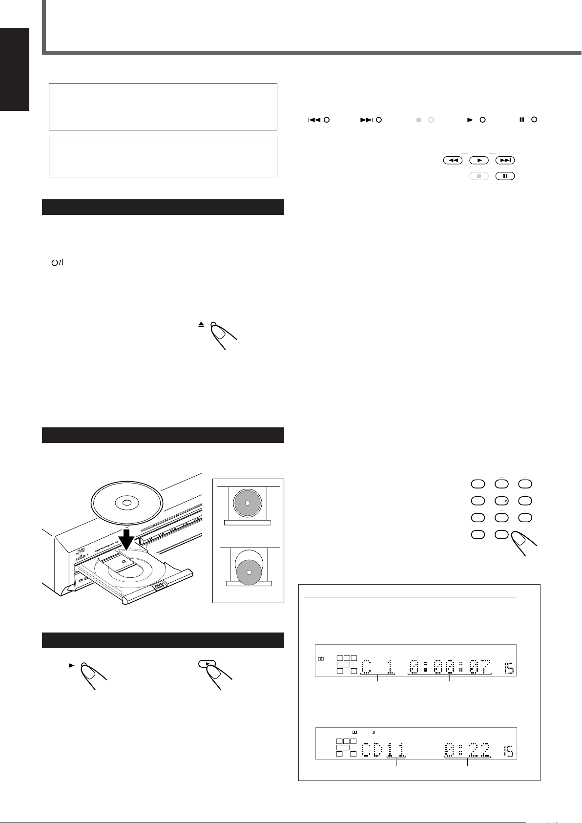
Basic DVD Player Operations ...................... 15
1 Open the Disc Tray .............................................................. 15
2 Load a Disc .......................................................................... 15
3 Start Playback ...................................................................... 15
4 Adjust the Volume ................................................................ 16
5 Activate Realistic Sound Field............................................. 16
6 Select Surround Mode ......................................................... 16
7 Stop Playback ...................................................................... 16
8 Turn Off the Power (into Standby) ...................................... 16
Tuner Operations ....................................... 17
Tuning into Stations Manually ................................................. 17
Using Preset Tuning ................................................................. 17
Selecting the FM Reception Mode ........................................... 18
Basic Settings ........................................... 19
Operation Buttons .................................................................... 19
Operating Procedure ................................................................. 19
7 Speaker information—“SUBWFR,” “FRNT SP,”
“CNTR SP,” and “REAR SP” ........................................... 20
7 Speaker distance
—“FRNT D,” “CNTR D,” and “REAR D” ...................... 20
7 Crossover frequency—“CROSS” ..................................... 21
7 Low frequency effect attenuator—“LFE” ........................ 21
7 Dynamic range compression—“D.COMP” ...................... 21
7 Digital input (DIGITAL IN) terminals—“DGT” ............. 21
7 Auto surround—“AUTO SR” ........................................... 22
7 Video output mode—“VOUT” ......................................... 22
Sound Adjustments.................................... 23
Operation Buttons .................................................................... 23
Operating Procedure ................................................................. 23
7 Front speaker output balance—“BAL” ............................. 24
7 Tone—“BASS” and “TREBLE” ...................................... 24
7 Speaker output levels—“SUBWFR,” “CENTER,”
“REAR L,” and “REAR R” .............................................. 24
7 DAP effect level—“EFFECT” .......................................... 24
Creating Realistic Sound Fields ................... 25
Activating Surround Mode ........................................................ 27
Selecting Surround Modes ........................................................ 27
Adjusting Surround Mode Using Remote Control................... 28
DVD Player Operations .............................. 29
Disc Information ....................................................................... 29
Using the On-screen Bar .......................................................... 31
Basic Operation through the On-screen Bar ............................ 32
Changing the Time Indication .................................................. 32
Locating a Desired Scene from the Disc Menu ....................... 33
Selecting a View Angle—ANGLE ........................................... 34
Changing the Languages—SUBTITLE and AUDIO ............... 35
Playing from a Specified Position on a Disc ............................ 37
7 Locating a desired chapter—Chapter Search ................... 37
7 Locating a desired position—Time Search ....................... 37
7 Locating a desired scene—DIGEST ................................. 38
Special Picture Playback .......................................................... 39
7 Frame-by-frame playback ................................................. 39
7 Showing continuous still pictures—STROBE .................. 39
7 Playing back in slow-motion ............................................ 39
7 Zooming in—ZOOM ........................................................ 39
7 Changing the VFP setting—VFP ...................................... 40
Program Playback and Random Playback ............................... 41
Repeat Playback ....................................................................... 42
MP3 Disc Playback .................................... 43
Basic Operations ...................................................................... 43
Operations through the MP3 CONTROL Screen .................... 44
Repeat Playback ....................................................................... 44
JPEG Disc Playback ................................... 45
Slide-show Playback ................................................................ 45
Operations through the JPEG CONTROL Screen ................... 46
Repeat Playback ....................................................................... 46
Choice Menu Operations............................. 47
Operation Buttons .................................................................... 47
Configuration of Choice Menu ................................................ 47
Operating Procedure ................................................................. 48
7 LANGUAGE menu .......................................................... 49
7 PICTURE menu ................................................................ 49
7 AUDIO menu .................................................................... 50
• Language code list ......................................................... 50
7 SPK. SETTING menu ...................................................... 51
7 OTHERS menu ................................................................. 52
Restricting Playback by Parental Lock .................................... 53
7 Setting Parental Lock ........................................................ 53
7 Changing the setting of Parental Lock ............................. 54
7 Releasing Parental Lock temporarily ................................ 54
• Country/Area codes list for Parental Lock ..................... 55
Glossary for DVD Player............................. 56
AV COMPU LINK Remote Control System .... 57
Operating JVC’s Audio/Video Components ........ 59
Operating Audio Components .................................................. 59
Operating Video Components .................................................. 60
Operating Other Manufacturers’ Equipment ..... 61
Changing the Preset Signal Codes ........................................... 61
Maintenance ............................................. 64
Troubleshooting ......................................... 65
Specifications ............................................ 68
1
Page 5
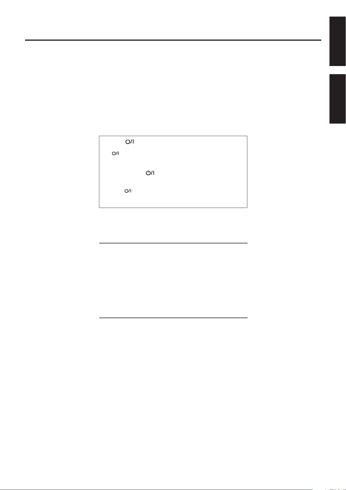
Parts Identification
MASTER VOLUME
DVD/SUPER VCD/VCD/CD
INPUT ATT.
INPUT
ANALOG/DIGITAL
COMPACT
SUPER VIDEO
SETTING ADJUST MEMORY
RX-DV3 HOME THEATER DVD/CD RECEIVER
ON/OFF
SURROUND
MODE
FM/AMTAPE/CDR
SOURCE NAME
TVVCRDBSDVD
CONTROL
STANDBY
STANDBY/ON
12436
7pwertyq
REC MODE
8 9
5
PRO LOGIC
DIGITAL
AUTO
SURROUND
12 3 4 5
ANALOG DIGITAL AUTO
PRO LOGIC
DSP PROGRAM REPEAT RANDOM1A-B PROGRESSIVE INPUT ATT
LS RSS
LFE
LCR
SUBWFR
VOLUME
RESUME SPK.
kHz
MHz
TUNED STEREO AU TO MUTING SLEEP
67 98-=~!@0
DIGITAL
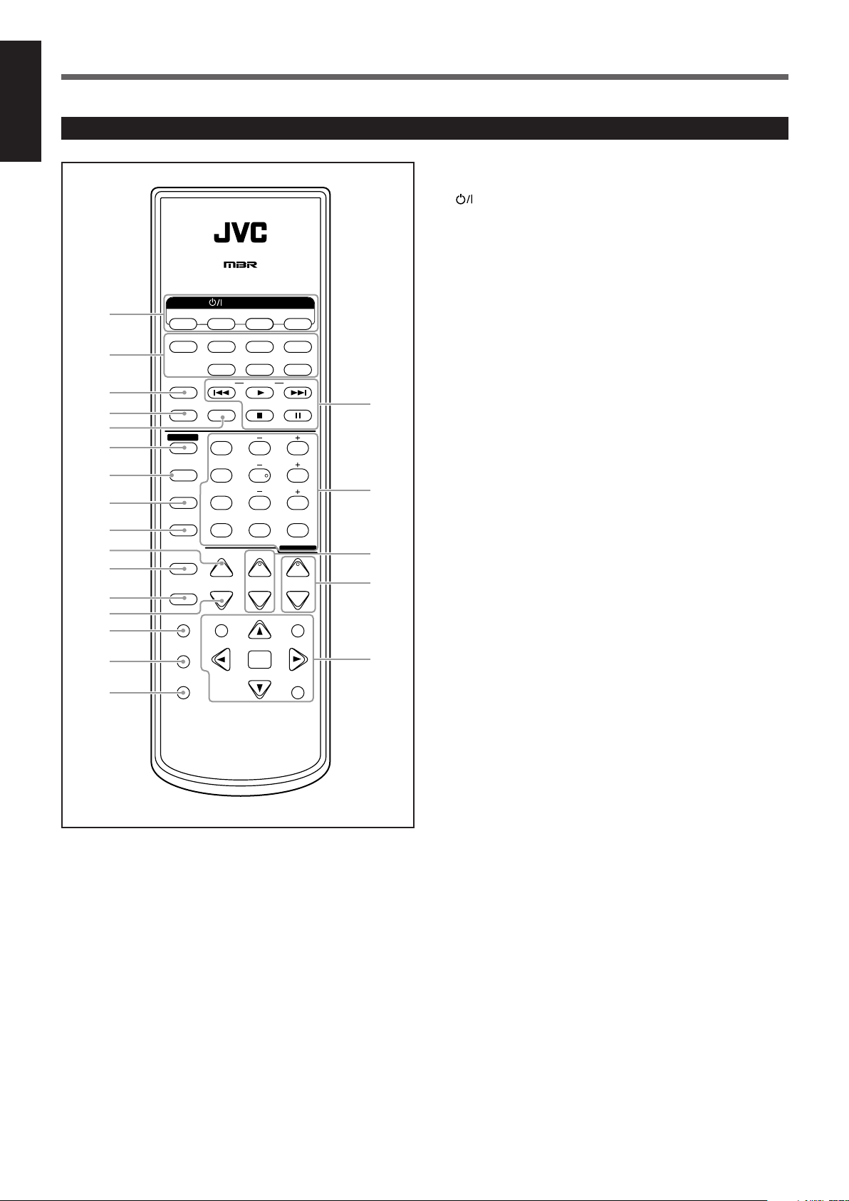
Front Panel
See pages in the parentheses for details.
1 STANDBY/ON button and STANDBY lamp (11)
2 Disc tray and illumination lamp (15)
3 DVD player operation buttons
0 (open/close), 4 (reverse skip), ¢ (forward skip),
7 (stop), 3 (play), 8 (pause)
4 Source selecting buttons (11, 13)
• DVD, DBS, VCR, TV, TAPE/CDR, FM/AM
5 SOURCE NAME button (12)
6 MASTER VOLUME control (11, 16)
7 INPUT ANALOG/DIGITAL button (13)
INPUT ATT. (Attenuator) button (14)
8 SURROUND ON/OFF button (16, 27)
9 SURROUND MODE button (16, 27)
REC MODE button (14)
p Display
• For details, see “Display” below.
q SETTING button (19 – 22)
w ADJUST button (23, 24)
e MEMORY button (17)
r CONTROL 5 / ∞ / 2 / 3 buttons (17 – 24)
(phones) jack (11)
t
y Remote sensor
English
Display
1 Input mode indicators (13)
• ANALOG, DIGITAL AUTO
2 Surround mode indicators (25, 26)
•
3 Play mode indicators (41, 42, 44, 46)
• PROGRAM, REPEAT 1A-B, RANDOM
4 PROGRESSIVE indicator (14)
5 INPUT ATT indicator (14)
6 Sound signal indicators (13)
•
7 Signal and speaker indicators (27)
• L, C , R, SUBWFR (Subwoofer), LFE (Low Frequency Effect),
LS, S, RS
, DSP
(Dolby Digital), (DTS Digital Surround)
8 Surround indicators (27)
• AUTO SURROUND, SURROUND
9 RESUME indicator (16)
0 SPK. (speaker) indicator (11)
- Main display
= Tuner mode indicators (17, 18)
• TUNED, STEREO, AUTO MUTING
~ SLEEP indicator (12)
! Frequency unit indicators
• MHz (for FM station), kHz (for AM station)
@ VOLUME indication
2
Page 6
Parts Identification
+
–
+
–
231
564
89
7
VFP
10/0 +10
100+ TV RETURN
REMOTE CONTROL RM-SRXDV3J
VCRDBS DVD
TV/VIDEO REW/(TUNING
9
/FF
REPEAT SLEEP
VCRDBS TV AUDIO
TAPETV CDR FM/AM
FM MODE STROBE
EFFECT
– TV/DBS CH +
ANALOG
/DIGITAL
TEST
AUDIO
INPUT
SUBTITLE
CHOICE
ENTER
ON SCREEN
ANGLE
ZOOM
DIGEST TOP MENU MENU
RETURN
SURR ON/OFF
SURR MODE
DIMMER
MUTING
TV VOL VOLUME
–
SUBWOOFER
+
HOME THEATER
DVD/CD RECEIVER
SOUND
PROGRESSIVE
STANDBY/ON
CENTER
REAR·L
REAR·R
1
2
3
4
6
8
9
p
q
w
e
r
t
y
u
i
o
;
a
5
7
English
Remote Control
See pages in the parentheses for details.
STANDBY/ON buttons (11, 60 – 63)
1
• DBS, VCR, TV, AUDIO
2 Source selecting buttons (11, 13, 59 – 63)
• TV, TAPE, CDR, FM/AM, DBS, VCR, DVD
3 TV/VIDEO button (15, 60, 61)
4 REPEAT button (42, 44, 46)
5 SLEEP button (12)
6 SOUND button (24, 27, 28)
7 ANALOG/DIGITAL INPUT button (13)
8 AUDIO button (35, 36)
9 SUBTITLE button (35)
p DIMMER button (12)
q ANGLE button (34)
w ZOOM button (39)
e MUTING button (12)
r DIGEST button (38)
t CHOICE button (47, 48)
y ON SCREEN button (31, 32, 34 – 38, 41, 42)
u Multi operation buttons
• 4, 3, ¢, 7, 8, REW, FF
• TUNING 9 and ( buttons (17)
• FM MODE button (18)
• STROBE button (39)
• TV/DBS CH (channel) + and – buttons (60, 61)
i Number buttons
• For selecting preset channels (18)
• For adjusting sound (24, 28, 59)
• For operating audio/video components (59 – 63)
• SURR (surround) ON/OFF button (16, 27)
• SURR (surround) MODE button (16, 27)
• VFP button (40)
• TV RETURN button (60, 61)
• PROGRESSIVE button (14)
o TV VOL (volume) + and – buttons (60, 61)
; VOLUME + and – buttons (11, 16)
a Menu operation buttons
• TOP MENU button (33)
• MENU button (33)
• RETURN button (33)
• ENTER button
• Cursor 5/∞/3/2 buttons
3
Page 7
Getting Started
Before Installation
General Precautions
• DO NOT insert any metal object into the unit.
• DO NOT disassemble the unit or remove screws, covers, or
cabinet.
• DO NOT expose the unit to rain or moisture.
Locations
• Install the unit in a location that is level and protected from
moisture.
• The temperature around the unit must be between –5˚C and 35˚C
(23˚F and 95˚F).
• Make sure there is good ventilation around the unit. Poor
ventilation could cause overheating and damage the unit.
Handling the unit
• DO NOT touch the power cord with wet hands.
• DO NOT pull on the power cord to unplug it. When unplugging
the cord, always grasp the plug so as not to damage the cord.
• Keep the power cord away from the connecting cords and the
antenna. The power cord may cause noise or screen interference. It
is recommended to use a coaxial cable for antenna connection,
since it is well-shielded against interference.
• When a power failure occurs, or when you unplug the power cord,
the preset settings such as preset FM or AM channels and sound
adjustments may be erased in a few days.
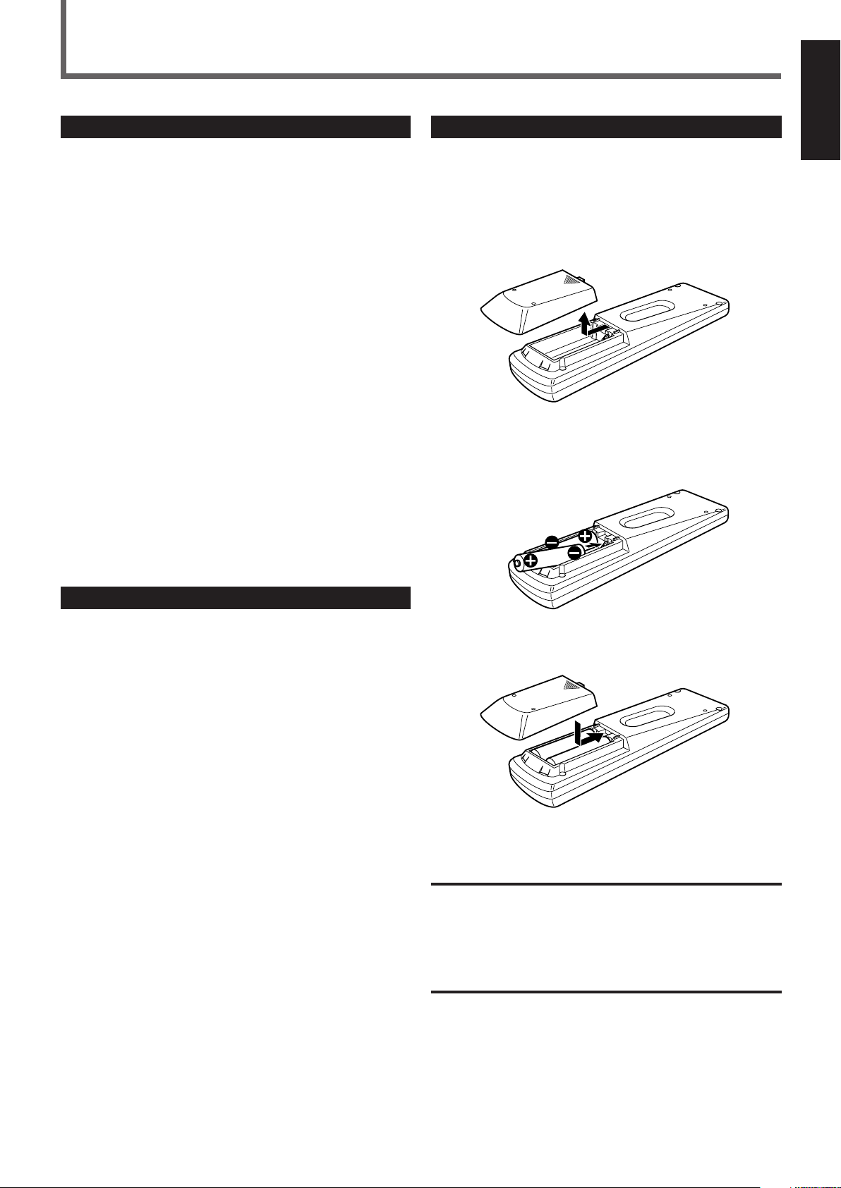
Putting Batteries in the Remote Control
Before using the remote control, put two supplied batteries first.
• When using the remote control, aim the remote control directly at
the remote sensor on the unit.
1
On the back of the remote control, remove the
battery cover.
2
Insert batteries. Make sure to match the polarity:
(+) to (+) and (–) to (–).
English
Checking the Supplied Accessories
Check to be sure you have all of the following supplied accessories.
The number in the parentheses indicates the quantity of the pieces
supplied.
• Remote Control (1)
• Batteries (2)
• AM Loop Antenna (1)
• FM Antenna (1)
• Composite Video Cord (1)
If anything is missing, contact your dealer immediately.
3
Replace the cover.
If the range or effectiveness of the remote control decreases, replace
the batteries. Use two R6P(SUM-3)/AA(15F) type dry-cell batteries.
CAUTION:
Follow these precautions to avoid leaking or cracking cells:
• Place batteries in the remote control so they match the polarity:
(+) to (+) and (–) to (–).
• Use the correct type of batteries. Batteries that look similar may
differ in voltage.
• Always replace both batteries at the same time.
• Do not expose batteries to heat or flame.
4
Page 8
Getting Started
AM LOOP
FM 75
COAXIAL
AM EXT
SUB-
WOOFER
OUT
DIGITAL 1
(DBS)
DIGITAL 2
(TV)
PCM/STREAM
FRONT
SPEAKERS
REAR
SPEAKERS
CENTER
SPEAKER
DIGITAL IN
DVD COMPONENT VIDEO OUT
ANTENNA
TV TAPE / CDR DBS VCR
AUDIO
S-VIDEO VIDEO
YPB PR
DBS
IN
DBS
IN
MONITOR
OUT
MONITOR
OUT
CAUTION:
SPEAKER
IMPEDANCE
816
RIGHT LEFT
AV COMPU LINK-
RIGHT
LEFT
IN INOUT
(REC)IN(PLAY)
OUT
(REC)IN(PLAY)
DIGITAL OUT
VCR
OUT
(REC)IN(PLAY)
VCR
OUT
(REC)IN(PLAY)
RIGHT LEFT
FM 75
COAXIAL
ANTENNA
AM LOOP
FM 75
COAXIAL
AM EXT
B
FM 75
COAXIAL
1
23
1
2
English
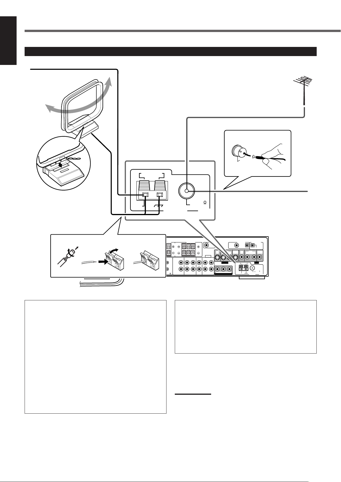
Connecting the FM and AM Antennas
AM loop antenna
(supplied)
Snap the tabs on the loop into
the slots of the base to
assemble the AM loop antenna.
If AM reception is poor,
connect an outdoor
single vinyl-covered wire
(not supplied).
If FM reception is poor, connect
outdoor FM antenna (not supplied).
FM antenna (supplied)
AM antenna connection
Connect the AM loop antenna supplied to the AM LOOP
terminals.
1
Remove the insulation if the AM loop antenna
wire is covered with vinyl.
2
Press and hold the clamp of the terminal (1),
then insert the wire (2).
3
Release the clamp.
Turn the loop until you have the best reception.
• If the reception is poor, connect an outdoor single vinylcovered wire (not supplied) to the AM EXT terminal. Keep the
AM loop antenna connected.
Rear panel of the unit
FM antenna connection
Connect the FM antenna supplied to the FM 75 Ω COAXIAL
terminal as temporary measure.
Extend the supplied FM antenna horizontally.
• If the reception is poor, connect an outdoor FM antenna (not
supplied). Before attaching a 75 Ω coaxial cable (with a
standard type connector), disconnect the supplied FM antenna.
Note:
• Make sure the antenna conductors do not touch any other
terminals, connecting cords and power cord. This could cause poor
reception.
5
Page 9
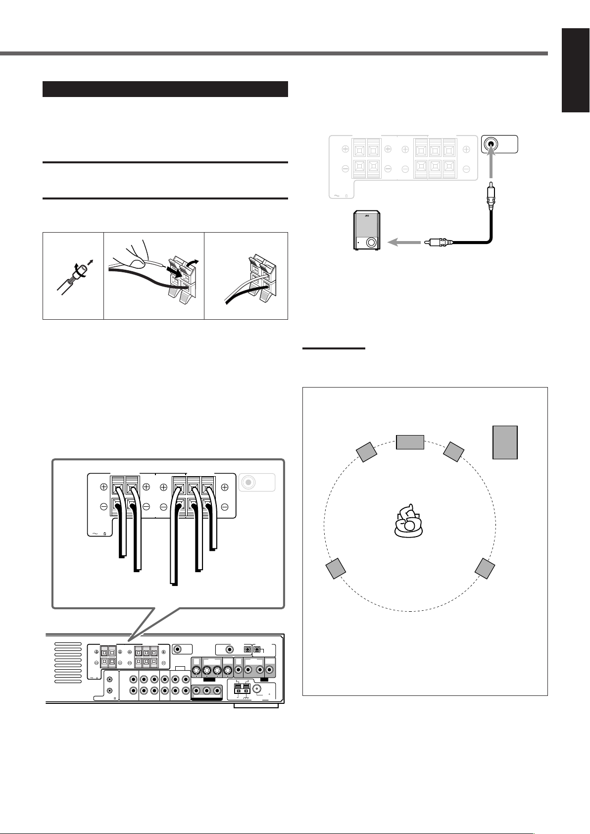
Connecting the Speakers
1
2
AM LOOP
FM 75
COAXIAL
AM EXT
SUBWOOFER
OUT
DIGITAL 1
(DBS)
DIGITAL 2
(TV)
PCM/STREAM
FRONT
SPEAKERS
REAR
SPEAKERS
CENTER
SPEAKER
DIGITAL IN
DVD COMPONENT VIDEO OUT
ANTENNA
TV TAPE / CDR DBS VCR
AUDIO
S-VIDEO VIDEO
YPBP
R
DBS
IN
DBS
IN
MONITOR
OUT
MONITOR
OUT
CAUTION:
SPEAKER
IMPEDANCE
816
RIGHT LEFT
AV COMPU LINK-
RIGHT
LEFT
IN INOUT
(REC)IN(PLAY)
OUT
(REC)IN(PLAY)
DIGITAL OUT
VCR
OUT
(REC)IN(PLAY)
VCR
OUT
(REC)IN(PLAY)
RIGHT LEFT
FRONT
SPEAKERS
REAR
SPEAKERS
CENTER
SPEAKER
CAUTION:
SPEAKER
IMPEDANCE
816
RIGHT LEFT RIGHT LEFT
SUBWOOFER
OUT
SUBWOOFER
OUT
FRONT
SPEAKERS
REAR
SPEAKERS
CENTER
SPEAKER
CAUTION:
SPEAKER
IMPEDANCE
816
RIGHT LEFT RIGHT LEFT
After connecting the front, center and rear speakers, and/or a
subwoofer, set the speaker setting information properly to obtain the
best possible Surround effect. For details, see page 20.
CAUTIONS:
• Use speakers with the SPEAKER IMPEDANCE indicated by the
speaker terminals (8 – 16 Ω).
• DO NOT connect more than one speaker to one speaker terminal.
Connecting the front, center, and rear speakers
1
2
3
Connecting the subwoofer speaker
By connecting a subwoofer, you can enhance the bass or reproduce
the original LFE signals recorded in the digital software.
Powered subwoofer
(example)
Connect the input jack of a powered subwoofer to the SUBWOOFER OUT jack on the rear panel, using a cable with RCA pin
plugs (not supplied).
• Refer also to the manual supplied with your subwoofer.
English
For each speaker, connect the (+) and (–) terminals on the rear panel
to the (+) and (–) terminals marked on the speakers respectively.
1
Cut, twist and remove the insulation at the end of
each speaker cord (not supplied).
2
Press and hold the clamp of the speaker terminal
(1), then insert the speaker cord (2).
3
Release the clamp.
To left rear
To right front
speaker
To left front speaker
To center speaker
speaker
To right rear
speaker
Note:
• You can place a subwoofer wherever you like since bass sound is
non-directional. Normally place it in front of you.
Speaker Layout Diagram
Subwoofer
Left front
speaker
Left rear
speaker
Center speaker
Right front
speaker
Right rear
speaker
To obtain the best possible sound from this system, place all the
speakers except the subwoofer at the same distance from the
listening position with each speaker’s front faced toward the
listener.
Then, change the subwoofer and speaker settings to fit your
listening conditions (see page 20).
6
Page 10
Getting Started
A
B
C
B
A
B
C
English
Connecting Audio/Video Components
Turn off all the components and the unit before connection.
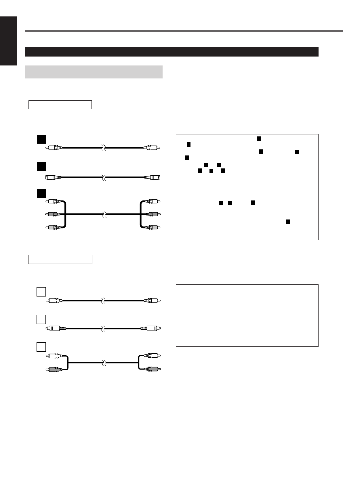
■ About connecting cords
For video connections
The S-video cords and the component video cord are not supplied with this unit.
Use the cords supplied with the other components or purchase them at your dealer.
Composite video cord (supplied)
S-video cord (not supplied)
Component video cord (not supplied)
Yellow
Green
Blue
Red
TV connection
• You can use composite video cord (A) and/or S-video cord
(B) for connecting DBS tuner and VCR to this unit.
• You can use component video cord (C) in addition to A and
for connecting your TV to this unit.
• By using B or C, you can get a better picture quality—in the
order: A < B < C.
• To view the picture from DBS tuner or VCR on your TV, connect
your TV to this unit using the same type of cord for connecting
DBS tuner or VCR to this unit.
• To view the picture from the built-in DVD player, connect the TV
to this unit using A, B, and/or C, then register the video
output mode correctly (see “Video output mode” on page 22).
• To enjoy the progressive video picture, connect the TV
compatible with the progressive video input using C, then
change the scanning mode correctly (see “Changing the
Scanning Mode” on page 14).
For audio connections
Connect the external components to this unit with the audio cords.
Use the cord supplied with the other components or purchase them at your dealer.
Digital coaxial cord (not supplied)
Optical digital cord (not supplied)
Audio cord (not supplied)
White
Red
• When the unit is shipped from the factory, the DIGITAL IN
terminals are set for use with the following components:
– DIGITAL 1 (coaxial): For DBS tuner
– DIGITAL 2 (optical): For TV
• If you connect CDR, change the digital input (DIGITAL IN)
terminal setting (see “Digital input (DIGITAL IN) terminals” on
page 21) and the source name (see “Changing the Source
Name” on page 12) correctly.
• Select the digital input mode correctly (see “Selecting the
Analog or Digital Input Mode” on page 13).
7
Page 11
Getting Started
DIGITAL
OPTICAL OUT
AM LOOP
FM 75
COAXIAL
AM EXT
SUBWOOFER
OUT
DIGITAL 1
(DBS)
DIGITAL 2
(TV)
PCM/STREAM
FRONT
SPEAKERS
REAR
SPEAKERS
CENTER
SPEAKER
DIGITAL IN
DVD COMPONENT VIDEO OUT
ANTENNA
TV TAPE / CDR DBS VCR
AUDIO
S-VIDEO VIDEO
YPBP
R
DBS
IN
DBS
IN
MONITOR
OUT
MONITOR
OUT
CAUTION:
SPEAKER
IMPEDANCE
816
RIGHT LEFT
AV COMPU LINK-
RIGHT
LEFT
IN INOUT
(REC)IN(PLAY)
OUT
(REC)IN(PLAY)
DIGITAL OUT
VCR
OUT
(REC)IN(PLAY)
VCR
OUT
(REC)IN(PLAY)
RIGHT LEFT
B
C
DIGITAL 1
(DBS)
DIGITAL 2
(TV)
DIGITAL IN
TV TAPE / CDR DBS VCR
AUDIO
RIGHT
LEFT
IN INOUT
(REC)IN(PLAY)
OUT
(REC)IN(PLAY)
LEFT
RIGHT
AUDIO
OUT
AM LOOP
FM 75
COAXIAL
AM EXT
SUB-
WOOFER
OUT
DIGITAL 1
(DBS)
DIGITAL 2
(TV)
PCM/STREAM
FRONT
SPEAKERS
REAR
SPEAKERS
CENTER
SPEAKER
DIGITAL IN
DVD COMPONENT VIDEO OUT
ANTENNA
TV TAPE / CDR DBS VCR
AUDIO
S-VIDEO VIDEO
YPBP
R
DBS
IN
DBS
IN
MONITOR
OUT
MONITOR
OUT
CAUTION:
SPEAKER
IMPEDANCE
816
RIGHT LEFT
AV COMPU LINK-
RIGHT
LEFT
IN INOUT
(REC)IN(PLAY)
OUT
(REC)IN(PLAY)
DIGITAL OUT
VCR
OUT
(REC)IN(PLAY)
VCR
OUT
(REC)IN(PLAY)
RIGHT LEFT
Y
P
B
P
R
A
B
C
DVD COMPONENT VIDEO OUT
YPBP
R
S-VIDEO VIDEO
VIDEO IN
DBS
IN
DBS
IN
MONITOR
OUT
MONITOR
OUT
VCR
OUT
(REC)IN(PLAY)
VCR
OUT
(REC)IN(PLAY)
COMPONENT VIDEO IN
Turn off all the components and the unit before connection.
■ TV connection
Video connections
DO NOT connect a TV through a VCR or a TV with a built-in
VCR; Otherwise, the picture may be distorted.
Illustrations of the input/output terminals below are typical
examples. When you connect other components, refer also to
their manuals since the terminal names actually printed on
their rear vary among the components.
English
Audio connections
Before connecting an
optical digital cord,
unplug the protective
plug.
Blue
Green
Red
Red
Green
Blue
White White
Red
Red
8
Page 12
Getting Started
AM LOOP
FM 75
COAXIAL
AM EXT
SUBWOOFER
OUT
DIGITAL 1
(DBS)
DIGITAL 2
(TV)
PCM/STREAM
FRONT
SPEAKERS
REAR
SPEAKERS
CENTER
SPEAKER
DIGITAL IN
DVD COMPONENT VIDEO OUT
ANTENNA
TV TAPE / CDR DBS VCR
AUDIO
S-VIDEO VIDEO
YPBP
R
DBS
IN
DBS
IN
MONITOR
OUT
MONITOR
OUT
CAUTION:
SPEAKER
IMPEDANCE
816
RIGHT LEFT
AV COMPU LINK-
RIGHT
LEFT
IN INOUT
(REC)IN(PLAY)
OUT
(REC)IN(PLAY)
DIGITAL OUT
VCR
OUT
(REC)IN(PLAY)
VCR
OUT
(REC)IN(PLAY)
RIGHT LEFT
C
TV TAPE / CDR DBS VCR
AUDIO
RIGHT
LEFT
IN INOUT
(REC)IN(PLAY)
OUT
(REC)IN(PLAY)
S-VIDEO VIDEO
DBS
IN
DBS
IN
MONITOR
OUT
MONITOR
OUT
VCR
OUT
(REC)IN(PLAY)
VCR
OUT
(REC)IN(PLAY)
B
OUT
VIDEO
OUT
S-VIDEO
LEFT
RIGHT
AUDIO
OUT
A
AM LOOP
FM 75
COAXIAL
AM EXT
SUBWOOFER
OUT
DIGITAL 1
(DBS)
DIGITAL 2
(TV)
PCM/STREAM
FRONT
SPEAKERS
REAR
SPEAKERS
CENTER
SPEAKER
DIGITAL IN
DVD COMPONENT VIDEO OUT
ANTENNA
TV TAPE / CDR DBS VCR
AUDIO
S-VIDEO VIDEO
YPBP
R
DBS
IN
DBS
IN
MONITOR
OUT
MONITOR
OUT
CAUTION:
SPEAKER
IMPEDANCE
816
RIGHT LEFT
AV COMPU LINK-
RIGHT
LEFT
IN INOUT
(REC)IN(PLAY)
OUT
(REC)IN(PLAY)
DIGITAL OUT
VCR
OUT
(REC)IN(PLAY)
VCR
OUT
(REC)IN(PLAY)
RIGHT LEFT
B
B
S-VIDEO VIDEO
VIDEO
OUTINOUTIN
S-VIDEO
DBS
IN
DBS
IN
MONITOR
OUT
MONITOR
OUT
VCR
OUT
(REC)IN(PLAY)
VCR
OUT
(REC)IN(PLAY)
A
TV TAPE / CDR DBS VCR
AUDIO
RIGHT
LEFT
IN INOUT
(REC)IN(PLAY)
OUT
(REC)IN(PLAY)
LEFT
RIGHT
AUDIO
OUT IN
C
C
English
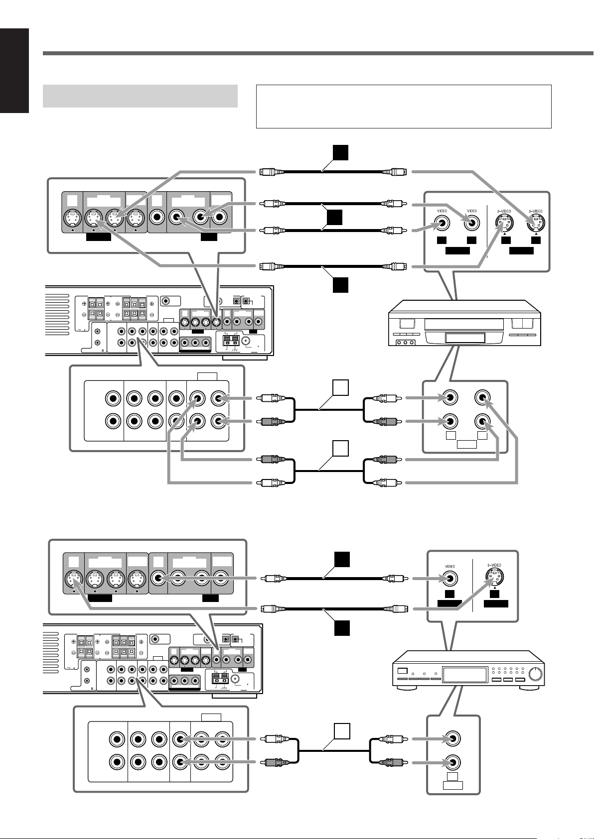
Turn off the TV and the unit before connection.
■ VCR connection
Illustrations of the input/output terminals below are typical examples.
When you connect other components, refer also to their manuals since the
terminal names actually printed on their rear vary among the components.
VCR
■ DBS tuner connection
9
White
Red
Red
White
White
Red
Red
White
DBS tuner
White
Red
White
Red
Page 13
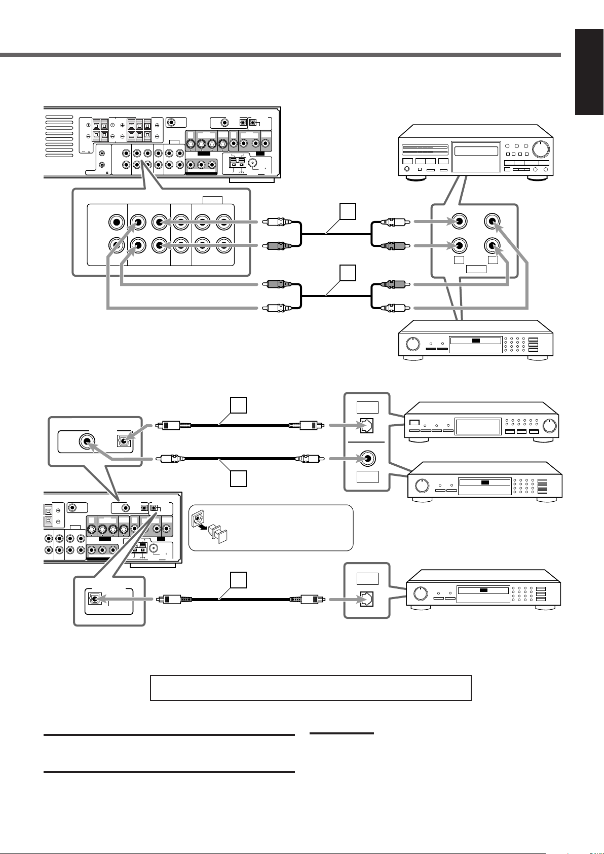
■ Cassette deck/CD recorder connection
AM LOOP
FM 75
COAXIAL
AM EXT
SUBWOOFER
OUT
DIGITAL 1
(DBS)
DIGITAL 2
(TV)
PCM/STREAM
FRONT
SPEAKERS
REAR
SPEAKERS
CENTER
SPEAKER
DIGITAL IN
DVD COMPONENT VIDEO OUT
ANTENNA
TV TAPE / CDR DBS VCR
AUDIO
S-VIDEO VIDEO
YPBP
R
DBS
IN
DBS
IN
MONITOR
OUT
MONITOR
OUT
CAUTION:
SPEAKER
IMPEDANCE
816
RIGHT LEFT
AV COMPU LINK-
RIGHT
LEFT
IN INOUT
(REC)IN(PLAY)
OUT
(REC)IN(PLAY)
DIGITAL OUT
VCR
OUT
(REC)IN(PLAY)
VCR
OUT
(REC)IN(PLAY)
RIGHT LEFT
TV TAPE / CDR DBS VCR
AUDIO
RIGHT
LEFT
IN INOUT
(REC)IN(PLAY)
OUT
(REC)IN(PLAY)
LEFT
RIGHT
AUDIO
INOUT
C
C
AM LOOP
FM 75
COAXIAL
AM EXT
SUBWOOFER
OUT
DIGITAL 1
(DBS)
DIGITAL 2
(TV)
PCM/STREAM
REAR
SPEAKERS
DIGITAL IN
DVD COMPONENT VIDEO OUT
ANTENNA
/ CDR DBS VCR
AUDIO
S-VIDEO VIDEO
YPBP
R
DBS
IN
DBS
IN
MONITOR
OUT
MONITOR
OUT
LEFT
ININ
(PLAY)
OUT
(REC)IN(PLAY)
DIGITAL OUT
VCR
OUT
(REC)IN(PLAY)
VCR
OUT
(REC)IN(PLAY)
DIGITAL 1
(DBS)
DIGITAL 2
(TV)
DIGITAL IN
A
B
DIGITAL
OUT
DIGITAL
IN
DIGITAL
OUT
B
PCM/STREAM
DIGITAL OUT
English
Cassette deck
■ Digital connection
White
Red
Red
White
Before connecting an optical
digital cord, unplug the
protective plug.
White
Red
Red
White
CD recorder
DBS tuner
CD recorder
Now, you can plug the power cord of the unit into the AC outlet.
CAUTIONS:
• Do not touch the power cord with wet hands.
• Do not pull on the power cord to unplug the cord. When unplugging
the cord, always grasp the plug so as not to damage the cord.
CD recorder
Notes:
• Keep the power cord away from the connecting cords and the
antenna cables. The power cord may cause noise or screen
interference.
• The preset settings such as preset channels and sound adjustment
may be erased in a few days in the following cases:
– When you unplug the power cord.
– When a power failure occurs.
10
Page 14
STANDBY
STANDBY/ON
VCRDBS TV AUDIO
STANDBY/ON
MASTER VOLUME
+
–
VOLUME
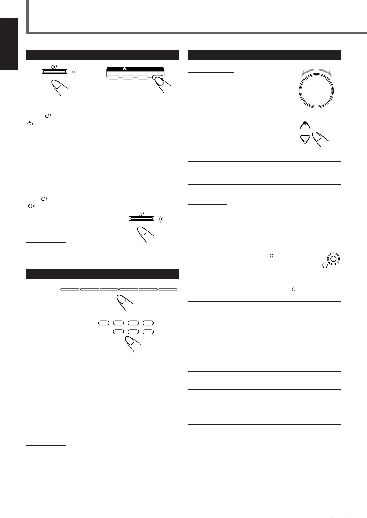
Basic Operations
STANDBY
STANDBY/ON
FM/AMTAPE/CDR
SOURCE NAME
TVVCRDBSDVD
VCRDBS DVD
TAPETV CDR FM/AM
English
1
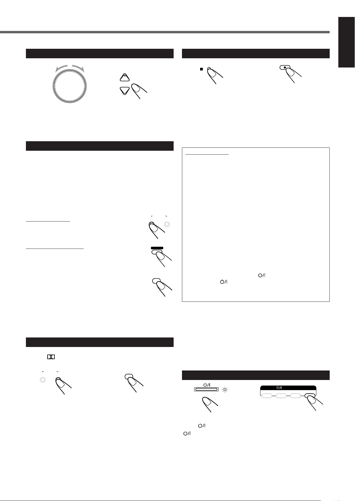
Turn On the Power
On the front panel From the remote control
Press
STANDBY/ON on the front panel or
STANDBY/ON AUDIO on the remote control.
The STANDBY lamp goes off and the illumination lamp lights up.
The current source name appears on the display.
• If the built-in DVD player is the current source, “READING”
appears while the unit is detecting the type of the loaded disc
(see page 29).
– Playback starts automatically when you load some DVD
VIDEO.
–“NO DISC” appears on the display when no disc is loaded.
To turn off the power (into standby)
Press
The illumination lamp goes off and the
STANDBY lamp lights up.
STANDBY/ON on the front panel or
STANDBY/ON AUDIO on the remote control again.
3
Adjust the Volume
On the front panel:
To increase the volume,
turn MASTER VOLUME clockwise.
To decrease the volume,
turn MASTER VOLUME counterclockwise.
From the remote control:
To increase the volume,
press and hold VOLUME +.
To decrease the volume,
press and hold VOLUME –.
CAUTION:
Always set the volume to the minimum before starting any sources. If
the volume is set at a high level, the sudden blast of sound energy
can permanently damage your hearing and/or ruin your speakers.
Notes:
• The volume level can be adjusted within the range of “0” (minimum)
to “50” (maximum).
• When DVD is selected as the source with your TV turned on, the
volume level indication appears on the TV.
Note:
• A small amount of the power is consumed even in standby mode.
To turn off the power completely, unplug the AC power cord.
2
Select the Source to Play
On the front panel
From the remote control
Press one of the source selecting buttons.
DVD : Select the built-in DVD player.
DBS* : Select the DBS tuner.
VCR : Select the VCR.
TV* : Select the TV tuner.
TAPE/CDR* : Select the cassette deck or the CD recorder (front
panel ONLY)
TAPE : Select the cassette deck (remote control ONLY**).
CDR* : Select the CD recorder (remote control ONLY**).
FM/AM : Select an FM or AM broadcast.
Listening with headphones
Connect a pair of headphones to the (phones) jack on the
front panel. This cancels the Surround mode currently
selected, deactivates speakers, and activates the
HEADPHONE mode.
The SPK. indicator goes off from the display.
• Disconnecting a pair of headphone from the
cancels the HEADPHONE mode and activates speakers.
HEADPHONE mode
When using the headphones, the following signals are output
regardless of your speaker setting:
— For 2-channel sources, the front left and right channel signals
are output directly from the left and right headphones.
— For multichannel sources, the front left and right, center and
rear channel signals are down-mixed and then output from the
headphones without missing bass element.
You can enjoy multichannel sound source using the
headphones.
CAUTION:
Be sure to turn down the volume:
• Before connecting or putting on headphones, as high volume can
damage both the headphones and your hearing.
• Before removing headphones, as high volume may output from the
speakers.
(phones) jack
Notes:
*
Register the digital input terminal setting (see “Digital input
(DIGITAL IN) terminals” on page 21) and digital input mode setting
correctly (see “Selecting the Analog or Digital Input Mode” on page
13). Source name and “DIGITAL” will be shown on the display when
you select the source.
**
When the source name is not assigned correctly, these buttons
cannot work (see “Changing the Source Name” on page 12).
11
Page 15
Turning Off the Sounds Temporarily
DIMMER
MUTING
SLEEP
DIGITAL AUTO
SPK.
L R
DIGITAL AUTO
VOLUME
SPK. SLEEP
10 20 30 60
120 901500 (off)
LR
TAPE/CDR
SOURCE NAME
ANALOG
VOLUME
ASSGN. TAPE ASSGN. CDR
LR
Changing the Display Brightness
English
From the remote control ONLY
Press MUTING to mute the sound.
“MUTING” appears on the display and the volume turns off (the
VOLUME indication goes off).
• When DVD is selected as the source with your TV turned on,
“VOLUME –” appears on the TV.
To restore the sound
Press MUTING again.
• Pressing VOLUME + or – on the remote control (or turn
MASTER VOLUME on the front panel) also restores the sound.
Turning Off the Power
with the Sleep Timer
From the remote control ONLY
From the remote control ONLY
Press DIMMER to dim the display.
• Each time you press the button, the display and
illumination lamp dim and brighten alternately.
Changing the Source Name
When you connect an CD recorder to the TAPE/CDR jacks on the
rear panel, change the source name which will be shown on the
display.
On the front panel ONLY
Ex. : When changing the source name from “TAPE ” to “CDR”
1
Press TAPE/CDR (SOURCE NAME) to select as
the source.
Press SLEEP repeatedly.
The SLEEP indicator lights up on the display.
• Each time you press the button, the shut-off time changes as
follows:
SLEEP indicator
When the shut-off time comes
The unit is turned off automatically.
To check or change the remaining time until the shut-off time
Press SLEEP once.
The remaining time (in minutes) until the shut-off time appears.
• To change the shut-off time, press SLEEP repeatedly.
To cancel the Sleep Timer
Press SLEEP repeatedly until “SLEEP 0” appears on the display.
(The SLEEP indicator goes off.)
• Turning off the unit also cancels the Sleep Timer.
2
Press and hold SOURCE NAME (TAPE/CDR)
until “ASSGN. CDR” appears on the display.
To change the source name to “TAPE”
Press and hold SOURCE NAME (TAPE/CDR) until “ASSGN.
2
TAPE” appears on the display in step
Note:
• Without changing the source name, you can still use the connected
components. However, there may be some inconveniences:
– The unexpected source name will appear on the display when
you press TAPE/CDR (SOURCE NAME) on the front panel.
– The CDR or TAPE button on the remote control cannot work for
selecting the source.
– You cannot use the digital input (see page 10) for the CD
recorder.
.
Note:
• If Auto Standby (see page 52) and Sleep Timer are used at a time,
one with the early shut-off time will turn off the unit.
12
Page 16
DIGITAL
Basic Operations
DIGITAL
FM/AMTAPE/CDR
SOURCE NAME
TVVCRDBSDVD
VCRDBS DVD
TAPETV CDR FM/AM
CONTROL
DIGITAL AUTO
VOLUME
DGTL AUTO DGTL D.D.
DGTL DTS
LR
ANALOG
/DIGITAL
INPUT
INPUT ATT.
INPUT
ANALOG/DIGITAL
ANALOG
/DIGITAL
INPUT
ANALOG DIGITAL AUTO
VOLUME
SPK.
DGTL AUTO ANALOG
LR
English
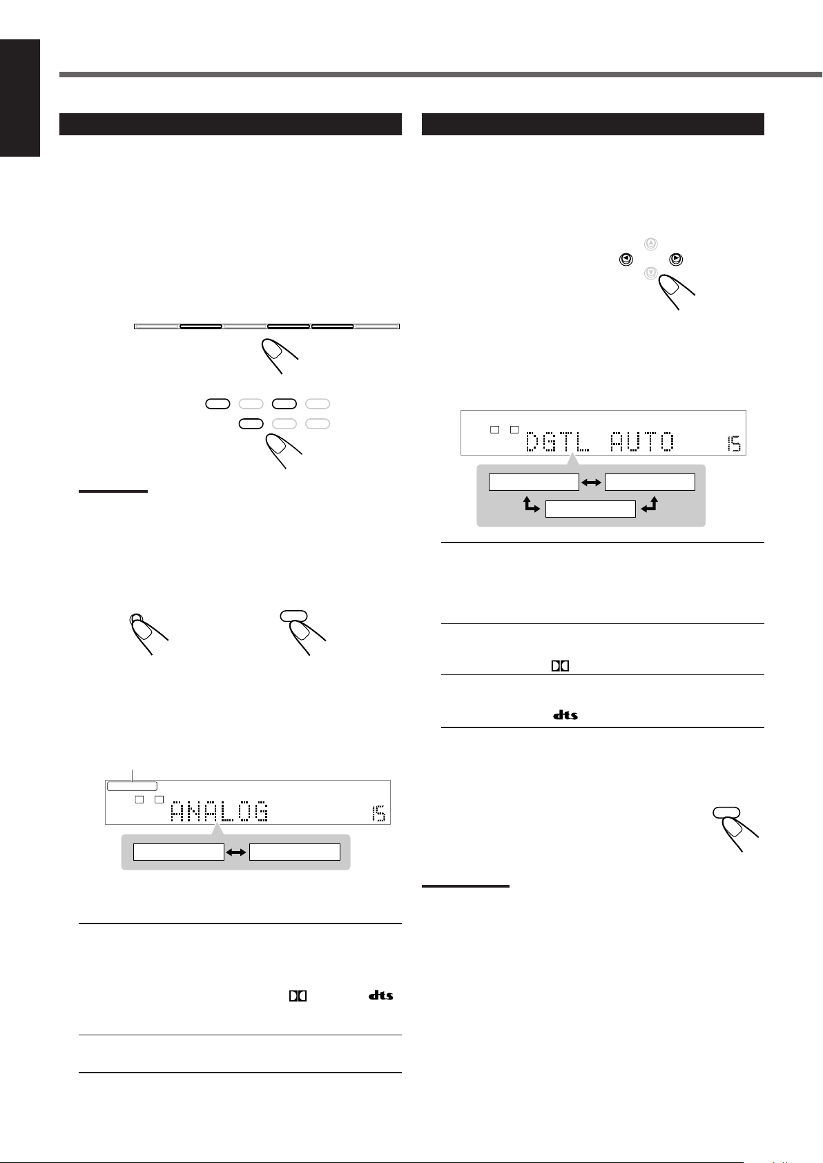
Selecting the Analog or Digital Input Mode
When you have connected digital source components using both the
analog connection and the digital connection methods (see pages 7 to
10), you can select the input mode.
• Before selecting the digital input mode, register the digital input
terminal setting correctly (see “Digital input (DIGITAL IN)
terminals” on page 21).
1
Press one of the source selecting buttons (DBS,
TV, or CDR) for which you want to change the
input mode.
On the front panel
From the remote control
Note:
•
You cannot change the input mode when selecting DVD as the
source. Digital input is always used for the built-in DVD player.
Changing the Digital Input Mode Manually
If the following symptoms occur while Dolby Digital or DTS
Digital Surround software is played back, you can change the digital
input mode:
• Sound does not come out at the beginning of playback.
• Noise comes out while searching for or skipping chapters or
tracks.
On the front panel
Press CONTROL 3 (or 2) to select “DGTL D.D.”
or “DGTL DTS” while “DGTL AUTO” still remains
on the display.
• Each time you press the button, the digital input mode changes as
follows:
2
Press INPUT ANALOG/DIGITAL (INPUT ATT.)
on the front panel or ANALOG/DIGITAL INPUT
on the remote control.
On the front panel From the remote control
The current input mode appears on the display.
• Each time you press the button, the input mode alternates
between the analog input (“ANALOG”*) and the digital input
(“DGTL AUTO”).
ANALOG/DIGITAL AUTO indicator
* “ANALOG” is the initial setting except for the built-in DVD
player.
DGTL AUTO : Select this for the digital input mode.
ANALOG : Select this for the analog input mode.
13
The DIGITAL AUTO indicator lights up.
The unit automatically detects the incoming
signal format, then the sound signal indicator
for the detected signal—
or
lights up; otherwise, no sound signal indicators
light up.
The ANALOG indicator lights up.
DGTL AUTO : Normally select this.
The DIGITAL AUTO indicator lights up.
The unit automatically detects the incoming
signal format, then the sound signal indicator
for the detected signal lights up.
DGTL D.D. : Select this for playing back software encoded
with Dolby Digital.
The
indicator lights up*.
DGTL DTS : Select this for playing back software encoded
with DTS Digital Surround.
The indicator lights up*.
* These indicators flash when no signal or the signal without the
proper format is played back.
When DVD is selected as the source, you can also
change the digital input mode by pressing
ANALOG/DIGITAL INPUT repeatedly on the remote
control.
Notes:
• When “DGTL AUTO” cannot recognize the incoming signals, no
sound signal indicators light up on the display.
• When you turn off the unit or select another source, “DGTL DTS”
and “DGTL D.D.” are canceled.
The digital input mode is automatically reset to “DGTL AUTO.”
Page 17
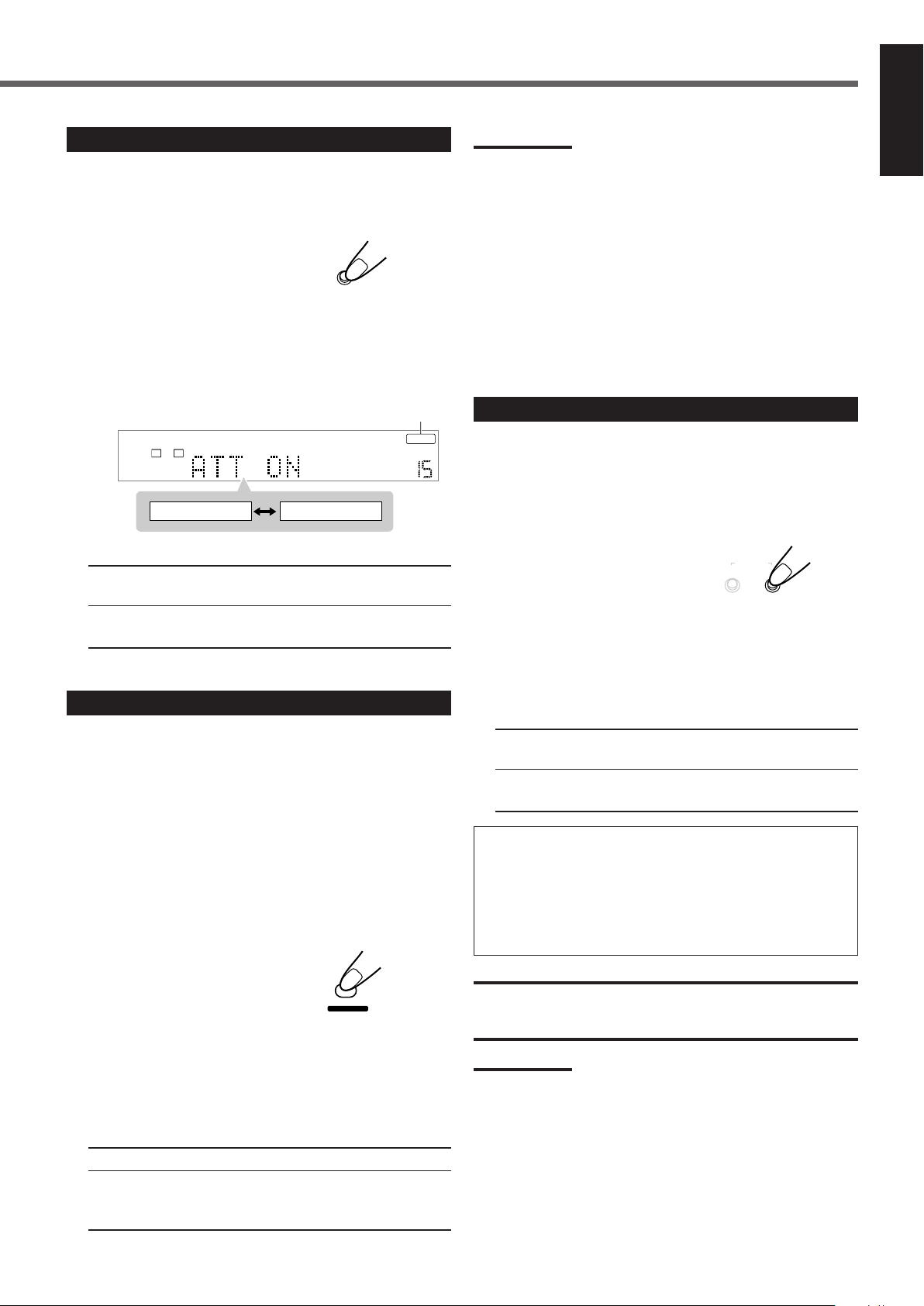
Attenuating the Input Signal
INPUT ATT.
INPUT
ANALOG/DIGITAL
ANALOG INPUT ATT
VOLUME
ATT NORMAL ATT ON
L R
PROGRESSIVE
VFP
TV RETURN
ON/OFF
SURROUND
MODE
REC MODE
When the input level of the analog source is too high, the sounds
will be distorted. If this happens, you need to attenuate the input
signal level to prevent the sound distortion.
• You have to make this adjustment for each analog source.
On the front panel ONLY
Press and hold INPUT ATT. (INPUT ANALOG/
DIGITAL) until the INPUT ATT indicator lights up
on the display.
• Each time you press and hold the button, the Input Attenuator
turns on (“ATT ON”) or off (“ATT NORMAL”*).
INPUT ATT indicator
* “ATT NORMAL” is the initial setting.
Notes:
• Some progressive TVs and High-Definition TVs are not fully
compatible with this system. When a DVD VIDEO is played back in
the progressive scanning mode on those TVs, the unnatural picture
may be in a result. In such a case, change the scanning mode to
“INTERLACE.” To check the compatibility of your TV, contact your
dealer. All JVC progressive TVs and High-Definition TVs are fully
compatible with this system respectively.
• When you select “PROGRESSIVE” as the scanning mode, the
picture does not come out correctly through composite video and
S-video jacks.
*
480p and 480i indicate the number of scanning lines and scanning
format of an image signal.
– 480p indicates 480 scanning lines with progressive format.
– 480i indicates 480 scanning lines with interlaced format.
Activating the Recording Mode
When you play back the multichannel sources, Recording mode
enables you to record the sounds without missing surround elements
by down-mixing the center and rear channel signals into the front
channel signals.
• When the multichannel software is played back with Recording
mode activated, the sounds are down-mixed and come out through
the front speakers only.
English
ATT NORMAL : Normally select this. The analog sound is not
attenuated.
ATT ON : Select this when the analog sound is
distorted.
Changing the Scanning Mode
This unit supports the progressive scanning system (480p*) as well
as the conventional interlaced scanning system (480i*).
If your TV has component video jacks and supports the progressive
video input, you can enjoy a high quality picture from the built-in
DVD player.
• Refer also to the instruction manuals supplied with your TV.
• You can select the progressive mode according to the original
picture type (film or video source). See page 49.
• Do not change the scanning mode to “PROGRESSIVE” in the
following cases:
– When your TV does not support the progressive video input.
– When you do not connect your TV to the unit using component
video cord.
From the remote control ONLY
Press and hold PROGRESSIVE for more than 3
seconds when DVD is selected as the source.
The current scanning mode appears on the display for a while.
• Each time you press and hold the button, the scanning mode
changes “INTERLACE”* and “PROGRESSIVE” alternately.
* “INTERLACE” is the initial setting.
INTERLACE : Select this for conventional TV.
PROGRESSIVE : Select this if your TV with component
jacks supports the progressive video input.
The PROGRESSIVE indicator lights up.
On the front panel ONLY
Press and hold REC MODE (SURROUND MODE)
until “RECMODE ON” appears on the display.
• Each time you press and hold the button, Recording mode is
activated (“RECMODE ON”) and deactivated
(“RECMODE OFF”*) alternately.
* “RECMODE OFF” is the initial setting.
RECMODE OFF : Normally select this. The down-mixing is
canceled.
RECMODE ON : Select this for recording the down-mixed
sounds.
When recording with VCR:
You can record the picture on your video tape without the volume
level indication when Recording mode is activated.
• When you do not want to record the on-screen guide icons, see
page 52.
• The choice menu and on-screen bar are always recorded when
they appears on the TV.
CAUTION:
When the front speakers are small, the output sound may be distorted
by Recording mode. In this case, decrease the volume until the sound
distortion diminishes.
Notes:
• When you turn off the unit or select another source, Recording
mode is canceled (“RECMODE OFF”).
• Sound adjustments (see pages 23 and 24) and Surround modes
(see pages 25 to 28) do not affect the recording.
• The following buttons do not work while Recording mode is
activated (“RECMODE ON”):
– SETTING and ADJUST on the front panel
– SURROUND ON/OFF and SURROUND MODE on the front
panel
– Number buttons for adjusting sound on the remote control
14
Page 18
Basic DVD Player Operations
REW/( TUNING
9/FF
FM MODE STROBE
– TV/DBS CH +
RX-DV3 HOME THEATER DVD/CD RECEIVER
TAPE/CDR
SOURCE NAME
TV
VCR
DBS
DVD
STANDBY
S
T
AN
D
B
Y
/O
N
IN
P
U
T A
TT.
INPUT
ANALOG/DIGITAL
D
I
G
IT
A
L
S
U
R
R
O
U
N
D
O
N
/OF
F
SURROUND
M
O
D
E
TUNING
SPK.
DIGITAL AUTO
VOLUME
PRO LOGIC
LR
SUBWFR
231
564
89
7
10/0 +10
100+
EFFECT
TEST
SURR ON/OFF
SURR MODE
–
SUBWOOFER
+
CENTER
REAR·L
REAR·R
DIGITAL AUTO
VOLUME
DIGITAL
AUTO
SURROUND
SPK.
LFE
LS RS
LCR
SUBWFR
English
For details about DVD player operations, see pages 29 to
42.
• You can also play back MP3 and JPEG files. See pages 43
to 46.
• When using remote control, press DVD to change the
remote control operation mode to the DVD player
operation.
1
Open the Disc Tray
Before turning on the unit, turn on your TV and select the correct
video input (see the manual supplied with your TV).
• When you use a JVC’s TV, you can turn on your TV by pressing
STANDBY/ON TV on the remote control and select the
video input by pressing TV/VIDEO. (If your TV is not a JVC’s,
see “Operating Other Manufacturers’ Equipment” on page 61.)
• For changing the OSD messages—the information on the TV
—into the desired language, see pages 47 and 49.
On the front panel ONLY
Press 0.
The unit is turned on and the disc tray opens.
The STANDBY lamp goes off and the illumination lamp lights up.
• When a disc is already loaded, pressing 3 turns on the unit and
starts playing back the loaded disc.
2
Load a Disc
Place a disc correctly with its label side up.
By pressing the following buttons, you can pause, advance, or reverse
playback, and locate the beginning of the title, chapter, or track.
On the front panel
From the remote control
To stop playback temporarily
Press 8.
• Pressing 3 starts playback again.
To move back the playback position by 10 seconds
(for DVD VIDEO only)
Press 3 during DVD VIDEO playback.
The unit moves the playback position about 10 seconds before the
current position, then resumes playback.
To advance or reverse playback rapidly
Press and hold ¢ or 4.
While you are pressing and holding ¢ (or 4), the unit advances
(or reverses: for DVD VIDEO and audio CD) playback 5 times as
fast as the normal speed. When you press and hold ¢ (or 4)
further, the playback speed changes up to 20 times as fast as the
normal speed.
• Releasing the button resumes the normal playback.
To locate the beginning of the chapter or track
Press ¢ or 4.
Press ¢ (or 4) to locate the beginning of the next (current or
previous) chapter or track.
To locate the chapter or track using the number buttons
Press the number buttons (1–10, +10) to select the number of the
desired chapter or track.
Ex. : To select 3, press 3.
To select 11, press +10, then 1.
To select 20, press +10, then 10.
CORRECT
INCORRECT
3
Start Playback
On the front panel From the remote control
Press 3.
The disc tray closes and the unit starts playing back the loaded disc.
• You can also close the disc tray by pressing 0 on the front panel.
15
From the remote control ONLY
About indication on the display while playing back a disc
While you are playing back a disc, the playback information
appears on the display as follows:
Ex. : When DVD VIDEO is loaded
Chapter number Elapsed playing time
Ex. : When audio CD is loaded
Track number Elapsed playing time
Page 19
4
FM MODE
MASTER VOLUME
+
–
VOLUME
ON/OFF
SURROUND
MODE
REC MODE
SOUND
7
SURR ON/OFF
ON/OFF
SURROUND
MODE
REC MODE
10/0
SURR MODE
STANDBY
STANDBY/ON
VCRDBS TV AUDIO
STANDBY/ON
Adjust the Volume
On the front panel From the remote control
For details, see “Basic Operations” on page 11.
5
Activate Realistic Sound Field
You can activate Surround mode for creating realistic sound fields.
• You can activate Surround mode automatically when the digital
multichannel source (Dolby Digital or DTS Digital Surround
software) or 2-channel matrix source (Dolby Surround software) is
played back—Auto Surround (see page 22).
When you activate or deactivate Surround mode manually, do the
following procedures:
On the front panel:
Press SURROUND ON/OFF.
From the remote control:
1) Press SOUND.
2) Press SURR ON/OFF.
• Each time you press SURROUND ON/OFF on the front panel or
SURR ON/OFF on the remote control, Surround mode is activated
and deactivated alternately.
7
Stop Playback
On the front panel From the remote control
Press 7.
Playback stops.
The unit memorizes the point where you stop playback and the
RESUME indicator lights up on the display (except when an audio
CD is loaded).
While the RESUME indicator is lit on the display, you can start
playback from the memorized point by pressing 3—Resume play.
About Resume play
This unit can memorize the point when you operate the following
procedures:
• Pressing 7 during playback—Pressing 3 starts Resume play
• Changing the source—Pressing DVD or 3 starts Resume play
• Turning off the unit (including Sleep Timer)
—Pressing 3 starts Resume play
Once you start Resume play, the RESUME indicator goes off
(the unit clears the memorized point).
The unit also clears the memorized point when you operate the
following procedures:
• Starting Resume play
• Pressing 7 (while the RESUME indicator is lit on the display)
• Selecting a track by pressing ¢ or 4 for video CD and
super VCD when playback stops
• Selecting program or random playback
• Pressing TOP MENU
• Ejecting the loaded disc
• Turning on the unit by pressing
front panel or STANDBY/ON AUDIO on the remote
control.
You can cancel Resume play (see “OTHERS menu” on page 52).
To remove the loaded disc
Press 0.
The disc tray opens.
STANDBY/ON on the
English
6
Select Surround Mode
When the PRO LOGIC II or DSP indicator is lit, you can select
various Surround modes (see page 27).
On the front panel From the remote control
Press SURROUND MODE (REC MODE) on the
front panel or SURR MODE on the remote control.
•
When you enjoy digital multichannel source such as Dolby Digital
or DTS Digital Surround software, you cannot change Surround
mode. When you enjoy Dolby Digital or DTS Digital Surround 2channel including 2-channel matrix source such as Dolby Surround
software, you can select Surround mode from between PRO
LOGIC II MOVIE and PRO LOGIC II MUSIC (see page 27).
To close the disc tray
Press 0 again.
8
Turn Off the Power (into Standby)
On the front panel From the remote control
Press STANDBY/ON on the front panel or
STANDBY/ON AUDIO on the remote control.
The unit is turned off and the STANDBY lamp lights up on the front
panel.
• If you press the button while the disc tray is open, the disc tray
closes automatically, then the unit is turned off.
• A small amount of power is consumed even in standby mode. To
turn off the power completely, unplug the AC power cord.
16
Page 20
ANALOG
VOLUME
SPK.
MHz
TUNED STEREO AU TO MUTING
LR
Tuner Operations
FM/AM
ANALOG
VOLUME
SPK.
MHz
TUNED STEREO AU TO MUTING
LR
ANALOG
VOLUME
SPK.
MHz
TUNED STEREO AU TO MUTING
LR
MEMORY
ANALOG
VOLUME
SPK.
MHz
TUNED STEREO AU TO MUTING
LR
CONTROL
MEMORY
ANALOG
VOLUME
SPK.
MHz
TUNED STEREO AU TO MUTING
LR
ANALOG
VOLUME
SPK.
MHz
AUTO MUTING
LR
ANALOG
VOLUME
SPK. AUTO MUTING
LR
CONTROL
CONTROL
English
Tuning into Stations Manually
Using Preset Tuning
On the front panel:
1
Press FM/AM to select the band.
The last received station of the selected band is
tuned in.
The CONTROL buttons now work for tuner
operations.
• Each time you press the button, the band alternates between
FM and AM.
Ex. : When selecting the FM band
2
Press CONTROL ∞ (or 5)
repeatedly until “< TUNING >”
appears on the display.
3
While “< TUNING >” still remains
on the display, press repeatedly or
hold CONTROL 3 (or 2) until you
find the frequency you want.
Once a station is assigned to a channel number, the station can be
quickly tuned. You can preset up to 30 FM and 15 AM stations.
7 To store the preset stations
Before you start, remember...
There is a time limit in doing the following steps.
2
If the setting is canceled before you finish, start from step
On the front panel ONLY:
1
Tune into the station you want to preset (see
“Tuning into Stations Manually”).
• If you want to store the FM reception mode for this station,
select the FM reception mode you want. See “Selecting the
FM Reception Mode” on page 18.
Ex. : When selecting the FM band
2
Press MEMORY.
The channel number position starts flashing on the
display for about 5 seconds.
again.
• Pressing (or holding) CONTROL 3 increases the frequencies.
• Pressing (or holding) CONTROL 2 decreases the frequencies.
From the remote control:
1
Press FM/AM.
2
Press repeatedly or hold TUNING 9 or ( until you find the
frequency you want.
• Pressing (or holding) TUNING 9 increases the frequencies.
• Pressing (or holding) TUNING ( decreases the frequencies.
Notes:
• When you hold and release CONTROL 3 (or TUNING 9 on the
remote control) or CONTROL 2 (or TUNING ( on the remote
control), the frequency keeps changing until a certain station is
tuned in.
• When a station of sufficient signal strength is tuned in, the TUNED
indicator lights up on the display.
• When an FM stereo program is received, the STEREO indicator
also lights up.
3
Press CONTROL 3 (or 2) to select
a channel number while the channel
number position is flashing.
4
Press MEMORY again while the selected
channel number is flashing on the
display.
The station is assigned to the selected channel number.
• The selected channel number stops flashing and then the
frequency starts flashing.
5
Press CONTROL 3 (or 2) to select another
frequency you want to store while the frequency
is flashing on the display.
6
Repeat steps 2 to 5 until you store all the
stations you want.
17
To erase a stored preset station
Storing a new station on a used channel number erases the
previously stored one.
Page 21
7 To tune in a preset station
FM/AM
ANALOG
VOLUME
SPK.
MHz
AUTO MUTING
LR
ANALOG
VOLUME
SPK. TUNED STEREO AUTO MUTING
LR
CONTROL
CONTROL
ANALOG
VOLUME
SPK.
MHz
TUNED STEREO AU TO MUTING
LR
CONTROL
CONTROL
ANALOG
VOLUME
SPK.
MHz
TUNED STEREO AUTO MUTING
LR
ANALOG
VOLUME
SPK.
MHz
TUNED STEREO AUTO MUTING
LR
AUTO MUTING MONO
On the front panel:
1
Press FM/AM to select the band.
The last received station of the selected band is
tuned in.
The CONTROL buttons now work for tuner operations.
Ex. : When selecting the FM band
2
Press CONTROL ∞ (or 5)
repeatedly until “< PRESET >”
appears on the display.
3
While “< PRESET >” still remains
on the display, press CONTROL 3
(or 2) to select a preset channel
number you want.
Selecting the FM Reception Mode
When an FM stereo broadcast is hard to receive or noisy, you can
change the FM reception mode while receiving an FM broadcast.
• You can store the FM reception mode for each preset station.
Before you start, remember...
There is a time limit in doing the following steps.
1
If the setting is canceled before you finish, start from step
again.
On the front panel:
1
While listening to an FM station,
press CONTROL ∞ (or 5)
repeatedly until “< FM MODE >”
appears on the display.
2
While “< FM MODE >” still remains
on the display, press CONTROL 3
(or 2) to select “MONO.”
• Each time you press the button, the FM
reception mode alternates between “AUTO
MUTING”* and “MONO.”
English
• Pressing (or holding) CONTROL 3 increases the preset
channel numbers.
• Pressing (or holding) CONTROL 2 decreases the preset
channel numbers.
From the remote control:
1
Press FM/AM.
The last received station of the selected band is tuned in.
The number buttons now work for tuner operations.
2
Press the number buttons to select a preset channel number.
• For channel number 5, press 5.
• For channel number 15, press +10 then 5.
• For channel number 30, press +10, +10, then 10.
* “AUTO MUTING” is the initial setting. If you have already
changed the setting, “MONO” will be shown.
AUTO MUTING : Normally select this.
When a program is broadcasted in stereo,
you will hear stereo sound; when in
monaural, you will hear monaural sounds.
This mode is also useful to suppress static
noise between stations. The AUTO
MUTING indicator lights up on the display.
MONO : Select this to improve the reception (but
stereo effect will be lost).
In this mode, you will hear noise while
tuning into the stations. The AUTO
MUTING indicator goes off from the
display. (The STEREO indicator also goes
off.)
To restore the stereo effect
1
Repeat step
, then select “AUTO MUTING” in step 2.
From the remote control:
1
Press FM/AM to select an FM station.
Number buttons now work for tuner operations.
2
Press FM MODE.
• Each time you press the button, the FM reception mode
alternates between “AUTO MUTING” and “MONO.”
18
Page 22
Basic Settings
SETTING
CONTROL
SETTING
CONTROL
SPK.
DIGITAL AUTO
VOLUME
LR
CONTROL
DIGITAL AUTO
VOLUME
DGT1DBS 2TV DGT1DBS2CDR
DGT1TV 2DBS
DGT1CDR2DBS
DGT1CDR 2TV
DGT1TV 2CDR
LR
(back to the beginning)
SPK.
SUBWFR
(Subwoofer)
FRNT SP
(Front speaker)
CNTR SP
(Center speaker)
REAR SP
(Rear speaker)
FRNT D
(Front distance)
CNTR D
(Center distance)
REAR D
(Rear distance)
CROSS
(Crossover)
LFE
(Low frequency effect)
D.COMP
(Dynamic range compression)
DGT
(Digital)
AUTO SR
(Auto surround)
VOUT
(Video out)
English
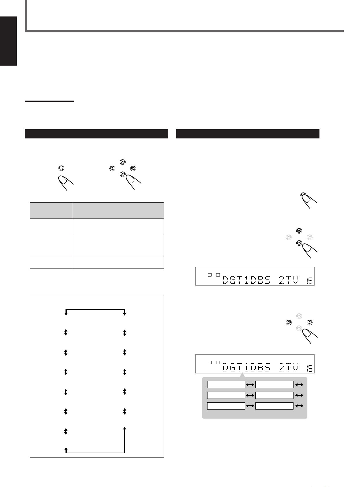
Some of the following settings are required after connecting and positioning your speakers while others will make operations easier.
You can set the items by using the SETTING button and CONTROL 5/∞/2/3 buttons on the front panel.
Setting items:
• Speaker information for front, center, rear speakers, and subwoofer* • Speaker distance for front, center, and rear speakers*
• Crossover frequency* • Low frequency effect attenuator* • Dynamic range compression*
• Digital input (DIGITAL IN) terminals • Auto surround • Video output mode
Note:
*
You can also set these items using the Choice menu (see pages 47 to 52).
Operation Buttons
To do the basic settings for this unit, use the buttons on the front
panel.
On the front panel ONLY
Button
SETTING
CONTROL 5/∞
CONTROL 3/2
• When no operation is done for about 5 seconds, the indications on
the display will disappear.
* Pressing SETTING repeatedly also changes the indication.
Configuration of the indications on the display
To do
Display the setting indications on the
display*.
Select an item on the display.
Each time you press the button, the
indication changes as illustrated below.
Adjust the selected item.
Operating Procedure
Ex. : When setting the digital input (DIGITAL IN) terminals.
Before you start, remember...
There is a time limit in doing the following steps. If the setting is
canceled before you finish, start from step
1
Press SETTING.
The CONTROL buttons now work for basic settings.
The setting item selected previously appears on the
display.
2
Press CONTROL ∞ (or 5)
1
again.
repeatedly until “DGT (Digital)”
(with the current setting)
* appears
on the display.
* “1DBS 2TV” is the initial setting. If you have already changed
the setting, another combination will be shown.
19
3
Press CONTROL 3 (or 2) to select
the appropriate digital terminal
setting.
• Each time you press the button, the indication
changes as follows:
Page 23
7
DIGITAL AUTO
VOLUME
LR
SPK.
DIGITAL AUTO
VOLUME
LR
SPK.
DIGITAL AUTO
VOLUME
LR
SPK.
DIGITAL AUTO
VOLUME
LR
SPK.
DIGITAL AUTO
VOLUME
LR
SPK.
DIGITAL AUTO
VOLUME
LR
SPK.
DIGITAL AUTO
VOLUME
LR
SPK.
8 ft
(2.4 m)
9 ft
(2.7 m)
10 ft
(3.0 m)
11 ft
(3.3 m)
Left front
speaker
Right front
speaker
Right rear
speaker
Subwoofer
Left rear
speaker
Center speaker
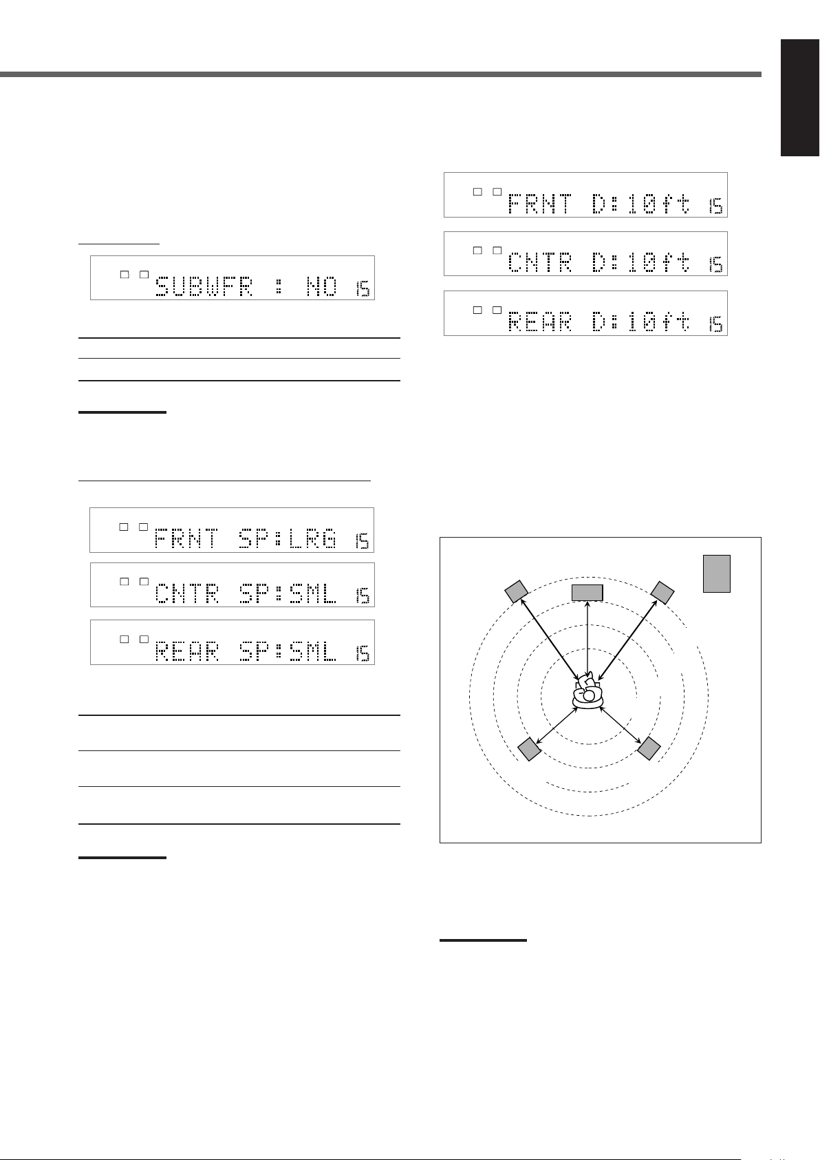
Speaker information—“SUBWFR (subwoofer),”
“FRNT SP (front speaker),” “CNTR SP (center
speaker),” and “REAR SP (speaker)”
To obtain the best possible effect from the Surround modes (see
pages 25 to 28), register the following information after all
connections are completed.
¶ For subwoofer:
Select one of the following settings:
7
Speaker distance—“FRNT D (front distance),”
“CNTR D (center distance),” and “REAR D
(distance)”
English
YES : Select this when a subwoofer is connected.
NO : Select this when no subwoofer is used.
Notes:
•“NO” is the initial setting.
• If you have selected “NO” for the subwoofer, you can only select
“LARGE” for the front speakers.
¶ For front speakers, center speaker, and rear speakers:
Select one of the following settings for each speaker:
LRG (large) : Select this when the speaker size is relatively
large.
SML (small) : Select this when the speaker size is relatively
small.
NO : Select this when you have not connected a
speaker. (Not selectable for the front speakers)
The distance from your listening point to the speakers is another
important element to obtain the best possible surround sound of
the Surround modes.
You need to set the distance from your listening point to the
speakers. By referring to the speaker distance setting, this unit
automatically sets the delay time of the sound through each
speaker so that sounds through all the speakers can reach you at
the same time.
Set the distance from the listening point within the range of
1 ft (0.3 m) to 30 ft (9.0 m), in 1 ft (0.3m) interval.
Notes:
•“LRG (large)” is the initial setting for the front speakers, “SML
(small)” for the center and rear speakers.
• Keep the following comment in mind as reference when
adjusting the settings.
– If the size of the cone speaker unit built in your speaker is
greater than 12 cm (4 3/4 inches), select “LRG (large),” and if
it is smaller than 12 cm (4 3/4 inches), select “SML (small).”
• If you have selected “SML (small)” for the front speakers, you
cannot select “LRG (large)” for the center and rear speakers.
Ex. : In this case,
set “FRNT D” to “11ft (3.3m),”
set “CNTR D” to “10ft (3.0m)” and
set “REAR D” to “9ft (2.7m).”
Notes:
•“10ft” is the initial setting. If you have already changed the
setting, another setting will be shown.
• If you have selected “NO” for the center and rear speakers
setting, you cannot set the speaker distance for the center and
rear speakers.
20
Page 24
Basic Settings
SPK.
DIGITAL AUTO
VOLUME
LR
SPK.
DIGITAL AUTO
VOLUME
DIGITAL
LR
SUBWFR
C
LS RS
SPK.
DIGITAL AUTO
VOLUME
DIGITAL
LFE
LRC
SUBWFR
LS RS
SPK.
DIGITAL AUTO
VOLUME
LR
English
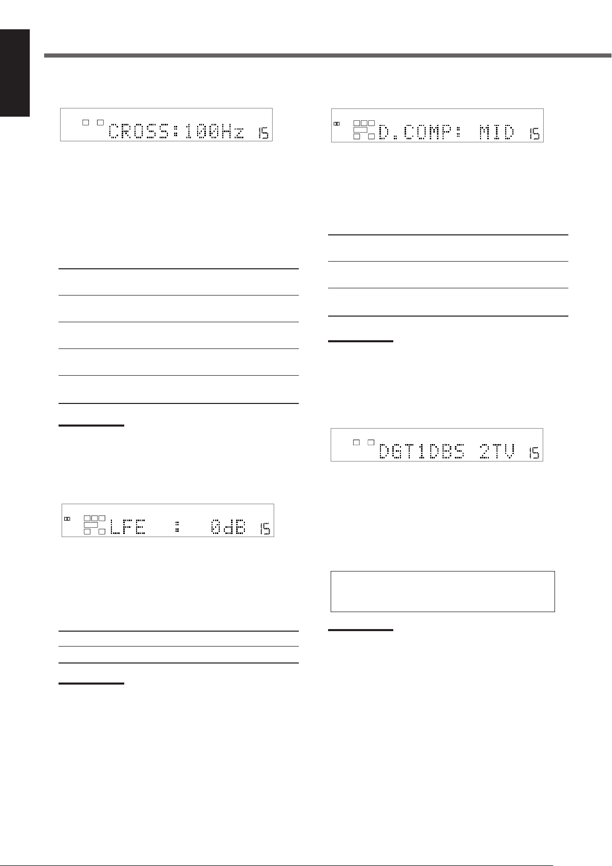
7 Crossover frequency—“CROSS (crossover)”
7 Dynamic range compression—“D.COMP”
Small speakers cannot reproduce the bass sounds efficiently. If
you use a small speaker in any position, this unit automatically
reallocates the bass sound elements assigned to the small
speaker to the large speakers.
To use this function properly, set the crossover frequency level
according to the size of the small speaker connected.
• If you have selected “LRG (large)” for all speakers, this
function will not take effect.
Select one of the following settings:
80Hz : Select this frequency when the cone speaker unit
built in the speaker is about 4 3/4 inches (12 cm).
100Hz : Select this frequency when the cone speaker unit
built in the speaker is about 3 15/16 inches (10 cm).
120Hz : Select this frequency when the cone speaker unit
3
built in the speaker is about 3
/16 inches (8 cm).
150Hz : Select this frequency when the cone speaker unit
built in the speaker is about 2 3/8 inches (6 cm).
200Hz : Select this frequency when the cone speaker unit
built in the speaker is less than 2 inches (5 cm).
Notes:
•“100Hz” is the initial setting. If you have already changed the
setting, another frequency will be shown.
• Crossover frequency is not valid for the HEADPHONE mode.
You can compress the dynamic range (difference between
maximum sound and minimum sound) of the reproduced sound.
This is useful when enjoying surround sound at night.
• This function takes effect only when playing back a source
encoded with Dolby Digital.
Select one of the following settings:
OFF : Select this when you want to enjoy surround with its
full dynamic range. (No effect applied.)
MID : Select this when you want to reduce the dynamic range
a little.
MAX : Select this when you want to apply the compression
effect fully. (Useful at night.)
Note:
•“MID” is the initial setting. If you have already changed the
setting, another setting will be shown.
7 Digital input (DIGITAL IN) terminals—“DGT”
7 Low frequency effect attenuator—“LFE”
If the bass sound is distorted while playing back software
encoded with Dolby Digital or DTS Digital Surround, set the
LFE level to eliminate distortion.
• This function takes effect only when the LFE (subwoofer)
signals come in.
Select one of the following settings:
0dB : Normally select this.
–10dB : Select this when the bass sound is distorted.
Note:
•“0dB” is the initial setting. If you have already changed the
setting, “–10dB” will be shown.
When you use the digital input terminals, register what
components are connected to which terminals (DIGITAL IN 1/
DIGITAL IN 2). So, the correct source name will appear when
you select the digital source.
Set the appropriate digital terminal setting.
• Each time you press CONTROL 3 or 2, the display changes
as follows:
1 DBS 2 TV “ 1 DBS 2 CDR “ 1 TV 2 DBS “
1 TV 2 CDR “ 1 CDR 2 DBS “ 1 CDR 2 TV “
(back to the beginning)
Notes:
•“1DBS 2TV” is the initial setting. If you have already changed
the setting, another combination will be shown.
• If you want to connect a CD recorder to the digital input
terminal, change the source name to “CDR” from “TAPE.”
For details, see “Changing the Source Name” on page 12.
21
Page 25
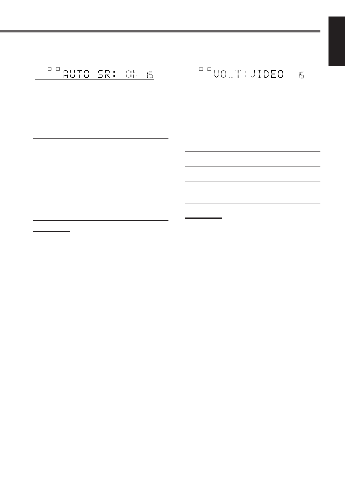
7 Auto surround—“AUTO SR”
SPK.
DIGITAL AUTO
VOLUME
LR
SPK.
DIGITAL AUTO
VOLUME
AUTO
SURROUND
LR
7 Video output mode—“VOUT”
English
Surround mode is automatically activated when the digital
multichannel source such as Dolby Digital or DTS Digital
Surround software or 2-channel matrix source such as Dolby
Surround is played back.
You can enjoy Surround mode simply by selecting the source
(with digital input selected for that source)—Auto Surround.
Select one of the following settings:
ON : The AUTO SURROUND indicator always lights up
on the display.
• If multichannel signals come in, an appropriate
Surround mode will be turned on.
• If Dolby Digital 2-channel or DTS 2-channel
including surround signals come in, “PL II
MOVIE” will be selected.
• If Dolby Digital 2-channel or DTS 2-channel
signals without surround signals come in,
“STEREO” will be selected.
• If the other signals come in, nothing will change.
OFF : Select this to deactivate Auto Surround.
Notes:
•“ON” is the initial setting. If you have already changed the
setting, “OFF” will be shown.
• This function does not take effect in the following cases:
– While playing an analog source.
– While selecting “DGTL D.D.” or “DGTL DTS” as the fixed
digital input mode (see page 13).
• If you press SURROUND ON/OFF (SURR ON/OFF on the
remote control) with Auto Surround activated, Auto Surround
will be canceled temporarily for the currently selected source.
Auto Surround setting will be restored in the following cases:
– When you turn off and on the unit,
– When you change the source,
– When you change the analog/digital input, and
– When you reset “AUTO SR” to “ON” again.
After connecting your TV to the unit, register the type of the
connected output terminal—VIDEO, S-VIDEO, or
DVD COMPONENT VIDEO OUT.
Without setting this, AV COMPU LINK does not work
appropriately when DVD is selected as the source (see
“AV COMPU LINK Remote Control System” on pages 57 and
58).
Set the output terminal appropriately.
VIDEO : Select this when you connect your TV to VIDEO
jack by using a composite video cord.
S : Select this when you connect your TV to S-VIDEO
jack by using an S-video cord.
COMPNT : Select this when you connect your TV to DVD
COMPONENT VIDEO OUT jacks by using
component video cord.
Note:
•“VIDEO” is the initial setting. If you have already changed the
setting, another setting will be shown.
22
Page 26

Sound Adjustments
ADJUST
CONTROL
BAL
(Balance)
BASS
TREBLE
SUBWFR
(Subwoofer)
CENTER
REAR L
(Rear left)
REAR R
(Rear right)
EFFECT
#
#
#
#
#
#
ADJUST
CONTROL
SPK.
DIGITAL AUTO
VOLUME
LR
CONTROL
SPK.
DIGITAL AUTO
VOLUME
LR
CENTERR –21 L –21
English
The following settings are required after connecting and positioning your speakers.
You can adjust the items by using the ADJUST button and CONTROL 5/∞/2/3 buttons on the front panel.
Adjustment items:
• Front speaker output balance* • Tone* • Speaker output levels*
• DAP effect level
Notes:
• The setting contents of adjustment items are memorized for each source.
*
You can also set these items using the Choice menu (see pages 47 to 52).
Operation Buttons
To do the basic settings for this unit, use the buttons on the front
panel.
On the front panel ONLY*
Button
ADJUST
CONTROL 5/∞
CONTROL 3/2
• When no operation is done for about 5 seconds, the indications
on the display will disappear.
* You can also make sound adjustment except for front speakers
output balance from the remote control.
** Pressing ADJUST repeatedly also changes the indication.
Configuration of the indications on the display
To do
display the adjustment indications on
the display**
select an item on the display
Each time you press the button, the
indication changes as illustrated below.
adjust the selected item
Operating Procedure
Ex. : When setting the front speaker output balance.
Before you start, remember...
There is a time limit in doing the following steps. If the setting is
canceled before you finish, start from step
1
Press ADJUST.
1
again.
The CONTROL buttons now work for sound
adjustments. The setting item selected previously
appears on the display.
2
Press CONTROL ∞ (or 5)
repeatedly until “BAL (Balance)”
(with the current setting)
* appears
on the display.
* “CENTER” is the initial setting. If you have already changed
the setting, another setting will be shown.
3
Press CONTROL 3 (or 2) to adjust
the front speaker balance.
• Each time you press the button, the indication
changes as follows:
#
These indications appear only when the corresponding speakers
information for each speaker is set to other than “NO.”
##
“EFFECT” appears only when one of DAP modes (see pages 25
to 28) is activated.
23
Page 27

7 Front speaker output balance
SPK.
DIGITAL AUTO
VOLUME
LR
SPK.
DIGITAL AUTO
VOLUME
LR
SPK.
DIGITAL AUTO
VOLUME
LR
SPK.
DIGITAL AUTO
VOLUME
LR
SUBWFR
SPK.
DIGITAL AUTO
VOLUME
DIGITAL
LFE
LRC
SUBWFR
LS RS
SPK.
DIGITAL AUTO
VOLUME
DIGITAL
LFE
LRC
SUBWFR
LS RS
SPK.
DIGITAL AUTO
VOLUME
DIGITAL
LFE
LRC
SUBWFR
LS RS
SPK.
ANALOG DSP
VOLUME
LR
SUBWFR
LS RS
—“BAL (balance)”
If the sounds you hear from the front right and left speakers are
unequal, you can adjust the speaker output balance.
Adjust the output balance appropriately from the listening
point within the range of R (Right) –21 to CENTER (0) or
CENTER (0) to L (Left) –21.
Note:
•“CENTER” is the initial setting. If you have already changed
the setting, another setting will be shown.
7 Speaker output levels—“SUBWFR
(subwoofer),” “CENTER,” “REAR L (left),”
and “REAR R (right)”
English
7 Tone—“BASS” and “TREBLE”
You can adjust the bass and treble sounds as you like.
Adjust the tone within the range of –10 to +10 in 2 steps
intervals.
Note:
•“0” is the initial setting. If you have already changed the setting,
another setting will be shown.
Adjusting sound from the remote control
1
Press SOUND.
Number buttons now work for sound adjustments.
2
Adjust the level as follows:
To adjust subwoofer, press SUBWOOFER + or –.
To adjust center speaker, press CENTER + or –.
To adjust left rear speaker, press REAR•L + or –.
To adjust right rear speaker, press REAR•R + or –.
To adjust the effect level (for DAP mode), press EFFECT.
You can adjust the speaker output levels if you have set the
speaker information appropriately.
• You can adjust the output level for center and/or rear speakers
only when one of proper Surround modes is activated (see
page 27).
Adjust the speaker output level within the range of –10 to
+10 in 1 step interval.
Note:
•“0” is the initial setting. If you have already changed the setting,
another setting will be shown.
7 DAP effect level—“EFFECT”
While one of DAP modes is activated (the DSP indicator lights
up on the display), you can adjust the effect level.
For details about DAP modes, see pages 25 to 28.
Adjust the effect level within the range of 1 to 5.
Note:
•“3” is the initial setting. If you have already changed the setting,
another setting will be shown.
About auto memory
This unit memorizes the settings for each source:
• when you turn off the power (see page 11),
• when you change the source (see page 11),
• when you change the source name (see page 12), and
• when you change the analog/digital input mode (see page 13).
When you change the source, the memorized settings for the
newly selected source are automatically recalled.
The following can be stored for each source:
• Analog/digital input mode (see page 13)
• Input attenuator mode (see page 14)
• Front speaker output balance (see above or page 50)
• Speaker output level (see above or page 51)
• Tone adjustment (see above or page 50)
• DAP effect level (see above)
• Surround mode selection (see page 27)
Note:
• If the source is FM or AM, you can assign a different setting for
each band.
24
Page 28

Creating Realistic Sound Fields
DOLBY SURROUND
DIGITAL
Subwoofer
Left front
speaker
Right rear
speaker
Left rear
speaker
Center
speaker
Right front
speaker
MASTER VOLUME
DVD/SUPER VCD/VCD/CD
INPUT ATT. REC MODE
INPUT
ANALOG/DIGITAL
COMPACT
SUPER VIDEO
DIGITAL
SURROUND
SETTINGADJUST MEMORY
RX-DV3 HOME THEATER DVD/CD RECEIVER
ON/OFF
SURROUND
MODE
FM/AMTAPE/CDR
SOURCE NAME
TVVCRDBSDVD
CONTROL
STANDBY
STANDBY/ON
English
You can use the following Surround modes to reproduce a realistic
sound field:
■ Dolby Surround
• Dolby Pro Logic II
• Dolby Digital
■ DTS Digital Surround
■ DAP (Digital Acoustic Processor) modes
■ All Channel Stereo
■ Dolby Surround
Dolby Pro Logic II*
Dolby Pro Logic II has newly developed multichannel playback
format to decode into 5.1-channel from all 2-channel sources—
stereo source and Dolby Digital encoded source.
Matrix-based encoding/decoding method for Dolby Pro Logic II
makes no limitation for the cutoff frequency of the rear treble and
enables stereo rear sound compared to conventional Dolby Pro
Logic.
Dolby Pro Logic II enables to reproduce spacious sound from
original sound without adding any new sounds and tonal colorations.
Dolby Pro Logic II has two modes—Movie mode and Music mode:
Pro Logic II Movie (PL II MOVIE)—suitable for reproduction of
Dolby Surround encoded sources bearing the mark
and stereo television sources. You can enjoy sound field very close
to the one created with discrete 5.1-channel sounds.
Pro Logic II Music (PL II MUSIC)—suitable for reproduction of
any 2-channel stereo music sources. You can enjoy wide and deep
sound by using this mode.
• When Dolby Pro Logic II is activated, the PRO LOGIC II
indicator lights up on the display.
Dolby Digital*
Used to reproduce multichannel sound tracks of the software
encoded with Dolby Digital (
• To enjoy the software encoded with Dolby Digital, connect the
source component using the digital terminal on the rear of this
unit. (See page 10.)
Dolby Digital 5.1-channel encoding method (so-called discrete
multichannel digital audio format) records and digitally compresses
the left front channel, right front channel, center channel, left rear
channel, right rear channel, and LFE channel signals.
Since each channel is completely independent from the other
channel signals to avoid interference, you can obtain much better
sound quality with much stereo and surround effects.
).
■ DTS Digital Surround**
Used to reproduce multichannel sound tracks of the software
encoded with DTS Digital Surround ( ).
• To enjoy the software encoded with DTS Digital Surround,
connect the source component using the digital terminal on the
rear of this unit. (See page 10.)
DTS Digital Surround is another discrete multichannel digital
audio format available on CD, LD, and DVD software.
Compared to Dolby Digital, audio compression ratio is relatively
low. This fact allows DTS Digital Surround format to add breadth
and depth to the reproduced sounds. As a result, DTS Digital
Surround features natural, solid and clear sound.
Typical Multichannel (5.1-channel) reproduction
■ DAP (Digital Acoustic Processor) modes
DAP modes have been designed to create important acoustic
surround elements.
The sound heard in a live club, dance club, hall or pavilion consists
of direct sound and indirect sound—early reflections and reflections
from behind. Direct sounds reach the listener directly without any
reflection. On the other hand, indirect sounds are delayed by the
distances of the ceiling and walls (see the diagram below).
These indirect sounds are important elements of the acoustic
surround effects. The DAP mode can reproduce a realistic sound
field by adding these indirect sounds.
DAP modes can be used when the front and rear speakers are
connected to this unit (without respect to the center speaker
connection: no sound comes out of the center speaker even if it is
connected).
Note:
• Dolby Digital or DTS software can be roughly grouped into two
categories
—multichannel (up to 5.1-channel) and 2-channel software. To
enjoy surround sounds while playing Dolby Digital 2-channel or
DTS software, you can use Dolby Pro Logic II.
*
Manufactured under license from Dolby Laboratories. “Dolby,” “Pro
Logic,” and the double-D symbol are trademarks of Dolby
Laboratories.
25
**
Manufactured underlicense from Digital Theater Systems, Inc. US
PAT. No. 5,451,942 and other world-wide patents issued and
pending. “DTS” and “DTS Digital Surround” are trademarks of
Digital Theater Systems, Inc. Copyright 1996 Digital Theater
Systems, Inc. All rights reserved.
Page 29

The following DAP modes are provided for this unit:
LIVE CLUB : Gives the feeling of a live music club with a low
ceiling.
DANCE CLUB : Gives a throbbing bass beat.
HALL : Gives clear vocal and the feeling of a concert
hall.
PAVILION : Gives the spacious feeling of a pavilion with a
high ceiling.
These DAP modes can be used to add the acoustic surround effects
while reproducing 2-channel stereo software, either analog or Linear
PCM digital signal, and can give you a real “being there” feeling.
• When one of the DAP modes is selected, the DSP indicator lights
up on the display.
Creating sound field
Reflections from behind
Early reflections
■ All Channel Stereo
This mode can reproduce a larger stereo sound field using all the
connected (and activated) speakers.
All Channel Stereo can be used when the front and rear
speakers are connected to this receiver without respect to the
center speaker connection.
If the center speaker is connected and activated, the same phases of
the front left and right signals are mixed and output through the
center speaker.
All Channel Stereo can be used while reproducing 2-channel stereo
software, either analog or Linear PCM digital signal.
• When All Channel Stereo is selected, the DSP indicator lights up
on the display.
All Channel Stereo reproduction
English
Sound reproduced from normal stereo
Direct sounds
Sound reproduced from All Channel Stereo
Available Surround modes for each input signal
Modes
Signals DIGITAL SURROUND MOVIE MUSIC CLUB CLUB ST.
Dolby Digital
(Multichannel)
Dolby Digital
(2-channel)
Dolby Surround
(matrix 2-ch)
DTS Digital
Surround 䡬⳯䡬⳯⳯⳯⳯⳯⳯⳯
(Multichannel)
DTS Digital
Surround 䡬⳯⳯䡬䡬 ⳯⳯⳯⳯⳯
(2-channel)
Linear PCM 䡬⳯⳯䡬䡬䡬䡬䡬䡬䡬
Analog 䡬⳯⳯䡬䡬䡬䡬䡬䡬䡬
STEREO
䡬 䡬⳯⳯⳯⳯⳯⳯⳯⳯
䡬⳯⳯ 䡬 䡬 ⳯⳯⳯⳯⳯
䡬⳯⳯ 䡬 䡬 ⳯⳯⳯⳯⳯
DOLBY DTS PL II PL II LIVE DANCE
䡬: Possible ⳯: Impossible
HALL PAVILION
ALL CH
26
Page 30

Creating Realistic Sound Fields
ON/OFF
SURROUND
MODE
REC MODE
DIGITAL AUTO
VOLUME
SURROUND
PRO LOGIC
LR
SUBWFR
PL II MOVIE PL II MUSIC
LIVE CLUB
HALL PAVILION
ALL CH ST.
DANCE CLUB
(back to the beginning)
ON/OFF
SURROUND
MODE
REC MODE
SOUND
10/0
SURR MODE
SOUND
7
SURR ON/OFF
DIGITAL AUTO
AUTO
SURROUND
PRO LOGIC
LR
SUBWFR
DIGITAL AUTO
SURROUND
PRO LOGIC
LR
SUBWFR
DIGITAL AUTO
VOLUME
SURROUND
PRO LOGIC
LR
SUBWFR
PL II MOVIE PL II MUSIC
English
Activating Surround Mode
Selecting Surround Modes
When Auto Surround is set to “OFF” or 2-channel source other than
Dolby Surround software is played back, activate Surround mode
manually.
Make sure that you have set the speakers information correctly
(see page 20 or 51).
• If only front speakers are connected, you cannot activate any
Surround mode.
On the front panel:
Press SURROUND ON/OFF.
The SURROUND indicator lights up on the display
(when Auto Surround is set to “OFF”).
• Each time you press the button, Surround mode is
activated and deactivated alternately.
From the remote control:
1
Press SOUND.
Number buttons now work for sound adjustments.
2
Press SURR ON/OFF.
The SURROUND indicator lights up on the
display (when Auto Surround is set to “OFF”).
• Each time you press the button, Surround mode
is activated and deactivated alternately.
When 2-channel source is played back with Surround mode
activated, you can select another Surround mode.
Available Surround modes will vary depending on the number of the
connected speakers and the playback sound.
Make sure that you have set the speaker information correctly
(see page 20 or 51).
• If rear speakers are not connected, you cannot use DAP modes
and the All Channel Stereo.
On the front panel:
Press SURROUND MODE.
• Each time you press the button, Surround mode
is changed as illustrated below:
From the remote control:
1
Press SOUND.
Number buttons now work for sound adjustments.
2
Press SURR MODE.
• Each time you press the button, Surround mode is
changed as illustrated below:
When 5 or 4 (except center speaker) speakers are connected:
About SURROUND indicators
• When Auto Surround is set to
“ON,” the AUTO SURROUND
indicator always lights up on the
display.
• When you activate Surround
mode manually with Auto
Surround set to “OFF,” the
SURROUND indicator lights up
on the display.
Signal and speaker indicators on the display
The following signal indicators light up —:
L, R : •When digital input is selected: Light up when
the signals corresponding to each channel come
in.
• When analog input is selected: Always light
C, LS, RS : Light up when the signals corresponding to each
S:Lights up when the monaural rear channel signal
LFE : Lights up when the LFE channel signal comes
27
up.
channel come in.
or Dolby Surround encoded signal comes in.
in.
When 3 (except rear speakers) speakers are connected or
Dolby Digital including matrix source is played back:
Signal indicators Speaker indicators
The speaker indicators light up as follows:
• The subwoofer speaker indicator ( ) lights up when
“SUBWFR” is set to “YES” (see page 20) or “USE” (see
page 51).
• The other speaker indicators light up only when the
corresponding speaker is activated, and also when required
for the current playback.
Page 31

Adjusting Surround Mode
231
564
89
7
VFP
10/0 +10
100+ TV RETURN
EFFECT
– TV/DBS CH +
ANALOG
/DIGITAL
TEST
AUDIO
INPUT
SUBTITLE
SURR ON/OFF
SURR MODE
–
SUBWOOFER
+
SOUND
CENTER
REAR·L
REAR·R
PROGRESSIVE
(
Left front speaker
)
(
Left rear speaker
)(
Right rear speaker
)
(
Center speaker
)(
Right front speaker
)
Using Remote Control
When playing back the source with Surround mode, you can adjust
the speaker output levels for Surround modes.
Once you have adjusted the Surround modes, the adjustment is
memorized for each source.
• You can also adjust Surround modes using the Choice menu (see
pages 47 to 52) or buttons on the front panel (see page 24).
• When using test tone, you can adjust the speaker output levels
without playback sounds.
Notes:
• You can adjust the speaker output levels for the
activated speakers ONLY (the speaker indicators are
lit on the display).
*
You cannot adjust the output levels of center speaker
when one of DAP modes is activated.
**
You can adjust the effect level only when one of DAP
modes is activated.
• Before operating the DVD player using remote
control, press DVD to change the remote control
operation mode to DVD.
English
1
Select and play back software you like.
2
Activate and select Surround mode.
• When 2-channel source is played back, you can select
Surround modes.
3
Adjust the sound.
1) Press SOUND.
Number buttons now work for the sound adjustment.
2) Adjust the speaker output levels as follows:
To adjust center speaker, press CENTER +/–.*
To adjust left rear speaker, press REAR•L +/–.
To adjust right rear speaker, press REAR•R +/–.
To adjust subwoofer, press SUBWOOFER +/–.
To adjust the effect level, press EFFECT.**
The name for the item currently adjusted appears on the
display. For details, see the illustrations of “Speaker output
levels” on page 24.
For using test tone
1) Press SOUND.
2) Press TEST.
The playback sound stops during playback.
“TEST L” starts flashing on the display and a test tone comes
out of the speakers in the following order:
3) Adjust the speaker output level as follows:
To adjust center speaker, press CENTER +/–.
To adjust left rear speaker, press REAR•L +/–.
To adjust right rear speaker, press REAR•R +/–.
Notes:
• You cannot adjust the speaker output levels if you have set the
speaker information to “NO.”
• No test tone comes out of the speaker when its speaker
information is set to “NO.”
• When you press EFFECT or SUBWOOFER +/–, the test tone
stops.
4) Press TEST to stop the test tone.
The test tone stops.
• When no operation is done, the test tone stops automatically
in about 1 minute.
Relation between Surround modes and adjustable items
䡬: Possible ⳯: Impossible
Mode
Item
Dolby Digital 䡬䡬䡬䡬䡬⳯
DTS Digital Surround 䡬䡬䡬䡬䡬⳯
Dolby Pro Logic II 䡬䡬䡬䡬䡬⳯
DAP 䡬⳯䡬䡬䡬䡬
All Channel Stereo 䡬䡬䡬䡬䡬⳯
Note:
• You cannot adjust the speakers which are not used by the selected Surround mode.
TEST CENTER REAR•L REAR•R SUBWOOFER EFFECT
28
Page 32

DVD Player Operations
COMPACT
DIGITAL AUDIO
English
Disc Information
7 Playable Disc Types
This unit has been designed to play back the following discs:
DVD VIDEO, Video CD (VCD), Super Video CD (SVCD), audio CD, CD-R, and CD-RW.
• This unit can also play back MP3 and JPEG files recorded on CD-R and CD-RW. For details about MP3, see “MP3 Disc Playback” on
pages 43 and 44 and about JPEG, see “JPEG Disc Playback” on pages 45 and 46.
• This instruction refers to Video CD as VCD, Super Video CD as SVCD, and audio CD as CD.
Discs you can play:
Disc Type
Mark (Logo)
• The following discs cannot be played back:
DVD AUDIO, DVD-ROM, DVD-RAM, DVD-RW, CD-ROM, CD-I (CD-I Ready), Photo CD, etc.
Playing back these discs will generate noise and damage the speakers.
• On some DVD VIDEO, VCD, or SVCD, their actual operations may be different from what is explained in this manual. This is due to the
disc programming and disc structure, but not a malfunction of this unit.
DVD VIDEO VCD SVCD CD CD-R CD-RW
Note on Region Code
DVD players and DVD VIDEO have their own Region Code
numbers. This unit can play back only DVD VIDEO recorded
with the color system of NTSC whose Region Code numbers
include “1.”
Ex. :
If a DVD VIDEO with the wrong Region Code numbers is
loaded, “REGION CODE ERROR!” appears on the TV and
playback cannot start.
IMPORTANT : Before playing a disc, make sure of the
following...
• Check the connection with the TV.
• Turn on the TV and select the correct input mode on the TV to
view the pictures or on-screen indications on the TV screen.
• For disc playback, you can change the initial setting to your
preference. (See pages 47 to 55.)
” appears on the TV screen when you press a button,
If “
the disc cannot accept an operation you have tried to do, or
data required for that operation is not recorded on the disc.
NOTICE : In some cases, without showing “
will not be accepted.
”, operations
Notes on CD-R and CD-RW
• User-edited CD-R (Recordable) and CD-RW (ReWritable) can
be played back only if they are already “finalized.”
• The unit can play back CD-R or CD-RW recorded on a
personal computer if they have been recorded in the audio CD
format.
The unit can also play back CD-R or CD-RW if MP3 files or
JPEG files are recorded on them.
However, they may not be played back because of their disc
characteristics, recording conditions, or damage or stain on
them. Especially, the configuration and characteristics of an
MP3 disc or a JPEG disc is determined by the writing
(encoding) software and hardware used for recording.
Therefore, due to the software and hardware used, the
following symptoms may occur:
– Some discs may not be played back.
– Some tracks on an MP3 disc are skipped and may not be
played back normally.
– Some files on a JPEG disc may be played back distortedly.
• Before playing back CD-R or CD-RW, read their instructions
or cautions carefully.
• CD-RW may require a longer readout time. It is caused by the
fact that the reflectance of CD-RW is lower than for regular
audio CD.
29
Page 33

7 Disc structure
DVD VIDEO consists of “titles,” and each title may be divided into
some “chapters” (see Example 1).
For example, if DVD VIDEO contains some movies, each movie
may have its own title number and it may be further divided into
some chapters. In DVD VIDEO Karaoke, each song may have its
own title number, but it may not be further divided into chapters.
VCD, SVCD, and CD consist of “tracks” (see Example 2).
In general, each track has its own track number. (On some discs,
each track may also be divided by Indexes. This unit is not
compatible with Index function.)
7 Playback Control function (PBC)
The Playback Control function allows you to enjoy menu-driven
operation.
Menu-driven playback
A selection menu is displayed when you start playing VCD and
SVCD with the Playback Control feature. The selection menu shows
a list of numbers for selection. Some discs may show moving
pictures or a divided screen.
You can interact with the screen using a menu display to select and
play an entry.
See the example illustration on the right about basic feature of
menu-driven playback (for details about the operation through the
menu, see also page 33).
English
Example 1: DVD VIDEO
Example 2 : VCD/SVCD/CD
Note:
• While operating VCD or SVCD using the menu, some of the
functions such as repeat play may not work.
30
Page 34

AUDIO
CD
SUPER
VCD
VIDEO
CD
DVD
VIDEO
DVD Player Operations
TIME
OFF
CHAP.
1/3
1/3
1/3
PROG.
RND.
CHOICE
ENTER
ON SCREEN
DIGEST TOP MENU MENU
RETURN
8.5Mbps
DVD-VIDEO
TITLE
14
TOTAL
1:25:58
CHAP
23
8.5Mbps
DVD-VIDEO
TITLE
14
TOTAL
1:25:58
CHAP
23
8.5Mbps
TITLE
14
TOTAL
1:25:58
CHAP
23
OFF
1/3
1/3 1/3
TIME
CHAP.
DVD-VIDEO
8.5Mbps
TITLE
14
TOTAL
1:25:58
CHAP
23
OFF
1/3
1/3 1/3
TIME
CHAP.
DVD-VIDEO
23
4
1
TITLE
14
CHAP
23
TRACK
14
TOTAL
1:25:58
English
This section explains advanced operations of the built-in DVD player using the remote control. For MP3 playback, see pages 43 and 44, and
for JPEG playback, see pages 45 and 46.
Before using the remote control, press DVD to change the remote control operation mode.
• See also “Basic DVD Player Operations” on pages 15 and 16.
•
• Turn on your TV and select the correct input mode on the TV.
If “
that operation is not recorded on the disc.
Using the On-screen Bar
You can check the information of a disc while the disc is loaded and
use some functions through the on-screen bar.
show which types of disc are available for the operation.
” appears on the TV when you press a button, the disc cannot accept an operation you have tried to do, or data required for
Ex. : When a DVD VIDEO is played
& Whenever a disc is loaded
Press ON SCREEN.
• Each time you press the button, the on-screen bar changes as
shown to the right:
1 Disc type
2 Playback information
3 Playback conditions for all types of disc
31
Contents of the on-screen bar with the pull-down menu
Ex.: When a DVD VIDEO is played
Indications Meanings Available discs
Mbps shows the current
transfer rate (Megabits
per second).
shows the current title.
shows the current
chapter.
shows the current
track.
shows the elapsed
playing time.
Indications Meanings
Playback
/ Fast forward/Fast reverse
/ Forward/reverse slow-motion
Pause
Stop
All discs
(with the pull-down menu)
The on-screen bar disappears.
(back to the beginning)
4 Operation icons (on the pull-down menu)
Indications
Meanings Available discs
Select this to change the
time indication.
See page 32.
Select this to repeat
playback. See page 42.
Select this for time search.
See page 37.
Select this for chapter
search. See page 37.
Select this to change the
audio language or channel.
See pages 35 and 36.
Select this to change
subtitle language.
See page 35.
Select this to change the
view angle. See page 34.
Select this for the program
play. See page 41.
Select this for the random
play. See page 41.
All discs
Page 35

Basic Operation through the On-screen
OFF
CHOICE
ENTER
ON SCREEN
DIGEST TOP MENU MENU
RETURN
8.5Mbps
DVD-VIDEO
TITLE
14
TOTAL
1:25:58
CHAP
23
OFF
1/3
1/3 1/3
TIME
CHAP.
CHOICE
ENTER
ON SCREEN
DIGEST TOP MENU MENU
RETURN
TIME
TOTAL
1:25:58
T.REM
0:45:41
TIME
0:25:58
REM
0:18:14
8.5Mbps
DVD-VIDEO
TITLE
14
TOTAL
1:25:58
CHAP
23
OFF
1/3
1/3 1/3
TIME
CHAP.
8.5Mbps
DVD-VIDEO
TITLE
14
TOTAL
1:25:58
CHAP
23
OFF
1/3
1/3 1/3
TIME
CHAP.
OFF
8.5Mbps
DVD-VIDEO
TITLE
14
TOTAL
1:25:58
CHAP
23
OFF
1/3
1/3 1/3
TIME
CHAP.
TITLE
8.5Mbps
DVD-VIDEO
TITLE
14
TOTAL
1:25:58
CHAP
23
TITLE
1/3
1/3 1/3
TIME
CHAP.
Bar
Ex. : When selecting the repeat mode for DVD VIDEO
Changing the Time Indication
You can change the time information in the on-screen bar and the
display window on the center unit.
English
& During playback or while
stopped
1
Press ON SCREEN twice.
The on-screen bar with pull-down menu appears on the TV.
2
Press cursor 3 (or 2) repeatedly to move to
on the pull-down menu.
3
Press ENTER.
The pop-up window appears under the pull-down menu.
4
Press cursor ∞ (or 5) to select the desired option
in the pop-up window.
• Each time you press the button, the options change.
5
Press ENTER.
The setting changes and the pop-up window goes off.
& During playback or while
stopped
1
Press ON SCREEN twice.
The on-screen bar appears on the TV.
2
Press cursor 3 (or 2) to move to
3
Press ENTER.
.
• Each time you press the button, the time indication changes as
follows:
TOTAL ] T. (total) REM ] TIME ] REM ]
(back to the beginning)
TOTAL : Elapsed time of the disc
T. REM : Remaining time of the disc
TIME : Elapsed playing time of the current chapter/track
REM : Remaining time of the current chapter/track
To turn off the on-screen bar
Press ON SCREEN.
Notes:
• The time indication in the on-screen bar changes as follows:
EX. :
]
]
]
] (back to the beginning)
The indication on the display also changes.
• While playing VCD, SVCD, or CD, the indication of the hour digit
does not appear.
To turn off the on-screen bar
Press ON SCREEN.
Note:
• See the pages for the detail of each function.
32
Page 36
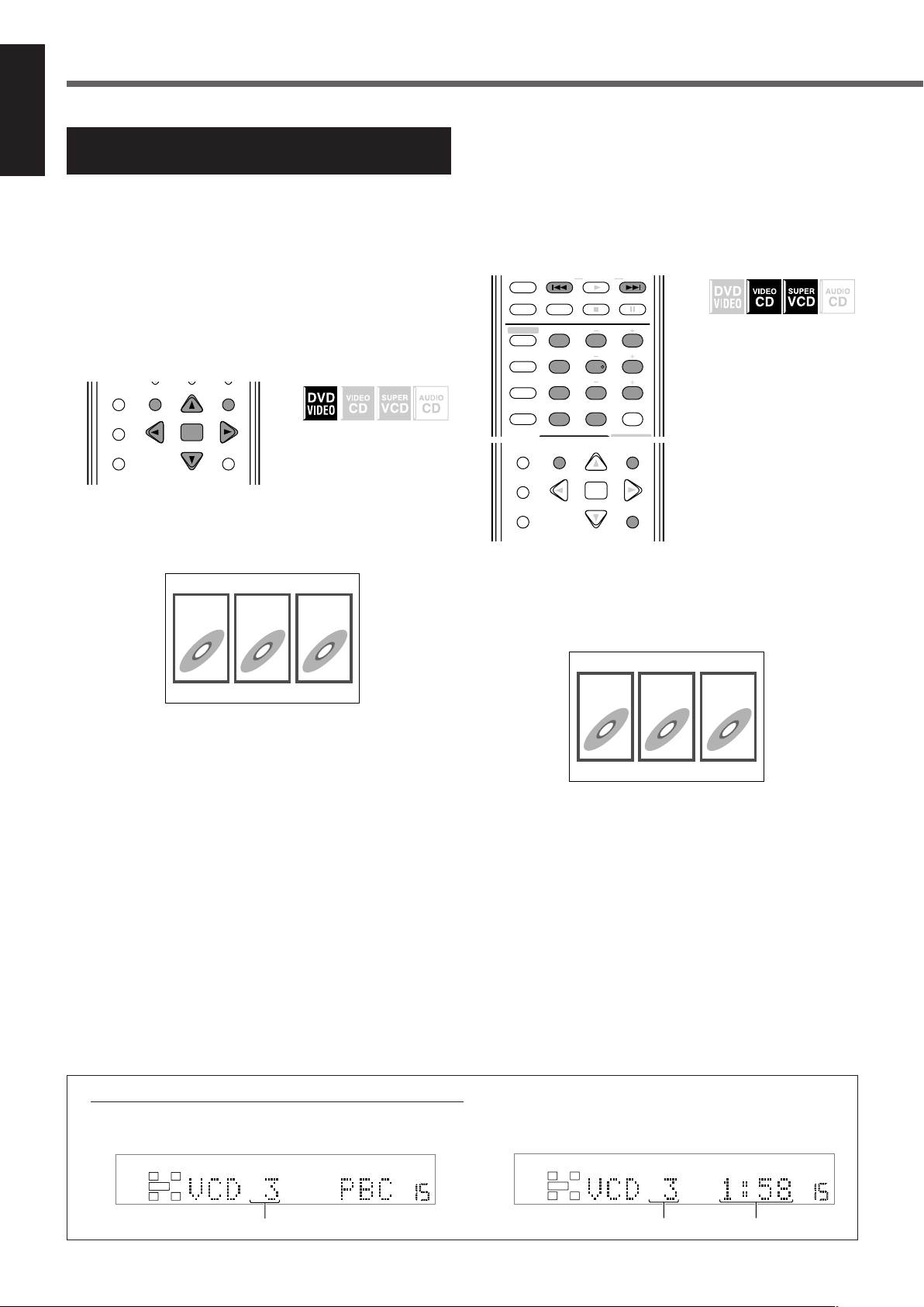
DVD Player Operations
CHOICE
ENTER
ON SCREEN
DIGEST TOP MENU MENU
RETURN
SPK.
DIGITAL AUTO DSP
VOLUME
LR
SUBWFR
SPK.
DIGITAL AUTO DSP
VOLUME
LR
SUBWFR
1
23
VFP
231
564
89
7
10/0 +10
100+ TV RETURN
TV/VIDEO REW/(TUNING
9
/FF
REPEAT SLEEP FM MODE STROBE
EFFECT
– TV/DBS CH +
ANALOG
/DIGITAL
TEST
AUDIO
INPUT
SUBTITLE
SURR ON/OFF
SURR MODE
–
SUBWOOFER
+
SOUND
CENTER
REAR·L
REAR·R
CHOICE
ON SCREEN
DIGEST
ENTER
TOP MENU MENU
RETURN
1
23
English
Locating a Desired Scene from
the Disc Menu
Using the disc menu, you can start playing a title, chapter, or track
you specify.
If the on-screen bar is shown on the TV, press ON SCREEN
repeatedly to go off the on-screen bar.
7 From the DVD menu
DVD VIDEO generally have their own menus which show the disc
contents. These menus contain various items such as titles of
movies, names of songs, or artist information, and display them on
the TV screen. You can locate a desired scene by using these menus.
& When DVD VIDEO is
loaded
1
Press TOP MENU or MENU.
The DVD menu appears on the TV. (The menu usually appears
on the TV automatically after loading DVD VIDEO.)
Ex. :
7 From the VCD/SVCD menu with PBC
VCD or SVCD recorded with PBC has its own menus such as a list
of the tracks. (After loading such a disc, “PBC” appears on the
display.) You can locate the specific track by using the menu (see
also page 30).
• Before using the remote control, press DVD to change the
remote control operation mode.
& When the menu appears on
the TV during playback
with PBC
Press number buttons (1–10, +10) to select the
number of the desired item.
The unit starts playback from the selected item.
Ex. : To select 3, press 3.
To select 11, press +10, then 1.
DVD VIDEO normally has a “title” menu when it contains more
than one title. In this case, press TOP MENU to show the title
menu.
Some DVD VIDEO may also have a different menu which is
shown by pressing the MENU button.
See the instructions of each DVD VIDEO for its particular
menu.
2
Use cursor 5/∞/3/2 to select a desired item,
then press ENTER.
The unit starts playback of the selected item.
• With some discs, you can also select items by entering the
corresponding number using number buttons.
About indication on the display while playing back a VCD/SVCD
While you are playing back a VCD/SVCD recorded with PBC, playback information appears on the display as follows:
Ex. : When VCD is played back using PBC Ex. : When VCD is played back without using PBC
33
Ex. :
To return to the menu
Press RETURN.
When “NEXT” or “PREVIOUS” is shown on the TV screen:
To go to the next page, press ¢.
To return to the previous page, press 4.
To play back PBC-compatible VCD/SVCD without PBC
Start playback by pressing the number buttons while playback is
stopped.
The elapsed playing time appears on the display instead of “PBC.”
To restore PBC
Press TOP MENU or MENU.
“PBC” appears again on the display.
Track number
Track number Elapsed playing time
Page 37
Selecting a View Angle—ANGLE
+–+
–
100+ TV RETURN
CHOICE
ON SCREEN
ANGLE
ZOOM
DIGEST
ENTER
TOP MENU MENU
RETURN
DIMMER
MUTING
TV VOL VOLUME
PROGRESSIVE
+–+
–
VFP
10/0 +10
100+ TV RETURN
SUBTITLE
ANGLE
ZOOM
SURR MODE
DIMMER
MUTING
TV VOL VOLUME
–
SUBWOOFER
+
PROGRESSIVE
1
1
1/3
1/3
1
1/3
2
2/3
3
3/3
8.5Mbps
DVD-VIDEO
TITLE
14
TOTAL
1:25:58
CHAP
23
OFF
1/3
1/3 1/3
TIME
CHAP.
1
While playing back DVD VIDEO containing multi-view angles, you
can enjoy the same scene at different angles.
The
icon appears at the beginning of playback when the current
scene has multi-view angles.
7 Selecting a view angle
& During playback
3
Press cursor ∞ (or 5) repeatedly to select the
desired view angle.
• Each time you press the button, the angle of the scene
changes.
4
Press ENTER.
The pop-up window goes off.
To turn off the on-screen bar
Press ON SCREEN.
English
1
Press ANGLE.
The following pop-up window appears on the TV.
Ex. : The first view angle is selected out of 3 view angles
recorded.
2
Press ANGLE repeatedly to select the desired
view angle.
• Each time you press the button, the angle of the scene
changes.
Ex.: 1/3 ] 2/3 ] 3/3 ] (back to the beginning)
The pop-up window goes off if no operation is done for about
5 seconds.
7 Showing all view angles on the TV
& During playback
1
Press and hold ANGLE for a few seconds.
Up to 9 pictures of the different camera angles recorded on a
disc appear on the TV screen.
Ex. : When 3 view angles are recorded.
Angle list
Selected picture
Using the on-screen bar:
1
Press ON SCREEN repeatedly until the on-screen
bar with pull-down menu appears on the TV.
2
Press cursor 3 (or 2) repeatedly to move to
in the pull-down menu, then press
ENTER.
The following pop-up window appears under the pull-down
menu.
Ex. : The first view angle is selected out of 3 view angles
recorded.
2
Press cursor 5/∞/3/2 repeatedly to move to
the desired view.
3
Press ENTER.
The angle list goes off, and playback starts at the selected view
angle.
Notes:
• While the angle list is shown on the TV, you cannot listen to the
sound.
• If “ ” appears on the TV, the current scene does not contain
multi-view angles.
34
Page 38
DVD Player Operations
+ +
564
89
7
VFP
10/0 +10
100+ TV RETURN
AUDIO
SUBTITLE
ANGLE
SURR ON/OFF
SURR MODE
DIMMER
–
SUBWOOFER
+
REAR·R
PROGRESSIVE
ENGLISH
ENGLISH
1/3
1/3
564
89
7
VFP
10/0 +10
100+ TV RETURN
/DIGITAL
TEST
AUDIO
INPUT
SUBTITLE
SURR ON/OFF
SURR MODE
–
SUBWOOFER
+
REAR·L
REAR·R
PROGRESSIVE
8.5Mbps
DVD-VIDEO
TITLE
14
TOTAL
1:25:58
CHAP
23
OFF
1/3
1/3 1/3
TIME
CHAP.
ENGLISH
8.5Mbps
DVD-VIDEO
TITLE
14
TOTAL
1:25:58
CHAP
23
OFF
1/3
1/3 1/3
TIME
CHAP.
ENGLISH
ENGLISH
ENGLISH
1/3
1/3
English
Changing the Languages—SUBTITLE and
AUDIO
While playing back DVD VIDEO or SVCD containing subtitles in
different languages, you can select the subtitle language to be
displayed on the TV.
The
icon appears at the beginning of playback when the current
scene has plural subtitles.
When DVD VIDEO contains audio languages (soundtrack), you can
select the language (soundtrack) to listen to.
The
icon appears at the beginning of playback when the current
scene has plural audio languages.
• You can also select the audio channel(s) of VCD or SVCD.
7 Selecting the subtitle language
& During playback
1
Press SUBTITLE.
The following pop-up window appears on the TV.
Ex. : “ENGLISH” is selected among 3 subtitle languages
recorded.
4
Press ENTER.
The pop-up window goes off.
To turn off the on-screen bar
Press ON SCREEN.
Notes:
• For DVD VIDEO: Some subtitle languages are abbreviated in the
pop-up window. See “Language code list” on page 50.
• For SVCD: SVCD can contain up to four subtitles. Pressing
SUBTITLE changes the subtitles regardless of whether the
subtitles are recorded or not. (Subtitles will not change if no subtitle
is recorded.)
• If “ ” appears on the TV, the current scene does not contain
plural subtitles.
7 Selecting the audio language
& During playback
1
Press AUDIO.
The following pop-up window appears on the TV.
Ex. : “ENGLISH” is selected among 3 audio languages
recorded.
2
Press SUBTITLE repeatedly to select the desired
subtitle language.
• Each time you press the button, the subtitle language changes.
The pop-up window goes off if no operation is done for about
5 seconds.
Using the on-screen bar:
1
Press ON SCREEN repeatedly until the on-screen
bar with pull-down menu appears on the TV.
2
Press cursor 3 (or 2) repeatedly to move to
in the pull-down menu, then press
ENTER.
The following pop-up window appears under the pull-down
menu.
Ex. : “ENGLISH” is selected among 3 subtitle languages
recorded.
3
Press cursor ∞ (or 5) repeatedly to select the
desired subtitle language.
• Each time you press the button, the subtitle language changes.
35
2
Press AUDIO repeatedly to select the desired
audio language.
• Each time you press the button, the audio language changes.
The pop-up window goes off if no operation is done for about
5 seconds.
Using the on-screen bar:
1
Press ON SCREEN repeatedly until the on-screen
bar with pull-down menu appears on the TV.
2
Press cursor 3 (or 2) repeatedly to move to
in the pull-down menu, then press
ENTER.
The following pop-up window appears under the pull-down
menu.
Ex. : “ENGLISH” is selected among 3 audio languages
recorded.
Page 39
3
+–+
–
231
564
89
7
VFP
10/0 +10
100+ TV RETURN
EFFECT
ANALOG
/DIGITAL
TEST
AUDIO
INPUT
SUBTITLE
CHOICE
ENTER
ON SCREEN
ANGLE
ZOOM
DIGEST TOP MENU MENU
RETURN
SURR ON/OFF
SURR MODE
DIMMER
MUTING
TV VOL VOLUME
–
SUBWOOFER
+
SOUND
CENTER
REAR·L
REAR·R
PROGRESSIVE
ST
ST
ST
ST
VCD
TRACK
4
TIME
25:58
OFF
ST
TIME
ST
PROG.
Press cursor ∞ (or 5) repeatedly to select the
desired audio language.
• Each time you press the button, the audio language changes.
2
Press AUDIO repeatedly to select the desired
audio channel.
• Each time you press the button, the audio channel changes.
English
4
Press ENTER.
The pop-up window goes off.
To turn off the on-screen bar
Press ON SCREEN.
Notes:
• Some audio languages are abbreviated in the pop-up window. See
“Language code list” on page 50.
• If “ ” appears on the TV, the current scene does not contain
plural audio languages.
7 Selecting the audio channel
When playing back some Karaoke VCDs or SVCDs, you can enjoy
Karaoke by selecting the audio channel to play.
& During playback
For VCD :
Ex. :
ST ] L ] R ] (back to the beginning)
ST : To listen to normal stereo playback.
L:To listen to the L (left) audio channel.
R:To listen to the R (right) audio channel.
For SVCD :
Ex. :
ST 1 ] ST 2 ] L 1 ] R 1 ] L 2 ] R 2 ]
(back to the beginning)
ST 1/ST 2 : To listen to normal stereo playback of ST 1 or
ST 2 channel.
L 1/L 2 : To listen to the L (left) 1 or 2 audio channel.
R 1/R 2 : To listen to the R (right) 1 or 2 audio channel.
The pop-up window goes off if no operation is done for about 5
seconds.
Using the on-screen bar:
1
Press ON SCREEN repeatedly until the on-screen
bar with pull-down menu appears on the TV.
1
Press AUDIO.
The following pop-up window appears on the TV.
Ex. : When VCD is loaded.
2
Press cursor 3 (or 2) repeatedly to move to
in the pull-down menu, then press
ENTER.
The following pop-up window appears under the pull-down
menu.
Ex. : When VCD is loaded.
3
Press cursor ∞ (or 5) repeatedly to select the
desired audio channel(s).
• Each time you press the button, the audio channels change.
4
Press ENTER.
The pop-up window goes off.
To turn off the on-screen bar
Press ON SCREEN.
36
Page 40

CHAP.
DVD Player Operations
+–+
–
231
564
89
7
VFP
10/0 +10
100+ TV RETURN
EFFECT
– TV/DBS CH +
ANALOG
/DIGITAL
TEST
AUDIO
INPUT
SUBTITLE
CHOICE
ENTER
ON SCREEN
ANGLE
ZOOM
DIGEST TOP MENU MENU
RETURN
SURR ON/OFF
SURR MODE
DIMMER
MUTING
TV VOL VOLUME
–
SUBWOOFER
+
SOUND
CENTER
REAR·L
REAR·R
PROGRESSIVE
+–+
–
231
564
89
7
VFP
10/0 +10
100+ TV RETURN
EFFECT
– TV/DBS CH +
ANALOG
/DIGITAL
TEST
AUDIO
INPUT
SUBTITLE
CHOICE
ENTER
ON SCREEN
ANGLE
ZOOM
DIGEST TOP MENU MENU
RETURN
SURR ON/OFF
SURR MODE
DIMMER
MUTING
TV VOL VOLUME
–
SUBWOOFER
+
SOUND
CENTER
REAR·L
REAR·R
PROGRESSIVE
8.5Mbps
DVD-VIDEO
TITLE
14
TOTAL
1:25:58
CHAP
23
OFF
1/3
1/3 1/3
TIME
CHAP.
TIME _ : _ _ : _ _
8.5Mbps
DVD-VIDEO
TITLE
14
TOTAL
1:25:58
CHAP
23
OFF
1/3
1/3 1/3
TIME
CHAP.
CHAPTER _
English
Playing from a Specified Position on a Disc
You can start playing a title, chapter, or track you specify.
You can also play a disc from the specified time.
7 Locating a desired chapter—Chapter Search
When playing back DVD VIDEO, you can search for the chapter
number to be played.
• Before using the remote control, press DVD to change the
remote control operation mode.
& During playback
7 Locating a desired position—Time Search
You can start playing at your desired position by specifying the
elapsed playing time from the beginning of the current title up to
“9:59:59” (for DVD VIDEO), or from the beginning of the disc up
to “99:59” (for VCD/SVCD/CD).
• Before using the remote control, press DVD to change the
remote control operation mode.
For DVD VIDEO:
&
During playback
For VCD/SVCD:
While stopped or during
playback without PBC
For CD:
While stopped or during
playback
1
Press ON SCREEN repeatedly until the on-screen
bar with pull-down menu appears on the TV.
1
Press ON SCREEN repeatedly until the on-screen
bar with pull-down menu appears on the TV.
2
Press cursor 3 (or 2) repeatedly to move to
in the pull-down menu, then press
ENTER.
The following pop-up window appears under the pull-down
menu.
3
Press the number buttons (0–9) to enter the
desired chapter number.
Ex. : To select chapter number 8, press 8.
To select chapter number 10, press 1 then 0.
To select chapter number 37, press 3 then 7.
• To correct a misentry
3
Repeat step
window.
4
Press ENTER.
The unit starts playback from the selected chapter.
To turn off the on-screen bar
Press ON SCREEN.
Notes:
• The 10/0 button works as the 0 button in this function.
• The +10 button is not used in this function.
• You can select up to the 99th chapter.
until the desired number appears in the pop-up
2
Press cursor 3 (or 2) repeatedly to move to
in the pull-down menu, then press ENTER.
The following pop-up window appears under the pull-down
menu.
3
Use the number buttons (0–9) to enter the time.
Ex. : To play back from a point of 1 (hours): 02 (minutes): 49
(seconds) from the beginning
Press 1
Press 0
Press 2
Press 4
Press 9
• To correct a misentry
Press cursor 2 repeatedly until the wrong number is erased,
then press the number buttons to enter the correct number.
4
Press ENTER.
The unit starts playback from the specified time.
37
Page 41

To turn off the on-screen bar
– –
CHOICE
ENTER
ON SCREEN
ZOOM
DIGEST TOP MENU MENU
RETURN
MUTING
TV VOL VOLUME
Press ON SCREEN.
Notes:
• The 10/0 button works as the 0 button in this function.
• The +10 button is not used in this function.
• You can specify the time in hours/minutes/seconds for DVD VIDEO,
and in minutes/seconds for VCD/SVCD/CD.
7 Locating a desired scene—DIGEST
The unit can display the opening scenes of each title or chapter on
DVD VIDEO or each track of a VCD/SVCD.
You can select a desired title, chapter, or track from the opening
scenes shown on the TV screen.
For DVD VIDEO:
&
While stopped or during
playback
For VCD/SVCD:
While stopped or during
playback without PBC
1
Press DIGEST.
Up to 9 opening scenes are displayed.
Selected scene
2
Press cursor 5/∞/3/2 to move to the desired
scene.
• If there are more than 9 scenes, the digest screen will have
more than one page.
To show other pages of the digest screen
To display the previous page, select the left top scene,
then press cursor 2.
To display the next page, select the right bottom scene,
then press cursor 3.
OR
Press ¢ to display the next page.
Press 4 to display the previous page.
3
Press ENTER.
The unit starts playback from the selected scene.
Note:
• For some discs, it may take some time before all the scenes appear
on the TV screen.
English
• While DVD VIDEO is stopped :
The opening scenes of each title appear on the TV screen.
• During DVD VIDEO playback :
The opening scenes of each chapter in the current title appear
on the TV screen.
• When VCD or SVCD is loaded :
The opening scenes of each track appear on the TV screen.
38
Page 42

DVD Player Operations
1/32
1/16
1/8
1/4
1/2
1/32
1/16
1/8
1/4] 1/2
TV/VIDEO REW/
(
9
/FF
REPEAT SLEEP FM MODE STROBE
– TV/DBS CH +
TUNING
VCRDBS DVD
TV/VIDEO REW/
(
9
/FF
REPEAT SLEEP FM MODE STROBE
– TV/DBS CH +
TUNING
231
TV/VIDEO REW/
(
9
/FF
REPEAT SLEEP FM MODE STROBE
EFFECT
– TV/DBS CH +
SOUND
CENTER
TUNING
– –
CHOICE
ENTER
ON SCREEN
ZOOM
DIGEST TOP MENU MENU
RETURN
MUTING
TV VOL VOLUME
ZOOM x4
English
Special Picture Playback
This unit provides special picture playback functions including
frame-by-frame, strobe, slow-motion, and zoom.
7 Frame-by-frame playback
• Before using the remote control, press DVD to change the
remote control operation mode.
& During playback
Press 8 (STROBE) repeatedly.
• Each time you press the button, the still picture advances to the
next frame.
To return to normal playback
Press 3.
Note:
• You can also perform the above operation using 8 on the front panel.
7 Showing continuous still pictures—STROBE
• Before using the remote control, press DVD to change the
remote control operation mode.
7 Playing back in slow-motion
• Before using the remote control, press DVD to change the
remote control operation mode.
& During playback
1
Press 8 (STROBE) at the point where you want
to start playback in slow-motion.
Playback pauses.
2
Press and hold ¢ or 4.
To play back in forward slow-motion, press and hold ¢.
To play back in reverse slow-motion (for DVD VIDEO only),
press and hold 4.
• Each time you press and hold the button, the playback speed
changes as follows:
Forward:
]
]
Reverse (for DVD VIDEO only):
]
]
]
]
]
& During playback
1
Press STROBE (8) at the point you want to view
as continuous pictures.
Playback pauses.
2
Press and hold STROBE (8) for a few seconds.
The same 9 frames (still pictures) appear on the TV screen.
You can advance the frames one by one in the following step.
3
Press STROBE (8) once.
The picture in the middle on the top row shows an advanced
frame from the one on the left.
Advanced frame
• Pressing the button repeatedly advances the frames one by one.
• Pressing 3 instead of STROBE (8) advances each frame at
normal playback speed with a time delay over the all 9 frames.
(The sound is muted.)
To return to the normal screen
Press and hold STROBE (8) for a few seconds.
To pause slow-motion playback
Press 8 (STROBE).
To return to normal playback
Press 3.
Note:
• You cannot listen to the sound during slow-motion playback.
7 Zooming in—ZOOM
& During playback or while
paused
Press ZOOM.
• Each time you press the button, the magnification changes as
follows:
x 2 ] x 4 ] x 8 ] x 16 ] x 32 ] x 64 ] x 128 ]
x 256 ] x 512 ] x 1024
Notes:
• If you press and hold STROBE (8) for a few seconds during
playback, 9 still pictures also appear but they advance in normal
playback speed with a time delay. (The sound is muted.)
• You can also perform the above operation using 8 (STROBE) on the
front panel.
39
Ex. : When x4 zoom is selected
While being zoomed in, the current magnification and the zoomedin position of the scene appear at the left top on the screen.
Page 43

To move the zoomed-in position
ZOOM x4
+
0
USER1
GAMMA
BRIGHTNESS
CONTRAST
SATURATION
TINT
SHARPNESS
Y DELAY
+
0
+
0
+
0
+
0
+
3
+
0
+
0
GAMMA
+
0
GAMMA
+–+
–
VFP
10/0 +10
100+ TV RETURN
SUBTITLE
CHOICE
ON SCREEN
ANGLE
ZOOM
DIGEST
ENTER
TOP MENU MENU
RETURN
SURR MODE
DIMMER
MUTING
TV VOL VOLUME
–
SUBWOOFER
+
PROGRESSIVE
+
0
NORMAL
GAMMA
BRIGHTNESS
CONTRAST
SATURATION
TINT
SHARPNESS
Y DELAY
+
0
+
0
+
0
+
0
+
3
+
0
Press cursor 5/∞/3/2.
To return to normal playback
Press ENTER.
Note:
• While being zoomed in, the picture may look coarse.
7 Changing the VFP setting—VFP
The VFP (Video Fine Processor) function enables you to
adjust the picture based on the picture tone, or personal preference.
• There is a time limit in doing the following steps. If the setting is
1
canceled before you finish, start from step
• Before using the remote control, press DVD to change the
remote control operation mode.
& During playback
again.
To adjust the appearance of the picture
When selecting “USER1” or “USER2,” you can adjust the
appearance of picture.
1
Press VFP, then press cursor 3 (or 2) repeatedly
to select “USER1” or “USER2.”
2
Press cursor ∞ (or 5) repeatedly to select a
parameter you want to adjust.
Adjust gradually to show preferable appearance by confirming
the picture.
GAMMA : Controls the brightness of neutral tints
while maintaining the brightness of dark
and bright portions (–4 to +4).
BRIGHTNESS : Controls the brightness of the screen
(–16 to +16).
CONTRAST : Controls the contrast of the screen
(–16 to +16).
SATURATION : Controls the color depth of the screen
(–16 to +16).
TINT : Controls the tint of the screen
(–16 to +16).
SHARPNESS : Controls the sharpness of the screen
(+0 to +3).
Y DELAY : Controls the color gap of the screen
(–2 to +2).
English
1
Press VFP.
The current VFP setting screen appears on the TV.
Ex. : When “NORMAL” is selected
2
Press cursor 3 (or 2) repeatedly to select the
VFP mode.
• Each time you press the button, the VFP mode changes as
follows.
NORMAL “ CINEMA “ USER1 “ USER2 “
(back to the beginning)
NORMAL : Normally select this.
CINEMA : Suitable for a movie source.
USER1 and USER2 : You can adjust parameters that affect
the appearance of picture and store the
settings (see the right).
To turn off the VFP setting screen
Press VFP.
3
Press ENTER.
The VFP setting screen disappears and the following pop-up
window appears on the TV.
Ex. : When “GAMMA” is selected
4
Press cursor ∞ (or 5) repeatedly to change the
setting, then press ENTER.
The current VFP setting screen appears again.
5
Repeat steps 2 to 4 to adjust other parameters.
To turn off the VFP setting screen
Press VFP.
To activate your setting
Press VFP, then press cursor 3 (or 2) repeatedly to select
“USER1” or “USER2.”
Note:
• The VFP setting screen disappears if no operations are done for
more than about 10 seconds.
40
Page 44

PROG.
RND.
RND.
DVD Player Operations
PROGRAM
No.
1
2
3
4
5
6
7
8
9
10
Total Program Time 00:00:00
PROGRAM
No.
1
2
3
4
5
6
7
8
9
10
3
Total Program Time 00:04:14
231
564
89
7
VFP
10/0 +10
100+ TV RETURN
TV/VIDEO REW/
(
9
/FF
REPEAT SLEEP FM MODE STROBE
EFFECT
– TV/DBS CH +
ANALOG
/DIGITAL
TEST
AUDIO
INPUT
SUBTITLE
SURR ON/OFF
SURR MODE
–
SUBWOOFER
+
SOUND
CENTER
REAR·L
REAR·R
TUNING
CHOICE
ON SCREEN
DIGEST
ENTER
TOP MENU MENU
RETURN
CHOICE
ON SCREEN
DIGEST
ENTER
TOP MENU MENU
RETURN
English
Program Playback and Random Playback
You can play tracks on VCD, SVCD or CD in the desired order or in
the random order.
• You cannot use Resume play for the program or random playback.
7 Playing back in the desired order
You can play up to 99 tracks in the desired order.
• You may program the same tracks more than once.
• Before using the remote control, press DVD to change the
remote control operation mode.
& While stopped
1
Press ON SCREEN repeatedly until the on-screen
bar with pull-down menu appears on the TV.
2
Press cursor 3 (or 2) repeatedly to move to
in the on-screen bar, then press ENTER.
The program screen appears on the TV and the PROGRAM
indicator lights up on the display.
• 10 steps appear at a time on the program screen.
5
Press 3.
Playback starts in the programmed order.
To stop the program playback
Press 7.
• When VCD or SVCD is played back, the program screen appears
again.
3
• To edit your program, repeat steps
and 4.
To cancel the program playback mode
Clear the program you made as follows:
1 Press 7 to stop playback.
2 Press ON SCREEN to turn on the on-screen bar.
3 Press 7.
• You can also clear the program by ejecting the disc or turning off
the unit.
To turn off the on-screen bar
Press ON SCREEN.
Note:
• When all the programmed tracks have been played, the program
playback stops.
7 Playing back tracks in random order
& While stopped
3
Press the number buttons (1–10, +10) to enter a
track number you want to program.
Ex. : To select the track number 3, press 3.
• When you enter a track number that does not exist on the
loaded disc, your entry is ignored.
• The total program time is shown at the top of the program
screen on the display.
4
Repeat step 3 to program the next steps.
• Each time you enter a track number in the step at the bottom
of the program screen, the next steps appear.
To erase a step
Press cursor 5 (or ∞) to move
• To program the next steps again, press cursor ∞ repeatedly to
move
41
To select the track number 14, press +10 then 4.
To select the track number 40, press +10, +10, +10 then 10.
to the desired step, then press 7.
to the blank step, then repeat step 3.
1
Press ON SCREEN repeatedly until the on-screen
bar with pull-down menu appears on the TV.
2
Press cursor 3 (or 2) repeatedly to move to
in the on-screen bar, then press ENTER.
The RANDOM indicator lights up on the display and playback
starts in random order.
To stop the random playback
Press 7.
The random playback is canceled.
• When all tracks have been played once, the random playback is
also canceled.
Notes:
• The same track will not be played more than once during the
random playback.
• During the random playback, you can skip back to the beginning of
the current track by pressing 4, but cannot skip back to the tracks
that have been played.
• During the random playback, pressing ENTER with
in the on-screen bar cancels the random playback and continues
playback in the normal order.
selected
Page 45

Repeat Playback
231
TV/VIDEO REW/(TUNING/GROUP
9
/FF
REPEAT SLEEP FM MODE STROBE
EFFECT
– TV/DBS CH +
CONTROL
CENTER
CHOICE
ON SCREEN
DIGEST
ENTER
TOP MENU MENU
RETURN
8.5Mbps
DVD-VIDEO
TITLE
14
TOTAL
1:25:58
CHAP
23
1/3
1/3 1/3
TIME
CHAP.
OFF
8.5Mbps
TITLE
14
TOTAL
1:25:58
CHAP
23
A -
1/3
1/3 1/3
TIME
CHAP.
DVD-VIDEO
Point A Point B
CHOICE
ON SCREEN
DIGEST
ENTER
TOP MENU MENU
RETURN
REPEAT
8.5Mbps
DVD-VIDEO
TITLE
14
TOTAL
1:25:58
CHAP
23
1/3
1/3 1/3
TIME
CHAP.
OFF
You can repeat playback of the current title or chapter (for DVD
VIDEO) or track (for VCD/SVCD/CD).
You can also repeat playback of a desired portion.
7 Repeating a current title, chapter, or all
tracks
Notes:
• If you select “ALL” during random playback, the all tracks of the
disc are played repeatedly in random order.
•“A-B” cannot be selected during the program and random
playback or while a disc is not played back.
To turn off the on-screen bar
Press ON SCREEN.
To cancel the repeat playback
3
Select “OFF” in step
, then press ENTER.
English
& For DVD VIDEO:
During playback
For VCD/SVCD:
During playback or while
stopped without PBC
For CD:
During playback or while
stopped
1
Press ON SCREEN repeatedly until the on-screen
bar with pull-down menu appears on the TV.
2
Press cursor 3 (or 2) repeatedly to move to
in the on-screen bar, then press ENTER.
The following pop-up window appears under the on-screen bar.
3
Press cursor ∞ (or 5) repeatedly to select the
repeat mode, then press ENTER.
• Each time you press cursor ∞ (or 5), the repeat mode changes
as follows:
For DVD VIDEO:
CHAPTER “ TITLE “ A-B “ OFF “
(back to the beginning)
7 Repeating a desired part
You can repeat playback of a desired portion by specifying the
beginning (point A) and the ending (point B).
& During playback
1
Press ON SCREEN repeatedly until the on-screen
bar with pull-down menu appears on the TV.
2
Press cursor 3 (or 2) repeatedly to move to
in the on-screen bar, then press ENTER.
The following pop-up window appears under the on-screen bar.
3
Press cursor ∞ (or 5) repeatedly to select “A-B.”
4
Press ENTER at the beginning of the portion you
want to repeat (point A).
The following display appears in the on-screen bar.
The REPEAT A indicator also lights up on the display.
For VCD/SVCD/CD:
TRACK “ ALL “ A-B “ OFF “
(back to the beginning)
CHAPTER : Repeats the current chapter (the REPEAT 1
indicator lights up on the display)
TRACK : Repeats the current track (the REPEAT 1
indicator lights up on the display)
TITLE : Repeats the current title (the REPEAT
indicator lights up on the display)
ALL : Repeats all the tracks on the disc or of the
program (the REPEAT indicator lights up on
the display)
A-B : Repeats a desired portion (see the right
column)
OFF : Select this to cancel the repeat mode
• You can directly change the repeat mode (except
A-B) for the current chapter, title, track, or disc by
pressing REPEAT on the remote control.
5
Press ENTER at the end of the portion you want
to repeat (point B).
A-B repeat playback starts. The selected part of the disc
(between point A and B) is played repeatedly.
During repeat A-B playback, the REPEAT A-B indicator lights
up on the display.
To turn off the on-screen bar
Press ON SCREEN.
To cancel the A-B repeat playback
3
Select “OFF” in step
Note:
• While playing back DVD VIDEO, A-B repeat playback is possible
only within the same title.
, then press ENTER.
42
Page 46

MP3 Disc Playback
Group 2
Group 1
Group 3
Group 4 Group 5
Track 1
Track 2
231
VCRDBS DVD
TV/VIDEO REW/
(
9
/FF
REPEAT SLEEP FM MODE STROBE
EFFECT
– TV/DBS CH +
SOUND
CENTER
TUNING
CHOICE
ON SCREEN
DIGEST
ENTER
TOP MENU MENU
RETURN
SPK.
DIGITAL AUTO
VOLUME
AUTO
SURROUND
LR
SUBWFR
English
This unit can play back MP3 files on a CD-R or CD-RW. We call such a disc “MP3 disc” in this instruction.
• Before using the remote control, press DVD to change the remote control operation mode for the MP3 disc operations.
• Turn on your TV and select the correct input mode on the TV.
” appears on the TV when you press a button, the disc cannot accept an operation you have tried to do.
If “
What is MP3?
MP3 is an abbreviation of Motion Picture Experts Group 1 (or
MPEG-1) Audio Layer 3. MP3 is simply a file format with a data
compression. By using MP3 format, one CD-R or CD-RW can
contain about 10 times as many songs as a regular CD can.
Disc structure
On an MP3 disc, each song (material) is recorded as a file. Files
are usually grouped into a folder. Folders can also include other
folders, creating hierarchical folder layers.
This unit simplifies the hierarchical construction of a disc and
manages files and folders by “tracks” and “groups.”
Up to 99 groups
Up to 150 tracks
This unit can recognize up to 150 tracks per group and up to 99
groups per disc (up to 14,850 tracks in total). Since the unit
ignores the tracks whose numbers are exceeding 150 and the
groups whose numbers are exceeding 99, they cannot be played
back.
• If there are any type of files other than MP3 files in a folder,
those files are also counted in the total file number.
Notes:
• MP3 discs (either CD-R or CD-RW) require a longer readout time
than normal discs. (It depends on the complexity of the folder/file
configuration.)
• When making an MP3 disc, select ISO 9660 Level 1 or Level 2
as the disc format.
• This unit supports “multi-session” discs (up to 5 sessions).
• This unit cannot play “packet write” discs.
• This unit can play MP3 files only with the following file
extensions: “.MP3,” “.Mp3,” “.mP3,” and “.mp3.”
• ID3* tags cannot be shown on the display.
*
An MP3 file can contain file information called “ID3 Tag” where
its album name, performer, track title, etc. are recorded. There
are two versions—ID3v1 (ID3 Tag version 1) and ID3v2 (ID3
Tag version 2).
• It is recommended that you make each MP3 file at sampling rate
of 44.1 kHz and at bit rate of 128 kbps. The unit cannot play back
the files made at bit rate of under 64 kbps.
• If both MP3 files and JPEG files are recorded on a disc, set the
MP3/JPEG setting in the PICTURE menu to “MP3.”
(See page 50.)
• Some MP3 discs may not be played back because of their disc
characteristics or recording conditions.
Basic Operations
You can also use the buttons on the front panel if they have the
similar names as those on the remote control.
• Before using the remote control, press DVD to change the
remote control operation mode.
7 Starting playback
Load an MP3 disc, then press 3.
The unit starts playback. The MP3 CONTROL screen appears on
the TV (see page 44).
Current track number
Current group number
When all tracks in a group have been played, the unit plays tracks in
the next group.
Elapsed playing time
(minutes:seconds) of the current
track during playback
7 Stopping playback temporarily
Press 8.
To start playback again
Press 3.
7 Selecting groups or tracks
To skip groups forward
Press cursor 3.
To skip groups backward
Press cursor 2.
To skip tracks forward
Press ¢ or cursor ∞ as many times as required.
Notes:
• The following functions are not available to MP3 disc playback:
Program playback, random playback, fast-forward/reverse playback,
on-screen bar, and choice menus
• Some tracks on an MP3 disc are skipped and may not be played
back normally.
43
To skip to the beginning of the current track
Press 4 once.
To skip tracks backward
Press 4 or cursor 5 as many times as required.
7 Stopping playback completely
Press 7.
Page 47

Operations through the MP3 CONTROL
231
564
89
7
VFP
10/0 +10
100+ TV RETURN
TV/VIDEO REW/(
9
/FF
REPEAT SLEEP FM MODE STROBE
EFFECT
– TV/DBS CH +
ANALOG
/DIGITAL
TEST
AUDIO
INPUT
SUBTITLE
SURR ON/OFF
SURR MODE
–
SUBWOOFER
+
SOUND
CENTER
REAR·L
REAR·R
TUNING
CHOICE
ON SCREEN
DIGEST
ENTER
TOP MENU MENU
RETURN
MP3 CONTROL
Group : 02 / 03
Time : 00:00:14
Track : 05 / 14 (Total 41)
Blue
Red
Green
Cloudy
Fair
Fog
Hail
Indian summer
Rain
Shower
Snow
Thunder
Typhoon
Wind
Winter sky
VCRDBS DVD
TV/VIDEO REW/
(
9
/FF
REPEAT SLEEP FM MODE STROBE
– TV/DBS CH +
TUNING
Screen
You can search for and play the desired groups and tracks through
the MP3 CONTROL screen shown on TV.
7 MP3 CONTROL screen
Current group number/Total group number
Current
group
Elapsed playing time
of the current track
To start playback by specifying a track number
Press the number buttons (1 – 10, +10) to enter the track number.
Ex. : To select the track number 3, press 3.
To select the track number 14, press +10 then 4.
To select the track number 24, press +10, +10, then 4.
To select the track number 110, press +10 ten times, then 10.
The entered number appears in the track number indication, then
playback starts from the specified track.
Repeat Playback
You can repeat playback of the current track, group, or all the tracks
on the loaded disc.
& During playback or while
stopped
English
Current track
Current track number/
Total track number in the current group
(Total track number on the loaded disc)
Notes:
• Some group and track names may not be displayed correctly
because of their recording conditions.
• The order of groups and tracks on an MP3 disc may be displayed
differently from the order displayed on your personal computer.
• Up to 12 groups and tracks are displayed on the TV at a time.
Pressing cursor 5/∞/3/2 repeatedly shows the hidden groups and
tracks one by one.
7 Operations
• Before using the remote control, press DVD to change the
remote control operation mode.
From the remote control ONLY:
Press REPEAT.
The repeat indication appears on the MP3 CONTROL screen and
the REPEAT indicator lights up on the display.
• Each time you press the button, the repeat mode changes as
follows:
REPEAT TRACK “ REPEAT GROUP “ REPEAT ALL
“ the indication goes off “ (back to the beginning)
REPEAT TRACK : Repeats the current track
REPEAT GROUP : Repeats the current group
REPEAT ALL : Repeats all the tracks on the disc
To cancel repeat mode
Press REPEAT repeatedly until the repeat indication goes off from
the MP3 CONTROL screen (the REPEAT indicator also goes off
from the display).
To select or skip groups during playback
To select the next groups (or skip groups forward)
Press cursor 3 repeatedly.
To select the previous groups (or skip groups backward)
Press cursor 2 repeatedly.
To select or skip tracks during playback
To select the next tracks (or skip tracks forward)
Press cursor ∞ repeatedly.
To select the previous tracks (or skip tracks backward)
Press cursor 5 repeatedly.
44
Page 48

JPEG Disc Playback
Group 2
Group 1
Group 3
Group 4 Group 5
File 1
File 2
231
564
89
7
VFP
10/0 +10
TV/VIDEO REW/
(
9
/FF
REPEAT SLEEP FM MODE STROBE
EFFECT
– TV/DBS CH +
ANALOG
/DIGITAL
TEST
AUDIO
INPUT
SUBTITLE
SURR ON/OFF
SURR MODE
–
SUBWOOFER
+
SOUND
CENTER
REAR·L
REAR·R
TUNING
CHOICE
ON SCREEN
DIGEST
ENTER
TOP MENU MENU
RETURN
This unit can play back JPEG files on a CD-R or CD-RW. We call such a disc “JPEG disc” in this instruction.
• Before using the remote control, press DVD to change the remote control operation mode for the JPEG disc operations.
English
• Turn on your TV and select the correct input mode on the TV.
” appears on the TV when you press a button, the disc cannot accept an operation you have tried to do.
If “
What is JPEG?
A still-picture data compression system proposed by the Joint
Photographic Expert Group, which features little distortion in
image quality in spite of its high compression ratio.
Disc structure
On a JPEG disc, each still picture (material) is recorded as a file.
Files are usually grouped into a folder. Folders can also include
other folders, creating hierarchical folder layers.
This unit simplifies the hierarchical construction of a disc and
manages folders by “groups.”
Up to 99 groups
Up to 150 files
This unit can recognize up to 150 files per group and up to 99
groups per disc (up to 14,850 files in total). Since the unit ignores
the files whose numbers are exceeding 150 and the groups whose
numbers are exceeding 99, they cannot be played back.
• If there are any type files other than JPEG files in a folder, those
files are also counted in the total file number.
Slide-show Playback
You can play back the still pictures one after another automatically
—slide-show playback.
You can also use the buttons on the front panel if they have the
similar names as those on the remote control.
• Before using the remote control, press DVD to change the
remote control operation mode.
7 Starting slide-show playback
Load a JPEG disc, then press 3.
The slide-show playback starts. Each file (still picture) is shown on
the TV for about 3 seconds, then changed to the next file one after
another.
When all files in a group have been played back, the unit plays back
files in the next group.
Notes:
• JPEG discs (either CD-R or CD-RW) require a longer readout
time than normal discs. (It depends on the complexity of the
folder/file configuration.)
• When making a JPEG disc, select ISO 9660 Level 1 or Level 2
as the disc format.
• This unit supports “multi-session” discs (up to 5 sessions).
• This unit cannot play “packet write” discs.
• The unit can play JPEG files only with the following file
extensions: “.jpg,” “.jpeg,” “.JPG,” “.JPEG” and any uppercase and
lowercase combinations (such as “.Jpg”).
• It is recommended you to record a file at 640 x 480 resolution. (If
a file has been recorded at a resolution of more than 640 x 480,
it will take a longer time to be shown.)
• If both JPEG files and MP3 files are recorded on a disc, set the
MP3/JPEG setting in the PICTURE menu to “JPEG.”
(See page 50.)
• This system can play only baseline JPEG files*. Progressive
JPEG files* or lossless JPEG files* cannot be played.
*
– Baseline JPEG format: Used for digital cameras, web, etc.
– Progressive JPEG format: Used for web.
– Lossless JPEG format: An old type and rarely used now.
• Some JPEG discs may not be played back because of their disc
characteristics or recording conditions.
45
7 Stopping slide-show playback temporarily
Press 8.
You can zoom in on the still picture (see page 46).
To start slide-show playback again
Press 3.
7 To start the slide-show playback by
specifying a file number
Press the number buttons (1 – 10, +10) to enter the file number.
Ex. : To select the file number 3, press 3.
To select the file number 14, press +10 then 4.
To select the file number 24, press +10, +10, then 4.
To select the file number 110, press +10 ten times, then 10.
The selected file number appears in the file number indication, then
the slide-show playback starts from the file you have specified.
7 Selecting files or groups
To skip pictures (files) forward
Press ¢ or cursor ∞ as many times as required.
To skip pictures (files) backward
Press 4 or cursor 5 as many times as required.
7 Stopping slide-show playback completely
Press 7.
The JPEG CONTROL screen appears on the TV.
• For how to operate through the JPEG CONTROL screen, see
“Operations through the JPEG CONTROL Screen” on page 46.
Page 49
Notes:
JPEG CONTROL
Group : 02 / 03 FILE : 05 / 14 (Total 41)
Mountain
Sea
Sky
Anemone fish
Bonito
Butterfly fish
Dolphin
Garden eel
Manta ray
Seal
Swordfish
Tuna
Turtle
Whale
Whale shark
VCRDBS DVD
TV/VIDEO REW/(TUNING/GROUP
9
/FF
REPEAT SLEEP FM MODE STROBE
– TV/DBS CH +
TV/VIDEO REW/(TUNING
9
/FF
REPEAT SLEEP FM MODE STROBE
– TV/DBS CH +
– –
CHOICE
ON SCREEN
ZOOM
DIGEST
ENTER
TOP MENU MENU
RETURN
MUTING
TV VOL VOLUME
• The following functions are not available to JPEG disc playback:
program playback, random playback, repeat playback (during the
slide-show playback ONLY), fast-forward/reverse playback,
on-screen bar, and choice menus.
• If a black screen continuously appears in the slide-show playback:
the file currently played may be non-baseline JPEG file. In this
case, select a playable file (a baseline JPEG file) again (e.g.,
pressing 7 or MENU to open the JPEG CONTROL screen, etc.).
Note that it may take a long time to select another file.
• Some files on a JPEG disc may be distored during playback.
Operations through the JPEG CONTROL
Screen
You can search for and show the desired groups and files through the
JPEG CONTROL screen.
7 JPEG CONTROL screen
Current group number/Total group number
Current
group
7 To select a group
Press cursor 3 (or 2) repeatedly.
7 To select a file
Press cursor ∞ (or 5) repeatedly.
7 To show the selected file
Press ENTER.
• When the still picture has been shown on the TV thoroughly, you
can zoom in or out the still picture (see pages 39 and 40).
• If you press 3, the slide-show playback starts from the selected
file.
7 Zooming in on the still picture
Press ZOOM.
To move the zoomed-in position
Press cursor 5/∞/3/2.
To return to normal playback
Press ENTER.
See also pages 39 and 40.
7 To return to the JPEG CONTROL screen
Press MENU or 7.
English
Current file
Current file number/
Total file number in the current group
(Total file number on the loaded disc)
Notes:
• You can check the group number and the file number on the display
window.
• Some group and file names may not be displayed correctly
because of the recording condition.
• The order of groups and files on a JPEG disc may be displayed
differently from the order displayed on your personal computer.
• Up to 12 groups and files are displayed on the TV at a time.
Pressing cursor 5/∞/3/2 repeatedly shows the hidden groups and
files one by one.
• Before using the remote control, press DVD to change the
remote control operation mode.
Repeat Playback
You can repeat playback of the current group or all the files on the
loaded disc.
& During playback or while
stopped
From the remote control ONLY:
Press REPEAT.
The repeat indication appears on the JPEG CONTROL screen and
the REPEAT indicator lights up on the display.
• Each time you press the button, the repeat mode changes as
follows:
REPEAT GROUP “ REPEAT ALL “
the indication goes off “ (back to the beginning)
REPEAT GROUP : Repeats the current group
REPEAT ALL : Repeats all the files on the disc
To cancel repeat mode
Press REPEAT repeatedly until the repeat indication goes off from
the JPEG CONTROL screen (the REPEAT indicator also goes off
from the display).
46
Page 50

Choice Menu Operations
ENGLISH
ENGLISH
ENGLISH
OFF
LANGUAGE
MENU LANGUAGE
ON SCREEN LANGUAGE
AUDIO LANGUAGE
SUBTITLE
USE TO SELECT, USE ENTER TO CONFIRM.
TO EXIT, PRESS CHOICE.
ENTER
SELECT
4:3 LB
PICTURE
MONITOR TYPE
PROGRESSIVE MODE
SCREEN SAVER
AUTO
ON
USE TO SELECT, USE ENTER TO CONFIRM.
TO EXIT, PRESS CHOICE.
ENTER
SELECT
MP3 / JPEG
MP3
CENTER
0
0
AUDIO
L/R BALANCE
BASS
TREBLE
LFE ATT.
D. RANGE COMPRESSION
0 dB
MID
USE TO SELECT, USE ENTER TO CONFIRM.
TO EXIT, PRESS CHOICE.
ENTER
SELECT
100 Hz
SPK. SETTING
CROSS OVER
LEVEL
SIZE
DISTANCE
RETURN TO INITIAL
USE TO SELECT, USE ENTER TO CONFIRM.
TO EXIT, PRESS CHOICE.
ENTER
SELECT
ON
OTHERS
RESUME
ON SCREEN GUIDE
AUTO STANDBY
ON
OFF
PARENTAL LOCK
USE TO SELECT, USE ENTER TO CONFIRM.
TO EXIT, PRESS CHOICE.
ENTER
SELECT
ENTER
CHOICE
You can adjust the initial settings through the choice menu on the TV.
Before operating the choice menu, select the source you want to adjust by pressing source selecting button.
English
• When selecting FM or AM as the source, you cannot use the choice menu.
• When selecting the source other than DVD, FM, and AM, you can use the AUDIO and SPK. SETTING menus. The audio adjustments are
memorized for each source.
Notes:
• You need to turn on your TV and select the correct input mode on the TV.
• You can only use the remote control for the choice menu operations.
• You can change the language used in the choice menu. See page 49.
• You cannot show the choice menu when an MP3 disc or a JPEG disc is loaded.
Operation Buttons
To do the operations in this choice menu, use the buttons on the
remote control.
From the remote control ONLY
Button
CHOICE
5/∞
3/2
ENTER
To do
display the choice menu on the TV.
Each time you press the button, the
choice menu is turned on and off
alternately.
select an item.
adjust the selected item on the choice
menu.
move to the submenu of the selected
item or decide the setting.
Configuration of Choice Menu
The choice menu has the following menus:
LANGUAGE menu
(see page 49)
You can select the initial
language for the disc menu,
audio, and subtitle. You can also
select the language used on the
TV screen while operating this
unit.
PICTURE menu (see page 49)
You can select the desired
options concerning a picture or
monitor screen.
AUDIO menu (see page 50)
You can adjust the sound
settings of this unit through this
menu.
47
SPK. SETTING menu
(see page 51)
You can adjust the speaker
settings. You can also adjust the
output level of the speakers.
OTHERS menu (see page 52)
You can change the settings for
some of the functions.
To set Parental Lock, use this
menu.
Page 51
Operating Procedure
ENTER
4:3 LB
PICTURE
MONITOR TYPE
PROGRESSIVE MODE
SCREEN SAVER
AUTO
ON
USE TO SELECT. USE ENTER TO CONFIRM.
TO EXIT, PRESS CHOICE.
ENTER
SELECT
MP3 / JPEG
MP3
AUTO
FILM
VIDEO
ENTER
4:3 LB
PICTURE
MONITOR TYPE
PROGRESSIVE MODE
SCREEN SAVER
FILM
ON
USE TO SELECT. USE ENTER TO CONFIRM.
TO EXIT, PRESS CHOICE.
ENTER
SELECT
MP3 / JPEG
MP3
ENGLISH
ENGLISH
ENGLISH
OFF
LANGUAGE
MENU LANGUAGE
ON SCREEN LANGUAGE
AUDIO LANGUAGE
SUBTITLE
USE TO SELECT. USE ENTER TO CONFIRM.
TO EXIT, PRESS CHOICE.
ENTER
SELECT
CHOICE
ENTER
4:3 LB
PICTURE
MONITOR TYPE
PROGRESSIVE MODE
SCREEN SAVER
AUTO
ON
USE TO SELECT. USE ENTER TO CONFIRM.
TO EXIT, PRESS CHOICE.
ENTER
SELECT
MP3 / JPEG
MP3
ENTER
4:3 LB
PICTURE
MONITOR TYPE
PROGRESSIVE MODE
SCREEN SAVER
AUTO
ON
USE TO SELECT. USE ENTER TO CONFIRM.
TO EXIT, PRESS CHOICE.
ENTER
SELECT
MP3 / JPEG
MP3
4:3 LB
PICTURE
MONITOR TYPE
PROGRESSIVE MODE
SCREEN SAVER
AUTO
ON
USE TO SELECT. USE ENTER TO CONFIRM.
TO EXIT, PRESS CHOICE.
ENTER
SELECT
MP3 / JPEG
MP3
AUTO
FILM
VIDEO
ENTER
Ex. : When setting the progressive mode.
Before operating the choice menu, press DVD to change the
source to DVD.
1
Press CHOICE.
The LANGUAGE menu appears on the TV.
2
Press cursor 3 (or 2) repeatedly
to display PICTURE menu.
• Each time you press the button, the menu
changes.
5
Press cursor ∞ (or 5) repeatedly
to select the desired option.
Ex. : When “FILM” is selected.
6
Press ENTER to finish the setting.
English
3
Press cursor ∞ (or 5) repeatedly
to move
to “PROGRESSIVE
MODE.”
4
Press ENTER.
The pop-up window appears, listing the
selectable options.
To set other items on the same choice menu
Repeat steps 3 to 6.
To move to another choice menu
Press cursor 3 (or 2) repeatedly to select a choice menu you want
to set up.
To return to the normal screen
Press CHOICE.
Note:
• Some items in the choice menu consist of submenus for setting up
various options. Pressing ENTER makes the submenus for the
selected item appears on the TV.
You can set the items using cursor 5/∞ and ENTER (as explained
in steps 5 and 6 above).
48
Page 52

Choice Menu Operations
ENGLISH
ENGLISH
ENGLISH
OFF
LANGUAGE
MENU LANGUAGE
ON SCREEN LANGUAGE
AUDIO LANGUAGE
SUBTITLE
4:3 LB
PICTURE
MONITOR TYPE
PROGRESSIVE MODE
SCREEN SAVER
AUTO
ON
MP3 / JPEG
MP3
English
7 LANGUAGE menu
You can select “MENU LANGUAGE,” “AUDIO LANGUAGE,”
and “SUBTITLE” only before playback.
¶ MENU LANGUAGE
Some discs have multiple menu languages.
Select one of the languages or language codes from AA to ZU
(see “Language code list” on page 50) as the menu language.
¶ AUDIO LANGUAGE
Some discs have multiple audio languages.
Select one of the languages or language codes from AA to ZU
(see “Language code list” on page 50).
¶ SUBTITLE
Some discs have multiple subtitle languages.
Select one of the following settings:
16:9 NORMAL (Wide television conversion) :
Select this when the aspect ratio of your TV is fixed
to 16:9 (wide TV). The unit automatically adjusts the
screen width of the output signal correctly when
playing back a picture whose aspect ratio is 4:3.
16:9 AUTO (Wide television conversion) :
Select this when the aspect ratio of your TV is 16:9
(wide TV).
4:3 LB (Letter Box conversion) :
Select this when the aspect ratio of your TV is 4:3
(conventional TV). While viewing a wide screen
picture, the black bars appear on the top and the
bottom of the screen.
4:3 PS (Pan Scan conversion) :
Select this when the aspect ratio of your TV is 4:3
(conventional TV). While viewing a wide screen
picture, the black bars do not appear; however, the
left and right edges of the pictures will not be shown
on the screen.
Ex. : 16:9
Ex. : 4:3 LB
Ex. : 4:3 PS
Select one of the languages or language codes from AA to ZU
(see “Language code list” on page 50) or “OFF (no subtitle).”
Note:
• When the language you have selected for MENU LANGUAGE,
AUDIO LANGUAGE, or SUBTITLE is not recorded on a disc, the
original language is used as the initial language automatically.
¶ ON SCREEN LANGUAGE
Select one of the languages shown on the TV.
7 PICTURE menu
¶ MONITOR TYPE
You can select the monitor type to match your TV when you
play DVD VIDEO recorded in the picture’s width/height ratio of
16:9.
• Even if “4:3 PS” is selected, the screen size may become
“4:3 LB” with some DVD VIDEO. This depends on how they
are recorded.
• When you select “16:9 NORMAL” for a picture whose aspect
ratio is 4:3, the picture slightly changes due to the process for
converting the picture width.
¶ PROGRESSIVE MODE
You can select the progressive mode according to the picture
type (film or video source). This takes effect only when
“PROGRESSIVE” is selected as the scanning mode.
Normally, set to “AUTO .”
Select one of the following settings:
VIDEO : Suitable for playing back a video source disc.
FILM : Suitable for playing back a film or progressive
source disc.
AUTO : Used to play a disc containing both video and film
source materials. This unit recognizes the picture
type (film or video source) of the current disc
according to the disc information.
• If the playback picture is unclear or noisy, or the
oblique lines of the picture are rough, try to change
to other modes.
¶ SCREEN SAVER
You can activate or deactivate the screen saver function.
49
Select one of the following settings:
ON : The picture on the TV becomes dark when no
operation is done for 5 minutes.
OFF : The screen saver function does not work.
Page 53
¶ MP3/JPEG
CENTER
0
0
AUDIO
L/R BALANCE
BASS
TREBLE
LFE ATT.
D. RANGE COMPRESSION
0 dB
MID
If both MP3 files and JPEG files are recorded on a disc, you can
select which files to play.
¶ TREBLE
Adjust the treble tone level from the front speakers within
the range of –10 to +10 in 2 step intervals.
English
Select one of the following settings:
MP3 : Select this for playing MP3 files.
JPEG : Select this for playing JPEG files.
7 AUDIO menu
You can also adjust the following items using the front panel or
remote control (see pages 19 to 24).
¶ L/R BALANCE
Adjust the output balance between the left front speaker and
right front speaker within the range of “R–21” to “CENTER”
or “CENTER” to “L–21.”
¶ BASS
Adjust the bass tone level from the front speakers within the
range of –10 to +10 in 2 step intervals.
¶ LFE ATT.
The Low Frequency Effect attenuater diminishes the distortion
of the bass sound from the subwoofer while playing back a disc
with Dolby Digital or DTS Digital Surround.
Select one of the following settings:
–10 dB : Select this to diminish the distortion of the bass
sound from the subwoofer.
0 dB : Select this to cancel this function.
¶ D. RANGE COMPRESSION
You can enjoy a powerful sound at night even at a low volume
level when listening to the sound with Dolby Digital.
Select one of the following settings:
MAX : Select this when you want to apply the compression
effect fully (useful at midnight).
MID : Select this when you want to reduce the dynamic
range a little.
OFF : Select this when you want to enjoy surround with its
full dynamic range (no effect applied).
AA Afar
AB Abkhazian
AF Afrikaans
AM Ameharic
AR Arabic
AS Assamese
AY Aymara
AZ Azerbaijani
BA Bashkir
BE Byelorussian
BG Bulgarian
BH Bihari
BI Bislama
BN Bengali, Bangla
BO Tibetan
BR Breton
CA Catalan
CO Corsican
CS Czech
CY Welsh
DA Danish
DZ Bhutani
EL Greek
EO Esperanto
ET Estonian
EU Basque
FA Persian
FI Finnish
FJ Fiji
FO Faroese
FY Frisian
GA Irish
GD Scots Gaelic
GL Galician
GN Guarani
GU Gujarati
HA Hausa
HI Hindi
HR Croatian
HU Hungarian
HY Armenian
IA Interlingua
IE Interlingue
IK Inupiak
IN Indonesian
IS Icelandic
IW Hebrew
JI Yiddish
JW Javanese
KA Georgian
KK Kazakh
KL Greenlandic
Language code list
KM Cambodian
KN Kannada
KO Korean (KOR)
KS Kashmiri
KU Kurdish
KY Kirghiz
LA Latin
LN Lingala
LO Laothian
LT Lithuanian
LV Latvian, Lettish
MG Malagasy
MI Maori
MK Macedonian
ML Malayalam
MN Mongolian
MO Moldavian
MR Marathi
MS Malay (MAY)
MT Maltese
MY Burmese
NA Nauru
NE Nepali
NL Dutch
NO Norwegian
OC Occitan
OM (Afan) Oromo
OR Oriya
PA Panjabi
PL Polish
PS Pashto, Pushto
PT Portuguese
QU Quechua
RM Rhaeto-Romance
RN Kirundi
RO Rumanian
RU Russian
RW Kinyarwanda
SA Sanskrit
SD Sindhi
SG Sangho
SH Serbo-Croatian
SI Singhalese
SK Slovak
SL Slovenian
SM Samoan
SN Shona
SO Somali
SQ Albanian
SR Serbian
SS Siswati
ST Sesotho
SU Sundanese
SV Swedish
SW Swahili
TA Tamil
TE Telugu
TG Tajik
TH Thai
TI Tigrinya
TK Turkmen
TL Tagalog
TN Setswana
TO Tonga
TR Turkish
TS Tsonga
TT Tatar
TW Twi
UK Ukrainian
UR Urdu
UZ Uzbek
VI Vietnamese
VO Volapuk
WO Wolof
XH Xhosa
YO Yoruba
ZU Zulu
50
Page 54
Choice Menu Operations
100Hz
SPK. SETTING
CROSS OVER
LEVEL
SIZE
DISTANCE
RETURN TO INITIAL
0 dB
LEVEL
RETURN
CENTER SPEAKER
LEFT REAR SPEAKER
TEST TONE
RIGHT REAR SPEAKER
0 dB
0 dB
–
SUB WOOFER
3.0m/10 ft
DISTANCE
FRONT SPEAKER
RETURN
CENTER SPEAKER
REAR SPEAKER
TEST TONE
3.0m/10 ft
3.0m/10 ft
LARGE
SIZE
FRONT SPEAKER
RETURN
CENTER SPEAKER
REAR SPEAKER
SMALL
SMALL
SUB WOOFER
NONE
English
7 SPK. SETTING menu
¶ SIZE
Select this to enter the SIZE submenu.
FRONT SPEAKER, CENTER SPEAKER, and
REAR SPEAKER
Select one of the following settings for each speaker:
LARGE (LRG) : Select this when the speaker size is relatively
large.
SMALL (SML) : Select this when the speaker size is relatively
small.
NONE (NO) : Select this when you have not connected a
speaker. (Not selectable for the front
speakers)
SUBWOOFER
Select one of the following settings:
¶ LEVEL
Select this to enter the LEVEL submenu.
CENTER SPEAKER, LEFT REAR SPEAKER, RIGHT
REAR SPEAKER, and SUB WOOFER
Adjust the speaker output level within the range of –10 dB to
+10 dB for each speaker in 1 step interval.
TEST TONE
Select this to start or stop test tone.
RETURN
Select this to return to SPK. SETTING menu.
Notes:
• When “NONE” is selected for the center speaker, rear speakers
and/or subwoofer on the SIZE menu, “–” appears instead of the
current setting. In this case, you cannot adjust the output level
of those speakers.
• You can adjust the output level for center speaker and/or rear
speakers only when one of proper Surround modes are
activated (see page 27).
• When “NONE” is selected for the center and/or rear speakers,
the test tone does not come out of those speakers.
USE (YES) : Select this when a subwoofer is connected.
NONE (NO) : Select this when no subwoofer is used.
RETURN
Select this to return to SPK. SETTING menu.
Notes:
• Keep the following comment in mind as reference when
adjusting speaker settings.
– If the size of the cone speaker unit built in your speaker is
greater than 12 cm (4 3/4 inches), select “LARGE,” and if it is
smaller than 12 cm (4 3/4 inches), select “SMALL.”
• If you have selected “SMALL” for the front speakers, you cannot
select “LARGE” for the center and rear speakers.
• If you have selected “NONE” for subwoofer, you cannot select
“SMALL” for the front speakers.
• You can take advantage of the speaker diagrams on the left
part of the SPK. SETTING menu to set the speaker.
– The speaker diagram for the selected speaker is highlighted.
– The size of the speaker diagram is changed according to
your setting.
Speaker diagrams
Front speakers
Center speaker
Subwoofer
51
Rear speakers
¶ DISTANCE
Select this to enter the DISTANCE submenu.
FRONT SPEAKER, CENTER SPEAKER, and
REAR SPEAKER
For each speaker, set the distance from the listening point
within the range of 0.3 m (1 ft) to 9.0 m (30 ft), in 0.3 m (1 ft)
interval.
TEST TONE
Select this to start or stop test tone.
RETURN
Select this to return to SPK. SETTING menu.
Notes:
• When “NONE” is selected for the center speaker and/or rear
speakers on the SIZE menu, “–” appears instead of the current
setting. In this case, you cannot adjust the speaker distance of
those speakers.
• When “NONE” is selected for the center speaker and/or rear
speakers on the SIZE menu, the test tone does not come out of
those speakers.
Page 55

Setting DVD preferences
1/8
x 5
ON
OTHERS
RESUME
ON SCREEN GUIDE
AUTO STANDBY
ON
OFF
PARENTAL LOCK
¶ CROSS OVER
When you use a small speaker in any position, this unit
automatically reallocates the bass sound elements assigned to
the small speaker to the large speakers.
To use this function properly, set this crossover frequency level
according to the size of the smallest speaker connected.
• If you have selected “LRG (large)” or “LARGE” for all
speakers, this function will not take effect.
Select one of the following settings:
200Hz : Select this frequency when the cone speaker unit
built in the speaker is less than 5 cm (2 inches).
150Hz : Select this frequency when the cone speaker unit
3
built in the speaker is about 6 cm (2
/8 inches).
120Hz : Select this frequency when the cone speaker unit
built in the speaker is about 8 cm (3 3/16 inches).
100Hz : Select this frequency when the cone speaker unit
built in the speaker is about 10 cm (3 15/16 inches).
80Hz : Select this frequency when the cone speaker unit
built in the speaker is about 12 cm (4 3/4 inches).
¶ RETURN TO INITIAL
Select this to reset all speaker settings to the initial settings.
Select one of the following settings:
ON : Select this to activate this function.
OFF : Select this to deactivate it.
• Subtitles (see page 35) and the information for zooming in
(see pages 39 and 40) appear on the display even though this
setting is “OFF.”
¶ AUTO STANDBY
When the playback of the disc on the built-in DVD player ends
and no operation is done for more than the selected time, the
unit is turned off automatically.
• This function takes effect only when DVD is selected as the
source.
Select one of the following settings:
60 : Turns off the unit if no operation is done within 60
minutes.
30 : Turns off the unit if no operation is done within 30
minutes.
OFF : Select this to deactivate it.
• If Sleep Timer (see page 12) and Auto Standby are used at a
time, one with the early shut-off time will turn off the unit.
English
7 OTHERS menu
¶ RESUME
You can activate or deactivate the resume play function of the
built-in DVD player.
Select one of the following settings:
ON : Select this to activate this function.
OFF : Select this to deactivate it.
¶ ON SCREEN GUIDE
You can activate or deactivate the following on-screen guide
icons:
For multi-view angles :
For plural subtitles :
For plural audio languages :
For playback status : , ,
etc.
The on-screen guide icons appear on the TV at the beginning of
the playback with this function turned on.
,
¶ PARENTAL LOCK
You can restrict playback of DVD VIDEO containing violent
scenes and those not suitable for your family members.
• You can select “PARENTAL LOCK” only before playback.
Select this to enter the PARENTAL LOCK submenu.
(See pages 53 and 54.)
,
When recording the picture with VCR, select “OFF” to avoid
recording the indications above on your video tape.
• The choice menu and on-screen bar can be recorded even
though this function is set to “OFF.”
52
Page 56
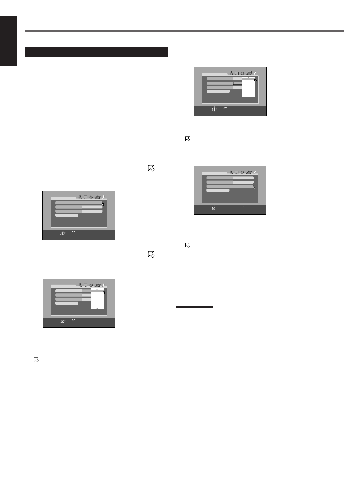
Choice Menu Operations
USE TO SELECT. USE ENTER TO CONFIRM.
TO EXIT, PRESS CHOICE.
ENTER
SELECT
CA
PARENTAL LOCK
COUNTRY CODE
SET LEVEL
PASSWORD
NONE
_ _ _ _
EXIT
5
4
8
3
NONE
7
6
USE TO SELECT. USE ENTER TO CONFIRM.
TO EXIT, PRESS CHOICE.
ENTER
SELECT
CA
PARENTAL LOCK
COUNTRY CODE
SET LEVEL
PASSWORD
NONE
_ _ _ _
EXIT
USE TO SELECT. USE ENTER TO CONFIRM.
TO EXIT, PRESS CHOICE.
ENTER
SELECT
CA
PARENTAL LOCK
COUNTRY CODE
SET LEVEL
PASSWORD
NONE
_ _ _ _
EXIT
CH
CI
CG
CC
CK
CA
CF
NEW PASSWORD? PRESS 0 9KEY.
TO EXIT, PRESS CHOICE.
ENTER
SELECT
CA
PARENTAL LOCK
COUNTRY CODE
SET LEVEL
PASSWORD
4
_ _ _ _
EXIT
English
Restricting Playback by Parental Lock
You can restrict playback of DVD VIDEO containing violent scenes
and those not suitable for your family members. Nobody can play
such a disc unless this function is canceled.
• This setting takes effect only for the DVD VIDEO containing the
Parental Lock level information—Level 1 (most restrictive) to
Level 8 (least restrictive).
• You can set the Parental Lock only while playback is stopped.
5
Press ENTER.
The pop-up window for setting level appears.
7 Setting Parental Lock
1
Press CHOICE, then press cursor 3 (or 2) to
display the OTHERS menu.
2
Press cursor ∞ (or 5) repeatedly to move to
“PARENTAL LOCK,” then press ENTER.
The PARENTAL LOCK submenu appears on the TV.
3
Press cursor ∞ (or 5) repeatedly to move to
“COUNTRY CODE,” then press ENTER.
The submenu for setting the country code appears.
6
Press cursor ∞ (or 5) repeatedly to select the
level of restriction, then press ENTER.
moves to “PASSWORD.”
• The smaller the value of level is, the more restrictive the
Parental Lock level is.
• Select “NONE” to cancel this function.
7
Press the number buttons (0–9) to enter a four
digit number as your password, then press
ENTER.
moves to “EXIT.”
8
Press ENTER.
OTHERS menu resumes.
To return to the normal screen
Press CHOICE.
4
53
Press cursor ∞ (or 5) repeatedly to select the
country code, then press ENTER.
See “Country/Area codes list for Parental Lock” on page 55.
moves to “SET LEVEL.”
Note:
• Remember your password or make a note of it.
You need to enter your password to change the setting or release
the lock. To change the setting, see page 54.
Page 57
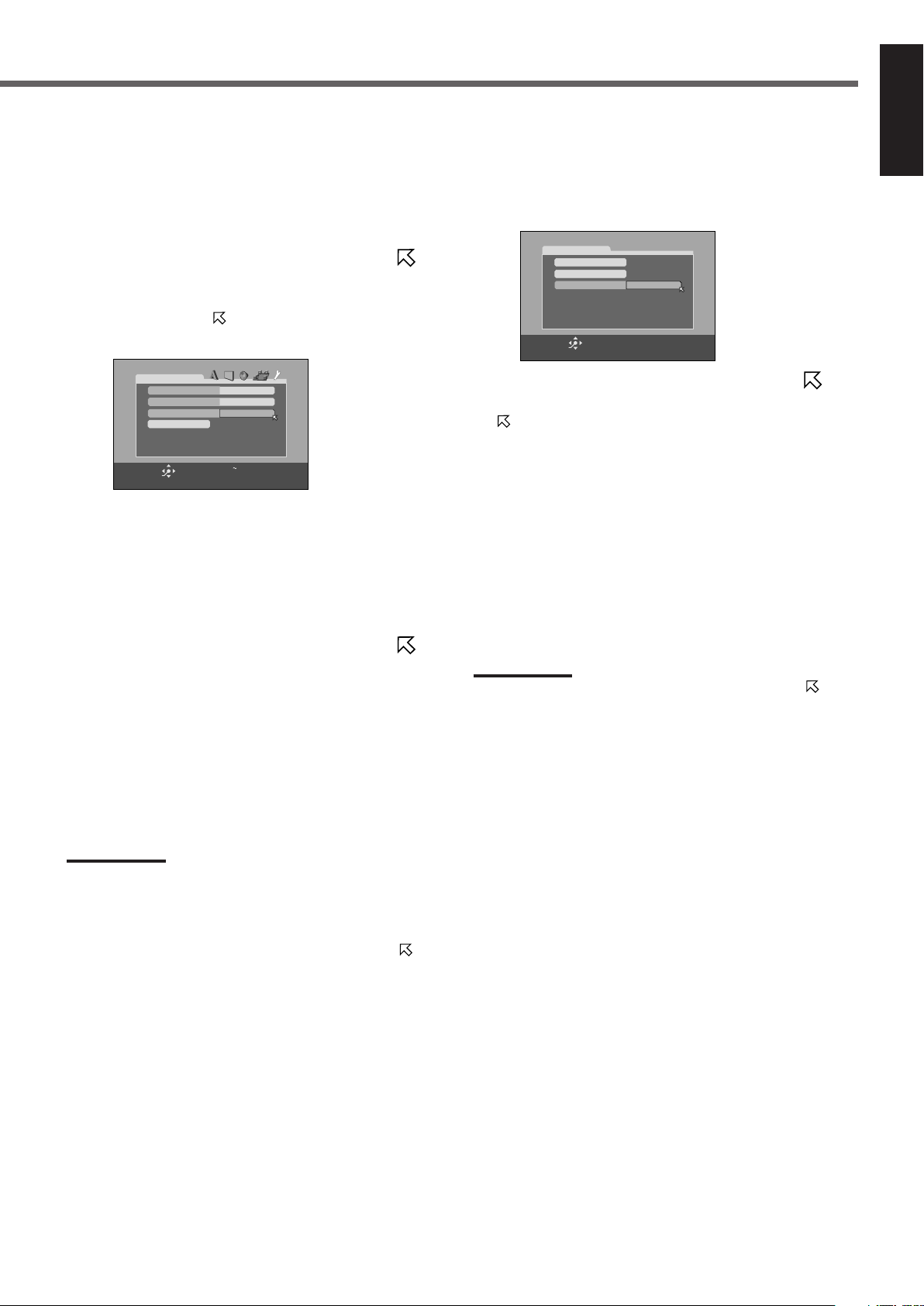
7 Changing the setting of Parental Lock
PASSWORD? PRESS 0 9KEY.
TO EXIT, PRESS CHOICE.
ENTER
SELECT
CA
PARENTAL LOCK
COUNTRY CODE
LEVEL
PASSWORD
4
_ _ _ _
EXIT
PARENTAL LOCK
PASSWORD
_ _ _ _
TEMPORARY RELEASE
PASSWORD? ••• PRESS 0 ~ 9 KEY
ENTER
SELECT
NOT RELEASE
1
Press CHOICE, then press cursor 3 (or 2) to
display the OTHERS menu.
2
Press cursor ∞ (or 5) repeatedly to move to
“PARENTAL LOCK,” then press ENTER.
The PARENTAL LOCK submenu appears on the TV.
• You can only move to “PASSWORD” or to “EXIT” before
you enter your password.
3
Press the number buttons (0–9) to enter your
password, then press ENTER.
• If you enter a wrong password, “WRONG! RETRY...” appears
on the PARENTAL LOCK submenu.
You cannot go to next steps before you enter the correct
password.
7 Releasing Parental Lock temporarily
When you set a strict parental level, some discs may not be played
back at all. When you load such a disc and try to play it, the
following display appears on the TV. You can release Parental Lock
temporarily.
1
Press cursor ∞ (or 5) repeatedly to move to
“TEMPORARY RELEASE”, then press ENTER.
moves to “PASSWORD.”
• If you do not want to release Parental Lock temporarily, select
“NOT RELEASE” by pressing cursor ∞ (or 5), then press
ENTER. To eject the disc, press 0.
2
Press number buttons (0–9) to enter your
password, then press ENTER.
Playback starts.
• If you enter a wrong password, “WRONG! RETRY...” appears
on the PARENTAL LOCK submenu.
You cannot play the disc before you enter the correct
password.
English
4
Press cursor ∞ (or 5) repeatedly to move to
the item you want to change, then press ENTER.
5
Press cursor ∞ (or 5) repeatedly to change the
setting, then press ENTER.
6
Press the number buttons (0–9) to enter your
password, then press ENTER.
The new setting is stored.
Notes:
• You cannot set the Parental Lock before you set your password.
• If you go out of the PARENTAL LOCK submenu before setting your
password in step 6, the new country code and parental level will not
become effective, and the old country code and parental level
remain effective.
• When you enter wrong passwords more than three times,
moves to “EXIT” automatically and cursor ∞ (or 5) does not work.
Press ENTER to exit from the PARENTAL LOCK submenu, then
start from step 1 again.
• If you forget your password, enter “8888.”
Note:
• When you enter wrong passwords more than three times,
moves to “NOT RELEASE” automatically and cursor ∞ (or 5) does
not work. Press 0 to remove the disc.
54
Page 58

Choice Menu Operations
Setting DVD preferences
English
Country/Area codes list for Parental Lock
AD Andorra
AE United Arab Emirates
AF Afghanistan
AG Antigua and Barbuda
AI Anguilla
AL Albania
AM Armenia
AN Netherlands Antilles
AO Angola
AQ Antarctica
AR Argentina
AS American Samoa
AT Austria
AU Australia
AW Aruba
AZ Azerbaijan
BA Bosnia and Herzegovina
BB Barbados
BD Bangladesh
BE Belgium
BF Burkina Faso
BG Bulgaria
BH Bahrain
BI Burundi
BJ Benin
BM Bermuda
BN Brunei Darussalam
BO Bolivia
BR Brazil
BS Bahamas
BT Bhutan
BV Bouvet Island
BW Botswana
BY Belarus
BZ Belize
CA Canada
CC Cocos (Keeling) Islands
CF Central African Republic
CG Congo
CH Switzerland
CI Côte d’Ivoire
CK Cook Islands
CL Chile
CM Cameroon
CN China
CO Colombia
CR Costa Rica
CU Cuba
CV Cape Verde
CX Christmas Island
CY Cyprus
CZ Czech Republic
DE Germany
DJ Djibouti
DK Denmark
DM Dominica
DO Dominican Republic
DZ Algeria
EC Ecuador
EE Estonia
EG Egypt
EH Western Sahara
ER Eritrea
ES Spain
ET Ethiopia
FI Finland
FJ Fiji
FK Falkland Islands (Malvinas)
FM Micronesia
FO Faroe Islands
FR France
FX France, Metropolitan
GA Gabon
GB United Kingdom
GD Grenada
GE Georgia
GF French Guiana
GH Ghana
GI Gibraltar
GL Greenland
GM Gambia
GN Guinea
GP Guadeloupe
GQ Equatorial Guinea
GR Greece
GS South Georgia and the
GT Guatemala
GU Guam
GW Guinea-Bissau
GY Guyana
HK Hong Kong
HM Heard Island and
HN Honduras
HR Croatia
HT Haiti
HU Hungary
ID Indonesia
IE Ireland
IL Israel
IN India
IO British Indian Ocean
IQ Iraq
IR
IS Iceland
IT Italy
JM Jamaica
JO Jordan
JP Japan
KE Kenya
KG Kyrgyzstan
KH Cambodia
KI Kiribati
KM Comoros
KN Saint Kitts and Nevis
KP Korea, Democratic
KR Korea, Republic of
KW Kuwait
KY Cayman Islands
KZ Kazakhstan
(Fedelated States of)
South Sandwich Islands
McDonald Islands
Territory
Iran (Islamic Republic of)
People’s Republic of
LA Lao People’s
Democratic Republic
LB Lebanon
LC Saint Lucia
LI Liechtenstein
LK Sri Lanka
LR Liberia
LS Lesotho
LT Lithuania
LU Luxembourg
LV Latvia
LY Libyan Arab Jamahiriya
MA Morocco
MC Monaco
MD Moldova, Republic of
MG Madagascar
MH Marshall Islands
ML Mali
MM Myanmar
MN Mongolia
MO Macau
MP
Northern Mariana Islands
MQ Martinique
MR Mauritania
MS Montserrat
MT Malta
MU Mauritius
MV Maldives
MW Malawi
MX Mexico
MY Malaysia
MZ Mozambique
NA Namibia
NC New Caledonia
NE Niger
NF Norfolk Island
NG Nigeria
NI Nicaragua
NL Netherlands
NO Norway
NP Nepal
NR Nauru
NU Niue
NZ New Zealand
OM Oman
PA Panama
PE Peru
PF French Polynesia
PG Papua New Guinea
PH Philippines
PK Pakistan
PL Poland
PM
Saint Pierre and Miquelon
PN Pitcairn
PR Puerto Rico
PT Portugal
PW Palau
PY Paraguay
QA Qatar
RE Réunion
RO Romania
RU Russian Federation
RW Rwanda
SA Saudi Arabia
SB Solomon Islands
SC Seychelles
SD Sudan
SE Sweden
SG Singapore
SH Saint Helena
SI Slovenia
SJ
Svalbard and Jan Mayen
SK Slovakia
SL Sierra Leone
SM San Marino
SN Senegal
SO Somalia
SR Suriname
ST Sao Tome and Principe
SV El Salvador
SY Syrian Arab Republic
SZ Swaziland
TC
Turks and Caicos Islands
TD Chad
TF
French Southern Territories
TG Togo
TH
Thailand Code Language
TJ Tajikistan
TK Tokelau
TM Turkmenistan
TN Tunisia
TO Tonga
TP East Timor
TR Turkey
TT Trinidad and Tobago
TV Tuvalu
TW
Taiwan
TZ Tanzania, United
Republic of
UA Ukraine
UG Uganda
UM United States Minor
Outlying Islands
US United States
UY Uruguay
UZ Uzbekistan
VA Vatican City State
(Holy See)
VC Saint Vincent and the
Grenadines
VE Venezuela
VG Virgin Islands (British)
VI Virgin Islands (U.S.)
VN Viet Nam
VU Vanuatu
WF
Wallis and Futuna Islands
WS Samoa
YE Yemen
YT Mayotte
YU Yugoslavia
ZA South Africa
ZM Zambia
ZR Zaire
ZW Zimbabwe
55
Page 59

Glossary for DVD Player
Aspect ratio
The ratio of vertical and horizontal sizes of a displayed image. The
horizontal vs. vertical ratio of conventional TVs is 4:3 and that of
wide-screen TVs is 16:9.
Chapter
The smallest division on DVD VIDEO. It is a division of a title and
similar to a track for CD or VCD.
Composite video signal
A video signal comprised of three kinds of signals combined: an
image signal made up of luminance and chrominance signals using
the frequency multiplication technique, burst signal providing the
basis for color reproduction, and synchronization signal.
Component video signal
A video signal system where parts of information necessary for
reproducing image signal comprised of the three primary colors of
light are transmitted via separate signal lines. Types of signal, such
as R/G/B, Y/P
B/PR, etc., are available.
Disc menu
A screen display prepared for allowing selection of images, sounds,
subtitles, multi-angle, etc. recorded on DVD VIDEO.
Interlaced scanning
In the conventional video system, a picture is shown on the display
monitor in two halves. The Interlaced scanning system places lines
of the second half of the picture in-between lines of the first half of
the picture.
JPEG
A still-picture data compression system proposed by the Joint
Photographic Expert Group, which features little distortion in image
quality in spite of its high compression ratio.
Linear PCM (PCM: Pulse Code Modulation)
A system for converting analog sound signal to digital signal for
later processing with no data compression used in conversion.
Letter box
A method of displaying wide images like movies in on a 4:3 TV
screen with no part of the image deleted by placing black bands on
the top and bottom of the screen. This name has derived from the
screen form looking literally like a letter box.
Multichannel
DVD VIDEO has been designed to have each soundtrack constitute
one sound field. Multichannel refers to a structure of sound tracks
having three or more channels.
Multilanguage
When a title is created to cope with multiple languages, it is
generally called a multilanguage title.
Parental Lock
A feature of this system to automatically determine whether or not
to reproduce particular DVD VIDEO software by comparing its
parental level (a measure of undesirability of scenes, etc. from
educational viewpoint) set for the software beforehand with that set
on this system by the user; if the software’s level is less restrictive
than the user-set level, it will be reproduced.
Playback control (PBC)
Refers to the signal recorded on VCD/SVCD for controlling
reproduction. By using menu screens recorded on VCD/SVCD that
supports PBC, you can enjoy interactive-type software as well as
software having a search function.
Progressive scanning
By progressive scanning, all the horizontal lines of a picture are
displayed at one time as a single frame. This system can convert the
interlaced video from DVD VIDEO into progressive format for
connection to a progressive TV. It dramatically increases the vertical
resolution.
Region code
A system for allowing discs to be played back only in the regions
designated beforehand. All the countries in the world are divided
into six regions and each region is identified by a specified region
code (or region number). If the region code of a disc matches that of
a player, the player can play back the disc.
Surround
A system for creating three-dimensional sound fields full of realism
by arranging multiple speakers around the listener.
Sampling frequency
Frequency of sampling data when analog data is converted to digital
data. Sampling frequency numerically represents how many times
the original analog signal is sampled per second.
English
MP3
A file format with a sound data compression system. “MP3” is the
abbreviation of Motion Picture Experts Group 1 (or MPEG-1) Audio
Layer 3. By using MP3 format, one CD-R or CD-RW can contain
about 10 times as much data volume as a regular CD can.
Multi-angle
By recording multiple scenes progressing at the same time in a
single title, the user can select view angles. This feature is called the
multi-angle function.
Transfer rate
The rate of transferring digital data. Usually the measure is in bit per
second (bps). The DVD system applies a variable transfer rate
system for high efficiency.
56
Page 60

To Video Input 1
TV
RX-DV3SL
S-video cable
S-video cable
Source
Equipment
To Video Input 2
Composite
video cable
Composite
video cable
TV
RX-DV3SL
Source
Equipment
To Video Input 2
Component
video cable
TV
RX-DV3SL
AV COMPU LINK Remote Control System
AV
COMPU LINK III
AV
COMPU LINK
AV
COMPU LINK
EX
AV COMPU LINK-
English
The AV COMPU LINK remote control system allows you to operate JVC’s video components (TV and VCR) through the unit.
This unit is equipped with the AV COMPU LINK-III, which has added a function to operate JVC’s video components through the video
components terminals. To use this remote control system, you need to connect the video components you want to operate, following the
diagrams below and the procedures on page 58.
• Refer also to the manuals supplied with your video components.
CONNECTIONS 1: AV COMPU LINK Connection
VCR
TV
CAUTION:
When connecting the TV with the
AV COMPU LINK remote control
system, connect the unit to the
AV COMPU LINK III or
AV COMPU LINK EX terminal.
DO NOT connect the unit to the
AV COMPU LINK RECEIVER/AMP
terminal.
Notes:
• When connecting the unit and a TV with the AV COMPU LINK EX terminal by using a component video cable, you cannot use Automatic
Selection of TV’s Input Mode (see page 58).
• When connecting the VCR only to this unit, connect it directly to the unit using cables with the monaural mini-plugs.
CONNECTIONS 2: Video Cable Connection
This unit is equipped with three types of the video terminals—composite video, S-video, and component video, and the signals coming into
this unit through one type of video terminals can output only through the terminal of the same type. So you need to connect the VCR and TV
to this unit using one of the following two ways—CASE 1 or 2:
• When using the AV COMPU LINK remote control system, set the component video input correctly (see “Video output mode” on
page 22); otherwise, the correct input for this unit will not be selected on the TV.
CASE 1 When connecting the source equipment to the unit through the S-video terminals, connect this unit to the
TV’s Video Input 1 terminal using S-video cables.
57
CASE 2 When connecting the source equipment to the unit through the composite video terminals, connect this
unit to the TV’s Video Input 2 terminal (composite video input) using composite video cables.
CASE 3 When setting the video output mode of the built-in DVD player to “component,” connect this unit to the
TV’s Video Input 2 terminals (component video input) using component video cables.
Page 61

1. If you have already plugged your VCR, TV, and
this unit into the AC outlets, unplug their AC
power cords first.
2. Connect your VCR, TV, and this unit following
“CONNECTIONS 1” on the previous page, using
the cables with the monaural mini-plugs (not
supplied).
3. Connect the audio input/output jacks on VCR,
TV, and this unit using the audio cords.
• See pages 7 to 9.
One-Touch DVD Play
Simply by starting playback on the built-in DVD player, you can
enjoy the playback without setting other switches manually.
The TV automatically turns on and changes the input mode to the
appropriate position so that you can view the playback picture.
Automatic Selection of TV’s Input Mode
• When you select TV as the source to play on the unit, the TV
automatically changes the input mode to the TV tuner so that you
can watch TV.
• When you select DVD, VCR, or DBS as the source to play on the
unit, the TV automatically changes the input mode to the
appropriate position so that you can view the playback picture.
English
4. Connect the video input/output jacks on VCR,
TV and this unit following “CONNECTIONS 2”
on the previous page, using the composite video
cord, with S-video plug or with component video
plugs.
5. Plug the AC power cords of the components into
the AC outlets.
6. When turning on the TV for the first time after
the AV COMPU LINK connection, turn the TV
volume to the minimum using the TV volume
control on the TV.
7. Turn on other connected components first, then
turn on this unit.
• When turning on the VCR, use the remote control supplied
with this unit–press STANDBY/ON VCR.
The AV COMPU LINK remote control system allows you to use the
five basic functions listed below.
Remote Control of the TV and VCR Using This
Remote Control
For details, see page 60 .
• Aim the remote control directly at the remote sensor on each
target component.
Notes:
• When connecting a TV with the AV COMPU LINK EX terminal to
this unit, you cannot use a component video cable (as CASE 3 on
the previous page).
• When you select TV as the source on the unit, you cannot see the
menu on the TV screen since the AV COMPU LINK remote control
system automatically changes the TV’s input mode to the TV tuner.
If you do not mind stopping listening to the TV sounds, you can
then show the on-screen menu after changing the TV’s input mode
to the appropriate position the unit is connected to.
Automatic Power On/Off
The TV and VCR turn on and off along with the unit.
When you turn on the unit;
• If the previously selected source is VCR, the TV and VCR will
turn on automatically.
• If the previously selected source is TV or DVD, only the TV will
turn on automatically.
When you turn off the unit, the TV and VCR will turn off.
Note:
• If you turn off the unit while recording on the VCR, the VCR will not
turn off, but continue recording.
One-Touch Video Play
Simply by inserting a video cassette without its safety tab into the
VCR, you can enjoy the video playback without setting other
switches manually. The unit automatically turns on and changes the
source to VCR.
The TV automatically turns on and changes the input mode to the
appropriate position so that you can view the playback picture.
When you insert a video cassette with its safety tab, press the play
(3) button on the VCR or on the remote control. You can get the
same result.
58
Page 62

Operating JVC’s Audio/Video Components
231
564
89
7
VFP
10/0 +10
100+ TV RETURN
VCRDBS DVD
TV/VIDEO REW/(TUNING
9
/FF
REPEAT SLEEP
TAPETV CDR FM/AM
FM MODE STROBE
EFFECT
– TV/DBS CH +
ANALOG
/DIGITAL
TEST
AUDIO
INPUT
SUBTITLE
SURR ON/OFF
SURR MODE
–
SUBWOOFER
+
SOUND
CENTER
REAR·L
REAR·R
231
564
89
7
VFP
10/0 +10
100+ TV RETURN
VCRDBS DVD
TV/VIDEO REW/(TUNING
9
/FF
REPEAT SLEEP
TAPETV CDR FM/AM
FM MODE STROBE
EFFECT
– TV/DBS CH +
ANALOG
/DIGITAL
TEST
AUDIO
INPUT
SUBTITLE
SURR ON/OFF
SURR MODE
–
SUBWOOFER
+
SOUND
CENTER
REAR·L
REAR·R
231
564
89
7
VFP
10/0 +10
100+ TV RETURN
EFFECT
– TV/DBS CH +
ANALOG
/DIGITAL
TEST
AUDIO
INPUT
SUBTITLE
SURR ON/OFF
SURR MODE
–
SUBWOOFER
+
SOUND
CENTER
REAR·L
REAR·R
English
You can operate JVC’s audio and video components with this unit’s remote control, since control signals for JVC’s components are preset in the
remote control.
Operating Audio Components
To operate JVC’s audio components using this remote control
• Aim the remote control directly at the remote sensor on the unit.
• To operate a source with the remote control, the source must be
selected using the source selecting buttons on the remote control.
• Refer also to the manuals supplied with your components.
7 Sound control section (Amplifier)
After pressing SOUND, you can perform the following operations:
SURR ON/OFF : Turns on or off the Surround modes—
Dolby Digital, DTS Digital Surround, and
Dolby Pro Logic II.
SURR MODE : Selects the Surround modes.
TEST : Turns on or off the test tone output.
CENTER + or – : Adjusts the center speaker channel output
level.
REAR•L + or – : Adjusts the left rear speaker channel
output level.
REAR•R + or – : Adjusts the right rear speaker channel
output level.
SUBWOOFER + or – : Adjusts subwoofer channel output level.
EFFECT : Selects the effect level.
Note:
• After adjusting sounds, press the source selecting button to operate
your target source by using number buttons; otherwise, number
buttons cannot be used for operating your target source.
7 CD recorder
After pressing CDR, you can perform the following operations on a CD
player and a CD recorder:
3 : Starts playing.
4 : Returns to the beginning of the current (or previous)
track.
¢ : Skips to the beginning of the next track.
7 : Stops playing.
8 : Pauses playing. To release it, press 3.
1 – 10, +10 : Selects a track number directly.
For track number 5, press 5.
For track number 15, press +10, then 5.
For track number 20, press +10, then 10.
For track number 30, press +10, +10, then 10.
Note:
• When you start recording on the CD recorder, use the buttons on
the CD recorder itself or on the remote control supplied with it.
7 Tuner
You can always perform the following operations:
59
FM/AM : Tunes into the last selected FM or AM station.
• Each time you press the button, the band changes between FM and
AM alternately.
After pressing FM/AM, you can perform the following operations on
a tuner:
1 – 10, +10 : Selects a preset channel number directly.
For channel number 5, press 5.
For channel number 15, press +10, then 5.
For channel number 20, press +10, then 10.
TUNING 9 or ( : Tunes into stations.
FM MODE : Changes the FM reception mode.
Page 63

Operating Video Components
231
564
89
7
VFP
10/0 +10
100+ TV RETURN
VCRDBS DVD
TV/VIDEO REW/(TUNING
9
/FF
REPEAT SLEEP
VCRDBS TV AUDIO
TAPETV CDR FM/AM
FM MODE STROBE
EFFECT
– TV/DBS CH +
ANALOG
/DIGITAL
TEST
AUDIO
INPUT
SUBTITLE
SURR ON/OFF
SURR MODE
–
SUBWOOFER
+
SOUND
STANDBY/ON
CENTER
REAR·L
REAR·R
+–+
–
231
564
89
7
VFP
10/0 +10
100+ TV RETURN
VCRDBS DVD
TV/VIDEO REW/(TUNING
9
/FF
REPEAT SLEEP
VCRDBS TV AUDIO
TAPETV CDR FM/AM
FM MODE STROBE
EFFECT
– TV/DBS CH +
ANALOG
/DIGITAL
TEST
AUDIO
INPUT
SUBTITLE
ANGLE
ZOOM
SURR ON/OFF
SURR MODE
DIMMER
MUTING
TV VOL VOLUME
–
SUBWOOFER
+
SOUND
STANDBY/ON
CENTER
REAR·L
REAR·R
PROGRESSIVE
To operate JVC’s video components using this remote control
• You need to connect JVC’s video components through the
AV COMPU LINK-III jacks (see page 57) in addition to the
audio/video connections (see pages 7 to 10).
• Some JVC’s VCRs can accept two types of the control signals—
remote codes “A” and “B.” Before using this remote control, make
sure that the remote control code of the connected VCR is set to
code “A.”
• To operate the video component(s) using the remote control, aim
the remote control directly at the remote sensor on each
component, not on this unit.
7 TV
You can always perform the following operations:
7 VCR
You can always perform the following operations:
STANDBY/ON VCR : Turns on or off the VCR.
After pressing VCR, you can perform the following operations on a
VCR:
1 – 9, 0 : Selects the TV channels on a VCR.
For channel number 5, press 5.
For channel number 10, press 1, then 0.
For channel number 23, press 2, then 3.
3 : Starts playing.
REW : Rewinds a tape.
FF : Fast-winds a tape.
7 : Stops operations.
8 : Pauses playing. To release it, press 3.
English
STANDBY/ON TV : Turns on or off the TV.
TV VOL + or – : Adjusts the volume.
TV/VIDEO : Sets the input mode (either TV or
VIDEO).
After pressing TV, you can perform the following operations on a TV:
TV/DBS CH + or – : Changes the channels.
1 – 9, 0, 100+ : Selects the channels.
For channel number 5, press 5.
For channel number 10, press 1, then 0.
For channel number 23, press 2, then 3.
For channel number 135, press 100+, 3,
then 5.
TV RETURN : Alternates between the previously
selected channel and the current
channel.
60
Page 64

Operating Other Manufacturers’ Equipment
VCRDBS TV AUDIO
STANDBY/ON
231
564
89
7
10/0 +10
100+
EFFECT
TEST
SURR ON/OFF
SURR MODE
–
SUBWOOFER
+
CENTER
REAR·L
REAR·R
VCRDBS DVD
TAPETV CDR FM/AM
English
This remote control supplied with the unit can transmit control signals for other manufacturers’ TVs, DBS tuners, and VCRs.
By changing the transmittable signals from preset ones to other manufacturers’, you can operate other manufacturers’ components using this
remote control.
Changing the Preset Signal Codes
To operate other manufacturers’ equipment using this remote
control
• Aim the remote control directly at the remote sensor on each
equipment.
• To operate a source with the remote control, the source must be
selected using source selecting buttons on the remote control.
• Refer also to the manuals supplied with your equipment.
7 To change the transmittable signals for
operating other manufacturers’ TV
1. Press and hold
STANDBY/ON TV.
2. Press TV.
Enter the manufacturer’s code
3.
using the number buttons (1–9, 0).
See the right to find the code.
4. Release STANDBY/ON TV.
You can perform the following operations on the TV:
STANDBY/ON TV : Turns on or off the TV.
TV VOL + or – : Adjusts the volume.
TV/VIDEO : Sets the input mode (either TV or
VIDEO).
After pressing TV, you can perform the following operations on
a TV:
TV/DBS CH + or – : Changes the channels.
1 – 9, 0, 100+ : Selects the channels.
For channel number 5, press 5.
For channel number 10, press 1, then 0.
For channel number 23, press 2, then 3.
For channel number 135, press 100+,
3, then 5.
TV RETURN will function as the
ENTER button if your equipment
requires pressing ENTER after
61
selecting a channel number.
Notes:
• Refer also to the manual supplied for your TV.
• All the functions listed on the left may not be assigned to the
buttons for some TVs.
• If you cannot change the channels of some TVs by pressing
the number buttons, press TV/DBS CH + or – for changing the
channels.
5. Try to operate your TV by pressing
STANDBY/ON TV.
When your TV turns on or off, you have entered the correct
code.
If there are more than one code listed for your brand of TV,
try each one until the correct one is entered.
Manufactures’ codes for TV
Manufacturer Codes
JVC 00*, 02, 13, 14, 47, 74
Akai 01, 02
Blaupunkt 03, 04
Fisher 01, 05
Grundig 03, 06, 07
Hitachi 08 – 10, 49
Iraddio 02
Itt/Nokia 11, 12
Loewe 06, 15, 16
Magnavox 08, 17, 49
Mets 50 – 53
Mitsubishi 08, 18 – 20
Mivar 21
Nordmende 22, 23
Okano 15
Panasonic 24 – 27, 76
Philips 15, 17, 28, 75
Quelle 52 – 67
RCA/PROSC 08, 24, 29 – 31, 48
SABA 32, 33, 68 – 70
Samsung 06, 08, 16, 34, 35, 49
Sanyo 01, 05
Schneider 02, 15, 36
Sharp 37, 38, 77
Sony 39
Telefunken 40 – 42, 69
Thomson 71, 72
Toshiba 37, 43, 44
Zenith 45, 46
*“00” is the initial JVC code.
Note:
• Manufacturers’ codes are subject to change without notice. If
they are changed, this remote control cannot operate the
equipment.
Page 65
7 To change the transmittable signals for
VCRDBS DVD
TAPETV CDR FM/AM
231
564
89
7
10/0 +10
100+
EFFECT
TEST
SURR ON/OFF
SURR MODE
–
SUBWOOFER
+
CENTER
REAR·L
REAR·R
VCRDBS TV AUDIO
STANDBY/ON
operating other manufacturers’ DBS tuner
1. Press and hold
STANDBY/ON DBS.
2. Press DBS.
3. Enter manufacturer’s code using
the number buttons (1–9, 0).
See to the right to find the code.
4. Release STANDBY/ON DBS.
You can turn on and off the DBS tuner:
STANDBY/ON DBS : Turns on or off the DBS tuner.
After pressing DBS, you can perform the following operations
on a DBS tuner:
TV/DBS CH + or – : Changes the channels.
1 – 9, 0, 100+ : Selects the channels.
For channel number 5, press 5.
For channel number 10, press 1, then 0.
For channel number 23, press 2, then 3.
For channel number 135, press 100+, 3,
then 5.
TV RETURN will function as the
ENTER button if your equipment
requires pressing ENTER after selecting a
channel number.
Note:
• Refer also to the manual supplied for your DBS tuner.
Manufactures’ codes for DBS tuner
Manufacturer Codes
JVC 56, 57*, 67
Amstrad 43 – 49
Blaupunkt 30
Echostar 50, 51, 67
General Instrument 29
Goldstar 31
Grundig 32, 33
Hamlin/Re 01 – 05
Hirshmann 48, 52 – 55
Instrument 68
Itt/Nokia 34
Jerrold/G 06 – 14
Kathrein 52, 58 – 63
NEC 35, 36
Oak 15 – 17
Orbitech 48
Panasonic 18 – 20
Philips 37, 38
Pioneer 21, 22
RCA 65
Samsung 39, 40
Schwaiger 61, 64
Scientiff 23 – 25
Siemens 41, 42
Sony 66
Technisat 48
Tocom 26
Zenith 27, 28
*“57” is the initial JVC code.
Note:
• Manufacturers’ codes are subject to change without notice. If
they are changed, this remote control cannot operate the
equipment.
English
5. Try to operate your DBS tuner by pressing
STANDBY/ON DBS.
When your DBS tuner turns on or off, you have entered the
correct code.
If there are more than one code listed for your brand of DBS
tuner, try each one until the correct one is entered.
62
Page 66

Operating Other Manufacturers’ Equipment
VCRDBS TV AUDIO
STANDBY/ON
231
564
89
7
10/0 +10
100+
EFFECT
TEST
SURR ON/OFF
SURR MODE
–
SUBWOOFER
+
CENTER
REAR·L
REAR·R
VCRDBS DVD
TAPETV CDR FM/AM
English
7 To change the transmittable signals for
operating other manufacturers’ VCR
1. Press and hold
STANDBY/ON VCR.
2. Press VCR.
3. Enter the manufacturer’s code
using the number buttons (1–9, 0).
See the right to find the code.
4. Release STANDBY/ON VCR.
You can turn on and off the VCR:
STANDBY/ON VCR : Turns on or off the VCR.
After pressing VCR, you can perform the following operations
on a VCR:
1 – 9, 0 : Selects the TV channels on a VCR.
For channel number 5, press 5.
For channel number 10, press 1, then 0.
For channel number 23, press 2, then 3.
TV RETURN will function as the ENTER button if
your equipment requires pressing ENTER after
selecting a channel number.
3 : Starts playing.
REW : Rewinds a tape.
FF : Fast-winds a tape.
7 : Stops operations.
8 : Pauses playing. To release it, press 3.
Manufactures’ codes for VCR
Manufacturer Codes
JVC 00*, 26 – 29, 58
Aiwa 01, 02
Bell & Howell 03
Blaupunkt 04, 05
CGM 06, 07
Emerson 08, 10 – 12, 64, 65
Fisher 03, 14 – 17
Funai 01
GE 18 – 20
Goldstar 07
Goodmans 13, 21
Grundig 06, 22
Hitachi 18, 23 – 25, 66
Loewe 07, 21
Magnavox 04, 19, 24
Mitsubishi 30 – 35
NEC 26, 27
Nokia 03, 36
Nordmende 38
Orion 09
Panasonic 19, 24, 39, 40
Philips 04, 19, 21, 24, 41, 42
Phonola 21
RCA/PROSC 04, 18, 19, 23, 24, 43 – 45
SABA 38, 46
Samsung 45, 47, 59, 61 – 63
Sanyo 03, 48, 49
Sharp 37, 50
Siemens 03, 51
Sony 52 – 54
Telefunken 55, 60
Toshiba 43, 44
Zenith 56, 57
*“00” is the initial JVC code.
Note:
• Manufacturers’ codes are subject to change without notice. If
they are changed, this remote control cannot operate the
equipment.
Note:
• Refer also to the manual supplied for your VCR.
5. Try to operate your VCR by pressing
STANDBY/ON VCR.
When your VCR turns on or off, you have entered the correct
code.
If there are more than one code listed for your brand of
VCR, try each one until the correct one is entered.
63
Page 67

Maintenance
To get the best performance of the system, keep your discs and mechanism clean.
General Notes
In general, you will have the best performance by keeping your discs
and mechanism clean.
• Store discs in their cases, and keep them in cabinets or on shelves.
Cleaning Discs
Wipe the disc with a soft cloth in a straight line from center to edge.
Handling Discs
• Remove the disc from its case by holding it at the edge while
pressing the center hole lightly.
• Do not touch the shiny surface of the disc, or bend the disc.
• Put the disc back in its case after use to prevent warping.
DO NOT use any solvent—such as conventional record
cleaner, spray, thinner, or benzine—to clean the disc.
Cleaning the Unit
• Stains on the unit
• Be careful not to scratch the surface of the disc when placing it
back in its case.
• Avoid exposure to direct sunlight, temperature extremes, and
moisture.
Should be wiped off with a soft cloth. If the unit is heavily stained,
wipe it with a cloth soaked in water-diluted neutral detergent and
wrung well, then wipe clean with a dry cloth.
• Since the unit may deteriorate in quality, become damaged or get
its paint peeled off, be careful about the following.
— DO NOT wipe it with a hard cloth.
— DO NOT wipe it strong.
— DO NOT wipe it with thinner or benzine.
DO NOT apply any volatile substances such as insecticides to it.
—
— DO NOT allow any rubber or plastic to remain in contact with
it for a long time.
English
64
Page 68
Troubleshooting
English
Use this chart to help you solve daily operational problems. If there is any problem you cannot solve, contact your dealer.
7 Genaral
PROBLEM
The power does not come on.
No sound from speakers.
Sound from one speaker only.
“OVERLOAD” starts flashing on the
display.
The STANDBY lamp lights up after
turning on the power, but soon the unit
turns off (into standby mode).
Remote control does not operate as you
intend.
Remote control does not work.
POSSIBLE CAUSE
The power cord is not plugged in.
Speaker signal cables are not
connected.
The audio cable is not connected
properly.
An incorrect source is selected.
Muting is activated.
An incorrect input mode (analog or
digital) is selected.
Connections are incorrect.
The balance is set to one extreme.
Speakers are overloaded because of
high volume.
Speakers are overloaded because of
short circuit of speaker terminals.
The unit is overloaded because of a
high voltage.
The remote control is not ready for
your intended operation.
It is too far from the unit, or is not
facing the unit.
There is an obstruction hiding the
remote sensor on the unit.
The remote control is not aimed at the
remote sensor on the unit or
components.
The batteries have been inserted into
the wrong way round (+/–).
Batteries are weak.
The remote control signals are not set
correctly.
SOLUTION
Plug the power cord into an AC outlet.
Check speaker wiring and reconnect if
necessary.
Connect the cord properly (see pages 7 to
10).
Select the correct source.
Press MUTING to cancel the muting.
Select the correct input mode (analog or
digital).
Check connections.
Adjust the balance properly (see pages 24 or
50).
1. Press
panel to turn off the unit.
2. Stop the playback source.
3. Turn on the unit again, and adjust the
volume.
Press
to turn off the unit, then check the speaker
wiring.
If “OVERLOAD” does not disappear,
unplug the AC power cord, then plug it back
again.
If speaker wiring is not short-circuited,
contact your dealer.
Press
to turn off the unit. After unplugging the
power cord, consult your dealer.
Press SOUND (see page 24) or a source
selecting button first, then press the buttons
you want to use.
Come closer to the unit. Operate the remote
control within 7 m (23 ft) from the unit.
Remove the obstruction.
Aim the remote control at the remote sensor
on each component you want to operate.
Insert the batteries correctly.
Replace batteries.
Enter the correct manufacturers’ code (see
pages 61 to 63).
STANDBY/ON on the front
STANDBY/ON on the front panel
STANDBY/ON on the front panel
65
Page 69

7 For DVD Player
English
PROBLEM
No picture is displayed on the TV.
No picture is displayed on the TV
screen, the picture is blurred, or the
picture is divided into two parts.
A disc cannot be played.
A disc cannot be played and “0:00” is
displayed on the display window.
Video and audio are distorted.
The picture does not fit the TV screen
properly.
One-touch DVD playback does not
work though you have connected AV
COMPU LINK cord correctly.
No subtitle appears on the TV screen
though you have selected as your initial
subtitle language.
Audio language is different from the
one you have selected as your initial
audio language.
POSSIBLE CAUSE
The video cord is not connected
correctly.
TV input selection is incorrect.
The disc is not playable.
The scan mode is set to
“PROGRESSIVE” though the unit is
connected to the TV which does not
support the progressive video input,
such as a conventional TV.
The unit’s and disc’s Region Code
numbers are incompatible.
Parental Lock is in use.
The disc is loaded with its label and
data sides inverted.
The unplayable disc is loaded.
The disc is scratched or dirty.
A VCR is connected between the unit
and the TV.
With some discs, a picture may be
blurred when setting “PROGRESSIVE
MODE” to “FILM” or “AUTO.”
“MONITOR TYPE” is not set correctly.
The TV is not set correctly.
The video output mode setting is
incorrect.
SOLUTION
Connect the cord correctly (see page 8).
Select the correct input on the TV.
Replace the disc (see page 29).
Change the scan mode to “INTERLACE”
(see page 14).
Replace the disc (see page 29).
Enter your password to change the parental
level (see pages 53 and 54).
Insert the disc correctly (see page 15).
Replace the disc (see page 29).
Replace or clean the disc (see page 64).
Connect the unit and TV directly.
Set “PROGRESSIVE MODE” to “VIDEO”
(see page 49).
Set the monitor type correctly (see page 49).
Set the TV correctly.
Set the video output mode correctly
according to the video connection between
your TV and the unit (see page 22).
Some discs are programmed to always
display no subtitle initially. If this happens,
press SUBTITLE on the remote control
after starting play (see page 35).
Some discs are programmed to always use
the original language initially. If this
happens, press AUDIO on the remote
control after starting play (see page 35).
66
Page 70

Troubleshooting
English
7 For Tuner
PROBLEM
Hard to listen to broadcast because of
noise.
Continuous hiss or buzzing during FM
reception.
Occasional cracking noise during FM
reception.
7 For MP3
POSSIBLE CAUSE
The AM loop antenna is too close to the
unit.
The supplied FM antenna is not
properly extended and positioned.
Incoming signal is too weak.
The station is too far away.
An incorrect antenna is used.
Antennas are not connected properly.
Ignition noise from automobiles.
SOLUTION
Change the position and direction of the AM
loop antenna.
Extend the FM antenna at the best position.
Connect an outdoor FM antenna or contact
your dealer.
Select a new station.
Check with your dealer to be sure you have a
correct antenna.
Check connections.
Move the antenna farther from automobile
traffic.
PROBLEM
A disc cannot be played.
No MP3 files except JPEG files are
played.
7 For JPEG
PROBLEM
A disc cannot be played.
No JPEG files except MP3 files are
played.
POSSIBLE CAUSE
No MP3 files are recorded on the disc.
The disc is unplayable (such as CD-
ROM).
MP3 files do not have the correct file
extension—.mp3, .Mp3, .mP3, or .MP3
in their file names.
MP3 files are made at bit rate under
64 kbps.
MP3 files are not recorded in the format
compliant with ISO 9660 Level 1 or 2.
The MP3/JPEG setting is set to
“JPEG.”
POSSIBLE CAUSE
No JPEG files are recorded on the disc.
The disc is unplayable (such as CD-
ROM).
JPEG files do not have the correct file
extension in their file names.
JPEG files are not made with baseline
JPEG format.
JPEG files are not recorded in the
format compliant with ISO 9660 Level
1 or 2.
The MP3/JPEG setting is set to “MP3.”
SOLUTION
Replace the disc.
Add the file extension—.mp3, .Mp3, .mP3,
or .MP3—to their file names (see page 43).
This unit cannot play back such files.
Replace the disc.
Replace the disc. (Record MP3 files using a
compliant application.)
When both MP3 files and JPEG files are
recorded on a disc, to play MP3 files, set the
MP3/JPEG setting to “MP3” (see page 50).
SOLUTION
Replace the disc.
Add the file extension—.jpg, .jpeg, .JPG,
.JPEG or any uppercase and lowercase
combination (such as “.Jpg”)—to their file
names (see page 45).
This unit cannot play back such files.
Replace the disc.
Replace the disc. (Record JPEG files using a
compliant application.)
When both MP3 files and JPEG files are
recorded on a disc, to play JPEG files, set
the MP3/JPEG setting to “JPEG” (see page
50).
67
Page 71

Specifications
Designs & specifications are subject to change without notice.
Amplifier
Output Power At Stereo operation:
Front channels: 100 W per channel, min. RMS, driven into 8
W, 40 Hz to 20 kHz with no more than 0.8%
total harmonic distortion.
At Surround operation:
Front channels: 100 W per channel, min. RMS, driven into 8 Ω
at 1 kHz, with no more than 0.8% total harmonic
distortion.
Center channel: 100 W, min. RMS, driven into 8 Ω
at 1 kHz, with no more than 0.8% total harmonic
distortion.
Rear channels: 100 W per channel, min. RMS, driven into 8 Ω
at 1 kHz, with no more than 0.8% total harmonic
distortion.
Audio
Audio Input Sensitivity/Impedance (1 kHz): TV, TAPE/CDR, DBS, VCR: 240 mV/47 kΩ
Audio Input (DIGITAL IN)* : Coaxial: DIGITAL 1 (DBS): 0.5 V(p-p)/75 Ω
Optical: DIGITAL 2 (TV): –21 dBm to –15 dBm (660 nm ±30 nm)
* Corresponding to Linear PCM, Dolby Digital, and DTS Digital Surround
(with sampling frequency—32 kHz, 44.1 kHz, 48 kHz).
Signal-to-Noise Ratio (’66 IHF/’78 IHF): TV, TAPE/CDR, DBS, VCR: 87 dB/67 dB
Frequency Response (8 Ω): TV, TAPE/CDR, DBS, VCR: 20 Hz to 20 kHz (±1 dB)
Tone Control: Bass (100 Hz): ±10 dB ±2 dB
Treble (10 kHz): ±10 dB ±2 dB
Video
Video Input Sensitivity/Impedance (1 kHz):
Composite video: DBS IN, VCR IN: 1 V(p-p)/75 Ω
S-video: DBS IN, VCR IN: (Y:luminance): 1 V(p-p)/75 Ω
(C:chrominance): 0.286 V(p-p)/75 Ω
English
Video Output Level/Impedance (1 kHz):
Composite video: VCR OUT, MONITOR OUT:
Component video: DVD COMPONENT VIDEO OUT:
Horizontal Resolution: 500 lines
Signal-to-Noise Ratio (S/N): 63 dB
FM tuner (IHF)
AM tuner
General
Power Requirements: AC 120V , 60 Hz
Power Consumption: 200 W/255 VA (in operation)
Dimensions (W x H x D): 435 mm x 100 mm x 403.5 mm
S-video: VCR OUT, MONITOR OUT:
Color System: NTSC
Synchronize: Negative
Tuning Range: 87.5 MHz to 108.0 MHz
Tuning Range: 530 kHz to 1 710 kHz
2 W (in standby mode)
(17 3/16 in. x 3 15/16 in. x 15 14/16 in.)
Mass: 7.9 kg (17.4 lbs)
1 V(p-p)/75 Ω
(Y:luminance): 1 V(p-p)/75 Ω
(C:chrominance): 0.286 V(p-p)/75 Ω
(Component-Y): 1.0 V(p-p)/75 Ω
(Component-PB/PR):
0.7 V(p-p)/75 Ω
68
Page 72

VICTOR COMPANY OF JAPAN, LIMITED
JVC
EN, FR
0502NHMMDWJEM
 Loading...