

Page 1
SERVICE MANUAL
HOME CINEMA DVD-AUDIO/VIDEO CONTROL CENTER
MB077200310
RX-DV31SL
Area Suffix
US ------------------ Singapore
UF ------------------------ China
UP ------------------------ Korea
UT ----------------------- Taiwan
UW ------- Brazil,Mexico,Peru
RX-DV31 HOME THEATER DVD-AUDIO/VIDEO RECEIVER
COMPACT
SUPER VIDEO
DVD/SUPER VCD/VCD/CD
TABLE OF CONTENTS
1 PRECAUTION. . . . . . . . . . . . . . . . . . . . . . . . . . . . . . . . . . . . . . . . . . . . . . . . . . . . . . . . . . . . . . . . . . . . . . . . . 1-3
2 SPECIFIC SERVICE INSTRUCTIONS. . . . . . . . . . . . . . . . . . . . . . . . . . . . . . . . . . . . . . . . . . . . . . . . . . . . . . 1-5
3 DISASSEMBLY . . . . . . . . . . . . . . . . . . . . . . . . . . . . . . . . . . . . . . . . . . . . . . . . . . . . . . . . . . . . . . . . . . . . . . . 1-6
4 ADJUSTMENT . . . . . . . . . . . . . . . . . . . . . . . . . . . . . . . . . . . . . . . . . . . . . . . . . . . . . . . . . . . . . . . . . . . . . . . 1-21
5 TROUBLESHOOTING . . . . . . . . . . . . . . . . . . . . . . . . . . . . . . . . . . . . . . . . . . . . . . . . . . . . . . . . . . . . . . . . . 1-22
COPYRIGHT © 2003 VICTOR COMPANY OF JAPAN, LIMITED
No.MB077
2003/12
Page 2
SPECIFICATION
Amplifier
Output Power At Stereo operation Front channels 80 W per channel, min. RMS, both
channels driven into 8 Ω at 1 kHz, with no
more than 0.9% total harmonic distortion.
(IEC268-3/DIN)
At Surround operation Front channels 80 W per channel, min. RMS, driven into 8
Ω at 1 kHz, with no more than 0.8% total
harmonic distortion.
Center channel 80 W, min. RMS, driven into 8 Ω at 1 kHz,
with no more than 0.8% total harmoni c
distortion.
Surround channels 80 W per channel, min. RMS, driven into 8
Ω at 1 kHz, with no more than 0.8% total
harmonic distortion.
Audio (Measured on AC 110 V/120 V/220 V/240 V)
Audio Input Sensitivity/
Impedance (1 kHz)
Audio Input (DIGITAL IN)* Coaxial DIGITAL 1 (DBS) 0.5 V(p-p)/75 Ω
Signal-to-Noise Ratio
('66 IHF/DIN)
Frequency Response (8 Ω) TV, TAPE/CDR, DBS, VCR 20 Hz to 20 kHz (±1 dB)
Tone Control Bass (100 Hz) ±10 dB ±2 dB
Video (Measured on AC 110 V/120 V/220 V/240 V)
Video Input Sensitivity/
Impedance (1 kHz)
Video Output Level/
Impedance (1 kHz)
Tuning Range 87.50 MHz to 108.00 MHz
Tuning Range 531 kHz to 1 602 kHz (at 9 kHz intervals)
Power Requirements AC 110 V/127 V/220 V/230 - 240 V , adjustable with the voltage selector, 50 Hz/60 Hz
Power Consumption 180 W (in operation)
Dimensions (W × H × D) 435 mm × 100 mm × 403.5 mm
Mass 8.4 kg
Designs & specifications are subject to change without notice.
TV, TAPE/CDR, DBS, VCR 240 mV/47 kΩ
Optical DIGITAL 2 (TV) -21 dBm to -15 dBm (660 nm ±30 nm)
* Corresponding to Linear PCM, Dolby Digital, and DTS Digital Surround (with sampling frequency-32
kHz, 44.1 kHz, 48 kHz).
TV, TAPE/CDR, DBS, VCR 87 dB/67 dB
Treble (10 kHz) ±10 dB ±2 dB
Composite video DBS IN, VCR IN 1 V(p-p)/75 Ω
S-video DBS IN, VCR IN (Y:luminance) 1 V(p-p)/75Ω
(C:chrominance) 0.286 V(p-p)/75 Ω
Composite video VCR OUT, MONITOR OUT 1 V(p-p)/75 Ω
S-video VCR OUT, MONITOR OUT (Y:luminance) 1.0 V(p-p)/75 Ω
(C:chrominance) 0.7 V(p-p)/75 Ω
Component video DVD COMPONENT VIDEO OUT (Component-Y) 1.0 V(p-p)/75 Ω
(Component-PB/PR) 0.7 V(p-p)/75 Ω
Color System NTSC/PAL
Horizontal Resolution 500 lines
Signal-to-Noise Ratio (S/N) 63 dB
Synchronize Negative
FM tuner (IHF)
AM tuner
530 kHz to 1 600 kHz (at 10 kHz intervals)
General
5 W (in standby mode)
1-2 (No.MB077)
Page 3
SECTION 1
PRECAUTION
1.1 Safety Precautions
(1) This design of th is product contains special hardw are and
many circuits and components specially for safety purposes. For continued protection, no changes should be made
to the original design unless authorized in writing by the
manufacturer. Replacement parts must be identical to
those used in the original circuits. Services should be performed by qualified personnel only.
(2) Alterations of the design or circuitry of the product should
not be made. Any design alterations of the product should
not be made. Any design alterations or additions will void
the manufacturers warranty and will further relieve the
manufacture of responsibility for personal injury or property
damage resulting therefrom.
(3) Many electrical and mechanical parts in the products have
special safety-related characteristics. These characteristics are often not evident from visual inspection nor can the
protection afforded by them necessarily be obtained by using replacement components rated for higher voltage, wattage, etc. Replacement parts which have these special
safety characteristics are identified in the Parts List of Service Manual. Electrical components having such features
are identified by shading on the schematics and by ( ) on
the Parts List in the Service Manual. The use of a substitute
replacement which does not have the same safety characteristics as the recommended replacement parts shown in
the Parts List of Service Manual may create shock, fire, or
other hazards.
(4) The leads in the products are routed and dressed with ties,
clamps, tubings, barriers and the like to be separated from
live parts, high temperature parts, moving parts and/or
sharp edges for the prevention of electric shock and fire
hazard. When service is required, the original lead routing
and dress should be observed, and it should be confirmed
that they have been returned to normal, after reassembling.
(5) Leakage shock hazard testing
After reassembling the product, always perform an isolation check on the exposed metal parts of the product (antenna terminals, knobs, metal cabinet, screw heads,
headphone jack, control shafts, etc.) to be sure the product
is safe to operate without danger of electrical shock.Do not
use a line isolation transformer during this check.
• Plug the AC line cord directly into the AC outlet. Using a
"Leakage Current Tester", measure the leakage current
from each exposed metal parts of the cabinet, particularly any exposed metal part having a return path to the
chassis, to a known good earth ground. Any leakage current must not exceed 0.5mA AC (r.m.s.).
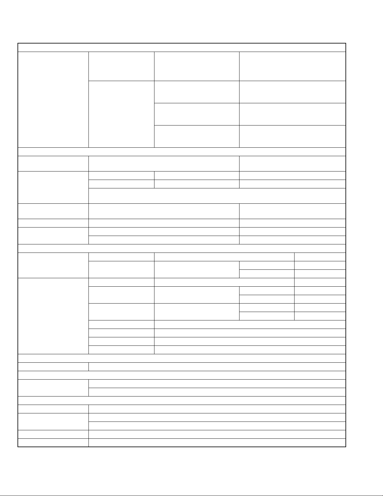
• Alternate check method
Plug the AC line cord directly into the AC outlet. Use an
AC voltmeter having, 1,000
in the following manner. Connect a 1,500
paralleled by a 0.15
exposed metal part and a known good earth ground.
Measure the AC voltage across the resistor with the AC
Ω per volt or more sensitivity
Ω 10W resistor
µF AC-type capacitor between an
voltmeter.
Move the resistor connection to each exposed metal
part, particularly any exposed metal part having a return
path to the chassis, and measure the AC voltage across
the resistor. Now, reverse the plug in the AC outlet and
repeat each measurement. Voltage measured any must
not exceed 0.75 V AC (r.m.s.). This corresponds to 0.5
mA AC (r.m.s.).
AC VOLTMETER
(Having 1000
ohms/volts,
or more sensitivity)
0.15 F AC TYPE
Place this
probe on
1500 10W
Good earth ground
1.2 Warning
(1) This equipment has been designed and manufactured to
meet international safety standards.
(2) It is the legal resp onsibility of the repairer to ensure that
these safety standards are maintained.
(3) Repairs must be made in accordance with the relevant
safety standards.
(4) It is essential that safety critical compone nts are replaced
by approved parts.
(5) If mains voltage selector is provided, check setting for local
voltage.
1.3 Caution Burrs formed during molding may be left over on some parts
of the chassis.
Therefore, pay attention to such burrs in the case of preforming repair of this system.
1.4 Critical parts for safety
In regard with component parts appearing on the silk-screen
printed side (parts side) of the PWB diagrams, the parts that are
printed over with black such as the resistor ( ), diode ( )
and ICP ( ) or identified by the " " mark nearby are critical
for safety. When replacing them, be sure to use the parts of the
same type and rating as specified by the manufacturer.
(This regulation dose not Except the J and C version)
each exposed
metal part.
(No.MB077)1-3
Page 4
1.5 Preventing static electricity
1.5.1 Grounding to prevent damage by static electricity
Electrostatic discharge (ESD), which occurs when static electricity stored in the body, fabric, etc. is discharged, can destroy the laser
diode in the traverse unit (optical pickup). Take care to prevent this when performing repairs.
1.5.2 About the earth processing for the destruction prevention by static electricity
Static electricity in the work area can destroy the optical pickup (laser dio de) in devices such as DVD players.
Be careful to use proper grounding in the area where repairs are being performed.
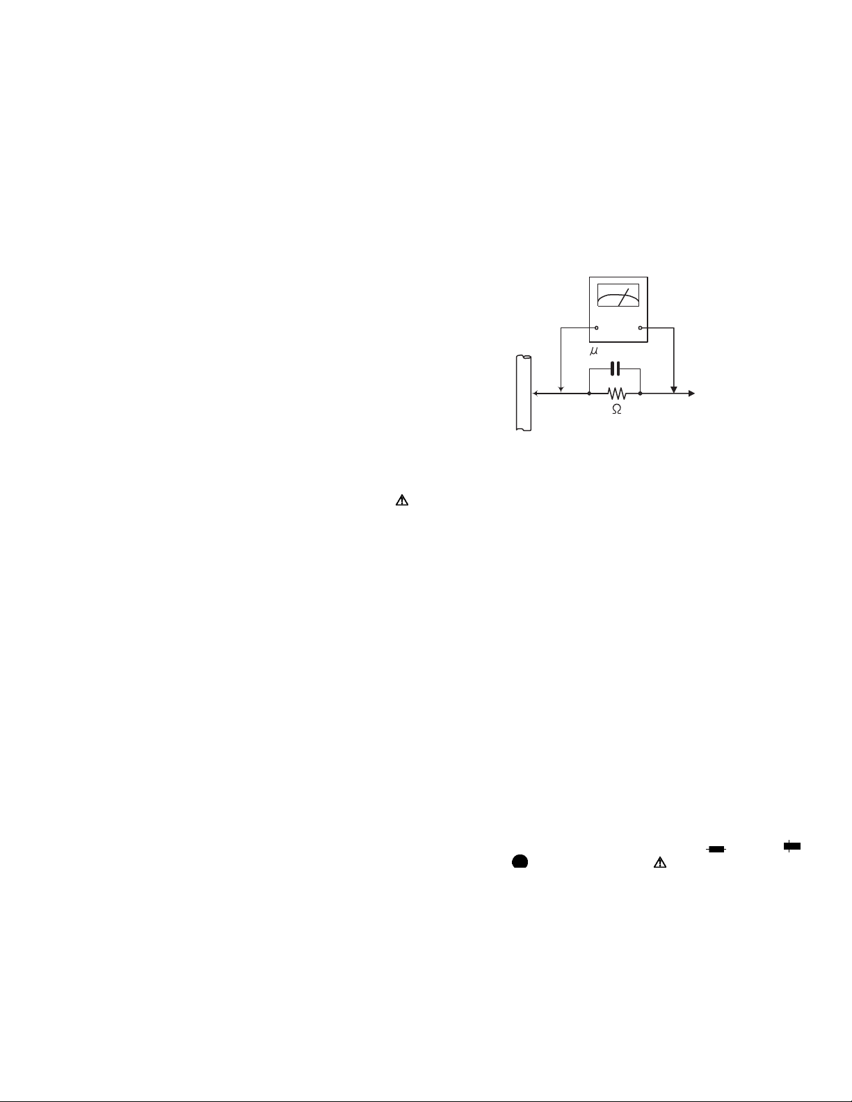
(1) Ground the workbench
Ground the workbench by laying conductive material (such as a conductive sh eet) or an iron plate over it before placing the
traverse unit (optical pickup) on it.
(2) Ground yourself
Use an anti-static wrist strap to release any static electricity built up in your body.
(caption)
Anti-static wrist strap
Conductive material
(conductive sheet) or iron plate
1.5.3 Handling the optical pickup
(1) In order to maintain quality during transport and before installation, both sides of the laser diode on the replacement optical pick-
up are shorted. After replacement, return the shorted parts to their orig inal condition. (Refer to the text.)
(2) Do not use a tester to che ck the condition of the laser diode in the optical pickup. The tester's internal power source can easily
destroy the laser diode.
1.5.4 Handling the traverse unit (optical pickup)
(1) Do not subject the traverse unit (optical pickup) to strong shocks, as it is a sensitive, complex unit.
(2) Remove solder of the short lands on the flexible wire after replacing the optical pickup. For specific details, refer to the replace-
ment procedure in the text. Remove the anti-static pin when replacing the traverse unit.
Be careful not to take too long a time when attaching it to the connector.
(3) Handle the flexible wire carefully as it may break when subjected to strong force.
(4) It is not possible to adjust the semi-fixed resistor that adjusts the laser power. Do not turn it.
1.5.5 Attention when traverse unit is decomposed
*Please refer to "Disassembly method" in the text for the DVD pickup.
• Apply solder to the short circuit points before the flexible wire is disconnected from the connector on the DVD pickup.
(If the flexible wire is disconnected without applying solder, the DVD pickup may be destroyed by static electri city.)
• In the assembly, be sure to remove solder from the short circuit points after connecting the flexible wire.
Flexible wire
Short land sections
DVD mechanism assembly
CN101
DVD servo board
1-4 (No.MB077)
Page 5

SECTION 2
SPECIFIC SERVICE INSTRUCTIONS
This service manual does not describe SPECIFIC SERVICE INSTRUCTIONS.
(No.MB077)1-5
Page 6
SECTION 3
DISASSEMBLY
3.1 Main body section
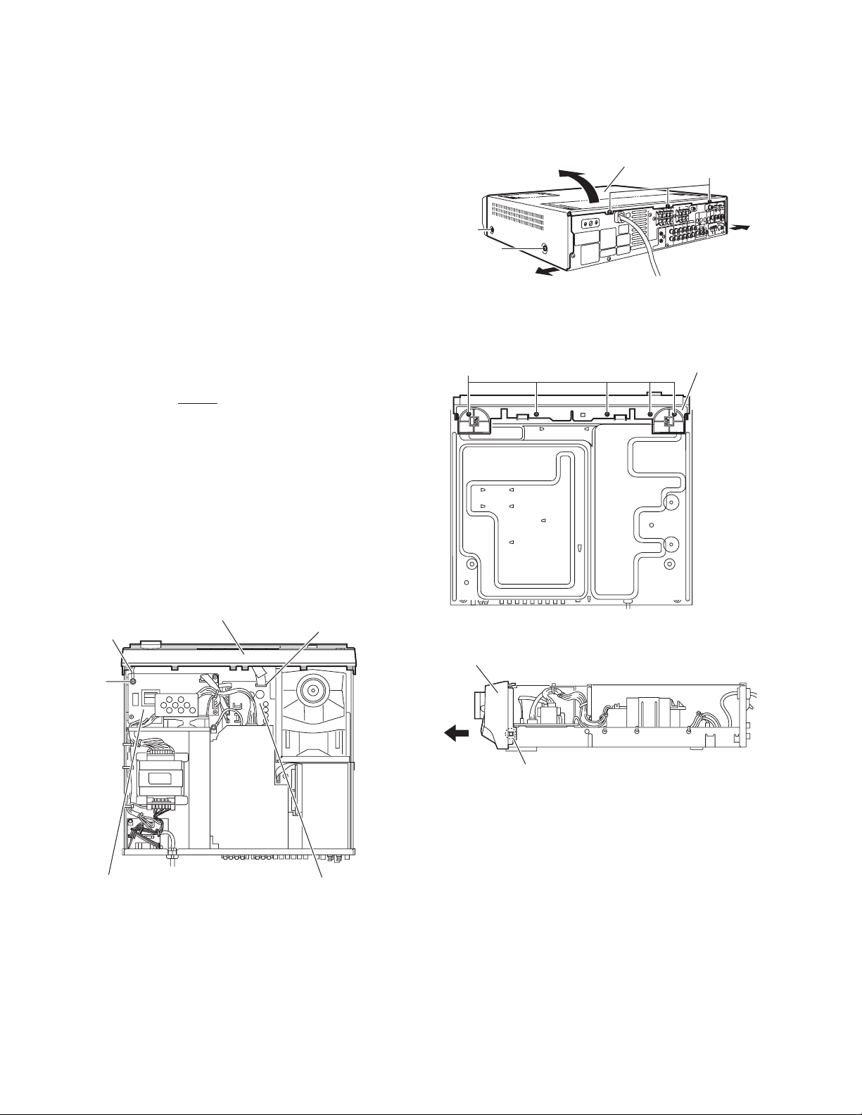
3.1.1 Removing the top cover
(See Fig.1)
(1) From the both sides of the main body, remove the four
screws A attaching the top cover.
(2) From the back side of the main body, remove the three
screws B attaching the top cover.
(3) Remove the top cover in the directi on of the arrow 2 w hile
extending the lower sections of the top cover in the direction of the arrow 1.
3.1.2 Removing the front panel assembly
(See Figs.2 to 4)
• Prior to performing the following procedures, remove the top
cover.
(1) From the top side of the main body, disconnect the card wire
from the connector CN114
(2) Remove the screw C attaching the earth wire and sub
trans. Board. (See Fig.2.)
Reference:
When attaching the screw C, attach the earth wi res together with it.
(3) From the bottom side of the main bo dy, remove the five
screws D attaching the front panel assembly. (See Fig.3.)
(4) From the both side of the main body, release the two joints
a using a flat-bladed screwdriver and remove the front panel assembly in the direction of the arrow. (See Fig.4.)
on the main board. (See Fig.2.)
Ax2
D
Ax2
2
1
Top cover
B
1
Fig.1
Front panel assembly
Earth wire
C
Sub trans board
Front panel assembly
Fig.2
CN114
Main board
Fig.3
Front panel assembly
Joint a
Fig.4
1-6 (No.MB077)
Page 7
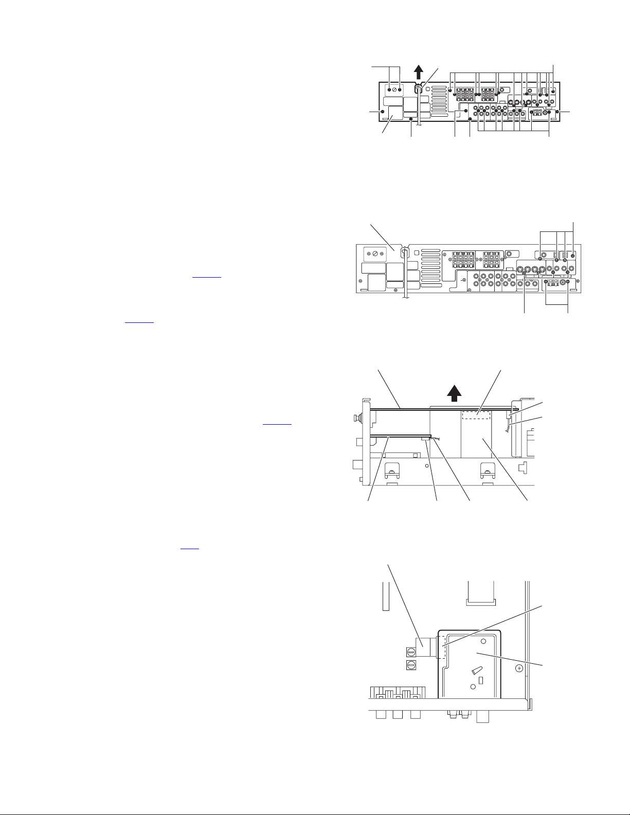
3.1.3 Removing the rear panel
r
(See Fig.5)
• Prior to performing the following p rocedures, remove the top
cover.
(1) From the back side of the main body, remove the strain re-
lief from the rear panel in the direction of the arrow.
(2) Remove the twenty three screws E attaching the each
board to the rear panel.
(3) Remove the four screws F attaching the rear panel.
3.1.4 Removing the DSP board
(See Figs.6 and 7)
• Prior to performing the following p rocedures, remove the top
cover.
(1) From the back side of the main body, remove the four
screws G attaching the DSP board to the rear panel. (See
Fig.6.)
(2) From the top side of the main body, disconnect the DSP
board from the connector CN611
board. (See Fig.7.)
(3) From the left side of the main body, lift the DSP board in the
direction of the arrow and disconnect the card wire from the
connector CN602
(4) Take out the DSP board.
3.1.5 Removing the video jack board
(See Figs.6 and 7)
• Prior to performing the following p rocedures, remove the top
cover and DSP board.
(1) From the back side of the main body, remove the four
screws H attaching the video jack board. (See Fig.6.)
(2) Disconnect the card wire from the connector CN402
video jack board and take out the video jack board. (See
Fig.7.)
on the DSP board. (See Fig.7.)
on the DSP connector
on the
E
F
Rear panel
Rear panel
DSP board
F
Strain relief
FE E
Fig.5
Fig.6
E
F
G
HJ
CN611
CN602
Card wire
3.1.6 Removing the tuner
(See Figs.6 and 8)
• Prior to performing the following p rocedures, remove the top
cover, DSP board and video jack board.
(1) From the back side of the main body, remove the two
screws J attaching the tuner. (See Fig.6.)
(2) From the top side of the main bo dy, disconnect the card
wire from the connector CN1
(3) Take out the tuner.
on the tuner. (See Fig.8.)
Video jack
board
Card wire
CN402
Card wire
Fig.7
Fig.8
DSP connector
board
CN 1
Tune
(No.MB077)1-7
Page 8
3.1.7 Removing the DAC board
(See Fig.9)
• Prior to performing the following procedures, remove the top
cover.
(1) From the top side of the main body, disconnect the DAC
board from the connectors CN911
board.
and CN912 on the main
CN911
DAC board
3.1.8 Removing the amp. board
(See Fig.10)
• Prior to performing the following procedures, remove the top
cover and rear panel.
(1) From the top side of the main body, disconnect the wire
from the connector CN201
(2) Remove the screw K attaching the earth wire to the heat
sink barcket.
(3) Remove the four screws L attaching the amp. board.
(4) Disconnect the conne ctor CN202
(5) Lift the amp. board and disconnect the wire from the con-
nector CN231 on the main board.
(6) Disconnect the parallel wire from the connecto r CN241
the main board and take out the amp. board.
on the amp. board.
on the amp. board.
on
Main board
Heat sink bracket
L
K
CN241
Fig.9
Earth wire
CN231
Fig.10
CN912
CN201
CN202
Amp. board
Main board
3.1.9 Removing the heat sink
(See Fig.11)
• Prior to performing the following procedures, remove the top
cover, rear panel and amp. board.
(1) Remove the screw M attaching the H.sensor board.
(2) Remove the five screws N attaching the IC bracket, heat
sink bracket and heat sink.
1-8 (No.MB077)
Heat sink
Heat sink bracket
IC bracket
N
M
N
Fig.11
H. sensor board
N
Amp. board
Page 9

3.1.10 Removing the power ICs
(See Fig.12)
• Prior to performing the following p rocedures, remove the top
cover, rear panel, amp. board and heat sink.
(1) From the reverse side of the amp. board, remove the sol-
ders from the soldered points b attaching the power ICs to
the amp. board.
3.1.11 Removing the amp. sub(a) board and amp. sub(b) board
(See Fig.13)
• Prior to performing the following p rocedures, remove the top
cover, rear panel and amp. board.
(1) From the forward side of the amp. board, disconnect the
amp. sub(a) board from the connector CN203
board.
(2) Disconnect the amp. sub(b) board from the connector
on the amp. board.
CN204
on the amp
Amp. board
Power ICs solbered points b
Fig.12
Amp. sub (b) board Amp. sub (a) board
3.1.12 Removing the DVD mechanism assembly
(See Fig.14)
• Prior to performing the following p rocedures, remove the top
cover and front panel assembly.
(1) From the top side of the main body, remove the screw P
and two screws Q attaching the DVD mechanism assembly.
Reference:
• When attaching the screw P, attach the thrust spring
together with it.
(2) Disconnect the DVD mechanism assembly from the con-
nectors CN512
(3) Take out the DVD mechanism assembly.
and CN513 on the main board.
Amp. board
CN512
Q
Thrust spring
P
CN203
CN204
Fig.13
CN513
DVD mechanism
assembly
Q
Fig.14
(No.MB077)1-9
Page 10

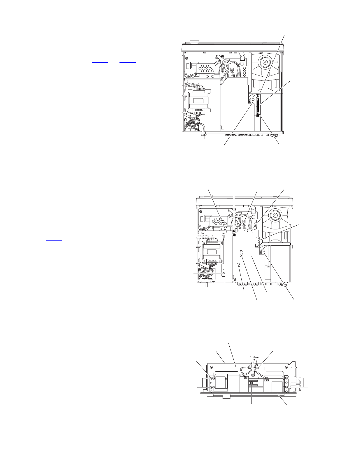
3.1.13 Removing the main board
r
(See Fig.15)
• Prior to performing the following procedures, remove the top
cover, rear panel, DAC board, DSP board, video jack board,
tuner, amp. board and DVD mechanism assembly.
(1) From the top side of the main body, disconnect the fan mo-
tor wire from the connector CN122
(2) Disconnect the card wire from the connector CN125 on the
main board.
(3) Disconnect the wire from the connector CN121
board.
(4) Disconnect the parallel wire from the connecto r CN291
the main board.
(5) Remove the five screws R attaching the main board.
Reference:
Remove the barrier, DSP connector board and amp. connector
board as required.
3.1.14 Removing the sub trans. Board
(See Fig.16)
• Prior to performing the following procedures, remove the top
cover and front panel assembly.
(1) From the top side of the main bo dy, remove the tie band
bundling the wires.
(2) Disconnect the card wire from the connector CN115
sub trans. board.
(3) Disconnect the wire from the connector CN111
trans. board.
(4) Disconnect the wire from the connector CN201 on the amp.
board.
(5) Remove the three screws S attaching the sub trans. board.
(6) From the reverse side of the su b tran s. board, re mo ve the
solders from the soldered points c attaching the wires.
3.1.15 Removing the fan motor
(See Figs.16 and 17)
• Prior to performing the following procedures, remove the top
cover and front panel assembly.
(1) From the top side of the main bo dy, remove the tie band
bundling the wires. (See Fig.16.)
(2) Disconnect the fan motor w ire from the connector CN122
on the main board. (See Fig.16.)
(3) From the front side of the main body, remove the four
screws T attaching the fan motor to the fan bracket. (See
Fig.17.)
(4) Take out the fan motor in the direction of the arrow. (See
Fig.17.)
Reference:
• When attaching the screws T, attach the wire holder and
wire clamp together with them. (See Fig.17.)
• After attaching the fan motor, bundle the wires using the wire
clamp. (See Fig.17.)
on the main board.
on the main
on
on the
on the sub
DSP connecter
board
Barrier
R
CN125 CN121 CN291
Amp. board
CN201
CN122
Fan motor
wire
Tie band
Main board
T
Fan motor
R
Parallel wire
Fig.15
S
S
Fig.16
Main board
Fan motor
Chassis base
CN115
Wire clamp
Amp.
connecto
board
CN122
Fan
motor
wire
Card
wire
Wire
Sub trans.
board
Fan
bracket
S
Soldered
points c
Wire holder
Fan bracket
1-10 (No.MB077)
T
Chassis base
Fig.17
Page 11

3.1.16 Remo ving the voltage selector board
(See Fig.18 and 19)
• Prior to performing the following p rocedures, remove the top
cover.
(1) From the back side of the main body, remove the two
screws U attaching the voltage board. (See Fig.18)
(2) Disconnect the wires from the connectors CN103
CN104 on the voltage selector board. (See Fig.19)
(3) Remove the solders from the soldered sections d on the
voltage selector board and remove the wires of the voltage
selector board. (See Fig.19)
(4) Take out the voltage selector board.
and
U
CN103
Rear panel
Fig.18
Voltage selector
board
Soldered points d
CN104
Tie bands
Fig.19
(No.MB077)1-11
Page 12

3.1.17 Removing the power board
(See Fig.20)
• Prior to performing the following procedures, remove the top
cover.
(1) From the top side of the main body, disconnect the wire
from the connector CN101
Reference:
Remove the tie bands as required.
(2) Remove the solders from the soldered points e attaching
the power cord.
(3) Remove the two screws V attaching the power board.
(4) From the reverse side of the power board, remove the sol-
ders from the soldered point f attaching the wires.
3.1.18 Removing the power trans. former
(See Figs.20 and 21)
• Prior to performing the following procedures, remove the top
cover.
(1) From the top side of the main body, remove the tie bands
and wire clamps bundling the wires. (See Fig.21.)
(2) Disconnect the wire from the connector CN121
board. (See Fig.21.)
(3) Disconnect the wires from the connector CN111
trans. board. (See Fog.21.)
(4) Remove the two screws V attaching the power board and
then turn over the power board. (See Fig.20.)
(5) Remove the solders from the soldered points f attaching
the wires. (See Fig.20.)
(6) Remove the four screws W attaching the power trans.
former. (See Fig.20.)
(7) Take out the power trans. former.
on the power board.
on the main
on the sub
Power board
CN101
Main board
Tie bands
CN111
Power cord
V
Power trans. former
Fig.20
X
Soldered points e
Soldered points f
V
Tie bands
WW
Wire clamps
Sub
trans
board
X
3.1.19 Removing the H.P board
(See Fig.21)
• Prior to performing the following procedures, remove the top
cover and front panel assembly.
(1) From the top side of the main body, disconnect the parallel
wire from the connector CN291
(2) Remove the three screws X attaching the sub trans. board.
Reference:
It is not necessary to remove the wire from the sub trans. board.
(3) Remove the screw Y attaching the H.P board while lifting
the sub trans. board slightly.
on the main board.
CN121 CN291
X
Tie bands
Fig.21
Y
H.P
board
1-12 (No.MB077)
Page 13

3.2 Front panel assembly section
3.2.1 Removing the FL board
(See Figs.22 and 23)
• Prior to performing the following p rocedures, remove the top
cover and front panel assembly.
(1) From the front side of the front panel assembly, pull out the
volume knob assembly in the direction of the arrow. (See
Fig.22.)
(2) From the back side of the front panel assembly, remove the
eight screws Z attaching the FL board. (See Fig.23.)
(3) Disconnect the wire from the connector CN703
board while lifting the FL board slightly. (See Fig.23.)
(4) Remove the solders from the soldered points g and h at-
taching the parallel wires while lifting the FL board. (See
Fig.23.)
(5) Take out the FL board from the front panel assembly.
Reference:
Remove the parallel wires as required.
on the FL
Front panel
assembly
Volume knob assembly
Fig.22
Front panel
FL board Wire
Soldered point g
Fig.23
Z
Soldered point h
CN703
(No.MB077)1-13
Page 14

3.2.2 Removing the control board
(See Fig.24)
• Prior to performing the following procedures, remove the top
cover, front panel assembly and FL board.
Reference:
It is not necessary to remove the parallel wires from the FL
board.
(1) Remove the three screws AA attaching the control board.
(2) Remove the solders from the solde red points i attaching
the parallel wire while lifting the control board.
Reference:
Remove the parallel wire as required.
Control board
AA AB
Indicator board
Soldered point i
FL board
Soldered point j
Fig.24
Lens holder
3.2.3 Removing the indicator board
(See Fig.24 and 25)
• Prior to performing the following procedures, remove the top
cover and front panel assembly.
(1) From the back side of the front panel assembly, remove the
two screws AB attaching the lens holder. (See Fig.24.)
(2) Remove the solders from the soldered points j on the FL
board attaching the parallel wire. (See Fig.24.)
(3) Remove the solders from the soldered points k on the pow-
er switch board attaching the parallel wire. (See Fig.25.)
Reference:
Remove the parallel wires as required.
3.2.4 Removing the power switch board
(See Fig.25)
• Prior to performing the following procedures, remove the top
cover and front panel assembly.
(1) From the back side of the front panel assembly, remove the
two screws AC attaching the power switch board.
(2) Remove the solders from the soldered points k on the pow-
er switch board attaching the parallel wire.
Reference:
Remove the parallel wire as required.
3.2.5 Removing the speaker SW. board
(See Fig.25)
• Prior to performing the following procedures, remove the top
cover and front panel assembly.
(1) From the back side of the front panel assembly, remove the
three screws AD attaching the speaker SW. board.
(2) Disconnect the wire from the con nector CN703
board.
on the FL
FL board
Power switch
CN703
Speaker SW. board
Fig.25
board
AD
AC
Soldered
point k
1-14 (No.MB077)
Page 15

3.3 DVD mechanism section
• Remove the top cover.
• Remove the front panel assembly.
• Remove the DVD mechanism assembly.
3.3.1 Removing the tray
(See Figs.1 and 2)
(1) From the left side of the DVD mechanism a ssembly, push
the slide cam in the direction of the arrow 1 and then pull
out the tray in the direction of the arrow 2. (See Fig.1.)
(2) Push the tray stoppers a in the direction of the arrow 3, pull
out the tray in the direction of the arrow 4. (See Fig.2.)
3.3.2 Attaching the tray
(See Fig.2)
When attaching the tray, insert the tray to the rail of the DVD
mechanism assembly and then push th e tray in the DVD mechanism assembly.
Tr ay
2
1
Slide cam
Fig.1
3.3.3 Removing the tray
(See Fig.3)
(1) From the bottom side of the DVD mechanism assembly,
disconnect the card wires from the connectors CN201
on the DVD servo board.
CN202
Caution:
Be sure to solder the short land sections b on the flexible
wire before disconnecting the flexible wire from connector CN101
If the flexible wire is disconnected without attaching solder, the DVD pickup unit may be destroyed by static
electricity.
(2) Release the locks of the connector CN101
vo board in the direction of the arrow 1, disconnect the flexible wire.
Caution:
In the assembly, be sure to remove solders from the
short land sections b after connecting the flexible wire to
the connector CN101
(3) While pushing the claws c of the DVD mechanism assem-
bly in the direction of the arrow 2, remove the DVD servo
board in an upward direction.
on the DVD servo board.
on the DVD ser-
on the DVD servo board.
and
Card wire
CN201
Claw c
Tray stoppers
3
DVD mechanism assembly
Fig.2
Flexible wire
Short land sections b
DVD mechanism assembly
11
2 22
a
4
Tr ay
Card wire
CN202
Claw c
DVD servo board
CN101
Fig.3
(No.MB077)1-15
Page 16
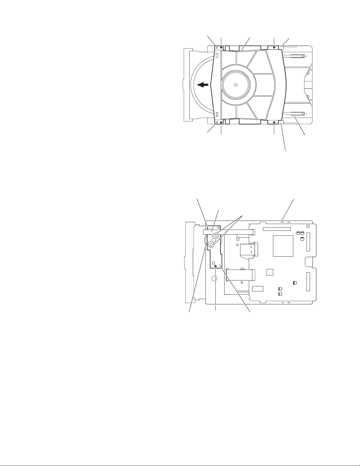
3.3.4 Removing the clamper base
(See Fig.4)
(1) From the top side of the DVD mechanism assembly, re-
move the four screws A attaching the clamper base.
(2) Remove the clamper base from the bosse s d of the loadi ng
base in an upward direction, remove the clamper base
from the sections e while sliding it in the direction of the arrow.
Boss d
Clamper base
AA
Section e
3.3.5 Removing the tray drive board
(See Fig.5)
• Remove the clamper base.
(1) From the bottom side of the DVD mechanism assembly,
disconnect the card wire from the connector on the tray
drive board.
(2) Remove the solders from the soldered sections f on the
tray drive board.
(3) Remove the screw B attaching th e tray drive board to the
DVD mechanism assembly.
Boss d
Connector
A A
Fig.4
Card wire
Soldered
sections f
Loading base
Section e
DVD mechanism assembly
1-16 (No.MB077)
Motor
B
Tray drive board
Fig.5
Page 17

3.3.6 Removing the motor
(See Fig.6)
• Remove the clamper base.
• Remove the tray drive board.
(1) From the top side of the DVD mechan ism assembly, re-
move the belt of the pulley gear.
Note:
Take care not to attach grease on the belt.
(2) Remove the screw C attaching the motor to the DVD mech-
anism assembly.
3.3.7 Removing the DVD traverse mechanism assembly
(See Figs.7)
• Remove the DVD servo board.
• Remove the clamper base.
(1) From the top side of the DVD mechan ism assembly, re-
move the four screws D attaching the DVD traverse mechanism assembly to the loading base.
(2) Take out the DVD traverse mechanism assembly from the
loading base.
Pulley gear
DVD mechanism assembly
Belt
C
Motor
Fig.6
DVD traverse mechanism assembly
D D
DD
Fig.7
Loading base
(No.MB077)1-17
Page 18

3.3.8 Removing the DVD pickup unit
(See Figs.8 to 10)
• Remove the DVD servo board.
• Remove the clamper base.
• Remove the DVD traverse mechanism assembly.
(1) From the top side of the DVD traverse mechanism assem-
bly, remove the screw E attaching the plate and torsion
spring. (See Fig.8.)
(2) Remove the shaft from the section g and then remove the
shaft from the section h. (See Fig.9.)
(3) Disengage the section i of the DVD pickup unit and then re-
move the DVD pickup unit with the shaft. (See Fig.9.)
(4) Pull the shaft out of the DVD pickup unit. (See Fig.10.)
(5) Remove the two screws F attaching the SW. actuator. (See
Fig.10.)
3.3.9 Attaching the DVD pickup unit
(See Figs.8, 10 to 12)
Reference:
Refer to the explanation of "Removing the DVD pickup unit" on
the preceding page.
(1) Attach the SW. actuator and shaft to the DVD p ickup unit.
(See Fig.10.)
(2) Engage the section i of the DVD pickup unit to the shaft of
the DVD traverse mechanism assembly first, and set the
both ends of the shaft of the DVD pickup unit in the sections
g and h of the DVD traverse mechanism assembly. (See
Fig.11.)
(3) Slide the DVD pickup unit all the way in the direction of the
arrow. (See Fig.12.)
(4) Mesh the lead screw to the section j of DVD pickup unit and
then set the end of the lead screw to the section k. (See
Fig.12.)
(5) Attach the torsion spring. (See Fig.8.)
(6) Attach the plate. (See Fig.8.)
DVD pickup unit
Section i
Section i
SW. actuator
Shaft
Section h
Shaft
Section g
Fig.9
F
DVD pickup unit
Fig.10
DVD pickup unit
E
Plate
Torsion spring
DVD traverse mechanism assembly
Fig.8
DVD pickup unit
Shaft
Section g
DVD pickup unit
Section h
DVD traverse mechanism assembly
Fig.11
Section k
Section j
Lead screw
1-18 (No.MB077)
Fig.12
Page 19

3.3.10 Remo ving the spindle motor board
r
(See Figs.13 and 14)
• Remove the DVD servo board.
• Remove the clamper base.
• Remove the DVD traverse mechanism assembly.
(1) From the top side of the DVD traverse mechanism assem-
bly, remove the feed motor wire that is soldered to the spindle motor board. (See Fig.13.)
(2) From the bottom side of the DVD traverse mechanism as-
sembly, remove the three screws G attaching the spindle
motor board. (See Fig.14.)
Spindle motor board
Remove the solders.
Feed moto
wire
DVD traverse mechanism assembly
Fig.13
G
DVD traverse mechanism assembly
Fig.14
G
(No.MB077)1-19
Page 20

3.3.11 Removing the feed motor
r
(See Figs.15 to 17)
• Remove the DVD servo board.
• Remove the clamper base.
• Remove the DVD traverse mechanism assembly.
(1) From the top side of the DVD traverse mechanism assem-
bly, remove the feed motor wire that is soldered to the spindle motor board. (See Fig.15.)
(2) Remove the two screws H attaching the feed holder as-
sembly and then take out the feed holder assembly. (See
Fig.15.)
(3) Remove the screw J attaching the thrust spring. (See
Fig.16.)
(4) Remove the feed gear and lead screw in the direction of the
arrow. (See Fig.16.)
(5) Remove the two screws K attaching the feed motor. (See
Fig.17.)
Spindle motor board
DVD traverse mechanism assembly
Fig.15
Feed holder assembly
Remove the solders.
Feed holde
assembly
H
Feed motor
wire
Feed motor
H
Lead screw
Feed motor
Feed gear
Thrust spring
J
Fig.16
Feed holder assembly
1-20 (No.MB077)
K
Fig.17
Page 21

SECTION 4
C
ADJUSTMENT
4.1 TEST mode (See Fig.1)
(1) Before executing the test mode, press the DVD button on the remote control unit to set the main unit to the DVD mode.
(2) This model is provided with a test mode for use in production control, servicing and repair.
(3) The test mode includes the followin g four submodes, which are switched over every time the CHOICE button on the remote
control unit is pressed.
(4) The test mode is exited when the power is switched on or off.
(5) While holding the STOP and DVD buttons on the main unit, plug the power cord into the wall power outlet.
(6) The opening screen showing the version number is displayed.
The FL display shows "TEST ". : Destination type symbol.
DVD button
(Initialization)
STANDBY/ON button
DVD button
(TEST mode)
HOICE button
(TEST mode)
OPEN/CLOSE button
(TEST mode)
STOP button
(TEST mode)
FL display
Fig.1
(1) Press the button once: Microcomputer version display mode / The FL display shows the version numbers of the microcomputers
in use.
Displayed information: [System MICON] [Front-end (FE) MICON] [Back-end (BE) MICON]
(2) Press the button twice: Display check mode / All FL and LED segments light up.
(3) Press the button three times: Mechanism check mode / The FL display shows "CHECK".
(4) Press the button four times: Front-end check mode / The FL display shows "EXPERT".
(No.MB077)1-21
Page 22

SECTION 5
TROUBLESHOOTING
This service manual does not describe TROUBLE SHOOTING.
1-22 (No.MB077)
Page 23

(No.MB077)1-23
Page 24

VICTOR COMPANY OF JAPAN, LIMITED
AV & MULTIMEDIA COMPANY AUDIO/VIDEO SYSTEMS CATEGORY 10-1,1chome,Ohwatari-machi,Maebashi-city,371-8543,Japan
(No.MB077)
Printed in Japan
WPC
 Loading...