

Page 1
For Customer Use:
Enter below the Model No. and Serial
No. which are located either on the rear,
bottom or side of the cabinet. Retain this
information for future reference.
Model No.
Serial No.
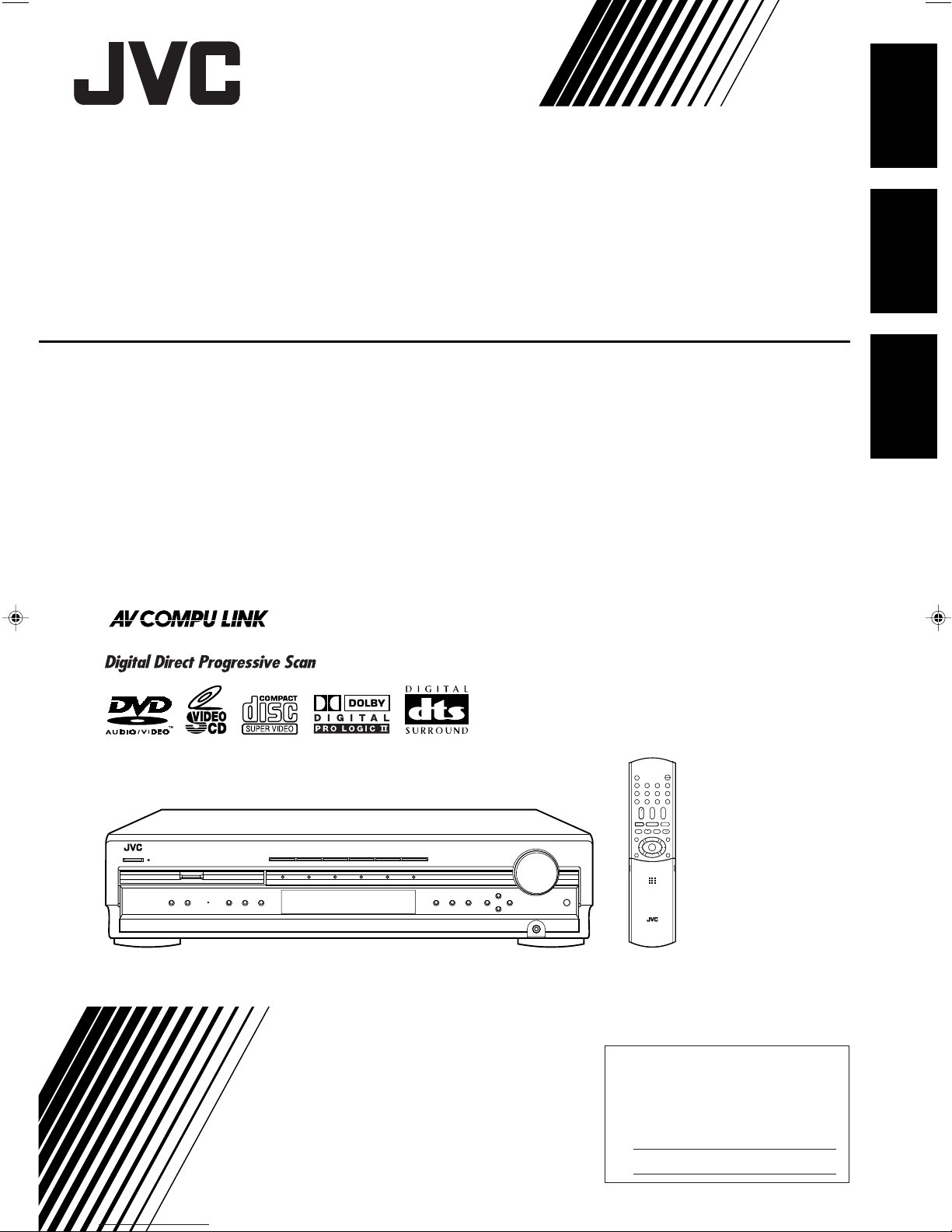
HOME CINEMA DVD-AUDIO/VIDEO CONTROL CENTER
DVD/SUPER VCD/VCD/CD
COMPACT
SUPER VIDEO
RX-DV31 HOME THEATER DVD-AUDIO/VIDEO RECEIVER
CENTRO DE CONTROL DE CINE EN CASA CON REPRODUCTOR DE DVD AUDIO/VIDEO
CENTRO DE CONTROLE DE AUDIO E VIDEO DO DVD HOME CINEMA
RX-DV31SL
English
Español
Português
INSTRUCTIONS
MANUAL DE INSTRUCCIONES
INSTRUÇÕES
LVT1001-014A
[UW]
Page 2
Warnings, Cautions, and Others
Avisos, precauciones y otras notas
Advertêcias, precauções e outras notas
Caution — STANDBY/ON button!
Disconnect the mains plug to shut the power off completely. The
STANDBY/ON button in any position does not disconnect the
mains line. The power can be remote controlled.
Precaución — Botón STANDBY/ON!
Para desactivar la alimentación completamente, desenchufe el
cable de alimentación de CA.
La línea de la red no se desconecta en ninguna de las
posiciones del botón STANDBY/ON.
La alimentación puede ser controlada a distancia.
Precaução — Botão STANDBY/ON!
Desconectar o cabo de alimentação para desligar a alimentação
por completo. Qualquer que seja a posição de ajuste do
botão STANDBY/ON, a alimentação não é completamente
cortada. A alimentação pode ser controlada remotamente.
CAUTION
To reduce the risk of electrical shocks, fire, etc.:
1. Do not remove screws, covers or cabinet.
2. Do not expose this appliance to rain or moisture.
PRECAUCIÓN
Para reducir el riesgo de descargas eléctricas, fuego, etc.:
1. No quitar los tomillos, tapas o caja.
2. No exponer el aparato a la lluvia ni a la húmedad.
ATENÇÃO
Para reduzir riscos de choques eléctricos, incêndio, etc.:
1. Não retire parafusos nem desmonte as tampas ou o
gabinete.
2. Não exponha este aparelho à chuva nem à umidade.
G-1
Page 3

CAUTION
• Do not block the ventilation openings or holes.
(If the ventilation openings or holes are blocked by a newspaper or cloth, etc., the heat may not be able to get
out.)
• Do not place any naked flame sources, such as lighted candles, on the apparatus.
• When discarding batteries, environmental problems must be considered and local rules or laws governing the
disposal of these batteries must be followed strictly.
• Do not expose this apparatus to rain, moisture, dripping or splashing and that no objects filled with liquids,
such as vases, shall be placed on the apparatus.
PRECAUCIÓN
• No obstruya las rendijas o los orificios de ventilación.
(Si las rendijas o los orificios de ventilación quedan tapados con un periódico, un trozo de tela, etc., no se
podrá disipar el calor).
• No ponga sobre el aparato ninguna llama al descubierto, como velas encendidas.
• Cuando tenga que descartar las pilas, tenga en cuenta los problemas ambientales y observe estrictamente los
reglamentos o las leyes locales sobre disposición de las pilas.
• No exponga este aparato a la lluvia, humedad, goteos o salpicaduras. Tampoco ponga recipientes conteniendo
líquidos, como floreros, encima del aparato.
PRECAUÇÃO
• Não obstrua as aberturas e orifícios de ventilação. (Se os orifícios ou aberturas de ventilação estiverem
obstruídos por qualquer papel ou tecido, não haverá circulação do ar quente.)
• Não coloque nenhum objeto com chamas, como velas acesas, sobre o aparelho.
• Ao descartar as baterias, leve em consideração os problemas que possam ser causados ao meio ambiente e
os regulamentos e leis locais e governamentais sobre recolhimento dessas baterias devem ser rigorosamente
seguidos.
• Não exponha este aparelho à chuva, umidade, pingos ou esguichos de água, nem coloque em cima do
mesmo qualquer tipo de recipiente que contenha líquidos, como por exemplo vasos.
G-2
Page 4
IMPORTANT FOR LASER PRODUCTS/
IMPORTANTE PARA LOS PRODUCTOS LÁSER/
IMPORTANTE PARA PRODUCTOS LASER
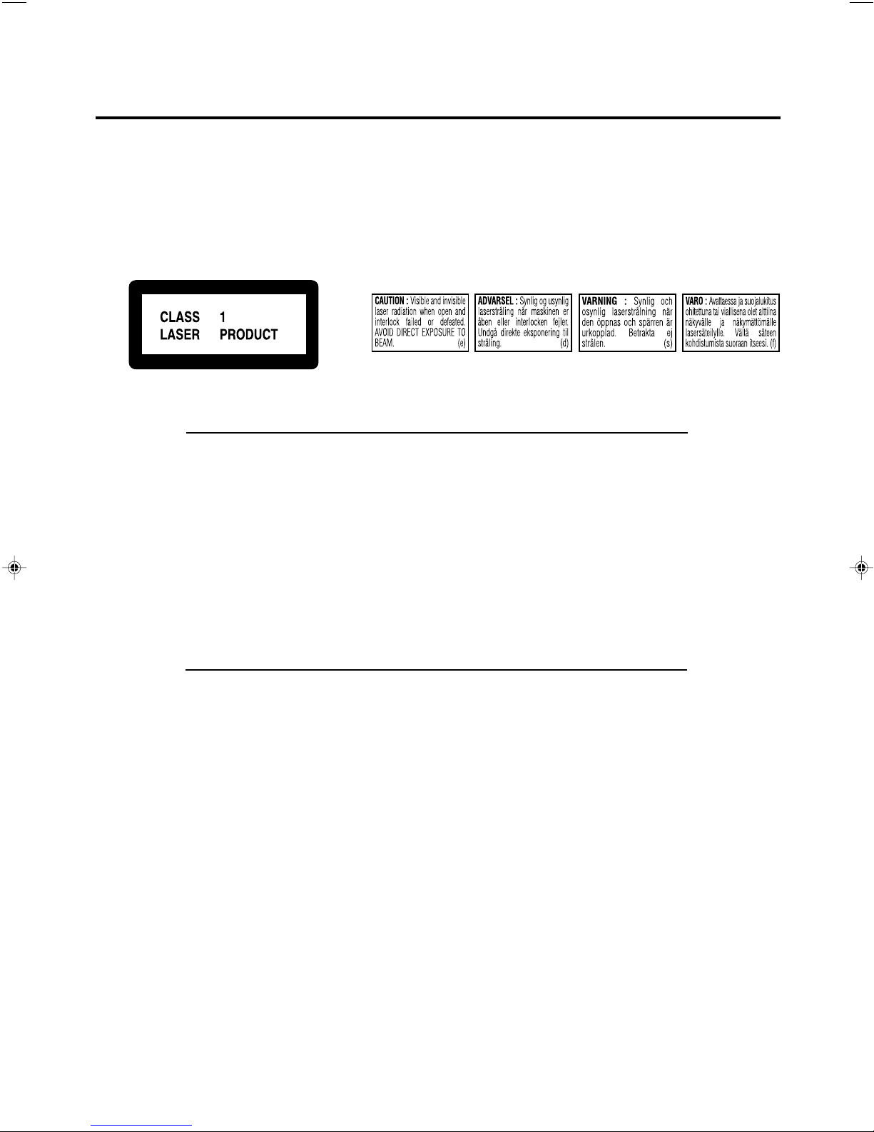
REPRODUCTION OF LABELS/REPRODUCCIÓN DE ETIQUETAS/REPRODUÇÃO, DE ETIQUETAS
1 CLASSIFICATION LABEL, PLACED ON EXTERIOR SURFACE
1 ETIQUETA DE CLASIFICACION, PROVISTA SOBRE LA
SUPERFICIE EXTERIOR
1 ETIQUETA DE CLASSIFICACAO, COLOCADA EM SUPERFICIE
EXTERNA
1. CLASS 1 LASER PRODUCT
2. CAUTION: Visible and invisible laser radiation when open and interlock failed or defeated. Avoid
direct exposure to beam.
3. CAUTION: Do not open the top cover. There are no user serviceable parts inside the Unit; leave all
serv-icing to qualified service personnel.
1. PRODUCT LASER CLASE 1
2. PRECAUCIÓN: Radiación láser visible e invisible al abrir, o al fallar o ignorar los cierres de
seguridad. Evite la exposición directa a los haces.
3. PRECAUCIÓN: No abra la tapa superior. En el interior de la unidad no existen piezas reparables
por el usuario; deje todo servicio técnico en manos de personal calificado.
2 WARNING LABEL, PLACED INSIDE THE UNIT
2 ETIQUETA DE ADVERTENCIA, PEGADA EN EL INTERIOR DE
LA UNIDAD
2 ETIQUETA DE ADVERTÊNCIA LOCALIZADA NA PARTE
INTERNA DA UNIDADE
1. PRODUCTO LASER CLASSE 1
2. PRECAUÇÃO: Radiação laser visível e invisível quando aberto e bloqueio falhou ou avariou. Evite
exposinao direta ao feixe dos raios.
3. PRECAUÇÃO: Não abra a caixa do aparelho. Não existem peças reparáveis pelo usuário na parte
interna da unidade. Solicite assistência técnica somente a pessoal técnico qualificado.
G-3
Page 5
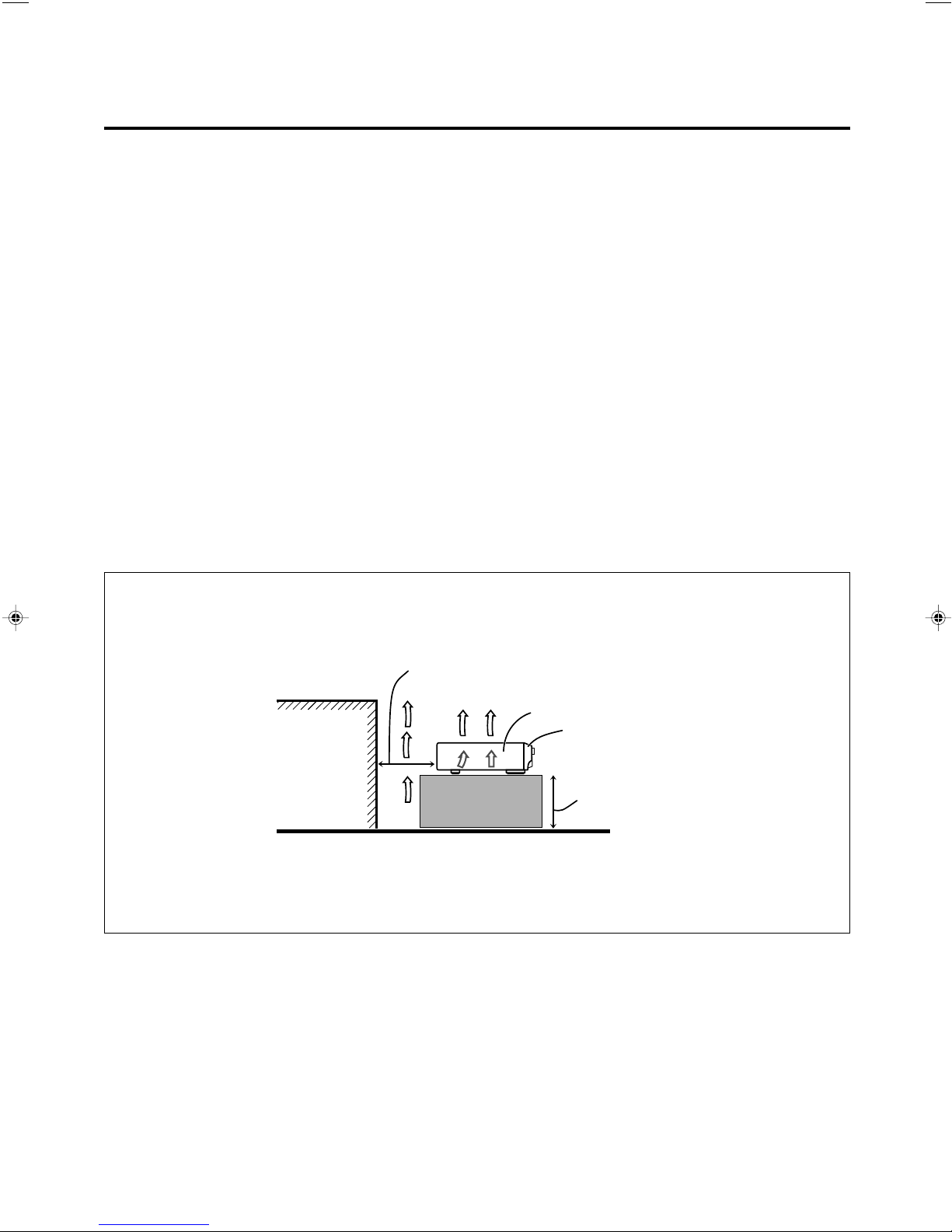
Caution: Proper Ventilation
To avoide risk of electric shock and fire and to protect from damage.
Locate the apparatus as follows:
Front: No obstructions open spacing.
Sides: No obstructions in 10 cm from the sides.
Top: No obstructions in 10 cm from the top.
Back: No obstructions in 15 cm from the back
Bottom: No obstructions, place on the level surface.
In addition, maintain the best possible air circulation as illustrated.
Precaución: Ventilación Adecuada
Para evitar el riesgo de choque eléctrico e incendio y para proteger el
aparato contra daños.
Ubique el aparato de la siguiente manera:
Frente: Espacio abierto sin obstrucciones
Lados: 10 cm sin obstrucciones a los lados
Parte superior: 10 cm sin obstrucciones en la parte superior
Parte trasera: 15 cm sin obstrucciones en la parte trasera
Fondo: Sin obstrucciones, colóquelo sobre una superficie
nivelada
Además, mantenga la mejor circulación de aire posible como se ilustra.
Precaução: ventilação apropriada
Para prevenir o risco de choque elétrico ou incêndio e para proteger
o aparelho contra danos.
Localize-o da seguinte maneira:
Frente: Espaço aberto, sem obstruções
Lados: Espaço de 10 cm sem obstruções nos lados
Topo: Espaço de 10 cm sem obstruções acima
Atrás: Espaço de 15 cm sem obstruções atrás
Parte inferior: Sem obstruções. Coloque o aparelho em superfície
nivelada.
Mantenha, além disso, a maior circulação de ar possível, como indica
a ilustração.
Wall or obstructions/
Pared u obstrucciones/
Parede ou obstáculo
Spacing 15 cm or more/
Espacio de 15 cm o más/
Espaço de 15 cm ou mais
RX-DV31SL
Front/
Frente/
Frente
Stand height 15 cm or more/
Allura del soporte 15 cm o más/
Base com altura de 15 cm ou mais
Floor/
Piso/
Piso
G-4
Page 6
Before Installation
VOLTAGE
SELECTOR
110V
127V
230-240V
220V
VOLTAGE
SELECTOR
110V
127V
230-240V
220V
English
Precautions
General Precautions
• DO NOT insert any metal object into the unit.
• DO NOT disassemble the unit or remove screws, covers, or
cabinet.
• DO NOT expose the unit to rain or moisture.
Locations
• Install the unit in a location that is level and protected from
moisture.
• The temperature around the unit must be between 5˚C and
35˚C.
• Make sure there is good ventilation around the unit. Poor
ventilation could cause overheating and damage the unit.
Handling the unit
• DO NOT touch the power cord with wet hands.
• DO NOT pull on the power cord to unplug it. When
unplugging the cord, always grasp the plug so as not to
damage the cord.
• Keep the power cord away from the connecting cords and
the antenna. The power cord may cause noise or screen
interference. It is recommended to use a coaxial cable for
antenna connection, since it is well-shielded against
interference.
• When a power failure occurs, or when you unplug the
power cord, the preset settings such as preset FM or AM
channels and sound adjustments may be erased in a few
days.
Checking the Supplied Accessories
Check to be sure you have all of the following supplied
accessories.
The number in the parentheses indicates the quantity of the
pieces supplied.
• Remote control (1)
• Batteries (2)
• AM loop antenna (1)
• FM antenna (1)
• Composite video cord (1)
• AC plug adaptor (1)
If anything is missing, contact your dealer immediately.
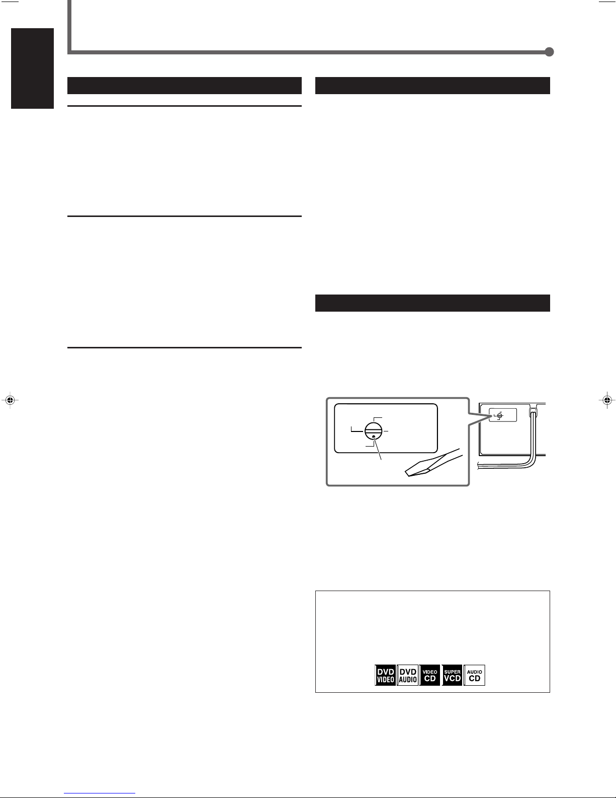
Adjusting the Voltage Selector
Before connections, always do the following first if necessary.
Select the correct voltage in VOLTAGE SELECTOR on the
rear by using a screw driver.
Check to be sure if the voltage mark is set to the voltage for
the area where you use this unit.
Voltage mark
1
• Times given for various operations are for reference only.
Actual time will vary somewhat.
• The following mark is used in this manual to indicate
available disc types for the operations explained in each
section. Unavailable disc types are shown in halftone
color.
Page 7

Table of Contents
Parts Identification ...................................... 3
Front Panel ....................................................................... 3
Remote Control ................................................................ 4
Rear Panel ........................................................................ 5
Getting Started ........................................... 6
Connecting the AM and FM Antennas ............................. 6
Connecting the Speakers ................................................. 7
Connecting Audio/Video Components ............................. 8
7 About connecting cords ............................................ 8
7 Setting the color system ............................................ 8
7 TV connection............................................................ 9
7 DBS tuner connection ............................................... 9
7 VCR connection....................................................... 10
7 Cassette deck/CD recorder connection .................. 10
7 Digital connection.................................................... 11
Putting Batteries in the Remote Control ......................... 11
Basic Operations ....................................... 12
Turning On the Power ..................................................... 12
Selecting the Source to Play .......................................... 12
Adjusting the Volume ..................................................... 12
7 Listening with headphones ..................................... 13
Selecting the Front Speakers ......................................... 13
Changing the Source Name ........................................... 13
Turning Off the Sound Temporarily ................................. 14
Changing the Display Brightness .................................. 14
Turning Off the Power with the Sleep Timer ................... 14
Selecting the Analog or Digital Input Mode ................... 14
7 Changing the digital input mode manually
—for DVD VIDEO only ............................................. 15
Attenuating the Input Signal ........................................... 15
Changing the Scanning Mode ....................................... 16
Activating the Recording Mode ..................................... 16
Basic DVD Player Operations ...................... 17
Tuner Operations ....................................... 20
Setting the AM Tuner Interval Spacing ........................... 20
Tuning in to Stations Manually ........................................ 20
Using Preset Tuning ....................................................... 21
7 Storing preset stations ............................................. 21
7 Tuning in to a preset station .................................... 22
Selecting the FM Reception Mode ................................. 22
Basic Settings ........................................... 23
Setting Speakers Quickly ............................................... 23
Setting Basic Items ........................................................ 24
7 Speaker information ................................................ 25
7 Speaker distance .................................................... 25
7 Crossover frequency ............................................... 26
7 Low frequency effect attenuator .............................. 26
7 Dynamic range compression .................................. 26
7 Digital input (DIGITAL IN) terminals ........................ 27
7 Auto surround .......................................................... 27
7 Video output mode .................................................. 27
Sound Adjustments.................................... 28
7 Front speaker output balance ................................. 28
7 Tone ......................................................................... 29
7 Speaker output levels.............................................. 29
7 DAP effect level ....................................................... 29
7 Subwoofer audio position ........................................ 29
Creating Realistic Sound Fields ................... 30
Activating Surround Mode ............................................. 32
Selecting Surround Modes ............................................. 32
Adjusting Surround Mode Using Remote Control .......... 33
DVD Player Operations .............................. 34
Disc Information ............................................................. 34
About the On-screen Bar ............................................... 36
Basic Operation through the On-screen Bar.................. 37
Changing the Time Indication ........................................ 37
Locating a Desired Scene from the Disc Menu ............. 38
Selecting a View Angle .................................................. 39
Selecting the Subtitle Language .................................... 39
Selecting the Audio Language ....................................... 40
Selecting the Audio Channel .......................................... 40
Playing from a Specified Position on a Disc .................. 41
7 Locating a desired title/group ................................. 41
7 Locating a desired chapter/track ............................ 42
7 Locating a desired position ..................................... 42
Special Picture Playback ............................................... 43
7 Still picture and frame-by-frame playback .............. 43
7 Playing back in slow-motion .................................... 43
7 Selecting browsable still pictures
recorded on DVD AUDIO ........................................ 43
7 Zooming in............................................................... 44
7 Playing back a bonus group ................................... 44
Changing the VFP Setting .............................................. 45
Program Playback .......................................................... 46
Random Playback .......................................................... 47
Repeat Playback ............................................................ 47
MP3 Disc Playback .................................... 49
Basic Operations ............................................................ 49
Operations through the MP3 CONTROL Screen............ 50
Repeat Playback ............................................................ 50
JPEG Disc Playback ................................... 51
Slide-show Playback ...................................................... 51
Operations through the JPEG CONTROL Screen .......... 52
Repeat Playback ............................................................ 52
Choice Menu Operations............................. 53
7 Language selection menu—LANGUAGE ............... 55
7 Picture setting menu—PICTURE ............................. 55
7 Audio selection menu—AUDIO ............................... 56
• Language code list .............................................. 56
7 Speaker setting menu—SPK. SETTING .................. 57
7 Other setting menu—OTHERS ................................ 58
Restricting Playback by Parental Lock .......................... 59
7 Setting Parental Lock .............................................. 59
7 Changing the Parental Lock setting ........................ 60
7 Releasing Parental Lock temporarily ....................... 60
• Country/Area codes list for Parental Lock ........... 61
Glossary for DVD Player ............................ 62
AV COMPU LINK Remote Control System .... 63
Operating JVC’s Audio/Video Components ... 65
Operating Audio Components ....................................... 65
Operating Video Components ....................................... 66
Operating Other Manufacturers’
Equipment ............................................ 67
Changing the Preset Signal Codes ................................ 67
Maintenance ............................................. 70
Troubleshooting ......................................... 71
Specifications............................................ 74
English
2
Page 8
Parts Identification
PL
DIGITAL
1
3
RX-DV31 HOME CINEMA DVD-AUDIO/VIDEO CONTROL CENTER
MASTER VOLUME
DVD/SUPER VCD/VCD/CD
DVD AUDIO
INPUT ATT.
INPUT
ANALOG/DIGITAL
SETTING ADJUST MEMORY
ON/OFF
SURROUND
MODE1
SPEAKERS
2
FM/AMTAPE/CDR
SOURCE NAME
TVVCRDBSDVD
CONTROL
STANDBY
STANDBY/ON
REC MODE
6
tuy i
re
9p78
q
2
5
4
w
COMPACT
SUPER VIDEO
RDS TA
MPEG-2 AAC
NEWS INFO
12
3
56
9
-=
4
@
870
%$#
!~
ANALOGSDIGITAL AUTO DSP SLEEP REPEAT RANDOM INPUT ATT
SPK 1 2 REC
AUTO MODE
A.POSITION
PROGRESSIVE1A-B
DIGITAL
LPCM
LFE
PPCM AUTO
SURROUND
GROUP TITLE TRACK CHAP.
RESUME
kHz
MHz
VOL
BONUSB.S.P. TUNED STEREO AUTO MUTING
PL
SUBWFR
LCR
LS RS
PROGRAM
English
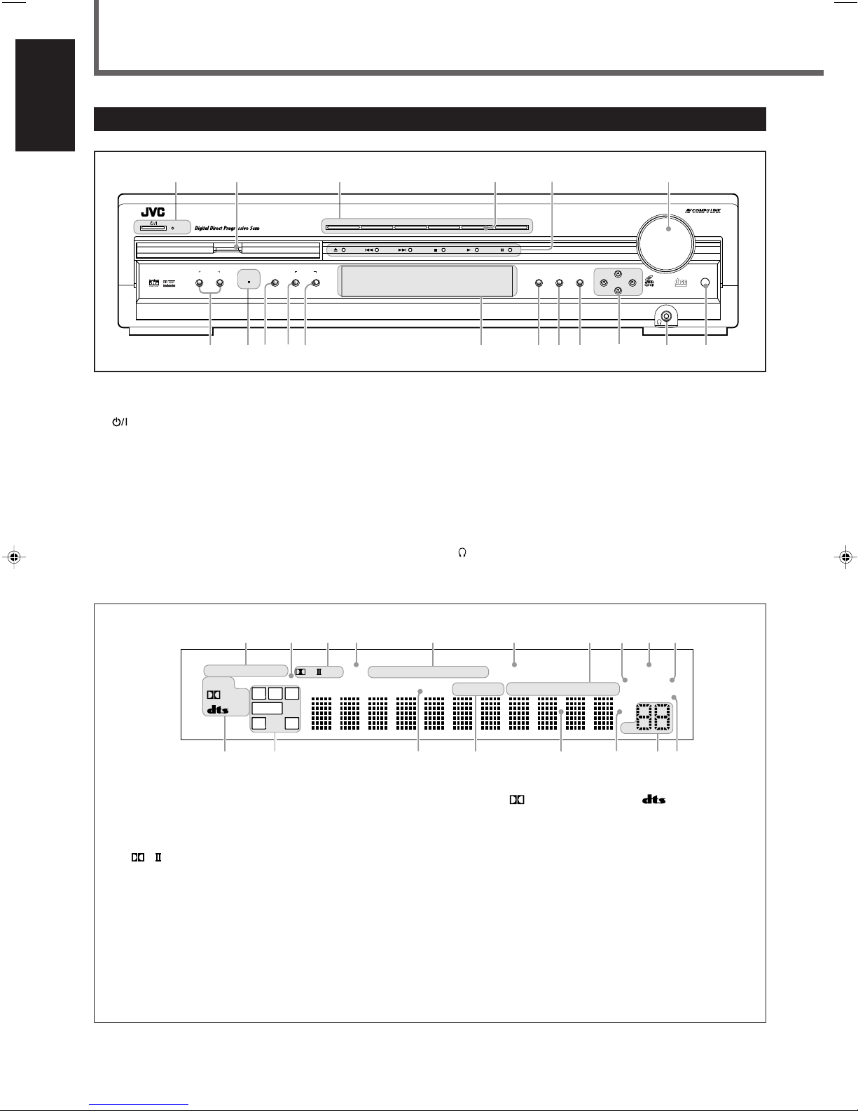
Front Panel
See pages in the parentheses for details.
1 STANDBY/ON button and STANDBY lamp (12, 20)
2 Disc tray and illumination lamp (17)
3 Source selecting buttons (12)
• DVD, DBS, VCR, TV, TAPE/CDR, FM/AM
4 SOURCE NAME button (13)
5 DVD player operation buttons (17 – 19)
0 (open/close), 4 (reverse skip), ¢ (forward skip),
7 (stop), 3 (play), 8 (pause)
6 MASTER VOLUME control (12, 17)
7 SPEAKERS 1 button (13)
SPEAKERS 2 button (13)
8 DVD AUDIO lamp (17)
9 INPUT ANALOG/DIGITAL button (14, 15)
INPUT ATT. (attenuator) button (15)
p SURROUND ON/OFF button (32)
q SURROUND MODE button (32)
REC (recording) MODE button (16)
w Display
• For details, see “Display” below.
e SETTING button (23, 24)
r ADJUST button (28)
t MEMORY button (21, 23)
y CONTROL 5/∞/2/3 buttons (15, 20 – 25, 28)
(phones) jack (13)
u
i Remote sensor (11)
Display
1 Input mode indicators (15)
• ANALOG, DIGITAL AUTO
2 Surround indicators (27, 32)
• AUTO SURROUND, SURROUND
3 Surround mode indicators (30, 31)
, DSP
•
4 SLEEP indicator (14)
5 Play mode indicators (46 – 48)
• PROGRAM, REPEAT 1/A-B, RANDOM
6 PROGRESSIVE indicator (16)
7 Tuner mode indicators (20, 22)
• TUNED, STEREO, AUTO MUTING
8 Front speaker indicators (13)
SPK 1/2
9 INPUT ATT (attenuator) indicator (15)
0 REC (recording) indicator (16)
3
- Sound signal indicators (15)
• PPCM,
(Dolby Digital), (DTS Digital
Surround), LPCM
= Signal and speaker indicators (32)
• L, C , R, SUBWFR (Subwoofer), LFE (Low Frequency
Effect), LS, S, RS
~ RESUME indicator (18)
! DVD AUDIO indicators (17)
• B.S.P. (Browsable Still Picture), BONUS
@ Main display
# Frequency unit indicators
• kHz (for AM station), MHz (for FM station)
$ Volume indication
% A.POSITION (audio position) indicator (29)
Page 9
1
2
3
5
6
4
7
8
9
p
q
w
HOME CINEMA
DVD-AUDIO/VIDEO CONTROL CENTER
1
2
3
4
5
6
7
8
9
+10
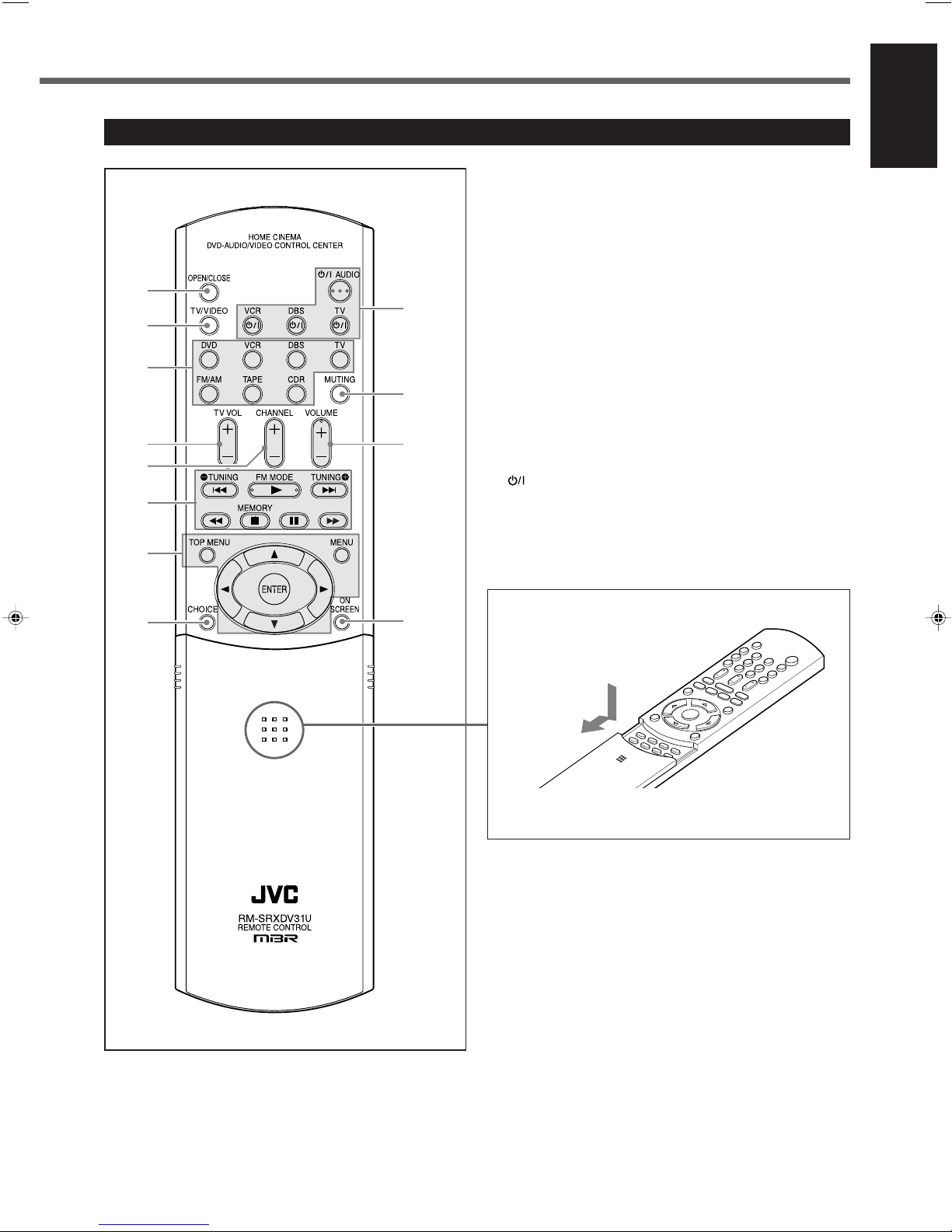
Remote Control
See pages in the parentheses for details.
1 OPEN/CLOSE button (17)
2 TV/VIDEO button (17, 66, 67)
3 Source selecting buttons (12)
• DVD, VCR, DBS, TV, FM/AM, TAPE, CDR
4 TV VOL (volume) +/– button (66, 67)
5 CHANNEL +/– button (66 – 68)
6 Multi operation buttons
• 4, 3, ¢, 1, 7, 8, ¡
• TUNING 9 and ( buttons (20)
• FM MODE button (22)
• MEMORY button (21)
7 Menu operation buttons
• TOP MENU button (38)
• MENU button (38)
• ENTER button
• Cursor 5/∞/3/2 buttons
8 CHOICE button (53, 54)
(standby/on) buttons (12, 66 – 69)
9
• AUDIO, VCR, DBS, TV
p MUTING button (14)
q VOLUME +/– button (12, 17)
w ON SCREEN button (36, 37, 39 – 43, 45 – 48)
English
To open the cover of the remote control, push here,
then slide downward.
• For buttons inside the cover, see “Remote control—
inside the cover” on page 5.
4
Page 10

Parts Identification
1
2
3
4
5
6
8
9
0
-
=
~
!
$
@
#
%
7
AM LOOP
FM 75
COAXIAL
AM EXT
DIGITAL 1
(DBS)
DIGITAL 2
(TV)
PCM/STREAM
SUBWOOFER
OUT
DIGITAL IN
ANTENNA
TV TAPE / CDR DBS VCR
AUDIO
Y
DBS
IN
DBS
IN
MONITOR
OUT
MONITOR
OUT
CAUTION:
SPEAKER
IMPEDANCE
1 OR 2:
16 32
816
CAUTION:
SPEAKER
IMPEDANCE
816
AV COMPU LINK-
RIGHT
LEFT
IN INOUT
(REC)IN(PLAY)
OUT
(REC)IN(PLAY)
DIGITAL OUT
VCR
OUT
(REC)IN(PLAY)
VCR
OUT
(REC)IN(PLAY)
SURROUND
SPEAKERS
RIGHT LEFTRIGHT LEFTRIGHT LEFT
CENTER
SPEAKER
FRONT SPEAKERS
1 AND 2:
1 2
PBP
R
VIDEO OUT SELECT
PAL NTSC
VOLTAGE
SELECTOR
110V
127V
230-240V
220V
4
5
6
32
1
879
qw
e
p
English
Remote control—inside the cover
1 SUBTITLE button (39)
2 AUDIO button (40)
3 ZOOM button (44)
4 ANGLE button (39)
5 REPEAT button (48, 50, 52)
6 PAGE button (43)
7 PROGRESSIVE button (16)
8 VFP button (45)
9 Sound adjustment buttons (29, 33, 65)
• BASS + and – buttons
• TREBLE + and – buttons
• TEST button
• EFFECT button
• SUBWFR (subwoofer) + and – buttons
• CENTER + and – buttons
• SURR L (surround left) + and – buttons
• SURR R (surround right) + and – buttons
0 TITLE/GROUP button (41, 50, 51)
- RETURN button (38)
= Number buttons
• For selecting preset channels (21, 22)
• For operating audio/video components (66 – 69)
• TV RETURN button (66, 67)
~ SLEEP button (14)
! DIMMER button (14)
@ ANALOG/DIGITAL INPUT button (14, 15)
# DECODE button (15)
$ AUDIO POSITION button (29)
% Surround buttons (32)
• SURROUND MODE button
• SURROUND ON/OFF button
Rear Panel
See pages in the parentheses for details.
1 VOLTAGE SELECTOR (1)
2 Speaker terminals (7)
• FRONT SPEAKERS 1, FRONT SPEAKERS 2, CENTER
SPEAKER, SURROUND SPEAKERS
3 SUB-WOOFER OUT jack (7)
4 S-VIDEO input/output terminals (9, 10)
• Input: DBS IN, VCR IN
• Output: VCR OUT, MONITOR OUT
5 DIGITAL IN terminals (11)
• Coaxial: DIGITAL 1 (DBS)
• Optical: DIGITAL 2 (TV)
5
6 DIGITAL OUT terminal (11)
7 Power cord
8 AV COMPU LINK-
terminals (63)
9 AUDIO input/output terminals (9, 10)
• Input: TV IN, TAPE/CDR IN, DBS IN, VCR IN
• Output: TAPE/CDR OUT, VCR OUT
p VIDEO OUT SELECT switch (8)
q DVD COMPONENT VIDEO OUT terminals (9)
• Y/P
w FM/AM ANTENNA terminals (6)
e VIDEO input/output terminals (9, 10)
• Input: DBS IN, VCR IN
• Output: VCR OUT, MONITOR OUT
B/PR
Page 11
CAUTION:
SPEAKER
IMPEDANCE
1 OR 2:
16 32
816
CAUTION:
SPEAKER
IMPEDANCE
816
1 AND 2:
VOLTAGE
SELECTOR
110V
127V
230-240V
220V
ANTENNA
AM LOOP
FM 75
COAXIAL
AM EXT
FM 75
COAXIAL
1
23
1
2
Getting Started
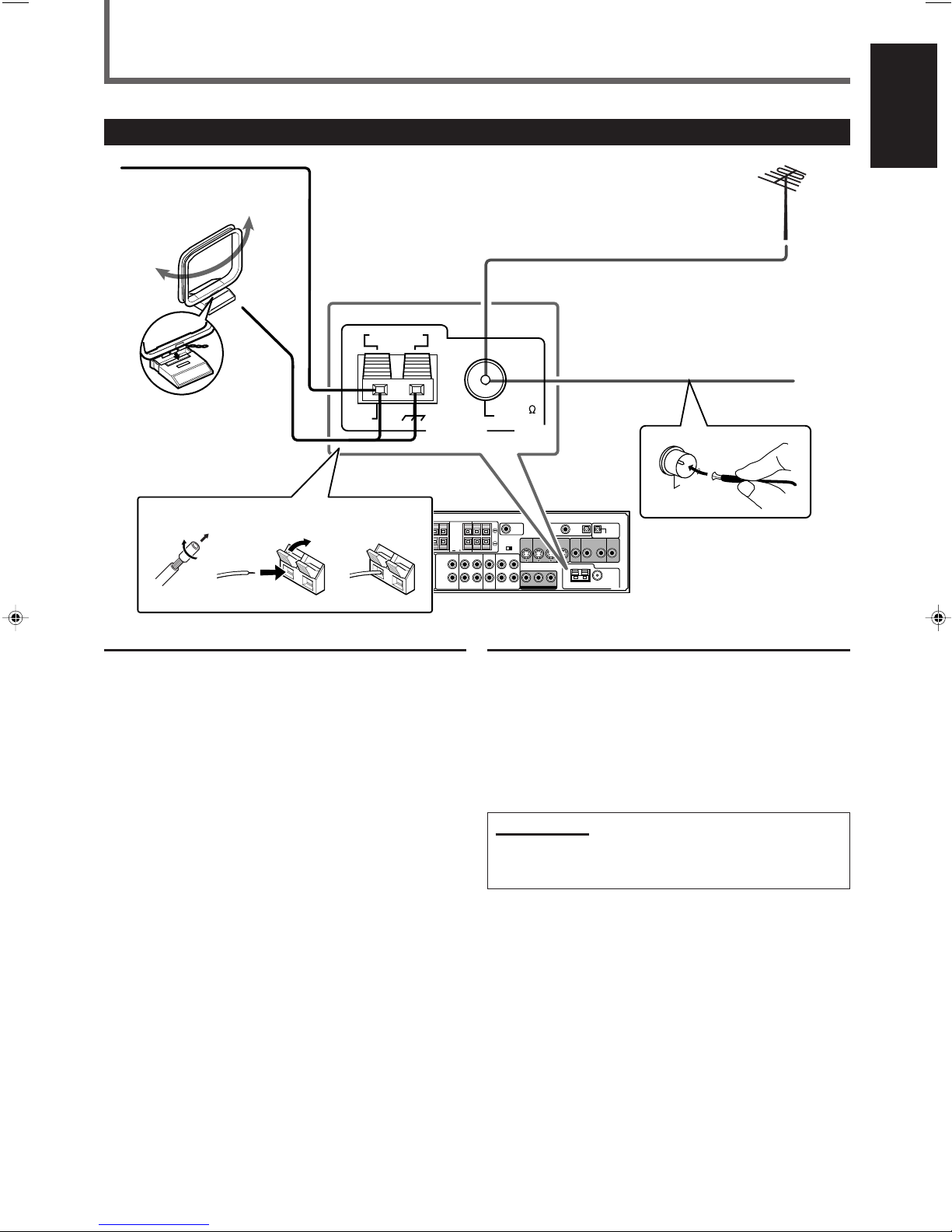
Connecting the AM and FM Antennas
If AM reception is poor,
AM loop antenna
(supplied)
Snap the tabs on the loop
into the slots of the base
to assemble the AM loop
antenna.
connect an outdoor
single vinyl-covered wire
(not supplied).
English
If FM reception is poor, connect
outdoor FM antenna (not supplied).
FM antenna (supplied)
AM antenna connection
Connect the AM loop antenna supplied to the AM LOOP
terminals.
1
Remove the insulation if the AM loop antenna wire is
covered with vinyl.
2
Press and hold the clamp of the terminal (1), then insert
the wire (2).
3
Release the clamp.
Turn the loop until you have the best reception.
• If the reception is poor, connect an outdoor single vinylcovered wire (not supplied) to the AM EXT terminal. Keep
the AM loop antenna connected.
FM antenna connection
Connect the FM antenna supplied to the FM 75 Ω COAXIAL
terminal as temporary measure.
Extend the supplied FM antenna horizontally.
• If the reception is poor, connect an outdoor FM antenna
(not supplied). Before attaching a 75 Ω coaxial cable with a
connector (IEC or DIN45325), disconnect the supplied FM
antenna.
Note:
• Make sure the antenna conductors do not touch any other
terminals, connecting cords and power cord. This could cause
poor reception.
6
Page 12
Getting Started
CAUTION:
SPEAKER
IMPEDANCE
1 OR 2:
16 32
816
CAUTION:
SPEAKER
IMPEDANCE
816
1 AND 2:
VOLTAGE
SELECTOR
110V
127V
230-240V
220V
SUBWOOFER
OUT
CAUTION:
SPEAKER
IMPEDANCE
1 OR 2:
16 32
816
CAUTION:
SPEAKER
IMPEDANCE
816
SURROUND
SPEAKERS
RIGHT LEFTRIGHT LEFTRIGHT LEFT
CENTER
SPEAKER
FRONT SPEAKERS
1 AND 2:
1 2
English
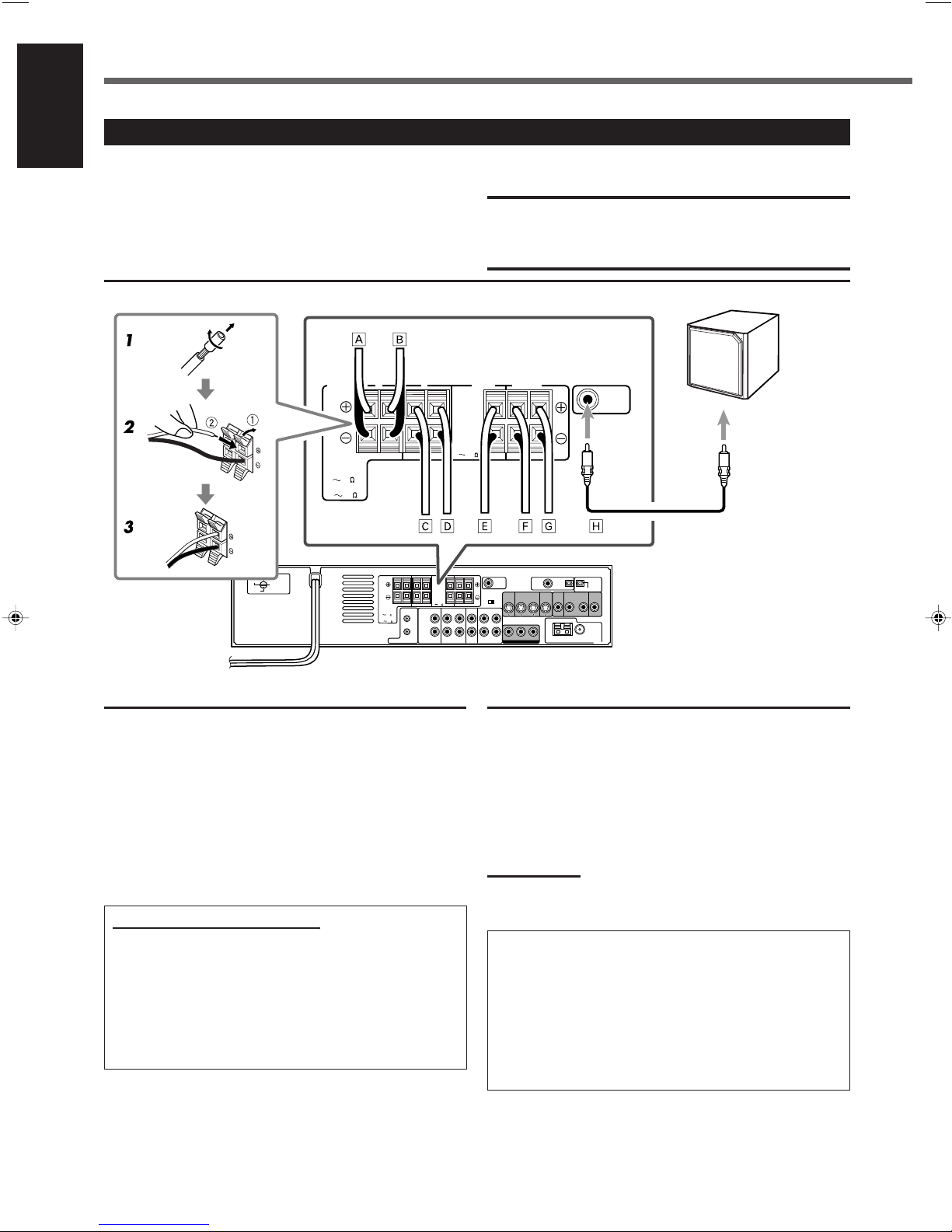
Connecting the Speakers
You can connect following speakers to this unit:
• two pairs of front speakers
– FRONT SPEAKERS 1 terminals
– FRONT SPEAKERS 2 terminals
• a pair of surround speakers
• a center speaker
• a subwoofer
Connection diagram
CAUTIONS:
• Use speakers with the SPEAKER IMPEDANCE indicated by
the speaker terminals.
• DO NOT connect more than one speaker to one speaker
terminal.
Powered subwoofer
(example)
Å To right front speaker 1
ı To left front speaker 1
Ç To right front speaker 2
Î To left front speaker 2
‰ To center speaker
Ï To right surround speaker
Ì To left surround speaker
Ó To input jack of a subwoofer
How to connect speakers cords
For each speaker, connect the (+) and (–) terminals on the
rear panel to the (+) and (–) terminals marked on the
speakers respectively.
1
Twist and remove the insulation at the end of each
speaker cord (not supplied).
2
Press and hold the clamp of the speaker terminal (1),
then insert the speaker cord (2).
3
Release the clamp.
About the speaker impedance
The required speaker impedance of the front speakers
differs depending on whether both the FRONT SPEAKERS
1 and FRONT SPEAKERS 2 terminals are used or only one
of them is used.
• When you connect only one pair of front speakers, use
front speakers with 8 Ω – 16 Ω impedance.
• When you connect both pairs of front speakers, use front
speakers with 16 Ω – 32 Ω impedance.
7
Connecting the subwoofer speaker
By connecting a subwoofer, you can enhance the bass or
reproduce the original LFE signals recorded in the digital
software.
Connect the input jack of a powered subwoofer to the SUBWOOFER OUT jack on the rear panel, using a cable with
RCA pin plugs (not supplied).
• Refer also to the manual supplied with your subwoofer.
Note:
• You can place a subwoofer wherever you like since bass sound is
non-directional. Normally place it in front of you.
To obtain the best possible sound from this system, place
all the speakers except the subwoofer at the same
distance from the listening position with each speaker’s
front faced toward the listener.
Then, change the subwoofer and speaker settings to fit
your listening conditions (see pages 24 to 26).
• You can set the speakers quickly according to the
number of speakers you have connected.
See “Setting Speakers Quickly” on page 23.
Page 13
A
B
C
A
B
C
Connecting Audio/Video Components
VIDEO OUT SELECT
PAL NTSC
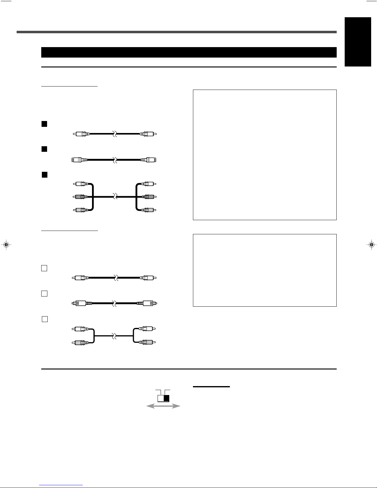
7 About connecting cords
For video connections
The S-video cords and the component video cord are not
supplied with this unit.
Use the cords supplied with the other components or
purchase them at your dealer.
Composite video cord (supplied)
S-video cord (not supplied)
Component video cord (not supplied)
Green
Blue
Red
For audio connections
Connect the external components to this unit with the audio
cords.
Use the cord supplied with the other components or
purchase them at your dealer.
Digital coaxial cord (not supplied)
Optical digital cord (not supplied)
English
Notes for video connection
• You can use composite video cord or S-video cord for
connecting the DBS tuner and VCR to this unit.
• You can use component video cord in addition to composite
video cord and S-video cord for connecting your TV to this unit.
• By using S-video cord or component video, you can get a better
picture quality—in the order: composite < S-video < component.
• To view the picture from DBS tuner or VCR on your TV, connect
your TV to this unit using the same type of cord for connecting
the DBS tuner or VCR to this unit.
• To view the picture from the built-in DVD player, connect the TV
to this unit using composite video cord, S-video cord, or
component video cord, then register the video output mode
correctly (see “Video output mode” on page 27).
• To enjoy the progressive video picture, connect the TV
compatible with the progressive video input using component
video cord, then change the scanning mode correctly (see
“Changing the Scanning Mode” on page 16).
You can enjoy the progressive scanning mode only when
the color system of your TV is NTSC (see “Setting the color
system” below).
Notes for digital connection
• When the unit is shipped from the factory, the DIGITAL IN
terminals are set for use with the following components:
– DIGITAL 1 (coaxial): For DBS tuner
– DIGITAL 2 (optical): For TV
• If you connect the CD recorder, change the digital input
(DIGITAL IN) terminal setting (see “Digital input (DIGITAL IN)
terminals” on page 27) and the source name (see “Changing the
Source Name” on page 13) correctly.
• Select the digital input mode correctly (see “Selecting the
Analog or Digital Input Mode” on page 14).
Audio cord (not supplied)
White
Red
7 Setting the color system
This unit is compatible with both the PAL
system and the NTSC system. To match
the color system of your TV, you can
change the color system of this unit by
switching the VIDEO OUT SELECT on the
rear.
Set the color system of this unit while the unit is turned
off.
• Before you play back a disc, make sure that the color
system of the disc matches your TV.
Notes:
• When the unit is shipped from the factory, the VIDEO OUT SELECT
switch is set to NTSC.
• If you change the VIDEO OUT SELECT setting while the unit is
turned on, the setting will not take effect until you turn on the unit
again.
• When you use a multi color system TV, you can change the color
system of this unit automatically by selecting “MULTI” options as the
monitor type in the PICTURE menu (see page 55). In this case, the
setting of this unit is changed to match the color system of the
loaded disc regardless the VIDEO OUT SELECT setting.
8
Page 14
CAUTION:
SPEAKER
IMPEDANCE
1 OR 2:
16 32
816
CAUTION:
SPEAKER
IMPEDANCE
816
1 AND 2:
TV TAPE / CDR DBS VCR
AUDIO
RIGHT
LEFT
IN INOUT
(REC)IN(PLAY)
OUT
(REC)IN(PLAY)
DBS
IN
DBS
IN
MONITOR
OUT
MONITOR
OUT
VCR
OUT
(REC)IN(PLAY)
VCR
OUT
(REC)IN(PLAY)
LEFT
RIGHT
AUDIO
OUT
B
A
C
CAUTION:
SPEAKER
IMPEDANCE
1 OR 2:
16 32
816
CAUTION:
SPEAKER
IMPEDANCE
816
1 AND 2:
VOLTAGE
SELECTOR
0V
27V
DBS
IN
DBS
IN
MONITOR
OUT
MONITOR
OUT
VCR
OUT
(REC)IN(PLAY)
VCR
OUT
(REC)IN(PLAY)
TV TAPE / CDR DBS VCR
AUDIO
RIGHT
LEFT
IN INOUT
(REC)IN(PLAY)
OUT
(REC)IN(PLAY)
LEFT
RIGHT
AUDIO
OUT
B
A
C
C
Getting Started
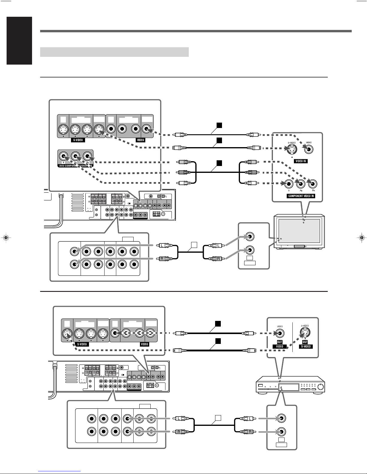
Turn off all the components and the unit before connection.
English
• Illustrations of the input/output terminals below are typical examples. When you connect other components, refer also to their
manuals since the terminal names actually printed on their rear vary among the components.
7 TV connection
DO NOT use a TV through a VCR or a TV with a built-in VCR; Otherwise, the picture may be distorted.
Connect using one of the video terminals.
7 DBS tuner connection
Connect using one of the video terminals.
White
Red
Red
Blue
Green
Red
Blue
Green
White
Red
• You can change the color system of this unit (see page 8).
TV
9
DBS tuner
White
Red
White
Red
Page 15
CAUTION:
SPEAKER
IMPEDANCE
1 OR 2:
16 32
816
CAUTION:
SPEAKER
IMPEDANCE
816
1 AND 2:
TV TAPE / CDR DBS VCR
AUDIO
RIGHT
LEFT
IN INOUT
(REC)IN(PLAY)
OUT
(REC)IN(PLAY)
LEFT
RIGHT
AUDIO
INOUT
C
C
CAUTION:
SPEAKER
IMPEDANCE
1 OR 2:
16 32
816
CAUTION:
SPEAKER
IMPEDANCE
816
1 AND 2:
VOLTAGE
SELECTOR
DBS
IN
DBS
IN
MONITOR
OUT
MONITOR
OUT
VCR
OUT
(REC)IN(PLAY)
VCR
OUT
(REC)IN(PLAY)
TV TAPE / CDR DBS VCR
AUDIO
RIGHT
LEFT
IN INOUT
(REC)IN(PLAY)
OUT
(REC)IN(PLAY)
LEFT
RIGHT
AUDIO
OUT IN
B
B
A
C
C
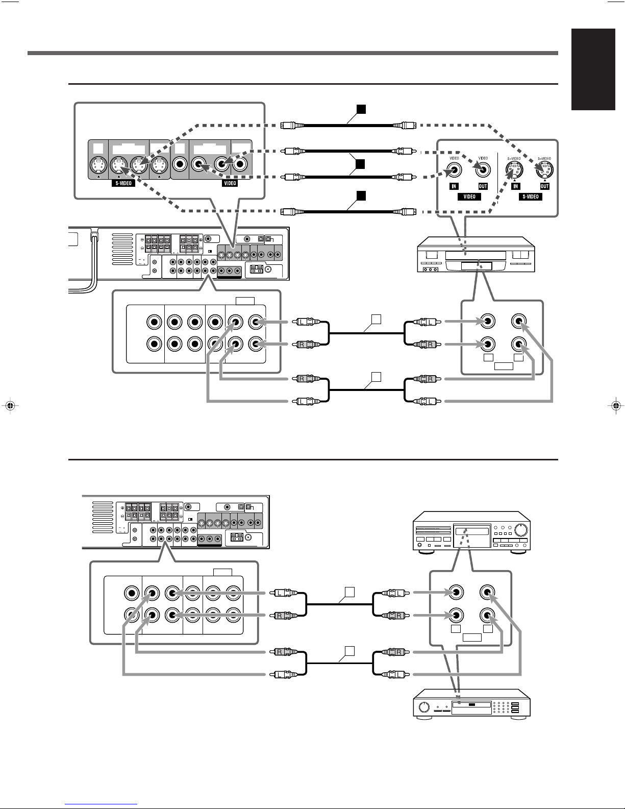
7 VCR connection
Connect using one of the video terminals.
English
VCR
7 Cassette deck/CD recorder connection
White
Red
Red
White
White
Red
Red
White
Cassette deck
White
White
Red
Red
White
Red
Red
White
CD recorder
10
Page 16
Getting Started
CAUTION:
SPEAKER
IMPEDANCE
816
DIGITAL 1
(DBS)
DIGITAL 2
(TV)
DIGITAL IN
DIGITAL
OUT
DIGITAL
IN
DIGITAL
OUT
PCM/STREAM
DIGITAL OUT
B
A
B
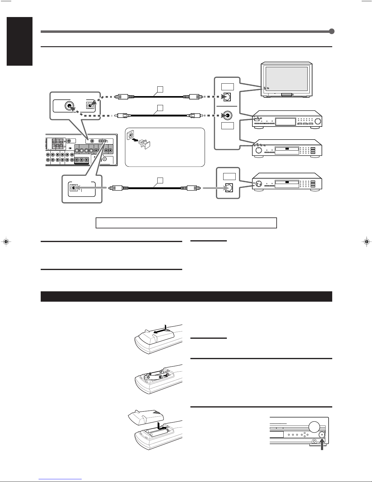
7 Digital connection
English
You can connect either of
the following components
to DIGITAL IN terminals.
TV
DBS tuner
Before connecting an
optical digital cord,
unplug the protective
plug.
Connect the CD recorder using the
DIGITAL OUT terminal for digital
recording.
Now, you can plug the power cord of the unit into the AC outlet.
CAUTIONS:
• Do not touch the power cord with wet hands.
• Do not pull on the power cord to unplug the cord. When
unplugging the cord, always grasp the plug so as not to
damage the cord.
Putting Batteries in the Remote Control
Before using the remote control, put two supplied batteries
first.
1
Press and slide the battery
cover on the back of the
remote control.
CD recorder
CD recorder
Notes:
• Keep the power cord away from the connecting cords and the
antenna cables. The power cord may cause noise or screen
interference.
• The preset settings such as preset channels and sound adjustment
may be erased in a few days in the following cases:
– When you unplug the power cord.
– When a power failure occurs.
If the range or effectiveness of the remote control decreases,
replace the batteries. Use two R6P(SUM-3)/AA(15F) type drycell batteries.
Note:
Supplied batteries are for the initial setup. Replace for continued use.
2
Insert batteries. Make sure
to match the polarity: (+) to
(+) and (–) to (–).
3
Replace the cover.
11
CAUTION:
Follow these precautions to avoid leaking or cracking cells:
• Place batteries in the remote control so they match the
polarity: (+) to (+) and (–) to (–).
• Use the correct type of batteries. Batteries that look similar
may differ in voltage.
• Always replace both batteries at the same time.
• Do not expose batteries to heat or flame.
When using the remote control,
aim the remote control directly at
the remote sensor on the unit.
Remote sensor
Page 17
Basic Operations
MASTER VOLUME
STANDBY
STANDBY/ON
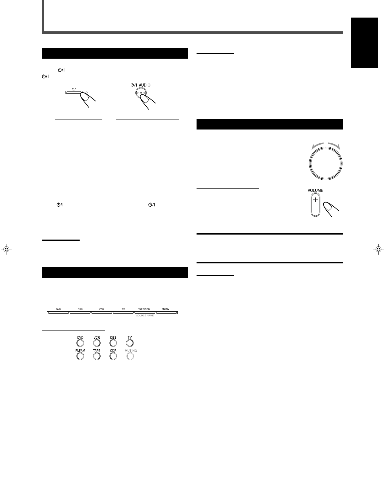
Turning On the Power
Press STANDBY/ON on the front panel or
AUDIO on the remote control.
On the front panel From the remote control
The STANDBY lamp goes off and the illumination lamp lights
up.
The current source name appears on the display.
• If “DVD” is the current source, “READING” appears while
the unit is detecting the type of the loaded disc (see page
34).
– Playback starts automatically when you load some DVD
VIDEO.
– “NO DISC” appears on the display when no disc is
loaded.
To turn off the power (into standby)
Press
the remote control again.
The illumination lamp goes off and the STANDBY lamp lights
up.
Note:
• A small amount of power is consumed even in standby mode. To
STANDBY/ON on the front panel or AUDIO on
turn off the power completely, unplug the AC power cord.
Notes:
• When you have connected some digital components using the
digital terminals (see page 11), register the digital input terminal
setting (see “Digital input (DIGITAL IN) terminals” on page 27) and
digital input mode setting correctly (see “Selecting the Analog or
Digital Input Mode” on page 14). Source name and “DIGITAL” will be
shown on the display when you select the source.
*
You can use only one of the buttons—TAPE or CDR—whichever
the source name is activated (see “Changing the Source Name” on
page 13).
Adjusting the Volume
On the front panel
To increase the volume,
turn MASTER VOLUME clockwise.
To decrease the volume,
turn MASTER VOLUME counterclockwise.
From the remote control
To increase the volume,
press and hold VOLUME +.
To decrease the volume,
press and hold VOLUME –.
CAUTION:
Always set the volume to the minimum before starting any
source. If the volume is set at a high level, the sudden blast of
sound energy can permanently damage your hearing and/or
ruin your speakers.
English
Selecting the Source to Play
Press one of the source selecting buttons.
On the front panel
From the remote control
DVD Select the built-in DVD player.
DBS Select the DBS tuner.
VCR Select the VCR.
TV Select the TV tuner.
TAPE/CDR Select the cassette deck or the CD recorder
(front panel ONLY).
TAPE* Select the cassette deck (remote control
ONLY).
CDR* Select the CD recorder (remote control ONLY).
FM/AM Select an FM or AM broadcast.
Notes:
• The volume level can be adjusted within the range of “0” (minimum)
to “50” (maximum).
• When “DVD” is selected as the source with your TV turned on, the
volume level indication appears on the TV.
12
Page 18
Basic Operations
MPEG-2AAC
TA NEWS INFO
ANALOGSDIGITAL AUTO DSP SLEEP REPEAT RANDOM RDS INPUT ATT
SPK 1 2
AUTO MODE
A.POSITION
PROGRESSIVE1A-B
DIGITAL
LPCM
LFE
PPCM AUTO
SURROUND
GROUP TITLE TRACK CHAP.
RESUME
kHz
MHz
VOL
BONUSB.S.P TUNED STEREO AUTO MUTING
PL
SUBWFR
L C R
LS RS
PROGRAM
REC
ASSGN. CDRASSGN. TAPE
7 Listening with headphones
English
Connect a pair of headphones to the (phones) jack on
the front panel
.
This cancels the Surround mode currently selected,
deactivates speakers, and activates the HEADPHONE mode.
The SPK 1 and 2 indicators go off from the display.
• Disconnecting a pair of headphones from the
jack cancels the HEADPHONE mode and activates
speakers.
HEADPHONE mode
When using the headphones, the following signals are
output regardless of your speaker setting:
– For 2-channel sources, the front left and right channel
signals are output directly from the left and right
headphones.
– For multi-channel sources, the front left and right,
center, and surround channel signals are down-mixed
and then output from the headphones without missing
bass element.
– For DVD AUDIO ONLY: When down-mixing is prohibited
on the disc, only signals of the front left and right channel
are output.
CAUTION:
Be sure to turn down the volume:
• Before connecting or putting on headphones, as high
volume can damage both the headphones and your
hearing.
• Before removing headphones, as high volume may come
out of the speakers.
Selecting the Front Speakers
When you have connected two pairs of front speakers, you
can select which to use.
(phones)
To use both pairs of the speakers
Press SPEAKERS 1 and 2 so that the SPK 1 and 2 indicators
light up on the display.
To use neither pairs of the speakers
Press SPEAKERS 1 and 2 so that the SPK 1 and SPK 2
indicators go off from the display.
• This activates the HEADPHONE mode (“HEADPHONE”
appears on the display).
Notes:
• If you select any of the Surround modes while using both pairs of
the front speakers connected to the FRONT SPEAKERS 1 and 2
terminals, the speakers connected to the FRONT SPEAKERS 2
terminals are deactivated.
• While the Surround mode is in use, you can only select either the
speakers connected to the FRONT SPEAKERS 1 or 2 terminals.
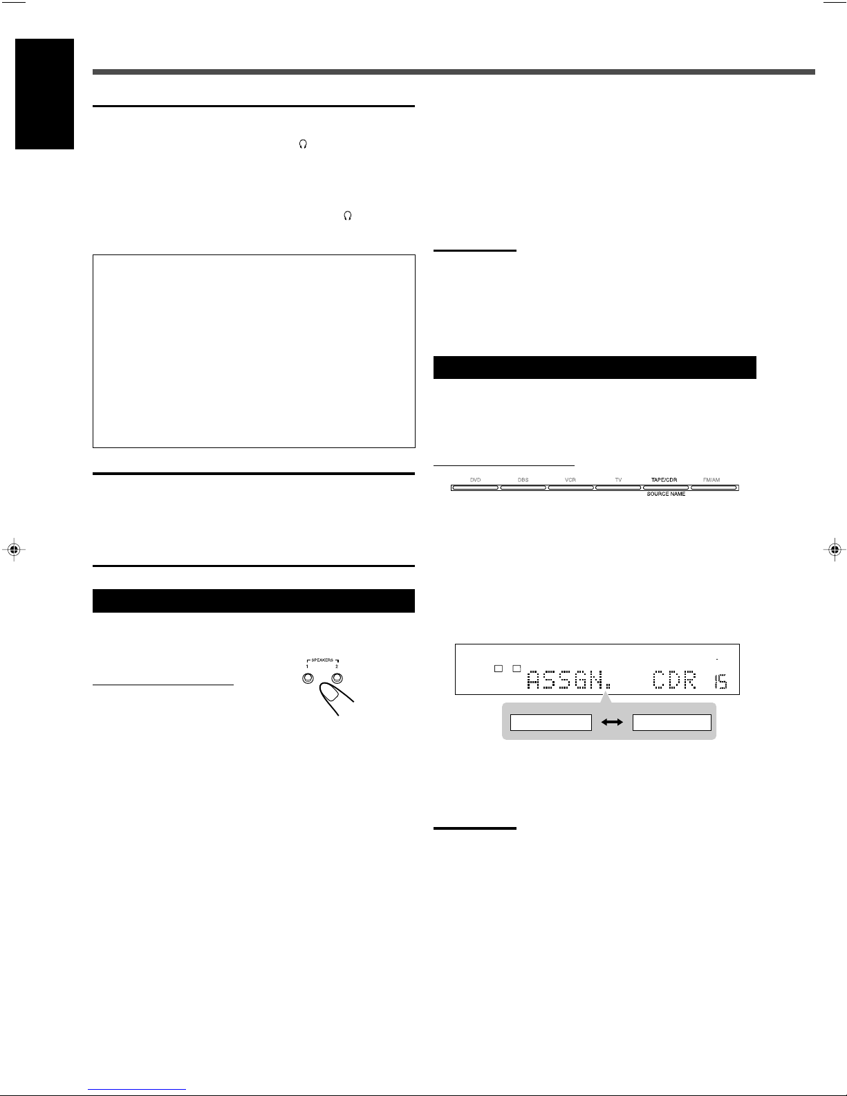
Changing the Source Name
When you connect a CD recorder to the TAPE/CDR jacks on
the rear panel, change the source name which will be shown
on the display.
On the front panel ONLY
Ex.: When changing the source name from “TAPE” to
“CDR”
1
Press TAPE/CDR (SOURCE NAME) to select
as the source.
2
Press and hold SOURCE NAME (TAPE/CDR)
until “ASSGN. CDR” appears on the display.
On the front panel ONLY
To use the speakers connected to the FRONT SPEAKERS
1 terminals
Press SPEAKERS 1 so that the SPK 1 indicator lights up on
the display. (Make sure that SPK 2 is not lit on the display.)
To use the speakers connected to the FRONT SPEAKERS
2 terminals
Press SPEAKERS 2 so that the SPK 2 indicator lights up on
the display. (Make sure that SPK 1 is not lit on the display.)
13
To change the source name to “TAPE”
Press and hold SOURCE NAME (TAPE/CDR) until
2
“ASSGN. TAPE” appears on the display in step
Note:
• Without changing the source name, you can still use the connected
components. However, there may be some inconveniences:
– The unexpected source name will appear on the display when you
press TAPE/CDR (SOURCE NAME) on the front panel.
– The CDR or TAPE button on the remote control will not work for
selecting the source.
– You cannot use the digital input (see page 27) for the CD
recorder.
.
Page 19
Turning Off the Sound Temporarily
MPEG-2AAC
TA NEWS INFO
ANALOGSDIGITAL AUTO DSP SLEEP REPEAT RANDOM RDS INPUT ATT
SPK 1 2
AUTO MODE
A.POSITION
PROGRESSIVE1A-B
DIGITAL
LPCM
LFE
PPCM AUTO
SURROUND
GROUP TITLE TRACK CHAP.
RESUME
kHz
MHz
VOL
BONUSB.S.P TUNED STEREO AUTO MUTING
PL
SUBWFR
L C R
LS RS
PROGRAM
REC
MPEG-2AAC
TA NEWS INFO
ANALOGSDIGITAL AUTO DSP SLEEP REPEAT RANDOM RDS INPUT ATT
SPK 1 2
AUTO MODE
A.POSITION
PROGRESSIVE1A-B
DIGITAL
LPCM
LFE
PPCM AUTO
SURROUND
GROUP TITLE TRACK CHAP.
RESUME
kHz
MHz
VOL
BONUSB.S.P TUNED STEREO AUTO MUTING
PL
SUBWFR
L C R
LS RS
PROGRAM
REC
(back to the beginning)
10 20 30 60
90 120 150 0 (off)
MPEG-2AAC
TA NEWS INFO
ANALOGSDIGITAL AUTO DSP SLEEP REPEAT RANDOM RDS INPUT ATT
SPK 1 2
AUTO MODE
A.POSITION
PROGRESSIVE1A-B
DIGITAL
LPCM
LFE
PPCM AUTO
SURROUND
GROUP TITLE TRACK CHAP.
RESUME
kHz
MHz
VOL
BONUSB.S.P TUNED STEREO AUTO MUTING
PL
SUBWFR
L C R
LS RS
PROGRAM
REC
DGTL AUTO ANALOG
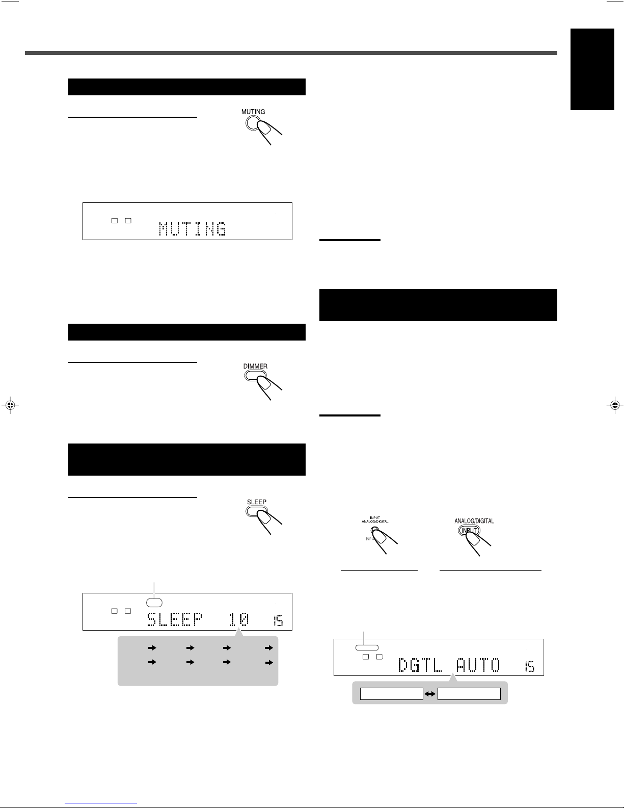
From the remote control ONLY
Press MUTING to mute the sound.
“MUTING” appears on the display and the volume turns off
(the volume indication goes off).
• When “DVD” is selected as the source with your TV turned
on, “VOLUME –” appears on the TV.
To restore the sound
Press MUTING again.
• Pressing VOLUME + or – on the remote control (or turn
MASTER VOLUME on the front panel) also restores the
sound.
To check or change the remaining time until the shut-off
time
Press SLEEP once.
• The remaining time (in minutes) until the shut-off time
appears.
To change the shut-off time
Press SLEEP repeatedly.
To cancel the Sleep Timer
Press SLEEP repeatedly until “SLEEP 0” appears on the
display. (The SLEEP indicator goes off.)
• Turning off the unit also cancels the Sleep Timer.
Note:
• If Auto Standby (see page 58) and Sleep Timer are used at the
same time, the one with the earlier shut-off time will turn off the
unit.
Selecting the Analog or Digital Input
Mode
English
Changing the Display Brightness
From the remote control ONLY
Press DIMMER to dim the display.
• Each time you press the button, the display and illumination
lamp dim and brighten alternately.
Turning Off the Power
with the Sleep Timer
From the remote control ONLY
Press SLEEP repeatedly.
The SLEEP indicator lights up on the display.
• Each time you press the button, the shut-off time changes
as follows:
SLEEP indicator
When you have connected digital source components using
both the analog connection and the digital connection
methods (see pages 9 to 11), you can select the input mode.
• Before selecting the digital input mode, register the digital
input terminal setting correctly (see “Digital input (DIGITAL
IN) terminals” on page 27).
Note:
• You cannot change the input mode when selecting “DVD” as the
source. Digital input is always used for the built-in DVD player.
1
Select a source (DBS, TV, or CDR) for which
you want to change the input mode.
2
Press INPUT ANALOG/DIGITAL (INPUT ATT.)
on the front panel or ANALOG/DIGITAL
INPUT on the remote control.
On the front panel From the remote control
The current input mode appears on the display.
• Each time you press the button, the input mode
alternates between the analog input (“ANALOG”) and
the digital input (“DGTL AUTO”).
DIGITAL AUTO indicator
When the shut-off time comes
The unit is turned off automatically.
TO BE CONTINUED TO THE NEXT PAGE
14
Page 20
DIGITAL
DIGITAL
Basic Operations
MPEG-2AAC
TA NEWS INFO
ANALOGSDIGITAL AUTO DSP SLEEP REPEAT RANDOM RDS INPUT ATT
SPK 1 2
AUTO MODE
A.POSITION
PROGRESSIVE1A-B
DIGITAL
LPCM
LFE
PPCM AUTO
SURROUND
GROUP TITLE TRACK CHAP.
RESUME
kHz
MHz
VOL
BONUSB.S.P TUNED STEREO AUTO MUTING
PL
SUBWFR
L C R
LS RS
PROGRAM
REC
DGTL D.D.
DGTL DTS
DGTL AUTO
MPEG-2AAC
TA NEWS INFO
ANALOGSDIGITAL AUTO DSP SLEEP REPEAT RANDOM RDS INPUT ATT
SPK 1 2
AUTO MODE
A.POSITION
PROGRESSIVE1A-B
DIGITAL
LPCM
LFE
PPCM AUTO
SURROUND
GROUP TITLE TRACK CHAP.
RESUME
kHz
MHz
VOL
BONUSB.S.P TUNED STEREO AUTO MUTING
PL
SUBWFR
L C R
LS RS
PROGRAM
REC
ATT NORMAL ATT ON
English
DGTL AUTO Select for the digital input mode.
The DIGITAL AUTO indicator lights up.
The unit automatically detects the
incoming signal format, then the sound
signal indicator for the detected signal
(see below) lights up; otherwise, no
sound signal indicators light up.
ANALOG Select for the analog input mode (initial
setting except for the built-in DVD
player).
The ANALOG indicator lights up.
Sound signal indicators on the display
PPCM Light when DVD AUDIO Packed PCM signals
come in.
• Light when Dolby Digital signals come in.
• Flash when “DGTL D.D.” is selected for
software not encoded with Dolby Digital
signals.
• Light when DTS signals come in.
• Flash when “DGTL DTS” is selected for
software not encoded with DTS signals.
LPCM Light when Linear PCM signals come in.
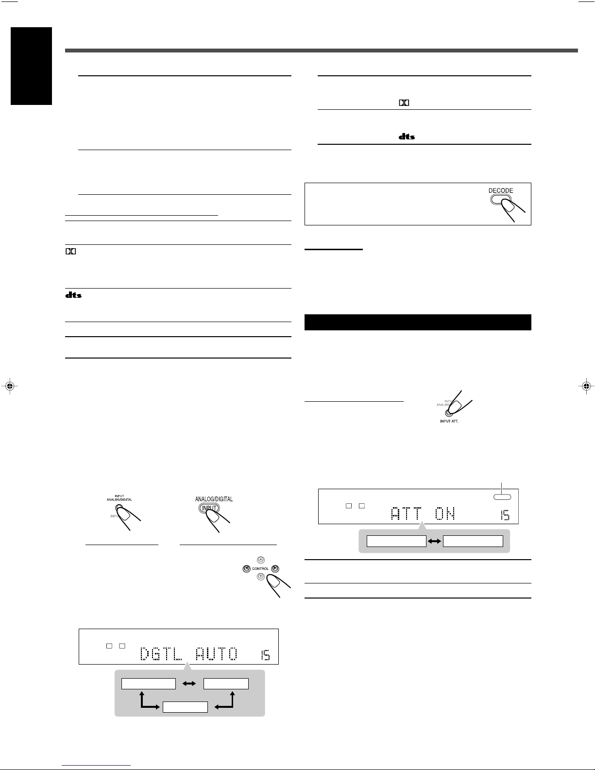
7 Changing the digital input mode
manually—for DVD VIDEO only
If the following symptoms occur while Dolby Digital or DTS
software is played back, try changing the digital input mode:
• Sound does not come out at the beginning of playback.
• Noise comes out while searching for or skipping chapters
or tracks.
1
Press INPUT ANALOG/DIGITAL (INPUT ATT.)
on the front panel or ANALOG/DIGITAL
INPUT on the remote control to select
“DGTL AUTO.”
DGTL D.D. Select for playing back software
encoded with Dolby Digital.
The
indicator lights up*.
DGTL DTS Select for playing back software
encoded with DTS.
The indicator lights up*.
* These indicators flash when no signal or a signal
without the proper format is played back.
You can also change the digital input mode by
pressing DECODE repeatedly on the remote
control.
Notes:
• When “DGTL AUTO” cannot recognize the incoming signals, no
sound signal indicators light up on the display.
• When you turn off the unit or select another source, “DGTL DTS”
and “DGTL D.D.” are canceled.
The digital input mode is automatically reset to “DGTL AUTO.”
Attenuating the Input Signal
When the input level of the analog source is too high, the
sounds will be distorted. If this happens, attenuate the input
signal level to prevent this sound distortion.
• You have to make this adjustment for each analog source.
On the front panel ONLY
Press and hold INPUT ATT. (INPUT ANALOG/DIGITAL)
until the INPUT ATT indicator lights up on the display.
• Each time you press and hold the button, the Input
Attenuator turns on (“ATT ON”) or off (“ATT NORMAL”).
INPUT ATT indicator
On the front panel From the remote control
2
Press CONTROL 3 (or 2) to
select “DGTL D.D.” or “DGTL
DTS” while “DGTL AUTO” still
remains on the display.
• Each time you press the button, the digital input mode
changes as follows:
15
ATT NORMAL Normally select this (initial setting).
The analog sound is not attenuated.
ATT ON Select when the analog sound is distorted.
Page 21

Changing the Scanning Mode
MPEG-2AAC
TA NEWS INFO
ANALOGSDIGITAL AUTO DSP SLEEP REPEAT RANDOM RDS INPUT ATT
SPK 1 2
AUTO MODE
A.POSITION
PROGRESSIVE1A-B
DIGITAL
LPCM
LFE
PPCM AUTO
SURROUND
GROUP TITLE TRACK CHAP.
RESUME
kHz
MHz
VOL
BONUSB.S.P TUNED STEREO AUTO MUTING
PL
SUBWFR
LCR
LS RS
PROGRAM
REC
Activating the Recording Mode
English
This unit supports the progressive scanning system (480p*)
as well as the conventional interlaced scanning system
(480i*).
If your TV has component video jacks and supports
progressive video input, you can enjoy a high quality picture
from the built-in DVD player.
• Refer also to the instruction manuals supplied with your TV.
• You cannot change the scanning mode when “PAL” is
selected as the color system of this unit. See page 8.
• You can select the picture source according to the original
picture type (film or video source). See “PICTURE
SOURCE” on page 55.
• Do not change the scanning mode to “PROGRESSIVE” in
the following cases:
– When your TV does not support the progressive video
input.
– When you are not connecting your TV to the unit using a
component video cord.
From the remote control ONLY
Press PROGRESSIVE when “DVD” is selected as the
source.
• Each time you press the button, the scanning mode
changes between “INTERLACE” and “PROGRESSIVE.”
INTERLACE Select for conventional TV (initial setting).
PROGRESSIVE Select if your TV with component jacks
supports the progressive video input. The
PROGRESSIVE indicator lights up.
Notes:
• Some progressive TVs and High-Definition TVs are not fully
compatible with this system. When an incompatible picture is played
back, change the scanning mode to “INTERLACE.” To check the
compatibility of your TV, contact your dealer.
All JVC progressive TVs and High-Definition TVs are fully
compatible with this system.
• When you select “PROGRESSIVE” as the scanning mode, the
picture does not come out correctly through composite video and
S-video jacks.
*
480p and 480i indicate the number of scanning lines and scanning
format of an image signal.
– 480p indicates 480 scanning lines with progressive format.
– 480i indicates 480 scanning lines with interlaced format.
When you play back the multi-channel sources, Recording
mode enables you to record the sounds without missing
surround elements by down-mixing the center and surround
channel signals into the front channel signals.
• When multi-channel software is played back with
Recording mode activated, the sounds are down-mixed
and come out through the front speakers only.
• For DVD AUDIO ONLY: When down-mixing is prohibited
on the disc, this function does not take effect.
On the front panel ONLY
Press and hold REC MODE (SURROUND MODE) until
“RECMODE ON” appears on the display.
The REC indicator lights up on the display.
REC indicator
• Each time you press and hold the button, Recording mode
is activated (“RECMODE ON”) and deactivated
(“RECMODE OFF”) alternately.
RECMODE OFF Normally select this (initial setting).
Down-mixing is canceled.
RECMODE ON Select for recording down-mixed sounds.
When recording onto the VCR:
You can record the picture on your video tape without the
volume level indication on the TV when Recording mode is
activated.
• When you do not want to record the on-screen guide icons,
see page 58.
• The choice menu (see page 53) and on-screen bar (see
page 36) are always recorded when they appear on the TV.
CAUTION:
Sound coming out of the speakers may be distorted by
Recording mode. In this case, decrease the volume until the
sound distortion diminishes.
Notes:
• When you turn off the unit or select another source, Recording
mode is canceled (“RECMODE OFF”).
• Sound adjustments (see pages 28 and 29) and Surround modes
(see pages 32 and 33) do not affect the recording.
• The following buttons do not work while Recording mode is
activated (“RECMODE ON”):
– SETTING and ADJUST on the front panel
– SURROUND ON/OFF and SURROUND MODE on the front panel
– Sound adjustment buttons on the remote control
16
Page 22
Basic DVD Player Operations
MASTER VOLUME
RX-DV31 HOME THEATER DVD-AUDIO/VIDEO RECEIVER
O
N
/O
F
F
SURROUND
M
O
D
E
MPEG-2AAC
TA NEWS INFO
ANALOGSDIGITAL AUTO DSP SLEEP REPEAT RANDOM RDS INPUT ATT
SPK 1 2
AUTO MODE
A.POSITION
PROGRESSIVE1A-B
DIGITAL
LPCM
LFE
PPCM AUTO
SURROUND
GROUP TITLE TRACK CHAP.
RESUME
kHz
MHz
VOL
BONUSB.S.P TUNED STEREO AUTO MUTING
PL
SUBWFR
LCR
LS RS
PROGRAM
REC
12
MPEG-2AAC
TA NEWS INFO
ANALOGSDIGITAL AUTO DSP SLEEP REPEAT RANDOM RDS INPUT ATT
SPK 1 2
AUTO MODE
A.POSITION
PROGRESSIVE1A-B
DIGITAL
LPCM
LFE
PPCM AUTO
SURROUND
GROUP TITLE TRACK CHAP.
RESUME
kHz
MHz
VOL
BONUSB.S.P TUNED STEREO AUTO MUTING
PL
SUBWFR
L C R
LS RS
PROGRAM
REC
1
2
MPEG-2AAC
TA NEWS INFO
ANALOGSDIGITAL AUTO DSP SLEEP REPEAT RANDOM RDS INPUT ATT
SPK 1 2
AUTO MODE
A.POSITION
PROGRESSIVE1A-B
DIGITAL
LPCM
LFE
PPCM AUTO
SURROUND
GROUP TITLE TRACK CHAP.
RESUME
kHz
MHz
VOL
BONUSB.S.P. TUNED STEREO AUTO MUTING
PL
SUBWFR
LCR
LS RS
PROGRAM
REC
12
34 5
For details about DVD player operations, see pages 34 to
English
48.
• You can also play back MP3 and JPEG files. See pages 49
to 52.
• To change the color system of this unit, see page 8.
• Before using the remote control, press DVD so that the
remote control works for the DVD player.
Before turning on the unit, turn on your TV and select the
correct video input (refer to the manual supplied with your
TV).
• When you use a JVC’s TV, you can turn on your TV by
pressing TV on the remote control and select the video
input by pressing TV/VIDEO. (If your TV is not a JVC, see
“Operating Other Manufacturers’ Equipment” on page 67.)
• For changing the OSD messages—the information on the
TV—into the desired language, see pages 53 to 55.
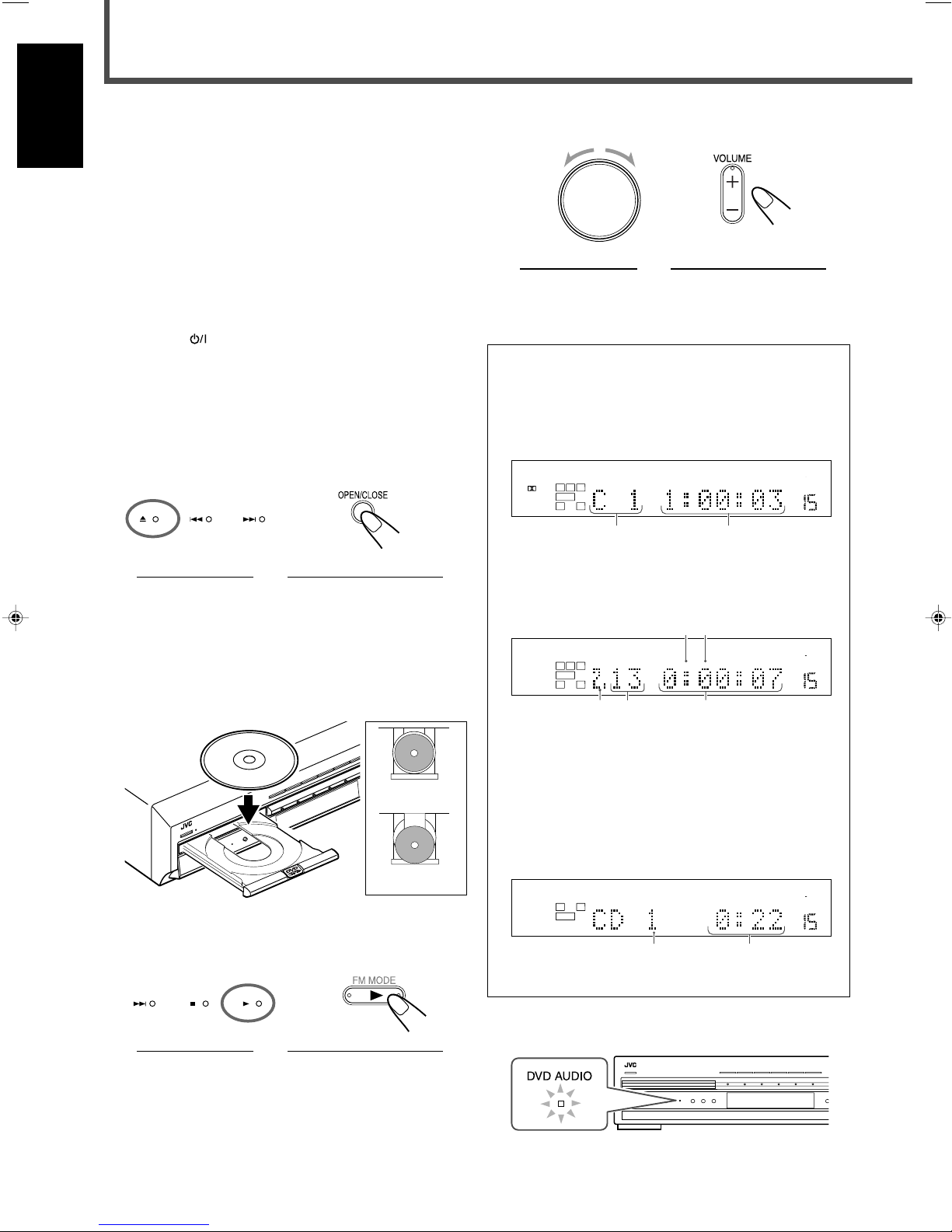
1
Press 0 on the front panel or OPEN/CLOSE
on the remote control to open the disc tray.
On the front panel From the remote control
The unit is turned on and the disc tray opens.
The STANDBY lamp goes off and the illumination lamp
lights up.
• When a disc is already loaded, pressing 3 turns on the
unit and starts playing back the loaded disc.
4
Adjust the volume.
On the front panel From the remote control
To activate and select Surround mode, see page 32.
About the indication on the display while playing back
a disc
While you are playing back a disc, the playback
information appears on the display as follows:
Ex.: When playing back a DVD VIDEO
1 Chapter number
2 Elapsed playing time
Ex.: When playing back a DVD AUDIO*
2
Load a disc.
Place a disc correctly with its label side up.
CORRECT
INCORRECT
3
Press 3.
The disc tray closes and the unit starts playing back the
loaded disc.
On the front panel From the remote control
• You can also close the disc tray by pressing 0 on the
front panel or OPEN/CLOSE on the remote control.
1 B.S.P (Browsable Still Picture) indicator (lights up when
you play back still pictures)
2 BONUS indicator (lights up when the disc has a bonus
group.)
3 Group number
4 Track number
5 Elapsed playing time
Ex.: When playing back an audio CD
1 Track number
2 Elapsed playing time
* When a DVD AUDIO is loaded, the DVD AUDIO lamp
lights up on the front panel.
17
Page 23
To stop playback
Press 7.
The unit memorizes the point where you stop playback and
the RESUME indicator lights up on the display (except when
an audio CD is loaded).
While the RESUME indicator is lit on the display, you can start
playback from the memorized point by pressing 3—Resume
play (see “About Resume play” on page 19).
To remove the loaded disc
Press 0 on the front panel or OPEN/CLOSE on the remote
control.
The disc tray opens.
After removing the disc, press the button again to close the
disc tray
• If you press
AUDIO on the remote control while the disc tray is open,
the disc tray closes automatically, then the unit is turned
off.
STANDBY/ON on the front panel or
To advance or reverse playback rapidly
• Press ¡ or 1 during playback (remote control ONLY).
Each time you press ¡ (or 1), the unit advances (or
reverses) playback, rapidly changing the playback speed
as follows:
For DVD VIDEO:
x2 ] x5 ] x10 ] x20 ] x60
For DVD AUDIO/VCD/SVCD/CD:
x2 ] x5 ] x10 ] x20
Pressing 3 resumes the normal playback.
• Press and hold ¢ or 4.
While you are pressing and holding ¢ (or 4), the unit
advances (or reverses) playback 5 times as fast as the
normal speed. When you press and hold ¢ (or 4)
further, the playback speed changes up to 20 times as fast
as the normal speed.
Releasing the button resumes the normal playback.
English
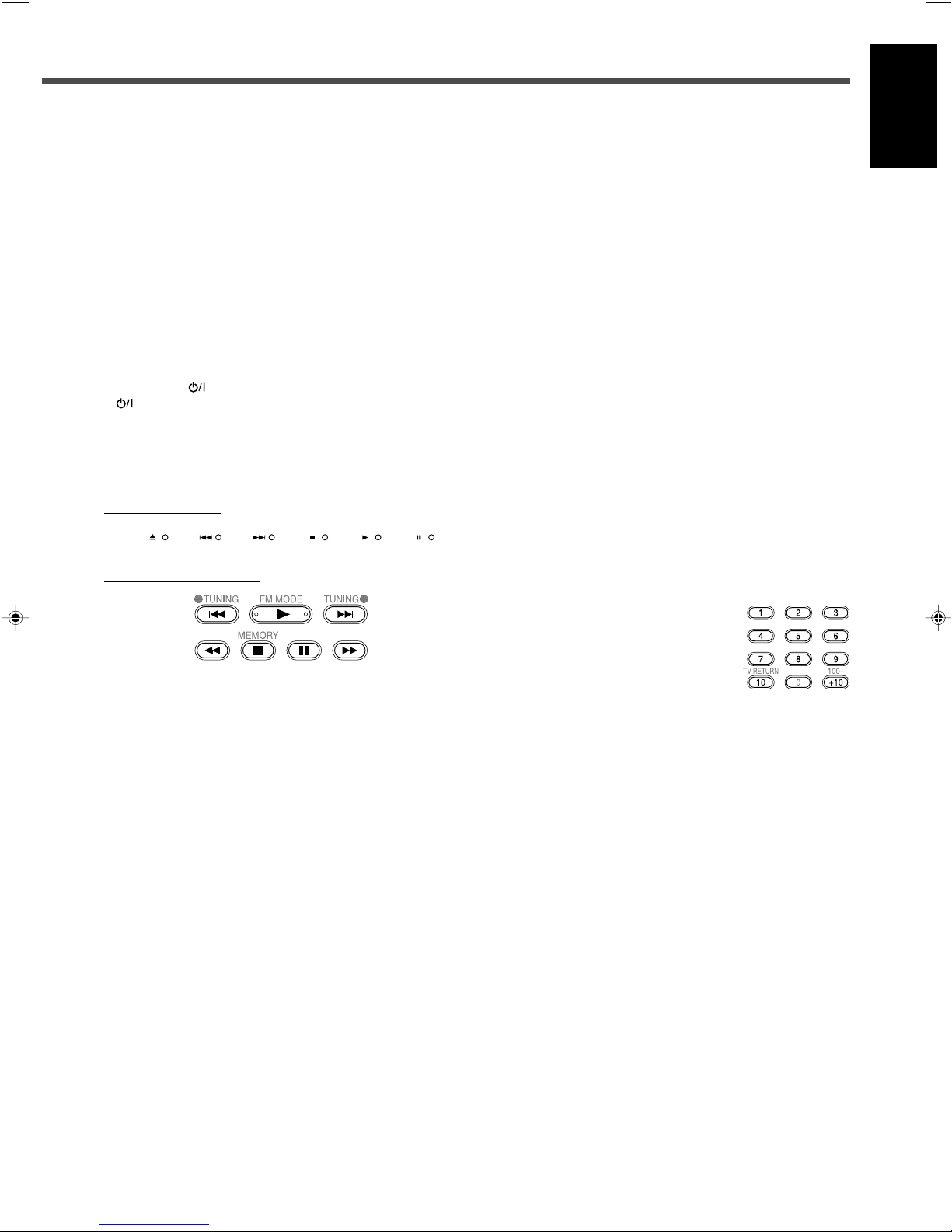
7 Other operation buttons for the DVD player
On the front panel
From the remote control
To stop playback temporarily
Press 8.
• Pressing 3 starts playback again.
To move back the playback position by 10 seconds
(for DVD VIDEO only)
Press 3 during DVD VIDEO playback.
The unit moves the playback position about 10 seconds
before the current position, then resumes playback.
To locate the beginning of the chapter or track
Press ¢ or 4.
Press ¢ (or 4) to locate the beginning of the next (current
or previous) chapter or track.
To locate the chapter or track using the number buttons
Press the number buttons (1 – 10, +10) to select the number
of the desired chapter or track.
Ex.: To select 3, press 3.
To select 11, press +10, then 1.
To select 20, press +10, then 10.
18
Page 24
Basic DVD Player Operations
About Resume play
English
This unit can memorize the point when you operate the
following procedures:
• Pressing 7 during play—Pressing 3 starts Resume play
• Changing the source—Pressing DVD or 3 starts
Resume play
• Turning off the unit (including Sleep Timer)—
Pressing 3 starts Resume play
Once you start Resume play, the RESUME indicator goes
off (the unit clears the memorized point).
The unit also clears the memorized point when you
operate the following procedures:
• Pressing 7 (while the RESUME indicator is lit on the
display)
• Selecting a track by pressing ¢ or 4 for video CD
and super VCD when playback stops
• Selecting program or random playback
• Pressing TOP MENU
• Ejecting the loaded disc
• Turning on the unit by pressing
front panel or
• Activating/deactivating Tray Lock.
You can cancel Resume play (see “Other setting menu—
OTHERS” on page 58).
AUDIO on the remote control
STANDBY/ON on the
About Tray Lock
You can prevent the disc tray from opening unintentionally
by using Tray Lock.
On the front panel ONLY
To lock the disc tray, press 0 while pressing SETTING
when the unit is in standby mode.
The unit is turned on and “LOCKED” appears on the
display for a little while.
• If you try to open the disc tray, “LOCKED” appears to let
you know that the Tray Lock is in use.
To unlock the disc tray, repeat the above procedure.
The unit is turned on and “UNLOCKED” appears briefly on
the display.
The disc tray is unlocked.
19
Page 25

Tuner Operations
MPEG-2AAC
TA NEWS INFO
ANALOGSDIGITAL AUTO DSP SLEEP REPEAT RANDOM RDS INPUT ATT
SPK 1 2
AUTO MODE
A.POSITION
PROGRESSIVE1A-B
DIGITAL
LPCM
LFE
PPCM AUTO
SURROUND
GROUP TITLE TRACK CHAP.
RESUME
kHz
MHz
VOL
BONUSB.S.P TUNED STEREO AUTO MUTING
PL
SUBWFR
L C R
LS RS
PROGRAM
REC
MPEG-2AAC
TA NEWS INFO
ANALOGSDIGITAL AUTO DSP SLEEP REPEAT RANDOM RDS INPUT ATT
SPK 1 2
AUTO MODE
A.POSITION
PROGRESSIVE1A-B
DIGITAL
LPCM
LFE
PPCM AUTO
SURROUND
GROUP TITLE TRACK CHAP.
RESUME
kHz
MHz
VOL
BONUSB.S.P TUNED STEREO AUTO MUTING
PL
SUBWFR
L C R
LS RS
PROGRAM
REC
MPEG-2AAC
TA NEWS INFO
ANALOGSDIGITAL AUTO DSP SLEEP REPEAT RANDOM RDS INPUT ATT
SPK 1 2
AUTO MODE
A.POSITION
PROGRESSIVE1A-B
DIGITAL
LPCM
LFE
PPCM AUTO
SURROUND
GROUP TITLE TRACK CHAP.
RESUME
kHz
MHz
VOL
BONUSB.S.P TUNED STEREO AUTO MUTING
PL
SUBWFR
L C R
LS RS
PROGRAM
REC
STANDBY
STANDBY/ON
STANDBY
STANDBY/ON
Setting the AM Tuner Interval Spacing
Some countries space AM stations 9 kHz apart, and other
countries use 10 kHz spacing.
• 10 kHz interval spacing is the initial setting.
On the front panel ONLY
1
Turn off the unit.
• Be sure that the unit is plugged into a wall outlet.
2
Change the interval spacing.
To set the AM tuner to the 9 kHz spacing:
Hold down CONTROL 2 and press
“9k STEP” appears on the display for a while.
To set the AM tuner to the 10 kHz spacing:
Hold down CONTROL 3 and press STANDBY/ON.
“10k STEP” appears on the display for a while.
STANDBY/ON.
3
While “< TUNING >” remains on the display,
press repeatedly or hold CONTROL 3 (or 2)
until you find the frequency you want.
• Pressing (or holding) CONTROL 3 increases the
frequency.
• Pressing (or holding) CONTROL 2 decreases the
frequency.
From the remote control
1
Press FM/AM.
The last received station of the selected band is
tuned in.
2
Press repeatedly or hold TUNING 9 or ( until you
find the frequency you want.
• Pressing (or holding) TUNING 9 increases the
frequency.
• Pressing (or holding) TUNING ( decreases the
frequency.
English
The unit turns on with the interval spacing changed.
Tuning in to Stations Manually
On the front panel
1
Press FM/AM to select the band.
The last received station of the selected band is tuned in.
The CONTROL buttons now work for tuner operations.
• Each time you press the button, the band alternates
between FM and AM.
Ex.: When selecting the FM band
2
Press CONTROL ∞ (or 5) repeatedly until
“< TUNING >” appears on the display.
Notes:
• When you hold and release CONTROL 3 (or TUNING 9 on the
remote control) or CONTROL 2 (or TUNING ( on the remote
control), the frequency keeps changing until a specific station is
tuned in.
• When a station of sufficient signal strength is tuned in, the TUNED
indicator lights up on the display.
• When an FM stereo program is received, the STEREO indicator
also lights up.
20
Page 26

Tuner Operations
MPEG-2AAC
TA NEWS INFO
ANALOGSDIGITAL AUTO DSP SLEEP REPEAT RANDOM RDS INPUT ATT
SPK 1 2
AUTO MODE
A.POSITION
PROGRESSIVE1A-B
DIGITAL
LPCM
LFE
PPCM AUTO
SURROUND
GROUP TITLE TRACK CHAP.
RESUME
kHz
MHz
VOL
BONUSB.S.P TUNED STEREO AUTO MUTING
PL
SUBWFR
L C R
LS RS
PROGRAM
REC
MPEG-2AAC
TA NEWS INFO
ANALOGSDIGITAL AUTO DSP SLEEP REPEAT RANDOM RDS INPUT ATT
SPK 1 2
AUTO MODE
A.POSITION
PROGRESSIVE1A-B
DIGITAL
LPCM
LFE
PPCM AUTO
SURROUND
GROUP TITLE TRACK CHAP.
RESUME
kHz
MHz
VOL
BONUSB.S.P TUNED STEREO AUTO MUTING
PL
SUBWFR
L C R
LS RS
PROGRAM
REC
MPEG-2AAC
TA NEWS INFO
ANALOGSDIGITAL AUTO DSP SLEEP REPEAT RANDOM RDS INPUT ATT
SPK 1 2
AUTO MODE
A.POSITION
PROGRESSIVE1A-B
DIGITAL
LPCM
LFE
PPCM AUTO
SURROUND
GROUP TITLE TRACK CHAP.
RESUME
kHz
MHz
VOL
BONUSB.S.P TUNED STEREO AUTO MUTING
PL
SUBWFR
L C R
LS RS
PROGRAM
REC
English
Using Preset Tuning
Once a station is assigned to a channel number, the station
can be tuned in quickly. You can preset up to 30 FM and 15
AM stations.
7 Storing preset stations
Before you start, remember...
There is a time limit in doing the following steps.
If the setting is canceled before you finish, start from step
again.
4
Press MEMORY again while the selected
channel number is flashing on the display.
The station is assigned to the selected channel number.
• The selected channel number stops flashing and then
the frequency flashes for about 5 seconds.
5
Press CONTROL 3 (or 2) to select another
frequency you want to store while the
frequency is flashing on the display.
6
2
Repeat steps 2 to 5 until you store all the
stations you want.
On the front panel
1
Tune in to the station you want to store (see
“Tuning in to Stations Manually” on page 20).
• If you want to store the FM reception mode for this
station, select the FM reception mode you want. See
“Selecting the FM Reception Mode” on page 22.
Ex.: When selecting the FM band
2
Press MEMORY.
The channel number position flashes on the display for
about 5 seconds.
3
Press CONTROL 3 (or 2) to select a
channel number while the channel number
position is flashing.
To erase a stored preset station
Storing a new station on a used channel number erases the
previously stored one.
From the remote control
After tuning in to the station you want to store,
1
Press MEMORY.
The channel number position flashes on the display for
about 5 seconds.
2
Press the number buttons to select a preset channel
number while the channel number position is flashing.
• For channel number 5, press 5.
• For channel number 15, press +10 then 5.
• For channel number 30, press +10, +10, then 10.
3
Press MEMORY again.
4
Press TUNING 9 or ( to select another frequency you
want to store.
5
Repeat steps 1 to 4 until you store all the stations you
want.
21
Page 27

7 Tuning in to a preset station
MPEG-2AAC
TA NEWS INFO
ANALOGSDIGITAL AUTO DSP SLEEP REPEAT RANDOM RDS INPUT ATT
SPK 1 2
AUTO MODE
A.POSITION
PROGRESSIVE1A-B
DIGITAL
LPCM
LFE
PPCM AUTO
SURROUND
GROUP TITLE TRACK CHAP.
RESUME
kHz
MHz
VOL
BONUSB.S.P TUNED STEREO AUTO MUTING
PL
SUBWFR
L C R
LS RS
PROGRAM
REC
MPEG-2AAC
TA NEWS INFO
ANALOGSDIGITAL AUTO DSP SLEEP REPEAT RANDOM RDS INPUT ATT
SPK 1 2
AUTO MODE
A.POSITION
PROGRESSIVE1A-B
DIGITAL
LPCM
LFE
PPCM AUTO
SURROUND
GROUP TITLE TRACK CHAP.
RESUME
kHz
MHz
VOL
BONUSB.S.P TUNED STEREO AUTO MUTING
PL
SUBWFR
L C R
LS RS
PROGRAM
REC
MPEG-2AAC
TA NEWS INFO
ANALOGSDIGITAL AUTO DSP SLEEP REPEAT RANDOM RDS INPUT ATT
SPK 1 2
AUTO MODE
A.POSITION
PROGRESSIVE1A-B
DIGITAL
LPCM
LFE
PPCM AUTO
SURROUND
GROUP TITLE TRACK CHAP.
RESUME
kHz
MHz
VOL
BONUSB.S.P TUNED STEREO AUTO MUTING
PL
SUBWFR
L C R
LS RS
PROGRAM
REC
Selecting the FM Reception Mode
English
On the front panel
1
Press FM/AM to select the band.
The last received station of the selected band is tuned in.
The CONTROL buttons now work for tuner operations.
Ex.: When selecting the FM band
2
Press CONTROL ∞ (or 5) repeatedly until
“< PRESET >” appears on the display.
3
While “< PRESET >” remains on the display,
press CONTROL 3 (or 2) to select a preset
channel number you want.
• Pressing (or holding) CONTROL 3 increases the preset
channel numbers.
• Pressing (or holding) CONTROL 2 decreases the
preset channel numbers.
From the remote control
1
Press FM/AM.
The last received station of the selected band is
tuned in.
The number buttons now work for tuner operations.
2
Press the number buttons to select a preset channel
number.
• For channel number 5, press 5.
• For channel number 15, press +10 then 5.
• For channel number 30, press +10, +10, then 10.
When an FM stereo broadcast is hard to receive or noisy, you
can change the FM reception mode while receiving an FM
broadcast.
• You can store the FM reception mode for each preset
station.
Before you start, remember...
There is a time limit in doing the following steps.
If the setting is canceled before you finish, start from step
1
again.
On the front panel
1
While listening to an FM station, press
CONTROL ∞ (or 5) repeatedly until
“< FM MODE >” appears on the display.
2
While “< FM MODE >” remains on the
display, press CONTROL 3 (or 2) to select
“MONO.”
• Each time you press the button, FM reception mode
alternates between “AUTO MUTING” and “MONO.”
AUTO MUTING Normally select this (initial setting).
When a program is broadcasted in
stereo, you will hear stereo sound; when
in monaural, you will hear monaural
sounds. This mode is also useful to
suppress static noise between stations.
The AUTO MUTING indicator lights up
on the display.
MONO Select to improve the reception (but
stereo effect will be lost).
In this mode, you will hear noise while
tuning in to the stations. The AUTO
MUTING indicator goes off from the
display. (The STEREO indicator also
goes off.)
To restore the stereo effect
Repeat step 1, then select “AUTO MUTING” in step 2.
From the remote control
1
Press FM/AM to select an FM station.
2
Press FM MODE.
• Each time you press the button, FM reception mode
alternates between “AUTO MUTING” and “MONO.”
22
Page 28

Basic Settings
MPEG-2AAC
TA NEWS INFOANALOGSDIGITAL AUTO DSP SLEEP REPEAT RANDOM RDS INPUT ATT
SPK 1 2
AUTO MODE
A.POSITION
PROGRESSIVE1A-B
DIGITAL
LPCM
LFE
PPCM AUTO
SURROUND
GROUP TITLE TRACK CHAP.
RESUME
kHz
MHz
VOL
BONUSB.S.P TUNED STEREO AUTO MUTING
PL
SUBWFR
L C R
LS RS
PROGRAM
REC
USE NO
MPEG-2AAC
TA NEWS INFOANALOGSDIGITAL AUTO DSP SLEEP REPEAT RANDOM RDS INPUT ATT
SPK 1 2
AUTO MODE
A.POSITION
PROGRESSIVE1A-B
DIGITAL
LPCM
LFE
PPCM AUTO
SURROUND
GROUP TITLE TRACK CHAP.
RESUME
kHz
MHz
VOL
BONUSB.S.P TUNED STEREO AUTO MUTING
PL
SUBWFR
L C R
LS RS
PROGRAM
REC
SMALL
MEDIUM
LARGE
MPEG-2AAC
TA NEWS INFO
ANALOGSDIGITAL AUTO DSP SLEEP REPEAT RANDOM RDS INPUT ATT
SPK 1 2
AUTO MODE
A.POSITION
PROGRESSIVE1A-B
DIGITAL
LPCM
LFE
PPCM AUTO
SURROUND
GROUP TITLE TRACK CHAP.
RESUME
kHz
MHz
VOL
BONUSB.S.P TUNED STEREO AUTO MUTING
PL
SUBWFR
L C R
LS RS
PROGRAM
REC
MPEG-2AAC
TA NEWS INFO
ANALOGSDIGITAL AUTO DSP SLEEP REPEAT RANDOM RDS INPUT ATT
SPK 1 2
AUTO MODE
A.POSITION
PROGRESSIVE1A-B
DIGITAL
LPCM
LFE
PPCM AUTO
SURROUND
GROUP TITLE TRACK CHAP.
RESUME
kHz
MHz
VOL
BONUSB.S.P TUNED STEREO AUTO MUTING
PL
SUBWFR
L C R
LS RS
PROGRAM
REC
4 SPEAKERS
3 SPEAKERS5 SPEAKERS
Some of the following settings are required after connecting
English
and positioning your speakers while others will make
operations easier.
7 Quick speaker setup (see below)
7 Basic item setup (see pages 24 to 27)
• Speaker settings
– Speaker information for subwoofer, front, center, and
surround speakers*
– Speaker distance for front, center, and surround
speakers*
– Crossover frequency*
– Low frequency effect attenuator*
– Dynamic range compression*
• Digital input (DIGITAL IN) terminals
• Auto surround
• Video output mode
*
You can also set these items using the Choice menu (see pages 53
to 58).
Setting Speakers Quickly
4
Press CONTROL 3 (or 2) to select an
appropriate number of the connected
speakers.
• Each time you press the button, the indication changes
as follows:
5 SPEAKERS Select when the front, center, and
surround speakers are connected (initial
setting).
4 SPEAKERS Select when the front and surround
speakers are connected.
3 SPEAKERS Select when the front and center
speakers are connected.
You can register the speaker size and distance easily for the
connected speakers (Quick Setup).
• To set the speaker size and distance manually, see
“Speaker information” and “Speaker distance” on page 25.
On the front panel ONLY
Before you start, remember...
There is a time limit in doing the following steps.
If the setting is canceled before you finish, start from step
1
again.
1
Press SETTING.
The CONTROL buttons now work for basic settings. The
setting item selected previously appears on the display.
For the configuration of the basic setting items, see
“Configuration of the items on the display” on page 24.
2
Press CONTROL ∞ (or 5) repeatedly until
“QUICK SETUP” appears on the display.
5
Press MEMORY.
“ENTER USE OF SUBWOOFER” scrolls on the display,
then “SUBWFR USE” appears.
6
Press CONTROL 3 (or 2) to select whether
you have connected a subwoofer or not.
• Each time you press the button, the indication changes
as follows:
USE Select when a subwoofer is connected (initial
setting).
NO Select when no subwoofer is used.
7
Press MEMORY.
“ENTER ROOM SIZE” scrolls on the display, then “SMALL
ROOM” appears.
8
Press CONTROL 3 (or 2) to select an
appropriate room size to match your
listening room.
• Each time you press the button, the indication changes
as follows:
3
Press MEMORY.
“ENTER THE NUMBER OF SPEAKERS” scrolls on the
display, then “5 SPEAKERS” appears.
23
Select an appropriate room size according to the distance
from your listening point to the speakers. See “Speaker
distance for each room size” on page 24.
Page 29

9
SUBWFR
(Subwoofer)
QUICK SETUP
*
2
(Quick setup)
FRNT SP
(Front speaker)
CNTR SP
(Center speaker)
SURR SP
(Surround speaker)
FRNT D
(Front distance)
CNTR D
(Center distance)
SURR D
(Surround distance)
CROSS
(Crossover)
LFE
(Low frequency
effect)
D.COMP
(Dynamic range
compression)
DGT
(Digital)
AUTO SR
(Auto surround)
VOUT
(Video out)
(back to the beginning)
2.4 m
2.1 m
1.5 m
L
R
C
LS
RS
2.7 m
2.4 m
2.1 m
L
R
C
LS
RS
L
R
C
LS
RS
3.0 m
Press MEMORY to finish the setting.
“SETUP END” appears on the display for a while, then
goes back to the source indication.
• Speaker configuration settings now become active.
For the registered speaker size and distance, see
below.
Note:
• This procedure will not be completed if you stop in the middle of the
process.
Speaker size for each speaker channel number
Selected value Speaker size
Number of Subwoofer Front L/R Center Surround L/R
speakers use (L/R) (C) (LS/RS)
3NOLRG SML NO
3 USE SML SML NO
4NOLRG NO SML
4 USE SML NO SML
5NOLRG SML SML
5 USE SML SML SML
• For details about speaker size, see page 25.
• When you select “LARGE” as the room size
Front 3.0 m
(L, R)
Center 3.0 m
Surround 3.0 m
(LS, RS)
Setting Basic Items
After completing connection, set the basic items listed on
page 23.
7 Operation buttons
On the front panel ONLY
English
Speaker distance for each room size
• When you select “SMALL” as the room size
• When you select “MEDIUM” as the room size
Front 2.4 m
(L, R)
Center 2.1 m
Surround 1.5 m
(LS, RS)
Front 2.7 m
(L, R)
Center 2.4 m
Surround 2.1 m
(LS, RS)
Button To do
SETTING Show the setting items on the display*1.
CONTROL 5/∞ Select an item on the display.
Each time you press the button, the items
change (see “Configuration of the items
on the display” below).
CONTROL 3/2 Adjust the selected item.
• When no operation is done for about 5 seconds, the
indications on the display will disappear.
1
Pressing SETTING repeatedly also changes the items.
*
Configuration of the items on the display
*2For details about “QUICK SETUP,” see “Setting Speakers
Quickly” on page 23.
24
Page 30

MPEG-2AAC
TA NEWS INFO
ANALOGSDIGITAL AUTO DSP SLEEP REPEAT RANDOM RDS INPUT ATT
SPK 1 2
AUTO MODE
A.POSITION
PROGRESSIVE1A-B
DIGITAL
LPCM
LFE
PPCM AUTO
SURROUND
GROUP TITLE TRACK CHAP.
RESUME
kHz
MHz
VOL
BONUSB.S.P TUNED STEREO AUTO MUTING
PL
SUBWFR
L C R
LS RS
PROGRAM
REC
MPEG-2AAC
TA NEWS INFO
ANALOGSDIGITAL AUTO DSP SLEEP REPEAT RANDOM RDS INPUT ATT
SPK 1 2
AUTO MODE
A.POSITION
PROGRESSIVE1A-B
DIGITAL
LPCM
LFE
PPCM AUTO
SURROUND
GROUP TITLE TRACK CHAP.
RESUME
kHz
MHz
VOL
BONUSB.S.P TUNED STEREO AUTO MUTING
PL
SUBWFR
L C R
LS RS
PROGRAM
REC
DGT1DBS 2TV DGT1DBS2CDR
DGT1TV 2DBS
DGT1CDR2DBS
DGT1CDR 2TV
DGT1TV 2CDR
(back to the beginning)
Basic Settings
MPEG-2AAC
TA NEWS INFO
ANALOGSDIGITAL AUTO DSP SLEEP REPEAT RANDOM RDS INPUT ATT
SPK 1 2
AUTO MODE
A.POSITION
PROGRESSIVE1A-B
DIGITAL
LPCM
LFE
PPCM AUTO
SURROUND
GROUP TITLE TRACK CHAP.
RESUME
kHz
MHz
VOL
BONUSB.S.P TUNED STEREO AUTO MUTING
PL
SUBWFR
L C R
LS RS
PROGRAM
REC
MPEG-2AAC
TA NEWS INFO
ANALOGSDIGITAL AUTO DSP SLEEP REPEAT RANDOM RDS INPUT ATT
SPK 1 2
AUTO MODE
A.POSITION
PROGRESSIVE1A-B
DIGITAL
LPCM
LFE
PPCM AUTO
SURROUND
GROUP TITLE TRACK CHAP.
RESUME
kHz
MHz
VOL
BONUSB.S.P TUNED STEREO AUTO MUTING
PL
SUBWFR
L C R
LS RS
PROGRAM
REC
MPEG-2AAC
TA NEWS INFO
ANALOGSDIGITAL AUTO DSP SLEEP REPEAT RANDOM RDS INPUT ATT
SPK 1 2
AUTO MODE
A.POSITION
PROGRESSIVE1A-B
DIGITAL
LPCM
LFE
PPCM AUTO
SURROUND
GROUP TITLE TRACK CHAP.
RESUME
kHz
MHz
VOL
BONUSB.S.P TUNED STEREO AUTO MUTING
PL
SUBWFR
L C R
LS RS
PROGRAM
REC
MPEG-2AAC
TA NEWS INFO
ANALOGSDIGITAL AUTO DSP SLEEP REPEAT RANDOM RDS INPUT ATT
SPK 1 2
AUTO MODE
A.POSITION
PROGRESSIVE1A-B
DIGITAL
LPCM
LFE
PPCM AUTO
SURROUND
GROUP TITLE TRACK CHAP.
RESUME
kHz
MHz
VOL
BONUSB.S.P TUNED STEREO AUTO MUTING
PL
SUBWFR
L C R
LS RS
PROGRAM
REC
MPEG-2AAC
TA NEWS INFO
ANALOGSDIGITAL AUTO DSP SLEEP REPEAT RANDOM RDS INPUT ATT
SPK 1 2
AUTO MODE
A.POSITION
PROGRESSIVE1A-B
DIGITAL
LPCM
LFE
PPCM AUTO
SURROUND
GROUP TITLE TRACK CHAP.
RESUME
kHz
MHz
VOL
BONUSB.S.P TUNED STEREO AUTO MUTING
PL
SUBWFR
L C R
LS RS
PROGRAM
REC
MPEG-2AAC
TA NEWS INFO
ANALOGSDIGITAL AUTO DSP SLEEP REPEAT RANDOM RDS INPUT ATT
SPK 1 2
AUTO MODE
A.POSITION
PROGRESSIVE1A-B
DIGITAL
LPCM
LFE
PPCM AUTO
SURROUND
GROUP TITLE TRACK CHAP.
RESUME
kHz
MHz
VOL
BONUSB.S.P TUNED STEREO AUTO MUTING
PL
SUBWFR
L C R
LS RS
PROGRAM
REC
MPEG-2AAC
TA NEWS INFO
ANALOGSDIGITAL AUTO DSP SLEEP REPEAT RANDOM RDS INPUT ATT
SPK 1 2
AUTO MODE
A.POSITION
PROGRESSIVE1A-B
DIGITAL
LPCM
LFE
PPCM AUTO
SURROUND
GROUP TITLE TRACK CHAP.
RESUME
kHz
MHz
VOL
BONUSB.S.P TUNED STEREO AUTO MUTING
PL
SUBWFR
L C R
LS RS
PROGRAM
REC
7 Operating procedure
English
Ex.: When setting the digital input (DIGITAL IN) terminals.
Before you start, remember...
There is a time limit in doing the following steps.
If the setting is canceled before you finish, start from step
again.
1
Press SETTING.
The CONTROL buttons now work for basic settings. The
setting item selected previously appears on the display.
2
Press CONTROL ∞ (or 5) repeatedly until
“DGT (Digital)” (with the current setting)
appears on the display.
3
Press CONTROL 3 (or 2) to select the
appropriate digital terminal setting.
• Each time you press the button, the indication changes
as follows:
¶ For front speakers—“FRNT SP”
1
¶ For center speaker—“CNTR SP”
¶ For surround speakers—“SURR SP”
Select one of the following settings for each speaker:
LRG (large) Select when the size of the cone
speaker unit built in your speaker is
greater than 12 cm.
SML (small) Select when the size of the cone
speaker unit built in your speaker is
smaller than 12 cm.
NO Select when you have not connected a
speaker (not selectable for the front
speakers).
4
Repeat steps 2 and 3 to set other items if
necessary.
• For details about each item, see below.
7 Speaker information
To obtain the best possible effect from the Surround modes
(see pages 32 and 33), register the following information after
all connections are completed.
• If you have used Quick Setup (see page 23), this setting is
not required.
¶ For subwoofer—“SUBWFR”
Select one of the following settings:
YES Select when a subwoofer is connected.
NO Select when no subwoofer is used (initial
setting).
Note:
• If you have selected “NO” for the subwoofer, you can only select
“LRG (large)” for the front speakers.
25
Notes:
•“LRG (large)” is the initial setting for the front speakers and
“SML (small)” for the center and surround speakers.
• If you have selected “SML (small)” for the front speakers, you
cannot select “LRG (large)” for the center and surround
speakers.
7 Speaker distance
¶ For front distance—“FRNT D”
¶ For center distance—“CNTR D”
¶ For surround distance—“SURR D”
Page 31

The distance from your listening point to the speakers is
MPEG-2AAC
TA NEWS INFO
ANALOGSDIGITAL AUTO DSP SLEEP REPEAT RANDOM RDS INPUT ATT
SPK 1 2
AUTO MODE
A.POSITION
PROGRESSIVE1A-B
DIGITAL
LPCM
LFE
PPCM AUTO
SURROUND
GROUP TITLE TRACK CHAP.
RESUME
kHz
MHz
VOL
BONUSB.S.P TUNED STEREO AUTO MUTING
PL
SUBWFR
LCR
LS RS
PROGRAM
REC
MPEG-2AAC
TA NEWS INFO
ANALOGSDIGITAL AUTO DSP SLEEP REPEAT RANDOM RDS INPUT ATT
SPK 1 2
AUTO MODE
A.POSITION
PROGRESSIVE1A-B
DIGITAL
LPCM
LFE
PPCM AUTO
SURROUND
GROUP TITLE TRACK CHAP.
RESUME
kHz
MHz
VOL
BONUSB.S.P TUNED STEREO AUTO MUTING
PL
SUBWFR
LCR
LS RS
PROGRAM
REC
MPEG-2AAC
TA NEWS INFO
ANALOGSDIGITAL AUTO DSP SLEEP REPEAT RANDOM RDS INPUT ATT
SPK 1 2
AUTO MODE
A.POSITION
PROGRESSIVE1A-B
DIGITAL
LPCM
LFE
PPCM AUTO
SURROUND
GROUP TITLE TRACK CHAP.
RESUME
kHz
MHz
VOL
BONUSB.S.P TUNED STEREO AUTO MUTING
PL
SUBWFR
L C R
LS RS
PROGRAM
REC
2.4 m
2.7 m
3.0 m
3.3 m
Left front
speaker
Right front
speaker
Right surround
speaker
Subwoofer
Left surround
speaker
Center speaker
another important element to obtain the best possible
surround sound from the Surround modes.
Set the distance from your listening point to the speakers. By
referring to the speaker distance setting, this unit
automatically sets the delay time of the sound through each
speaker so that sounds through all the speakers can reach
you at the same time.
• If you have used Quick Setup (see page 23), this setting is
not required.
Set the distance from the listening point within the range of
0.3 m to 9.0 m, in 0.3 m intervals.
Select one of the following settings:
80Hz Select when the cone speaker unit built in the
speaker is about 12 cm.
100Hz Select when the cone speaker unit built in the
speaker is about 10 cm (initial setting).
120Hz Select when the cone speaker unit built in the
speaker is about 8 cm.
Note:
• Crossover frequency is not valid for the HEADPHONE mode.
English
Notes:
•“3.0m” is the initial setting.
• If you have selected “NO” for the center and surround speakers
setting, you cannot set the speaker distance for the center and
surround speakers.
Ex.:In this case, set “FRNT D” to “3.3m,”
set “CNTR D” to “3.0m” and
set “SURR D” to “2.7m.”
7 Crossover frequency
“CROSS”
7 Low frequency effect attenuator
“LFE”
If the bass sound is distorted while playing back software
encoded with Dolby Digital or DTS, set the LFE level to
eliminate distortion.
• This function takes effect only when LFE signals come in.
Select one of the following settings:
0dB Normally select this (initial setting).
–10dB Select when the bass sound is distorted.
7 Dynamic range compression
“D.COMP”
You can compress the dynamic range (difference between
maximum sound and minimum sound) of the reproduced
sound. This is useful when enjoying surround sound at night.
• This function takes effect only when playing back a source
encoded with Dolby Digital.
Small speakers cannot reproduce the bass sounds efficiently.
If you use a small speaker in any position, this unit
automatically reallocates the bass sound elements assigned
to the small speaker to the large speakers.
To use this function properly, set the crossover frequency
level according to the size of the small speaker connected.
• If you have selected “LRG (large)” for all speakers, this
function will not take effect.
Select one of the following settings:
MID Select when you want to reduce the dynamic
range a little (initial setting).
MAX Select when you want to apply the compression
effect fully. (Useful at night.)
OFF Select when you want to enjoy surround with its full
dynamic range. (No effect applied.)
26
Page 32

Basic Settings
MPEG-2AAC
TA NEWS INFO
ANALOGSDIGITAL AUTO DSP SLEEP REPEAT RANDOM RDS INPUT ATT
SPK 1 2
AUTO MODE
A.POSITION
PROGRESSIVE1A-B
DIGITAL
LPCM
LFE
PPCM AUTO
SURROUND
GROUP TITLE TRACK CHAP.
RESUME
kHz
MHz
VOL
BONUSB.S.P TUNED STEREO AUTO MUTING
PL
SUBWFR
L C R
LS RS
PROGRAM
REC
MPEG-2AAC
TA NEWS INFO
ANALOGSDIGITAL AUTO DSP SLEEP REPEAT RANDOM RDS INPUT ATT
SPK 1 2
AUTO MODE
A.POSITION
PROGRESSIVE1A-B
DIGITAL
LPCM
LFE
PPCM AUTO
SURROUND
GROUP TITLE TRACK CHAP.
RESUME
kHz
MHz
VOL
BONUSB.S.P TUNED STEREO AUTO MUTING
PL
SUBWFR
L C R
LS RS
PROGRAM
REC
MPEG-2AAC
TA NEWS INFO
ANALOGSDIGITAL AUTO DSP SLEEP REPEAT RANDOM RDS INPUT ATT
SPK 1 2
AUTO MODE
A.POSITION
PROGRESSIVE1A-B
DIGITAL
LPCM
LFE
PPCM AUTO
SURROUND
GROUP TITLE TRACK CHAP.
RESUME
kHz
MHz
VOL
BONUSB.S.P TUNED STEREO AUTO MUTING
PL
SUBWFR
L C R
LS RS
PROGRAM
REC
7 Digital input (DIGITAL IN) terminals
English
“DGT”
When you use the digital input terminals, register what
components are connected to which terminals (DIGITAL IN 1/
DIGITAL IN 2), so that the correct source name will appear
when you select the digital source.
Set the appropriate digital terminal settings.
• Each time you press CONTROL 3 or 2, the settings
change as follows:
1 DBS 2 TV “ 1 DBS 2 CDR “ 1 TV 2 DBS “
1 TV 2 CDR “ 1 CDR 2 DBS “ 1 CDR 2 TV “
(back to the beginning)
Notes:
•“1DBS 2TV” is the initial setting.
• If you want to connect a CD recorder to the digital input terminal,
change the source name from “TAPE” to “CDR.”
For details, see “Changing the Source Name” on page 13.
Notes:
• This function does not take effect in the following cases:
– While playing an analog source.
– While selecting “DGTL D.D.” or “DGTL DTS” as the fixed digital
input mode (see page 15).
• If you press SURROUND ON/OFF with Auto Surround activated,
Auto Surround will be canceled temporarily for the currently
selected source.
Auto Surround setting will be restored in the following cases:
– When you turn off and on the unit,
– When you change the source,
– When you change the analog/digital input, and
– When you reset “AUTO SR” to “ON” again.
7 Video output mode
“VOUT”
After connecting your TV to the unit, register the type of the
connected video output terminal.
Without setting this, AV COMPU LINK does not work
appropriately when “DVD” is selected as the source (see
“AV COMPU LINK Remote Control System” on pages 63 and
64).
7 Auto surround
“AUTO SR”
Surround mode is automatically activated when a digital
multi-channel source such as Dolby Digital or DTS software
or 2-channel matrix source such as Dolby Surround is played
back.
You can enjoy Surround mode simply by selecting the source
(with digital input selected for that source)—Auto Surround.
Select one of the following settings:
ON The AUTO SURROUND indicator always lights up
on the display (initial setting).
• If multi-channel signals come in, an appropriate
Surround mode will be turned on.
• If Dolby Digital 2-channel or DTS 2-channel
including surround signals come in, “PLII
MOVIE” will be selected.
• If Dolby Digital 2-channel or DTS 2-channel
signals without surround signals come in,
“STEREO” will be selected.
• If the other signals come in, nothing will change.
OFF Select to deactivate Auto Surround.
Set the output terminal appropriately:
VIDEO Select when you connect your TV to the VIDEO
jack by using a composite video cord (initial
setting).
S Select when you connect your TV to the
S-VIDEO jack by using an S-video cord.
COMPNT Select when you connect your TV to the DVD
COMPONENT VIDEO OUT jacks by using a
component video cord.
27
Page 33

Sound Adjustments
BAL
(Balance)
SUBWFR
*
4
(Subwoofer)
BASS
TREBLE
CENTER
*
4
SURR R
*
4
(Surround right)
SURR L
*
4
(Surround left)
EFFECT
*
5
(back to the beginning)
AUDIO POS
*
6
(Audio position)
MPEG-2AAC
TA NEWS INFO
ANALOGSDIGITAL AUTO DSP SLEEP REPEAT RANDOM RDS INPUT ATT
SPK 1 2
AUTO MODE
A.POSITION
PROGRESSIVE1A-B
DIGITAL
LPCM
LFE
PPCM AUTO
SURROUND
GROUP TITLE TRACK CHAP.
RESUME
kHz
MHz
VOL
BONUSB.S.P TUNED STEREO AUTO MUTING
PL
SUBWFR
L C R
LS RS
PROGRAM
REC
MPEG-2AAC
TA NEWS INFO
ANALOGSDIGITAL AUTO DSP SLEEP REPEAT RANDOM RDS INPUT ATT
SPK 1 2
AUTO MODE
A.POSITION
PROGRESSIVE1A-B
DIGITAL
LPCM
LFE
PPCM AUTO
SURROUND
GROUP TITLE TRACK CHAP.
RESUME
kHz
MHz
VOL
BONUSB.S.P TUNED STEREO AUTO MUTING
PL
SUBWFR
L C R
LS RS
PROGRAM
REC
CENTERR –21 L –21
MPEG-2AAC
TA NEWS INFO
ANALOGSDIGITAL AUTO DSP SLEEP REPEAT RANDOM RDS INPUT ATT
SPK 1 2
AUTO MODE
A.POSITION
PROGRESSIVE1A-B
DIGITAL
LPCM
LFE
PPCM AUTO
SURROUND
GROUP TITLE TRACK CHAP.
RESUME
kHz
MHz
VOL
BONUSB.S.P TUNED STEREO AUTO MUTING
PL
SUBWFR
L C R
LS RS
PROGRAM
REC
You can make sound adjustments to your preference after
completing basic setting.
Adjustment items:
• Front speaker output balance*
1
• Tone*
• Speaker output levels*
1
1
• DAP effect level
• Subwoofer audio position
1
*
You can also make these adjustments using the Choice menu (see
pages 53 to 58).
Note:
• Adjustments you made are memorized separately for each source.
7 Operation buttons
On the front panel ONLY*
Button To do
ADJUST Show the adjustable items on the
display*
CONTROL 5/∞ Select an item on the display.
Each time you press the button, the
adjustable items change (see
“Configuration of the items on the
display” below).
CONTROL 3/2 Adjust the selected item.
• When no operation is done for about 5 seconds, the
indications on the display will disappear.
2
You can also make sound adjustment except for front
*
speakers’ output balance from the remote control.
*3Pressing ADJUST repeatedly also changes the items.
2
3
.
7 Operating procedure
Ex.: When setting the front speaker output balance.
Before you start, remember...
There is a time limit in doing the following steps.
If the setting is canceled before you finish, start from step
again.
1
Press ADJUST.
The CONTROL buttons now work for sound adjustments.
The setting item selected previously appears on the
display.
2
Press CONTROL ∞ (or 5) repeatedly until
“BAL (Balance)” (with the current setting)
appears on the display.
3
Press CONTROL 3 (or 2) to adjust the front
speaker balance.
• Each time you press the button, the indication changes
as follows:
4
Repeat steps 2 and 3 to set other items if
necessary.
• For details about each item, see below.
7 Front speaker output balance
“BAL (balance)”
English
1
Configuration of the items on the display
*4These items appear only when the corresponding
speakers are set to other than “NONE” as its speaker size.
5
“EFFECT” appears only when one of DAP modes (see
*
pages 30 and 31) is activated.
*6“AUDIO POS” appears only when “YES” or “USE” (see
pages 23, 25, or 57) is selected for the subwoofer.
If the sounds you hear from the front right and left speakers
are unequal, you can adjust the speaker output balance.
Adjust the output balance appropriately from the listening
point within the range of R (Right) –21 to CENTER (0) or
CENTER (0) to L (Left) –21 (“CENTER” is the initial setting).
Note:
• When you select “R –21,” no sound comes out of the front right
speaker, and when you select “L –21,” no sound comes out of the
front left speaker.
28
Page 34

MPEG-2AAC
TA NEWS INFO
ANALOGSDIGITAL AUTO DSP SLEEP REPEAT RANDOM RDS INPUT ATT
SPK 1 2
AUTO MODE
A.POSITION
PROGRESSIVE1A-B
DIGITAL
LPCM
LFE
PPCM AUTO
SURROUND
GROUP TITLE TRACK CHAP.
RESUME
kHz
MHz
VOL
BONUSB.S.P TUNED STEREO AUTO MUTING
PL
SUBWFR
LCR
LS RS
PROGRAM
REC
MPEG-2AAC
TA NEWS INFO
ANALOGSDIGITAL AUTO DSP SLEEP REPEAT RANDOM RDS INPUT ATT
SPK 1 2
AUTO MODE
A.POSITION
PROGRESSIVE1A-B
DIGITAL
LPCM
LFE
PPCM AUTO
SURROUND
GROUP TITLE TRACK CHAP.
RESUME
kHz
MHz
VOL
BONUSB.S.P TUNED STEREO AUTO MUTING
PL
SUBWFR
LCR
LS RS
PROGRAM
REC
MPEG-2AAC
TA NEWS INFO
ANALOGSDIGITAL AUTO DSP SLEEP REPEAT RANDOM RDS INPUT ATT
SPK 1 2
AUTO MODE
A.POSITION
PROGRESSIVE1A-B
DIGITAL
LPCM
LFE
PPCM AUTO
SURROUND
GROUP TITLE TRACK CHAP.
RESUME
kHz
MHz
VOL
BONUSB.S.P TUNED STEREO AUTO MUTING
PL
SUBWFR
L C R
LS RS
PROGRAM
REC
MPEG-2AAC
TA NEWS INFO
ANALOGSDIGITAL AUTO DSP SLEEP REPEAT RANDOM RDS INPUT ATT
SPK 1 2
AUTO MODE
A.POSITION
PROGRESSIVE1A-B
DIGITAL
LPCM
LFE
PPCM AUTO
SURROUND
GROUP TITLE TRACK CHAP.
RESUME
kHz
MHz
VOL
BONUSB.S.P TUNED STEREO AUTO MUTING
PL
SUBWFR
L C R
LS RS
PROGRAM
REC
MPEG-2AAC
TA NEWS INFO
ANALOGSDIGITAL AUTO DSP SLEEP REPEAT RANDOM RDS INPUT ATT
SPK 1 2
AUTO MODE
A.POSITION
PROGRESSIVE1A-B
DIGITAL
LPCM
LFE
PPCM AUTO
SURROUND
GROUP TITLE TRACK CHAP.
RESUME
kHz
MHz
VOL
BONUSB.S.P TUNED STEREO AUTO MUTING
PL
SUBWFR
L C R
LS RS
PROGRAM
REC
MPEG-2AAC
TA NEWS INFO
ANALOGSDIGITAL AUTO DSP SLEEP REPEAT RANDOM RDS INPUT ATT
SPK 1 2
AUTO MODE
A.POSITION
PROGRESSIVE1A-B
DIGITAL
LPCM
LFE
PPCM AUTO
SURROUND
GROUP TITLE TRACK CHAP.
RESUME
kHz
MHz
VOL
BONUSB.S.P TUNED STEREO AUTO MUTING
PL
SUBWFR
L C R
LS RS
PROGRAM
REC
MPEG-2AAC
TA NEWS INFO
ANALOGSDIGITAL AUTO DSP SLEEP REPEAT RANDOM RDS INPUT ATT
SPK 1 2
AUTO MODE
A.POSITION
PROGRESSIVE1A-B
DIGITAL
LPCM
LFE
PPCM AUTO
SURROUND
GROUP TITLE TRACK CHAP.
RESUME
kHz
MHz
VOL
BONUSB.S.P TUNED STEREO AUTO MUTING
PL
SUBWFR
L C R
LS RS
PROGRAM
REC
MPEG-2AAC
TA NEWS INFO
ANALOGSDIGITAL AUTO DSP SLEEP REPEAT RANDOM RDS INPUT ATT
SPK 1 2
AUTO MODE
A.POSITION
PROGRESSIVE1A-B
DIGITAL
LPCM
LFE
PPCM AUTO
SURROUND
GROUP TITLE TRACK CHAP.
RESUME
kHz
MHz
VOL
BONUSB.S.P TUNED STEREO AUTO MUTING
PL
SUBWFR
LCR
LS RS
PROGRAM
REC
Sound Adjustments
7 Tone
English
¶ For bass sound—“BASS”
¶ For treble sound—“TREBLE”
You can adjust the bass and treble sounds as you like.
Adjust the tone within a range of –10 dB to +10 dB in 2 step
intervals (“0” is the initial setting).
7 Speaker output levels
¶ For subwoofer—“SUBWFR”
¶ For center speaker—“CENTER”
¶ For left surround speaker—“SURR L”
¶ For right surround speaker—“SURR R”
7 Subwoofer audio position
“AUDIO POS (position)”
You may feel subwoofer is reinforced when listening stereo
sound.
In this case, you can automatically change the subwoofer
level properly when listening stereo sound.
• To adjust the subwoofer level, see the left column.
Select the automatic adjustment level from “0” to “–6” (in
2 step intervals).
If no adjustment is required, select “0” (initial setting). The
smaller the number becomes, the more the level decreases
automatically when listening in stereo.
• The A.POSITION indicator lights up when “AUDIO POS” is
set to other than “0.”
Note:
• You cannot adjust “AUDIO POS” when “NO” or “NONE” (see pages
25 or 57) is selected for the subwoofer.
Adjusting sound from the remote control
• To adjust bass sound,
press BASS + or –.
• To adjust treble sound,
press TREBLE + or –.
• To adjust subwoofer,
press SUBWFR + or –.
• To adjust center speaker,
press CENTER + or –.
• To adjust left surround
speaker, press SURR L + or –.
• To adjust right surround speaker, press SURR R + or –.
• To adjust the effect level (for DAP mode), press EFFECT.
• To adjust subwoofer audio position, press AUDIO
POSITION.
You can adjust the speaker output levels for the activated
speakers.
• You can adjust the output level for center and/or surround
speakers only when one of the proper Surround modes is
activated (see “Relation between Surround modes and
adjustable items” on page 33).
Adjust the speaker output level within a range of –10 dB to
+10 dB in 1 step intervals (“0” is the initial setting).
7 DAP effect level
“EFFECT”
While one of the DAP modes is activated (the DSP indicator
lights up on the display), you can adjust the effect level.
For details about DAP modes, see pages 30 and 31.
Adjust the effect level within a range of 1 to 5 (“3” is the initial
setting).
29
About auto memory
This unit memorizes the settings for each source:
• when you turn off the power (see page 12),
• when you change the source (see page 12),
• when you change the source name (see page 13), and
• when you change the analog/digital input mode (see
page 14).
When you change the source, the memorized settings for
the newly selected source are automatically recalled.
The following can be stored for each source:
• Analog/digital input mode (see page 14)
• Input attenuator mode (see page 15)
• Front speaker output balance (see page 28)
• Tone adjustment (see the left column)
• Speaker output level (see the left column)
• DAP effect level (see the left column)
• Surround mode selection (see page 32)
Note:
• If the source is FM or AM, you can assign a different setting for
each band.
Page 35

Creating Realistic Sound Fields
DOLBY SURROUND
PL
DIGITAL
Subwoofer
Left front
speaker
Right surround
speaker
Left surround
speaker
Center
speaker
Right front
speaker
MASTER VOLUME
DVD/SUPER VCD/VCD/CD
DVD AUDIO
INPUT ATT. REC MODE
INPUT
ANALOG/DIGITAL
COMPACT
SUPER VIDEO
DIGITAL
SURROUND
SETTINGADJUST MEMORY
RX-DV31 HOME THEATER DVD-AUDIO/VIDEO RECEIVER
ON/OFF
SURROUND
MODE
FM/AMTAPE/CDR
SOURCE NAME
TVVCRDBSDVD
CONTROL
STANDBY
STANDBY/ON
You can use the following Surround modes to reproduce a
realistic sound field:
7 Dolby surround
• Dolby Pro Logic II
7 Digital multi-channel surround
• Dolby Digital
• DTS Digital Surround
7 DAP (Digital Acoustic Processor) modes
7 All Channel Stereo
■ Dolby surround
Dolby Pro Logic II*
Dolby Pro Logic II is a playback format to decode into 5.1-
channel from all 2-channel sources—stereo sources and
Dolby surround encoded sources.
Matrix-based encoding/decoding method for Dolby Pro Logic
II makes no limitation for the cutoff frequency of the surround
treble and enables stereo surround sound compared to
conventional Dolby Pro Logic.
• You cannot select Dolby Pro Logic II when playing back
DVD AUDIO.
Dolby Pro Logic II enables you to reproduce spacious sound
from original sound without adding any new sounds and tonal
colorations.
Dolby Pro Logic II has two modes—Movie mode and Music
mode:
Pro Logic II Movie (PLII MOVIE)—suitable for reproduction
of Dolby Surround encoded sources bearing the mark
and stereo television sources. You can enjoy a
sound field very close to the one created with discrete 5.1channel sounds.
Pro Logic II Music (PLII MUSIC)—suitable for reproduction
of any 2-channel stereo music sources. You can enjoy wide
and deep sound by using this mode.
• When Dolby Pro Logic II is activated, the
lights up on the display.
indicator
DTS Digital Surround**
Used to reproduce multi-channel sound tracks of software
encoded with DTS Digital Surround (
).
• To use software encoded with DTS Digital Surround,
connect the source component using the digital terminal on
the rear of this unit. (See page 11.)
DTS Digital Surround is another discrete multi-channel
digital audio format available on CD, LD, and DVD software.
Compared to Dolby Digital, audio compression ratio is
relatively low. This fact allows DTS Digital Surround format to
add breadth and depth to the reproduced sounds. As a
result, DTS Digital Surround features natural, solid and clear
sound.
Note:
• Dolby Digital or DTS software can be roughly grouped into two
categories—multi-channel (up to 5.1-channel) and 2-channel
software. To enjoy surround sounds while playing Dolby Digital 2channel or DTS software, you can use Dolby Pro Logic II.
Typical multi-channel (5.1-channel) reproduction
English
■ Digital multi-channel (5.1 channel) surround
Dolby Digital*
Used to reproduce multi-channel sound tracks of the software
encoded with Dolby Digital (
• To enjoy the software encoded with Dolby Digital, connect
the source component using the digital terminal on the rear
of this unit. (See page 11.)
Dolby Digital 5.1-channel encoding method (so-called
discrete multi-channel digital audio format) records and
digitally compresses the left front channel, right front channel,
center channel, left surround channel, right surround
channel, and LFE channel signals.
Since each channel is completely independent from the other
channel signals to avoid interference, you can obtain much
better sound quality with many stereo and surround effects.
*
Manufactured under license from Dolby Laboratories. “Dolby”, “Pro
Logic”, and the double-D symbol are trademarks of Dolby
Laboratories.
■ DAP (Digital Acoustic Processor) modes
DAP modes have been designed to create important
acoustic surround elements.
• You cannot select DAP modes when playing back DVD
).
AUDIO.
The sound heard in a live club, dance club, hall or pavilion
consists of direct sound and indirect sound—early reflections
and reflections from behind. Direct sounds reach the listener
directly without any reflection. On the other hand, indirect
sounds are delayed by the distances of the ceiling and walls
(see the diagram on the next page).
These indirect sounds are important elements of the acoustic
surround effects. The DAP mode can reproduce a realistic
sound field by adding these indirect sounds.
**
“DTS” and “DTS Digital Surround” are registered trademarks of
Digital Theater Systems, Inc.
30
Page 36

Creating Realistic Sound Fields
DAP modes can be used when the front and surround
English
speakers are connected to this unit (without respect to
the center speaker connection: no sound comes out of
the center speaker even if it is connected).
The following DAP modes are provided for this unit:
LIVE CLUB Gives the feeling of a live music club with a
low ceiling.
DANCE CLUB Gives a throbbing bass beat.
HALL Gives clear vocal and the feeling of a
concert hall.
PAVILION Gives the spacious feeling of a pavilion with
a high ceiling.
These DAP modes can be used to add the acoustic surround
effects while reproducing 2-channel stereo software, either
analog or Linear PCM digital signal, and can give you a real
“being there” feeling.
• When one of the DAP modes is selected, the DSP indicator
lights up on the display.
Creating sound field
Early reflections
Reflections from behind
■ All Channel Stereo
This mode can reproduce a larger stereo sound field using all
the connected (and activated) speakers.
• You cannot select All Channel Stereo when playing
back DVD AUDIO.
All Channel Stereo can be used when the front and
surround speakers are connected to this receiver without
respect to the center speaker connection.
If the center speaker is connected and activated, the same
phases of the front left and right signals are mixed and output
through the center speaker.
All Channel Stereo can be used while reproducing 2-channel
stereo software, either analog or Linear PCM digital signal.
• When All Channel Stereo is selected, the DSP indicator
lights up on the display.
All Channel Stereo reproduction
Sound reproduced from
normal stereo
Sound reproduced from
All Channel Stereo
Notes for DVD AUDIO multi-channel surround
• When playing back DVD AUDIO, you cannot select Pro Logic II,
DAP modes, and All Channel Stereo.
• For the multi-channel track which can be mixed down:
When “NO” is selected as the speaker setting for the center or
surround speakers, the corresponding multi-channel is mixed
Direct sounds
Available Surround modes for each input signal
Modes
Signals DIGITAL SURROUND MOVI E MUSIC CLUB CLUB ST.
Dolby Digital
(Multi-channel)
Dolby Digital
(2-channel)
Dolby Surround
(matrix 2-ch)
DTS Digital
Surround 䡬⳯䡬⳯⳯⳯⳯⳯⳯⳯
(Multi-channel)
DTS Digital
Surround 䡬⳯⳯ 䡬䡬 ⳯⳯⳯⳯⳯
(2-channel)
Linear PCM 䡬⳯⳯䡬䡬䡬䡬䡬䡬䡬
Analog 䡬⳯⳯䡬䡬䡬䡬䡬䡬䡬
STEREO
䡬䡬⳯⳯⳯⳯⳯⳯⳯⳯
䡬⳯⳯ 䡬䡬 ⳯⳯⳯⳯⳯
䡬⳯⳯ 䡬䡬 ⳯⳯⳯⳯⳯
DOLBY DTS PL II PL II LIVE DANCE
down to the front speaker channels.
• For the multi-channel track which cannot be mixed down:
– When you try to deactivate Surround mode during play,
“MULTI CH” appears on the display and Surround mode still
remains.
– When you start playback with Surround mode deactivated, “LR
ONLY” appears on the display. In this case, you cannot listen
to the sounds other than left and right front channels.
䡬: Possible ⳯: Impossible
HALL PAVILION
ALL CH
31
Page 37

Activating Surround Mode
MPEG-2 AAC
ANALOGSDIGITAL AUTO DSP SLEEP
DIGITAL
LPCM
LFE
PPCM AUTO
SURROUND
GROUP TITLE TRAC
PL
SUBWFR
L C R
LS RS
PRO
C
O
TA NEWS INFOO DSP SLEEP REPEAT RANDOM RDS INPUT ATT
SPK 1 2
AUTO MODE
A.POSITION
PROGRESSIVE1A-B
LFE
GROUP TITLE TRACK CHAP.
RESUME
kHz
MHz
VOL
BONUSB.S.P TUNED STEREO AUTO MUTING
PL
R
RS
PROGRAM
REC
PLII MOVIE PLII MUSIC
TA NEWS INFOO DSP SLEEP REPEAT RANDOM RDS INPUT ATT
SPK 1 2
AUTO MODE
A.POSITION
PROGRESSIVE1A-B
LFE
GROUP TITLE TRACK CHAP.
RESUME
kHz
MHz
VOL
BONUSB.S.P TUNED STEREO AUTO MUTING
PL
R
RS
PROGRAM
REC
LIVE CLUB
HALL PAVILION
ALL CH ST.
DANCE CLUB
(back to the beginning)
PLII MOVIE PLII MUSIC
SUBWFR
S
LFE
SUBWFR
LCR
LS RS
LFE
LCR
LS RSS
When Auto Surround is set to “OFF” or 2-channel source
other than Dolby Surround software is played back, activate
Surround mode manually.
Make sure that you have set the speakers’ information
correctly (see pages 25 or 57).
• If only front speakers are connected, you cannot activate
any Surround mode.
On the front panel From the remote control
Press SURROUND MODE.
• Each time you press the button, Surround mode changes
as illustrated below.
When 5 or 4 speakers (except center speaker) are
connected:
English
Press SURROUND ON/OFF.
The SURROUND indicator lights up on the display.
To cancel the Surround mode
Press SURROUND ON/OFF again.
• Surround mode is deactivated (“STEREO” appears on the
display).
About SURROUND indicators
• When Auto Surround is set to
“ON,” the AUTO SURROUND
indicator always lights up on
the display.
• When you activate Surround
mode manually with Auto
Surround set to “OFF,” the
SURROUND indicator lights
up on the display.
ANALOGSDIGITAL AUTO DSP SLEEP
PPCM AUTO
DIGITAL
LPCM
MPEG-2 AAC
SURROUND
L C R
SUBWFR
LS RS
PL
GROUP TITLE TRA
LFE
Selecting Surround Modes
When 2-channel source is played back with Surround mode
activated, you can select another Surround mode.
Available Surround modes will vary depending on the
number of the connected speakers and the playback sound.
Make sure that you have set the speakers’ information
correctly (see pages 25 or 57).
• If surround speakers are not connected, you cannot use
DAP modes and All Channel Stereo.
• If you select any of the Surround modes while using both
the speakers connected to the FRONT SPEAKERS 1 and 2
terminals, the speakers connected to the FRONT
SPEAKERS 2 terminals are deactivated.
On the front panel From the remote control
When 3 speakers (except surround speakers) are
connected or Dolby Digital including matrix source is
played back:
Signal and speaker indicators on the display
PR
Signal indicators Speaker indicators
The following signal indicators light up—:
L, R: • When digital input is selected: Light up
when the signals corresponding to each
channel come in.
• When analog input is selected: Always
light up.
C, LS, RS: Light up when the signals corresponding to
each channel come in.
S: Lights up when the monaural surround
channel signal comes in.
LFE: Lights up when the LFE channel signal
comes in.
The speaker indicators light up as follows:
• The subwoofer speaker indicator (
when the subwoofer is set to “YES” (see page 25) or
“USE” (see pages 23 or 57).
• The other speaker indicators light up only when the
corresponding speaker is activated, and also when
required for the current playback.
) lights up
32
Page 38

Creating Realistic Sound Fields
TA NEWS INFO
S
SPK 1 2
AUTO MODE
A.POSITION
PROGRESSIVE1A-B
LFE
SURROUND
GROUP TITLE TRACK CHAP.
RESUME
kHz
MHz
VOL
BONUSB.S.P TUNED STEREO AUTO MUTING
PL
PROGRAM
REC
(
Left front speaker
)
(
Left surround speaker
)
(
Right surround speaker
)
(
Center speaker
)
(
Right front speaker
)
TEST L TEST C
TEST LS
TSET RS
TEST R
English
Adjusting Surround Mode
Using Remote Control
When playing back the source with Surround mode, you can
adjust the speaker output levels for Surround modes.
Once you have adjusted the Surround modes, adjustment is
memorized for each source.
• You can also adjust Surround modes using the Choice
menu (see pages 56 and 57) or buttons on the front panel
(see page 29).
1
Select and play back software you like.
2
Activate and select Surround mode.
• When 2-channel source is played back, you can select
Surround modes.
3
Adjust the speaker output levels.
• To adjust center speaker, press CENTER +/–.*
• To adjust left surround speaker, press SURR L +/–.
• To adjust right surround speaker, press SURR R +/–.
• To adjust subwoofer, press SUBWFR +/–.
• To adjust the effect level, press EFFECT.**
The name for the item currently adjusted appears on the
display.
Notes:
• You can adjust the speaker output levels for the activated speakers
ONLY (the speaker indicators are lit on the display).
*
You cannot adjust the output level of the center speaker when one
of the DAP modes is activated.
**
You can adjust the effect level only when one of the DAP modes is
activated.
For using test tone
1
Press TEST.
The playback sound stops during play.
“TEST L” starts flashing on the display and a test tone
comes out of the speakers in the following order:
2
Adjust the speaker output level as follows:
• To adjust center speaker, press CENTER +/–.
• To adjust left surround speaker, press SURR L +/–.
• To adjust right surround speaker, press SURR R +/–.
Notes:
• You cannot adjust the speaker output levels if you have set the
speaker information to “NO.”
• No test tone comes out of a speaker when its speaker
information is set to “NO.”
• When you press EFFECT or SUBWFR +/–, the test tone stops.
3
Press TEST to stop the test tone.
The test tone stops.
• When no operation is done for about 1 minute, the test
tone stops automatically.
Relation between Surround modes and adjustable items
Item
Mode
Dolby Digital 䡬䡬 䡬䡬 䡬 ⳯
DTS Digital Surround 䡬䡬 䡬䡬 䡬 ⳯
Dolby Pro Logic II 䡬䡬 䡬䡬 䡬 ⳯
DAP 䡬⳯ 䡬䡬 䡬 䡬
33
All Channel Stereo 䡬䡬 䡬䡬 䡬 ⳯
Note:
• You cannot adjust the speakers which are not used by the selected Surround mode.
䡬: Possible ⳯: Impossible
TEST CENTER SURR L SURR R SUBWOOFER EFFECT
Page 39

COMPACT
DIGITAL AUDIO
DVD Player Operations
Disc Information
Playable disc types
This unit has been designed to play back the following discs:
DVD VIDEO, DVD AUDIO, Video CD (VCD)*, Super Video CD
(SVCD)*, audio CD*, CD-R, and CD-RW.
* This instruction refers to Video CD as VCD, Super Video CD
as SVCD, and audio CD as CD.
Disc Type Mark (Logo)
DVD VIDEO
DVD AUDIO
VCD
SVCD
CD
CD-R
CD-RW
• This unit can also play back MP3 and JPEG (still picture)
files recorded on CD-R and CD-RW. For details about MP3,
see “MP3 Disc Playback” on pages 49 and 50 and about
JPEG, see “JPEG Disc Playback” on pages 51 and 52.
• The following discs cannot be played back:
DVD-ROM, DVD-RAM, DVD-RW, CD-ROM, CD-I (CD-I
Ready), Photo CD, etc.
Playing back these discs will generate noise and damage
the speakers.
• On some DVD VIDEO, DVD AUDIO, VCD, or SVCD, their
actual operations may be different from what is explained in
this manual. This is due to the disc programming and disc
structure, but not a malfunction of this unit.
• You can play back DVD-R recorded with the DVD VIDEO
format, but some may not be played back because of the
disc characteristics or recording conditions.
Note on Region Code
DVD players and DVD VIDEO have their own Region Code
numbers. This unit can play back only DVD VIDEO recorded
with the color system of NTSC/PAL whose Region Code
numbers include “4.”
Ex.:
If a DVD VIDEO with the wrong Region Code numbers is
loaded, “REGION CODE ERROR!” appears on the TV and
playback cannot start.
Notes on CD-R and CD-RW
• User-edited CD-R (Recordable) and CD-RW (ReWritable)
can be played back only if they are already “finalized.”
• The unit can play back CD-R or CD-RW recorded on a
personal computer if they have been recorded in the audio
CD format or in MP3 format.
The unit can also play back CD-R or CD-RW if MP3 files or
JPEG files are recorded on them.
However, they may not be played back because of their
disc characteristics, recording conditions, or damage or
stain on them. Especially, the configuration and
characteristics of an MP3 disc or a JPEG disc is
determined by the writing (encoding) software and
hardware used for recording. Therefore, due to the software
and hardware used, the following symptoms may occur:
– Some discs may not be played back.
– Some tracks on an MP3 disc are skipped and may not
be played back normally.
– Some files on a JPEG disc may be played back
distortedly.
• Before playing back CD-R or CD-RW, read their instructions
or cautions carefully.
• CD-RW may require a longer readout time. It is caused by
the fact that the reflectance of CD-RW is lower than for
regular audio CD.
IMPORTANT: Before playing a disc, make sure of the
following...
• Check the connection with the TV.
• Turn on the TV and select the correct input mode on the
TV to view the pictures or on-screen indications on the
TV screen.
• For disc playback, you can change the initial setting to
your preference. (See pages 53 to 61.)
” appears on the TV screen when you press a
If “
button, the disc cannot accept an operation you have
tried to do, or data required for that operation is not
recorded on the disc.
NOTICE: In some cases, without showing “
will not be accepted.
,” operations
English
To change the color system of this unit, see page 8.
34
Page 40

Title 1
Title 2
Chapter 1
Chapter 2 Chapter 3
Chapter 1 Chapter 2
Group 1
Group 2
Track 1
Track 2 Track 3
Track 1 Track 2
Track 1
Track 2 Track 3 Track 4 Track 5
Group 2
Group 1
Group 3
Group 4 Group 5
Track 1
Track 2
Group 2
Group 1
Group 3
Group 4 Group 5
File 1
File 2
DVD Player Operations
7 Disc structure
English
DVD VIDEO consists of “titles,” and each title may be
divided into some “chapters.”
For example, if a DVD VIDEO contains some movies, each
movie may have its own title number and it may be further
divided into some chapters. In a DVD VIDEO Karaoke, each
song may have its own title number, but it may not be further
divided into chapters.
DVD AUDIO consists of “groups,” and each group may be
divided into some “tracks.”
Some DVD AUDIOs also contain a “bonus group” that can be
played back by entering the “key number” (a kind of
password). Usually the contents of “bonus group” are not
open to the public.
Note that most DVD AUDIOs include much information in
addition to audio, such as still pictures, movies, and text.
VCD, SVCD, and CD consist of “tracks.”
In general, each track has its own track number. (On some
discs, each track may also be divided by Indexes. This unit is
not compatible with Index function.)
On a JPEG disc, each still picture is recorded as a file. Files
are usually grouped into a folder. Folders can also include
other folders, creating hierarchical folder layers.
This unit simplifies the hierarchical construction of a disc and
manages folders by “groups.”
• This unit can recognize and play back up to 150 files per
group and up to 99 groups per disc. Files whose numbers
exceed 150 and groups whose numbers exceed 99 cannot
be played back.
7 Playback Control function (PBC)—VCD and
SVCD only
The Playback Control function enables menu-driven operation.
Menu-driven playback
A selection menu is displayed when you start playing a VCD
and SVCD with the Playback Control feature. The selection
menu shows a list of numbers for selection. Some discs may
show moving pictures or a divided screen.
You can interact with the screen using a menu display to
select and play an entry.
See the example illustration below about basic feature of
menu-driven playback (for details about the operation
through the menu, see also page 38).
On an MP3 disc, each song is recorded as a file. Files are
usually grouped into a folder. Folders can also include other
folders, creating hierarchical folder layers.
This unit simplifies the hierarchical construction of a disc and
manages files and folders by “tracks” and “groups.”
• This unit can recognize and play back up to 150 tracks per
group and up to 99 groups per disc. Tracks whose
numbers exceed 150 and groups whose numbers exceed
99 cannot be played back.
35
Note:
• While operating a VCD or SVCD using the menu, some of the
functions such as repeat play may not work.
Page 41

TITLE
14
CHAP
23
GROUP
1
TRACK
14
TOTAL
1:25:58
TIME
OFF
CHAP.
TRACK
1/3
1/3
1/3
PAGE 1/15
PROG.
RND.
8.5Mbps
DVD-VIDEO
TITLE
14
TOTAL
1:25:58
CHAP
23
8.5Mbps
DVD-VIDEO
TITLE
14
TOTAL
1:25:58
CHAP
23
8.5Mbps
TITLE
14
TOTAL
1:25:58
CHAP
23
OFF
1/3
1/3 1/3
TIME
CHAP.
DVD-VIDEO
2
3
4
1
This section explains advanced operations of the built-in
DVD player by using the remote control.
For MP3 playback, see pages 49 and 50, and for JPEG
playback, see pages 51 and 52.
• See also “Basic DVD Player Operations” on pages 17 to
19.
•
indicates types of disc available for the
operation.
• Turn on your TV and select the correct input mode on
the TV.
If “ ” appears on the TV when you press a button, the
disc cannot accept an operation you have tried to do,
or data required for that operation is not recorded on
the disc.
About the On-screen Bar
You can check the information on a disc while the disc is
loaded and use some functions through the on-screen bar.
Before using the remote control, press DVD so that the
remote control works for the DVD player.
& Whenever a disc is
loaded
Press ON SCREEN.
• Each time you press the button, the on-screen bar changes
as follows:
Ex.: When a DVD VIDEO is played
(with the pull-down menu)
The on-screen bar goes off.
1 Disc type
2 Playback information
Indication Meanings Available discs
Mbps shows the current transfer
rate (Megabits per
second).
shows the current title.
shows the current chapter.
shows the current group.
shows the current track.
shows the elapsed playing
time.
all discs
3 Playback conditions for all types of disc
Indication Meanings
Playback
/ Fast forward/Fast reverse
/ Forward/reverse slow-motion
Pause
Stop
4 Operation icons (on the pull-down menu)
Indications Meanings Available discs
Select to change the time
indication.
all discs
See page 37.
Select to repeat playback.
See page 47.
Select for time search.
See page 42.
all discs
all discs
Select for chapter search.
See page 42.
Select for track search.
See page 42.
Select to change the audio
language or channel.
See page 40.
Select to change subtitle
language.
See page 39.
Select to change the view
angle. See page 39.
Select to change the page.
See page 43.
Select for program play.
See page 46.
Select for random play.
See page 47.
English
right column.
• For the contents of the on-screen bar (1 to 4), see the
(back to the beginning)
36
Page 42

TIME
TOTAL
1:25:58
T.REM
0:45:41
TIME
0:25:58
REM
0:18:14
OFF
8.5Mbps
DVD-VIDEO
TITLE
14
TOTAL
1:25:58
CHAP
23
OFF
1/3
1/3 1/3
TIME
CHAP.
8.5Mbps
DVD-VIDEO
TITLE
14
TOTAL
1:25:58
CHAP
23
OFF
1/3
1/3 1/3
TIME
CHAP.
8.5Mbps
DVD-VIDEO
TITLE
14
TOTAL
1:25:58
CHAP
23
1/3
1/3 1/3
TIME
CHAP.
OFF
8.5Mbps
DVD-VIDEO
TITLE
14
TOTAL
1:25:58
CHAP
23
1/3
1/3 1/3
TIME
CHAP.
TITLE
8.5Mbps
DVD-VIDEO
TITLE
14
TOTAL
1:25:58
CHAP
23
TITLE
1/3
1/3 1/3
TIME
CHAP.
DVD Player Operations
English
Basic Operation through the Onscreen Bar
Ex.: When selecting the repeat mode for DVD VIDEO
& During playback or while stopped
1
Press ON SCREEN twice.
The on-screen bar with pull-down menu appears on the
TV.
2
Press cursor 3 (or 2) repeatedly to move
to
on the pull-down menu.
Changing the Time Indication
You can change the time information in the on-screen bar
and the display window on the center unit.
& During playback or
while stopped
1
Press ON SCREEN twice.
The on-screen bar appears on the TV.
2
Press cursor 3 (or 2) to move to
3
Press ENTER.
• Each time you press ENTER, the time indication in the
on-screen bar changes as follows:
Ex.:
]
] (back to the beginning)
TOTAL Elapsed disc time
T. (total) REM Remaining disc time
TIME Elapsed playing time of the current
chapter/track
REM Remaining time of the current chapter/
track
]
]
.
3
Press ENTER.
The pop-up window appears under the pull-down menu.
4
Press cursor ∞ (or 5) to select the desired
option in the pop-up window.
• Each time you press the button, the options change.
5
Press ENTER.
The setting changes and the pop-up window goes off.
To turn off the on-screen bar
Press ON SCREEN.
Note:
• See the relevant pages for the detail of each function.
• The indication on the display also changes.
Note:
• While playing a VCD, SVCD, or CD, the indication of the hour
digit does not appear.
To turn off the on-screen bar
Press ON SCREEN.
37
Page 43

Locating a Desired Scene from
1
23
MPEG-2AAC
TA NEWS INFO
ANALOGSDIGITAL AUTO DSP SLEEP REPEAT RANDOM RDS INPUT ATT
SPK 1 2
AUTO MODE
A.POSITION
PROGRESSIVE1A-B
DIGITAL
LPCM
LFE
PPCM AUTO
SURROUND
GROUP TITLE TRACK CHAP.
RESUME
kHz
MHz
VOL
BONUSB.S.P TUNED STEREO AUTO MUTING
PL
SUBWFR
L C R
LS RS
PROGRAM
REC
1
2
MPEG-2AAC
TA NEWS INFO
ANALOGSDIGITAL AUTO DSP SLEEP REPEAT RANDOM RDS INPUT ATT
SPK 1 2
AUTO MODE
A.POSITION
PROGRESSIVE1A-B
DIGITAL
LPCM
LFE
PPCM AUTO
SURROUND
GROUP TITLE TRACK CHAP.
RESUME
kHz
MHz
VOL
BONUSB.S.P TUNED STEREO AUTO MUTING
PL
SUBWFR
L C R
LS RS
PROGRAM
REC
1
1
23
the Disc Menu
Using the disc menu, you can start playing a title, chapter, or
track you specify.
• Before using the remote control, press DVD so that the
remote control works for the DVD player.
• If the on-screen bar is shown on the TV, press ON
SCREEN repeatedly to go off the on-screen bar.
7 From the DVD menu
DVD VIDEO and DVD AUDIO generally have their own menus
which show the disc contents. These menus contain various
items such as titles of movies, names of songs, or artist
information, and display them on the TV screen. You can
locate a specific scene using these menus.
& When a disc is loaded
1
Press TOP MENU or MENU.
The DVD menu appears on the TV. (The menu usually
appears on the TV automatically after loading the disc.)
Ex.:
7 From the VCD/SVCD menu with PBC
VCD or SVCD recorded with PBC has its own menus such as
a list of the tracks. (After loading such a disc, “PBC” appears
on the display.) You can locate the specific track by using the
menu (see also page 35).
& When the menu
appears on the TV
during playback with
PBC
Press number buttons (1 – 10, +10) to select
the number of the desired item.
The unit starts playback from the selected item.
Ex.: To select 3, press 3.
To select 11, press +10, then 1.
Ex.:
To return to the menu
Press RETURN.
When “NEXT” or “PREVIOUS” is shown on the TV screen
To go to the next page, press ¢.
To return to the previous page, press 4.
To play back PBC-compatible VCD/SVCD without PBC
Start playback by pressing the number buttons while
playback is stopped.
The elapsed playing time appears on the display instead of
“PBC.”
To restore PBC
Press TOP MENU or MENU.
“PBC” appears again on the display.
English
DVD VIDEO/DVD AUDIO normally has a “top” menu when
it contains more than one title/group. In this case, press
TOP MENU to show the title menu.
Some DVD VIDEO/DVD AUDIO may also have a different
menu which is shown by pressing the MENU button.
See the instructions of each DVD VIDEO/DVD AUDIO for
its particular menu.
2
Use cursor 5/∞/3/2 to select a desired
item, then press ENTER.
The unit starts playback of the selected item.
• With some discs, you can also select items by entering
the corresponding number using number buttons.
About the indication on the display while playing back
a VCD/SVCD
While you are playing back a VCD/SVCD recorded with
PBC, playback information appears on the display as
follows:
Ex.: When a VCD is played back using PBC
Ex.: When a VCD is played back without using PBC
1 Track number
2 Elapsed playing time
38
Page 44

8.5Mbps
DVD-VIDEO
TITLE
14
TOTAL
1:25:58
CHAP
23
OFF
1/3
1/3 1/3
TIME
CHAP.
1
DVD Player Operations
1
1
1/3
1/3
1
1/3
2
2/3
3
3/3
1
1/3
2
2/3
3
3/3
ENGLISH
ENGLISH
1/3
1/3
English
Selecting a View Angle
While playing back a DVD VIDEO/DVD AUDIO containing
multi-view angles, you can view the same scene from
different angles.
icon appears at the beginning of playback when the
The
current scene has multi-view angles.
& During playback
1
Press ANGLE.
The following pop-up window appears on the TV.
Ex.: The first view angle is selected out of 3 view angles
recorded.
Using the on-screen bar
1
Press ON SCREEN repeatedly until the on-screen bar
with pull-down menu appears on the TV.
2
Press cursor 3 (or 2) repeatedly to move to
in the pull-down menu, then press ENTER.
The following pop-up window appears under the pulldown menu.
Ex.: The first view angle is selected out of 3 view angles
recorded.
3
Press cursor ∞ (or 5) repeatedly to select the desired
view angle.
• Each time you press the button, the angle of the scene
changes.
4
Press ENTER.
The pop-up window goes off.
To turn off the on-screen bar
Press ON SCREEN.
Selecting the Subtitle Language
2
Press ANGLE repeatedly to select the
desired view angle.
• Each time you press the button, the angle of the scene
changes.
Ex.: 1/3 ] 2/3 ] 3/3 ] (back to the beginning)
The pop-up window goes off if no operation is done for
about 5 seconds.
While playing back a DVD VIDEO/DVD AUDIO/SVCD
containing subtitles in different languages, you can select the
subtitle language to be displayed on the TV.
icon appears at the beginning of playback when the
The
current scene has plural subtitles.
& During playback
1
Press SUBTITLE.
The following pop-up window appears on the TV.
Ex.: “ENGLISH” is selected from the 3 subtitle languages
recorded.
2
Press SUBTITLE repeatedly to select the
desired subtitle language.
• Each time you press the button, the subtitle language
changes.
The pop-up window goes off if no operation is done for about
5 seconds.
39
Page 45

Using the on-screen bar
ST
ST
ST
ST
8.5Mbps
DVD-VIDEO
TITLE
14
TOTAL
1:25:58
CHAP
23
OFF
1/3
1/3 1/3
TIME
CHAP.
ENGLISH
8.5Mbps
DVD-VIDEO
TITLE
14
TOTAL
1:25:58
CHAP
23
OFF
1/3
1/3 1/3
TIME
CHAP.
ENGLISH
ENGLISH
ENGLISH
1/3
1/3
1
Press ON SCREEN repeatedly until the on-screen bar
with pull-down menu appears on the TV.
2
Press cursor 3 (or 2) repeatedly to move to
in the pull-down menu, then press ENTER.
The following pop-up window appears under the pulldown menu.
Ex.: “ENGLISH” is selected from the 3 subtitle languages
recorded.
3
Press cursor ∞ (or 5) repeatedly to select the desired
subtitle language.
• Each time you press the button, the subtitle language
changes.
4
Press ENTER.
The pop-up window goes off.
To turn off the on-screen bar
Press ON SCREEN.
Notes:
• For DVD VIDEO/DVD AUDIO: Some subtitle languages are
abbreviated in the pop-up window. See “Language code list” on
page 56.
• For SVCD: SVCD can contain up to four subtitles. Pressing
SUBTITLE changes the subtitles regardless of whether the
subtitles are recorded or not. (Subtitles will not change if no subtitle
is recorded.)
• If “ ” appears on the TV, the current scene does not contain plural
subtitles.
Selecting the Audio Language
2
Press AUDIO repeatedly to select the
desired audio language.
• Each time you press the button, the audio language
changes.
The pop-up window goes off if no operation is done for about
5 seconds.
Using the on-screen bar
1
Press ON SCREEN repeatedly until the on-screen bar
with pull-down menu appears on the TV.
2
Press cursor 3 (or 2) repeatedly to move to
in the pull-down menu, then press ENTER.
The following pop-up window appears under the pulldown menu.
Ex.: “ENGLISH” is selected from the 3 audio languages
recorded.
3
Press cursor ∞ (or 5) repeatedly to select the desired
audio language.
• Each time you press the button, the audio language
changes.
4
Press ENTER.
The pop-up window goes off.
To turn off the on-screen bar
Press ON SCREEN.
Notes:
• Some audio languages are abbreviated in the pop-up window. See
“Language code list” on page 56.
• If “ ” appears on the TV, the current scene does not contain plural
audio languages.
English
When DVD VIDEO/DVD AUDIO contains audio languages
(sound track), you can select the language (sound track) to
listen to.
icon appears at the beginning of playback when the
The
current scene has plural audio languages.
• You can also select the audio channel(s) of VCD or SVCD.
& During playback
1
Press AUDIO.
The following pop-up window appears on the TV.
Ex.: “ENGLISH” is selected from the 3 audio languages
recorded.
Selecting the Audio Channel
When playing back some Karaoke VCDs or SVCDs, you can
enjoy Karaoke by selecting the audio channel to play.
& During playback
1
Press AUDIO.
The following pop-up window appears on the TV.
Ex.: “ST” (stereo) is selected.
TO BE CONTINUED TO THE NEXT PAGE
40
Page 46

DVD Player Operations
VCD
TRACK
4
TIME
25:58
OFF
TIME
ST
ST
RND.PROG.
MPEG-2AAC
TA NEWS INFO
ANALOGSDIGITAL AUTO DSP SLEEP REPEAT RANDOM RDS INPUT ATT
SPK 1 2
AUTO MODE
A.POSITION
PROGRESSIVE1A-B
DIGITAL
LPCM
LFE
PPCM AUTO
SURROUND
GROUP TITLE TRACK CHAP.
RESUME
kHz
MHz
VOL
BONUSB.S.P. TUNED STEREO AUTO MUTING
PL
SUBWFR
LCR
LS RS
PROGRAM
REC
MPEG-2AAC
TA NEWS INFO
ANALOGSDIGITAL AUTO DSP SLEEP REPEAT RANDOM RDS INPUT ATT
SPK 1 2
AUTO MODE
A.POSITION
PROGRESSIVE1A-B
DIGITAL
LPCM
LFE
PPCM AUTO
SURROUND
GROUP TITLE TRACK CHAP.
RESUME
kHz
MHz
VOL
BONUSB.S.P TUNED STEREO AUTO MUTING
PL
SUBWFR
LCR
LS RS
PROGRAM
REC
2
English
Press AUDIO repeatedly to select the
desired audio channel.
• Each time you press the button, the audio channel
changes.
For VCD:
Ex.: ST ] L ] R ] (back to the beginning)
ST To listen to normal stereo playback.
L To listen to the L (left) audio channel.
R To listen to the R (right) audio channel.
For SVCD:
Ex.: ST 1 ] ST 2 ] L 1 ] R 1 ] L 2 ] R 2 ]
(back to the beginning)
ST 1/ST 2 To listen to normal stereo playback of ST 1 or
ST 2 channel.
L 1/L 2 To listen to the L (left) 1 or 2 audio channel.
R 1/R 2 To listen to the R (right) 1 or 2 audio channel.
The pop-up window goes off if no operation is done for
about 5 seconds.
Playing from a Specified Position on
a Disc
You can start playing a title, chapter, group, or track you
specify.
You can also play a disc from the specified time.
Before using the remote control, press DVD so that the
remote control works for the DVD player.
7 Locating a desired title/group
When playing back DVD VIDEO/DVD AUDIO, you can search
for the title/group number to be played.
& While stopped or during
playback
Using the on-screen bar
1
Press ON SCREEN repeatedly until the on-screen bar
with pull-down menu appears on the TV.
2
Press cursor 3 (or 2) repeatedly to move to
in the pull-down menu, then press ENTER.
The following pop-up window appears under the pulldown menu.
Ex.: “ST” (stereo) is selected.
3
Press cursor ∞ (or 5) repeatedly to select the desired
audio channel(s).
• Each time you press the button, the audio channels
change.
4
Press ENTER.
The pop-up window goes off.
To turn off the on-screen bar
Press ON SCREEN.
1
Press TITLE/GROUP.
The title/group number on the display changes as follows:
Ex.: When a DVD VIDEO is loaded.
Ex.: When a DVD AUDIO is loaded.
Now, the number buttons and ¢/4 buttons work for
title/group selection for about 5 seconds.
2
Select the title/group number directly.
Press the number buttons (1 – 10, +10) to enter the
desired title/group number.
Ex.: To select title/group number 8, press 8.
To select title/group number 11, press +10, then 1.
To select title/group number 27, press +10, +10,
then 7.
Playback starts from the first chapter/track in the
specified title/group.
To skip titles/groups forward
Press TITLE/GROUP, then ¢ repeatedly.
41
To skip titles/groups backward
Press TITLE/GROUP, then 4 repeatedly.
Note:
• For DVD AUDIO only: When you select the bonus group, the key
number entry indication appears (see page 44).
Page 47

7 Locating a desired chapter/track
CHAP.
TRACK
8.5Mbps
DVD-VIDEO
TITLE
14
TOTAL
1:25:58
CHAP
23
OFF
1/3
1/3 1/3
TIME
CHAP.
CHAPTER _
TRACK _
8.5Mbps
DVD-AUDIO
GROUP
2
TIME
1:25:58
TRACK
3
OFF
1/3
TIME
TRACK PROG. RND
PAG E
1/3
8.5Mbps
DVD-VIDEO
TITLE
14
TOTAL
1:25:58
CHAP
23
OFF
1/3
1/3 1/3
TIME
CHAP.
TIME _ : _ _ : _ _
When playing back DVD VIDEO/DVD AUDIO, you can search
for the chapter/track number to be played.
& During playback
1
Press ON SCREEN repeatedly until the onscreen bar with pull-down menu appears on
the TV.
2
Press cursor 3 (or 2) repeatedly to move
to
or
in the pull-down menu,
then press ENTER.
The following pop-up window appears under the pulldown menu.
Ex.: When a DVD VIDEO is loaded.
Ex.: When a DVD AUDIO is loaded.
3
Press the number buttons (0 – 9) to enter the
desired chapter/track number.
Ex.: To select chapter/track number 8, press 8.
To select chapter/track number 10, press 1 then 0.
To select chapter/track number 37, press 3 then 7.
• The +10 button is not used in this function.
• You can select up to the 99th chapter/track.
• To correct a misentry
Repeat step 3 until the desired number appears in the
pop-up window.
4
Press ENTER.
The unit starts playback from the selected chapter/track.
7 Locating a desired position
You can start playing at your desired position by specifying
the elapsed playing time from the beginning of the current
title up to “9:59:59” (for DVD VIDEO/DVD AUDIO), or from the
beginning of the disc up to “99:59” (for VCD/SVCD/CD).
For DVD VIDEO: During playback
&
For VCD/SVCD: While stopped or during
playback without PBC
For DVD AUDIO/CD: While stopped or during
playback
1
Press ON SCREEN repeatedly until the onscreen bar with pull-down menu appears on
the TV.
2
Press cursor 3 (or 2) repeatedly to move
to in the pull-down menu, then press
ENTER.
The following pop-up window appears under the pulldown menu.
3
Use the number buttons (0 – 9) to enter the
time.
Ex.: To play back from a point of 1 (hours): 02 (minutes):
49 (seconds) from the beginning.
Press 1
Press 0
Press 2
English
To turn off the on-screen bar
Press ON SCREEN.
Press 4
Press 9
• The +10 button is not used in this function.
• You can specify the time in hours/minutes/seconds for
DVD VIDEO/DVD AUDIO, and in minutes/seconds for
VCD/SVCD/CD.
• To correct a misentry
Pressing cursor 2 erases the last entry.
Press cursor 2 repeatedly until the wrong number is
erased, then press the number buttons to enter the
correct number(s) again.
4
Press ENTER.
The unit starts playback from the specified time.
To turn off the on-screen bar
Press ON SCREEN.
42
Page 48

1/32
1/16
1/8
1/4
1/2
1/32
1/16
1/8
1/4] 1/2
DVD Player Operations
PAG E
8.5Mbps
DVD-AUDIO
GROUP
2
TIME
1:25:58
TRACK
3
OFF
1/3
TIME
TRACK PROG. RND.
1
PAG E
1/3
English
Special Picture Playback
This unit provides special picture playback functions including
still picture, frame-by-frame, slow-motion, and zoom.
Before using the remote control, press DVD so that the
remote control works for the DVD player.
7 Still picture and frame-by-frame
playback
& During playback
1
Press 8 once.
Still picture playback begins.
2
Press 8 repeatedly.
• Each time you press the button, the still picture
advances to the next frame.
To return to normal playback
Press 3.
Note:
• You can also perform the above operation using 8 on the front
panel.
To pause slow-motion playback (still picture playback)
Press 8.
To return to normal playback
Press 3.
Note:
• You cannot listen to the sound during slow-motion playback.
7 Selecting browsable still pictures
recorded on DVD AUDIO
Most DVD AUDIOs include browsable still pictures (B.S.P.),
which usually appear in turn automatically during playback
according to the playback sequence.
You can change the picture (turn the page) manually when
the current still picture has selectable pages.
& While the B.S.P.
indicator lights up on
the display
Press PAGE repeatedly to select a desired still
picture.
Using the on-screen bar
1
Press ON SCREEN repeatedly until the on-screen bar
with pull-down menu appears on the TV.
2
Press cursor 3 (or 2) repeatedly to move to
in the pull-down menu, then press ENTER.
The following pop-up window appears under the pulldown menu.
7 Playing back in slow-motion
& During playback
1
Press 8 at the point where you want to start
playback in slow-motion.
Still picture appears.
2
Press ¡ or 1.
To play back in forward slow-motion, press ¡.
To play back in reverse slow-motion (for DVD VIDEO
only), press 1.
• Each time you press the button, the playback speed
changes as follows:
Forward:
]
]
Reverse (for DVD VIDEO only):
]
43
]
]
]
]
3
Press cursor ∞ (or 5) repeatedly to select the desired
page.
To turn off the on-screen bar
Press ON SCREEN.
Page 49

7 Zooming in
ZOOM x4
ZOOM x4
MPEG-2AAC
TA NEWS INFO
ANALOGSDIGITAL AUTO DSP SLEEP REPEAT RANDOM RDS INPUT ATT
SPK 1 2
AUTO MODE
A.POSITION
PROGRESSIVE1A-B
DIGITAL
LPCM
LFE
PPCM AUTO
SURROUND
GROUP TITLE TRACK CHAP.
RESUME
kHz
MHz
VOL
BONUSB.S.P TUNED STEREO AUTO MUTING
PL
SUBWFR
LCR
LS RS
PROGRAM
REC
& During playback or
while paused
Press ZOOM.
• Each time you press the button, the magnification changes
as follows:
x 1.8 ] x 4 ] x 8 ] x 16 ] x 32 ] x 64 ]
x 1 (normal play) ] (back to the beginning)
Ex.: When x4 zoom is selected
To move the zoomed-in position
Press cursor 5/∞/3/2.
7 Playing back a bonus group
Some DVD AUDIOs have a special group called “bonus
group” whose contents are not open to the public. The bonus
group is always assigned to the last group of a disc (for
example, if a disc contains 4 groups including a bonus
group, “group 4” is the bonus group).
To play back a bonus group, you have to enter the specific
“key number” (a kind of password) for the bonus group. The
way of getting the key number depends on the disc.
After getting the key number, you can play back the bonus
group using the following procedure.
& While the BONUS
indicator lights up
1
Select a bonus group.
For how to select the group, see “Locating a desired title/
group” on page 41.
The key number entry indication appears as follows:
On the TV
KEY _ _ _ _
On the display
English
To return to normal playback
Press ENTER.
Note:
• While zoomed in, the picture may look coarse.
2
Enter the key number using the number
buttons (0 – 9), then press ENTER.
When you enter the correct key number, the unit starts
playing back the bonus group and the BONUS indicator
goes off.
• If you enter the wrong number, enter the number again.
To turn off the key number entry
Perform one of the following:
• Press 7,
• Open the disc tray, or
• Turn off the unit.
Opening the disc tray or turning off the unit erases the
memory of the key number, while pressing 7 does not erase
the memory.
Notes:
• If you specify a track in the bonus group for the program playback,
the key number entry indication in step 1 appears for entering the
key number.
• In the random playback mode, tracks in the bonus group are not
played back.
44
Page 50

DVD Player Operations
+
0
NORMAL
GAMMA
BRIGHTNESS
CONTRAST
SATURATION
TINT
SHARPNESS
Y DELAY
+
0
+
0
+
0
+
0
+
3
+
0
+
0
USER1
GAMMA
BRIGHTNESS
CONTRAST
SATURATION
TINT
SHARPNESS
Y DELAY
+
0
+
0
+
0
+
0
+
3
+
0
+
0
GAMMA
+
0
GAMMA
English
Changing the VFP Setting
The VFP (Video Fine Processor) function enables you to
adjust the picture based on the picture tone, or personal
preference.
Before using the remote control, press DVD so that the
remote control works for the DVD player.
• There is a time limit in doing the following steps. If the
setting is canceled before you finish, start from step
again.
& During playback
1
Press VFP.
The current VFP setting screen appears on the TV.
Ex.: When “NORMAL” is selected
2
Press cursor 3 (or 2) repeatedly to select
the VFP mode.
• Each time you press the button, the VFP mode changes
as follows.
NORMAL “ CINEMA “ USER1 “ USER2 “
(back to the beginning)
NORMAL Normally select this.
CINEMA Suitable for a movie source.
USER1/USER2 You can adjust parameters that
affect the appearance of picture
and store the settings (see the right
column).
To adjust the appearance of the picture
You can adjust the appearance of picture and store in
“USER1” and “USER2.”
1
Press VFP, then press cursor 3 (or 2)
repeatedly to select “USER1” or “USER2.”
2
Press cursor ∞ (or 5) repeatedly to select a
parameter you want to adjust.
Adjust the parameters so that the picture you are viewing
appears as you prefer.
1
GAMMA Adjust if the neutral color is bright or
dark. The brightness of dark and bright
portions is maintained.
Available range: –4 (darkest) to +4
(brightest)
BRIGHTNESS Adjust if the picture is bright or dark on
the whole.
Available range: –16 (darkest) to +16
(brightest)
CONTRAST Adjust if the far and near position is
unnatural.
Available range: –16 to +16
SATURATION Adjust if the picture is whitish or
blackish.
Available range: –16 (most blackish) to
+16 (whitest)
TINT Adjust if the human skin color is
unnatural.
Available range: –16 to +16
SHARPNESS Adjust if the picture is indistinct.
Available range: +0 to +3
Y DELAY Adjust if the picture looks separately/
overlapped.
Available range: –2 to +2
3
Press ENTER.
VFP parameters list disappears, and the following pop-up
window for the selected item appears on the TV.
To turn off the VFP setting screen
Press VFP.
45
Ex.: When “GAMMA” is selected
Page 51

4
PROG.
PROGRAM
No.
Group Track
1
2
3
4
5
6
7
8
9
10
Total Program Time 00:00:00
PROGRAM
No.
1
2
3
4
5
6
7
8
9
10
Total Program Time 00:00:00
PROGRAM
No.
1
2
3
4
5
6
7
8
9
10
2–3
Total Program Time 00:04:14
Group Track
PROGRAM
No.
1
2
3
4
5
6
7
8
9
10
3
Total Program Time 00:04:14
Press cursor ∞ (or 5) repeatedly to change
the setting, then press ENTER.
Your adjustment is stored and the current VFP parameter
list appears again.
5
Repeat steps 2 to 4 to adjust other
parameters.
To turn off the VFP setting screen
Press VFP.
To activate your setting
Press VFP, then press cursor 3 (or 2) repeatedly to select
“USER1” or “USER2.”
Note:
• The VFP setting screen disappears if no operations are done for
about 10 seconds.
Program Playback
You can play up to 99 tracks on DVD AUDIO/VCD/SVCD/CD
in the desired order.
• You cannot use Resume play for program playback.
• You may program the same tracks more than once.
Before using the remote control, press DVD so that the
remote control works for the DVD player.
& While stopped
3
Press the number buttons (1 – 10, +10) to
enter a track/group you want to program.
Ex.: To select the track/group number 3, press 3.
To select the track/group number 14, press +10 then
4.
To select the track/group number 40, press +10,
+10, +10 then 10.
• For DVD AUDIO ONLY: Enter a group number and a
track number in order.
• When you enter a track/group number that does not
exist on the loaded disc, your entry is ignored.
• The total program time is shown at the top of the
program screen on the display.
For DVD AUDIO: For VCD/SVCD/CD:
4
Repeat step 3 to program the next steps.
• Each time you enter a track number in the step at the
bottom of the program screen, the next steps appear.
5
Press 3.
Playback starts in the programmed order.
Note:
• For DVD AUDIO only: If you select a bonus group in step 3, the
key number entry indication appears. In this case, enter the key
number to program a track in the bonus group (see page 44).
English
1
Press ON SCREEN repeatedly until the onscreen bar with pull-down menu appears on
the TV.
2
Press cursor 3 (or 2) repeatedly to move
to
in the pull-down menu, then press
ENTER.
For DVD AUDIO: For VCD/SVCD/CD:
The program screen appears on the TV and the
PROGRAM indicator lights up on the display.
• 10 steps appear at a time on the program screen.
To erase a step
Press cursor 5 (or ∞) to move
to the desired step, then
press 7.
• To program the next steps again, press cursor ∞ repeatedly
to move
to the blank step, then repeat step 3.
To stop the program playback
Press 7.
• When DVD AUDIO, VCD, or SVCD is played back, the
program screen appears again.
3
• To edit your program, repeat steps
and 4.
To cancel the program playback mode
Clear the program you made as follows:
1
Press 7 to stop playback.
2
Press ON SCREEN to turn on the on-screen bar.
3
Press 7.
• You can also clear the program by ejecting the disc or
turning off the unit.
To turn off the on-screen bar
Press ON SCREEN.
Note:
• When all the programmed tracks have been played, the program
playback stops.
46
Page 52

RND.
RND.
8.5Mbps
DVD-VIDEO
TITLE
14
TOTAL
1:25:58
CHAP
23
1/3
1/3 1/3
TIME
CHAP.
OFF
DVD Player Operations
English
Random Playback
You can play tracks on DVD AUDIO/VCD/SVCD/CD in
random order.
• You cannot use Resume play for random playback.
Before using the remote control, press DVD so that the
remote control works for the DVD player.
& While stopped
1
Press ON SCREEN repeatedly until the onscreen bar with pull-down menu appears on
the TV.
2
Press cursor 3 (or 2) repeatedly to move
to
ENTER.
The RANDOM indicator lights up on the display and
playback starts in random order.
in the pull-down menu, then press
Repeat Playback
You can repeat playback of the current title or chapter (for
DVD VIDEO), group or track (for DVD AUDIO), or track (for
VCD/SVCD/CD).
You can also repeat playback of a desired portion.
Before using the remote control, press DVD so that the
remote control works for the DVD player.
Repeating a current title, group, chapter, or all
tracks
&
For DVD VIDEO: During playback
For VCD/SVCD: During playback or while
stopped without PBC
For DVD AUDIO/CD: During playback or while
stopped
1
Press ON SCREEN repeatedly until the onscreen bar with pull-down menu appears on
the TV.
2
Press cursor 3 (or 2) repeatedly to move
to in the pull-down menu, then press
ENTER.
The following pop-up window appears under the pulldown menu.
To stop random playback
Press 7.
Random playback is canceled.
• When all tracks have been played once, random playback
is also canceled.
Notes:
• The same track will not be played more than once during random
playback.
• During random playback, you can skip back to the beginning of the
current track by pressing 4, but cannot skip back to the tracks
that have been played.
• During random playback, pressing ENTER with
the on-screen bar cancels random playback and continues
playback in the normal order.
selected in
47
Page 53

3
8.5Mbps
TITLE
14
TOTAL
1:25:58
CHAP 23
A -
1/3
1/3 1/3
TIME
CHAP.
DVD-VIDEO
Point A Point B
8.5Mbps
DVD-VIDEO
TITLE
14
TOTAL
1:25:58
CHAP
23
1/3
1/3 1/3
TIME
CHAP.
OFF
Press cursor ∞ (or 5) repeatedly to select
the repeat mode, then press ENTER.
• Each time you press cursor ∞ (or 5), the repeat mode
changes as follows:
For DVD VIDEO:
CHAPTER “ TITLE “ A-B “ OFF “
(back to the beginning)
For DVD AUDIO:
TRACK “ ALL/GROUP “ A-B “ OFF “
(back to the beginning)
For VCD/SVCD/CD:
TRACK “ ALL “ A-B “ OFF “
(back to the beginning)
CHAPTER Repeats the current chapter (the REPEAT
1 indicator lights up on the display)
TRACK Repeats the current track (the REPEAT 1
indicator lights up on the display)
TITLE Repeats the current title (the REPEAT
indicator lights up on the display)
ALL Repeats all the tracks on the disc or of
the program (the REPEAT indicator lights
up on the display)
GROUP Repeats all the tracks in a group (the
REPEAT indicator lights up on the
display)
A-B Repeats a desired portion (see the right
column)
OFF Select to cancel the repeat mode
Notes:
• If you select “ALL” during random playback, the all tracks of the disc
are played repeatedly in random order.
•“A-B” cannot be selected during the program and random playback
or while a disc is not played back.
Repeating a desired portion
You can repeat playback of a desired portion by specifying
the beginning (point A) and the ending (point B).
& During playback
1
Press ON SCREEN repeatedly until the onscreen bar with pull-down menu appears on
the TV.
2
Press cursor 3 (or 2) repeatedly to move
to in the pull-down menu, then press
ENTER.
The following pop-up window appears under the pulldown menu.
3
Press cursor ∞ (or 5) repeatedly to select
“A-B.”
4
Press ENTER at the beginning of the portion
you want to repeat (point A).
The following display appears in the on-screen bar.
The REPEAT A indicator also lights up on the display.
5
Press ENTER at the end of the portion you
want to repeat (point B).
A-B repeat playback starts. The selected part of the disc
(between point A and B) is played repeatedly.
During repeat A-B playback, the REPEAT A-B indicator
lights up on the display.
English
To turn off the on-screen bar
Press ON SCREEN.
To cancel the repeat playback
Select “OFF” in step
You can directly change the repeat mode
(except A-B) by pressing REPEAT on the
remote control.
3
, then press ENTER.
Note:
• While playing back a DVD VIDEO, A-B repeat playback is possible
only within the same title.
To turn off the on-screen bar
Press ON SCREEN.
To cancel the A-B repeat playback
Select “OFF” in step 3, then press ENTER.
48
Page 54

MP3 Disc Playback
This unit can play back MP3 files on a CD-R or CD-RW. We
English
call such a disc “MP3 disc” in this instruction.
• Before using the remote control, press DVD to change the
remote control operation mode for the MP3 disc operations.
• Turn on your TV and select the correct input mode on the
TV.
If “ ” appears on the TV when you press a button, the
disc cannot accept an operation you have tried to do.
7 Notes for MP3 discs
• MP3 discs (either CD-R or CD-RW) require a longer
readout time than normal discs. (It depends on the
complexity of the folder/file configuration.)
• When making an MP3 disc, select ISO 9660 Level 1 or
Level 2 as the disc format.
• This unit supports “multi-session” discs (up to 5 sessions).
• This unit cannot play “packet write” discs.
• This unit can play MP3 files only with the following file
extensions: “.MP3,” “.Mp3,” “.mP3,” and “.mp3.”
• ID3* tags cannot be shown on the display.
* An MP3 file can contain file information called an “ID3
Tag” where its album name, performer, track title, etc. are
recorded. There are two versions—ID3v1 (ID3 Tag
version 1) and ID3v2 (ID3 Tag version 2).
• It is recommended that you make each MP3 file at a
sampling rate of 44.1 kHz and at bit rate of 128 kbps. The
unit cannot play back files made at bit rate under 64 kbps.
• If both MP3 files and JPEG files are recorded on a disc, set
the MP3/JPEG setting in the PICTURE menu to “MP3” (see
page 56).
• Some MP3 discs may not be played back because of their
disc characteristics or recording conditions.
Before using the remote control, press DVD to change the
remote control operation mode.
Basic Operations
You can also use the buttons on the front panel if they have
names similar to those on the remote control.
Starting playback
Load an MP3 disc, then press 3.
• The unit starts playback. The MP3 CONTROL screen
appears on the TV (see page 50).
• When all tracks in a group have been played, the unit plays
tracks in the next group.
Stopping playback temporarily
Press 8.
To start playback again
Press 3.
Selecting groups or tracks
The following functions are not available to MP3 disc
playback:
• Program playback
• Random playback
• Fast-forward/reverse playback
• On-screen bar
• Choice menus
Note:
• Some tracks on an MP3 disc are skipped and may not be played
back normally.
To skip groups forward
Press TITLE/GROUP, then press ¢ as many times as
required.
To skip groups backward
Press TITLE/GROUP, then press 4 as many times as
required.
To skip tracks forward
Press ¢ as many times as required.
To skip to the beginning of the current track
Press 4 once.
To skip tracks backward
Press 4 as many times as required.
Stopping playback completely
Press 7.
49
Page 55

MP3 CONTROL
Group : 02 / 03
Time : 00:00:14
Track : 05 / 14 (Total 41)
Blue
Red
Green
Cloudy.mp3
Fair.mp3
Fog.mp3
Hail.mp3
Indian summer.mp3
Rain.mp3
Shower.mp3
Snow.mp3
Thunder.mp3
Typhoon.mp3
Wind.mp3
Winter sky.mp3
Operations through the MP3
CONTROL Screen
You can search for and play the desired groups and tracks
through the MP3 CONTROL screen shown on TV.
MP3 CONTROL screen
Current
group
Current group number/Total group number
Elapsed playing
time of the current
track
To start playback by specifying a group number
1
Press TITLE/GROUP.
The number buttons now work for group selection for
about 5 seconds.
The current group number on the display changes to
“_ _.”
2
Press the number buttons (1 – 10, +10) to enter the group
number.
Ex.:
• To select 8 for group number, press 8.
• To select 11 for group number, press +10, then 1.
• To select 27 for group number, press +10, +10, then 7.
The selected group number appears in the group number
indication, then playback starts from the first track in the
specified group.
English
Highlight bar
Current track
Current track number/
Total number of tracks in the current group
(Total number of tracks on the loaded disc)
Notes:
• Some group and track names may not be displayed correctly
because of their recording conditions.
• The order of groups and tracks on an MP3 disc may be displayed
differently from the order displayed on your personal computer.
• Up to 12 groups and tracks are displayed on the TV at a time.
Pressing cursor 5/∞/3/2 repeatedly shows the hidden groups and
tracks one by one.
7 Operations
To select a group
Press cursor 2 to move the highlight bar to the left group list,
then press cursor ∞ (or 5) repeatedly to select the desired
group.
• When you select a group, the track list of the selected
group is shown on the right.
• Playback starts from the first track in the selected group.
To select a track
Press cursor 3 to move the highlight bar to the right track list,
then press cursor ∞ (or 5) repeatedly to select the desired
track.
• Playback starts from the selected track.
Repeat Playback
You can repeat playback of the current track, group, or all the
tracks on the loaded disc.
& During playback or while stopped
From the remote control ONLY
Press REPEAT.
The repeat indication appears on the MP3 CONTROL screen.
• Each time you press the button, the repeat mode changes
as follows:
REPEAT TRACK “ REPEAT GROUP “
REPEAT ALL “ the indication goes off “
(back to the beginning)
REPEAT TRACK Repeats the current track. The REPEAT
1 indicator lights up on the display.
REPEAT GROUP Repeats the current group. The REPEAT
indicator lights up on the display.
REPEAT ALL Repeats all the tracks on the disc. The
REPEAT indicator lights up on the
display.
To cancel repeat mode
Press REPEAT repeatedly until the repeat indication goes off
from the MP3 CONTROL screen (the REPEAT indicator also
goes off from the display).
50
Page 56

JPEG Disc Playback
This unit can play back JPEG files on a CD-R or CD-RW. We
English
call such a disc “JPEG disc” in this instruction.
• Before using the remote control, press DVD to change
the remote control operation mode for the JPEG disc
operations.
• Turn on your TV and select the correct input mode on the
TV.
” appears on the TV when you press a button, the
If “
disc cannot accept an operation you have tried to do.
7 Notes for JPEG
• JPEG discs (either CD-R or CD-RW) require a longer
readout time than normal discs. (It depends on the
complexity of the folder/file configuration.)
• When making a JPEG disc, select ISO 9660 Level 1 or
Level 2 as the disc format.
• This unit supports “multi-session” discs (up to 5 sessions).
• This unit cannot play “packet write” discs.
• The unit can play JPEG files only with the following file
extensions: “.jpg,” “.jpeg,” “.JPG,” “.JPEG” and any
uppercase and lowercase combinations (such as “.Jpg”).
• It is recommended that you record a file at 640 x 480
resolution. (If a file has been recorded at a resolution of
more than 640 x 480, it will take a longer time to be shown.)
• If both JPEG files and MP3 files are recorded on a disc, set
the MP3/JPEG setting in the PICTURE menu to “JPEG”
(see page 56).
• This system can play only baseline JPEG files*.
Progressive JPEG files* or lossless JPEG files* cannot be
played.
* – Baseline JPEG format: Used for digital cameras, web,
etc.
– Progressive JPEG format: Used for web.
– Lossless JPEG format: An old type and rarely used
now.
• Some JPEG discs may not be played back because of their
disc characteristics or recording conditions.
Before using the remote control, press DVD to change the
remote control operation mode.
Starting slide-show playback
Load a JPEG disc, then press 3.
• Slide-show playback starts. Each file (still picture) is shown
on the TV for about 3 seconds, then changed to the next
file, one after another.
• When all files in a group have been played back, the unit
plays back files in the next group.
Stopping slide-show playback temporarily
Press 8.
• You can zoom in on the still picture (see page 52).
To start slide-show playback again
Press 3.
Starting the slide-show playback by specifying a
group number
1
Press TITLE/GROUP.
The number buttons now work for group selection for
about 5 seconds.
The current group number on the display changes to
“_ _.”
2
Press the number buttons (1 – 10, +10) to enter the group
number.
Ex.:
• To select 8 for group number, press 8.
• To select 11 for group number, press +10, then 1.
• To select 27 for group number, press +10, +10, then 7.
The selected group number appears in the group number
indication, then slide-show playback starts from the first
file in the specified group.
Starting the slide-show playback by specifying a file
number
Press the number buttons (1 – 10, +10) to enter the file
number.
Ex.: To select the file number 3, press 3.
To select the file number 14, press +10 then 4.
To select the file number 24, press +10, +10, then 4.
To select the file number 110, press +10 ten times,
then 10.
The selected file number appears in the file number
indication, then the slide-show playback starts from the file
you have specified.
Slide-show Playback
You can play back the still pictures one after another
automatically—slide-show playback.
You can also use the buttons on the front panel if they have
names similar to those on the remote control.
51
Selecting files or groups
To skip groups forward
Press TITLE/GROUP, then press ¢ as many times as
required.
To skip groups backward
Press TITLE/GROUP, then press 4 as many times as
required.
To skip pictures (files) forward
Press ¢ as many times as required.
To skip pictures (files) backward
Press 4 as many times as required.
Page 57

JPEG CONTROL
Group : 02 / 03 FILE : 05 / 14 (Total 41)
Mountain
Sea
Sky
Anemone fish.jpg
Bonito.jpg
Butterfly fish.jpg
Dolphin.jpg
Garden eel.jpg
Manta ray.jpg
Seal.jpg
Swordfish.jpg
Tuna.jpg
Turtle.jpg
Whale.jpg
Whale shark.jpg
Stopping slide-show playback completely
Press 7.
The JPEG CONTROL screen appears on the TV.
• For how to operate through the JPEG CONTROL screen,
see “Operations through the JPEG CONTROL Screen”
below.
Notes:
• The following functions are not available to the slide-show playback:
program playback, random playback, repeat playback, fast-forward/
reverse playback, on-screen bar, and choice menus.
• If a black screen continuously appears in the slide-show playback:
the file currently played may be non-baseline JPEG file. In this
case, select a playable file (a baseline JPEG file) again (e.g.,
pressing 7 or MENU to open the JPEG CONTROL screen, etc.).
Note that it may take a long time to select another file.
• Some files on a JPEG disc may be distorted during playback.
Operations through the JPEG
CONTROL Screen
You can search for and show the desired groups and files
through the JPEG CONTROL screen.
JPEG CONTROL screen
Current
group
Current group number/Total group number
2
Select a file.
Press cursor 3 to move the highlight bar to the right file
list, then press cursor ∞ (or 5) repeatedly to select the
desired file.
3
Press ENTER.
• When the still picture appears on the TV completely,
you can zoom in or out the still picture (see below).
• If you press 3, the slide-show playback starts from the
selected file.
Zooming in on the still picture
See also page 44.
Press ZOOM.
• Each time you press the button, the magnification changes
as follows:
x 1.8 ] x 4 ] x 8 ] x 16 ] x 32 ] x 64 ]
x 1 (normal play) ] (back to the beginning)
To move the zoomed-in position
Press cursor 5/∞/3/2.
To return to normal playback
Press ENTER.
To return to the JPEG CONTROL screen
Press MENU or 7.
English
Current file
Current file number/
Total number of files in the current group
(Total number of files on the loaded disc)
Notes:
• You can check the group number and the file number on the display
window.
• Some group and file names may not be displayed correctly
because of the recording condition.
• The order of groups and files on a JPEG disc may be displayed
differently from the order displayed on your personal computer.
• Up to 12 groups and files are displayed on the TV at a time.
Pressing cursor 5/∞/3/2 repeatedly shows the hidden groups and
files one by one.
Showing the selected file
1
Select a group.
Press cursor 2 to move the highlight bar to the left group
list, then press cursor ∞ (or 5) repeatedly to select the
desired group.
• When you select a group, the file list of the selected
group is shown on the right.
Highlight bar
Repeat Playback
You can repeat playback of the current group or all the files
on the loaded disc.
& During playback or while stopped
From the remote control ONLY
Press REPEAT.
The repeat indication appears on the JPEG CONTROL
screen and the REPEAT indicator lights up on the display.
• Each time you press the button, the repeat mode changes
as follows:
REPEAT GROUP “ REPEAT ALL “
the indication goes off “ (back to the beginning)
REPEAT GROUP Repeats the current group
REPEAT ALL Repeats all the files on the disc
To cancel repeat mode
Press REPEAT repeatedly until the repeat indication goes off
from the JPEG CONTROL screen (the REPEAT indicator also
goes off from the display).
52
Page 58

Choice Menu Operations
4:3 LB
PICTURE
MONITOR TYPE
PICTURE SOURCE
SCREEN SAVER
AUTO
ON
USE TO SELECT, USE ENTER TO CONFIRM.
TO EXIT, PRESS CHOICE.
ENTER
SELECT
MP3 / JPEG
MP3
CENTER
0
0
AUDIO
L/R BALANCE
BASS
TREBLE
LFE ATT.
D. RANGE COMPRESSION
0dB
MID
ENTER
SELECT
USE TO SELECT, USE ENTER TO CONFIRM.
TO EXIT, PRESS CHOICE.
100Hz
SPK. SETTING
CROSS OVER
LEVEL
SIZE
DISTANCE
RETURN TO INITIAL
USE TO SELECT, USE ENTER TO CONFIRM.
TO EXIT, PRESS CHOICE.
ENTER
SELECT
ON
OTHERS
RESUME
ON SCREEN GUIDE
AUTO STANDBY
ON
OFF
PARENTAL LOCK
ENTER
SELECT
USE TO SELECT, USE ENTER TO CONFIRM.
TO EXIT, PRESS CHOICE.
ENGLISH
ENGLISH
ENGLISH
OFF
LANGUAGE
MENU LANGUAGE
ON SCREEN LANGUAGE
AUDIO LANGUAGE
SUBTITLE
USE TO SELECT, USE ENTER TO CONFIRM.
TO EXIT, PRESS CHOICE.
ENTER
SELECT
You can adjust the initial settings through the choice menu on
English
the TV.
Before operating the choice menu, select the source you
want to adjust by pressing source selecting button.
• When selecting FM or AM as the source, you cannot use
the choice menu.
• When selecting a source other than DVD, FM, and AM, you
can use the AUDIO and SPK. SETTING menus. The audio
adjustments are memorized for each selected source.
Notes:
• You need to turn on your TV and select the correct input mode on
the TV.
• You can use only the remote control for the choice menu
operations.
• You can change the language used in the choice menu.
See page 55.
• You cannot show the choice menu when an MP3 disc or a JPEG
disc is loaded.
7 Operation buttons
To do the operations in this choice menu, use the buttons on
the remote control.
From the remote control ONLY
7 Configuration of Choice menu
The choice menu has the following menus:
LANGUAGE menu
(see page 55)
You can select the initial
language for the disc menu,
audio, and subtitle. You can
also select the language
used on the TV screen while
operating this unit.
PICTURE menu
(see page 55)
You can select the desired
options concerning a picture
or monitor screen.
AUDIO menu
(see page 56)
You can adjust the sound
settings of this unit through
this menu.
Button To do
CHOICE Display the choice menu on the TV.
Each time you press the button, the choice
menu is turned on and off alternately.
5/∞ Select an item.
3/2 Adjust the selected item on the choice
menu.
ENTER Move to the submenu of the selected item
or confirm the setting.
SPK. SETTING menu
(see page 57)
You can adjust the speaker
settings. You can also adjust
the output level of the
speakers.
OTHERS menu
(see page 58)
You can change the settings
for some of the functions.
To set Parental Lock, use
this menu.
53
Page 59

7 Operating procedure
ENGLISH
ENGLISH
ENGLISH
OFF
LANGUAGE
MENU LANGUAGE
ON SCREEN LANGUAGE
AUDIO LANGUAGE
SUBTITLE
USE TO SELECT. USE ENTER TO CONFIRM.
TO EXIT, PRESS CHOICE.
ENTER
SELECT
4:3 LB
PICTURE
MONITOR TYPE
PICTURE SOURCE
SCREEN SAVER
AUTO
ON
USE TO SELECT. USE ENTER TO CONFIRM.
TO EXIT, PRESS CHOICE.
ENTER
SELECT
MP3 / JPEG
MP3
4:3 LB
PICTURE
MONITOR TYPE
PICTURE SOURCE
SCREEN SAVER
AUTO
ON
USE TO SELECT. USE ENTER TO CONFIRM.
TO EXIT, PRESS CHOICE.
ENTER
SELECT
MP3 / JPEG
MP3
AUTO
FILM
VIDEO (NORMAL)
VIDEO (ACTIVE)
4:3 LB
PICTURE
MONITOR TYPE
PICTURE SOURCE
SCREEN SAVER
AUTO
ON
USE TO SELECT. USE ENTER TO CONFIRM.
TO EXIT, PRESS CHOICE.
ENTER
SELECT
MP3 / JPEG
MP3
4:3 LB
PICTURE
MONITOR TYPE
PICTURE SOURCE
SCREEN SAVER
FILM
ON
USE TO SELECT. USE ENTER TO CONFIRM.
TO EXIT, PRESS CHOICE.
ENTER
SELECT
MP3 / JPEG
MP3
4:3 LB
PICTURE
MONITOR TYPE
PICTURE SOURCE
SCREEN SAVER
AUTO
ON
USE TO SELECT. USE ENTER TO CONFIRM.
TO EXIT, PRESS CHOICE.
ENTER
SELECT
MP3 / JPEG
MP3
AUTO
FILM
VIDEO (NORMAL)
VIDEO (ACTIVE)
Ex.: When setting the picture source.
Before operating the choice menu, press DVD to change
the source to “DVD.”
1
Press CHOICE.
The LANGUAGE menu appears on the TV.
2
Press cursor 3 (or 2) repeatedly to display
PICTURE menu.
• Each time you press the button, the menu changes.
5
Press cursor ∞ (or 5) repeatedly to select
the desired option.
Ex.: When “FILM” is selected.
6
Press ENTER to finish the setting.
To set other items on the same choice menu
Repeat steps
3
to 6.
English
3
Press cursor ∞ (or 5) repeatedly to move
to “PICTURE SOURCE.”
4
Press ENTER.
The pop-up window appears listing the selectable
options.
To move to another choice menu
Press cursor 3 (or 2) repeatedly to select a choice menu
you want to set up.
To return to the normal screen
Press CHOICE.
Note:
• Some items in the choice menu consist of submenus for setting up
various options. Pressing ENTER makes the submenus for the
selected item appear on the TV.
You can set the items using cursor 5/∞ and ENTER (as explained
in steps 5 and 6 above).
54
Page 60

ENGLISH
ENGLISH
ENGLISH
OFF
LANGUAGE
MENU LANGUAGE
ON SCREEN LANGUAGE
AUDIO LANGUAGE
SUBTITLE
Choice Menu Operations
4:3 LB
PICTURE
MONITOR TYPE
PICTURE SOURCE
SCREEN SAVER
AUTO
ON
MP3 / JPEG
MP3
7 Language selection menu—LANGUAGE
English
You can select “MENU LANGUAGE,” “AUDIO LANGUAGE,”
and “SUBTITLE” only before playback.
¶ MENU LANGUAGE
Some discs have multiple languages.
Select one of the languages or language codes from AA
to ZU (see “Language code list” on page 56) as the menu
language.
¶ AUDIO LANGUAGE
Some discs have multiple audio languages.
Select one of the languages or language codes from AA
to ZU (see “Language code list” on page 56).
¶ SUBTITLE
Some discs have multiple subtitle languages.
Select one of the languages or language codes from AA
to ZU (see “Language code list” on page 56) or “OFF (no
subtitle).”
Select one of the following settings:
16:9 NORMAL / 16:9 MULTI NORMAL
(Wide television conversion)
Select when the aspect ratio of your TV is fixed to
16:9 (wide TV). The unit automatically adjusts the
screen width of the output signal correctly when
playing back a picture whose aspect ratio is 4:3.
16:9 AUTO / 16:9 MULTI AUTO
(Wide television conversion)
Select when the aspect ratio of your TV is 16:9
(wide TV).
4:3 LB / 4:3 MULTI LB (Letter Box conversion)
Select when the aspect ratio of your TV is 4:3
(conventional TV). While viewing a wide screen
picture, the black bars appear on the top and the
bottom of the screen.
4:3 PS / 4:3 MULTI PS (Pan Scan conversion)
Select when the aspect ratio of your TV is 4:3
(conventional TV). While viewing a wide screen
picture, the black bars do not appear; however, the
left and right edges of the pictures will not be
shown on the screen.
Note:
• When the language you have selected for MENU LANGUAGE,
AUDIO LANGUAGE, or SUBTITLE is not recorded on a disc, the
original language is used as the initial language automatically.
¶ ON SCREEN LANGUAGE
Select one of the languages shown on the TV.
7 Picture setting menu—PICTURE
¶ MONITOR TYPE
You can select the monitor type to match your TV when
you play DVD VIDEO recorded in the picture’s width/
height ratio of 16:9.
For the multi color system TV
When you use a multi color system TV, you can change
the color system of this unit automatically by selecting
“MULTI” options as the monitor type. In this case, the
setting of this unit is changed to match the color system
of the loaded disc regardless the VIDEO OUT SELECT
setting.
Ex.: 16:9 Ex.: 4:3 LB Ex: 4:3 PS
• Even if “4:3 PS” or “4:3 MULTI PS” is selected, the
screen size may become “4:3 LB” or “4:3 MULTI LB”
with some DVD VIDEOs. This depends on how the
discs are recorded.
• When you select “16:9 NORMAL” or “16:9 MULTI
NORMAL” for a picture whose aspect ratio is 4:3, the
picture slightly changes due to the process for
converting the picture width.
¶ PICTURE SOURCE
You can select the picture source according to the picture
type (film or video source). This takes effect only when
“PROGRESSIVE” is selected as the scanning mode (see
page 16).
Normally, set to “AUTO.”
Select one of the following settings:
VIDEO (NORMAL)
Suitable for playing back a video source disc
with relatively a few movements.
VIDEO (ACTIVE)
Suitable for playing back a video source disc
with relatively a lot of movements.
FILM Suitable for playing back a film or progressive
source disc.
AUTO Used to play a disc containing both video and
film source materials. This unit recognizes the
picture type (film or video source) of the current
disc according to the disc information.
55
• If the playback picture is unclear or noisy, or the oblique
lines of the picture are rough, try changing to other
modes.
Page 61

¶ SCREEN SAVER
CENTER
0
0
AUDIO
L/R BALANCE
BASS
TREBLE
LFE ATT.
D. RANGE COMPRESSION
0dB
MID
You can activate or deactivate the screen saver function.
Select one of the following settings:
ON The picture on the TV becomes dark when no
operation is done for 5 minutes.
OFF The screen saver function does not work.
¶ BASS
Adjust the bass tone level from the front speakers within
the range of –10 dB to +10 dB in 2 step intervals.
¶ TREBLE
Adjust the treble tone level from the front speakers within
the range of –10 dB to +10 dB in 2 step intervals.
English
¶ MP3/JPEG
If both MP3 files and JPEG files are recorded on a disc,
you can select which files to play.
Select one of the following settings:
MP3 Select for playing MP3 files.
JPEG Select for playing JPEG files.
7 Audio selection menu—AUDIO
You can also adjust the following items using the front panel
or remote control (see pages 23 to 29).
¶ L/R BALANCE
Adjust the output balance between the left front speaker
and right front speaker within the range of “R–21” to
“CENTER” or “CENTER” to “L–21.”
Language code list
¶ LFE ATT.
The Low Frequency Effect attenuator diminishes the
distortion of the bass sound from the subwoofer while
playing back a disc with Dolby Digital or DTS Digital
Surround.
Select one of the following settings:
–10dB Select to diminish the distortion of the bass
sound from the subwoofer.
0dB Select to cancel this function.
¶ D. RANGE COMPRESSION
You can enjoy a powerful sound at night even at a low
volume level when listening to the sound with Dolby
Digital.
Select one of the following settings:
MAX Select when you want to apply the
compression effect fully (useful after midnight).
MID Select when you want to reduce the dynamic
range a little.
OFF Select when you want to enjoy surround with its
full dynamic range (no effect applied).
AA Afar
AB Abkhazian
AF Afrikaans
AM Ameharic
AR Arabic
AS Assamese
AY Aymara
AZ Azerbaijani
BA Bashkir
BE Byelorussian
BG Bulgarian
BH Bihari
BI Bislama
BN Bengali, Bangla
BO Tibetan
BR Breton
CA Catalan
CO Corsican
CS Czech
CY Welsh
DA Danish
DZ Bhutani
EL Greek
EO Esperanto
ET Estonian
EU Basque
FA Persian
FI Finnish
FJ Fiji
FO Faroese
FY Frisian
GA Irish
GD Scots Gaelic
GL Galician
GN Guarani
GU Gujarati
HA Hausa
HI Hindi
HR Croatian
HU Hungarian
HY Armenian
IA Interlingua
IE Interlingue
IK Inupiak
IN Indonesian
IS Icelandic
IW Hebrew
JI Yiddish
JW Javanese
KA Georgian
KK Kazakh
KL Greenlandic
KM Cambodian
KN Kannada
KO Korean (KOR)
KS Kashmiri
KU Kurdish
KY Kirghiz
LA Latin
LN Lingala
LO Laothian
LT Lithuanian
LV Latvian, Lettish
MG Malagasy
MI Maori
MK Macedonian
ML Malayalam
MN Mongolian
MO Moldavian
MR Marathi
MS Malay (MAY)
MT Maltese
MY Burmese
NA Nauru
NE Nepali
NL Dutch
NO Norwegian
OC Occitan
OM (Afan) Oromo
OR Oriya
PA Panjabi
PL Polish
PS Pashto, Pushto
PT Portuguese
QU Quechua
RM Rhaeto-Romance
RN Kirundi
RO Rumanian
RU Russian
RW Kinyarwanda
SA Sanskrit
SD Sindhi
SG Sangho
SH Serbo-Croatian
SI Singhalese
SK Slovak
SL Slovenian
SM Samoan
SN Shona
SO Somali
SQ Albanian
SR Serbian
SS Siswati
ST Sesotho
SU Sundanese
SV Swedish
SW Swahili
TA Ta m il
TE Telugu
TG Tajik
TH Thai
TI Tigrinya
TK Turkmen
TL Tagalog
TN Setswana
TO Tonga
TR Turkish
TS Tsonga
TT Tatar
TW Twi
UK Ukrainian
UR Urdu
UZ Uzbek
VI Vietnamese
VO Volapuk
WO Wolof
XH Xhosa
YO Yoruba
ZU Zulu
56
Page 62

0dB
LEVEL
RETURN
CENTER SPEAKER
SURROUND LEFT SPEAKER
SURROUND RIGHT SPEAKER
TEST TONE
0dB
0dB
–
SUB WOOFER
Surround speakers
Front speakers
Center speaker
Subwoofer
Choice Menu Operations
100Hz
SPK. SETTING
CROSS OVER
LEVEL
SIZE
DISTANCE
RETURN TO INITIAL
LARGE
SIZE
FRONT SPEAKER
RETURN
CENTER SPEAKER
SURROUND SPEAKER
SMALL
SMALL
SUB WOOFER
NONE
3.0m
DISTANCE
FRONT SPEAKER
RETURN
CENTER SPEAKER
TEST TONE
3.0m
3.0m
SURROUND SPEAKER
7 Speaker setting menu—SPK. SETTING
English
¶ SIZE
Select this to enter the SIZE submenu.
FRONT SPEAKER, CENTER SPEAKER, and
SURROUND SPEAKER
Select one of the following settings for each speaker:
LARGE Select when the size of the cone
speaker unit built in your speaker is
greater than 12 cm.
SMALL Select when the size of the cone
speaker unit built in your speaker is
smaller than 12 cm.
NONE Select when you have not connected a
speaker (not selectable for the front
speakers).
SUB WOOFER
Select one of the following settings:
USE Select when a subwoofer is connected.
NONE Select when no subwoofer is used.
¶ LEVEL
Select this to enter the LEVEL submenu.
CENTER SPEAKER, SURROUND LEFT
SPEAKER, SURROUND RIGHT SPEAKER, and
SUB WOOFER
Adjust the speaker output level within the range of –10 dB
to +10 dB for each speaker in 1 step intervals.
TEST TONE
Select this to start or stop test tone.
RETURN
Select this to return to SPK. SETTING menu.
Notes:
• When “NONE” is selected for the center speaker, surround
speakers, and/or subwoofer on the SIZE menu, “–” appears instead
of the current setting. In this case, you cannot adjust the output
level of those speakers.
• You can adjust the output level for center speaker and/or surround
speakers only when one of the proper Surround modes is activated
(see page 32).
• When “NONE” is selected for the center and/or surround speakers
on the SIZE menu, the test tone does not come out of those
speakers.
¶ DISTANCE
Select this to enter the DISTANCE submenu.
RETURN
Select this to return to SPK. SETTING menu.
Notes:
• If you have selected “SMALL” for the front speakers, you cannot
select “LARGE” for the center and surround speakers.
• If you have selected “NONE” for subwoofer, you cannot select
“SMALL” for the front speakers.
• You can take advantage of the speaker diagrams on the left part of
the SPK. SETTING menu to set the speaker.
– The speaker diagram for the selected speaker is highlighted.
– The size of the speaker diagram is changed according to your
settings.
Speaker diagrams
57
FRONT SPEAKER, CENTER SPEAKER, and
SURROUND SPEAKER
For each speaker, set the distance from the listening point
within the range of 0.3 m to 9.0 m, in 0.3 m intervals.
TEST TONE
Select this to start or stop test tone.
RETURN
Select this to return to SPK. SETTING menu.
Notes:
• When “NONE” is selected for the center speaker and surround
speakers on the SIZE menu, “–” appears instead of the current
setting. In this case, you cannot adjust the speaker distance of
those speakers.
• When “NONE” is selected for the center speaker and/or surround
speakers on the SIZE menu, the test tone does not come out of
those speakers.
Page 63

Setting DVD preferences
1/8
x 5
ON
OTHERS
RESUME
ON SCREEN GUIDE
AUTO STANDBY
ON
OFF
PARENTAL LOCK
¶ CROSS OVER
When you use a small speaker in any position, this unit
automatically reallocates the bass sound elements
assigned to the small speaker to the large speakers.
To use this function properly, set this crossover frequency
level according to the size of the smallest speaker
connected.
• If you have selected “LARGE” (or “LRG (large)”—see
page 25) for all speakers, this function will not take
effect.
Select one of the following settings:
120Hz Select when the cone speaker unit built in the
speaker is about 8 cm.
100Hz Select when the cone speaker unit built in the
speaker is about 10 cm.
80Hz Select when the cone speaker unit built in the
speaker is about 12 cm.
¶ RETURN TO INITIAL
Select this to reset all speaker settings to the initial
settings.
7 Other setting menu—OTHERS
¶ RESUME
You can activate or deactivate the resume play function of
the built-in DVD player.
Select one of the following settings:
ON Select to activate this function.
OFF Select to deactivate it.
¶ ON SCREEN GUIDE
You can activate or deactivate the following on-screen
guide icons:
For multi-view angles:
For multilingual subtitles:
For multilingual audio languages:
For playback status: , ,
, etc.
The on-screen guide icons appear on the TV at the
beginning of the playback with this function turned on.
When recording the picture on a VCR, select “OFF” to
avoid recording the indications above on your video tape.
• The choice menu and on-screen bar will be recorded
even though this function is set to “OFF.”
Select one of the following settings:
ON Select to activate this function.
OFF Select to deactivate it.
• Subtitles and the information for zooming in (see page
44) always appear on the display regardless of this
setting.
¶ AUTO STANDBY
When the playback of the disc on the built-in DVD player
ends and no operation is done for more than the selected
time, the unit is turned off automatically.
• This function takes effect only when “DVD” is selected
as the source.
Select one of the following settings:
60 Select to turn off the unit if no operation is done
within 60 minutes.
30 Select to turn off the unit if no operation is done
within 30 minutes.
OFF Select to deactivate it.
• If Sleep Timer (see page 14) and Auto Standby are
used at the same time, the one with the earlier shut-off
time will turn off the unit.
English
,
¶ PARENTAL LOCK
You can restrict playback of DVD VIDEO containing
violent scenes and those not suitable for your family
members.
• You can select “PARENTAL LOCK” only before
playback.
Select this to enter the PARENTAL LOCK submenu.
(See pages 59 and 60.)
58
Page 64

Choice Menu Operations
USE TO SELECT. USE ENTER TO CONFIRM.
TO EXIT, PRESS CHOICE.
ENTER
SELECT
US
PARENTAL LOCK
COUNTRY CODE
SET LEVEL
PASSWORD
NONE
_ _ _ _
EXIT
USE TO SELECT. USE ENTER TO CONFIRM.
TO EXIT, PRESS CHOICE.
ENTER
SELECT
US
PARENTAL LOCK
COUNTRY CODE
SET LEVEL
PASSWORD
NONE
_ _ _ _
EXIT
AS
AT
AO
AU
AU
AQ
AR
USE TO SELECT. USE ENTER TO CONFIRM.
TO EXIT, PRESS CHOICE.
ENTER
SELECT
AR
PARENTAL LOCK
COUNTRY CODE
SET LEVEL
PASSWORD
NONE
_ _ _ _
EXIT
5
4
8
3
NONE
7
6
NEW PASSWORD? PRESS 0 9KEY.
TO EXIT, PRESS CHOICE.
ENTER
SELECT
AR
PARENTAL LOCK
COUNTRY CODE
SET LEVEL
PASSWORD
4
_ _ _ _
EXIT
English
Restricting Playback by Parental Lock
You can restrict playback of DVD VIDEO containing violent
scenes and those not suitable for your family members.
Nobody can play such a disc unless this function is
canceled.
• This setting takes effect only for a DVD VIDEO containing
Parental Lock level information—Level 1 (most restrictive)
to Level 8 (least restrictive).
Playback of discs containing higher level than the selected
level will be restricted. Some discs may not be played back
at all, and others may be played back with higher level
scenes skipped.
Ex.: When you select “4,” discs containing level 5, 6, 7, or
8 can be played back.
• You can set the Parental Lock only while playback is
stopped.
4
Press cursor ∞ (or 5) repeatedly to select
the country code, then press ENTER.
moves to “SET LEVEL.”
5
Press ENTER.
The pop-up window for setting level appears.
6
Press cursor ∞ (or 5) repeatedly to select
the level of restriction, then press ENTER.
moves to “PASSWORD.”
• The smaller the value of level is, the more restrictive the
Parental Lock level is.
• Select “NONE” to cancel this function.
7 Setting Parental Lock
1
Press CHOICE, then press cursor 3 (or 2)
to display the OTHERS menu.
2
Press cursor ∞ (or 5) repeatedly to move
to “PARENTAL LOCK,” then press ENTER.
The PARENTAL LOCK submenu appears on the TV.
3
Press cursor ∞ (or 5) repeatedly to move
to “COUNTRY CODE,” then press ENTER.
The pop-up window for setting the country code appears.
7
Press the number buttons (0 – 9) to enter a
four digit number as your password, then
press ENTER.
moves to “EXIT.”
8
Press ENTER.
OTHERS menu resumes.
To return to the normal screen
Press CHOICE.
Note:
• Remember your password or make a note of it.
You need to enter your password to change the setting or release
the lock. To change the setting, see page 60.
• See “Country/Area codes list for Parental Lock” on
page 61.
59
Page 65

7 Changing the Parental Lock setting
PARENTAL LOCK
PASSWORD
_ _ _ _
TEMPORARY RELEASE
PASSWORD? ••• PRESS 0 ~ 9 KEY
ENTER
SELECT
NOT RELEASE
PASSWORD? PRESS 0 9KEY.
TO EXIT, PRESS CHOICE.
ENTER
SELECT
AR
PARENTAL LOCK
COUNTRY CODE
LEVEL
PASSWORD
4
_ _ _ _
EXIT
1
Press CHOICE, then press cursor 3 (or 2)
to display the OTHERS menu.
2
Press cursor ∞ (or 5) repeatedly to move
to “PARENTAL LOCK,” then press ENTER.
The PARENTAL LOCK submenu appears on the TV.
• You can only move
to “PASSWORD” or to “EXIT”
before you enter your password.
3
Press the number buttons (0 – 9) to enter
your password, then press ENTER.
• If you enter a wrong password, “WRONG! RETRY•••
PRESS 0~9KEY” appears on the PARENTAL LOCK
submenu.
You cannot go to next steps before you enter the
correct password.
4
Press cursor ∞ (or 5) repeatedly to move
to the item you want to change, then press
ENTER.
5
Press cursor ∞ (or 5) repeatedly to change
the setting, then press ENTER.
6
Press the number buttons (0 – 9) to enter
your password, then press ENTER.
The new setting is stored.
7 Releasing Parental Lock temporarily
When you set a strict parental level, some discs may not be
played back at all. When you load such a disc and try to play
it, the following display appears on the TV. You can release
Parental Lock temporarily.
1
Press cursor ∞ (or 5) repeatedly to move
to “TEMPORARY RELEASE,” then press
ENTER.
moves to “PASSWORD.”
• If you do not want to release Parental Lock temporarily,
select “NOT RELEASE” by pressing cursor ∞ (or 5),
then press ENTER. To eject the disc, press
OPEN/CLOSE (or 0 on the front panel).
2
Press number buttons (0 – 9) to enter your
password, then press ENTER.
Playback starts.
• If you enter a wrong password, “WRONG! RETRY•••
PRESS 0~9KEY” appears on the PARENTAL LOCK
submenu.
You cannot play the disc before you enter the correct
password.
Note:
• When you enter a wrong password more than three times,
moves to “NOT RELEASE” automatically and cursor ∞ (or 5) does
not work. Press OPEN/CLOSE (or 0 on the front panel) to remove
the disc.
English
Notes:
• You cannot change the Parental Lock before you enter your
password.
• If you go out of the PARENTAL LOCK submenu before setting your
password in step 6, the new country code and parental level will
not become effective, and the old country code and parental level
remain effective.
• When you enter wrong passwords more than three times, moves
to “EXIT” automatically and cursor ∞ (or 5) does not work. Press
ENTER to exit from the PARENTAL LOCK submenu, then start
from step
• If you forget your password, enter “8888.”
1
again.
60
Page 66

Choice Menu Operations
Setting DVD preferences
English
AD Andorra
AE United Arab Emirates
AF Afghanistan
AG Antigua and Barbuda
AI Anguilla
AL Albania
AM Armenia
AN Netherlands Antilles
AO Angola
AQ Antarctica
AR Argentina
AS American Samoa
AT Austria
AU Australia
AW Aruba
AZ Azerbaijan
BA Bosnia and Herzegovina
BB Barbados
BD Bangladesh
BE Belgium
BF Burkina Faso
BG Bulgaria
BH Bahrain
BI Burundi
BJ Benin
BM Bermuda
BN Brunei Darussalam
BO Bolivia
BR Brazil
BS Bahamas
BT Bhutan
BV Bouvet Island
BW Botswana
BY Belarus
BZ Belize
CA Canada
CC Cocos (Keeling) Islands
CF Central African Republic
CG Congo
CH Switzerland
CI Côte d’Ivoire
CK Cook Islands
CL Chile
CM Cameroon
CN China
CO Colombia
CR Costa Rica
CU Cuba
CV Cape Verde
CX Christmas Island
CY Cyprus
CZ Czech Republic
DE Germany
DJ Djibouti
DK Denmark
DM Dominica
DO Dominican Republic
DZ Algeria
EC Ecuador
EE Estonia
EG Egypt
EH Western Sahara
Country/Area codes list for Parental Lock
ER Eritrea
ES Spain
ET Ethiopia
FI Finland
FJ Fiji
FK Falkland Islands (Malvinas)
FM Micronesia
(Federated States of)
FO Faroe Islands
FR France
FX France, Metropolitan
GA Gabon
GB United Kingdom
GD Grenada
GE Georgia
GF French Guiana
GH Ghana
GI Gibraltar
GL Greenland
GM Gambia
GN Guinea
GP Guadeloupe
GQ Equatorial Guinea
GR Greece
GS South Georgia and the
South Sandwich
GT Guatemala
GU Guam
GW Guinea-Bissau
GY Guyana
HK Hong Kong
HM Heard Island and
McDonald Islands
HN Honduras
HR Croatia
HT Haiti
HU Hungary
ID Indonesia
IE Ireland
IL Israel
IN India
IO British Indian Ocean
Territory
IQ Iraq
IR
Iran (Islamic Republic of)
IS Iceland
IT Italy
JM Jamaica
JO Jordan
JP Japan
KE Kenya
KG Kyrgyzstan
KH Cambodia
KI Kiribati
KM Comoros
KN Saint Kitts and Nevis
KP Korea, Democratic
People’s Republic of
KR Korea, Republic of
KW Kuwait
KY Cayman Islands
KZ Kazakhstan
LA Lao People’s
Democratic Republic
LB Lebanon
LC Saint Lucia
LI Liechtenstein
LK Sri Lanka
LR Liberia
LS Lesotho
LT Lithuania
LU Luxembourg
LV Latvia
LY Libyan Arab Jamahiriya
MA Morocco
MC Monaco
MD Moldova, Republic of
MG Madagascar
MH Marshall Islands
ML Mali
MM Myanmar
MN Mongolia
MO Macau
MP
Northern Mariana Islands
MQ Martinique
MR Mauritania
MS Montserrat
MT Malta
MU Mauritius
MV Maldives
MW Malawi
MX Mexico
MY Malaysia
MZ Mozambique
NA Namibia
NC New Caledonia
NE Niger
NF Norfolk Island
NG Nigeria
NI Nicaragua
NL Netherlands
NO Norway
NP Nepal
NR Nauru
NU Niue
NZ New Zealand
OM Oman
PA Panama
PE Peru
PF French Polynesia
PG Papua New Guinea
PH Philippines
PK Pakistan
PL Poland
PM
Saint Pierre and Miquelon
PN Pitcairn
PR Puerto Rico
PT Portugal
PW Palau
PY Paraguay
QA Qatar
RE Réunion
RO Romania
RU Russian Federation
RW Rwanda
SA Saudi Arabia
SB Solomon Islands
SC Seychelles
SD Sudan
SE Sweden
SG Singapore
SH Saint Helena
SI Slovenia
SJ
Svalbard and Jan Mayen
SK Slovakia
SL Sierra Leone
SM San Marino
SN Senegal
SO Somalia
SR Suriname
ST Sao Tome and Principe
SV El Salvador
SY Syrian Arab Republic
SZ Swaziland
TC
Turks and Caicos Islands
TD Chad
TF
French Southern Territories
TG Togo
TH
Thailand
TJ Tajikistan
TK Tokelau
TM Turkmenistan
TN Tunisia
TO Tonga
TP East Timor
TR Turkey
TT Trinidad and Tobago
TV Tuvalu
TW
Taiwan
TZ Tanzania, United
Republic of
UA Ukraine
UG Uganda
UM United States Minor
Outlying Islands
US United States
UY Uruguay
UZ Uzbekistan
VA Vatican City State
(Holy See)
VC Saint Vincent and the
Grenadines
VE Venezuela
VG Virgin Islands (British)
VI Virgin Islands (U.S.)
VN Vietnam
VU Vanuatu
WF
Wallis and Futuna Islands
WS Samoa
YE Yemen
YT Mayotte
YU Yugoslavia
ZA South Africa
ZM Zambia
ZR Zaire
ZW Zimbabwe
61
Page 67

Glossary for DVD Player
Aspect ratio
The ratio of vertical and horizontal sizes of a displayed
image. The horizontal vs. vertical ratio of conventional TVs
is 4:3 and that of wide-screen TVs is 16:9.
Chapter
The smallest division on DVD VIDEO. It is a division of a
title and similar to a track for CD or VCD.
Component video signal
A video signal system where parts of information
necessary for reproducing image signal comprised of the
three primary colors of light are transmitted via separate
signal lines. Types of signal, such as R/G/B, Y/P
are available.
B/PR, etc.,
Composite video signal
A video signal comprised of three kinds of signals
combined: an image signal made up of luminance and
chrominance signals using the frequency multiplication
technique, burst signal providing the basis for color
reproduction, and synchronization signal.
Disc menu
A screen display prepared for allowing selection of images,
sounds, subtitles, multi-angle, etc. recorded on DVD
VIDEO.
Interlaced scanning
In the conventional video system, a picture is shown on
the display monitor in two halves. The Interlaced scanning
system places lines of the second half of the picture inbetween lines of the first half of the picture.
JPEG
A still-picture data compression system proposed by the
Joint Photographic Expert Group, which features little
distortion in image quality in spite of its high compression
ratio.
Letter box
A method of displaying wide images like movies in on a
4:3 TV screen with no part of the image deleted by
placing black bands on the top and bottom of the screen.
This name has derived from the screen form looking
literally like a letter box.
Linear PCM (PCM: Pulse Code Modulation)
A system for converting analog sound signal to digital
signal for later processing with no data compression used
in conversion.
MP3
A file format with a sound data compression system.
“MP3” is the abbreviation of Motion Picture Experts Group
1 (or MPEG-1) Audio Layer 3. By using MP3 format, one
CD-R or CD-RW can contain about 10 times as much data
volume as a regular CD can.
Multi-angle
By recording multiple scenes progressing at the same
time in a single title, the user can select view angles. This
feature is called the multi-angle function.
Multi-channel
DVD VIDEO has been designed to have each soundtrack
constitute one sound field. Multi-channel refers to a
structure of sound tracks having three or more channels.
Multi-language
When a title is created to cope with multiple languages, it
is generally called a multilanguage title.
Packed PCM (PCM: Pulse Code Modulation)
A format for DVD AUDIO with a compression ratio of
about 2:1. This supports up to 192 kHz/24 bit and allows
PCM signals to be completely recreated.
Parental Lock
A feature of this system to automatically determine
whether or not to reproduce particular DVD VIDEO
software by comparing its parental level (a measure of
undesirability of scenes, etc. from educational viewpoint)
set for the software beforehand with that set on this
system by the user; if the software’s level is less restrictive
than the user-set level, it will be reproduced.
Playback control (PBC)
Refers to the signal recorded on VCD/SVCD for
controlling reproduction. By using menu screens
recorded on VCD/SVCD that supports PBC, you can enjoy
interactive-type software as well as software having a
search function.
Progressive scanning
By progressive scanning, all the horizontal lines of a
picture are displayed at one time as a single frame. This
system can convert the interlaced video from DVD VIDEO
into progressive format for connection to a progressive TV.
It dramatically increases the vertical resolution.
Region code
A system for allowing discs to be played back only in the
regions designated beforehand. All the countries in the
world are divided into six regions and each region is
identified by a specified region code (or region number).
If the region code of a disc matches that of a player, the
player can play back the disc.
Sampling frequency
Frequency of sampling data when analog data is
converted to digital data. Sampling frequency numerically
represents how many times the original analog signal is
sampled per second.
Surround
A system for creating three-dimensional sound fields full
of realism by arranging multiple speakers around the
listener.
Transfer rate
The rate of transferring digital data. Usually the measure
is in bit per second (bps). The DVD system applies a
variable transfer rate system for high efficiency.
English
62
Page 68

To Video Input 1
TV
RX-DV31SL
S-video cable
S-video cable
Source
Equipment
To Video Input 2
Composite
video cable
Composite
video cable
TV
RX-DV31SL
Source
Equipment
To Video Input 2
Component
video cable
TV
RX-DV31SL
AV COMPU LINK Remote Control System
CAUTION:
SPEAKER
IMPEDANCE
1 OR 2:
16 32
816
CAUTION:
SPEAKER
IMPEDANCE
816
1 AND 2:
VOLTAGE
SELECTOR
110V
127V
230-240V
220V
The AV COMPU LINK remote control system allows you to operate JVC’s video components (TV and VCR) through the
English
unit.
This unit is equipped with the AV COMPU LINK-III, which has added a function to operate JVC’s video components through the
video components terminals. To use this remote control system, you need to connect the video components you want to
operate, following the diagrams below and the procedures on page 64.
• Refer also to the manuals supplied with your video components.
CONNECTIONS 1: AV COMPU LINK Connection
CAUTION:
When connecting the TV with the AV
COMPU LINK remote control system,
connect the unit to the
AV COMPU LINK III or
AV COMPU LINK EX terminal.
DO NOT connect the unit to the
AV COMPU LINK RECEIVER/AMP
terminal.
VCR TV
Notes:
• When connecting the unit and a TV with the AV COMPU LINK EX terminal by using a component video cable, you cannot use Automatic
Selection of TV’s Input Mode (see page 64).
• When connecting the VCR only to this unit, connect it directly to the unit using cables with monaural mini-plugs.
CONNECTIONS 2: Video Cable Connection
This unit is equipped with three types of the video terminals—composite video, S-video, and component video, and the signals
coming into this unit through one type of video terminals can output only through the terminal of the same type. So you need to
connect the VCR and TV to this unit using one of the following two ways—CASE 1 or 2:
• When using the AV COMPU LINK remote control system, set the component video input correctly (see “Video output
mode” on page 27); otherwise, the correct input for this unit will not be selected on the TV.
CASE 1 When connecting the source equipment to the unit through the S-video terminals, connect this unit to the
TV’s Video Input 1 terminal using S-video cables.
CASE 2 When connecting the source equipment to the unit through the composite video terminals, connect this
unit to the TV’s Video Input 2 terminal (composite video input) using composite video cables.
CASE 3 When setting the video output mode of the built-in DVD player to “component,” connect this unit to the
TV’s Video Input 2 terminals (component video input) using component video cables.
63
Page 69

1
If you have already plugged your VCR, TV, and this unit
into the AC outlets, unplug their AC power cords first.
2
Connect your VCR, TV, and this unit following
“CONNECTIONS 1” on the previous page, using cables
with monaural mini-plugs (not supplied).
3
Connect the audio input/output jacks on VCR, TV, and this
unit using the audio cords.
• See pages 9 and 10.
4
Connect the video input/output jacks on VCR, TV and this
unit following “CONNECTIONS 2” on the previous page,
using the composite video cord, with S-video plug or with
component video plugs.
5
Plug the AC power cords of the components into the AC
outlets.
6
When turning on the TV for the first time after the AV
COMPU LINK connection, turn the TV volume to the
minimum using the TV volume control on the TV.
7
Turn on other connected components first, then turn on
this unit.
• When turning on the VCR, use the remote control
supplied with this unit—press VCR
The AV COMPU LINK remote control system allows you to
use the five basic functions listed below.
.
One-touch DVD play
Simply by starting playback on the built-in DVD player, you
can enjoy the playback without setting other switches
manually.
The TV automatically turns on and changes the input mode to
the appropriate position so that you can view the playback
picture.
Automatic selection of TV’s input mode
• When you select TV as the source to play on the unit, the
TV automatically changes the input mode to the TV tuner so
that you can watch TV.
• When you select DVD, VCR, or DBS as the source to play
on the unit, the TV automatically changes the input mode to
the appropriate position so that you can view the playback
picture.
Notes:
• When connecting a TV with the AV COMPU LINK EX terminal to
this unit, you cannot use a component video cable (as CASE 3 on
the previous page).
• When you select TV as the source on the unit, you cannot see the
menu on the TV screen since the AV COMPU LINK remote control
system automatically changes the TV’s input mode to the TV tuner.
If you do not mind stopping listening to the TV sounds, you can
then show the on-screen menu after changing the TV’s input mode
to the appropriate position the unit is connected to.
English
Remote control of the TV and VCR using this
remote control
For details, see page 66.
• Aim the remote control directly at the remote sensor on
each target component.
One-touch video play
Simply by inserting a video cassette without its safety tab into
the VCR, you can enjoy the video playback without setting
other switches manually. The unit automatically turns on and
changes the source to VCR.
The TV automatically turns on and changes the input mode to
the appropriate position so that you can view the playback
picture.
When you insert a video cassette with its safety tab, press the
play (3) button on the VCR or on the remote control. You can
get the same result.
Automatic power on/off
The TV and VCR turn on and off along with the unit.
When you turn on the unit;
• If the previously selected source is VCR, the TV and VCR
will turn on automatically.
• If the previously selected source is TV or DVD, only the TV
will turn on automatically.
When you turn off the unit, the TV and VCR will turn off.
Note:
• If you turn off the unit while recording on the VCR, the VCR will not
turn off, but continue recording.
64
Page 70

Operating JVC’s Audio/Video Components
You can operate JVC’s audio and video components with this unit’s remote control, since control signals for JVC’s components
English
are preset in the remote control.
Operating Audio Components
To operate JVC’s audio components using this remote
control:
• Aim the remote control directly at the remote sensor on the
unit.
• To operate a source with the remote control, the source
must be selected using the source selecting buttons on the
remote control.
• Refer also to the manuals supplied with your components.
7 Sound control section (Amplifier)
You can perform the following operations:
BASS + or – Adjusts the bass sound.
TREBLE + or – Adjusts the treble sound.
AUDIO POSITION Adjusts the subwoofer audio
position.
SURROUND ON/OFF Turns on or off the Surround
modes—Dolby Digital, DTS Digital
Surround, and Dolby Pro Logic II.
SURROUND MODE Selects the Surround modes.
TEST Turns on or off the test tone output.
CENTER + or – Adjusts the center speaker channel
output level.
SURR L + or – Adjusts the left surround speaker
channel output level.
SURR R + or – Adjusts the right surround speaker
channel output level.
SUBWFR + or – Adjusts subwoofer channel output
level.
EFFECT Selects the effect level.
65
Page 71

7 CD recorder
After pressing CDR, you can perform the following operations
on a CD player and a CD recorder:
3 Starts playing.
4 Returns to the beginning of the current (or
previous) track.
¢ Skips to the beginning of the next track.
¡ Searches forwards for a particular point.
1 Searches backwards for a particular point.
7 Stops playing.
8 Pauses playing. To release it, press 3.
1 – 10, +10 Selects a track number directly.
For track number 5, press 5.
For track number 15, press +10, then 5.
For track number 20, press +10, then 10.
For track number 30, press +10, +10, then
10.
Note:
• When you start recording on the CD recorder, use the buttons on
the CD recorder itself or on the remote control supplied with it.
7 Tuner
You can always perform the following operations:
FM/AM Tunes into the last selected FM or AM
station.
• Each time you press the button, the band alternates
between FM and AM.
After pressing FM/AM, you can perform the following
operations on a tuner:
1 – 10, +10 Selects a preset channel number directly.
For channel number 5, press 5.
For channel number 15, press +10,
then 5.
For channel number 20, press +10,
then 10.
TUNING 9 or ( Tunes in to stations.
MEMORY Memorizes preset channels.
FM MODE Changes the FM reception mode.
Operating Video Components
To operate JVC’s video components using this remote
control
• You need to connect JVC’s video components through the
AV COMPU LINKaudio/video connections (see pages 9 to 11).
• Some JVC’s VCRs can accept two types of the control
signals—remote codes “A” and “B.” Before using this
remote control, make sure that the remote control code of
the connected VCR is set to code “A.”
• To operate the video component(s) using the remote
control, aim the remote control directly at the remote sensor
on each component, not on this unit.
7 TV
You can always perform the following operations:
TV Turns on or off the TV.
TV VOL +/– Adjusts the volume.
TV/VIDEO Sets the input mode (either TV or VIDEO).
After pressing TV, you can perform the following operations
on a TV:
CHANNEL +/– Changes the channels.
1 – 9, 0, 100+ Selects the channels.
TV RETURN Alternates between the previously selected
7 VCR
You can always perform the following operations:
VCR Turns on or off the VCR.
After pressing VCR, you can perform the following operations
on a VCR:
CHANNEL +/– Changes the channels.
1 – 9, 0 Selects the TV channels on a VCR.
3 Starts playing.
1 Rewinds a tape.
¡ Fast-winds a tape.
7 Stops playing.
8 Pauses playing. To release it, press 3.
jacks (see page 63) in addition to the
For channel number 5, press 5.
For channel number 10, press 1, then 0.
For channel number 23, press 2, then 3.
For channel number 135, press 100+, 3,
then 5.
channel and the current channel.
For channel number 5, press 5.
For channel number 10, press 1, then 0.
For channel number 23, press 2, then 3.
English
66
Page 72

Operating Other Manufacturers’ Equipment
The remote control supplied with this unit can transmit control signals for other manufacturers’ TVs, DBS tuners, and VCRs.
English
By changing the transmittable signals from preset ones to the other manufacturers’ signals, you can operate other
manufacturers’ components using this remote control.
5
Changing the Preset Signal Codes
To operate other manufacturers’ components using this
remote control:
• Aim the remote control directly at the remote sensor on
each equipment.
• To operate a source with the remote control, the source
must be selected using source selecting buttons on the
remote control.
• Refer also to the manuals supplied with your equipment.
To change the transmittable signals for
operating other manufacturers’ TV
1
Press and hold TV .
2
Press TV.
3
Enter the manufacturer’s code using the
number buttons (1 – 9, 0).
See the table on the right to find the code.
4
Release TV .
You can always perform the following operations:
TV Turns on or off the TV.
TV VOL +/– Adjusts the volume.
TV/VIDEO Sets the input mode (either TV or
VIDEO).
After pressing TV, you can perform the following
operations on a TV:
CHANNEL +/– Changes the channels.
1 – 9, 0, 100+ Selects the channels.
For channel number 5, press 5.
For channel number 10, press 1, then 0.
For channel number 23, press 2, then 3.
For channel number 135, press 100+, 3,
then 5.
• TV RETURN will function as the
ENTER button if your equipment
requires pressing ENTER after
selecting a channel number.
Notes:
• Refer also to the manual supplied for your TV.
• Not all of the functions listed on the left may be assigned to
specific buttons for some TVs.
• If you cannot change the channels of some TVs by pressing the
number buttons, press CHANNEL + or – for changing the
channels.
Try to operate your TV by pressing TV .
When your TV turns on or off, you have entered the correct
code.
If there is more than one code listed for your brand of
TV, try each one until the correct one is entered.
Manufactures’ codes for TV
Manufacturer Codes
JVC 01*
Akai 02
Bell & Howell 03
Centurion 04
Coronad 05
Daewoo 06 – 08
Emerson 09 – 13
Fisher 14
GE 15, 16, 17
Goldstar 18, 19
Hitachi 20, 21
KTV 22, 23
Magnavox 24
Marantz 25
Mitsubishi 25
Panasonic 26, 27
Philips 24
Pioneer 28
Proscan 29
Quasar 30
RadioShack 31
RCA 02, 17, 32 – 35
Samsung 36, 37
Sanyo 14
Sears 38
Sharp 39
Sony 40
Symphonic 41, 42
Toshiba 38
Zenith 43, 44
*
“01” is the initial code.
Note:
• Manufacturers’ codes are subject to change without notice.
If they are changed, this remote control cannot operate the
equipment.
67
Page 73

To change the transmittable signals for
operating other manufacturers’ DBS tuner
1
Press and hold DBS .
2
Press DBS.
3
Enter the manufacturer’s code using the
number buttons (1 – 9, 0).
See the table on the right to find the code.
4
Release DBS .
You can always perform the following operation:
DBS Turns on or off the DBS tuner.
After pressing DBS, you can perform the following
operations on the DBS tuner:
CHANNEL +/– Changes the channels.
1 – 9, 0, 100+ Selects the channels.
For channel number 5, press 5.
For channel number 10, press 1, then 0.
For channel number 23, press 2, then 3.
For channel number 135, press 100+, 3,
then 5.
• TV RETURN will function as the
ENTER button if your equipment
requires pressing ENTER after
selecting a channel number.
Note:
• Refer also to the manual supplied for your DBS tuner.
5
Try to operate your DBS tuner by pressing
DBS
When your DBS tuner turns on or off, you have entered
the correct code.
If there is more than one code listed for your brand of
DBS tuner, try each one until the correct one is entered.
.
Manufactures’ codes for DBS tuner
Manufacturer Codes
Echostar 40
Gemini 02
General Instrument 01*, 41
Hamlin 03 – 06
Hitachi 42
Hughes 43
Jerrold 07 – 15
Macom 16 – 18
Magnavox 19
Oak 20 – 22
Panasonic 23, 24, 44
Philips 25 – 30
Pioneer 31, 32
Primestar 45
RCA 46
Samsung 36
Scientific Atlanta 33 – 35
Sony 47
Tocom 37
Toshiba 48
Zenith 38, 39
*
“01” is the initial code.
Note:
• Manufacturers’ codes are subject to change without notice.
If they are changed, this remote control cannot operate the
equipment.
English
68
Page 74

Operating Other Manufacturers’ Equipment
English
To change the transmittable signals for
operating other manufacturers’ VCR
1
Press and hold VCR .
2
Press VCR.
3
Enter the manufacturer’s code using the
number buttons (1 – 9, 0).
See the table on the right to find the code.
4
Release VCR .
You can always perform the following operation:
VCR Turns on or off the VCR.
After pressing VCR, you can perform the following
operations on a VCR:
1 – 9, 0 Selects the TV channels on a VCR.
For channel number 5, press 5.
For channel number 10, press 1, then 0.
For channel number 23, press 2, then 3.
• TV RETURN will function as the ENTER
button if your equipment requires
pressing ENTER after selecting a channel
number.
3 Starts playing.
1 Rewinds a tape.
¡ Fast-winds a tape.
7 Stops playing.
8 Pauses playing. To release, press 3.
Note:
• Refer also to the manual supplied for your VCR.
5
Try to operate your VCR by pressing VCR .
When your VCR turns on or off, you have entered the
correct code.
If there is more than one code listed for your brand of
VCR, try each one until the correct one is entered.
Manufactures’ codes for VCR
Manufacturer Codes
JVC 01* – 04
Aiwa 05
Akai 06 – 08
Bell & Howell 09
Daewoo 10
Emerson 11 – 15
Fisher 16 – 19
GE 20, 21
Go Video 22, 24, 25
Goldstar 23
Hitachi 20, 26
Magnavox 27 – 29
Mitsubishi 30 – 33
NEC 34, 35
Panasonic 36, 37
Philips 27
RCA 38
Samsung 39 – 41
Sanyo 16 – 19
Scott 42
Sharp 43, 44
Shintom 45
Sony 46 – 51
Symphonic 52
Teknica 53, 54
Toshiba 55
Zenith 56
*
“01” is the initial code.
Note:
• Manufacturers’ codes are subject to change without notice.
If they are changed, this remote control cannot operate the
equipment.
69
Page 75

Maintenance
To get the best performance from the system, keep your discs and mechanism clean.
General Notes
In general, you will have the best performance by keeping
your discs and mechanism clean.
• Store discs in their cases, and keep them in cabinets or on
shelves.
Cleaning Discs
Wipe the disc with a soft cloth in a straight line from center to
edge.
Handling Discs
• Remove the disc from its case by holding it at the edge
while pressing the center hole lightly.
• Do not touch the shiny surface of the disc, or bend the
disc.
• Put the disc back in its case after use to prevent warping.
DO NOT use any solvent—such as conventional
record cleaner, spray, thinner, or benzine—to clean
the disc.
Cleaning the Unit
• Stains on the unit
Should be wiped off with a soft cloth. If the unit is heavily
stained, wipe it with a cloth soaked in water-diluted neutral
• Be careful not to scratch the surface of the disc when
placing it back in its case.
• Avoid exposure to direct sunlight, temperature extremes,
and moisture.
detergent and wrung well, then wipe clean with a dry cloth.
• Since the unit may deteriorate in quality, become damaged
or have its paint peeled off, be careful about the following.
– DO NOT wipe it with a hard cloth.
– DO NOT wipe it strong.
– DO NOT wipe it with thinner or benzine.
– DO NOT apply any volatile substances such as
insecticides to it.
– DO NOT allow any rubber or plastic to remain in contact
with it for a long time.
English
70
Page 76

Troubleshooting
Use this chart to help you solve daily operational problems. If there is any problem you cannot solve, contact your JVC‘s
English
service center.
7 General
PROBLEM
The power does not come on.
No sound from speakers.
Sound from one speaker only.
“OVERLOAD” starts flashing on the
display.
The STANDBY lamp lights up after
turning on the power, but soon the
unit turns off (into standby mode).
Remote control does not operate as
you intend.
Remote control does not work.
POSSIBLE CAUSE
The power cord is not plugged in.
Speaker signal cables are not
connected.
The audio cable is not connected
properly.
An incorrect source is selected.
Muting is activated.
An incorrect input mode (analog or
digital) is selected.
Connections are incorrect.
The balance is set to one extreme.
Speakers are overloaded because
of high volume.
Speakers are overloaded because
of short circuit of speaker terminals.
The unit is overloaded because of a
high voltage.
The remote control is not ready for
your intended operation.
It is too far from the unit, or is not
facing the unit.
There is an obstruction hiding the
remote sensor on the unit.
The remote control is not aimed at
the remote sensor on the unit or
components.
The batteries have been inserted
into the wrong way round (+/–).
Batteries are weak.
The remote control signals are not
set correctly.
SOLUTION
Plug the power cord into an AC outlet.
Check speaker wiring and reconnect if
necessary.
Connect the cord properly (see pages 9 to
11).
Select the correct source.
Press MUTING on the remote control to
cancel the muting.
Select the correct input mode (analog or
digital).
Check connections.
Adjust the balance properly (see pages 28 or
56).
1. Press STANDBY/ON on the front panel
to turn off the unit.
2. Stop the playback source.
3. Turn on the unit again, and adjust the
volume.
Press STANDBY/ON on the front panel to
turn off the unit, then check the speaker
wiring.
If “OVERLOAD” does not disappear, unplug
the AC power cord, then plug it back again.
If speaker wiring is not short-circuited, contact
your dealer.
Press STANDBY/ON on the front panel to
turn off the unit. After unplugging the power
cord, consult your dealer.
Press a source selecting button first, then
press the buttons you want to use.
Come closer to the unit. Operate the remote
control within 7 m from the unit.
Remove the obstruction.
Aim the remote control at the remote sensor
on each component you want to operate.
Insert the batteries correctly.
Replace batteries.
Enter the correct manufacturers’ code (see
pages 67 to 69).
71
Page 77

7 For DVD Player
English
PROBLEM
No picture is displayed on the TV.
No picture is displayed on the TV
screen, the picture is blurred, or the
picture is divided into two parts.
No sound is heard and “NO
AUDIO” appears on the display.
A disc cannot be played.
A disc cannot be played and “0:00”
appears on the display.
Video and audio are distorted.
“MULTI CH” or “L/R ONLY”
appears on the display.
The picture does not fit the TV
screen properly.
One-touch DVD playback does not
work though you have connected
AV COMPU LINK cord correctly.
No subtitle appears on the TV
screen though you have selected
your initial subtitle language.
Audio language is different from the
one you have selected as your
initial audio language.
POSSIBLE CAUSE
The video cord is not connected
correctly.
TV input selection is incorrect.
The disc is not playable.
The scanning mode is set to
“PROGRESSIVE” though the unit is
connected to a TV which does not
support progressive video input,
such as a conventional TV.
The color system is not set
correctly.
The loaded disc may be illegally
copied.
The unit’s and disc’s Region Code
numbers are incompatible.
Parental Lock is in use.
The disc is loaded with its label and
data sides inverted.
An unplayable disc is loaded.
The disc is scratched or dirty.
A VCR is connected between the
unit and the TV.
With some discs, a picture may be
blurred when setting “PICTURE
SOURCE” to “FILM” or “AUTO.”
The current track prohibits you from
playing back with stereo sound.
“MONITOR TYPE” is not set
correctly.
The TV is not set correctly.
The video output mode setting is
incorrect.
SOLUTION
Connect the cord correctly (see pages 9 and
10).
Select the correct input on the TV.
Replace the disc (see page 34).
Change the scanning mode to “INTERLACE”
(see page 16).
Change the color system (see page 8).
Consult with the disc vendor.
Replace the disc (see page 34).
Enter your password to change the parental
level (see page 60).
Insert the disc correctly (see page 17).
Replace the disc (see page 34).
Replace or clean the disc (see page 70).
Connect the unit and TV directly.
Set “PICTURE SOURCE” to “VIDEO
(NORMAL)” or “VIDEO (ACTIVE)” (see page
55).
Activate Surround mode (see page 32) or
listen to another track.
Set the monitor type correctly (see page 55).
Set the TV correctly.
Set the video output mode correctly according
to the video connection between your TV and
the unit (see page 27).
Some discs are programmed to always
display no subtitle initially. If this happens,
press SUBTITLE on the remote control after
starting play (see page 39).
Some discs are programmed to always use
the original language initially. If this happens,
press AUDIO on the remote control after
starting play (see page 40).
72
Page 78

Troubleshooting
English
7 For Tuner
PROBLEM
Hard to listen to broadcast because
of noise.
Continuous hiss or buzzing during
FM reception.
Occasional cracking noise during
FM reception.
7 For MP3
POSSIBLE CAUSE
The AM loop antenna is too close to
the unit.
The supplied FM antenna is not
properly extended and positioned.
Incoming signal is too weak.
The station is too far away.
An incorrect antenna is used.
Antennas are not connected
properly.
Ignition noise from automobiles.
SOLUTION
Change the position and direction of the AM
loop antenna.
Extend the FM antenna at the best position.
Connect an outdoor FM antenna or contact
your dealer.
Select a new station.
Check with your dealer to be sure you have
the correct antenna.
Check connections.
Move the antenna farther from automobile
traffic.
PROBLEM
A disc cannot be played.
No MP3 files, only JPEG files are
played.
7 For JPEG
PROBLEM
A disc cannot be played.
No JPEG files, only MP3 files are
played.
POSSIBLE CAUSE
No MP3 files are recorded on the
disc.
The disc is unplayable (such as
CD-ROM).
MP3 files do not have the correct
file extension—.mp3, .Mp3, .mP3,
or .MP3 in their file names.
MP3 files are made at bit rate under
64 kbps.
MP3 files are not recorded in a
format compliant with ISO 9660
Level 1 or 2.
The MP3/JPEG setting is set to
“JPEG.”
POSSIBLE CAUSE
No JPEG files are recorded on the
disc.
The disc is unplayable (such as
CD-ROM).
JPEG files do not have the correct
file extension in their file names.
JPEG files are not made with
baseline JPEG format.
JPEG files are not recorded in a
format compliant with ISO 9660
Level 1 or 2.
The MP3/JPEG setting is set to
“MP3.”
SOLUTION
Replace the disc.
Add the file extension—.mp3, .Mp3, .mP3, or
.MP3—to their file names (see page 49).
This unit cannot play back such files. Replace
the disc.
Replace the disc. (Record MP3 files using a
compliant application.)
When both MP3 files and JPEG files are
recorded on a disc, to play MP3 files, set the
MP3/JPEG setting to “MP3” (see page 56).
SOLUTION
Replace the disc.
Add the file extension—.jpg, .jpeg, .JPG,
.JPEG or any uppercase and lowercase
combination (such as “.Jpg”)—to their file
names (see page 51).
This unit cannot play back such files. Replace
the disc.
Replace the disc. (Record JPEG files using a
compliant application.)
When both MP3 files and JPEG files are
recorded on a disc, to play JPEG files, set the
MP3/JPEG setting to “JPEG” (see page 56).
73
Page 79

Specifications
Designs & specifications are subject to change without notice.
Amplifier
Output Power At Stereo operation:
Front channels: 80 W per channel, min. RMS, both channels driven into 8 Ω
At Surround operation:
Front channels: 80 W per channel, min. RMS, driven into 8 Ω
Center channel: 80 W, min. RMS, driven into 8 Ω
Surround channels:80 W per channel, min. RMS, driven into 8 Ω
Audio (Measured on AC 110 V/120 V/220 V/240 V)
Audio Input Sensitivity/Impedance (1 kHz): TV, TAPE/CDR, DBS, VCR: 240 mV/47 kΩ
Audio Input (DIGITAL IN)* : Coaxial: DIGITAL 1 (DBS): 0.5 V(p-p)/75 Ω
Optical: DIGITAL 2 (TV): –21 dBm to –15 dBm
* Corresponding to Linear PCM, Dolby Digital, and DTS Digital Surround
(with sampling frequency—32 kHz, 44.1 kHz, 48 kHz).
Signal-to-Noise Ratio (’66 IHF/DIN): TV, TAPE/CDR, DBS, VCR: 87 dB/67 dB
Frequency Response (8 Ω): TV, TAPE/CDR, DBS, VCR: 20 Hz to 20 kHz (±1 dB)
Tone Control: Bass (100 Hz): ±10 dB ±2 dB
Treble (10 kHz): ±10 dB ±2 dB
Video (Measured on AC 110 V/120 V/220 V/240 V)
Video Input Sensitivity/Impedance (1 kHz):
Composite video: DBS IN, VCR IN: 1 V(p-p)/75 Ω
S-video: DBS IN, VCR IN: (Y:luminance): 1 V(p-p)/75Ω
Video Output Level/Impedance (1 kHz):
Composite video: VCR OUT, MONITOR OUT: 1 V(p-p)/75 Ω
S-video: VCR OUT, MONITOR OUT:
Component video: DVD COMPONENT VIDEO OUT:
Color System: NTSC/PAL
Horizontal Resolution: 500 lines
Signal-to-Noise Ratio (S/N): 63 dB
Synchronize: Negative
at 1 kHz, with no more than 0.9% total harmonic distortion.
(IEC268-3/DIN)
at 1 kHz, with no more than 0.8% total harmonic
distortion.
at 1 kHz, with no more than 0.8% total harmonic
distortion.
at 1 kHz, with no more than 0.8% total harmonic
distortion.
(660 nm ±30 nm)
(C:chrominance): 0.286 V(p-p)/75 Ω
(Y:luminance): 1 V(p-p)/75 Ω
(C:chrominance): 0.286 V(p-p)/75 Ω
(Component-Y): 1.0 V(p-p)/75 Ω
(Component-P
B/PR): 0.7 V(p-p)/75 Ω
English
FM tuner (IHF)
Tuning Range: 87.50 MHz to 108.00 MHz
AM tuner
Tuning Range: 531 kHz to 1 602 kHz (at 9 kHz intervals)
General
Power Requirements: AC 110 V/127 V/220 V/230 – 240 V
Power Consumption: 180 W (in operation)
Dimensions (W x H x D): 435 mm x 100 mm x 403.5 mm
Mass: 8.4 kg
530 kHz to 1 600 kHz (at 10 kHz intervals)
, adjustable with the voltage selector,
50 Hz/60 Hz
5 W (in standby mode)
74
Page 80

VICTOR COMPANY OF JAPAN, LIMITED
JVC
CAUTION:
SPEAKER
IMPEDANCE
1 OR 2:
16 32
816
CAUTION:
SPEAKER
IMPEDANCE
816
1 AND 2:
VOLTAGE
SELECTOR
110V
127V
230-240V
220V
VOLTAGE
SELECTOR
110V
127V
230-240V
220V
Mains (AC) Line Instruction (not applicable for Europe, U.S.A.,
Canada, Australia and U.K.)
Instrucción sobre la línea de la red (CA) (no aplicable para Europa,
EE.UU., Canadá, Australia, ni el Reino Unido)
Instrução sobre a tensão da rede eléctrica (CA) (não aplicável para
a Europa, os E.U.A., o Canadá, a Austrália e o Reino Unido)
CAUTION for mains (AC) line
BEFORE PLUGGING IN, do check that your mains (AC) line voltage corresponds with the
position of the voltage selector switch provided on the outside of this equipment and, if
different, reset the voltage selector switch, to prevent from a damage or risk of fire/electric
shock.
PRECAUCIÓN para la línea de la red (CA)
ANTES DE ENCHUFAR EL EQUIPO, compruebe si la tensión de la línea de la red (CA)
corresponde con la posición del selector de tensión situado en la parte exterior del equipo,
y si es diferente, reajuste el selector de tensión para evitar el riesgo de incendios/ descargas
eléctricas.
PRECAUÇÃO para a ligação à tensão da rede (CA)
ANTES DE LIGAR O APARELHO A UMA TOMADA DA REDE, verifique se a tensão da rede
CA corresponde à posição do selector de voltagem localizado na parte externa deste
equipamento. Caso não corresponda, reajuste o selector de voltagem a fim de evitar avarias
ou riscos de incêndio e choque eléctrico.
EN, SP, PR
© 2003 VICTOR COMPANY OF JAPAN, LIMITED
0503NHMMDWJEM
 Loading...