

Page 1
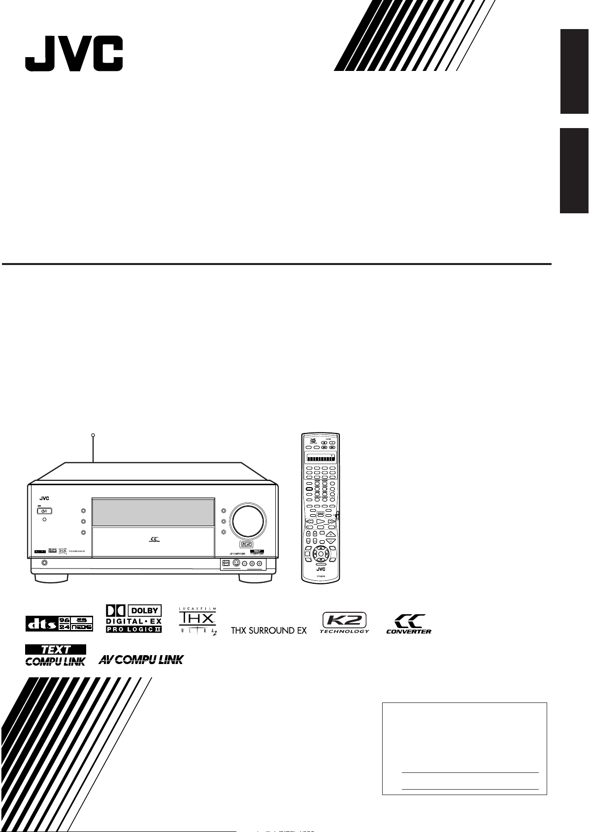
AUDIO/VIDEO CONTROL RECEIVER
RX-DP20V
STANDBY/ON
STANDBY
PHONES
DIMMER
CC CONVERTER
ZONE 1
ON/OFF
ZONE 2
ON/OFF
DOOR
UP
DOOR
DOWN
MASTER VOLUME
S-VIDEODIGITAL
VIDEO L—AUDIO—R
VIDEO
CHANNEL
TV/VIDEO
MUTING
DVD
ON/OFF ON/OFF
STANDBY/ON STANDBY/ON
STANDBY
TV/CATV/DBS
VCR 1
ON
DVD MULTI
CD
CDR
PHONO
TAPE/MD
EXT 7.1CH
ANALOG/DIGITAL
CC CONVERTER
EFFECT
LIVENESS
SOUND
TEST
THX
EX/ES/7.1
ANALOG DIRECT
SLEEP DIMMER
FM MODE
DSP SURR/DSPSURROUND
RETURN
100
+
OFF
INPUT
SET
SETUP
MENU
ADJUST
MENU
DVD
MENU
EXIT
TEXT
DISPLAY
123
456
7
/P
89
10
+
100
TV VOL
VOLUME
TUNING
STOP PAUSE
LIGHT
FF/
/ REW
REC
PLAY
DOWN UP
RM-SRXDP20J
REMOTE CONTROL
A/V CONTROL RECEIVER
VCR 1 VCR 2
FM/AMVIDEOTV/DBS
ZONE 2
TRANSMITLEARN
ZONE 1
ZONE 2
ZONE 1
ZONE 2 LEARNZONE 1
TV
CATV/
DBS
For Customer Use:
Enter below the Model No. and Serial
No. which are located either on the rear,
bottom or side of the cabinet. Retain this
information for future reference.
Model No.
Serial No.
AUDIO/VIDEO CONTROL RECEIVER
RECEPTEUR DE COMMANDE AUDIO/VIDEO
RX-DP20VBK
English
Français
INSTRUCTIONS
MANUEL D’INSTRUCTIONS
LVT0965-002B
[C]
Page 2
Warnings, Cautions and Others/
WARNING: TO REDUCE THE RISK OF FIRE
OR ELECTRIC SHOCK, DO NOT EXPOSE
THIS APPLIANCE TO RAIN OR MOISTURE.
CAUTION: TO REDUCE THE RISK OF ELECTRIC SHOCK.
DO NOT REMOVE COVER (OR BACK)
NO USER SERVICEABLE PARTS INSIDE.
REFER SERVICING TO QUALIFIED SERVICE PERSONNEL.
RISK OF ELECTRIC SHOCK
DO NOT OPEN
The lightning flash with arrowhead symbol,
within an equilateral triangle is intended to
alert the user to the presence of uninsulated
"dangerous voltage" within the product's
enclosure that may be of sufficient
magnitude to constitute a risk of electric
shock to persons.
The exclamation point within an equilateral
triangle is intended to alert the user to the
presence of important operating and
maintenance (servicing) instructions in the
literature accompanying the appliance.
CAUTION
23.5 kg / 52.0 lb.
Mises en garde, précautions et indications diverses
CAUTION
To reduce the risk of electrical shocks, fire, etc.:
1. Do not remove screws, covers or cabinet.
2. Do not expose this appliance to rain or moisture.
ATTENTION
Afin d’éviter tout risque d’électrocution, d’incendie, etc.:
1. Ne pas enlever les vis ni les panneaux et ne pas ouvrir le
coffret de l’appareil.
2. Ne pas exposer l’appareil à la pluie ni à l’humidité.
Caution–– (STANDBY/ON) switch!
Disconnect the mains plug to shut the power off completely. The
(STANDBY/ON) switch in any position does not disconnect
the mains line. The power can be remote controlled.
Attention––Commutateur (STANDBY/ON)!
Déconnecter la fiche de secteur pour couper complètement le
courant. Le commutateur (STANDBY/ON) ne coupe jamais
G-1
complètement la ligne de secteur, quelle que soit sa position. Le
courant peut être télécommandé.
CAUTION!
To avoid personal injury or accidentally
dropping the unit, have two persons unpack,
carry, and install the unit.
ATTENTION!
Pour éviter toute blessure personnelle ou
chute accidentelle de l’appareil, faites
déballer, transporter et installer l’appareil
par deux personnes.
Page 3

For Canada/pour le Canada
CAUTION: TO PREVENT ELECTRIC SHOCK, MATCH WIDE
BLADE OF PLUG TO WIDE SLOT, FULLY INSERT
ATTENTION: POUR EVITER LES CHOCS ELECTRIQUES,
INTRODUIRE LA LAME LA PLUS LARGE DE LA FICHE DANS LA
BORNE CORRESPONDANTE DE LA PRISE ET POUSSER
JUSQUAU FOND
For Canada/pour Le Canada
For the main unit / Pour l’appareil principal
THIS DIGITAL APPARATUS DOES NOT EXCEED THE CLASS B
LIMITS FOR RADIO NOISE EMISSIONS FROM DIGITAL
APPARATUS AS SET OUT IN THE INTERFERENCE-CAUSING
EQUIPMENT STANDARD ENTITLED “DIGITAL APPARATUS,”
ICES-003 OF THE DEPARTMENT OF COMMUNICATIONS.
CET APPAREIL NUMERIQUE RESPECTE LES LIMITES DE
BRUITS RADIOELECTRIQUES APPLICABLES AUX APPAREILS
NUMERIQUES DE CLASSE B PRESCRITES DANS LA NORME
SUR LE MATERIEL BROUILLEUR; “APPAREILS NUMERIQUES”,
NMB-003 EDICTEE PAR LE MINISTRE DES COMMUNICATIONS.
For the remote control / Pour la télécommande
This device complies with RSS-210 of Industry Canada Rules.
Operation is subject to the following two conditions: (1) this device
may not cause interference, and (2) this device must accept any
interference, including interference that may cause undesired
operation of the device.
Cet appareil est conforme au règlement CNR-210 de l’industrie du
Canada. L’utilisation de ce dispositif est autorisée seulement aux
conditions suivantes: (1) il ne doit pas produire de brouillage et (2)
l’utilisateur du dispositif doit être prêt à accepter tout brouillage
radioélectrique reçu, même si ce brouillage est susceptible de
compromettre le fonctionnement du dispositif.
G-2
Page 4

English
Features
Introduction
We would like to thank you for purchasing one of our JVC products.
Before operating this unit, read this manual carefully and thoroughly to obtain the best possible performance
from your unit, and retain this manual for future reference.
Precautions
THX Ultra2 certified
The newly introduced THX Ultra2 standard ensures the highest
sound and picture quality and the most reliable performance by
using seven-channel amplification to reproduce multi-channel
software. In newly developed THX Ultra2 Cinema Mode and
THX Music Mode, all multi-channel software (5.1 channels or
more) is automatically detected and proper processing is applied
to improve directional and ambient surround information through
four surround speakers—two at the side and two at the back.
Compatible with various audio formats including
DTS 96/24
RX-DP20VBK allows you to enjoy newly introduced audio
formats such as Dolby Digital EX, Dolby Pro Logic II, DTS-ES,
DTS NEO:6, and DTS 96/24.
• This unit is also compatible with Dual Mono signals recorded in
Dolby Digital and DTS discs.
7.1 channel DAP (Digital Acoustic Processor)
Sound field simulation technology allows precise ambience
recreation of existing theaters and halls. Thanks to the highperformance DSP (Digital Signal Processor) and high-capacity
memory, you can enjoy 7.1-channel surround by playing 2channel or multi-channel software.
Multi-channel headphone virtual surround
sound—3D HEADPHONE
The built-in headphone virtual surround system is compatible with
multi-channel software. You can enjoy a natural surround sound
through the headphones.
192 kHz/24 bit PEM DD audio DA converter
The JVC-exclusive converter is now upgraded to be fully
compatible with DVD Audio’s high specifications. Subtle nuances
are accurately reproduced.
K2 Technology
K2 technology has been designed to enable natural audio
reproduction, achieving a drastic reduction in digital distortion
and creating original sound ambience with high precision.
CC (Compensative Compression) Converter
CC Converter eliminates jitter and ripples, achieving a drastic
reduction in digital distortion by processing the digital music data
in 24 bit–quantization and by expanding the sampling frequency
to 128 kHz (for fs 32 kHz signals)/176.4 kHz (for fs 44.1 kHz
signals)/192 kHz (for fs 48 kHz signals). By using the CC
Converter, you can obtain a natural sound field from any source.
ZIST (Zero Interference audio Signal
Transmission) circuit
The ZIST circuit incorporated for the EXT 7.1 CH IN (input)
jacks successfully eliminates the video signal interference to the
audio signals by making the cold side of the audio signals
completely independent from the ground.
Multi-room operations
You can connect two pairs of front speakers to the
RX-DP20VBK, and use them to listen to different sources in
different rooms (Zone 1 and Zone 2) at the same time.
COMPU LINK/TEXT COMPU LINK/AV COMPU
LINK remote control systems
These COMPU LINK remote control systems allow you to
operate other JVC audio/video components from this receiver.
Power sources
• When unplugging the receiver from the wall outlet, always pull
the plug, not the AC power cord.
• Do not handle the AC power cord with wet hands.
• If you are not going to operate the receiver for an extended period
of time, unplug the AC power cord from the wall outlet.
Multi-room operations
• Do not use the remote control outdoors or install the speakers
outdoors.
• When operating the receiver from a place where you cannot see
the receiver (for example, when controlling the receiver installed
in the living room from the kitchen), pay attention to the following
not to surprise other people:
– Be careful not to turn up the volume too high when controlling
the receiver without listening to the playback sound.
– Be careful not to surprise other people with a sudden sound
coming out of the receiver when turning it on. (Stopping the
sound suddenly may surprise people as well.)
• If the receiver operates by itself or malfunctions, the following
causes should be considered:
– Interference to RF communication between the receiver and the
remote control from outside.
– The remote control is operated unintentionally. For example, a
book is placed on the remote control, possibly, depressing some
of its buttons.
• If your neighbour uses the same or similar RF remote control
system, the receiver may happen to receive the RF signals sent
from such an RF remote control system, which could cause your
receiver to be operated unintentionally. If this happens, set the
BAND selectors both on the rear and on the remote control to
another band (either BAND 1 or BAND 2)—see page 17 for
details.
If the problem still persists, stop using the RF rod antenna and the
remote control, and consult your JVC dealer or the nearest JVC
Service Center.
Ventilation
The seven high power amplifiers built in this receiver will generate
heat inside the cabinet.
For safety, observe the following carefully:
• Make sure there is good ventilation around the receiver. Poor
ventilation could overheat and damage the receiver.
• Do not block the ventilation openings or holes. (If the ventilation
openings or holes are blocked by a newspaper or cloth, etc., the
heat may not be able to get out.)
Others
• Should any metallic object or liquid fall onto the unit, unplug the
unit and consult your dealer before operating any further.
• Do not use this receiver in a bathroom or places with water.
• Do not place any containers filled with water or liquids (such as
cosmetics or medicines, flower vases, potted plants, cups, etc.) on
top of this receiver.
• Do not disassemble the unit since there are no user serviceable
parts inside.
If anything goes wrong, unplug the AC power cord and consult your
JVC dealer.
1
Page 5

Table of Contents
Parts Identification ...................................... 3
Getting Started ........................................... 7
Before Installation ...................................................................... 7
Checking the Supplied Accessories ........................................... 7
Connecting the FM and AM Antennas ....................................... 7
Connecting the Speakers ............................................................ 8
Connecting Audio/Video Components ..................................... 11
7 Analog Connections ............................................................. 11
7 Digital Connections .............................................................. 16
Using the RF Rod Antenna and IR Signal Transmitter ............ 17
Connecting the Power Cord ..................................................... 18
Putting Batteries in the Remote Control .................................. 18
Multi-Room Operations............................... 19
Required Connections for Zone 2 ............................................ 19
Basic Operating Procedure for Zone 1 ..................................... 20
Basic Operating Procedure for Zone 2 ..................................... 21
Zone 1 (Main Room) Operations .................. 22
Turning the Power On and Off (Standby) ................................ 22
Canceling the Zone 1 Operations ............................................. 23
Selecting the Zone 1 Source to Play ........................................ 23
Adjusting the Zone 1 Volume ................................................... 24
Activating the Zone 1 Front Speakers ...................................... 25
Selecting the Analog or Digital Input Mode ............................ 25
Attenuating the Input Signal .................................................... 26
Muting the Zone 1 Sound ......................................................... 26
Changing the Display Brightness ............................................. 27
Turning Analog Direct On and Off .......................................... 27
Making Sounds Natural ............................................................ 27
Changing the Source Name ...................................................... 27
Using the Sleep Timer .............................................................. 28
Zone 2 (Sub-room) Operations .................... 29
Turning the Power On and Off (Standby) and Selecting
the Zone 2 Operations ........................................................ 29
Canceling the Zone 2 Operations ............................................. 30
Selecting the Zone 2 Source to Play ........................................ 31
Adjusting the Zone 2 Volume ................................................... 31
Activating the Zone 2 Front Speakers ...................................... 32
Muting the Zone 2 Sound ......................................................... 32
Receiving Radio Broadcasts ........................ 33
Tuning in to Stations Manually ................................................ 33
Using Preset Tuning ................................................................. 34
Selecting the FM Reception Mode ........................................... 34
8 Selecting the Dual Mono Sound—DUAL MONO ............... 42
9 Setting the Digital Input/Output Terminals
—DIGITAL IN/OUT .......................................................... 42
p Setting the Video Input Terminals—VIDEO INPUT .......... 43
q Turning On and Off the Video Output—VIDEO POWER ........ 43
w Setting the Zone 2/Speakers 2 Usage
—ZONE 2/SPEAKER 2 ..................................................... 43
e Superimposing the Menus—SUPERIMPOSE .................... 44
r Showing the Text Information on the Display
—FL DISPLAY ................................................................... 44
t Memorizing the Volume Level for Each Source
—ONE TOUCH OPE ......................................................... 44
Sound Adjustments.................................... 45
Adjustment Menu Configuration ............................................. 45
Operation through On-Screen Display Menus ......................... 46
Menu Operating Procedure ...................................................... 47
1 Adjusting the Parametric Equalizer for Each Channel
—PEQ FRONT/CENTER/SURROUND/SURR BACK .......... 48
2 Setting the Midnight Mode—MIDNIGHT MODE ............ 49
3 Adjusting the Various Effects—EFFECT ADJUST ............ 49
Using the Surround and THX Modes ...................
Reproducing Theater Ambience ............................................... 51
Introducing the Surround and THX Modes.............................. 51
Surround and THX Modes Applicable to the Various Software .....
Activating the Surround and THX Modes ............................... 55
7 Activating the 7.1-channel reproduction ............................. 55
7 Activating the Surround Modes ........................................... 56
7 Activating the THX Modes .................................................. 57
Using the DSP Modes .......................................
Reproducing the Sound Field ................................................... 58
Introducing the DSP Modes ..................................................... 58
Activating the DSP Modes ....................................................... 59
Using the Analog Multi-channel Playback Mode .....
Activating the Analog Multi-channel Playback Modes .............. 60
51
53
58
60
COMPU LINK Remote Control System ......... 61
TEXT COMPU LINK Remote Control System .....
7 Showing the Disc Information on the TV Screen
(Either in Zone 1 or in Zone 2) ............................................. 64
7 Searching for a Disc (Only for the CD player) ..................... 65
7 Entering the Disc Information .............................................. 66
63
AV COMPU LINK Remote Control System .... 68
English
Basic Settings ........................................... 35
Setup Menu Configuration ....................................................... 35
Operation through On-Screen Display Menus ......................... 36
Menu Operating Procedure ...................................................... 37
1 Setting the Speakers—SPEAKER SETTING ..................... 38
2 Adjusting the Speaker Channel Output Levels
—CHANNEL LEVEL ........................................................ 38
3 Setting the Speaker Distance—SPEAKER DISTANCE ... 40
4 Setting the Bass Sounds—SUBWOOFER .......................... 40
5 Setting the THX Audio—THX AUDIO SETUP................... 41
6 Setting the Surround Channel Output Speakers
—SURR CH OUT............................................................... 42
7 Setting the Audio Delay Level—AUDIO DELAY ................ 42
Operating JVC’s Audio/Video Components ... 71
Operating Audio Components .................................................. 71
Operating Video Components .................................................. 73
Operating Other Manufacturers’ Equipment ... 74
Changing the Preset Signal Codes ........................................... 74
Storing the Remote Signals Manually ...................................... 78
Troubleshooting ......................................... 81
Specifications ............................................ 83
Indicates the functions YOU CAN ALSO USE when
the receiver is ready for Zone 2 operations.
2
Page 6
o
a;
d
g
f
s
j
l
k
z
STANDBY/ON
STANDBY
SPEAKERS 1
PHONES
AUDIO/VIDEO CONTROL RECEIVER
SURROUNDTHX
RIGHT
/ PRESET 5
EXIT
/ FM MODE
LEFT
/ PRESET ∞
UP
/ TUNING 5
SET
/ MEMORY
DOWN
/ TUNING ∞
SURR/DSP
OFF
SPEAKER 2
/ ZONE 2
INPUT MODE
/ INPUT ATT
ZONE 2
CONTROL
EX/ES/7.1 DSP
ANALOG
DIRECT
ADJUST MENU
SETUP MENU
DIMMER
CC CONVERTER
ZONE 1
ON/OFF
ZONE 2
ON/OFF
DOOR
UP
DOOR
DOWN
MASTER VOLUME
RX-DP20V
S-VIDEODIGITAL
VIDEO L—AUDIO—R
VIDEO
DVD DVD MULTI VCR 1 VCR 2 TV/DBS CDVIDEO PHONO TAPE/MD CDR FM/AM EXT 7.1CH
1 2 3 4 5 6 7 8 9
iuytrewqp
/
h
x
SPEAKERS 1 SURROUND
THX
RIGHT
/ PRESET 5
EXIT
/ FM MODE
LEFT
/ PRESET ∞
UP
/ TUNING 5
SET
/ MEMORY
DOWN
/ TUNING ∞
SURR/DSP
OFF
ANALOG
DIRECT
SPEAKERS 2
/ ZONE 2
INPUT MODE
/ INPUT ATT
ZONE 2
CONTROL
EX/ES/7.1 DSP
ADJUST MENU
SETUP MENU
DOOR
DOWN
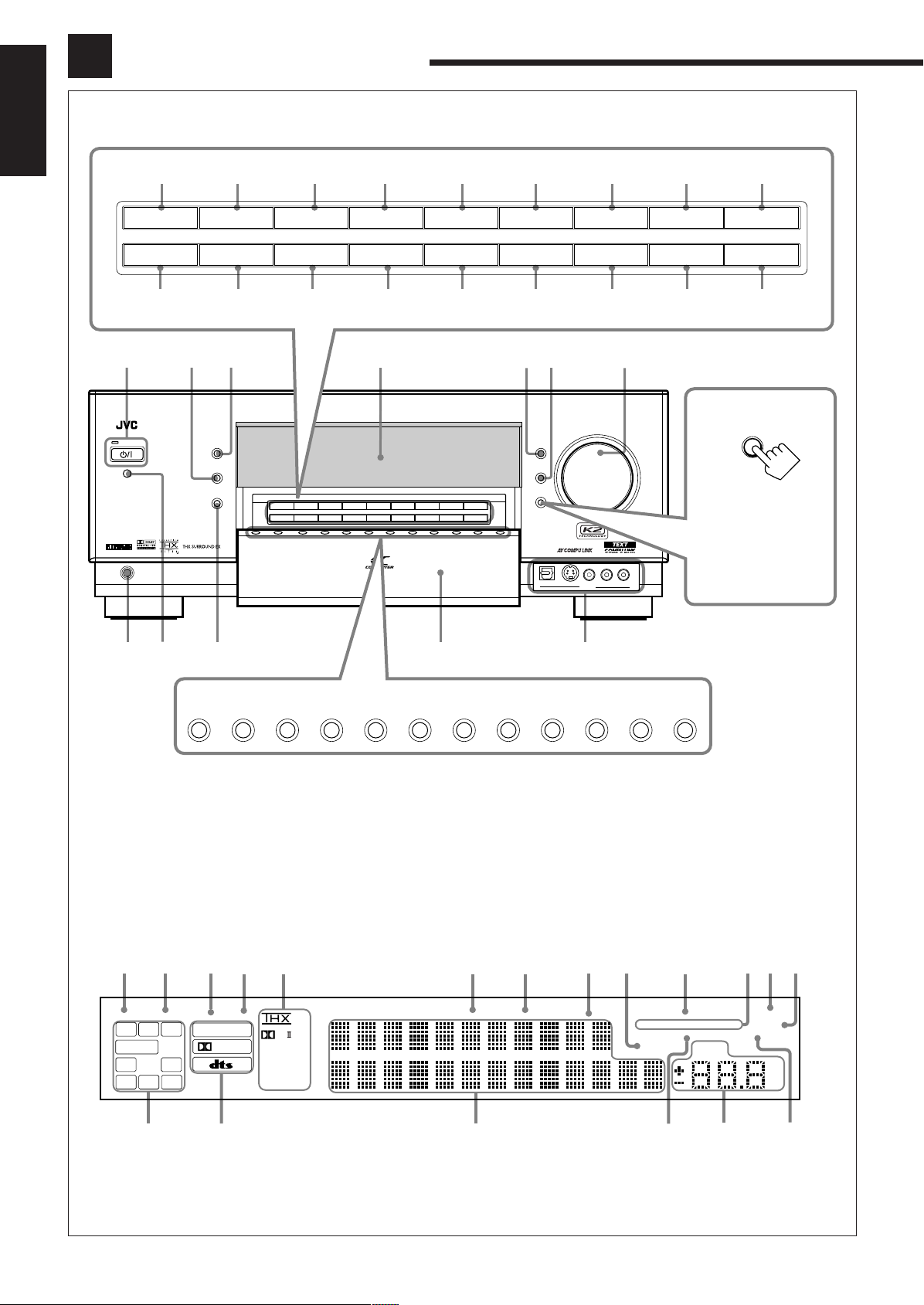
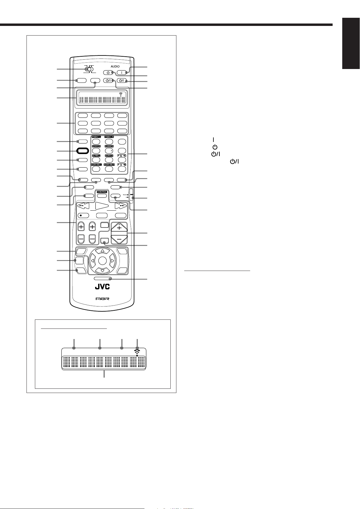
Front Panel
4
1
!
L
DGTL AUTO 96/24
DUAL ANALOG
STEREO
TUNED
LINEAR PCM
Neo:6
DSP
DIGITAL
3D-PHONIC
ONE TOUCH OPERATION
SLEEP
SPEAKERS
PARAMETRICEQ
MIDNIGHT
VOLUME
INPUT
ATT
MODE
ZONE 2 BI-AMP
12
HEADPHONE
SUBWFR
C R
LFE
RS
S
LS
SB
dB
AUTO MUTING
2
3
5
6
7
8
9
0
=-~
^%
$#
@
PL
English
Parts Identification
Display Window
To open the front door,
press DOOR DOWN.
(For more details, see
page 20.)
3
Page 7

Refer to the pages in parentheses for details.
Front Panel
1 SPEAKERS 1 button (20, 25)
2 INPUT MODE button (25)
INPUT ATT button (26)
3 THX button (57, 60)
4 SURROUND button (56, 57)
5 SURR/DSP OFF button (56, 57, 59, 60)
6 ADJUST MENU button (46)
7 DOWN button (36, 46)
TUNING ∞ button (33)
8 UP button (36, 46)
TUNING 5 button (33)
9 SET button (36, 46)
MEMORY button (34)
p SPEAKERS 2 button (20, 25)
ZONE 2 button (32)
q ZONE 2 CONTROL button (21, 29)
w EX/ES/7.1 button (55)
e DSP button (59)
r ANALOG DIRECT button (27)
t SETUP MENU button (36)
y LEFT button (36, 46)
PRESET ∞ button (34)
u RIGHT button (36, 46)
PRESET 5 button (34)
i EXIT button (36, 46)
FM MODE button (34)
o
; ZONE 1 ON/OFF button and lamp (20–22)
a CC CONVERTER button and lamp (27)
s Display
d DIMMER button (27)
f DOOR UP button (20)
g MASTER VOLUME control (20, 21, 24, 31)
h DOOR DOWN button (20)
j PHONES jack (25)
k Remote sensor
l ZONE 2 ON/OFF button and lamp (21, 29, 30)
/ Source selecting buttons (20, 23–25)
z Front door
x VIDEO input terminals (12)
(STANDBY/ON) button and STANDBY lamp
(20–22, 29)
• STANDBY lamp lights up in red when the unit is turned off.
• ZONE 1 ON/OFF lamp lights up in red when Zone 1 is
turned on.
• CC CONVERTER lamp lights up in red when CC Converter
is turned on.
• ZONE 2 ON/OFF lamp lights up in red when Zone 2 is
turned on.
• DVD, DVD MULTI, VCR 1, VCR 2, TV/DBS, VIDEO, CD,
PHONO, TAPE/MD, CDR, FM/AM, EXT 7.1CH
Display Window
1 DUAL indicator (24)
• Lights up when Dual Mono signals are detected.
2 ANALOG indicator (26)
• Lights up when an analog input (source) is selected.
3 DGTL AUTO indicator (26)
• Lights up when auto digital input (DIGITAL AUTO) is
selected.
4 96/24 indicator (52)
• Lights up when DTS 96/24 signals are detected.
5 Surround/THX/DSP mode indicators
• Indicate the current Surround/THX/DSP mode setting.
6 TUNED indicator (33)
• Lights up when a station is received.
7 STEREO indicator (33)
• Lights up when an FM stereo station is received.
8 AUTO MUTING indicator (34)
• Lights up when the FM station reception mode is set to Auto
Reception mode (AUTO MUTING).
9 INPUT ATT indicator (26)
• Lights up when Input Attenuator is in use.
0 ONE TOUCH OPERATION indicator (44)
• Lights up when One Touch Operation is in use.
- SPEAKERS 1/2/ZONE 2 indicators (32)
• SPEAKERS : Lights up when any of the speakers connected to
the FRONT 1 SPEAKERS and the FRONT 2/
ZONE 2 SPEAKERS terminals is activated.
• 1/2 : Lights up when the corresponding speakers are
activated for Zone 1.
• ZONE 2 : Lights up when the front speakers connected to
the FRONT 2/ZONE 2 SPEAKERS terminals
are activated for Zone 2.
= SLEEP indicator (28)
• Lights up when Sleep Timer is in use.
~ BI-AMP indicator (44)
• Lights up when “SPEAKER 2” is set to “BI-AMP OUT.”
! Speaker and signal indicators (23)
• Speaker indicators : Indicate the activated speakers.
• Signal indicators : Indicate the incoming channel signals.
@ Digital signal format indicators (26)
• Indicates the digital signal format of incoming signals.
# Main display
• Shows the source name, station frequency, Surround/THX/
DSP mode, etc.
$ PARAMETRIC EQ indicator (48)
• Lights up when Parametric Equalizer is in use.
% VOLUME level indicator
• Indicates the volume level.
• Goes off while muting sounds.
^ MIDNIGHT MODE indicator (49)
• Lights up when Midnight Mode is in use.
English
4
Page 8
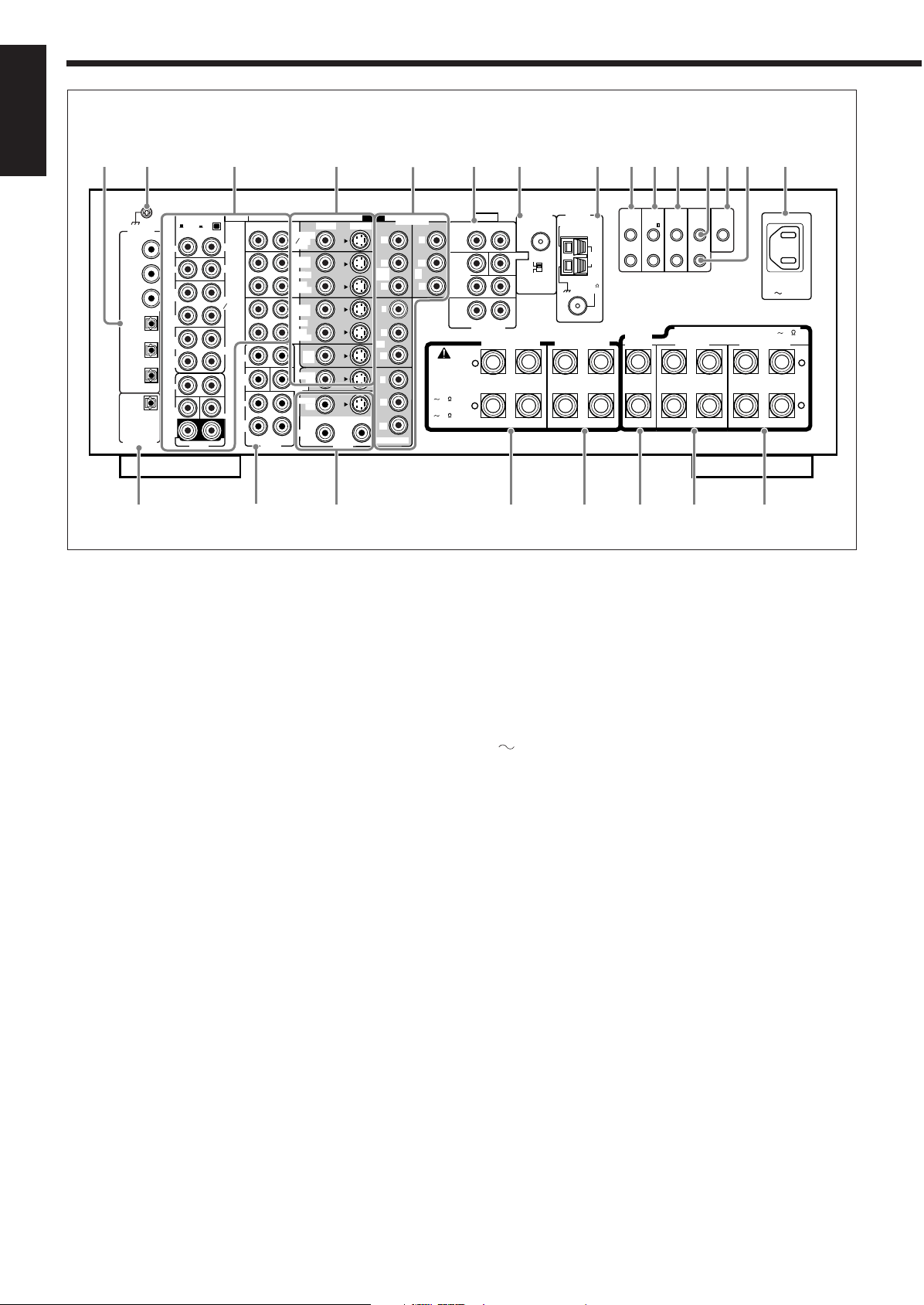
Rear Panel
EXT 7.1CH IN
R
L
RIGHT
LEFT
SURR
BACK
SUB
WOOFER
SURR
FRONT
CENTER
ANTENNA
RF REMOTE
RIGHTMMLEFT
PHONO
CD
CDR
TAPE
MD
OUT
(REC)
IN
(PLAY)
OUT
(REC)
FRONT
CENTER
L
R
IN
(PLAY)
SUB
WOOFER
VIDEO
RIGHT LEFT
DVD
IN
TV SOUND
DBS
IN
OUT
(REC)
IN
(PLAY)
VCR 1
L
R
VCR 2
S-VIDEO
VIDEO
Y
P
B
P
R
1 IN
(DVD)
Y
P
B
P
R
3 IN
Y
P
B
P
R
MONITOR OUT
Y
P
B
P
R
2
IN
PREOUT
SURR
BACK
SUB
WOOFER
SURR
FRONT
IN
(PLAY)
OUT
(REC)
COMPONENT
AUDIO AUDIO
ZONE 2
SURR
(REAR)
MC
DIGITAL IN
1 (DVD)
2 (CD)
3 (TV
/DBS)
4 (CDR)
5 (MD)
6 (VCR 1)
PCM
/ DOLBY DIGITAL
/ DTS
DIGITAL OUT
CENTER
BAND1
BAND2
FM 75
COAXIAL
ANTENNA
AM
EXT
AM
LOOP
RIGHT
LEFT
+
–
+
–
CAUTION :
SPEAKER
IMPEDANCE
FRONT 1 SPEAKERS
FRONT 2 /
ZONE 2 SPEAKERS
RIGHT
LEFT
CENTER
SPEAKER
RIGHT
LEFT
RIGHT
LEFT
SURROUND BACK
SPEAKERS
SURROUND
SPEAKERS
816
FRONT 1 AND 2
/ ZONE 2:
416
FRONT 1 OR 2:
COMPU
LINK-4
(SYNCHRO)
AV
COMPU
LINK-
TEXT
COMPU
LINK
IR
OUT
IR
IN
CTRL
OUT
+12V
10mA MAX
AC IN
LR
MONITOR
OUT
PREOUT
MONITOR
OUT
DVD IN
IN
IN
23 456789pqert
yui o;asd
w1
816
CAUTION : SPEAKER IMPEDANCE
English
1 DIGITAL IN terminals (16)
• Coaxial: 1 (DVD), 2 (CD), 3 (TV/DBS)
• Optical: 4 (CDR), 5 (MD), 6 (VCR 1)
2 Earth (ground) terminal (11)
3 Audio input/output jacks (13–15)
• Input: PHONO IN, CD IN, TAPE/MD IN, CDR IN
TV SOUND/DBS IN, VCR 1 IN, VCR 2 IN, DVD IN (5.1 ch)
• Output: TAPE/MD OUT, CDR OUT
VCR 1 OUT, VCR 2 OUT
4 S-video/composite video input/output jacks (13–15)
• Input: TV SOUND/DBS IN, VCR 1 IN, VCR 2 IN, DVD IN
• Output: VCR 1 OUT, VCR 2 OUT, MONITOR OUT
5 Component video input/output jacks (13–15)
• Input: 1 IN (DVD), 2 IN, 3 IN
• Output: MONITOR OUT
6 EXT 7.1CH IN (audio input) jacks (12)
7 RF REMOTE ANTENNA terminal and BAND 1/2 selector
(17)
8 FM/AM ANTENNA terminals (7, 8)
9 COMPU LINK-4 (SYNCHRO) terminals (61, 63)
p AV COMPU LINK-III terminals (68)
q TEXT COMPU LINK terminals (63)
w IR OUT terminal (18, 68)
e CTRL OUT +12V terminal
• This terminal is only for service use.
r IR IN terminal
• This terminal is only for service use.
t
AC IN socket (18)
y DIGITAL OUT terminal (16)
u PREOUT jacks (10)
• FRONT, SUBWOOFER, CENTER, SURR, SURR BACK
i ZONE 2 audio/video output jacks (19)
• Audio output: PREOUT
• Video output: MONITOR OUT (S-video/composite video)
o FRONT 1 SPEAKERS terminals (9)
; FRONT 2/ZONE 2 SPEAKERS terminals (9, 19)
a CENTER SPEAKER terminals (9)
s SURROUND SPEAKERS terminals (9)
d SURROUND BACK SPEAKERS terminals (9)
5
Page 9
r
p
q
6
9
8
5
e
u
t
y
1
4
2
3
k
l
/
g
f
d
s
j
i
o
;
a
w
h
7
CHANNEL
TV/VIDEO
MUTING
DVD
ON/OFF ON/OFF
STANDBY/ON STANDBY/ON
STANDBY
TV/CATV/DBS VCR 1
ON
DVD MULTI
CD
CDR
PHONO
TAPE/MD
EXT 7.1CH
ANALOG/DIGITAL
CC CONVERTER
EFFECT
LIVENESS
SOUND
TEST
THX
EX / ES / 7.1
ANALOG DIRECT
SLEEP DIMMER
FM MODE
DSP SURR / DSPSURROUND
RETURN
100
+
OFF
INPUT
SET
SETUP
MENU
ADJUST
MENU
DVD
MENU
EXIT
TEXT
DISPLAY
123
456
7
/P 89
10
+
100
TV VOL
VOLUME
TUNING
STOP PAUSE
LIGHT
FF/
/ REW
REC
PLAY
DOWN UP
RM-SRXDP20J REMOTE CONTROL
A/V CONTROL RECEIVER
VCR 1 VCR 2
FM/AMVIDEOTV/DBS
ZONE 2
TRANSMITLEARN
ZONE 1
ZONE 2
ZONE 1
ZONE 2 LEARNZONE 1
TV
CATV/
DBS
5
1
2
3
4
ZONE 2 LEARNZONE 1
Remote Control
Remote’s display window
1 ZONE 1/ZONE 2 (LEARN/TRANSMIT) selector
2 ZONE 1 ON/OFF button (23)
3 ZONE 2 ON/OFF button (30)
4 Display window
5 Source selecting buttons (20, 21, 23–25, 71–76, 78–80)
6 ANALOG/DIGITAL INPUT button (25, 71)
• DVD, DVD MULTI, PHONO, CD, VCR 1, VCR 2,
TAPE/MD, CDR, TV/DBS, VIDEO, FM/AM, EXT 7.1CH
7 SOUND button (39, 50, 56, 59, 71)
8 TEST button (39, 71)
9 CC CONVERTER button (27, 71)
p THX button (57, 71)
q SURROUND button (56, 57, 71)
w EX/ES/7.1 button (55, 71)
e SLEEP button (28)
r Operating buttons for audio/video components
(72–76, 79, 80)
t On-screen operation buttons (36, 46, 64)
• SETUP MENU, ADJUST MENU, SET, EXIT, % (UP),
fi (DOWN), @ (LEFT), # (RIGHT)
y TEXT DISPLAY button (64)
u DVD MENU button (73, 76)
i AUDIO
o AUDIO
; VCR 1
a TV/CATV/DBS
(ON) button (20–22, 30, 76)
(STANDBY) button (22, 30, 76)
(STANDBY/ON) button (73, 75, 80)
(STANDBY/ON) button (73–75, 79)
s • 10 keys for selecting preset channels (34, 71)
• 10 keys for adjusting sound (39, 56, 71)
• 10 keys for adjusting DSP effects (50, 59, 71)
• 10 keys for operating audio/video components
(71–80)
d SURR/DSP OFF button (56, 57, 59, 60, 71)
f DSP button (59, 71)
g ANALOG DIRECT button (27, 71)
h TV operation mode selector (73–75, 79)
j DIMMER button (27)
k VOLUME +/– buttons (20, 21, 24, 31)
l MUTING button (26, 32)
/ LIGHT button (18)
Remote’s display window
1 ZONE 1 indicator
• Lights up when you press a button on the remote control,
with the ZONE 1/ZONE 2 (LEARN/TRANSMIT) selector
set to “ZONE 1.” This remote control can be used only for
Zone 1 operations.
2 ZONE 2 indicator
• Lights up when you press a button on the remote control,
with the ZONE 1/ZONE 2 (LEARN/TRANSMIT) selector
set to “ZONE 2.” This remote control can be used only for
Zone 2 operations.
3 LEARN indicator
• Lights up when the ZONE 1/ZONE 2 (LEARN/TRANSMIT)
selector is set to “LEARN.” This remote control cannot
operate the receiver or other components, but can memorize
IR signals. (See page 78.)
4 Signal transmission indicator
• Lights up when transmitting the remote control signals.
5 Remote control operation mode display
• Remote control operation mode such as “DVD,” “CD,”
“SOUND,” etc. appears.
When the remote control operation mode changes, it is
shown on this display for about 10 seconds.
(When showing the remote control operation mode just for
confirmation, it is shown only for about 5 seconds—e.g.
when pressing Number button 1 while the remote control
operation mode is “CD,” “CD” appears for about 5 seconds.)
English
6
Page 10
Getting Started
FM 75
COAXIAL
ANTENNA
AM
EXT
AM
LOOP
AM
LOOP
ANTENNA
AM
EXT
FM 75
COAXIAL
AM
LOOP
ANTENNA
AM
EXT
FM 75
COAXIAL
AM
LOOP
This section explains how to connect audio/video components and speakers to the receiver, and how to connect the
power supply.
English
Before Installation
General
• Be sure your hands are dry.
• Turn the power off on all components.
• Read the manuals supplied with the components you are going to
connect.
Location
• Install the receiver in a location that is level, well-ventilated and
free from moisture.
• The temperature around the receiver must be between –5˚C and
35˚C (23˚F and 95˚F).
• Make sure there is good ventilation around the receiver. Poor
ventilation could overheat and damage the receiver.
Handling the receiver
• Do not insert any metal object into the receiver.
• Do not disassemble the receiver or remove screws, covers, or
cabinet.
• Do not expose the receiver to rain or moisture.
Checking the Supplied Accessories
Check to be sure you have all of the following items, which are
supplied for the receiver.
The number in parentheses indicates the quantity of each piece
supplied.
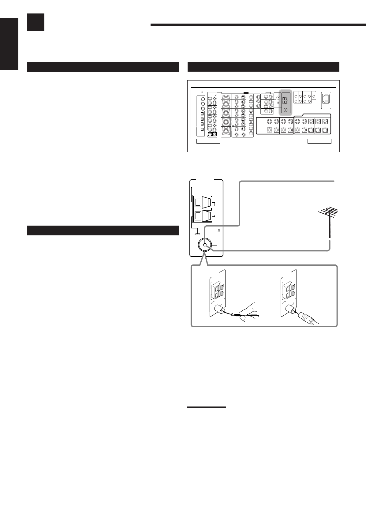
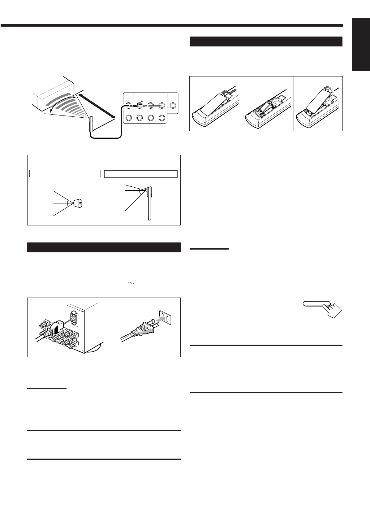
Connecting the FM and AM Antennas
Rear view
FM Antenna Connections
Extend the supplied FM antenna horizontally.
FM Antenna
(supplied)
Outdoor FM Antenna Cable
(not supplied)
• Remote Control (1)
• Batteries (2)
• AM Loop Antenna (1)
• FM Antenna (1)
• RF Rod Antenna (1)
• IR Signal Transmitter (1)
• Double-Sided Adhesive Tape (1)
• Front Terminal Cover (1)
• AC Power Cord (1)
If any item is missing, contact your dealer immediately.
A
B
A. Using the Supplied FM Antenna
The FM antenna provided can be connected to the FM 75Ω
COAXIAL terminal as a temporary measure.
B. Using the Standard Type Connector with an Outdoor FM
Antenna (not Supplied)
A standard type connector should be connected to the FM 75Ω
COAXIAL terminal.
Note:
If reception is poor, connect an outdoor antenna.
Before attaching a 75
to an outdoor antenna), disconnect the supplied FM antenna.
Ω
coaxial cable (the kind with a round wire going
7
Page 11
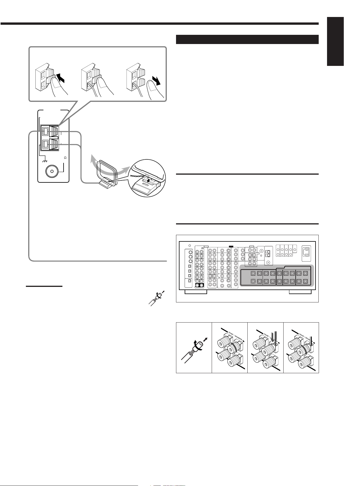
AM Antenna Connections
FM 75
COAXIAL
ANTENNA
AM
EXT
AM
LOOP
2
3
1
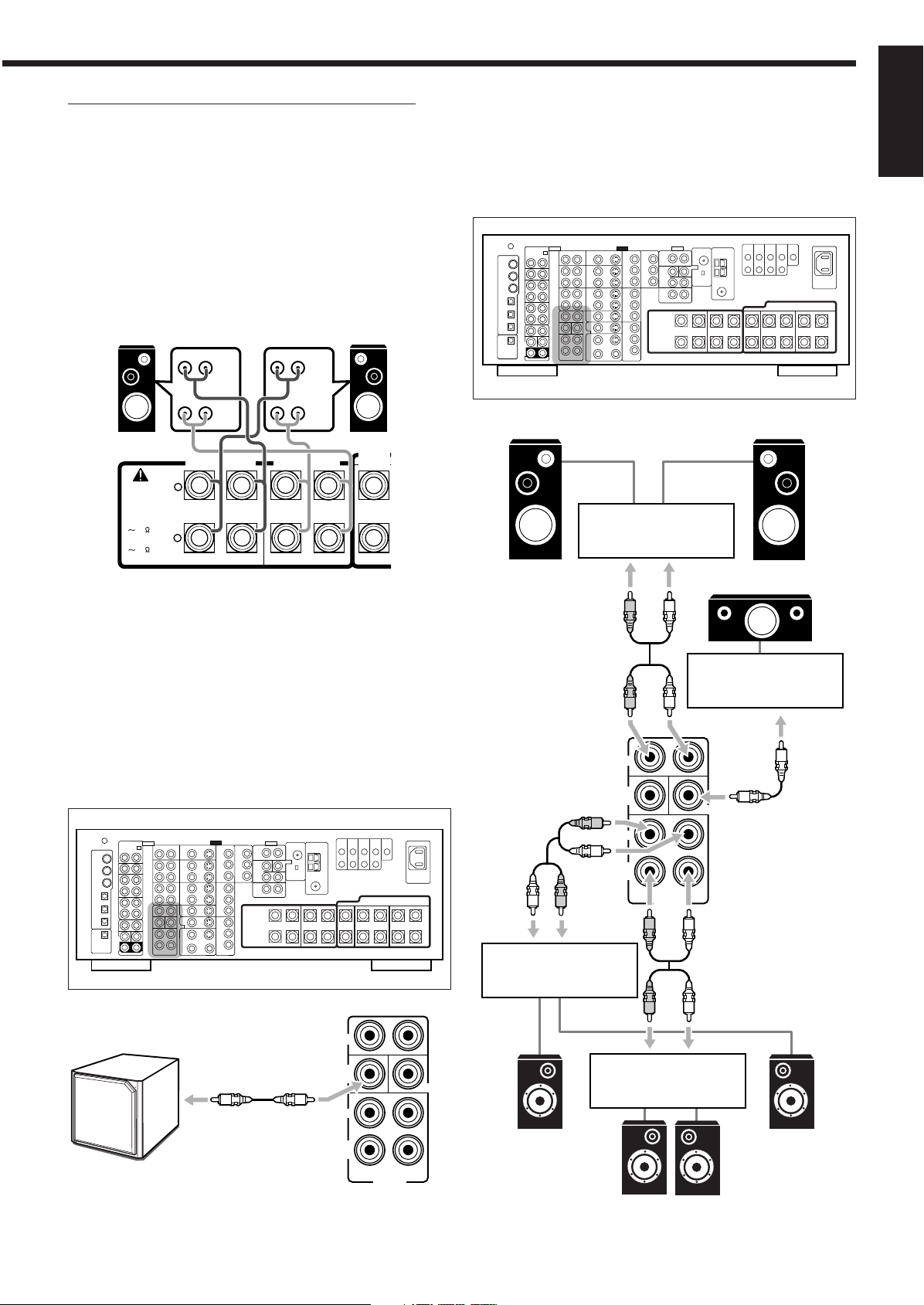
Connecting the Speakers
Turn the loop until you
have the best reception.
AM Loop Antenna
(supplied)
Snap the tabs on the loop into
the slots of the base to
assemble the AM loop.
For full enjoyment of the THX modes (see page 51), it is
recommended to use THX-certified speakers.
You can connect the following speakers:
• Two pairs of front speakers to produce normal stereo sound.
• One pair of surround speakers to produce a three-dimensional
sound movement and environmental background-effect sounds.
• One or one pair of surround back speakers to enjoy 6.1-channel or
7.1-channel sound reproduction. A pair of the speakers is required
to use THX Ultra2 Cinema and THX Music modes.
• One center speaker to produce a rich sound image by stabilizing
the sound localization (also used to emphasize human voices).
• One powered subwoofer to enhance the bass and to reproduce the
LFE channel recorded in multi-channel software.
For each speaker (except for a subwoofer), connect the (+) and (–)
terminals on the rear panel to the (+) and (–) terminals marked on
the speakers. For connecting a subwoofer, see page 10.
CAUTIONS:
Use only the speakers of the SPEAKER IMPEDANCE indicated by
the speaker terminals.
• When connecting to both of the FRONT 1 and FRONT 2 / ZONE
2 SPEAKERS terminals, use speakers with an impedance of
8 Ω to 16 Ω.
• When connecting to either the FRONT 1 or FRONT 2 / ZONE 2
SPEAKERS terminals, use speakers with an impedance of
4 Ω to 16 Ω.
English
Outdoor single vinyl-covered wire (not supplied)
Notes:
• If the AM loop antenna wire is covered with vinyl,
remove the vinyl by twisting it as shown in the diagram.
• Make sure the antenna conductors do not touch any
other terminals, connecting cords and power cord. This
could cause poor reception.
• If reception is poor, connect an outdoor single vinyl-covered wire to
the AM EXT terminal. (Keep the AM loop antenna connected.)
Rear view
Basic connecting procedure
1
2
3
4
1 Cut, twist, and remove the insulation at the end of
each speaker signal cable (not supplied).
2 Turn the knob counterclockwise.
3 Insert the speaker signal cable.
4 Turn the knob clockwise.
Continued on the next page.
8
Page 12
English
RIGHT
LEFT
+
–
+
–
CAUTION :
SPEAKER
IMPEDANCE
FRONT 1 SPEAKERS
FRONT 2 /
ZONE 2 SPEAKERS
RIGHT
LEFT
CENTER
SPEAKER
RIGHT
LEFT
RIGHT
LEFT
SURROUND BACK
SPEAKERS
SURROUND
SPEAKERS
816
FRONT 1 AND 2
/ ZONE 2:
416
FRONT 1 OR 2:
816
CAUTION : SPEAKER IMPEDANCE
C
LR
LS RS
LSB
RSB
30˚
90˚
60˚ 60˚
90˚
30˚
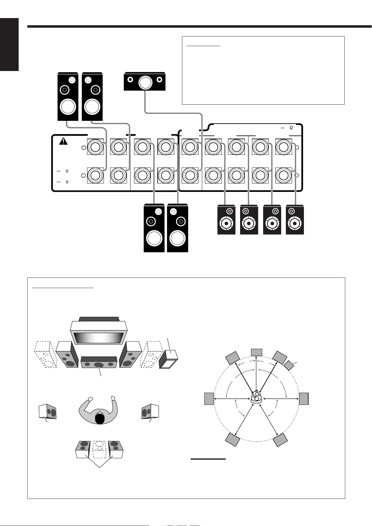
Front speakers 1
Right / Left
Center speaker
IMPORTANT:
After connecting the speakers, set the speaker setting
information properly:
• To obtain the best possible Surround/THX/DSP effect in Zone 1,
see “Basic Settings” on pages 35 to 44.
• To connect the speakers to the FRONT 2/ZONE 2 SPEAKERS
terminals, set the speaker usage correctly.
(See “w Setting the Zone 2/Speakers 2 Usage—ZONE 2/
SPEAKER 2” on page 43.)
Zone 1 speaker layout
Ideal speaker layout varies depending on the conditions of your
listening room. The diagram below is a recommended typical
example.
Left front speaker(s)
(L)
Center speaker
(C)
Left surround
speaker (LS)
Surround back speakers (LSB/RSB)
Right / Left
Front speakers 2
Subwoofer
Right front speaker(s)
(R)
Right surround
speaker (RS)
Front speakers and center speaker
• Place these speakers (position of the mid-range speaker units) at
the same height from the floor.
• Place these speakers aiming at the listener’s ears.
Surround and surround back speakers
• Place these speakers at a position which is 1 meter higher than
the listener’s ears.
• Point these speakers down aiming at the listener’s ears.
Note:
Ideal speaker layout requires that all speakers be placed at the
same distance from the listener. However, since in some places it
may be difficult to fulfil this requirement, this unit can adjust the
delay time so that the sounds through all the speakers reach the
listener with the same timing. (See page 40.)
Right / Left
Surround speakers
*
When using only one surround back speaker,
connect it to the LEFT terminals.
Right / Left
Surround back
speakers*
Subwoofer
9
Page 13
About the FRONT 2/ZONE 2 SPEAKERS terminals
L
R
PREOUT
SURR
BACK
SUB
WOOFER
SURR
FRONT
CENTER
RL
R
L
R
L
R
L
R
L
R
L
R
L
RIGHT
LEFT
+
–
CAUTION :
SPEAKER
IMPEDANCE
FRONT 1 SPEAKERS
FRONT 2 /
ZONE 2 SPEAKERS
RIGHT
LEFT
CENTER
SPEAKER
816
FRONT 1 AND 2
/ ZONE 2:
416
FRONT 1 OR 2:
HIGH
LOW
HIGH
LOW
L
R
PREOUT
SURR
BACK
SUB
WOOFER
SURR
FRONT
CENTER
The FRONT 2/ZONE 2 SPEAKERS terminals can be used as
follows:
• To connect the second pair of the front speakers in Zone 1.
• To connect the front speakers in Zone 2 when using the multi-
room operations (see page 19).
• To connect the front speakers in Zone 1 and to drive them using
two amplifiers built in this receiver.
If the speakers connected are of the bi-wiring connection type, you
can connect the speakers as illustrated below. (You can use either
front speaker terminals for high frequency or for low frequency
terminals.)
Enhance your audio system
You can use this receiver as the pre-amplifier (control amplifier)
when you connect power amplifiers to the PREOUT jacks on the
rear panel, using cables with RCA pin plugs (not supplied).
• Connect the white plug to the audio left jack, and the red plug to
the audio right jack.
English
Left Front speaker
Rear view
Right Front speaker
To use the speaker with the above connection, see “w Setting the
Zone 2/Speakers 2 Usage—ZONE 2/SPEAKER 2” on pages
43 and 44.
• When this connection is used, you cannot use the surround back
speakers. (In this case, no sounds come out of the SURR BACK
PREOUT jacks.)
Connecting a subwoofer
You can enhance the bass by connecting a subwoofer.
Connect the input jack of a powered subwoofer to the
SUBWOOFER PREOUT jack on the rear panel, using a cable with
RCA pin plugs (not supplied).
Left front speaker
Rear view
Right front speaker
Power amplifier
Center speaker
Power amplifier
subwoofer
Powered
Rear view
Power amplifier
Left surround
speaker
Power amplifier
Right surround
speaker
Left / Right
surround back speakers
10
Page 14
R
L
Connecting Audio/Video Components
RIGHTMMLEFT
PHONO
CD
TAPE
MD
OUT
(REC)
AUDIO
MC
IN
IN
R
L
CD
CDR
TAPE
MD
OUT
(REC)
IN
(PLAY)
OUT
(REC)
IN
R
L
R
L
CDR
TAPE
MD
OUT
(REC)
IN
(PLAY)
OUT
(REC)
FRONT
IN
(PLAY)
R
L
R
L
English
When connecting individual components, refer also to the manuals
supplied with them.
CD player
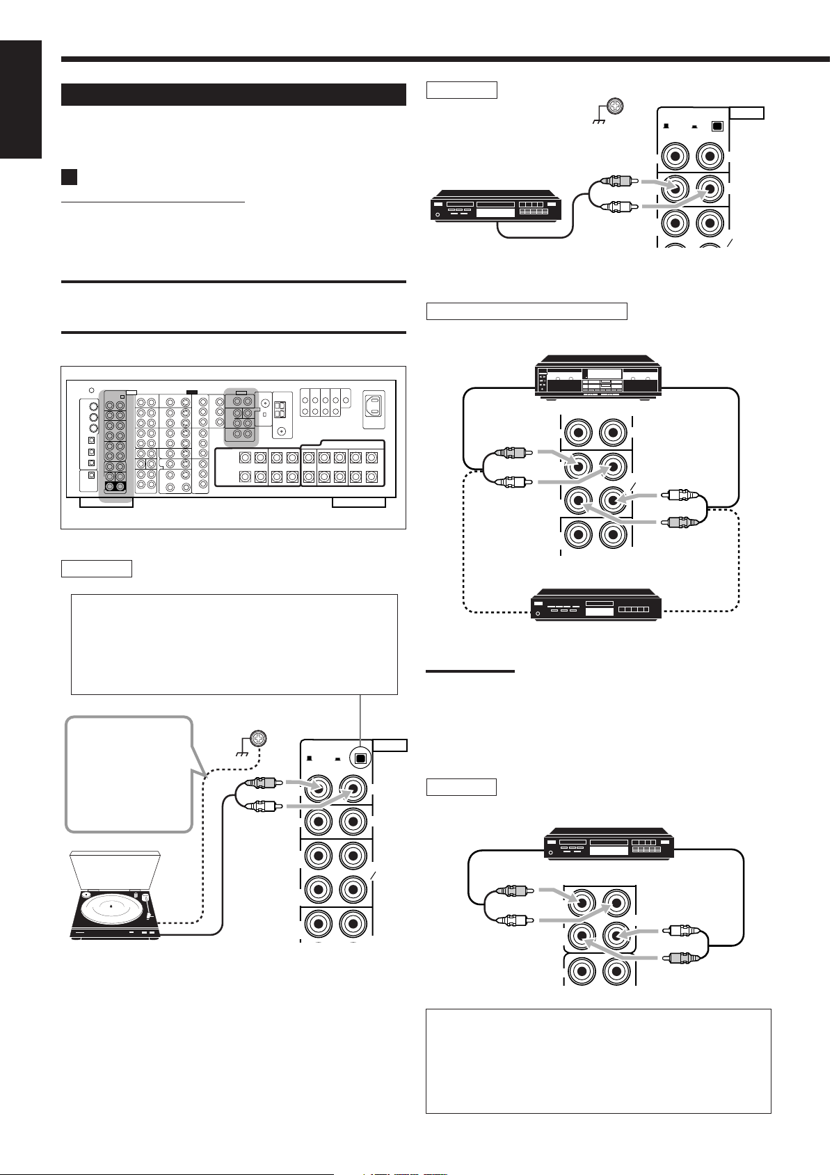
Analog Connections
Audio component connections
Use the cables with RCA pin plugs (not supplied).
• Connect the white plug to the audio left jack, and the red plug to
the audio right jack.
CAUTION:
If you connect a sound-enhancing device such as a graphic equalizer
between the source components and this receiver, the sound output
through this receiver may be distorted.
Rear view
Turntable
CD player
To audio output
Cassette deck or MD recorder
Cassette deck
To audio input
MD recorder
To audio output
Set the MM/MC selector correctly to match it to the
turntable connected.
• If an MM (moving-magnet) type cartridge is used by your
turntable, push out the selector (— MM).
• If an MC (moving-coil) type cartridge is used by your
turntable, push in the selector (_ MC).
If an earth cable is
provided for your
RIGHTMMLEFT
turntable, connect
the cable to the
screw marked (H)
on the rear panel.
Turntable
11
To audio output
IN
IN
OUT
(REC)
IN
(PLAY)
OUT
(REC)
To audio input
To audio output
Note:
You can connect either a cassette deck or an MD recorder to the
TAPE/MD jacks. When connecting an MD recorder to the TAPE/MD
jacks, change the source name to “MD,” which will be shown on the
display when selected as the source. See “Changing the Source
AUDIO
MC
PHONO
CD
TAPE
MD
Name” on page 27 for details.
CD recorder
To audio input
CD recorder
To audio output
If your audio components have a COMPU LINK or TEXT
COMPU LINK jack
• See page 61 for detailed information about the connection and
the COMPU LINK remote control system.
• See page 63 for detailed information about the connection and
the TEXT COMPU LINK remote control system.
Page 15
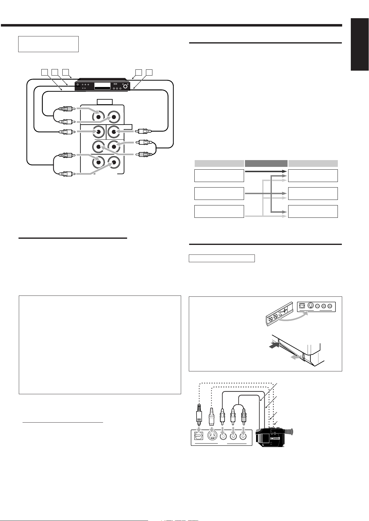
External 7.1-channel
EXT 7.1CH IN
R
L
RIGHT
LEFT
SURR
BACK
SUB
WOOFER
SURR
FRONT
CENTER
AUDIO
A B C
D E
R
L
R
L
R
L
Video Input Converted Video Output
Component
S-video
Video (composite)
Component
S-video
Video (composite)
S-VIDEODIGITAL
VIDEO L—AUDIO—R
VIDEO
R
L
S-VIDEODIGITAL
VIDEO L—AUDIO—R
VIDEO
output component
Decoder
(or DVD player)
Å To left/right front channel output
ı To LFE channel (subwoofer) output
Ç To left/right surround back channel output
Î To left/right surround channel output
‰ To center channel output
Note:
The ZIST circuit (see page 1) is incorporated for the EXT 7.1CH IN jacks
to clarify the audio signals independently from the video input circuit.
However, if the external component connected to the EXT 7.1CH IN jacks
and this receiver are not connected using video cords (composite, Svideo, or component), noise may happen to be generated when listening
to this external component.
In this case, connect the video output jacks on the external component
and unused video input jacks on this receiver.
IMPORTANT:
This receiver is equipped with the following video jacks—composite
video, S-video and component video jacks. You can use any of the
three to connect a video component
However, observe the following points when make connections:
• Composite video signals and S-video signals can be converted
into each other, and can be also converted into component
signals. So incoming signals of both types can be emitted through
all video output jacks. (If both signals are used, the unit
automatically gives priority to S-video signals.)
— Pictures may be distorted if the signals are converted. If this
happens, connect the playback source component and TV using
the cords of the same type.
• When the recording components and this unit are connected
using the video cords or S-video cords, playback components
and this unit need to be connected using the cords of the same
type.
• Component signals cannot be converted. So incoming signals of
this type can be emitted only through the component output jacks.
Notice: Pictures through the video components only
connected to the component input jacks on the rear of this unit
cannot be viewed in Zone 2.
Video camera
The VIDEO input terminals on the front panel are convenient when
connecting and disconnecting the component frequently.
• When you do not use the VIDEO input terminals, attach the front
terminal cover (supplied) to these jacks to protect them from dust.
English
How to view the pictures through an external component
connected to the EXT 7.1CH IN (audio input) jacks
The EXT 7.1CH IN jacks do not have any corresponding video input
jack on the rear. You have to use one of the following methods to
view the pictures through the external component.
• Connect the video output jack on the external component directly
to the TV, and select the connected input on the TV.
• Connect the video output jack on the external component to any
one of unused video input jacks on the rear, then...
1. Select that video input as the video source.
2. Select “EXT 7.1CH” as the audio source.
(See “Selecting different sources for picture and sound”
on page 24).
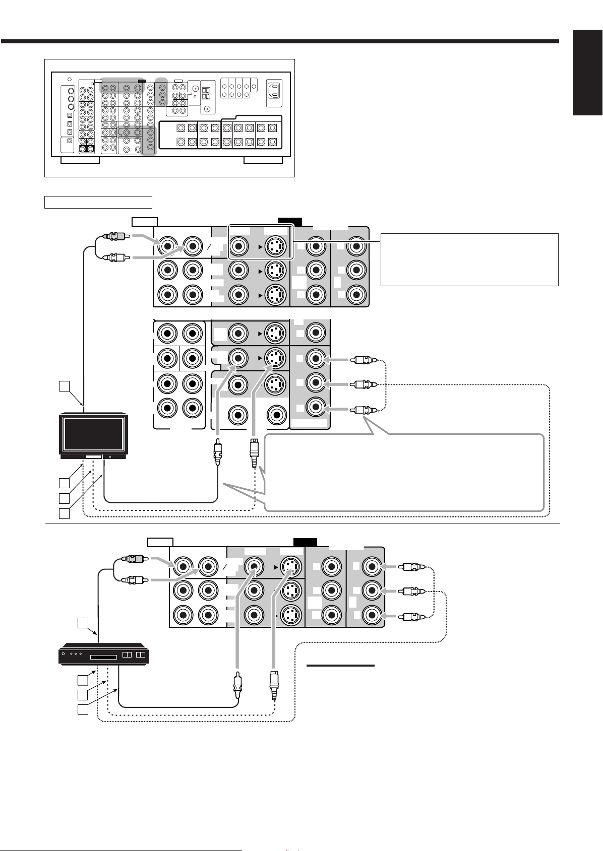
Video component connections
Use cables with RCA pin plugs (not supplied).
Connect the white plug to the audio left jack, the red plug to the
audio right jack, and the yellow plug to the video jack.
• If your video components have S-video (Y/C-separation) and/or
component video (Y, P
cable (not supplied) and/or component video cable (not supplied).
By using these jacks, you can get better picture quality—in the
order: Component video > S-video > Composite video.
B, PR) jacks, connect them using an S-video
• When attaching the front
terminal cover
• When removing the cover
To audio output
To composite video
output
To S-video output
To optical digital output
Video camera
When using the digital input terminal
Select the digital input mode correctly.
For details, see “Selecting the Analog or Digital Input Mode” on
page 25.
12
Page 16
English
VIDEO
RIGHT LEFT
DVD
IN
TV SOUND
DBS
IN
OUT
(REC)
IN
(PLAY)
VCR 1
VCR 2
S-VIDEO
VIDEO
Y
PB
PR
1 IN
(DVD)
Y
PB
PR
3 IN
Y
PB
PR
2
IN
FRONT
IN
(PLAY)
OUT
(REC)
COMPONENT
AUDIO
A B
C
D E F G
R
L
R
L
VIDEO
RIGHT LEFT
DVD
IN
TV SOUND
DBS
IN
OUT
(REC)
IN
(PLAY)
VCR 1
L
R
VCR 2
S-VIDEO
VIDEO
Y
PB
PR
1 IN
(DVD)
Y
PB
PR
3 IN
Y
PB
PR
MONITOR OUT
Y
PB
PR
2
IN
PREOUT
SURR
BACK
SUB
WOOFER
SURR
FRONT
IN
(PLAY)
OUT
(REC)
COMPONENT
AUDIO
ZONE 2
CENTER
LR
MONITOR
OUT
PREOUT
MONITOR
OUT
CBA
D E F
R
L
R
L
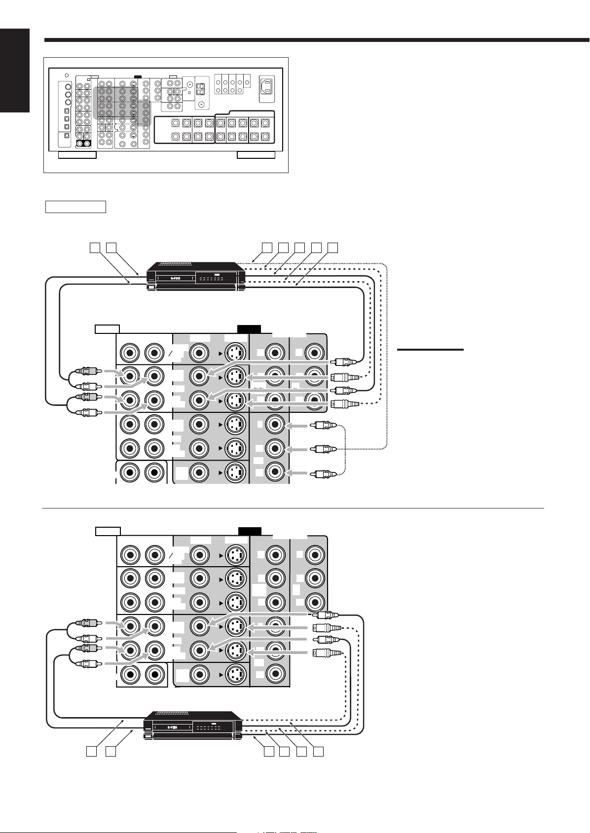
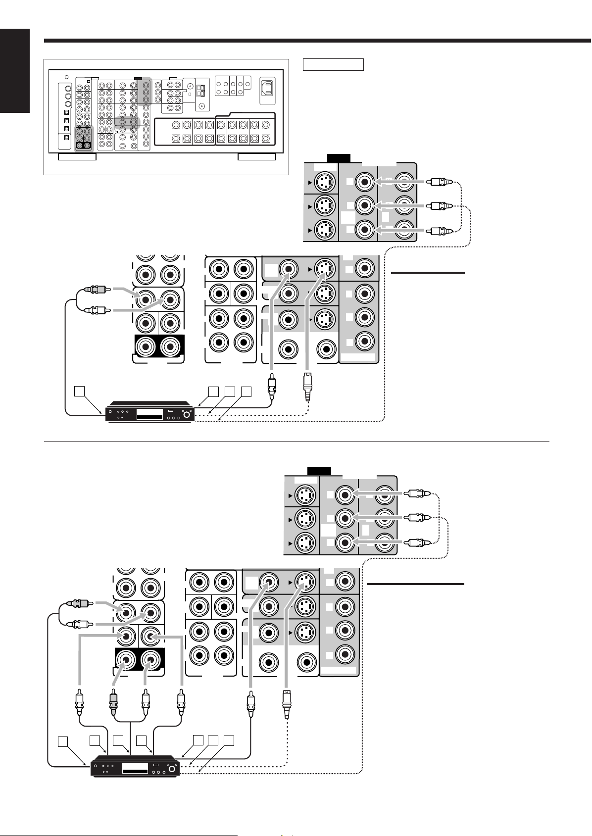
VCR(s)
Rear view
D-VHS/S-VHS/VHS
VCR
Å To audio input
ı To audio output
Ç To component video output
Î To S-video output
‰ To composite video output
Ï To S-video input
Ì To composite video input
Notes:
• If the VCR has component video output
jacks, you can connect it to either the
COMPONENT 1 IN (DVD), 2 IN, or 3 IN
jacks. When connecting the VCR to
either one of the component input jacks,
make the video input terminal setting
correctly. For details, see “
Video Input Terminals—VIDEO INPUT”
on page 43.
• To view the pictures through the VCR in
Zone 2, connect it to either S-video or
composite video input jacks.
p
Setting the
13
S-VHS/VHS VCR
Å To audio output
ı To audio input
Ç To composite video input
Î To S-video input
‰ To composite video output
Ï To S-video output
Page 17
TV and/or DBS tuner
DVD
IN
L
R
P
R
3 IN
Y
P
B
P
R
MONITOR OUT
PREOUT
SURR
BACK
SUB
WOOFER
SURR
FRONT
ZONE 2
CENTER
LR
MONITOR
OUT
PREOUT
MONITOR
OUT
VIDEO
RIGHT LEFT
TV SOUND
DBS
IN
OUT
(REC)
IN
(PLAY)
VCR 1
S-VIDEO
VIDEO
Y
P
B
P
R
1 IN
(DVD)
Y
P
B
P
R
2
IN
COMPONENT
AUDIO
A
B
C
D
R
L
VIDEO
RIGHT LEFT
TV SOUND
DBS
IN
OUT
(REC)
IN
(PLAY)
VCR 1
S-VIDEO
VIDEO
Y
P
B
P
R
1 IN
(DVD)
Y
P
B
P
R
2
IN
COMPONENT
AUDIO
DBS
A
B
C
D
R
L
English
Rear view
When connecting the TV to the AUDIO
jacks (TV SOUND/DBS IN), DO NOT
connect the TV’s video output to these
video input jacks.
Å To audio output
ı To component video input
Ç To S-video input
Î To composite video input
TV
Connect the TV to appropriate MONITOR OUT jacks to view the
playback picture from the connected video components.
• Using the component cords allows you to view the playback picture
from any other connected video components without using S-video or
composite video connections.
DBS tuner
Å To audio output
ı To component video output
Ç To S-video output
Î To composite video output
Notes:
• When connecting the DBS tuner to the TV SOUND/DBS IN jacks,
change the source name to “DBS,” which will be shown on the
display when selected as the source. See “Changing the Source
Name” on page 27 for details.
• If the DBS tuner has component video output jacks, you can connect
it to either the COMPONENT 1 IN (DVD), 2 IN, or 3 IN jacks. When
connecting the DBS tuner to either one of the component input
jacks, make the video input terminal setting correctly. For details, see
“
p
Setting the Video Input Terminals—VIDEO INPUT” on page 43.
• To view the pictures through the DBS tuner in Zone 2, connect it to
either S-video or composite video input jacks.
14
Page 18
English
VIDEO
S-VIDEO
Y
PB
PR
1 IN
(DVD)
Y
PB
PR
2
IN
COMPONENT
CDR
(REC)
FRONT
CENTER
L
R
IN
(PLAY)
SUB
WOOFER
DVD
IN
L
R
PR
3 IN
Y
PB
PR
MONITOR OUT
PREOUT
SURR
BACK
SUB
WOOFER
SURR
FRONT
ZONE 2
SURR
(REAR)
CENTER
LR
MONITOR
OUT
PREOUT
MONITOR
OUT
DVD IN
C D
F
G
E
DVD
B
A
R
L
R
L
VIDEO
S-VIDEO
Y
P
B
P
R
1 IN
(DVD)
Y
P
B
P
R
2
IN
COMPONENT
CDR
(REC)
FRONT
CENTER
L
R
IN
(PLAY)
SUB
WOOFER
DVD
IN
L
R
P
R
3 IN
Y
P
B
P
R
MONITOR OUT
PREOUT
SURR
BACK
SUB
WOOFER
SURR
FRONT
ZONE 2
SURR
(REAR)
CENTER
LR
MONITOR
OUT
PREOUT
MONITOR
OUT
DVD IN
DVD
A
B
C D
R
L
Å To front left/right channel audio output (or to audio-
ı To composite video output
Ç To S-video output
Î To component video output
Rear view
mixed output if necessary)
DVD player
DVD player
• When you connect the DVD player with stereo output jacks:
Notes:
• If the DVD player has component video
output jacks, you can connect it to either
the COMPONENT 1 IN (DVD), 2 IN, or 3
IN jacks. When connecting the DVD player
to either one of the component input jacks,
make video input terminal setting correctly.
For details, see “
Input Terminals—VIDEO INPUT” on page
43.
• To view the pictures through the DVD
player in Zone 2, connect it to either Svideo or composite video input jacks.
p
Setting the Video
• When you connect the DVD player with its analog discrete
output (5.1-channel reproduction) jacks:
Å To left/right front channel audio output
ı To subwoofer (LFE) output
Ç To left/right surround channel audio output
Î To center channel audio output
‰ To composite video output
Ï To S-video output
Ì To component video output
DVD player
15
Notes:
• If the DVD player has component video output
jacks, you can connect it to either the
COMPONENT 1 IN (DVD), 2 IN, or 3 IN jacks.
When connecting the DVD player to either one of
the component input jacks, make video input
terminal setting correctly. For details, see “
p
Setting the Video Input Terminals—VIDEO
INPUT” on page 43.
• To view the pictures through the DVD player in
Zone 2, connect it to either S-video or composite
video input jacks.
Page 19
Digital Connections
DIGITAL IN
1 (DVD)
2 (CD)
3 (TV
/DBS)
4 (CDR)
5 (MD)
6 (VCR 1)
PCM
/ DOLBY DIGITAL
/ DTS
DIGITAL OUT
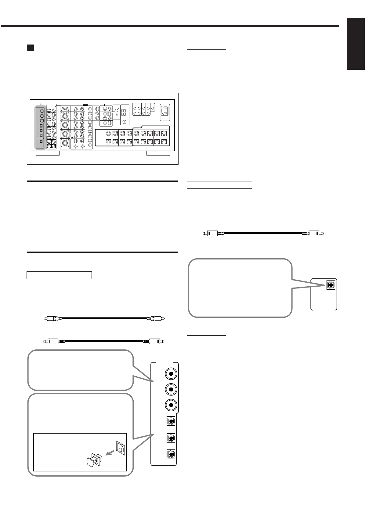
This receiver is equipped with six DIGITAL IN terminals—three
digital coaxial terminals and three digital optical terminals—and one
DIGITAL OUT (optical) terminal on the rear.
• Another digital optical input terminal is located on the front panel
(see page 12).
Rear view
IMPORTANT:
• When connecting the DVD player, digital TV broadcast tuner, digital
VCR, or DBS tuner using the digital terminals, you also need to
connect it to the video terminal on the rear. Without connecting it to
the video terminal, you cannot view any playback picture.
• After connecting the components using the DIGITAL IN terminals,
set the following correctly if necessary:
– Set the digital input (DIGITAL IN) terminal setting correctly. For
details, see “9 Setting the Digital Input/Output Terminals—
DIGITAL IN/OUT” on page 42.
– Select the digital input mode correctly. For details, see “Selecting
the Analog or Digital Input Mode” on page 25.
Notes:
• When shipped from the factory, the DIGITAL IN terminals have
been set for use with the following components:
– 1 (coaxial) : For DVD player
– 2 (coaxial) : For CD player
– 3 (coaxial) : For digital TV broadcast tuner
– 4 (optical) : For CD recorder
– 5 (optical) : For MD recorder
– 6 (optical) : For VCR 1 (VCR connected to the VCR 1 jacks)
• When you want to operate the CD player, CD recorder, or MD
recorder using the COMPU LINK or TEXT COMPU LINK remote
control system, connect the target component also as described in
“Analog Connections” (see page 11).
• When you want to operate the VCR, TV or DVD player using the AV
COMPU LINK remote control system, connect the target
component also as described in “Analog Connections” (see pages
13 to 15).
• To use the digital source components for Zone 2, connect them
using analog connection methods as well.
Digital output terminal
You can connect any digital component which have an optical
digital input terminal.
Digital optical cable (not supplied)
between digital optical terminals
English
Digital input terminals
You can connect any digital components having a coaxial or optical
digital output terminal.
Digital coaxial cable (not supplied)
between digital coaxial terminals
Digital optical cable (not supplied)
between digital optical terminals
When the component has a digital
coaxial output terminal, connect it to the
1 (DVD), 2 (CD), or 3 (TV/DBS) terminal,
using a digital coaxial cable (not
supplied).
When the component has a digital
optical output terminal, connect it to the
4 (CDR), 5 (MD), or 6 (VCR 1) terminal,
using a digital optical cable (not
supplied).
Before connecting a digital
optical cable, unplug the
protective plug.
When digital recording equipment
such as an MD recorder and a CD
recorder has a digital optical input
terminal, connecting it to the
DIGITAL OUT terminal enables you
to perform digital-to-digital
recording.
Note:
The format of the digital signals transmitted through the DIGITAL OUT
terminal can be determined using the Setup Menu.
For details, see “ 9 Setting the Digital Input/Output Terminals—
DIGITAL IN/OUT” on pages 42 and 43.
16
Page 20
1
2
Using the RF Rod Antenna and IR Signal
ANTENNA
RF REMOTE
BAND1
BAND2
BAND1
BAND2
ANTENNA
RF REMOTE
BAND1
BAND2
ANTENNA
RF REMOTE
Transmitter
English
The combination of the RF rod antenna and the IR signal transmitter
allows you to use the multi-room function more conveniently.
The remote control supplied for this receiver can transmit both RF
signal and IR signal at the same time. This receiver catches the RF
signals emitted from the remote control, and converts them into IR
signals, then transmits the converted signals to the remote sensor on
the other components through the IR signal transmitter.
This means that you can control not only this receiver but also other
components from Zone 2.
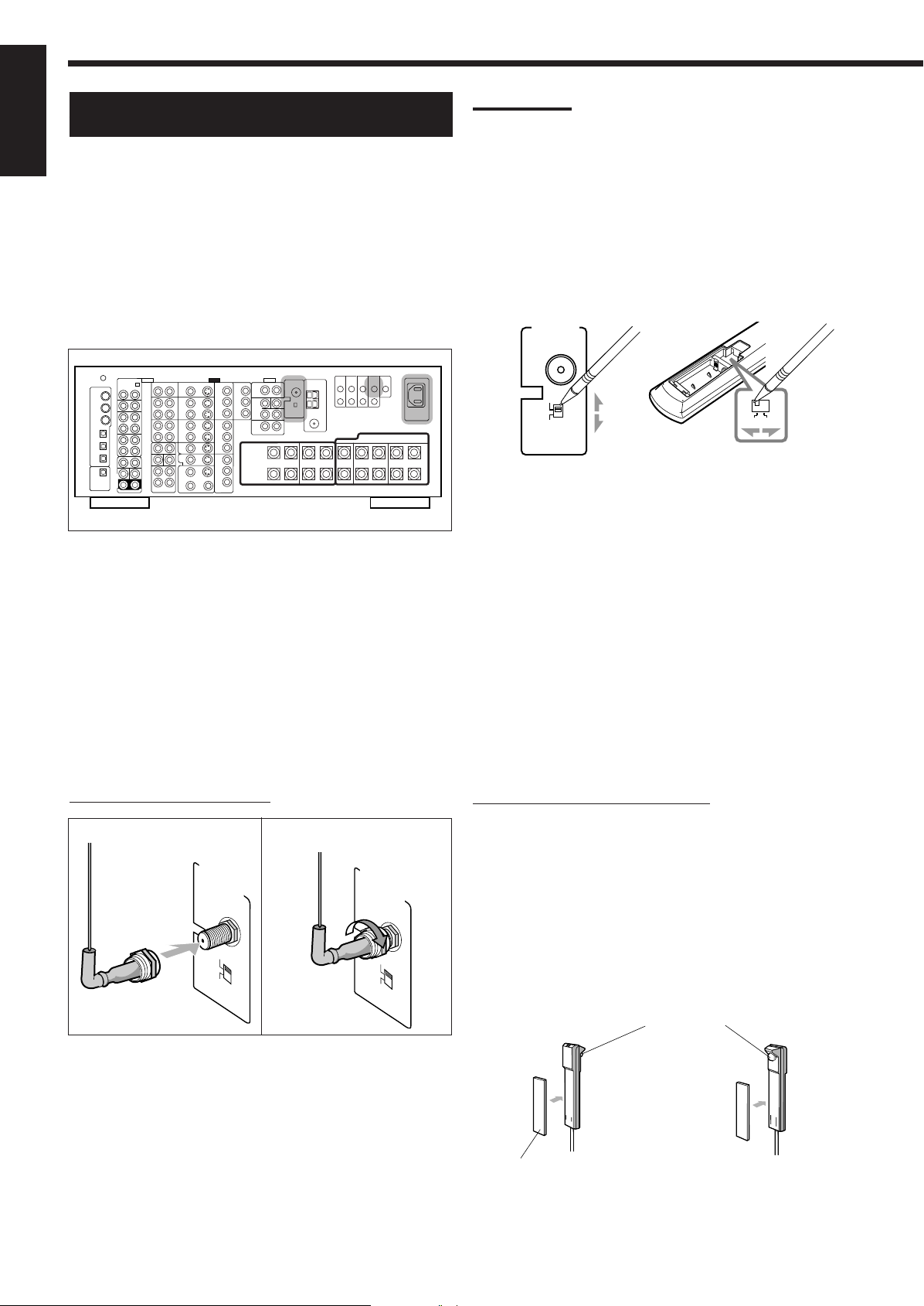
Setting Up the RF Rod Antenna
Notes:
• The signal-reachable distance may differ depending on the
operating conditions and circumstances. To improve transmitting
conditions, change the distance to the receiver and the direction to
transmit while operating the remote control.
• To avoid a failure in the reception from the remote control, keep the
connecting cables and the IR signal transmitter’s cable away from
the RF rod antenna.
• If your neighbour uses the same or similar RF remote control
system, the receiver may happen to receive the RF signals sent
from such an RF remote control system, which could cause your
receiver to be operated unintentionally. If this happens, set the
BAND 1/2 selectors (both on the rear and on the remote control) to
another band (either BAND 1 or BAND 2).
Rear view
The remote control supplied for this receiver can transmit both RF
(Radio Frequency) signals as well as IR (infrared) signals. The RF
rod antenna can receive the RF signals emitted from the remote
control. So, with the RF rod antenna connected, you can operate the
receiver at a distance of up to 15 m (50 feet) using RF signals sent
from this receiver (more than twice as far as when using IR signals).
Moreover, RF signals can go through walls and other objects in the
house so you need not aim at the receiver directly.
However, if the antenna cannot receive signals stably, you cannot
operate the receiver correctly.
• Without the RF rod antenna connected, you can operate the
receiver with the remote control, aiming the remote control
directly at the remote sensor on the receiver.
To set up the RF rod antenna
1
2
On the main unit’s rear
If the problem still persists, stop using the RF rod antenna and the
remote control, and consult your JVC dealer or the nearest JVC
Service Center.
On remote control
(Inside the battery compartment)
Setting Up the IR Signal Transmitter
The IR signal transmitter can retransmit the IR signals.
It allows you to use the AV COMPU LINK system, and to operate
other manufacturers’ components without aiming the remote control
directly at the remote sensor on the target components. In addition,
the IR signal transmitter reduces the possibility of malfunction.
• The IR signal transmitter may not operate the target components
depending on the operating conditions and circumstances—
including the aiming angle and direction of the IR signal
transmitter at the remote sensors of the target components. If
this occurs, changing its aiming angle and direction at the
remote sensors may solve the problem.
To set up the IR signal transmitter
1. Find a place where you can attach the IR signal
transmitter.
• Place the transmitter where the signal can reach the remote
sensor of the target components in a direct line of sight.
• If the cord length of the IR signal transmitter is not long
enough, use an extension cord (not supplied).
1. Insert the RF rod antenna onto the RF REMOTE
ANTENNA terminal.
2. Rotate the fixing nut to attach the RF rod
antenna firmly.
17
2. Attach the double-sided adhesive tape (supplied)
to the IR signal transmitter.
IR signal transmitter
or
Double-sided
adhesive tape
Page 21
3. Connect the plug of the transmitter to the IR
30°
30°
15°
45°
COMPU
LINK-4
(SYNCHRO)
AV
COMPU
LINK-
TEXT
COMPU
LINK
IR
OUT
IR
IN
CTRL
OUT
+12V
10mA MAX
Less than 3 m (10 feet)
At an angle of
approx. 60°
LIGHT
AC
IN
OUT jack of the receiver and attach the
transmitter.
Target component(s)
Putting Batteries in the Remote Control
Before using the remote control, insert the two supplied batteries
first.
English
Signal-emitting angle of the transmitter
Horizontally: 60˚
Vertically: 60˚
Connecting the Power Cord
Before plugging the receiver into an AC outlet, make sure that all
connections have been made.
Connect one end of the power cord to the
the rear (1) and the other end into an AC outlet (2) .
1
2
AC IN socket on
1
2
3
LR6(AM3)
/L40(15A)
1. On the back of the remote control, remove the
battery cover.
2. Insert the batteries.
• Make sure to match the polarity: (+) to (+) and (–) to (–).
3. Replace the cover.
If the remote control cannot transmit signals or operate the receiver
correctly, replace the batteries. Use two LR6(AM3)/L40(15A) type
(alkaline) dry-cell batteries.
Notes:
• If you aim the remote control directly at the remote sensor on the
receiver, you can operate the receiver at a distance of up to 7 m
(23 feet).
• When replacing the batteries, finish changing them without delay;
otherwise, the stored signals are all erased (see pages 74 to 80).
When using the remote control in the dark
Press LIGHT.
The buttons on the remote control are backlit
while you are using the remote control.
If you do not press any button for about 5
seconds, the backlight will turn off.
Keep the power cord away from the connecting cables and the
antenna. The power cord may cause noise or screen interference.
Note:
The preset settings such as preset channels and sound adjustment
may be erased in a few days in the following cases:
– When you unplug the power cord.
– When a power failure occurs.
CAUTIONS:
• Do not touch the power cord with wet hands.
• Do not pull on the power cord to unplug the cord.
When unplugging the cord, always grasp the plug so as not to
damage the cord.
CAUTIONS:
Follow these precautions to avoid leaking or cracking cells:
• Place batteries in the remote control so they match the polarity:
(+) to (+) and (–) to (–).
• Use the correct type of batteries. Batteries that look similar may
differ in voltage.
• Always replace both batteries at the same time.
• Do not expose batteries to heat or flame.
18
Page 22
Multi-Room Operations
RIGHT
LEFT
+
–
CAUTION :
SPEAKER
IMPEDANCE
FRONT 1 SPEAKERS
FRONT 2 /
ZONE 2 SPEAKERS
RIGHT
LEFT
CENTER
SPEAKER
816
FRONT 1 AND 2
/ ZONE 2:
416
FRONT 1 OR 2:
P
B
P
R
MONITOR OUT
ZONE 2
LR
PREOUT
MONITOR
OUT
R
L
R
L
Before operating this receiver any further, be familiar with this multi-room function.
This function enables you to listen to different sources in two different places (we call these two places “Zone 1 (main
room)” and “Zone 2 (sub-room)”) by using this receiver.
English
This section explains only the required speaker connections, the concept, and basic operations of the multi-room
function. For more detailed operations, see the respective pages in this manual.
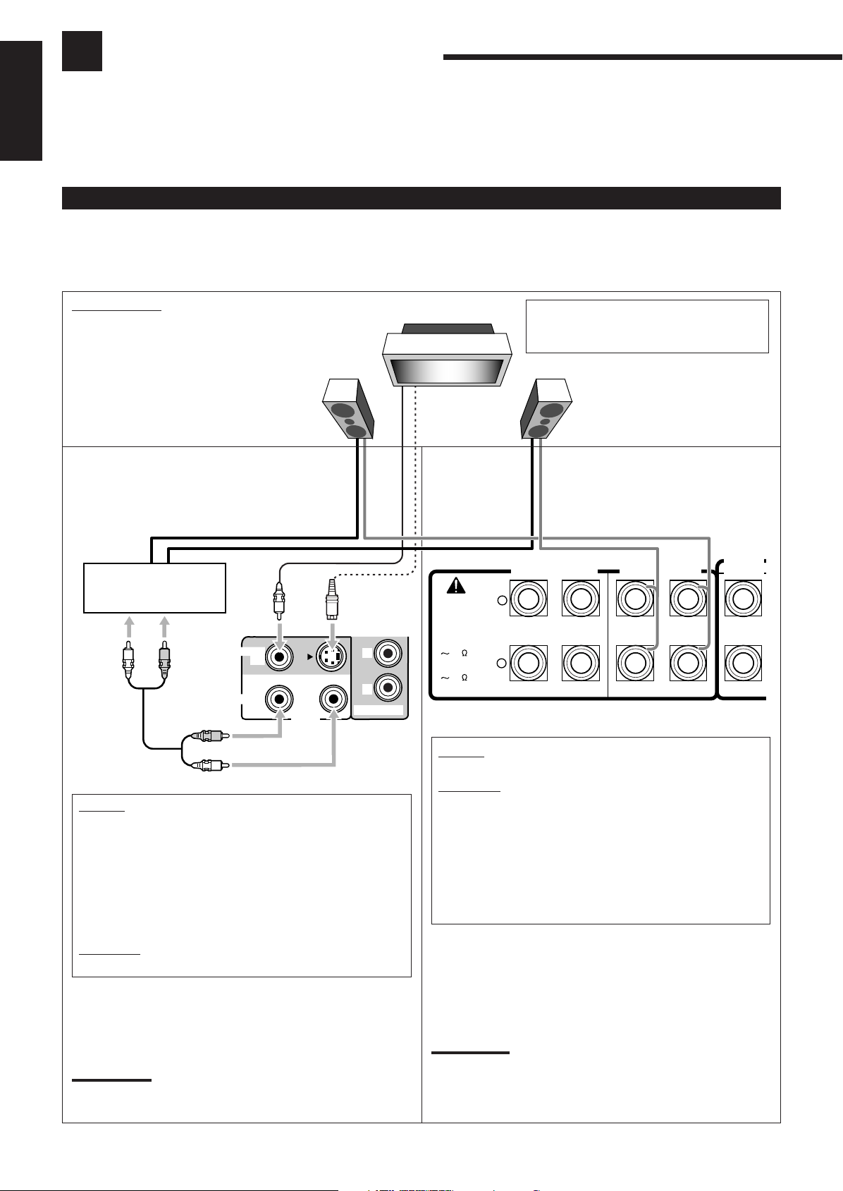
Required Connections for Zone 2
1. Connect a TV to the ZONE 2 MONITOR OUT jack (either composite video or S-video jack).
2. Connect front speakers by using one of the methods described below (either Connection Å or Connection ı).
Zone 2 Layout
Left front speaker
Connection Å
Connect the input jacks of another amplifier to the
ZONE 2 PREOUT jacks on the rear, using a cable
with RCA pin plugs (not supplied).
Power amplifier
TV
Connection ı
To use the Zone 2 TV
Turn on and select the correct input for this
receiver.
Right front speaker
Merits:
• This connection DOES allow you to always use the
Surround/THX/DSP mode using the center, surround, and
surround back speakers (see pages 51 and 58) and to select
“EXT 7.1CH” (see page 60) for the Zone 1 source.
• The output level through the ZONE 2 PREOUT jacks can
either be fixed or variable by setting it on the Setup Menu.
(See “w Setting the Zone 2/Speakers 2 Usage—ZONE 2/
SPEAKER 2” on page 43 for more details.)
Demerits:
• This connection DOES require another amplifier.
To use the Zone 2 front speakers
Turn on and operate the other amplifier connected to the ZONE 2
PREOUT jacks correctly.
Note:
Usage of long audio cables/long speaker signal cables will
deteriorate the signals and degrade the sound quality.
19
Merits:
• This connection DOES NOT require a power amplifier.
Demerits:
• When the Zone 2 speakers are activated, this connection
DOES NOT allow you to use the Surround/THX/DSP modes
using the surround back speakers (see pages 51 and 58) and
to select “EXT 7.1CH” (see page 60) for the Zone 1 source.
• When the Surround/THX/DSP modes using the surround
back speakers or when “EXT 7.1CH” is selected for Zone 1,
this connection DOES NOT allow you to use the Zone 2
speakers.
To use the Zone 2 front speakers connected to the FRONT 2/
ZONE 2 SPEAKERS terminals
See “w Setting the Zone 2/Speakers 2 Usage—ZONE 2/
SPEAKER 2” on page 43, and “Activating the Zone 2 Front
Speakers” on page 32.
Note:
Usage of long speaker signal cables will deteriorate the signals and
degrade the sound quality.
Page 23
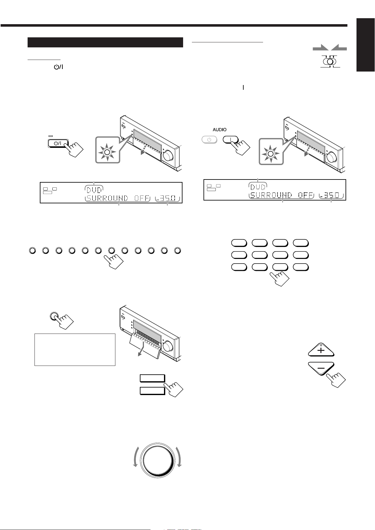
Basic Operating Procedure for Zone 1
DOOR
DOWN
SPEAKERS 1
SPEAKERS 2
/ ZONE 2
ZONE 2
TRANSMITLEARN
ZONE 1
L
ANALOG
SPEAKERS
VOLUME
1
SUBWFR
R
dB
dB
STANDBY/ON
STANDBY
DVD DVD MULTI VCR 1 VCR 2 TV/DBS CDVIDEO PHONO TAPE/MD CDR FM/AM EXT 7.1CH
MASTER VOLUME
ZONE 1
ON/OFF
STANDBY
ON
L
ANALOG
SPEAKERS
VOLUME
1
SUBWFR
R
dB
dB
ZONE 1
ON/OFF
DVD
DVD MULTI
CD
CDR
PHONO
TAPE/MD
EXT 7.1CH
VCR 1 VCR 2
FM/AMVIDEOTV/DBS
VOLUME
On the unit:
1. Press (STANDBY/ON).
The STANDBY lamp goes off, and the ZONE 1 ON/OFF lamp
lights up.
The front door moves down so that the source selecting buttons
appear, and the buttons and controls on the unit work for the
Zone 1 operations.
• For more details, see “Turning the Power On and Off
(Standby)” on page 22.
From the remote control:
1. Set ZONE 1/ZONE 2 (LEARN/
TRANSMIT) selector to “ZONE 1.”
Now the buttons and controls on the remote
control work for the Zone 1 operations.
2. Press AUDIO (ON).
The STANDBY lamp goes off, and the ZONE 1 ON/OFF lamp
on the unit lights up. The front door moves down.
• For more details, see “Turning the Power On and Off
(Standby)” on page 22.
English
The last Zone 1 source is activated.
The last Surround/THX/DSP
mode appears.
The volume
level appears.
2. Select and play a source.
The sound comes out of the Zone 1 speakers.
3. Press DOOR DOWN so that you can use the
other buttons inside the front door.
To close the front door, press
DOOR UP once or twice.
The front door moves up in two
steps.
The last Zone 1 source is activated.
The last Surround/THX/DSP
mode appears.
The volume
level appears.
3. Select and play a source.
The sound comes out of the Zone 1 front speakers.
• If no sound comes out of the front speakers, press SPEAKERS 1
and/or SPEAKERS 2 on the unit (inside the front door).
The selected front speaker indicator(s) light(s) up on the
display. For more details, see “Activating the Zone 1 Front
Speakers” on page 25.
4. Press VOLUME +/– to adjust the
volume level of the sound through
the Zone 1 speakers.
4. If no sound comes out of the front
speakers, press SPEAKERS 1
and/or SPEAKERS 2 which you
want to use.
The selected front speaker indicator(s) light(s) up on the display.
• For more details, see “Activating the Zone 1 Front Speakers”
on page 25.
5. Turn MASTER VOLUME to
adjust the volume level of the
sound through the Zone 1
speakers.
Down
Up
20
Page 24
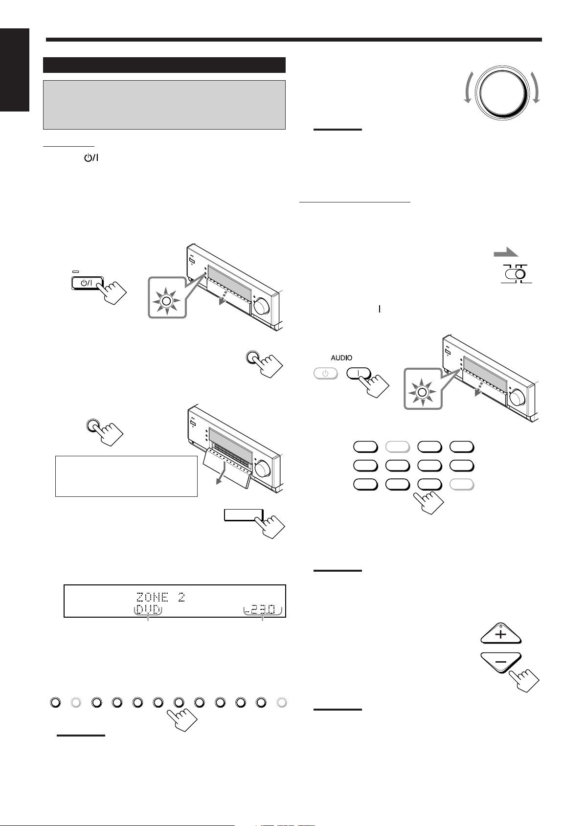
Basic Operating Procedure for Zone 2
ZONE 2
ON/OFF
ZONE 1
ON/OFF
MASTER VOLUME
STANDBY/ON
STANDBY
DOOR
DOWN
ZONE 2
CONTROL
SPEAKERS
VOLUME
ZONE 2
1
dB
dB
DVD DVD MULTI VCR 1 VCR 2 TV/DBS CDVIDEO PHONO TAPE/MD CDR FM/AM EXT 7.1CH
ZONE 2
TRANSMITLEARN
ZONE 1
DVD
DVD MULTI
CD
CDR
PHONO
TAPE/MD
EXT 7.1CH
VCR 1 VCR 2
FM/AMVIDEOTV/DBS
STANDBY
ON
ZONE 2
ON/OFF
VOLUME
English
The sources and functions available for the Zone 2
operations are limited.
For more details on the Zone 2 operations, see “Zone 2 (Subroom) Operations” on pages 29 to 32.
On the unit:
1. Press (STANDBY/ON).
The STANDBY lamp goes off, and the ZONE 1 ON/OFF lamp
lights up.
The front door moves down so that the source selecting buttons
appear, and the buttons and controls on the unit work for the
Zone 1 operations.
• For more details, see “Turning the Power On and Off (Standby)
and Selecting the Zone 2 Operations” on page 29.
2. Press ZONE 2 ON/OFF so that the
ZONE 2 ON/OFF lamp lights up.
6. Turn MASTER VOLUME to
adjust the volume level of the
sound through the Zone 2 front
speakers.
Note:
When “ZONE2PREOUT” is set to “FIX” on the ZONE 2/
SPEAKERS 2 submenu (see page 43), the MASTER VOLUME
control will not work for adjusting the volume level of the sound
through the ZONE2 PREOUT jacks.
From the remote control:
When operating the receiver using the remote control, the
display on the unit always shows the Zone 1 source information
though you are operating it for the Zone 2 source.
Down Up
1. Set ZONE 1/ZONE 2 (LEARN/
TRANSMIT) selector to “ZONE 2.”
Now the buttons and controls on the remote
control work for the Zone 2 operations.
2. Press AUDIO (ON).
The STANDBY lamp on the unit goes off, and the ZONE 2 ON/
OFF lamp on the unit lights up.
3. Press DOOR DOWN so that you can
use the other buttons inside the front door.
To close the front door, press
DOOR UP once or twice.
The front door moves up in two steps.
4. Press ZONE 2 CONTROL so that
“ZONE 2” and the previously
selected Zone 2 source name
appear on the display.
Now the buttons and controls on the unit work for the Zone 2
operations.
The last Zone 2 source appears.
The Zone 2 volume
level appears.
5. Select and play a source.
The sound comes out of the Zone 2 front speakers.
• If no sound comes out of the Zone 2 front speakers, see
page 32.
3. Select and play a source.
The sound comes out of the Zone 2 front speakers.
• If no sound comes out of the Zone 2 front speakers, see
page 32.
Notes:
• You cannot select “DVD MULTI” and “EXT 7.1CH” for Zone 2.
• When “TV” has been assigned as the source to the TV/DBS
button, it does not work. To change the source name, see
“Changing the Source Name” on page 27.
4. Press VOLUME +/– to adjust the
volume level of the sound through
the Zone 2 front speakers.
Notes:
• You cannot select “DVD MULTI” and “EXT 7.1CH” for Zone 2.
• When “TV” has been assigned as the source to the TV/DBS
button, it does not work. To change the source name, see
“Changing the Source Name” on page 27.
21
Note:
When “ZONE2PREOUT” is set to “FIX” on the ZONE 2/
SPEAKERS 2 submenu (see page 43), the VOLUME +/– control
will not work for adjusting the volume level of the sound through
the ZONE2 PREOUT jacks.
Page 25
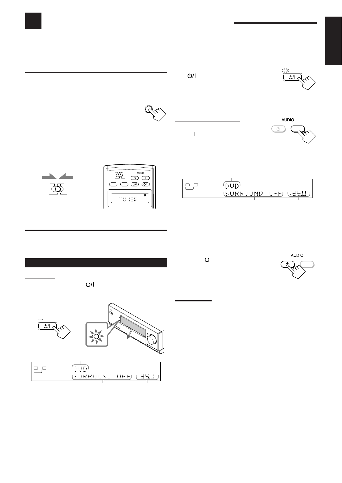
Zone 1 (Main Room) Operations
L
ANALOG
SPEAKERS
VOLUME
1
SUBWFR
R
dB
dB
STANDBY
ON
DOOR
DOWN
L
ANALOG
SPEAKERS
VOLUME
1
SUBWFR
R
dB
dB
ZONE 2
TRANSMITLEARN
ZONE 1
ON/OFF ON/OFF
STANDBY/ON STANDBY/ON
STANDBY
TV/CATV/DBS
VCR 1
ON
ZONE 2
TRANSMITLEARN
ZONE 1
ZONE 2
ZONE 1
ZONE 1
STANDBY/ON
STANDBY
ZONE 1
ON/OFF
STANDBY/ON
STANDBY
STANDBY
ON
This section explains only the operations commonly used when you play any sound source in Zone 1 (main room).
See pages 29 to 32 for the Zone 2 (sub-room) operations.
• Before performing Zone 1 operations, it is recommended to finish the basic settings on pages 35 to 44.
English
IMPORTANT:
Check the following before or while using the buttons and controls.
For Zone 1 operations:
The ZONE 1 ON/OFF lamp on the unit is lit.
• When using the unit:
– “ZONE 2” is not shown in the main display.
– Press DOOR DOWN to use the buttons inside the
front door.
To close the front door, press DOOR UP.
• When using the remote control:
– Set the ZONE 1/ZONE 2 (LEARN/TRANSMIT) selector to “ZONE 1.”
– Check the indication shown on the remote’s display when you
press a button—this indicates the remote control operation mode
together with multi-room operation mode (either ZONE 1 or
ZONE 2) for a while.
Ex. When you press FM/AM with ZONE 1/ZONE 2
(LEARN/TRANSMIT) selector set to “ZONE 1.”
To turn off the power (into standby mode),
press
(STANDBY/ON) again.
The STANDBY lamp lights up, and the front
door automatically closes. (The ZONE 1 ON/
OFF and/or ZONE 2 ON/OFF lamp goes off.)
• A small amount of power is consumed in standby mode. To turn
the power off completely, unplug the AC power cord.
From the remote control:
To turn on the power, press
AUDIO (ON).
The STANDBY lamp goes off, and the ZONE 1
ON/OFF lamp on the unit lights up.
The front door moves down (so that the source selecting buttons
appear).
The last Zone 1 source is activated.
The last Surround/THX/DSP
mode appears.
The volume
level appears.
The currently selected speakers 1 and/or 2 indicator(s) also light(s)
up on the display.
• If neither speakers 1 nor 2 indicator is lit on the display, see
“Activating the Zone 1 Front Speakers” on page 25.
Turning the Power On and Off (Standby)
On the unit:
To turn on the power, press (STANDBY/ON).
The STANDBY lamp goes off, and the ZONE 1 ON/OFF lamp
lights up. The front door moves down (so that the source selecting
buttons appear).
The last Zone 1 source is activated.
The last Surround/THX/DSP mode
appears.
The currently selected speakers 1 and/or 2 indicator(s) also light(s)
up on the display.
• If neither speakers 1 nor 2 indicator is lit on the display, see
“Activating the Zone 1 Front Speakers” on page 25.
The volume
level appears.
To turn off the power (into standby mode),
press AUDIO
(STANDBY).
The STANDBY lamp lights up, and the front
door automatically closes. (The ZONE 1 ON/
OFF and/or ZONE 2 ON/OFF lamp on the unit
goes off.)
Notes:
• Before you turn off the receiver in Zone 1, make sure that no one is
listening to any source in Zone 2 (the ZONE 2 ON/OFF lamp is lit
on the display) since the Zone 2 sound will also be turned off
unexpectedly.
• If you have turned off the receiver with the volume level set at more
than level “–35 dB,” the volume level will be automatically set at
level “–35 dB” next time you turn on the receiver.
When you turn on the TV connected to the TV SOUND/DBS
jacks on the rear
This receiver automatically turns on and selects “TV” as the Zone 1
source about 5 seconds after you turn on the TV. (If you change the
source name from “TV” to “DBS,” the receiver will not turn on
along with the TV. See “Changing the Source Name” on page 27.)
22
Page 26
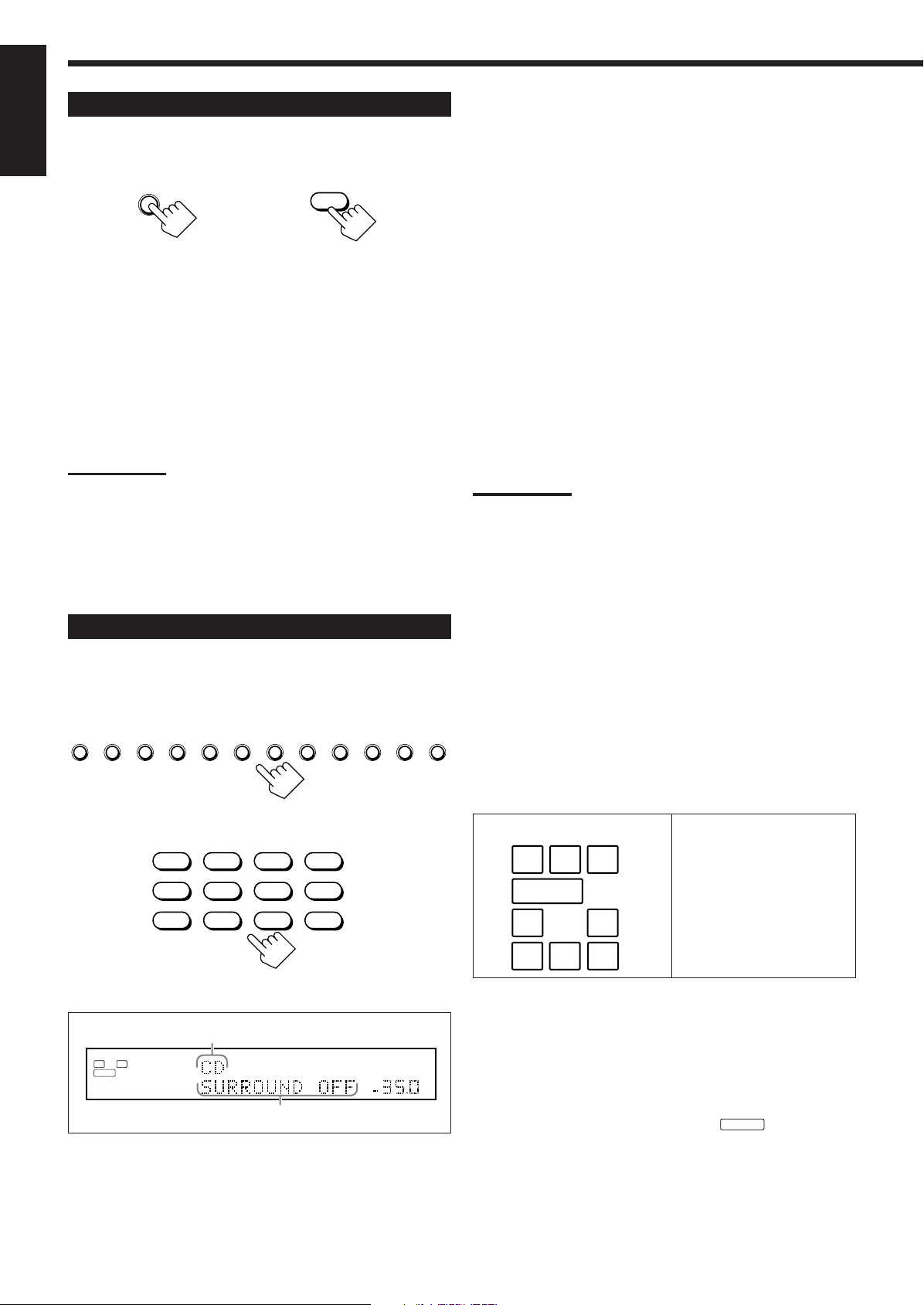
Canceling the Zone 1 Operations
SUBWFR
ZONE 1
ON/OFF
ON/OFF
ZONE 1
SUBWFR
LCR
LS RS
LFE
LCR
SLS
SB
RS
SB
DVD DVD MULTI VCR 1 VCR 2 TV/DBS CDVIDEO PHONO TAPE/MD CDR FM/AM EXT 7.1CH
DVD
DVD MULTI
CD
CDR
PHONO
TAPE/MD
EXT 7.1CH
VCR 1 VCR 2
FM/AMVIDEOTV/DBS
L
ANALOG
SPEAKERS
VOLUME
1
SUBWFR
R
dB
dB
English
To stop Zone 1 operations and sounds from the Zone 1 speakers,
press ZONE 1 ON/OFF so that the ZONE 1 ON/OFF lamp goes off.
On the unit
From the remote control
The currently selected front speakers indicator(s) also go(es) off
from the display (no sound will be heard in Zone 1).
To use this receiver for Zone 1 operations again, press
ZONE 1 ON/OFF again (the ZONE 1 ON/OFF lamp lights up).
The front speakers indicator(s) previously selected light(s) up.
Now the buttons and controls on the unit work for Zone 1
operations.
Notes:
• If you have turned off Zone 1 with the volume level set at more than
level “–35 dB,” the volume level will be automatically set at level
“–35 dB” next time you turn on Zone 1.
• If “TURN ON ZONE1 OR ZONE2” appears on the display, press
ZONE 1 ON/OFF or ZONE 2 ON/OFF to listen to the sound in Zone
1 or in Zone 2; otherwise, the receiver will turn off after about 1
minute.
Selecting the Zone 1 Source to Play
Press one of the source selecting buttons.
• The selected source name and Surround/THX/DSP mode also
appear on the display.
DVD : Selects the DVD player.
DVD MULTI :
Selects the DVD player for viewing a digital video
disc using the analog discrete output mode (5.1channel reproduction).
To use the DVD MULTI playback mode, see page 60.
VCR 1 : Selects the video component connected to the VCR 1
IN jacks.
VCR 2 : Selects the video component connected to the VCR 2
IN jacks.
TV/DBS : Selects TV sound (or the DBS tuner).
VIDEO : Selects the video component connected to the VIDEO
jacks.
CD* : Selects the CD player.
PHONO* : Selects the turntable.
TAPE/MD
* : Selects the cassette deck (or the MD recorder).
CDR* : Selects the CD recorder.
FM/AM* : Selects the tuner.
Each time you press the button, the band alternates
between FM and AM.
EXT 7.1CH
: Selects the external component connected to the EXT
7.1CH IN jacks.
To use the EXT 7.1CH playback mode, see page 60.
Notes:
• When connecting an MD recorder (to the TAPE/MD IN jacks), and a
DBS tuner (to the TV SOUND/DBS IN jacks), change the source
names shown on the display. For details, see “Changing the Source
Name” on page 27.
• When you press one of the audio source selecting buttons on the
remote control marked with an asterisk (*), the receiver
automatically turns on. If you turn on the receiver with the ZONE 1/
ZONE 2 (LEARN/TRANSMIT) selector set to “ZONE 2,” press
ZONE 1 ON/OFF to activate Zone 1 operations.
– If you press one of the audio source selecting buttons on the
remote control with the ZONE 1/ZONE 2 (LEARN/TRANSMIT)
selector set to “ZONE 1” while the receiver is turned on but Zone
1 is turned off, Zone 1 is turned on with the audio source
selected.
On the unit
From the remote control
Selected source name
The current Surround/THX/DSP mode appears.
Speaker and signal indicators on the display
By checking the following indicators, you can easily confirm which
speakers you are activating and which signals are coming into this
receiver.
Speaker indicators
What speaker indicators light depends on the speaker setting
(for details, see “1 Setting the Speakers—SPEAKER
SETTING” on page 38).
• The frames of “L,” “C,” “R,” “LS,” “RS, ” and “SB” light up,
when the corresponding speakers are set to “LARGE” or
“SMALL” and when the speaker is required for the Surround/
THX/DSP mode currently selected.
• When “SUBWOOFER” is set to “YES,”
• All three frames on the row of “SB” are not used at the same time.
When “SURR BACK OUT” is set to “2SPK,” the left and the right
ones are used. When it is set to “1SPK,” the middle one is used.
Signal indicators
lights up.
23
Page 27
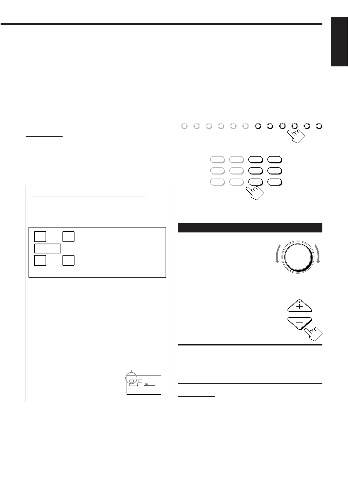
MASTER VOLUME
VOLUME
The signal indicators light up to show the incoming signals.
L
DGTL AUTO
DUAL
DIGITAL
SUBWFR
R
LFE
SUBWFR
LCR
LS RS
SB
DVD DVD MULTI VCR 1 VCR 2 TV/DBS CDVIDEO PHONO TAPE/MD CDR FM/AM EXT 7.1CH
DVD
DVD MULTI
CD
CDR
PHONO
TAPE/MD
EXT 7.1CH
VCR 1 VCR 2
FM/AMVIDEOTV/DBS
L : • When digital input is selected: Lights up when the left
channel signal comes in.
• When analog input is selected: Always lights up.
R : • When digital input is selected: Lights up when the right
channel signal comes in.
• When analog input is selected: Always lights up.
C : Lights up when the center channel signal comes in.
LFE : Lights up when the LFE channel signal comes in.
LS : Lights up when the left surround channel signal comes in.
RS : Lights up when the right surround channel signal comes in.
S : Lights up when the monaural surround channel signal
comes in.
SB : Lights up when the surround back channel signal comes in.
Notes:
• When “DVD MULTI” is selected as the source, “L,” “C,” “R,” “LFE,”
“LS” and “RS” light up.
• When “EXT 7.1CH” is selected as the source, “L,” “C,” “R,” “LFE,”
“LS,” “RS,” and “SB (left/right)” light up.
However, “SB” will not light if the THX mode or the DSP mode is
activated or if “SPEAKER 2” is set to “BI-AMP OUT” (see page 44).
How to use the speaker and signal indicators
To obtain the best performance of this receiver while using
the Surround/THX/DSP modes, check the speaker and signal
indicators on the display carefully and set the speakers correctly.
Selecting different sources for picture and
sound
While watching pictures from a video source (DVD player, VCR, or
DBS tuner), you can listen to sound of an audio source.
• Once you have selected a video source, pictures of the selected
source are sent to the TV until you select another video source.
Press one of the audio source selecting buttons—
PHONO, CD, TAPE/MD, CDR, FM/AM,
EXT 7.1CH—while viewing the picture from a video
component such as the VCR or DVD player, etc.
On the unit
From the remote control
English
Ex. No sound comes out of the
center speaker and surround
back speakers though center
channel and surround back
channel signals are coming
into this receiver.
About Dual Mono
Dual Mono can be easily understood when you think of the
bilingual broadcast or the MTS (Multi-channel TV Sound) used
for some TV programs (however, the Dual Mono format is not
identical with those analog formats).
This format is now adopted in Dolby Digital, DTS, and so on. It
allows two independent channels (called main channel and subchannel) to be recorded separately.
• When Dual Mono signals are detected, the
DUAL indicator lights up.
You can select either channel you want to
listen to (see page 42).
DUAL indicator
Adjusting the Zone 1 Volume
On the unit:
To increase the volume, turn MASTER
VOLUME clockwise.
To decrease the volume, turn it
counterclockwise.
Down
Up
• When you turn MASTER VOLUME rapidly,
the volume level also changes rapidly.
• When you turn MASTER VOLUME slowly, the volume level also
changes slowly.
From the remote control:
To increase the volume, press VOLUME +.
To decrease the volume, press VOLUME –.
CAUTIONS:
• Always set the volume to the minimum before starting any source. If
the volume is set at a high level, the sudden blast of sound energy
can permanently damage your hearing and/or ruin your speakers.
• Be careful not to turn up the volume too high when controlling the
receiver without listening to the playback sound. For example, when
adjusting the volume level in Zone 2 from Zone 1.
Notes:
• The volume level can be adjusted within the range of “– – – dB”
(minimum), “–71.0 dB” to “+18.0 dB” (maximum).
• If you set One Touch Operation to “ON” (see page 44), you do not
have to adjust the volume level each time you change the source. It
is automatically set to the stored level. (However, if you have turned
off the receiver with the volume level set at more than level “–35
dB,” the volume level will be automatically set at level “–35 dB” next
time you turn on the receiver.)
24
Page 28
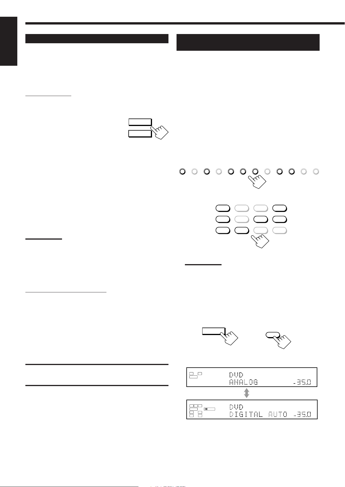
Activating the Zone 1 Front Speakers
SPEAKERS 1
SPEAKERS 2
/ ZONE 2
DVD DVD MULTI VCR 1 VCR 2 TV/DBS CDVIDEO PHONO TAPE/MD CDR FM/AM EXT 7.1CH
DVD
DVD MULTI
CD
CDR
PHONO
TAPE/MD
EXT 7.1CH
VCR 1 VCR 2
FM/AMVIDEOTV/DBS
INPUT MODE
/ INPUT ATT
dB
L
ANALOG
SPEAKERS
VOLUME
1
SUBWFR
R
dB
dB
L
DGTL AUTO
DIGITAL
SPEAKERS
VOLUME
1
SUBWFR
C R
LFE
RSLS
dB
INPUT
ANALOG/DIGITAL
English
When shipped from the factory, both pairs of the front speakers have
been set to be used in Zone 1.
• To connect the speakers to the FRONT 2/ZONE 2 SPEAKERS
terminals, set the speaker usage correctly. (See “w Setting the
Zone 2/Speakers 2 Usage—ZONE 2/SPEAKER 2” on page 43.)
On the unit ONLY:
When you have connected two pairs of front speakers and placed
them in Zone 1, you can select which to use.
To use the speakers connected to the FRONT
1 SPEAKERS terminals, press SPEAKERS 1
(inside the front door) so that the speakers 1
indicator lights up on the display. (Make sure
that the speakers 2 indicator is not lit on the display.)
To use the speakers connected to the FRONT 2/ZONE 2
SPEAKERS terminals, press SPEAKERS 2 (inside the front door)
so that the speakers 2 indicator lights up on the display. (Make sure
that the speakers 1 indicator is not lit on the display.)
To use both sets of the speakers, press SPEAKERS 1 and
SPEAKERS 2 so that the speakers 1 and 2 indicators light up on the
display.
To use neither set of the speakers, press SPEAKERS 1 and
SPEAKERS 2 so that the speakers 1 and 2 indicators disappear from
the display.
(“HEADPHONE” appears on the unit’s display.)
Selecting the Analog or Digital Input
Mode
When you have connected digital source components using the
digital terminals (see pages 12 and 16), you need to select the digital
input mode.
Before you start, remember...
• The digital input (DIGITAL IN) terminal setting should be
properly done (see “9 Setting the Digital Input/Output
Terminals—DIGITAL IN/OUT” on page 42).
• The digital input can be used for the Zone 1 sources. The analog
input is always selected as the Zone 2 source without respect to
this setting.
1. Press one of the source selecting buttons (DVD,
VCR 1, TV/DBS, VIDEO, CD, CDR, or TAPE/
MD*) for which you want to change the input
mode.
On the unit
Notes:
• Even if both pairs of the front speakers are activated, the speakers
connected to the FRONT 2/ZONE 2 SPEAKERS terminals are
deactivated in the following cases:
– If you select “DVD MULTI” or “EXT 7.1CH” as the source, or
– If you select one of the Surround/THX/DSP modes.
• The SPEAKERS 2 button will not work if “SPEAKER 2” is set to “BI-
AMP OUT” (see page 44).
Listening with headphones only:
Sounds through the front speakers and the subwoofer shut off when
connecting a pair of headphones to the PHONES jack.
(“HEADPHONE” appears on the unit’s display.)
You can enjoy the following sound effects through the headphones:
• If the Surround/THX mode is activated, you can enjoy surround
effect. (For details, see “3D HEADPHONE Mode” on page 57.)
• If a DSP mode is activated, you can enjoy the DSP effect. (For
details, see “HEADPHONE Mode” on page 58.)
CAUTION:
Be sure to turn down the volume before connecting or putting on
headphones, as high volume can damage both the headphones and
your hearing.
From the remote control
Note:
*
If “TAPE” has been assigned to the TAPE/MD button, it does not
work in this step.
To change the source name, see “Changing the Source Name”
on page 27.
2. Press INPUT MODE (or ANALOG/DIGITAL
INPUT) to change the input mode.
• Each time you press the button, the input mode changes as
follows:
On the unit
(inside the front door)
From the remote control
25
Ex. When the source is “DVD.”
Page 29
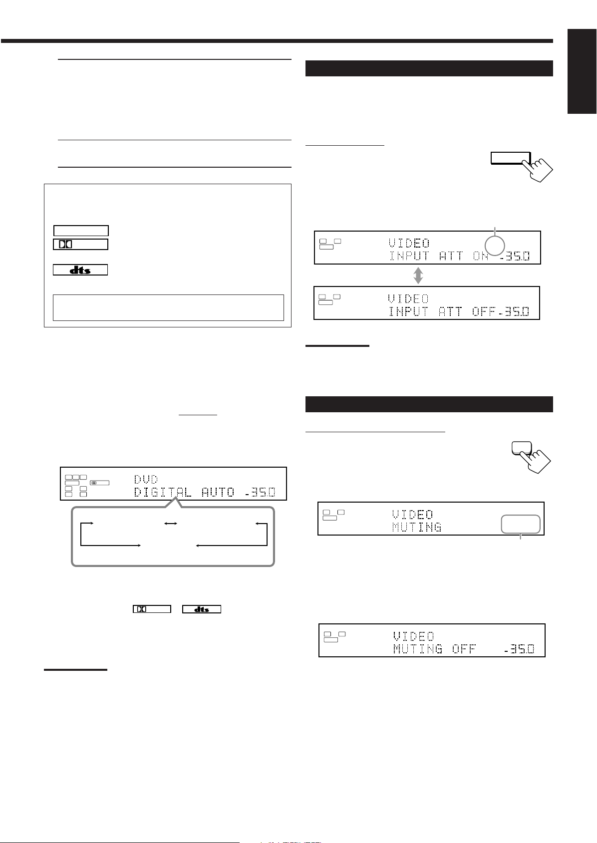
DIGITAL AUTO : Select this for the digital input mode.
LINEAR PCM
DIGITAL
DIGITAL
INPUT MODE
/ INPUT ATT
dB
L
ANALOG
SPEAKERS
VOLUME
1
SUBWFR
R
dB
L
ANALOG
SPEAKERS
VOLUME
INPUT
ATT
1
SUBWFR
R
dB
dB
L
DGTL AUTO
DIGITAL
SPEAKERS
VOLUME
1
SUBWFR
C R
LFE
RSLS
dB
DIGITAL AUTO
DGTL DOLBY D
(DOLBY DIGITAL)
DGTL
DTS
(DTS SURROUND)
MUTING
L
ANALOG
SPEAKERS
1
SUBWFR
R
dB
L
ANALOG
SPEAKERS
VOLUME
1
SUBWFR
R
The receiver automatically detects the
incoming signals.
The DGTL AUTO indicator lights up on
the display, and the digital signal format
indicators for the detected signals also
light up.
ANALOG : Select this for the analog input mode.
The ANALOG indicator lights up.
When selecting “DIGITAL AUTO,” the following indicators
indicate the digital signal format of the incoming signal.
: Lights up when Linear PCM signals come in.
: Lights up when Dolby Digital or Dolby Digital
EX signals come in.
: Lights up when DTS or DTS-ES signals come
in.
No indicator lights up when the receiver cannot recognize the
digital signal format of the incoming signals.
When playing software encoded with the Dolby Digital or DTS
Surround, the following symptoms may occur:
• Sound does not come out at the beginning of playback.
• Noise comes out while searching for or skipping chapters or
tracks.
In this case, press RIGHT (or LEFT)
on the unit to select “DGTL
DOLBY D” or “DGTL DTS” while “DIGITAL AUTO” still remains
on the display.
• Each time you press the button, the input mode changes as
follows:
Attenuating the Input Signal
When the input level of the playing source is too high, the sounds
will be distorted. If this happens, you need to attenuate the input
signal level to prevent sound distortion.
• You have to make this setting for analog each source.
On the unit ONLY:
Press and hold INPUT ATT (inside the
front door) so that the INPUT ATT
indicator lights up on the display.
• Each time you press and hold the button, the
input attenuator mode turns on (“INPUT ATT ON”) or off
(“INPUT ATT OFF”).
INPUT ATT indicator
Ex. When the source is “VIDEO.”
Notes:
• This effect is applied to only the Zone 1 analog sources.
• This function is not valid when Analog Direct is in use.
Muting the Zone 1 Sound
From the remote control ONLY:
Press MUTING to mute the sound
through all speakers in Zone 1 and
headphones connected.
“MUTING” appears on the display and the volume turns off (the
VOLUME level indicator goes off).
English
When “DOLBY DIGITAL” or “DTS SURROUND” is selected,
the DGTL AUTO indicator goes off, and the corresponding digital
signal format indicator (
display.
• If the incoming signal does not match the selected digital signal
Note:
When you turn off the power or select another source, “DOLBY
DIGITAL” and “DTS SURROUND” settings are canceled and the
digital input mode is automatically reset to “DIGITAL AUTO.”
or ) lights up on the
format, the frame of the selected indicator will flash.
Ex. When the source is “VIDEO.”
The VOLUME level
indicator goes off.
To restore the sound, press MUTING again so that “MUTING
OFF” appears on the display for a while.
• Turning MASTER VOLUME on the unit or pressing VOLUME
+/– on the remote control also restores the sound.
26
Page 30
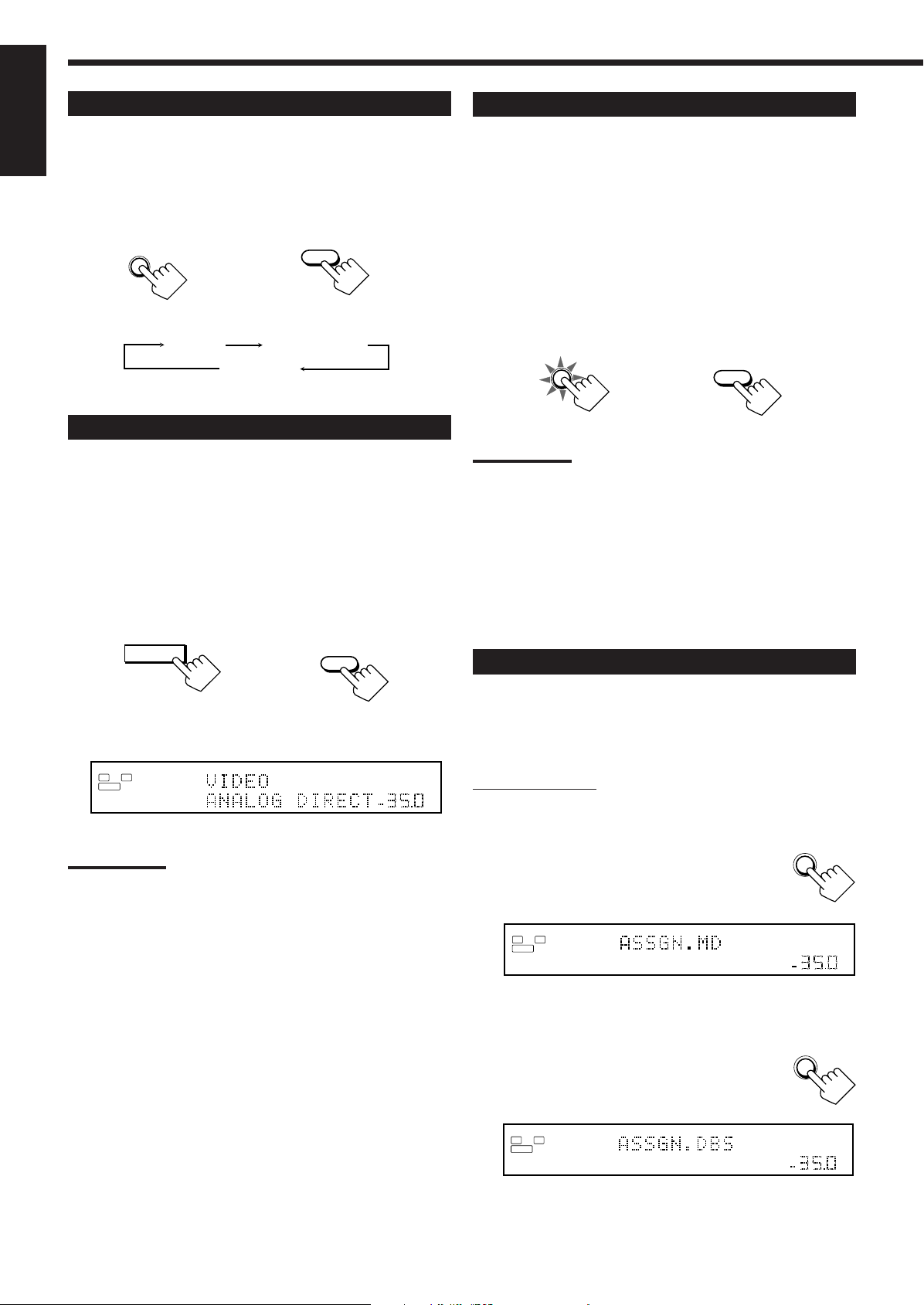
Changing the Display Brightness
DIMMER
Dimmer Much dimmer
Canceled
(Normal display)
dB
L
ANALOG
SPEAKERS
VOLUME
1
SUBWFR
R
ANALOG
DIRECT
ANALOG DIRECT
CC CONVERTER
CC CONVERTER
DIMMER
TV/DBS
TAPE/MD
L
ANALOG
SPEAKERS
VOLUME
1
SUBWFR
RdBL
ANALOG
SPEAKERS
VOLUME
1
SUBWFR
R
dB
English
You can dim the display.
Press DIMMER.
• Each time you press the button, the brightness level of the display
changes as follows:
From the remote controlOn the unit
Making Sounds Natural
JVC’s CC (Compensative Compression) Converter eliminates jitter
and ripples, achieving a drastic reduction in digital distortion by
processing the digital music data in 24 bit quantization and by
expanding the sampling frequency to 128 kHz (for fs 32 kHz)/
176.4 kHz (for fs 44.1 kHz signals)/192 kHz (for fs 48 kHz signals).
By using the CC Converter, you can obtain a natural sound field
from both digital and analog sources.
Press CC CONVERTER so that the CC
CONVERTER lamp lights up.
• Each time you press the button, CC Converter turns on and off (the
lamp goes off) alternately.
Turning Analog Direct On and Off
You can enjoy the sound quality closer to the original source by
skipping the sound adjustments such as Parametric Equalizer (see
page 48) and Midnight mode (see page 49). You can only adjust the
volume level while Analog Direct is in use.
• You have to make this setting for analog each source.
Press ANALOG DIRECT.
• Each time you press the button, Analog Direct turns on and off.
– When Analog Direct turns on, “ANALOG DIRECT” appears in
the main display.
On the unit
(inside the front door)
Ex. When the source is “VIDEO.”
Notes:
• This function is applied only to the Zone 1 analog sources.
• Activating one of the Surround/THX/DSP modes will cancel Analog
Direct automatically.
• If you turn on Analog Direct, the following settings are canceled
temporarily—Surround/THX/DSP modes (pages 51 and 58), Input
Attenuator (see page 26) and CC Converter, Parametric Equalizer
(page 48), and Midnight mode (page 49).
Turning off Analog Direct activates the above settings except the
speaker output level settings.
• If you turn off Analog Direct while listening to an analog source,
muting time* will be a little longer. (* The period during which no
sound comes out.)
From the remote control
On the unit
From the remote control
Notes:
• This function is applied only to the Zone 1 sources.
• You cannot use this function while Analog Direct or THX mode is in
use. If you turn on Analog Direct or THX mode while this function is
in use, this function will be canceled temporarily.
• This function does not work for the surround back channel when
the source is “EXT 7.1CH.”
• This function is also applied to the output signals through the
DIGITAL OUT terminal if the digital signals of fs 48 kHz or less
come in (except if the digital signals including surround back
signals come in with the surround back speakers activated).
Changing the Source Name
When you have connected an MD recorder to the TAPE/MD IN
jacks or the DBS tuner to the TV SOUND/DBS IN jacks on the rear
panel, change the source name which will be shown on the display
when you select the MD recorder or DBS tuner as the source.
On the unit ONLY:
When changing the source name from “TAPE” to
“MD”:
1. Press TAPE/MD.
2. Press and hold TAPE/MD until
“ASSGN. MD” appears on the display.
When changing the source name from “TV ” to
“DBS”:
1. Press TV/DBS.
27
2. Press and hold TV/DBS until “ASSGN.
DBS” appears on the display.
Page 31

To change the source name to “TAPE” or “TV,” repeat the same
SLEEP
2010 30 40 50 60 70 80 90
(Canceled)
0
L
ANALOG
SLEEP
SPEAKERS
VOLUME
1
SUBWFR
R
dB
procedure above—press and hold TAPE/MD to select “TAPE,” or
press and hold TV/DBS to select “TV” in step 2.
• While selecting “DBS” as the Zone 2 source, you cannot change
the source name to “TV.”
Notes:
• Once you change the source name, it is applied both for the Zone 1
and Zone 2 sources.
• Without changing the source name, you can still use the connected
components. However, there may be some inconvenience:
–“TAPE” or “TV” will appear on the display when you select the
MD recorder or DBS tuner.
– You cannot use the digital input (see page 25) for the MD
recorder.
– You cannot use the COMPU LINK or TEXT COMPU LINK remote
control system (see pages 61 and 63) to operate the MD
recorder.
Using the Sleep Timer
Recording a Source
For analog-to-analog recording
You can record any analog source through the receiver to—
• the cassette deck (or MD recorder) connected to the TAPE/
MD OUT jacks,
• the VCRs connected to the VCR 1 OUT and VCR 2 OUT
jacks, and
• the CD recorder connected to the CDR OUT jacks
— at the same time.
For digital-to-digital recording
You can record the currently selected digital input source
through the receiver to a digital recording device connected to
the DIGITAL OUT terminal.
Notes:
• Analog-to-digital and digital-to-analog recordings are not
possible.
• No sound adjustments can affect the recording.
English
Using the Sleep Timer, you can fall asleep to music and know the
receiver will turn off by itself rather than play all night.
• Sleep Timer works for the Zone 1 source only.
From the remote control ONLY:
Press SLEEP repeatedly.
The SLEEP indicator lights up on the display, and the
shut-off time changes as follows (in minutes):
SLEEP indicator
Ex. When the source is “VIDEO.”
When the shut-off time comes
The receiver turns off automatically.
• If the Zone 2 source is still playing (the ZONE 2 ON/OFF lamp is
lit) when the shut-off time comes, the receiver will not turn off,
and only the Zone 1 source will shut off.
To check or change the time remaining until the shut-off time
Press SLEEP once.
The remaining time until the shut-off time appears in minutes.
• To change the shut-off time, press SLEEP repeatedly.
To cancel the Sleep Timer
Press SLEEP repeatedly until “SLEEP 0min.” appears on the
display. (The SLEEP indicator goes off.)
• Turning off the power also cancels the Sleep Timer.
IMPORTANT:
• While recording, do not turn off the receiver or Zone 1 source;
otherwise, recording will stop.
• If the same source is selected both for Zone 1 and
Zone 2, operating the Zone 2 source will affect the recording.
Basic adjustment auto memory
This receiver memorizes sound settings for each Zone 1
source—
• when you turn on the power,
• when you change the source, and
• when you turn on One Touch Operation (see page 44).
When you change the Zone 1 source, the memorized settings for
the newly selected source are automatically recalled.
The following can be stored for each source:
• Analog/digital input mode (see page 25)
• Input Attenuator mode (see page 26)
• Analog Direct (see page 27)
• Parametric Equalizer setting (see page 48)
• Midnight mode (see page 49)
• Surround/THX mode (see page 51)
• DSP mode (see page 58)
Notes:
• If the source is FM or AM, you can assign a different setting for
each band.
• The memorized settings are not applied when a source is
selected for Zone 2.
• If you want to memorize the volume level together with the
above settings, set One Touch Operation to “ON” (see page
44).
28
Page 32

Zone 2 (Sub-room) Operations
STANDBY/ON
STANDBY
L
ANALOG
SPEAKERS
VOLUME
1
SUBWFR
R
dB
dB
ZONE 2
CONTROL
ZONE 2
ON/OFF
ZONE 1
ON/OFF
SPEAKERS
VOLUME
ZONE 2
1
dB
dB
DOOR
DOWN
ON/OFF ON/OFF
STANDBY/ON STANDBY/ON
STANDBY
TV/CATV/DBS
VCR 1
ON
ZONE 2
TRANSMITLEARN
ZONE 1
ZONE 2
ZONE 1
ZONE 2
ZONE 2
TRANSMITLEARN
ZONE 1
This section explains only the operations used when you play a sound source in Zone 2.
See pages 22 to 28 for the Zone 1 operations.
English
• Before performing the Zone 2 operations, it is recommended to finish the basic settings on pages 35 to 44.
IMPORTANT:
Check the following before or while using the buttons and controls.
For Zone 2 operations:
The ZONE 2 ON/OFF lamp on the unit is lit.
• When using the unit:
–“ZONE 2” is shown in the main display.
– Press DOOR DOWN to use the buttons inside the
front door.
To close the front door, press DOOR UP.
• When using the remote control:
When operating the receiver using the remote control, the
display on the unit always shows the Zone 1 source
information though you are operating it for the Zone 2
source.
– Set the ZONE 1/ZONE 2 (LEARN/TRANSMIT) selector to “ZONE 2.”
– Check the indication shown on the remote’s display when you
press a button—this indicates the remote control operation mode
together with multi-room operation mode (either ZONE 1 or
ZONE 2) for a while.
Turning the Power On and Off (Standby)
and Selecting the Zone 2 Operations
On the unit:
1. Press (STANDBY/ON).
The STANDBY lamp goes off, and the ZONE 1 ON/OFF lamp
lights up.
The front door moves down so that the source selecting buttons
appear.
• The unit is now activated only for Zone 1 operations.
The last Zone 1 source is activated.
The last Surround/THX/DSP
mode appears.
The volume
level appears.
Ex. When you press FM/AM with ZONE 1/ZONE 2
(LEARN/TRANSMIT) selector set to “ZONE 2.”
To use the Zone 2 TV (connected to the ZONE 2 MONITOR
OUT jack)
Turn on the TV and select the correct input for this receiver
manually.
For those who connect the Zone 2 front speakers to the
ZONE 2 PREOUT jacks through another amplifier (see page
19)
You have to determine how to adjust the volume level through the
Zone 2 front speakers. (See “w Setting the Zone 2/Speakers 2
Usage—ZONE 2/SPEAKER 2” on page 43 for more details.)
To use the Zone 2 front speakers
1 Turn on the other amplifier connected to the ZONE 2
PREOUT jacks.
2 Adjust the volume level through the Zone 2 front speakers
either on the other amplifier or on this receiver (depending on
the ZONE2PREOUT setting—see page 43).
The currently selected speakers 1 and/or 2 indicator(s) light(s)
up on the display.
2. Press ZONE 2 ON/OFF so that the
ZONE 2 ON/OFF lamp lights up.
• When connecting the Zone 2 front speakers to
the FRONT 2/ZONE 2 SPEAKERS
terminals, see also “w Setting the Zone 2/Speakers 2
Usage—ZONE 2/SPEAKER 2” on page 43, and “Activating
the Zone 2 Front Speakers” on page 32.
3. Press ZONE 2 CONTROL (inside
the front door) so that “ZONE 2”
and the previously selected Zone 2
source name appear on the display.
The last Zone 2
source appears.
Now the buttons and controls on the unit work for Zone 2
operations.
• Each time you press the button, the buttons and controls on the
unit are activated or deactivated for Zone 2 operations.
The Zone 2 volume
level appears.
29
Page 33

To turn off the power (into standby mode),
STANDBY/ON
STANDBY
ZONE 2
ON/OFF
SPEAKERS
VOLUME
ZONE 2
1
dB
dB
L
ANALOG
SPEAKERS
VOLUME
1
SUBWFR
R
dB
ZONE 2
ON/OFF
ZONE 2
CONTROL
SPEAKERS
VOLUME
ZONE 2
1
dB
dB
ON/OFF
ZONE 2
ZONE 2
TRANSMITLEARN
ZONE 1
ZONE 2
ON/OFF
STANDBY
ON
STANDBY
ON
press (STANDBY/ON) again.
The STANDBY lamp lights up, and the front
door automatically closes. (The ZONE 1 ON/
OFF and/or ZONE 2 ON/OFF lamp goes off.)
• A small amount of power is consumed in standby mode. To turn
the power off completely, unplug the AC power cord.
From the remote control:
1. Set ZONE 1/ZONE 2 (LEARN/
TRANSMIT) selector to “ZONE 2.”
Now the buttons and controls on the remote
control work for Zone 2 operations.
2. Press AUDIO (ON).
The STANDBY lamp on the unit goes off, and the ZONE 2 ON/
OFF lamp on the unit lights up.
• When connecting the Zone 2 front speakers to the FRONT 2/
ZONE 2 SPEAKERS terminal, see also “w Setting the Zone
2/Speakers 2 Usage—ZONE 2/SPEAKER 2” on page 43, and
“Activating the Zone 2 Front Speakers” on page 32.
Canceling the Zone 2 Operations
On the unit:
To stop Zone 2 operations and sounds through the
Zone 2 speakers, press ZONE 2 ON/OFF so that the
ZONE 2 ON/OFF lamp goes off.
No sound will be heard in Zone 2, and the display
changes to show the Zone 1 source.
To use this receiver for Zone 2 operations again
1. Press ZONE 2 ON/OFF again so that the
ZONE 2 ON/OFF lamp lights up.
2. Press ZONE 2 CONTROL (inside the front
door).
The name of the current source for Zone 2
appears on the display.
English
To turn off the power (into standby mode),
press AUDIO
(STANDBY).
The STANDBY lamp lights up, and the front
door automatically closes. (The ZONE 1 ON/
OFF and/or ZONE 2 ON/OFF lamp on the unit
goes off.)
Note:
If you have turned off the receiver with the volume level set at more
than level “–35 dB,” the volume level will be automatically set at level
“–35 dB” next time you turn on the receiver.
From the remote control:
To stop Zone 2 operations and sounds through the
Zone 2 speakers, press ZONE 2 ON/OFF so that the
ZONE 2 ON/OFF lamp on the unit goes off.
To use this receiver for Zone 2 operations
again, press ZONE 2 ON/OFF again.
Notes:
• If you have turned off Zone 2 with the volume level set at more than
level “–35 dB,” the volume level will be automatically set at level
“–35 dB” next time you turn on Zone 2.
• If “TURN ON ZONE1 OR ZONE2” appears on the display, press
ZONE 1 ON/OFF or ZONE 2 ON/OFF to listen to the sound in
Zone 1 or in Zone 2; otherwise, the receiver will turn off after about
1 minute.
30
Page 34

Selecting the Zone 2 Source to Play
DVD DVD MULTI VCR 1 VCR 2 TV/DBS CDVIDEO PHONO TAPE/MD CDR FM/AM EXT 7.1CH
DVD
DVD MULTI
CD
CDR
PHONO
TAPE/MD
EXT 7.1CH
VCR 1 VCR 2
FM/AMVIDEOTV/DBS
SPEAKERS
VOLUME
ZONE 2
1
dB
dB
MASTER VOLUME
VOLUME
DVD DVD MULTI VCR 1 VCR 2 TV/DBS CDVIDEO PHONO TAPE/MD CDR FM/AM EXT 7.1CH
DVD
DVD MULTI
CD
CDR
PHONO
TAPE/MD
EXT 7.1CH
VCR 1 VCR 2
FM/AMVIDEOTV/DBS
English
Press one of the source selecting buttons.
On the unit
Selecting different sources for picture and
sound
While watching pictures from a video source (DVD player, VCR, or
DBS tuner), you can listen to sound of an audio source.
• Once you have selected a video source, pictures of the selected
source are sent to the TV until you select another video source.
Press one of the audio source selecting buttons—
PHONO, CD, TAPE/MD, CDR, FM/AM—while
viewing the picture from a video component such as
the VCR or DVD player, etc.
Selected source name
The Zone 2 volume
level appears.
From the remote control
DVD : Selects the DVD player.
VCR 1 : Selects the video component connected to the
VCR 1 IN jacks.
VCR 2 : Selects the video component connected to the
VCR 2 IN jacks.
TV/DBS : Selects the DBS tuner.
• Does not work for selecting TV.
VIDEO : Selects the video component connected to the
VIDEO jacks.
CD* : Selects the CD player.
PHONO* : Selects the turntable.
TAPE/MD* : Selects the cassette deck (or the MD recorder).
CDR* : Selects the CD recorder.
FM/AM* : Selects the tuner.
Each time you press the button, the band alternates
between FM and AM.
On the unit
From the remote control
Adjusting the Zone 2 Volume
On the unit:
To increase the volume, turn MASTER
VOLUME clockwise.
To decrease the volume, turn it
counterclockwise.
• When you turn MASTER VOLUME rapidly,
the volume level also changes rapidly.
• When you turn MASTER VOLUME slowly,
the volume level also changes slowly.
From the remote control:
To increase the volume, press VOLUME +.
To decrease the volume, press VOLUME –.
Down
Up
Notes:
• When you press one of the audio source selecting buttons on the
remote control marked with an asterisk (*), the receiver
automatically turns on. If you turn on the receiver with ZONE 1/
ZONE 2 (LEARN/TRANSMIT) selector set to “ZONE 1,” press
ZONE 2 ON/OFF to activate Zone 2 operations.
– If you press one of the audio source selecting buttons on the
remote control with the ZONE 1/ZONE 2 (LEARN/TRANSMIT)
selector set to “ZONE 2” while the receiver is turned on but Zone
2 is turned off, Zone 2 is turned on with the audio source
selected.
• You cannot select the following as a Zone 2 source:
–“TV,” “DVD MULTI,” and “EXT 7.1CH”
– Any digital input
You can only select the analog input as the Zone 2 source. (If
analog connections have not been made, no sound comes out of
the Zone 2 speakers.)
31
CAUTIONS:
• Always set the volume to the minimum before starting any source. If
the volume is set at a high level, the sudden blast of sound energy
can permanently damage your hearing and/or ruin your speakers.
• Be careful not to turn up the volume too high when controlling the
receiver without listening to the playback sound. For example, when
adjusting the volume level in Zone 2 from Zone 1.
Notes:
• The volume level can be adjusted within the range of “– – – dB”
(minimum) “–71.0 dB” to “+18.0 dB” (maximum).
• With “ZONE2PREOUT” set to “VARIABLE” (see page 43), no
sounds come out of the ZONE 2 PREOUT jacks if the volume level
is set to “– – – dB.” In this case, increasing the volume level will
enable the sound output through the ZONE 2 PREOUT jacks.
Page 35

Activating the Zone 2 Front Speakers
SPEAKERS
ZONE 2
1
MUTING
SPEAKERS
VOLUME
ZONE 2
1
dB
dB
SPEAKERS 2
/ ZONE 2
SPEAKERS
VOLUME
ZONE 2
1
dB
dB
Muting the Zone 2 Sound
This section is NOT applicable to those who connect the Zone 2
front speakers through the ZONE 2 PREOUT jacks through
another amplifier (see page 19).
Before you start, remember...
• When shipped from the factory, both pairs of the front speakers
have been set to be used in Zone 1. To use the speakers connected
to the FRONT 2/ZONE 2 SPEAKERS terminals, set the speaker
usage correctly. (See “w Setting the Zone 2/Speakers 2 Usage—
ZONE 2/SPEAKER 2” on page 43.)
On the unit ONLY:
Press ZONE 2 to activate the Zone 2
front speakers.
The ZONE 2 speaker indicator lights up on the
display.
ZONE 2 speaker
indicator
To deactivate the Zone 2 front speakers, press ZONE 2 again.
The ZONE 2 speaker indicator goes off.
Notes:
• The ZONE 2 button does not work:
– If “SPEAKER 2” is set to “BI-AMP OUT” (see page 44), or
– If you are using 7.1-channel reproduction (including “EXT 7.1
CH”) in Zone 1.
• While the Zone 2 front speakers are activated, you cannot use the
surround back speakers for the Surround/THX/DSP modes in
Zone 1.
From the remote control ONLY:
Press MUTING to mute the sound
through the Zone 2 front speakers.
The VOLUME level
indicator goes off.
To restore the sound, press MUTING again so that the VOLUME
level indicator appears on the display.
• Turning MASTER VOLUME on the unit or pressing
VOLUME +/– on the remote control also restores the sound.
Note:
Sounds through the Zone 2 front speakers connected to the ZONE 2
PREOUT jacks through another amplifier are also muted when
“ZONE2PREOUT” is set to “VARIABLE” (see page 43).
• When “ZONE2PREOUT” is set to “FIX,” the MUTING button does
not work. In this case, mute the sounds on the connected amplifier.
English
For those who connect the Zone 2 front speakers using the
ZONE 2 PREOUT jacks through another amplifier (see page
19)
You have to determine how to adjust the volume level through the
Zone 2 front speakers. (See “w Setting the Zone 2/Speakers 2
Usage—ZONE 2/SPEAKER 2” on page 43 for more details.)
To use the Zone 2 front speakers
1 Turn on the other amplifier connected to the ZONE 2
PREOUT jacks.
2 Adjust the volume level of Zone 2 front speakers either on the
other amplifier or on this receiver (depending on the
ZONE2PREOUT setting—see page 43).
32
Page 36

Receiving Radio Broadcasts
L
ANALOG
SPEAKERS
VOLUME
1
SUBWFR
R
dB
AUTO MUTING
dB
SPEAKERS
VOLUME
ZONE 2
1
dB
AUTO MUTING
dB
FM/AM
FM/AM
TUNING
FF/
/ REW
PLAY
DOWN UP
DOOR
DOWN
ZONE 2
TRANSMITLEARN
ZONE 1
ON/OFF ON/OFF
STANDBY/ON STANDBY/ON
STANDBY
TV/CATV/DBS
VCR 1
ON
ZONE 2
TRANSMITLEARN
ZONE 1
ZONE 2
ZONE 1
ZONE 1
ON/OFF ON/OFF
STANDBY/ON STANDBY/ON
STANDBY
TV/CATV/DBS
VCR 1
ON
ZONE 2
TRANSMITLEARN
ZONE 1
ZONE 2
ZONE 1
ZONE 2
ZONE 2
TRANSMITLEARN
ZONE 1
DOWN
/ TUNING
UP
/ TUNING
You can browse through all the stations or use the preset function to go immediately to a particular station.
English
Indicates the functions YOU CAN ALSO USE when
the receiver is ready for Zone 2 operations.
IMPORTANT:
Check the following before or while using the buttons and controls.
For Zone 1 operations:
The ZONE 1 ON/OFF lamp on the unit is lit .
For Zone 2 operations:
The ZONE 2 ON/OFF lamp on the unit is lit.
• When using the unit:
– For the Zone 1 operations: “ZONE 2” is not shown in the main
display.
– For the Zone 2 operations: “ZONE 2” is shown in the main
display.
– Press DOOR DOWN to use the buttons inside the
front door.
To close the front door, press DOOR UP.
• When using the remote control:
When operating the receiver using the remote control, the
display on the unit always shows the Zone 1 source
information though you are operating it for the Zone 2
source.
– Set the ZONE 1/ZONE 2 (LEARN/TRANSMIT) selector to “ZONE 1”
or “ZONE 2” correctly.
– Check the indication shown on the remote’s display when you
press a button—this indicates the remote control operation mode
together with multi-room operation mode (either ZONE 1 or
ZONE 2) for a while.
Tuning in to Stations Manually
1. Press FM/AM.
The last received station of the last selected band is tuned in.
• Each time you press the button, the band alternates
between FM and AM.
On the unit
(inside the front door)
From the remote control
When operating for Zone 1
When operating for Zone 2
2. Press TUNING 5 / ∞ (inside the front door)
or TUNING UP/DOWN until you find the
frequency you want.
Ex. When you press FM/AM
with ZONE 1/ZONE 2
(LEARN/TRANSMIT)
selector set to “ZONE 1.”
Ex. When you press FM/AM
with ZONE 1/ZONE 2
(LEARN/TRANSMIT)
selector set to “ZONE 2.”
On the unit
(inside the front door)
From the remote control
Notes:
• When a station of sufficient signal strength is tuned in, the
TUNED indicator lights up on the display.
• When an FM stereo program is received, the STEREO
indicator also lights up.
• When you hold the button (and release it) in step 2, the
frequency keeps changing until a station is tuned in.
• You can only select the same station of the same band (FM or
AM) for both Zone 1 and Zone 2 operations. If you change the
station for Zone 2, it also changes for Zone 1 (and vice versa:
indications in the main display also change). This also means
that if you change the station for Zone 2 while recording a
broadcasting program in Zone 1, recording in Zone 1 will be
interrupted.
33
Page 37

L
ANALOG
STEREO
TUNED
SPEAKERS
VOLUME
1
SUBWFR
R
dB
AUTO MUTING
dB
Using Preset Tuning
LEFT
/ PRESET
RIGHT
/ PRESET
LEFT
/ PRESET
RIGHT
/ PRESET
L
ANALOG
STEREO
TUNED
SPEAKERS
VOLUME
1
SUBWFR
R
dB
AUTO MUTING
dB
FM/AM
EFFECT
LIVENESS
FM MODE
RETURN
100
+
123
456
7
/P
89
10
+
100
FM MODE
0
EXIT
/ FM MODE
SET
/ MEMORY
SET
/ MEMORY
FM/AM
L
ANALOG
STEREO
TUNED
SPEAKERS
VOLUME
1
SUBWFR
R
dB
AUTO MUTING
dB
Once a station is assigned to a channel number, the station can be
quickly tuned in. You can preset up to 30 FM and 15 AM stations.
To store the preset stations
Before you start, remember...
• There is a time limit in doing the following steps. If the setting is
canceled before you finish, start from step 1 again.
On the unit ONLY:
1. Tune in to an FM or AM station you want to preset
(see “Tuning in to Stations Manually” on page 33).
• If you want to store the FM reception mode for an FM station,
select the FM reception mode you want. See “Selecting the
FM Reception Mode.”
2. Press MEMORY (inside the front
door).
2. Press PRESET 5 / ∞ (inside
the front door) until you find
the channel you want.
From the remote control:
1. Press FM/AM.
The last received station of the last selected band is
tuned in.
• Each time you press the button, the band alternates between
FM and AM.
2. Press the 10 keys to select a preset
channel number.
• For channel number 5, press 5.
• For channel number 15, press +10 then 5.
• For channel number 20, press +10 then 10.
• For channel number 30, press +10, +10,
then 10.
Note:
You can only select the same station of the same band (FM or AM) for
both Zone 1 and Zone 2 operations. If you change the station for Zone
2, it also changes for Zone 1 (and vice versa: indications in the main
display also change). This also means that if you change the station
for Zone 2 while recording a broadcasting program in
Zone 1, recording in Zone 1 will be interrupted.
English
3. Press PRESET 5 / ∞ (inside the
4. Press MEMORY again while the
5. Repeat steps 1 to 4 until you store all the FM and
To erase a stored preset station
Storing a new station on a used number erases the previously stored
one.
To tune in to a preset station
On the unit:
1. Press FM/AM.
The channel number position starts flashing on the display for
about 10 seconds.
front door) to select a channel
number while the channel number
position is flashing.
selected channel number is
flashing on the display.
The selected channel number stops flashing.
The station is assigned to the selected channel number.
AM stations you want.
The last received station of the last selected band is
tuned in.
• Each time you press the button, the band alternates between
FM and AM.
Selecting the FM Reception Mode
When an FM stereo broadcast is hard to
receive or noisy
You can change the FM reception mode while receiving an FM
broadcast.
• You can store the FM reception mode for each preset station.
Press FM MODE.
• Each time you press the button, the FM reception mode alternates
between “AUTO MUTING” and “MONO.”
On the unit
(inside the front door)
From the remote control
AUTO MUTING: When a program is broadcasted in stereo,
you will hear stereo sound; when in monaural, you will
hear monaural sounds. This mode is also useful to
suppress static noise between stations. The AUTO
MUTING indicator lights up on the display.
MONO: Reception will be improved although you will lose the
stereo effect. In this mode, you will hear noise while
tuning in to the stations. The AUTO MUTING and
STEREO indicators go off.
Note:
When you press FM MODE on the remote control, be sure that
“TUNER” appears on the remote’s display. If not, press FM/AM first to
select the FM band, then press FM MODE.
34
Page 38

Basic Settings
SETUP MENU (1)
SETUP MENU (2)
1 SPEAKER SETTING
(See page 38.)
4 SUBWOOFER
(See page 40.)
3 SPEAKER DISTANCE
(See page 40.)
2 CHANNEL LEVEL
(See page 38.)
5 THX AUDIO SETUP
(See page 41.)
6 SURR CH OUT
(See page 42.)
7 AUDIO DELAY
(See page 42.)
SETUP MENU (2)
8 DUAL MONO
(See page 42.)
9 DIGITAL IN/OUT
(See page 42.)
p VIDEO INPUT
(See page 43.)
w ZONE 2/SPEAKER 2
(See page 43.)
q VIDEO POWER
(See page 43.)
e SUPERIMPOSE
(See page 44.)
r FL DISPLAY
(See page 44.)
t ONE TOUCH OPE
(See page 44.)
SETUP MENU (1)
Some of the following settings are required after connecting and positioning your speakers, while others will make
operations easier.
Basic setting operations are only possible while the receiver is ready for Zone 1 operations.
English
Setup Menu Configuration
Note:
When performing the basic settings viewing the indications on the
main unit’s display, the indications are slightly different from what are
shown on the on-screen display.
This is because of the limited number of characters shown on the
main unit’s display.
Ex. • “SPEAKER SETTING” is shown as “SP SETTING” on the main
unit’s display.
• “SPEAKER DISTANCE” is shown as “SP DISTANCE” on the
main unit’s display.
35
NOTICE—
• Items on the menus shown above are all set to the initial
values when shipped from the factory.
* However, the SPEAKER DISTANCE, SUBWOOFER, and
THX AUDIO SETUP submenu settings are not the initial
ones. They are the settings when “SUBWOOFER” is set to
“YES” on the SPEAKER SETTING submenu.
• Some of the menus or some items on the menu cannot be
shown or cannot be adjusted. (For details, see the respective
explanations in this section.)
Page 39

IMPORTANT:
DOOR
DOWN
ZONE 2
TRANSMITLEARN
ZONE 1
ON/OFF ON/OFF
STANDBY/ON STANDBY/ON
STANDBY
TV/CATV/DBS
VCR 1
ON
ZONE 2
TRANSMITLEARN
ZONE 1
ZONE 2
ZONE 1
ZONE 1
RIGHT
/ PRESET5
EXIT
/ FM MODE
LEFT
/ PRESET∞
UP
/ TUNING5
SET
/ MEMORY
DOWN
/ TUNING∞
SETUP MENU
SET
SETUP
MENU
EXIT
Check the following before or while using the buttons and controls.
For Zone 1 operations:
The ZONE 1 ON/OFF lamp on the unit is lit.
• When using the unit:
– “ZONE 2” is not shown in the main display.
– Press DOOR DOWN to use the buttons inside the
front door.
To close the front door, press DOOR UP.
• When using the remote control:
– Set the ZONE 1/ZONE 2 (LEARN/TRANSMIT) selector to “ZONE 1.”
– Check the indication shown on the remote’s display when you
press a button—this indicates the remote control operation mode
together with multi-room operation mode (either ZONE 1 or
ZONE 2) for a while.
Operation through On-Screen Display
Menus
English
To do the basic settings for this receiver, you can utilize the onscreen display menus in order to finish important settings easily
while viewing these menus.
Menu operation buttons
• When no operation is done for about 1 minute, the on-screen menu
(as well as the indications in the unit’s main display) will
disappear.
On the unit:
(inside the front door)
Ex. When you press SETUP MENU with
ZONE 1/ZONE 2 (LEARN/TRANSMIT) selector
set to “ZONE 1.”
The buttons for operating the menus are shown on the screen.
You can operate the menu with these buttons.
Usable buttons
Button
SETUP MENU
To do
display or erase the Setup Menu.
select a submenu on the Setup Menu or an
DOWN/UP
item on a submenu (downwards or
upwards).
SET
LEFT/RIGHT
EXIT
move to the selected submenu screen.
select the desired setting on a submenu.
exit from menu operations or return to the
previous menu.
From the remote control:
Usable buttons
Button
SETUP MENU
fi / %
SET
@ / #
EXIT
To do
display or erase the Setup Menu.
select a submenu on the Setup Menu or an
item on a submenu (downwards or
upwards).
move to the selected submenu screen.
select the desired setting on a submenu.
exit from menu operations or return to the
previous menu.
36
Page 40

Menu Operating Procedure
dB
SPEAKERS
VOLUME
1
dB
SPEAKERS
VOLUME
1
dB
SPEAKERS
VOLUME
1
dB
SPEAKERS
VOLUME
1
English
Ex.When setting the speaker distance
Operations On the main unit’s display
1. Press SETUP MENU.
2. Press fi or % (DOWN or UP) repeatedly
to select the desired submenu.
• In this example, select “SPEAKER DISTANCE”
submenu.
3. Press SET.
On the TV screen
SETUP MENU (1) appears.
Move to “SPEAKER
DISTANCE.”
SPEAKERS
1
VOLUME
dB
The submenu names previously
selected appears.
Press the button until “SP (speaker)
DISTANCE” appears.
The first item on the selected submenu
appears (with the current setting shown
on the lower line of the main display).
The selected submenu appears.
4. Set a desired item on the submenu.
1 Press fi or % (DOWN or UP)
repeatedly to select an item.
2 Press # or @ (RIGHT or LEFT) to set
the item.
• In this example, set “UNIT” to “feet” for indicating
the speaker distance.
5. Set other items on the same submenu if
necessary.
1 Press fi or % (DOWN or UP)
repeatedly to select another item on
the same submenu.
2 Press # or @ (RIGHT or LEFT) to set
the item.
• In this example, set the center speaker distance.
To move between the SETUP MENU (1) and (2)
• By simply pressing fi (or DOWN) repeatedly on the SETUP
MENU (1), you can go to the SETUP MENU (2).
• By simply pressing % (or UP) repeatedly on the SETUP MENU
(2), you can go back to the SETUP MENU (1).
To return to the previous screens
Press EXIT.
Each time you press the button, the on-screen display menu returns
to the one previously displayed. (On the main unit’s display, the
indications also change accordingly.)
To erase the menu (to return to the regular screen)
Press SETUP MENU.
37
Page 41

1 Setting the Speakers—SPEAKER SETTING
To obtain the best possible
surround sound of the Surround/
THX/DSP modes in Zone 1, you
have to register the information
about the speaker arrangement
after all connections are
completed.
SUBWOOFER
7
Register whether you have connected a subwoofer.
YES : Select when a subwoofer is connected.
NO : Select when no subwoofer is used.
FRONT SP, CENTER SP, SURROUND SP,
7
SURR BACK SP
Register the speaker size for each speaker connected—front
speakers, center speaker, surround speakers, and surround back
speakers.
LARGE : Select when the speaker size is relatively large.
SMALL : Select when the speaker size is relatively small.
NONE : Select when you have not connected a speaker. (Not
selectable for the front speakers)
Notes:
• Keep the following comment in mind as reference when
adjusting:
– If the size of the cone speaker unit built in your speaker is
greater than 12 cm (4 3/4 inches), select “LARGE,” and if it is
smaller than 12 cm (4 3/4 inches), select “SMALL.”
• If you have selected “NO” for the subwoofer, you can only
select “LARGE” for the front speakers.
• If you have selected “SMALL” for the front speakers, you
cannot select “LARGE” for the center, surround, and surround
back speakers.
• If you have selected “SMALL” for the surround speakers, you
cannot select “LARGE” for the surround back speakers.
• If you have selected “NONE” for the surround speakers, the
surround back speakers are fixed to “NONE.”
7
SURR BACK OUT
Register the number of the surround back speakers connected—
you can use only one unit or a pair of the units for your surround
back sounds.
7
CROSSOVER
You can select the crossover frequency for the small speakers
used. The signals below the preset frequency level will be sent to
and be reproduced by the subwoofer (or by “LARGE” speakers
when “SUBWOOFER” is set to “NO”).
Select one of the crossover frequency levels according to the
size of the small speaker connected:
80Hz : Select when the cone speaker unit built in the
3
speaker system is about 12 cm (4
/4 inches).
• When using the THX Certified speakers, the
crossover frequency should be set to “80 Hz.”
100Hz : Select when the cone speaker unit built in the
15
speaker system is about 10 cm (3
/16 inches).
120Hz : Select when the cone speaker unit built in the
speaker system is about 8 cm (3 3/16 inches).
Notes:
• Use the above comments as reference when adjusting.
If you have selected “LARGE” for all activated speakers, this
function will be set to “OFF.”
• Crossover frequency is not valid for “3D HEADPHONE.”
• If Analog Direct is in use, this function does not take effect.
2 Adjusting the Speaker Channel Output
Levels—CHANNEL LEVEL
On this submenu, you can adjust
the speaker channel output
levels. While transmitting the
test tone, select a speaker
channel and adjust its output
level.
Note:
You can show this submenu simply by pressing TEST (after pressing
SOUND) on the remote control. The test tone comes out of the
activated speakers in sequence.
7
Adjustment procedure on this submenu
Adjustment is also possible without emitting the test tone. In this
case, you can skip steps 1, 2, and 6 below.
• You can only adjust the activated speakers on the SPEAKER
SETTING submenu (see the left column). The test tone will
not come out of the deactivated speakers.
English
1SPK : Select when only one speaker is connected for your
surround back sounds—minimum requirement for
THX Surround EX (see page 51).
2SPK : Select when a pair of speakers are connected for
your surround back sounds—requirement for THX
Ultra2 Cinema and THX Music (see page 51).
1 Press fi or % (DOWN or UP) to select “TEST TONE.”
2 Press # or @ (RIGHT or LEFT) to output the test tone.
(See “TEST TONE” on the next page.)
3 Press fi or % (DOWN or UP) to select a speaker you want
to adjust.
4 Press # or @ (RIGHT or LEFT) to adjust the speaker output
level.
5 Repeat steps 3 and 4 to adjust the other speaker output
levels.
6 After adjustment is finished, stop the test tone.
1 Press % (UP) to select “TEST TONE.”
2 Press # or @ (RIGHT or LEFT) to select “OFF.”
Continued on the next page.
38
Page 42

7
EFFECT
LIVENESS
FM MODE
RETURN
100
+
123
456
7
/P
89
10
+
100
100
+
9
+
10
TEST
SOUND
TEST
English
7
TEST TONE
You can emit the test tone to adjust the speaker output level.
CAUTION:
The test tone is automatically fixed to 0 dB, but this level will be
louder than you would expect.
Select one of the following.
• The test tone will be heard for about three seconds after you
select “AUTO” or “MANUAL.”
AUTO : When this is selected, the test tone comes out of all
the activated speakers in the following sequence:
Left front speaker = Center speaker = Right front speaker
=
Right surround speaker = Right surround back speaker
=
Left surround back speaker = Left surround speaker
=
Subwoofer = (Back to the beginning)
MANUAL: When this is selected, the test tone comes out of
only the speaker you select.
OFF : Select this to stop the test tone.
Notes:
• Test tone is not available in the following cases:
– When the Zone 2 front speakers are activated with “SURR
BACK SP” is set to either “SMALL” or “LARGE” on the
SPEAKER SETTING submenu.
– When a pair of headphones is connected to the PHONES
jack.
• If “NO” or “NONE” is selected for a speaker on the SPEAKER
SETTING submenu (see page 38), test tone does not come out
of the speaker.
Adjusting the speaker channel output levels
To accurately set the output levels, it is recommended to use a
handheld sound pressure level (SPL) meter (not supplied). Set
the meter to C-weighting and slow averaging. Use the
MANUAL test tone option and set each channel so that you read
a 75 decibel sound pressure level at the listening point.
Select and adjust the following speaker output levels within the
range of –10 dB to +10 dB.
FRONT L LEVEL : Select to adjust the left front speaker
output level.
FRONT R LEVEL : Select to adjust the right front speaker
output level.
CENTER LEVEL : Select to adjust the center speaker
output level.
SURR L LEVEL : Select to adjust the left surround
speaker output level.
SURR R LEVEL : Select to adjust the right surround
speaker output level.
SBACK L LEVEL* : Select to adjust the left surround back
speaker output level.
SBACK R LEVEL* : Select to adjust the right surround back
speaker output level.
SUBWOOFER : Select to adjust the subwoofer output
level.
To adjust the sound output levels using the 10 keys
You can also use the 10 keys on the remote control to adjust the
sound output levels. Once you adjust the sound output levels
using the following procedure, the adjustments you have done on
the Setup menu will be also changed.
• If you do not emit the test tone, the adjustments you make will
be applied temporarily to the current Surround/THX/DSP
mode, but cannot be stored in memory.
From the remote control ONLY:
1. Press SOUND.
The 10 keys are activated for sound
adjustments.
2. Press TEST once to check the speaker
output balance.
The test tone comes out of all the activated
speakers in sequence.
• The CHANNEL LEVEL submenu (see page 38) appears
on the TV screen.
3. Select the speaker you want to adjust.
The selected speaker name appears on the
remote’s display for a while.
• To select the left front speaker, press
FRONT•L.
• To select the center speaker, press
CENTER.
• To select the right front speaker, press
FRONT•R.
• To select the right surround speaker, press SURR•R.
• To select the right surround back speaker, press
SURR BK•R.
• To select the left surround back speaker, press
SURR BK•L.
• To select the left surround speaker, press SURR•L.
• To select the subwoofer, press SUBWFR.
4. Press LEVEL +/– to adjust the speaker
output levels.
The speaker name selected in the above step
and its level appear on the unit’s display.
• You can adjust the levels within the range
of –10 dB to +10 dB.
5. Repeat steps 3 and 4 to adjust the other speaker output
levels.
6. Press TEST again to stop the test tone.
Note:
When Analog Direct is in use, you cannot adjust the speaker
output levels without emitting the test tone.
39
Note:
*
When “SURR BACK OUT” is set to “1SPK” on the SPEAKER
SETTING submenu, “SBACK LEVEL” will appear instead of
these two level settings.
Page 43

3 Setting the Speaker Distance
2.1 m
(7 ft)
2.4 m
(8 ft)
2.7 m
(9 ft)
3.0 m
(10 ft)
3.3 m
(11 ft)
3.6 m
(12 ft)
C
LR
SUBWFR
LS RS
LSB
RSB
30˚
90˚
60˚ 60˚
90˚
30˚
—SPEAKER DISTANCE
The distance from your listening
point to the speakers is another
important element to obtain the
best possible surround sound of
the Surround/THX/DSP modes.
You need to set the distance from
your listening point to the
speakers.
By referring to the speaker distance setting, this unit automatically
sets the delay time of the sound through each speaker so that sounds
through all the speakers can reach you with the same timing.
UNIT
7
Select one of the following as your measuring unit:
meter : Select to set the distance by meter.
feet : Select to set the distance by feet.
7
For each speaker
Set the distance from the listening point within the range of
0.30 m (1.0 ft) to 9.00 m (30.0 ft), in 0.15 m (0.5 ft) intervals.
Notes:
• You cannot set the speaker distance for the speaker you have
selected “NO” or “NONE” for on the SPEAKER SETTING
submenu.
• This function does not take effect for the surround back channel
when the source is “EXT 7.1CH” (with Analog Direct turned off).
4 Setting the Bass Sounds—SUBWOOFER
On this submenu, you can adjust
subwoofer and bass sounds
precisely according to your
preference.
7
SUBWFR OUT
You can select the type of the signal which can be transmitted
through the subwoofer. In other words, you can determine
whether or not the bass elements of the front speaker channels
are transmitted through the subwoofer regardless of the front
speaker size setting (either “SMALL” or “LARGE”).
Select one of the following:
LFE : Select to transmit only the LFE signals (while
playing Dolby Digital and DTS software) and
the bass elements of small speakers through the
subwoofer.
LFE+MAIN : Select to always add the bass elements of the
front speaker channels (MAIN) to the above
(LFE) , and to transmit them through the
subwoofer.
Note:
If “SUBWOOFER” is set to “NO” on the SPEAKER SETTING
submenu, this function is not available.
English
EX. In the above case, set the speaker distance as follows:
Subwoofer (SUBWFR) SUBWOOFER: 3.60 m (12.0 ft)
Left front (L) FRONT L SP: 3.00 m (10.0 ft)
Right front (R) FRONT R SP: 3.00 m (10.0 ft)
Center (C) CENTER SP: 3.00 m (10.0 ft)
Left surround (LS) SURR L SP: 2.70 m (9.0 ft)
Right surround (RS) SURR R SP: 2.70 m (9.0 ft)
Left surround back (LSB)
Right surround back (RSB)
SBACK L SP: 2.40 m (8.0 ft)
SBACK R SP: 2.40 m (8.0 ft)
7
LFE LEVEL
If the bass sound is distorted while playing back software
encoded with Dolby Digital or DTS, set the LFE level to
eliminate distortion.
• This setting is also valid for THX Ultra2 Cinema, THX
Music, DVD MULTI, and EXT 7.1CH.
Adjust the LFE level within the range of –20 dB to 0 dB.
(Normally select “0 dB.”)
• Each time you press @ (LEFT) or # (RIGHT), the LFE level
changes by ± 1 dB.
PHASE
7
If the sound output through the subwoofer is not satisfactory,
changing the phase will give you a different result.
Select one of the following:
NORMAL : Normally select this.
REVERSE : Select this to reverse the phase.
Note:
If “SUBWOOFER” is set to “NO” on the SPEAKER SETTING
submenu, this function is not available.
Continued on the next page
40
Page 44

7
English
BASS PEAK LIMIT
When this setting is “ON,” Bass Peak Limit functions so that
sounds exceeding the preset peak level (see below) will be cut
off.
When this setting is “ON,” you can set the bass peak level using
the bass test tone (see below) to eliminate bass sound distortion.
Select one of the following:
5 Setting the THX Audio—THX AUDIO SETUP
These settings are required to
obtain the optimum effect from
the THX modes.
ON : Normally select this.
OFF : Select when not using Bass Peak Limit.
Note:
If “THX ULTRA2 SUBWOOFER?” is set to “YES,” this function is
not available.
7
BASS TEST TONE
Only when “BASS PEAK LIMIT” is “ON,” you can emit the
bass test tone through the subwoofer and/or other speakers
(depending on your settings on the SPEAKER SETTING
submenu), and adjust the bass peak level (see below).
• The bass test tone can be emitted when one of the Surround/
THX/DSP modes is in use.
Select one of the following:
ON : Select to emit the bass test tone.
OFF : Select to stop the bass test tone.
Notes:
• If “BASS PEAK LIMIT” is set to “OFF,” this function is not
available.
• While transmitting the bass test tone, Parametric Equalizer and
Midnight Mode will be canceled temporarily.
Note:
When “SUBWOOFER” is set to “NO” on the SPEAKER SETTING
submenu (see page 38), this submenu is not available in the following
cases:
– If “SURR BACK SP” is also set to “NONE,” or
– If “SURR BACK OUT” is also set to “1SPK.”
7
THX ULTRA2 SUBWOOFER?
A THX Ultra2 certified subwoofer can reproduce very low bass
sounds (up to 20 Hz) and, if it is used at home, the subwoofer
sounds may be reinforced unsuitably because of resonance and
reflection caused by the floor and walls (boundary gain).
Using this function, you can compensate for this over-enhanced
bass sound through the subwoofer.
Select one of the following.
YES : Select when a THX Ultra2 subwoofer is used.
NO : Select when a conventional subwoofer is used.
7
BOUNDARY GAIN COMPENSATION
When the subwoofer sounds are unsuitably enhanced by socalled boundary gain, compensate for it using this function.
Select one of the following:
7
BASS PEAK LVL
Only when “BASS PEAK LIMIT” is “ON,” you can set the bass
peak level so that sounds exceeding the peak level will be cut off
to prevent the bass sound distortion.
Adjust the bass peak level as follows:
• While listening to the bass test tone, press and hold # (RIGHT)
to increase the bass test tone output level, and stop increasing
the level just before the test tone is distorted. The level where
you stop can be memorized as the bass peak level.
• Each time you press # (RIGHT) or @ (LEFT), the bass peak
level changes by ± 1 dB.
• You can adjust the level within the range of “– – – dB
(minimum),” and “–71 dB” to “+18 dB.” When shipped from
the factory, the level is set at “–10 dB.”
Notes:
• When you set “BASS TEST TONE” to “ON,” the bass peak level
is reset to “– – – dB” (minimum).
• If “THX ULTRA2 SUBWOOFER?” is set to “YES,” this function
is not available.
ON : Select to apply the compensation.
OFF : Select when no compensation is required.
Note:
If “THX ULTRA2 SUBWOOFER?” is set to “NO,” this function is
not available.
7
SBACK SP POSITION
Register the installation position of the surround back
speakers—whether they are placed close to each other or apart
from each other.
This setting takes effect only for the THX modes:
APART : Select when two surround back speakers are
placed apart from each other (more than 120
cm).
CLOSE : Select when two surround back speakers are
placed to each other (from 30 cm to 120 cm).
TOGETHER : Select when two surround back speakers are
placed adjacent to each other (less than 30
cm)—recommended for THX Ultra2 Cinema
and THX Music modes.
41
Page 45

6 Setting the Surround Channel Output
Without Surround With Surround Activated
Center speaker setting
LARGE/SMALL NONE
L R L C R L R
MAIN Ch 1 Ch 1 — Ch1 — Ch 1 Ch 1
SUB Ch 2 Ch 2 — Ch2 — Ch 2 Ch 2
ALL
Ch 1 Ch 2 — Ch1+Ch2 — Ch1+Ch2 Ch1+Ch2
Dual Mono
Setting
Speakers—SURR CH OUT
On this submenu screen, you can
preset which surround speakers
to use for 5.1 channel
reproduction.
Note:
This submenu is not available in the following cases:
– When “SURR BACK OUT” is set to “1SPK” on the SPEAKER
SETTING submenu,
–“SURR BACK SP” is set to “NONE” on the SPEAKER SETTING
submenu,
–“SPEAKER 2” is set to “BI-AMP OUT” on the ZONE 2/SPEAKER 2
submenu, or
– When the Zone 2 speakers are activated.
7
SURROUND SP
Select the surround channel output speakers from the following:
SURR : Select to use the left and right surround
speakers—recommended setting for Dolby
Pro Logic and Pro Logic II.
SBACK : Select to use only the surround back speakers.
SURR+SB : Select to use both the surround speakers and
surround back speakers.
7
DUAL MONO
Select the playback sounds (channel).
MAIN : Select to play back the main channel (Ch1).*
Signal indicator “L” lights up while playing back
this channel.
SUB : Select to play back the sub-channel (Ch2).*
Signal indicator “R” lights up while playing back
this channel.
ALL : Select to play back both the main and sub-channels
(Ch1/Ch2).*
1
Signal indicators “L” and “R” light up while playing
back these channels.
Notes:
• The Dual Mono format is not identical with bilingual
broadcasting or the MTS (Multi-channel TV Sound) format used
for TV programs. So this setting does not take effect while
watching bilingual or MTS programs.
1
*
Dual Mono signals can be heard from the following speakers—
L (left front speaker), R (right front speaker), and C (center
speaker)—with respect to the current Surround setting.
1
1
English
7 Setting the Audio Delay Level—AUDIO DELAY
Synchronization between audio
and video reproduction can be
possibly disturbed because
video signal decoding is timeconsuming compared to the
audio signal decoding.
On this submenu screen, you can correct synchronization between
video and audio signals by delaying the audio signal timing.
AUDIO DELAY
7
Adjust the delay time within the range of 0 ms (initial setting:
no effect) to 200 ms (maximum) in 20 ms intervals.
8 Selecting the Dual Mono Sound—DUAL MONO
On this submenu screen, you can
select the playback sound
(channel) you want while
playing digital software recorded
(or broadcast) in the Dual Mono
mode, which includes two
monaural channels separately.
9 Setting the Digital Input/Output Terminals
—DIGITAL IN/OUT
When you use the digital input
and output terminals on the rear,
you have to register what
components you have connected
to these digital terminals.
7
COAX IN 1/2/3, OPT IN 4/5/6
Select the name of the component connected to each digital
terminal so that it will correspond to the source selecting button
on the unit and on the remote control.
• Each time you press # or @ (RIGHT or LEFT), the
component name changes as follows:
2
DVD “ CD “ TV (or DBS*
VCR1 “ (back to the beginning)
Notes:
• If you have selected the same source for different terminals,
only the last performed terminal setting will be valid. (The other
terminal settings will be automatically set to “OFF.”)
2
*
If you have changed the source name from “TV” to “DBS,” “DBS”
appears (see page 27).
) “ CDR “ MD “
Continued on the next page
42
Page 46

7
DIGITAL OUT
Select the output digital signal format through the DIGITAL
English
OUT (optical) terminal on the rear.
• Each time you press the button, the output signal format
changes as follows:
THROUGH : Select when connecting a digital signal
processor or decoder. The incoming digital
signals are transmitted through the digital output
terminal without any processing.
PCM : Select when connecting an MD recorder or other
digital recording device. The incoming digital
signals are down-mixed and converted into PCM
format.
p Setting the Video Input Terminals
—VIDEO INPUT
After connecting the video
components to the video input
terminals, you have to register
which type of the terminal you
have connected to—whether the
component input or S-Video/
composite input.
Without setting this correctly,
you may not view the pictures on
the TV.
VIDEO INPUT
7
Select an appropriate input terminal used for each component—
“DVD,” “DBS,” and “VCR1.”
• Each time you press # (RIGHT) or @ (LEFT), the selected
video input terminal changes as follows:
COMPO1 “ COMPO2 “ COMPO3 “ S/C
“ (back to the beginning)
Notes:
• If you have selected the same component input terminal for
different video components, only the last performed terminal
setting will be valid. (The other terminal settings will be
automatically set to “S/C.”)
• If any of “COMPO 1/2/3” is selected for the video component
which is only connected using S-video or composite video jacks
(S/C), you cannot view or record its playback picture.
q Turning On and Off the Video Output
—VIDEO POWER
On this submenu screen, you can
turn on or off the power supply
to the video output circuit built
in this unit.
VIDEO POWER
7
Turn on or off the power supply to the video output circuit.
ON : Normally select this.
Power is supplied to the built-in video output circuit.
OFF : Select to cut off power to the built-in video output circuit
while playing an audio source.
With this setting, interference caused by the video output
circuit will be reduced.
Note:
Even if “VIDEO POWER” is set to “OFF,” power will be supplied to
the video output circuit when on-screen display menus are used.
w Setting the Zone 2/Speakers 2 Usage
—ZONE 2/SPEAKER 2
On this submenu, you can
determine the output signal type
through the ZONE 2 PREOUT
jacks, and the usage of the
speaker connected to the
FRONT 2/ZONE 2 SPEAKERS
terminals.
ZONE2PREOUT
7
When connecting the Zone 2 front speakers to the ZONE 2
PREOUT jacks through another amplifier (see page 19),
determine how to adjust the volume level in Zone 2.
Select one of the following:
VARIABLE : Select when you want to adjust the Zone 2
volume level using the MASTER VOLUME
control on this unit (or VOLUME +/– on this
remote control).
FIX : Select when you want to adjust the Zone 2
volume level using the amplifier connected to
the ZONE 2 PREOUT jacks.
• The MASTER VOLUME control on this unit
(or VOLUME +/– on this remote control)
cannot adjust the Zone 2 volume level.
43
Note:
With “ZONE2PREOUT” set to “VARIABLE,” no sounds come out
of the ZONE 2 PREOUT jacks if the volume level is set to “– – –
dB.” In this case, increasing the volume level will enable the sound
output through the ZONE 2 PREOUT jacks.
Page 47

SPEAKER 2
7
When using the FRONT 2/ZONE 2 SPEAKERS terminals,
determine the speaker terminal usage:
SPEAKER 2 : Select to connect the second front speakers in
Zone 1.
ZONE 2 SPK : Select to connect the front speakers in Zone 2.
BI-AMP OUT : Select to connect the front speakers in Zone 1
using bi-amplifier connection*.
The BI-AMP indicator (as well as the front
speaker 1 indicator) will light up when the
front speakers 1 are activated.
Notes:
*
If your speaker has two pairs of input terminal (one for the high
frequency range and the other for the low frequency range),
you can connect the speakers by using both the FRONT 1
SPEAKERS and FRONT 2/ZONE 2 SPEAKERS terminals on
the rear of this unit.
• When “BI-AMP OUT” is selected, the surround back speakers
are automatically deactivated. In this case, the SURR CH OUT
submenu cannot be adjusted (see page 42).
• When “BI-AMP OUT” is selected, “SURR BACK SP” is set to
“NONE” on the SPEAKER SETTING submenu (see page 38).
e Superimposing the Menus—SUPERIMPOSE
You can select whether or not to
superimpose the menus on the
playback pictures on the TV
screen.
r Showing the Text Information on the
Display—FL DISPLAY
7
FL DISPLAY
Turn on or off the text information display.
TEXT : Text information appears during play.
NORMAL : Surround/THX/DSP mode appear during play.
Note:
Though you have selected “TEXT,” the source name and
Surround/THX/DSP mode will appear while playing a disc that
has no text information.
When you have connected an
MD recorder or CD player
equipped with the TEXT
COMPU LINK remote control
system (see page 63), you can
show text information, such as
disc title or track title, on the
display of this receiver.
t Memorizing the Volume Level for Each
Source—ONE TOUCH OPE
This unit memorizes many
settings separately for each
source (see page 28).
In addition, you can store the
volume level for each source
together with the other
memorized settings.
English
SUPERIMPOSE
7
Turn on or off superimpose:
ON : Select to superimpose the menus on the playback
pictures on the TV screen.
OFF : Select to cancel superimposition.
Menus will be shown on the blue background screen.
Notes:
• If a video component and this unit are connected only using
component cords, Superimpose will not work.
• While Superimpose is in use, the menus may fluctuate or may
be distorted depending on the playback pictures. In this case,
cancel superimpose by selecting “OFF.”
ONE TOUCH OPE
7
Select one of the following to store the volume level for each
source:
ON : Select to store the volume level setting separately for
each source. (The ONE TOUCH OPERATION
indicator lights up on the main unit’s display.)
This receiver memorizes the volume level—
• when you turn on the power,
• when you change the source, and
• when you turn on One Touch Operation.
OFF : Select not to store the volume level setting.
To recall the volume level
With the ONE TOUCH OPERATION indicator lit, the volume
level for the currently selected source is recalled when the
source is selected.
To cancel the One Touch Operation
Set One Touch Operation to “OFF” so that the ONE TOUCH
OPERATION indicator goes off.
44
Page 48

Sound Adjustments
ADJUST MENU
1 PARAMETRIC EQ
(See page 48.)
2 MIDNIGHT MODE
(See page 49.)
3 EFFECT ADJUST
(See page 49.)
(When DSP is activated)
(When Pro Logic II Music
is activated)
(When one of the other modes
is activated, or when the source is
“DVD MULTI” or “EXT 7.1CH”)
(When Neo:6 Music
is activated)
Sound adjustment operations are only possible while the receiver is ready for Zone 1 operations.
English
Adjustment Menu Configuration
NOTICE—
• If Analog Direct is in use (see page 27), you cannot make
any sound adjustments using the Adjustment Menu.
• Items on the menus shown above are all set to the initial
values when shipped from the factory.
• Some of the menus or some items on the menu cannot be
shown or cannot be adjusted. (For details, see the respective
explanations in this section.)
45
Note:
When performing sound adjustments viewing the indications on the
main unit’s display, the indications shown are slightly different from
what are shown on the on-screen display.
This is because of the limited number of characters shown on the
main unit’s display.
Ex. • “PEQ SURR BACK” is shown as “PEQ SBACK” on the main
unit’s display.
• “TREBLE LEVEL” is shown as “TREBLE LVL” on the main unit’s
display.
Page 49

IMPORTANT:
DOOR
DOWN
ZONE 2
TRANSMITLEARN
ZONE 1
ON/OFF ON/OFF
STANDBY/ON STANDBY/ON
STANDBY
TV/CATV/DBS
VCR 1
ON
ZONE 2
TRANSMITLEARN
ZONE 1
ZONE 2
ZONE 1
ZONE 1
RIGHT
/ PRESET5
EXIT
/ FM MODE
LEFT
/ PRESET∞
UP
/ TUNING5
SET
/ MEMORY
DOWN
/ TUNING∞
ADJUST MENU
SET
ADJUST
MENU
EXIT
Check the following before or while using the buttons and controls.
For Zone 1 operations:
The ZONE 1 ON/OFF lamp on the unit is lit.
• When using the unit:
–“ZONE 2” is not shown in the main display.
– Press DOOR DOWN to use the buttons inside the
front door.
To close the front door, press DOOR UP.
• When using the remote control:
– Set the ZONE 1/ZONE 2 (LEARN/TRANSMIT) selector to “ZONE 1.”
– Check the indication shown on the remote’s display when you
press a button—this indicates the remote control operation mode
together with multi-room operation mode (either ZONE 1 or ZONE 2)
for a while.
Operation through On-Screen Display
Menus
English
To make sound adjustments for this receiver, you can utilize the onscreen display menus in order to finish important adjustments easily
while viewing these menus.
Menu operation buttons
• When no operation is done for about 1 minute, the on-screen menu
(as well as the indications in the unit’s main display) will
disappear.
On the unit:
(inside the front door)
Ex. When you press ADJUST MENU with
ZONE 1/ZONE 2 (LEARN/TRANSMIT) selector
set to “ZONE 1.”
The buttons for operating the menus are shown on the screen.
You can operate the menu with these buttons.
Usable buttons
Button
ADJUST MENU
To do
display or erase the Adjustment Menu.
select a submenu on the Adjustment Menu
DOWN/UP
or an item on a submenu (downwards or
upwards).
SET
LEFT/RIGHT
EXIT
move to the selected submenu screen.
select the desired setting on a submenu.
exit from menu operations or return to the
previous menu.
From the remote control:
Usable buttons
Button
ADJUST MENU
fi / %
SET
@ / #
EXIT
To do
display or erase the Adjustment Menu.
select a submenu on the Adjustment Menu
or an item on a submenu (downwards or
upwards).
move to the selected submenu screen.
select the desired setting on a submenu.
exit from menu operations or return to the
previous menu.
46
Page 50

Menu Operating Procedure
SPEAKERS
VOLUME
1
dB
English
Ex.When adjusting the DSP effects
Operations On the main unit’s display
1. Press ADJUST MENU.
• Make sure one of the DSP modes except “ALL CH
STEREO” is selected.
2. Press fi or % (DOWN or UP) repeatedly
to select the desired submenu.
• In this example, select “EFFECT ADJUST”
submenu.
3. Press SET.
On the TV screen
ADJUST MENU appears.
Move to “EFFECT ADJUST.”
SPEAKERS
1
VOLUME
dB
The submenu names previously
selected appears.
Press the button until “EFFECT ADJ”
appears.
SPEAKERS
1
VOLUME
dB
SPEAKERS
1
VOLUME
dB
The selected submenu appears.
4. Set a desired item on the submenu.
1 Press fi or % (DOWN or UP)
repeatedly to select an item.
2 Press # or @ (RIGHT or LEFT) to set
the item.
• In this example, set “ROOM SIZE” to “5.”
5. Set other items on the same submenu if
necessary.
1 Press fi or % (DOWN or UP)
repeatedly to select another item on
the same submenu.
2 Press # or @ (RIGHT or LEFT) to set
the item.
• In this example, set “LIVENESS” to “5.”
To return to the previous screens
Press EXIT.
Each time you press the button, the on-screen display menu returns
to the one previously displayed. (On the main unit’s display, the
indications also change accordingly.)
The first item on the selected submenu
appears (with the current setting shown
on the lower line of the main display).
To erase the menu (to return to the regular screen)
Press ADJUST MENU.
SPEAKERS
1
VOLUME
dB
47
Page 51

1 Adjusting the Parametric Equalizer for Each
Channel—PEQ FRONT/CENTER/
SURROUND/SURR BACK
You can adjust equalization
patterns to your preference.
First, on the ADJUST MENU
screen, select the signal channel
(speaker) you want to adjust,
then move to its submenu.
Notes:
• This function is applied only to Zone 1 sources.
• If “NO” or “NONE” is selected for a speaker on the SPEAKER
SETTING submenu (see page 38), you cannot select the
corresponding channel.
• If THX is activated, Parametric Equalizer is not available.
• If “EXT 7.1CH” is selected as the source, Parametric Equalizer for
the surround back channel is not available.
7
Adjustment procedure
1 Press fi or % (DOWN or UP) to select the channel—PEQ
FRONT, CENTER, SURROUND, or SURR BACK, then
press SET.
The submenu of the selected channel appears.
2 Press fi or % (DOWN or UP) to select an item you want to
adjust on the submenu.
3 Press # or @ (RIGHT or LEFT) to adjust the item.
• Once one of the sound levels—“BASS LEVEL,” “MID
LEVEL” and “TREBLE LEVEL”—is adjusted, the
PARAMETRIC EQ indicator lights up on the display.
4 Repeat steps 2 and 3 to adjust the other items on the same
submenu.
5 Press EXIT once.
The ADJUST MENU appears again.
6 Repeat steps 1 to 5 to adjust the other channels.
To cancel the adjustment, set all the sound levels—“BASS
LEVEL,” “MID LEVEL” and “TREBLE LEVEL”—to “0 dB.”
The PARAMETRIC EQ indicator goes off.
7
Submenu items
On this submenu, you can adjust the following items for each
channel:
BASS FREQ* : Select the center frequency to adjust bass
sounds from—63 Hz, 80 Hz, 100 Hz
(initial), 125 Hz, 160 Hz, 200 Hz, 250 Hz,
320 Hz, 400 Hz, 500 Hz, 630 Hz, 800 Hz,
1.0 kHz.
LEVEL : Adjust the enhancement level for bass sounds
(within the range of +6 dB to –6 dB).
MID FREQ* : Select the center frequency to adjust
middle-range sounds from—250 Hz,
320 Hz, 400 Hz, 500 Hz, 630 Hz, 800 Hz,
1.0 kHz (initial), 1.25 kHz, 1.6 kHz,
2.0 kHz, 2.5 kHz, 3.2 kHz, 4.0 kHz.
LEVEL : Adjust the enhancement level for middle-
range sounds (within the range of +6 dB
to –6 dB).
TREBLE
FREQ* : Select the center frequency to adjust treble
sounds from—1.0 kHz, 1.25 kHz, 1.6 kHz,
2.0 kHz, 2.5 kHz, 3.2 kHz, 4.0 kHz, 5.0 kHz,
6.3 kHz, 8.0 kHz, 10.0 kHz (initial),
12.5 kHz, 16.0 kHz.
LEVEL : Adjust the enhancement level for treble
sounds (within the range of +6 dB to –6 dB).
Note:
*
Adjustable range changes according to the other two frequency
settings.
English
Continued on the next page.
48
Page 52

2 Setting the Midnight Mode—MIDNIGHT MODE
Using the Midnight mode, you
English
can enjoy a powerful sound at
night even at a low volume level.
7
Submenu items
Adjustable items on the submenu depend on what mode is
currently selected.
• If “NONE” is selected for the center speaker on the
SPEAKER SETTING submenu (see page 38), no adjustments
related to the center channel are available—“CENTER EQ,”
“CENTER ALIGN,” “CENTER WIDTH,” and “CENTER
GAIN.”
7
MIDNIGHT MODE
Select one of the following:
1:Select when you want to reduce the dynamic range a
little. The MIDNIGHT MODE indicator lights up on the
display.
2:Select when you want to apply the compress effect fully
(useful late at night). The MIDNIGHT MODE indicator
lights up on the display.
OFF : Select when you want to enjoy surround with its full
dynamic range (no effect applied). The MIDNIGHT
MODE indicator goes off from the display.
Notes:
• This function is applied only to Zone 1 sources.
• If Analog Direct is in use, Midnight mode is temporarily
canceled.
• The MIDNIGHT MODE indicator goes off when one of the THX
modes is activated. However, this function is still active if the
playback source is Dolby Digital or DTS encoded software. (If
the source is analog or digital PCM software, Midnight mode is
canceled.)
3 Adjusting the Various Effects
—EFFECT ADJUST
On these submenus, you can adjust various effects for each DSP and
Surround mode (except the THX modes).
• When one of the DSP modes (except “ALL CH STEREO”)
is activated:
When the surround
speakers are
deactivated, these
adjustments are not
available.
Select and adjust the following items:
EFFECT LEVEL: Adjust the DSP effect level.
As the number increases, the DSP effect becomes stronger.
(Normally select “3.” Adjustable range: 1 to 5)
ROOM SIZE: Adjust the virtual room size. As the number
increases, the interval between reflections increases so that
you will feel as if you are in a larger room. (Normally select
“3.” Adjustable range: 1 to 5)
LIVENESS: Adjust the liveness effect. As the number
increases, the attenuation level of reflections over time
decreases so that acoustics change from “Dead” to “Live.”
(Normally select “3.” Adjustable range: 1 to 5)
WALL TYPE: Adjust the wall type. As the number increases, the
hardness of the wall to be simulated ranges from “soft” to
“hard.” (Normally select “3.” Adjustable range: 1 to 5)
SEAT POSITION: Select either 1 or 2 according to your
preference as if you change your seat in a theater, hall,
recital hall, church, etc.
CENTER EQ: In movie theaters, the screen works as the high-
frequency cut filter of the center channel since the center
speakers are located behind the screen and the center
channel sounds have to pass through the screen.
• Select “ON” to cut off the high frequency of the center
channel as is done in a real movie theater.
• Select “OFF” not to use this function.
CENTER ALIGN: Align the vertical localization of the center
channel signals (mainly human voices are recorded) at the
same height as for the front speakers.
• Select “ON” when you cannot feel as if the actors or
singers are speaking or singing on the screen.
• Select “OFF” not to use this function.
Notes:
• This submenu is not available when “ALL CH STEREO” is selected.
• This submenu settings are memorized for each DSP and Surround
mode (including multi-channel playback modes—“DVD MULTI” and
“EXT 7.1CH” with the DSP mode turned off).
• You cannot adjust these various effects in the following cases:
– When Analog Direct is turned on.
– When the THX mode is turned on.
– When the Surround or DSP mode is turned off, or
– When “3D HEADPHONE” or “HEADPHONE” mode is turned on.
49
Page 53

• When Dolby Pro Logic II Music is activated:
SOUND
EFFECT
3
LIVENESS
6
Select and adjust the following items:
• When one of the other Surround modes is activated,
or “DVD MULTI” or “EXT 7.1CH” is selected (without DSP
mode):
English
CENTER EQ: In movie theaters, the screen works as the high-
frequency cut filter of the center channel since the center
speakers are located behind the screen and the center
channel sounds have to pass through the screen.
• Select “ON” to cut off the high frequency of the center
channel as is done in a real movie theater.
• Select “OFF” not to use this function.
PANORAMA: Extend the front stereo image to include the
surround speakers for an exciting “wraparound” effect with
side wall imaging.
• Select “ON” to turn on this function.
• Select “OFF” not to use this function.
CENTER WIDTH: Adjust the center image so it may be heard
only from the center speaker, only from the left/right
speakers as a “phantom” center image, or various
combinations of all three front speakers. As the number
increases, the “phantom” effect become stronger.
(Normally select “3.” Adjustable range: OFF, 1 to 7)
• Select “OFF” not to use this function.
DIMENSION: Allows you to gradually adjust the sound field
either towards the front or towards the rear. As the number
increases, the sound field moves towards the front.
(Normally select “4.” Adjustable range: 1 to 7)
• When Neo:6 Music is activated:
Select and adjust the following items:
CENTER EQ: In movie theaters, the screen works as the high-
frequency cut filter of the center channel since the center
speakers are located behind the screen and the center
channel sounds have to pass through the screen.
• Select “ON” to cut off the high frequency of the center
channel as is done in a real movie theater.
• Select “OFF” not to use this function.
CENTER ALIGN: Align the vertical localization of the center
channel signals (mainly human voices are recorded) at the
same height as for the front speakers.
• Select “ON” when you cannot feel as if the actors or
singers are speaking or singing on the screen.
• Select “OFF” not to use this function.
To adjust the DSP effect levels using the 10 keys
You can also use the 10 keys on the remote control to adjust the
DSP effect levels (“EFFECT” and “LIVENESS”).
Once you adjust their levels using the following procedure, the
adjustments you have done on the Adjustment Menu will be also
changed.
From the remote control ONLY:
1. Press SOUND.
The 10 keys are activated for sound
adjustments.
2. Press EFFECT repeatedly to adjust the
overall level of the effect (1 to 5).
Select and adjust the following items:
CENTER EQ: In movie theaters, the screen works as the high-
frequency cut filter of the center channel since the center
speakers are located behind the screen and the center
channel sounds have to pass through the screen.
• Select “ON” to cut off the high frequency of the center
channel as is done in a real movie theater.
• Select “OFF” not to use this function.
CENTER GAIN: Adjust the sound localization of the center
channel. As the number increases, center channel will be
localized clearly.
(Normally select “0.2.” Adjustable range: 0 to 0.5)
3. Press LIVENESS repeatedly to adjust the
liveness (1 to 5).
50
Page 54

Using the Surround and THX Modes
DIGITAL
This unit activates a variety of Surround and THX modes automatically. The stored basic settings and adjustments
performed on the Setup and Adjustment Menus (see pages 35 to 50) are applied.
• The following operations are only possible when the receiver is ready for Zone 1 operations, and are used only
English
for Zone 1 sources.
Reproducing Theater Ambience
In a movie theater, many speakers are located on the walls to
reproduce impressive multi-surround sounds, reaching you from all
directions.
With these many speakers, sound localization and sound movement
can be expressed.
Surround modes built in this receiver can create almost the same
surround sounds as you can feel in a real movie theater—with only
five or seven speakers (plus subwoofer).
Introducing the Surround and THX Modes
Home THX*
Home THX Audio Systems, developed by THX Ltd., has become
the world’s standard for film enjoyment in the home. It is one of the
multi-channel home entertainment systems to reproduce all multichannel sources accurately in the home.
In newly developed THX Ultra2 Cinema Mode or THX Music
Mode, all multi-channel software (5.1 channels or more) is
automatically detected and proper processing is applied to improve
directional and ambient surround information through four surround
speakers—two at the side and two at the back.
• This receiver provides four types of THX modes—THX Ultra2
Cinema (THX U2 CINEMA), THX Music (THX MUSIC), THX
Surround EX (THX SURR EX), THX Cinema (THX CINEMA).
When any one of the THX modes is activated, the
lights up on the display.
THX Ultra2 Cinema : Best for playing any 5.1-channel encoded
THX Music : Best for playing any 5.1-channel encoded
THX Surround EX : Best for playing Dolby Digital EX encoded
THX Cinema : To reproduce the sound through all
1
indicator
movie software, this mode can stabilize the
sound localization and enlarge the sound
field. (Only selectable with a pair of
surround back speakers.)
music software. (Only selectable with a
pair of surround back speakers.)
software. (Only selectable with one or a
pair of surround back speakers.)
activated speakers except surround back
speakers. (When THX Cinema is applied to
Neo: 6 Cinema, sounds can also be emitted
from the surround back speakers.)
Note:
When the ZONE 2 speaker indicator is lit on the display, you
cannot use the THX modes and Surround modes requiring the
surround back speakers.
– You can only use those modes which do not require the
surround back speakers.
51
• THX modes can be also applied to any source together with
another Surround mode.
Dolby Digital*
Dolby Digital is a digital signal compression method, developed by
Dolby Laboratories, and enables multi-channel encoding and
decoding (1ch up to 5.1ch).
• When a Dolby Digital signal is detected through the digital input,
the
2
indicator lights up on the display.
Dolby Digital 5.1CH
Dolby Digital 5.1CH (DOLBY DIGITAL) encoding method
records and digitally compresses the left front channel, right front
channel, center channel, left surround channel, right surround
channel, and LFE channel signals (total 6 channels, but the LFE
channel is counted as 0.1 channel. Therefore, called 5.1 channel).
Dolby Digital enables stereo surround sounds, and sets the cutoff
frequency of the surround treble at 20 kHz, compared to 7 kHz for
Dolby Pro Logic. As such, the sound movement and “being-there”
feeling are enhanced much more than Dolby Pro Logic.
Page 55

Dolby Digital EX
Dolby Digital EX (DOLBY D EX) is a new digital surround
encoding format that adds the third surround channels, called
“surround back.”
Compared to the conventional Dolby Digital 5.1CH, the newly
added surround back channel can reproduce more detailed
movements behind you while viewing the video software. In
addition, surround sound localization will become more stable.
Dolby Pro Logic
Dolby Surround encoding format records the left front channel,
right front channel, center channel, and surround channel
(monaural) signals into 2 channels.
The Dolby Pro Logic (PRO LOGIC) built in this receiver decodes
these 2 channel signals into 4 original channel signals (plus
subwoofer)—matrix-based multi-channel reproduction.
• When Dolby Pro Logic is activated, the
indicator lights up
on the display.
• THX Cinema can be applied together with Pro Logic when an
analog or digital 2-channel software is played back.
Dolby Pro Logic II
Dolby Pro Logic II has a newly developed multi-channel
playback format to convert 2-channel software into 5-channel (plus
subwoofer). The matrix-based conversion method used for Dolby
Pro Logic II makes no limitation for the cutoff frequency of the
surround treble and enables stereo surround sound.
• This receiver provides two types of Dolby Pro Logic II modes—
Pro Logic II Movie (PLII MOVIE) and Pro Logic II Music
(PLII MUSIC).
When Dolby Pro Logic II is activated, the
lights up on the display.
Pro Logic II Movie : Suitable for playing any Dolby Surround
encoded software. You can enjoy a sound
field very close to the one created with
discrete 5.1-channel sounds.
Pro Logic II Music : Suitable for playing any 2-channel stereo
software. You can enjoy wide and deep
sounds.
• THX Cinema can be applied together with Pro Logic II Movie
when an analog or digital 2-channel software is played back.
3
DTS*
DTS is another digital signal compression method, developed by
Digital Theater Systems, Inc., and enables multi-channel encoding
and decoding (1ch up to 6.1ch).
• When a DTS signal is detected through the digital input,
the
indicator lights up on the display.
indicator
DTS Extended Surround (DTS-ES)
DTS-ES is another new multi-channel digital encoding format.
It greatly improves the 360-degree surround impression and space
expression by adding the third surround channel—surround back
channel.
DTS-ES includes two signal formats with different surround signal
recording methods—DTS-ES Discrete 6.1ch (DTS-ES DSCRT)
and DTS-ES Matrix 6.1ch (DTS-ES MATRIX).
DTS-ES Discrete 6.1ch has been designed to encode (and decode) a
6.1-channel signal discretely to avoid interference with each
channel.
DTS-ES Matrix 6.1ch has been designed to add an extra surround
channel to DTS Digital Surround 5.1-channel. By using a matrix
encoding/decoding method, an additional “surround back” channel
signal is encoded (and decoded) in both the left and right surround
channel signals.
DTS 96/24
In recent years, there has been increasing interest in higher sampling
rates both for recording and for reproducing at home. Higher
sampling rates allow wider frequency range and greater bit depths
provide extended dynamic range.
DTS 96/24 is a multi-channel digital signal format (fs 96 kHz/24
bits) introduced by Digital Theater Systems, Inc. to deliver “better-
than-CD sound quality” into the home.
• When DTS 96/24 signals are detected, the 96/24 indicator lights
up. You can enjoy its 5.1-channel sound with full-quality.
DTS Neo:6
DTS Neo:6 is a newly developed conversion method to create
6-channel (plus subwoofer) from analog/digital 2-channel software
and DTS Digital Surround software by using the high precision
digital matrix decoder used for DTS-ES Matrix 6.1ch.
• This receiver provides two types of DTS Neo:6 modes—Neo:6
Cinema (NEO:6 CINEMA) and Neo:6 Music (NEO:6 MUSIC).
When either Neo:6 mode is activated, the Neo:6 indicator lights
up on the display.
Neo:6 Cinema : Suitable for playing movies. You can get the same
atmosphere with 2-channel software as with 6.1channel software. It is also effective for playing
software encoded with conventional surround
formats.
Neo:6 Music : Suitable for playing music software. The front
channel signals bypass the decoder (resulting in no
loss of sound quality) and the surround signals
transmitted through the other speakers expand the
sound field naturally.
• THX Cinema can be applied together with Neo:6 Cinema when an
analog or digital 2-channel software is played back.
English
DTS Digital Surround
DTS Digital Surround (DTS SURROUND) is another discrete
5.1 channel digital audio format available on CD, LD, and DVD
software.
Compared to Dolby Digital, the DTS Digital Surround format has
a lower audio compression rate which enables it to add breadth and
depth to the sounds reproduced. As such, DTS Digital Surround
features natural, solid and clear sound.
• When 7.1-channel reproduction mode (EX/ES/7.1) is set to
“ON,” DTS Neo:6 (DTS NEO:6) is applied while playing back
multi-channel DTS software. It creates the same surround
ambience as playing 6.1-channel software.
About Dual Mono
This format is now adopted in Dolby Digital, DTS, and so on.
When Dual Mono signals are detected, “DUAL MONO”
appears, and the DUAL indicator lights up on the display.
• See page 24 for more details.
1
*
THX and THX Ultra2 are registered trademarks of THX Ltd.
Surround EX is a trademark of Dolby Laboratories, Inc. Used under
authorization.
2
*
Manufactured under license from Dolby Laboratories.
“Dolby”, “Pro Logic”, “Surround EX”, and the double-D symbol are
trademarks of Dolby Laboratories.
3
*
“DTS”, “DTS-ES Extended Surround” and “Neo:6” are trademarks
of Digital Theater Systems, Inc.
52
Page 56

Surround and THX Modes Applicable to the Various Software
English
Available Surround modes and THX modes vary depending on the speaker settings and the incoming signals.
The tables from this page to the next page show the relation of the Surround/THX modes and the incoming signals (with the Zone 2 speakers,
surround back speakers, and 7.1-channel reproduction mode settings).
• If only front speakers are activated, you cannot use the THX modes and the 7.1-channel reproduction mode (ES/EX/7.1).
• The numbers inside the parentheses under the incoming signal type indicate the number of the front channels and that of the surround
channels. For example, (3/2) indicates that the signals are encoded with three front signals (left/right/center) and two (stereo) surround
signals.
Incoming Signal Type Zone 2 Surround Back Ch ES/EX/7.1 Available Available
(multi-channel) Speakers (NONE/1SPK/2SPK) (AUTO/ON/OFF) Surround Mode THX Mode
Dolby Digital EX ON Not available Not available DOLBY DIGITAL THX CINEMA
OFF 2SPK/1SPK AUTO DOLBY D EX THX SURR EX
ON DOLBY D EX THX SURR EX
OFF DOLBY DIGITAL THX CINEMA
NONE Not available DOLBY DIGITAL THX CINEMA
Dolby Digital ON Not available Not available DOLBY DIGITAL THX CINEMA
(3/2, 2/2) OFF 2SPK AUTO DOLBY DIGITAL THX U2 CINEMA
THX MUSIC
ON DOLBY D EX THX SURR EX
THX U2 CINEMA
THX MUSIC
OFF DOLBY DIGITAL THX CINEMA
1SPK AUTO DOLBY DIGITAL THX CINEMA
ON DOLBY D EX THX SURR EX
OFF DOLBY DIGITAL THX CINEMA
NONE Not available DOLBY DIGITAL THX CINEMA
Dolby Digital ON Not available Not available DOLBY DIGITAL THX CINEMA
(3/1, 2/1) OFF 2SPK AUTO DOLBY DIGITAL THX U2 CINEMA
THX MUSIC
ON DOLBY DIGITAL THX U2 CINEMA
THX MUSIC
OFF DOLBY DIGITAL THX CINEMA
1SPK AUTO DOLBY DIGITAL THX CINEMA
ON DOLBY DIGITAL THX CINEMA
OFF DOLBY DIGITAL THX CINEMA
NONE Not available DOLBY DIGITAL THX CINEMA
Dolby Digital ON/OFF Not available Not available DOLBY DIGITAL THX CINEMA
(1/0, 3/0)
Dolby Digital ON/OFF Not available Not available DUAL MONO Not available
(Dual Mono)
• For Dolby Digital 2-channel (2/0) and Dolby Surround, see “Incoming Signal Type (2-channel)” on the
next page.
53
Page 57

Incoming Signal Type Zone 2 Surround Back Ch ES/EX/7.1 Available Available
(multi-channel) Speakers (NONE/1SPK/2SPK) (AUTO/ON/OFF) Surround Mode THX Mode
DTS-ES Discrete 6.1ch
ON Not available Not available DTS SURROUND THX CINEMA
OFF 2SPK/1SPK AUTO DTS-ES DSCRT THX ES DSCRT
ON DTS-ES DSCRT THX ES DSCRT
OFF DTS SURROUND THX CINEMA
NONE Not available DTS SURROUND THX CINEMA
DTS-ES Matrix 6.1ch ON Not available Not available DTS SURROUND THX CINEMA
(without DTS 96/24) OFF 2SPK/1SPK AUTO DTS-ES MATRIX *
(with DTS 96/24) ON DTS-ES MATRIX *
1
THX ES MATRIX *
1
THX ES MATRIX *
OFF DTS SURROUND THX CINEMA
NONE Not available DTS SURROUND THX CINEMA
DTS, DTS 96/24 ON Not available Not available DTS SURROUND THX CINEMA
(3/2, 2/2) OFF 2SPK AUTO DTS SURROUND THX U2 CINEMA
1
*
DTS 96/24
processing is not
be applied. If you
want to apply the
processing, set
the EX/ES/7.1
setting to “OFF.”
ON DTS NEO:6 *
1
OFF DTS SURROUND THX CINEMA
THX MUSIC
THX DTS NEO:6 *
THX U2 CINEMA
THX MUSIC
1SPK AUTO DTS SURROUND THX CINEMA
English
1
1
1
ON DTS NEO:6 THX DTS NEO:6
OFF DTS SURROUND THX CINEMA
NONE Not available DTS SURROUND THX CINEMA
DTS ON Not available Not available DTS SURROUND THX CINEMA
(3/1, 2/1) OFF 2SPK AUTO DTS SURROUND THX U2 CINEMA
THX MUSIC
ON DTS SURROUND THX U2 CINEMA
THX MUSIC
OFF DTS SURROUND THX CINEMA
1SPK AUTO DTS SURROUND THX CINEMA
ON DTS SURROUND THX CINEMA
OFF DTS SURROUND THX CINEMA
NONE Not available DTS SURROUND THX CINEMA
DTS (1/0, 3/0) ON/OFF Not available Not available DTS SURROUND THX CINEMA
DTS (Dual Mono) ON/OFF Not available Not available DUAL MONO Not available
• For DTS 2-channel (2/0), see “Incoming Signal Type (2-channel)” below.
Incoming Signal Type (2-channel) Available Surround Mode
Analog/PCM/Dolby Digital/DTS/Dolby Surround PLII MOVIE / PLII MUSIC / PRO LOGIC / NEO:6 CINEMA / NEO:6 MUSIC
Analog Multi-channel (DVD MULTI, EXT 7.1CH)
None
Available THX Mode
Analog/PCM/Dolby Digital/DTS/Dolby Surround PLIIMOVIE THX / PROLOGIC THX / NEO:6 C THX
Analog Multi-channel (DVD MULTI, EXT 7.1CH)
2
*
Available only when a pair of surround back speakers can be used.
THX U2 CINEMA*2 / THX MUSIC*
2
54
Page 58

Activating the Surround and THX Modes
DOOR
DOWN
ZONE 2
TRANSMITLEARN
ZONE 1
ON/OFF ON/OFF
STANDBY/ON STANDBY/ON
STANDBY
TV/CATV/DBS
VCR 1
ON
ZONE 2
TRANSMITLEARN
ZONE 1
ZONE 2
ZONE 1
ZONE 1
EX/ES/7.1
EX/ES/7.1
dB
L
DGTL AUTO
DIGITAL
SPEAKERS
VOLUME
1
SUBWFR
C R
LFE
RSLS
EXES7.1 ON
EXES7.1 OFF
EXES7.1 AUTO
Perform the basic settings and adjustments using the Setup and
English
Adjustment Menus first (see pages 35 to 50).
Activating the Surround mode and the THX mode for a source
automatically recalls the memorized settings and adjustments.
Activating the 7.1-channel reproduction
For multi-channel digital software, you can activate the 7.1-channel
reproduction mode.
• Once you have set 7.1-channel reproduction mode, it is stored in
memory and will be called up whenever you activate the Surround
mode or THX mode which the memorized 7.1-channel
reproduction mode can be applied to.
IMPORTANT:
Check the following before or while using the buttons and controls.
For Zone 1 operations:
The ZONE 1 ON/OFF lamp on the unit is lit.
• When using the unit:
– “ZONE 2” is not shown in the main display.
– Press DOOR DOWN to use the buttons inside the
front door.
To close the front door, press DOOR UP.
• When using the remote control:
– Set the ZONE 1/ZONE 2 (LEARN/TRANSMIT) selector to “ZONE 1.”
– Check the indication shown on the remote’s display when you
press a button—this indicates the remote control operation mode
together with multi-room operation mode (either ZONE 1 or
ZONE 2) for a while.
Ex. When you press THX with ZONE 1/ZONE 2
(LEARN/TRANSMIT) selector set to “ZONE 1.”
About Dialog Normalization
Dialog Normalization is one of the standard functions for Dolby
Digital and its level is encoded together with the audio signals.
With this function, the sound output level of Dolby Digital
software can be kept at almost the same level even if the
recording levels differ among software.
If you see a message in the main display that shows “DIAL.
NORM: XX (number)” this means that the source material that
you are listening to has been encoded at a higher or lower level
than normal. To keep the volume level consistent from program
to program, adjust the volume control by the amount (XX) in
this message.
• Ex: If the display reads “DIAL. NORM: +4”, turn down the
volume control by 4 dB.
Press EX/ES/7.1 to select an appropriate setting for your
enjoyment.
The currently selected 7.1-channel reproduction mode appears on
the display.
• Each time you press the button, it changes as follows:
On the unit
(inside the front door)
From the remote control
EXES7.1 AUTO : According to the incoming signal, an
appropriate Surround mode is applied.
• For 6.1-channel encoded software,
7.1-channel reproduction is applied.
• For 5.1-channel (or less) encoded
software, 5.1-channel reproduction is
applied.
EXES7.1 ON : Select to apply 7.1-channel reproduction to
both 5.1-channel and 6.1-channel encoded
software.
EXES7.1 OFF : Select to cancel the 7.1-channel
reproduction.
Notes:
• When an analog or digital 2-channel source is playing with
Surround activated, you can adjust the 7.1-channel reproduction
mode and store the setting, but it will not affect the current
source.
• In the following cases, the EX/ES/7.1 button does not work.
(“NO SURRBACK” appears on the display.)
– When “SURR BACK SP” is set to “NONE” (see page 38), or
– When “SPEAKER 2” is set to “BI-AMP OUT” (see page 44)
• When the Zone 2 speakers are activated, the EX/ES/7.1 button
does not work. (“EXES7.1 OFF” appears on the display.)
55
Page 59

Activating the Surround Modes
SURROUND
SURROUND
dB
L
ANALOG
SPEAKERS
VOLUME
1
SUBWFR
R
PL
NEO:6 CINEMANEO:6 MUSIC
PLII MOVIE PLII MUSIC PRO LOGIC
dB
L
DGTL AUTO
DIGITAL
SPEAKERS
VOLUME
1
SUBWFR
C R
LFE
RSLS
dB
L
DGTL AUTO
DUAL
DIGITAL
SPEAKERS
VOLUME
1
SUBWFR
R
SOUND
EFFECT
LIVENESS
FM MODE
RETURN
100
+
123
456
7
/P
89
10
+
100
100
+
9
+
10
SURR/DSP
OFF
SURR/DSP
OFF
For the Surround modes, Parametric Equalizer adjustments done on
the Adjustment menu also take effect for the activated speaker
channels.
• Available Surround modes vary depending on the received signal
and the current speaker settings. For details, see “Surround and
THX Modes Applicable to the Various Software” on pages 53 and
54.
1. Select and play any source other than “DVD
MULTI” and “EXT 7.1CH.”
• Surround modes are not applicable to “DVD MULTI” and
“EXT 7.1CH.”
2. Press SURROUND to activate the Surround
mode.
On the unit
(inside the front door)
• For multi-channel digital software (except 2-channel and
Dual Mono software), either “DOLBY DIGITAL” or “DTS
SURROUND” is activated.
Ex. When “DOLBY DIGITAL” is activated.
– If the 7.1-channel reproduction (EX/ES/7.1) mode has been
set to “AUTO” or “ON,” one of the 7.1-channel reproduction
modes will be activated.
From the remote control
To adjust the speaker output level using the remote control,
follow the procedure below.
• When Analog Direct is in use, you cannot adjust the speaker
output levels without emitting the test tone (see page 39).
From the remote control ONLY:
1. Press SOUND.
The 10 keys are activated for sound adjustments.
2. Select the speaker you want to adjust.
The selected speaker name appears on the
remote’s display for a while.
• To select the left front speaker, press
FRONT•L.
• To select the center speaker, press CENTER.
• To select the right front speaker, press
FRONT•R.
• To select the right surround speaker, press
SURR•R.
• To select the right surround back speaker, press
SURR BK•R.
• To select the left surround back speaker, press
SURR BK•L.
• To select the left surround speaker, press SURR•L.
• To select the subwoofer, press SUBWFR.
3. Press LEVEL +/– to adjust the speaker
output levels.
The speaker name selected in the above step
and its level appear on the unit’s display.
• You can adjust the levels within the range of
–10 dB to +10 dB.
4. Repeat steps 2 and 3 to adjust the other speaker output
levels.
English
• For analog sources and digital 2-channel software, you can
select one of the following Surround modes. Each time you
press SURROUND, Surround modes change as follows:
• For Dual Mono software, speaker output channel changes to
the center speaker if it is connected and activated.
(You can select the channel you listen to. See page 42.)
Notes:
• While listening with the headphones, “3D HEADPHONE” will
appear on the display. (The DSP and HEADPHONE indicators
will light up.)
• If the THX mode or DSP mode is in use, it will be canceled
when you turn on the Surround mode.
To cancel the Surround mode
Press SURR/DSP OFF.
“SURROUND OFF” appears on the display.
On the unit
(inside the front door)
From the remote control
56
Page 60

Activating the THX Modes
THX
THX
dB
L
DGTL AUTO
DIGITAL
SPEAKERS
VOLUME
1
SUBWFR
C R
LFE
RSLS
SB
dB
L
DGTL AUTO
LINEAR PCM
SPEAKERS
VOLUME
1
SUBWFR
R
PL
NEO:6 C THX
PLIIMOVIE THX
PROLOGIC THX
dB
L
DGTL AUTO
LINEAR PCM
SPEAKERS
VOLUME
1
SUBWFR
R
PL
SURR/DSP
OFF
SURR/DSP
OFF
SURROUND
SURROUND
When one of the THX modes is activated, Parametric Equalizer and
CC Converter are temporarily canceled.
English
• Available THX modes vary depending on the received signal and
the current speaker settings. For details, see “Surround and THX
Modes Applicable to the Various Software” on pages 53 and 54.
1. Select and play any source other than “DVD
MULTI” and “EXT 7.1CH.”
• To use the THX modes for “DVD MULTI” and “EXT 7.1CH,”
see page 60.
2. Press THX to activate the THX mode.
• If the Surround mode is deactivated, it is automatically
activated with an appropriate mode selected.
PLIIMOVIE THX : Select to apply Pro Logic II Movie and
THX Cinema mode together.
• If Pro Logic II Music or Pro Logic II
Movie is activated before activating the
THX mode, it also changes to this mode.
PROLOGIC THX : Select to apply Pro Logic and THX
Cinema mode together.
• If Pro Logic is activated before
activating the THX mode, it also changes
to this mode.
NEO:6 C THX : Select to apply Neo:6 Cinema and THX
Cinema mode together.
• If Neo:6 Music or Neo:6 Cinema is
activated before activating the THX
mode, it also changes to this mode.
On the unit
(inside the front door)
From the remote control
• For multi-channel digital software (except 2-channel and
Dual Mono sources), one of the appropriate THX modes is
activated (see the tables on pages 53 and 54).
Ex. When “DVD” with its digital input is selected.
– If the 7.1-channel reproduction (EX/ES/7.1) mode has been
set to “AUTO” or “ON,” one of the 7.1-channel reproduction
modes will be activated.
– You can change the THX modes manually for some of the
multi-channel software. In this case, press THX repeatedly
until the THX mode you want appears.
• For analog 2-channel sources and digital 2-channel
software, you can select one of the following THX/Surround
modes. Each time you press THX, THX/Surround modes
change as follows:
To adjust the speaker output level using the remote control,
see page 56.
To cancel the THX mode without canceling the
Surround mode
Press SURROUND so that the last selected Surround will be
activated (the currently selected THX mode will be canceled).
On the unit
(inside the front door)
From the remote control
To cancel the THX and Surround modes
Press SURR/DSP OFF.
“SURROUND OFF” appears on the display.
On the unit
(inside the front door)
From the remote control
Then
Note:
If the DSP mode is in use, it will be canceled when you turn on
the THX mode.
57
3D HEADPHONE Mode
You can also enjoy the Surround modes through the headphones.
If you press SURROUND when the front speakers 1 and 2 are
both deactivated, 3D HEADPHONE mode is activated without
respect to the type of software played back.
The DSP and HEADPHONE indicators also light up.
Page 61

Using the DSP Modes
This unit provides a variety of DSP (Digital Signal Processor) modes. The stored basic settings and adjustments
performed on the Setup and Adjustment Menus (see pages 35 to 50) are applied.
• The following operations are only possible when the receiver is ready for Zone 1 operations, and are used only
for the Zone 1 sources.
English
Reproducing the Sound Field
The sound heard in a concert hall, club, etc. consists of direct sound
and indirect sound—early reflections and reflections from behind.
Direct sounds reach the listener directly without any reflection. On
the other hand, indirect sounds are delayed by the distances of the
ceiling and walls. These direct sounds and indirect sounds are the
most important elements of the acoustic surround effects.
The DSP modes can create these important elements, and give you a
real “being there” feeling.
Reflections from
Early reflections
Direct sounds
behind
Introducing the DSP Modes
The DSP modes include the following modes—
• DAP (Digital Acoustic Processor) modes (LARGE HALL 1,
LARGE HALL 2, RECITAL HALL, OPERA HOUSE,
CHURCH, LIVE CLUB, DANCE CLUB, PAVILION, LARGE
THEATER, SMALL THEATER)
• ALL CH STEREO
• STEREO FILM/MONO FILM
HEADPHONE Mode
You can also enjoy the DSP effect (except All Channel Stereo
mode) through the headphones.
If you press DSP when the front speakers 1 and 2 are both
deactivated, HEADPHONE mode is activated without respect to
the type of software played back.
The DSP and HEADPHONE indicators also light up.
To use the DSP modes, press DSP so that the DSP modes change as
follows.
The DSP indicator also lights up on the display.
=
LARGE HALL 1
=
OPERA HOUSE
=
DANCE CLUB
= LARGE THEATER =
=
STEREO FILM = MONO FILM
=
(Back to the beginning)
: Suitable for audio
sources
=
LARGE HALL 2
=
CHURCH
=
PAVILION = ALL CH STEREO
SMALL THEATER
=
RECITAL HALL
=
LIVE CLUB
=
: Suitable for video
sources
DAP modes
You can use the following DAP modes in order to reproduce a more
acoustic sound field in your listening room.
LARGE HALL 1 : Reproduces the spatial feeling of a large
shoebox-shaped hall designed primarily for
classical concerts. (Its seating capacity is
about 2000.)
LARGE HALL 2 : Reproduces the spatial feeling of a large
vineyard-shaped hall designed primarily for
classical concerts. (Its seating capacity is
about 2000.)
RECITAL HALL : Reproduces the spatial feeling of a small hall
designed primarily for classical recitals.
(Seating capacity is about 500.)
OPERA HOUSE : Reproduces the spatial feeling of an opera
house with a high ceiling and multi-level
seating layout.
CHURCH : Reproduces the spatial feeling of a majestic
church with a high ceiling.
LIVE CLUB : Reproduces the spatial feeling of a live music
club with a low ceiling.
DANCE CLUB : Reproduces the spatial feeling of a rocking
dance club.
PAVILION : Reproduces the spatial feeling of an
exhibition hall with a high ceiling.
LARGE THEATER
SMALL THEATER
: Reproduces the spatial feeling of a large theater
where the seating capacity is about 600. The
built-in Dolby Pro Logic II decoder is activated
for 2-channel software. (The
lights up.)
: Reproduces the spatial feeling of a small theater
where the seating capacity is about 300. The
built-in Dolby Pro Logic II decoder is activated
for 2-channel software. (The
lights up.)
indicator
indicator
When using the DAP mode, the sounds come out of all the
connected and activated speakers.
• If the surround speakers are deactivated, JVC’s original
3D-PHONIC processing (which has been developed to create the
surround effect through the front speakers only) is used.
The 3D-PHONIC indicator lights up on the display.
Continued on the next page
58
Page 62

dB
L
DGTL AUTO
DSP
DIGITAL
SPEAKERS
PARAMETRICEQ
MIDNIGHT
VOLUME
MODE
1
SUBWFR
C R
LFE
RSLS
All Channel Stereo mode
DSP
DSP
DOOR
DOWN
ON/OFF ON/OFF
STANDBY/ON STANDBY/ON
STANDBY
TV/CATV/DBS
VCR 1
ON
ZONE 2
TRANSMITLEARN
ZONE 1
ZONE 2
ZONE 1
ZONE 1
ZONE 2
TRANSMITLEARN
ZONE 1
SURR/DSP
OFF
SURR/DSP
OFF
SOUND
LIVENESS
6
EFFECT
3
This mode can reproduce a larger stereo sound field using all the
connected (and activated) speakers. This mode cannot be used
English
without activating the surround speakers.
• If headphones are connected or if the front speakers are
deactivated, “ALL CH STEREO” cannot be selected.
• The settings on the EFFECT ADJUST submenu are not valid for
“ALL CH STEREO.”
1. Select and play any sound source.
2. Press DSP repeatedly until the DSP mode you
want appears on the display.
• Each time you press the button, the DSP modes change as
follows:
Stereo Film and Monaural Film modes
In order to reproduce a more acoustic sound field in your listening
room while viewing stereo sound or monaural sound video software
(analog and 2-channel digital signals), you can use these modes.
The surround effect will be added, and the sound localization of
actor’s words will be improved. This mode cannot be used when
the source is “DVD MULTI” or “EXT 7.1CH” and when multichannel digital signals are coming in.
STEREO FILM : To play back stereo video software
MONO FILM : To play back monaural video software
When “STEREO FILM” or “MONO FILM” is used, sounds come
out of all the connected (and activated) speakers.
• If incoming signals changes from 2-channel digital signal to
another digital signal type, “STEREO FILM” or “MONO FILM”
is canceled and an appropriate Surround mode is activated.
Activating the DSP Modes
Perform the basic settings and adjustments using the Setup and
Adjustment Menus first (see pages 35 to 50).
Activating one of the DSP modes for a source automatically
recalls the memorized settings and adjustments.
IMPORTANT:
Check to see if the following before or while using the buttons and
controls.
For the Zone 1 operations:
The ZONE 1 ON/OFF lamp on the unit is lit.
• When using the unit:
–“ZONE 2” is not shown in the main display.
– Press DOOR DOWN to use the buttons inside the
front door.
To close the front door, press DOOR UP.
• When using the remote control:
– Set the ZONE 1/ZONE 2 (LEARN/TRANSMIT) selector to “ZONE 1.”
– Check the indication shown on the remote’s display when you
press a button—this indicates the remote control operation mode
together with multi-room operation mode (either ZONE 1 or
ZONE 2) for a while.
On the unit
(inside the front door)
=
LARGE HALL 1
=
OPERA HOUSE
=
DANCE CLUB
= LARGE THEATER =
=
STEREO FILM* = MONO FILM*
=
(Back to the beginning)
*
When multi-channel signals come in, you cannot select
=
LARGE HALL 2
=
CHURCH
=
PAVILION = ALL CH STEREO
From the remote control
=
=
LIVE CLUB
SMALL THEATER
RECITAL HALL
“STEREO FILM” and “MONO FILM.”
Notes:
• When the surround speakers are deactivated, the 3D-PHONIC
processing is applied to the DSP modes except “ALL CH STEREO”
(the 3D-PHONIC indicator also lights up).
• If the Surround/THX mode is in use, it will be canceled when you
turn on the DSP mode.
To adjust the DSP effects
Using the 10 keys on the remote control, you can adjust the level of the
overall effect and the liveness (except for “ALL CH STEREO”).
• Once you adjust the levels using the following procedure, the
adjustments you have done on the Adjustment Menu will be also
changed. (It is recommended to adjust the DSP effects using the
Adjustment Menu since you can adjust other elements as well.)
1. Press SOUND.
The 10 keys are activated for sound adjustments.
2. Press EFFECT repeatedly to adjust the level
of the overall effect (1 to 5).
3. Press LIVENESS repeatedly to adjust the
liveness (1 to 5).
Ex. When you press DSP with
ZONE 1/ZONE 2 (LEARN/TRANSMIT) selector
set to “ZONE 1.”
59
To cancel the DSP modes
Press SURR/DSP OFF.
“SURROUND OFF” appears on the display.
• When a pair of headphones is connected or when the front
speakers are deactivated, “HEADPHONE” will appear.
On the unit
(inside the front door)
From the remote control
Page 63
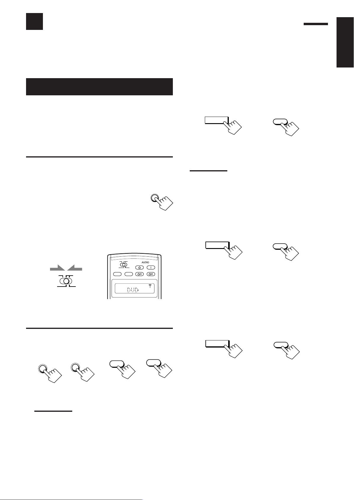
Using the Analog Multi-channel Playback Mode
DOOR
DOWN
ZONE 2
TRANSMITLEARN
ZONE 1
ON/OFF ON/OFF
STANDBY/ON STANDBY/ON
STANDBY
TV/CATV/DBS
VCR 1
ON
ZONE 2
TRANSMITLEARN
ZONE 1
ZONE 2
ZONE 1
ZONE 1
THX
THX
DSP
DVD MULTI
EXT 7.1CH
DVD MULTI
EXT 7.1CH
DSP
SURR/DSP
OFF
SURR/DSP
OFF
This receiver provides the DVD MULTI and EXT 7.1CH playback modes for reproducing the analog discrete output
mode of the DVD player or another component such as a digital decoder. Before using these playback modes, refer
also to the manual supplied for those components.
• The following operations are only possible when the receiver is ready for Zone 1 operations, and are used only
for the Zone 1 sources—“DVD MULTI” and “EXT 7.1CH.”
English
Activating the
Analog Multi-channel
Playback Modes
Perform the basic settings and adjustments using the Setup and
Adjustment Menus first (see pages 35 to 50).
Activating DVD MULTI or EXT 7.1CH playback mode
automatically recalls the memorized settings and adjustments.
• You also need to set the target component to the analog discrete
output mode.
IMPORTANT:
Check following before or while using the buttons and controls.
For Zone 1 operations:
The ZONE 1 ON/OFF lamp on the unit is lit.
• When using the unit:
–“ZONE 2” is not shown in the main display.
– Press DOOR DOWN to use the buttons inside the
front door.
To close the front door, press DOOR UP.
• When using the remote control:
– Set the ZONE 1/ZONE 2 (LEARN/TRANSMIT) selector to “ZONE 1.”
– Check the indication shown on the remote’s display when you
press a button on the remote control—this indicates the remote
control operation mode together with multi-room operation mode
(either ZONE 1 or ZONE 2) for a while.
3. Apply the THX mode or the DSP mode if
necessary.
• Press THX to apply the THX mode.
Each time you press the button, “THX U2 CINEMA” or
“THX MUSIC” will be activated.
On the unit
(inside the front door)
Note:
You cannot apply the THX mode in the following cases:
– When Analog Direct is turned on,
– When the Zone 2 speakers are activated, or
– When the surround back speakers are deactivated or only one
surround back speaker is used.
• Press DSP to apply one of the DSP modes (except
“STEREO FILM” and “MONO FILM”).
Each time you press the button, the DSP modes change in
sequence (see page 58 for details).
From the remote control
Ex. When you press DVD MULTI with
ZONE 1/ZONE 2 (LEARN/TRANSMIT) selector
set to “ZONE 1.”
1. Press DVD MULTI or EXT 7.1 CH.
On the unit
(inside the front door)
Note:
To view the pictures through a component connected to the EXT
7.1CH IN jacks, you need to follow one of the methods explained
on page 12.
From the remote control
On the unit
(inside the front door)
From the remote control
To adjust the speaker output level using the remote control,
see page 56.
To cancel the THX and DSP modes
Press SURR/DSP OFF.
“DSP OFF” appears on the display.
On the unit
(inside the front door)
From the remote control
2. Select the analog discrete output mode on the
connected component, and start playback.
• Refer to the manual supplied with the connected component.
60
Page 64

COMPU LINK Remote Control System
L
DGTL AUTO
LINEAR PCM
SPEAKERS
VOLUME
1
SUBWFR
R
dB
SPEAKERS
VOLUME
ZONE 2
1
dB
dB
PLAY
COMPU
LINK-4
(SYNCHRO)
AV
COMPU
LINK-
TEXT
COMPU
LINK
IR
OUT
IR
IN
CTRL
OUT
+12V
10mA MAX
DOOR
DOWN
ZONE 2
TRANSMITLEARN
ZONE 1
ZONE 2
TRANSMITLEARN
ZONE 1
The COMPU LINK remote control system allows you to operate JVC audio components through this receiver.
English
To use this remote control system, you need to connect JVC audio
components through the COMPU LINK (SYNCHRO) jacks (see
below) in addition to the connections using cables with RCA pin
plugs (see page 11).
• Make sure that the AC power cords of these components are
unplugged before connection. Plug the AC power cords only after
all connections are complete.
Cassette deck
or
MD recorder
CD recorder
RX-DP20VBK
Notes:
• There are four versions of COMPU LINK remote control system.
This receiver is equipped with the fourth version—COMPU LINK-4.
This version is created by adding systematic operations with the
CD recorder to the previous version—COMPU LINK-3.
• If your audio component has two COMPU LINK jacks, you can use
either one. If it has only one COMPU LINK jack, connect it so that it
is the last item in the series of components. (For example, the CD
recorder or CD player on the left column.)
• To operate the cassette deck or MD recorder using the COMPU
LINK remote control system, set the source name correctly. (See
page 27.)
• Refer also to the manuals supplied for your audio components.
This remote control system allows you to use the four functions
listed below.
Remote Control through the Remote Sensor on the
Receiver
You can control the connected audio components through the
receiver using this remote control. For details, see pages 71 and 72.
CD player
IMPORTANT:
Check the following before or while using the buttons and controls.
For Zone 1 operations:
The ZONE 1 ON/OFF lamp on the unit is lit.
For Zone 2 operations:
The ZONE 2 ON/OFF lamp on the unit is lit.
• When using the unit:
– For the Zone 1 operations: “ZONE 2” is not shown in the main
display.
– For the Zone 2 operations: “ZONE 2” is shown in
the main display.
– Press DOOR DOWN to use the buttons inside
the front door.
To close the front door, press DOOR UP.
• When using the remote control:
When operating the receiver using the remote control, the
display on the unit always shows the Zone 1 source
information though you are operating it for the Zone 2
source.
– Set the ZONE 1/ZONE 2 (LEARN/TRANSMIT) selector to “ZONE 1”
or “ZONE 2” correctly.
– Check the indication shown on the remote’s display when you
press a button—this indicates the remote control operation mode
together with multi-room operation mode (either ZONE 1 or
ZONE 2) for a while.
Automatic Source Selection
• When you press the play (
33
3) button on a connected component or
33
on its own remote control, the receiver automatically turns on and
changes the Zone 1 source to the component.
Ex. When you operate the CD player
– If the receiver is already turned on with the ZONE 2 ON/OFF lamp
on the unit lit and the source name for Zone 2 appears on the display,
the receiver changes the
Zone 2 source to the component.
Ex. When you operate the cassette deck
• When you press PLAY on the remote control
supplied for this receiver, the receiver
automatically turns on and changes the
Zone 1
source or Zone 2 source to the target component,
depending on the ZONE 1/ZONE 2 (LEARN/TRANSMIT)
selector setting on the remote control.
• When you select a new source on the receiver or on the remote
control supplied for this receiver either for
Zone 1 or Zone 2, the
newly selected component begins playing immediately, and the
previously selected source continues playing without sound for a
few seconds.
Note:
If the source changes from an analog source, for which Analog Direct
(see page 27) is activated, to a digital source, muting time* will be a
little longer.
*
The period during which the receiver changes the source
mechanically. No sound comes out during this period.
61
Page 65

Automatic Power On/Off (Standby): only possible with
the COMPU LINK-3 and COMPU LINK-4 connection
Automatic Power On:
• When you turn on the receiver by pressing (STANDBY/
ON) on the unit, or AUDIO
ZONE 1/ZONE 2 (LEARN/TRANSMIT) selector set to
“ZONE 1”:
When you turn on the Zone 1 sound by pressing ZONE 1 ON/
OFF while the receiver is turned on:
\ The ZONE 1 ON/OFF lamp lights up, and the source name for
Zone 1 appears on the display, and one of the connected
components will turn on automatically, depending on which
component has been previously selected as the
• When you turn on the receiver by pressing
AUDIO
(LEARN/TRANSMIT) selector set to “ZONE 2”:
When you turn on the Zone 2 sound by pressing
ZONE 2 ON/OFF while the receiver is turned on:
\ The ZONE 2 ON/OFF lamp lights up and one of the
Automatic Power Off (Standby):
• When you turn off the receiver by pressing
ON) on the unit, or AUDIO (STANDBY) on the remote
control, the connected components will turn off (standby).
• When you turn off the Zone 1 sound by pressing
ZONE 1 ON/OFF, the selected
off (unless the same component is selected as the Zone 2 source).
– If the ZONE 2 ON/OFF lamp is lit, the Zone 1 source will stop
playing, but will not turn off.
• When you turn off the Zone 2 source by pressing
ZONE 2 ON/OFF, the selected
off (unless the same component is selected as the Zone 1 source).
– If the ZONE 1 ON/OFF lamp is lit, the Zone 2 source will stop
playing, but will not turn off.
(ON) on the remote control, with ZONE 1/ZONE 2
connected components will turn on automatically, depending
on which component has been previously selected as the
2 source.
(ON) on the remote control with
OR
Zone 1 source.
OR
Zone
(STANDBY/
Zone 1 source component turns
Zone 2 source component turns
Synchronized Recording
This operation is only possible when the receiver is ready for
Zone 1 operations.
Synchronized recording means the cassette deck (or MD recorder)
starts recording as soon as a CD begins playing.
To use synchronized recording, follow these steps:
1. Put a tape in the cassette deck (or an MD in the
MD recorder), and a disc in the CD player.
2. Press the record (¶) button and the pause (8)
button on the cassette deck (or on MD recorder)
at the same time.
This puts the cassette deck (or MD recorder) into recording
pause.
If you do not press the record (¶) button and pause (8) button at
the same time, the synchronized recording feature will not
operate.
3. Press the play (3) button on the CD player.
The Zone 1 source changes on the receiver, and as soon as play
starts, the cassette deck (or MD recorder) starts recording. When
play ends, the cassette deck (or MD recorder) enters recording
pause, and stops about 4 seconds later.
Notes:
• During synchronized recording;
– The selected Zone 1 source cannot be changed. (You can
change the Zone 2 source.)
– If the same source is selected both for Zone 1 and Zone 2,
operating the Zone 2 source will affect the recording.
• The COMPU LINK remote control system may not operate properly
during synchronized recording;
– If the power of any component is shut off.
– If the Zone 1 sound is turned off by pressing ZONE 1 ON/OFF.
In this case, you must start recording again from the beginning.
English
62
Page 66

TEXT COMPU LINK Remote Control System
COMPU
LINK-4
(SYNCHRO)
AV
COMPU
LINK-
TEXT
COMPU
LINK
IR
OUT
IR
IN
CTRL
OUT
+12V
10mA MAX
COMPU
LINK-4
(SYNCHRO)
AV
COMPU
LINK-
TEXT
COMPU
LINK
IR
OUT
IR
IN
CTRL
OUT
+12V
10mA MAX
The TEXT COMPU LINK remote control system has been developed to deal with the disc information recorded in the
*
CD Text
COMPU LINK remote control system through the receiver.
English
and MDs. Using this information in the discs, you can operate the CD player or MD recorder with the TEXT
CONNECTIONS
To use this remote control system, you need to connect the CD
player and/or MD recorder you want to operate, following the
procedures below.
1. If you have already plugged your CD player, MD
recorder, and this receiver into the AC outlets,
unplug their AC power cords first.
2. Connect your CD player, MD recorder, and this
receiver as follows through the COMPU LINK
jacks and TEXT COMPU LINK jacks.
1) COMPU LINK jacks: Use cables with monaural mini-
plugs (not supplied with this receiver).
CD player
RX-DP20VBK
MD recorder
FUNCTIONS
This remote control system allows you to use the functions listed
below.
Displaying the Disc Information on the TV screen
Disc information such as its performer and disc title (and track titles
only when a CD Text is selected) is shown on the TV screen.
Disc Search: Only for CD Player
This remote control system allows you to search for discs by the
performer, disc title, and music genre.
With this disc search, you can easily find the disc you want to play.
Disc Title Input
If your CD player or MD recorder has the disc memory function,
you can input the following information about the normal audio CDs
or MDs on the TV screen.
• For CDs: Performer, disc title, and music genre
• For MDs: Disc title and song titles
*
What is a CD Text?
In a CD Text, some information about the disc (its disc title, performer,
composer, arranger, etc.) is recorded.
2) TEXT COMPU LINK jacks: Use cables with stereo mini-
plugs (not supplied with this receiver).
CD player
RX-DP20VBK
MD recorder
3. Connect your CD player, MD recorder, and this
receiver using the cables with RCA pin plugs (see
page 11).
4. Plug the AC power cords of these components
above into the AC outlets.
Notes:
• If your audio component has two COMPU LINK jacks, you can use
either one. If it has only one COMPU LINK jack, connect it so that it
is the last item in the series of components. (For example, the CD
player in the diagram on the left column.)
• If your audio component has two TEXT COMPU LINK jacks, you
can use either one. If it has only one TEXT COMPU LINK jack,
connect it so that it is the last item in the series of components. (For
example, the CD player in the diagram on the left column.)
•“TEXT COMPULINK SOURCE NOT CONNECTED” appears on the
display in the following cases:
– When the connections explained on the left are not correctly
done.
– When you try to use the TEXT COMPU LINK function a few
seconds after you turn on the connected equipment. This is not a
malfunction of the units.
• Refer also to the manuals supplied with your CD player or MD
recorder.
IMPORTANT:
If you turn on the receiver before turning on the other components
after connecting the components, the TEXT COMPU LINK remote
control system does not work correctly.
If this happens:
1. Turn off all the components including this receiver.
2. Turn on the connected components.
3. Turn on this receiver.
5. When turning on these components for the first
time, turn on the connected components first,
then turn on this receiver.
63
Page 67

OPERATIONS
ZONE 2
TRANSMITLEARN
ZONE 1
ON/OFF ON/OFF
STANDBY/ON STANDBY/ON
STANDBY
TV/CATV/DBS
VCR 1
ON
ZONE 2
TRANSMITLEARN
ZONE 1
ZONE 2
ZONE 1
ZONE 1
ON/OFF ON/OFF
STANDBY/ON STANDBY/ON
STANDBY
TV/CATV/DBS
VCR 1
ON
ZONE 2
TRANSMITLEARN
ZONE 1
ZONE 2
ZONE 1
ZONE 2
SET
EXIT
TEXT
DISPLAY
ZONE 2
TRANSMITLEARN
ZONE 1
1
2
3
4
5
7
6
8
9
To use this remote control system, you need to connect the Zone 1
TV to the MONITOR OUT jack (see page 14) and the Zone 2 TV
to the ZONE 2 MONITOR OUT jack (see page 19), and set the
TV’s input mode to the proper position to which the receiver is
connected.
Make sure you have connected the CD player or MD recorder
equipped with the TEXT COMPU LINK remote control system.
If not, you cannot use the following functions.
IMPORTANT:
Check the following before or while using the buttons and controls.
• When using the remote control:
– Set the ZONE 1/ZONE 2 (LEARN/TRANSMIT) selector to “ZONE 1”
or “ZONE 2” correctly.
– Check the indication shown on the remote’s display when you
press a button—this indicates the remote control operation mode
together with multi-room operation mode (either ZONE 1 or
ZONE 2) for a while.
Ex. When you press TEXT
DISPLAY with ZONE 1/
ZONE 2 (LEARN/
TRANSMIT) selector set
to “ZONE 1.”
Ex.When you press TEXT
DISPLAY with ZONE
1/ZONE 2 (LEARN/
TRANSMIT) selector
set to “ZONE 2.”
Showing the Disc Information on the TV
Screen (Either in Zone 1 or in Zone 2)
Press TEXT DISPLAY while “CD” or “MD” is
selected as the source.
The Disc Information screen appears on the TV.
Disc Information screen
1 Source name: CD or MD
2 Select
3 Track numbers and track titles.
• When you move to a track number, you can change the
track information by pressing @ / #. Each time you press the
button, track information alternates between its track title and
its performer. (You can also start playing the track by pressing
SET.)
4 Select this (move
DISC SEARCH screen (see page 65).
5 Select this (move
TITLE INPUT screen (see page 66).
6 This appears only when a CD Text is selected.
7 Disc information such as the disc title, performer, music genre,
etc.
When this is selected (
information by pressing @ / #. Each time you press the button,
disc information (see “Note on 7”) changes.
8 Select
9 Usable buttons and their functions for the current selection.
Indication here will change according to what is currently
selected (
or , then press SET to change the disc.
in front), then press SET to go to the
in front), then press SET to go to the
in front), you can change the disc
or , then press SET to change the track.
in front) on the screen. See “Note on 9.”
English
Note on 7:
The following information will appear on the display:
• For CD Texts—Disc title, Performer, Genre, Song writer, Composer,
Text display operation buttons
Arranger, Message
Only recorded information will be shown. If there is no data,
“NO DATA” will appear.
• For MDs—Disc title
If there is no data, “NO DATA” will appear.
Note on 9:
For example, the SET button will be used to start play (PLAY), to go to
the next screen (ENTER), and to determine the selection (ENTER).
To exit from the Disc information screen
Press EXIT.
Notes:
• The on-screen display will disappear in the following cases:
– if no operation is done for about 10 minutes.
– if you do any operation other than explained in this section.
• To control the MD recorder using the TEXT COMPU LINK remote
control system, you have to change the source name shown on the
display from “TAPE” to “MD.” (See page 27.)
• Some special characters and marks cannot be displayed correctly.
64
Page 68

Searching for a Disc (Only for the CD player)
Search for a disc by its performer:
English
1. Press TEXT DISPLAY while “CD” is selected as
the source.
The Disc Information screen appears on the TV.
2. Press % / fi to move to “SEARCH,” then press
SET.
The DISC SEARCH screen appears.
3. Press % / fi to move
to “PERFORMER,”
then press SET.
The PERFORMER SEARCH
screen appears.
4. Press % / fi / @ / # to
move
in front of the
first character of the
performer you want to
search for, then press
SET.
To correct an incorrect
entry, press % / fi / @ / # to move
character, then press SET.
Note:
Symbols such as @, # or $ are not available for search.
in front of the correct
5. Press SET again.
Disc search starts, then the
SEARCH RESULT screen,
showing the performers,
appears.
Search for a disc by its disc title:
1. Press TEXT DISPLAY while “CD” is selected as
the source.
The Disc Information screen appears on the TV.
2. Press % / fi to move to “SEARCH,” then press
SET.
The DISC SEARCH screen appears.
3. Press % / fi to move
to “DISC TITLE,”
then press SET.
The DISC TITLE SEARCH
screen appears.
4. Press % / fi / @ / # to
move
in front of the
first character of the
disc title you want to
search for, then press
SET.
To correct an incorrect
entry, press % / fi / @ / # to move in front of the correct
character, then press SET.
Note:
Symbols such as @, # or $ are not be available for search.
5. Press SET again.
Disc search starts, then the
SEARCH RESULT screen,
showing the disc titles,
appears.
6. On the SEARCH RESULT screen, you can do the
following:
• Changing the indication of the disc information:
Press % / fi to move
@ / #. Each time you press @ / #, the disc information
alternates between its performer and its disc title.
• Starting a disc play and going to the Disc Information
screen (see page 64): Press % / fi to move to a searched
disc, then press SET.
• Showing unseen disc information (if more than 5 discs are
listed as a result of the search): Press % / fi until they
appear.
• Going back to the PERFORMER SEARCH screen: Press
EXIT.
to a searched disc, then press
6. On the SEARCH RESULT screen, you can do the
following:
• Changing the indication of the disc information:
Press % / fi to move to a searched disc, then press
@ / #. Each time you press @ / #, the disc information
alternates between its disc title and its performer.
• Starting a disc play and going to the Disc Information
screen (see page 64): Press % / fi to move
disc, then press SET.
• Showing unseen disc information (if more than 5 discs are
listed as a result of the search): Press % / fi until they
appear.
• Going back to the DISC TITLE SEARCH screen: Press
EXIT.
to a searched
65
Page 69

Search for a disc by its genre:
1. Press TEXT DISPLAY while “CD” is selected as
the source.
The Disc Information screen appears on the TV.
2. Press % / fi to move to “SEARCH,” then
press SET.
The DISC SEARCH screen appears.
3. Press % / fi to move
to “GENRE,” then
press SET.
The GENRE SEARCH
screen appears.
4. Press % / fi to move
to the genre you
want to search for,
then press SET.
To show the unseen genres,
press % / fi until they appear.
Disc search starts, then the
SEARCH RESULT screen, showing the disc titles, appears.
Entering the Disc Information
For a CD Player with disc memory function:
You can use the disc memory function through this receiver.
The disc information (its performer, disc title, and music genre) of
normal audio CDs will be stored into the memory built in the CD
player.
For the disc memory function, refer to the manual supplied with your
CD player.
• The performer, disc title, and music genre information are usually
recorded on a CD Text. However, if a CD Text has no genre
information recorded on the disc itself, you can input its music
genre yourself.
Note:
You can enter the TITLE INPUT screens for a CD Text and input its
titles. However, you cannot store the titles you have input for a CD
Te xt .
Example: Entering the following information for Disc 1
Performer: “MICHAEL”
Disc title: “MY FAVORITE”
1. Press TEXT DISPLAY while “CD” is selected as
the source.
The Disc Information screen appears on the TV.
English
5. On the SEARCH
RESULT screen, you
can do the following:
• Changing the indication
of the disc information:
Press % / fi to move
a searched disc, then press
@ / #. Each time you press @ / #, the disc information
alternates between its disc title and its performer.
• Starting a disc play and going to the Disc Information
screen (see page 64): Press % / fi to move
disc, then press SET.
• Showing unseen disc information (if more than 5 discs are
listed as a result of the search): Press % / fi until they
appear.
• Going back to the GENRE SEARCH screen: Press EXIT.
to
to a searched
2. Press % / fi to move to “TITLE INPUT,” then
press SET.
The TITLE INPUT: PERFORMER screen appears.
3. Press % / fi / @ / # to
move
in front of a
character you want,
then press SET to enter
the character.
• If the current CD is a CD
Text, go to step 5 without
entering the performer.
To use lower-case letters, press % / fi / @ / # to move
, then press SET.
To use upper-case letters again, press % / fi / @ / # to move
to , then press SET.
to
66
Page 70

4. Repeat step 3 until you
English
finish entering a
performer name (up to
32 characters).
To insert a space, press
% / fi / @ / # to move
, then press SET.
To correct an incorrect character:
1) Press % / fi / @ / # to move to + or =, then press
SET until the incorrect character is selected.
2) Press % / fi / @ / # to move
to erase the character.
3) Press % / fi / @ / # to move
character, then press SET to enter the correct character.
5. Press % / fi / @ / # to
move
to “DISC 1:
MICHAEL (in this
example),” then press
SET.
The TITLE INPUT: DISC
TITLE screen appears.
For the MD recorder:
You can write the disc information (disc title and song titles) into the
disc. You can only write the song title for the song currently
selected.
• If you have the CD-MD combination deck, you can also enter the
to
to , then press SET
in front of the correct
disc information (its performer, disc title, and its music genre) of
normal audio CDs into the memory built in the CD-MD
combination deck. (To do this, follow the procedure of “For a CD
Player with disc memory function” on page 66.)
• If you change the disc or song title including more than 32
characters, the characters following the 32nd will be erased from
the title.
1. Press TEXT DISPLAY while “MD” is selected as
the source.
The Disc Information screen appears on the TV.
2. Press % / fi to move
to “TITLE INPUT,”
then press SET.
The DISC TITLE INPUT
screen appears.
6. Enter the disc title,
referring to steps 3
and 4.
• If the current CD is a CD
Text, go to the next step
without entering the disc
title.
7. Press % / fi / @ / # to
move
to “DISC 1:
MY FAVORITE (in this
example),” then press
SET.
The TITLE INPUT: DISC 1
GENRE screen appears.
8. Press % / fi to move to the genre you want,
then press SET.
The Disc Information screen appears again.
To show the unseen genres, press % / fi until they appear.
3. Enter the title, referring
to steps 3 and 4 of “For
a CD Player with disc
memory function:” on
pages 66 and 67.
• You can enter up to 32
characters for the disc title.
4. Press % / fi / @ / # to
move
to the disc title
you have just entered,
then press SET.
The disc title is stored into the
memory, and the SONG
TITLE INPUT screen for the
currently selected song
appears.
• You can enter a song title for the song currently selected.
5. Enter the song title, referring to steps 3 and 4 of
“For a CD Player with disc memory function” on
pages 66 and 67.
• You can enter up to 32 characters for the song title.
67
6. Press % / fi / @ / # to move to the song title
you have just entered, then press SET.
The song title is stored into the memory, and the Disc
Information screen appears again.
Page 71

AV COMPU LINK Remote Control System
COMPU
LINK-4
(SYNCHRO)
AV
COMPU
LINK-
TEXT
COMPU
LINK
IR
OUT
IR
IN
CTRL
OUT
+12V
10mA MAX
AV
COMPU LINK
VHS
AV
COMPU LINK
AV
COMPU LINK
EX
DVD
AV
COMPU LINK III
Less than 3 m (10 feet)
At an angle of
approx. 60°
COMPU
LINK-4
(SYNCHRO)
AV
COMPU
LINK-
TEXT
COMPU
LINK
IR
OUT
IR
IN
CTRL
OUT
+12V
10mA MAX
This receiver is equipped with the AV COMPU LINK-III. The AV COMPU LINK remote control system allows you to
operate JVC video components (TV, VCR, and DVD player) through the receiver. To use this remote control system, you
need to connect the video components you want to operate, following the procedure below.
• Refer also to the manuals supplied with your video components.
1. If you have already plugged your VCR 1 (VCR connected to the VCR 1 jacks), DVD player, TV, and this
receiver into the AC outlets, unplug their AC power cords first.
2. Connect the IR signal transmitter (supplied) to the IR OUT on the rear, and place it so that it is aimed at
the remote sensor(s) on the target video component(s).
• See “CONNECTIONS 1” below (and page 17 for details).
3. Connect your VCR 1, DVD player, TV, and this receiver as follows, using cables with monaural mini-plugs
(not supplied).
• See “CONNECTIONS 2” below.
4. Connect the audio input/output jacks on VCR 1, DVD player, TV, and this receiver using the cables with
RCA pin plug.
• See pages 13 to 15.
5. Connect the video input/output jacks on VCR 1, DVD player, TV, and this receiver, using the cables with
RCA pin plugs, with S-video plugs or with component video plugs.
• See “CONNECTIONS 3” on the next page (and pages 13 to 15 for details).
6. Plug the AC power cords of the components into the AC outlets.
English
7. When turning on the TV for the first time after the AV COMPU LINK connection, turn the TV volume to
the minimum using the TV volume control on the TV.
8. Turn on the other connected components first, then turn on this receiver.
• When turning on the VCR 1, use the remote control supplied with this receiver—press VCR 1 (STANDBY/ON).
CONNECTIONS 1: IR Signal Transmitter Connection
Target video component(s)
IR signal transmitter
CONNECTIONS 2: AV COMPU LINK Connection
VCR 1
DVD player
RX-DP20VBK
On the rear panel
TV
RX-DP20VBK
CAUTION:
When connecting the TV with the
AV COMPU LINK remote control
system, connect the receiver to
the AV COMPU LINK EX or AV
COMPU LINK III terminal.
DO NOT connect the receiver to
the AV COMPU LINK RECEIVER/
AMP terminal.
Notes:
• The AV COMPU LINK remote control system cannot control the DBS tuner connected to the TV SOUND/DBS IN jacks, and video
components connected to the VIDEO and VCR 2 IN jacks on the receiver.
• When connecting only the VCR 1 or DVD player to this receiver, connect it directly to the receiver using a cable with the monaural miniplugs.
• When connecting the receiver and the TV with AV COMPU LINK EX terminal by using the component video cables, you cannot use
Automatic Selection of TV’s Input Mode (see page 70).
68
Page 72

DVD
CONNECTIONS 3: Video Cable Connection
English
This receiver is equipped with video signal conversion function (for details, see “IMPORTANT” on page 12). However, with the AV COMPU
LINK remote control system, video conversion function cannot be used. So, connect the VCR and/or DVD player to the TV using only one
of the following three ways:
• The video input terminal should be correctly preset (see “p Setting the Video Input Terminals—VIDEO INPUT” on page 43);
otherwise, the correct input for this receiver will not be selected on the TV.
When connecting the source equipment to the receiver through the S-video jacks, connect this receiver to the
TV’s Video Input 1 terminal using S-video cables.
CASE 1
When connecting the source equipment to the receiver through the composite video jacks, connect this receiver
to the TV’s Video Input 2 terminal (composite video input) using composite video cables.
CASE 2
When connecting the source equipment to the receiver through the component video jacks, connect this
receiver to the TV’s Video Input 2 terminal (component video input) using component video cables.
CASE 3
The AV COMPU LINK remote control system allows you to use the
five basic functions listed below.
Source
Equipment
Source
Equipment
Source
Equipment
S-video cable
Composite
video cable
Component
video cable
Remote Control of the TV, DVD player, and VCR Using
This Remote Control
IMPORTANT:
To operate the video components using the IR signal transmitter
(supplied), place it so that it is aimed at the remote sensor(s) on the
target video component(s).
• The IR signal transmitter can send signals at a distance of 3 m (10
feet).
DVD player
TV
RX-DP20VBK
You can control the connected video components using this remote
control. Aim the remote control at the remote sensor(s) on the target
video component(s) or on the receiver directly.
For details, see page 73.
VCR
RX-DP20VBK
RX-DP20VBK
RX-DP20VBK
S-video cable
Composite
video cable
Component
video cable
TV
To Video Input 1
TV
To Video Input 2
TV
To Video Input 2
One-Touch Video Play
• Simply by inserting a video cassette without its safety tab into the
VCR 1 (the VCR connected to the VCR 1 jacks), you can watch
the video playback without setting other switches manually.
The receiver automatically turns on and changes the
source to “VCR 1.”
The Zone 1 TV automatically turns on and changes the input
mode to the appropriate position so that you can view the playback
picture.
When you insert a video cassette with its safety tab in place, press
the play (
you can get the same result.
– If the receiver is already turned on with the ZONE 2 ON/OFF
• When you press PLAY on the remote control supplied for this
receiver for operating the VCR 1, the receiver automatically turns
on and changes the
“VCR 1”—depending on the ZONE 1/ZONE 2 (LEARN/
TRANSMIT) selector setting on the remote control.
– For Zone 1 operations only: The Zone 1 TV automatically turns
33
3) button on the VCR 1 or on its remote control. Thus,
33
lamp on the unit is lit and the source name for Zone 2 appears on
the display, the receiver changes the
(In this case, the Zone 2 TV will not turn on.)
Zone 1 source or Zone 2 source to
on and changes the input mode to the appropriate position so
that you can view the picture.
Zone 2 source to “VCR 1.”
Zone 1
69
Page 73

One-Touch DVD Play
Simply by starting playback on the DVD player, you can enjoy the
DVD playback without setting other switches manually.
When you press PLAY on the remote control supplied for this
receiver for operating the DVD player, the receiver automatically
turns on and changes the
Zone 1 source or Zone 2 source,
depending on the ZONE 1/ZONE 2 (LEARN/TRANSMIT) selector
setting on the remote control, to the appropriate input—“DVD” or
“DVD MULTI” as the Zone 1 source, and “DVD” as the Zone 2
source.
For Zone 1 operations: The Zone 1 TV automatically turns on and
changes the input mode to the appropriate position so that you can
view the playback picture.
• When the DVD player is connected through the analog input jacks
on this receiver (and analog input is selected), the receiver
automatically turns on and changes the source to “DVD” or “DVD
MULTI.”
– If the receiver is already turned on with the ZONE 2 ON/OFF
lamp on the unit lit, and Zone 2 source name is shown on the
display, the receiver changes the
Zone 2 source to “DVD.” In
this case, the Zone 2 TV will not turn on.
• When the DVD player is connected through the digital input
terminal on this receiver (and digital input is selected), the
receiver automatically turns on and changes the Zone 1 source to
“DVD.”
– If the receiver is already turned on with the ZONE 2 ON/OFF
lamp on the unit lit, and Zone 2 source name is shown on the
display, the receiver changes the
Zone 2 source to “DVD.” (If
no analog connection is made for the DVD player, no sound
comes out of the Zone 2 front speakers).
Automatic Selection of TV’s Input Mode (Only for Zone 1
Operations)
• When you select “TV” as the Zone 1 source to play on the
receiver, the Zone 1 TV automatically changes the input mode to
the TV tuner so that you can watch the Zone 1 TV.
• When you select “DVD,” “DVD MULTI,” “VCR 1,” “VCR 2,”
“VIDEO” or “DBS” as the
Zone 1 source to play on the receiver,
the Zone 1 TV automatically changes the input mode to the
appropriate position (either Video Input 1 or Video Input 2) so that
you can view the playback picture.
Notes:
• When you select “TV” as the source on the receiver, you cannot
see the menu on the TV screen since the AV COMPU LINK remote
control system automatically changes the TV’s input mode to the
TV tuner.
If you do not mind stopping listening to the TV sounds, you can
then show the on-screen displays after changing the TV’s input
mode to the appropriate position (either Video Input 1 or Video
Input 2) the receiver is connected to.
• This function does not work when you connect this receiver and the
TV with the AV COMPU LINK EX terminal using the component
video cables. To use this function, connect this receiver and the TV
using the S-video or composite video cables.
Automatic Power On/Off (Standby)
Automatic Power On:
The Zone 1 TV, VCR 1 (the VCR connected to the VCR 1 jacks),
and DVD player turn on and off along with the receiver.
• When you turn on the receiver by pressing
(STANDBY/
ON) on the front panel, or AUDIO (ON) on the remote
control with the ZONE 1/ZONE 2 (LEARN/TRANSMIT)
selector set to “ZONE 1”:
OR
When you turn on the Zone 1 sound by pressing
ZONE 1 ON/OFF while the receiver is turned on:
The ZONE 1 ON/OFF lamp on the unit lights up and the source
name for Zone 1 appears on the display, and;
– If the previously selected
Zone 1 source is “VCR 1,” the Zone 1
TV and VCR 1 will turn on automatically.
– If the previously selected
Zone 1 source is “DVD” or “DVD
MULTI,” the Zone 1 TV and DVD player will turn on
automatically.
– If the previously selected
Zone 1 source is “VIDEO,” “VCR 2,”
“TV” or “DBS,” only the Zone 1 TV will turn on automatically.
• When you turn on the receiver by pressing
AUDIO
(ON) on the remote control with the ZONE 1/ZONE
2 (LEARN/TRANSMIT) selector set to “ZONE 2”:
OR
When you turn on the Zone 2 sound by pressing
ZONE 2 ON/OFF while the receiver is turned on:
The ZONE 2 ON/OFF lamp lights up, and —
– If the previously selected Zone 2 source is “VCR 1,” the VCR 1
will turn on automatically.
– If the previously selected
Zone 2 source is “DVD,” the DVD
player will turn on automatically.
– If the previously selected Zone 2 source is “VIDEO,” “VCR 2,”
or “DBS,” nothing happens.
Automatic Power Off (Standby):
• When you turn off the receiver by pressing
ON) on the unit or AUDIO
(STANDBY) on the remote
(STANDBY/
control, the Zone 1 TV, VCR 1 and the DVD player will turn off
(standby).
• When you turn off the Zone 1 sound by pressing
ZONE 1 ON/OFF, the selected
Zone 1 source component turns
off (unless the same component is selected as the Zone 2 source),
and the Zone 1 TV also turns off.
– If the ZONE 2 ON/OFF lamp is lit, nothing happens.
• When you turn off the Zone 2 sound by pressing
ZONE 2 ON/OFF, the selected
Zone 2 source component turns
off (unless the same component is selected as the Zone 1 source).
– If the ZONE 1 ON/OFF lamp is lit, nothing happens.
Note:
If you turn off the receiver by pressing
unit or AUDIO (STANDBY) on the remote control, or if you turn off
the Zone 1 sound by pressing ZONE 1 ON/OFF while recording on
the VCR 1, the VCR 1 will not turn off, but continue recording.
(STANDBY/ON)
on the
English
70
Page 74

Operating JVC’s Audio/Video Components
ZONE 2
TRANSMITLEARN
ZONE 1
ON/OFF ON/OFF
STANDBY/ON STANDBY/ON
STANDBY
TV/CATV/DBS
VCR 1
ON
ZONE 2
TRANSMITLEARN
ZONE 1
ZONE 2
ZONE 1
ZONE 1
ON/OFF ON/OFF
STANDBY/ON STANDBY/ON
STANDBY
TV/CATV/DBS
VCR 1
ON
ZONE 2
TRANSMITLEARN
ZONE 1
ZONE 2
ZONE 1
ZONE 2
ZONE 2
TRANSMITLEARN
ZONE 1
You can operate JVC’s audio and video components with this receiver’s remote control, since control signals for JVC
components are preset in the remote control.
English
Operating Audio Components
IMPORTANT:
To operate JVC’s audio components using this remote control:
• You need to connect JVC’s audio components through the COMPU
LINK (SYNCHRO) jacks (see page 61) in addition to the
connections using cables with RCA pin plugs (see page 11).
• Aim the remote control directly at the remote sensor on the
receiver.
• To operate a source with the remote control, the source must be
selected using source selecting buttons on the remote control.
• To operate the cassette deck or MD recorder using the COMPU
LINK remote control system, set the source name correctly. (See
page 27.)
• Refer also to the manuals supplied with your components.
When using the remote control:
– Set ZONE 1/ZONE 2 (LEARN/TRANSMIT) selector to “ZONE 1” or
“ZONE 2” correctly.
– Check the indication shown on the remote’s display when you press
a button—this indicates the remote control operation mode together
with multi-room operation mode (either ZONE 1 or ZONE 2) for a
while.
– The CONTROL button can change the remote control operation
mode without changing the source.
Each time you press the button, the remote control operation mode
changes in the sequence—
to the beginning).
Ex. When you press FM/AM
with ZONE 1/ZONE 2
(LEARN/TRANSMIT)
selector set to “ZONE 1.”
VCR1 = TAPE = CDR = CD DISC =
Ex. When you press FM/AM
with ZONE 1/ZONE 2
(LEARN/TRANSMIT)
selector set to “ZONE 2.”
(back
Tuner
You can always perform the following operations:
FM/AM : Tunes in to the last station of the last
selected band. Each time you press the
button, the band alternates between FM
and AM.
After pressing FM/AM, you can perform the following operations:
1 – 10, +10 : Selects a preset channel number directly.
For channel number 5, press 5.
For channel number 15, press +10, then 5.
For channel number 20, press +10, then 10.
TUNING UP/DOWN : Tunes in to stations.
FM MODE : Changes the FM reception mode.
Sound control section (Amplifier)
You can always perform the following operations:
THX : Selects the THX modes.
SURROUND : Selects the Surround modes
EX/ES/7.1 : Selects the 7.1-channel reproduction
modes.
DSP : Selects the DSP modes.
SURR/DSP OFF : Deactivates the THX/Surround/DSP
modes.
ANALOG DIRECT : Turns on or off Analog Direct.
ANALOG/DIGITAL INPUT : Selects the analog/digital inputs.
CC CONVERTER : Turns on or off CC Converter.
After pressing SOUND, you can perform the following operations:
TEST : Turns on or off the test tone output.
FRONT•L then LEVEL +/– : Adjusts the left front speaker
channel output level.
FRONT•R then LEVEL +/– : Adjusts the right front speaker
channel output level.
SUBWFR then LEVEL +/– : Adjusts the subwoofer output level.
CENTER then LEVEL +/– : Adjusts the center speaker channel
output level.
SURR•L then LEVEL +/– : Adjusts the left surround speaker
channel output level.
SURR•R then LEVEL +/– : Adjusts the right surround speaker
channel output level.
SURR BK•L then LEVEL +/– :
Adjusts the left surround back
speaker channel output level.
SURR BK•R then LEVEL +/– :
Adjusts the right surround back
channel speaker output level.
EFFECT : Selects the effect level.
LIVENESS : Selects the liveness.
71
Notes:
• After adjusting sounds, press the corresponding source selecting
button to operate your target source by using the 10 keys;
otherwise, the 10 keys cannot be used for operating your target
source.
• When you press LEVEL + or LEVEL –, the corresponding speaker
name appears on the remote’s display.
Page 75

CD player
After pressing CD, you can perform the following operations on the
CD player:
PLAY : Starts playing.
4 : Returns to the beginning of the current (or
previous) track.
¢ : Skips to the beginning of the next track.
STOP : Stops playing.
PAUSE : Pauses playing. To release, press PLAY.
1 – 10, +10 : Selects a track number directly.
For track number 5, press 5.
For track number 15, press +10, then 5.
For track number 20, press +10, then 10.
For track number 30, press +10, +10, then 10.
CD player-changer
After selecting “CD DISC” by pressing CONTROL repeatedly, you
can perform the following operations on a CD player-changer:
PLAY : Starts playing.
4 : Returns to the beginning of the current (or
previous) track.
¢ : Skips to the beginning of the next track.
STOP : Stops playing.
PAUSE : Pauses playing. To release, press PLAY.
1 – 6, 7/P : Selects the number of a disc installed in a CD
player-changer.
After pressing CD, you can perform the following operations on the
CD player-changer:
1 – 10, +10 : Selects a track number directly.
For track number 5, press 5.
For track number 15, press +10, then 5.
For track number 20, press +10, then 10.
For track number 30, press +10, +10, then 10.
EXAMPLE:
• Selecting disc number 4, track number 12, and starting playback.
1.Press CONTROL repeatedly until “CD DISC” appears on
the remote’s display, then press 4.
2.Press CD, then press +10, 2.
If your CD changer is of 200-disc loading capability (except for
XL-MC100 and XL-MC301)
You can do the following operations using the 10 keys after pressing
CD:
1. Select a disc number.
2. Then select a track number (always enter two digits).
3. Start playback.
EXAMPLES:
• Selecting disc number 3, track number 2, and starting playback.
Press 3, then, 0, 2, then PLAY.
• Selecting disc number 10, track number 5, and starting playback.
Press 1, 0, then, 0, 5, then PLAY.
• Selecting disc number 105, track number 12, and starting
playback. Press 1, 0, 5, then 1, 2 then PLAY.
CD recorder
After pressing CDR or selecting “CDR” by pressing CONTROL
repeatedly, you can perform the following operations on a CD
recorder:
PLAY : Starts playing.
4 : Returns to the beginning of the current (or
¢ : Skips to the beginning of the next track.
STOP : Stops playing.
PAUSE : Pauses playing. To release, press PLAY.
1 – 10, +10 : Selects a track number directly.
previous) track.
For track number 5, press 5.
For track number 15, press +10, then 5.
For track number 20, press +10, then 10.
For track number 30, press +10, +10, then 10.
Note:
When you start recording on the CD recorder, use the buttons on the
CD recorder itself or on the remote control supplied for it.
Cassette deck
After pressing TAPE/MD or selecting “TAPE” by pressing
CONTROL repeatedly, you can perform the following operations on
a cassette deck:
PLAY : Starts playing.
REW : Fast-winds the tape from right to left.
FF : Fast-winds the tape from left to right.
STOP : Stops operations.
PAUSE : Pauses playing. To release, press PLAY.
¶ REC : Press this button together with the PLAY button to
start recording (for Zone 1 operation only).
Press this button together with the PAUSE button to
enter recording pause (for Zone 1 operation only).
Note:
When connecting the cassette recorder to the TAPE/MD IN jacks,
change the source name to “TAPE”—initial setting (see page 27).
MD recorder
After pressing TAPE/MD or selecting “TAPE*” by pressing
CONTROL repeatedly, you can perform the following operations on
the MD recorder:
PLAY : Starts playing.
4 : Returns to the beginning of the current (or previous)
track.
¢ : Skips to the beginning of the next track.
STOP : Stops playing.
PAUSE : Pauses playing. To release, press PLAY.
¶ REC : Press this button together with the PLAY button to
start recording (for Zone 1 operation only).
Press this button together with the PAUSE button to
enter recording pause (for Zone 1 operation only).
Notes:
• When connecting an MD recorder to the TAPE/MD IN jacks, change
the source name to “MD” (see page 27).
*
Selecting “TAPE” will allow you to control the MD recorder.
English
Turntable
After pressing PHONO, you can perform the following operations
on a turntable:
PLAY : Starts playing.
STOP : Stops operations.
72
Page 76

Operating Video Components
TV
CATV/
DBS
ZONE 2
TRANSMITLEARN
ZONE 1
ZONE 2
TRANSMITLEARN
ZONE 1
ON/OFF ON/OFF
STANDBY/ON STANDBY/ON
STANDBY
TV/CATV/DBS
VCR 1
ON
ZONE 2
TRANSMITLEARN
ZONE 1
ZONE 2
ZONE 1
ZONE 1
ON/OFF ON/OFF
STANDBY/ON STANDBY/ON
STANDBY
TV/CATV/DBS
VCR 1
ON
ZONE 2
TRANSMITLEARN
ZONE 1
ZONE 2
ZONE 1
ZONE 2
SET
DVD
MENU
English
IMPORTANT:
To operate JVC’s video components using this remote control:
• You need to connect JVC’s video components through the AV
COMPU LINK jacks (see page 68) in addition to the connections
using cables with RCA pin plugs (see pages 13 to 15).
• Some JVC VCRs can accept two types of control signals—remote
codes “A” and “B.” Before using this remote control, make sure that
the remote control code of the VCR connected to the VCR 1 IN
jacks is set to code “A.”
– When another JVC VCR is connected to the VCR 2 IN and
VIDEO jacks, set its remote control code to code “B.” (This
remote control cannot emit the control signals of code “B.”)
• To operate the video component(s) using the remote control:
– Aim the remote control directly at the remote sensor on each
component, not on the receiver.
• To operate the video component(s) using the RF signals emitted
from this remote control, the IR signal transmitter and the RF rod
antenna must be connected to this receiver.
– Place the IR signal transmitter so that it is aimed at the remote
sensor(s) on the target video component(s).
– The RF signal-reachable distance may differ depending on the
operating conditions and circumstances.
– The IR signal transmitter can send signals from a distance of 3 m
(10 feet).
When using the remote control:
– Set the ZONE 1/ZONE 2 (LEARN/TRANSMIT) selector to “ZONE 1”
or “ZONE 2” correctly.
– Set the TV operation mode selector to “TV” or
“CATV/DBS” properly.
To operate TV, set it to “TV.”
– Check the indication shown on the remote’s display
when you press a button—this indicates the remote
control operation mode together with multi-room operation mode
(either ZONE 1 or ZONE 2) for a while.
– The CONTROL button can change the remote control operation
mode without changing the source.
Each time you press the button, the remote control operation mode
changes in the sequence—
to the beginning).
VCR1 = TAPE = CDR = CD DISC =
(back
VCR (VCR connected to the VCR 1 jacks)
You can always perform the following operations:
VCR 1
(STANDBY/ON): Turns on or off the VCR.
After pressing VCR 1 or selecting “VCR1” by pressing CONTROL
repeatedly, you can perform the following operations on the VCR:
1 – 9, 0 : Selects the TV channels on the VCR.
PLAY : Starts playing.
REW : Rewinds a tape.
FF : Fast-winds a tape.
STOP : Stops operations.
PAUSE : Pauses playing. To release, press PLAY.
¶ REC : Press this button together with the PLAY button
to start recording (only for Zone 1 operations).
Press this button together with the PAUSE button
to enter recording pause (only for Zone 1
operations).
CHANNEL +/– : Changes the TV channels on the VCR.
DVD player
After pressing DVD (or DVD MULTI: only for Zone 1 operations),
you can perform the following operations on the DVD player:
1 – 10, 0, +10 : Selects the DVD titles or the chapters.
PLAY : Starts playing.
4 : Returns to the beginning of the current (or
previous) chapter.
¢ : Skips to the beginning of the next chapter.
STOP : Stops playing.
PAUSE : Stops playing temporarily. To release, press
PLAY.
After pressing DVD MENU, these
buttons can be used for the DVD
menu operations.
Note:
Refer also to the manual supplied for your DVD player (and the
instruction supplied for the discs).
Ex. When you press VCR1
with ZONE 1/ZONE 2
(LEARN/TRANSMIT)
selector set to “ZONE 1.”
73
Ex. When you press VCR1
with ZONE 1/ZONE 2
(LEARN/TRANSMIT)
selector set to “ZONE 2.”
TV
You can always perform the following operations (with the TV
operation mode selector set to “TV”):
TV/CATV/DBS
(STANDBY/ON)
: Turns on or off the TV.
TV VOL +/– : Adjusts the volume.
TV/VIDEO : Sets the input mode (either TV or VIDEO).
After pressing TV/DBS (with the TV operation mode selector set to
“TV”), you can perform the following operations on a TV:
CHANNEL +/– : Changes the channels.
1 – 9, 0, 100+ : Selects the channels.
RETURN : Alternates between the previously selected
channel and the current channel.
Page 77

Operating Other Manufacturers’ Equipment
TV
CATV/
DBS
TV
CATV/
DBS
ZONE 2
TRANSMITLEARN
ZONE 1
ON/OFF ON/OFF
STANDBY/ON STANDBY/ON
STANDBY
TV/CATV/DBS
VCR 1
ON
ZONE 2
TRANSMITLEARN
ZONE 1
ZONE 2
ZONE 1
ZONE 1
ON/OFF ON/OFF
STANDBY/ON STANDBY/ON
STANDBY
TV/CATV/DBS
VCR 1
ON
ZONE 2
TRANSMITLEARN
ZONE 1
ZONE 2
ZONE 1
ZONE 2
TV/CATV/DBS
STANDBY/ON
TV/DBS
EFFECT
LIVENESS
FM MODE
RETURN
100
+
123
456
7
/P
89
10
+
100
ZONE 2
TRANSMITLEARN
ZONE 1
TV/CATV/DBS
STANDBY/ON
You can use this remote control supplied for operating other manufacturers’ components, either by changing the
preset signal codes or by using the learning function (see page 78).
IMPORTANT:
• To operate the other component(s) using the RF signals emitted
from this remote control, the IR signal transmitter and the RF rod
antenna must be connected to this receiver.
– Place the IR signal transmitter so that it is aimed at the remote
sensor(s) on the target component(s).
– The RF signal-reachable distance may differ depending on the
operating conditions and circumstances.
– The IR signal transmitter can send signals at a distance of 3 m
(10 feet).
When using the remote control:
– Set the ZONE 1/ZONE 2 (LEARN/TRANSMIT) selector to “ZONE 1” or
“ZONE 2” correctly.
– Set the TV operation mode selector to “TV” or
“CATV/DBS” correctly.
To operate TV, set it to “TV.”
To operate the CATV converter or the DBS tuner, set it
to “CATV/DBS.”
– Check the indication shown on the remote’s display
when you press a button—this indicates the remote control
operation mode together with multi-room operation mode (either
ZONE 1 or ZONE 2) for a while.
Changing the Preset Signal Codes
By changing the transmittable signals from preset ones to the other
manufacturers’, you can operate the other manufacturer’s
components using this remote control.
• When operating the other manufacturers’ components, refer also
to the manuals supplied with them.
To change the transmittable signals for
operating another manufacturer’s TV
1. Set the TV operation mode selector to
“TV.”
2. Press and hold TV/CATV/DBS
(STANDBY/ON).
3. Press TV/DBS.
Remote’s display
4. Enter a manufacturer’s code
using buttons 1–9, and 0.
See page 76 to find the code.
English
Ex. When you press VCR1
CAUTION:
When replacing the batteries, finish changing them without delay;
otherwise, preset manufacturers’ codes will be reset.
with ZONE 1/ZONE 2
(LEARN/TRANSMIT)
selector set to “ZONE 1.”
Ex. When you press VCR1
with ZONE 1/ZONE 2
(LEARN/TRANSMIT)
selector set to “ZONE 2.”
5. Release TV/CATV/DBS (STANDBY/ON).
After setting the TV operation mode selector to “TV,” you can
perform the following operations on the TV:
TV/CATV/DBS
(STANDBY/ON)
: Turns on or off the TV.
TV VOL +/– : Adjusts the volume.
TV/VIDEO : Sets the input mode (either TV or VIDEO).
After pressing TV/DBS (with the TV operation mode selector
set to “TV”), you can perform the following operations on a TV:
CHANNEL +/– : Changes the channels.
1–10, 0, 100+ (+10) : Selects the channels.
Number button 10 will function as
the ENTER button if your TV
requires pressing ENTER after
selecting a channel number.
Notes:
• Refer to the manual supplied for your TV.
• All the buttons listed above may not be used for some TVs.
• If you cannot change the channels of some TVs by pressing
number buttons, press CHANNEL +/– .
6. Try to operate your TV by pressing
TV/CATV/DBS
When your TV turns on or off, you have entered
the correct code.
If more than one code is listed for your brand of TV, try each
one until the correct one is entered.
(STANDBY/ON).
74
Page 78

To change the transmittable signals for
VCR1
EFFECT
LIVENESS
FM MODE
RETURN
100
+
123
456
7
/P
89
10
+
100
VCR 1
STANDBY/ON
TV
CATV/
DBS
TV/CATV/DBS
STANDBY/ON
TV/DBS
EFFECT
LIVENESS
FM MODE
RETURN
100
+
123
456
7
/P
89
10
+
100
TV/CATV/DBS
STANDBY/ON
VCR 1
STANDBY/ON
operating another manufacturer’s CATV
converter and DBS tuner
English
1. Set the TV operation mode selector to
“CATV/DBS.”
To change the transmittable signals for
operating another manufacturer’s VCR
1. Press and hold VCR 1
(STANDBY/ON).
2. Press and hold TV/CATV/DBS
(STANDBY/ON).
3. Press TV/DBS.
Remote’s display
4. Enter a manufacturer’s code using
buttons 1–9, and 0.
See page 77 to find the code.
5. Release TV/CATV/DBS (STANDBY/ON).
After setting the TV operation mode selector to “CATV/DBS,”
you can turn on and off the CATV convertor or the DBS tuner:
TV/CATV/DBS
(STANDBY/ON)
: Turns on or off the CATV
converter or DBS tuner.
After pressing TV/DBS (with TV operation mode selector set to
“CATV/DBS”), you can perform the following operations on the
CATV convertor or on the DBS tuner:
CHANNEL +/– : Changes the channels.
1–10, 0, 100+ (+10) : Selects the channels.
Number button 10 will function as
the ENTER button if your equipment
requires pressing ENTER after
selecting a channel number.
Note:
Refer to the manual supplied for your CATV convertor or DBS
tuner.
6. Try to operate your CATV converter
or DBS tuner by pressing TV/CATV/
DBS
When your CATV converter or DBS tuner turns on or off, you
have entered the correct code.
If more than one code is listed for your brand of CATV
converter or DBS tuner, try each one until the correct one is
entered.
Note:
You cannot preset the signals for both the CATV converter and DBS
tuner at the same time.
(STANDBY/ON).
2. Press VCR 1.
Remote’s display
3. Enter a manufacturer’s code using
buttons 1–9, and 0.
See page 77 to find the code.
4. Release VCR 1 (STANDBY/ON).
The following button can be used for operating the VCR :
VCR 1
(STANDBY/ON)
: Turns on or off the VCR.
After pressing VCR 1, you can perform the following operations
on the VCR:
1–10, 0, 100+ (+10) : Selects the TV channels.
Number button 10 will function as
the ENTER button if your VCR
requires pressing ENTER after
selecting a channel number.
PLAY : Starts playback.
REW : Rewinds a video tape.
FF : Fast-winds a video tape.
STOP : Stops operation.
PAUSE : Pauses playing.
¶ REC : Press this button together with the PLAY
button to start recording (only for Zone 1
operation).
Press this button together with the PAUSE
button to enter recording pause (only for
Zone 1 operation).
CHANNEL +/– : Changes the TV channels on the VCR.
Note:
Refer to the manual supplied for your VCR.
5. Try to operate your VCR by pressing
VCR 1
When your VCR turns on or off, you have
entered the correct code.
If more than one code is listed for your brand of VCR, try
each one until the correct one is entered.
(STANDBY/ON).
75
Page 79

To change the transmittable signals for
EFFECT
LIVENESS
FM MODE
RETURN
100
+
123
456
7
/P
89
10
+
100
EFFECT
LIVENESS
FM MODE
RETURN
100
+
123
456
7
/P
89
10
+
100
SET
DVD
MENU
DVD
STANDBY
ON
CD
STANDBY
ON
operating another manufacturer’s DVD player
1. Press and hold AUDIO
2. Press DVD.
3. Enter a manufacturer’s code using
4. Release AUDIO (STANDBY).
After pressing DVD MENU, these
buttons can be used for the
DVD menu operations.
Note:
Refer also to the manual supplied for your DVD player (and the
instructions supplied for the discs).
5. Try to operate your DVD player by pressing one
To change the transmittable signals for
operating another manufacturer’s CD player
1. Press and hold AUDIO (ON).
2. Press CD.
(STANDBY).
Remote’s display
buttons 1–9, and 0.
See page 77 to find the code.
After pressing DVD (or DVD MULTI only for Zone 1
operation), you can perform the following operations on a DVD
player:
1–9, 0, +10 : Selects the titles or the chapters.
PLAY : Starts playing.
4 : Returns to the beginning of the current (or
previous) chapter.
¢ : Skips to the beginning of the next chapter.
STOP : Stops playing.
PAUSE : Stops playing temporarily. To release, press
PLAY.
of the above buttons.
• DO NOT forget to turn on the DVD player before pressing
one of the above buttons.
If more than one code is listed for your brand of DVD player,
try each one until the correct one is entered.
Remote’s display
3. Enter a manufacturer’s code using
buttons 1–9, and 0.
See page 77 to find the code.
4. Release AUDIO (ON).
After pressing CD, you can perform the following operations on
a CD player:
1–9, 0, +10 : Selects the tracks.
PLAY : Starts playing.
REW : Fast-reverses the tracks.
FF : Fast-forwards the tracks.
STOP : Stops playing.
PAUSE : Stops playing temporarily. To release, press
PLAY.
Note:
Refer to the manual supplied for your CD player.
5. Try to operate your CD player by pressing one of
the above buttons.
• DO NOT forget to turn on the CD player before pressing one
of the above buttons.
If more than one code is listed for your brand of CD, try each
one until the correct one is entered.
Manufactures’ codes for TV
Manufacturer Codes
JVC 00*, 13, 74
Akai 01, 02
Blaupunkt 03, 04
Fisher 01, 05
Grundig 03, 06, 07
Hitachi 08, 09, 10, 49, 78
Irradio 02
ITT/Nokia 11, 12
Loewe 06, 15, 16
Magnavox 08, 17, 49
Matsushita 86, 87
Mets 50, 51, 52, 53
Mitsubishi 08, 18, 19, 20
Mivar 21
NEC 83
Nordmende 22, 23
Okano 15
Panasonic 24, 25, 26, 27, 76
Philips 15, 17, 28, 75
Pioneer 85
RCA/Proscan 08, 24, 29, 30, 31, 48
SABA 32, 33, 68, 69, 70
Samsung 06, 08, 16, 34, 35, 49
Sanyo 01, 05, 81
Schneider 02, 15, 36
Sharp 37, 38, 77, 88
Sony 39, 80
Telefunken 40, 41, 42, 69
Thomson 71, 72
Toshiba 37, 43, 44, 79
Zenith 45, 46
*This figure is set to the remote control as the initial JVC code.
76
English
Page 80

Manufactures’ codes for DBS tuner
Manufacturer Codes
English
JVC 56, 57*, 67
Amstrad 43, 44, 45, 46, 47, 48, 49
Blaupunkt 30
Echostar 50, 51, 67
General Instrument 68
Goldstar 31
Grundig 32, 33
Hirshmann 48, 52, 53, 54, 55
ITT/Nokia 34
Kathrein 52, 58, 59, 60, 61, 62, 63
NEC 35, 36
Orbitech 48
Philips 37, 38
RCA 65
Samsung 39, 40
Schwaiger 61, 64
Siemens 41, 42
Sony 66
Technisat 48
*This figure is set to the remote control as the initial JVC code.
Manufactures’ codes for CATV converter
Manufacturer Codes
General Instrument 29
Hamlin 01, 02, 03, 04, 05
Jerrold 06, 07, 08, 09, 10, 11, 12, 13, 14
Oak 15, 16, 17
Panasonic 18, 19, 20
Pioneer 21, 22
Scientific Atlanta 23, 24, 25
Tocom 26
Zenith 27, 28
Manufactures’ codes for VCR
Manufacturer Codes
JVC 00*, 28, 29, 58, 83, 84
Aiwa 01, 02, 82
Bell & Howell 03
Blaupunkt 04, 05
CGM 06, 07
Emerson 08, 10, 11, 12, 64, 65
Fisher 03, 14, 15, 16, 17
Funai 01, 76
GE 18, 19, 20
Goldstar 07
Goodmans 13, 21
Grundig 06, 22
Hitachi 18, 23, 24, 25, 66, 74
Loewe 07, 21
Magnavox 04, 19, 24
Matsushita 77, 78
Mitsubishi 30, 31, 32, 33, 34, 35, 80, 81
NEC 26, 27
Nokia 03, 36
Nordmende 38
Orion 09
Panasonic 19, 24, 39, 40, 79
Philips 04, 19, 21, 24, 41, 42
Phonola 21
Pioneer 73
RCA/Proscan 04, 18, 19, 23, 24, 43, 44, 45
SABA 38, 46
Samsung 45, 47, 59, 61, 62, 63
Sanyo 03, 48, 49
Sharp 37, 50, 75
Siemens 03, 51
Sony 52, 53, 54, 68, 69, 70
Telefunken 55, 60
Toshiba 43, 44, 71, 72
Zenith 56, 57
*This figure is set to the remote control as the initial JVC code.
Manufactures’ codes for DVD player
Manufacturer Codes
JVC 00*, 02
Denon 01
Panasonic 03
Philips 13
Pioneer 04, 05, 06
RCA 07
Samsung 08
Sony 09
Toshiba 10
Yamaha 11, 12
*This figure is set to the remote control as the initial JVC code.
Manufactures’ codes for CD player
Manufacturer Codes
JVC 00*, 09
Denon 01, 02, 03
Fisher 04, 05
Kenwood 10, 11, 12, 13, 14
Magnavox 15, 16
Marantz 17
Onkyo 18, 19, 20, 21
Panasonic 22, 23, 24
Philips 25, 26, 27, 28, 29
Pioneer 30, 31
RCA 32, 33, 34
Sanyo 35
Sharp 36
Sony 53
Teac 37, 38, 39
Technics 40, 41, 42, 43, 45
Yamaha 46, 47, 48, 49, 50, 51, 52
*This figure is set to the remote control as the initial JVC code.
Note:
Manufacturers’ codes are subject to change without notice. If they
are changed, this remote control cannot operate the equipment.
77
Page 81

You can store the signals into the learning buttons by sending the
DVD
ON/OFF ON/OFF
STANDBY/ON STANDBY/ON
STANDBY
TV/CATV/DBS
VCR 1
ON
DVD MULTI
CD
CDR
PHONO
TAPE/MD
EXT 7.1CH
VCR 1 VCR 2
FM/AMVIDEOTV/DBS
ZONE 2
TRANSMITLEARN
ZONE 1
ZONE 2
ZONE 1
LEARN
DVD
DVD MULTI
CD
CDR
PHONO
TAPE/MD
EXT 7.1CH
VCR 1 VCR 2
FM/AMVIDEOTV/DBS
ZONE 2
TRANSMITLEARN
ZONE 1
CHANNEL
TV/VIDEO
MUTING
DVD
ON/OFF ON/OFF
STANDBY/ON STANDBY/ON
STANDBY
TV/CATV/DBS VCR 1
ON
DVD MULTI
CD
CDR
PHONO
TAPE/MD
EXT 7.1CH
ANALOG/DIGITAL
CC CONVERTER
EFFECT
LIVENESS
SOUND
TEST
THX
EX / ES / 7.1
ANALOG DIRECT
SLEEP DIMMER
FM MODE
DSP SURR / DSPSURROUND
RETURN
100
+
OFF
INPUT
SET
SETUP
MENU
ADJUST
MENU
DVD
MENU
EXIT
TEXT
DISPLAY
123
456
7
/P 89
10
+
100
TV VOL
VOLUME
TUNING
STOP PAUSE
LIGHT
FF/
/ REW
REC
PLAY
DOWN UP
RM-SRXDP20J REMOTE CONTROL
A/V CONTROL RECEIVER
VCR 1 VCR 2
FM/AMVIDEOTV/DBS
ZONE 2
TRANSMITLEARN
ZONE 1
ZONE 2
ZONE 1
LEARN
TV
CATV/
DBS
signals you want to store from another remote control.
This function is called “Learning Function.”
The learning buttons
The highlighted buttons in the illustration below are the learning
buttons you can store signals into.
Storing the Remote Signals Manually
To store the signals
Before storing another manufacturer’s signals, make sure that the
manufacturer’s remote control unit (hereafter called “target remote
control”) actually works.
1. Set the LEARN/TRANSMIT
(ZONE 1/ZONE 2) selector to
“LEARN.”
2. Place the two remote controls on a level surface
with signal transmitting windows facing each
other.
• Leave a space of 5 to 10 cm (2 to 4 inches) between the two
remote controls; otherwise, storing may fail.
5 to 10 cm
(2 to 4 inches)
3. Press one of the source selecting buttons (except
VCR 2, VIDEO, FM/AM, and EXT 7.1CH).
The selected source name appears on the display.
• If possible, select the source corresponding to the target
remote control’s usage.
English
Ex. When you press CD.
Notes:
• Before pressing the TV/DBS button, set the TV operation mode
selector to the desired position. You can store different signals
into the 10 keys each for the TV, and the CATV converter or the
DBS tuner.
• If you want to store signals for the CD changer, press
CONTROL repeatedly until “CD DISC” appears on the remote’s
display.
Continued on the next page
78
Page 82

4. Press one of the learning buttons, to which you
TV
CATV/
DBS
LEARN
TUNING
STOP
PLAY
EFFECT
LIVENESS
FM MODE
RETURN
100
+
SET
DVD
MENU
123
456
7
/P
89
10
+
100
TUNING
STOP PAUSE
FF/
/ REW
PLAY
DOWN UP
EFFECT
LIVENESS
FM MODE
RETURN
100
+
123
456
7
/P
89
10
+
100
TUNING
STOP PAUSE
FF/
/ REW
PLAY
DOWN UP
EFFECT
LIVENESS
FM MODE
RETURN
100
+
123
456
7
/P
89
10
+
100
TUNING
STOP PAUSE
FF/
/ REW
REC
PLAY
DOWN UP
ZONE 2
TRANSMITLEARN
ZONE 1
ZONE 2
TRANSMITLEARN
ZONE 1
CHANNEL
STANDBY/ON
VCR 1
EFFECT
LIVENESS
FM MODE
RETURN
100
+
123
456
7
/P
89
10
+
100
TUNING
STOP PAUSE
FF/
/ REW
REC
PLAY
DOWN UP
CHANNEL
TV/VIDEO
STANDBY/ON
TV/CATV/DBS
EFFECT
LIVENESS
FM MODE
RETURN
100
+
123
456
7
/P 89
10
+
100
TV VOL
want to assign a signal from the target remote
English
control.
The LEARN indicator starts flashing.
• If you have pressed DVD or DVD MULTI in step 3, you can
store the signals into the following buttons:
• If you have pressed TV/DBS in step 3, you can store the
signals into the following buttons:
– By setting the TV operation mode selector
either to “TV” or “CATV/DBS,” you can store
a different set of signals into the following
buttons.
• If you have pressed PHONO in step 3, you can store the
signals into the following buttons:
• If you have pressed CD, or CONTROL to select “CD DISC,”
in step 3, you can store the signals into the following buttons:
– You can store a different set of signals into the following
buttons separately for “CD” and “CD DISC.”
• If you have pressed TAPE/MD or CDR in step 3, you can
store the signals into the following buttons:
5. While the LEARN indicator is flashing, press the
button on the target remote control.
The signal from the target remote control is sent to this remote
control.
“LEARN OK” appears and the LEARN indicator stops flashing
and remains lit. The target signal is now stored in the button
selected in step 4.
Notes:
• If the LEARN indicator stops flashing before you press the
button on the target remote control, repeat from step 4 again.
• If “ERROR” appears on the display, you have failed in storing
the signal. Try again. However some signals do not match with
this remote control even though this remote control can learn
most infrared signals.
6. • Repeat steps 4 and 5 to store more signals in
the same remote mode (source).
• Repeat steps 3 to 5 to store more signals in a
different remote mode (source).
7. Set the LEARN/TRANSMIT (ZONE 1/ZONE 2)
selector to “TRANSMIT (ZONE 1/ZONE 2)” to
finish the storing procedure.
79
• If you have pressed VCR 1 in step 3, you can store the signals
into the following buttons:
For the Zone 1 operations
For the Zone 2 operations
Notes:
• The signals stored into this remote control from the target remote
control deviate slightly from the original signals. Since some
components will not accept these deviating signals, you may not be
able to operate those components using this remote control even
though the storing procedure has been successfully finished.
• When replacing the batteries, finish changing them without delay;
otherwise, the stored signals are all erased.
Page 83

To use the stored signals
ZONE 2
TRANSMITLEARN
ZONE 1
DVD
DVD MULTI
CD
CDR
PHONO
TAPE/MD
EXT 7.1CH
VCR 1 VCR 2
FM/AMVIDEOTV/DBS
ZONE 2
TRANSMITLEARN
ZONE 1
ZONE 2
TRANSMITLEARN
ZONE 1
DVD
DVD MULTI
CD
CDR
PHONO
TAPE/MD
EXT 7.1CH
VCR 1 VCR 2
FM/AMVIDEOTV/DBS
EXIT
LEARN
EXIT
ZONE 2
TRANSMITLEARN
ZONE 1
ZONE 2
TRANSMITLEARN
ZONE 1
CHANNEL
TV/VIDEO
STANDBY/ON STANDBY/ON
TV/CATV/DBS
VCR 1
EFFECT
LIVENESS
FM MODE
RETURN
100
+
SET
DVD
MENU
123
456
7
/P
89
10
+
100
TV VOL
TUNING
STOP PAUSE
FF/
/ REW
REC
PLAY
DOWN UP
When you want to use the stored signals, follow the procedure
below.
IMPORTANT:
To operate the other component(s) using this remote control—
• Aim directly at the remote sensor(s) on the target component(s).
– This remote control can send signals at a distance of 7 m (23
feet).
OR
• You can also use the IR signal transmitter connected to this
receiver.
– Place the IR signal transmitter so that it is aimed at the remote
sensor(s) on the target component(s).
You can operate the other component(s) through the remote
sensor on this receiver.
When using the remote control:
– Set the ZONE 1/ZONE 2 (LEARN/TRANSMIT) selector to “ZONE 1” or
“ZONE 2” properly.
1. Set the LEARN/TRANSMIT (ZONE 1/ZONE 2)
selector to “TRANSMIT (ZONE 1/ZONE 2).”
To erase the stored signals
After erasing the stored signals, preset signals are resumed and you
can operate JVC’s components again.
1. Set the LEARN/TRANSMIT (ZONE 1/
ZONE 2) selector to “LEARN.”
2. Press and hold EXIT, then press one of the source
selecting buttons from which you want to erase
the stored signals.
and
“CLEAR” appears on the display, and all the signals stored in
the selected remote mode (source) are erased at the same time.
English
For the Zone 1 operations
For the Zone 2 operations
2. Press one of the source selecting buttons (or
CONTROL repeatedly) to select the desired
remote control operation mode (source).
3. Press the desired button.
Notes:
• You cannot erase a signal assigned to a particular button only.
Storing a new signal to a particular button erases the previously
stored signal.
• To erase the stored signals for “CD DISC,” first press
CONTROL to select “CD DISC,” then press CONTROL again
while holding EXIT this time.
\
and
3. Set the LEARN/TRANSMIT (ZONE 1/ZONE 2)
selector to “TRANSMIT (ZONE 1/ZONE 2)” to
finish the erasing procedure.
For the Zone 1 operations
For the Zone 2 operations
Notes:
• To operate the TV, CATV tuner, or DBS tuner, set the TV operation
mode selector correctly.
• To use the following buttons, you can skip step 2 above.
– TV/CATV/DBS
• To use the following buttons, press DVD MENU first.
– SET, % / fi / @ /
ON)
, TV VOL +/–, TV/VIDEO, DVD MENU
#
(STANDBY/ON)
, VCR 1
(STANDBY/
80
Page 84

Troubleshooting
Use this chart to help you solve daily operational problems. If there is any problem you cannot solve, contact your JVC
service center.
English
PROBLEM
The buttons and controls on the front
panel do not work.
No sound from the speakers in Zone 1.
No sound from the front speakers in
Zone 2.
POSSIBLE CAUSE
The multi-room function is not set
correctly.
Speaker signal cables are not connected
properly.
The SPEAKERS 1 and SPEAKERS 2
buttons are not set correctly.
Incorrect source is selected for the Zone 1.
Muting is activated for the Zone 1 source.
Incorrect input mode (analog or digital) is
selected.
Connections are incorrect.
Speaker signal cables are not connected
properly.
Zone 1/2 setting for the speakers connected
to the FRONT 2/ZONE 2 SPEAKERS
terminals are not set correctly.
Amplifier connected to the ZONE 2
PREOUT is not turned on.
SOLUTION
• Press ZONE 1 ON/OFF for Zone 1
operations.
• Press ZONE 2 ON/OFF and ZONE 2
CONTROL for Zone 2 operations.
Check speaker wiring and reconnect if
necessary. (See pages 8 to 10.)
Press SPEAKERS 1 and SPEAKERS 2
correctly. (See page 25.)
Select the correct source for the Zone 1.
Press MUTING to cancel the mute.
(See page 26.)
Select the correct input mode (analog or
digital). (See page 25.)
Check connections.
For analog connections, see pages 11 to 15.
For digital connections, see pages 12 and 16.
Check speaker connection and reconnect if
necessary. (See page 19.)
Set the Zone 1/2 setting for the speakers
correctly to use them as the Zone 2 front
speakers. (See page 44.)
Turn on the amplifier.
Multi-room operations (Zone1/Zone 2)
The ZONE 2 (SPEAKERS 2) button
does not work.
CD tracks are skipped, tape is rewound,
or radio station is changed
unintentionally.
The receiver does not work correctly as
you operate it.
“TURN ON ZONE1 OR ZONE2”
appears on the display.
“EXES7.1 OFF” appears on the display,
and 7.1-channel reproduction mode
cannot be used for Zone 1 sources.
“NO SURRBACK” appears on the
display when you have tried to use 7.1channel reproduction mode.
Incorrect source is selected for Zone 2.
Muting is activated for the Zone 2 source.
Connections are incorrect.
The speakers connected to the FRONT 2/
ZONE 2 SPEAKERS are preset for Zone 1
usage.
When the same source is selected both for
Zone 1 and Zone 2, the source in one zone
affects the source in the other zone.
Zone 1 and Zone 2 operations are done at
the same time.
The receiver is turned on with the Zone 1
and Zone 2 sounds deactivated.
The “SPEAKER 2” setting is set to “ZONE
2 SPK” (and activated) on the ZONE 2/
SPEAKER 2 submenu.
The “SPEAKER 2” setting is set to
“BI-AMP OUT” on the ZONE 2/
SPEAKER 2 submenu.
The “SURR BACK SP” setting is set to
“NONE.”
Select the correct Zone 2 source.
Press MUTING to cancel the mute.
(See page 32.)
Make analog connections for Zone 2.
For analog connections, see pages 11 to 15.
Set them for Zone 2 usage. (See page 44.)
This is normal, not a malfunction of the unit.
Selecting different sources for Zone 1 and
Zone 2 will avoid these troubles.
If this happens, perform the same operation
again.
• Press ZONE 1 ON/OFF for Zone 1
operations.
• Press ZONE 2 ON/OFF for Zone 2
operations.
To use the 7.1-channel reproduction mode, set
the “SPEAKER 2” setting to “SPEAKER 2,”
then activate the surround back speaker(s).
To use the 7.1-channel reproduction mode, set
the “SPEAKER 2” setting to “SPEAKER 2,”
then activate the surround back speaker(s).
Select “LARGE” or “SMALL” for the
“SURR BACK SP.”
7.1-channel reproduction mode cannot
Surround/THX
be used for Zone 1 sources.
Expected surround effect cannot be
obtained.
81
The speakers connected to the FRONT 2/
ZONE 2 SPEAKERS terminals are
activated.
Speakers are deactivated on the SPEAKER
SETTING submenu.
Deactivate the Zone 2 front speakers, then
activate the surround back speakers.
Activate all connected speakers correctly.
(See “How to use the speaker and signal
indicators” on page 24.)
Page 85

PROBLEM
Continuous hissing or buzzing during
FM reception.
POSSIBLE CAUSE
Incoming signal is too weak.
SOLUTION
Connect an outdoor FM antenna or contact
your dealer. (See page 7.)
English
Occasional cracking noise during FM
reception.
Noise is heard during record playing.
Howling during record playing.
“OVERLOAD” starts flashing on the
display.
The STANDBY lamp goes off after
turning on the power, but soon the
receiver turns off again (into standby
mode).
The station is too far away.
An incorrect antenna is used.
Antennas are not connected properly.
Ignition noise from automobiles.
A ground cable of the turntable is not
connected to the screw marked (H).
Your turntable is too close to speakers.
Speakers are overloaded because of high
volume either in Zone 1 or in Zone 2.
Speakers are overloaded because of a short
circuit of the speaker terminals.
Very high voltage or very low voltage is
applied to the unit, or built-in power
amplifier becomes out of order.
Select a new station.
Check with your dealer to be sure you have
the correct antenna.
Check connections. (See page 7.)
Move the antenna farther from automobile
traffic.
Connect it to the screw marked (H).
Move speakers away from the turntable.
1. Press
panel to turn off the receiver.
2. Stop the playback source.
3. Turn on the receiver again, and adjust the
volume.
Press
panel to turn off the receiver, check the
speaker wiring, then press it again to turn on
the receiver again. If “OVERLOAD” does
not disappear despite speaker wiring not
being short-circuited, consult your dealer.
Press
panel to turn off the receiver. After
unplugging the AC power cord, consult your
dealer.
(STANDBY/ON) on the front
(STANDBY/ON) on the front
(STANDBY/ON) on the front
FM/AM
General
Remote control does not work.
Remote control does not work properly.
The ZONE 1/ZONE 2 selector is not set
correctly.
The TV operation mode selector is not set
correctly.
The BAND 1/2 selectors on the rear and on
the remote control are set to a different band.
RF communication between the receiver and
the remote control is interrupted from
outside.
Batteries are weak.
Incorrect remote control operation mode is
selected.
Set the selector correctly either to “ZONE 1”
or to “ZONE 2.”
Set the selector correctly either to “TV” or to
“CATV/DBS.”
Set both the BAND 1/2 selectors to the same
band. (See page 17.)
Consult your dealer.
Replace batteries. (See page 18.)
Select the correct remote control operation
mode. (See pages 71 to 80.)
82
Page 86

Amplifier
English
Output Power
Audio
Specifications
At Stereo operation (Analog Direct On):
Front channels:
At Surround operation (Analog Direct On):
Front channels: 120 W per channel, min. RMS, driven into 8 Ω, 20 Hz to 20 kHz
Center channel: 120 W, min. RMS, driven into 8 Ω, 20 Hz to 20 kHz with no more
Surround channels: 120 W per channel, min. RMS, driven into 8 Ω, 20 Hz to 20 kHz
Surround back channels: 120 W per channel, min. RMS, driven into 8 Ω, 20 Hz to 20 kHz
Audio Input Sensitivity/Impedance (1 kHz):
PHONO IN (MC) : 0.25 mV/100 Ω
(MM) : 2.5 mV/47 kΩ
CD IN, CDR IN, TAPE/MD IN, EXT 7.1CH IN: 200 mV/47 kΩ
DVD IN, VCR 1 IN, VCR 2 IN, TV SOUND/DBS IN, VIDEO: 200 mV/47 kΩ
Audio Input (DIGITAL IN)* :
Coaxial: 1(DVD), 2(CD), 3(TV/DBS) : 0.5 V(p-p)/75 Ω
Optical: 4(CDR), 5(MD), 6(VCR1): –21 dBm to –15 dBm (660 nm ±30 nm)
Audio Output Level: ZONE 2 PREOUT: 200 mV
PREOUT: 1 V
Recording Output Level:
TAPE/MD OUT, CDR OUT, VCR 1 OUT, VCR 2 OUT: 200 mV
Digital output: Optical: DIGITAL OUT
Signal wave length: 660 nm
Output level: –21 dBm to –15 dBm
Signal-to-Noise Ratio (’66 IHF/’78 IHF) (Analog Direct On):
PHONO IN (MC) : 60 dB/72 dB (at REC OUT)
(MM) : 72 dB/80 dB (at REC OUT)
CD IN, CDR IN, TAPE/MD IN, EXT 7.1CH IN: 92 dB/80 dB
DVD IN, VCR 1 IN, VCR 2 IN, TV SOUND/DBS IN, VIDEO: 92 dB/80 dB
Frequency Response (8 Ω):
PHONO IN (MC) : 20 Hz to 20 kHz (±1 dB)
(MM) : 20 Hz to 20 kHz (±1 dB)
CD IN, CDR IN, TAPE/MD IN, EXT 7.1CH IN: 10 Hz to 100 kHz (+1 dB, –3 dB)
DVD IN, VCR 1 IN, VCR 2 IN, TV SOUND/DBS IN, VIDEO: 10 Hz to 100 kHz (+1 dB, –3 dB)
RIAA Phono Equalization: ±1.0 dB (20 Hz to 20 kHz)
120 W per channel, min. RMS, driven into 8 Ω,
20 Hz to 20 kHz with no more than 0.02% total
harmonic distortion.
120 W per channel, min. RMS, driven into 4 Ω, 20 Hz to 20 kHz
with no more than 0.07% total harmonic distortion.
with no more than 0.02% total harmonic distortion.
than 0.02% total harmonic distortion.
with no more than 0.02% total harmonic distortion.
with no more than 0.02% total harmonic distortion.
* Corresponding to Linear PCM, Dolby Digital, and DTS Digital
Surround (with sampling frequency — 32 kHz, 44.1 kHz, 48 kHz)
83
Page 87

Video
Video Input Sensitivity/Impedance:
Composite video:
DVD IN, VCR 1 IN, VCR 2 IN, TV SOUND/DBS IN, VIDEO: 1 V(p-p)/75 Ω
S-video:
DVD IN, VCR 1 IN, VCR 2 IN, TV SOUND/DBS IN, VIDEO: (Y: luminance): 1 V(p-p)/75Ω
(C: chrominance, burst): 0.286 V(p-p)/75 Ω
Component: 1 IN (DVD), 2 IN, 3 IN: (Y: luminance): 1 V(p-p)/75 Ω
B, PR): 0.7 V(p-p)/75 Ω
(P
Video Output Level:
Composite video: VCR 1 OUT, VCR 2 OUT, MONITOR OUT: 1 V(p-p)/75 Ω
S-video: VCR 1 OUT, VCR 2 OUT, MONITOR OUT: (Y: luminance): 1 V(p-p)/75Ω
(C: chrominance, burst): 0.286 V(p-p)/75 Ω
Component: MONITOR OUT: (Y: luminance): 1 V(p-p)/75 Ω
B, PR): 0.7 V(p-p)/75 Ω
(P
Synchronization: Negative
Signal-to-Noise Ratio: 45 dB
FM tuner (IHF)
Tuning Range: 87.5 MHz to 108.0 MHz
Usable Sensitivity: Monaural: 12.8 dBf (1.2 µV/75 Ω)
50 dB Quieting Sensitivity: Monaural: 18.2 dBf (2.2 µV/75 Ω)
Stereo: 38.2 dBf (22.3 µV/75 Ω)
Signal-to-Noise Ratio (IHF-A weighted): Monaural: 78 dB at 85 dBf
Stereo: 73 dB at 85 dBf
Total Harmonic Distortion: Monaural: 0.2% at 1 kHz
Stereo: 0.3% at 1 kHz
Stereo Separation at REC OUT: 40 dB at 1 kHz
Alternate Channel Selectivity: 60 dB (±400 kHz)
Frequency Response: 30 Hz to 15 kHz (+0.5 dB, –3 dB)
English
AM tuner
Tuning Range: 530 kHz to 1 710 kHz
Usable Sensitivity: Loop antenna: 400 µV/m
Signal-to-Noise Ratio: 50 dB (100 mV/m)
General
Power Requirements: AC 120V , 60 Hz
Power Consumption: 580 W/690 VA (at operation)
2.7 watts (in standby mode)
Dimensions (W x H x D): 445 mm x 177 mm x 475 mm
Mass: 23.5 kg (52 lbs)
9
(17
/16 in. x 7 in. x 18 3/4 in.)
Designs & specifications are subject to change without notice.
84
Page 88

Introduction
Nous vous remercions d’avoir acheté un de nos produits JVC.
Avant d’utiliser cet appareil, veuillez lire attentivement et entièrement ce mode d’emploi afin d’obtenir les meilleures
performances possibles de votre appareil, et conservez ce mode d’emploi à titre de référence.
Caractéristiques
THX Ultra2 certifié
Le nouveau standard THX Ultra2 assure la meilleure qualité de
son et d’image, les performances les plus fiables en utilisant une
amplification sur sept canaux lors de la reproduction des supports
multicanaux. Dans les modes THX Ultra2 Cinema et THX Music
mis au point récemment, tous les supports multicanaux (5,1
canaux ou plus) sont détectés automatiquement et traités
Français
correctement afin d’améliorer les informations Surround
directionnelles et d’ambiance à travers les quatre enceintes
Surround—deux de chaque côté et deux à l’arrière.
Compatible avec divers formats audio, y
compris le DTS 96/24
RX-DP20VBK vous permet de profiter de formats audio
récemment mis au point tels que le Dolby Digital EX, le Dolby
Pro Logic II, le DTS-ES, le DTS NEO:6 et le DTS 96/24.
• Cet appareil est aussi compatible avec les signaux Dual Mono
enregistrés sur les disques Dolby Digital et DTS.
DAP 7,1 canaux (Processeur acoustique numérique)
La technologie de simulation de champ sonore permet de recréer
l’ambiance précise d’un cinéma ou d’une salle de concert
existante. Grâce aux performances élevées du DSP (Processeur de
signal numérique) et aux grandes capacités de mémoire, vous
pouvez profiter d’un son Surround 7,1 canaux en reproduisant une
source à 2 canaux ou multicanaux.
Son Surround multicanaux virtuel pour casque
d’écoute—3D HEADPHONE
Le système Surround virtuel intégré pour casque d’écoute est
compatible avec les supports multicanaux. Vous pouvez obtenir un
son Surround naturel à travers votre casque d’écoute.
Convertisseur audio NA 192 kHz/24 bits PEM DD
Le convertisseur exclusif de JVC a été mis à niveau pour être
complètement compatible avec les spécifications élevées des DVD
audio. Les nuances subtiles du son sont reproduites fidèlement.
Technologie K2
La technologie K2 a été conçue pour permettre une reproduction
naturelle du son, atteignant une réduction radicale de la distorsion
numérique et en créant un son d’ambiance original de haute précision.
Convertisseur CC (Compression Compensatrice)
Le convertisseur CC élimine les instabilités et les ondulations,
atteignant une réduction radicale de la distorsion numérique par
un traitement des données numériques musicales par
quantification 24 bits—et expansion de la fréquence
d’échantillonnage à 128 kHz (pour les signaux fs 32 kHz)/176,4
kHz (pour les signaux fs 44,1 kHz)/192 kHz (pour les signaux fs
48 kHz). En utilisant le convertisseur CC, vous pouvez obtenir un
champ sonore naturel pour n’importe quelle source.
Circuit ZIST (Transmission du signal audio sans
interférences)
Le circuit ZIST intégré aux prises EXT 7.1 CH IN (entrée)
élimine avec succès les interférences des signaux vidéo sur les
signaux audio en rendant les signaux audio complètement
indépendants de la terre.
Fonctionnement multi-pièces
Vous pouvez connecter deux paires d’enceintes avant au RXDP20VBK, et les utiliser pour écouter différentes sources dans
deux pièces différentes (Zone 1 et Zone 2) en même temps.
Systèmes de commande à distance COMPU
LINK/TEXT COMPU LINK/AV COMPU LINK
Ces systèmes de commande à distance COMPU LINK vous
permettent de commander d’autres appareils audio/vidéo JVC à
partir de cet ampli-tuner.
Précautions
Sources d’alimentations
• Pour débrancher l’ampli-tuner de la prise murale, tirez toujours
sur la fiche et non pas sur le cordon d’alimentations secteur.
• Ne manipulez pas le cordon d’alimentation secteur avec les mains
mouillées.
• Si vous n’avez pas l’intention d’utiliser l’ampli-tuner pendant une
période prolongée, débranchez le cordon d’alimentation secteur de
la prise murale.
Fonctionnement multi-pièces
• N’utilisez pas la télécommande à l’extérieur ni n’installez les
enceintes à l’extérieur.
• Lors de l’utilisation de l’ampli-tuner à partir d’un endroit où vous
ne pouvez pas le voir (par exemple, quand vous commandez
l’ampli-tuner installé dans le salon à partir de la cuisine), faites
attention aux choses suivante pour ne surprendre personne:
– Faites attention ne pas régler le volume trop haut quand vous
commandez l’ampli-tuner sans écouter la source de lecture.
– Faites attention de ne surprendre personne avec une soudaine
sortie de son de l’ampli-tuner quand vous le mettez sous tension.
(Un arrêt soudain du son peut aussi surprendre quelqu’un.)
• Si l’ampli-tuner fonctionne tout seul ou fonctionne mal,
considérez les causes suivantes:
– Interférences extérieures aux communications RF entre l’ampli-
tuner et la télécommande.
– La télécommande est utilisée inintentionnellement. Par exemple,
un livre est posé dessus, appuyant sur certaines touches de la
télécommande.
• Si votre voisin utilise le même système ou un système similaire de
télécommande, l’ampli-tuner peut recevoir les signaux RF de ce
système et fonctionner inopinément. Si cela se produit, réglez les
sélecteurs BAND situés à l’arrière de la télécommande sur une
autre bande (BAND 1 ou BAND 2)—référez-vous à page 17 pour
plus de détails.
Si le problème persiste, arrêtez d’utiliser l’antenne-tige RF et la
télécommande et consultez votre revendeur JVC ou le centre de
service JVC le plus proche.
Ventilation
Les sept amplificateurs à haute puissance intégrés dans cet amplituner génèrent de la chaleur dans le boîtier.
Pour des raisons de sécurité, respectez les points suivants.
• Assurez-vous qu’il y a une bonne ventilation autour de l’amplituner. Une mauvaise ventilation pourrait entraîner une surchauffe
et endommager l’ampli-tuner.
• Ne bloquez pas les ouvertures ou les trous de ventilation. (Si les
ouvertures ou les trous de ventilation sont bloqués par un journal
un tissu, etc., la chaleur ne pourra pas être évacuée.)
Autres
• Si un objet métallique ou un liquide tombait sur l’appareil,
débranchez-le et consultez votre revendeur avant d’utiliser
l’appareil à nouveau.
• N’utilisez pas cet ampli-tuner dans une salle de bains ou dans une
pièce avec de l’eau.
• Ne placez aucun récipient rempli d’eau ou d’autres liquides (tels
que des cosmétiques ou des médicaments, des vases de fleurs, des
plantes d’intérieur, des tasses, etc.) sur cet ampli-tuner.
• Ne démontez pas l’appareil. Il n’y a aucune pièce réparable par
l’utilisateur à l’intérieur.
En cas de problème, débranchez le cordon d’alimentation secteur et
consultez votre revendeur JVC.
1
Page 89

Table des matières
Identification des parties .............................. 3
Pour commencer ......................................... 7
Avant l’installation ..................................................................... 7
Vérification des accessoires fournis ........................................... 7
Connexion des antennes FM et AM ........................................... 7
Connexion des enceintes ............................................................ 8
Connexion des appareils audio/vidéo....................................... 11
7 Connexions analogiques ....................................................... 11
7 Connexions numériques ....................................................... 16
Utilisation de l’antenne-tige RF et de l’émetteur de
signaux IR .......................................................................... 17
Connexion du cordon d’alimentation ....................................... 18
Mise en place des piles dans la télécommande ........................ 18
Fonctionnement multi-pièces ....................... 19
Connexions requises pour la Zone 2 ........................................ 19
Procédure de base pour la Zone 1 ............................................ 20
Procédure de base pour la Zone 2 ............................................ 21
Fonctionnement pour la Zone 1
(pièce principale) ................................... 22
Mise sous tension et hors tension (attente) de l’appareil ......... 22
Annulation du fonctionnement pour la Zone 1 ........................ 23
Sélection de la source de lecture de la Zone 1 ......................... 23
Ajustement du volume de la Zone 1 ........................................ 24
Mise en service des enceintes avant de la Zone 1 .................... 25
Sélection du mode d’entrée analogique ou numérique ............ 25
Atténuation du signal d’entrée ................................................. 26
Mise en sourdine du son de la Zone 1 ...................................... 26
Modification de la luminosité de l’affichage ........................... 27
Mise en et hors service de la fonction Analog Direct .............. 27
Reproduction de sons naturels ................................................. 27
Changement du nom de la source ............................................ 27
Utilisation de la minuterie d’arrêt ............................................ 28
Fonctionnement de la Zone 2
(pièce secondaire) .................................. 29
Mise sous tension et hors tension (attente) de l’appareil et
sélection du fonctionnement pour la Zone 2 ...................... 29
Annulation du fonctionnement pour la Zone 2 ........................ 30
Sélection de la source de lecture de la Zone 2 ......................... 31
Ajustement du volume de la Zone 2 ........................................ 31
Mise en service des enceintes avant de la Zone 2 .................... 32
Mise en sourdine du son de la Zone 2 ...................................... 32
Réception des émissions de radio ................ 33
Accord manuel des stations ...................................................... 33
Utilisation de l’accord par préréglage ...................................... 34
Sélection du mode de réception FM......................................... 34
Réglages de base....................................... 35
Menu de réglage ....................................................................... 35
Commande à l’aide des affichages sur l’écran ......................... 36
Procédure d’utilisation des menus ........................................... 37
1 Réglage des enceintes—SPEAKER SETTING .................. 38
2 Ajustement des niveaux de sortie des canaux d’enceintes
—CHANNEL LEVEL ........................................................ 38
3 Réglage de la distance des enceintes
—SPEAKER DISTANCE .................................................. 40
4 Réglage des sons graves—SUBWOOFER ......................... 40
5 Réglage du THX Audio—THX AUDIO SETUP ................. 41
6 Réglage des enceintes de sortie des canaux Surround
—SURR CH OUT............................................................... 42
7 Réglage du niveau du retard audio—AUDIO DELAY ......... 42
8 Sélection du son Dual Mono—DUAL MONO .................... 42
9 Réglage des prises d’entrée/sortie numériques
—DIGITAL IN/OUT .......................................................... 42
p Réglage des prises d’entrée vidéo—VIDEO INPUT .......... 43
q Mise en et hors service de la sortie vidéo—VIDEO POWER .... 43
w Réglage de l’utilisation de la Zone 2/Enceintes 2
—ZONE 2/SPEAKER 2 ..................................................... 43
e Superposition des menus—SUPERIMPOSE ...................... 44
r Affichage des textes d’information sur l’écran
—FL DISPLAY................................................................... 44
t Mémorisation du niveau de volume pour chaque source
—ONE TOUCH OPE ......................................................... 44
Ajustements sonores ................................. 45
Configuration du menu d’ajustement ....................................... 45
Commande à l’aide des affichages sur l’écran ......................... 46
Procédure d’utilisation du menu .............................................. 47
1 Ajustement de l’égaliseur paramétrique pour chaque canal
—PEQ FRONT/CENTER/SURROUND/SURR BACK ........... 48
2 Réglage du mode de minuit—MIDNIGHT MODE ............ 49
3 Ajustement de divers effets—EFFECT ADJUST ............... 49
Utilisation des modes Surround et THX ........ 51
Reproduction de l’ambiance d’un cinéma................................ 51
Introduction des modes Surround et THX ............................... 51
Modes Surround et THX applicables à divers supports ........... 53
Mise en service des modes Surround et THX .......................... 55
7 Mise en service de la reproduction à 7,1 canaux .................. 55
7 Mise en service des modes Surround ................................... 56
7 Mise en service des modes THX .......................................... 57
Utilisation des modes DSP .......................... 58
Reproduction du champ sonore ................................................ 58
Introduction des modes DSP .................................................... 58
Mise en service des modes DSP............................................... 59
Utilisation du mode de lecture analogique
multicanaux .......................................... 60
Mise en service des modes de lecture analogique
multicanaux ........................................................................ 60
Système de commande à distance
COMPU LINK ........................................ 61
Système de commande à distance
TEXT COMPU LINK ................................ 63
7 Affichage des informations du disque sur l’écran
du téléviseur (dans la Zone 1 ou dans la Zone 2) ................. 64
7 Recherche de disque (Uniquement pour le lecteur CD) ....... 65
7 Entrée des informations du disque ....................................... 66
Système de commande à distance
AV COMPU LINK ................................... 68
Commande des appareils audio/vidéo JVC .... 71
Commande des appareils audio ................................................ 71
Commande des appareils vidéo ................................................ 73
Commande d’appareils d’autres fabricants ... 74
Modification des codes de signal préréglés ............................. 74
Mémorisation manuelle des signaux de télécommande ........... 78
Guide de dépannage ................................... 81
Spécifications ............................................ 83
Indique les fonctions que VOUS POUVEZ AUSSI
UTILISER quand l’ampli-tuner est prêt pour la Zone 2.
Français
2
Page 90

Français
o
a;
d
g
f
s
j
l
k
z
STANDBY/ON
STANDBY
SPEAKERS 1
PHONES
AUDIO/VIDEO CONTROL RECEIVER
SURROUNDTHX
RIGHT
/ PRESET 5
EXIT
/ FM MODE
LEFT
/ PRESET ∞
UP
/ TUNING 5
SET
/ MEMORY
DOWN
/ TUNING ∞
SURR/DSP
OFF
SPEAKER 2
/ ZONE 2
INPUT MODE
/ INPUT ATT
ZONE 2
CONTROL
EX/ES/7.1 DSP
ANALOG
DIRECT
ADJUST MENU
SETUP MENU
DIMMER
CC CONVERTER
ZONE 1
ON/OFF
ZONE 2
ON/OFF
DOOR
UP
DOOR
DOWN
MASTER VOLUME
RX-DP20V
S-VIDEODIGITAL
VIDEO L—AUDIO—R
VIDEO
DVD DVD MULTI VCR 1 VCR 2 TV/DBS CDVIDEO PHONO TAPE/MD CDR FM/AM EXT 7.1CH
1 2 3 4 5 6 7 8 9
iuytrewqp
/
h
x
SPEAKERS 1 SURROUND
THX
RIGHT
/ PRESET 5
EXIT
/ FM MODE
LEFT
/ PRESET ∞
UP
/ TUNING 5
SET
/ MEMORY
DOWN
/ TUNING ∞
SURR/DSP
OFF
ANALOG
DIRECT
SPEAKERS 2
/ ZONE 2
INPUT MODE
/ INPUT ATT
ZONE 2
CONTROL
EX/ES/7.1 DSP
ADJUST MENU
SETUP MENU
DOOR
DOWN
4
1
!
L
DGTL AUTO 96/24
DUAL ANALOG
STEREO
TUNED
LINEAR PCM
Neo:6
DSP
DIGITAL
3D-PHONIC
ONE TOUCH OPERATION
SLEEP
SPEAKERS
PARAMETRICEQ
MIDNIGHT
VOLUME
INPUT
ATT
MODE
ZONE 2 BI-AMP
12
HEADPHONE
SUBWFR
C R
LFE
RS
S
LS
SB
SB
SB
dB
AUTO MUTING
2
3
5
6
7
8
9
0
=-~
^%
$#
@
PL
Identification des parties
Panneau avant
Fenêtre d’affichage
Pour ouvrir la porte
avant, appuyez sur
DOOR DOWN. (Pour
plus de détails, référez-
vous à la page 20.)
3
Page 91

Référez-vous aux pages entre parenthèses pour plus de détails.
Panneau avant
1 Touche SPEAKERS 1 (20, 25)
2 Touche INPUT MODE (25)
Touche INPUT ATT (26)
3 Touche THX (57, 60)
4 Touche SURROUND (56, 57)
5 Touche SURR/DSP OFF (56, 57, 59, 60)
6 Touche ADJUST MENU (46)
7 Touche DOWN (36, 46)
Touche TUNING ∞ (33)
8 Touche UP (36, 46)
Touche TUNING 5 (33)
9 Touche SET (36, 46)
Touche MEMORY (34)
p Touche SPEAKERS 2 (20, 25)
Touche ZONE 2 (32)
q Touche ZONE 2 CONTROL (21, 29)
w Touche EX/ES/7.1 (55)
e Touche DSP (59)
r Touche ANALOG DIRECT (27)
t Touche SETUP MENU (36)
y Touche LEFT (36, 46)
Touche PRESET ∞ (34)
u Touche RIGHT (36, 46)
Touche PRESET 5 (34)
i Touche EXIT (36, 46)
Touche FM MODE (34)
o Touche
(20–22, 29)
• Le témoin STANDBY est allumé en rouge quand l’appareil
est hors tension.
; Touche et témoin ZONE 1 ON/OFF (20–22)
• Le témoin ZONE 1 ON/OFF est allumé en rouge quand la
Zone 1 est en service.
a Touche et témoin CC CONVERTER (27)
• Le témoin CC CONVERTER est allumé en rouge quand le
convertisseur CC est en service.
s Affichage
d Touche DIMMER (27)
f Touche DOOR UP (20)
g Réglage MASTER VOLUME (20, 21, 24, 31)
h Touche DOOR DOWN (20)
j Prise PHONES (25)
k Capteur de télécommande
l Touche et témoin ZONE 2 ON/OFF (21, 29, 30)
• Le témoin ZONE 2 ON/OFF est allumé en rouge quand la
Zone 2 est en service.
/ Touches de sélection de source (20, 23–25)
• DVD, DVD MULTI, VCR 1, VCR 2, TV/DBS, VIDEO, CD,
PHONO, TAPE/MD, CDR, FM/AM, EXT 7.1CH
z Porte avant
x Prises d’entrée VIDEO (12)
(STANDBY/ON) et témoin STANDBY
Fenêtre d’affichage
1 Indicateur DUAL (24)
• S’allume quand un signal Dual Mono est détecté.
2 Indicateur ANALOG (26)
• S’allume quand une entrée (source) analogique est choisie.
3 Indicateur DGTL AUTO (26)
• S’allume quand l’entrée numérique automatique (DIGITAL
AUTO) est choisie.
4 Indicateur 96/24 (52)
• S’allume quand un signal DTS 96/24 est détecté.
5 Indicateurs de mode Surround/THX/DSP
• Indique le réglage actuel du mode Surround/THX/DSP.
6 Indicateur TUNED (33)
• S’allume quand une station est reçue.
7 Indicateur STEREO (33)
• S’allume quand une station FM stéréo est reçue.
8 Indicateur AUTO MUTING (34)
• S’allume quand le mode de réception FM est réglé sur la
réception automatique (AUTO MUTING).
9 Indicateur INPUT ATT (26)
• S’allume quand l’atténuateur d’entrée est en service.
0 Indicateur ONE TOUCH OPERATION (44)
•
S’allume quand le fonctionnement monotouche est en service.
- Indicateurs SPEAKERS 1/2/ZONE 2 (32)
• SPEAKERS : S’allume quand une des enceintes connectée aux
prises FRONT 1 SPEAKERS et FRONT 2/
ZONE 2 SPEAKERS est en service.
• 1/2 : S’allume quand les enceintes correspondantes
sont en service pour la Zone 1.
• ZONE 2 : S’allume quand les enceintes avant connectées
aux prises FRONT 2/ZONE 2 SPEAKERS
sont en service pour la Zone 2.
= Indicateur SLEEP (28)
• S’allume quand la minuterie d’arrêt est en service.
~ Indicateur BI-AMP (44)
• S’allume quand “SPEAKER 2” est réglé sur “BI-AMP OUT”.
! Indicateurs d’enceinte et de signal (23)
• Indicateurs d’enceinte : Indiquent les enceintes en service.
• Indicateurs de signal : Indiquent les signaux des canaux
entrant.
@ Indicateurs de format de signal numérique (26)
• Indiquent le format de signal numérique des signaux entrants.
# Affichage principal
• Montre le nom de la source, la fréquence de la station, le
mode Surround/THX/DSP, etc.
$ Indicateur PARAMETRIC EQ (48)
• S’allume quand l’égaliseur paramétrique est en service.
% Indicateur de niveau de VOLUME
• Indique le niveau du volume.
• S’éteint quand le son est coupé.
^ Indicateur MIDNIGHT MODE (49)
• S’allume quand le mode de minuit est en service.
Français
4
Page 92

Français
EXT 7.1CH IN
R
L
RIGHT
LEFT
SURR
BACK
SUB
WOOFER
SURR
FRONT
CENTER
ANTENNA
RF REMOTE
RIGHTMMLEFT
PHONO
CD
CDR
TAPE
MD
OUT
(REC)
IN
(PLAY)
OUT
(REC)
FRONT
CENTER
L
R
IN
(PLAY)
SUB
WOOFER
VIDEO
RIGHT LEFT
DVD
IN
TV SOUND
DBS
IN
OUT
(REC)
IN
(PLAY)
VCR 1
L
R
VCR 2
S-VIDEO
VIDEO
Y
P
B
P
R
1 IN
(DVD)
Y
P
B
P
R
3 IN
Y
P
B
P
R
MONITOR OUT
Y
P
B
P
R
2
IN
PREOUT
SURR
BACK
SUB
WOOFER
SURR
FRONT
IN
(PLAY)
OUT
(REC)
COMPONENT
AUDIO AUDIO
ZONE 2
SURR
(REAR)
MC
DIGITAL IN
1 (DVD)
2 (CD)
3 (TV
/DBS)
4 (CDR)
5 (MD)
6 (VCR 1)
PCM
/ DOLBY DIGITAL
/ DTS
DIGITAL OUT
CENTER
BAND1
BAND2
FM 75
COAXIAL
ANTENNA
AM
EXT
AM
LOOP
RIGHT
LEFT
+
–
+
–
CAUTION :
SPEAKER
IMPEDANCE
FRONT 1 SPEAKERS
FRONT 2 /
ZONE 2 SPEAKERS
RIGHT
LEFT
CENTER
SPEAKER
RIGHT
LEFT
RIGHT
LEFT
SURROUND BACK
SPEAKERS
SURROUND
SPEAKERS
816
FRONT 1 AND 2
/ ZONE 2:
416
FRONT 1 OR 2:
COMPU
LINK-4
(SYNCHRO)
AV
COMPU
LINK-
TEXT
COMPU
LINK
IR
OUT
IR
IN
CTRL
OUT
+12V
10mA MAX
AC IN
LR
MONITOR
OUT
PREOUT
MONITOR
OUT
DVD IN
IN
IN
23 456789pqert
yui o;asd
w1
816
CAUTION : SPEAKER IMPEDANCE
Panneau arrière
1 Prises DIGITAL IN (16)
• Coaxiale: 1 (DVD), 2 (CD), 3 (TV/DBS)
• Optique: 4 (CDR), 5 (MD), 6 (VCR 1)
2 Prise de mise à la terre (11)
3 Prises d’entrée/sortie audio (13–15)
• Entrée: PHONO IN, CD IN, TAPE/MD IN, CDR IN
TV SOUND/DBS IN, VCR 1 IN, VCR 2 IN, DVD IN (5.1 ch)
• Sortie: TAPE/MD OUT, CDR OUT
VCR 1 OUT, VCR 2 OUT
4 Prises d’entrée/sortie S-vidéo/vidéo composite (13–15)
• Entrée: TV SOUND/DBS IN, VCR 1 IN, VCR 2 IN, DVD IN
• Sortie: VCR 1 OUT, VCR 2 OUT, MONITOR OUT
5 Prises d’entrée/sortie en composantes vidéo (13–15)
• Entrée: 1 IN (DVD), 2 IN, 3 IN
• Sortie: MONITOR OUT
6 Prises EXT 7.1CH IN (entrée audio) (12)
7 Prise RF REMOTE ANTENNA et sélecteur BAND 1/2 (17)
8 Prises FM/AM ANTENNA (7, 8)
9 Prises COMPU LINK-4 (SYNCHRO) (61, 63)
p Prises AV COMPU LINK-III (68)
q Prises TEXT COMPU LINK (63)
w Prise IR OUT (18, 68)
e Prise CTRL OUT +12V
• Cette prise est réservée à une utilisation de maintenance.
r Prise IR IN
• Cette prise est réservée à une utilisation de maintenance.
t Prise
AC IN (18)
y Prise DIGITAL OUT (16)
u Prises PREOUT (10)
• FRONT, SUBWOOFER, CENTER, SURR, SURR BACK
i Prises de sortie audio/vidéo ZONE 2 (19)
• Sortie audio: PREOUT
• Sortie vidéo: MONITOR OUT (S-vidéo/vidéo composite)
o Prises FRONT 1 SPEAKERS (9)
; Prises FRONT 2/ZONE 2 SPEAKERS (9, 19)
a Prises CENTER SPEAKER (9)
s Prises SURROUND SPEAKERS (9)
d Prises SURROUND BACK SPEAKERS (9)
5
Page 93

r
p
q
6
9
8
5
e
u
t
y
1
4
2
3
k
l
/
g
f
d
s
j
i
o
;
a
w
h
7
CHANNEL
TV/VIDEO
MUTING
DVD
ON/OFF ON/OFF
STANDBY/ON STANDBY/ON
STANDBY
TV/CATV/DBS VCR 1
ON
DVD MULTI
CD
CDR
PHONO
TAPE/MD
EXT 7.1CH
ANALOG/DIGITAL
CC CONVERTER
EFFECT
LIVENESS
SOUND
TEST
THX
EX / ES / 7.1
ANALOG DIRECT
SLEEP DIMMER
FM MODE
DSP SURR / DSPSURROUND
RETURN
100
+
OFF
INPUT
SET
SETUP
MENU
ADJUST
MENU
DVD
MENU
EXIT
TEXT
DISPLAY
123
456
7
/P 89
10
+
100
TV VOL
VOLUME
TUNING
STOP PAUSE
LIGHT
FF/
/ REW
REC
PLAY
DOWN UP
RM-SRXDP20J REMOTE CONTROL
A/V CONTROL RECEIVER
VCR 1 VCR 2
FM/AMVIDEOTV/DBS
ZONE 2
TRANSMITLEARN
ZONE 1
ZONE 2
ZONE 1
ZONE 2 LEARNZONE 1
TV
CATV/
DBS
5
1
2
3
4
ZONE 2 LEARNZONE 1
Télécommande
Fenêtre d’affichage de la télécommande
1 Sélecteur ZONE 1/ZONE 2 (LEARN/TRANSMIT)
2 Touche ZONE 1 ON/OFF (23)
3 Touche ZONE 2 ON/OFF (30)
4 Fenêtre d’affichage
5 Touches de sélection de source (20, 21, 23–25, 71–76, 78–80)
6 Touche ANALOG/DIGITAL INPUT (25, 71)
• DVD, DVD MULTI, PHONO, CD, VCR 1, VCR 2,
TAPE/MD, CDR, TV/DBS, VIDEO, FM/AM, EXT 7.1CH
7 Touche SOUND (39, 50, 56, 59, 71)
8 Touche TEST (39, 71)
9 Touche CC CONVERTER (27, 71)
p Touche THX (57, 71)
q Touche SURROUND (56, 57, 71)
w Touche EX/ES/7.1 (55, 71)
e Touche SLEEP (28)
r Touches de commande des appareils audio/vidéo
(72–76, 79, 80)
t Touches de fonctionnement sur l’écran (36, 46, 64)
• SETUP MENU, ADJUST MENU, SET, EXIT, % (UP),
fi (DOWN), @ (LEFT), # (RIGHT)
y Touche TEXT DISPLAY (64)
u Touche DVD MENU (73, 76)
i Touche AUDIO
o Touche AUDIO
; Touche VCR 1
a Touche TV/CATV/DBS
(ON) (20–22, 30, 76)
(STANDBY) (22, 30, 76)
(STANDBY/ON) (73, 75, 80)
(STANDBY/ON) (73–75, 79)
s • Touches numériques pour la sélection des canaux
préréglés (34, 71)
• Touches numériques pour l’ajustement du son (39, 56, 71)
• Touches numériques pour l’ajustement des effets DSP
(50, 59, 71)
• Touches numériques pour la commande des appareils
audio/vidéo (71–80)
d Touche SURR/DSP OFF (56, 57, 59, 60, 71)
f Touche DSP (59, 71)
g Touche ANALOG DIRECT (27, 71)
h Sélecteur de mode de fonctionnement du téléviseur
(73–75, 79)
j Touche DIMMER (27)
k Touches VOLUME +/– (20, 21, 24, 31)
l Touche MUTING (26, 32)
/ Touche LIGHT (18)
Fenêtre d’affichage de la télécommande
1 Indicateur ZONE 1
• S’allume quand vous appuyez sur une touche de la
télécommande alors que le sélecteur ZONE 1/ZONE 2
(LEARN/TRANSMIT) est réglé sur “ZONE 1”. Cette
télécommande ne peut être utilisée que pour la Zone 1.
2 Indicateur ZONE 2
• S’allume quand vous appuyez sur une touche de la
télécommande alors que le sélecteur ZONE 1/ZONE 2
(LEARN/TRANSMIT) est réglé sur “ZONE 2”. Cette
télécommande ne peut être utilisée que pour la Zone 2.
3 Indicateur LEARN
• S’allume quand le sélecteur ZONE 1/ZONE 2 (LEARN/
TRANSMIT) est réglé sur “LEARN”. Cette télécommande
ne peut pas commander l’ampli-tuner ou les autres appareils,
mais peut mémoriser les signaux IR. (Voir page 78.)
4 Indicateur de transmission de signal
• S’allume quand un signal de télécommande est transmis.
5 Affichage du mode de fonctionnement de la télécommande
• Le mode de fonctionnement de la télécommande, tel que
“DVD”, “CD”, “SOUND”, etc. apparaît.
Quand le mode de fonctionnement de la télécommande est
changé, il apparaît sur l’affichage pendant environ 10 secondes.
(Lors de l’affichage du mode de commande pour
confirmation uniquement, il n’apparaît que pendant 5
secondes—par exemple, quand vous appuyez sur la touche
numérique 1 alors que le mode de commande est “CD”,
“CD” apparaît pendant environ 5 secondes.)
Français
6
Page 94

Pour commencer
FM 75
COAXIAL
ANTENNA
AM
EXT
AM
LOOP
AM
LOOP
ANTENNA
AM
EXT
FM 75
COAXIAL
AM
LOOP
ANTENNA
AM
EXT
FM 75
COAXIAL
AM
LOOP
Cette section explique comment connecter les appareils audio/vidéo et les enceintes à l’ampli-tuner, ainsi que
comment connecter l’alimentation.
Avant l’installation
Général
• Assurez-vous d’avoir les mains sèches.
• Mettez tous les appareils hors tension.
• Lisez les modes d’emploi fournis avec les appareils que vous allez
connecter.
Français
Emplacements
• Installez l’ampli-tuner dans un endroit plat, bien ventilé et à l’abri
de l’humidité.
• La température autour de l’appareil doit être comprise entre –5˚C
et 35˚C (23˚F et 95˚F).
• Assurez-vous qu’il y a une ventilation suffisante autour de
l’ampli-tuner. Une mauvaise ventilation peut entraîner un
échauffement excessif et endommager l’ampli-tuner.
Manipulation de l’ampli-tuner
• N’insérez aucun objet métallique dans l’ampli-tuner.
• Ne démontez pas l’ampli-tuner ni ne retirez les vis, les couvercles
ou le boîtier.
• N’exposez pas l’ampli-tuner à la pluie ou à l’humidité.
Vérification des accessoires fournis
Vérifiez que tous les articles suivants se trouvent bien avec l’amplituner.
Le nombre entre parenthèses indique la quantité de pièces fournie.
Connexion des antennes FM et AM
Vue arrière
Connexion de l’antenne FM
Étendez l’antenne FM fournie horizontalement.
Antenne FM
(fournie)
Câble d’antenne FM extérieur
(non fourni)
• Télécommande (1)
• Piles (2)
• Antenne cadre AM (1)
• Antenne FM (1)
• Antenne-tige RF (1)
• Transmetteur de signal IR (1)
• Ruban adhésif double-face (1)
• Couvercle de prises avant (1)
• Cordon d’alimentation secteur (1)
Si quelque chose manquait, contactez votre revendeur
immédiatement.
A
B
A. Utilisation de l’antenne FM fournie
L’antenne FM fournie peut être connectée à la prise FM 75Ω
COAXIAL de façon temporaire.
B. Utilisation d’un connecteur de type standard avec une
antenne FM extérieure (non fournie)
Un connecteur de type standard devrait normalement être
connecté à la prise FM 75Ω COAXIAL.
Remarque:
Si la réception est mauvaise, connectez une antenne extérieure.
Avant de connecter un câble coaxial 75
l’antenne extérieure), déconnectez l’antenne FM fournie.
Ω
(un câble rond allant à
7
Page 95

Connexion de l’antenne AM
FM 75
COAXIAL
ANTENNA
AM
EXT
AM
LOOP
2
3
1
Tournez le cadre
jusqu’à l’obtention de
la meilleure réception.
Connexion des enceintes
Pour profiter pleinement des modes THX (voir page 51), il est
recommandé d’utiliser des enceintes certifiées THX.
Vous pouvez connecter les enceintes suivantes:
• Deux paires d’enceintes avant pour produire le son stéréo normal.
• Une parie d’enceintes Surround pour produire un mouvement
sonore tridimensionnel et des effets sonores d’ambiance de fond.
• Une enceinte ou une paire d’enceintes Surround arrière pour
profiter de la reproduction sonore à 6,1 canaux ou 7,1 canaux. Une
paire d’enceintes est requise pour utiliser les modes THX Ultra2
Cinema et THX Music.
• Une enceinte centrale pour produire une image sonore riche en
stabilisant la localisation du son (utilisée aussi pour accentuer les
voix humaines).
• Un caisson de grave pour accentuer les graves et reproduire le
canal LFE enregistré sur les supports multicanaux.
Pour chaque enceinte (sauf le caisson de grave), connectez les prises
(+) et (–) du panneau arrière aux prises (+) et (–) marquées sur les
enceintes. Pour la connexion du caisson de grave, référez-vous à la
page 10.
Français
Antenne cadre AM
(fournie)
Insérez les languettes du
cadre dans les fentes de la
base pour assembler l’antenne
cadre AM.
Fil extérieur recouvert de vinyle (non fourni)
Remarques:
• Si le fil de l’antenne cadre AM est recouvert de vinyle,
retirez ce dernier en le tordant de la façon montrée sur
l’illustration.
• Assurez-vous que les conducteurs d’antenne ne
touchent aucune autre prise, cordon de connexion ou cordon
d’alimentation. Cela pourrait causer une mauvaise réception.
• Si la réception est mauvaise, connectez un fil extérieur recouvert
de vinyle à la prise AM EXT. (Laissez l’antenne cadre AM
connectée.)
ATTENTION:
Utilisez uniquement des enceintes dont l’impédance correspond à
l’impédance (SPEAKER IMPEDANCE) indiquée sur les prises
d’enceinte.
• Lors de la connexion à la fois aux prises FRONT 1 et FRONT 2 /
ZONE 2 SPEAKERS, utilisez des enceintes d’une impédance de
8 Ω à 16 Ω.
• Lors de la connexion aux prises FRONT 1 ou FRONT 2 / ZONE 2
SPEAKERS, utilisez des enceintes d’une impédance de 4 Ω à 16 Ω.
Vue arrière
Procédure de connexion de base
1
2
3
4
1 Coupez, torsadez et retirez l’isolant à l’extrémité
de chaque câble de signal d’enceinte (non fourni).
2 Tournez la prise dans le sens contraire des
aiguilles d’une montre.
3 Insérez le câble de signal d’enceinte.
4 Tournez la prise dans le sens des aiguilles d’une
montre.
Suite à la page suivante.
8
Page 96

Français
RIGHT
LEFT
+
–
+
–
CAUTION :
SPEAKER
IMPEDANCE
FRONT 1 SPEAKERS
FRONT 2 /
ZONE 2 SPEAKERS
RIGHT
LEFT
CENTER
SPEAKER
RIGHT
LEFT
RIGHT
LEFT
SURROUND BACK
SPEAKERS
SURROUND
SPEAKERS
816
FRONT 1 AND 2
/ ZONE 2:
416
FRONT 1 OR 2:
816
CAUTION : SPEAKER IMPEDANCE
C
LR
LS RS
LSB
RSB
30˚
90˚
60˚ 60˚
90˚
30˚
Enceintes avant 1
Droite / Gauche
Enceinte centrale
IMPORTANT:
Après avoir connecté les enceintes, réglez l’information des
enceintes correctement:
• Pour obtenir le meilleur effet Surround/THX/DSP possible dans
la Zone 1, référez-vous à “Réglages de base” aux pages 35 à 44.
• Pour connectez les enceintes aux prises FRONT 2/ZONE 2
SPEAKERS, réglez l’utilisation des enceintes correctement.
(Référez-vous à “w Réglage de l’utilisation de la Zone 2/
Enceintes 2—ZONE 2/SPEAKER 2” à la page 43.)
Disposition des enceintes de la Zone 1
La disposition idéale des enceintes dépend des conditions de votre
pièce d’écoute. Le schéma ci-dessous montre la disposition
recommandée typique.
Enceinte(s) avant
gauche (L)
Enceinte centrale
(C)
Enceinte
(LS)
Surround gauche
Enceintes Surround arrière (LSB/RSB)
Droite / Gauche
Enceintes avant 2
Caisson de
Enceinte(s) avant
droite (R)
Enceinte
Surround droite
(RS)
Enceintes avant et enceinte centrale
• Placez ces enceintes (position du haut-parleur des médiums) à la
même hauteur du sol.
• Placez ces enceintes en direction des oreilles de l’auditeur.
Enceintes Surround et Surround arrière
• Placez ces enceintes à 1 mètre au-dessus des oreilles de
grave
l’auditeur.
• Dirigez ces enceintes vers les oreilles de l’auditeur.
Remarque:
La disposition idéale des enceintes demande que toutes les enceintes
soient placées à la même distance de l’auditeur. Cependant, puisqu’il
peut être parfois difficile de satisfaire à ces exigences, cet appareil peut
ajuster le temps de retard de façon que le son de toutes les enceintes
atteigne l’auditeur en même temps. (Voir page 40.)
Droite / Gauche
Enceintes Surround
*
Lors de l’utilisation d’une seule enceinte Surround
arrière, connectez-la aux prises LEFT.
Droite / Gauche
Enceintes
Surround arrière*
Caisson de
grave
9
Page 97

À propos des prises FRONT 2/ZONE 2 SPEAKERS
L
R
PREOUT
SURR
BACK
SUB
WOOFER
SURR
FRONT
CENTER
RL
R
L
R
L
R
L
R
L
R
L
R
L
RIGHT
LEFT
+
–
CAUTION :
SPEAKER
IMPEDANCE
FRONT 1 SPEAKERS
FRONT 2 /
ZONE 2 SPEAKERS
RIGHT
LEFT
CENTER
SPEAKER
816
FRONT 1 AND 2
/ ZONE 2:
416
FRONT 1 OR 2:
HIGH
LOW
HIGH
LOW
L
R
PREOUT
SURR
BACK
SUB
WOOFER
SURR
FRONT
CENTER
Les prises FRONT 2/ZONE 2 SPEAKERS peuvent être utilisées de
la façon suivante:
• Pour connecter une seconde paire d’enceintes dans la Zone 1.
• Pour connecter les enceintes avant de la Zone 2 lors de
l’utilisation du fonctionnement multi-pièces (voir page 19).
• Pour connecter les enceintes avant de la Zone 1 et pour les entraîner
en utilisant les deux amplificateurs intégrés à cet ampli-tuner.
Si les enceintes connectées sont de type à double-câblage, vous
pouvez les connecter de la façon montrée ci-dessous. (Vous
pouvez utiliser les prises d’enceinte avant avec les prises de haute
fréquence aussi bien qu’avec les prises de basse fréquence.)
Enceinte avant gauche
Vue arrière
Enceinte avant droite
Amélioration de votre système audio
Vous pouvez utiliser cet ampli-tuner comme un préamplificateur
(amplificateur de commande) quand vous connectez des
amplificateurs de puissance aux prises PREOUT sur le panneau
arrière en utilisant un câble muni de fiches cinch (non fourni).
• Connectez la fiche blanche à la prise audio gauche et la fiche
rouge à la prise audio droite.
Français
Vue arrière
Pour utiliser les enceintes avec la connexion ci-dessus, référez-
vous à “w Réglage de l’utilisation de la Zone 2/Enceintes 2—
ZONE 2/SPEAKER 2” aux pages 43 et 44.
• Quand vous utilisez cette connexion, vous ne pouvez pas utiliser
les enceintes Surround arrière. (Dans ce cas, aucun son ne sort des
prises SURR BACK PREOUT.)
Connexion d’un caisson de grave
Vous pouvez accentuer les graves en connectant un caisson de grave.
Connectez la prise d’entrée d’un caisson de grave actif à la prise
SUBWOOFER PREOUT sur le panneau arrière en utilisant un câble
muni de fiches cinch (non fourni).
Enceinte avant gauche
Enceinte avant droite
Amplificateur de
puissance
Enceinte centrale
Amplificateur de
puissance
Caisson de
grave actif
Vue arrière
Amplificateur de
puissance
Enceinte Surround
gauche
Enceintes Surround arrière
Amplificateur de
puissance
Enceinte Surround
droite
Gauche / Droite
10
Page 98

R
L
Connexion des appareils audio/vidéo
RIGHTMMLEFT
PHONO
CD
TAPE
MD
OUT
(REC)
AUDIO
MC
IN
IN
R
L
CD
CDR
TAPE
MD
OUT
(REC)
IN
(PLAY)
OUT
(REC)
IN
R
L
R
L
CDR
TAPE
MD
OUT
(REC)
IN
(PLAY)
OUT
(REC)
FRONT
IN
(PLAY)
R
L
R
L
Lors de la connexion d’appareils séparés, référez-vous aussi aux
modes d’emploi que les accompagnent.
Lecteur CD
Connexions analogiques
Connexions des appareils audio
Utilisez des câbles munis de fiches cinch (non fournis).
• Connectez la fiche blanche à la prise audio gauche et la fiche
rouge à la prise audio droite.
Français
ATTENTION:
Si vous connectez un appareil d’amélioration du son tel qu’un
égaliseur graphique entre l’appareil source et cet ampli-tuner, la sortie
sonore à travers cet ampli-tuner risque d’être déformée.
Vue arrière
Tourne-disque
Lecteur CD
À la sortie audio
Platine cassette ou enregistreur de MD
Platine cassette
À l’entrée audio
Enregistreur de MD
À la sortie audio
Réglez le sélecteur MM/MC correctement en fonction du
tourne-disque connecté.
• Si votre tourne-disque utilise une cellule de type MM (à
aimant mobile), mettez le sélecteur en position sortie (— MM).
• Si votre tourne-disque utilise une cellule de type MC (à bobine
mobile), mettez le sélecteur en position entrée (_ MC).
Si un câble de mise
à la terre est fourni
RIGHTMMLEFT
avec votre tournedisque, connectezle à la vis marquée
IN
(H) sur le panneau
arrière.
Tourne-disque
11
À la sortie audio
IN
OUT
(REC)
IN
(PLAY)
OUT
(REC)
À l’entrée audio
À la sortie audio
Remarque:
Vous pouvez connecter une platine cassette ou un enregistreur de
MD aux prises TAPE/MD. Lors de la connexion d’un enregistreur de
MD aux prises TAPE/MD, changez le nom de la source sur “MD”,
nom qui apparaîtra sur l’affichage lors de la sélection de la source.
AUDIO
MC
PHONO
CD
TAPE
MD
Reportez-vous à “Changement du nom de la source” à la page 27
pour les détails.
Enregistreur de CD
Enregistreur de CD
À l’entrée audio
À la sortie audio
Si votre appareil audio possède une prise COMPU LINK ou
TEXT COMPU LINK
• Référez-vous à la page 61 pour des informations détaillées sur la
connexion et le système de commande à distance COMPU LINK.
• Référez-vous à la page 63 pour des informations détaillées sur
la connexion et le système de commande à distance TEXT
COMPU LINK.
Page 99

Appareil extérieur
EXT 7.1CH IN
R
L
RIGHT
LEFT
SURR
BACK
SUB
WOOFER
SURR
FRONT
CENTER
AUDIO
A B C
D E
R
L
R
L
R
L
S-VIDEODIGITAL
VIDEO L—AUDIO—R
VIDEO
S-VIDEODIGITAL
VIDEO L—AUDIO—R
VIDEO
R
L
Entrée vidéo Convertie Sortie vidéo
Composantes
S-vidéo
Vidéo (composite)
Composantes
S-vidéo
Vidéo (composite)
à 7,1 canaux
Décodeur
(ou lecteur de DVD)
Å À la sortie du canal avant gauche/droit
ı À la sortie du canal LFE (caisson de grave)
Ç À la sortie du canal Surround arrière gauche/droit
Î À la sortie du canal Surround gauche/droit
‰ À la sortie du canal central
Remarque:
Le circuit ZIST (voir page 1) est intégré aux prises EXT 7.1CH IN afin
de clarifier les signaux audio indépendemment du circuit d’entrée
vidéo. Cependant, si l’apparel extérieur connecté aux prises EXT
7.1CH IN et cet ampli-tuner ne sont pas connectés à l’aide des
cordons vidéo (composite, S-vidéo ou en composantes), du bruit peut
être produit lors de l’écoute de cet appareil extérieur.
Dans ce cas, connectez les prises de sortie de l’appareil extérieur à
des prises d’entrée vidéo inutilisées sur cet ampli-tuner.
Comment voir les images d’un appareil extérieur connecté aux
prises EXT 7.1CH IN (entrée audio)
Les prises EXT 7.1CH IN n’ont aucune prise d’entrée vidéo
correspondante à l’arrière. Vous devez utiliser une des méthodes
suivantes pour voir les images de l’appareil extérieur.
• Connectez la prise de sortie vidéo de l’appareil extérieur directement
au téléviseur et choisissez l’entrée correspondante sur le téléviseur.
• Connectez la prise de sortie vidéo de l’appareil extérieur à une des
prises d’entrée vidéo libre à l’arrière, puis...
1. Choisissez cette entrée vidéo comme source vidéo.
2. Choisissez “EXT 7.1CH” comme source audio.
(Référez-vous à “Sélection d’une source différente pour l’image et
le son” à la page 24).
Connexion des appareils vidéo
Utilisez des câbles munis de fiches cinch (non fournis).
Connectez la fiche blanche à la prise audio gauche, la fiche rouge à
la prise audio droite et la fiche jaune à la prise vidéo.
• Si vos appareils vidéo ont des prises S-vidéo (séparation Y/C) et/
ou des prises en composantes vidéo (Y, P
utilisant un câble S-vidéo (non fourni) et/ou un câble en
composantes vidéo (non fourni). En utilisant ces prises, vous
obtiendrez une image de meilleure qualité—dans l’ordre:
Composantes vidéo > S-vidéo > Vidéo composite.
B, PR), connectez-les en
IMPORTANT:
Cet ampli-tuner est muni des prises vidéo suivantes—prises vidéo
composites, S-vidéo et composantes vidéo. Vous pouvez utiliser
n’importe lesquelles pour connecter un appareil vidéo.
Cependant, respectez les points suivants pour la connexion:
• Les signaux vidéo composites et les signaux S-vidéo peuvent
être convertis mutuellement, et peuvent aussi être convertis en
signaux en composantes vidéo. Alors, les signaux d’entrée des
deux types peuvent être sortis par toutes les prises de sortie vidéo.
(Si les deux signaux sont utilisés, l’appareil donne
automatiquement la priorité aux signaux S-vidéo.)
— Les images peuvent être déformées si les signaux sont
convertis. Si cela se produit, connectez l’appareil source et le
téléviseur en utilisant des cordons du même type.
• Lorsque les appareils enregistreurs sont connectés à cet
appareil à l’aide des cordons vidéo ou S-vidéo, les appareils de
lecture doivent être connectés à cet appareil en utilisant de cordon
du même type.
• Les signaux en composantes vidéo ne peuvent pas être
convertis. Alors les signaux d’entrée de ce type ne peuvent être
sortis que par les prises de sortie en composantes vidéo.
Avertissement: Les images des appareils vidéo connectés
uniquement aux prises d’entrée en composantes vidéo à
l’arrière de l’appareil ne peuvent pas être vues en Zone 2.
Caméra vidéo
Les prises d’entrée VIDEO sur le panneau avant sont pratiques pour
connecter et déconnecter un appareil fréquemment.
• Quand vous n’utilisez pas les prises d’entrée VIDEO, attachez le
couvercle des prises avant (fourni) à ces prises pour les protéger
de la poussière.
• Attache du couvercle des
prises avant
• Retrait du couvercle
À la sortie audio
À la sortie vidéo
composite
À la sortie S-vidéo
À la sortie numérique
optique
Caméra vidéo
Lors de l’utilisation de la prise d’entrée numérique
Choisissez le mode d’entrée numérique correct.
Pour les détails, référez-vous à “Sélection du mode d’entrée
analogique ou numérique” à la page 25.
12
Français
Page 100

Français
VIDEO
RIGHT LEFT
DVD
IN
TV SOUND
DBS
IN
OUT
(REC)
IN
(PLAY)
VCR 1
L
R
VCR 2
S-VIDEO
VIDEO
Y
PB
PR
1 IN
(DVD)
Y
PB
PR
3 IN
Y
PB
PR
MONITOR OUT
Y
PB
PR
2
IN
PREOUT
SURR
BACK
SUB
WOOFER
SURR
FRONT
IN
(PLAY)
OUT
(REC)
COMPONENT
AUDIO
ZONE 2
CENTER
LR
MONITOR
OUT
PREOUT
MONITOR
OUT
CBA
D E F
R
L
R
L
VIDEO
RIGHT LEFT
DVD
IN
TV SOUND
DBS
IN
OUT
(REC)
IN
(PLAY)
VCR 1
VCR 2
S-VIDEO
VIDEO
Y
PB
PR
1 IN
(DVD)
Y
PB
PR
3 IN
Y
PB
PR
2
IN
FRONT
IN
(PLAY)
OUT
(REC)
COMPONENT
AUDIO
A B
C
D E F G
R
L
R
L
Magnétoscope(s)
Vue arrière
Magnétoscope
D-VHS/S-VHS/VHS
Å À l’entrée audio
ı À la sortie audio
Ç À la sortie en composantes vidéo
Î À la sortie S-vidéo
‰ À la sortie vidéo composite
Ï À l’entrée S-vidéo
Ì À l’entrée vidéo composite
Remarques:
• Si votre magnétoscope est muni de
prises de sortie en composantes, vous
pouvez le connecter aux prises
COMPONENT 1 IN (DVD), 2 IN ou 3 IN.
Lors de la connexion d’un magnétoscope
à l’un de ces jeux de prises, réglez la
prise d’entrée vidéo correctement. Pour
les détails, référez-vous à “p Réglage
des prises d’entrée vidéo—VIDEO
INPUT” à la page 43.
• Pour voir les images du magnétoscope
en Zone 2, connectez-le aux prises
d’entrée S-vidéo ou vidéo composite.
13
Magnétoscope S-VHS/VHS
Å À la sortie audio
ı À l’entrée audio
Ç À l’entrée vidéo composite
Î À l’entrée S-vidéo
‰ À la sortie vidéo composite
Ï À la sortie S-vidéo
 Loading...