

Page 1
INSTRUCTIONS
1993
RX-81 5VTN
DIGITAL ACOUSTICS PROCESS SYSTEM RECEIVER
.1
z
.roe
=(±)7fli'
Vr'0
1'011111111 I MI,
46.46orivos
1111 Remote
Control Component
I
I -
-
—
— I— I -
I
0
0 0
(•••
00
0
0 0 Of
-
---
For Customer Use:
Enter below the Model No. and Serial
No. which is located either on the rear,
bottom or side of the cabinet. Retain
this information for future reference.
Model No.
Serial No.
1
.1PII
LINK
-
for
1.111111f11
IN
E30580-2084C •
[J]
Page 2
CAUTION:
REFER SERVICING TO QUALIFIED SERVICE PERSONNEL.
TO REDUCE THE RISK OF ELECTRIC SHOCK.
DO NOT REMOVE COVER (OR BACK)
NO USER SERVICEABLE PARTS INSIDE.
The lightning flash with arrowhead symbol,
within an equilateral triangle is intended to
alert the user to the presence of uninsulated
"dangerous voltage" within the products
enclosure that may be of sufficient
magnitude to constitute a risk of electric
shock to persons.
The exclamation point within an equilateral
triangle is intended to alert the user to the
presence of important operating and
maintenance (servicing) instructions in the
literature accompanying the appliance.
WARNING: TO REDUCE THE RISK OF FIRE
OR ELECTRIC SHOCK, DO NOT EXPOSE
THIS APPLIANCE TO RAIN OR MOISTURE.
CAUTION
To reduce the risk of electrical shocks, fire, etc.:
Do not remove screws, covers or cabinet.
1.
Do not expose this appliance to rain or
2.
moisture.
Page 3
Introduction
Thank you for purchasing the JVC RX-815VTN receiver. We hope it will be a valued addition
to your audio system. Be sure to read these instructions carefully before installing and operating
the receiver.
Features
•
Dolby Pro Logic Surround
•
DAP (Digital Acoustics Processor)
•
7-band S.E.A. Graphic Equalizer
•
CSRP (COMPU LINK Source-Related Preset) System
AboutThisManual
This manual gives you the basic information you need to install and use your receiver. It
explains everything you need to know from turning the power switch on to basic troubleshoot-
ing. Please consult your JVC dealer if you have further questions about the receiver.
The following conventions are used in this manual:
•
Controls, buttons, and connection points on the back of the receiver are indicated with
capital letters, like this: POWER button, AUDIO jacks
•
Messages that appear in the display window are indicated with capital letters and in quotes,
like this: "TUNED"
•
Instructions that you need to follow to get the correct results are labeled
•
Helpful information is labeled
•
To avoid electric shock to yourself or damage to the receiver, read the information labeled
A
CAUTION!
NOTE:
IMPORTANT!
Page 1
Page 4
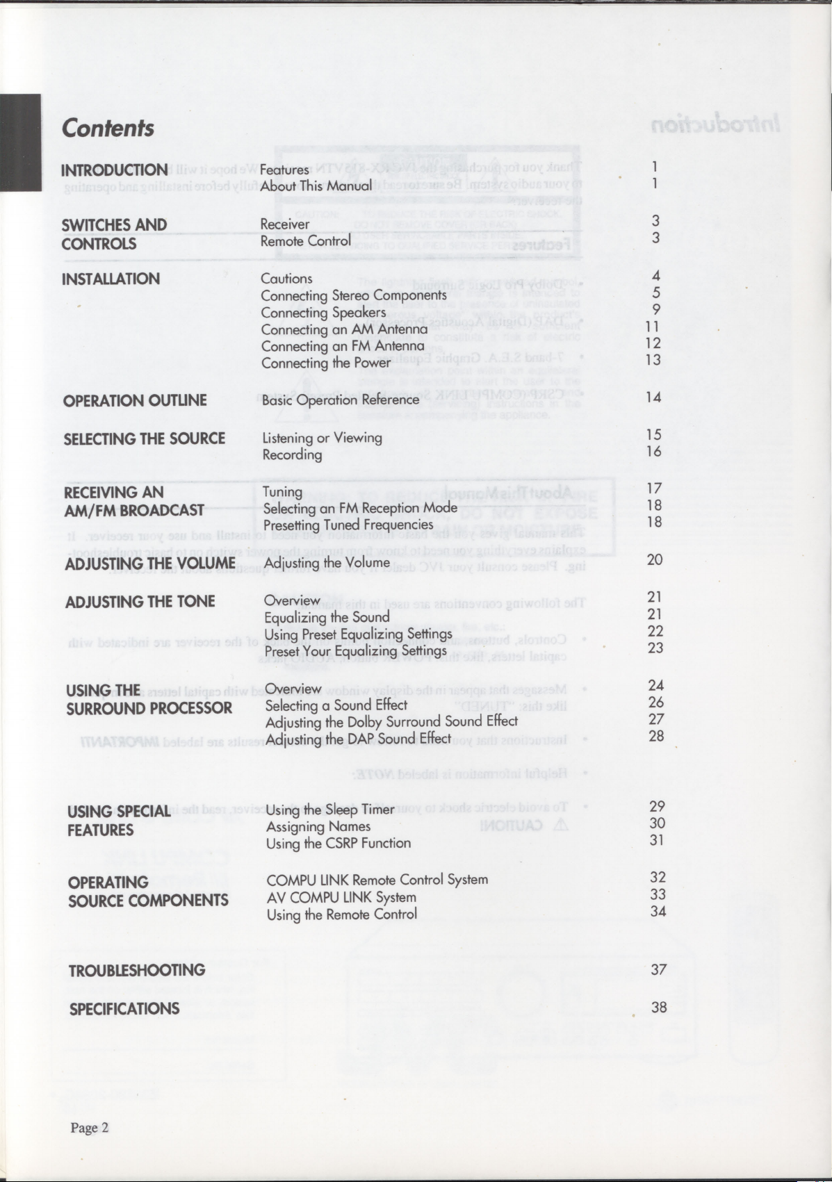
Contents
INTRODUCTION
SWITCHES AND
CONTROLS
INSTALLATION
OPERATION OUTLINE
SELECTING THE SOURCE
RECEIVING AN
AM/FM
BROADCAST
ADJUSTING THE VOLUME
Features
About This Manual
Receiver
Remote Control
Cautions
Connecting Stereo Components
Connecting Speakers
Connecting an AM Antenna
Connecting an FM Antenna
Connecting the Power
Basic Operation Reference
Listening or Viewing
Recording
Tuning
Selecting an FM Reception Mode
Presetting Tuned Frequencies
Adjusting the Volume
3
3
4
5
9
11
12
13
14
15
16
17
18
18
20
ADJUSTING THE TONE
USING THE
SURROUND PROCESSOR
USING SPECIAL
FEATURES
OPERATING
SOURCE COMPONENTS
TROUBLESHOOTING
Overview
Equalizing the Sound
Using Preset Equalizing Settings
Preset Your Equalizing Settings
Overview
Selecting a Sound Effect
Adjusting the Dolby Surround Sound Effect
Adjusting the DAP Sound Effect
Using the Sleep Timer
Assigning Names
Using the CSRP Function
COMPU LINK Remote Control System
AV COMPU LINK System
Using the Remote Control
21
21
22
23
24
26
27
28
29
30
31
32
33
34
37
SPECIFICATIONS
Page 2
38
Page 5
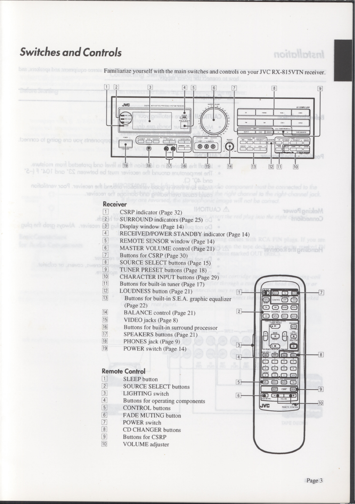
Switches and Controls
Familiarize yourself with the main switches and controls on your J VC RX-815VTN receiver.
CJ
r
Receiver
111
CSRP indicator (Page 32)
[2]
SURROUND indicators (Page 25)
[]
Display window (Page 14)
IT
RECEIVED/POWER STANDBY indicator (Page 14)
37
REMOTE SENSOR window (Page 14)
MASTER VOLUME control (Page 21)
07
Buttons for CSRP (Page 30)
•
SOURCE SELECT buttons (Page 15)
•
TUNER PRESET buttons (Page 18)
N
CHARACTER INPUT buttons (Page 29)
[1j]
Buttons for built-in tuner (Page 17)
M
LOUDNESS button (Page 21)
13
Buttons for built-in S.E.A. graphic equalizer
(Page 22)
•
15
LI
pi
9]
19
Remote Control
[]
I
ai
1111
[]
[j
E]
ai
[]
[
BALANCE control (Page 21)
VIDEO jacks (Page 8)
Buttons for built-in surround processor
SPEAKERS buttons (Page 21)
PHONES jack (Page 9)
POWER switch (Page 14)
SLEEP button
SOURCE SELECT buttons
LIGHTING switch
Buttons for operating components
CONTROL buttons
FADE MUTING button
POWER switch
CD CHANGER buttons
Buttons for CSRP
VOLUME adjuster
L3_1
.<
CL)
(#)
PACS., ,f5/ RECF
L
„. •
t
{
. •
•
001
6(1±1
[ii
re]
' i
7
1 '"*.*..
C11077
I
1
T4 g
f I 1
[IQ]
601
[91
~ii
O O t=i
th O th
Cti-o
L]
Page 3
Page 6
Installation
This section explains how to connect the receiver to other stereo equipment and speakers, and
how to connect the power supply.
Cautions
A
Before Installation
Positioning ihe Receiver
Making Power
Connections
Handling the Receiver
CAUTION!
A
Make sure your hands are dry.
•
Turn
•
Read the installation instructions for all components you are going to connect.
•
CAUTION!
A
Install the receiver in a location that is level and protected from moisture.
•
The temperature around the receiver must be between 23° and 104° F (-5°
•
and 40° C).
Make sure there is good ventilation around the receiver. Poor ventilation
•
could cause overheating and damage the receiver.
CAUTION!
A
Do not handle the power cord with wet hands.
•
Do not pull on the power cord to unplug the receiver. Always grab the plug
•
directly so as not to damage the cord.
CAUTION!
A
Do not insert any metal object into the receiver.
•
Do not disassemble the receiver or remove screws, covers, or cabinet.
•
Do not expose the receiver to rain or moisture.
•
Before installing your receiver:
the power off to all components.
Page 4
Page 7
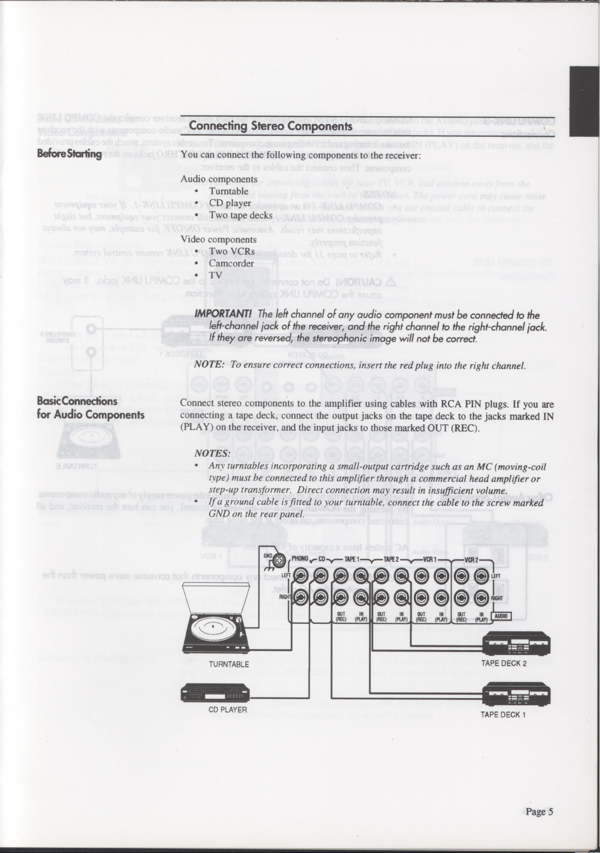
Connecting Stereo Components
BeforeStarting
Basic Connections
for Audio Components
You can connect the following components to the receiver:
Audio components
•
Turntable
•
CD player
•
Two tape decks
Video components
•
Two VCRs
•
Camcorder
•
TV
IMPORTANT!
left-channel jack of the receiver, and the right channel to the right-channel jack.
If they are reversed, the stereophonic image will not be correct.
The left channel of any audio component must be connected to the
NOTE: To ensure correct connections, insert the red plug into the right channel.
Connect stereo components to the amplifier using cables with RCA PIN plugs. If you are
connecting a tape deck, connect the output jacks on the tape deck to the jacks marked IN
(PLAY) on the receiver, and the input jacks to those marked OUT (REC).
NOTES:
•
Any turntables incorporating a small-output cartridge such as an MC (moving-coil
type) must he connected to this amplifier through a commercial head amplifier or
step-up transformer. Direct connection may result in insufficient volume.
•
If a ground cable is fitted to your turntable, connect the cable to the screw marked
CND on the rear panel.
PHONO CO
L,,,zia
RIG T
-y--
TAPE
1-y--
(RU
ae
(p&ln
TAPE
Si
Y
2
()PVT
OUT IN
AUDIO
MS;
TURNTABLE
CD PLAYER
TAPE DECK 2
TAPE DECK 1
Page 5
Page 8
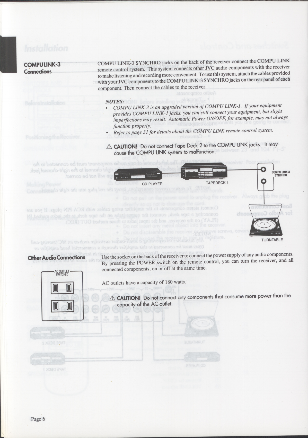
COMPU LINK-3
Connections
COMPU LINK-3 SYNCHRO jacks on the back of the receiver connect the COMPU LINK
remote control system. This system connects other JVC audio components with the receiver
to make listening and recording more convenient. To use this system, attach the cables provided
with your JVC components to the COMPU LINK-3 SYNCHRO jacks on the rear panel of each
component. Then connect the cables to the receiver.
NOTES:
COMPU LINK-3 is an upgraded version of COMPU LINK-1. If your equipment
•
provides COMPU LINK-1 jacks, you can still connect your equipment, but slight
imperfections may result. Automatic Power ON/OFF, for example, may not always
function properly.
Refer to page 31 for details about the COMPU LINK remote control system.
•
Other Audio Connections
SWITCHED
CAUTION!
A
Do not connect Tape Deck 2 to the COMPU LINK jacks. It may
cause the COMPU LINK system to malfunction.
0
1-
imimaaam
CD PLAYER
Use the socket on the back of the receiver to connect the power supply of any audio components.
TAPEDECK 1
COMPU LINK-3
SYNCHRO
TURNTABLE
By pressing the POWER switch on the remote control, you can turn the receiver, and all
connected components, on or off at the same time.
AC outlets have a capacity of 180 watts.
Page 6
CAUTION!
Do not connect any components that consume more power than the
capacity of the AC outlet.
Page 9
Basic Connections for
Video Components
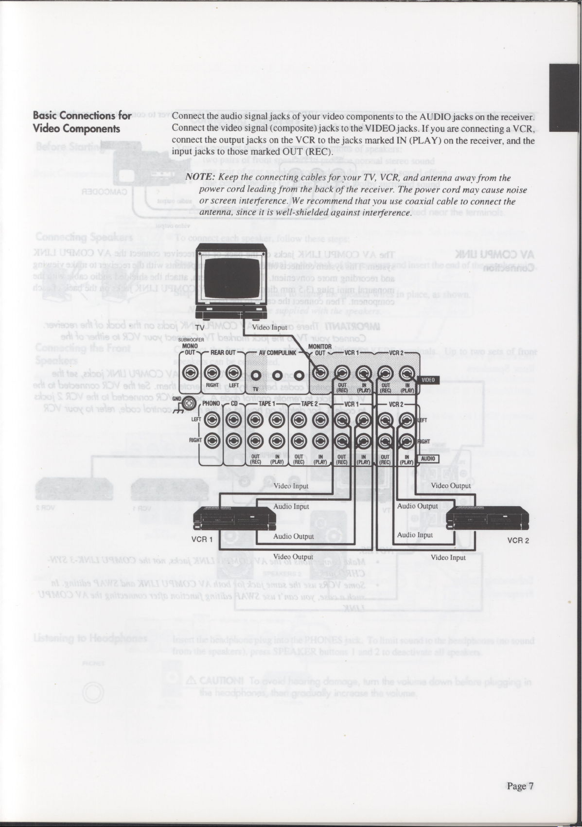
Connect the audio signal jacks of your video components to the AUDIO jacks on the receiver.
Connect the video signal (composite) jacks to the VIDEO jacks. If you are connecting a VCR,
connect the output jacks on the VCR to the jacks marked IN (PLAY) on the receiver, and the
input jacks to those marked OUT (REC).
NOTE: Keep the connecting cables for your TV, VCR, and antenna away,
power cord leading from the back of the receiver. The power cord may cause noise
or screen interference. We recommend that you use coaxial cable to connect the
antenna, since it is well-shielded against interference.
TV
SUBWOOFER
MONO
t" OUT
-se—
O
GND
( PRONG v.— CD
LEFT 0
RIGHT C) O
REAR OUT me-
Se
RIGHT LEFT
Video Input
-
AV COMPULINK OUT
MONITOR
0 0 0
(REC) (KM (REP
TAPE 1 --y
—
TAPE 2
8888880SO
880®688@
OUT IN
(REC)
(PLAY)
OUT IN
(REC) (PLAY)
A
(REC) (PLAY)
VCR 1
OUT IN
VCR 1
OUT IN
VCR 2
OUT
(REC)
VCR 2
(PLAY)
VIDEO
FT
GHT
IN
AUDIO
from the
VCR 1
Video Input
Audio Input
Audio Output
Video Output
Audio Output
Audio Input
Video Output
VCR 2
Video Input
Page 7
Page 10
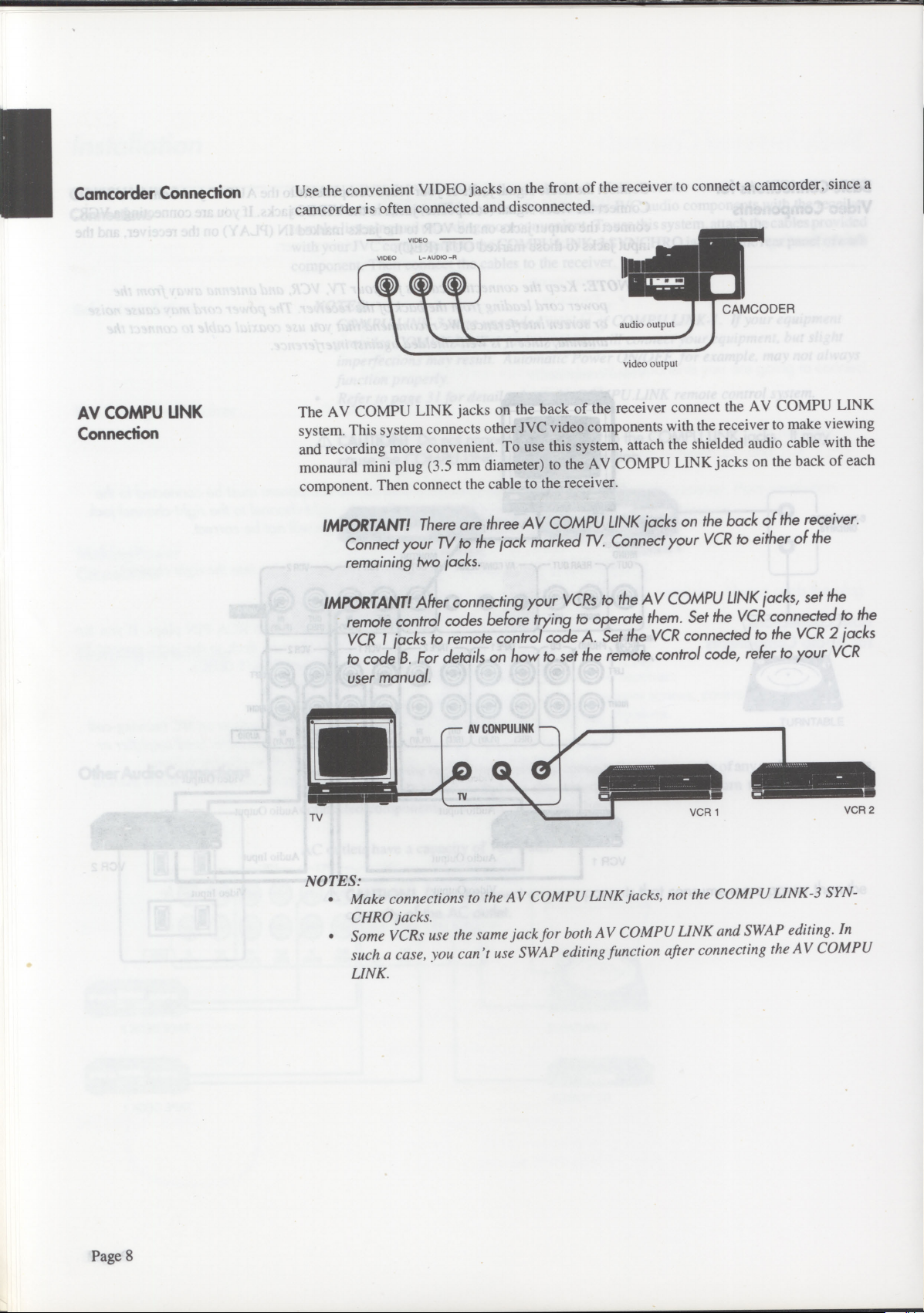
Camcorder Connection
Use the convenient VIDEO jacks on the front of the receiver to connect a camcorder, since a
camcorder is often connected and disconnected.
VIDEO
L- AUDIO -R
VIDEO
II
AV COMPU UNK
Connection
audio output
video output
The AV COMPU LINK jacks on the back of the receiver connect the AV COMPU LINK
system. This system connects other JVC video components with the receiver to make viewing
and recording more convenient. To use this system, attach the shielded audio cable with the
monaural mini plug (3.5 mm diameter) to the AV COMPU LINK jacks on the back of each
component. Then connect the cable to the receiver.
CAMCODER
are three AV COMPU LINK jacks on the back of the receiver.
IMPORTANT!
There
Connect your TV to the jack marked TV. Connect your VCR to either of the
remaining two jacks.
IMPORTANT!
After connecting your VCRs to the AV COMPU LINK jacks, set the
remote control codes before trying to operate them. Set the VCR connected to the
VCR I jacks to remote control code A. Set the VCR connected to the VCR 2 jacks
For details on how to set the remote control code, refer to your VCR
to code
B.
user manual.
A
AV CONPULINK
11.11.41
TV
-A
nt
VCR 1
NOTES:
Make connections to the AV COMPU LINK jacks, not the COMPU LINK-3 SYN-
•
CHRO jacks.
Some VCRs use the same jack for both AV COMPU LINK and SWAP editing. In
•
such a case, you can't use SWAP editing function after connecting the AV COMPU
LINK.
VCR 2
Page 8
Page 11
Connecting Speakers
Before Starting
Connecting Speakers
Connecting the Front
Speakers
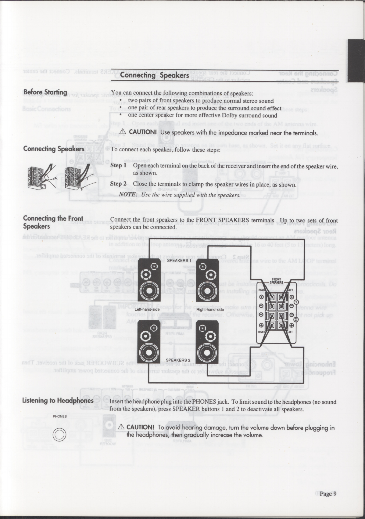
You can connect the following combinations of speakers:
•
two pairs of front speakers to produce normal stereo sound
•
one pair of rear speakers to produce the surround sound effect
•
one center speaker for more effective Dolby surround sound
A
CAUTION!
To connect each speaker, follow these steps:
Step 1 Open each terminal on the back of the receiver and insert the end of the speaker wire,
as shown.
Step 2 Close the terminals to clamp the speaker wires in place, as shown.
NOTE: Use the wire supplied with the speakers.
Connect the front speakers to the FRONT SPEAKERS terminals. Up to two sets of front
speakers can be connected.
Use speakers with the impedance marked near the terminals.
SPEAKERS 1
Listening to Headphones
PHONES
0
Left-hand-side
SPEAKERS 2
Insert the headphone plug into the PHONES jack. To limit sound to the headphones (no sound
from the speakers), press SPEAKER buttons 1 and 2 to deactivate all speakers.
A
CAUTION!
the headphones, then gradually increase the volume.
To avoid hearing damage, turn the volume down before plugging in
Right-hand-side
Page 9
Page 12
Connecting the Rear
Speakers and Center
Speakers
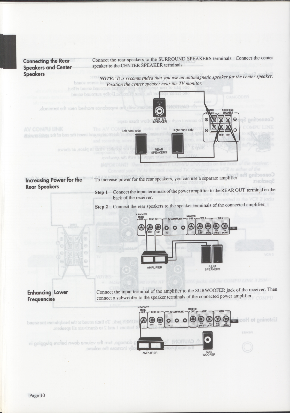
Connect the rear speakers to the SURROUND SPEAKERS terminals. Connect the center
speaker to the CENTER SPEAKER terminals.
NOTE: It is recommended that you use an antimagnetic speaker for the center speaker.
Position the center speaker near the TV monitor.
SURROUND
TER
SPEAKERS
CENTER
SPEAKER
Increasing Power for the
Rear Speakers
Left-hand side
REAR
SPEAKERS
To increase power for the rear speakers, you can use a separate amplifier.
Right-hand-side
Step 1 Connect the input terminals of the power amplifier to the REAR OUT terminal on the
back of the receiver.
Step 2 Connect the rear speakers to the speaker terminals of the connected amplifier.
SUBWOOFER
MONO
B OUT1 REAR OUT —.. .e-- AV COMPULMK —%, OUT se—VCR 1
0 0 0
AMPLIFIER
R
MONITO
soose
REAR
SPEAKERS
VCR 2 --...
VIDEO
Enhancing Lower
Frequencies
Page 10
Connect the input terminal of the amplifier to the SUB WOOFER jack of the receiver. Then
connect a subwoofer to the speaker terminals of the connected power amplifier.
SUBWOOF R
MONO
OUT .r REAR OUT —,e
i
0 8
RIGHT LEFT
LA.!
AMPLIFIER
• AV COMPULINK --•••• OUT
"
-
.
0 0 0
MONITOR
e..•••VCR 1 -.-"s..eVCR 2-'
N
O
0 C
OUT
t
III
(PLAN
lit
SUB
WOOFER
8 0
OW
IMP INV)
.
DEO
IR
Page 13
Connecting an AM Antenna
Before Starting
Basic Connections
AM Outdoor Antenna
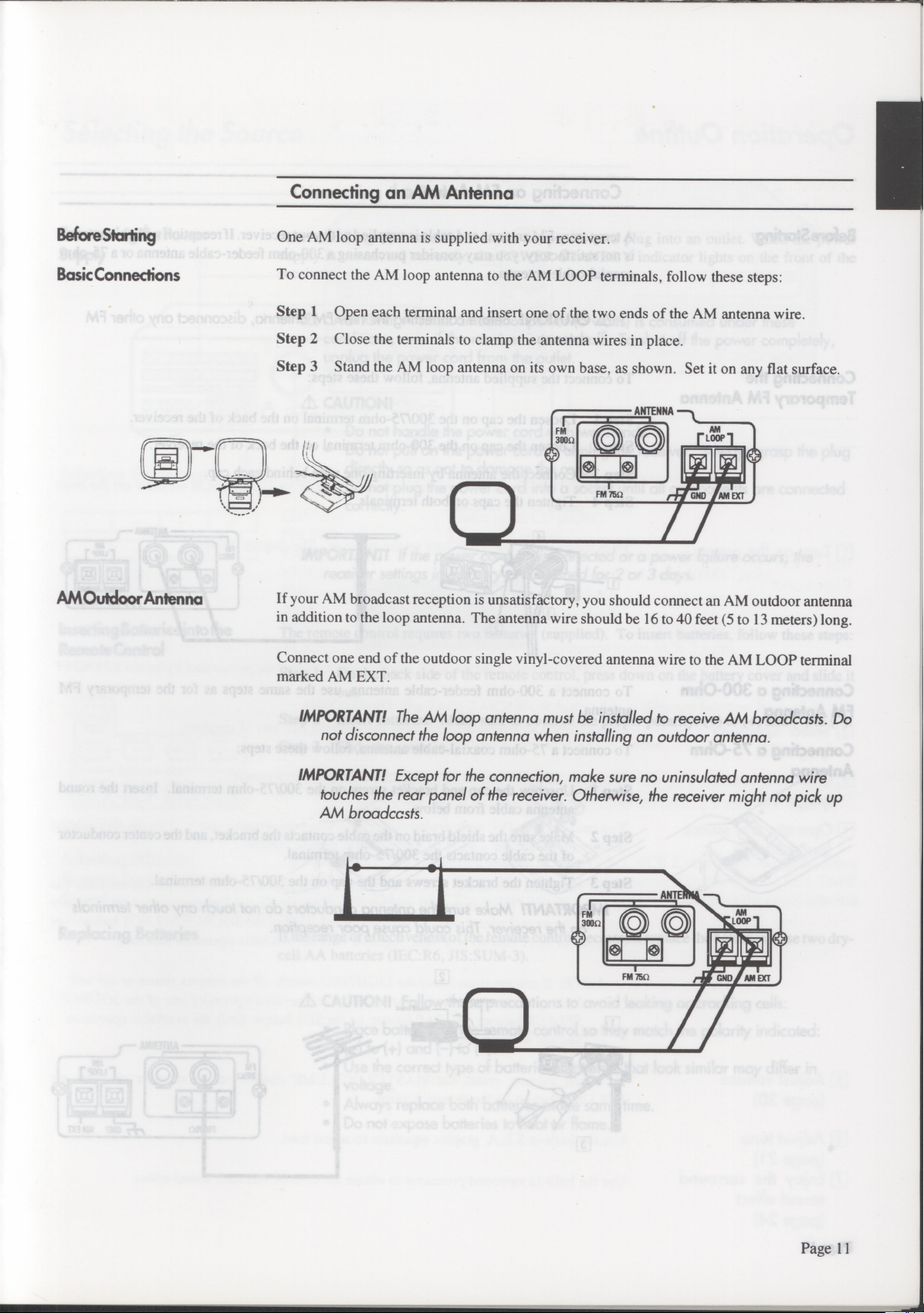
One AM loop antenna is supplied with your receiver.
To connect the AM loop antenna to the AM LOOP terminals, follow these steps:
Step 1 Open each terminal and insert one of the two ends of the AM antenna wire.
Step 2 Close the terminals to clamp the antenna wires in place.
Step 3 Stand the AM loop antenna on its own base, as shown. Set it on any flat surface.
If your AM broadcast reception is unsatisfactory, you should connect an AM outdoor antenna
in addition to the loop antenna. The antenna wire should be 16 to 40 feet (5 to 13 meters) long.
Connect one end of the outdoor single vinyl-covered antenna wire to the AM LOOP terminal
marked AM EXT.
IMPORTANT!
not disconnect the loop antenna when installing an outdoor antenna.
IMPORTANT!
touches the rear panel of the receiver. Otherwise, the receiver might not pick up
AM broadccsts.
The AM loop antenna must be installed to receive
Except for the connection, make sure no uninsulated antenna wire
AM
broadcasts. Do
Page 11
Page 14
Connecting an FM Antenna
Before Starting
Connecting the
Temporary FM Antenna
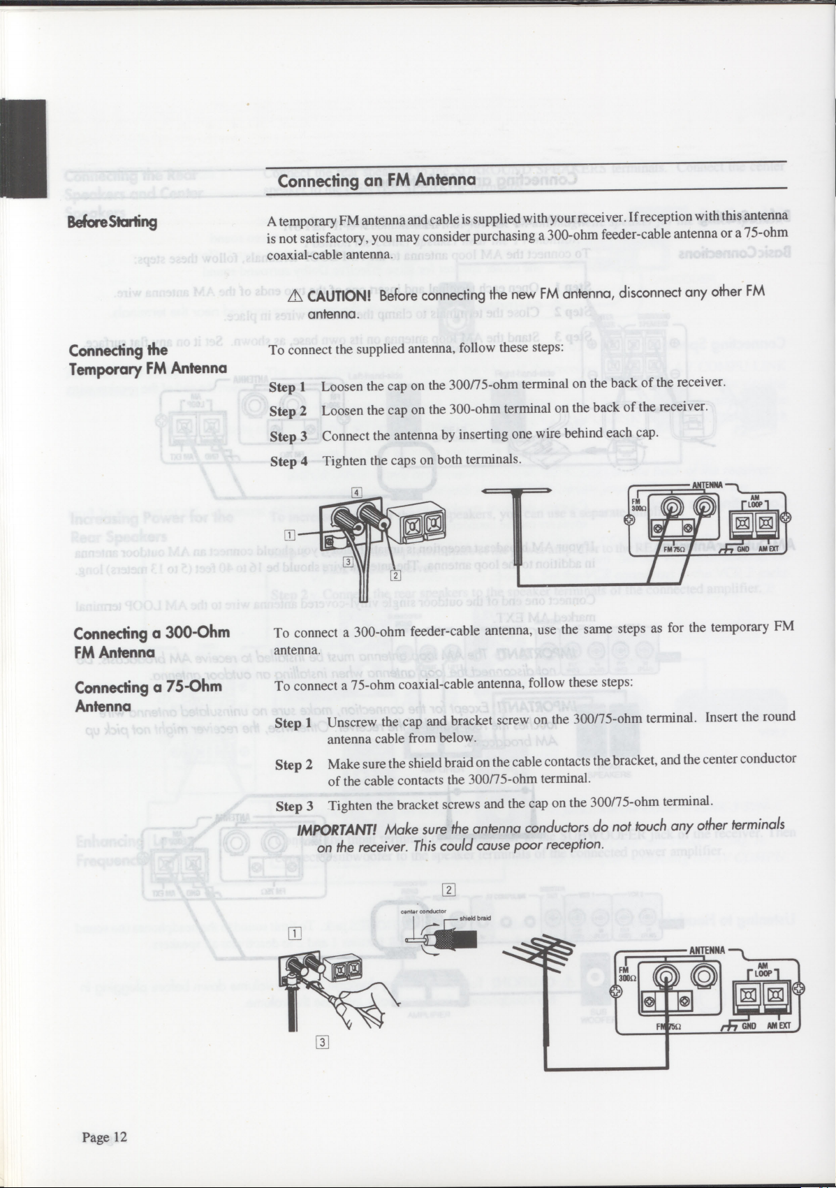
A temporary FM antenna and cable is supplied with your receiver. If reception with this antenna
is not satisfactory, you may consider purchasing a 300-ohm feeder-cable antenna or a 75-ohm
coaxial-cable antenna.
A\ CAUTION!
antenna.
Before connecting the new FM antenna, disconnect any other FM
To connect the supplied antenna, follow these steps:
Step 1
Step 2
Step 3
Step 4
Loosen the cap on the 300/75-ohm terminal on the back of the receiver.
Loosen the cap on the 300-ohm terminal on the back of the receiver.
Connect the antenna by inserting one wire behind each cap.
Tighten the caps on both terminals.
Connecting a 300-Ohm
FM Antenna
Connecting a 75-Ohm
Antenna
To connect a 300-ohm feeder-cable antenna, use the same steps as for the temporary FM
antenna.
To connect a 75-ohm coaxial-cable antenna, follow these steps:
Step 1
Unscrew the cap and bracket screw on the 300/75-ohm terminal. Insert the round
antenna cable from below.
Step 2
Make sure the shield braid on the cable contacts the bracket, and the center conductor
of the cable contacts the 300/75-ohm terminal.
Step 3
Tighten the bracket screws and the cap on the 300/75-ohm terminal.
IMPORTANT!
on the receiver. This could cause poor reception.
Make sure the antenna conductors do not touch any other terminals
center conductor
Page 12
Page 15

Connecting the Power
Connecting the Power
Supply
Inserting Batteries into the
Remote Control
After checking all connections, insert the power cord plug into an outlet. When the power
supply is connected correctly, the POWER STANDBY indicator lights on the front of the
receiver.
A
CAUTION!
conditions, even if the receiver is turned off. To shut off the power completely,
unplug the power cord from the outlet.
A
CAUTION!
•
Do not handle the power cord with wet hands.
•
Do not pull on the power cord to unplug the receiver. Always grasp the plug
directly so as not to damage the cord.
•
Do not plug the power cord into a socket until all components are connected
correctly.
IMPORTANT!
receiver settings in memory are retained for 2
The remote control requires two batteries (supplied). To insert batteries, follow these steps:
Step 1 On the back side of the remote control, press down on the battery cover and slide it
out.
A small amount of power
If the power cord is disconnected or a power failure occurs, the
(5 watts)
is consumed under these
or
3 days.
Replacing Batteries
Step 2 Insert batteries. Make sure to observe the proper polarity: (+) to (+) and (—) to (—).
Step 3 Slide the cover in.
If the range or effectiveness of the remote control decreases, replace the batteries. Use two dry-
cell AA batteries (IEC:R6, JIS:SUM-3).
A
CAUTION!
•
Place batteries in the remote control so they match the polarity indicated:
(+) to (+) and (-) to (-).
•
Use the correct type of batteries. Batteries that look similar may differ in
voltage.
•
Always replace both batteries at the same time.
•
Do not expose batteries tc heat or flame.
Follow these precautions to avoid leaking or cracking cells:
Page 13
Page 16

Operation Outline
Basic Operation Reference
['Turn
['Select
on the power
speakers
(page 21)
['Choose a source
(page 15)
El Operate the source
(page 34-36)
IMPORTANT! Aim
panel of the receiver.
Push the POWER switch to turn on the receiver. The display lights:
NOTE:
Use the SPEAKERS switch to choose between the two sets of speakers.
Press one of the SOURCE SELECT buttons to choose a source.
You can operate a JVC audio/video component using the remote control. You can also operate
another manufacturer's VCR or TV using the remote control.
When you press one of the SOURCE SELECT buttons or CONTROL section buttons, the
remote control of that component will become available.To confirm the component currently
selected, press and release the LIGHTING switch. One of the SOURCE SELECT buttons (or
the DAP or SEA button) will light, together with the available operation buttons.)
Pushing the POWER switch again turns off the power and lights the STANDBY
light.
the remote control at the
p
ri
REMOTE SENSOR
window on the front
Adjust volume
(page 20)
El Adjust tone
(page 21)
11] Enjoy the surround
sound effect
(page 24)
Page 14
NOTE:
To adjust volume, rotate the MASTER VOLUME control on the receiver or press the
VOLUME button on the remote control.
Use the built-in S.E.A. graphic equalizer to adjust tone.
Use the built-in surround processor to obtain the desired surround sound effect.
If you press and hold the LIGHTING switch, all the buttons shown at left will
light up. Select the component you want to operate by pressing one of the SOURCE
SELECT buttons, the DAP button, or the SEA button. Only the available operation
buttons will remain lit.
Page 17

Selecting the Source
Listening or Viewing
Selecting the Source
AU
0 0
SOURCE SELECT
Selecting Different
Sources for Picture and
Sound
Press one of the SOURCE buttons on the receiver or the remote control.
CD*
PHONO*
TAPE 1*
VIDEO
FM*
AM*
VCR1
VCR2
TAPE 2 MONITOR
IMPORTANT!
source selector buttons, because it allows you to monitor the quality of the
recording. For more details, see Monitoring below.
* NOTE: On the remote, when you press one of the SOURCE buttons marked above
with an asterisk, the receiver automatically turns ON (even if it was OFF before).
To listen to another audio source while watching VCR 1, VCR 2, or VIDEO, first press either
the VCR 1 or VCR 2 button. Then select one of the audio sources: CD, PHONO, TAPE 1, TAPE
2 MONITOR, FM, or AM. The picture will be combined with sound from the newly selected
audio source.
The TAPE 2 MONITOR button has a different function from other
Listen to the CD player.
Listen to a record.
Listen to the tape deck connected to the TAPE 1 jacks.
View the camcorder connected to the VIDEO jacks.
Listen to an FM broadcast.
Listen to an AM broadcast.
View the VCR connected to the VCR 1 jacks.
View the VCR connected to the VCR 2 jacks.
Listen to the tape deck connected to the TAPE 2 jacks.
'age 14
Error
You can operate a JVC audio/video component using the
remote control. You can also operate another manufacturer's
VCR or TV using the remote control.
Correction
You can operate a JVC audio/video component using the
remote control. You
VCR
or TV irsiirg the-icmotc control.
can also operateanother m
Page 15
Page 18

Recording
The source being played is automatically selected as the source to be recorded. While
recording, you can listen to the selected source at any desired volume and tone settings.
NOTE: Volume and Tone adjustments and the surround sound effect do not affect
recording.
Monitoring
IMPORTANT!
MONITOR button and another button other than
Using the Monitor feature, you can compare the sound quality of the source to the sound quality
of the recording being made.
To use the Monitor feature while recording onto a cassette deck connected to the TAPE 2 jacks,
follow these steps:
Step 1
Step 2
Press the TAPE 2 MONITOR button.
The "TAPE 2 MONITOR" light appears and you can listen to the sound of the cassette
deck connected to the TAPE 2 jacks. You are now hearing the quality of the recording,
not the quality of the source.
Press the TAPE 2 MONITOR button again.
This turns off the "TAPE 2 MONITOR" light, and the speakers play the previously
selected source.
NOTE: If the cassette deck has three heads, you can hear the sound of the recording at
the same time as it records on the tape.
When recording from
TAPE 2
to
TAPE
1.
1, press the
TAPE
TAPE 2
Page 16
Page 19

Receiving an AM/FM Broadcast
To receive an AM/FM broadcast, select either AM or FM using the AM button or FM button.
Then tune to the precise frequency using the FREQUENCY buttons.
Tuning
FREQUENCY
Manual Tuning
AutomaticTuning
Tune to the frequency of a desired station using the FREQUENCY buttons. Pressing the right
button increases the frequency, and pressing the left button decreases the frequency. Tapping
the FREQUENCY button once changes the frequency in steps of 10 kHz for AM and 0.1 MHz
for FM.
There are two tuning modes: Manual and Automatic.
If you know the frequency of a desired station, hold down the FREQUENCY button to start the
frequency changing quickly. Release the FREQUENCY button near the desired station and tap
it repeatedly until you arrive at the correct frequency.
If you want to scan frequencies for a desired station, hold down the FREQUENCY button to
start the frequency changing quickly. When you release the FREQUENCY button, the
frequency continues to change until it reaches a station.
When a station is correctly tuned, the "TUNED" light appears on the display window.
Once a tuned frequency is preset, it can be directly recalled using the TUNER buttons. For
details, see pages 18-19.
NOTE: When you use automatic tuning, weak stations are ignored. To pick up weak
stations, use manual tuning.
IMPORTANT!
appear, try rotating the antenna for better reception.
If the receiver is tuned to a station but the 'TUNED" light does not
Page 17
Page 20

Selecting an FM Reception Mode
FM MODE
MUTE
Automatic Mode
Monaural Mode
Entering Channel
Numbers
- TUNER PRESET-
Pressing the FM MODE/MUTE switch switches between these modes.
The "MUTE-AUTO" light appears in the display window. You hear either stereo sound or
monaural sound, depending on the broadcast. If it is a stereo broadcast, the "STEREO" light
appears. This mode is also useful for suppressing static "noise" between stations.
The "MUTE-AUTO" light disappears. You hear monaural sound even if a broadcast is in
stereo. This mode is also useful when a stereo broadcast is noisy because of a weak signal.
NOTE: Using the Automatic Tuning mode, the sound of a broadcast with a weak signal
may be muted. In this case, select the monaural mode.
Presetting Tuned Frequencies
You can preset up to 40 radio stations by assigning channel numbers (1 through 40) to them.
Once a station is preset, you can listen to it by entering the preset number. There are two ways
to preset: manual or automatic.
To select numbers, use the TUNER PRESET buttons.
Press > (+ on the remote) to increase the selected number, and press < (- on the remote) to lower
the selected number.
+10
Manual Presetting
MEMORY
To select numbers from 11 through 40, using the +10 button is more convenient. Each time you
press the +10 button, the number will increase by a multiple of 10. Then press a number less
than 10 to complete the desired number.
IMPORTANT!
the AM or FM button on the remote.
To use manual presetting to assign channel numbers to your favorite stations, follow these steps:
Step 1 Tune to a station. If necessary, follow the procedure on page 17.
Step 2 Press the MEMORY button.
The "MEMORY" light appears in the display window.
Step 3 Using the TUNER PRESET buttons, select a number (1 through 40), then press the
MEMORY button to enter the selected number. This channel number is automatically
assigned to the station.
IMPORTANT!
You have about
channel number, press the MEMORY button again.
Step 4 When the MEMORY light disappears and the channel number is displayed, presetting
is completed.
Before you use the PRESET CHANNEL buttons on the remote, press
You must enter the channel number while the "MEMORY" light is on.
seconds to do this. If the light disappears before you enter the
5
Page 18
Page 21

Automatic Presetting
To use automatic presetting to preset up to 40 stations automatically, follow these steps:
AUTO MEMORY
Step 1
Step 2
Press the SOURCE selector button to select AM or FM.
Using the FREQUENCY buttons, move to the lowest frequency from which you want
scanning to begin.
Step
3 Press the AUTO MEMORY button.
The "AUTO MEMORY" light appears in the display window.
Step 4
Using the TUNER PRESET buttons, select a channel number (1 through 40) to the
first tuned station, then press the AUTO MEMORY button to enter the selected
number. From that point, scanning starts and stations are assigned channel numbers
in ascending order.
IMPORTANT!
You must enter the channel number while the "AUTO MEMORY" light
appears. If this light disappears before you enter the channel number, press the
AUTO MEMORY button again.
Frequencies are scanned in ascending order. When a station is tuned in, scanning stops and the
"TUNED" light and preset number appear. The station is preset about 4 seconds later and the
"MEMORY" light appears. If you do not want to preset this station, press the AUTO
MEMORY button within 4 seconds. Scanning restarts without presetting that station.
When the MEMORY light disappears, scanning continues until one of the following occurs:
•
Another station is tuned in
•
The upper limit of the tuning range is reached
•
All 40 channel numbers have been assigned
Recalling a Preset
Channel
When Auto Presetting is completed, the last preset station is received.
NOTE:
To stop scanning at any time, press any TUNER button once.
You can recall a preset channel using the TUNER PRESET buttons (see page 18).
You can also recall a preset channel by specifying the number directly, using the remote control.
First press the AM or FM button on the remote, then enter the channel number using 1-10, and
the +10 button. To choose numbers from 1 through 10, press the appropriate buttons. To choose
numbers from 11 through 40, press the +10 button and one other button. For example:
To choose 17 Press +10, then 7.
To choose 20
To choose 25
To choose 40
Press +10, then 10.
Press +10 twice, then 5.
Press +10 three times, then 10.
Your channel number will appear.
NOTE:
You can assign a title of up to five characters (for example, a station name) to
each preset station (1-10). See page 31 for further details.
Page 19
Page 22

Adjusting the Volume
Adjusting the Volume
"M!!!s
•
'-
117E7.
7
TZZ1
4:,
Using the MASTER
VOLUME Control
Muting the Sound
Selecting the Speakers
I SPEAKERS
00
2
- ON I OFF
Use the MASTER VOLUME control to adjust the volume from the left and right speakers.
Rotating the dial to the right increases the volume. The volume from the speakers and the
headphones increases simultaneously.
NOTE: Volume can also be adjusted using the remote control. Press the VOLUME
button marked + to increase the volume, or the VOLUME button marked — to
decrease the volume.
,A CAUTION!
Listening to extremely loud sound may damage your hearing. Be
especially careful when using headphones.
Press the FADE MUTING button on the remote control to decrease the volume easily when you
receive a phone call or a visitor.
NOTE: When vou press the FADE MUTING button again, the previous volume setting
will return.
Pushing in SPEAKER button 1 or 2 activates that pair of speakers. Pressing either button again
deactivates that pair of speakers. When the button is in, that pair is activated. You can listen
to both pairs, pair 1, pair 2, or neither pair.
IMPORTANT!
If only one
set of speakers is connected, pressing "in" both speaker
buttons will produce no sound.
Listening at Low Volume
LOUDNESS
)
Adjusting the Left-Right
Balance
BALANCE
CENTER
0
LEFT 10
Page 20
RIGHT
Human ears are not sensitive to low-frequency sounds at low volume. To compensate for this,
the loudness function automatically boosts the bass level as you lower the volume.
To use the loudness function, press the LOUDNESS switch. The "LOUDNESS" indicator
lights in the display window. Press the switch again to turn the feature off.
Use the BALANCE control to adjust the balance between the left and right channels. Rotating
the dial to the right increases the right-channel volume, and rotating it to the left increases the
left-channel volume. The BALANCE control affects both sets of speakers and the headphones.
Page 23

Adjusting the Tone
SEA
Overview
Using the S.E.A. Graphic Equalizer, you can change the tone as you desire.
Pressing the SEA button on the receiver activates the S.E.A. Graphic Equalizer. The Graphic
Equalizer divides the audible frequency range into seven bands. You can adjust the boost/cut
level of each band to get the desired sound.
o o
Equalizing
6
FREQUENCY ›-
LEVEL
IMPORTANT!
channel sound.
NOTE: You can also operate the S.E.A. Graphic Equalizer with the remote control.
Press the SEA button in the CONTROL section of the remote, then the ON/OFF
button on the remote. Then press the desired button. The orange lettering on the
remote control shows how to operate the S.E.A. graphic equalizer.
Equalizing the Sound
To equalize the sound, follow these steps:
Step 1 Select a frequency range to be adjusted using the FREQUENCY buttons.
Center frequencies of available frequency ranges are: 63 Hz, 160 Hz, 400 Hz, 1 kHz,
2.5 kHz, 6.3 kHz, and 16 kHz. Pressing the right button switches to a higher frequency
range, and pressing the left button switches to a lower frequency range.
Step 2 Set the boosting or cutting level for the selected frequency range using the LEVEL
buttons.
The S.E.A. Graphic Equalizer has no effect on rear and center
Pressing the right button boosts the range and pressing the left button cuts the range.
You can boost or cut the range in 2 dB units within the range of 10dB.
s,r,
Page 21
Page 24

Hints for Equalizing
The following hints will help you to use the graphic equalizer more effectively.
FLAT
SEA
)
Selecting a Preset
Equalizing Setting
PRESET
i
To reset and begin equalizing again, press the FLAT button.
To compare the sound processed by the S.E.A. graphic equalizer with the original sound during
equalizing, press the SEA button on the receiver or the ON/OFF button on the remote. Pressing
either button allows you to hear the equalized sound again.
The following illustration shows the relatiorthhips between frequency range and the effect of
boosting/cutting. Refer to it when equalizing the sound.
Si engage:
Si coupe:
lourd large aigu fwid
leger diminulif doux chaleureux
Using Preset Equalizing Settings
You can select any one of ten preset equalizing settings.
Press the PRESET button to select one of the preset equalizing settings.
Letters A to J are assigned to preset equalizing settings. Letters A to E are assigned to user-preset
settings, which you can preset to your desired equalizing settings. Letters F to J are factory-
preset settings. Typical equalizing settings are preset in the factory as follows, with titles that
describe their characteristics. You cannot modify these settings.
A-E
User-preset equalizing.
F - "HEAVY" Select this setting when you want heavy sound. Both high and low frequen-
cies are boosted.
G - "CLEAR" Select this setting when you want clear sound. Frequencies which make the
sound unclear are cut.
H -
"SOFT"
Select this setting when you listen to background music at a low sound level.
Rasping sound is suppressed and low frequencies are boosted.
I - "MOVIE"
Select this setting when you listen to the sound track of an old movie. The
sound in the narrow frequency range can be equalized.
Select this setting to bring the singer's voice forward. The presence of the
J - "VOCAL"
human voice increases.
Page 22
Page 25

Preset Your Equalizing Settings
You can preset up to five equalizing settings of the S.E.A. graphic equalizer. Each equalizing
setting is assigned a letter (A to E). Once an equalizing setting has been preset, you can call it
directly using the PRESET button.
To preset your own equalizing settings, follow these steps:
SEA
(
-c FREQUENCY >.
MEMORY
PRESET
LEVEL
Step 1
Press the SEA button to operate the S.E.A. graphic equalizer.
The SEA light appears on the display.
Step 2
Step 3
Using the FREQUENCY and LEVEL buttons, adjust the tone as desired.
Press the MEMORY button.
The MEMORY light blinks.
Step 4
Press the PRESET button to select the letter to be assigned to your equalizing setting.
Pressing the PRESET button repeatedly selects letters in the following order:
A>B>C>D>E> back to the beginning
Step 5
Press the MEMORY button again.
The MEMORY light goes off to indicate that presetting for your equalizing setting has
been completed.
NOTE: You can assign a title with five or fewer characters to each preset equalizing
setting. When a preset equalizing setting is called, its title appears in the display
window along with its assigned letter. See page 31.
Page 23
Page 26

Using the Surround Processor
7±7 0o
The built-in surround processor enables you to enjoy a 3-dimensional sound effect.
Overview
--"
W01
i
Turning on the Effect
Types of Sound Effects
Pressing the PROCESSOR button on the receiver activates the surround processor. You can
experiment with a variety of sources and surround sound effects.
NOTE:
You can also operate the surround processor with the remote control. Press the
PROCESSOR button in the upper CONTROL section of the remote, then the
PROCESSOR ON/OFF button on the remote. Then press the desired operation
buttons. The blue lettering on the remote control shows how to operate the surround
processor.
The surround processor provides two groups of programs for a total of 6 sound effects.
Dolby surround sound effects group:
Dolby Pro Logic Surround and Dolby 3-Channel Logic.
These programs replicate the sound experienced in a movie theater. For best results, Dolby Pro
Logic Surround requires one center speaker and two rear speakers, in addition to the front
speakers. Dolby 3-Channel Logic requires one center speaker in addition to the front speakers.
JVC's DAP (Digital Acoustics Processor) sound effect group: HALL, PAVILION,
STADIUM, and LIVECLUB. These programs reproduce the acoustics of a concert venue.
Each program in this group requires two rear speakers in addition to the front speakers.
Page 24
front speakers
MI
••••—,
center speakers
Ell rear speakers ill
Dolby Pro Logic Surround
r front speakers
111 .M. 11.1
v..,=,
,---, ...—, ,---,
..........."
Dolby 3-Channel Logic
center speakers
ss
.......
.........."
front speakers
MI rear speakers 1
11
DAP
-'
Page 27

What is Dolby Pro Logic
Surround?
What is DAP Sound
Effect?
The soundtracks of video software bearing the
[ELM" SUMUND
mark* include the same
encoded surround information as that found in Dolby Stereo films. The Dolby Pro Logic
Surround decoder is a consumer version of the decoding process used in professional Dolby
Stereo equipment, and it lets you recreate the theater ambience and effects of Dolby Stereo at
home.
Dolby Pro Logic Surround decoder provides these features:
•
four primary sound channels — Left, Right, Surround, and additional Center channel
•
adaptive matrix to actively derive each channel
The result is that Dolby Pro Logic Surround has the effect of widening the useful listening area
and enhancing directional effects, while at the same time locking center channel information
onscreen for the home audience.
* Manufactured under license from Dolby Laboratories Licensing Corporation. Additionally licensed under one
or more ofthe following patents: U.S. number 3.959,590: Canadian numbers 1,004.603 and 1,037,877. "Dolby",
"Pro Logic", and the double-D symbol are trademarks of Dolby Laboratories Licensing Corporation.
The sound we hear at a concert can be classified into the following three components:
•
Direct sound - Sound directly reaching the ears from the source.
•
Early reflections - Sound reaching the ears after several reflections from walls and
ceiling.
•
Reverberations - Sound reaching the ears after many reflections.
A combination of direct sound, early reflections, and reverberations give each individual
concert venue unique acoustic characteristics.
JVC measured and analysed famous concert venues around the world using JVC's advanced
measurement system. Four sets of this acoustic data are stored in the DAP. DAP creates early
reflections and reverberations based on the stored acoustics data and adds them to the source
sound to simulate the acoustics of a specific venue.
Page 25
Page 28

Selecting a Program
Selecting a Sound Effect
The surround processor provides six types of sound effects.
MODE
Selecting a Center
Channel Mode
"PRO LOGIC" To play a source marked DO
"3CH LOGIC" To play a source marked DO
DOLBY SURROUND
DOLBY SURROUND
when you are not using rear
speakers.
"DIGITAL AP" To play an ordinary stereo source with JVC's DAP sound effect. This brings
you the effect of a live performance, as in a concert hall. The venues which
can be simulated are as follows:
"HALL"
A shoe-box type hall accommodating an audience of 2,200
in the Netherlands.
"PAVILION" An octagonal pavilion with a high ceiling in Japan.
"STADIUM" A stadium accommodating about 30,000 people.
"LIVECLUB" A live music club with a low ceiling in Japan.
To select one of these programs, use the MODE button. The program changes each time you
press the button. The program name will be shown by the combination of the SURROUND
indicator and the message in the display window (shown in quotes) in the following cycle:
PRO LOGIC "DOLBY" > 3CH LOGIC "DOLBY" > DIGITAL AP "HALL" > "PAVIL" >
"STDUM" > "LIVE" > begins the cycle again
When you select the PRO LOGIC or 3CH LOGIC programs, you must also select a center
channel mode. The following modes are available:
CENTER MODE TEST
Page 26
"PHANTOM" Use this mode when no center speaker is used. The entire center channel is
reproduced through the front speakers. 3CH LOGIC doesn't have this mode.
"NORMAL"
Use this mode when the center speaker is smaller than the front speaker. The
bass frequencies in the center channel are reproduced through the front
speakers.
"WIDE"
Use this mode when the center speaker is as large as the front speaker. The
entire center channel is reproduced through the center speaker.
"OFF'
The center channel is muted.
To select one of these modes, use the CENTER MODE button on the receiver. Each time you
press the button, one of the center channel modes will appear in the display window in the
following cycle:
"PHANTOM" > "NORMAL" > "WIDE" > "OFF' > begins the cycle again
Page 29

Adjusting Center
Channel Level and Rear
Channel Level
CENTER LEVEL
Adjusting the Dolby Surround Sound Effect
Dolby surround sound effect requires the following two adjustments to produce the maximum
surround sound effect:
•
center channel level and rear channel level
•
delay time
NOTE: With conventional surround processors, you must adjust the input signal
balance. The RX-8I5VTN, however, adjusts this balance automatically. When you
set the center mode to "OFF", you can check the effect of this automatic balancing.
After selecting the "PRO LOGIC" program, make the following adjustments:
Step 1
Step 2
Press the TEST button.
The test tone will move clockwise from speaker to speaker.
Adjust the center channel level using the CENTER LEVEL buttons. Adjust the rear
channel level using the REAR LEVEL buttons.
CENTER MODE TEST
Adjusting Delay Time
DELAY
You can adjust these levels in 2 dB units within a range of ±20 dB. The sound levels
of the left and right speakers should be the same.
Step 3
Press the TEST button.
The test tone will cease.
NOTES:
•
If "PHANTOM" is selected as the center channel mode, the CENTER LEVEL button
is disabled.
•
When you are not using rear speakers, you can adjust the center channel level after
selecting "3CH LOGIC" program. In this case, the REAR LEVEL button is dis-
abled.
•
It is covenient to use the remote while sitting in your listening position.
Use the DELAY TIME buttons to compensate for variations in the distance between your
listening position and different sets of speakers. Delay time can be set in 3 steps.
"DELAY-1"
When the distance to your surround speakers is greater than the distance to
your main speakers.
"DELAY-2"
When the distance to your surround speakers is almost equal to the distance
to your main speakers.
"DELAY-3"
When the distance to your surround speakers is less than the distance to your
main speakers.
Page 27
Page 30

Adjusting the DAP Sound Effect
DELAY/EFFECT
You can adjust the DAP sound effect in three steps. To adjust the DAP effect, follow these steps:
Step 1 Press the MODE button to select a DAP sound effect program.
Step 2 Use the DELAY/EFFECT button to adjust the DAP sound effect.
Each time you press the button, the setting will change as follows:
"EFFECT 1" > "EFFECT 2" > "EFFECT 3" > begins the cycle again
Setting to the higher value makes the effect deeper.
Page 28
Page 31

Using Special Features
The RX-815VTN receiver has special functions offering you more convenience.
Using the Sleep Timer
The sleep timer lets you listen to any program for up to 80 minutes before it automatically shuts
off. The receiver goes back to standby mode (off) after the time period that you specify. To
IMO Eanairi
a
=3
use the sleep timer:
/
1=6213
23
1)
Step 1 Press the SLEEP button on the remote control.
"SLEEP" appears in the display window.
IMPORTANT!
than 5 seconds, return to step 1.
You have 5 seconds to proceed to the next step. If you wait more
Step 2 Press the SLEEP button again to set the timer.
Each time you press the SLEEP button, the time limit is extended 10 more minutes.
You can set up to 80 minutes.
Step 3 Stop when you reach the desired time period.
The set time indicator disappears after a few seconds. The receiver will automatically
return to standby mode (off) after the time period you specified.
NOTES:
•
After setting the sleep timer, you can change sources as often as you wish within the
specified time period.
•
After setting the sleep timer, you can check the remaining time in minutes by
pressing the SLEEP button. You can extend the time period further, in 10-minute
increments, by pressing the SLEEP button again.
Page 29
Page 32

Assigning Names
Entering Title Characters
CHARACTER
DOWN
UP
You can assign a title of up to five characters (for example, a station name) to each preset station
(1-10) and each preset equalizing setting (A-E). When a preset station is called, its title is
displayed in the display window along with its channel number. When a preset equalizing
setting is called, its title is displayed in the display window along with its equalizing setting.
After selecting the preset channel (1-10) or selecting the preset equalizing setting (A-E), enter
title characters as follows:
Step 1 Press the CHARACTER button.
The cursor appears at the first character position.
IMPORTANT!
appears. You have about 2 seconds to do this. If the cursor disappears before
you press the
setting again.
You must
CHARACTER
VCR 1
ITHN
press the
I ,TERE:,
CHARACTER
button, select the preset channel or preset equalizing
button while a preset number
If a title has already been assigned, the first character blinks. If you are not changing
this character, press the CHARACTER button.
Step 2 Using the DOWN and UP buttons, select the character to be entered.
You can choose from the characters shown below. Pressing the DOWN or UP button
selects the next character in the sequence.
BLANK
.4E— DOWN
UP
ENTER
B
A
Q
6
R
7
P
5
D
T
S
9
8
F
E
V
U
W
H
X
Y
J
z
h
K
0
M
L
2
Step 3 When the desired character appears, press the CHARACTER button.
The cursor moves to the next character position. You can enter up to four characters
by repeating Steps 2 and 3.
VCR 1
I
TUNED I
I STEREO I
Step 4 Press the ENTER button to save the selected characters.
VCR
STEREO
I
7 It
IV
I 7/
n
II II
N
0
1
4
3
1
Page 30
Page 33

Using the CSRP function
What is the CSRP
Function?
CSRP
How to Preset
The optimum settings of a sound level and tone depend on the source component conditions (for
example, the cassette deck may not reproduce high frequencies as compared with the CD
player) and the source contents (for example, a movie sound track or on-the-spot broadcasting
of football). Accordingly, you must change settings each time you select a difference source.
The JVC CSRP (COMPU LINK Source-Related Preset) function is used to assign and preset
different settings for different SOURCE SELECT buttons. Since the preset settings are called
automatically each time you press a different SOURCE SELECT button, you need not make
the settings again.
To use the CSRP function, press the CSRP button. CSRP indicator will turn on and stored
settings on the SOURCE SELECT button currently selected are called.
IMPORTANT!
For the TAPE 2 MONITOR button, the CSRP function does not work.
NOTE: You can assign a different setting for each preset channel (1-10).
The following settings can be preset for each SOURCE SELECT button.
•
MASTER VOLUME control setting
•
LOUDNESS function on/off
•
Selected Preset equalizing settings
•
Surround processor settings
MEMORY
Searching for Your
Favorite Settings
SEARCH
Confirming the Preset
Settings
First, select the source using the SOURCE SELECT buttons and set the functions listed above
as desired. Then follow these steps.
IMPORTANT!
cannel(1 -10).
When you select AM or FM as a source, you must also select a preset
Step 1 Press the MEMORY button.
The CSRP indicator blinks.
Step 2 Press the SOURCE SELECT button which is currently selected.
IMPORTANT!
blinks. You have about 5 seconds to do this. If the lights turns off before you
press the SOURCE SELECT button, press the MEMORY button again.
You must press the SOURCE SELECT button while the CSRP indicator
Current receiver settings are preset and you can confirm each setting in the display window.
Pressing the SEARCH button calls the settings previously assigned to each SOURCE SELECT
button sequentially. The CSRP indicator will blink. This sequence continues repeatedly. When
you find your favorite setting, press the SEARCH button again to stop the sequence.
To confirm the preset settings, press the DISPLAY button on the remote control. Preset settings
will be displayed one by one in the display window.
Page 31
Page 34

Operating Source Components
COMPU LINK Remote Control System
retains I I
or
vvr~
le &If
MOW
VA
Ill/Remote/Ill
Control System
Remote Control
Automatic Source
Seledion
Synchronized Recording
The COMPU LINK remote control system interlocks the receiver with your audio components
for simple operation. Connecting the COMPU LINK-3 SYNCHRO jacks on the back of the
receiver will allow you to use the four functions listed in the left column.
You can control all components via the REMOTE SENSOR on the receiver using the receiver's
remote control. For details, see page 33.
iver.
IMPORTANT!
When you
ately. On the other hand, if you select anew
begins playing immediately, but the previously selected source continues playing without
sound for a few seconds.
Synchronized recording means the tape deck starts recording as soon as a CD or record begins
playing. To use synchronized recording, follow these steps:
Step 1 Put a tape in the deck, and a disc in the CD player or on the turntable.
Step 2 Press the REC and PAUSE button on the tape deck at the same time. This puts the tape
deck in the REC/PAUSE state.
IMPORTANT!
synchronized recording feature will not operate.
Point the remote control directly at the REMOTE SENSOR on the
press play
on a component or the remote, the component begins playing immedi-
on the receiver or the remote, the component
source
the REC button and PAUSE button together, the
If you do not
press
Automatic Power ON/OFF
Step 3 Press the PLAY button on the CD player or turntable.
As soon as the disc starts playing, the tape deck starts recording. When the disc ends,
the tape deck switches back to the REC/PAUSE mode, and stops 4 seconds later.
NOTES:
During synchronized recording, the CD or PHONO button is activated. Other
•
SOURCE buttons are disabled to prevent recording failure.
If your CD player is operated in the PROGRAM mode, a 4-second mute is recorded
•
between tracks to enable the music scan feature of your tape deck to work.
If the power of any component is shut off during synchronized recording, the system
•
will not operate properly. In this case, you must start again with step 1.
The CD player and cassette deck turn on and off along with the receiver. When you turn on the
receiver (using either the remote or the receiver's POWER switch), the CD player or cassette
deck will turn on automatically, depending which component was previously selected.
NOTE:
This function has been added to COMPU LINK-3 (Enhanced COMPU LINK), an
upgraded version of COMPU LINK-1. Refer to your JVC component manual for details.
Page 32
Page 35

AV COMPU LINK System
Averviant I I
amw vouortwor to
Remote Control
ILIV
One-Touch Video Play
Automatic Power ON/
OFF
Selecting the TV Input
The AV COMPU LINK system interlocks the receiver with your JVC video components for
simple operation. Connecting the AV COMPU LINK jacks on the back of the receiver will
allow you to use the four functions listed in the left column.
IMPORTANT!
IMPORTANT!
the VCR by remote control, point at the VCR directly, not at the receiver.
Point the remote control at the REMOTE SENSOR on the receiver.
You can operate the VCR with this receiver's remote. When operating
When a video cassette with its safety tab removed is loaded into the VCR, you can enjoy the
video playback without setting the various switches manually.
NOTE: Even if your video cassette still has its safety tab, you can use this function by
pressing the PLAY button on the VCR.
The VCR and TV are automatically turned on or off along with the receiver. When you turn on
the receiver with previously selected source VCR 1 or VCR 2, the VCR and TV will turn on
automatically. When you turn off the receiver, the VCR and TV will turn off automatically.
When you turn on the receiver, the TV input (TV/VIDEO) is automatically changed to VIDEO
to allow you to see the VCR's picture.
Page 33
Page 36

Using the Remote Control
Before using the remote control, read pages 32 and 33 carefully.
Operating the Component
Already Selected
Turntable
CD Player
Select a source with the SOURCE SELECT buttons on the remote control. Operate that source
using the buttons just below the SOURCE SELECT buttons.
source on the receiver directly, the remote control will
IMPORTANT!
not operate that source. To operate a source with the remote control, the source
must be selected using the remote control.
IMPORTANT!
will turn on and start playing automatically.
IMPORTANT!
control will not operate that source. Operate the source directly without using the
remote control.
If you choose
When you select CD or TAPE 1 on the remote control, the component
When you select TAPE 2 or VIDEO on the remote control, the remote
a
After pressing the PHONO button, you can perform the following operations on the remote:
►
■
Starts playing
Stops playing
After pressing the CD button, you can perform the following operations on the remote:
►
►►
■
11
Starts playing
Moves backward quickly during play
▪
Moves forward quickly during play
Stops playing
Stops playing temporarily. To release it, press
PP-
Moves the disc tray in and out
Skips to the beginning of the previous track
F411-411
►►
1-10, 0, and + 10
Skips to the beginning of the next track
I
Select the track number
If you have a CD player-changer, use the CD CHANGER buttons — TRACK and DISC — to
operate it. When you wish to select one of the discs installed in the CD player-changer, press
the DISC button. When you wish to select one of the tracks on a CD, press the TRACK button.
After pressing the DISC button, you can select the disc and set the playing mode of the CD
player-changer on the remote.
1-6 and P
CONTINUE
PRGM
Selects the number of the disc installed in the CD player-changer
Sets the playing mode of the CD player-changer to CONTINUE mode
Sets the playing mode of the CD player-changer to the PROGRAM mode
Page 34
Page 37

Cassette Deck
Other buttons function the same as they do after you press the CD button. To select the tracks
on a CD, press the TRACK button. The TRACK button allows you to perform the same
functions as the CD button.
NOTE: If you have a CD player-changer XL-MC 100C and XL-MCIOOM, 1-6 buttons function
as DISC SKIP button. Press 2,4, or 6 button to skip to the next disc. Press 1,3, or 5 button to
skip back to the previous disc.
After pressing the
TAPE
1 button, you can perform the following operations on the remote:
VCR
►
Starts playing
Fast wind the tape from right to left
▪
Fast wind the tape from left to right
■
II
o
Stops action
Stops playing or recording temporarily. To release it, press Im-
Press together with
►
to start recording
Press together with II to enter record-standby mode
IN
Skips to the beginning of the previous tune
Skips to the beginning of the next tune
After pressing the VCR button, you can perform the following operations on the remote:
►
►►
■
II
o
Starts playback
•
Rewinds video tape
Fast winds video tape
Stops action
Stops playing temporarily or freezes the picture. To release it, press
Press together with
►
to start recording
►
Press together with II to enter record-standby mode
1-9,
and 0
Selects the TV channel
NOTE: You can also turn VCR1 on and off by pressing the VCR button in the POWER
section of the remote control.
.
.............
911.22131011
IMPORTANT! Check
code A. You cannot operate the VCR with remote control code
to be sure that the remote control code of your VCR is set to
B.
After pressing the VCR 2 button, you can use the VCR 2 POWER button adding to the same
functions as pressing the VCR 2 button.
NOTE: Some JVC VCRs have two types of remote control codes for switching. With
such VCRs, the VCR 1 button corresponds to remote control code "A", and the VCR
2 button corresponds to remote control code "B". If the VCRs connected to the
VCR 1 and VCR 2 jacks are set for operation using different codes, they can be
controlled separately using the remote control.
Page 35
Page 38

Operating the
Component Not
Currently Selected
When you want to operate one component while listening to another component (e.g., recording
from a CD), use the buttons in the CONTROL section of the remote control. The CONTROL
buttons allow you to use the operation buttons for the new component without affecting the
component already playing.
VCR
Cassette Deck
TV
Pressing the VCR button in the control section of the remote allows you to perform the same
functions as pressing VCR in the SOURCE SELECT section of the remote.
Pressing TAPE 1 in the CONTROL section of the remote allows you to perform the same
functions as pressing TAPE 1 in the SOURCE SELECT section of the remote.
After pressing the TV ch button in the CONTROL section of the remote control, you can
perform the following operations on the remote:
♦
and -
< and >
Scan to higher or lower TV channels
Adjust the sound volume of the TV
Page 36
Page 39

Troubleshooting
Use this chart to help you solve everyday operational problems. If there is any problem you
cannot solve, contact your JVC service center.
PROBLEM
Display window does not
light up
No sound from speakers
Sound from one speaker only
Continuous hiss or buzzing
during FM reception
POSSIBLE CAUSE
Power cord not plugged in
Speaker wires not connected
SPEAKERS buttons not set
correctly
Incorrect SOURCE button
was pressed
Speaker wires not connected
properly
Balance control is set to one
extreme
Incoming signal is too weak
Station is too far away
SOLUTION
Plug power cord into AC socket
Check speaker wiring and
reconnect if necessary
Push the SPEAKERS buttons
in or out as desired
Select the correct audio source
Check speaker wiring and
reconnect if necessary
Adjust BALANCE control so that
both speakers have sound
Adjust antenna
Select a new station
Occasional cracking noise
during FM reception
Howling during record
playing
Remote control does not
work
Incorrect antenna used
Antenna not connected
properly
Ignition noise from
automobiles
Turntable too close to
speaker
There is an obstruction in
front of the REMOTE
SENSOR on the receiver
Batteries are weak
Check with your dealer to be sure
you have the correct antenna
Check connections
Move the antenna farther from
automobile traffic
Move speakers away from
turntable
Remove the obstruction
Replace batteries
Page 37
Page 40

Specifications
Amplifier
Output Power
Front Channel
Center channel
Rear channel
Total Harmonic Distortion (8 ohms, 1 kHz)
Frequency Response (8 ohms)
PHONO
CD / TAPE 1 / TAPE 2
VCR 1 / VCR 2 / VIDEO
Signal-to-Noise Ratio ('66 IHF / '78 IHF)
PHONO
CD / TAPE 1 / TAPE 2
VCR 1 / VCR 2 / VIDEO
120 watts per channel, min. RMS,
both channels driven into 8 ohms
from 20 Hz to 20 kHz with no
morethan 0.007% total harmonic
distortion.
70 watts, min. RMS, into 8 ohms at
1 KHz, with no more than 0.7% total
harmonic distortion
20 watts per channel, min. RMS,
both channels driven into 8 ohms at
1KHz, with no more than 0.7% total
har monic distortion
0.007 %* at 120 watts output
20 Hz to 20 kHz (±0.5 dB)
5 Hz to 50 kHz (+0, -1 dB)
71 dB / 78 dB (REC OUT)
100 dB / 80 dB
Audio I / Oterminals
Video I / Oterminals
S.E.A. Graphic Equalizer
RIAA Phono Equalization
Input Sensitivity / Impedance (1 kHz)
PHONO
CD / TAPE 1 / TAPE 2
Output Level
TAPE 1 / TAPE 2
Input Sensitivity / Impedance
VCR 1,VCR 2,VIDEO
Output
VCR 1,VCR 2,MONITOR OUT
Synchronization
Signal to noise ratio
Crosstalk
Center frequencies
Control range
±0.5 dB (20 Hz to 20 kHz)
2.5 mV / 47 k ohms
230 mV / 47 k ohms
230 mV
1Vp-p / 75 ohms
1Vp-p (at 1 Vp-p input)
negative
45 dB
45 dB (3.58 MHz)
63, 160, 400, lk, 2.5k, 6.3k, 16k (Hz)
±10 dB
Page 38
Page 41

FM Tuner (IHF)
Tuning Range
Usable Sensitivity
50 dB Quieting Sensitivity
Monaural
Stereo
Signal-to-Noise Ratio (IHF-A weighted)
Monaural
Stereo
Total Harmonic Distortion
Monaural
Stereo
Stereo Separation at REC OUT
Capture Ratio
Alternate Channel Selectivity
Frequency Response
87.5 MHz to 108.0 MHz
10.8 dBf (0.9511V / 75 ohms)
16.3 dBf (1.8µV / 75 ohms)
38.3
dBf (22.5 µV / 75 ohms)
80 dB at 85 dBf
73 dB at 85 dBf
0.15 % at 1 kHz
0.2 % at 1 kHz
40 dB at 1 kHz
1.5 dB (10 mV / 300 ohms)
60 dB: (±400 kHz)
30 Hz to 15 kHz: (+0.5 dB, —3 dB)
AM Tuner
General
Tuning Range
Usable Sensitivity
Loop antenna
External antenna
Signal-to-Noise Ratio
Power Requirements
Power Consumption
Dimensions (W x H x D)
Weight
* Measured by JVC Audio Analysis System
Designs & specifications subject to change without notice
530 kHz to 1,710 kHz
300 µV/m at 1,000 kHz
30µV at 1,000 kHz
50 dB (100mV / m, at 1,000 kHz)
AC 120V %, 60 Hz
400
watts,
545 VA
17-3/16 x 6-3/16 x 15-5/8 inches
435 x 156 x 396 mm
25 lbs (11.3
kg)
Page 39
Page 42

QUALITY
INC
SERVICE
HOW TO LOCATE YOUR JVC SERVICE CENTER
TOLL FREE : 1-800-537-5722
Dear customer:
In order to receive the most satisfaction from your purchase, read the instruction booklet before operating the unit. In the event that
repair is necessary, or for the address nearest your location, please refer to the factory service center list below or within the Continental
United States, Call 1-800-537-5722 for your authorized servicer. Remember to retain you Bill of Sale for Warranty Service.
—JVC
JVC SERVICE & ENGINEERING
COMPANY OF AMERICA
DIVISION OF US JVC CORP.
FACTORY SERVICE CENTER LOCATIONS
107 Little Falls Road
Fairfield, NJ 07004-2105
(201) 808-9279
5665 Corporate Avenue
Cypress, CA 90630-0024
(714) 229-8011
230 Eliot Street
Ashland, MA 0172-2377
(508) 881-5923
Sophisticated electronic products may require occasional service. Just as quality is a keyword in the engineering and production of
the wide array of JVC products, service is the key to maintaining the high level of performance for which JVC is world famous. The
JVC service and engineering organization stands behind our products.
1500 Lakes Parkway
Lawrenceville, GA 30243-5357
(404) 339-2522
407 Garden Oaks Boulevard
Houston, TX 77018
(713) 694-3331
14505 Commerce Way
Miami Lakes, FL 33016-1512
(305) 362-6252
NATIONAL HEADQUARTERS
JVC SERVICE & ENGINEERING COMPANY OF AMERICA
DIVISION OF US JVC CORP.
107 Little Falls Road
Fairfield, NJ 07004-2105
If you ship the product • • •
Pack your JVC unit in the original carton or one of equivalent
size and strength. Enclose, with the unit, a letter stating the
problem or symptom that exists and also a copy of the receipt
or bill of sale you received when you purchased your JVC unit.
Print your home return address on the outside and the inside
of the carton. Send to the appropriate JVC Factory Service
Center as listed above.
To prevent electrical shock, do not open the cabinet. No user
serviceable parts inside.
Refer servicing to qualified service personnel.
705 Enterprise Street
Aurora. IL 60504-8149
(708) 851-7855
2969 Mapunapuna Place
Honolulu, HA 96819-2040
(808) 833-5828
890 Dubuque Avenue
South San Francisco, CA 94080-1804
(415) 871-2666
Don't service it yourself.
CAUTION
ACCESSORIES
To purchase accessories for your JVC product, you may contact your local JVC Dealer.
Or from the 48 Continental United States call toll free : 800-882-2345
Page 43

* * * * * * * * * * * *
JVC
JVC COMPANY OF AMERICA warrants this product and all parts thereof, except as set forth below ONLY TO THE ORIGINAL
PURCHASER AT RETAIL to be FREE FROM DEFECTIVE MATERIAL AND WORKMANSHIP from the date of original retail
purchase for the period as shown below. ("The Warranty Period.")
THIS LIMITED WARRANTY IS VALID ONLY IN THE FIFTY(50) UNITED STATES, THE DISTRICT OF COLUMBIA AND IN
COMMONWEALTH OF PUERTO RICO.
WHAT WE WILL DO:
If this product is found to be defective, JVC will repair or replace defective parts at no charge to the original owner. Such
repair and replacement services shall be rendered by JVC during normal business hours at JVC authorized service centers.
Parts used for replacement are warranted only for the remainder of the Warranty Period. All products and parts thereof may be
brought to a JVC authorized service center on a carry-in basis except for Television sets having a screen size 25 inches and
above which are covered on an in-home basis.
WHAT YOU MUST DO FOR WARRANTY SERVICE:
Return your product to a JVC authorized service center with a copy of your bill of sale. For your nearest JVC authorized
service center, please call toll free: (800)537-5722.
If service is not available locally, box the product carefully, preferably in the original carton, and ship, insured, with a copy of
your bill of sale plus and letter of explanation of the problem to the nearest JVC Factory Service Center, the name and location
of which will be given to you by the toll-free number.
If you have any questions concerning your JVC Product, please contact our Customer Relations Department.
WHAT IS NOT COVERED:
This limited warranty provided by JVC does not cover:
1.
Products which have been subject to abuse, accident, alteration, modification, tampering, negligence, misuse, faulty
installation, lack of reasonable care, or if repaired or serviced by anyone other than a service facility authorized by JVC to
render such service, or if affixed to any attachment not provided with the products, or if the model or serial number has
been altered, tampered with, defaced or removed;
LIMITED WARRANTY
PARTS
2 YRS
LABOR
2 YRS
AUDIO-2
2.
Initial installation and installation and removal for repair;
3.
Operational adjustments covered in the Owner's Manual, normal maintenance, video and audio head cleaning;
4.
Damage that occurs in shipment, due to act of God, and cosmetic damage;
5.
Signal reception problems and failures due to line power surge;
6.
Video Pick-up Tubes/CCD Image Sensor, Cartridge, Stylus(Needle) are covered for 90 days from the date of purchase;
7.
Accessories;
8.
Batteries (except the Rechargeable Batteries are covered for 90 days from the date of purchase);
There are no express warranties except as listed above.
THE DURATION OF ANY IMPLIED WARRANTIES, INCLUDING THE IMPLIED WARRANTY OF MARCHANTABILITYU, IS
LIMITED TO THE DURATION OF THE EXPRESS WARRANTY HEREIN.
JVC SHALL NOT BE LIABLE FOR THE LOSS OF USE THE PRODUCT, INCONVENIENCE, LOSS OR ANY OTHER
DAMAGES, WHETHER DIRECT, INCIDENTAL OR CONSEQUENTAL (INCLUDING, WITHOUT LIMITATION, DAMAGE TO
TAPES, RECORDS OR DISCS) RESULTING FROM THE USE OF THIS PRODUCT, OR ARISING OUT OF ANY BREACH
OF THIS WARRANTY. ALL EXPRESS AND IMPLIED WARRANTIES, INCLUDING THE WARRANTIES OF
MERCHANTABILITY AND FITNESS FOR PARTICULAR PURPOSE, ARE LIMITED TO THE WARRANTY PERIOD SET
FORTH ABOVE.
Some states do not allow the exclusion of incidental or consequential damages or limitations on how long an implied
warranty last, so these limitations or exclusions may not apply to you. This warranty gives you specific legal rights and you
may also have other rights which vary from state to state.
JVC COMPANY OF AMERICA
DIVISION OF US JVC CORP.
* * * * * * * * * * * * * * * * * * * * * * * * * * * * * * * * * * * * * *
Elmwood Park, New Jersey 07407
41 Slater Drive
*
REFURBISHED PRODUCTS CARRY A SEPARATE WARRANTY, THIS WARRANTY DOES NOT APPLY. FOR DETAILS OF
REFURBISHED PRO DUCT WARRANTY, PLEASE REFER TO THE REFURBISHED PRODUCT WARRANTY INFORMATION
PACKAGED WITH EACH REFURBISHED PRODUCT.
For customer use:
Enter below the Model No. and Serial No. which is located either on the rear, bottom or side of the cabinet. Retain this
information for future reference.
Model No.:
Purchase date:
Serial No.:
Name of dealer:
Page 44

0,
EN
JVC
VICTOR COMPANY OF JAPAN, LIMITED
0194TT1542TD
0
 Loading...