

Page 1
®
AUDIO/VIDEO CONTROL RECEIVER
^s !"#$%&'
RX-80PGD
RM-SR80U REMOTE CONTROL
POWERTVPOWER
VIDEO1 VIDEO2
SOUND
FM/AM PHONOCD
TV
DVD
CD
DISC
VCD
EFFECT
DISC
VCR
SEA MODE DAP MODE SURR MODE
CONTROL
10
TV / VCR / TUNER
/ CD / DVD / VCD
SOUND
CONTROL
MUTING
PREV /
4 / REW
/ REC
TV/VIDEO
TAPE VCR
MENU
EXIT
O
N
S
C
VCR
MENU
TEST
ENTER
FM MODE/MUTINGRETURN
VOLUME
CHANNEL
SELECT /
PLAY
STOP
TV VOLUME
CONTROL
R
E
E
N
AUDIO
DVD
POWER
MULTI
TAPE/VCR
VCR1
CNTRDELAY
213
REAR (L)
546
(REAR R)
87/P9
+10
0
NEXT /
¢
FF /
PAUSE
MENU
SET
L
O
R
T
N
O
C
RX-80P AUDIO/VIDEO CONTROL RECEIVER
STANDBY
POWER
ONETOUCH
OPERATION
–+
DVD MULTI
MASTER VOLUME
VIDEO1 VIDEO2 VCR1 TAPE/VCR DVD TV SOUND FM AM CD PHONO
DAP/SURROUND MODE
DAP/SURROUND/DVD MULTI
ADJUST
SETTING
LR
VIDEO AUDIO
INSTRUCTIONS
!"
DESIGNED BY JVC
JAPAN
SOURCE
SEA MODE
SEA
MEMORY
ADJUST
MEMORYTUNER
PHONESSPEAKERSVIDEO 2
12
_ON —OFF
For Customer Use:
Enter below the Model No. and Serial
No. which are located either on the rear,
bottom or side of the cabinet. Retain this
information for future reference.
Model No.
Serial No.
LVT0101-001B
[UF]
Page 2

Warnings, Cautions and Others /
!"#$%&
Caution –– POWER switch!
Disconnect the mains plug to shut the power off completely. The
POWER switch in any position does not disconnect the mains line.
The power can be remote controlled.
CAUTION
To reduce the risk of electrical shocks, fire, etc.:
1. Do not remove screws, covers or cabinet.
2. Do not expose this appliance to rain or moisture.
!"#$%
!"#$%&'() !*+ !,-./01
!"#$%&'()#$*+,-*./#
!"#"$%
!"#$%&'()*
NK !"#$%&'()*+,-
OK !"#$%&'()*+,-
G-1
Page 3
English
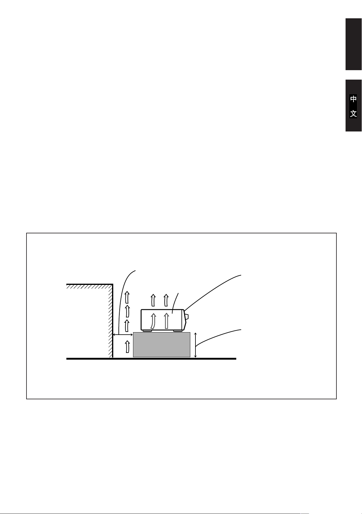
Caution: Proper Ventilation
To avoide risk of electric shock and fire and to protect from damage.
Locate the apparatus as follows:
Front: No obstructions open spacing.
Sides: No obstructions in 10 cm from the sides.
Top: No obstructions in 10 cm from the top.
Back: No obstructions in 15 cm from the back
Bottom: No obstructions, place on the level surface.
In addition, maintain the best possible air circulation as illustrated.
Spacing 15 cm or more
!=NR
!"#$%&'
!"#$%&'()*+,
!"#$%&'
!"#$%&'()
NM !"#$%&'()
NM !"#$%&'()
NR !"#$%&'()
!"#$%&' !(
!"#$ %&'()*+,-./01
Front
RX-80PGD
Wall or obstructions
!"#
Floor
Stand height 15 cm or more
!=NR=
G-2
Page 4
Table of Contents
English
Getting Started........................................................................................................................... 2
Before Installation.................................................................................................................... 2
Checking the Supplied Accessories ......................................................................................... 2
Switches, Buttons and Controls ............................................................................................... 3
Connecting the FM and AM Antennas .................................................................................... 5
Connecting the Speakers .......................................................................................................... 6
Connecting Audio/Video Components .................................................................................... 8
Connecting the Power Cord ................................................................................................... 11
Putting Batteries in the Remote Control ................................................................................ 11
Basic Operations ...................................................................................................................... 12
Turning the Power On and Off .............................................................................................. 12
Selecting the Source to Play................................................................................................... 12
Adjusting the Volume ............................................................................................................13
Selecting the Front Speakers.................................................................................................. 13
Muting the Sound................................................................................................................... 14
Recording a Source ................................................................................................................ 14
Basic Settings ........................................................................................................................... 15
Adjusting the Front Speaker Output Balance ........................................................................ 15
Listening at Low Volume (Loudness) ................................................................................... 15
Using the Sleep Timer............................................................................................................ 16
Selecting the Center Speaker Size ......................................................................................... 17
Using Visual Confirmation .................................................................................................... 18
One Touch Operation.............................................................................................................. 19
About the One Touch Operation ............................................................................................ 19
Using the One Touch Operation ............................................................................................ 19
Receiving Radio Broadcasts ................................................................................................... 20
Tuning in Stations Manually.................................................................................................. 20
Using Preset Tuning............................................................................................................... 21
Selecting the FM Reception Mode......................................................................................... 22
Assigning Names to Preset Stations....................................................................................... 23
Using the SEA Modes .............................................................................................................. 24
Selecting Your Favorite SEA Mode ...................................................................................... 24
Creating Your Own SEA Mode ............................................................................................. 25
Activating the Surround Sounds ............................................................................................ 26
Using the DAP Modes ........................................................................................................... 27
Using the DVD MULTI Playback Mode ............................................................................... 29
Using the Surround Modes .................................................................................................... 31
Using the On-Screen Display to Control the Receiver ......................................................... 37
COMPU LINK Remote Control System ............................................................................... 41
AV COMPU LINK Remote Control System ........................................................................ 42
Using the Remote Control for Operating JVC’s Audio/Video Components ..................... 44
Page 1
Operating Other Manufactures’ TV ..................................................................................... 48
Troubleshooting ....................................................................................................................... 50
Specifications............................................................................................................................ 51
This mark indicates that you can also use the menu function to do the
MENU
same operations.
Actual operations using the menu function are explained on the pages
indicated next to the marks.
Page 5

Getting Started
This section explains how to connect audio/video components and speakers to the receiver, and how to connect
the power supply.
Before Installation
General
• Be sure your hands are dry.
• Turn the power off to all components.
• Read the manuals supplied with the components you are going to connect.
Locations
• Install the receiver in a location that is level and protected from moisture.
• The temperature around the receiver must be between –5˚ and 35˚ C .
• Make sure there is good ventilation around the receiver. Poor ventilation could cause overheating and
damage the receiver.
Handling the receiver
• Do not insert any metal object into the receiver.
• Do not disassemble the receiver or remove screws, covers, or cabinet.
• Do not expose the receiver to rain or moisture.
Checking the Supplied Accessories
English
Check to be sure you have all of the following items, which are supplied with the receiver.
The number in the parenthesis indicates the quantity of the pieces supplied.
• Remote Control (1)
• Batteries (2)
• AM Loop Antenna (1)
• FM Antenna (1)
• Audio Signal Attenuating Cord (1)
• AV COMPU LINK Cable (1)
If anything is missing, contact your dealer immediately.
Page 2
Page 6

Switches, Buttons and Controls
English
Become familiar with the main switches and controls on your receiver before use.
12
RX-80P AUDIO/VIDEO CONTROL RECEIVER
STANDBY
POWER
345
ONETOUCH
OPERATION
DVD MULTI
p
MASTER VOLUME
–+
VIDEO1 VIDEO2 VCR1 TAPE/VCR DVD TV SOUND FM AM CD PHONO
DAP/SURROUND MODE
DAP/SURROUND/DVD MULTI
ADJUST
SETTING
LR
VIDEO AUDIO
q
w e r tyu i o9
6
SOURCE
12
_ON —OFF
DESIGNED BY JVC
SEA
ADJUST
87
JAPAN
SEA MODE
MEMORY
MEMORYTUNER
PHONESSPEAKERSVIDEO 2
Refer to the pages in parentheses for details.
Front Panel
1 Remote sensor (11)
2 Display (12)
3 ONE TOUCH OPERATION button and lamp (19)
4 MASTER VOLUME control (13)
5 DAP/SURROUND MODE button and lamp (27, 32)
6 SOURCE button and lamps (12)
7 SEA MODE button and lamp (24)
8 MEMORY button for SEA adjustments (25)
9 POWER button and STANDBY lamp (12)
p DVD MULTI button and lamp (12)
q DAP/SURROUND/DVD MULTI ADJUST button and
lamp (27, 29, 32)
w SETTING button and lamp (15)
e VIDEO 2 input jacks (10)
r Control % / fi / @ / # buttons
t SPEAKERS 1/2 buttons (13)
y TUNER button and lamp (20)
u PHONES jack (14)
i MEMORY button for presetting channels (21)
o SEA ADJUST button and lamp (25)
IMPORTANT
%%
fifi
@@
To use Control
% /
%%
fi /
fifi
##
@ /
# buttons (r) on the front
@@
##
panel:
What these buttons actually do depends on which function
you are trying to adjust. Before using these buttons, select
the function by pressing one of the function selecting
buttons (5, 6, 7, q, w, y, o), and being sure its lamp is
lit.
However, pressing MENU SET (c on the remote control)
%%
overrides the selected function and causes Control
@@
##
@ /
# button to act like
@@
##
%%
% /
%%
fifi
@@
##
fi /
@ /
# buttons (v) of the ON
fifi
@@
##
% /
%%
fifi
fi /
fifi
SCREEN CONTROL section of the remote control (though
a lamp for the selected function remains lit).
%%
fifi
@@
To return the Control
% /
%%
fi /
fifi
##
@ /
# buttons to their usual
@@
##
behavior under the selected function, press the function
button again.
Page 3
Page 7
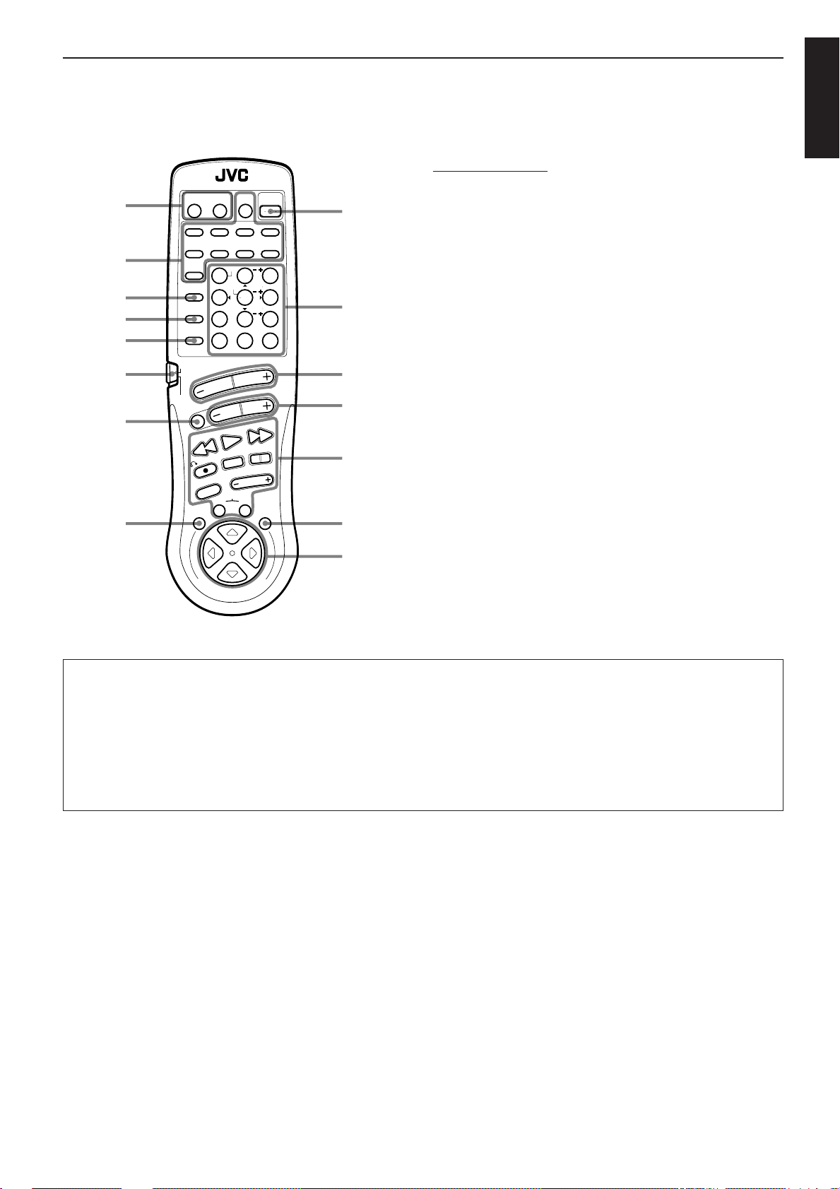
Remote Control
;
a
s
d
f
g
h
j
RM-SR80U REMOTE CONTROL
VCR
TV
POWER
POWER
VIDEO1 VIDEO2
TV
SOUND
FM/AM PHONOCD
DVD
MENU
CD
TEST
ENTER
DISC
VCD
EFFECT
DISC
VCD
SEA MODE DAP MODE SURR MODE
CONTROL
10
TV /VCR /TUNER
/ CD / DVD / VCD
VOLUME
SOUND
CONTROL
MUTING
PREV /
4 / REW
/ REC
TV/VIDEO
MENU
EXIT
CHANNEL
SELECT /
PLAY
STOP
CONTROL
TAPE VCR
AUDIO
DVD
POWER
MULTI
TAPE/VCR
VCR1
CNTRDELAY
213
REAR (L)
546
(REAR R)
87/P 9
+10
0
FM MODE/MUTINGRETURN
NEXT /
FF / ¢
PAUSE
TV VOLUME
MENU
SET
l
/
x
k
z
c
English
Remote Control Unit
; TV POWER and VCR POWER buttons (46, 47)
a Source selecting buttons (13)
s CD DISC button (45)
d VCD DISC button (47)
f VCD CONTROL button (47)
g Remote control mode selector (TV / VCR / TUNER / CD /
DVD / VCD, SOUND CONTROL) (12, 24)
h MUTING button (14)
j MENU EXIT button (37)
k AUDIO POWER button (12)
l • 10 keys for selecting preset channel (22)
• 10 keys for adjusting sound (24, 28, 30, 35)
• Operating buttons for audio/video components (44, 46)
/ VOLUME buttons (+/–) (13)
z CHANNEL buttons (+/–) (46, 47)
x Operating buttons for audio/video components (44, 46)
c MENU SET button (37)
v % / fi / @ / # buttons of the ON SCREEN CONTROL section
(37)
v
O
N
S
C
R
E
L
O
R
T
N
O
E
C
N
IMPORTANT
When using the remote control:
Check to see if its remote control mode selector (g) is set to the correct position.
Normally, set it to the “TV / VCR / TUNER / CD / DVD / VCD” position.
To activate the 10 keys for adjusting the sound, set it to the “SOUND CONTROL” position.
About % / fi / @ / # buttons (v) of the ON SCREEN CONTROL section on the remote control:
If you press these buttons, the menu function starts operating. So, make sure you are showing the on-screen display on the TV
before pressing these buttons.
Page 4
Page 8
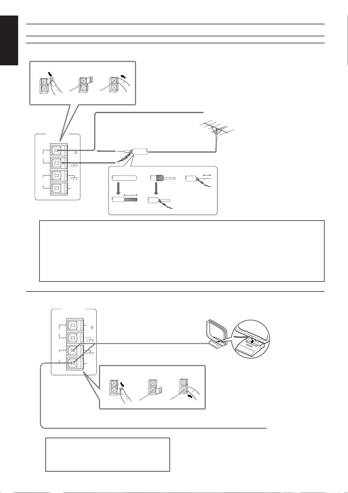
Connecting the FM and AM Antennas
FM Antenna Connections
English
1
LOOP
FM
AM
ANTENNA
2
FM
(75 )
GND
GND
AM
EXT
3
FM Antenna
4
1
20 mm
Outside FM Antenna Wire
2
Extend the FM wire antenna horizontally.
10 mm
3
How to strip the 75Ω coaxial cable and connect it to the FM terminals
1.
Strip back the outside covering of the 75Ω coaxial cable to expose the braided metallic mesh about 20 mm.
2. Pull the mesh back and twist it into a single connector, as shown in the illustration above.
If reception is poor, connect the outside antenna.
Before attaching a 75Ω coaxial cable (the kind
with a round wire going to an outside antenna),
disconnect the supplied FM antenna.
3. Strip the insulation about 10 mm back from the central wire.
4. Insert the twisted mesh and the central wire to the FM terminals, as shown in the illustration above.
AM Antenna Connections
ANTENNA
FM
AM
LOOP
FM
(75 )
GND
GND
AM
EXT
AM Loop Antenna
1
Turn the loop until you have
the best reception.
Snap the tabs on the loop into the slots of
2
3
the base to assemble the AM loop.
Outdoor Single Vinyl-covered Wire
Page 5
Note:
Make sure the antenna conductors do not touch any
other terminals, connecting cords and power cord.
This could cause poor reception.
If reception is poor, connect an outdoor single vinyl-covered
wire to the AM EXT terminal. (Keep the AM loop antenna
connected.)
Page 9
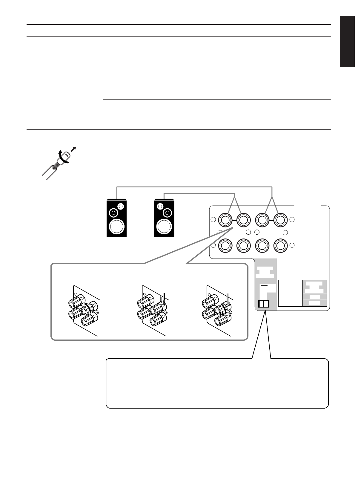
Connecting the Speakers
Connecting the front speakers
You can connect the following speakers:
• Two pairs of front speakers to produce normal stereo sound.
• One pair of rear speakers to enjoy the surround effect.
• One center speaker to produce more effective surround effect (to emphasize human voices).
• One subwoofer to enhance the bass.
For each speaker (except for subwoofer), connect the black (–) and red (+) terminals on the rear panel to the
black (–) and red (+) terminals marked on the speakers. For connecting a subwoofer, see page 7.
CAUTION:
Use speakers with the SPEAKER IMPEDANCE indicated by the speaker terminals.
Cut, twist and remove the insulation at the end of each speaker signal cable first, and then, connect the front
speakers to the FRONT SPEAKERS terminals by using the cables.
You can connect two pairs of front speakers (one pair to the FRONT SPEAKERS 1 terminals, and another
pair to the FRONT SPEAKERS 2 terminals).
English
1 Turn the knob
counterclockwise.
1
RIGHT
FRONT SPEAKERS
1
2
CAUTION:SPEAKER IMPEDENCE
SPEAKER
IMPEDANCE
/ OHMS
4 ~ 6
8 ~ 16
SPEAKER
LOAD
SELECTOR
LOW
HIGH
Right SpeakerLeft Speaker
2 Insert the speaker
signal cable.
1
RIGHT
RIGHT LEFT
1
+
2
3 Turn the knob
clockwise.
1
RIGHT
–+–
SPEAKER
SELECTOR
LOAD
LOW
HIGH
Notes:
• To obtain the best possible output power from the receiver, and to prevent the receiver from
being overheated, the receiver has the SPEAKER LOAD SELECTOR which should be set to
match the impedance of the connected speakers.
Set this selector according to the indications by the FRONT SPEAKERS terminals.
• When you connect two pairs of the speakers to the FRONT SPEAKERS terminals, use the
speakers having the impedance within the same range.
Page 6
Page 10
RIGHT LEFT
REAR
SPEAKERS
1
2
CENTER
SPEAKER
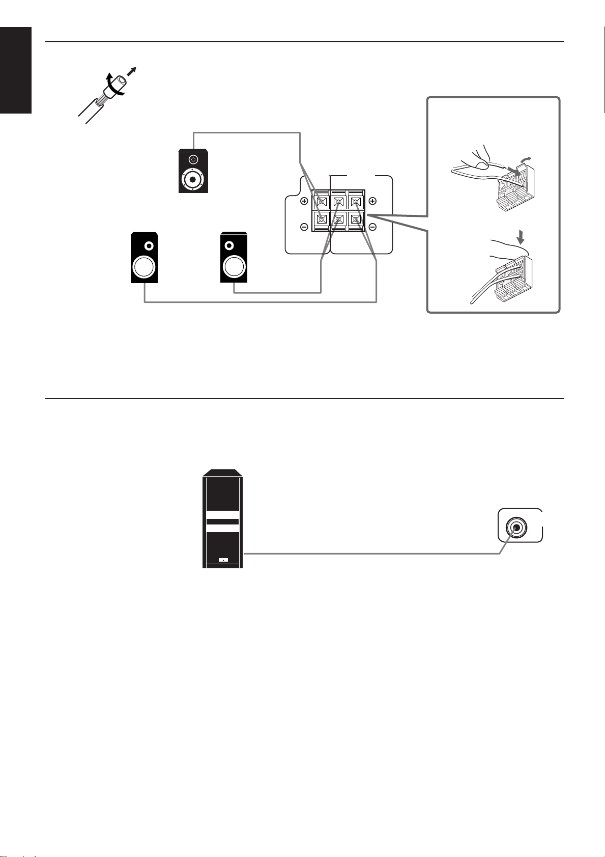
Connecting the rear and center speakers
SUBWOOFER
OUT
English
Cut, twist and remove the insulation at the end of each speaker signal cable first, and then, connect rear
speakers to the REAR SPEAKERS terminals and a center speaker to the CENTER SPEAKER terminals by
using the cables.
Open the terminal and
then insert the speaker
signal cable.
Center speaker
Left rear speaker
Note:
You can register the center speaker size after you finish its connection. If you register it, you do not have to
set the center speaker mode when setting the surround mode.
(If you do not use a center speaker, register that information.) See page 17.
Connecting the subwoofer speaker
You can enhance the bass by connecting a subwoofer.
Connect the input jack of a powered subwoofer to the SUBWOOFER OUT jack on the rear panel, using a cable
with RCA pin plugs.
Right rear speaker
Close the terminal.
Page 7
Powered subwoofer
Page 11
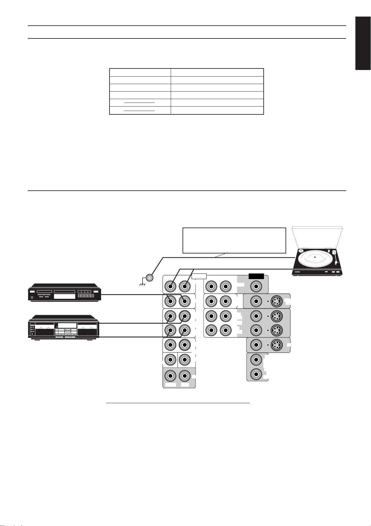
Connecting Audio/Video Components
You can connect the following audio/video components to this receiver using cables with RCA pin plugs (not
supplied). Refer also to the manuals supplied with your components. If you want to connect a component not
listed in the table below, refer to the manual supplied with it.
Audio Components Video Components
• Turntable • DVD (Digital Video Disc) player
• CD player • VCD (Video CD) player
• Cassette deck • TV
Notes:
• If you connect a sound-enhancing device such as a graphic equalizer between the source components and
this receiver, the sound output through this receiver may be distorted.
• You can connect either a cassette deck or a VCR to the TAPE/VCR jacks, whichever you want.
• Any turntables incorporating a small-output cartridge such as an MC (moving-coil type) must be connected
to this receiver through a commercial head amplifier or step-up transformer. Direct connection may result
in insufficient volume.
Audio component connections
English
• VCR(s)
• Video camera
CD player
Cassette deck
Turntable
If an earth cable is provided for your turntable,
connect the cable to the screw marked GND
on the rear panel.
To audio output
To audio output
To audio input
To audio output
GND
SUBWOOFER
RIGHT LEFT RIGHT LEFT
RIGHT LEFT
AUDIO VIDEO
PHONO
CD
OUT
(REC)
TAPE
VCR
IN
(PLAY)
FRONT
DVD
CENTER
REAR
VIDEO1
TV
SOUND
OUT
(REC)
VCR1
IN
(PLAY)
OUT
(REC)
TAPE
VCR
IN
(PLAY)
MONITOR
OUT
DVD
If your audio components have a COMPU LINK-3 terminal
The COMPU LINK remote control system allows you to control other JVC audio components from the
receiver or vice versa.
Connect your audio components and the receiver with the cable (monaural mini-plug supplied with those
components) as well as the connection above.
For detailed information about the connection and the COMPU LINK-3 remote control system, see page 41.
Notes:
• If you want to operate a cassette deck using the COMPU LINK remote control system, connect the cassette
deck to the TAPE/VCR jacks, not to the VCR1 jacks.
• The COMPU LINK-3 remote control system is the upgraded version of the COMPU LINK-1 and COMPU
LINK-2. Even if your component has the COMPU LINK-1 or COMPU LINK-2 jacks, you can still connect
it in the COMPU LINK-3 remote control system, but some functions may not work correctly.
Page 8
Page 12
Video component connections
IN
IN
(PLAY)
If your video components have S-video (Y/C-separation) terminals, connect them using S-video cables (not
supplied).
English
IMPORTANT
This receiver is equipped with both the composite video and S-video input/output terminals for connecting video components.
You do not have to connect both the composite video and S-video terminals.
However, remember that the video signals from the composite video input terminals on the rear are output only through
the composite video output terminals, while the ones from the S-video input terminals on the rear are output only
through the S-video output terminals.
Therefore, if a recording video equipment and a playing video equipment are connected to the receiver through the different video
terminals, you cannot record the picture from the playing equipment on the recording equipment. In addition, if the TV and a
playing video equipment are connected to the receiver through the different video terminals, you cannot view the playback picture
from the playing equipment on the TV.
To view and record the playback picture from the video components connected to the VIDEO1,VIDEO2 and TAPE/VCR jacks,
you must connect the TV and the recording video equipment through the composite video terminals.
Note:
When connecting an audio/video component (ex.: Video CD player) with “karaoke” — singing along — function, use the audio signal attenuating
cord supplied with this receiver. If not, sound may be distorted.
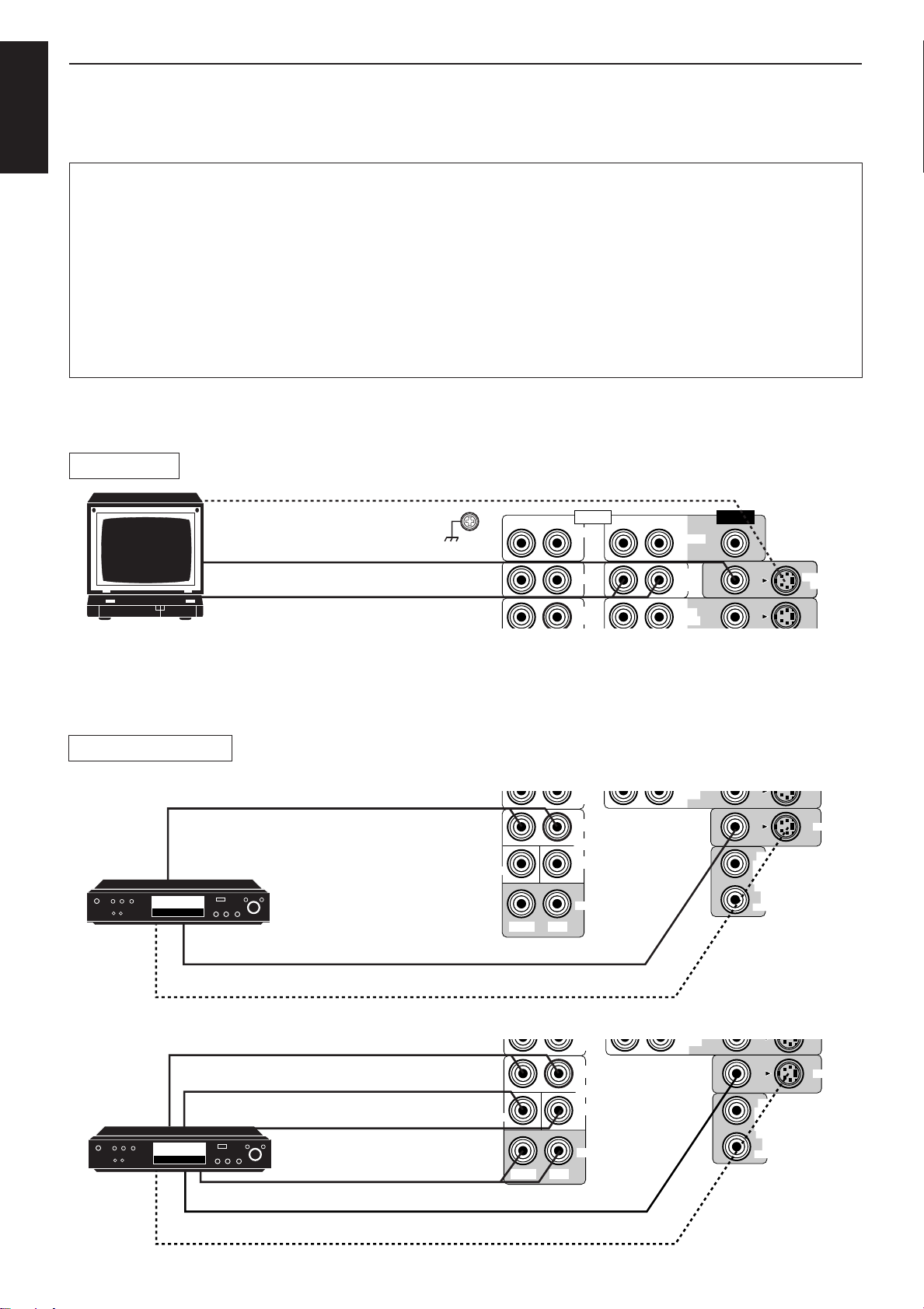
TV connection
To S-Video input (for better playback picture quality)
To composite video input (See note below.)
To audio output
TV
DVD player connection
Connecting these video components through the S-video input/output terminals will give you can get better
picture playback quality.
GND
RIGHT LEFT RIGHT LEFT
AUDIO VIDEO
PHONO
CD
OUT
(REC)
VIDEO1
TV
SOUND
OUT
(REC)
Notes:
• When connecting a JVC TV:
– If you use the AV COMPU LINK remote control system to operate the TV, connect the receiver to the
Video Input 2 jack on the TV.
– If you do not use the AV COMPU LINK remote control system to operate TV, connect the receiver to the
Video Input 1 jack on the TV.
• Use the video components of the PAL color system.
MONITOR
OUT
• When you play back a disc on the DVD player in stereo (or the audio output setting of the DVD player is mixed to two front channels):
(PLAY)
OUT
(REC)
TAPE
VCR
IN
(PLAY)
DVD
DVD player
To front left/right channel audio output
(or to audio mixed output if necessary)
DVD
SUBWOOFER
(PLAY)
FRONT
DVD
CENTER
REAR
RIGHT LEFT
To composite video output
To S-video output (for better playback picture quality)
• When you play back a disc on the DVD player with its analog discrete output mode (5.1 CH reproduction) selected:
(PLAY)
DVD player
To front left/right channel audio output
To subwoofer audio output
To center channel audio output
DVD
SUBWOOFER
RIGHT LEFT
FRONT
DVD
CENTER
REAR
OUT
(REC)
TAPE
VCR
IN
(PLAY)
DVD
To rear left/right channel audio output
To composite video output
Page 9
To S-video output (for better playback picture quality)
Page 13
RX-80P AUDIO/VIDEO CONTROL RECEIVER
STANDBY
POWER
MASTER VOLUME
–+
SEA MODE
PHONESSPEAKERSVIDEO 2
LR
VIDEO AUDIO
MEMORYTUNER
DAP/SURROUND MODE
VIDEO1 VIDEO2 VCR1 TAPE/VCR DVD TV SOUND FM AM CD PHONO
DAP/SURROUND/DVD MULTI
ADJUST
SETTING
ONE TOUCH
OPERATION
12
SOURCE
_ON —OFF
DVD MULTI
MEMORY
SEA
ADJUST
VIDEO
AUDIO
LR
VIDEO 2
DESIGNED BY JVC
JAPAN
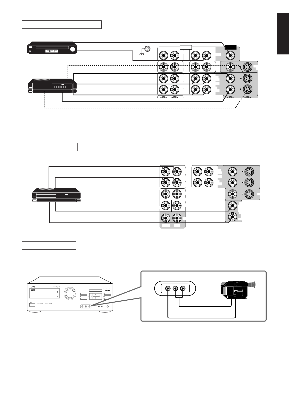
VCR and Video CD player connection
Video CD player
VCR
VHS
To composite video output
To S-Video output (for better playback picture quality)
Another VCR connection
To audio input
VCR
To audio output
VHS
To composite video input
To composite video output
To composite video output
To audio output
To S-Video input (for better
playback picture quality)
To composite video input
To audio input
To audio output
Note:
When connecting an audio/video component (ex.: Video CD player) with “karaoke” — singing along —
function, use the audio signal attenuating cord supplied with this receiver. If not, sound may be distorted.
If you are not using a cassette deck, you can connect another VCR to the TAPE/VCR jacks.
GND
SUBWOOFER
RIGHT LEFT RIGHT LEFT
RIGHT LEFT
AUDIO VIDEO
PHONO
CD
OUT
(REC)
TAPE
VCR
IN
(PLAY)
FRONT
DVD
CD
OUT
(REC)
TAPE
VCR
IN
(PLAY)
FRONT
DVD
CENTER
REAR
VIDEO1
TV
SOUND
OUT
(REC)
VCR1
IN
(PLAY)
TV
SOUND
OUT
(REC)
VCR1
(PLAY)
English
MONITOR
OUT
DVD
OUT
MONITOR
OUT
IN
DVD
OUT
(REC)
TAPE
VCR
IN
(PLAY)
Video camera connection
You can use the VIDEO 2 input jacks on the front panel. These jacks are convenient for connecting and
disconnecting the component frequently.
Video camera
To audio output
To video output
If your video components have an AV COMPU LINK terminal
The AV COMPU LINK remote control system allows you to control other JVC video components from the
receiver or vice versa.
For detailed information about the connection and the AV COMPU LINK remote control system, see page 42.
Notes:
• The AV COMPU LINK remote control system cannot control the video components connected to the
VIDEO1, VIDEO2, and TAPE/VCR jacks on the receiver, but can control only the VCR connected to the
VCR1 jacks and the DVD player connected to the DVD jacks. You cannot connect two VCRs into the AV
COMPU LINK remote control system.
• Some VCRs use the AV COMPU LINK jacks for the SWAP editing. However, you cannot use both the AV
COMPU LINK remote control and the SWAP editing at the same time. For the SWAP editing, see the manual
supplied with the VCR.
Page 10
Page 14
Connecting the Power Cord
English
Before plugging the receiver into an AC outlet, make sure that all connections have been made.
When the power cord is connected, the STANDBY lamp above the POWER button lights up.
Keep the power cord away from the connecting cables for the TV, VCR, and antenna. The power cord may
cause noise or screen interference. We recommend that you use a coaxial cable to connect the antenna, since
it is well-shielded against interference.
Notes:
• A small amount of power is always consumed even in standby mode. To switch off the power completely,
• If the power cord is unplugged or a power failure occurs, preset settings will be erased in a few days.
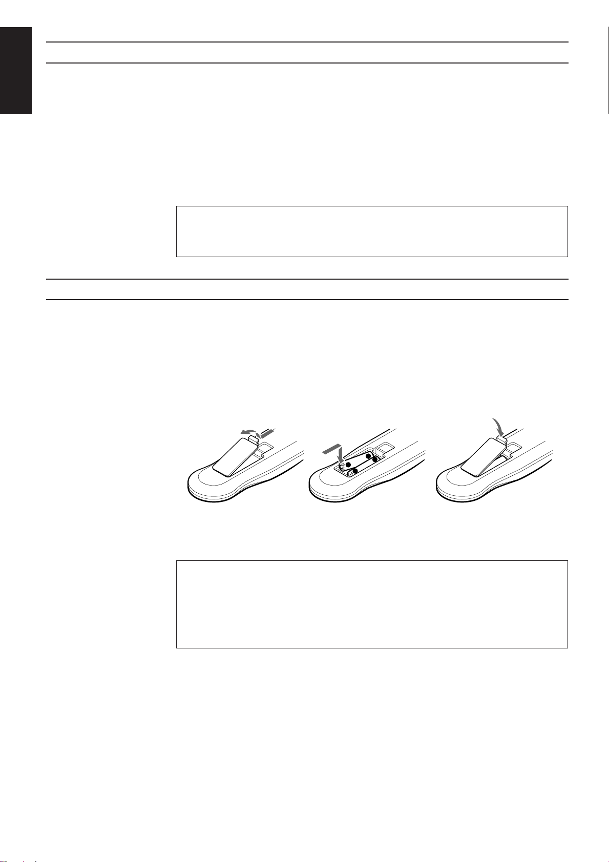
Putting Batteries in the Remote Control
Before using the remote control, put two supplied batteries first. When using the remote control, aim the
remote control directly at the remote sensor on the receiver.
1. On the back of the remote control, remove the cover as illustrated.
2. Insert batteries. Make sure to observe the proper polarity: (+) to (+) and (–) to (–).
3. Replace the cover in.
unplug the power cord from the AC outlet.
CAUTIONS:
• Do not touch the power cord with wet hands.
• Do not pull on the power cord to unplug the cord. When unplugging the cord, always grasp
the plug so as not to damage the cord.
R03 (UM-4)/AAA (24F)
-
+
+
-
If the range or effectiveness of the remote control decreases, replace the batteries. Use two R03 (UM-4)/AAA
(24F) type dry-cell batteries.
CAUTIONS:
Follow these precautions to avoid leaking or cracking cells:
• Place batteries in the remote control so they match the polarity indicated: (+) to (+) and (–)
to (–).
• Use the correct type of batteries. Batteries that look similar may differ in voltage.
• Always replace both batteries at the same time.
• Do not expose batteries to heat or flame.
Page 11
Page 15
Basic Operations
DVD MULTI
MUTE AUTO TUNED STEREO
SURROUND PRO LOGIC LOGIC3CH
THEATER–1 THEATER–2
SEA DAP
H.PHONE LOUDNESS
VOLUMEVISUAL CONFIRMATION
CH–
MHz
kHz
FM
AM
SLEEP
100 1k 10k
TV / VCR / TUNER
/ CD / DVD / VCD
SOUND
CONTROL
Turning the Power On and Off
The following operations are commonly used when you play any sound source.
English
IMPORTANT
When using the Remote Control, check to see if its remote control mode selector is set to the “TV
/ VCR / TUNER / CD / DVD / VCD” position.
STANDBY
POWER
STANDBY
POWER
Front panel
AUDIO
POWER
Remote Control
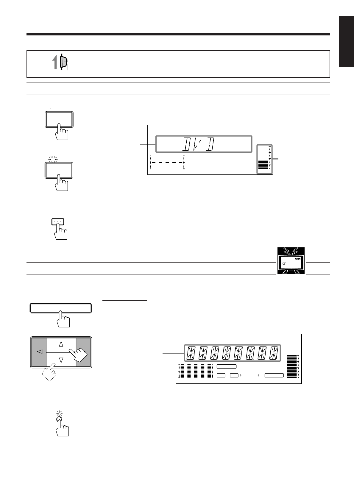
Selecting the Source to Play
On the front panel:
To turn on the power, press POWER.
The STANDBY lamp goes off. The name of the current source appears on the display.
Current source
name appears
VOLUME100 1k 10k
To turn off the power, press POWER again.
The STANDBY lamp lights up.
From the remote control:
To turn on the power, press AUDIO POWER.
The STANDBY lamp goes off. The name of the current source appears on the display.
To turn off the power, press AUDIO POWER again.
The STANDBY lamp lights up.
Volume level is also
shown here
whenever the power
is on.
See also
page 37.
MENU
SOURCE
Front panel
You need to select the source before you start playing any source.
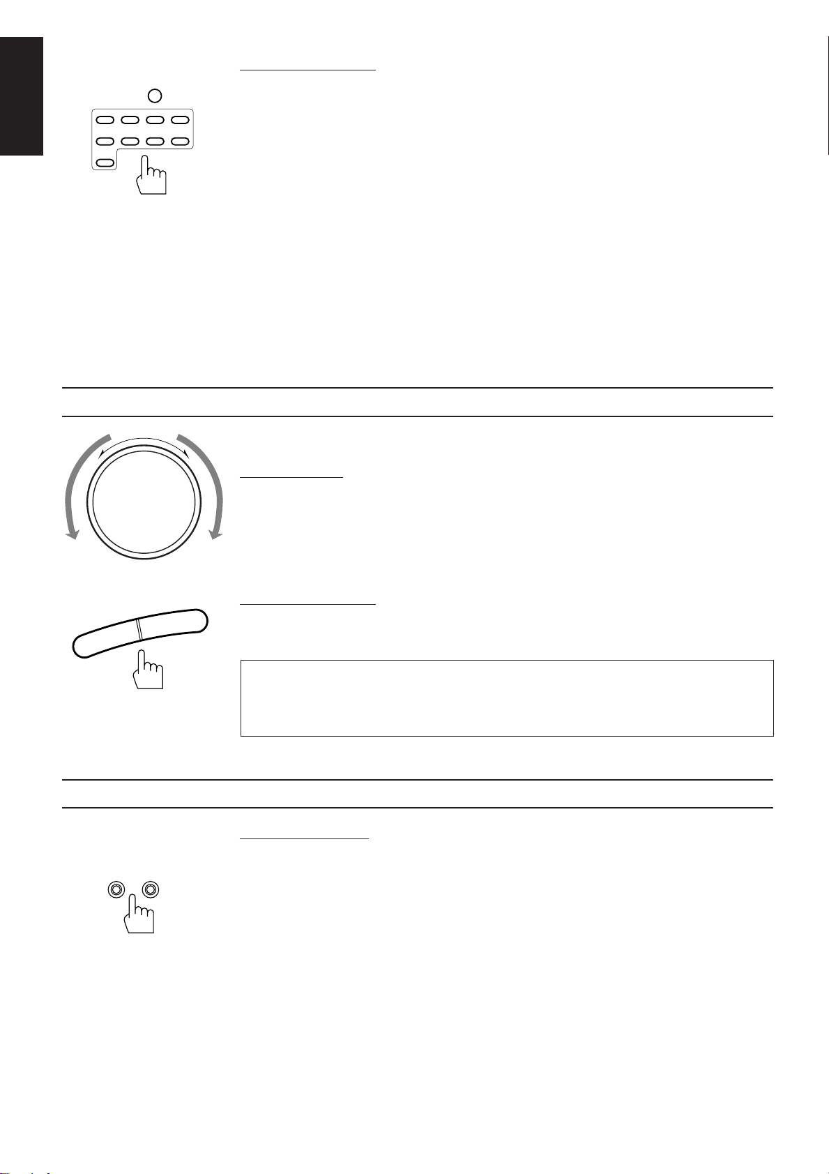
On the front panel:
1. Press SOURCE so that the Control % / fi / @ / # buttons work for selecting the source.
2. Press Control % / fi until the source name you want appears on the display.
The selected source lamp also lights up.
Selected source
name appears
For selecting DVD MULTI playback mode as the source:
Press DVD MULTI so that the lamp above the button lights up.
Each time you press the button, the DVD MULTI playback mode turns on and off, and the “DVD” and
“DVDMULTI” alternately appears on the display.
• Select “DVD” when you play back a disc in stereo or the audio output setting of the DVD player is mixed
to two front channels.
• Select “DVDMULTI” when you play back a disc on the DVD player with its analog discrete output mode
(5.1 CH reproduction) selected. To enjoy “DVDMULTI” mode, see page 29.
Notes:
• You can change the source to another even while the DVD MULTI lamp is lit.
• You can also select “DVDMULTI” by pressing Control
@
/ # when “DVD” is selected.
Page 12
Page 16
English
VIDEO1 VIDEO2
FM/AM PHONOCD
SOUND
TV
DVD
Remote Control
Adjusting the Volume
DVD
MULTI
VCR1
TAPE/VCR
From the remote control:
Press one of the Source selecting buttons you want.
DVD Play back a stereo digital video disc.
DVD MULTI Play back a digital video disc using the analog discrete output mode (5.1 CH reproduction)
on the DVD player.
Each time you press the button, the DVD MULTI playback mode turns on and off.
VIDEO1 Play back a video source on the video component connected to the VIDEO1 jacks.
VIDEO2 Play back a video source on the video component connected to the VIDEO2 jacks.
VCR1 Play back a video source on the video component connected to the VCR1 jacks.
TV SOUND Listen to TV sounds.
FM/AM* Listen to the radio.
Each time you press the button, the band alternates between FM and AM.
TAPE/VCR* Listen to a cassette tape (or play back a video source) connected to the TAPE/VCR jacks.
CD* Listen to a CD.
PHONO* Listen to a record.
Note:
When you press one of the Source selecting buttons marked above with an asterisk (*), the receiver
automatically turns on.
MASTER VOLUME
–
+
Front panel
VOLUME
+
–
Remote Control
Selecting the Front Speakers
SPEAKERS
12
When you change the volume level, the volume level is shown on the display.
On the front panel:
To increase the volume, turn MASTER VOLUME clockwise.
To decrease the volume, turn MASTER VOLUME counterclockwise.
Note:
When you turn MASTER VOLUME rapidly, the volume level also changes rapidly.
When you turn MASTER VOLUME slowly, the volume level also changes slowly.
From the remote control:
To increase the volume, press VOLUME +.
To decrease the volume, press VOLUME –.
CAUTION:
Always set the volume level to the minimum before starting any source. If the volume level is
left turned up, the sudden blast of sound energy can permanently damage your hearing and/
or ruin your speakers.
On the front panel only:
When you have connected two pairs of the front speakers, you can select which to use. Pressing SPEAKERS
1 or SPEAKERS 2 to set it in the _ON position activates the respective pair of the speakers.
Page 13
_ON —OFF
Front panel
To use the speakers connected to the FRONT SPEAKERS 1 terminals, press SPEAKERS 1 to set it in
the _ON position, and press SPEAKERS 2 to set it in the —OFF position.
To use the speakers connected to the FRONT SPEAKERS 2 terminals, press SPEAKERS 2 to set it in
the _ON position, and press SPEAKERS 1 to set it in the —OFF position.
To use both pairs of the speakers, press both SPEAKERS 1 and 2 to set them in the _ON position.
To use neither pair of the speakers, press both SPEAKERS 1 and 2 to set them in the —OFF position.
Note:
When only one set of the speakers is connected to either the FRONT SPEAKERS
press both SPEAKERS 1 and 2 to set them in the
_
ON position. If you do, no sound comes out of the front
1
or 2 terminals, do not
speakers.
Page 17
Listening with Headphones
A standard pair of headphones can be connected to the PHONES jack on the front panel.
Muting the Sound
MUTING
Remote Control
Recording a Source
To listen with only headphones, press both SPEAKERS 1 and 2 to set them in the —OFF position.
No sound comes out of the front speakers.
CAUTION:
Be sure to turn down the volume before connecting or putting on headphones, as high volume
can damage both the headphones and your hearing.
From the remote control only:
To mute the sound through all the speakers and headphones connected, press MUTING so that
“MUTE” appears on the display and the volume turns off.
To cancel the mute, press MUTING again so that “OFF” appears on the display.
Turning MASTER VOLUME or pressing VOLUME +/– also restores the sound at the previous volume level.
You can record any source playing through the receiver to the cassette deck (or VCR) connected to the TAPE/
VCR jacks and the VCR connected to the VCR1 jacks at the same time.
While recording, you can listen to the selected sound source at whatever sound level you like, without affecting
the sound levels of the recording.
English
Note:
The output volume level, SEA, DAP and surround adjustments cannot affect the recording.
Page 14
Page 18

Basic Settings
Some of the following settings are required after connecting and positioning your speakers in your listening
English
Adjusting the Front Speaker Output Balance
room, while others will make operations easier.
If the sounds you hear from the front right and left speakers are unequal, you can adjust the speaker output
balance.
See also
page 37.
MENU
SETTING
Front panel
On the front panel only:
1. Press SETTING so that the Control % / fi / @ / # buttons work for adjusting the balance.
The lamp next to the button lights up.
2. Press Control % / fi until “BALANCE” appears on the display.
3. Press Control @ / # to adjust the balance.
• Pressing Control @ decreases the right channel output.
• Pressing Control # decreases the left channel output.
Listening at Low Volume (Loudness)
Human ears are not sensitive to bass at low volume. To compensate for this, the loudness function
automatically boosts the bass level as you lower the volume.
See also
page 38.
MENU
SETTING
Front panel
Note:
The loudness function affects the front speaker sounds only.
On the front panel only:
1. Press SETTING so that the Control % / fi / @ / # buttons work for setting the loudness
function.
The lamp next to the button lights up.
2. Press Control % / fi until “LOUDNESS” appears on the display.
3. Press Control @ / # to set the loudness function to “ON” or “OFF.”
• Select “ON ” to activate the loudness function.
The LOUDNESS indicator lights up on the display.
• Select “OFF” to cancel it.
The indicator goes off.
Page 15
Page 19

Using the Sleep Timer
SETTING
Front panel
See also
page 38.
MENU
Using the Sleep Timer, you can fall asleep to music and know the receiver will turn off by itself rather than
play all night.
On the front panel only:
1. Press SETTING so that the Control % / fi / @ / # buttons work for setting the Sleep Timer
The lamp next to the button lights up.
2. Press Control % / fi until “<SLEEP>” appears on the display.
3. Press Control @ / # to set the shut-off time.
Each time you press the button, the shut-off time on the display changes as follows:
The SLEEP indicator lights up on the display.
2010 30 40 50 60 70 80
(Canceled)
0
When the shut-off time comes
The receiver turns off automatically.
To check or change the time remaining until the shut-off time
1. Press SETTING, if necessary, so that the Control % / fi / @ / # buttons work for setting the
Sleep Timer.
2. Press Control % / fi, if necessary, until “<SLEEP>” appears on the display.
3. Press Control @ / # once.
The remaining time until the shut-off time appears in minutes.
• To change the shut-off time, press Control @ / # repeatedly.
English
To cancel the Sleep Timer
Press Control @ / # repeatedly in step 3 above until “0” appears on the display. (The SLEEP indicator goes
off.) Turning off the power also cancels the Sleep Timer.
Page 16
Page 20

Selecting the Center Speaker Size
See also
page 38.
MENU
English
DAP/SURROUND MODE
SETTING
You can register the information on the center speaker after all connections are completed.
If you do this registration first, you do not have to adjust the center speaker mode when you want to activate
the surround sound. However, to register the information, first you have to turn on the surround mode. (You
cannot select the center speaker size when the surround mode is off.)
On the front panel only:
1. Press DAP/SURROUND MODE so that the Control % / fi / @ / # buttons work for selecting
the DAP/surround mode.
The lamp next to the button lights up.
2. Press Control @ / # until the SURROUND indicator lights up on the display.
3. Press SETTING so that the Control % / fi / @ / # buttons work for selecting the center speaker
size.
The lamp next to the button lights up.
4. Press Control % / fi until “CNTR SPK” (Center Speaker) appears on the display.
5. Press Control @ / # to select the appropriate item about your center speaker.
Each time you press the button, the display changes to show the following:
LARGE SMALL NO
LARGE: Select this mode when the size of the center speaker is the same as that of the
front speakers.
SMALL: Select this mode when the size of the center speaker is smaller than that of the
front speakers.
NO: Select this mode when you do not use a center speaker.
(You cannot select this mode when “3CHLOGIC” is selected for the surround
mode.)
Front panel
Note:
This center speaker size setting is so related to the center mode setting for the surround mode that changing
this setting affects and changes the center mode to a relevant mode, and vice versa.
For example;
• If you select “LARGE,” the center mode is automatically set to “WIDE,” and vice versa.
• If you select “SMALL,” the center mode is automatically set to “NORMAL,” and vice versa.
• If you select “NO,” the center mode is automatically set to “PHANTOM” for Pro Logic and Theater
Surround, and vice versa.
Page 17
Page 21

Using Visual Confirmation
SETTING
See also
page 38.
MENU
When you operate the receiver, you can see what you are doing, by showing it on the TV screen.
To use this function, you need to connect the TV to the MONITOR OUT jack on the rear panel (see page 9),
and set the TV’s input mode to the proper position to which the receiver is connected.
When the TV’s input mode is for TV, you cannot see the on-screen display.
On the front panel only:
1. Press SETTING so that the Control % / fi / @ / # buttons work for setting Visual
Confirmation.
The lamp next to the button lights up.
2. Press Control % / fi until “VCONFIRM” appears on the display.
3. Press Control @ / # to set Visual Confirmation to “ON” or “OFF.”
• Select “ON ” to activate Visual Confirmation.
The VISUAL CONFIRMATION indicator lights up on the display.
• Select “OFF” to cancel it.
The indicator goes off.
English
Front panel
EXAMPLES:
When changing the source:
The SOURCE menu appears on the TV screen.
When adjusting the front speaker output balance:
The SETTING menu appears on the TV screen.
When selecting your favorite SEA mode:
The SEA MODE menu appears on the TV screen.
Page 18
Page 22

One Touch Operation
English
About the One Touch Operation
This receiver can memorize the optimum sound settings for each playing source.
JVC’s One Touch Operation function is used to assign and store different sound settings for each different
playing source. By using this function, you don’t have to change the settings every time you change the source.
The stored settings for the newly selected source are automatically recalled.
The following can be stored for each source:
• Volume level (see page 13)
• Balance (see page 15)
• Loudness (see page 15)
• SEA modes (see page 24)
• DAP mode settings (see page 27)
• DVD MULTI playback mode settings (see page 29)
• Surround mode settings (see page 32)
Notes:
• If the source is FM or AM, the One Touch Operation function works only when the preset channels from
1 — 20 are tuned in. You can assign a different setting for each preset channel.
• The DAP mode, DVD MULTI playback mode, and surround mode cannot be used at the same time.
Using the One Touch Operation
On the front panel only:
ONE TOUCH
OPERATION
Front panel
To store the sound settings
1. Press ONE TOUCH OPERATION.
2. Adjust the sound using the functions listed above.
To recall the sound settings
With the ONE TOUCH OPERATION lamp lit, the settings for the currently selected source is recalled, and
appears on the display when the source is selected.
To cancel the One Touch Operation function
Press ONE TOUCH OPERATION so that the lamp goes off.
(Even though the One Touch Operation function is canceled, the recalled sound effects remain active.)
The ONE TOUCH OPERATION lamp lights up, then the previously memorized settings are recalled
and appear on the display in turn.
The newly adjusted settings are memorized.
Page 19
Page 23

Receiving Radio Broadcasts
You can browse through all the stations or use the preset function to go immediately to a particular station.
Tuning in Stations Manually
On the front panel only:
MEMORYTUNER
1. Press TUNER so that the Control % / fi / @ / # buttons work for tuner settings.
The lamp next to the button lights up.
2. Press Control % / fi until “<FM AM>” appears on the display.
3. Press Control @ / # to select the band.
Each time you press the button, the band alternates between FM and AM.
4. Press Control % / fi until “–TUNING+” appears on the display.
5. Press Control @ / # until you find the frequency you want.
• Pressing Control @ decreases the frequency.
• Pressing Control # increases the frequency.
Notes:
• When you hold down Control @ / # in step 5, the frequency keeps changing until you press the button again
or a station is tuned in.
• When a station of sufficient signal strength is tuned in, the TUNED indicator lights up on the display.
When an FM stereo program is received, the STEREO indicator also lights up.
MENU
See also
page 39.
English
Front panel
Page 20
Page 24

Using Preset Tuning
See also
page 39.
MENU
English
To store the preset stations
Once a station is assigned to a channel number, the station can be quickly tuned. You can preset up to 40
stations at random.
On the front panel only:
1. Tune in the station you want to preset (see above).
If you want to store the FM reception mode for this station, select the FM reception mode you want.
See page 22 for details.
MEMORYTUNER
2. Press MEMORY (next to the TUNER button).
“CH-” appears and the channel number position starts flashing on the display for about 5 seconds.
3. Press Control % / fi to select a channel number while the channel number position is flashing.
• Pressing Control % increases the number.
• Pressing Control fi decreases the number.
Note:
You can use the 10 keys on the remote control to select the preset number. When using the 10 keys, be sure
that they are activated for tuner, not for the CD and others. (See page 44.)
4. Press MEMORY (next the TUNER button) again while the selected channel number is flashing
on the display.
The selected channel number stops flashing.
MEMORYTUNER
The station is assigned to the selected channel number.
5. Repeat steps 1 to 4 until you store all the stations you want.
Front panel
To tune in a preset station
MEMORYTUNER
To cancel a stored preset station
Storing a new station on a used number erases the previously stored one.
CAUTION:
Preset stations may be erased when power is cut off to the receiver, as when it is unplugged
from the AC outlet or a power failure occurs. If the preset stations are lost, simply set the stations
again.
On the front panel:
1. Press TUNER so that the Control % / fi / @ / # buttons work for tuner settings.
The lamp next to the button lights up.
2. Press Control % / fi until “–PRESET+” appears on the display.
3. Press Control @ / # to select a preset channel.
Each time you press the button, the preset channels changes.
• Pressing Control @ changes preset channels in decreasing order.
• Pressing Control # changes preset channels in increasing order.
Page 21
Front panel
Page 25

FM/AM
From the remote control:
1. Press FM/AM.
Each time you press the button, the band alternates between FM and AM.
CNTRDELAY
MENU
213
TEST
EFFECT
SEA MODE DAP MODE SURR MODE
10
REAR (L)
ENTER
546
(REAR R)
87/P 9
+10
0
FM MODE/MUTINGRETURN
2. Press 10 keys to select a preset channel number.
• For channel number 5, press 5.
• For channel number 15, press +10 then 5.
• For channel number 20, press +10 then 10.
• For channel number 30, press +10, +10, then 10.
Note:
When you use the 10 keys on the remote control, be sure that they are activated for tuner, not for the CD
and others. (See page 44.)
Remote Control
Selecting the FM Reception Mode
You can change the FM reception mode while listening an FM broadcast.
MEMORYTUNER
You can also store the FM reception mode for each preset station. (See page 21.)
On the front panel:
1. Press TUNER so that the Control % / fi / @ / # buttons work for tuner settings.
The lamp next to the button lights up.
2. Press Control % / fi until “FM MODE” appears on the display.
3. Press Control @ / # to select either “AUTO” or “MONO.”
• Normally select “AUTO.”
• When an FM stereo broadcast is hard to receive or noisy, select “MONO.”
English
See also
page 39.
MENU
Front panel
DAP MODE
0
FM MODE/MUTING
Remote Control
AUTO: When a program is broadcast in stereo, you will hear stereo sound; when in
monaural, you will hear monaural sounds. This mode is also useful to suppress
static noise between stations.
The MUTE AUTO indicator lights up on the display.
MONO: Reception will be improved although you will lose the stereo effect. In this
mode, you will hear noise while tuning into the stations.
The MUTE AUTO indicator goes off on the display.
From the remote control:
Press FM MODE/MUTING.
Each time you press the button, “AUTO” and “MONO” is alternately selected, and appears on the
display.
Note:
When using the FM MODE/MUTING button, be sure that the 10 keys are activated for tuner, not for the CD
and others. (See page 44.)
Page 22
Page 26

Assigning Names to Preset Stations
VISUAL CONFIRMATION
CH–
100 1k 10k
VISUAL CONFIRMATION
CH–
100 1k 10k
See also
page 39.
MENU
English
You can assign a name of up to five characters to each preset station (from preset channel number 1 to 20).
When a preset station is tuned in, its assigned name will appear on the display.
On the front panel only:
1. Tune in a preset station (preset channel number 1 to 20).
See page 21 for details.
MEMORYTUNER
2. Press MEMORY (next to the TUNER button).
The preset channel number starts flashing.
Note:
If you press Control
%
/ fi while the preset
channel number is flashing, you can change
the preset channel number.
3. Press Control # (or @) until the first character
position starts flashing.
CH–
100 1k 10k
VISUAL CONFIRMATION
4. Press Control % / fi to select a character.
You can use characters listed below.
MEMORYTUNER
Front panel
5. When a character you want appears, press
Control # (or @).
The next (or previous) character position starts
flashing.
CH–
100 1k 10k
VISUAL CONFIRMATION
6. Repeat steps 4 and 5 to enter up to five characters.
7. Press MEMORY (next to the TUNER button) again, while the last selected character is
flashing, after you have assigned a name.
To erase the input characters
Insert blanks using the same procedure described above.
Available characters
Blank
Page 23
CBADEGFHIJKLMNO
SRQTUWVXYZ01234P
87695
Page 27

Using the SEA Modes
SEA MODE
COUNTRY
JAZZ
ROCK MUSICAL MOVIE
USERMODESEA OFF
The SEA (Sound Effect Amplifier) modes give you control of the way your music sounds.
Note:
The SEA modes cannot be used for recording.
Selecting Your Favorite SEA Mode
On the front panel:
1. Press SEA MODE so that the Control % / fi buttons work for selecting the SEA mode.
The lamp next to the button lights up.
2. Press Control % / fi until the mode you want appears on the display.
Each time you press the button, the SEA mode changes as follows:
English
See also
page 39.
MENU
Front panel
TV / VCR / TUNER
/ CD / DVD / VCD
SOUND
CONTROL
SEA MODE
10
RETURN
ROCK MUSICAL MOVIE
USERMODESEA OFF
COUNTRY
JAZZ
Note:
When the SEA mode is turned on, the SEA indicator lights up on the display.
ROCK: Gives a heavy sound. Both high and low frequencies are boosted.
MUSICAL: Enhance the mid-frequency range, which the human voice is mostly made up of.
MOVIE: Adds breadth to sounds so you feel like you are in a movie theater.
COUNTRY: Enhances the high-frequency range so that instruments such the violin and banjo
are emphasized.
JAZZ: Gives a feeling of a live atmosphere. Good for acoustic music.
USERMODE: Your original SEA adjustment (see page 25).
SEA OFF: No SEA mode is applied (see below).
To cancel the SEA mode, press Control % / fi until “SEA OFF” appears in step 2 above.
The SEA indicator goes off from the display.
From the remote control:
1. Set the remote control mode selector to the “SOUND CONTROL” position.
10 keys are activated for adjusting the sounds.
2. Press the SEA MODE button repeatedly until the SEA mode you want appears on the display.
Each time you press the button, the SEA mode changes as follows:
Remote Control
Note:
When the SEA mode is turned on, the SEA indicator lights up on the display.
To cancel the SEA mode, press SEA MODE until “SEA OFF” appears in step 2 above.
The SEA indicator goes off from the display.
Page 24
Page 28

Creating Your Own SEA Mode
See also
page 39.
MENU
English
SEA
ADJUST
SEA
ADJUST
MEMORY
MEMORY
You can adjust and store your own SEA adjustment into memory (USERMODE).
On the front panel only:
If you do not want to store your adjustment, but rather want to adjust the SEA temporarily, skip step 3 below.
1. Press SEA ADJUST so that the Control % / fi / @ / # buttons work for the SEA adjustment.
The lamp next to the button lights up.
2. Adjust the SEA frequency and its level.
• Press Control @ / # to select the frequency range to adjust.
• Press Control % / fi to adjust the level.
100 1k 10k
3. Press MEMORY (next to the SEA ADJUST button).
Your adjustment is stored into USERMODE.
To recall your own SEA adjustment
See page 24.
Front panel
To erase a stored adjustment
Storing a new adjustment into USERMODE erases the previously stored one.
Page 25
Page 29

Activating the Surround Sounds
The receiver can reproduce the sounds of the DVD player with its the analog discrete output mode turned on.
Moreover, the built-in digital surround processor provides two groups of programs — DAP (Digital Acoustic
Processor) modes and surround modes (Dolby Surround and JVC Theater Surround).
You cannot use the DAP mode and surround mode at the same time. When you turn on the DAP mode, the
surround mode is turned off (if it has been on), and vice versa.
Notes:
• The digital surround processor has no effect on monaural sources.
• The digital surround processor cannot be used for recording.
On the DAP mode
Reflections from
Early reflections
Direct sounds
behind
English
The sound heard in a concert hall or club consists of direct sound and indirect sound —
early reflections and reflections from behind. Direct sounds reach the listener directly
without any reflection. On the other hand, indirect sounds are delayed by the distances of
the ceiling and walls. These direct sounds and indirect sounds are the most important
elements of the acoustic surround effects. The DAP mode can create these important
elements, and gives you a real “being there” feeling by using the front speakers and rear
speakers.
On DVD multi playback mode
On surround mode
This receiver provides the DVD MULTI playback mode for reproducing the analog
discrete output mode of the DVD player.
The soundtracks of the movies are designed to sound best in movie theaters. This means
they cannot be reproduced in a home environment as intended by movie-makers.
With the introduction of the discrete multi-channel soundtracks of the DVD player,
enables dynamic sound experiences of a movie theater in your home in the same way as
intended by movie-makers.
To activate the DVD MULTI playback mode, you need to set the playing mode of the
DVD player according to your speaker arrangement.
With this receiver, you can use two types of the surround mode.
Dolby Surround
Dolby Surround has been developed to reproduce the important elements of the acoustic
surround at home.
To watch the soundtracks of video software bearing the mark
includes the same encoded surround information as found in Dolby Stereo films, the
receiver can provide you with 2 Dolby Surround modes (Dolby Pro Logic and Dolby 3ch
Logic).
Dolby Pro Logic: Select this mode when optional center and rear speakers are connected.
Dolby 3ch Logic: Select this mode when a center speaker is connected without rear
speakers.
DOLBY SURROUND
* which
* Manufactured under license from Dolby
Laboratories Licensing Corporation. “Dolby,” the
double-D symbol, and “Pro Logic” are trademarks
of Dolby Laboratories Licensing Corporation.
JVC’s Theater (1 and 2) Surround
In order to reproduce a more realistic sound field in your listening room while playing
soundtracks of video software bearing the mark
has been designed to give you clearer vocals and to create a real “being there” feeling.
The sound is reproduced through the front speakers, rear speakers, and center
speaker.
DOLBY SURROUND
, JVC’s Theater Surround
Page 26
Page 30

Using the DAP Modes
H.PHONE
H.PHONE
English
DAP/SURROUND MODE
See also
page 40.
MENU
You can use five DAP modes — “Dance Club, Live Club, Hall, Pavilion, and Headphones.” These modes
(except “Headphones”) require the front speakers and the rear speakers, but do not require a center speaker
to enlarge the sound field.
Among the DAP modes, “Headphones” is very special. It can create the same stereo sound as you listen
through the speakers off air while listening to a source using headphones. So, you can feel as if you were not
using the headphones and listening to music in a room.
Note:
When you select “DVDMULTI” as the source to play, you cannot select the DAP mode.
On the front panel:
1. Press DAP/SURROUND MODE so that the Control % / fi / @ / # buttons work for selecting
the DAP/surround modes.
The lamp next to the button lights up.
2. Press Control @ / # to select the DAP mode.
The DAP indicator lights up on the display.
Each time you press the button, the DAP and surround modes alternately comes into effect.
3. Press Control % / fi until the DAP mode you want appears on the display.
Each time you press the button, the DAP modes change as follows:
D CLUB
L CLUB
HALL
(Live CLUB)(Dance CLUB)
Front panel
DAP/SURROUND/DVD MULTI
ADJUST
DAP OFF
H PHONES
PAVILION
(HeadPHONES)
Dance CLUB: Gives a throbbing bass beat.
Live CLUB: Gives the feeling of a live music club with a low ceiling.
HALL: Gives clear vocal and the feeling of a concert hall.
PAVILION: Gives the spacious feeling of a pavilion with a high ceiling.
HeadPHONES*: Gives a spacious stereo effect when listening with headphones.
DAP OFF: No DAP mode is applied.
Note:
When you select “Headphones” (the
speaker output level in the following steps.
4. Press DAP/SURROUND/DVD MULTI ADJUST so that the Control % / fi / @ / # buttons work
for adjusting the selected mode.
The lamp next to the button lights up.
5. Press Control % / fi until “– REAR +” appears on the display.
6. Press Control @ / # to adjust the rear speaker output level.
• Pressing Control @ decreases the output level up to –10 dB.
• Pressing Control # increases the output level up to +10 dB.
Note:
You cannot adjust the left and right rear speaker output level separately.
indicator lights up), you cannot adjust the rear
Page 27
Front panel
7. Press Control % / fi until “–EFFECT+” appears on the display.
8. Press Control @ / # to adjust the effect level.
Each time you press the button, the effect level changes as follows:
EFFECT 1 EFFECT 2
EFFECT 5
EFFECT 4
EFFECT 3
As the number increases, the selected DAP mode becomes stronger.
Note:
When you select “Headphones” (the
indicator lights up), you cannot select “EFFECT 5.”
To cancel the DAP mode, press Control % / fi until “DAP OFF” appears in step 3 above.
The DAP indicator goes off from the display.
Page 31

H.PHONE
H.PHONE
EFFECT 1 EFFECT 2
EFFECT 4
EFFECT 3
EFFECT 5
HALL
L CLUB
PAVILION
D CLUB
H PHONES
(Live CLUB)(Dance CLUB)
(HeadPHONES)
DAP OFF
TV / VCR / TUNER
/ CD / DVD / VCD
SOUND
CONTROL
DAP MODE
0
FM MODE/MUTING
REAR (L)
ENTER
56
From the remote control:
1. Set the remote control mode selector to the “SOUND CONTROL” position.
10 keys are activated for adjusting the sounds.
2. Press DAP MODE until the DAP mode you want appears on the display.
The DAP indicator also lights up on the display.
Each time you press the button, the DAP modes change as follows:
Note:
When you select “Headphones” (the
indicator lights up), you cannot adjust the rear
speaker output level in the following steps.
3. Press REAR•(L) +/– to adjust the rear speaker output level.
• Pressing REAR•(L) – decreases the output level up to –10 dB.
• Pressing REAR•(L) + increases the output level up to +10 dB.
Note:
You cannot adjust the left and right rear speaker output level separately.
English
EFFECT
7/P
Remote Control
4. Press EFFECT to adjust the effect level.
Each time you press the button, the effect level changes as follows:
As the number increases, the selected DAP mode becomes stronger.
Note:
When you select “Headphones” (the
indicator lights up), you cannot select “EFFECT 5.”
To cancel the DAP mode, press DAP MODE until “DAP OFF” appears in step 2 above.
The DAP indicator goes off from the display.
Page 28
Page 32
Using the DVD MULTI Playback Mode
DVD MULTI
This receiver provides the DVD MULTI playback mode for reproducing the analog discrete output mode of
English
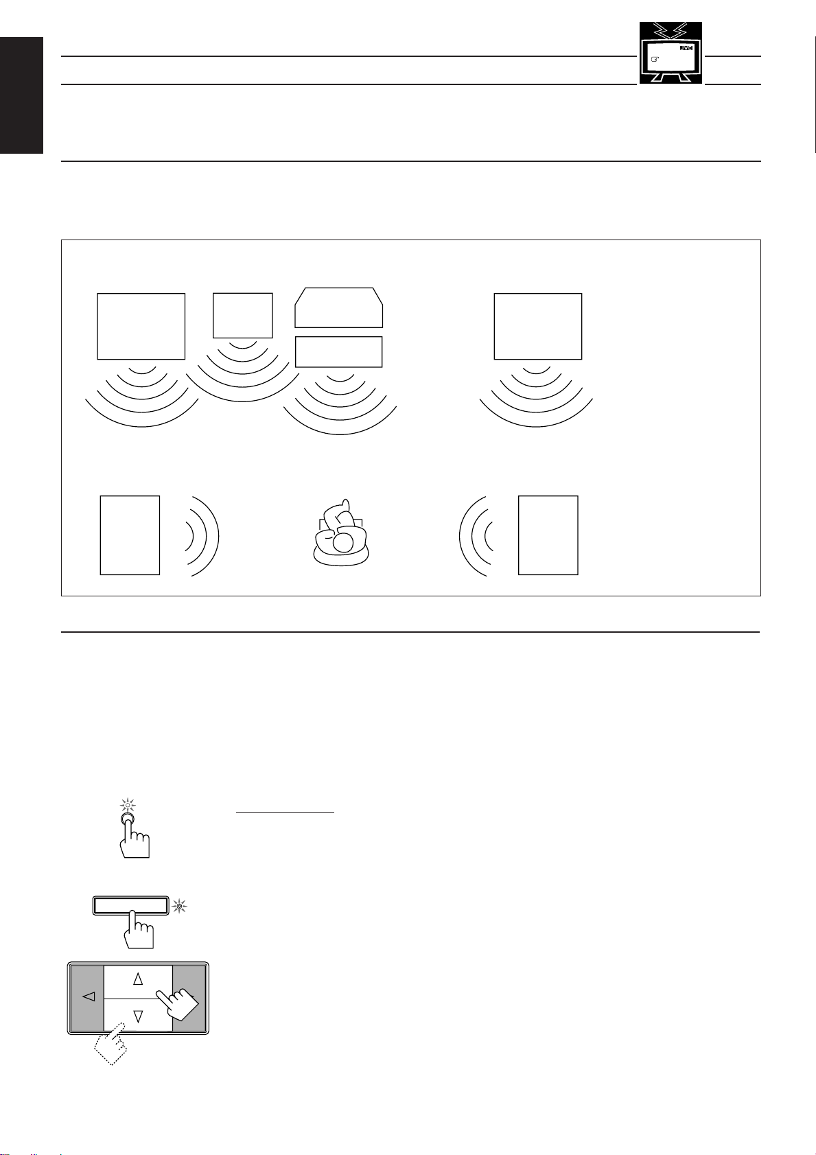
Speaker arrangements for DVD MULTI playback
When you play back a disc on the DVD player with its analog discrete output mode selected:
the DVD player.
Before playing back a DVD, refer also to the manual supplied with the DVD player.
The following illustrations show how to obtain the optimum sound environment for the DVD MULTI
playback mode. Try to find the speaker direction and location to create the optimum sound field.
See also
page 39.
MENU
Left front
woofer
speaker
Left rear
speaker
Activating the DVD MULTI playback
You can adjust the DVD MULTI playback mode while playing back a DVD using the analog discrete output
mode on the DVD player.
Once you made adjustments, the receiver memorizes the adjustments until you change them. You also need
to set the DVD player to the analog discrete output mode.
Sub-
TV
Center speaker
Right front
speaker
Right rear
speaker
Note:
You can place the subwoofer
anywhere around you.
Page 29
DAP/SURROUND/DVD MULTI
ADJUST
Front panel
Note:
When you select “DVDMULTI” as the source to play, the DAP and surround modes are canceled
temporarily.
On the front panel:
1. Press DVD MULTI so that “DVDMULTI” appears on the display.
The lamp above the button and the DVD lamp (of the source lamps) light up.
2. Select the analog discrete output mode on the DVD player, and start playing a DVD.
Refer to the manual supplied with the DVD player.
If you want to make any adjustment, go to the following steps.
3. Press DAP/SURROUND/DVD MULTI ADJUST so that the Control % / fi / @ / # buttons
work for adjusting the DVD MULTI playback mode.
The lamp next to the button lights up.
4. Press Control % / fi until “–CENTER+” appears on the display.
Page 33

5. Press Control @ / # to adjust the center speaker output level.
• Pressing Control @ decreases the output level up to –10 dB.
• Pressing Control # increases the output level up to +10 dB.
Front panel
6. Press Control % / fi until “–REAR L+” appears on the display.
7. Press Control @ / # to adjust the left rear speaker output level.
• Pressing Control @ decreases the output level up to –10 dB.
• Pressing Control # increases the output level up to +10 dB.
8. Press Control % / fi until “–REAR R+” appears on the display.
9. Press Control @ / # to adjust the right rear speaker output level.
• Pressing Control @ decreases the output level up to –10 dB.
• Pressing Control # increases the output level up to +10 dB.
10. Press Control % / fi until “CNT TONE” (Center Tone) appears on the display.
11. Press Control @ / # to select the center tone you want.
The center tone adjustment affects the mid-frequency range, which the human voice is mostly made
up of.
Each time you press the button, the display changes to show the following:
SHARP1 SHARP2FLATSOFT2 SOFT1
To make the dialogue clearer, select “SHARP1” (little) or “SHARP2” (much).
To make the dialogue softer, select “SOFT1” (little) or “SOFT2” (much).
When “FLAT” is selected, no adjustment is applied.
English
DVD
MULTI
TV / VCR / TUNER
/ CD / DVD / VCD
SOUND
CONTROL
CNTR
23
REAR (L)
ENTER
56
From the remote control:
Note:
If you want to use the remote control for adjusting the center tone, use the menu function (see page 39).
1. Press DVD MULTI so that “DVDMULTI” appears on the display.
The DVD MULTI lamp lights up and the DVD lamp (of the source lamps) lights up.
2. Select the analog discrete output mode on the DVD player, and start playing a DVD.
Refer to the manual supplied with the DVD player.
If you want to make any adjustment, go to the following steps.
3. Set the remote control mode selector to the “SOUND CONTROL” position.
10 keys are activated for adjusting the sounds.
4. Press CNTR +/– to adjust the center speaker output level.
• Pressing CNTR – decreases the output level up to –10 dB.
• Pressing CNTR + increases the output level up to +10 dB.
5. Press REAR•(L) +/– to adjust the left rear speaker output level.
• Pressing REAR•(L) – decreases the output level up to –10 dB.
• Pressing REAR•(L) + increases the output level up to +10 dB.
(REAR R)
89
Remote Control
6. Press (REAR•R) +/– to adjust the right rear speaker output level.
• Pressing (REAR•R) – decreases the output level up to –10 dB.
• Pressing (REAR•R) + increases the output level up to +10 dB.
Page 30
Page 34

Using the Surround Modes
English
Speaker arrangements for surround mode
CASE 1 When you have added a center speaker and rear speakers
See also
page 40.
MENU
With this receiver, you can use two types of the surround mode — Dolby Surround and JVC Theater Surround
The following illustrations show how to obtain the optimum sound environment for surround modes. Try to
find the speaker direction and location to create the optimum sound field.
Front
speaker
Rear
speaker
TV
Center speaker
Front
speaker
Rear
speaker
CASE 2 When you have added rear speakers (without a center speaker)
Front
speaker
Rear
speaker
TV
Front
speaker
Rear
speaker
In this case:
1.Select “PROLOGIC,”
“THEATER1” or
“THEATER2.”
2.Select “NORMAL” or
“WIDE” for center mode.
See pages 32 to 35 for more details.
In this case:
1.Select “PROLOGIC,”
“THEATER1” or
“THEATER2.”
2.Select “PHANTOM” for
center mode.
See pages 32 to 35 for more details.
CASE 3 When you have added a center speaker (without rear speakers)
Front
speaker
TV
Center speaker
Front
speaker
Page 31
In this case:
1.Select “3CHLOGIC.”
2.Select “NORMAL” or
“WIDE” for center mode.
See pages 32 to 35 for more details.
Page 35

Preparing for the surround mode
Once you have set the surround modes, you can use the same adjustment every time you want to activate the
surround you want. The receiver memorizes surround adjustments for each mode.
Note:
When you select “DVDMULTI” as the source to play, you cannot select or adjust the surround mode.
On the front panel:
DAP/SURROUND MODE
1. Press DAP/SURROUND MODE so that the Control % / fi / @ / # buttons work for selecting
2. Press Control @ / # to select the surround mode.
3. Press Control % / fi until the surround mode you want appears on the display.
English
the DAP/surround modes.
The lamp next to the button lights up.
The SURROUND indicator lights up on the display.
Each time you press the button, the DAP and surround modes alternately come into effect.
Each time you press the button, the surround modes change as follows (the indicator of the selected
surround mode also lights up on the display):
PROLOGIC 3CHLOGIC
Front panel
DAP/SURROUND/DVD MULTI
ADJUST
(Surround Off)
THEATER2SURR OFF
THEATER1
PROLOGIC: Select this mode to watch a video source with Dolby Surround when you have
connected the rear speakers (and a center speaker).
3CHLOGIC: Select this mode to watch a video source with Dolby Surround when you have
connected a center speaker and no rear speakers.
THEATER1: Select this mode to watch a video source with Dolby Surround when you have
connected the rear speakers (and a center speaker).
This mode gives you the feeling of a small movie theater with a seating capacity
of 100.
THEATER2: Select this mode to watch a video source with Dolby Surround when you have
connected the rear speakers (and a center speaker).
This mode gives you the feeling of a large movie theater with a seating capacity
of 1000.
SURR OFF: No surround mode is applied.
4. Press DAP/SURROUND/DVD MULTI ADJUST so that the Control % / fi / @ / # buttons work
for adjusting the surround mode.
The lamp next to the button lights up.
To be continued to the next page
Page 32
Page 36

English
Left front speaker
Center speaker
Rear speakers
Right front speaker
5. Press Control % / fi until “CNT MODE” (Center Mode) appears on the display.
6. Press Control @ / # to select the center mode.
Each time you press the button, the center modes change as follows:
WIDE
NORMAL
PHANTOM
OFF
WIDE: Select this mode when the center speaker can reproduce the bass better than the
front speakers. All signals of the center channel are output through the center
speaker.
NORMAL: Select this mode when the center speaker cannot reproduce the bass better than
the front speakers. The bass portions of the center channel signals are output
through the front speakers.
PHANTOM: Select this mode when you do not use a center speaker. The center speaker channel
signals are output through the front speakers.
OFF: Select this mode to turn off the center speaker channel.
Notes:
• If you have already set the “center speaker size” following the procedure described on page 17, you do not
have to select the center mode in this procedure.
• When you have selected “3CHLOGIC,” you cannot select “PHANTOM.”
7. Press Control % / fi until “–DELAY +” appears on the display.
8. Press Control @ / # to adjust the delay time of the rear speaker output.
Each time you press the button, the delay time changes as follows:
DELAY 1
DELAY 4
DELAY 1: Select this when the distance from you to your rear speakers is greater than that
to the front speakers.
DELAY 2: Select this when the distance from you to your rear speakers is almost equal to
that to the front speakers.
DELAY 3: Select this when the distance from you to your rear speakers is a little less than
that to the front speakers.
DELAY 4: Select this when the distance from you to your rear speakers is much less than
that to the front speakers.
Note:
When you have selected “3CHLOGIC,” you cannot adjust the delay time.
9. Press Control % / fi until “TEST” appears on the display, then press Control @ / # to start
checking the speaker output balance.
“TEST” starts flashing on the display, and a test tone comes out of the speakers in the following
order:
DELAY 2
DELAY 3
Front panel
Page 33
Notes:
• No test tone comes out of the rear speakers when you have selected “3CHLOGIC.”
• No test tone comes out of the center speaker when you select “PHANTOM” or “OFF” for the center
mode.
Page 37

10. If necessary, adjust the speaker output level as follows:
EFFECT 1 EFFECT 2
EFFECT 4
EFFECT 3
EFFECT 5
• To adjust the rear speaker output level, press Control % / fi until “– REAR +” appears on the
display, then press Control @ / #.
• To adjust the center speaker output level, press Control % / fi until “–CENTER+” appears on the
display, then press Control @ / #.
Notes:
• You cannot adjust the left and right rear speaker output level separately.
• You cannot adjust the rear speaker output level when you have selected “3CHLOGIC.”
• You cannot adjust the center speaker output level when you select “PHANTOM” or “OFF” for the
center mode.
11. Press Control % / fi until “TEST” appears on the display, then press Control @ / # to stop the
test tone.
12. Press Control % / fi until “CNT TONE” (Center Tone) appears on the display.
English
Front panel
13. Press Control @ / # to select the center tone you want.
The center tone adjustment affects the mid-frequency range, which the human voice is mostly made
up of.
Each time you press the button, the display changes to show the following:
SHARP1 SHARP2FLATSOFT2 SOFT1
To make the dialogue clearer, select “SHARP1” (little) or “SHARP2” (much).
To make the dialogue softer, select “SOFT1” (little) or “SOFT2” (much).
When “FLAT” is selected, no adjustment is applied.
Note:
The center tone cannot be adjusted when sounds do not come out of the center speaker.
If you have selected the JVC Theater Surround, go to the following steps.
14. Press Control % / fi until “–EFFECT+” appears on the display.
15. Press Control @ / # to adjust the effect level.
Each time you press the button, the effect level changes as follows:
As the number increases, the surround mode becomes stronger.
Note:
When you have selected Dolby Surround, you cannot select the effect level.
Page 34
Page 38

English
Left front speaker
Center speaker
Rear speakers
Right front speaker
EFFECT 1 EFFECT 2
EFFECT 4
EFFECT 3
EFFECT 5
PROLOGIC 3CHLOGIC
THEATER1
THEATER2SURR OFF
(Surround Off)
DELAY 1
DELAY 2
DELAY 4
DELAY 3
From the remote control:
Note:
If you want to use the remote control for adjusting the center mode and the center tone, use the menu function
(see page 40).
TV / VCR / TUNER
/ CD / DVD / VCD
SOUND
CONTROL
SURR MODE
+10
DELAY
MENU
1
TEST
4
1. Set the remote control mode selector to the “SOUND CONTROL” position.
10 keys are activated for adjusting the sounds.
2. Press SURR MODE until the surround mode you want appears on the display.
The SURROUND indicator also lights up on the display.
Each time you press the button, the surround modes change as follows (the indicator of the selected
surround mode also lights up on the display):
3. Press DELAY to adjust the delay time of the rear speaker output.
Each time you press the button, the delay time changes as follows:
Note:
When you have selected “3CHLOGIC,” you cannot adjust the delay time.
4. Press TEST to start checking the speaker output balance.
“TEST” starts flashing on the display, and a test tone comes out of the speakers in the following
order:
CNTR
ENTER
23
TEST
4
EFFECT
7/P
REAR (L)
56
Notes:
• No test tone comes out of the rear speakers when you have selected “3CHLOGIC.”
• No test tone comes out of the center speaker when you select “PHANTOM” or “OFF” for the center
mode.
5. If necessary, adjust the speaker output level as follows:
• To adjust the rear speaker output level, press REAR•(L) +/–.
• To adjust the center speaker output level, press CNTR +/–.
Pressing – decreases the output level up to –10 dB.
Pressing + increases the output level up to +10 dB.
Notes:
• You cannot adjust the left and right rear speaker output level separately.
• You cannot adjust the rear speaker output level when you have selected “3CHLOGIC.”
• You cannot adjust the center speaker output level when you select “PHANTOM” or “OFF” for the
center mode.
6. Press TEST again to stop the test tone.
If you have selected the JVC Theater Surround, go to the following steps.
7. Press EFFECT to adjust the effect level.
Each time you press the button, the effect level changes as follows:
Remote Control
Page 35
As the number increases, the surround mode becomes stronger.
Note:
When you have selected Dolby Surround, you cannot select the effect level.
Page 39

Activating the surround modes
DAP/SURROUND MODE
Once you have set the surround modes, you can use the same adjustment every time you want to enjoy the
surround you want. The receiver memorizes surround adjustments for each mode.
English
Note:
When you select “DVDMULTI” as the source to play, the surround mode is canceled temporarily.
On the front panel:
1. Press DAP/SURROUND MODE so that the Control % / fi / @ / # buttons work for selecting
the DAP/surround modes.
The lamp next to the button lights up.
2. Press Control @ / # to select the surround mode.
The SURROUND indicator lights up on the display.
Each time you press the button, the DAP and surround modes alternately come into effect.
3. Press Control % / fi until the surround mode you want appears on the display.
Each time you press the button, the surround modes change as follows (the indicator of the selected
surround mode also lights up on the display):
PROLOGIC 3CHLOGIC
Front panel
TV / VCR / TUNER
/ CD / DVD / VCD
SOUND
CONTROL
SURR MODE
+10
Remote Control
(Surround Off)
THEATER2SURR OFF
THEATER1
4. Select and play a sound source which was processed with Dolby Surround and is labeled with
DOLBY SURROUND
mark.
To cancel the surround mode, press Control % / fi until “SURR OFF” appears in step 3 above.
The SURROUND indicator and the indicator of the selected surround mode goes off from the display.
From the remote control:
1. Set the remote control mode selector to the “SOUND CONTROL” position.
10 keys are activated for adjusting the sounds.
2. Press SURR MODE until the surround mode you want appears on the display.
The SURROUND indicator also lights up on the display.
Each time you press the button, the surround modes change as follows (the indicator of the selected
surround mode also lights up on the display):
PROLOGIC 3CHLOGIC
(Surround Off)
THEATER2SURR OFF
3. Select and play a sound source which was processed with Dolby Surround and is labeled with
DOLBY SURROUND
mark.
THEATER1
To cancel the surround mode, press SURR MODE until “SURR OFF” appears in step 2 above.
The SURROUND indicator and the indicator of the selected surround mode goes off from the display.
Page 36
Page 40

Using the On-Screen Display to Control the Receiver
You can use the menu function on the TV screen to control the receiver.
English
Basic Procedures
Menu function buttons
CONTROL
TAPE VCR
MENU
EXIT
MENU
SET
To use this function, you need to connect the TV to the MONITOR OUT jack on the rear panel (see page 9),
and set the TV’s input mode to the appropriate position to which the receiver is connected.
When the TV’s input mode is for TV, you cannot see the on-screen display.
IMPORTANT
When you use the menu functions, make sure that you have connected a TV and operate the
menu function while watching the on-screen displays on the TV.
Note:
If your TV is not of the PAL color system, the TV screen will be distorted.
From the remote control:
1. Press MENU SET.
The MAIN MENU appears on the TV screen.
• If you press % / fi / @ / #, a sub-menu you can adjust at that time appears on the TV
screen instead of the MAIN MENU.
2. Press % / fi to move
The sub-menu you want appears.
O
N
S
C
R
E
L
O
R
T
N
E
O
N
C
3. If necessary, press % / fi / @ / # to set or adjust the item you want on the selected submenu.
When a item is selected, the item will be highlighted.
MAIN MENU
Note:
Moving
press
@
/ # to highlight it.
4. When you finish, press MENU EXIT.
The menu disappears from the TV.
To go back to the MAIN MENU any time during the process
Press MENU SET again.
Shows the buttons you can use on the current menu. In
this case, press % / fi to move
up and down, and @
/ # to select the item.
Selecting the Source to Play (Also see page 12)
1. Press MENU SET.
The MAIN MENU appears on the TV.
2. Press % / fi to move
The SOURCE menu appears.
to “SOURCE,” then press @ / #.
to the sub-menu you want to set, then press @ / # .
to an item does not mean that you have selected it. If the item is not highlighted,
SOURCE menu
3. Press % / fi to move
to the source you want to play.
To select the DVD MULTI playback mode, press @ / # while “DVD” is selected as the
source.
4. When you finish, press MENU EXIT.
The menu disappears from the TV.
Adjusting the Front Speaker Output Balance (Also see page 15)
1. Press MENU SET.
The MAIN MENU appears on the TV.
2. Press % / fi to move
to “SETTING,” then press @ / #.
The SETTING menu appears.
3. Press % / fi to move
to “BAL. ” (Balance).
4. Press @ / # repeatedly to adjust the balance.
5. When you finish, press MENU EXIT.
The menu disappears from the TV.
Page 37
SETTING menu
Shows the buttons you can use on
the current menu.
In this case, press % / fi to move
up and down, and @ / # to
adjust or set the item.
Page 41

Listening at Low Volume (Loudness) (Also see page 15)
1. Press MENU SET.
The MAIN MENU appears on the TV.
2. Press % / fi to move
The SETTING menu appears.
to “SETTING,” then press @ / #.
English
SETTING menu
3. Press % / fi to move
4. Press @ / # to set the loudness function to “ON” or “OFF.”
5. When you finish, press MENU EXIT.
The menu disappears from the TV.
to “LOUDNESS.”
Using the Sleep Timer (Also see page 16)
1. Press MENU SET.
The MAIN MENU appears on the TV.
2. Press % / fi to move
The SETTING menu appears.
3. Press % / fi to move
4. Press @ / # to set the shut-off time.
5. When you finish, press MENU EXIT.
The menu disappears from the TV.
to “SETTING,” then press @ / #.
to “SLEEP TIMER.”
Selecting the Center Speaker Size (Also see page 17)
Note:
When the surround mode is off, you cannot select the center speaker size.
SETTING menu
1. Press MENU SET.
The MAIN MENU appears on the TV.
2. Press % / fi to move
The SETTING menu appears.
3. Press % / fi to move
4. Press @ / # repeatedly until the appropriate center speaker size is selected.
5. When you finish, press MENU EXIT.
The menu disappears from the TV.
to “SETTING,” then press @ / #.
to “CENTER SPK” (Center Speaker).
Using Visual Confirmation (Also see page 18)
1. Press MENU SET.
The MAIN MENU appears on the TV.
2. Press % / fi to move to “SETTING,” then press @ / #.
The SETTING menu appears.
3. Press % / fi to move
4. Press @ / # to set Visual Confirmation to “ON” or “OFF.”
5. When you finish, press MENU EXIT.
The menu disappears from the TV.
to “VISUAL CONFIRM.” (Visual Confirmation).
SETTING menu
SETTING menu
Page 38
Page 42

Operating the Tuner
1. Press MENU SET.
The MAIN MENU appears on the TV.
English
2. Press % / fi to move
The TUNER menu appears.
to “TUNER,” then press @ / #.
TUNER menu
3. Press % / fi to move
On the TUNER menu, you can do the following:
“CH.”: Select a preset channel station. (See page 21)
“BAND”: Select the band. (See page 20)
“TUNING”: Tune in a station manually. (See page 20)
“FM MODE”: Select the FM reception mode. (See page 22)
4. When you finish, press MENU EXIT.
The menu disappears from the TV.
to the item you want to set or adjust, then press @ / #.
If you want to assign a name to a preset channel, see page 23.
Selecting Your Favorite SEA Mode (Also see page 24)
1. Press MENU SET.
The MAIN MENU appears on the TV.
2. Press % / fi to move
The SEA MODE menu appears.
3. Press % / fi to move
4. When you finish, press MENU EXIT.
The menu disappears from the TV.
to “SEA,” then press @ / #.
to the SEA mode you want.
Creating Your Own SEA Mode (Also see page 25)
1. Press MENU SET.
The MAIN MENU appears on the TV.
If you have assigned the
name to this preset station, it
appears here.
SEA MODE menu
2. Press % / fi to move
The SEA ADJUST menu appears.
3. Press % / fi / @ / # to adjust the SEA mode as you want.
@ / #: Select the frequency ranges.
% / fi: Adjust the frequency levels.
4. Press MEMORY (next to the SEA ADJUST button).
5. When you finish, press MENU EXIT.
The menu disappears from the TV.
to “SEA ADJUST” then press @ / #.
Adjusting the DVD MULTI Playback Mode (Also see page 29)
Before adjusting the DVD MULTI playback mode, you have to select “DVDMULTI” as the source to play.
1. Press MENU SET.
The MAIN MENU appears on the TV.
2. Press % / fi to move
The DVD MULTI menu appears.
3. Press % / fi to move
On the DVD MULTI adjustment menu, you can do the following:
“CENTER”: Adjust the center speaker output level.
“REAR L”: Adjust the left rear speaker output level.
“REAR R”: Adjust the right rear speaker output level.
“CENTER TONE”: Select the center tone.
to “DVD/SURR/DAP ADJUST,” then press @ / #.
to the item you want to set or adjust, then press @ / #.
SEA ADJUST menu
DVD MULTI adjustment menu
4. When you finish, press MENU EXIT.
The menu disappears from the TV.
Page 39
Page 43

Selecting the DAP or Surround Modes (Also see pages 27 and 31)
Note:
When the source is “DVDMULTI”, you cannot select the DAP or the surround mode.
1. Press MENU SET.
The MAIN MENU appears on the TV.
English
DAP MODE menu
2. Press % / fi to move
The DAP or SURROUND menu (previously selected mode) appears.
3. Press @ / # to select either the surround or DAP mode.
The DAP MODE menu or SURROUND MODE menu appears.
4. Press % / fi to move
If you want to adjust the selected mode, go to the following steps.
5. Press MENU SET.
The MAIN MENU appears on the TV again.
6. Press % / fi to move
The adjustment menu for the mode you have selected in step 4 appears.
7. Press % / fi to move
On these adjustment menus, you can do the following:
For Dolby Pro Logic:
“CENTER MODE”: Select the center mode.
“TEST”: Output a test tone.
“CENTER”: Adjust the center speaker output level.
“REAR”: Adjust the rear speaker output level.
“DELAY”: Adjust the delay time of the rear speaker sound.
“CENTER TONE”: Select the center tone.
to “SURR/DAP,” then press @ / #.
to one of the DAP modes or surround modes.
to “DVD/SURR/DAP ADJUST,” then press @ / #.
to the item you want to set or adjust, then press @ / #.
SURROUND MODE menu
PRO LOGIC adjustment menu
3CH LOGIC adjustment menu
For Dolby 3ch Logic:
“CENTER MODE”: Select the center mode.
“TEST”: Output a test tone.
“CENTER”: Adjust the center speaker output level.
“CENTER TONE”: Select the center tone.
For JVC Theater Surround:
“CENTER MODE”: Select the center mode.
“TEST”: Output a test tone.
“CENTER”: Adjust the center speaker output level.
“REAR”: Adjust the rear speaker output level.
“DELAY”: Adjust the delay time of the rear speaker sound.
“CENTER TONE”: Select the center tone.
“EFFECT”: Adjust the effect level.
For DAP modes:
“REAR”: Adjust the rear speaker output level. (This cannot be adjusted for
“Headphones.”)
“EFFECT”: Adjust the effect level.
8. When you finish, press MENU EXIT.
The menu disappears from the TV.
Theater Surround adjustment
menu (eg. THEATER-1)
DAP mode adjustment menu
(eg. DANCE CLUB)
Page 40
Page 44

COMPU LINK Remote Control System
The COMPU LINK remote control system allows you to operate JVC audio components through the remote
English
sensor on the receiver.
To use this remote control system, you need to connect JVC audio components through the COMPU LINK3 (SYNCHRO) jacks (see below) in addition to the connections using cables with RCA pin plugs (see page
8).
CD player
Notes:
• If your audio component has two COMPU LINK-3 (SYNCHRO) jacks, you can use either one. If it has only
one COMPU LINK-3 (SYNCHRO) jack, connect it so that it is the last item in the series of components. (For
example, the turntable or CD player in the diagram above.)
• Refer also to the manuals supplied with your audio components.
This remote control system allows you to use four functions listed below.
7 Remote Control through the Remote Sensor on the Receiver
You can control the connected audio components through the remote sensor on the receiver using this remote
control. For details, see pages 44 and 45.
Note:
Aim the remote control directly at the remote sensor on the receiver.
7 Automatic Source Selection
When you press the play (
automatically turns on and changes the source to the component. On the other hand, if you select a new source
on the receiver or the remote control, the selected component begins playing immediately.
In both cases, the previously selected source continues playing without sound for a few seconds.
33
3) button on a connected component or on its own remote control, the receiver
33
Cassette deck
COMPU LINK – 3
(SYNCHRO)
Turntable
Page 41
7 Automatic Power On/Off (only possible with the COMPU LINK-3 connection)
Both the CD player and cassette deck turn on and off along with the receiver.
When you turn on the receiver, the CD player or cassette deck will turn on automatically, depending on which
component has been previously selected.
When you turn off the receiver, both the CD player and cassette deck will turn off.
7 Synchronized Recording
Synchronized recording means the cassette deck starts recording as soon as a CD or a record begins playing.
To use synchronized recording, follow these steps:
1 Put a tape in the cassette deck, and a disc in the CD player (or a record on the turntable).
2 Press the record (
This puts the cassette deck into recording pause.
Note:
If you do not press the record (¶) button and pause (8) button at the same time, the synchronized recording
feature will not operate.
3 Press the play (
The source changes on the receiver, and as soon as play starts, the cassette deck starts recording.
When the play ends, the cassette deck enters recording pause, and stops about 4 seconds later.
Notes:
• During synchronized recording, the selected source cannot be changed.
• If your CD player is playing in program mode, a 4-second blank is recorded between tracks so that the music
scan feature of your cassette deck can be used on the recorded tape.
• If the power of any component is shut off during synchronized recording, the COMPU LINK remote control
system may not operate properly. In this case, you must start again from the beginning.
¶¶
¶) button and the pause (
¶¶
33
3) button on the CD player or on the turntable.
33
88
8) button on the cassette deck at the same time.
88
Page 45

AV COMPU LINK Remote Control System
The AV COMPU LINK remote control system allows you to operate JVC video components (TV, VCR, and
DVD player) through the receiver.
CONNECTIONS:
To use this remote control system, you need to connect the video components you want to operate, following
the procedures below.
CAUTION:
The AV COMPU LINK remote control system cannot control the video components connected
to the VIDEO1, VIDEO2, and TAPE/VCR jacks on the receiver. Use only VCR1 jacks for the
VCR and the DVD jacks for the DVD player.
1. Connect your VCR, DVD player, and TV as follows, using the AV COMPU LINK cable (only
one cable is supplied with this receiver).
VCR
VHS
Note:
You can use one of the AV COMPU LINK jacks to connect the video components.
2. Connect the audio input/output jacks of the VCR, DVD player, and TV as follows using the
cables with RCA pin plug. See page 9.
DVD player
English
TV
AV
COMPU LINK
DVD
3. Connect the video input/output jack of the VCR, DVD player, and TV as follows.
CASE 1: If all the components are equipped with the S-
video terminals.
DO NOT use these
video terminals.
OUT
To Video Input 2
To Video Input 1
S-VHS VCR
S-VHS
TV
DEO1
TV
UND
UT
EC)
CR1
IN
LAY)
VIDEO
MONITOR
DVD player
DVD
DVD
CASE 3: If the VCR is equipped with the S-video
terminals, but the DVD player is not.
DO NOT use these
video terminals.
CASE 2: If all the components are not equipped with the
S-video terminals.
DO NOT use these
video terminals.
VIDEO
IDEO1
TV
UND
UT
EC)
CR1
IN
LAY)
MONITOR
OUT
To Video Input 2
VHS VCR
VHS
TV
DVD player
DVD
DVD
CASE 4: If the DVD player is equipped with the S-video
terminals, but the VCR is not.
DO NOT use these
video terminals.
IDEO1
TV
OUND
OUT
REC)
VCR1
IN
PLAY)
VIDEO
MONITOR
OUT
DVD
To Video Input 2
S-VHS VCR
S-VHS
DVD player
VIDEO
TVTo Video Input 1
DVD
VIDEO1
TV
SOUND
OUT
(REC)
VCR1
IN
(PLAY)
MONITOR
To Video Input 2
OUT
DVD
TVTo Video Input 1
VHS VCR
VHS
DVD player
DVD
4. When turning on the TV for the first time after the AV COMPU LINK connection, turn the TV
volume to the minimum using the TV volume control on the TV.
Page 42
Page 46

English
FUNCTIONS:
This remote control system allows you to use five functions listed below.
Note:
Refer also to the manuals supplied with your video components.
7 Remote Control of the TV through the Remote Sensor on the Receiver
You can control the TV through the remote sensor on the receiver using this remote control.
For details, see page 47.
Note:
Aim the remote control directly at the remote sensor on the receiver when operating the TV. (However, to
operate the VCR or DVD player, always aim the remote control directly at the remote sensor on the VCR or
on the DVD player.)
7 One-Touch Video Play
Simply by inserting a video cassette without its safety tab into the VCR1 (the VCR connected to the VCR1
jacks), you can enjoy the video playback without setting other switches manually.
The receiver automatically turns on and changes the source to “VCR1.”
The TV automatically turns on and changes the input mode to the position you can view the VCR playback.
When you insert a video cassette with its safety tab, press the play (
control. So, you can get the same result.
Note:
When you connect an S-VHS VCR or the DVD player as described on page 42, you cannot see the on-screen
displays (such as Visual Confirmation and Menus) since the AV COMPU LINK Remote Control System
automatically changes the TV input mode to “Video input 1” when you operate the S-VHS VCR or the DVD
player.
If you do not mind stopping watching the picture, you can then show the on-screen displays after changing
the TV input mode to the position (Video input 2) the receiver is connected to.
33
3) button on the VCR1 or on the remote
33
7 One-Touch DVD Play
Simply by starting playback on the DVD player, you can enjoy the DVD playback without setting other
switches manually.
The receiver automatically turns on and changes the source to “DVD” or “DVDMULTI” — DVD playback
mode is automatically selected when a disc played in stereo or the audio output setting of the DVD player is
mixed to two front channels, while DVD MULTI playback mode is automatically selected when a disc played
back using the analog discrete output mode on the DVD player.
The TV automatically turns on and changes the input mode to the position so that you can view the playback
picture.
7 Automatic Selection of TV’s Input Mode
• When you select “TV SOUND” as the source to play on the receiver, the TV automatically changes the input
mode to the TV tuner so that you can watch TV.
• When you select “VIDEO1,” “VIDEO2,” or “TAPE/VCR” as the source to play on the receiver, the TV
automatically changes the input mode to the Video Input 2 so that you can watch the playback picture.
• When you select “DVD,” “DVDMULTI,” or “VCR1” as the source to play on the receiver, the TV
automatically changes the input mode to the correct position (either Video Input 1 or 2) so that you can watch
the playback picture.
Note:
When you select “TV SOUND” as the source on the receiver, you cannot see the on-screen displays (such as
Visual Confirmation and the menu function) since the AV COMPU LINK remote control system automatically
changes the TV input mode to the TV tuner.
If you do not mind stopping listening to the TV sounds, you can then show the on-screen displays after changing
the TV input mode to the position (Video input 2) the receiver is connected to.
7 Automatic Power On/Off
The TV, VCR1 (the VCR connected to the VCR1 jacks), and DVD player turn on and off along with the
receiver.
When you turn on the receiver;
• If the previously selected source is “VCR1”, the TV and VCR1 will turn on automatically.
• If the previously selected source is “VIDEO1,” “VIDEO2,” or “TV SOUND,” only the TV will turn on
automatically.
• If the previously selected source is “DVD” or “DVDMULTI,” the TV and DVD player will turn on
automatically.
When you turn off the receiver, the TV, VCR1 and DVD player will turn off.
Page 43
Note:
If you turn off the receiver while recording on the VCR1, the VCR1 will not turn off, but continue recording.
Page 47
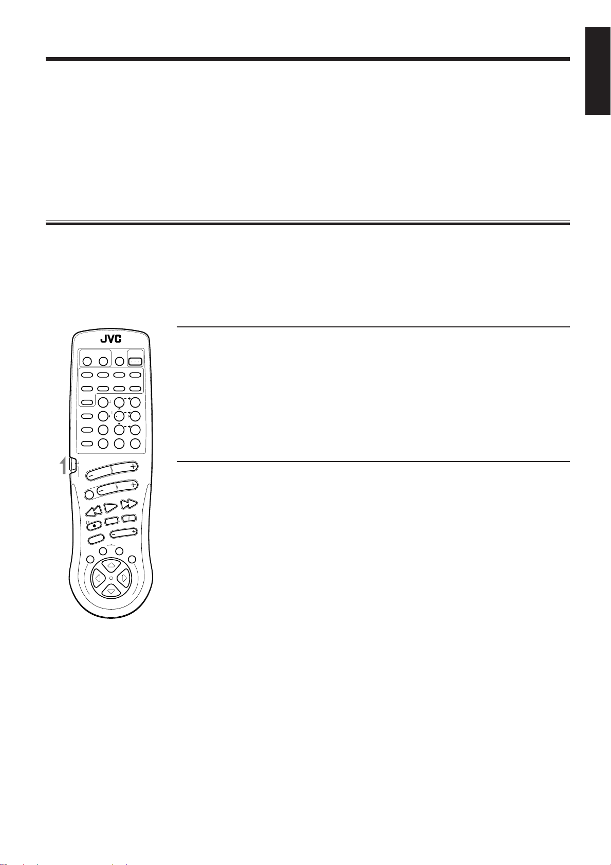
Using the Remote Control for Operating JVC’s Audio/Video Components
O
N
S
C
R
E
E
N
C
O
N
T
R
O
L
RM-SR80U REMOTE CONTROL
CD
DISC
VCD
DISC
VCD
CONTROL
VCR
POWER
TV
POWER
AUDIO
POWER
DVD
MULTI
VIDEO1 VIDEO2
TAPE/VCR
VCR1
TV
SOUND
DVD
TEST
(REAR R)
REAR (L)
SEA MODE DAP MODE SURR MODE
FM/AM PHONOCD
546
213
87
/P
9
0
+10
10
TV / VCR / TUNER
/ CD / DVD / VCD
MENU
EXIT
MENU
SET
TAPE VCR
CONTROL
VOLUME
CHANNEL
MUTING
FF / ¢
NEXT /
PLAY
SELECT /
STOP
/ REC
TV/VIDEO
TV VOLUME
PAUSE
4 / REW
PREV /
CNTRDELAY
MENU
ENTER
EFFECT
SOUND
CONTROL
FM MODE/MUTINGRETURN
You can operate JVC’s audio and video components with this receiver’s remote control, since control signals
for JVC components are preset in the remote control.
Notes:
• If you use the buttons on the front panel or the menu function to choose a source, the remote control will
not operate that source. To operate a source with the remote control, the source must be selected using
buttons on the remote control.
• Check to see if its remote control mode selector is set to the correct position.
Normally, set it to the “TV / VCR / TUNER / CD / DVD / VCD” position.
To activate the 10 keys for adjusting the sound, set it to the “SOUND CONTROL” position.
• Refer also to the manuals supplied with your components.
IMPORTANT
To operate JVC’s audio components using this remote control:
• You need to connect JVC audio components through the COMPU LINK-3 (SYNCHRO) jacks
(see page 41) in addition to the connections using cables with RCA pin plugs (see page 8).
• Aim the remote control directly at the remote sensor on the receiver.
Tuner
After pressing FM/AM (with the remote control mode selector set to the “TV / VCR / TUNER / CD / DVD /
VCD” position), you can perform the following operations:
FM/AM: Alternates between FM and AM.
1 — 10, +10: Selects a preset channel number directly.
For channel number 5, press 5. For channel number 15, press +10, then 5. For
channel number 20, press +10, then 10.
FM MODE/MUTING: Changes the FM reception mode.
English
Sound control section (Amplifier)
With the remote control mode selector set to the “SOUND CONTROL” position, you can perform the
following operations:
SEA MODE: Changes the SEA modes.
DAP MODE: Changes the DAP modes.
SURR MODE: Changes the surround modes.
CNTR +/–: Changes the center speaker output level for the DVD MULTI playback and surround
modes.
REAR•(L) +/–: Changes the left/right rear speaker output level for DAP and surround modes.
Changes the left rear speaker output level for the DVD MULTI playback mode.
(REAR•R) +/–: Changes the right rear speaker output level for the DVD MULTI playback mode.
EFFECT: Changes the effect level for DAP and surround modes.
DELAY: Changes the delay time for surround modes.
TEST: Checks the speaker output level for surround modes.
Note:
After adjusting sounds, set the remote control mode selector to the “TV / VCR / TUNER / CD / DVD / VCD”
position to operate your target source by using 10 keys; otherwise, 10 keys cannot be used for operating your
target source.
Page 44
Page 48

English
RM-SR80U REMOTE CONTROL
VCR
TV
POWER
POWER
VIDEO1 VIDEO2
TV
SOUND
FM/AM PHONOCD
DVD
CD
TEST
DISC
VCD
EFFECT
DISC
/P
VCD
SEA MODE DAP MODE SURR MODE
CONTROL
10
TV / VCR / TUNER
/ CD / DVD / VCD
VOLUME
SOUND
CONTROL
MUTING
SELECT /
PLAY
PREV /
4 / REW
/ REC
TV/VIDEO
CONTROL
TAPE VCR
MENU
EXIT
O
N
S
C
R
E
AUDIO
DVD
POWER
MULTI
TAPE/VCR
VCR1
CNTRDELAY
MENU
213
REAR (L)
ENTER
546
(REAR R)
87
9
+10
0
FM MODE/MUTINGRETURN
CHANNEL
NEXT /
FF / ¢
PAUSE
STOP
TV VOLUME
MENU
SET
L
O
R
T
N
O
E
C
N
CD player
After pressing CD (with the remote control mode selector set to the “TV / VCR / TUNER / CD / DVD / VCD”
position), you can perform the following operations on a CD player:
PLAY: Starts playing.
44
4: Returns to the beginning of the current (or previous) track.
44
¢¢
¢: Skips to the beginning of the next track.
¢¢
STOP: Stops playing.
PAUSE: Pauses playing. To release it, press PLAY.
1 — 10, +10: Selects a track number directly.
To select track number 5, press 5. For track number 15, press +10, then 5. For track number 20,
press +10, then 10. For track number 30, press +10, +10, then 10.
CD player-changer
After pressing CD DISC (with the remote control mode selector set to the “TV / VCR / TUNER / CD / DVD
/ VCD” position), you can perform the following operations on a CD player-changer:
PLAY: Starts playing.
44
4: Returns to the beginning of the current (or previous) track.
44
¢¢
¢: Skips to the beginning of the next track.
¢¢
STOP: Stops playing.
PAUSE: Pauses playing. To release it, press the PLAY button.
1 — 6, 7/P: Select the number of a disc installed in a CD player-changer.
Turntable
After pressing PHONO (with the remote control mode selector set to the “TV / VCR / TUNER / CD / DVD
/ VCD” position), you can perform the following operations on a turntable:
PLAY: Starts playing.
STOP: Stops playing.
Cassette deck
After pressing TAPE/VCR or TAPE CONTROL (with the remote control mode selector set to the “TV / VCR
/ TUNER / CD / DVD / VCD” position), you can perform the following operations on a cassette deck:
PLAY: Starts playing.
REW: First rewinds the tape from right to left.
FF: First rewinds the tape from left to right.
STOP: Stops operations.
PAUSE: Pauses playing or recording temporarily. To release it, press the PLAY button.
¶¶
REC
¶: Press this button with the PLAY button to start recording.
¶¶
Press this button with the PAUSE button to enter recording pause (standby).
Note:
You can use either the TAPE/VCR button or the TAPE CONTROL button to activate the buttons listed above.
If you press TAPE/VCR, the playing source also changes to “TAPE/VCR.” On the other hand, if you press
TAPE CONTROL, the playing source does not change to “TAPE/VCR.”
Page 45
Page 49

IMPORTANT
To operate JVC’s video components using this remote control:
• Some JVC VCR can accept two types of the control signals — remote code “A” and “B.” Before
using this remote control, make sure that the remote control code of the VCR connected to the
VCR1 jacks is set to code “A.”
• When operating the video components, aim the remote control directly at the remote sensor
on the each component.
• When the TV is connected with the AV COMPU LINK cable (see page 42) in addition to the
connections using cables with RCA pin plugs (see pages 9 and 42), aim the remote control
directly at the remote sensor on the receiver to operate the TV.
VCR
After pressing VCR1 or VCR CONTROL (with the remote control mode selector set to the “TV / VCR /
TUNER / CD / DVD / VCD” position), you can perform the following operations on the VCR:
PLAY: Starts playing.
REW: Rewinds a tape.
FF: Fast winds a tape.
STOP: Stops operations.
PAUSE: Pauses playing or recording temporarily. To release it, press the PLAY button.
¶¶
REC
¶: Press this button with the PLAY button to start recording.
¶¶
Press this button with the PAUSE button to enter recording pause (standby).
CHANNEL +/–: Changes the channels on the VCR.
1 — 9, 0: Selects the channels on the VCR.
English
Notes:
• You can use either the VCR1 button or the VCR CONTROL button to activate the buttons listed above. If
you press VCR1, the playing source also changes to “VCR1.” On the other hand, if you press VCR
CONTROL, the playing source does not change to “VCR1.”
• You can also turn the VCR on and off by pressing VCR POWER on the remote control.
DVD player
After pressing DVD or DVD MULTI (with the remote control mode selector set to the “TV / VCR / TUNER
/ CD / DVD / VCD” position), you can perform the following operations on a DVD player:
PLAY: Starts playing.
44
4: Returns to the beginning of the current (or previous) track.
44
¢¢
¢: Skips to the beginning of the next track.
¢¢
STOP: Stops playing.
PAUSE: Stops playing temporarily. To release it, press the PLAY button.
After pressing DVD or DVD MULTI (with the remote control mode selector set to the “TV / VCR /
TUNER / CD / DVD / VCD” position), these buttons can be used for the DVD menu operations.
TEST
EFFECT
MENU
ENTER
CNTRDELAY
213
REAR (L)
546
(REAR R)
87/P 9
Note:
For detailed menu operations, refer to the instructions
supplied with the discs or the DVD player.
Page 46
Page 50

English
Video CD player
After pressing VCD DISC or VCD CONTROL (with the remote control mode selector set to the “TV / VCR
/ TUNER / CD / DVD / VCD” position) while playing back a Video CD player, you can perform the following
operations:
PLAY: Starts playing.
44
4: Returns to the beginning of the current (or previous) track.
44
¢¢
¢: Skips to the beginning of the next track.
¢¢
STOP: Stops playing.
PAUSE: Stops playing temporarily. To release it, press the PLAY button.
After pressing VCD DISC (with the remote control mode selector set to the “TV / VCR / TUNER / CD / DVD
/ VCD” position) while playing back a Video CD player, you can also perform the following operation:
1 — 7/P: Select the number of a disc installed in a CD player-changer.
After pressing VCD CONTROL (with the remote control mode selector set to the “TV / VCR / TUNER / CD
/ DVD / VCD” position) while playing back a Video CD player, you can also perform the following operation:
1 — 10, +10: Selects a track number directly.
To select track number 5, press 5. For track number 15, press +10, then 5. For track number 20,
press +10, then 10. For track number 30, press +10, +10, then 10.
After pressing VCD DISC or VCD CONTROL (with the remote control mode selector set to the “TV / VCR
/ TUNER / CD / DVD / VCD” position) while showing the Video CD player (with the PBC function) menu,
you can perform the following menu operations.
PREV: Views the previously shown portion of the menu.
SELECT: Confirms the currently shown portion of the menu.
NEXT: Views the unshown portion (continuation) of the menu.
: Goes back to the previous screen.
Note:
For detailed menu operations, refer to the instructions supplied with the discs or the Video CD player.
TV
After pressing TV SOUND (with the remote control mode selector set to the “TV / VCR / TUNER / CD / DVD
/ VCD” position), you can perform the following operations on a TV:
CHANNEL +/–: Changes the channels.
TV VOLUME +/–: Adjusts the volume.
1 — 9, 0, +10: Selects the channels.
TV/VIDEO: Sets the input mode (either TV or VIDEO).
RETURN: Alternates between the previously selected channel and the current channel.
Note:
You can also turn the TV on and off by pressing TV POWER on the remote control.
Page 47
Page 51

Operating Other Manufacturers’ TV
This remote control supplied with the receiver can transmit control signals for other manufacturers’ TVs. By
changing the transmittable signals from preset ones to the other manufacturers’, you can operate the other
manufacturer’s components using this remote control.
When operating the other manufacturers’ components, refer also to the manuals supplied with them.
To operate these components with the remote control, first you need to set the manufacturer’s code for TV.
English
TV / VCR / TUNER
/ CD / DVD / VCD
IMPORTANT
When using the Remote Control, check to see if its remote control mode selector is set to the “TV
SOUND
CONTROL
/ VCR / TUNER / CD / DVD / VCD” position.
Note:
When you cannot use the remote control though you have preset a correct code to operate the other
manufacturers’ components, try again by following the procedure below.
1. Remove the batteries from the remote control.
2. Press AUDIO POWER once.
3. After one minute or more, insert the batteries to the remote control again.
4. Follow the procedures on this page and the following page again.
If you want to use the remote control to operate JVC’s components, you do not need to follow this step.
To change the transmittable signals for operating another manufacturer’s TV
1. Set the remote control mode selector to the “TV / VCR / TUNER / CD / DVD / VCD” position.
RM-SR80U REMOTE CONTROL
VCR
TV
POWER
POWER
VIDEO1 VIDEO2
SOUND
FM/AM PHONOCD
TV
DVD
CD
TEST
DISC
VCD
EFFECT
DISC
VCD
SEA MODE DAP MODE SURR MODE
CONTROL
10
TV / VCR / TUNER
/ CD / DVD / VCD
SOUND
CONTROL
MUTING
PREV /
4 / REW
/ REC
TV/VIDEO
TAPE VCR
MENU
EXIT
O
N
S
C
DVD
MULTI
VCR1
CNTRDELAY
MENU
213
REAR (L)
ENTER
546
(REAR R)
87/P 9
0
FM MODE/MUTINGRETURN
VOLUME
CHANNEL
NEXT /
FF / ¢
SELECT /
PLAY
PAUSE
STOP
TV VOLUME
CONTROL
R
N
E
O
E
C
N
AUDIO
POWER
TAPE/VCR
MENU
SET
O
R
T
+10
L
2. Press and hold TV POWER.
3. Press TV SOUND.
4. Enter the manufacturer’s code (three digits) using buttons 1 – 9, and 0.
See the lists on page 49 to find the code.
5. Release TV POWER.
The following buttons can be used for operating the TV (with the remote control mode selector set to
the “TV / VCR / TUNER / CD / DVD / VCD” position):
TV POWER: Turns on and off TV.
After pressing TV SOUND you can perform the following operations on the TV:
CHANNEL +/–: Changes the channels.
TV VOLUME +/–: Adjusts the volume.
1 — 10, 0, +10: Selects the TV channels.
+10 button will function as the ENTER button if your TV requires pressing
ENTER after selecting a channel number.
TV/VIDEO: Sets the input mode (either TV or VIDEO).
Note:
Refer also to the manual supplied with your TV.
6. Try to operate your TV by pressing TV POWER.
When your TV turns on or off, you have entered the correct code.
7. If there are more than one code listed for your brand of TV, try each one until the correct one is
entered.
Page 48
Page 52

Manufacturers’ codes for TV
Aiwa 10
Beijing 05
Changhong 05, 06, 16, 25
English
Daewoo 11
Ferguson 15
Finlux 20
Funai 09
Grundig 17
Hitachi 07
ITT 18
Jinxing 23
JVC 01
Konka 26
LG (Goldstar) 13
Mitsubishi 06
Mivar 19
NEC 22
Noblex 27
Nokia 21
Panasonic 02
Peijin 27
Peony 23, 24, 25
Philips 16
Samsung 12
Sanyo 08
Sharp 04
Sony 03
TCL 16, 28
Thomson 14
Toshiba 05
Manufacturers’ codes listed on this page are subject to change
without notice. If they are changed, this remote control cannot
operate the equipment.
Page 49
Page 53

Troubleshooting
Use this chart to help you solve daily operational problems. If there is any problem you cannot solve, contact
your JVC service center.
English
PROBLEM
The display does not light
up.
No sound from speakers.
Sound from one speaker
only.
Continuous hiss or buzzing
during FM reception.
POSSIBLE CAUSE
The power cord is not plugged in.
Speaker signal cables are not
connected.
The SPEAKERS 1 and 2 buttons
are not set correctly.
An incorrect source is selected.
Mute is activated.
Speaker signal cables are not
connected properly.
The balance is set to one extreme.
Incoming signal is too weak.
The station is too far away.
An incorrect antenna is used.
SOLUTION
Plug the power cord into an AC outlet.
Check speaker wiring and
reconnect if necessary.
Press SPEAKERS 1 and 2 correctly.
(See page 13.)
Select the correct source.
Press MUTING to cancel the mute.
Check speaker wiring and reconnect if
necessary.
Adjust the balance properly.
Connect an outside FM antenna or
contact your dealer.
Select a new station.
Check with your dealer to be sure you
have a correct antenna.
Occasional cracking noise
during FM reception.
The analog discrete output
sound of the DVD player
cannot be reproduced
correctly.
No colors on the on-screen
display.
Howling during record
playing.
Remote control does not
work.
Antennas are not connected
properly.
Ignition noise from automobiles.
An incorrect source is selected.
The sound setting of the DVD
player is incorrect.
The color system of the
connected TV is not PAL.
Your turntable is too close to
speakers.
The remote control mode selector
is not set correctly.
There is an obstruction in front of
the remote control sensor on the
receiver.
Check connections.
Move the antenna farther from
automobile traffic.
Select “DVDMULTI” as the source on
the receiver.
Check the sound setting of the DVD
player.
Connect an PAL TV.
Move speakers away from the
turntable.
Set the selector correctly either to the
“TV / VCR / TUNER / CD / DVD /
VCD” position or to “SOUND
CONTROL” position.
Remove the obstruction.
Batteries are weak.
Replace batteries.
Page 50
Page 54

Specifications
Amplifier
English
Total Harmonic Distortion 0.02 %* at 90 watts output
Audio Input Sensitivity/ PHONO (MM) 2.5 mV/47 k ohms
Output Power At Stereo operation 120 watts per channel, min. RMS, both channels driven into
8 ohms at 1 kHz with no more than 0.9 % total harmonic
distortion. (IEC268-3/DIN)
At Surround operation
Front Channels 120 watts per channel, min. RMS, driven into 8 ohms at 1 kHz
with no more than 5 % total harmonic distortion.
Center channel 120 watts, min. RMS, driven into 8 ohms at 1 kHz, with no more
than 5 % total harmonic distortion.
Rear channels 60 watts per channel, min. RMS, driven into 8 ohms at 1 kHz,
with no more than 5 % total harmonic distortion.
(8 ohms, 1 kHz) (* Measured by JVC Audio Analysis System)
Impedance (1 kHz) CD, TAPE/VCR, TV SOUND, VCR1, 230 mV/47 k ohms
VIDEO1, VIDEO2, DVD (FRONT/
CENTER/REAR/SUBWOOFER)
Audio Output Level TAPE/VCR, VCR1 230 mV
Signal-to-Noise Ratio PHONO 70 dB/66 dB (at REC OUT)
(’66 IHF/DIN) CD, TAPE/VCR, TV SOUND, VCR1, 87 dB/67 dB
VIDEO1, VIDEO2, DVD
Frequency Response (8 ohms) PHONO 20 Hz to 20 kHz (±0.5 dB)
CD, TAPE/VCR, TV SOUND, VCR1, 20 Hz to 20 kHz (±1 dB)
VIDEO1, VIDEO2, DVD
RIAA Phono Equalization ±0.5 dB (20 Hz to 20 kHz)
Loudness Control +6 ±1 dB at 100 Hz
(Volume Control at –40 dB) +4 ±1 dB at 10 kHz
S.E.A. Center Frequencies 100 Hz, 1 kHz, 10 kHz
Control Range ±10 dB ±2 dB
Video
Video Input Sensitivity/Impedance TAPE/VCR, VCR1, DVD, Composite video: 1 Vp-p/75 ohms
VIDEO1, VIDEO2
TAPE/VCR, VCR1, DVD S-video (Y:luminance): 1 Vp-p/75 ohms
S-video (C:chrominance, burst): 0.286 Vp-p/75 ohms
Video Output Level TAPE/VCR, VCR1, MONITOR OUT Composite video: 1 Vp-p/75 ohms
S-video (Y:luminance): 1 Vp-p/75 ohms
S-video (C:chrominance, burst): 0.286 Vp-p/75 ohms
Synchronization Negative
Signal-to-Noise Ratio 45 dB
On-Screen Color System PAL
Page 51
Page 55

FM tuner (IHF)
Tuning Range 87.5 MHz to 108.0 MHz
Usable Sensitivity Monaural 12.7 dBf (1.2 µV/75 ohms)
50 dB Quieting Sensitivity Monaural 16.3 dBf (1.8 µV/75 ohms)
Stereo 38.3 dBf (22.5 µV/75 ohms)
Signal-to-Noise Ratio Monaural 80 dB at 85 dBf
(IHF-A weighted) Stereo 73 dB at 85 dBf
Total Harmonic Distortion Monaural 0.15 % at 1 kHz
Stereo 0.2 % at 1 kHz
Stereo Separation at REC OUT 40 dB at 1 kHz
Capture Ratio 1.5 dB at 85 dBf
Alternate Channel Selectivity 60 dB: (±400 kHz)
Frequency Response 30 Hz to 15 kHz: (+0.5 dB, –3 dB)
AM tuner
Tuning Range 531 kHz to 1,602 kHz
Usable Sensitivity Loop antenna 300 µV/m
External antenna 30 µV
English
Signal-to-Noise Ratio 50 dB (100 mV/m)
General
Power Requirements AC 220V , 50 Hz
Power Consumption 370 watts
2 watts (in standby mode)
Dimensions (W × H × D) 435 × 156.5 × 412 mm
Mass 12.6 kg
Designs & specifications are subject to change without notice.
Page 52
Page 56

VICTOR COMPANY OF JAPAN, LIMITED
®
® Registered Trademark owned and licensed by VICTOR COMPANY OF JAPAN, LTD.
EN, CH
JVC
1098OFMMDWJSC
 Loading...